Embed Size (px)
Citation preview
Thurso High SchoolDesign and Technology
Tutorial Six
Assembled Part
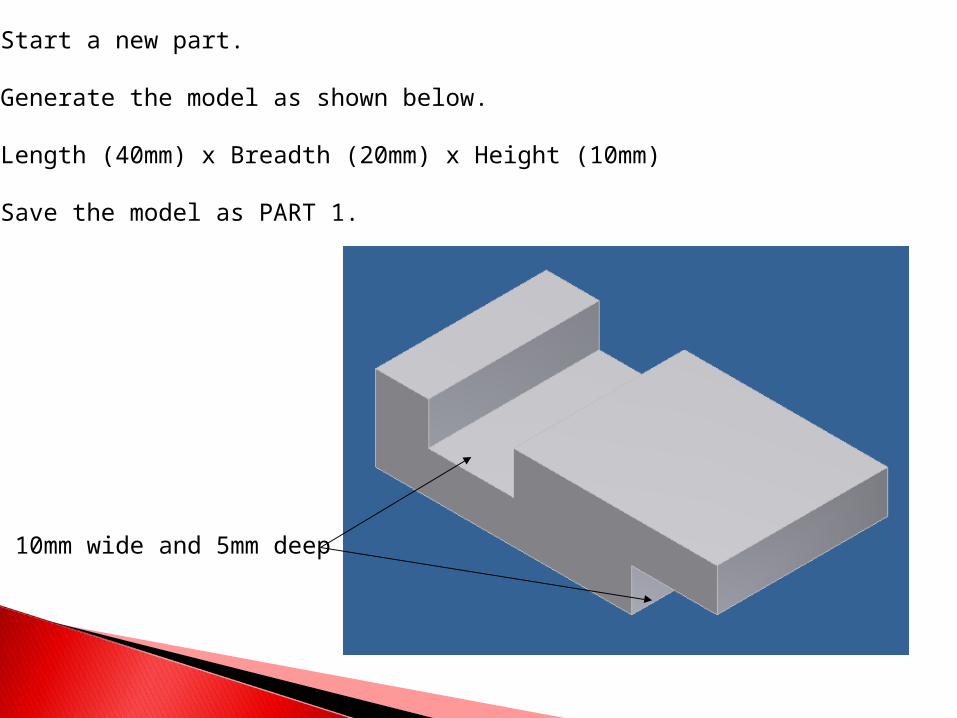
Start a new part.
Generate the model as shown below.
Length (40mm) x Breadth (20mm) x Height (10mm)
Save the model as PART 1.
10mm wide and 5mm deep
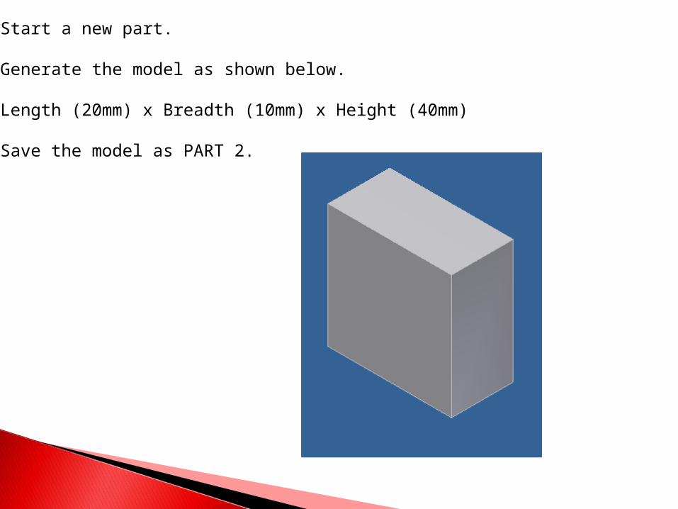
Start a new part.
Generate the model as shown below.
Length (20mm) x Breadth (10mm) x Height (40mm)
Save the model as PART 2.
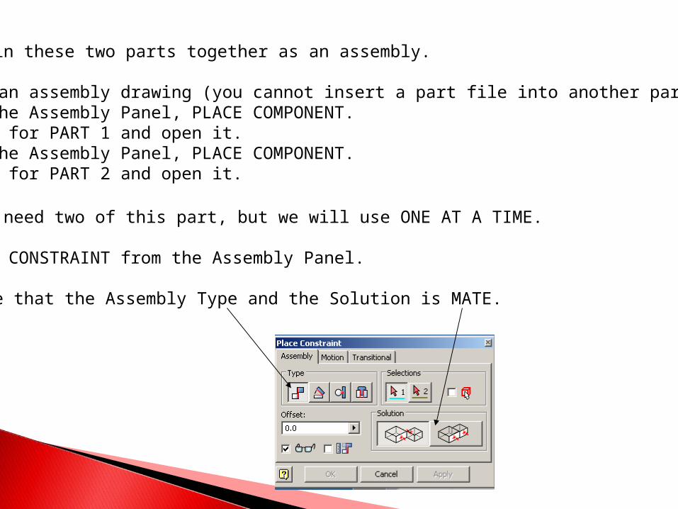
Let’s join these two parts together as an assembly.
1. Start an assembly drawing (you cannot insert a part file into another part file).2. From the Assembly Panel, PLACE COMPONENT.3. Browse for PART 1 and open it.4. From the Assembly Panel, PLACE COMPONENT.5. Browse for PART 2 and open it.
You will need two of this part, but we will use ONE AT A TIME.
6. Select CONSTRAINT from the Assembly Panel.
Make sure that the Assembly Type and the Solution is MATE.
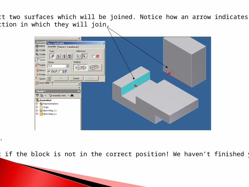
7. Select two surfaces which will be joined. Notice how an arrow indicates thedirection in which they will join.
8. Click OK.
Don’t panic if the block is not in the correct position! We haven’t finished yet!
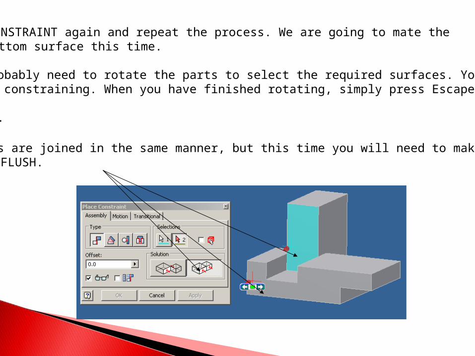
9. Select CONSTRAINT again and repeat the process. We are going to mate the bottom surface this time.
You will probably need to rotate the parts to select the required surfaces. You can dothis whilst constraining. When you have finished rotating, simply press Escape.
10.Click OK.
11.The sides are joined in the same manner, but this time you will need to make the Solution FLUSH.
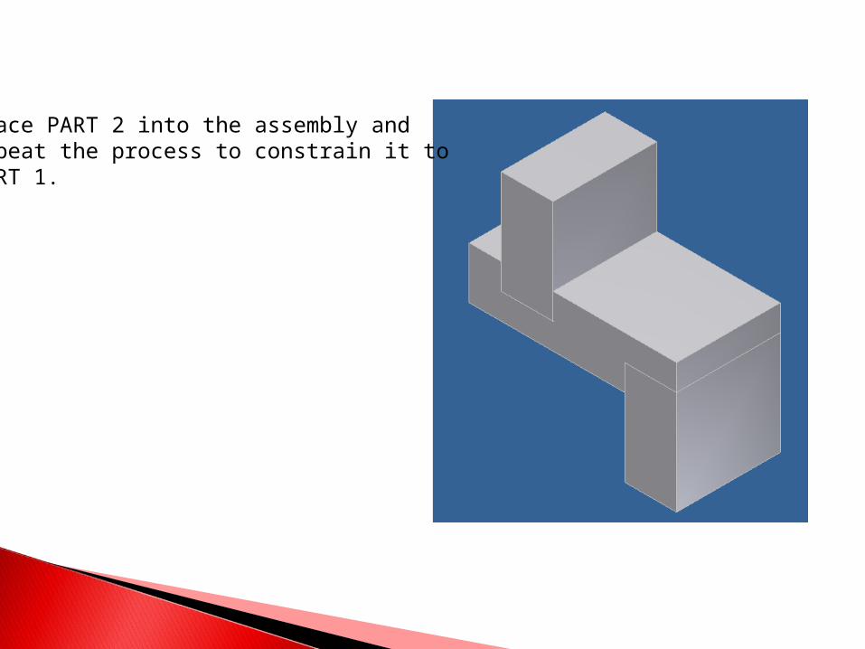
Place PART 2 into the assembly andrepeat the process to constrain it to PART 1.
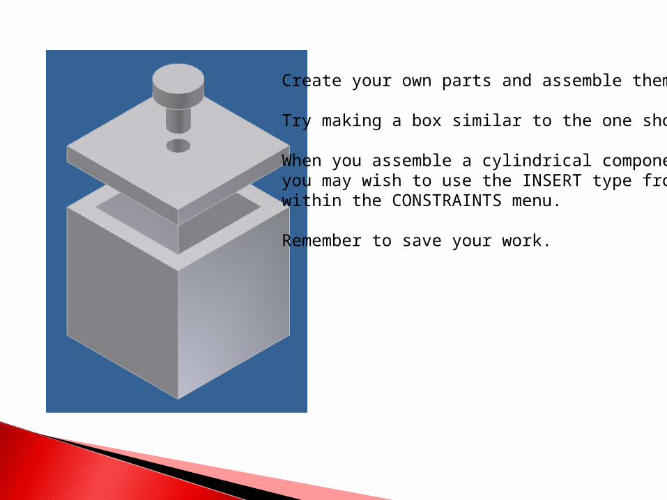
Create your own parts and assemble them.
Try making a box similar to the one shown.
When you assemble a cylindrical component,you may wish to use the INSERT type fromwithin the CONSTRAINTS menu.
Remember to save your work.