Embed Size (px)
Citation preview
ThunderboltEX II/DUAL
15060-35500200
User Guide
2
E9391 Revised Edition V3 June 2014
Copyright © 2014 ASUSTeK COMPUTER INC. All Rights Reserved.
No part of this manual, including the products and software described in it, may be reproduced, transmitted, transcribed, stored in a retrieval system, or translated into any language in any form or by any means, except documentation kept by the purchaser for backup purposes, without the express written permission of ASUSTeK COMPUTER INC. (“ASUS”).ASUS provides this manual “as is” without warranty of any kind, either express or implied, including but not limited to the implied warranties or conditions of merchantability or fitness for a particular purpose. In no event shall ASUS, its directors, officers, employees, or agents be liable for any indirect, special, incidental, or consequential damages (including damages for loss of profits, loss of business, loss of use or data, interruption of business and the like), even if ASUS has been advised of the possibility of such damages arising from any defect or error in this manual or product. Specifications and information contained in this manual ae furnished for informational use only, and are subject to change at any time without notice, and should not be construed as a commitment by ASUS. ASUS assumes no responsibility or liability for any errors or inaccuracies that may appear in this manual, including the products and software described in it.Product warranty or service will not be extended if: (1) the product is repaired, modified or altered, unless such repair, modification of alteration is authorized in writing by ASUS; or (2) the serial number of the product is defaced or missing.Products and corporate names appearing in this manual may or may not be registered trademarks or copyrights of their respective companies, and are used only for identification or explanation and to the owners’ benefit, without intent to infringe.
3
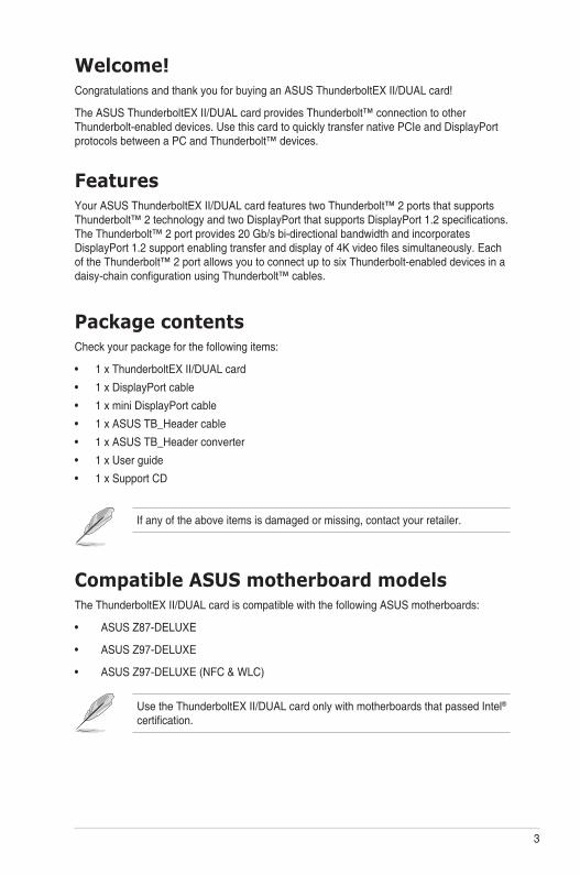
Package contentsCheck your package for the following items:
• 1 x ThunderboltEX II/DUAL card
• 1 x DisplayPort cable
• 1 x mini DisplayPort cable
• 1 x ASUS TB_Header cable
• 1 x ASUS TB_Header converter
• 1 x User guide
• 1 x Support CD
If any of the above items is damaged or missing, contact your retailer.
Compatible ASUS motherboard modelsThe ThunderboltEX II/DUAL card is compatible with the following ASUS motherboards:
• ASUS Z87-DELUXE
• ASUS Z97-DELUXE
• ASUS Z97-DELUXE (NFC & WLC)
Welcome!Congratulations and thank you for buying an ASUS ThunderboltEX II/DUAL card!
The ASUS ThunderboltEX II/DUAL card provides Thunderbolt™ connection to other Thunderbolt-enabled devices. Use this card to quickly transfer native PCIe and DisplayPort protocols between a PC and Thunderbolt™ devices.
FeaturesYour ASUS ThunderboltEX II/DUAL card features two Thunderbolt™ 2 ports that supports Thunderbolt™ 2 technology and two DisplayPort that supports DisplayPort 1.2 specifications. The Thunderbolt™ 2 port provides 20 Gb/s bi-directional bandwidth and incorporates DisplayPort 1.2 support enabling transfer and display of 4K video files simultaneously. Each of the Thunderbolt™ 2 port allows you to connect up to six Thunderbolt-enabled devices in a daisy-chain configuration using Thunderbolt™ cables.
Use the ThunderboltEX II/DUAL card only with motherboards that passed Intel® certification.
4
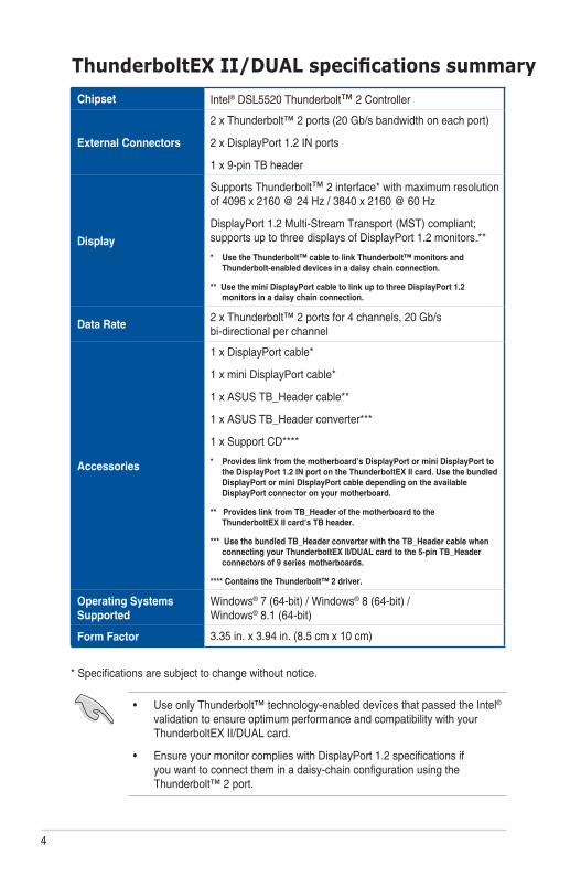
ThunderboltEX II/DUAL specifications summaryChipset Intel® DSL5520 Thunderbolt™ 2 Controller
External Connectors
2 x Thunderbolt™ 2 ports (20 Gb/s bandwidth on each port)
2 x DisplayPort 1.2 IN ports
1 x 9-pin TB header
Display
Supports Thunderbolt™ 2 interface* with maximum resolution of 4096 x 2160 @ 24 Hz / 3840 x 2160 @ 60 Hz
DisplayPort 1.2 Multi-Stream Transport (MST) compliant; supports up to three displays of DisplayPort 1.2 monitors.**
* Use the Thunderbolt™ cable to link Thunderbolt™ monitors and Thunderbolt-enabled devices in a daisy chain connection.
** Use the mini DisplayPort cable to link up to three DisplayPort 1.2 monitors in a daisy chain connection.
Data Rate2 x Thunderbolt™ 2 ports for 4 channels, 20 Gb/s bi-directional per channel
Accessories
1 x DisplayPort cable*
1 x mini DisplayPort cable*
1 x ASUS TB_Header cable**
1 x ASUS TB_Header converter***
1 x Support CD****
* Provides link from the motherboard’s DisplayPort or mini DisplayPort to the DisplayPort 1.2 IN port on the ThunderboltEX II card. Use the bundled DisplayPort or mini DIsplayPort cable depending on the available DisplayPort connector on your motherboard.
** Provides link from TB_Header of the motherboard to the ThunderboltEX II card’s TB header.
*** Use the bundled TB_Header converter with the TB_Header cable when connecting your ThunderboltEX II/DUAL card to the 5-pin TB_Header connectors of 9 series motherboards.
**** Contains the Thunderbolt™ 2 driver.
Operating Systems Supported
Windows® 7 (64-bit) / Windows® 8 (64-bit) / Windows® 8.1 (64-bit)
Form Factor 3.35 in. x 3.94 in. (8.5 cm x 10 cm)
* Specifications are subject to change without notice.
• Use only Thunderbolt™ technology-enabled devices that passed the Intel® validation to ensure optimum performance and compatibility with your ThunderboltEX II/DUAL card.
• Ensure your monitor complies with DisplayPort 1.2 specifications if you want to connect them in a daisy-chain configuration using the Thunderbolt™ 2 port.
5
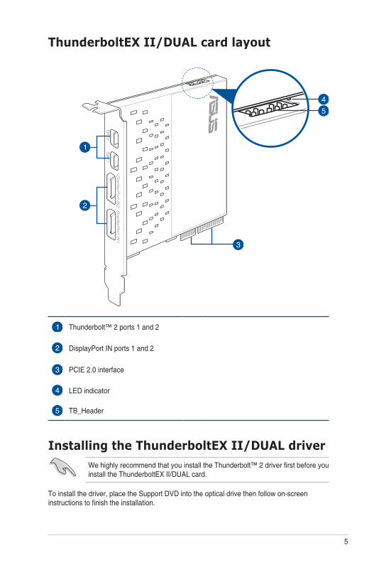
ThunderboltEX II/DUAL card layout
Thunderbolt™ 2 ports 1 and 2
DisplayPort IN ports 1 and 2
PCIE 2.0 interface
LED indicator
TB_Header
To install the driver, place the Support DVD into the optical drive then follow on-screen instructions to finish the installation.
Installing the ThunderboltEX II/DUAL driverWe highly recommend that you install the Thunderbolt™ 2 driver first before you install the ThunderboltEX II/DUAL card.
6
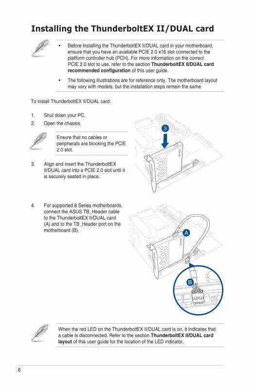
Installing the ThunderboltEX II/DUAL card
To install ThunderboltEX II/DUAL card:
• Before installing the ThunderboltEX II/DUAL card in your motherboard, ensure that you have an available PCIE 2.0 x16 slot connected to the platform controller hub (PCH). For more information on the correct PCIE 2.0 slot to use, refer to the section ThunderboltEX II/DUAL card recommended configuration of this user guide.
• The following illustrations are for reference only. The motherboard layout may vary with models, but the installation steps remain the same.
1. Shut down your PC.
2. Open the chassis.
Ensure that no cables or peripherals are blocking the PCIE 2.0 slot.
3. Align and insert the ThunderboltEX II/DUAL card into a PCIE 2.0 slot until it is securely seated in place.
When the red LED on the ThunderboltEX II/DUAL card is on, it indicates that a cable is disconnected. Refer to the section ThunderboltEX II/DUAL card layout of this user guide for the location of the LED indicator.
4. For supported 8 Series motherboards, connect the ASUS TB_Header cable to the ThunderboltEX II/DUAL card (A) and to the TB_Header port on the motherboard (B).
7
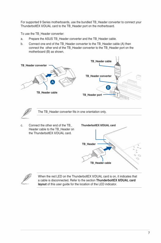
To use the TB_Header converter:
a. Prepare the ASUS TB_Header converter and the TB_Header cable.
b. Connect one end of the TB_Header converter to the TB_Header cable (A) then connect the other end of the TB_Header converter to the TB_Header port on the motherboard (B) as shown.
The TB_Header converter fits in one orientation only.
TB_Header converter
TB_Header cable
TB_Header converter
TB_Header cable
TB_Header
TB_Header port
For supported 9 Series motherboards, use the bundled TB_Header converter to connect your ThunderboltEX II/DUAL card to the TB_Header port on the motherboard.
c. Connect the other end of the TB_Header cable to the TB_Header on the ThunderboltEX II/DUAL card.
TB_Header cable
ThunderboltEX II/DUAL card
When the red LED on the ThunderboltEX II/DUAL card is on, it indicates that a cable is disconnected. Refer to the section ThunderboltEX II/DUAL card layout of this user guide for the location of the LED indicator.
8
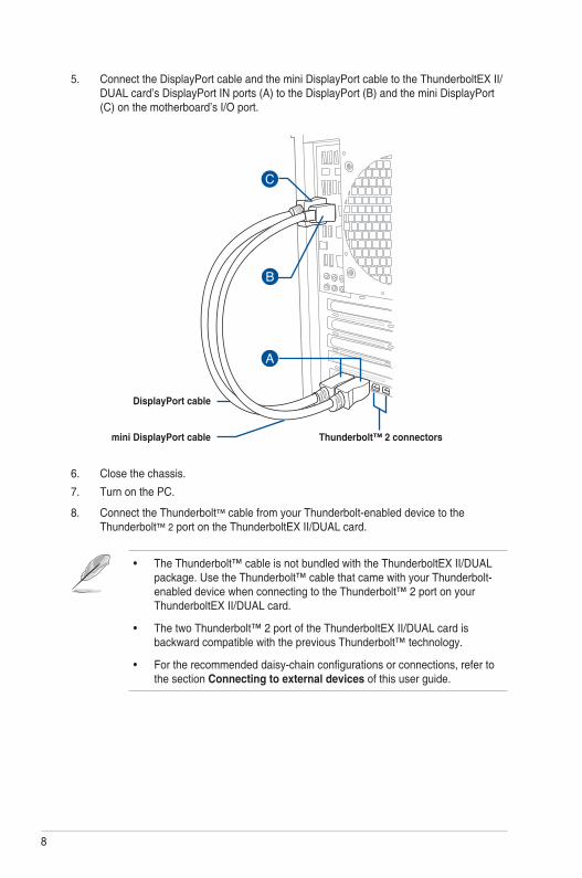
5. Connect the DisplayPort cable and the mini DisplayPort cable to the ThunderboltEX II/DUAL card’s DisplayPort IN ports (A) to the DisplayPort (B) and the mini DisplayPort (C) on the motherboard’s I/O port.
Thunderbolt™ 2 connectors
DisplayPort cable
mini DisplayPort cable
6. Close the chassis.
7. Turn on the PC.
8. Connect the Thunderbolt™ cable from your Thunderbolt-enabled device to the Thunderbolt™ 2 port on the ThunderboltEX II/DUAL card.
• The Thunderbolt™ cable is not bundled with the ThunderboltEX II/DUAL package. Use the Thunderbolt™ cable that came with your Thunderbolt-enabled device when connecting to the Thunderbolt™ 2 port on your ThunderboltEX II/DUAL card.
• The two Thunderbolt™ 2 port of the ThunderboltEX II/DUAL card is backward compatible with the previous Thunderbolt™ technology.
• For the recommended daisy-chain configurations or connections, refer to the section Connecting to external devices of this user guide.
9
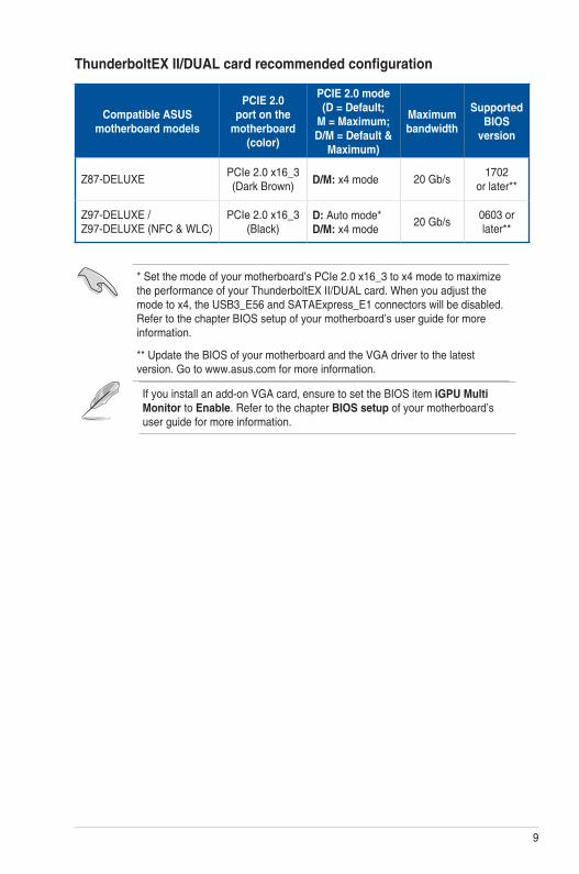
ThunderboltEX II/DUAL card recommended configuration
Compatible ASUS motherboard models
PCIE 2.0 port on the
motherboard (color)
PCIE 2.0 mode (D = Default;
M = Maximum; D/M = Default &
Maximum)
Maximum bandwidth
Supported BIOS
version
Z87-DELUXE PCIe 2.0 x16_3 (Dark Brown) D/M: x4 mode 20 Gb/s 1702
or later**
Z97-DELUXE / Z97-DELUXE (NFC & WLC)
PCIe 2.0 x16_3 (Black)
D: Auto mode* D/M: x4 mode
20 Gb/s 0603 or later**
* Set the mode of your motherboard’s PCIe 2.0 x16_3 to x4 mode to maximize the performance of your ThunderboltEX II/DUAL card. When you adjust the mode to x4, the USB3_E56 and SATAExpress_E1 connectors will be disabled. Refer to the chapter BIOS setup of your motherboard’s user guide for more information.
** Update the BIOS of your motherboard and the VGA driver to the latest version. Go to www.asus.com for more information.
If you install an add-on VGA card, ensure to set the BIOS item iGPU Multi Monitor to Enable. Refer to the chapter BIOS setup of your motherboard’s user guide for more information.
10
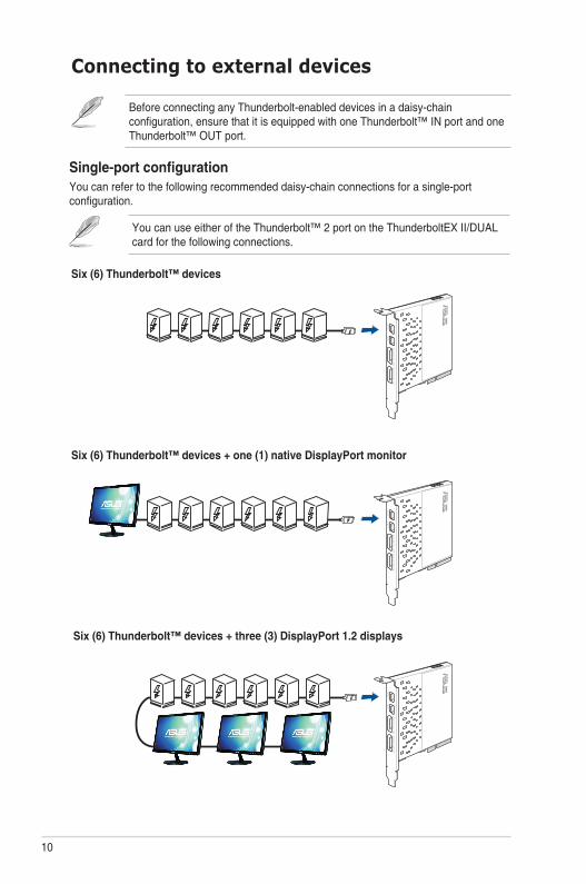
Single-port configurationYou can refer to the following recommended daisy-chain connections for a single-port configuration.
You can use either of the Thunderbolt™ 2 port on the ThunderboltEX II/DUAL card for the following connections.
Six (6) Thunderbolt™ devices + three (3) DisplayPort 1.2 displays
Six (6) Thunderbolt™ devices + one (1) native DisplayPort monitor
Six (6) Thunderbolt™ devices
Connecting to external devices
Before connecting any Thunderbolt-enabled devices in a daisy-chain configuration, ensure that it is equipped with one Thunderbolt™ IN port and one Thunderbolt™ OUT port.
11
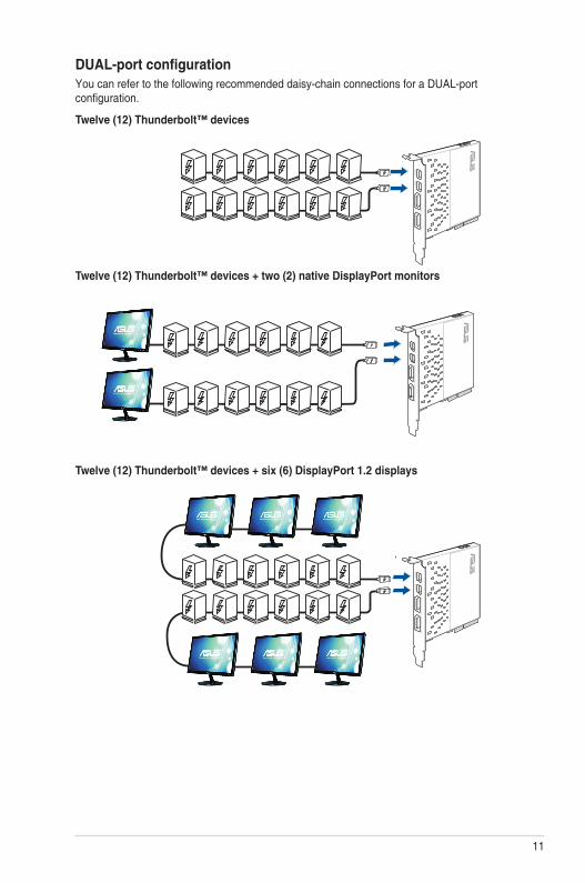
DUAL-port configurationYou can refer to the following recommended daisy-chain connections for a DUAL-port configuration.
Twelve (12) Thunderbolt™ devices + six (6) DisplayPort 1.2 displays
Twelve (12) Thunderbolt™ devices
Twelve (12) Thunderbolt™ devices + two (2) native DisplayPort monitors

12
NoticesFederal Communications Commission StatementThis device complies with Part 15 of the FCC Rules. Operation is subject to the following two conditions:
• This device may not cause harmful interference.
• This device must accept any interference received including interference that may cause undesired operation.
This equipment has been tested and found to comply with the limits for a Class B digital device, pursuant to Part 15 of the FCC Rules. These limits are designed to provide reasonable protection against harmful interference in a residential installation. This equipment generates, uses and can radiate radio frequency energy and, if not installed and used in accordance with manufacturer’s instructions, may cause harmful interference to radio communications. However, there is no guarantee that interference will not occur in a particular installation. If this equipment does cause harmful interference to radio or television reception, which can be determined by turning the equipment off and on, the user is encouraged to try to correct the interference by one or more of the following measures:
• Reorient or relocate the receiving antenna.
• Increase the separation between the equipment and receiver.
• Connect the equipment to an outlet on a circuit different from that to which the receiver is connected.
• Consult the dealer or an experienced radio/TV technician for help.
The use of shielded cables for connection of the monitor to the graphics card is required to assure compliance with FCC regulations. Changes or modifications to this unit not expressly approved by the party responsible for compliance could void the user’s authority to operate this equipment.
IC: Canadian Compliance StatementComplies with the Canadian ICES-003 Class B specifications. This device complies with RSS 210 of Industry Canada. This Class B device meets all the requirements of the Canadian interference-causing equipment regulations.
This device complies with Industry Canada license exempt RSS standard(s). Operation is subject to the following two conditions: (1) this device may not cause interference, and (2) this device must accept any interference, including interference that may cause undesired operation of the device.
Cut appareil numérique de la Classe B est conforme à la norme NMB-003 du Canada. Cet appareil numérique de la Classe B respecte toutes les exigences du Règlement sur le matériel brouilleur du Canada.
Cet appareil est conforme aux normes CNR exemptes de licence d’Industrie Canada. Le fonctionnement est soumis aux deux conditions suivantes :
(1) cet appareil ne doit pas provoquer d’interférences et
(2) cet appareil doit accepter toute interférence, y compris celles susceptibles de provoquer un fonctionnement non souhaité de l’appareil.
13
Canadian Department of Communications StatementThis digital apparatus does not exceed the Class B limits for radio noise emissions from digital apparatus set out in the Radio Interference Regulations of the Canadian Department of Communications.
This class B digital apparatus complies with Canadian ICES-003.
VCCI: Japan Compliance Statement
Class B ITE
This is a Class B product based on the standard of the VCCI Council. If this is used near a radio or television receiver in a domestic environment, it may cause radio interference. Install and use the equipment according to the instruction manual.
KC: Korea Warning Statement
REACHComplying with the REACH (Registration, Evaluation, Authorisation, and Restriction of Chemicals) regulatory framework, we published the chemical substances in our products at ASUS REACH website at http://csr.asus.com/english/REACH.htm.
DO NOT throw the motherboard in municipal waste. This product has been designed to enable proper reuse of parts and recycling. This symbol of the crossed out wheeled bin indicates that the product (electrical and electronic equipment) should not be placed in municipal waste. Check local regulations for disposal of electronic products.
DO NOT throw the mercury-containing button cell battery in municipal waste. This symbol of the crossed out wheeled bin indicates that the battery should not be placed in municipal waste.
14
ASUS Recycling/Takeback ServicesASUS recycling and takeback programs come from our commitment to the highest standards for protecting our environment. We believe in providing solutions for you to be able to responsibly recycle our products, batteries, other components as well as the packaging materials. Please go to http://csr.asus.com/english/Takeback.htm for detailed recycling information in different regions.
15
ASUS contact information
ASUSTeK COMPUTER INC.Address 15 Li-Te Road, Peitou, Taipei, Taiwan 11259Telephone +886-2-2894-3447Fax +886-2-2890-7798E-mail [email protected] site http://www.asus.com
Technical SupportTelephone +86-21-3842-9911Fax +86-21-5866-8722, ext. 9101#Online support http://support.asus.com/techserv/techserv.aspx
ASUS COMPUTER INTERNATIONAL (America)Address 800 Corporate Way, Fremont, CA 94539, USATelephone +1-510-739-3777Fax +1-510-608-4555Web site http://usa.asus.com
Technical SupportTelephone +1-812-284-0883Support fax +1-812-282-2787Online support http://support.asus.com/techserv/techserv.aspx
ASUS COMPUTER GmbH (Germany and Austria)Address Harkort Str. 21-23, 40880 Ratingen, GermanyFax +49-2102-959931Web site http://www.asus.com/deOnline contact http://eu-rma.asus.com/sales
Technical SupportTelephone +49-2102-5789555Support Fax +49-2102-959911Online support http://support.asus.com/techserv/techserv.aspx
EC
De
cla
rati
on
of
Co
nfo
rmit
y
We
, th
e u
nd
ers
ign
ed
, M
an
ufa
ctu
rer:
A
SU
ST
eK
CO
MP
UT
ER
IN
C.
Ad
dre
ss
, C
ity:
4F
, N
o. 1
50
, L
I-T
E R
d.,
PE
ITO
U,
TA
IPE
I 1
12
, T
AIW
AN
Co
un
try:
TA
IWA
N
A
uth
ori
ze
d r
ep
res
en
tati
ve
in
Eu
rop
e:
AS
US
CO
MP
UT
ER
Gm
bH
Ad
dre
ss
, C
ity:
HA
RK
OR
T S
TR
. 2
1-2
3, 4
08
80 R
AT
ING
EN
Co
un
try:
GE
RM
AN
Y
de
cla
re t
he
fo
llo
win
g a
pp
ara
tus:
Pro
du
ct
nam
e :
T
hu
nd
erb
olt
EX
II P
CI
EX
PR
ES
S C
ard
Mo
del n
am
e :
T
HU
ND
ER
BO
LT
EX
II/D
UA
L, T
HU
ND
ER
BO
LT
EX
II
co
nfo
rm w
ith
th
e e
ssen
tial re
qu
irem
en
ts o
f th
e f
ollo
win
g d
irecti
ves:
2004
/10
8/E
C-E
MC
Dir
ecti
ve
E
N 5
502
2:2
01
0+
AC
:20
11
E
N 6
100
0-3
-2:2
00
6+
A2
:20
09
E
N 5
501
3:2
00
1+
A1
:200
3+
A2:2
00
6
E
N 5
502
4:2
01
0
E
N 6
100
0-3
-3:2
00
8
E
N 5
502
0:2
00
7+
A1
1:2
01
1
1999
/5/E
C-R
&T
TE
Dir
ecti
ve
E
N 3
00
32
8 V
1.7
.1(2
00
6-1
0)
E
N 3
00
44
0-1
V1
.6.1
(20
10
-08
) E
N 3
00
44
0-2
V1
.4.1
(20
10
-08
) E
N 3
01
51
1 V
9.0
.2(2
00
3-0
3)
E
N 3
01
90
8-1
V5
.2.1
(20
11
-05
) E
N 3
01
90
8-2
V5
.2.1
(20
11
-07
) E
N 3
01
89
3 V
1.6
.1(2
01
1-1
1)
E
N 3
02
54
4-2
V1
.1.1
(20
09
-01
) E
N 3
02
62
3 V
1.1
.1(2
00
9-0
1)
E
N 5
036
0:2
00
1
E
N 6
247
9:2
01
0
E
N 5
038
5:2
00
2
E
N 6
231
1:2
00
8
E
N 3
01
48
9-1
V1
.9.2
(20
11
-09
) E
N 3
01
48
9-3
V1
.4.1
(20
02
-08
) E
N 3
01
48
9-4
V1
.4.1
(20
09
-05
) E
N 3
01
48
9-7
V1
.3.1
(20
05
-11
) E
N 3
01
48
9-9
V1
.4.1
(20
07
-11
) E
N 3
01
48
9-1
7 V
2.2
.1(2
01
2-0
9)
E
N 3
01
48
9-2
4 V
1.5
.1(2
01
0-0
9)
E
N 3
02
32
6-2
V1
.2.2
(20
07
-06
) E
N 3
02
32
6-3
V1
.3.1
(20
07
-09
) E
N 3
01
35
7-2
V1
.4.1
(20
08
-11
) E
N 3
02
29
1-1
V1
.1.1
(20
05
-07
) E
N 3
02
29
1-2
V1
.1.1
(20
05
-07
)
2006
/95/E
C-L
VD
Dir
ecti
ve
EN
60
95
0-1
/ A
12:2
011
E
N 6
006
5:2
00
2 / A
12
:20
11
2009
/12
5/E
C-E
rP D
irecti
ve
R
eg
ula
tio
n (
EC
) N
o. 1
275
/200
8
R
eg
ula
tio
n (
EC
) N
o. 6
42/2
009
R
eg
ula
tio
n (
EC
) N
o. 2
78/2
009
R
eg
ula
tio
n (
EC
) N
o. 6
17/2
013
2011/6
5/E
U-R
oH
S D
ire
cti
ve
V
er.
130816
CE
ma
rkin
g
De
cla
rati
on
Da
te:
13/1
2/2
01
3
Ye
ar
to b
eg
in a
ffix
ing
CE
ma
rkin
g:
201
3
Po
sitio
n : C
EO
Na
me
:
Je
rry S
he
n
Sig
na
ture
: __
__
___
__
_
(EC
co
nfo
rmity m
ark
ing)
D
EC
LA
RA
TIO
N O
F C
ON
FO
RM
IT
Y
Per F
CC P
art 2
Sec
tion
2. 1
077(
a)
R
esp
on
sib
le P
arty
N
am
e:
Asu
s C
om
pu
ter In
tern
atio
na
l
A
dd
ress:
80
0 C
orp
ora
te W
ay
, F
rem
on
t, C
A 9
45
39
.
Ph
on
e/F
ax
N
o:
(5
10
)7
39
-3
77
7/(5
10
)6
08
-4
55
5
here
by d
eclar
es th
at th
e pro
duct
P
rod
uc
t N
am
e :
Th
un
derb
olt
EX
II P
CI E
XP
RE
SS
Card
M
od
el
Nu
mb
er
: T
HU
ND
ER
BO
LT
EX
II/D
UA
L, T
HU
ND
ER
BO
LT
EX
II
Conf
orm
s to
the f
ollo
wing
spec
ifica
tions
:
FC
C Pa
rt 15
, Sub
part
B, U
nint
entio
nal R
adiat
ors
Su
pp
lem
en
ta
ry
In
fo
rm
atio
n:
This
devic
e com
plies
with
part
15 of
the F
CC R
ules.
Opera
tion i
s sub
ject t
o the
fo
llowi
ng tw
o co
nditi
ons:
(1) T
his d
evice
may
not
caus
e ha
rmfu
l inte
rferen
ce,
and (
2) th
is de
vice m
ust a
ccep
t any
inter
feren
ce re
ceive
d, inc
luding
inter
feren
ce
that m
ay ca
use u
ndes
ired o
perat
ion.
Repr
esen
tativ
e Per
son’
s Nam
e :
S
tev
e C
ha
ng
/ P
resid
en
t
Sign
ature
:
Date
:
D
ec. 1
3, 2
01
3
Ver.
120601