Embed Size (px)
Citation preview
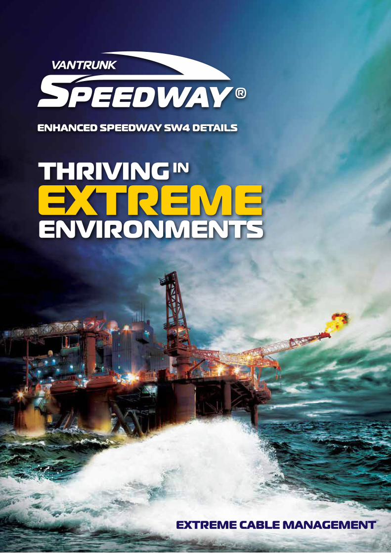
EnhancEd SpEEdway Sw4 dEtailS
thRiVinG in
EXtREME EnViROnMEntS
EXtREME caBlE ManaGEMEnt
32
Vantrunk Speedway Supplement
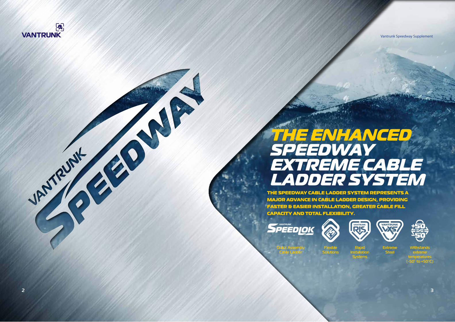
thE EnhancEd SpEEdway EXtREME caBlE laddER SyStEM
thE SpEEdway caBlE laddER SyStEM REpRESEntS a MaJOR adVancE in caBlE laddER dESiGn, pROVidinG FaStER & EaSiER inStallatiOn, GREatER caBlE Fill capacity and tOtal FlEXiBility.
Flexible Solutions
Rapid Installation
Systems
Extreme Steel
Withstands extreme
temperatures (-50° to +50°C)
Quick Assembly Cable Ladder

54
hOw tO ORdERCODE SYSTEM EXPLAINEDThe information given on these pages should be used as a guide when ordering Speedway
Cable Ladder, Fittings and Accessories. For more detailed information and examples refer to
the relevant page within the catalogue.
Finish and Materials ( )
MARINE GRADE STAINLESS
STEEL
HOT DIPPED GALVANIZED
VANTRUNK SILICON RICH STRUCTURAL
STEEL
HOT DIPPED GALVANIZED STRUCTURAL
STEEL
PRE GALVANIZED VANTRUNK
STRUCTURAL STEEL
HOT DIPPED GALVANIZED VANTRUNK MILD STEEL
DEEP GALVANIZED VANTRUNK
SILICON RICH STRUCTURAL
STEEL
GKGMHOT DIPPED GALVANIZED VANTRUNK
EXTREME STEEL
GY QQHOT DIPPED GALVANIZED VANTRUNK
ARCTIC STEEL
GDMARINE GRADE
STAINLESS STEEL
HOT DIPPED GALVANIZED
VANTRUNK SILICON RICH STRUCTURAL
STEEL
HOT DIPPED GALVANIZED STRUCTURAL
STEEL
PRE GALVANIZED VANTRUNK
STRUCTURAL STEEL
HOT DIPPED GALVANIZED VANTRUNK MILD STEEL
DEEP GALVANIZED VANTRUNK
SILICON RICH STRUCTURAL
STEEL
GKGMHOT DIPPED GALVANIZED VANTRUNK
EXTREME STEEL
GY QQHOT DIPPED GALVANIZED VANTRUNK
ARCTIC STEEL
GD
System Type Ladder Type Width Finish & Material
Speedway Straight Ladder
System Type Coupler Type Finish & Material
Speedway Couplers
eg. SW4 SL3 300 GY
eg. SW4 CS GA
Speedway Straight Ladder Covers
System Type Cover Type Width Finish & MaterialLadder Type
eg. SW4 CC SL3 300 GX
UpdAtEd pRodUCtS
At Vantrunk our commitment to continual improvement has lead us to further enhance our Speedway SW4 Cable Ladder. This supplement provides a handy guide for the newly updated products and the associated information changes.
This supplement should be used to reference these products until the launch of the new Vantrunk Product Guide in 2014.
Product Guide Page
Supplement Page Product
356 Speedway SW4 Cable Ladder
657 sw4 Straight Coupler
758 External Flange clamp
7610 Adaptable Fixing Bracket
7811 Speedway Hold Down Bracket
7912 Angle Securing Bracket
8213 Structural Connector Bracket
intRO
thRiVinG in
EXtREME EnViROnMEntS
pREORdER yOUR nEw catalOGUE tOday E-Mail : [email protected]
W
W1
H
L
300
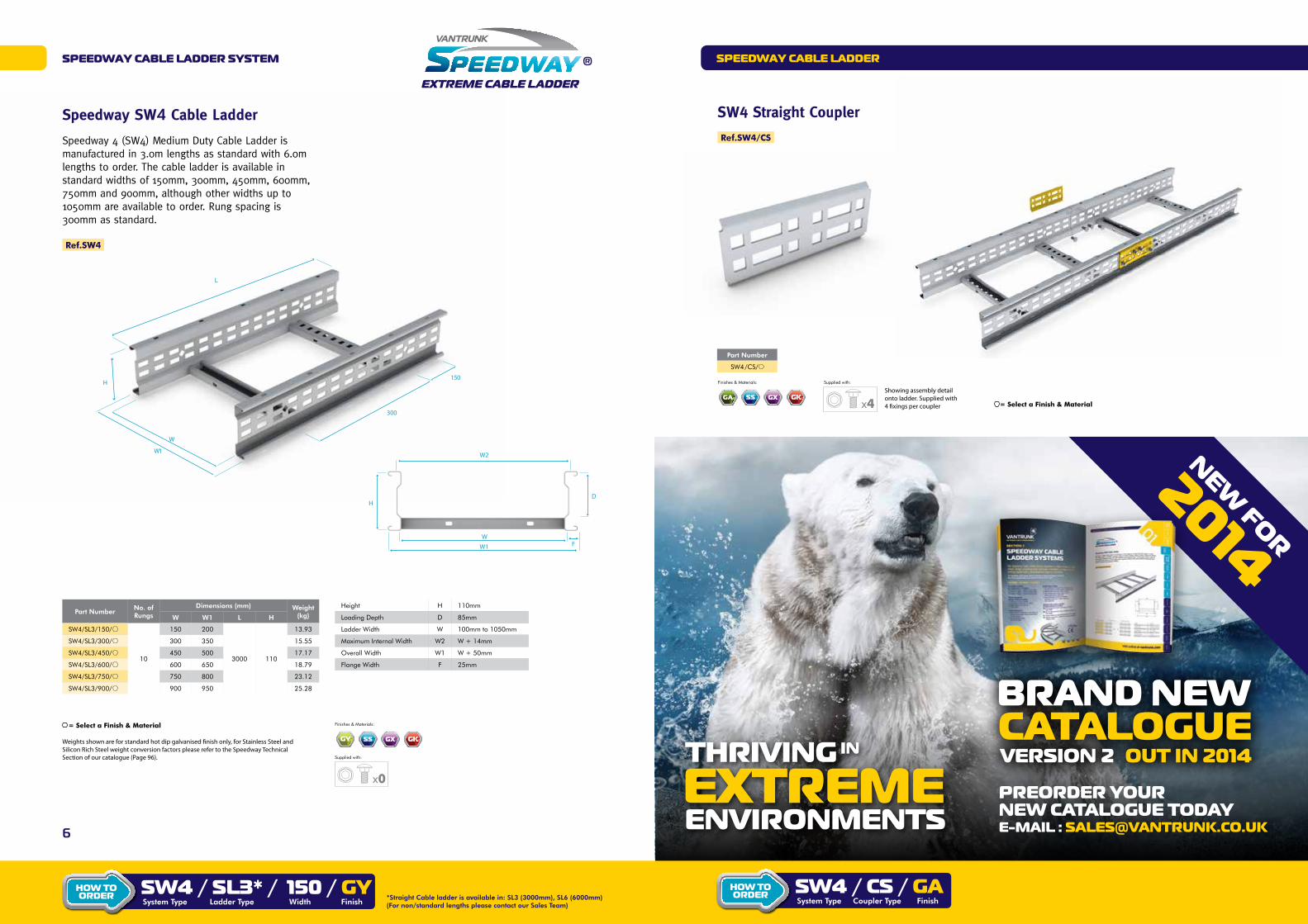
Speedway SW4 Cable Ladder
Speedway 4 (SW4) Medium Duty Cable Ladder is manufactured in 3.0m lengths as standard with 6.0m lengths to order. The cable ladder is available in standard widths of 150mm, 300mm, 450mm, 600mm, 750mm and 900mm, although other widths up to 1050mm are available to order. Rung spacing is 300mm as standard.
Ref.SW4
Part Number No. of Rungs
Dimensions (mm) Weight(kg)W W1 L H
SW4/SL3/150/
10
150 200
3000 110
13.93
SW4/SL3/300/ 300 350 15.55
SW4/SL3/450/ 450 500 17.17
SW4/SL3/600/ 600 650 18.79
SW4/SL3/750/ 750 800 23.12
SW4/SL3/900/ 900 950 25.28
Weights shown are for standard hot dip galvanised finish only, for Stainless Steel and Silicon Rich Steel weight conversion factors please refer to the Speedway Technical Section of our catalogue (Page 96).
= Select a Finish & Material
x0
Supplied with:
Finishes & Materials:
STAINLESSSTEEL
PRE-GALVANISED ELECTRO ZINC HOT DIPPED GALVANIZED SILICON
RICH STRUCTURAL STEEL
HOT DIPPED GALVANIZED STRUCTURAL
STEEL
HOT DIPPED GALVANIZED STRUCTURAL
STEEL
PRE GALVANIZED STRUCTURAL
STEEL
GALVANISED AFTER CORTEN STEELMULTICOLOUREDPOWDER COATED
GK GM GY QQZASTAINLESS
STEELPRE-GALVANISED ELECTRO ZINC HOT DIPPED
GALVANIZED SILICON RICH STRUCTURAL
STEEL
HOT DIPPED GALVANIZED STRUCTURAL
STEEL
HOT DIPPED GALVANIZED STRUCTURAL
STEEL
PRE GALVANIZED STRUCTURAL
STEEL
GALVANISED AFTER CORTEN STEELMULTICOLOUREDPOWDER COATED
GK GM GY QQZASTAINLESS
STEELPRE-GALVANISED ELECTRO ZINC HOT DIPPED
GALVANIZED SILICON RICH STRUCTURAL
STEEL
HOT DIPPED GALVANIZED STRUCTURAL
STEEL
HOT DIPPED GALVANIZED STRUCTURAL
STEEL
PRE GALVANIZED STRUCTURAL
STEEL
GALVANISED AFTER CORTEN STEELMULTICOLOUREDPOWDER COATED
GK GM GY QQZASTAINLESS
STEELPRE-GALVANISED ELECTRO ZINC HOT DIPPED
GALVANIZED SILICON RICH STRUCTURAL
STEEL
HOT DIPPED GALVANIZED STRUCTURAL
STEEL
HOT DIPPED GALVANIZED STRUCTURAL
STEEL
PRE GALVANIZED STRUCTURAL
STEEL
GALVANISED AFTER CORTEN STEELMULTICOLOUREDPOWDER COATED
GK GM GY QQZA
Height H 110mm
Loading Depth D 85mm
Ladder Width W 100mm to 1050mm
Maximum Internal Width W2 W + 14mm
Overall Width W1 W + 50mm
Flange Width F 25mm
SpEEdway caBlE laddER SyStEM SpEEdway caBlE laddER
Sw4 / Sl3* / 150 / GySystem Type Ladder Type Width Finish
*Straight Cable ladder is available in: SL3 (3000mm), SL6 (6000mm) (For non/standard lengths please contact our Sales Team)
hOw tO ORdER
SW4 Straight Coupler
Ref.SW4/CS
Part Number
SW4/CS/
x4
Supplied with: Finishes & Materials:
STAINLESSSTEEL
PRE-GALVANISED ELECTRO ZINC HOT DIPPED GALVANIZED SILICON
RICH STRUCTURAL STEEL
HOT DIPPED GALVANIZED STRUCTURAL
STEEL
HOT DIPPED GALVANIZED STRUCTURAL
STEEL
PRE GALVANIZED STRUCTURAL
STEEL
GALVANISED AFTER CORTEN STEELMULTICOLOUREDPOWDER COATED
GK GM GY QQZASTAINLESS
STEELPRE-GALVANISED ELECTRO ZINC HOT DIPPED
GALVANIZED SILICON RICH STRUCTURAL
STEEL
HOT DIPPED GALVANIZED STRUCTURAL
STEEL
HOT DIPPED GALVANIZED STRUCTURAL
STEEL
PRE GALVANIZED STRUCTURAL
STEEL
GALVANISED AFTER CORTEN STEELMULTICOLOUREDPOWDER COATED
GK GM GY QQZASTAINLESS
STEELPRE-GALVANISED ELECTRO ZINC HOT DIPPED
GALVANIZED SILICON RICH STRUCTURAL
STEEL
HOT DIPPED GALVANIZED STRUCTURAL
STEEL
HOT DIPPED GALVANIZED STRUCTURAL
STEEL
PRE GALVANIZED STRUCTURAL
STEEL
GALVANISED AFTER CORTEN STEELMULTICOLOUREDPOWDER COATED
GK GM GY QQZAShowing assembly detail onto ladder. Supplied with 4 fixings per coupler = Select a Finish & Material
STAINLESSSTEEL
PRE-GALVANISED ELECTRO ZINC HOT DIPPED GALVANIZED SILICON
RICH STRUCTURAL STEEL
HOT DIPPED GALVANIZED STRUCTURAL
STEEL
HOT DIPPED GALVANIZED STRUCTURAL
STEEL
PRE GALVANIZED STRUCTURAL
STEEL
GALVANISED AFTER CORTEN STEELMULTICOLOUREDPOWDER COATED
GK GM GY QQZA
Sw4 / cS / GaSystem Type Coupler Type Finish
hOw tO ORdER
W2
HD
W1
WF
150
8 9
accESSORiES
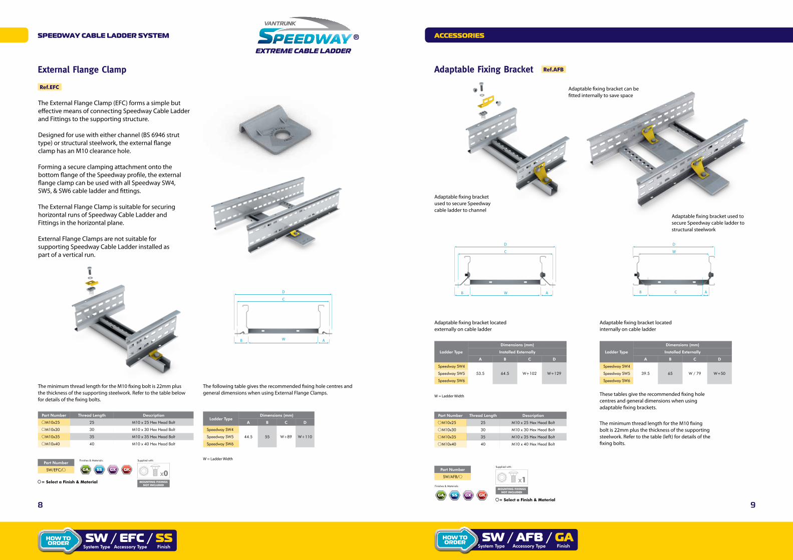
External Flange Clamp
Ref.EFC
The External Flange Clamp (EFC) forms a simple but effective means of connecting Speedway Cable Ladder and Fittings to the supporting structure.
Designed for use with either channel (BS 6946 strut type) or structural steelwork, the external flange clamp has an M10 clearance hole.
Forming a secure clamping attachment onto the bottom flange of the Speedway profile, the external flange clamp can be used with all Speedway SW4, SW5, & SW6 cable ladder and fittings.
The External Flange Clamp is suitable for securing horizontal runs of Speedway Cable Ladder and Fittings in the horizontal plane.
External Flange Clamps are not suitable for supporting Speedway Cable Ladder installed as part of a vertical run.
WB A
C
D
Ladder TypeDimensions (mm)
A B C D
Speedway SW4
44.5 55 W+89 W+110Speedway SW5
Speedway SW6
W = Ladder Width
The following table gives the recommended fixing hole centres and general dimensions when using External Flange Clamps.
Part Number Thread Length Description
M10x25 25 M10 x 25 Hex Head Bolt
M10x30 30 M10 x 30 Hex Head Bolt
M10x35 35 M10 x 35 Hex Head Bolt
M10x40 40 M10 x 40 Hex Head Bolt
The minimum thread length for the M10 fixing bolt is 22mm plus the thickness of the supporting steelwork. Refer to the table below for details of the fixing bolts.
Part Number
SW/EFC/
= Select a Finish & Material
x0
Supplied with: Finishes & Materials:
STAINLESSSTEEL
PRE-GALVANISED ELECTRO ZINC HOT DIPPED GALVANIZED SILICON
RICH STRUCTURAL STEEL
HOT DIPPED GALVANIZED STRUCTURAL
STEEL
HOT DIPPED GALVANIZED STRUCTURAL
STEEL
PRE GALVANIZED STRUCTURAL
STEEL
GALVANISED AFTER CORTEN STEELMULTICOLOUREDPOWDER COATED
GK GM GY QQZASTAINLESS
STEELPRE-GALVANISED ELECTRO ZINC HOT DIPPED
GALVANIZED SILICON RICH STRUCTURAL
STEEL
HOT DIPPED GALVANIZED STRUCTURAL
STEEL
HOT DIPPED GALVANIZED STRUCTURAL
STEEL
PRE GALVANIZED STRUCTURAL
STEEL
GALVANISED AFTER CORTEN STEELMULTICOLOUREDPOWDER COATED
GK GM GY QQZASTAINLESS
STEELPRE-GALVANISED ELECTRO ZINC HOT DIPPED
GALVANIZED SILICON RICH STRUCTURAL
STEEL
HOT DIPPED GALVANIZED STRUCTURAL
STEEL
HOT DIPPED GALVANIZED STRUCTURAL
STEEL
PRE GALVANIZED STRUCTURAL
STEEL
GALVANISED AFTER CORTEN STEELMULTICOLOUREDPOWDER COATED
GK GM GY QQZA
MOUNTING FIXINGS NOT INCLUDED
STAINLESSSTEEL
PRE-GALVANISED ELECTRO ZINC HOT DIPPED GALVANIZED SILICON
RICH STRUCTURAL STEEL
HOT DIPPED GALVANIZED STRUCTURAL
STEEL
HOT DIPPED GALVANIZED STRUCTURAL
STEEL
PRE GALVANIZED STRUCTURAL
STEEL
GALVANISED AFTER CORTEN STEELMULTICOLOUREDPOWDER COATED
GK GM GY QQZA
Sw / EFc / SSAccessory Type Finish
hOw tO ORdER
System Type
Adaptable fixing bracket used to secure Speedway cable ladder to channel
Adaptable fixing bracket can be fitted internally to save space
Adaptable fixing bracket used to secure Speedway cable ladder to structural steelwork
WB A
C
D
CB A
W
D
Adaptable fixing bracket locatedexternally on cable ladder
Adaptable fixing bracket locatedinternally on cable ladder
Ladder Type
Dimensions (mm)
Installed Externally
A B C D
Speedway SW4
53.5 64.5 W+102 W+129Speedway SW5
Speedway SW6
Part Number Thread Length Description
M10x25 25 M10 x 25 Hex Head Bolt
M10x30 30 M10 x 30 Hex Head Bolt
M10x35 35 M10 x 35 Hex Head Bolt
M10x40 40 M10 x 40 Hex Head Bolt
Ladder Type
Dimensions (mm)
Installed Externally
A B C D
Speedway SW4
39.5 65 W / 79 W+50Speedway SW5
Speedway SW6
These tables give the recommended fixing hole centres and general dimensions when using adaptable fixing brackets.
W = Ladder Width
The minimum thread length for the M10 fixing bolt is 22mm plus the thickness of the supporting steelwork. Refer to the table (left) for details of the fixing bolts.
SpEEdway caBlE laddER SyStEM
Adaptable Fixing Bracket Ref.AFB
Sw / aFB / GaFinish
hOw tO ORdER
Accessory TypeSystem Type
= Select a Finish & Material
x1
Supplied with:
MOUNTING FIXINGS NOT INCLUDED
Part Number
SW/AFB/
Finishes & Materials:
STAINLESSSTEEL
PRE-GALVANISED ELECTRO ZINC HOT DIPPED GALVANIZED SILICON
RICH STRUCTURAL STEEL
HOT DIPPED GALVANIZED STRUCTURAL
STEEL
HOT DIPPED GALVANIZED STRUCTURAL
STEEL
PRE GALVANIZED STRUCTURAL
STEEL
GALVANISED AFTER CORTEN STEELMULTICOLOUREDPOWDER COATED
GK GM GY QQZASTAINLESS
STEELPRE-GALVANISED ELECTRO ZINC HOT DIPPED
GALVANIZED SILICON RICH STRUCTURAL
STEEL
HOT DIPPED GALVANIZED STRUCTURAL
STEEL
HOT DIPPED GALVANIZED STRUCTURAL
STEEL
PRE GALVANIZED STRUCTURAL
STEEL
GALVANISED AFTER CORTEN STEELMULTICOLOUREDPOWDER COATED
GK GM GY QQZASTAINLESS
STEELPRE-GALVANISED ELECTRO ZINC HOT DIPPED
GALVANIZED SILICON RICH STRUCTURAL
STEEL
HOT DIPPED GALVANIZED STRUCTURAL
STEEL
HOT DIPPED GALVANIZED STRUCTURAL
STEEL
PRE GALVANIZED STRUCTURAL
STEEL
GALVANISED AFTER CORTEN STEELMULTICOLOUREDPOWDER COATED
GK GM GY QQZASTAINLESS
STEELPRE-GALVANISED ELECTRO ZINC HOT DIPPED
GALVANIZED SILICON RICH STRUCTURAL
STEEL
HOT DIPPED GALVANIZED STRUCTURAL
STEEL
HOT DIPPED GALVANIZED STRUCTURAL
STEEL
PRE GALVANIZED STRUCTURAL
STEEL
GALVANISED AFTER CORTEN STEELMULTICOLOUREDPOWDER COATED
GK GM GY QQZA

10 11
accESSORiES
Speedway Hold Down Bracket
The Speedway Hold Down Bracket (HDB) is a simple but effective means of securing Speedway Cable Ladder and Fittings to the supporting structure. The Hold Down Bracket has a single M10 clearance slot which allows for easy adjustment to suit predrilled fixing holes in the supporting structure. The Hold Down Bracket is equally suited for installation on channel (BS 6946 strut type) or steelwork.
Fixings not supplied.
Hold Down Brackets are not suitable for supporting Speedway Cable Ladder installed as part of a vertical run.
Ref.HDB
25mm x 11.5mm slot
WB A
C
D
Speedway hold down bracket fitted onto Speedway cable ladder
Ladder TypeDimensions (mm)
A B C D
Speedway SW4
45 65 W+90 W+130Speedway SW5
Speedway SW6
Part Number Thread Length Description
M10x25 25 M10 x 25 Hex Head Bolt
M10x30 30 M10 x 30 Hex Head Bolt
M10x35 35 M10 x 35 Hex Head Bolt
M10x40 40 M10 x 40 Hex Head Bolt
The minimum thread length for the M10 fixing bolt is 22mm plus the thickness of the supporting steelwork. Refer to the table above for details of the fixing bolts.
Part Number
SW /HDB/
x0
Supplied with: Finishes & Materials:
STAINLESSSTEEL
PRE-GALVANISED ELECTRO ZINC HOT DIPPED GALVANIZED SILICON
RICH STRUCTURAL STEEL
HOT DIPPED GALVANIZED STRUCTURAL
STEEL
HOT DIPPED GALVANIZED STRUCTURAL
STEEL
PRE GALVANIZED STRUCTURAL
STEEL
GALVANISED AFTER CORTEN STEELMULTICOLOUREDPOWDER COATED
GK GM GY QQZASTAINLESS
STEELPRE-GALVANISED ELECTRO ZINC HOT DIPPED
GALVANIZED SILICON RICH STRUCTURAL
STEEL
HOT DIPPED GALVANIZED STRUCTURAL
STEEL
HOT DIPPED GALVANIZED STRUCTURAL
STEEL
PRE GALVANIZED STRUCTURAL
STEEL
GALVANISED AFTER CORTEN STEELMULTICOLOUREDPOWDER COATED
GK GM GY QQZASTAINLESS
STEELPRE-GALVANISED ELECTRO ZINC HOT DIPPED
GALVANIZED SILICON RICH STRUCTURAL
STEEL
HOT DIPPED GALVANIZED STRUCTURAL
STEEL
HOT DIPPED GALVANIZED STRUCTURAL
STEEL
PRE GALVANIZED STRUCTURAL
STEEL
GALVANISED AFTER CORTEN STEELMULTICOLOUREDPOWDER COATED
GK GM GY QQZA
= Select a Ladder Type= Select a Finish & Material
MOUNTING FIXINGS NOT INCLUDED
STAINLESSSTEEL
PRE-GALVANISED ELECTRO ZINC HOT DIPPED GALVANIZED SILICON
RICH STRUCTURAL STEEL
HOT DIPPED GALVANIZED STRUCTURAL
STEEL
HOT DIPPED GALVANIZED STRUCTURAL
STEEL
PRE GALVANIZED STRUCTURAL
STEEL
GALVANISED AFTER CORTEN STEELMULTICOLOUREDPOWDER COATED
GK GM GY QQZA
W = Ladder Width
Sw4 / hdB / SSSystem Type Finish
hOw tO ORdER
Accessory Type
SpEEdway caBlE laddER SyStEM
Angle Securing Bracket
The Speedway Angle Securing Bracket (ASB) is designed to connect Speedway SW4, SW5, & SW6 Cable Ladder to supporting structural angles. The 40mm x 11.5mm slots in both faces of the Angle Securing Bracket make installation quick & easy (M10 fixing recommended). The Angle Securing Bracket is supplied with one ladder fixing bracket as standard.
Ref.ASB
Supplied with one ladder fixing.
C
W
BA
Speedway angle securing bracket fitted onto Speedway cable ladder
Part Number
SW/ASB/
Part Number Thread Length Description
M10x25 25 M10 x 25 Hex Head Bolt
M10x30 30 M10 x 30 Hex Head Bolt
M10x35 35 M10 x 25 Hex Head Bolt
M10x40 40 M10 x 30 Hex Head Bolt
The minimum thread length for the M10 fixing bolt is 22mm plus the thickness of the supporting steelwork. Refer to the table above for details of the fixing bolts.
Ladder TypeDimensions (mm)
A B C
Speedway SW4
W+36 W+86 24Speedway SW5
Speedway SW6
W = Ladder Width
x1
Supplied with: Finishes & Materials:
STAINLESSSTEEL
PRE-GALVANISED ELECTRO ZINC HOT DIPPED GALVANIZED SILICON
RICH STRUCTURAL STEEL
HOT DIPPED GALVANIZED STRUCTURAL
STEEL
HOT DIPPED GALVANIZED STRUCTURAL
STEEL
PRE GALVANIZED STRUCTURAL
STEEL
GALVANISED AFTER CORTEN STEELMULTICOLOUREDPOWDER COATED
GK GM GY QQZASTAINLESS
STEELPRE-GALVANISED ELECTRO ZINC HOT DIPPED
GALVANIZED SILICON RICH STRUCTURAL
STEEL
HOT DIPPED GALVANIZED STRUCTURAL
STEEL
HOT DIPPED GALVANIZED STRUCTURAL
STEEL
PRE GALVANIZED STRUCTURAL
STEEL
GALVANISED AFTER CORTEN STEELMULTICOLOUREDPOWDER COATED
GK GM GY QQZASTAINLESS
STEELPRE-GALVANISED ELECTRO ZINC HOT DIPPED
GALVANIZED SILICON RICH STRUCTURAL
STEEL
HOT DIPPED GALVANIZED STRUCTURAL
STEEL
HOT DIPPED GALVANIZED STRUCTURAL
STEEL
PRE GALVANIZED STRUCTURAL
STEEL
GALVANISED AFTER CORTEN STEELMULTICOLOUREDPOWDER COATED
GK GM GY QQZA
= Select a Finish & Material MOUNTING FIXINGS NOT INCLUDED
STAINLESSSTEEL
PRE-GALVANISED ELECTRO ZINC HOT DIPPED GALVANIZED SILICON
RICH STRUCTURAL STEEL
HOT DIPPED GALVANIZED STRUCTURAL
STEEL
HOT DIPPED GALVANIZED STRUCTURAL
STEEL
PRE GALVANIZED STRUCTURAL
STEEL
GALVANISED AFTER CORTEN STEELMULTICOLOUREDPOWDER COATED
GK GM GY QQZA

12 13
tEchnical data
Structural Connector Bracket
As an alternative to using a vertical adjustable coupler, the Speedway Structural Connector Bracket (SCB) is specifically designed for connecting Speedway Cable Ladder runs to walls and floors.
The Structural Connector Bracket has two 11mm diameter (M10 clearance) fixing holes and is supplied complete with all necessary ladder fixing sets.
Supplied with ladder fixing sets only
Ref.ASB
Speedway structural connecting bracket securinghorizontal cable ladder to vertical channel support
Speedway structural connector bracketsecuring a horizontal cable ladder to a wall
WB A
C
D
C
11mmW = Ladder Width
Ladder TypeDimensions (mm)
A B C D E
Speedway SW4
47 67 W+94 W+134 30Speedway SW5
Speedway SW6
Part Number
SW /SCB/
x4
Supplied with: Finishes & Materials:
STAINLESSSTEEL
PRE-GALVANISED ELECTRO ZINC HOT DIPPED GALVANIZED SILICON
RICH STRUCTURAL STEEL
HOT DIPPED GALVANIZED STRUCTURAL
STEEL
HOT DIPPED GALVANIZED STRUCTURAL
STEEL
PRE GALVANIZED STRUCTURAL
STEEL
GALVANISED AFTER CORTEN STEELMULTICOLOUREDPOWDER COATED
GK GM GY QQZASTAINLESS
STEELPRE-GALVANISED ELECTRO ZINC HOT DIPPED
GALVANIZED SILICON RICH STRUCTURAL
STEEL
HOT DIPPED GALVANIZED STRUCTURAL
STEEL
HOT DIPPED GALVANIZED STRUCTURAL
STEEL
PRE GALVANIZED STRUCTURAL
STEEL
GALVANISED AFTER CORTEN STEELMULTICOLOUREDPOWDER COATED
GK GM GY QQZASTAINLESS
STEELPRE-GALVANISED ELECTRO ZINC HOT DIPPED
GALVANIZED SILICON RICH STRUCTURAL
STEEL
HOT DIPPED GALVANIZED STRUCTURAL
STEEL
HOT DIPPED GALVANIZED STRUCTURAL
STEEL
PRE GALVANIZED STRUCTURAL
STEEL
GALVANISED AFTER CORTEN STEELMULTICOLOUREDPOWDER COATED
GK GM GY QQZA
= Select a Ladder Type = Select a Finish & Material
MOUNTING FIXINGS NOT INCLUDED
STAINLESSSTEEL
PRE-GALVANISED ELECTRO ZINC HOT DIPPED GALVANIZED SILICON
RICH STRUCTURAL STEEL
HOT DIPPED GALVANIZED STRUCTURAL
STEEL
HOT DIPPED GALVANIZED STRUCTURAL
STEEL
PRE GALVANIZED STRUCTURAL
STEEL
GALVANISED AFTER CORTEN STEELMULTICOLOUREDPOWDER COATED
GK GM GY QQZA
Sw4 / ScB / GaSystem Type Finish
hOw tO ORdER
Accessory Type
SpEEdway caBlE laddER SyStEM
1. GEnERal inFORMatiOn
1.1 Slot patterns
Details of the slot patterns for the Speedway cable ladder system are given in the following diagrams. These slot patterns are common for each Speedway cable ladder type, irrespective of material gauge.
Speedway SW4 Fittings
The slot pattern for the Speedway SW4 fittings is repeated at each end of the fitting side wall and centrally on radial side walls (elbows, tees & crosses).
Speedway SW4 Straight Ladder
T = Side Wall Gauge (See section 1.2 for details).
1.2 cross Sectional area
SpeedwaySW4 Ladder
CSAmm2
SW4/SL3/150/# 13780
SW4/SL3/300/# 26740
SW4/SL3/450/# 39700
SW4/SL3/600/# 52660
SW4/SL3/750/# 65620
SW4/SL3/900/# 78580
Speedway cable ladder has the following cross/sectional area (CSA)
# Add Finish & Material
1.3 Sw4 Specification
The following is a typical specification for a cable ladder system which embodies the key features of the Speedway SW4 Cable Ladder system.
1 The cable ladder system shall be based on two longitudinal outward facing side members with returned edge flanges to improve safety during handling, installation and cable pulling activities.
The longitudinal side members shall form the main structural elements of the cable ladder system and shall be longitudinally ribbed for enhanced stiffness and rigidity.
2 The profile of the side members shall remain constant for the straight cable ladder and the cable ladder fittings.
3 The profile of the side members shall present a smooth surface to allow for easier cable pulling and to minimise the opportunities for damage to the cable insulation.
4 The longitudinal side members shall have a height of: • 110mmandaflangewidthof25mm
5 The longitudinal side member shall have a wall thickness of: • 1.5mm* • orrequiredsidewallthickness– see 1.2 for details.
SpEEdwaytEchnical data
14 15
Ladder Type Widthw mm
Span & Safe Working Load kg/m
2m 2.5m 3m 3.5m 4m 4.5m 5m 5.5m 6m
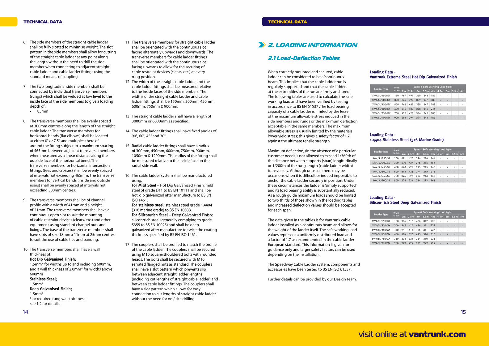
SW4/SL/150/GY 150 769 491 339 248 189 - - - -
SW4/SL/300/GY 300 769 490 339 247 188 - - - -
SW4/SL/450/GY 450 768 489 338 247 188 - - - -
SW4/SL/600/GY 600 542 489 338 246 246 - - - -
SW4/SL/750/GY 750 428 428 336 245 186 - - - -
SW4/SL/900/GY 900 294 294 294 244 185 - - - -
Ladder Type Widthw mm
Span & Safe Working Load kg/m
2m 2.5m 3m 3.5m 4m 4.5m 5m 5.5m 6m
SW4/SL/150/SS 150 671 428 296 216 164 - - - -
SW4/SL/300/SS 300 670 427 295 216 164 - - - -
SW4/SL/450/SS 450 670 427 295 215 163 - - - -
SW4/SL/600/SS 600 513 426 294 215 215 - - - -
SW4/SL/750/SS 750 326 326 294 214 162 - - - -
SW4/SL/900/SS 900 224 224 224 213 162 - - - -
Ladder Type Widthw mm
Span & Safe Working Load kg/m
2m 2.5m 3m 3.5m 4m 4.5m 5m 5.5m 6m
SW4/SL/150/GX 150 966 616 426 312 238 - - - -
SW4/SL/300/GX 300 965 616 426 311 237 - - - -
SW4/SL/450/GX 450 941 615 425 311 237 - - - -
SW4/SL/600/GX 600 526 526 425 310 310 - - - -
SW4/SL/750/GX 750 334 334 334 310 235 - - - -
SW4/SL/900/GX 900 229 229 229 229 229 - - - -
Loading Data - Vantrunk Extreme Steel Hot Dip Galvnaized Finish
Loading Data - 1.4404 Stainless Steel (316 Marine Grade)
Loading Data - Silicon-rich Steel Deep Galvanized Finish
tEchnical data
6 The side members of the straight cable ladder shall be fully slotted to minimise weight. The slot pattern in the side members shall allow for cutting of the straight cable ladder at any point along the length without the need to drill the side member when connecting to adjacent straight cable ladder and cable ladder fittings using the standard means of coupling.
7 The two longitudinal side members shall be connected by individual transverse members (rungs) which shall be welded at low level to the inside face of the side members to give a loading depth of: • 85mm
8 The transverse members shall be evenly spaced at 300mm centres along the length of the straight cable ladder. The transverse members for horizontal bends (flat elbows) shall be located at either 0° or 7.5° and multiples there of around the fitting subject to a maximum spacing of 465mm between adjacent transverse members when measured as a linear distance along the outside face of the horizontal bend. The transverse members for horizontal intersection fittings (tees and crosses) shall be evenly spaced at intervals not exceeding 465mm. The transverse members for vertical bends (inside and outside risers) shall be evenly spaced at intervals not exceeding 300mm centres.
9 The transverse members shall be of channel profile with a width of 41mm and a height of 21mm. The transverse members shall have a continuous open slot to suit the mounting of cable restraint devices (cleats, etc.) and other equipment using standard channel nuts and fixings. The base of the transverse members shall have slots of size 18mm x 11mm at 25mm centres to suit the use of cable ties and banding.
10 The transverse members shall have a wall thickness of: Hot Dip Galvanised Finish; 1.5mm*forwidthsuptoandincluding600mm, andawallthicknessof2.0mm*forwidthsabove 600mm Stainless Steel; 1.5mm* Deep Galvanised Finish; 1.5mm* *orrequiredrungwallthickness– see 1.2 for details.
11 The transverse members for straight cable ladder shall be orientated with the continuous slot facing alternately upwards and downwards. The transverse members for cable ladder fittings shall be orientated with the continuous slot facing upwards to allow for the securing of cable restraint devices (cleats, etc.) at every rung position.12 The width of the straight cable ladder and the cable ladder fittings shall be measured relative to the inside faces of the side members. The widths of the straight cable ladder and cable ladder fittings shall be 150mm, 300mm, 450mm, 600mm, 750mm & 900mm.
13 The straight cable ladder shall have a length of 3000mm or 6000mm as specified.
14 The cable ladder fittings shall have fixed angles of 90°, 60°, 45° and 30°.
15 Radial cable ladder fittings shall have a radius of 300mm, 450mm, 600mm, 750mm, 900mm, 1050mm & 1200mm. The radius of the fitting shall be measured relative to the inside face on the radial side wall.
16 The cable ladder system shall be manufactured using: For Mild Steel–HotDipGalvanizedFinish;mild steel of grade D11 to BS EN 10111 and shall be hot dip galvanized after manufacture to BS EN ISO 1461. For stainless steel: stainless steel grade 1.4404 (316 marine grade) to BS EN 10088. For Silicon/rich Steel –DeepGalvanizedFinish; silicon/rich steel (generally complying to grade S355 to BS EN 10025) and shall be deep galvanized after manufacture to twice the coating thickness specified by BS EN ISO 1461.
17 The couplers shall be profiled to match the profile of the cable ladder. The couplers shall be secured using M10 square/shouldered bolts with rounded heads. The bolts shall be secured with M10 serrated flanged nuts as standard. The couplers shall have a slot pattern which prevents slip between adjacent straight ladder lengths (including cut lengths of straight cable ladder) and between cable ladder fittings. The couplers shall have a slot pattern which allows for easy connection to cut lengths of straight cable ladder without the need for on / site drilling.
visit online at vantrunk.com
tEchnical data
2. lOadinG inFORMatiOn
2.1 load-deflection tables
When correctly mounted and secured, cable ladder can be considered to be a ‘continuous beam’. This implies that the cable ladder run is regularly supported and that the cable ladders at the extremities of the run are firmly anchored. The following tables are used to calculate the safe working load and have been verified by testing in accordance to BS EN 61537 .The load bearing capacity of a cable ladder is limited by the lesser of the maximum allowable stress induced in the side members and rungs or the maximum deflection acceptable in the same members. The maximum allowable stress is usually limited by the materials loweryieldstress;thisgivesasafetyfactorof1.7against the ultimate tensile strength.
Maximum deflection, (in the absence of a particular customer need) is not allowed to exceed 1/360th of the distance between supports (span) longitudinally or 1/200th of the rung length (cable ladder width) transversely. Although unusual, there may be occasions when it is difficult or indeed impossible to anchor the cable ladder securely in position. Under these circumstances the ladder is ‘simply supported’ and its load bearing ability is substantially reduced. As a rough guide maximum loads should be limited to two thirds of those shown in the loading tables and increased deflection values should be accepted for each span.
The data given in the tables is for Vantrunk cable ladder installed as a continuous beam and allows for the weight of the ladder itself. The safe working load values represent a uniformly distributed load and a factor of 1.7 as recommended in the cable ladder European standard. This information is given for guidance only and larger safety factors can be used depending on the installation.
The Speedway Cable Ladder system, components and accessories have been tested to BS EN ISO 61537.
Further details can be provided by our Design Team.
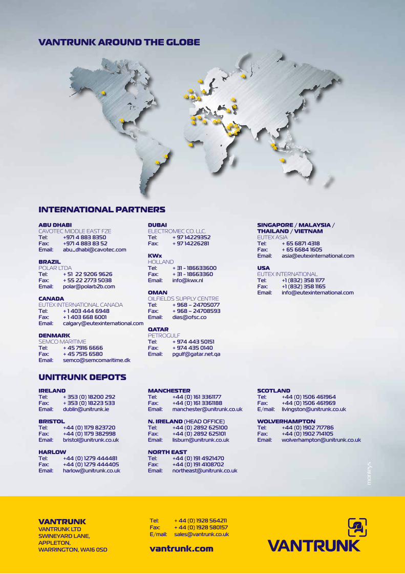
VantRUnK aROUnd thE GlOBE
vantrunk.com
VantRUnKVAntRUnk LtdSWInEyARd LAnE,AppLEton,WARRIngton, WA16 0Sd
tel: + 44 (0) 1928 564211Fax: + 44 (0) 1928 580157E/mail: [email protected]
aBU dhaBiCAvOTEC MIDDLE EAST FZEtel: +971 4 883 8350Fax: +971 4 883 83 52Email: [email protected]
BRaZilPOLAr LTDAtel: + 51 22 9206 9626Fax: + 55 22 2773 5038Email: [email protected]
canadaEuTEX INTErNATIONAL CANADAtel: + 1 403 444 6948Fax: + 1 403 668 6001Email: [email protected]
dEnMaRKSEMCO MArITIMEtel: + 45 7916 6666Fax: + 45 7515 6580Email: [email protected]
dUBaiELECTrOMEC CO. LLC.tel: + 97 14229352Fax: + 97 14226281
KwxhOLLANDtel: + 31 - 186633600Fax: + 31 - 18663360Email: [email protected]
OManOILFIELDS SuPPLY CENTrEtel: + 968 – 24705077Fax: + 968 – 24708593Email: [email protected]
QataRPETrOGuLFtel: + 974 443 50151Fax: + 974 435 0140Email: [email protected]
SinGapORE / MalaySia /thailand / ViEtnaMEuTEX ASIAtel: + 65 6871 4318 Fax: + 65 6684 1605Email: [email protected]
USaEuTEX INTErNATIONALtel: +1 (832) 358 1177Fax: +1 (832) 358 1165Email: [email protected]
intERnatiOnal paRtnERS
UnitRUnK dEpOtS
iRElandtel: + 353 (0) 18200 292Fax: + 353 (0) 18223 533Email: [email protected]
BRiStOltel: +44 (0) 1179 823720Fax: +44 (0) 1179 382998Email: [email protected]
haRlOwtel: +44 (0) 1279 444481Fax: +44 (0) 1279 444405 Email: [email protected]
ManchEStERtel: +44 (0) 161 3361177 Fax: +44 (0) 161 3361188 Email: [email protected]
n. iREland (HEAd oFFICE)tel: +44 (0) 2892 625100 Fax: +44 (0) 2892 625101 Email: [email protected]
nORth EaSttel: +44 (0) 191 4921470Fax: +44 (0) 191 4108702Email: [email protected]
ScOtlandtel: +44 (0) 1506 461964Fax: +44 (0) 1506 461969E/mail: [email protected]
wOlVERhaMptOntel: +44 (0) 1902 717786 Fax: +44 (0) 1902 714105Email: [email protected]