Embed Size (px)
Citation preview
Three Point Bending with HyperMesh - RD-3595
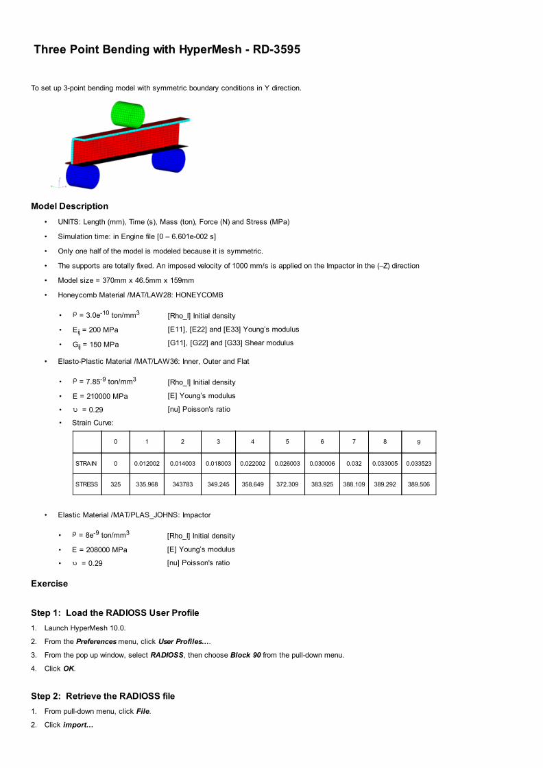
To set up 3-point bending model with symmetric boundary conditions in Y direction.
Model Description
• UNITS: Length (mm), Time (s), Mass (ton), Force (N) and Stress (MPa)
• Simulation time: in Engine file [0 – 6.601e-002 s]
• Only one half of the model is modeled because it is symmetric.
• The supports are totally fixed. An imposed velocity of 1000 mm/s is applied on the Impactor in the (–Z) direction
• Model size = 370mm x 46.5mm x 159mm
• Honeycomb Material /MAT/LAW28: HONEYCOMB
• = 3.0e-10 ton/mm3
• Eij = 200 MPa
• Gij = 150 MPa
[Rho_I] Initial density
[E11], [E22] and [E33] Young’s modulus
[G11], [G22] and [G33] Shear modulus
• Elasto-Plastic Material /MAT/LAW36: Inner, Outer and Flat
• = 7.85-9 ton/mm3
• E = 210000 MPa
• = 0.29
[Rho_I] Initial density
[E] Young’s modulus
[nu] Poisson's ratio
• Strain Curve:
0 1 2 3 4 5 6 7 8 9
STRAIN 0 0.012002 0.014003 0.018003 0.022002 0.026003 0.030006 0.032 0.033005 0.033523
STRESS 325 335.968 343783 349.245 358.649 372.309 383.925 388.109 389.292 389.506
• Elastic Material /MAT/PLAS_JOHNS: Impactor
• = 8e-9 ton/mm3
• E = 208000 MPa
• = 0.29
[Rho_I] Initial density
[E] Young’s modulus
[nu] Poisson's ratio
Exercise
Step 1: Load the RADIOSS User Profile
1. Launch HyperMesh 10.0.
2. From the Preferences menu, click User Profiles….
3. From the pop up window, select RADIOSS, then choose Block 90 from the pull-down menu.
4. Click OK.
Step 2: Retrieve the RADIOSS file
1. From pull-down menu, click File.
2. Click import…
3. Click File, navigate to the correct directory, and select BENDING_0000.rad.
4. Click Apply.
5. Click Close to close the window.
Step 3: Create and Assign material and property for FOAM
1. On the Collectors menu, click Edit and select Components subpanel or from the toolbar click on component icon and go to the Updatepage.
2. Click on comps and select Foam.
3. Make sure card image = is set to Part.
4. Click on create mat tab to create material.
5. For mat name =, enter Foam.
6. Set type = to OTHER.
7. For card image = select M28_HONEYCOMB.
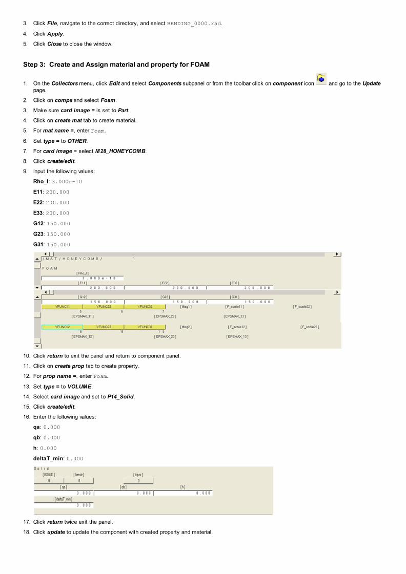
8. Click create/edit.
9. Input the following values:
Rho_I: 3.000e-10
E11: 200.000
E22: 200.000
E33: 200.000
G12: 150.000
G23: 150.000
G31: 150.000
10. Click return to exit the panel and return to component panel.
11. Click on create prop tab to create property.
12. For prop name =, enter Foam.
13. Set type = to VOLUME.
14. Select card image and set to P14_Solid.
15. Click create/edit.
16. Enter the following values:
qa: 0.000
qb: 0.000
h: 0.000
deltaT_min: 0.000
17. Click return twice exit the panel.
18. Click update to update the component with created property and material.

Step 4: Create and Assign material and property for the component Inner
1. On the Collectors menu, click Edit and select Components subpanel or from the toolbar, click on component icon and go to the Updatepage.
2. Click on comps and select Inner.
3. Make sure card image = is set to Part.
4. Click on create mat tab to create material.
5. For mat name=, enter Inner.
6. For type =, select ELASTO-PLASTIC.
7. For card image = select M36_PLAS_TAB .
8. Click create/edit.
9. Input the following values:
Rho_I: 7.85e-09
E: 210000.000
nu: 0.290
EPS_max: 0.000
EPS_t1: 0.000
C_hard: 0.000
Fcut: 0.000
Epsilon_F: 0.000
alpha1: 1.000
10. Click return to exit the panel and return to component panel.
11. Click on create prop tab to create property.
12. For prop name =, enter Inner.
13. Set type = to SURFACE.
14. For card image =, select P1_SHELL.
15. For thickness=, enter 9.119e-01.
16. Click create/edit.
17. Enter the following values:
Hm: 0.00
Hf: 0.00
Hr: 0.00
Dm: 0.00
Thick: 9.119e-01
Ashear: 0.000
18. Click return to exit the panel.
19. Click update to update the component with created property and material.
Step 5: Create and Assign material and property for the components Outer

1. On the Collectors menu, click Edit and select Components subpanel or from the toolbar click on component icon and go to the Updatepage.
2. Click on comps and select Outer.
3. Make sure card image = is set to Part.
4. Click on create mat tab to create material.
5. For mat name=, enter Outer.
6. For type =, select ELASTO-PLASTIC.
7. Change the card image = to same as and pick Inner.
8. Click create to create material Outer with same values as material Inner.
9. Click return to return to the component panel.
10. Click on create prop tab to create property.
11. For prop name =, enter Outer.
12. Set type = to SURFACE.
13. Change the card image = to same as and pick Inner.
14. Click create to create property Outer with same values as property Inner.
15. Click return to return to the component panel.
16. Click update to update the component with created property and material.
Step 6: Create and Assign material and property for the components Flat
Follow the procedure described in Step 5 with Outer replaced by Flat.
Step 7: Create and assign material and property for Impactor
1. On the Collectors menu, click Edit and select Components subpanel or from the toolbar click on component icon and go to the Update
page.
2. Click on comps and select Impactor.
3. Make sure card image = is set to Part.
4. Click on create mat tab to create material.
5. For mat name=, enter Impactor.
6. For type =, select ELASTIC.
7. For card image =, select M1_ELAST.
8. Click create/edit.
9. Input the following values:
Rho_I: 8.000e–09
Ref_Rho: 0.000
E: 208000.000
nu: 0.290
10. Click return to return to the component menu.
11. Click on create prop tab to create property.
12. For prop name =, enter Impactor.
13. Set type = to SURFACE.
14. Change the card image = to same as and pick Inner.
15. Click create to create material Outer with same values are material Inner.
16. Click return to return to the component panel.
17. Click update to update the component with created property and material.

Step 8: Create and assign material and property for Support
Follow the same procedures as in Step 5. Create a copy of Impactor property and material with name support and assign it to component support.
After completing Step 8, open the component view of the model browser or component table to check the correct assignment.
Step 9: Create a rigid body to make Impactor and Support Rigid
1. On the toolbar, click collector panel ( ).
2. Go to create subpanel.
3. For name=, enter Impact rigid.
4. Select any color for easy visualization.
5. Switch to no card image.
6. Switch to no property.
7. Click create.
8. Click return to exit the panel.
9. Go to 1D page, go to the rigids panel.
10. Ensure that you are in the create sub-panel.
11. For dependent switch to comps.
12. For primary node switch calculate node.
13. Click comps.
14. Select Impactor, then click select.
15. Click create.
16. Click return to exit the panel.
17. Similarly, create rigid body for Support component in a collector with the name “Support rigid” using sub-Steps 7.1 to 7.13.
Step 10: Define imposed velocity and boundary condition for the impactor
1. From the Utility page, start the BC’s Manager.
2. For Name, enter IMPOSED_VELOCITY, set Select type to Imposed velocity and set the GRNOD to Nodes.
3. Click nodes and select the master node of the rigid body as shown in the following image.

4. Set the Direction as Z.
5. Set Scale Y to -1000.0 as the direction of velocity is opposite to the global Z axis.
6. Set the Curve ID to Select curve .
7. Select the predefined curve to Func1.
8. Click create to create the imposed velocity boundary condition.
9. For Name, enter Impactor_constraints, set Select type to Boundary condition and set the GRNOD to Nodes.
10. Click nodes and select the master node of the rigid body.
11. Check all the degrees of freedom to constrain, except Tz.
12. Click create to create the boundary condition.
Step 11: Define fixed boundary condition for the support
1. From the Utility page, start the BC’s Manager.
2. For Name, enter support_fixed, set Select type to Boundary condition and set the GRNOD to Nodes.
3. Select the master node of the rigid body created on Supporter as shown in the following image.
4. Check all the degrees of freedom to constraint.
5. Click create to create the boundary condition.

Step 12: Define symmetry boundary condition for the foam, inner, outer and flat
1. From the Utility page, start the BC’s Manager.
2. For Name, enter SYMMETRY_XZ, set Select type to Boundary condition and set the GRNOD to Nodes.
3. Select the nodes of the foam, inner, outer and flat as shown in the following image.
4. Check the degrees of translational degrees of freedom Y and rotational degrees of freedom X and Z to constraint.
5. Click create to create the boundary condition.

6. Click close to exit the BC Manager.
Step 13: Define contacts between the beam and the support
1. Enter the interfaces panel or from Tools Create cards Inter Type 7.
2. For name =, enter Support.
3. Set type = to TYPE7.
4. Click create.
5. Go to the add sub-panel.
6. Switch master selector to comps.
7. Click the yellow comps button.
8. From the list of comps, select Support.
9. Click select update.
10. Set the slave selector to comps.
11. Click the yellow comps button.
12. Select the component FLAT.
13. Click select update.
14. Go to the card image sub-panel.
15. Click edit.
16. Enter the values as in the following image:
17. Click return twice to exit the panel.
Step 14: Define contacts between the impactor and the outer
1. From Analysis page interfaces panel create sub-panel.
2. For name =, enter Imp_Outer.
3. Set type = to TYPE7.
4. Click create.
5. Go to the add sub-panel.
6. For master, select comps.
7. Click the yellow comps button.
8. From the list of comps, select Impactor.

9. Click select update.
10. For slave, select sets.
11. Click the yellow sets button.
12. From the list of comps, select Outer created previously.
13. Click select update.
14. Go to the card image sub-panel and click edit.
15. Click return twice to exit the panel.
Step 15: Define the self contact between the beam components
1. From the Analysis page, enter the interfaces panel, create sub-panel.
2. For name =, enter Self.
3. Set type = to TYPE7.
4. Click create.
5. Go to the add sub-panel.
6. Set the master selector to comps.
7. Click the yellow comps button.
8. From the list of comps, select Inner, Outer, and Flat.
9. Click select update.
10. Set the slave selector to comps.
11. Click the yellow comps button.
12. From the list of comps, select Inner, Outer, and Flat.
13. Click select update.
14. Go to card image subpanel.
15. Click edit.
Enter values as shown in the following image:
16. Click return twice to exit the panel.
Step 16: Create Interface time history
1. Go to Analysis page, then output block panel.
2. For name=, enter IMPACTOR.
3. Switch the entity selector to groups.
4. Click groups and select the interface Imp_Outer from the list.
5. Click select create edit.
6. For VAR field, enter DEF
7. Click return twice to exit the panel.
Step 17: Allocate Required Memory

1. From the main menu, go to the Analysis page Control Cards sub-panel.
2. Click MemoryReq.
3. Click NMOTS and enter 20000 as depicted in the following image.
Step 18: Create output requests on control cards
1. In the Utility Browser RADIOSS Tools menu page, click Engine File.
Enter the values as shown in each of the windows:

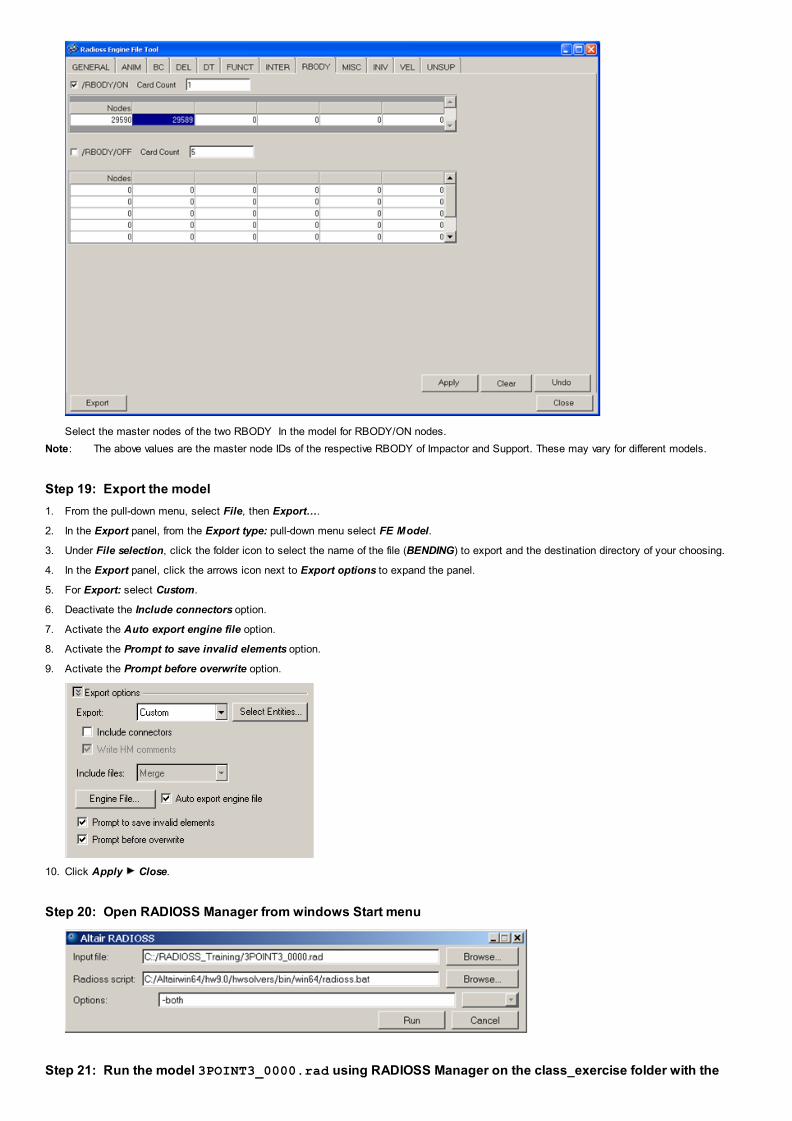
Select the master nodes of the two RBODY In the model for RBODY/ON nodes.
Note: The above values are the master node IDs of the respective RBODY of Impactor and Support. These may vary for different models.
Step 19: Export the model
1. From the pull-down menu, select File, then Export….
2. In the Export panel, from the Export type: pull-down menu select FE Model.
3. Under File selection, click the folder icon to select the name of the file (BENDING) to export and the destination directory of your choosing.
4. In the Export panel, click the arrows icon next to Export options to expand the panel.
5. For Export: select Custom.
6. Deactivate the Include connectors option.
7. Activate the Auto export engine file option.
8. Activate the Prompt to save invalid elements option.
9. Activate the Prompt before overwrite option.
10. Click Apply Close.
Step 20: Open RADIOSS Manager from windows Start menu
Step 21: Run the model 3POINT3_0000.rad using RADIOSS Manager on the class_exercise folder with the

option: –both
Step 22: Review the listing files for this run and verify on the results
1. See if there are any warnings or errors in .out files.
2. Using HyperView, plot the displacement, strain contour and vectors.
EXERCISE EXPECTED RESULTS
von Mises Stress Contour (MPa)
Plastic Strain Contour

Contact Force for Impactor Interface
Go To
RADIOSS, MotionSolve, and OptiStruct Tutorials