Embed Size (px)
Citation preview
January, 1 978 Supersedes A.D. 38-727 pages 1 -2, dated October 1 977
Mailed to: E, D, C/1 994/DB
Selection and Application The Westinghouse automatic vacuum circuit recloser provides three-phase overcurrent protection for both substation and line application. The recloser uses oil as a dielectric in order to minimize space. This application data divides the complete recloser into three separate components for discussion:
1 . The recloser which consists of the high voltage components and stored energy mechanism.
2. The control- Westinghouse type CO overcu rrent relays or MTR static control.
3. The frame, either adjustable substation frame or pole-type mounting frame, and the tank lifting windlass.
Westinghouse Electric Corporation Distribution Apparatus Division Bloomington, Indiana 47401
Relay and Static Control 1 5.5-38 Kv, 800 Amperes 1 1 0, 1 25, or 1 50 Kv BIL
Selection Step 1 - Recloser Continuous Current and Interrupting Rating Select recloser catalog number from Table I below.
Description- The recloser high voltage components and mechanism consist of the following:
• Aluminum top casting- The top casting supports the bushings with the vacuum interrupters.
• High-voltage oil-filled compartment The tank is constructed of fabricated steel. The gasket between top casting and the tank prevents entrance of moisture. Venting is not required since no arcing occurs outside the vacuum envelope.
Application Data 38-727
Page 1
Three-Phase Automatic Vacuum Recloser Type ESV
• Oil drain, sample valve, and visual floating ball oil level indicator.
• Stored energy trip and close mechanism.
• Operations counter and main contact position indicator.
• Manual close pushbutton- The stored energy mechanism permits the recloser to be closed into a faulted line without damage.
• External manual trip lever.
Table 1 Specific Ratings and Catalog Number
Catalog Number ESV 1 51 2 ESV 271 0 ESV 271 2 ESV 3806 ESV 381 0
Rated Maximum Voltage kV, Grounded Wye Systems 1 5.5
Continuous Current Amps 800
Basic Impulse Level Withstand Voltage kV (BIL) 1 1 0
Maximum Interrupting Capacity RMS Symm. Amps@ 1 2,000
60 Hertz, One Minute Withstand, Dry, kV RMS 50
60 Hertz, Ten Second Withstand, Wet, kV RMS 45
Temperature Range
Minimum Close Time, Cycles 25
Minimum Interrupting Time, Cycles 3.5
<D BIL determined by bushing selected. ® Interrupting capacity is not a function of phase or ground minimum trip selection. @ Higher values apply to 150 kV BIL design.
27
800
1 25 or 1 50CD
1 0,000
60!70@
50/60@
25
3.5
27 38 38
800 800 800
1 2 5 or 1 50CD 1 50 1 50
1 2 ,000 6,000 1 0,000
60!70@ 70 70
50/60@ 60 60
25 25 25
3.5 3.5 3.5
www . El
ectric
alPar
tMan
uals
. com
Page 2
Selection Step 2- High Voltage Bushings and Terminals
Description High voltage bushings for the type ESV recloser are of bulk porcelain construction. Terminals supplied are either a NEMA 4-hole flat pad or a 4 bolt clamp type for 2/0 through 800 MCM conductor. All bushings are ASA 70 Grey.
Selection Step 3- Bushing Current Transformers and Auxiliary Switch
Bushing Electrical Characteristics and Catalog Number
Creep Strike BIL Recloser Type Outline ln. ln. Drawing
27.5 10.75 125 Kv ESV 6483A96 27.5 10.75 125 Kv ESV 6483A97 30.5 15.75 150 Kv ESV 6483A98 30.5 15.75 150 Kv ESV 6483A99
Terminal Catalog Number
Clamp #2- 800 MCM ESV 27C NEMA 4 Hole Pad ESV 27P Clamp #2 -800 MCM ESV30C NEMA 4 Hole Pad ESV30P
Description Bushing Current Transformer Technical Data and Catalog Number Each relayed recloser uses a set of three (600/5 or 1 200/5) multi-ratio (5 1ead) bushing current transformers to provide overcu rrent sensing and auxiliary functions such as driving thermal demand ammeters. The recloser with the MTR static control uses a set of three (1 000/5) bushing current transformers to provide overcurrent sensing. Bushing current transformers (2 sets maximum) are mounted on bushings 2-4 and 6. Leads from the BCT's are terminated in the low voltage mechanism compartment with Penn Union 6006-SC short circuiting type term ina I blocks. Each recloser requires 3 "A" and 3 "B" contacts to operate the control circuit. One "A" and one "B" (field changeable) are provided for customer use. (For additional contacts see Selection Step 1 4.)
Selection Step 4- Trip Coil Voltage and Trip Potential Source
Each recloser requires a shunt trip coil. Selection depends upon trip source specified by the user. The users trip control voltage and trip coil voltage must be the same (except when the capacitor trip device or battery trip device is specified). The trip coils will operate from the following sources: • 24 VDC NiCad battery and battery chargerinternal source
Capacitor trip device- internal source 48 or 1 25 VDC- external source 240 VAC- external source
60015, Accuracy Class C100, Curve 511800
Current Ratio 60015 500/5 45015 40015 300/5 25015 20015 15015 100/5 5015 Turns Ratio 120:1 100:1 90:1 80:1 60:1 50:1 40:1 30:1 20:1 10:1
120015, Accuracy Class C200, Curve 511801
Current Ratio 120015 1000/5 90015 800/5 60015 50015 40015 30015 20015 10015 Turns Ratio 240:1 200:1 180:1 160:1 120:1 100:1 80:1 60:1 40:1 20:1
Secondary Trips X2-X3 X1-X2 X1-X3 X4-X5 X3-X4 X2-X4 X1-X4 X3-X5 X2-X5 X1-X5
Catalog Number- Bushing Current Transformer
Quantity and Ratio For Use with Mechanism Cabinet Connection Diagram Catalog Number Control Shown
3-60015 Relay 1885B14 3CT6V 3-120015 Relay 1885B16 3CT12V 6-60015 Relay 1885B15 6CT6V 6-120015 Relay 1885B17 6CT12V 3-60015 and 3-120015 Relay 1885B18 6CT612V
3-100015 Static 1885B19 3CT10V 3-1 00015 and 3-60015 Static 1885B20 6CT610V 3-100015 and 3-120015 Static 1885B21 3CT112V
Note 1: Maximum of 2 sets of BCT's may be specified (6 BCT'slrecloser).
Note2: By selecting catalog numbers for BCT's, the mechanism connection diagram is also selected. This diagram shows the BCT connections and compartment 25 watt, 240 VAC space heater.
Note 3: Ammeters or thermals from accessories, page 8, require 60015 or 120015 BCT's, Size 2 (G03 or G04) cabinet is also required when ammeters or thermals are specified.
Trip Coil Technical Data and Catalog Number
Voltage Trip Voltage Catalog Number Amps Range
24VDC 4.0 14-28 TCE24G01 48 VDC 2.6 28-56 TCE48G01
125 VDC 5.0 70-140 TCE125G01 240 VAC 1.9 208-254 TCE230G01 Cap. Trip Device Ref. Coil 3.7 IL 38721-5 CTDEG02
Note 1: When internal battery trip device (Step 12) is selected specify TCE24G01 24 VDC trip coil.
Note 2: TCE230G01 or TCE24G01 are standard for static control; however, any tripping source can be used.
Selection Step 5- Stored Energy Charging Motor
Description Each recloser is supplied with a spring trip, spring close mechanism. The mechanism requires a 240 VAC motor to charge the closing springs.
Charge Motor Technical Data and Catalog Number
Catalog Number
23ACEG01
Voltage
Nominal 240 VAC Range 208-254 VAC
Locked Rotor Amps
6
Charge Amps
www . El
ectric
alPar
tMan
uals
. com
Selection Step 6- Substation Type Mounting Frame and Control Cabinet Location
Description All substation mounting frames are constructed from 3 in x 3 in x 3/16 in galvanized steel. All frames are adjustable height and include provisions for user grounding.
Note 1: A size 2, G03, frame and cabinet can be supplied on static controlled reclosers where a larger cabinet is required; however, the connection between the control cabinet and the recloser mechanism cabinet will be hard wiring.
Note 2: The size one cabinet (G05) is the standard substation frame and cabinet for a static controlled recloser. If metering accessories from page 8 are specified, the size 2 cabinet (either the G03 or G04 frame) must be specified depending on whether or not the convenience of a plug connection is required.
Note 3: A size 3 cabinet may be required if several accessories are specified. No catalog numbers apply.
Selection Step 7- Tank Lifting Windlass For Substation Mounted Type ESV Reclosers
Description A winch type tank lifter and the necessary pulleys and cable are supplied so that the user may lower the oil tank for inspection.
Catalog Number
TLSG02
For Use With Type Recloser
ESV All Ratings
Outline Drawing
6485A24
Frame Catalog Normally Used Number for With Listed Cabinet ESV Recloser Control Size
ESVSG03 Relay ESVSG04 Static ESVSG05 Static
ESVSRG03 Relay 2 ESVSRG04 Static 2 ESVSRG05 Static 1
ESVSLG03 Relay ESVSLG04 Static ESVSLG05 Static
Selection Step 8 - Pole Type Mounting Frames For Direct Pole Mounting
Description The direct pole mounting frame is constructed with 3 in x 3 in x 3/16 in galvanized steel. Frames with tanklifters include a gear box type tank lifter, and the necessary pulleys and cables so the user may lower the oil tank for inspection.
Catalog For Use With Outline Number Type Recloser Drawing
ESVPG01 Relayed ESV with 6484A87 Size 2 Cabinet without tanklifter<D
ESVPG02 Static ESV with 6484A87 Size 1 Cabinet without tanklifter<D
ESVPLG01 Relayed ESV with 6485A15 Size 2 Cabinet with tanklifter
ESVPLG02 Static ESV with 6485A15 Size 1 Cabinet with tanklifter
CD Tanklifters cannot be added to this design.
Application Data 38-727
Page 3
Cabinet Position Bushing 1, 3, and 5 To Front
Front Recessed Front Recessed Front Recessed
Rear Mounted Rear Mounted Rear Mounted
Left Side Left Side Left Side
Wiring Method Outline Between Control Drawing Cabinet and Mechanism Cabinet
Hard Wire 6483A90 Am phenol plugs 6483A90 Am phenol plugs 6483A91
Hard Wire 6483A92 Am phenol plugs 6483A92 Amphenol plugs 6483A93
Hard Wire 6483A94 Am phenol plugs 6483A94 Am phenol plugs 6483A95
Selection Step 10- Control Cable Assembly For Use With Pole Mounted Reclosers
Description Each recloser and control cabinet are connected together via a multi-conductor control cable. For pole mounted type ESV reclosers the user must specify the length of cable required. The control cable enters the recloser mechanism cabinet through a multiconductor plug and jack. Control cable selection is not required for substation mounted units.
Catalog Number
CA5G01 CA10G01 CA15G01 CA20G01 CA25G01 CA30G01 CA35G01 CA40G01
Length of Control Cable (Feet)CD
5 10 15 20 25 30 35 40
CD Actual length of the cable is length shown plus 5 ft. for slack.
www . El
ectric
alPar
tMan
uals
. com

Page 4
Selection Step 11 - Relay Control For Either Substation or Pole Mounted Reclosers
Description Recloser applications may be simplified through use of Westinghouse Type CO overcurrent relays for phase and ground protection. Westinghouse Type CO relays provide an infinite number of time delay trip curves and when combined with the multiratio bushing current transformer provide the user with many values of phase and ground minimum trip settings without the purchase of any other components. For complete curve shapes, time delay current ranges, and instantaneous current ranges refer to Westinghouse Performance Data 41 -000 and DB 4 1 -1 00A.
Typical BCT-Relay Connections For Grounded Wye Systems
3 Phase Relays and 1 Ground Relay ¢A----------------���-----¢B---------+��--------�------¢C -f�L...t---=---+-------+-----
GND
Type of 3 Phase Relays and Fault 1 Ground Relay
Control Cabinet Description The relay size 2 control cabinet is mounted on the substation frame (See Selection Step 6 for location) or provided with pole mounting brackets in the case of a pole mounted unit. All relays and controls are mounted on a hinged front panel for easy access. Each relay control package is supplied with the following equipment as standard.
• Control switch with red and green indicating lights.
Fuse for control circuit protection. Non-reclose switch. 25 watt, 230 VAC control cabinet heater. Necessary terminal blocks and control wir-
ing.
2 Phase Relays and 1 Ground Relay ¢A ---------------��+-------¢8 --------���-------+-------¢C ���--�--,_------+--------
GND
2 Phase Relays and 1 Ground Relay
Primary Back-Up Primary Back-Up Trip Relay Trip Relay
;_�A-GND GND i)A 0B-GND GND i)B i)C-GND GND 0C (lA-0B (]A or08 0·B or 0A 0A -0C 0Aor0C (_)C or 0A �K-0B 0C or ;:_)8 j._lB or0C
0A &i)B-GND GND 0A or0B 0A & i)C-GND GND 0A or0C 0B &0C-GND GND 08 or 0C 0A. j._J8, 0C-GND GND 0Aor0B or.()C
Note 1: The above table is designed to illustrate a general case. Actual primary and back -up tripping depend upon relay co-ordination, fault current magnitude, and symmetry.
Trip Relay Trip Relay
GND i)A GND GND i)C
0A �1A or0C 0C or0A )<_)( GND i)A GND 0Aor0C GND 0C GND 0A orViC
Relay Selection The relay control package may be supplied with two phase and one ground relay, three phase relays and no ground relay, or three phase relays and one ground relay. The phase and ground relays may be supplied with or without a fast trip feature. Each relay and its associated fast trip relay contain "targets" to indicate which phase has "seen" a fault. Each relay is mounted in a Westinghouse Flexi-test case to permit quick removal for inspection and maintenance. The control scheme requires circuit closing (CC) type relays. Refer to DB 41-000 or Table 4, page 7, for style number selection.
The use of two phase and one ground relays, three phase relays and no ground relay, or three phase relays and one ground relay depend upon the application and/or user preference. The following table is designed to show the tripping sequence for various combinations of fault conditions.
3 Phase Relays and No Ground Relay ¢A---------------��;-------¢B---------+��--�--�-------¢C���--�--�------;-------
¢A
3 Phase Relays and No Ground Relay
Primary Back-Up Trip Relay Trip Relay
0A ,ZB i)C
0A ori)B 0B or0A 0A or0C 0C or0A 0C or 0B 0B or 0C 0A or0B 0B or0A 0A or;_7)C 0C or0A )2)8 or 0C 0C or08
0A or08or0C 0C or 08or 0A
www . El
ectric
alPar
tMan
uals
. com
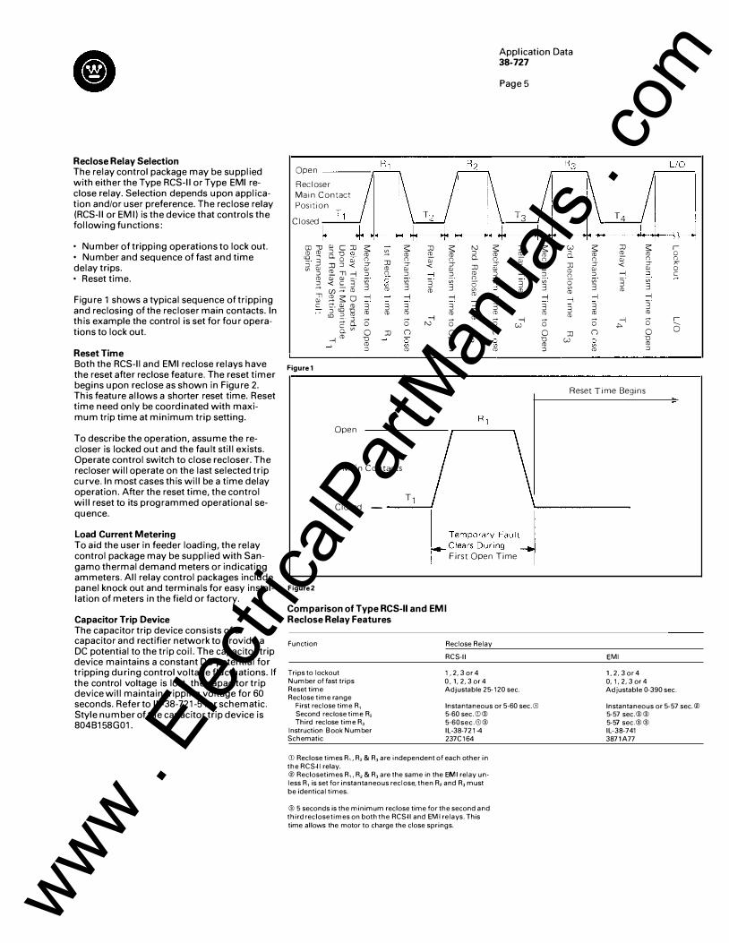
Reclose Relay Selection The relay control package may be supplied with either the Type RCS-11 or Type EMI reclose relay. Selection depends upon application and/or user preference. The reclose relay (RCS-11 or EM I) is the device that controls the following functions:
• Number of tripping operations to lock out. • Number and sequence of fast and time delay trips. • Reset time.
Figure 1 shows a typical sequence of tripping and reclosing of the recloser main contacts. In this example the control is set for four operations to lock out.
Reset Time Both the RCS-11 and EMI reclose relays have the reset after reclose feature. The reset timer begins upon reclose as shown in Figure 2. This feature allows a shorter reset time. Reset time need only be coordinated with maximum trip time at minimum trip setting.
To describe the operation, assume the recloser is locked out and the fault still exists. Operate control switch to close recloser. The recloser will operate on the last selected trip curve. In most cases this will be a time delay operation. After the reset time, the control will reset to its programmed operational sequence.
Load Current Metering To aid the user in feeder loading, the relay control package may be supplied with Sangamo thermal demand meters or indicating ammeters. All relay control packages include panel knock out and terminals for easy installation of meters in the field or factory.
Capacitor Trip Device The capacitor trip device consists of a capacitor and rectifier network to provide a DC potential to the trip coil. The capacitor trip device maintains a constant DC potential for tripping during control voltage fluctuations. If the control voltage is lost, the capacitor trip device will maintain tripping voltage for 60 seconds. Refer to IL-38-721-5 for schematic. Style number of the capacitor trip device is 804B158G01.
Open
Recloser
Main Contact
Position
Closed
co-o QJ C:JJ s s :JJ s "' (!) (!) :::J D (1) (!) � (!) 'E.. (!) "' � 0.0 QJ 0 0 QJ 0 - 3 ::r :JJ ::r ::r � QJ :JJ:::l < < 'E.."Tl-1
QJ (!) QJ QJ :::J :::J 0 :::J -1 :::J (1) Q) ill -· 3 :;: 3 3 2. < ":..3 3
(/)� (!) ro (!) "Tl �so -1 -1 -1 -1 QJ c g-� � 3 3 3 3
"' :::J (!) (!) (!) ro (!) -· :J 0 0 -1 0 �o. N §_"' 0 :JJ n 0
-1(!) D :;: D
(!) (1) :::J (!) :J
Figurel
N s :::J (!) 0. 0 ::r :JJ QJ (1) :::J Q. 3 :;: (!) -1 -1 3 3 (!) (!) 0 :JJ n
N :;: (1)
Application Data 38-727
Page 5
T3
s w (1) 0. 0 ::r :JJ QJ (!) :::J 0
:JJ 'E.. QJ < -1
3 0 "' (!)
3 (!)
-1 -1 3 3 (1) (!) 0 -1 w 0 :JJ D (!)
w :::J
T4
s :JJ (!) 'E.. 0 QJ ::r < QJ :::J -1
3 3 (1) -1
3 (!)
0 -1 �
n
:;: (!)
s (1) (") ::r QJ :::J 3 -1 3 (!)
0 0 D (!) :::J
r 0 (") " 0 c
r 0
Reset Time Begins
Open
T1 \ Main Contacts
Closed - -------!
I g,:�,���:,'"" I r- First Open Time 1 Figure2
Comparison of Type RCS-11 and EMI Reclose Relay Features
Function
Trips to lockout Number of fast trips Reset time Reclose time range
First reclose time R1 Second reclose time R2 Third reclose time R3
Instruction Book Number Schematic
Reclose Relay
RCS- 11
1, 2, 3 or 4 0 , 1, 2,3 or 4 Adjustable 25- 120 sec.
Instantaneous or 5 -60 sec. CD 5-60 sec.CD@ 5 -60sec.CD@ IL -38-72 1·4 237C 164
CD Reclose times R1, R2 & R3 are independent of each other in the RCS-11 relay. ® Reclosetimes R1, R2 & R3 are the same in the EMI relay unless R1 is set for instantaneous reclose, then R2 and R3 must be identical times.
® 5 seconds is the minimum reclose time for the second and third reclose times on both the RCS-11 and EMI relays. This time allows the motor to charge the close springs.
EMI
1 ,2, 3 or 4 0, 1, 2, 3 or 4 Adjustable 0-390 sec.
Instantaneous or 5-57 sec.® 5-57 sec.@@ 5-57 sec.@@ IL-38-741 3871A77
www . El
ectric
alPar
tMan
uals
. com
Page 6
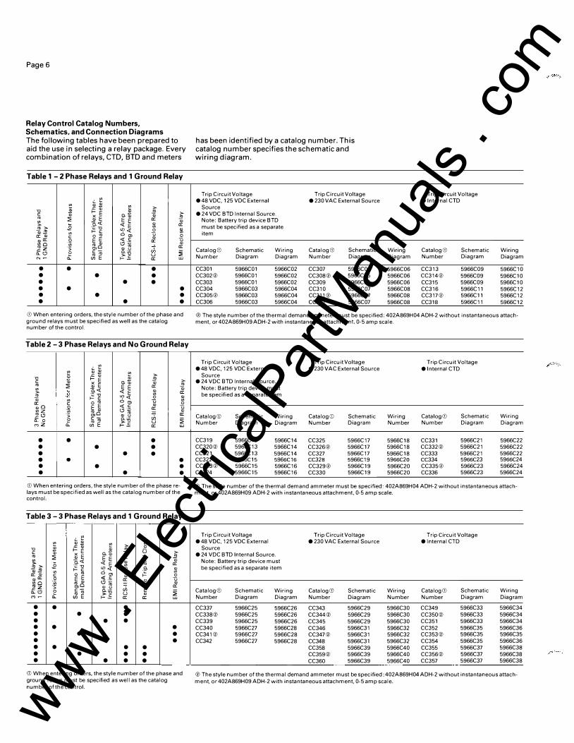
Relay Control Catalog Numbers, Schematics, and Connection Diagrams The following tables have been prepared to aid the use in selecting a relay package. Every combination of relays, CTD, BTD and meters
Table 1 - 2 Phase Relays and 1 Ground Relay
�� "' "' � $ .<::" ii; "0 >- E � c " "-" a:; rn :;;: iii E E E a: a:; "' Q_<( " > <( E a: rn > .2 -� "'C "'
ai..!!:! "' >- c "'<( _Q 1;\ a: " 0 rn 0"' '-' 0 "a: c
E E <( c " u 0 a: "'0 ·;;; rn " f.!J·g " _gz ·:; "'0 " '-' ch a:
0 c- c_·- :;;: o._(.!J .t rn rn >" u
N � "' E r-.E: a: w
• • • • • • • • • • • • • • • • • •
CD When entering orders, the style number of the phase and ground relays must be specified as well as the catalog number of the control.
Table 2- 3 Phase Relays and No Ground Relay
�� "' "' > "0 ii; .<::" i; a; >- E _!'? c "-" " � rn :;;: iii E E E a: a:; "' Q_<( > .2 'i:"' <( E & a: _!'? >- c "'<( 0 & " "' u a: c o rn 0 "' 0 "0 0 E E <(c " u <nZ ·;;; rn " (.?'�
a: " _g<.!J ·:; "'0 " '-' ch a: e c- �13
-o._ 0 rn rn u :;;: roZ o._ "' E r-.E: a: w
• • • • • • • • • • • • • • • • • •
G) When entering orders, the style number of the phase relays must be specified as well as the catalog number of the control.
Table 3- 3 Phase Relays and 1 Ground Relay
�� "' "' & i; .<::" i; > 0 "0 a; >-E rn u c "-" a; � rn :;;: iii E E E a: "0 a:; � Q_<( c rn > .2 'i:"' <(E & rn a: w� >- c "'<( 0 "- " "' o rn 0"' u � "' a: " c " 0 "a: .9 E E <t: .� a: 2 u "'0 "' rn " <.!ll;j - " _gz ·:; "'0 " '-' ch 0 a:
o._(.!J 0 c-g:::o E -
.t rn rn u " :;;: ro� UlE r-.E: a: a: w
• • • • • • • • • • • • • • • • • • • • • • • • • • • • • •
CD When entering orders, the style number of the phase and ground relays must be specified as well as the catalog number of the control.
has been identified by a catalog number. This catalog number specifies the schematic and wiring diagram.
Trip Circuit Voltage Trip Circuit Voltage e48 VDC. 125 VDC External e 230 VAC External Source
Source e 24 VDC BTD Internal Source.
Note: Battery trip device BTD must be specified as a separate item
CatalogGl Schematic Wiring CatalogGl Schematic Number Diagram Diagram Number Diagram
CC301 5966C01 5966C02 CC307 5966C05 CC302® 5966C01 5966C02 CC308® 5966C05 CC303 5966C01 5966C02 CC309 5966C05 CC304 5966C03 5966C04 CC310 5966C07 CC305® 5966C03 5966C04 CC311® 5966C07 CC306 5966C03 5966C04 CC312 5966C07
Trip Circuit Voltage elnternal CTD
Wiring CatalogGl Schematic Wiring Diagram Number Diagram Diagram
5966C06 CC313 5966C09 5966C10 5966C06 CC314® 5966C09 5966C10 5966C06 CC315 5966C09 5966C10 5966C08 CC316 5966C11 5966C12 5966C08 CC317® 5966C11 5966C12 5966C08 CC318 5966C11 5966C12
@The style number of the thermal demand ammeter must be specified: 402A869H04 ADH-2 without instantaneous attachment, or 402A869H09 ADH-2 with instantaneous attachment 0-5 amp scale.
Trip Circuit Voltage Trip Circuit Voltage Trip Circuit Voltage e 48 VDC. 125 VDC External e 230 VAC External Source elnternal CTD
Source e 24 VDC BTD Internal Source.
Note: Battery trip device must be specified as a separate item
Catalog G) Schematic Wiring Catalog G) Schematic Wiring CatalogGJ Schematic Wiring Number Diagram Diagram Number Diagram Number Number Diagram Diagram
CC319 5966C13 5966C14 CC325 5966C17 5966C18 CC331 5966C21 5966C22 CC320® 5966C13 5966C14 CC326® 5966C17 5966C18 CC332® 5966C21 5966C22 CC321 5966C13 5966C14 CC327 5966C17 5966C18 CC333 5966C21 5966C22 CC322 5966C15 5966C 16 CC328 5966C19 5966C20 CC334 5966C23 5966C24 CC323® 5966C15 5966C16 CC329® 5966C19 5966C20 CC335® 5966C23 5966C24 CC324 5966C15 5966C16 CC330 5966C19 5966C20 CC336 5966C23 5966C24
®The style number of the thermal demand ammeter must be specified: 402A869H04 ADH-2 without instantaneous attachment, or 402A869H09 ADH-2 with instantaneous attachment, 0-5 amp scale.
Trip Circuit Voltage Trip Circuit Voltage Trip Circuit Voltage e 48 VDC. 125 VDC External e 230 VAC External Source elnternal CTD
Source e 24 VDC BTD Internal Source.
Note: Battery trip device must be specified as a separate item
CatalogGJ Schematic Wiring CatalogGl Schematic Wiring CatalogGJ Schematic Wiring Number Diagram Diagram Number Diagram Number Number Diagram Diagram
CC337 5966C25 5966C26 CC343 5966C29 5966C30 CC349 5966C33 5966C34 CC338® 5966C25 5966C26 CC344® 5966C29 5966C30 CC350® 5966C33 5966C34 CC339 5966C25 5966C26 CC345 5966C29 5966C30 CC351 5966C33 5966C34 CC340 5966C27 5966C28 CC346 5966C31 5966C32 CC352 5966C35 5966C36 CC341 ® 5966C27 5966C28 CC347® 5966C31 5966C32 CC353® 5966C35 5966C35 CC342 5966C27 5966C28 CC348 5966C31 5966C32 CC354 5966C35 5966C36
CC358 5966C39 5966C40 CC355 5966C37 5966C38 CC359® 5966C39 5966C40 CC356® 5966C37 5966C38 CC360 5966C39 5966C40 CC357 5966C37 5966C38
®The style number of the thermal demand ammeter must be specified: 402A869H04 ADH-2 without instantaneous attachment. or 402A869H09 ADH-2 with instantaneous attachment. 0-5 amp scale.
www . El
ectric
alPar
tMan
uals
. com
Stock Relays In order to provide short shipment, certain overcurrent relays are stocked at Bloomington. A listing is provided to aid the purchaser in specifying a recloser using stock relays.
Selection Step 12- Battery Trip Device
A battery trip device may be selected. The battery trip device consists of a 24 VDC Ni-CAD battery and a 230 VAC potential type battery charger.
Catalog Number
BTDG01
Description
Battery trip device for use with control catalog numbers CC301-CC306, CC319-CC324, and CC337-CC342.
Connection Diagram 3889A99
Selection Step 13- Remote Trip and Close
Description All relayed control packages are wired for user addition of a remote trip and close function, except control catalogs CC-355-360 which are furnished with all the local equipment wired at the factory.
This accessory includes the following loose and unmounted material that the user must mount in the recloser control cabinet if a control other than CC355-360 is specified.
628A271 H07 Latch Relay 1 61 A833H07 Remote/Local Switch 1 58P987H01 Remote/Local N/P
In addition- a 505A71 4G01 Remote Switch is supplied for remote mounting by the user.
Note- this option requires 230 VAC power. If other voltages, see Accessories 1 0 and 1 1 , page 4, of PL 38-720.
Catalog Number
STCG01
Description
Remote trip and close, loose and unmounted for 230 VAC remote power operation only on controls other than CC 355-360
Selection Step 14- Extra Auxiliary Switches
Description A total of four extra "A" or "B" contacts may be added for exclusive customer use. This accessory combined with the standard two extra "A" or "B" contacts (see Selection Step
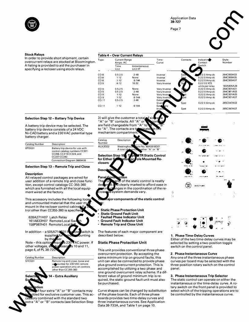
Table 4- Over Current Relays
Type Current Range Amps: AC
Time Instantaneous Unit Unit liT
C0-8 0.5-2.5 2-48 C0-8 1-12 None C0-8 1-12 6-144
Time Curve
Inverse Inverse Inverse
Application Data 38-727
Page 7
Contacts
Spst Spst Spst
Indicating Style Contact Number Switch
0.2/2.0 Amp de 264C900A03 0.2/2.0 Amp de 264C900A05 0.2/2.0 Amp de 264C900A07
C0-9 4-12 16-32 Very Inverse Spst 0.2/2.0 2 ICS units per relay 183A805A28
C0-9 0.5-2.5 None Very Inverse Spst 0.2/2.0 Amp de 264C901A01 C0-9 0.5-2.5 2-48 Very Inverse Spst 0.2/2.0 Amp de 264C901A03 C0-9 1-12 None Very Inverse Spst 0.2/2.0 Amp de 264C901A05 C0-9 1-12 6-144 Very Inverse Spst 0.2/2.0 Amp de 264C901A07 C0-11 0.5-2.5 2-48 Extremely
Inverse C0-11 1-12 6-144 Extremely
Inverse
3) will give the customer a total of six extra "A" or "B" contacts. All "A" or "B" contacts are field changeable from "A" to "B" or "B" to "A". The contacts are terminated in the mechanism compartment.
Catalog Number
AUX3G02
Description
Westinghouse Style No. 46A5916G01 A tota I of 4 contacts either "A" or "8"
Selection Step 15- Type MTR Static Control for Either Substation or Pole Mounted Reclosers
Description
Panel Construction The front panel of the static control is neatly designed and clearly marked to afford ease in making changes in the coordination of the recloser as system demands vary.
The major components of the static control are:
Static Phase Protection Unit Static Ground Fault Unit
• Faulted Phase Indicator Unit Ground Fault Indicator Unit Remote Trip and Close Unit
The features of each major component are described below.
Static Phase Protection Unit
This unit provides conventional three phase overcurrent protection. By accepting the same minimum trip on ground faults, this unit can also be connected to provide phase plus ground overcurrent protection. This is accomplished by utilizing a two phase and one ground overcurrent relay scheme. If a different value of ground minimum trip is required, the static ground fault unit must also be purchased.
Curve shapes can be changed by substitution of the phase boards. Each of three phase boards provides two time-delay curves and three instantaneous curves. See Application Data 38-733A, and Table 1 on page 1 0.
Spst 0.2/2.0 Amp de
Spst 0.2/2.0 Amp de
--
"- •. �-
·•t •
,.,fit • '-JtiiH
:- " .
•
1. Phase Time-Delay Curves
265C047A03
265C047A0 7
•
Either of the two time-delay curves may be selected by setting a two-position toggle switch on the control panel.
2. Phase Instantaneous Curve Any one of the three instantaneous phase curves per board may be selected with the three-position rotary switch on the control panel.
3. Phase Instantaneous Trip Selector The static control can operate on either the instantaneous or the time-delay curve. A rotary switch on the front panel is provided to select which of the tripping operations are to be controlled by the instantaneous curve.
www . El
ectric
alPar
tMan
uals
. com
PageS
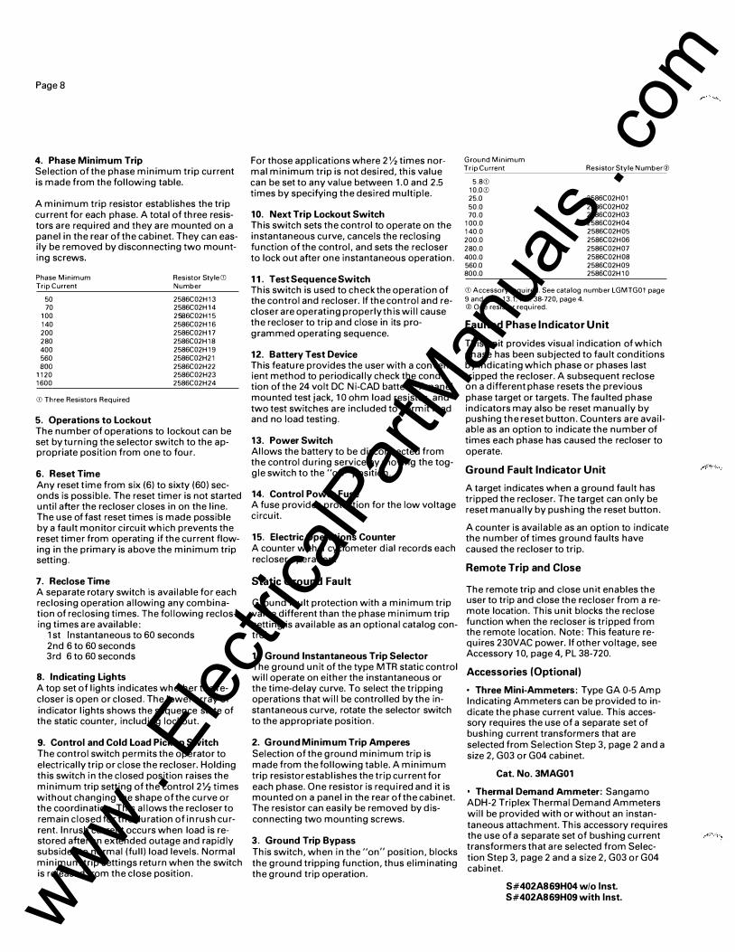
4. Phase Minimum Trip Selection of the phase minimum trip current is made from the following table.
A minimum trip resistor establishes the trip current for each phase. A total of three resistors are required and they are mounted on a panel in the rear of the cabinet. They can easily be removed by disconnecting two mounting screws.
Phase Minimum Trip Current
50 70
100 140 200 280 400 560 BOO
1120 1600
CD Three Resistors Required
5. Operations to Lockout
Resistor Style CD Number
2586C02H13 2586C02H14 2586C02H15 2586C02H16 2586C02H17 2586C02H18 2586C02H19 2586C02H21 2586C02H22 2586C02H23 2586C02H24
The number of operations to lockout can be set by turning the selector switch to the appropriate position from one to four.
6. Reset Time Any reset time from six (6) to sixty (60) seconds is possible. The reset timer is not started until after the recloser closes in on the line. The use of fast reset times is made possible by a fault monitor circuit which prevents the reset timer from operating if the current flowing in the primary is above the minimum trip setting.
7. Reclose Time A separate rotary switch is available for each reclosing operation allowing any combination of reclosing times. The following reclosing times are available:
1 st Instantaneous to 60 seconds 2nd 6 to 60 seconds 3rd 6 to 60 seconds
8. Indicating Lights A top set of lights indicates whether the recloser is open or closed. The lower array of indicator lights shows the sequence state of the static counter, including lockout.
9. Control and Cold Load Pickup Switch The control switch permits the operator to electrically trip or close the recloser. Holding this switch in the closed position raises the minimum trip setting of the control 2'h times without changing the shape of the curve or the coordination. This allows the recloser to remain closed for the duration of inrush current. Inrush current occurs when load is restored after an extended outage and rapidly subsides to normal (full) load levels. Normal minimum trip settings return when the switch is released from the close position.
For those applications where 2'12 times normal minimum trip is not desired, this value can be set to any value between 1 . 0 and 2.5 times by specifying the desired multiple.
10. Next Trip Lockout Switch This switch sets the control to operate on the instantaneous curve, cancels the reclosing function of the control, and sets the recloser to lock out after one instantaneous operation.
11. TestSequenceSwitch This switch is used to check the operation of the control and recloser. If the control and recloser are operating properly this will cause the recloser to trip and close in its programmed operating sequence.
12. Battery Test Device This feature provides the user with a convenient method to periodically check the condition of the 24 volt DC Ni-CAD battery. A panel mounted test jack, 1 0 ohm load resistor, and two test switches are included to permit load and no load testing.
13. Power Switch Allows the battery to be disconnected from the control during service by moving the toggle switch to the "off" position.
Ground Minimum Trip Current
5.8GJ 10.0GJ 25.0 50.0 70.0
100.0 140.0 200.0 280.0 400.0 560.0 800.0
Resistor Style Number®
2586C02H01 2586C02H02 2586C02H03 2586C02H04 2586C02H05 2586C02H06 2586C02H07 2586C02H08 2586C02H09 2586C02H10
GJ Accessory required. See catalog number LGMTG01 page 9 and item 13.1, P.L. 38-720, page 4. @One resistor required.
Faulted Phase Indicator Unit
This unit provides visual indication of which phase has been subjected to fault conditions by indicating which phase or phases last tripped the recloser. A subsequent reclose on a different phase resets the previous phase target or targets. The faulted phase indicators may also be reset manually by pushing the reset button. Counters are available as an option to indicate the number of times each phase has caused the recloser to operate.
Ground Fault Indicator Unit
A target indicates when a ground fault has 14. Control Power Fuse
tripped the recloser. The target can only be A fuse provides protection for the low voltage
reset manually by pushing the reset button. circuit.
15. Electric Operations Counter A counter with a cyclometer dial records each recloser operation.
Static Ground Fault
Ground fault protection with a minimum trip value different than the phase minimum trip setting is available as an optional catalog control.
1. Ground Instantaneous Trip Selector The ground unit of the type MTR static control will operate on either the instantaneous or the time-delay curve. To select the tripping operations that will be controlled by the instantaneous curve, rotate the selector switch to the appropriate position.
2. Ground Minimum Trip Amperes Selection of the ground minimum trip is made from the following table. A minimum trip resistor establishes the trip current for each phase. One resistor is required and it is mounted on a panel in the rear of the cabinet. The resistor can easily be removed by disconnecting two mounting screws.
3. Ground Trip Bypass This switch, when in the "on" position, blocks the ground tripping function, thus eliminating the ground trip operation.
A counter is available as an option to indicate the number of times ground faults have caused the recloser to trip.
Remote Trip and Close
The remote trip and close unit enables the user to trip and close the recloser from a remote location. This unit blocks the reclose function when the recloser is tripped from the remote location. Note: This feature requires 230VAC power. If other voltage, see Accessory 1 0, page 4, PL 38-720.
Accessories (Optional)
• Three Mini-Ammeters: Type GA 0-5 Amp Indicating Ammeters can be provided to indicate the phase current value. This accessory requires the use of a separate set of bushing current transformers that are selected from Selection Step 3, page 2 and a size 2, G03 or G04 cabinet.
Cat. No. 3MAG01
Thermal Demand Ammeter: Sangamo ADH-2 Triplex Thermal Demand Ammeters will be provided with or without an instantaneous attachment. This accessory requires the use of a separate set of bushing current transformers that are selected from Selection Step 3, page 2 and a size 2, G03 or G04 cabinet.
S#402A869H04 w/o lnst. S#402A869H09 with lnst. www .
Elec
tricalP
artM
anua
ls . c
om
• Zone Sequence Control Unit For applications with two static controlled reclosers in series, it is recommended that the recloser nearest the source (upline) be equipped with the zone sequence accessory to maintain the desired coordination sequence of the two reclosers.
To ensure coordination between the instantaneous curves of the two reclosers, the instantaneous curve of the upline recloser must be slower than the down line recloser. To permit coordination with various types of reclosers, the zone sequence control unit of the MTR control allows the instantaneous trip time to be increased by 3-12 cycles.
If the fau It is cleared by the down line recloser, the zone sequence unit of the source recloser only steps the static counter thus keeping the pre-programmed cycle in the proper sequence.
This accessory is provided on a plug-in board that mounts directly in front of the phase time curve board when viewed from the rear of the front panel.
Cat. No. ZSCG02
• Low Ground Minimum Trip In order to provide ground minimum trip values below 25 amps, this accessory is required in addition to the ground minimum trip resistor selected on page 8. This accessory includes one extra set of bushing current transformers.
Cat. No. LGMTG01
Phase and Ground Fault Counters These counters are mounted on the front panel and count the number of times the recloser has operated.
Cat. No. PCTRG01, phase only. Cat. No. GCTRG01, ground counter only. Cat. No. PGCTRG01, phase and ground.
• Cold Load Pickup Resistor This resistor raises the minimum pick-up by the value shown when the control switch is held in the close position.
Minimum Trip Multiplier
1.5 2.0 2.5 Standard
• Instantaneous Trip
Resistor Catalog Number
CLP15G01 CLP20G01 CLP25G01
This accessory trips the recloser instantaneously at any fault current above a preset level of fault current on the phase time current curve only.
Cat. No. lTG CD
CD Catalog number must contain 5 digits. The last 2 are variable from 01 to 99 which specify the multiple of minimum pickup that will instantaneously trip or lockout the recloser. Only the instantaneous trip or the instantaneous lockout may be specified since they cannot be combined.
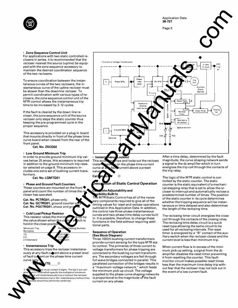
I I
*Current to Voltage Transformers
� Optional 1 I
Application Data 38-727
Page 9
TnpR�elay
. Tr1p
Co1l
'-------' Auxiliary
Power
I I I
L------ _._ ------· -- · -----
• Instantaneous Lockout This accessory trips and locks out the recloser instantaneously on the phase time current curve at any fault current above a preset value.
Cat. No. ILG CD
Description of Static Control Operation
Complete Adjustability and Flexibility Built In The MTR Static Control has all of the necessary components required to give all of the timing values for reset and reclose operations outlined in this Application Data. In addition, the control has three-phase instantaneous curves and two-phase time delay curves built in. It is possible, therefore, to change these functions in the field without requiring additional parts.
Sequence of Operation (See Block Diagram) Three 1 000/5 bushing current transformers provide current sensing for the type MTR static control. The primaries of three current to voltage transformers for phase tripping are connected to the bushing current transformers. The secondary voltages are fed through full wave bridges connected in parallel. This paralleled connection of the bridges results in a "maximum voltage network," which feeds the minimum pick-up circuit. The voltage supplied to the phase curve shaping networks is proportional to the magnitude o?the fault current on any phase.
After a time delay, determined by the fault magnitude, the curve shaping network sends a signal to the de amplifier which in turn energizes the trip coil through the contacts of the trip relay.
The logic of the MTR static control is controlled by the static counter. The static counter is the static equivalent of a mechanical stepping relay that is set to allow the recloser to interrupt and automatically reclose a predetermined number of times. The position of the static counter in its cycle determines whether the tripping sequence will be instantaneous or time delayed and also determines the length of the reclosing time.
The reclosing timer circuit energizes the close coil through the contacts of the closing relay. The reclosing time delay circuit is a quick reset type allowing the same circuit to be used for all reclosing intervals. The reset timer is energized by a "8" contact of the auxiliary switch when the recloser closes and the current level is less than minimum trip.
When current flow is in excess of the minimum pick-up setting, a signal from the de amplifier disables the reset timer preventing it from resetting the counter. This faultmonitor circuit makes possible reset times less than the maximum time delay trip without fear that the recloser may not lock out in the event of a low-current fault.
www . El
ectric
alPar
tMan
uals
. com
Page 1 0
When optional ground tripping is supplied, an additional current to voltage transformer is connected to the bushing current transformer neutral to detect circuit unbalance.
The secondary voltage of this transformer is also applied to a full wave bridge. The output voltage is applied to the DC amplifier through the ground trip minimum pickup and curve shaping network.
Time Current Curves of the ESV Recloser with Static Control Each static controlled recloser has included as standard equipment three instantaneous curves and two time delay curves for phase tripping. Units with the optional ground trip unit also include one instantaneous and one time delay curve for ground tripping. The curves must be selected from the following table.
The curves remain consistent as set with in an accuracy of plus or minus 5% throughout the temperature range of -30 degrees C to + 70 degrees C ( -22 degrees F to + 1 58 degrees F).
Table 1. Available Time Curves. CD
Description
Phase Time Curve
C0·8 (Standard) C0·9 C0·11
Ground Time Curve
C0·8 C0·9 (Standard) C0·11 C0 · 9
Style Number
201C963G01 202C040G01 202C298G01
203C221G01 203C221 G02 203C223G01 671 B592G01
CD If other curves are required contact Westinghouse.
Ordering Information The five major components of the type MTR static control listed on page 7 (excluding the accessories) have been combined into eight control packages. In addition, there are provisions for mounting and wiring the six optional accessory packages.
When ordering a static phase protection unit, the style number of the time curve must be selected and specified from Table 1 . A time curve from the same Table 1 must also be selected and specified when ordering a static ground fault unit.
When ordering any of the six accessories described on pages 8 and 9, the appropriate catalog number or numbers and/or style number must be selected and specified.
Each of the package components contain all of the features described on pages 7 and 8 under each component.
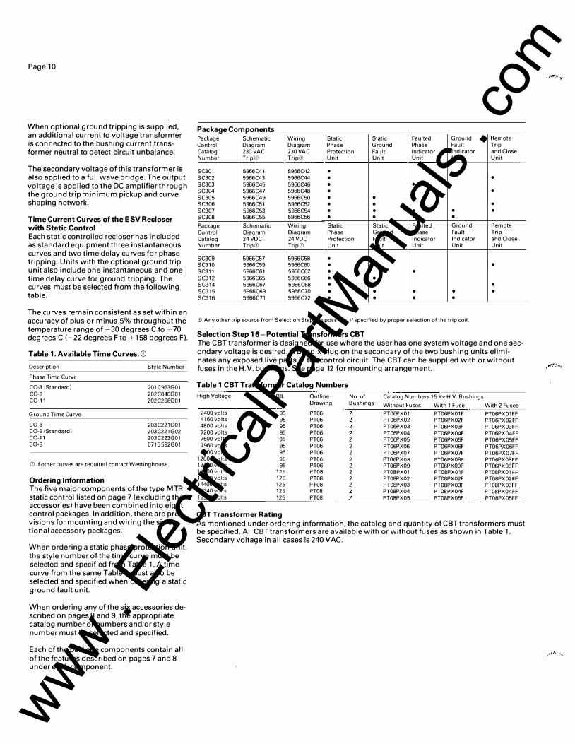
Package Components Package Schematic Wiring Static Static Faulted Ground Remote Control Diagram Diagram Phase Ground Phase Fault Trip Catalog 230 VAC 230 VAC Protection Fault Indicator Indicator and Close Number Trip CD Trip<D Unit Unit Unit Unit Unit
SC301 5966C41 5966C42 •
SC302 5966C43 5966C44 • •
SC303 5966C45 5966C46 • •
SC304 5966C47 5966C48 • • •
SC305 5966C49 5966C50 • •
SC306 5966C51 5966C52 • • . SC307 5966C53 5966C54 • • • • •
SC308 5966C55 5966C56 • • • •
Package Schematic Wiring Static Static Faulted Ground Remote Control Diagram Diagram Phase Ground Phase Fault Trip Catalog 24 VDC 24 VDC Protection Fault Indicator Indicator and Close Number Trip CD Trip CD Unit Unit Unit Unit Unit
SC309 5966C57 5966C58 • SC310 5966C59 5966C60 • •
SC311 5966C61 5966C62 • •
SC312 5966C65 5966C66 • •
SC314 5966C67 5966C68 • • •
SC315 5966C69 5966C70 • • • • •
SC316 5966C71 5966C72 • • • •
CD Any other trip source from Selection Step 4 is possible, if specified by proper selection of the trip coil.
Selection Step 16- Potential Transformers CBT The CBT transformer is designed for use where the user has one system voltage and one secondary voltage is desired. A Bendix plug on the secondary of the two bushing units eliminates any exposed live parts in the control circuit. The CBT can be supplied with or without fuses in the H.V. bushings. See page 12 for mounting arrangement.
Table 1 CBT Transformer Catalog Numbers
High Voltage BIL Outline No. of Catalog Numbers 15 Kv H.V. Bushings Drawing Bushings Without Fuses With 1 Fuse With 2 Fuses
2400 volts 95 PT06 PT06PX01 PT06PX01F PT06PX01FF 4160 volts 95 PT06 PT06PX02 PT06PX02F PT06PX02FF 4800 volts 95 PT06 PT06PX03 PT06PX03F PT06PX03FF 7200 volts 95 PT06 PT06PX04 PT06PX04F PT06PX04FF 7600 volts 95 PT06 2 PT06PX05 PT06PX05F PT06PX05FF 7960 volts 95 PT06 2 PT06PX06 PT06PX06F PT06PX06FF 8300 volts 95 PT06 2 PT06PX07 PT06PX07F PT06PX07FF
12000 volts 95 PT06 2 PT06PXOB PT06PX08F PT06PX08FF 12470 volts 95 PT06 2 PT06PX09 PT06PX09F PT06PX09FF 13200 volts 125 PT08 2 PT08PX01 PT08PX01F PT08PX01FF 13800 volts 125 PT08 2 PT08PX02 PT08PX02F PT08PX02FF 14400 volts 125 PT08 2 PT08PX03 PT08PX03F PT08PX03FF 16340 volts 125 PT08 PT08PX04 PT08PX04F PT08PX04FF 19900 volts 125 PTOS PT08PX05 PT08PX05F PT08PX05FF
CBT Transformer Rating As mentioned under ordering information, the catalog and quantity of CBT transformers must be specified. All CBT transformers are available with or without fuses as shown in Table 1 . Secondary voltage in all cases is 240 VAC.
www . El
ectric
alPar
tMan
uals
. com
Ordering Information Catalog numbers have been assigned to the connection equipment for CBT transformers. Included in the catalog number is all the necessary connectors, cable, gasket, bracket, bolts, nuts, and lock washers to mount one CBT transformer. This transformer is mounted on the left as you look into the mechanism compartment. If a second CBT transformer is required, a quantity of two must be specified and the second unit will be mounted on the right side as you look into the mechanism compartment.
Connection Equipment
Catalog No.
PETLLG01 CD
PETLGG01 CD
PETPLLG01 CD
PETPLGG01 CD
Description
CST Transformer Connection Equipment 95 or 125 BIL 2 bushing units Line to Line- 1 unit substation frame CBT Transformer Connection Equipment 95 or 125 Kv BIL 2 bushing units. Line to ground -1 unit subframe Same as PETLLG01 except for pole mounting 95 or 125 Kv BIL 2 bushing units Same as PETLGG01 except for pole mounting frame 95 or 125 Kv BIL 2 bushing units
CD Catalog number of CBT Transformer must also be speci� fied. See Table 1 this selection step for units available. If two transformers required, then quantity of two must be specified for both connection equipment and CBT transformer.
Other Optional Accessories
Ground Wire Monitoring Scheme Westinghouse has available a circuit that montitors the customer's ground circuit. The scheme trips and locks out the recloser after one operation should the customer's ground circuit open. Closing the recloser resets the circuit. The scheme can be modified to include one shot to lockout for overcu rrent relay tripping.
Bill of Material includes: Signal Transformer Auxiliary Current Transformer Ballast Resistor SC Relay GA-332 Ammeter (0-5A) Latching Relay 2-3000 ohm Resistors (if other than 24 VDC Trip) Special Capacitor Trip Device
The scheme will operate off any control power source; however, the preferred tripping source is a capacitor trip device. Select the proper control package from Step 11. The scheme is not applicable to static controlled reclosers.
See P.L. 38-720 for other optional accessories and description.
Application Data 38-727
Page 11
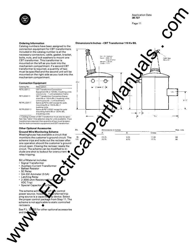
Dimensions In Inches- CBT Transformer 110 Kv BIL
25%"
BIL
95 125
�. I I \
011-2112 Gallons Pa1nt- ASA-70
Grey Enamel Welght-78 Lbs Creep-17%"
Dimensions in Inches
A
23.25 25.75
B
6.25 8.75
,�:""'"''" rr\ �to#2 I I \
f4------15W' ·-·------.,
Wgt., Lbs.
Creep
11.00 84 17.75 86
www . El
ectric
alPar
tMan
uals
. com
Application Data 38-727
Page 12
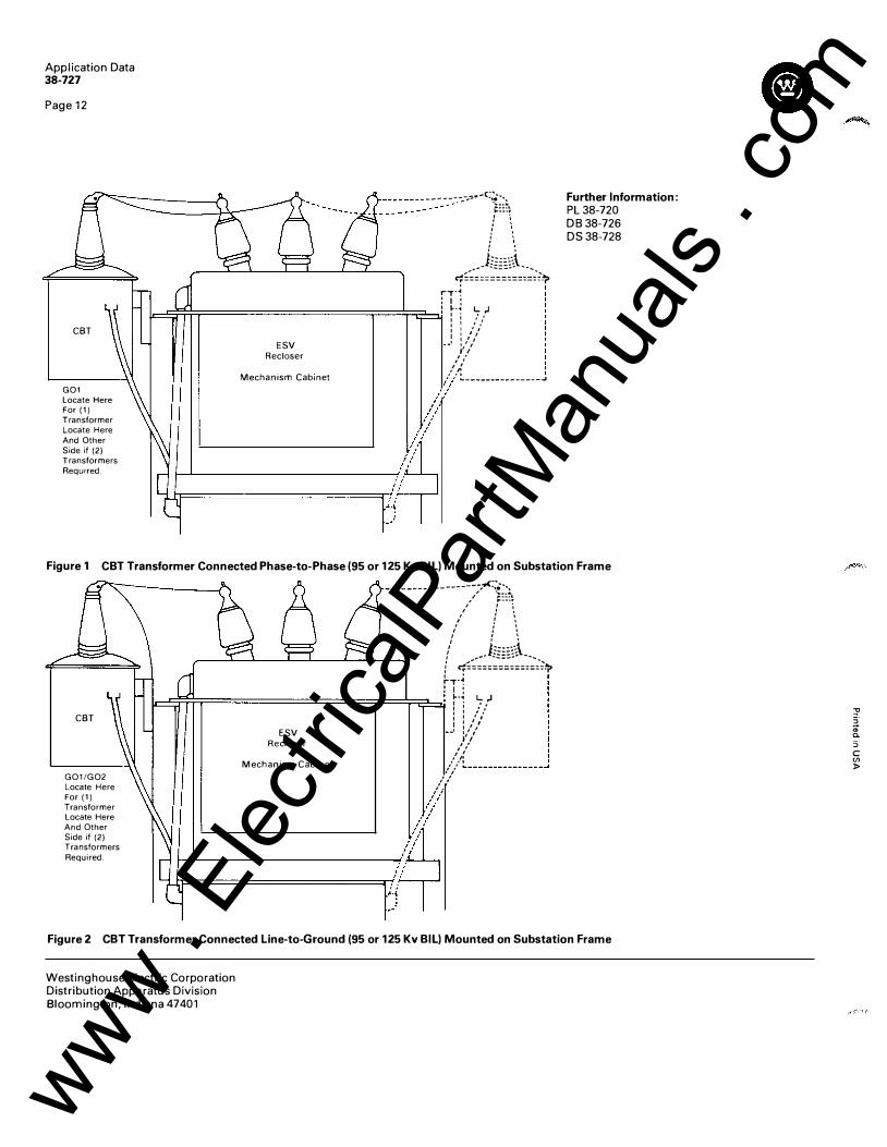
CBT
G01 Locate Here For (1) Transformer Locate Here And Other Side if (2) Transformers ReqUired.
-----------��·-'=������ I '
____ t�t __ _
�===============:')> rT-� :I : I =�;:�:::;================;==:=!:;:::2-=.J1 1-·-ot L ,.1 lJ I : i .. '
ESV Recloser
I I •/ I I ' l I : ,'/
-· ,,, 11 I ' . ' ' I I .' .': Mechanism Cabmet /.:>"' �----------------' I'
//
�/l �/I
Further Information: PL 38-720 DB 38-726 DS 38-728
Figure 1 CBT Transformer Connected Phase-to-Phase (95 or 125 Kv BILl Mounted on Substation Frame
CBT
G01/G02 Locate Here For (1) Transformer Locate Here And Other Side if (2) Transformers Required.
------------------,.<:,; .... . , ...... .. / ;::::�
/ : i, ' ' ' / t � I ' ' I ' '
I ' ' ( �s:;;�!����:��:�-;:'l> rT·� : I :
I =���::;================;==:=!n2�� �-• 1.. ,J � I ! : ,.. ... ESV
Recloser
Mechanism Cabinet
: : /�,' .. 1 I I I 11 I ' . ' ' I I / .':
/: ._ ______________ _
//,'/ I I
/ .. :::?'
;1...l;F=======/a �)�
Figure 2 CBT Transformer Connected Line-to-Ground (95 or 125 Kv BILl Mounted on Substation Frame
Westinghouse Electric Corporation Distribution Apparatus Division Bloomington, Indiana 47401
� �· "' a. :;· c en :1>
www . El
ectric
alPar
tMan
uals
. com