Embed Size (px)
Citation preview
Page 1/22
JUMO GmbH & Co. KGDelivery address: Mackenrodtstraße 14
36039 Fulda, GermanyPostal address: 36035 Fulda, GermanyPhone: +49 661 6003-0Fax: +49 661 6003-607Email: [email protected]: www.jumo.net
JUMO Instrument Co. Ltd.JUMO HouseTemple Bank, RiverwayHarlow, Essex CM20 2DY, UKPhone: +44 1279 635533Fax: +44 1279 635262Email: [email protected]: www.jumo.co.uk
JUMO Process Control, Inc.6733 Myers RoadEast Syracuse, NY 13057, USAPhone: 315-437-5866
1-800-554-5866Fax: 315-437-5860Email: [email protected]: www.jumousa.com
Data sheet 709063
V1.00/DE/00627274
Block diagram
PROFIBUS DP or RS422/485 orSystembus JUMO mTRON T
7090
63
optionally with internal r)
-in case of load current 20 A: on Slave 2-i.c.of l 32...250 A: on Master
elay( as fault alarm output or optokoupler ( as fault alarm output or energy counter)
oad current
TYA
-203
Binary inputs
Binäreingang 1frei konfigurierbar
Extra Code
2 2I, I (changeable to U, U )oder
2 2P ( I, I or U, U )changeable to
Subordinate control loop
Binary output
Power supply
Interfaces
USB interfacefor setup program
Standard signals 0(2) – 10V, 0(1) – 5V or SSR
: Setpoint, analog inputs
Firing pulse inhibitvia floating contact
Load output
Actual value output on Master- standard signals
LC-D with white backlighting
isplay
Binary input 1freely configurable
0(4) – 20mA Standard signal:
Binary input 2freely configurable
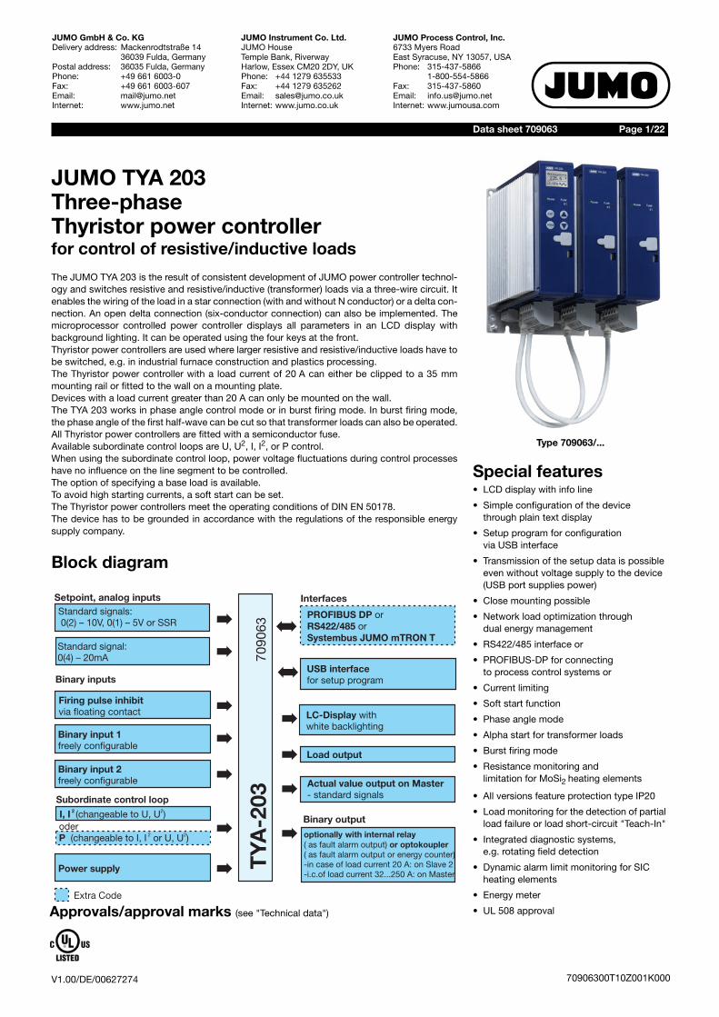
Special features• LCD display with info line
• Simple configuration of the device through plain text display
• Setup program for configuration via USB interface
• Transmission of the setup data is possible even without voltage supply to the device (USB port supplies power)
• Close mounting possible
• Network load optimization through dual energy management
• RS422/485 interface or
• PROFIBUS-DP for connecting to process control systems or
• Current limiting
• Soft start function
• Phase angle mode
• Alpha start for transformer loads
• Burst firing mode
• Resistance monitoring and limitation for MoSi2 heating elements
• All versions feature protection type IP20
• Load monitoring for the detection of partial load failure or load short-circuit "Teach-In"
• Integrated diagnostic systems,e.g. rotating field detection
• Dynamic alarm limit monitoring for SIC heating elements
• Energy meter
• UL 508 approval
JUMO TYA 203Three-phaseThyristor power controllerfor control of resistive/inductive loads
The JUMO TYA 203 is the result of consistent development of JUMO power controller technol-ogy and switches resistive and resistive/inductive (transformer) loads via a three-wire circuit. Itenables the wiring of the load in a star connection (with and without N conductor) or a delta con-nection. An open delta connection (six-conductor connection) can also be implemented. Themicroprocessor controlled power controller displays all parameters in an LCD display withbackground lighting. It can be operated using the four keys at the front.Thyristor power controllers are used where larger resistive and resistive/inductive loads have tobe switched, e.g. in industrial furnace construction and plastics processing. The Thyristor power controller with a load current of 20 A can either be clipped to a 35 mmmounting rail or fitted to the wall on a mounting plate. Devices with a load current greater than 20 A can only be mounted on the wall. The TYA 203 works in phase angle control mode or in burst firing mode. In burst firing mode,the phase angle of the first half-wave can be cut so that transformer loads can also be operated.All Thyristor power controllers are fitted with a semiconductor fuse. Available subordinate control loops are U, U2, I, I2, or P control. When using the subordinate control loop, power voltage fluctuations during control processeshave no influence on the line segment to be controlled.The option of specifying a base load is available.To avoid high starting currents, a soft start can be set.The Thyristor power controllers meet the operating conditions of DIN EN 50178.The device has to be grounded in accordance with the regulations of the responsible energysupply company.
Type 709063/...
Approvals/approval marks (see "Technical data")
70906300T10Z001K000

V1.00/DE/00627274
Data sheet 709063 Page 2/22
JUMO GmbH & Co. KGDelivery address: Mackenrodtstraße 14
36039 Fulda, GermanyPostal address: 36035 Fulda, GermanyPhone: +49 661 6003-0Fax: +49 661 6003-607Email: [email protected]: www.jumo.net
JUMO Instrument Co. Ltd.JUMO HouseTemple Bank, RiverwayHarlow, Essex CM20 2DY, UKPhone: +44 1279 635533Fax: +44 1279 635262Email: [email protected]: www.jumo.co.uk
JUMO Process Control, Inc.6733 Myers RoadEast Syracuse, NY 13057, USAPhone: 315-437-5866
1-800-554-5866Fax: 315-437-5860Email: [email protected]: www.jumousa.com
70906300T10Z001K000
Technical dataVoltage supply, load current, fan voltage only with 250 A load current
Analog inputs
Digital inputs
Digital outputs, actual value output
Code Voltage supply for control electronics = max. load voltage
Fan specificationsType 709063/X-0X-250...
024 AC 24 V -20% to +15%, 48 to 63 Hz AC 24 V / 3x30 VA
042 AC 42 V -20% to +15%, 48 to 63 Hz AC 24 V / 3x30 VA
115 AC 115 V -20% to +15%, 48 to 63 Hz AC 115 V / 3x30 VA
230 AC 230 V -20% to +15%, 48 to 63 Hz AC 230 V / 3x30 VA
265 AC 265 V -20% to +15%, 48 to 63 Hz AC 230 V / 3x30 VA
400 AC 400 V -20% to +15%, 48 to 63 Hz AC 230 V / 3x30 VA
460 AC 460 V -20% to +15%, 48 to 63 Hz AC 230 V / 3x30 VA
500 AC 500 V -20% to +15%, 48 to 63 Hz AC 230 V / 3x30 VA
Load current IL rms AC 20, 32, 50, 100, 150, 200, 250 A
Load type Resistive and resistive/inductive (transformer) loads
Power consumption of control sections max. 60 VA
Control signal 0(4) to 20 mA Ri = 50 Ω0(2) to 10 V Ri = 25 kΩ0(1) to 5 V Ri = 25 kΩ
Setpoint specification Via standard signals (current, voltage) or interface
Base load: Output as minimum actuating variable
Maximum actuating variable: Output as maximum actuating variable
Example: P control
Digital input 1, 2 For connection to potential-free contact or optocoupler, surge proof up to max. DC 32 V
Relay (changeover contact) without contact protection circuit
30000 switching operations at a switching capacity of AC 230 V / 3 A (1.5 A), 50 HzB300 (UL 508)
Optocoupler output ICmax = 2 mA, UCEOmax = 32 V
Optocoupler as energy meter Adjustment range:Number of pulses per kWh: 1...10000 Pulse length: 30 ms to 2 sec.
Actual value output Switched off as standardWith standard signal, voltage: 0 to 10 V, 2 to 10 V, 0 to 5 V, or 1 to 5 VWith standard signal, current: 0 to 20 mA or 4 to 20 mA (burden max. 500 Ω)Depending on the device type, various internal measured variables such as load current, load voltage, or power can be output
Thyristor control Setpoint specificationCurrent input(can carry current up to 25 mA)
Setpoint specificationVoltage input(surge proof up to max. DC 32 V)
Setpoint specificationDigital input1, 2(surge proof up to max. DC 32 V)
Via interface
Continuous The power controller provides the power for the load continuously de-pending on the configured setpoint specification.
- Possible
Control signal
P
Base load: 680 W
MaximumOutput level: 3680 W
0 mA 20 mA
3000W 0...20mA�
Base load

V1.00/DE/00627274
Data sheet 709063 Page 3/22
JUMO GmbH & Co. KGDelivery address: Mackenrodtstraße 14
36039 Fulda, GermanyPostal address: 36035 Fulda, GermanyPhone: +49 661 6003-0Fax: +49 661 6003-607Email: [email protected]: www.jumo.net
JUMO Instrument Co. Ltd.JUMO HouseTemple Bank, RiverwayHarlow, Essex CM20 2DY, UKPhone: +44 1279 635533Fax: +44 1279 635262Email: [email protected]: www.jumo.co.uk
JUMO Process Control, Inc.6733 Myers RoadEast Syracuse, NY 13057, USAPhone: 315-437-5866
1-800-554-5866Fax: 315-437-5860Email: [email protected]: www.jumousa.com
70906300T10Z001K000
General specifications
Weight
Logic(Solid state relay SSR)
The power controller acts like a switch and switches the load ON and OFF. The switching threshold is always in the middle of the configured current/voltage range.At 4 to 20 mA, it is 12 mA; at 0 to 10 V, it is 5 V.
OFF logical "0" = 0 to 0.8 V;ON logical "1" = 2 to 32 V
Possible
Circuit options - Delta connection (three-wire circuit)- Star connection without neutral wire (three-wire circuit)- Star connection with neutral wire (four-wire circuit)- Open delta connection (six-wire circuit)
Operating modes - Phase angle control and burst firing mode for resistive or transformer load with soft start- Alpha start for transformer loads
Load types All resistive loads up to and including transformer loads are permitted. In the case of transformer loads, the nominal induction of 1.2 tesla must not be exceeded (value is 1.45 T in the case of mains overvoltage).
Special features In the case of phase angle control operation, symmetrical current flow in all three phases
Subordinate control loop U2 configured as standard, can be freely adjusted to U, I, I2, P control depending on device type
Electrical connection For type 709063/X -0X-020...Control and load leads are connected via screw terminals
From type 709063/X -0X-032...Control cables are connected via screw terminals and load leads via cable lugs DIN 46235 and DIN 46234 or tubular cable lugs
Operating conditions The power controller is designed as a built-in device according to EN 50178, pollution degree 2, overvoltage category Ü III
Electromagnetic compatibility According to DIN 61326
Interference emission Class B
Interference immunity Industrial requirements
Protection type All device types IP20 according to EN 60529
Protection rating Protection rating I, with isolated control circuitry for connection to SELV circuits
Admissible ambient temperature range 0 to 40°C with forced air cooling using fan for type 709063/X-0X-250...
0 to 45°C with air self-cooling (expanded temperature range class 3K3 according to EN 60721-3-3)
At higher temperatures, use with reduced type current is possible (as of 45°C with type current -2%/°C)
Admissible storage temperature range -30 to +70°C (1K5 according to EN 60721-3-1)
Altitude ≤ 2000 m above MSLCaution: At site altitudes > 1000 m above MSL, the ampacity of the power controller decreases by 0.86% per 100 m
Cooling - Natural convection up to a load current of 200 A- Above 200 A of load current, forced convection with installed fan- At installation heights over 1000 m, the ampacity of the power controller decreases
Resistance to climatic conditions Relative humidity ≤ 85% annual average, no condensation 3K3 according to EN 60721
Installation position Vertical
Test voltage According to EN 50178
Creepage distances 8 mm between mains circuit and SELV circuits with type 709063/X -0X-020...,12.7 mm between mains circuit and SELV circuits with type 709063/X -0X-032...,SELV = Separate Extra Low Voltage
Housing Plastic, flammability class UL94 V0, color: cobalt blue RAL 5013
Power loss The power loss can be calculated using the following empirical formula:Pv = 3 × (20 W + 1.3 V × ILoad A)
Maximum temperature of the cooling body 110°C
A/D converter resolution 12 bit
Load current 20 A 32 A 50 A 100 A 150 A 200 A 250 A
Weight Approx. 3.3kg
Approx. 6.3kg
Approx. 8.1kg
Approx. 11.4 kg
Approx. 25.5 kg
Approx. 28.5 kg
Approx. 30.6 kg

V1.00/DE/00627274
Data sheet 709063 Page 4/22
JUMO GmbH & Co. KGDelivery address: Mackenrodtstraße 14
36039 Fulda, GermanyPostal address: 36035 Fulda, GermanyPhone: +49 661 6003-0Fax: +49 661 6003-607Email: [email protected]: www.jumo.net
JUMO Instrument Co. Ltd.JUMO HouseTemple Bank, RiverwayHarlow, Essex CM20 2DY, UKPhone: +44 1279 635533Fax: +44 1279 635262Email: [email protected]: www.jumo.co.uk
JUMO Process Control, Inc.6733 Myers RoadEast Syracuse, NY 13057, USAPhone: 315-437-5866
1-800-554-5866Fax: 315-437-5860Email: [email protected]: www.jumousa.com
70906300T10Z001K000
Approvals / approval marks
Display and measuring accuracyAll specifications refer to the controller nominal data.The values in brackets apply to the three-wire circuit as of a phase angle of ≤ 120°el.
Permissible load current depending on the ambient temperature and the site altitude
Approval mark Testing agency Certificates/certification numbers
Inspection basis Valid for type
Underwriters Laboratories 20150630-E223137 UL 508 (Category NRNT), pollution degree 2C22.2 NO. 14-10 Industrial Control Equipment (Category NRNT7)
709063/X-XX-020-...Load current 20 A
UL 508 (Category NRNT)C22.2 NO. 14-10 Industrial Control Equipment (Category NRNT7)
709063/X-XX-032...709063/X-XX-050...709063/X-XX-100...709063/X-XX-150...709063/X-XX-200...709063/X-XX-250...Load current 32 to 250 A
Mains voltage: ± 2.5% Load current: ± 1% (2%) Load voltage: ± 1% (2.5%) Power: ± 2% (4%)
Analog inputVoltage/current: ± 1%
Analog outputVoltage/current: ± 1% (2.5%)
Load resistance: ± 2% (4%)(for resistive load)
Important information:If a device temperature exceeds 105°C, the load current is gradually reduced each time the temperature increases by one degree.At a device temperature of > 115°C, the power controller cur-rent is completely switched off.
+ TYA12
11
Analog-output
45 50 60
75
20
200
T/°C
150
Load current in A
Reduction at a temperature of 45 °C:
2 %/kelvin70 %250
100
50

V1.00/DE/00627274
Data sheet 709063 Page 5/22
JUMO GmbH & Co. KGDelivery address: Mackenrodtstraße 14
36039 Fulda, GermanyPostal address: 36035 Fulda, GermanyPhone: +49 661 6003-0Fax: +49 661 6003-607Email: [email protected]: www.jumo.net
JUMO Instrument Co. Ltd.JUMO HouseTemple Bank, RiverwayHarlow, Essex CM20 2DY, UKPhone: +44 1279 635533Fax: +44 1279 635262Email: [email protected]: www.jumo.co.uk
JUMO Process Control, Inc.6733 Myers RoadEast Syracuse, NY 13057, USAPhone: 315-437-5866
1-800-554-5866Fax: 315-437-5860Email: [email protected]: www.jumousa.com
70906300T10Z001K000
Galvanic isolation
Important information:The altitude is ≤ 2000 m above MSL.In the case of air cooling, it must be noted that the effectiveness of the cooling is reduced the higher up the site altitude at which the device is installed. As a result, the ampacity of the Thyristor controller decreases with the stated cooler as the site altitude increases, as shown here in the diagram.
1000 2000
40
20
100
site altitude in mabove sea level
80
Ampacity in %
91,4%
60
3000 4000 5000
Reduction over 1000m above sea level: 0,86 %/100m
AC 3800 V
AC 3800 V
AC 350 V AC 350 V
PROFIBUS-DP or RS422/485 serial interface orSystembus mTRON T
Actual value outputstandard signal Voltage outputDC 10 V
Binary output Relay or optocoupler
Load connection U1, U2
Display and keypad
Binary floating contact
input 1, 2
USB Interface
Analog input0(4) to 20 mA
Analog input0(2) to 10 V, 0 to 5 Vor SSR
Voltage supply
���
��

V1.00/DE/00627274
Data sheet 709063 Page 6/22
JUMO GmbH & Co. KGDelivery address: Mackenrodtstraße 14
36039 Fulda, GermanyPostal address: 36035 Fulda, GermanyPhone: +49 661 6003-0Fax: +49 661 6003-607Email: [email protected]: www.jumo.net
JUMO Instrument Co. Ltd.JUMO HouseTemple Bank, RiverwayHarlow, Essex CM20 2DY, UKPhone: +44 1279 635533Fax: +44 1279 635262Email: [email protected]: www.jumo.co.uk
JUMO Process Control, Inc.6733 Myers RoadEast Syracuse, NY 13057, USAPhone: 315-437-5866
1-800-554-5866Fax: 315-437-5860Email: [email protected]: www.jumousa.com
70906300T10Z001K000
Display, operating, and connection elements
DimensionsType 709063/X-0X-20A-XXX-XXX-XX-25X
Legend Comment Diagram
1 The Power LED (green) is permanently lit when the voltage supply is con-nected.
2 LCD display with white backlight (96 x 64 pixels)(no LCD display on slave devices on the right).The information line at the bottom of the display shows the current set-tings and error messages.
3 Fuse LED (red) is lit in the event of a defective semiconductor fuse.
4 LED K1 (yellow) fault signal output
5 Keys:
Value increase / previous parameter
Value reduction / next parameter
Cancel / back one level
Programming / one level deeper
(no keys on slave devices on the right)
6 USB setup interfaceThe configuration is made on the left device (master) and automatically transferred to both slaves via a 1:1 patch cable.
7 Spring clip to release the plastic housing (press toward right)

V1.00/DE/00627274
Data sheet 709063 Page 7/22
JUMO GmbH & Co. KGDelivery address: Mackenrodtstraße 14
36039 Fulda, GermanyPostal address: 36035 Fulda, GermanyPhone: +49 661 6003-0Fax: +49 661 6003-607Email: [email protected]: www.jumo.net
JUMO Instrument Co. Ltd.JUMO HouseTemple Bank, RiverwayHarlow, Essex CM20 2DY, UKPhone: +44 1279 635533Fax: +44 1279 635262Email: [email protected]: www.jumo.co.uk
JUMO Process Control, Inc.6733 Myers RoadEast Syracuse, NY 13057, USAPhone: 315-437-5866
1-800-554-5866Fax: 315-437-5860Email: [email protected]: www.jumousa.com
70906300T10Z001K000
Type 709063/X-0X-032-XXX-XXX-XX-25X
Type 709063/X-0X-050-XXX-XXX-XX-25X

V1.00/DE/00627274
Data sheet 709063 Page 8/22
JUMO GmbH & Co. KGDelivery address: Mackenrodtstraße 14
36039 Fulda, GermanyPostal address: 36035 Fulda, GermanyPhone: +49 661 6003-0Fax: +49 661 6003-607Email: [email protected]: www.jumo.net
JUMO Instrument Co. Ltd.JUMO HouseTemple Bank, RiverwayHarlow, Essex CM20 2DY, UKPhone: +44 1279 635533Fax: +44 1279 635262Email: [email protected]: www.jumo.co.uk
JUMO Process Control, Inc.6733 Myers RoadEast Syracuse, NY 13057, USAPhone: 315-437-5866
1-800-554-5866Fax: 315-437-5860Email: [email protected]: www.jumousa.com
70906300T10Z001K000
Type 709063/X-0X-100-XXX-XXX-XX-25X

V1.00/DE/00627274
Data sheet 709063 Page 9/22
JUMO GmbH & Co. KGDelivery address: Mackenrodtstraße 14
36039 Fulda, GermanyPostal address: 36035 Fulda, GermanyPhone: +49 661 6003-0Fax: +49 661 6003-607Email: [email protected]: www.jumo.net
JUMO Instrument Co. Ltd.JUMO HouseTemple Bank, RiverwayHarlow, Essex CM20 2DY, UKPhone: +44 1279 635533Fax: +44 1279 635262Email: [email protected]: www.jumo.co.uk
JUMO Process Control, Inc.6733 Myers RoadEast Syracuse, NY 13057, USAPhone: 315-437-5866
1-800-554-5866Fax: 315-437-5860Email: [email protected]: www.jumousa.com
70906300T10Z001K000
Type 709063/X-0X-150-XXX-XXX-XX-25XType 709063/X-0X-200-XXX-XXX-XX-25X
Clearances (all types)• Allow a clearance of 10 cm from the floor
• Allow a clearance of 15 cm from the ceiling
• When devices are fitted in close mounting, no spacing is required
V1.00/DE/00627274
Data sheet 709063 Page 10/22
JUMO GmbH & Co. KGDelivery address: Mackenrodtstraße 14
36039 Fulda, GermanyPostal address: 36035 Fulda, GermanyPhone: +49 661 6003-0Fax: +49 661 6003-607Email: [email protected]: www.jumo.net
JUMO Instrument Co. Ltd.JUMO HouseTemple Bank, RiverwayHarlow, Essex CM20 2DY, UKPhone: +44 1279 635533Fax: +44 1279 635262Email: [email protected]: www.jumo.co.uk
JUMO Process Control, Inc.6733 Myers RoadEast Syracuse, NY 13057, USAPhone: 315-437-5866
1-800-554-5866Fax: 315-437-5860Email: [email protected]: www.jumousa.com
70906300T10Z001K000
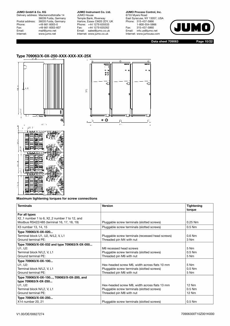
Type 709063/X-0X-250-XXX-XXX-XX-25X
Maximum tightening torques for screw connections
Terminals Version Tightening torque
For all typesX2_1 number 1 to 6, X2_2 number 7 to 12, andModbus RS422/485 (terminal 16, 17, 18, 19) Pluggable screw terminals (slotted screws) 0.25 Nm
X3 number 13, 14, 15 Pluggable screw terminals (slotted screws) 0.5 Nm
Type 709063/X-0X-020...Terminal block U1, U2, N/L2, V, L1 Ground terminal PE:
Pluggable screw terminals (recessed head screws)Threaded pin M4 with nut
0.6 Nm3 Nm
Type 709063/X-0X-032 and type 709063/X-0X-050...U1, U2: Terminal block N/L2, V, L1 Ground terminal PE:
M6 recessed head screwsPluggable screw terminals (slotted screws)Threaded pin M6 with nut
5 Nm0.5 Nm5 Nm
Type 709063/X-0X-100...U1, U2: Terminal block N/L2, V, L1 Ground terminal PE:
Hex-headed screw M6, width across flats 10 mmPluggable screw terminals (slotted screws)Threaded pin M6 with nut
5 Nm0.5 Nm5 Nm
Type 709063/X-0X-150..., 709063/X-0X-200, and type 709063/X-0X-250...U1, U2:Terminal block N/L2, V, L1Ground terminal PE:
Hex-headed screw M8, width across flats 13 mmPluggable screw terminals (slotted screws)Threaded pin M8 with nut
12 Nm0.5 Nm12 Nm
Type 709063/X-0X-250...X14 number 20, 21 Pluggable screw terminals (slotted screws) 0.5 Nm

V1.00/DE/00627274
Data sheet 709063 Page 11/22
JUMO GmbH & Co. KGDelivery address: Mackenrodtstraße 14
36039 Fulda, GermanyPostal address: 36035 Fulda, GermanyPhone: +49 661 6003-0Fax: +49 661 6003-607Email: [email protected]: www.jumo.net
JUMO Instrument Co. Ltd.JUMO HouseTemple Bank, RiverwayHarlow, Essex CM20 2DY, UKPhone: +44 1279 635533Fax: +44 1279 635262Email: [email protected]: www.jumo.co.uk
JUMO Process Control, Inc.6733 Myers RoadEast Syracuse, NY 13057, USAPhone: 315-437-5866
1-800-554-5866Fax: 315-437-5860Email: [email protected]: www.jumousa.com
70906300T10Z001K000
Connection diagramThe connection diagram in the data sheet provides preliminary information about the connection options. For the electrical connection only usethe installation instructions or the operating manual. The knowledge and the correct technical execution of the safety information and warningscontained in these documents are mandatory for mounting, electrical connection, startup, and for safety during operation.
Type 709063/X-0X-20-XXX-XXX-XX-25X
Control section
Power sectionConnection for Screw terminals, control section/power
sectionDetail
Voltage supply for control electronics(corresponds to maximum load voltageof ordered device type)
L1N/L2V
Load connection U1U2
Protection conductor PE
Fan X14 20, 21 (only for load current of 250 A)
Connection for Screw terminal X2_1 Detail
Setpoint specification for current input 12
(N/L2)
(V)
(L1)
Vo
lta
ge
su
pp
lyC
on
tro
l e
lectr
on
ics
( 2)X2_
(X2_1)
(X8_1)
( )X3
(PE)
Master Slave1
Contr
ol
section
kein
eF
unktion
(U1)
(U2)
Slave2
Po
we
r se
ctio
n
(X8_2)
Important information:Master/slave connections are already plugged per default. The device is already configured such that only the voltage supply and the load need to be configured.
L1
Measuring load voltageControl-electronic
Phase (L1, L2, L3)
Phase (L1, L2, L3) oder N cond. (N)V
N/L2TYA
U2
U1
Load
Phase (L1, L2, L3)
PE PE TYA
20
21
Voltage supply for fan
+–
Ix Current-input
TYA
2
1

V1.00/DE/00627274
Data sheet 709063 Page 12/22
JUMO GmbH & Co. KGDelivery address: Mackenrodtstraße 14
36039 Fulda, GermanyPostal address: 36035 Fulda, GermanyPhone: +49 661 6003-0Fax: +49 661 6003-607Email: [email protected]: www.jumo.net
JUMO Instrument Co. Ltd.JUMO HouseTemple Bank, RiverwayHarlow, Essex CM20 2DY, UKPhone: +44 1279 635533Fax: +44 1279 635262Email: [email protected]: www.jumo.co.uk
JUMO Process Control, Inc.6733 Myers RoadEast Syracuse, NY 13057, USAPhone: 315-437-5866
1-800-554-5866Fax: 315-437-5860Email: [email protected]: www.jumousa.com
70906300T10Z001K000
Master-slave connection
Fault signal output
Interfaces (option)
Setpoint specification for voltage input(surge proof up to max. DC 32 V)
3 (GND)4
Output DC 10 V fixed voltage 5
Ground potential 6 (GND)
Connection for Screw terminal X2_2 Detail
Firing pulse inhibit
ON logical "1" = DC 2 to 32 VOFF logical "0" = DC 0 to 0.8 V
8
Digital input1
ON logical "1" = DC 2 to 32 VOFF logical "0" = DC 0 to 0.8 V
9
Digital input2
ON logical "1" = DC 2 to 32 VOFF logical "0" = DC 0 to 0.8 V
10
GND 7, 11 Ground potential
Analog outputfor various internal controller variables
12
Connection for RJ 45 socket X8_1 and X8_2
Master-Slave1 and Master-Slave2 Both 1:1 patch cables (included in scope of delivery) must be plugged for correct operation (X8_1 connection to Slave1, X8_2 connection to Slave2).If the patch cables are mixed up on the master, the device reports a rotary field error.
Connection for Screw terminal X3 Detail
Relay or optocoupleris on Slave2 at load current of 20 Aand on Master at 32...250 A
13 N/O contact or collector
14 N/C contact
15 pole or emitter
Modbus connection RS422 RS485 JUMO mTRON T system bus Connection PROFIBUS-DP
Pluggable screw ter-minals on the under-side of the housing
TxD (-) RxD/TxD B(-) 1 TX+ Transmission da-ta+
SUB-D socket 9-pin(on the front)
3 A(+)
TxD (+) RxD/TxD A(+) 2 TX- Transmission data -
8 B(-)
RxD (-) - 3 RX+ Received data + 6 VCC
RxD (+) - 6 RX Received data - 5 GND
Shield-ing
E
S
A
5k�
TYA
DC +10 V
4
3
+
–
Ux
3
5
4
external Setpointspecification with potentiometer
Voltageinput
11
10
3,3V
10k�
TYA
8
7
+
–
U
88
77
11
10
3,3V
10k�
TYA
9
11
+
–
U 11
9
11
9
11
10
3,3V
10k�
TYA
10
11
+
–
U 11
10
11
10
+ TYA12
11
Analog-output
E
S
C
ÖP
1314
15
Relay- oroptocouplerOutput
TYA
1617
1918
81
67
89
23
45
1

V1.00/DE/00627274
Data sheet 709063 Page 13/22
JUMO GmbH & Co. KGDelivery address: Mackenrodtstraße 14
36039 Fulda, GermanyPostal address: 36035 Fulda, GermanyPhone: +49 661 6003-0Fax: +49 661 6003-607Email: [email protected]: www.jumo.net
JUMO Instrument Co. Ltd.JUMO HouseTemple Bank, RiverwayHarlow, Essex CM20 2DY, UKPhone: +44 1279 635533Fax: +44 1279 635262Email: [email protected]: www.jumo.co.uk
JUMO Process Control, Inc.6733 Myers RoadEast Syracuse, NY 13057, USAPhone: 315-437-5866
1-800-554-5866Fax: 315-437-5860Email: [email protected]: www.jumousa.com
70906300T10Z001K000
Type 709063/X-0X-032-XXX-XXX-XX-25X
The shield of the Modbus cables must be routed on ground potential (PE)
2 RJ-45 sockets (on the front)16
1719
18
(RS422/485 )Modbus
PROFIBUS-DP
kein
eF
unktion
kein
eF
unktion
( 2)X2_
(X2_1)
(X8_1)
( )X3
(U1)
(U2)
(N/L2)
(V)
(L1)
(PE)
kein
eF
unktion
kein
eF
unktion
Master Slave1 Slave2
(X8_2)

V1.00/DE/00627274
Data sheet 709063 Page 14/22
JUMO GmbH & Co. KGDelivery address: Mackenrodtstraße 14
36039 Fulda, GermanyPostal address: 36035 Fulda, GermanyPhone: +49 661 6003-0Fax: +49 661 6003-607Email: [email protected]: www.jumo.net
JUMO Instrument Co. Ltd.JUMO HouseTemple Bank, RiverwayHarlow, Essex CM20 2DY, UKPhone: +44 1279 635533Fax: +44 1279 635262Email: [email protected]: www.jumo.co.uk
JUMO Process Control, Inc.6733 Myers RoadEast Syracuse, NY 13057, USAPhone: 315-437-5866
1-800-554-5866Fax: 315-437-5860Email: [email protected]: www.jumousa.com
70906300T10Z001K000
Type 709063/X-0X-050-XXX-XXX-XX-25X
Type 709063/X-0X-100-XXX-XXX-XX-25X
kein
eF
unktion
kein
eF
unktion
kein
eF
unktion
kein
eF
unktion
( 2)X2_
(X2_1)
(X8_1)
( )X3
(U1)
(U2)
(PE)
Master Slave1 Slave2
(N/L2)
(V)
(L1)
(X8_2)ke
ine
Fu
nktio
nkein
eF
unktion
Master Slave1 Slave2
( 2)X2_
(X2_1)
( )X3
(U1)
(U2)
(N/L2)
(V)
(L1)
(PE)
ke
ine
Fu
nktio
nkein
eF
unktion
(X8_1)
(X8_2)

V1.00/DE/00627274
Data sheet 709063 Page 15/22
JUMO GmbH & Co. KGDelivery address: Mackenrodtstraße 14
36039 Fulda, GermanyPostal address: 36035 Fulda, GermanyPhone: +49 661 6003-0Fax: +49 661 6003-607Email: [email protected]: www.jumo.net
JUMO Instrument Co. Ltd.JUMO HouseTemple Bank, RiverwayHarlow, Essex CM20 2DY, UKPhone: +44 1279 635533Fax: +44 1279 635262Email: [email protected]: www.jumo.co.uk
JUMO Process Control, Inc.6733 Myers RoadEast Syracuse, NY 13057, USAPhone: 315-437-5866
1-800-554-5866Fax: 315-437-5860Email: [email protected]: www.jumousa.com
70906300T10Z001K000
Type 709063/X-0X-150-XXX-XXX-XX-25X,Type 709063/X-0X-200-XXX-XXX-XX-25X
kein
eF
unktion
kein
eF
unktion
Master Slave1 Slave2
( 2)X2_
(X2_1)
(X8_1)
( )X3
(U1)
(U2)
(N/L2)(V)
(L1)
(PE)
kein
eF
unktion
kein
eF
unktion
(U1) (U1)(U2) (U2)
(X8_2)
V1.00/DE/00627274
Data sheet 709063 Page 16/22
JUMO GmbH & Co. KGDelivery address: Mackenrodtstraße 14
36039 Fulda, GermanyPostal address: 36035 Fulda, GermanyPhone: +49 661 6003-0Fax: +49 661 6003-607Email: [email protected]: www.jumo.net
JUMO Instrument Co. Ltd.JUMO HouseTemple Bank, RiverwayHarlow, Essex CM20 2DY, UKPhone: +44 1279 635533Fax: +44 1279 635262Email: [email protected]: www.jumo.co.uk
JUMO Process Control, Inc.6733 Myers RoadEast Syracuse, NY 13057, USAPhone: 315-437-5866
1-800-554-5866Fax: 315-437-5860Email: [email protected]: www.jumousa.com
70906300T10Z001K000
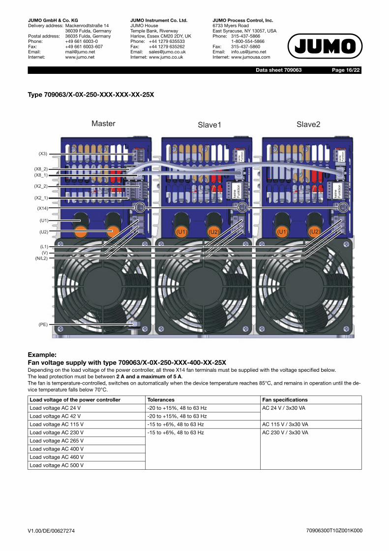
Type 709063/X-0X-250-XXX-XXX-XX-25X
Example: Fan voltage supply with type 709063/X-0X-250-XXX-400-XX-25XDepending on the load voltage of the power controller, all three X14 fan terminals must be supplied with the voltage specified below.The lead protection must be between 2 A and a maximum of 5 A.The fan is temperature-controlled, switches on automatically when the device temperature reaches 85°C, and remains in operation until the de-vice temperature falls below 70°C.
Load voltage of the power controller Tolerances Fan specifications
Load voltage AC 24 V -20 to +15%, 48 to 63 Hz AC 24 V / 3x30 VA
Load voltage AC 42 V -20 to +15%, 48 to 63 Hz
Load voltage AC 115 V -15 to +6%, 48 to 63 Hz AC 115 V / 3x30 VA
Load voltage AC 230 V -15 to +6%, 48 to 63 Hz AC 230 V / 3x30 VA
Load voltage AC 265 V
Load voltage AC 400 V
Load voltage AC 460 V
Load voltage AC 500 V
(U2) (U2)(U1) (U1)
kein
eF
unktion
ke
ine
Fu
nktio
n
( 2)X2_
(X2_1)
(X8_1)
( )X3
(U1)
(U2)
(N/L2)
(V)
(L1)
(PE)
kein
eF
unktion
ke
ine
Fu
nktio
n
(X14)
Master Slave1 Slave2
(X8_2)

V1.00/DE/00627274
Data sheet 709063 Page 17/22
JUMO GmbH & Co. KGDelivery address: Mackenrodtstraße 14
36039 Fulda, GermanyPostal address: 36035 Fulda, GermanyPhone: +49 661 6003-0Fax: +49 661 6003-607Email: [email protected]: www.jumo.net
JUMO Instrument Co. Ltd.JUMO HouseTemple Bank, RiverwayHarlow, Essex CM20 2DY, UKPhone: +44 1279 635533Fax: +44 1279 635262Email: [email protected]: www.jumo.co.uk
JUMO Process Control, Inc.6733 Myers RoadEast Syracuse, NY 13057, USAPhone: 315-437-5866
1-800-554-5866Fax: 315-437-5860Email: [email protected]: www.jumousa.com
70906300T10Z001K000
WiringDelta connection (three-wire circuit)Star connection without neutral wire (three-wire circuit)Star connection with neutral wire (four-wire circuit)
Important in-formation:
In the case of power controllers with a load current of 250 A, both X14 fan terminals of the Master, Slave1, and Slave2 must also be supplied with the stated voltage, see "Example: Fan voltage supply with type 709063/X-0X-250-XXX-400-XX-25X". page 16
*N depends on the application with N-Conductor (4-Conductor wiring)
*N
wit
h N
-Co
nduc
tor
(4-C
ond
ucto
r w
irin
g)
dep
end
s o
n th
e ap
plic
atio
n
Master Slave 1 Slave 2
TYA 203 load current 20A
Master (L1) Slave1 (L2) Slave2 (L3)
Note the correct sequence!
Attention:Make sure that the roating electrical fieldof L1, L2 and L3 is right-handed!
Ohmic load in a delta connection
Ohmic load in a star connection
Setpoint input:
Fus
ing
to p
rote
ct t
he
pow
er s
ectio
n ca
blin
g
Fuse for control electronics 2A up toa maximum of 5A
0(4)...20mA -+
IThy
L1 NL2 L3 PE
UL UN
IL
E
OptokopplerC
U = phase-phase voltageL
U = phase-neutral voltageN
U = voltage on thyristor power unitThy
P = total controlled powertot
I = current in phase conductorL
I = current in thyristor power unitThy
1211
108
97
65
42
31
81
81
N/L2 L1V U1U2
U = UThy L
I = Thy
Ptot
3 · UN
=Ptot
3 UL·
I = Thy IL
1314
1512
1110
89
7
65
42
31
81
N/L2 L1V U1U213
1415
1211
108
97
65
42
31
81
N/L2 L1V U1U2
Sconductor-fuse
emi-
S
ÖP
E
Ccable
RelayOptocoupler
Sconductor-fuse
emi- Sconductor-fuse
emi-

V1.00/DE/00627274
Data sheet 709063 Page 18/22
JUMO GmbH & Co. KGDelivery address: Mackenrodtstraße 14
36039 Fulda, GermanyPostal address: 36035 Fulda, GermanyPhone: +49 661 6003-0Fax: +49 661 6003-607Email: [email protected]: www.jumo.net
JUMO Instrument Co. Ltd.JUMO HouseTemple Bank, RiverwayHarlow, Essex CM20 2DY, UKPhone: +44 1279 635533Fax: +44 1279 635262Email: [email protected]: www.jumo.co.uk
JUMO Process Control, Inc.6733 Myers RoadEast Syracuse, NY 13057, USAPhone: 315-437-5866
1-800-554-5866Fax: 315-437-5860Email: [email protected]: www.jumousa.com
70906300T10Z001K000
Delta connection (three-wire circuit)Star connection without neutral wire (three-wire circuit)Star connection with neutral wire (four-wire circuit)
Important in-formation:
In the case of power controllers with a load current of 250 A, both X14 fan terminals of the Master, Slave1, and Slave2 must also be supplied with the stated voltage, see "Example: Fan voltage supply with type 709063/X-0X-250-XXX-400-XX-25X". page 16
Master (L1) Slave1 (L2) Slave2 (L3)
Note the correct sequence!
Attention:Make sure that the roating electrical fieldof L1, L2 and L3 is right-handed!
Ohmic load in a delta connection
Ohmic load in a star connection
Setpoint input:
*N
wit
h N
-Co
nduc
tor
(4-C
ond
ucto
r w
irin
g)
dep
end
s o
n th
e ap
plic
atio
n
*N depends on the application with N-Conductor (4-Conductor wiring)
Fus
ing
to p
rote
ct t
he
pow
er s
ectio
n ca
blin
gFuse for control electronics 2A up toa maximum of 5A
0(4)...20mA -+
TYA 203 load current 32 A ... 250 A
IThy
L1 NL2 L3 PE
UL UN
IL
U = phase-phase voltageL
U = phase-neutral voltageN
U = voltage on thyristor power unitThy
P = total controlled powertot
I = current in phase conductorL
I = current in thyristor power unitThy
U1U2N/L2 L1V
1211
108
97
65
42
31
81
81
1314
15
S
ÖP
E
C
Fanonly fortype250 A
U1U2N/L2 L1V
1314
1512
1110
89
7
65
42
31
81
1:1 Patchkabel
U1U2N/L2 L1V
1211
108
97
65
42
31
81
1314
15
U = UThy L
I = Thy
Ptot
3 · UN
=Ptot
3 UL·
I = Thy IL
Master Slave 1 Slave 2
Sconductor-fuse
emi-Sconductor-fuse
emi- Sconductor-fuse
emi-
RelayOptocoupler
Fanonly fortype250 A
Fanonly fortype250 A
cable

V1.00/DE/00627274
Data sheet 709063 Page 19/22
JUMO GmbH & Co. KGDelivery address: Mackenrodtstraße 14
36039 Fulda, GermanyPostal address: 36035 Fulda, GermanyPhone: +49 661 6003-0Fax: +49 661 6003-607Email: [email protected]: www.jumo.net
JUMO Instrument Co. Ltd.JUMO HouseTemple Bank, RiverwayHarlow, Essex CM20 2DY, UKPhone: +44 1279 635533Fax: +44 1279 635262Email: [email protected]: www.jumo.co.uk
JUMO Process Control, Inc.6733 Myers RoadEast Syracuse, NY 13057, USAPhone: 315-437-5866
1-800-554-5866Fax: 315-437-5860Email: [email protected]: www.jumousa.com
70906300T10Z001K000
Open delta connection (six-wire connection)
Important in-formation:
In the case of power controllers with a load current of 250 A, both X14 fan terminals of the Master, Slave1, and Slave2 must also be supplied with the stated voltage, see "Example: Fan voltage supply with type 709063/X-0X-250-XXX-400-XX-25X". page 16
load
IThy
L1 NL2 L3 PE
UL UN
IL
U = phase-phase voltageL
U = phase-neutral voltageN
U = voltage on thyristor power unitThy
P = total controlled powertot
I = current in phase conductorL
I = current in thyristor power unitThy
Fus
ing
to p
rote
ct t
he
pow
er s
ectio
n ca
blin
g
3
U = UThy L
I = Thy
Ptot
3 · UL
=Ptot
3 3 UN · ·
ILI =thy
0(4)...20mA -+
Master
E
OptokopplerC
1211
108
97
65
42
31
81
81
N/L2 L1V U1U2
TYA 203 load current 20A
Slave 1
1314
1512
1110
89
7
65
42
31
81
N/L2 L1V U1U2
1:1 Patchkabel
Slave 2
1314
1512
1110
89
7
65
42
31
81
N/L2 L1V U1U2
S
ÖP
E
C
Fuse for control electronics 2A up toa maximum of 5A
Setpoint input:
Sconductor-fuse
emi- Sconductor-fuse
emi- Sconductor-fuse
emi-
RelayOptocoupler
Master (L1) Slave1 (L2) Slave2 (L3)
Note the correct sequence!
Attention:Make sure that the roating electrical fieldof L1, L2 and L3 is right-handed!
cable

V1.00/DE/00627274
Data sheet 709063 Page 20/22
JUMO GmbH & Co. KGDelivery address: Mackenrodtstraße 14
36039 Fulda, GermanyPostal address: 36035 Fulda, GermanyPhone: +49 661 6003-0Fax: +49 661 6003-607Email: [email protected]: www.jumo.net
JUMO Instrument Co. Ltd.JUMO HouseTemple Bank, RiverwayHarlow, Essex CM20 2DY, UKPhone: +44 1279 635533Fax: +44 1279 635262Email: [email protected]: www.jumo.co.uk
JUMO Process Control, Inc.6733 Myers RoadEast Syracuse, NY 13057, USAPhone: 315-437-5866
1-800-554-5866Fax: 315-437-5860Email: [email protected]: www.jumousa.com
70906300T10Z001K000
Open delta connection (six-wire connection)
Important in-formation:
In the case of power controllers with a load current of 250 A, both X14 fan terminals of the Master, Slave1, and Slave2 must also be supplied with the stated voltage, see "Example: Fan voltage supply with type 709063/X-0X-250-XXX-400-XX-25X". page 16
load
TYA 203 Laststrom 32 A ... 250 A
IThy
L1 NL2 L3 PE
UL UN
IL
U = phase-phase voltageL
U = phase-neutral voltageN
U = voltage on thyristor power unitThy
P = total controlled powertot
I = current in phase conductorL
I = current in thyristor power unitThy
U1U2N/L2 L1V
1211
108
97
65
42
31
81
81
1314
15
S
ÖP
E
C
Master
U1U2N/L2 L1V
1314
1512
1110
89
7
65
42
31
81
1:1 Patchkabel
Slave 1
U1U2N/L2 L1V
1211
108
97
65
42
31
81
1314
15
Slave 2
RelayOptocoupler
Fanonly fortype250 A
Fanonly fortype250 A
Fanonly fortype250 A
Fuse for control electronics 2A up toa maximum of 5A
Fus
ing
to p
rote
ct t
he
pow
er s
ectio
n ca
blin
g
Setpoint input:
Master (L1) Slave1 (L2) Slave2 (L3)
Note the correct sequence!
Attention:Make sure that the roating electrical fieldof L1, L2 and L3 is right-handed!
3
U = UThy L
I = Thy
Ptot
3 · UL
=Ptot
3 3 UN · ·
ILI =thy
0(4)...20mA -+
cable
Sconductor-fuse
emi- Sconductor-fuse
emi- Sconductor-fuse
emi-

V1.00/DE/00627274
Data sheet 709063 Page 21/22
JUMO GmbH & Co. KGDelivery address: Mackenrodtstraße 14
36039 Fulda, GermanyPostal address: 36035 Fulda, GermanyPhone: +49 661 6003-0Fax: +49 661 6003-607Email: [email protected]: www.jumo.net
JUMO Instrument Co. Ltd.JUMO HouseTemple Bank, RiverwayHarlow, Essex CM20 2DY, UKPhone: +44 1279 635533Fax: +44 1279 635262Email: [email protected]: www.jumo.co.uk
JUMO Process Control, Inc.6733 Myers RoadEast Syracuse, NY 13057, USAPhone: 315-437-5866
1-800-554-5866Fax: 315-437-5860Email: [email protected]: www.jumousa.com
70906300T10Z001K000
Order details(1) Basic type
709063 TYA 203 three-phase Thyristor power controller
(2) Version
8 Standard with default settings
9 Customer-specific programming according to specifications
(3) National language of display texts
01 German (default setting)
02 English
03 French
14 Spanish
(4) Load current
020 AC 20 A
032 AC 32 A
050 AC 50 A
100 AC 100 A
150 AC 150 A
200 AC 200 A
250 AC 250 A
(5) Subordinate control loop (see important Information below)
010 I, I2 (can be set to U, U2)
001 P (can be set to I, I2 or U, U2)
(6) Load voltagea
a Load voltage = voltage supply for control electronics
024 AC 24 V -20 to +15%, 48 to 63 Hz
042 AC 42 V -20 to +15%, 48 to 63 Hz
115 AC 115 V -20 to +15%, 48 to 63 Hz
230 AC 230 V -20 to +15%, 48 to 63 Hz
265 AC 265 V -20 to +15%, 48 to 63 Hz
400 AC 400 V -20 to +15%, 48 to 63 Hz
460 AC 460 V -20 to +15%, 48 to 63 Hz
500 AC 500 V -20 to +15%, 48 to 63 Hz
(7) Interface
00 None
54 RS485/422
64 PROFIBUS-DP
84 JUMO mTRON T system interface
(8) Extra codes
252 Relay (changeover contact) 3 A
257 Optocouplerb
b Enables energy meter
(1) (2) (3) (4) (5) (6) (7) (8)
/ - - - - - / Order code
709063 / 8 - 01 - 100 - 100 - 400 - 00 / 252 Order example
Importantinformation:
Subordinate control loop I2, code 010: enables voltage control, current control, partial load failure detection, dual energy man-agement, current limiting and energy meterSubordinate control loop P, code 001: enables voltage control, current control, power control, partial load failure detection, dualenergy management, current limiting, r-control and and energy meterNote fan voltage at 250 A load current!

V1.00/DE/00627274
Data sheet 709063 Page 22/22
JUMO GmbH & Co. KGDelivery address: Mackenrodtstraße 14
36039 Fulda, GermanyPostal address: 36035 Fulda, GermanyPhone: +49 661 6003-0Fax: +49 661 6003-607Email: [email protected]: www.jumo.net
JUMO Instrument Co. Ltd.JUMO HouseTemple Bank, RiverwayHarlow, Essex CM20 2DY, UKPhone: +44 1279 635533Fax: +44 1279 635262Email: [email protected]: www.jumo.co.uk
JUMO Process Control, Inc.6733 Myers RoadEast Syracuse, NY 13057, USAPhone: 315-437-5866
1-800-554-5866Fax: 315-437-5860Email: [email protected]: www.jumousa.com
70906300T10Z001K000
Scope of delivery
Accessories
General accessories
1 operating manual 70906300T90Z001K000
1 Thyristor power controller in the version ordered
1:1 patch cable, 2 pieces
Item Part no.
Setup program 709061 (TYA 201), 709062 (TYA 202), and 709063 (TYA 203) 00544869
USB cable A-connector B-connector 3 m 00506252
Installation kits
Installation kit for DIN-rail 20 A TYA 203 00648636
Item Load current IRated = IN Part no.
709710/02 semiconductor fuse 40 A / AC 690 V IN = 20 A 00513108
709710/02 semiconductor fuse 80 A / AC 690 V IN = 32 A 00068011
709710/02 semiconductor fuse 80 A / AC 690 V IN = 50 A 00068011
709710/02 semiconductor fuse 160 A / AC 690 V IN = 100 A 00081801
709710/02 semiconductor fuse 350 A / AC 690 V IN = 150 A 00083318
709710/02 semiconductor fuse 550 A / AC 690 V IN = 200 A 00371964
709710/02 semiconductor fuse 550 A / AC 690 V IN = 250 A 00371964


![Thyristor Three Phase, Six Pulse Controller[1]](https://img.pdfslide.us/doc/110x75/55cf8fa4550346703b9e4e24/thyristor-three-phase-six-pulse-controller1.jpg)