Embed Size (px)
Citation preview

Three Dimensional Viewing
Dr. S.M. MalaekAssistant: M. Younesi
3D ViewingThe steps for computer generation of a view of a three dimensional scene are somewhat analogous to the processes involved in taking a photograph.
Camera Analogy1. Viewing position2. Camera orientation3. Size of clipping window
Position
Orientation
Window (aperture)
of the camera

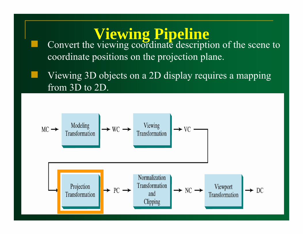
Viewing PipelineThe general processing steps for modeling and converting a world coordinate description of a scene to device coordinates:

Viewing Pipeline1. Construct the shape of individual objects in a scene
within modeling coordinate, and place the objects into appropriate positions within the scene (world coordinate).
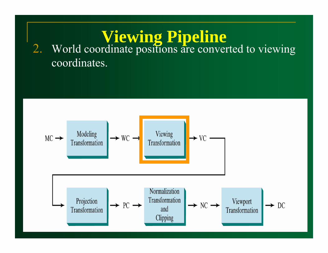
Viewing Pipeline2. World coordinate positions are converted to viewing
coordinates.
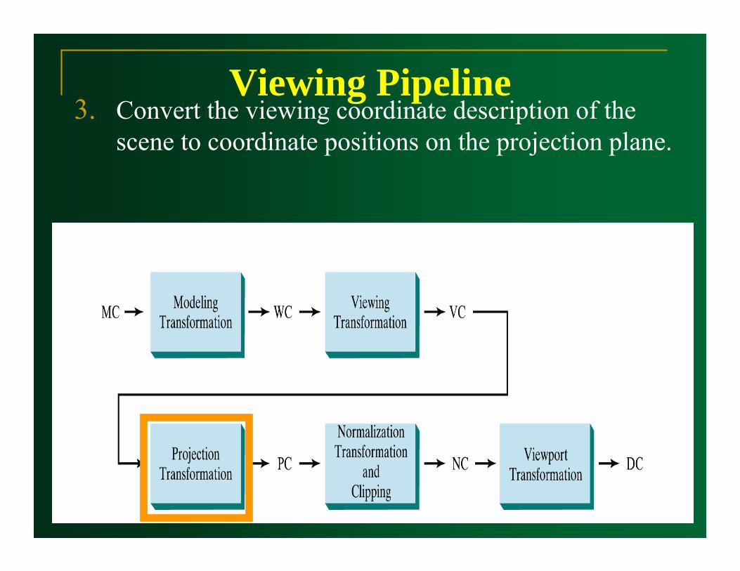
Viewing Pipeline3. Convert the viewing coordinate description of the
scene to coordinate positions on the projection plane.
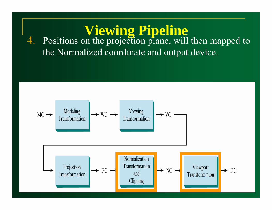
Viewing Pipeline4. Positions on the projection plane, will then mapped to
the Normalized coordinate and output device.
Viewing Coordinates
Camera Analogy
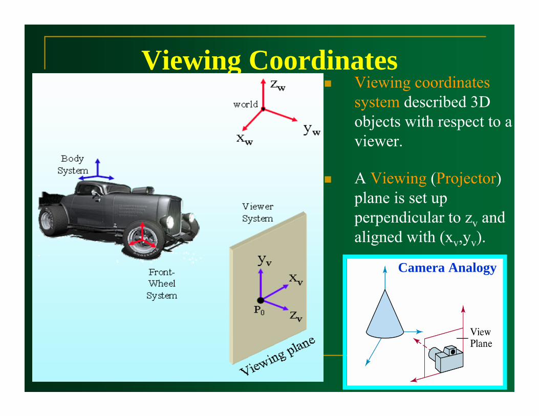
Viewing coordinates system described 3D objects with respect to a viewer.
A Viewing (Projector) plane is set up perpendicular to zv and aligned with (xv,yv).
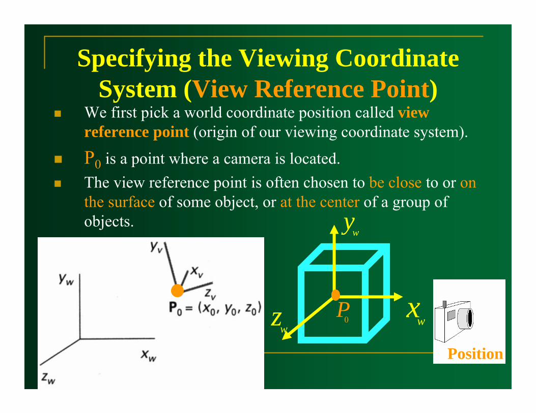
Specifying the Viewing Coordinate System (View Reference Point)
We first pick a world coordinate position called view reference point (origin of our viewing coordinate system).
P0 is a point where a camera is located.The view reference point is often chosen to be close to or on the surface of some object, or at the center of a group of objects.
wx
wy
wz 0P
Position
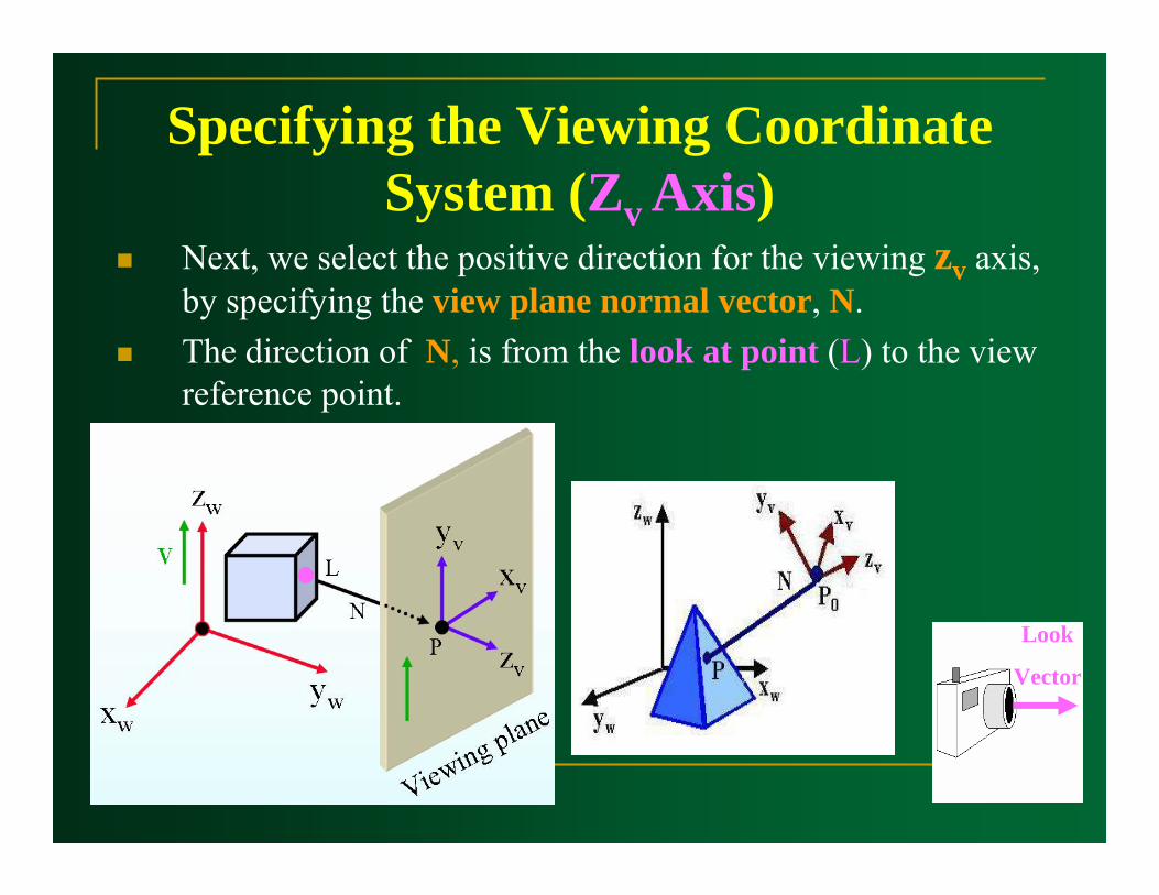
Specifying the Viewing Coordinate System (Zv Axis)
Next, we select the positive direction for the viewing zv axis, by specifying the view plane normal vector, N.The direction of N, is from the look at point (L) to the view reference point.
Look
Vector
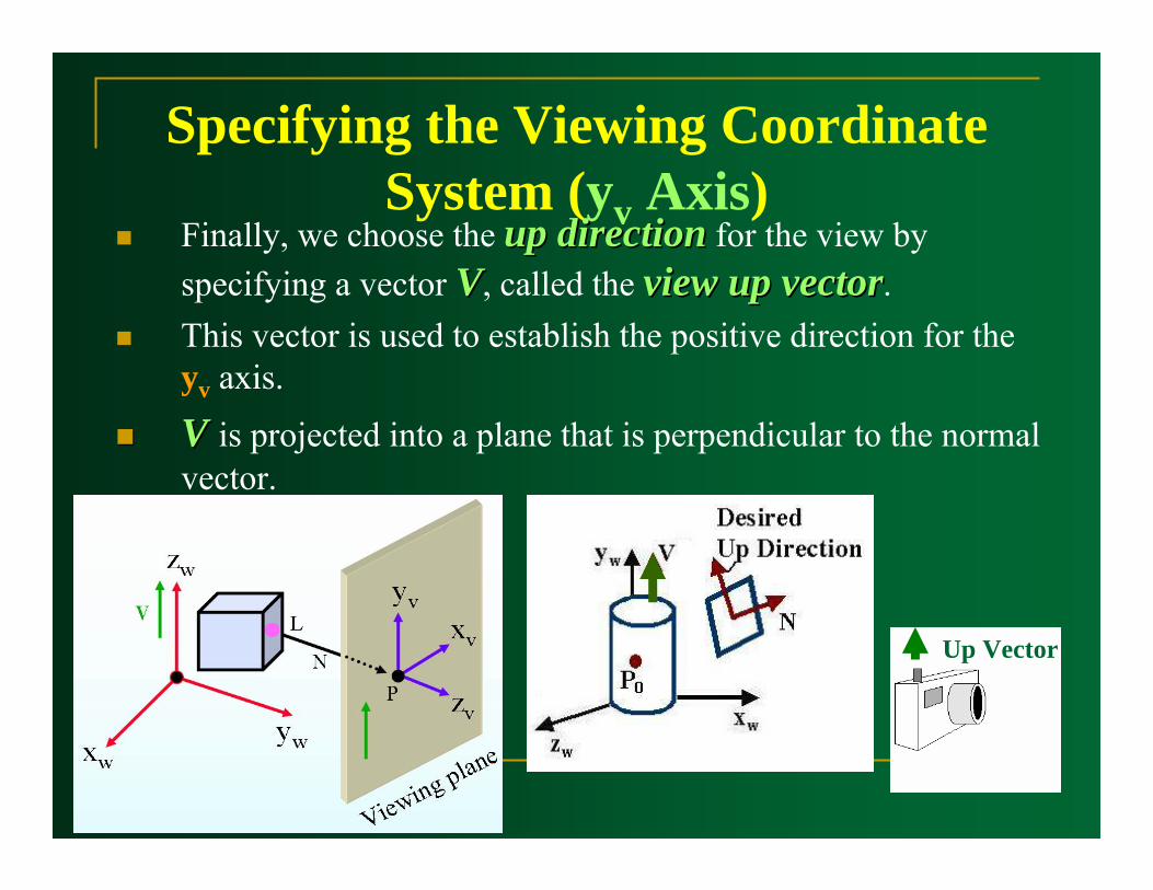
Specifying the Viewing Coordinate System (yv Axis)
Finally, we choose the up directionup direction for the view by specifying a vector VV, called the view up vectorview up vector.This vector is used to establish the positive direction for the yv axis.
V V is projected into a plane that is perpendicular to the normal vector.
Up Vector
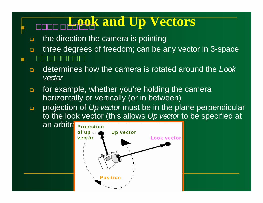
Look and Up Vectors the direction the camera is pointingthree degrees of freedom; can be any vector in 3-space
determines how the camera is rotated around the Look vectorfor example, whether you’re holding the camera horizontally or vertically (or in between)projection of Up vector must be in the plane perpendicular to the look vector (this allows Up vector to be specified at an arbitrary angle to its Look vector)
Up vectorLook vector
Projection of up vector
Position
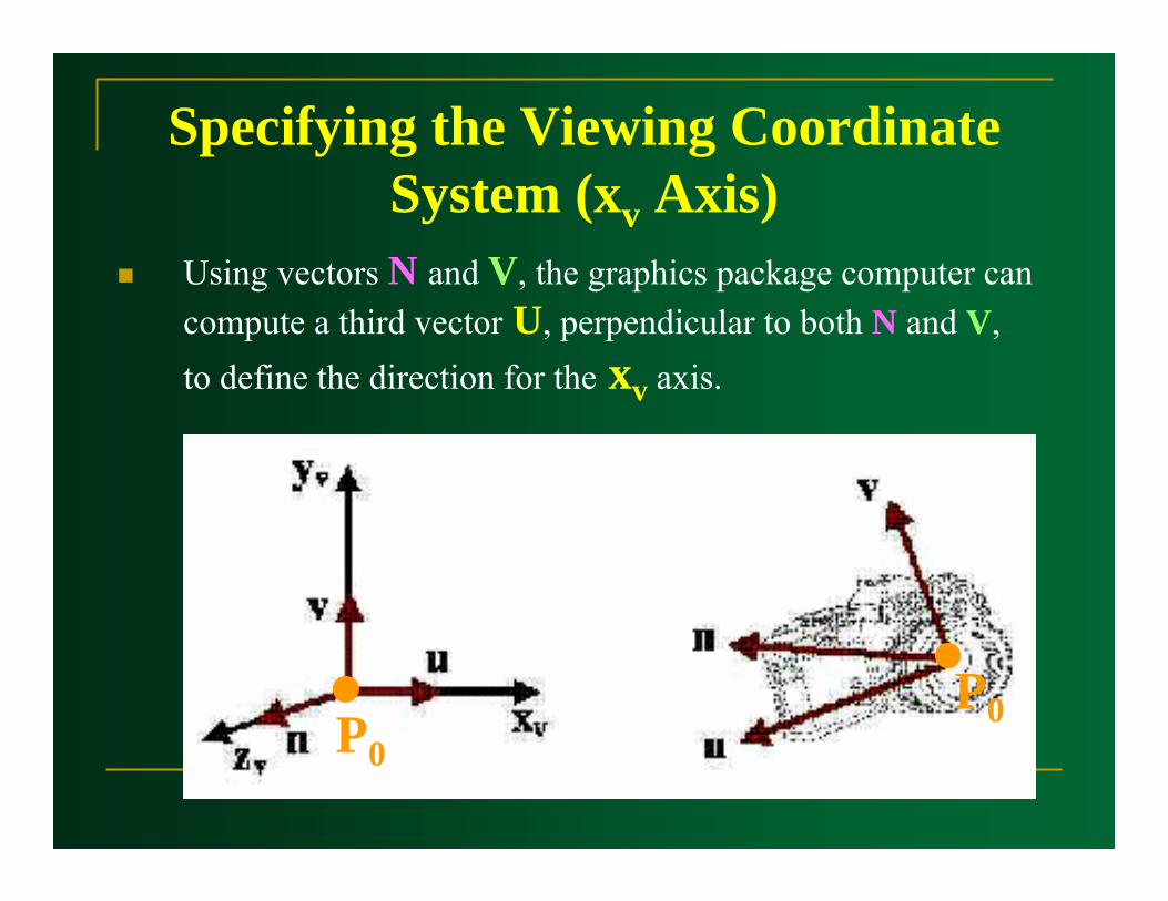
Specifying the Viewing Coordinate System (xv Axis)
Using vectors N and V, the graphics package computer can compute a third vector U, perpendicular to both N and V, to define the direction for the xv axis.
P0P0
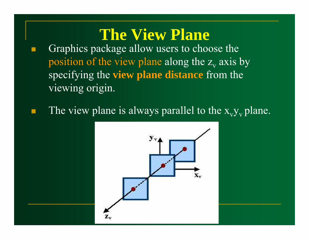
The View PlaneGraphics package allow users to choose the position of the view plane along the zv axis by specifying the view plane distance from the viewing origin.
The view plane is always parallel to the xvyv plane.
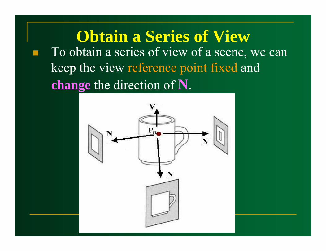
Obtain a Series of ViewTo obtain a series of view of a scene, we can keep the view reference point fixed and change the direction of N.

Simulate Camera MotionTo simulate camera motion through a scene, we can keep N fixed and move the view reference point around.
Transformation from World to Viewing
Coordinates
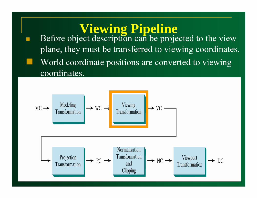
Viewing PipelineBefore object description can be projected to the view plane, they must be transferred to viewing coordinates.World coordinate positions are converted to viewing coordinates.
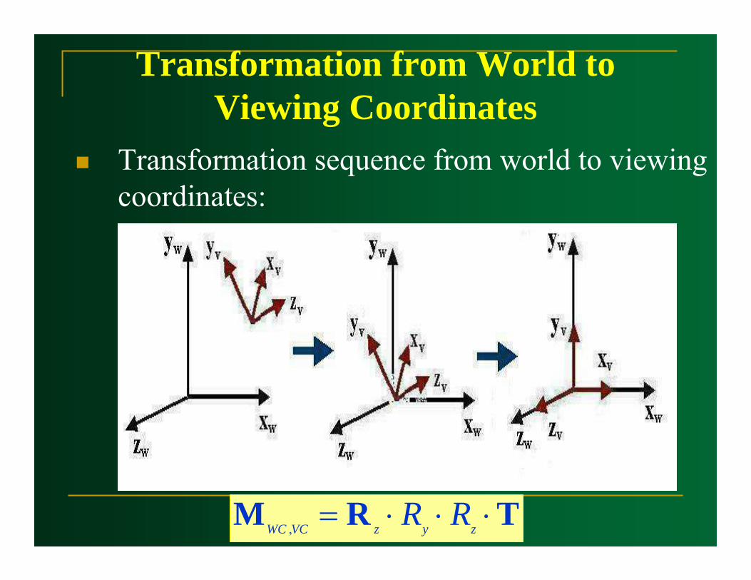
Transformation from World to Viewing Coordinates
Transformation sequence from world to viewing coordinates:
TRM ⋅⋅⋅= zyzVCWC RR,
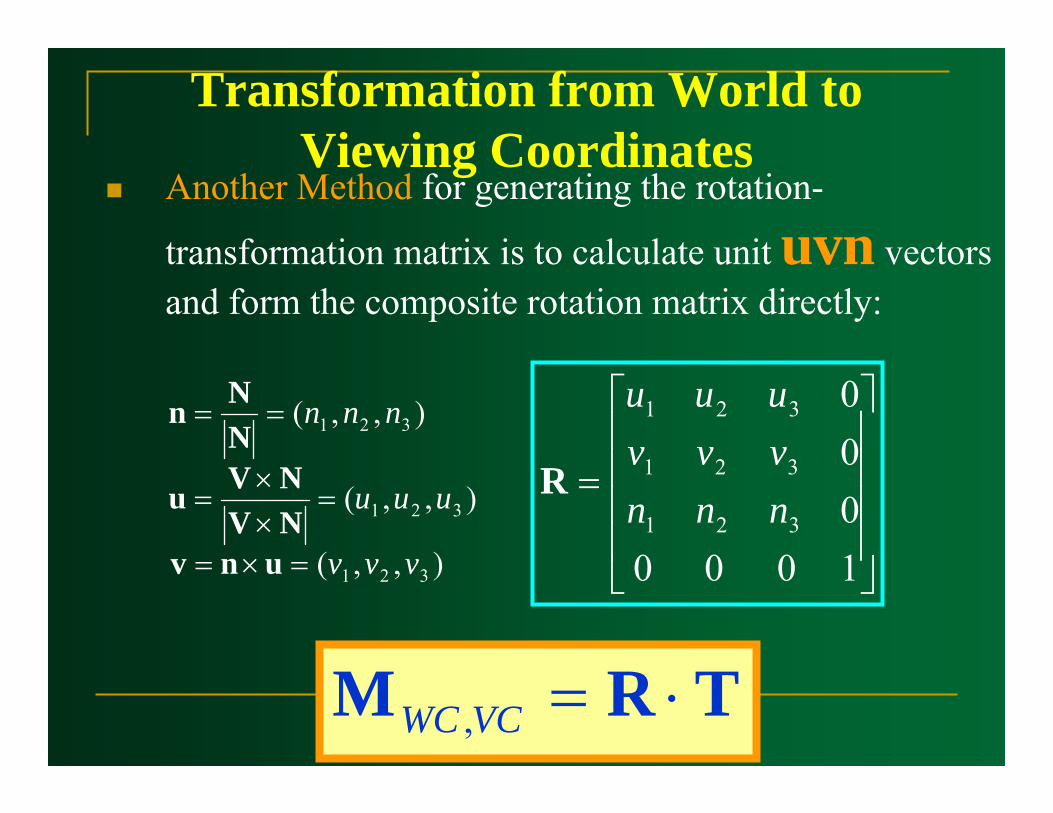
Transformation from World to Viewing Coordinates
Another Method for generating the rotation-
transformation matrix is to calculate unit uvn vectors and form the composite rotation matrix directly:
),,(
),,(
),,(
321
321
321
vvv
uuu
nnn
=×=
=××
=
==
unvNVNVu
NNn
⎥⎥⎥⎥
⎦
⎤
⎢⎢⎢⎢
⎣
⎡
=
1000000
321
321
321
nnnvvvuuu
R
TRM ⋅=VCWC ,
Projection
Viewing PipelineConvert the viewing coordinate description of the scene to coordinate positions on the projection plane.
Viewing 3D objects on a 2D display requires a mapping from 3D to 2D.

ProjectionProjection can be defined as a mapping of point P(x,y,z) onto its image in the projection plane.
The mapping is determined by a projectorprojector that passes through P and intersects the view plane ( ).
),,( zyxP ′′′′
P′
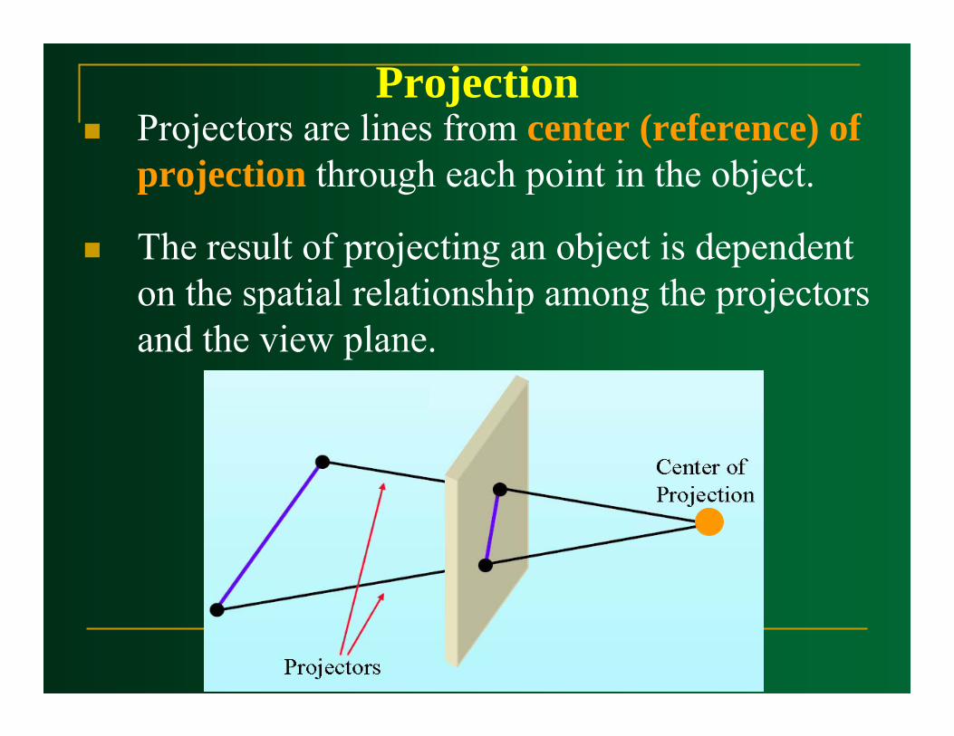
ProjectionProjectors are lines from center (reference) of projection through each point in the object.
The result of projecting an object is dependent on the spatial relationship among the projectors and the view plane.
Projection
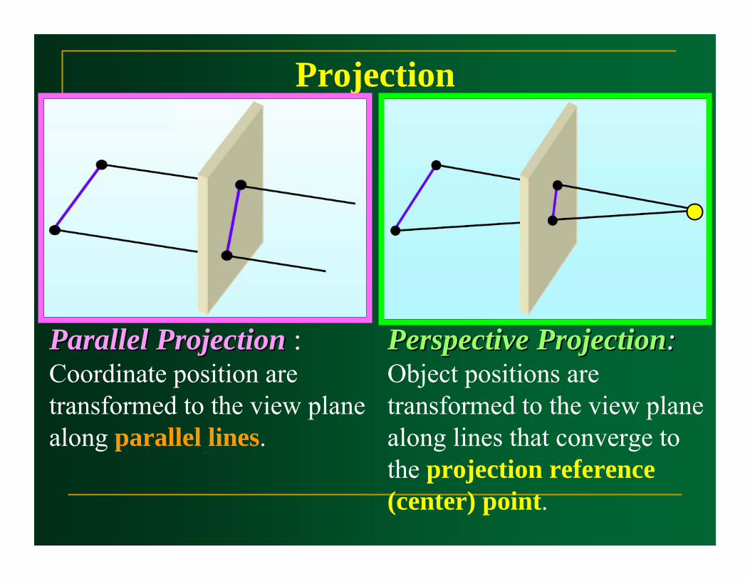
Parallel ProjectionParallel Projection : Coordinate position are transformed to the view plane along parallel lines.
Perspective ProjectionPerspective Projection: : Object positions are transformed to the view plane along lines that converge to the projection reference (center) point.
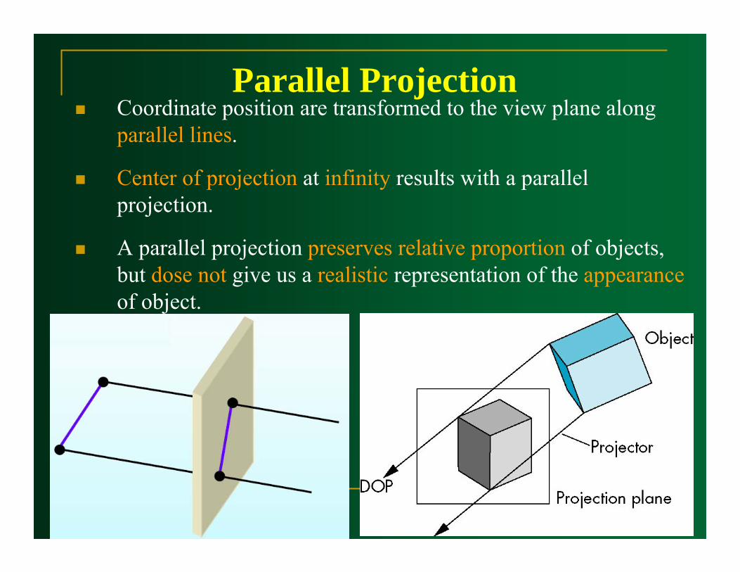
Parallel ProjectionCoordinate position are transformed to the view plane along parallel lines.
Center of projection at infinity results with a parallel projection.
A parallel projection preserves relative proportion of objects, but dose not give us a realistic representation of the appearanceof object.
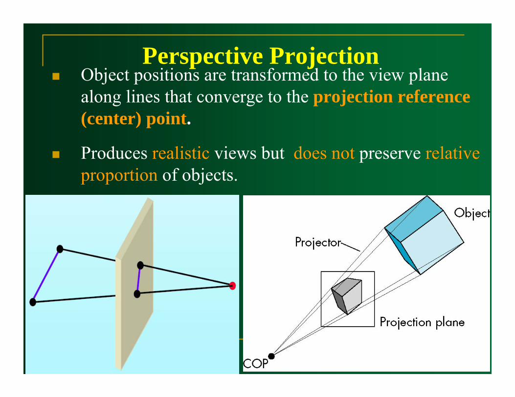
Perspective ProjectionObject positions are transformed to the view plane along lines that converge to the projection reference (center) point.
Produces realistic views but does not preserve relative proportion of objects.
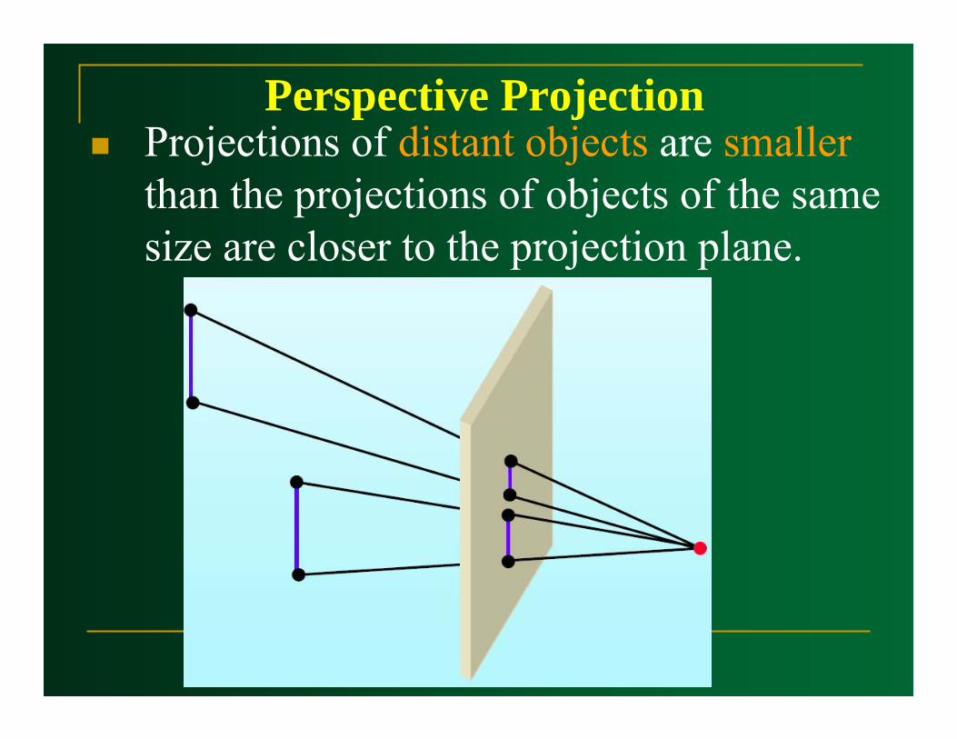
Perspective ProjectionProjections of distant objects are smallerthan the projections of objects of the same size are closer to the projection plane.
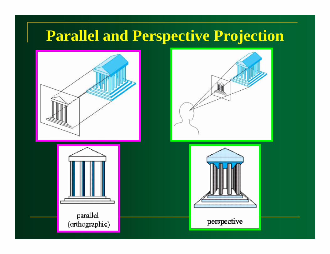
Parallel and Perspective Projection

Parallel Projection
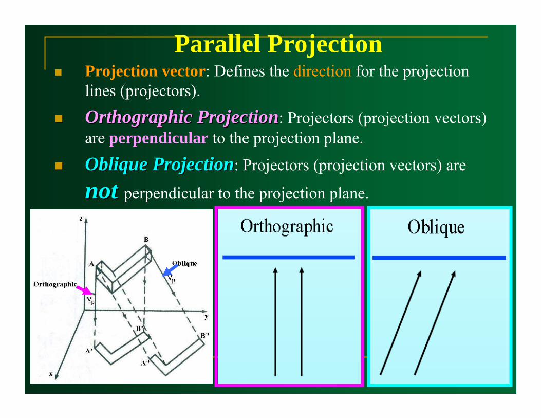
Parallel ProjectionProjection vector: Defines the direction for the projection lines (projectors).
Orthographic ProjectionOrthographic Projection: Projectors (projection vectors) are perpendicular to the projection plane.
Oblique ProjectionOblique Projection: Projectors (projection vectors) are
not not perpendicular to the projection plane.
OrthographicParallel Projection

Orthographic Parallel ProjectionOrthographic projection used to produce the front, side, and top views of an object.
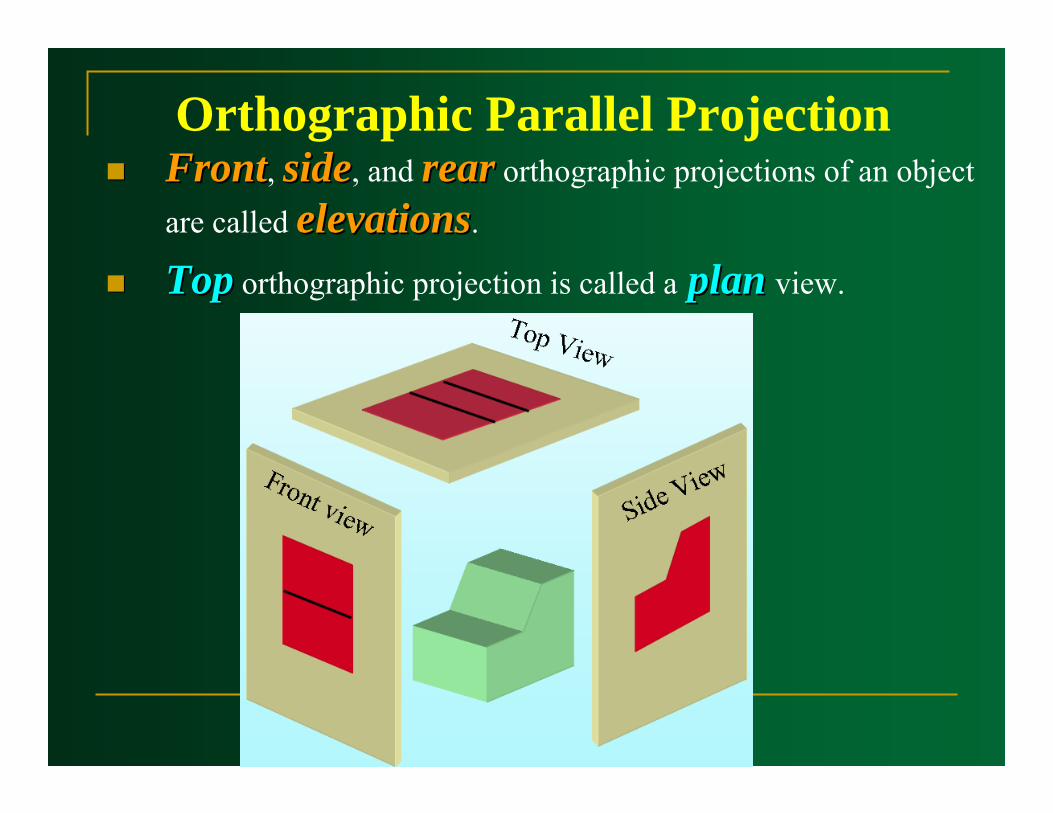
Orthographic Parallel ProjectionFrontFront, sideside, and rearrear orthographic projections of an object are called elevationselevations.
TopTop orthographic projection is called a planplan view.
Orthographic Parallel Projection
�������� �yyyyyyyy y�������� �yyyyyyyy y
�������� �yyyyyyyy y�������� �yyyyyyyy y
������������������
��yyyyyyyyyyyyyyyyyy
yy ���������
�yyyyyyyyy
y���������
�yyyyyyyyy
y ���������
�yyyyyyyyy
y
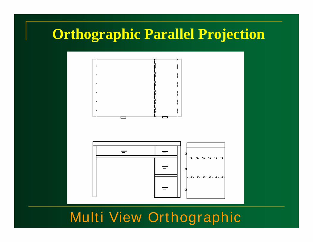
Multi View Orthographic
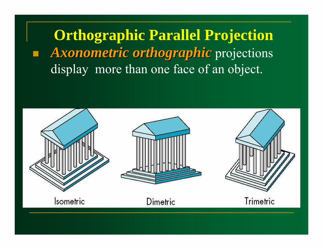
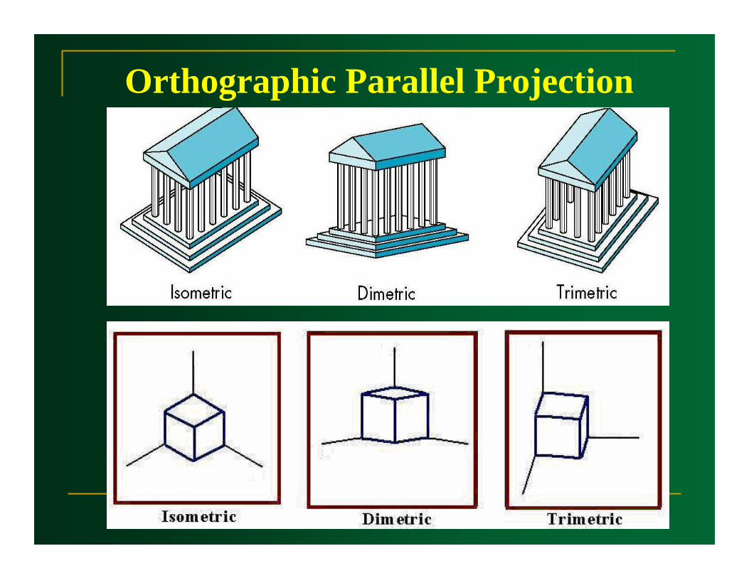
Orthographic Parallel ProjectionAxonometric orthographicAxonometric orthographic projections display more than one face of an object.
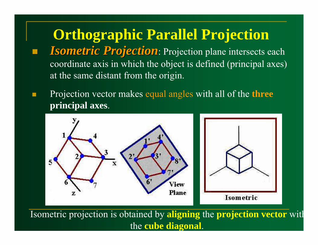
Orthographic Parallel ProjectionIsometric ProjectionIsometric Projection: Projection plane intersects each coordinate axis in which the object is defined (principal axes) at the same distant from the origin.
Projection vector makes equal angles with all of the three principal axes.
Isometric projection is obtained by aligning the projection vector withthe cube diagonal.
Orthographic Parallel Projection
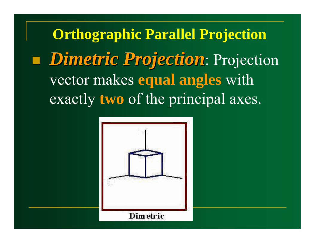
DimetricDimetric ProjectionProjection: Projection vector makes equal angles with exactly two of the principal axes.

Orthographic Parallel Projection
Trimetric ProjectionTrimetric Projection: Projection vector makes unequal angles with the three principal axes.
Orthographic Parallel Projection
Orthographic Parallel Projection
Transformation
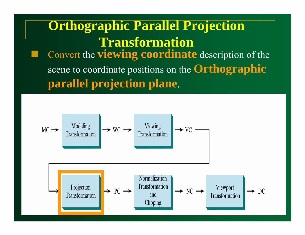
Convert the viewing coordinate description of the scene to coordinate positions on the Orthographic parallel projection plane.
Orthographic Parallel Projection Transformation
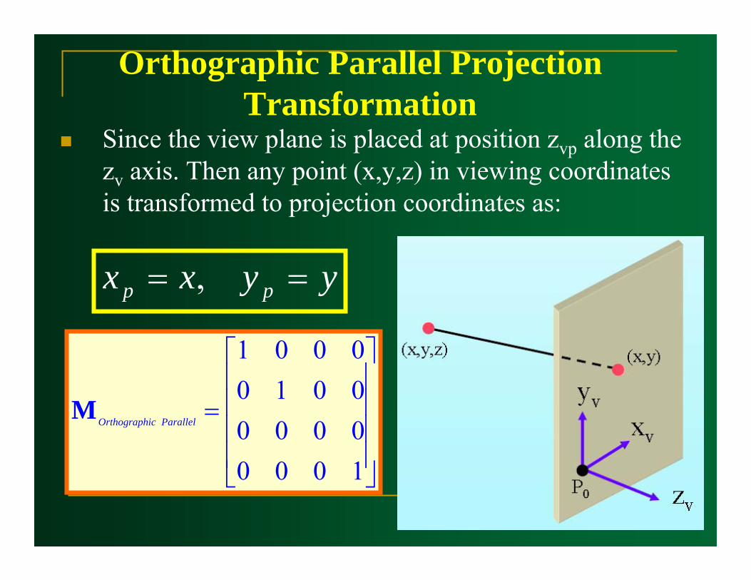
Since the view plane is placed at position zvp along the zv axis. Then any point (x,y,z) in viewing coordinates is transformed to projection coordinates as:
Orthographic Parallel Projection Transformation
⎥⎥⎥⎥
⎦
⎤
⎢⎢⎢⎢
⎣
⎡
=
1000000000100001
ParallelicOrthographM
yyxx pp == ,
ObliqueParallel Projection
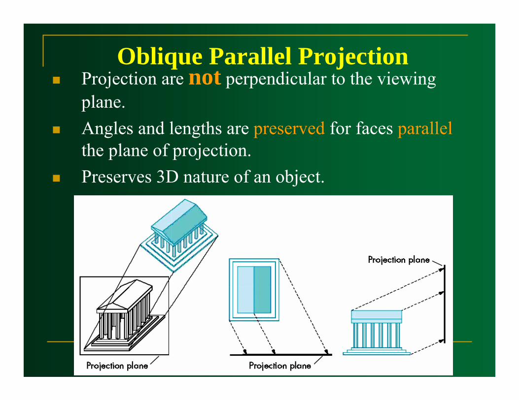
Oblique Parallel ProjectionProjection are not perpendicular to the viewing plane.Angles and lengths are preserved for faces parallelthe plane of projection.Preserves 3D nature of an object.
ObliqueParallel Projection
Transformation
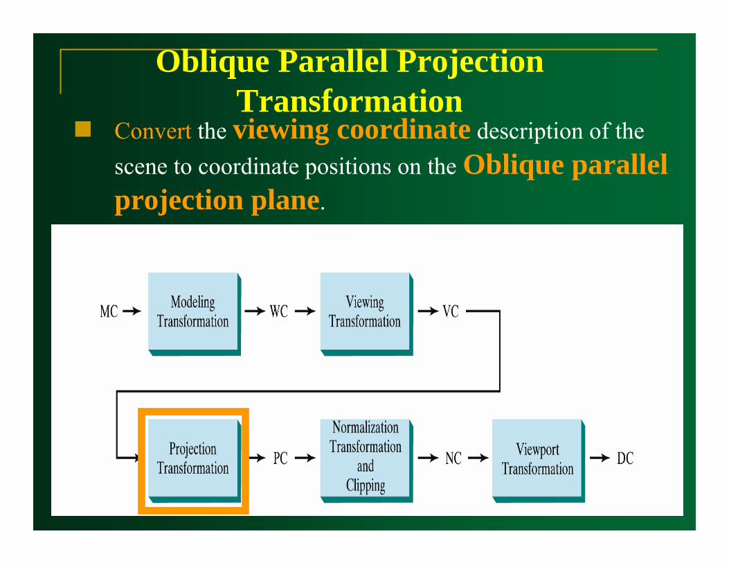
Convert the viewing coordinate description of the scene to coordinate positions on the Oblique parallel projection plane.
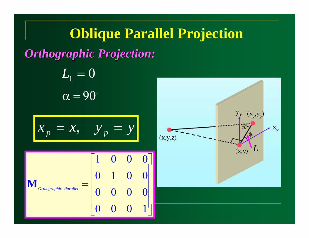
Oblique Parallel Projection Transformation
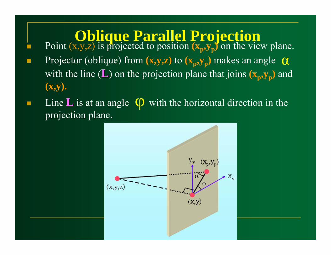
Oblique Parallel ProjectionPoint (x,y,z) is projected to position (xp,yp) on the view plane.Projector (oblique) from (x,y,z) to (xp,yp) makes an angle with the line (LL) on the projection plane that joins (xp,yp) and (x,y).
Line LL is at an angle with the horizontal direction in the projection plane.
α
φ
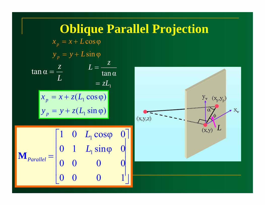
Oblique Parallel Projection
φsin
φcos
Lyy
Lxx
p
p
+=
+=
Lz
=αtan1 αtan
zL
zL
=
=
)φsin(
)φcos(
1
1
Lzyy
Lzxx
p
p
+=
+=
⎥⎥⎥⎥
⎦
⎤
⎢⎢⎢⎢
⎣
⎡
=
100000000φsin100φcos01
1
1
LL
ParallelM
L
Oblique Parallel Projection
L
01 =LOrthographic Projection:Orthographic Projection:
o90=α
⎥⎥⎥⎥
⎦
⎤
⎢⎢⎢⎢
⎣
⎡
=
1000000000100001
ParallelicOrthographM
yyxx pp == ,
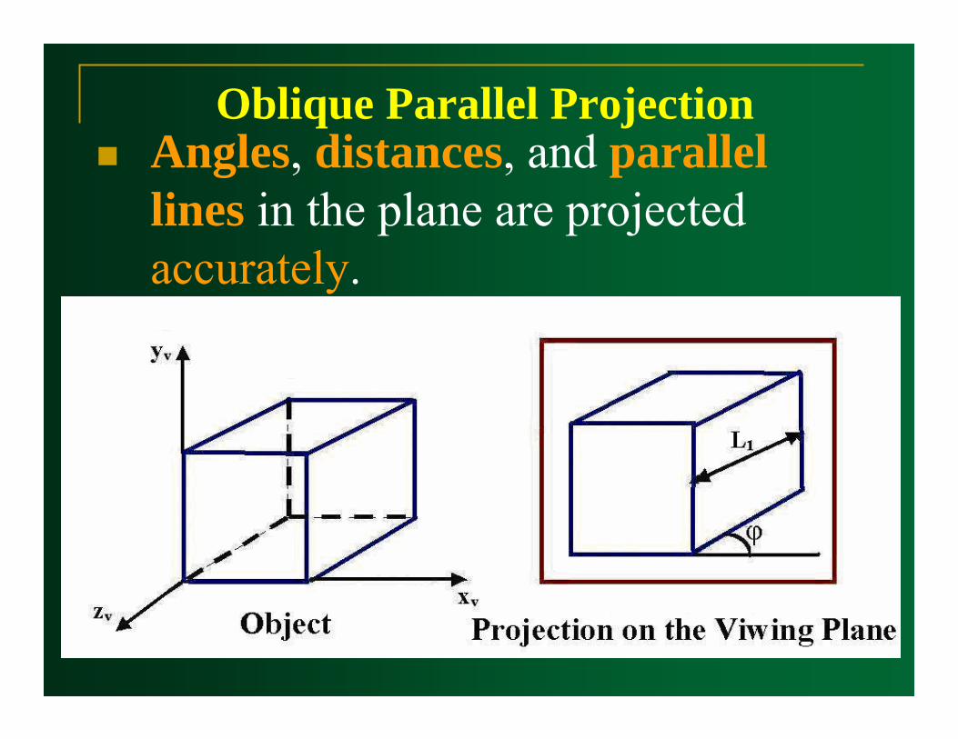
Oblique Parallel ProjectionAngles, distances, and parallel lines in the plane are projected accurately.
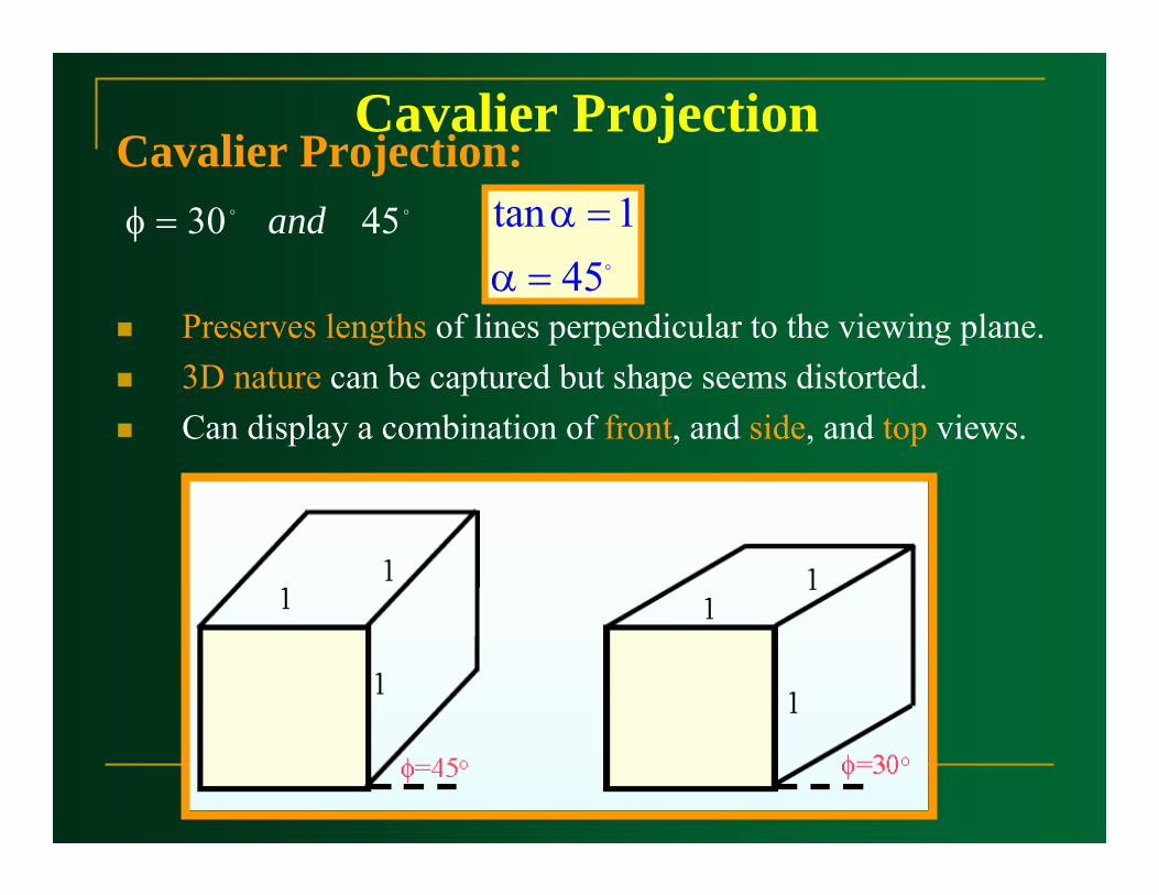
Cavalier ProjectionCavalier Projection:
Preserves lengths of lines perpendicular to the viewing plane.3D nature can be captured but shape seems distorted.Can display a combination of front, and side, and top views.
oo 4530 and=φo451tan
=α=α
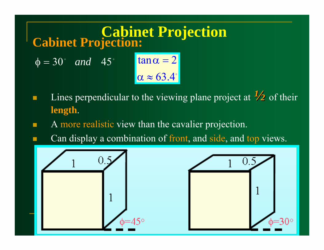
Cabinet ProjectionCabinet Projection:
Lines perpendicular to the viewing plane project at ½½ of their length.A more realistic view than the cavalier projection.Can display a combination of front, and side, and top views.
o4.632tan
≈α=αoo 4530 and=φ

Cavalier & Cabinet Projection
Cavalier Cabinet
Perspective Projection
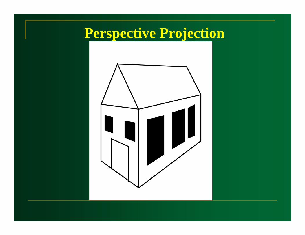
Perspective Projection
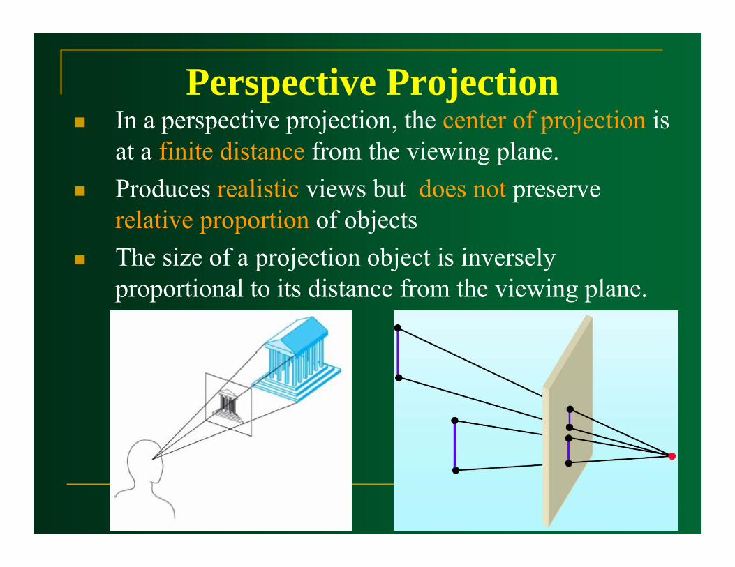
Perspective ProjectionIn a perspective projection, the center of projection is at a finite distance from the viewing plane.Produces realistic views but does not preserve relative proportion of objects The size of a projection object is inversely proportional to its distance from the viewing plane.
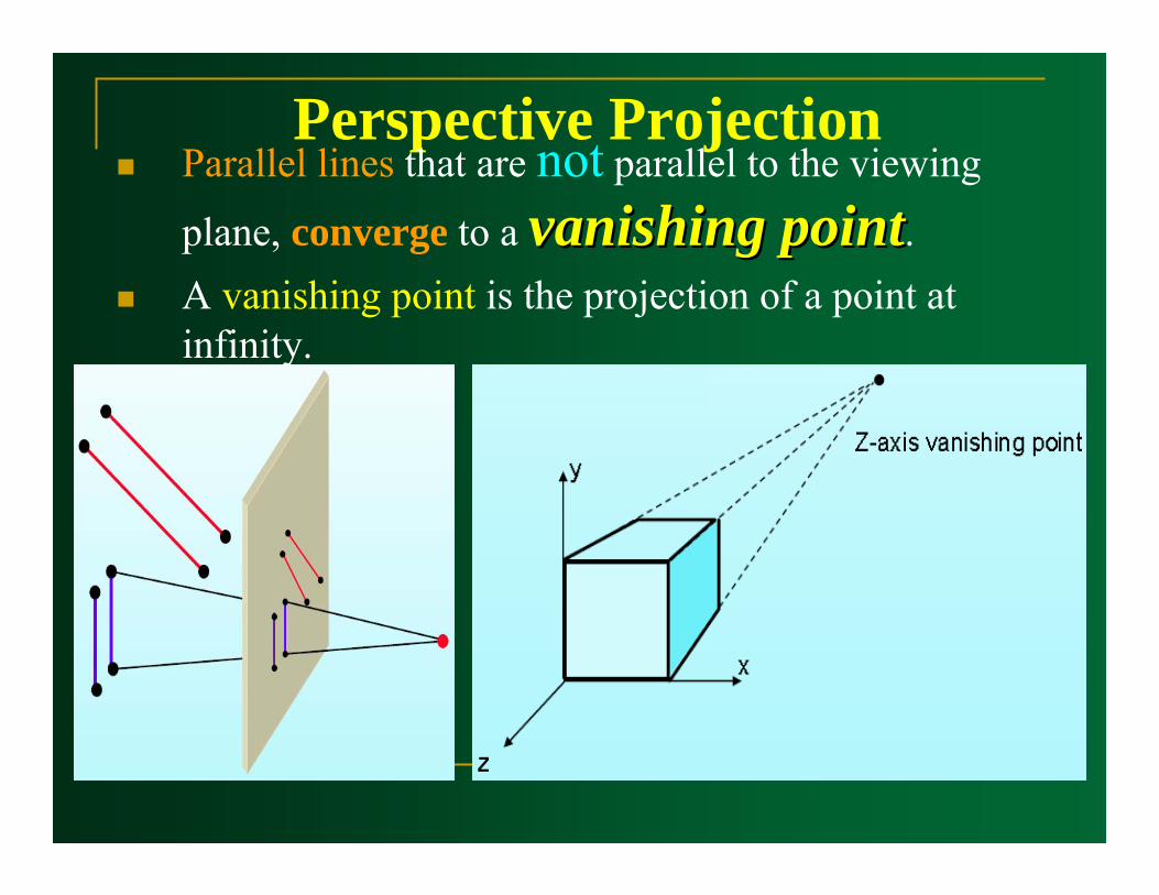
Perspective ProjectionParallel lines that are not parallel to the viewing
plane, converge to a vanishing pointvanishing point.A vanishing point is the projection of a point at infinity.

Vanishing PointsEach set of projected parallel lines will have a separate vanishing points.There are infinity many general vanishing points.
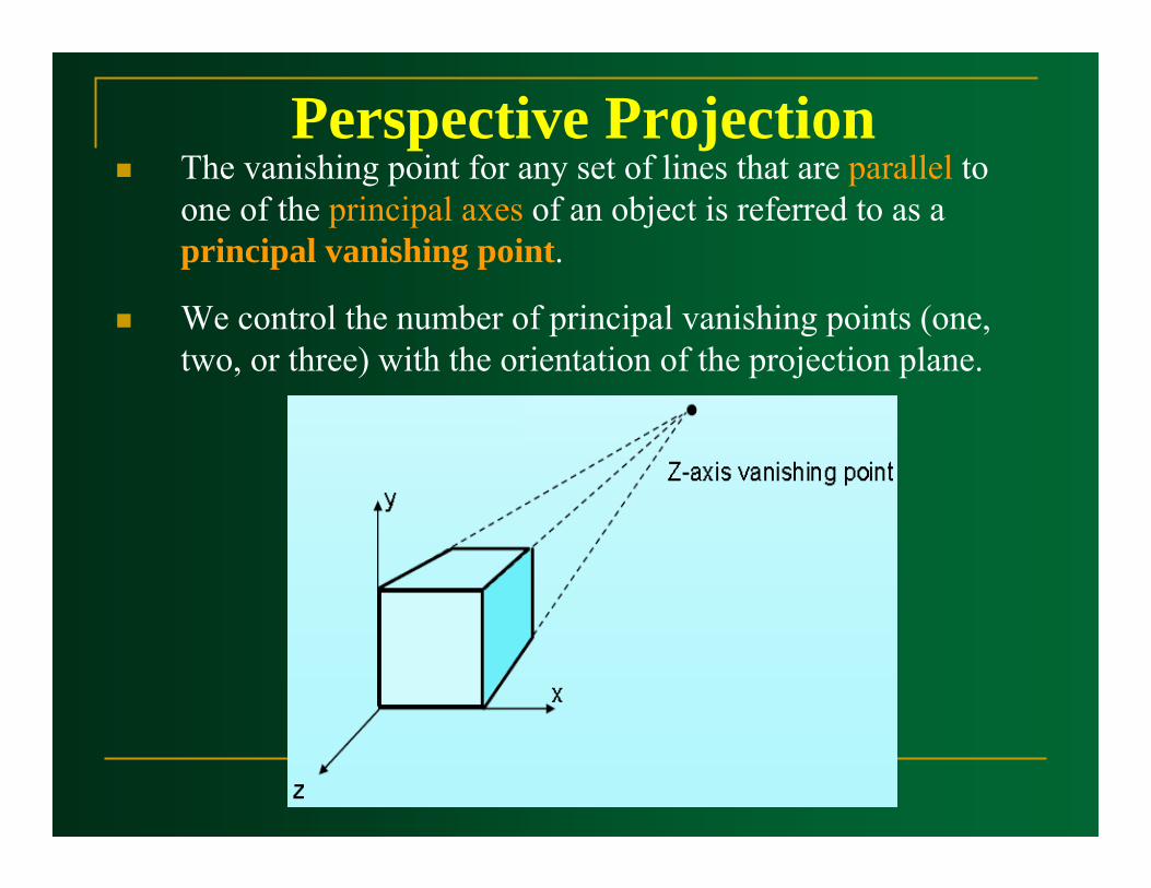
Perspective ProjectionThe vanishing point for any set of lines that are parallel to one of the principal axes of an object is referred to as a principal vanishing point.
We control the number of principal vanishing points (one, two, or three) with the orientation of the projection plane.

Perspective ProjectionThe number of principal vanishing points in a projection is determined by the number of principal axes intersecting the view plane.
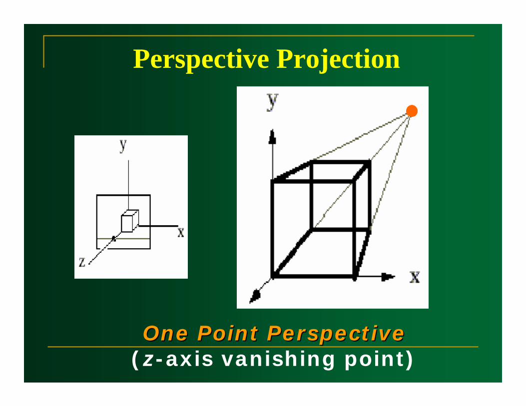
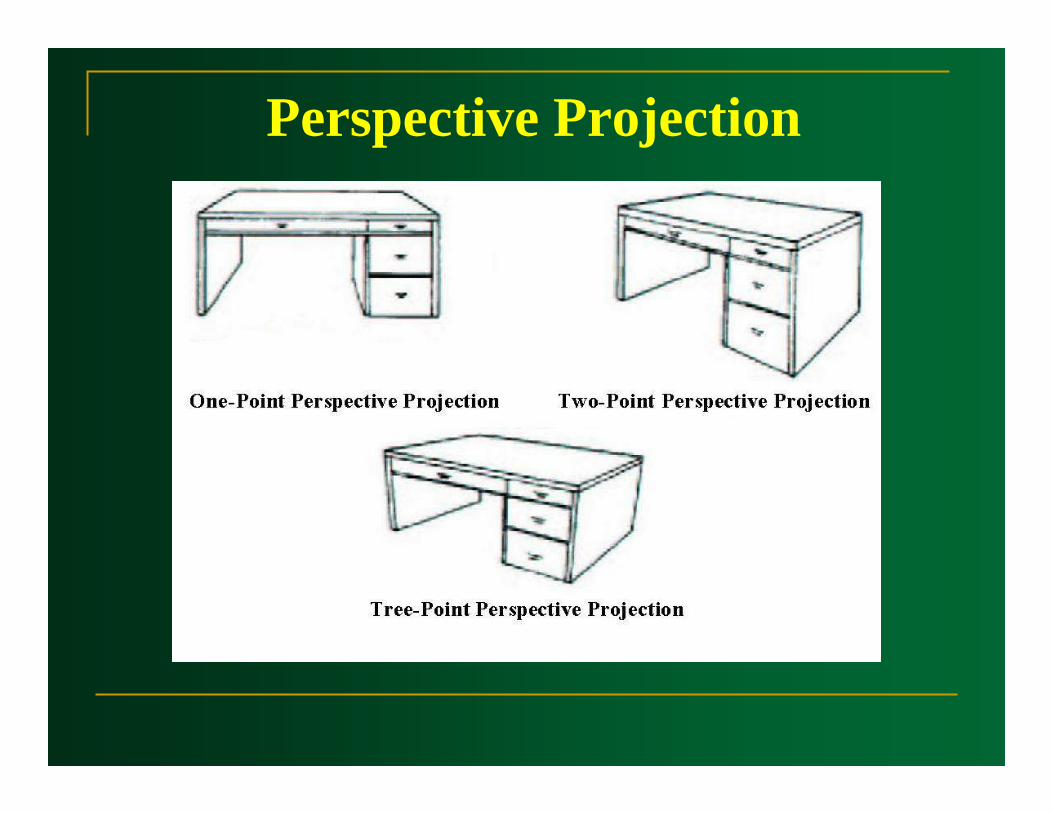
Perspective Projection
One Point PerspectiveOne Point Perspective(z-axis vanishing point)
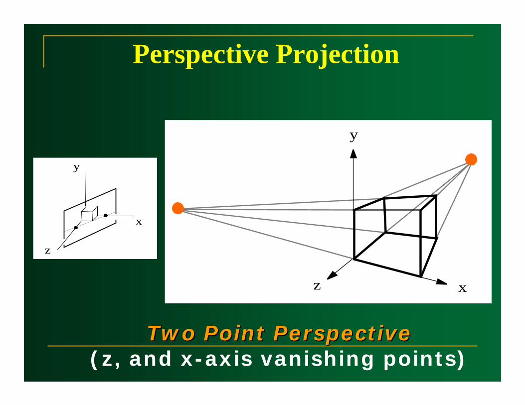
Perspective Projection
Two Point Perspective Two Point Perspective (z, and x-axis vanishing points)
y
xz
y
x
z
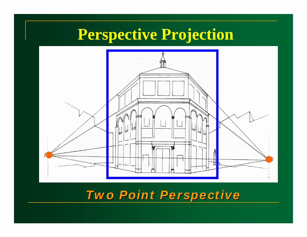
Perspective Projection
Two Point Perspective Two Point Perspective

Perspective Projection
ThreeThree Point PerspectivePoint Perspective(z, x, and y-axis vanishing points)
y
z
x
y
xz
Perspective Projection

Perspective Projection Transformation
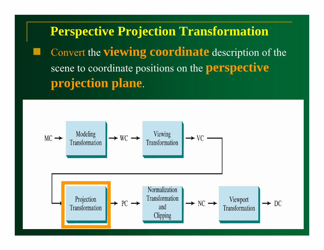
Convert the viewing coordinate description of the scene to coordinate positions on the perspective projection plane.
Perspective Projection Transformation
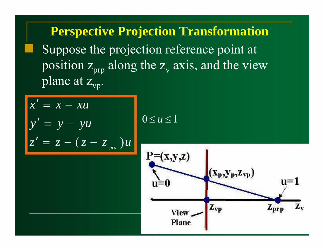
Suppose the projection reference point at position zprp along the zv axis, and the view plane at zvp.
Perspective Projection Transformation
uzzzzyuyyxuxx
prp )( −−=′−=′−=′
10 ≤≤ u
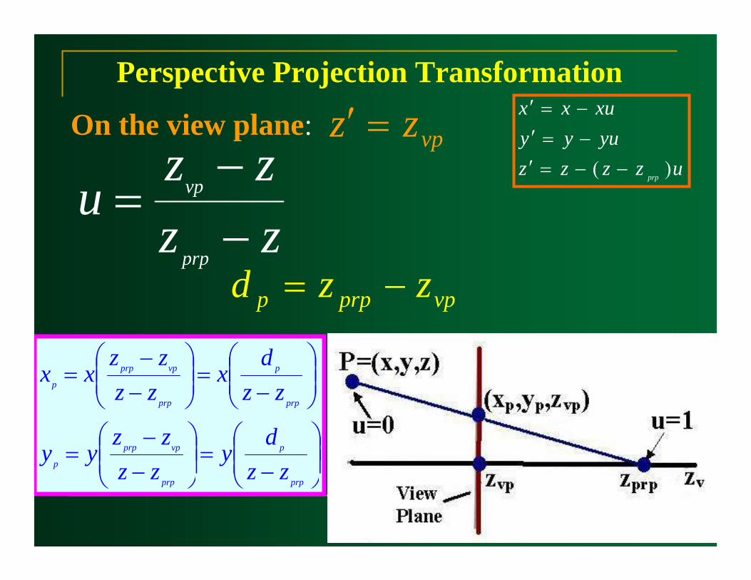
Perspective Projection Transformation
uzzzzyuyyxuxx
prp )( −−=′−=′−=′
vpzz =′
zzzz
uprp
vp
−−
=
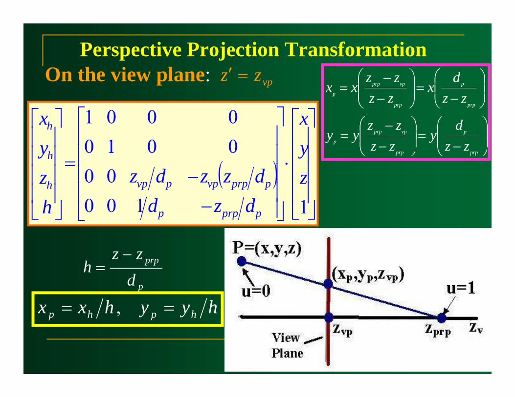
On the view plane:
⎟⎟⎠
⎞⎜⎜⎝
⎛−
=⎟⎟⎠
⎞⎜⎜⎝
⎛−−
=
⎟⎟⎠
⎞⎜⎜⎝
⎛−
=⎟⎟⎠
⎞⎜⎜⎝
⎛−−
=
prp
p
prp
vpprp
p
prp
p
prp
vpprp
p
zzd
yzzzz
yy
zzd
xzzzz
xx
vpprpp zzd −=
Perspective Projection Transformationvpzz =′On the view plane:
⎟⎟⎠
⎞⎜⎜⎝
⎛−
=⎟⎟⎠
⎞⎜⎜⎝
⎛−−
=
⎟⎟⎠
⎞⎜⎜⎝
⎛−
=⎟⎟⎠
⎞⎜⎜⎝
⎛−−
=
prp
p
prp
vpprp
p
prp
p
prp
vpprp
p
zzd
yzzzz
yy
zzd
xzzzz
xx
( )⎥⎥⎥⎥
⎦
⎤
⎢⎢⎢⎢
⎣
⎡
⋅
⎥⎥⎥⎥⎥
⎦
⎤
⎢⎢⎢⎢⎢
⎣
⎡
−−
=
⎥⎥⎥⎥
⎦
⎤
⎢⎢⎢⎢
⎣
⎡
110000
00100001
zyx
dzddzzdz
hzyx
pprpp
pprpvppvph
h
h
p
prp
dzz
h−
=
hyyhxx hphp == ,

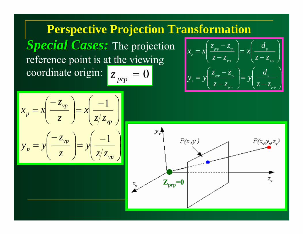
Perspective Projection TransformationSpecial Cases:Special Cases: 0=vpz
⎟⎟⎠
⎞⎜⎜⎝
⎛
−=⎟
⎟⎠
⎞⎜⎜⎝
⎛
−=
⎟⎟⎠
⎞⎜⎜⎝
⎛
−=⎟
⎟⎠
⎞⎜⎜⎝
⎛
−=
11
11
prpprp
prpp
prpprp
prpp
zzy
zzz
yy
zzx
zzz
xx ⎟⎟⎠
⎞⎜⎜⎝
⎛−
=⎟⎟⎠
⎞⎜⎜⎝
⎛−−
=
⎟⎟⎠
⎞⎜⎜⎝
⎛−
=⎟⎟⎠
⎞⎜⎜⎝
⎛−−
=
prp
p
prp
vpprp
p
prp
p
prp
vpprp
p
zzd
yzzzz
yy
zzd
xzzzz
xx
⎟⎟⎠
⎞⎜⎜⎝
⎛−
=⎟⎟⎠
⎞⎜⎜⎝
⎛−−
=
⎟⎟⎠
⎞⎜⎜⎝
⎛−
=⎟⎟⎠
⎞⎜⎜⎝
⎛−−
=
prp
p
prp
vpprp
p
prp
p
prp
vpprp
p
zzd
yzzzz
yy
zzd
xzzzz
xx
Perspective Projection TransformationSpecial Cases:Special Cases: The projection reference point is at the viewing coordinate origin: 0=prpz
Zprp=0
⎟⎟⎠
⎞⎜⎜⎝
⎛ −=⎟⎟
⎠
⎞⎜⎜⎝
⎛ −=
⎟⎟⎠
⎞⎜⎜⎝
⎛ −=⎟⎟
⎠
⎞⎜⎜⎝
⎛ −=
vp
vpp
vp
vpp
zzy
zz
yy
zzx
zz
xx
1
1

Summery
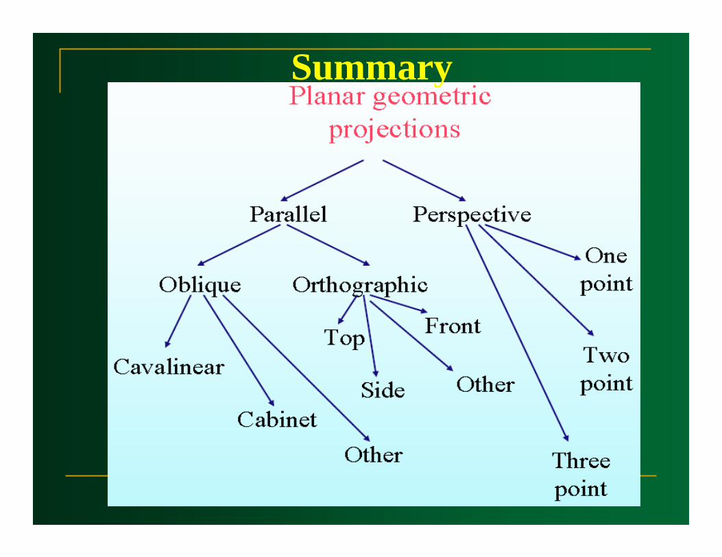
Summary