Embed Size (px)
Citation preview
Three-dimensional shape measurement of adiffusing surface by use of a femtosecondamplifying optical Kerr gate
Takeshi Yasui, Kaoru Minoshima, and Hirokazu Matsumoto
We propose a system for three-dimensional ~3D! shape measurement of a diffusing surface by use of apreviously developed femtosecond amplifying optical Kerr gate ~fs-amp OKG!. The system has anopening time of 459 fs and a maximum transmittance of 185%. It also provides good 3D imagingperformance: a transverse imaging resolution of 70 mm, a depth resolution of 100 mm, and a positioningaccuracy of 5.9 mm in depth. It is found that the optical Kerr effect and the amplification process in thefs-amp OKG do not cause the quality of a time-resolved image to deteriorate. We prove the effectivenessof the proposed system by measuring the shapes of completely diffusing objects with stepped andspherical surfaces. © 2000 Optical Society of America
OCIS codes: 170.6920, 170.7160, 110.6880, 190.4360, 120.6650, 120.6660.
tha
1. Introduction
Optical shape measurement is important for manyfields, including science and industrial applications.Because practical objects are not always ideal sub-jects for optical measurements, various measurementmethods have been investigated that depend on theobjects to be measured. For industrial inspectionsthere is considerable need for shape measurement ofa diffusing surface, such as a rough metallic surface.At present, ~1! light sectioning,1,2 ~2! moire topogra-phy,3,4 and ~3! holography5 are available for suchneeds. However, there are several limits to practi-cal use of these methods: ~1! gentle curvature ofsurface and scanning, ~2! low sensitivity, and ~3! im-possibility of real-time measurement, respectively.
Ultrafast time-resolved imaging provides interest-ing tools for shape measurements of an object.6–14
Two-dimensional ~2D! imaging of a moving object,such as observation of ultrafast phenomena, has beenreported.8,11 Conversion of the space axis into a
When this research was performed, the authors were with theNational Research Laboratory of Metrology, 1-1-4 Umezono,Tsukuba, Ibaraki 305-8563, Japan. T. Yasui is now with theDepartment of Systems and Human Science, Osaka University,1-3 Machikaneyama, Toyonaka, Osaka 560-8531, Japan. K.Minoshima’s e-mail address is [email protected].
Received 14 May 1999; revised manuscript received 30 August1999.
0003-6935y00y010065-07$15.00y0© 2000 Optical Society of America
ime axis by use of the time of flight of an optical pulseas been used to realize three-dimensional ~3D! im-ging of a stationary object.13 There has been a re-
port of a method of measuring a moving 3D object byuse of chirped ultrashort optical pulses.14 Imagingof an object embedded in a diffusing medium can beobtained by use of a temporal gate to extract a realimage signal from multiscattered light.6,7,9,12
The optical Kerr gate ~OKG!, an ultrafast opticalswitch that uses the optical Kerr effect, has severaladvantages as a tool for time-resolved imaging.Real-time 2D imaging and wide spectral bandwidthare possible because the OKG is free from the phase-matching condition and is known to be highly sensi-tive in the picosecond region.11,12 However, whenwe go further into the femtosecond region there is aninherent trade-off between high sensitivity and fastresponse in the conventional OKG, which limits itsperformance in time-resolved imaging. Jonusaus-kas et al. have developed a new method for over-coming this problem in the picosecond region thatuses the optical Kerr effect in an excited state withamplification and two perpendicularly polarizedpump pulses with time delay. They realized anamplifying OKG in the picosecond region by using adye solution.15,16 We have applied these techniquesto femtosecond optical pulses and achieved afemtosecond-amplifying ~fs-amp! OKG.13,17
Our aim in this study is to achieve precise 3D shapemeasurement of a diffusing surface without the needfor a highly sensitive detection device or complicated
1 January 2000 y Vol. 39, No. 1 y APPLIED OPTICS 65
im~
tw~cbbrcp
m
6
image processing. The additional use of a conven-tional highly sensitive detection system, image pro-cessing, or both would help to increase the sensitivityfurther. To apply time-resolved imaging to such ashape measurement requires high sensitivity and ashort gate time. Time-resolved imaging with the op-tical nonlinear effect has the possibility of fulfillingthese requirements. The high peak intensity of fem-tosecond optical pulses provides an efficient opticalnonlinear effect without a thermal effect as well as anincrease of the signal-to-noise ratio in measurement.Light amplification is effective for enhancing thesmall-signal intensity. Although there has beensome research in which stimulated Raman amplifi-cation and optical parametric amplification wereused and highly sensitive time-resolved imaging wasachieved,9,10 their gate times were within the pico-second region. The fs-amp OKG, however, providesboth amplification of the signal and a gate time of theorder of femtoseconds, even though amplificationalone is not so high as in the two former methods.An ultrashort gate time corresponds to high depthresolution in 3D shape measurement by the time-of-flight method. Hence we propose an ultrafast time-resolved imaging system that uses the fs-amp OKGfor 3D shape measurements of a diffusing surface.The basic performance, 3D imaging performance, andapplication of the proposed system were studied ex-perimentally.
2. Experiment
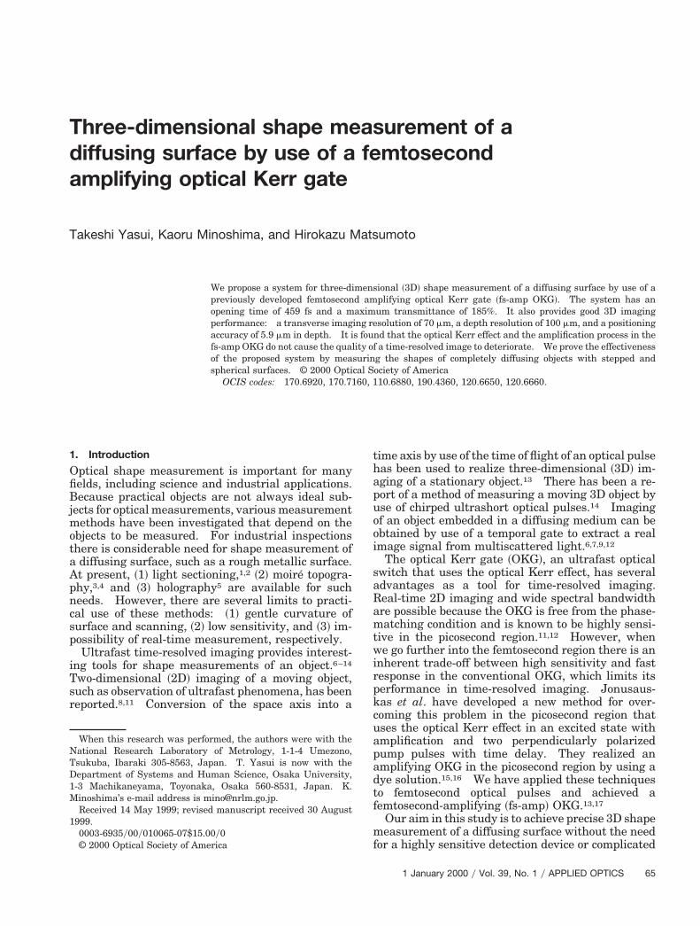
Figure 1 shows an ultrafast time-resolved imaging
Fig. 1. Experimental setup for an ultrafast time-resolved 2D imaL4, L5, and L6, lenses with focal lengths of 100, 100, 220, 100, 50, a
m, b 5 210 mm, c 5 390 mm, d 5 375 mm, e 5 115 mm, f 5 5
6 APPLIED OPTICS y Vol. 39, No. 1 y 1 January 2000
system that uses the fs-amp OKG. The details of thesetup are described elsewhere.13 The light sourcefrom an amplified mode-locked Ti:Al2O3 laser ~cen-tral wavelength, 790 nm; pulse width, 100 fs; pulseenergy, 1 mJ; repetition rate, 100 Hz! is divided intotwo pathways as probe and pump beams. For theapplication of time-resolved spectroscopic 2D imag-ing, a probe light with a broad spectrum is important.The white-continuum ~l 5 350–900 nm! probe beam,mainly because of self-phase modulation in water, isincident onto a sample of the diffusing surface at anangle of 45 deg, and the light diffused from it iseffectively collected by a lens ~L2!. The collected dif-fused light is fed into the OKG ~the gray area in Fig.1! via a collimating lens ~L3! and a polarizer ~P! andmaged onto an optical Kerr and gain material ~OKG
aterial! by a lens ~L4!. Here we used pyridine dyePyridine 1, C19H23N2O4Cl! in an acetonitrile solu-
tion as the OKG material and obtained an efficientoptical Kerr effect in the excited state with amplifi-cation. After recollimation by a lens ~L5!, the probeimage signal is led to an analyzer ~A! perpendicularo the polarizer. The 2D image signal is detectedith a commercial charge-coupled device camera
CCD! through an imaging lens ~L6!. In the appli-ation of time-resolved spectroscopic 2D imaging,oth imaging and spectroscopic information shoulde obtained. We measured a monochromatic time-esolved 2D image by using a bandpass filter ~BPF!entered at 670 nm with a passband of 10 nm and aeak transmission of 50%.To realize an opening time on a femtosecond time
system that uses a fs-amp OKG: BS, beam splitter; L1, L2, L3,00 mm, respectively; other abbreviations defined in text. a 5 125
, g 5 565 mm, h 5 350 mm.
gingnd 30 mm

tBdtcaOsTb
sopvmpi
wsdtntHspt
l
tfi
scale in spite of the picosecond lifetime of the excitedstate, we use two perpendicularly polarized opticalpulses ~l 5 395 nm; pulse energy, 15 mJ! with sometime delay ~Dt! as pump pulses ~fast setup!. Theyare produced by frequency doubling of LiB3O5 ~LBO!and birefringent b-BaB2O4 ~BBO! crystals. Herehe value of Dt is 220 fs in the case of a birefringentBO crystal of 1-mm thickness. The polarizationirection of the probe pulse is 45 deg between those ofhe pump pulses. When the first pump pulse is in-ident into the OKG material, transient anisotropynd an excited-state population are induced in theKG material and cause the opening of the OKG and
timulated emission of the probe pulse, respectively.he second perpendicularly polarized pump, delayedy Dt, cancels out the transient anisotropy induced by
the first pump, resulting in forced closing of the OKG.Hence the opening time of the OKG does not dependon the relaxation time of the OKG material. In thisway, combined use of the optical Kerr effect in theexcited state with amplification and the fast setup offemtosecond optical pulses produces the fs-amp OKG.
By setting the OKG shutter in the Fourier plane,we can obtain a time-resolved 2D image of a big objectwithout being limited by the diameter of the pumpbeam; however, we lose components of high spatialfrequency. Although setting up the OKG shutter inthe image plane provides a limited object field be-cause of the diameter of the pump beam in the plane,there is no loss of components of high spatial fre-quency. In this study we are interested in obtaininga time-resolved 2D image with high transverse reso-lution. Hence, we overlap the pump and probebeams in the image plane in the OKG material,where the diameter of the pump beam determines theimage size of the sample and the efficiency of theoptical nonlinear effect. Here we set this diameterat 200 mm. For various delay times, amplified andtime-sliced 2D image signals are obtained.
3. Basic Performance
A. Temporal Behavior
Figure 2 shows the temporal behavior of the fs-ampOKG signal with variable delay time at a probe wave-length of 670 nm. Here we have used a rough me-tallic sample with a surface Ry value of 1.3 mm as asample. The Ry value is the interval between thehighest peak and the lowest bottom on the roughsurface profile of a standard length. To evaluate thestatistics of the temporal behavior we repeated themeasurements 10 times. The resultant openingtime is 459 fs, with a standard deviation of 28 fs.This value is longer than that expected from thethickness of the crystal ~Dt 5 220 fs!, and furtherhortening of the delay time does not decrease thepening time. Preliminarily, this result is inter-reted as follows: Fast photoprocesses such as sol-ent chromism change the band structure of theolecular system after the excitation of the first
ump, and thus the second pump cannot produce anndependent excited state; details are discussed else-
here.17 The opening time of 459 6 28 fs corre-ponds to a spatial gate of 97.4 6 5.9 mm along theepth direction, with the incidence angle of 45 degaken into account. If the probe light is incidentormally to an object surface, the spatial gate alonghe depth will be improved by 30% ~up to 70 mm!.owever, the accuracy of the peak position has a
tandard deviation of 28 fs, which corresponds to aositioning accuracy of 5.9 mm along the depth direc-ion in each time-resolved image.
Transmittance ~IOUTyIINP!, the ratio of output-ight intensity ~IOUT! to input-light intensity ~IINP! of
the fs-amp OKG, reaches a peak of 185% with zerodelay time. Conventionally, carbon disulfide ~CS2!has often been used as the optical Kerr material foran OKG, because of the large optical Kerr effect in thepicosecond region. However, the typical transmit-tance of the conventional OKG with CS2 is only a fewpercent under the same experimental conditions.Our fs-amp OKG achieves a much bigger transmit-tance than does a conventional OKG that uses CS2.The closing of our OKG is almost complete, with a tailof less than 5% transmittance, resulting in sharplytime-resolved images. Bandwidths in the transientspectra are ;50 nm at all delay times, which impliesthat our fs-amp OKG can potentially be used as a toolfor time-resolved spectroscopic imaging.
B. Roughness Dependence on OKG Opening Time
In the case of shape measurement of a rough surface,the effective optical path length of the diffused lightchanges, depending on the depth of the diffusedpoint. As a result, the probe light pulse may showtemporal broadening, which decreases the spatialresolution in depth. Hence we experimentally eval-uated the dependence of the OKG opening time onsurface roughness, using roughness comparison spec-imens ~Ry 5 1.3, 7.3, 14, 36.3 mm!. Figure 3 showshe opening time and the collection efficiency of dif-used light with respect to the Ry value. The open-ng time, which is equivalent to a spatial gate of 100
Fig. 2. Temporal behavior of the fs-amp OKG signal at a probewavelength of 670 nm. The opening time of 459 6 28 fs corre-sponds to a spatial gate of 97.4 6 5.9 mm. Accuracy in the peakposition has a standard deviation of 28 fs in 10 temporal behaviordata. A rough sample with a surface Ry ~maximum height of theprofile! of 1.3 mm was used.
1 January 2000 y Vol. 39, No. 1 y APPLIED OPTICS 67

6
mm, was insensitive to the surface roughness valuesof Ry ranging from 1.3 to 36.3 mm, in spite of a de-crease in the collection efficiency. Here we assumethat ripples in the surface have a Gaussian distribu-tion and that Ry corresponds to 10s ~s is the standarddeviation! according to the definition. If Ry 5 36.3mm, the effective roughness of 2s is 7.3 mm, whichcauses temporal broadening of 34 fs in the probepulse light. However, in practice, such an effect iswithin the allowable error that is due to uncertaintyof the OKG opening time. Although roughness hasan effect on opening time for a coarser surface, it doesnot reduce the usefulness of the method because
Fig. 3. Dependence of opening time and collection efficiency onsurface roughness. Surface roughness is represented by the max-imum height of the profile ~Ry!. The curve is a guide for the eye.
Fig. 4. ~a! Time-resolved image of the test pattern ~11.3 line pairesolution of the proposed system. The contrast curve of the timethe fs-amp OKG with respect to spatial frequency. The curve is
8 APPLIED OPTICS y Vol. 39, No. 1 y 1 January 2000
there is no strict boundary between shape measure-ment and roughness measurement.
4. Performance of Three-Dimensional Imaging
A. Transverse Imaging Resolution
We consider two factors that determine the trans-verse resolution of the time-resolved 2D imaging sys-tem: the image resolution in a shutter plane asdetermined by the optical imaging system, and thecontribution of the optical nonlinear effect. Theformer depends on the combined numerical aperturesof the optical imaging system. In the present setup,the numerical apertures for the object and the imageformed in the OKG plane ~NA and NA9! are 0.017 and0.087, respectively. The contribution of the opticalnonlinear effect to image quality is important for in-troduction of the imaging configuration into the fs-amp OKG. Here several factors that decrease theimage quality are considered. The OKG shutterplane is set about the focal point of the pump pulse,where the high peak intensity efficiently generatesan optical Kerr effect and an amplification effect. Atthe same time there is the possibility of inducingother optical nonlinear effects such as induced andself-phase modulation in the OKG material. Com-petition among several optical nonlinear effects in theimage plane might lead to the degradation of theimage quality. In the amplification process, theGaussian profile of the pump beam might reduce thecontrast of the amplified image.18 Furthermore, the
m!, ~b! intensity profile along line ab, and ~c! transverse imaginglved image is compared with that of the reference image withoutde for the eye. lp, line pairs.
rsym-resoa gui
4~ai
aftitdiwdswt
pump beam shows a complicated mode pattern,which results in an inhomogeneous nonlinear effectin the image plane. To evaluate those effects onimage quality we measure the transverse resolution,using a U.S. Air Force test pattern. Figures 4~a! and~b! show a time-resolved image of the test pattern11.3 line pairsymm! and the intensity distributionlong line ab, respectively. The contrast ~C! in themage along line ab is obtained from
C 5Imax 2 Imin
Imax 1 Imin, (1)
where Imax and Imin are maximum and minimumintensities of the signal, respectively. Next, the con-trast of the image is obtained as an average of thecontrast values along all the lines in the image. Fig-ure 4~c! shows transverse resolution represented bythe C value with regard to spatial frequency, wherethe C values of the time-resolved image are comparedwith those of the reference image without the fs-ampOKG. The transverse resolution of the time-resolved image is 70 mm ~14.3 line pairsymm! at acontrast of 0.28. On comparing the two contrastcurves for spatial frequency from 4 to 14.3 line pairsymm, one can see no degradation of the time-resolvedimage as a result of the optical nonlinear effect.Here, we suppressed unnecessary optical nonlineareffects, other than the optical Kerr effect and the
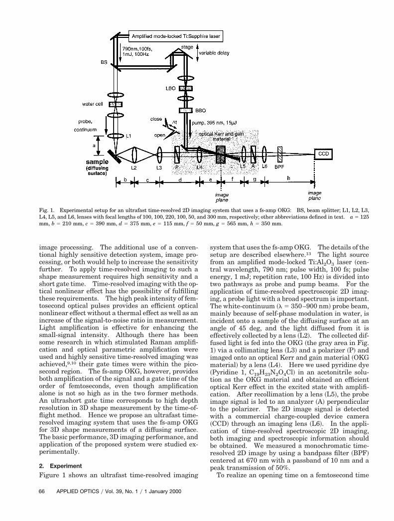
Fig. 5. ~a! Sample consisting of a test chart and a thickness gaugof the fs-amp OKG signal from the stepped part of the sample; ~d!,~B!. The intensity distribution along line ab is also shown. The100 mm in depth.
amplification effect, by slightly shifting the OKGshutter plane from the focal point of the pump beam.The effect of the complicated mode pattern of thepump beam was also relieved by this method. In ourfs-amp OKG setup with an interaction length of 2 mmand a pump beam diameter of 200 mm, the Gaussianprofile does not decrease the image contrast. This isso because the image size of the test pattern is muchsmaller than the diameter of the pump beam in theimage plane in the OKG material. Further investi-gation of these effects on higher spatial resolution isongoing.19
B. Depth Resolution
The positioning accuracy in each time-resolved imagewas 5.9 mm, as determined from the peak positionccuracy ~528 fs! in the temporal behavior of thes-amp OKG signal ~see Fig. 2!. On the other hand,he depth resolution corresponds to the minimumnterval in depth at which it is possible to distinguishhe two images that simultaneously exist along theepth axis. This property would limit performancen the case of multiple layers or image recognitionithout processing. A sample for evaluation ofepth resolution consists of a test chart with a mirrorurface and a thickness gauge ~thickness, 100 mm!ith a rough surface, as shown in Fig. 5~a!, where the
est chart is partly covered by the thickness gauge.
! reference image without the fs-amp OKG; ~c! temporal behaviorme-resolved images of temporal behavior at the two peaks ~A! anddifference between the two peaks is 0.5 ps, which is equivalent to
e; ~b~e! titime
1 January 2000 y Vol. 39, No. 1 y APPLIED OPTICS 69

w~crdswtigaatFacctpstsawctwm
bsi
t
7
The probe beam is incident upon a stepped part of thesample, and then the light diffused from the two sur-faces of the sample is measured. The reference im-age without the fs-amp OKG is shown in Fig. 5~b!,
here the image signal from the thickness gaugeright side! is much smaller than that from the testhart ~left side! because of diffuse reflection on theough surface. The temporal behavior of the lightiffused from the whole surface of the sample ishown in Fig. 5~c!. The depth of the stepped partas obtained from the time difference ~50.5 ps! be-
ween the two peaks @~A! and ~B!# that correspond tomage signals from the test chart and the thicknessauge, respectively; the value agrees well with thectual depth ~5100 mm! in the sample. Figures 5~d!nd 5~e! show time-resolved images at the delayimes of the first peak ~A! and the second peak ~B! inig. 5~c!. The intensity distribution along line ab islso shown relative to each time-resolved image. Byomparing the two time-resolved images we can con-lude that it is possible to distinguish those imageshat have a depth interval of 100 mm without imagerocessing. The depth resolution of 100 mm is con-istent with that for the spatial gate obtained fromhe opening time of the fs-amp OKG. In this mea-urement a transverse resolution better than 125 mmnd a small-signal detection of the rough surfaceere also realized. Moreover, if some image pro-
essing such as a simple subtraction of the series ofime-resolved images were allowed, image separationould be possible within a positioning accuracy of 5.9m.
Fig. 6. ~a! Sample with a stepped diffusing surface; ~b! propaga-ion of the diffused pulse; ~c!, ~d! time-resolved images at times ~A!
and ~B!. The time difference between them is 0.76 ps, which isequivalent to 150 mm in depth. The collection efficiency of thediffused light is 0.1%. Integration of the CCD camera, 0.5 s, isperformed to smooth the image, although the signal intensity issufficient even with one shot of the pulse.
0 APPLIED OPTICS y Vol. 39, No. 1 y 1 January 2000
5. Application
A. Stepped Diffusing Surface
We applied the fs-amp OKG imaging system to shapemeasurement of a stepped diffusing surface coveredwith white paint, as shown in Fig. 6~a!. The collec-tion efficiency of the light diffused from the sample is0.1% in the image plane in the fs-amp OKG. Asshown in Fig. 6~b!, optical pulses, diffused on surfacesof the letter T and its surroundings, travel with atime delay that corresponds to the depth ~5150 mm!etween the two surfaces. A 3D image of thetepped surface is obtained by the time-resolved 2Dmages at times ~A! and ~B! and the time difference
between them. Figures 6~c! and 6~d! show time-resolved images at two times ~delay times of 0 and0.76 ps!. The integration time of the CCD camera isset at 0.5 s, which means that time-resolved images of50 pulses are accumulated, to suppress pulse-to-pulse fluctuation of the spatial intensity distribution
Fig. 7. ~a! Sample with a spherical diffusing surface, ~b! succes-sive differences of the time-resolved images at each incrementaldelay time of 0.67 ps, and ~c! 3D shape of the spherical diffusingsurface. The probe beam is incident at the base of the heart-shaped object. The collection efficiency of the diffused light is0.01%. Integration of the CCD camera, 0.5 s, is performed tosmooth the image, although the signal intensity is sufficient evenwith one shot of the pulse.

it
Tbfcsr0ssAastass
of the image, although the signal intensity is suffi-cient even for one shot of the pulse. A 150-mm depths calculated from the difference ~50.76 ps! betweenimes ~A! and ~B!, in good agreement with the actual
depth of the sample.
B. Spherical Diffusing Surface
Next we demonstrate the shape measurement of aspherical diffusing surface, as shown in Fig. 7~a!.
he probe beam ~diameter, 1 mm! is incident at thease of a heart-shaped object. Because radial dif-use reflection upon a rough spherical surface de-reases the collection efficiency to 0.01%, highlyensitive measurement is required. After five time-esolved images were measured at every delay time of.67 ps, we calculated the differences between twouccessive images. Images of the sample changeduccessively, corresponding to the spherical shape.fter each image was converted into a binary image,s shown in Fig. 7~b!, the 3D shape of the heart-haped object was reconstructed from the delayimes, as shown in Fig. 7~c!. A short opening timend high sensitivity of the fs-amp OKG permit mea-urement of the 3D shape of a spherical diffusingurface with a rather pronounced curvature.
6. Conclusions
We have proposed an ultrafast time-resolved 2D im-aging system that uses a fs-amp OKG for 3D shapemeasurement of a diffusing surface. The salientcharacteristics of its performance are an openingtime of 459 fs and a maximum transmittance of185%, which provided high spatial resolution andhigh sensitivity, respectively, in the shape measure-ment of a diffusing object. The use of another ap-propriate OKG material will improve the basicperformance of the fs-amp OKG.
We evaluated the effect of surface roughness on theopening time of the fs-amp OKG. The opening time,which determines the depth of the spatial gate, isinsensitive to surface roughness Ry in the range 1.3–36.3 mm. However, if we want to apply a narrowerspatial gate to shape measurement, we cannot ne-glect the effect of temporal broadening in an opticalpulse that results from surface roughness. On thecontrary, in such a case the surface roughness of theobject can be obtained from the temporal broadeningof the optical pulse.
The transverse resolution of the proposed time-resolved 2D imaging system is 70 mm ~14.3 line pairsymm! at a contrast of 0.28, where optical nonlineareffects do not cause the quality of the time-resolvedimage to deteriorate. The positioning accuracy inthe depth of each time-resolved image is 5.9 mm.With regard to depth resolution, it is possible to dis-tinguish the two images of a sample with a depthinterval of 100 mm without any image processing.
We have demonstrated two applications of 3D shapemeasurement of the diffusing surface: for steppedsurface and for a spherical surface. It was demon-strated that an ultrafast time-resolved 2D imagingsystem that uses a fs-amp OKG is a powerful tool for
3D shape measurement of diffusing surfaces. More-over, in situ or in process, shape measurements will berealized by use of this method for industrial inspection.
We thank E. Abraham for many insightful discus-sions. This study is supported by a designated re-search project on femtosecond technology of theIndustrial Science and Technology Frontier Program,Agency of Industrial Science and Technology, Minis-try of International Trade and Industry, Japan.
References1. G. Hausler and W. Heckel, “Light sectioning with large depth
and high resolution,” Appl. Opt. 27, 5165–5169 ~1988!.2. V. Srinivasan, H. C. Liu, and M. Halioua, “Automated phase-
measuring profilometry of 3-D diffuse objects,” Appl. Opt. 23,3105–3108 ~1984!.
3. D. M. Meadows, W. O. Johnson, and J. B. Allen, “Generation ofsurface contours by moire patterns,” Appl. Opt. 9, 942–947~1970!.
4. H. Takasaki, “Moire topography,” Appl. Opt. 9, 1467–1472~1970!.
5. B. P. Hildebrand and K. A. Haines, “Multiple-wavelength andmultiple-source holography applied to contour generation,” J.Opt. Soc. Am. 57, 155–162 ~1967!.
6. S. Andersson-Engels, R. Berg, S. Svanberg, and O. Jarlman,“Time-resolved transillumination for medical diagnostics,”Opt. Lett. 15, 1179–1181 ~1990!.
7. J. C. Hebden, R. A. Kruger, and K. S. Wong, “Time resolvedimaging through a highly scattering medium,” Appl. Opt. 30,788–794 ~1991!.
8. N. H. Abramson and K. G. Spears, “Single pulse light-in-flightrecording by holography,” Appl. Opt. 28, 1834–1841 ~1989!.
9. J. A. Moon, R. Mahon, M. D. Duncan, and J. Reintjes, “Three-dimensional reflective image reconstruction through a scatter-ing medium based on time-gated Raman amplification,” Opt.Lett. 19, 1234–1236 ~1994!.
10. F. Devaux and E. Lantz, “Ultrahigh-speed imaging by para-metric image amplification,” Opt. Commun. 118, 25–27 ~1995!.
11. M. A. Duguay and A. T. Mattick, “Ultrahigh-speed photogra-phy of picosecond light pulses and echoes,” Appl. Opt. 10,2162–2170 ~1971!.
12. X. Liang, L. Wang, P. P. Ho, and R. R. Alfano, “Time-resolvedpolarization shadowgrams in turbid media,” Appl. Opt. 36,2984–2989 ~1997!.
13. K. Minoshima, T. Yasui, E. Abraham, H. Matsumoto, G. Jo-nusauskas, and C. Rulliere, “Three-dimensional imaging usinga femtosecond amplifying optical Kerr gate,” Opt. Eng. 38,1758–1762 ~1999!.
14. K. Minoshima, H. Matsumoto, Z. Zhang, and T. Yagi, “Simul-taneous 3-D imaging using chirped ultrashort optical pulses,”Jpn. J. Appl. Phys. 33, L1348–L1351 ~1994!.
15. G. Jonusauskas, R. Gadonas, and C. Rulliere, “Fast opticalKerr gate with slow nonlinearity,” Opt. Commun. 112, 80–84~1994!.
16. G. Jonusauskas, J. Oberle, E. Abraham, and C. Rulliere, “Fastamplifying optical Kerr gate using stimulated emission of or-ganic non-linear dyes,” Opt. Commun. 137, 199–206 ~1997!.
17. K. Minoshima, G. Jonusauskas, T. Yasui, E. Abraham, C. Rul-liere, and H. Matsumoto, “Femtosecond amplifying opticalKerr gate,” submitted to Opt. Commun.
18. M. D. Duncan, R. Mahon, L. T. Tankersley, and J. Reintjes,“Time-gated imaging through scattering media using stimu-lated Raman amplification,” Opt. Lett. 16, 1868–1870 ~1991!.
19. T. Yasui, K. Minoshima, and H. Matsumoto, “Microscopic im-aging using a femtosecond amplifying optical Kerr gate,” sub-mitted to Appl. Opt.
1 January 2000 y Vol. 39, No. 1 y APPLIED OPTICS 71