Embed Size (px)
Citation preview
C H A P T E R 1
Introduct ion
The fabrication of free form sculptured surfaces such as those for airfoils, turbine blades,
automotive components, shoe soles, etc. requires a significant effort toward the design and
manufacturing of the custom-engineered (special) cutting tools correctly. Development of
accurate geometric models of special cutting tools holds a key position to create these
surfaces. Traditionally, the geometry of cutting tools, including customized cutters, has been
defined using the principles of two-dimensional projected geometry. Such definitions are two-
dimensional (2D) in nature and 2D modeling is insufficient to support current analysis,
prototyping and manufacturing technologies as they lack "information completeness". The
growth of curve and surface modeling in the realm of Computer Aided Geometric Design
(CAGD) [38, 85, 109] helps a designer to accurately model the complex geometry of
customized cutting tool surfaces.
Chapter 1. Introduction
2
This chapter develops the background for the present work and discusses the need to
take up this work. It presents a review of available relevant literature. Objectives of the
present work along with methodology adopted to accomplish them are also discussed here.
1.1 Background
With the growth in technology, the expectations from the product have greatly increased and
the demand on product‟s profile has started becoming more and more complex. The need is
for differently shaped products to capture the customers‟ expectations. The commercial
success of a new product is strongly influenced by the highest possible quality and
productivity achieved. This can be achieved only if the product development process can be
realized in a relatively small time period with the best precise solution.
To realize any surface accurately using conventional subtractive machining process,
two most important factors to be properly controlled are: geometry of the cutting tool and the
kinematic structure of the machine tool. The cutting tool geometry along with the relative
motion between the cutting tool and the work piece generates the profile of the cut. Even the
shapes not possible to manufacture earlier are achievable due to increased control of machine
tools by CNC controllers [146]. Thus, the stress is towards generating accurate geometry of
cutting tools. However, for machining special (complex, free-form) surfaces, the development
of special cutting tools, usually occurs through the time consuming trial and error iterations,
caused by limited, principles of projected geometry approaches. The current state-of-affairs
deals with geometric definition of cutters in terms of 2D based orthographic representations
and nomenclature [30, 33, 149]. This 2D based projected geometry approach is tough to
visualize and understand particularly for complex objects. Many times, it leads to
communication gap. A 2D based model cannot be directly used for any technological
application. Precise three-dimensional (3D) geometric models would be immensely beneficial
in reducing the number of experiments required for tool design and machinability evaluation.
1.2 Motivation
Special revolving cutters are very important cutting tools for many manufacturing industries.
Their geometry, dimensional accuracy and performance along with the quality of cutter‟s
cutting surface, directly influence the precision, efficiency and quality of the machined
Chapter 1. Introduction
3
products. In machining special (complex, free-form) surfaces, existing technology basically
depends on 3-axis / 5-axis CNC machine tools using ball end milling or similar cutters [9, 40,
49, 87, 124, 135]. The existing technology of using ball-end milling cutter to generate varied
profiles has its own disadvantages. Custom-engineered special cutting tools are required not
only to machine complex surfaces but also as special toolings for mass manufacturing.
Replacing a number of tools with just one will generate savings in many aspects as well as
lead to quality enhancement, time saving, cost effectiveness, etc. The evolution of custom-
designed products and their fabrication through machining has placed stringent demands on
customized cutters due to existence of freeform and complex surfaces in its geometric profile.
An accurate mathematical model of a customized cutter is important for its geometric
design. Cutting tool manufacturers and advanced users also require more appropriate definition
of cutting tool geometries. Further, as the three dimensional definition is available it will become
a lot easier to design the special cutting tool as per the specified application. A 3D parametric
based geometric model if developed in a generic manner can represent a range of similar cutters.
To create a comprehensive geometric model that could take into account the wide
variety of tool geometry is rather difficult and this may be the primary reason that the
researchers have not been attracted towards modeling them and the field remains largely
unexplored. At present, the geometry of cutting tools is generally expressed in a mathematical
form not suitable for further manipulations. The advancements in the domain of Computer-
Aided Geometric Design (CAGD) allow a designer to directly define the three-dimensional
(3D) parametric models of the cutting tool surfaces [57, 59]. The proposed 3D models of the
customized cutter can further be used for the Finite Element based engineering analysis, stress
analysis, simulation of the cutting process, grinding / manufacturing of the cutter, etc. For this
reason, studies relating to customized cutters (their unified representation scheme, accurate
mathematical 3D model, dedicated cutting tool design software along with downstream
technological usage) are both broad in scope and versatile in application.
1.3 Problem Definition
This works makes an attempt to develop a novel unified representation scheme that can
provide direct 3D generic definitions of custom-engineered (special) cutting tools for (a) their
correct design and fabrication and (b) downstream technological applications. In view of the
Chapter 1. Introduction
4
importance of developing special cutting tools to generate free form complex surfaces and
mass manufacturing, we formally state the problems undertaken in this work as follows:
(i) The geometry of a generic custom engineered cutting tool is to be defined using
geometric modeling approach to develop its three dimensional model. 3D
nomenclature that includes 3D rotational angles and other dimensional parameters is
to be specified for the geometry of cutting tools.
(ii) A cutter design interface is to be developed which may help render the generic
definition of custom-engineered cutting tools directly in any CAD modeling
environment to validate the methodology and provide convenience in downstream
technological applications.
(iii) The generic CAD model of custom-engineered cutting tools acts as a core model and
the family (a variety) of special cutting tools may be generated by suitable
modifications in the parameters of generic cutters. Besides, a few special cutters need
to be developed and their geometry is optimized as per the specific application
1.4 Manufacturing Processes and its Classification
Manufacturing can be simply defined as value addition processes by which raw materials of
low utility and value are converted into high utility and valued products. The process of
manufacturing imparts some functional ability with definite dimensions, forms and finish to
raw materials of inadequate material properties and poor or irregular size, shape and finish.
The core of manufacturing operations is the process responsible for transforming the shape,
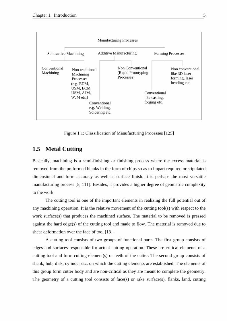
size and finish of the object [42, 58]. Manufacturing processes can be broadly classified in
three major groups, namely, (i) subtractive machining (removal processes), where material is
removed from the blank due to relative movement of a cutting tool over a workpiece; (ii)
additive manufacturing, that deposits material in an empty volume or layer so as to yield the
desired complex configuration and (iii) shaping or forming processes that deform plastically a
given volume or sheet of material. Figure 1.1 shows the different classes of manufacturing
processes. The purpose of all these manufacturing processes is shape realization.
Chapter 1. Introduction
5
Manufacturing Processes
Subtractive Machining Additive Manufacturing Forming Processes
Conventional
MachiningNon-traditional
Machining Processes
(e.g. EDM, USM, ECM, USM, AJM,
WJM etc.)
Conventional
e.g. Welding,
Soldering etc.
Non Conventional
(Rapid Prototyping
Processes)
Conventional
like casting,
forging etc.
Non conventional
like 3D laser
forming, laser
bending etc.
Figure 1.1: Classification of Manufacturing Processes [125]
1.5 Metal Cutting
Basically, machining is a semi-finishing or finishing process where the excess material is
removed from the preformed blanks in the form of chips so as to impart required or stipulated
dimensional and form accuracy as well as surface finish. It is perhaps the most versatile
manufacturing process [5, 111]. Besides, it provides a higher degree of geometric complexity
to the work.
The cutting tool is one of the important elements in realizing the full potential out of
any machining operation. It is the relative movement of the cutting tool(s) with respect to the
work surface(s) that produces the machined surface. The material to be removed is pressed
against the hard edge(s) of the cutting tool and made to flow. The material is removed due to
shear deformation over the face of tool [13].
A cutting tool consists of two groups of functional parts. The first group consists of
edges and surfaces responsible for actual cutting operation. These are critical elements of a
cutting tool and form cutting element(s) or teeth of the cutter. The second group consists of
shank, hub, disk, cylinder etc. on which the cutting elements are established. The elements of
this group form cutter body and are non-critical as they are meant to complete the geometry.
The geometry of a cutting tool consists of face(s) or rake surface(s), flanks, land, cutting
Chapter 1. Introduction
6
edges and the corner(s) or nose [42, 149]. Face is the surface of the cutting tool along which
the chip flows out, while flanks are the surfaces facing the workpiece. The land is that part of
the back of the tooth adjacent to the cutting edge which is relieved to avoid interference
between itself and the surface being machined. The cutting edge is the intersection of the face
of the tooth with the leading edge of the land. Based on the geometry of cutting elements, the
basic cutting tools are of single-point or multi-point design, although they may differ in
appearance and in their methods of application.
1.5.1 Single-Point Cutting Tools
A single-point cutting tool refers to tool for turning, shaping, planing, boring etc., that has one
shank (or body) and one cutting element in the form of a cutting edge at one end [88]. This
cutting edge is often designed to be at one end of a solid piece of steel, either formed or in the
form of an insert, held to the body of the tool by brazing, welding or mechanical means [61].
They are commonly used in lathes, shapers, planers and similar machine tools. During
machining a single-point cutting tool is provided translatory motion while the job is rotated or
translated.
1.5.2 Multi-Point Cutting Tools
A tool with a series of two or more cutting elements / edges (points) on a common body is
known as multi-point cutting tool [88, 111]. These include double (two) point cutters: e.g.,
drills and multipoint (more than two) cutters: e.g., milling cutters, broaching tools, hobs, gear
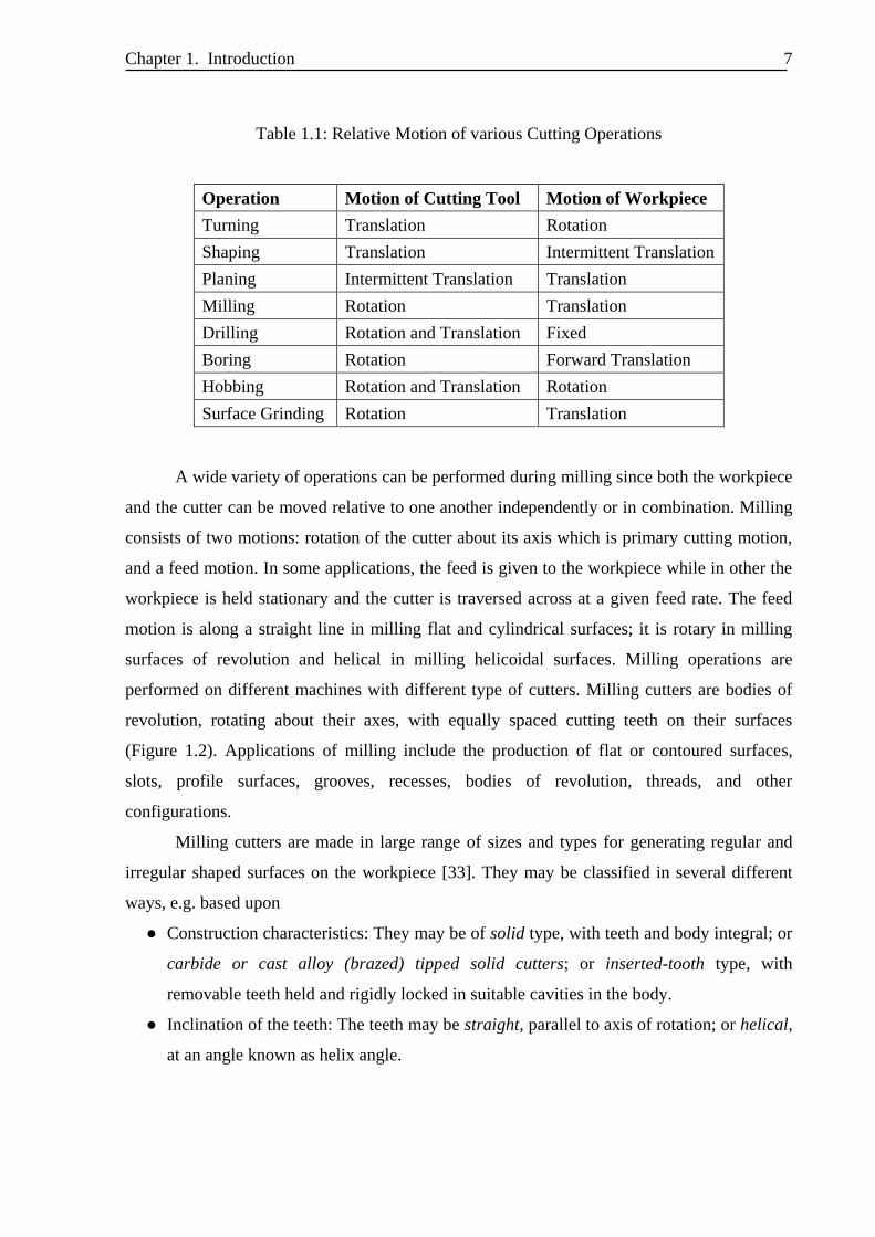
shaping cutters, etc. The majority of multi-point cutting tools are provided rotary motion for
shape realization as shown in Table 1.1 [13]. The common machining operations associated
with multi-point tools - milling, drilling - are introduced in the following subsections.
Milling
Milling is a subtractive shape realization process that removes a predetermined amount of
material from the work piece with the cutting tool rotating at a comparatively high speed. The
cutting tool used for the purpose has multiple cutting teeth. The characteristic feature of the
milling process is that each milling cutter tooth removes its share of the stock in the form of
small individual chips during each revolution from the advancing work [30, 33, 149].
Chapter 1. Introduction
7
Table 1.1: Relative Motion of various Cutting Operations
Operation Motion of Cutting Tool Motion of Workpiece
Turning Translation Rotation
Shaping Translation Intermittent Translation
Planing Intermittent Translation Translation
Milling Rotation Translation
Drilling Rotation and Translation Fixed
Boring Rotation Forward Translation
Hobbing Rotation and Translation Rotation
Surface Grinding Rotation Translation
A wide variety of operations can be performed during milling since both the workpiece
and the cutter can be moved relative to one another independently or in combination. Milling
consists of two motions: rotation of the cutter about its axis which is primary cutting motion,
and a feed motion. In some applications, the feed is given to the workpiece while in other the
workpiece is held stationary and the cutter is traversed across at a given feed rate. The feed
motion is along a straight line in milling flat and cylindrical surfaces; it is rotary in milling
surfaces of revolution and helical in milling helicoidal surfaces. Milling operations are
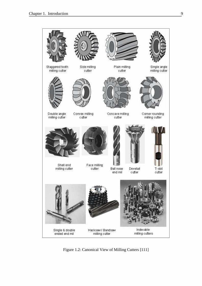
performed on different machines with different type of cutters. Milling cutters are bodies of
revolution, rotating about their axes, with equally spaced cutting teeth on their surfaces
(Figure 1.2). Applications of milling include the production of flat or contoured surfaces,
slots, profile surfaces, grooves, recesses, bodies of revolution, threads, and other
configurations.
Milling cutters are made in large range of sizes and types for generating regular and
irregular shaped surfaces on the workpiece [33]. They may be classified in several different
ways, e.g. based upon
● Construction characteristics: They may be of solid type, with teeth and body integral; or
carbide or cast alloy (brazed) tipped solid cutters; or inserted-tooth type, with
removable teeth held and rigidly locked in suitable cavities in the body.
● Inclination of the teeth: The teeth may be straight, parallel to axis of rotation; or helical,
at an angle known as helix angle.
Chapter 1. Introduction
8
● Relief of the teeth: The teeth may be profile-relieved, when the relief surface is
comparatively simple flat or helical and the relief is obtained by grinding a narrow land
back of the cutting edge, viz. slab or plain milling cutters, side milling cutters, slotting
cutters, end milling cutters, face milling cutters, etc; or form-relieved, when the relief
surface is curved and the relief is obtained by grinding the faces of the teeth, viz. form
cutters, gear milling cutters, spline shaft cutters, thread milling cutters etc.
● Method of mounting: The milling cutters can be made arbor mounted, with a center
hole for mounting on an arbor; or shank type; or spindle mounted, with the back
recessed for bolting directly on the spindle nose.
● Hand of rotation and hand of helix: Milling cutters may be made for either right or left
hand of rotation, and with either right or left hand helix.
● Purpose or use of the cutter: Milling cutters can be of type T-slot cutter, Woodruff key
seat cutter, Gear or Thread milling cutter.
In the broader perspective, milling cutters may fall into the following two categories:
● Standard Milling Cutters: These conform to dimensions approved by the international
standards bodies (e.g. ISO, ASA, DIN, BS). The dimensional standards, relating chiefly
to cutter diameter and width, size of center hole, width and depth of keyway, etc., have
been adopted by cutter manufacturers.
● Special Milling Cutters: These are designed for work on special jobs. They may or may
not have standard dimensions, and do not conform to any generally accepted standard.
They are normally designed to combine several milling operations in one, and may be
used for milling regular or irregular surfaces.
Drilling
The operation where the tool is rotated and fed along its axis of rotation while the work piece
remains stationary is called drilling [33, 88]. The most common type of drilling is the operation with
a twist drill to generate a hole. A twist drill with a shank has two (or more) cutting edges, each
responsible for removal of work material. The tool used for drilling is the drill bit. The drill bit is a
multipoint, end cutting tool. It cuts by applying pressure and rotation to the work piece, which forms
chips at the cutting edge. There are a variety of drill styles that each serves a different purpose.
Chapter 1. Introduction
9
Figure 1.2: Canonical View of Milling Cutters [111]
Chapter 1. Introduction
10
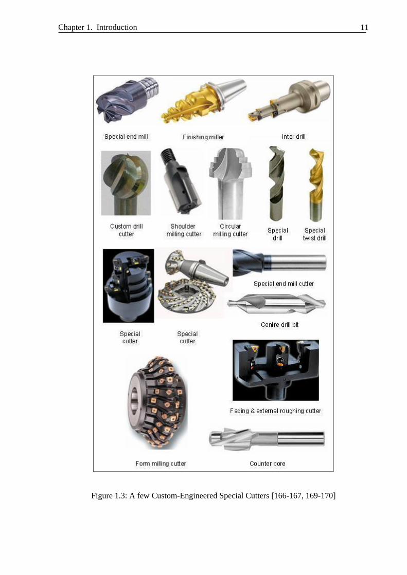
1.5.3 Custom-Engineered Cutting Tools
A customized form tool is a cutting tool having one or more cutting edges with a defined
profile or contour that will be reproduced as the desired form on the work surface (Figure
1.3). Basically, the geometry of cutting elements / edges (points) of form tools can be of
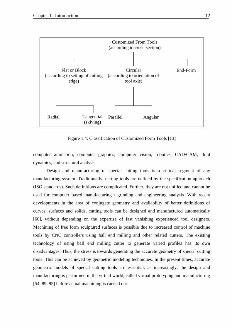
single point or multipoint design. Besides, form tools may be classified according to type of
cross-section, which may be (a) flat form tools, (b) circular tools and (c) end-form tools
(Figure 1.4) [13]. Flat or block tools are further classified according to setting of the tool with
respect to work piece like radial-fed or tangential-fed type. Further form tools are also
classified with respect to orientation of tool axis in relation to work piece axis.
1.6 Need of Geometric Modeling for the Design of Custom-
Engineered Cutting Tools
Geometric modeling is defined as generation of computer-compatible mathematical definition
of geometry / shape of an object [38, 85]. In geometric modeling, we define a shape by a set
of mathematical statements and logical relations satisfying a set of axioms. These axioms we
interpret as true statements about the model, and the consequent general properties of the
model we analyze and evaluate as representative of the modeled object itself. Geometric
modeling is the process of creating these statements and relationships. Besides, geometric
modeling is the construction or use of geometric models. Geometric models can be built for
objects of any dimension in any geometric space. Basically, 2D, 2½D and 3D geometric
models are extensively used in computer graphics. 2D models are important in computer
typography and technical drawing. 2½D and 3D models are central to computer-aided design
and manufacturing, and many applied technical fields such as geology, medical image
processing, etc.
Computer-aided geometric design (curve and surface modeling) (CAGD) and solid
modeling are the branches of geometric modeling. Computer-aided geometric design (CAGD)
applies the mathematics of curves and surfaces to modeling, primarily using the parametric
equations of differential geometry [109]. Solid modeling allows us to combine simple shapes
to create complex solid models. Solid modeling has its mathematical foundations in topology,
algebraic geometry and Boolean algebra. Geometric modeling has applications in the fields of
Chapter 1. Introduction
11
Figure 1.3: A few Custom-Engineered Special Cutters [166-167, 169-170]
Chapter 1. Introduction
12
Figure 1.4: Classification of Customized Form Tools [13]
computer animation, computer graphics, computer vision, robotics, CAD/CAM, fluid
dynamics, and structural analysis.
Design and manufacturing of special cutting tools is a critical segment of any
manufacturing system. Traditionally, cutting tools are defined by the specification approach
(ISO standards). Such definitions are complicated. Further, they are not unified and cannot be
used for computer based manufacturing / grinding and engineering analysis. With recent
developments in the area of conjugate geometry and availability of better definitions of
curves, surfaces and solids, cutting tools can be designed and manufactured automatically
[60], without depending on the expertise of fast vanishing experienced tool designers.
Machining of free form sculptured surfaces is possible due to increased control of machine
tools by CNC controllers using ball end milling and other related cutters. The existing
technology of using ball end milling cutter to generate varied profiles has its own
disadvantages. Thus, the stress is towards generating the accurate geometry of special cutting
tools. This can be achieved by geometric modeling techniques. In the present times, accurate
geometric models of special cutting tools are essential, as increasingly, the design and
manufacturing is performed in the virtual world, called virtual prototyping and manufacturing
[54, 89, 95] before actual machining is carried out.
Flat or Block
(according to setting of cutting
edge)
Customized From Tools
(according to cross-section)
Circular
(according to orientation of
tool axis)
End-Form
Radial Parallel Angular Tangential
(skiving)
Chapter 1. Introduction
13
Recent developments in the area of CAGD have led to various mathematical
definitions of analytic and synthetic uniparametric curves and biparametric surfaces [39, 85,
109, 157]. These biparametric surfaces can correctly model any free formed sculptured
surface. This has led to tremendous growth in the development of CAD models of complex
shaped objects. However, the area of application is still mainly confined to automobile and
aerospace sectors and any work that is undertaken in the direction of developments of CAD
models of cutting tools is not known. The need of geometric modeling of the custom-
engineered (special) cutting tools can be further stressed due to
(i) Cutting tool surfaces are complex, hence their proper definitions are required.
(ii) Cutting tool standards need upgradation as they depend on 2D definitions.
(iii) Tool and cutter grinders are having a focused shift from manual to computer
controlled.
(iv) Cutting tools are increasingly manufactured and sharpened by CNC machine tools
and in CNC machines, programming is crucial, particularly of free form surfaces.
Convenience and accuracy of CNC programming improves with the CAD definition
of the object.
(v) Though there exist many powerful CAD softwares today, but a dedicated cutting tool
CAD software is yet to be designed.
(vi) None of the existing CAD softwares contain any cutting tool design module.
(vii) Geometric modeling enables the designer to generate centralized and integrated
database. Such a database for special cutting tools can convey design information for
a range of downstream engineering and manufacturing applications.
(viii) A generic CAD model of the available custom-engineered cutting tools acts as a core
model and new special cutting tools can be generated by modifying its parameters
and activities like rendering, simulation, analysis, manufacturing etc. can be
performed using this core model.
1.7 Review of Literature
The prediction of cutting forces in machining along with mechanics and dynamics of cutting
tools are the areas that have captured major attention of researchers in the field of
manufacturing. Even in these areas also, the stress is towards milling processes and milling
Chapter 1. Introduction
14
cutters due to their wide spread usage. With more and more components having sculptured
surfaces, CNC machining is in greater demand. These surfaces are normally generated on
CNC machines by ball end mills and this has made the researchers' focus on developing
cutting force models for end milling. These models approximate the geometry of cutting tools
by presenting them in two-dimensional space. The end geometry of the ball and flat end mills
is modeled by dividing cutting edges into infinitesimal elements is proposed by Abrari and
Elbestawi [1], Zheng et al. [161], Li et al. [72], Zhang et al. [160], Wang et al. [142]. Wan and
Zhang [138] have done a systematic study on cutting force modeling methods in peripheral
end milling in the presence of cutter runout. The analytical representation of helical flute
geometry is proposed by Lee and Altintas [68], Gradisek et al. [41], Yucesan and Altintas
[156], while cutting force prediction model is combined with models for cutter deflection and
machining accuracy to study surface errors for end milling by Liu et al. [78-79], Ratchev et al.
[106] and Xu et al. [152]. In all these approaches, mechanistic or analytical models for
predicting cutting forces are developed based on the input data of work piece material
properties, tool geometry and cutting conditions. They have shown that the instantaneous
cutting force model has better prediction ability than the model with constant cutting force
coefficients.
The work in the area of modeling the mechanics and dynamics of milling cutters is to
predict factors like chip thickness, cutting force, vibration, torque, power, surface finish etc.
Smith and Tlusty [120] have reviewed frequently used models of force and deflection
computation for milling process and highlighted their validity, applications and limitations
while mechanics and dynamics of general milling cutters, especially helical end mills and
inserted cutters has been reported by Engin & Altintas [36-37]. Here, the end mill geometry is
modeled by helical flutes wrapped around a parametric envelope and the chip thickness at
each cutting point on helical flute is evaluated by using the true kinematics of milling
including the structural vibrations of both cutter and work piece. Chiou et al. [25] has
demonstrated an instantaneous shear plane based computational model to predict the cutting
force components for end milling. A comprehensive integrated static and dynamic cutting
model for ball end milling processes has been presented by Altintas and Lee [2-3]. Lee et al.
[69] have designed a face milling cutter and developed a cutting model to improve its
dynamic characteristics. Chang [18] has also presented a new predictive force model and
proposed high efficiency face milling tools. Besides this, a simplified and efficient calibration
Chapter 1. Introduction
15
of a mechanistic cutting force model for ball-end milling is developed for a wide range of
cutting conditions by Azeem et al. [8], for sculptured surfaces by Sun et al. [124] while a
novel cutting force modeling method based on instantaneous cutting force and instantaneous
uncut chip thickness measurement for cylindrical end mill is proposed by Wan et al. [139]. A
review of the above literatures shows the calibration procedure of instantaneous cutting force
coefficients during end milling from both the theoretical analysis and the numerical
simulation. Also, it is essential to further improve the prediction accuracy of cutting forces
and algorithms to concrete implementations for sculptured surface machining.
Another domain of interest in manufacturing research is the design of milling cutters.
Vickers and Quan [135] have presented a comparison of insert-based flat end mills and solid
ball-end mills in machining low curvature surfaces. Chen and Lin [20] have developed design
and manufacturing models for ball-end cutters based on envelope theory while Kim and Ko
[62] has discussed the design and manufacturing technology for end mills. Chen et al. [21-22]
has presented manufacturing models to produce concave cone end milling cutters. Work on
cutters other than end mills include geometric modeling of single point cutting tools by
Rajpathak [103], design of cutters to manufacture helicoidal surfaces by Karunakaran and
Dhande [59], design of hob cutters for generating the multi-cutting angles (radial rake angle,
relief angle, and clearance angle) of helical cutting tools is proposed by Liu and Chang [77]
and design and manufacturing of hob for machining of precision involute gear by Radzevich
[99, 101]. A universal hypoid generator mathematical model for face hobbing spiral bevel and
hypoid gears has been developed by Shih et al. [119]. Vasilis et al. [133] has proposed
simulation of gear hobbing through three-dimensional kinematics modeling. Author has
described an effective and factual simulation of gear hobbing, based on virtual kinematics of
solid models representing the cutting tool and the work gear. CAD-based simulation of the
hobbing process for the manufacturing of spur and helical gears is done by Dimitriou and
Antoniadis [32]. Carlsson and Stjernsoft [15] have calculated the geometrical shape of tool-
work interface for rotary tools. Very recently, Shi and Liu [117] have discussed the actual
geometry of the cutting tool involved in machining based on their three-dimensional
geometric models. The above researchers have emphasized more on manufacturing models,
understanding the machining mechanism based on the three-dimensional geometry of the
cutting tool. The resulting 3D data allows the effective utilization for further research such as
Chapter 1. Introduction
16
prediction of the cutting forces, tool stresses, and wear development as well as the
optimization of the cutting tool design process.
Simulation of milling processes is also a major area of research in manufacturing. The
problem of defining the geometry of a machined surface is essentially a problem of defining
the boundary of the swept volume of the cutter. Spence and Altintas [122] have discussed a
constructive solid geometry (CSG) based system to simulate the milling process and assist in
online monitoring and control tasks. Mounayri [86] have modeled part as boundary
representation (B-rep) model and tool cutting edges as cubic Bezier curves to evaluate cutter
swept volume, material removed and tool-part immersion geometry. An approach to integrate
solid modeling with milling process simulation and its applications in machining is shown by
Spence et al. [123]. Imani and Elbestawi [50] have developed precise B-rep model of the
cutter swept volume to update part being machined for each NC block, evaluate instantaneous
chip geometry and model feed marks and scallops on the machined surface. 5-axis sculptured
surface machining is simulated using discrete geometric models of the tool and work piece to
determine the tool contact area and a discrete mechanistic model to estimate the cutting forces
is presented by Fussell et al. [40]. Simulation of flank milling processes has been discussed by
Bedi et al. [11] as well as Larue and Altintas [67]. Also, Li et al. [70] has suggested an easier
way to design the surface for flank milling, especially when the guiding curves are non-
rational B-spline curves (NUBS). A solid model-based milling process simulation and
optimization system integrated with CAD/CAM is developed for 3-axis end milling by Li et
al. [73] while modelling of tooth trajectory and process geometry in peripheral milling of
curved surfaces is presented by Rao and Rao [105]. These researches contribute towards
various surface design methods used to design the surface for flank milling effectively
Geometry of the twist drills has been studied by Armarego and Kang [6], Ehmann
[34], Ekambaram and Malkin [35], Kaldor et al., [56-57], Sheth and Malkin [115], Ko [63],
Shatla and Altan [113], Zhang et al. [159], Lacalle et al. [65]. However, the work is not in the
direction of development of generalized CAD (Surface/Solid) model for the twist drills. These
works are to evaluate the shape of drill profile for a given milling cutter (or grinding wheel) or
identification of geometry of a milling cutter (or grinding wheel) used to generate a given
twist drill. The resulting data and information have to be fed to an experienced tool engineer
to manufacture or ground the twist drill. Other work on drills includes drill analyses to modify
its designs by Bhattacharyya et al. [14], Shi et al. [116], Lin et al. [74], Ren and Ni [108], Paul
Chapter 1. Introduction
17
et al. [92], Zhang et al. [158], Vijayaraghavan and Dornfeld [136] and mathematical modeling
for multiflute drill designs by Wang et al. [140], Hsieh and Lin [43], Hsieh [44].
Optimizing the design of the milling cutter based on finite element based engineering
analysis is done by Jha and Hornik [52], Shih [118], Tawfiq and Shahab [130]. Also,
simulation of metal cutting process using finite element method has been studied by Shet and
Deng [114], Ozel and Altan [90], Lo [81], Ozel and Zeren [91]. To improve the accuracy of
the model of milling operations, three-dimensional finite element modeling is performed by
Pittala and Monno [94] for the insert based face milling and by Soo et al. [121] for ball nose
end milling.
Considerable work has been done by the researchers to study the conventional single
point [45, 127, 134] and multi-point cutting tools. For producing the sculptured complex
surfaces, we are heavily dependent on CNC machine tools using ball end cutters. Basically,
generation of sculptured free form surfaces using NC / CNC machines has been worked by
Hwang and Chang [49], Warkentin et al. [144], Choy and Chan [27], Wei and Lin [146],
Naserian et al. [87], Ren et al. [107]. Recently, Yau and Tsou [153] has presented the use of
adaptive voxel data structure in conjunction with the modeling of a universal cutter for the
development of an efficient and reliable multi-axis simulation procedure. Very few custom-
engineered cutting tools have drawn the attention of the research fraternity although they are
good candidates for manufacturing free form special surfaces as well as for mass
manufacturing. The reasons for this could be possibilities of various designs of customized
cutters, their complex geometries and difficulties in defining these complex, free form
surfaces mathematically. To create a comprehensive geometric model that could take into
account this wide variety of complex tool geometry is rather difficult and this could be
primary reason that the researchers have not been attracted towards modeling them and the
field remains largely unexplored. In fact, Mendoza et al. [83] has developed a new milling
cutter for Aluminium honeycomb structures used in the air space industries. Kuo and Wu [64]
have presented a work in the direction of geometric solution for the roller nest mill cutter.
Manufacturing models of various customized end milling cutters has been discussed by Wang
et al. [143], Chen et al. [19], Chen et al. [23], Hsieh [48], Pham and Ko [93]. Hsieh and Tsai
[47] have presented the geometric modeling and grinder design for toroid-cone shaped cutters.
Radzevich [98-100] has suggested a novel method for mathematical modeling of an optimized
form-cutting tool for machining a given sculptured surface based on R-mapping. The work in
Chapter 1. Introduction
18
the direction of development of geometry design of a form milling cutter for precisely
obtaining the complex freeform surfaces is done by Wang et al. [141]. Also, work related to
the design of a plunge shaving cutter is presented by Radzevich [102] and Liu et al. [76] while
a novel hob cutter design is developed by Hsieh et al. [46] for the manufacture of spur-typed
cutters. If 3D geometric definitions of customized cutting tools are available then it will be of
immense benefit to the manufacturing world due to ease in simulation of a machining process
before actual machining, as well as numerous direct applications.
Recent developments in the field of geometric modeling now provide designers an
elegant and precise approach of specifying the geometry of complex shaped objects [85],
Choi [26], Farin [38], Rogers and Adams [109], Zeid [157]. A method for computer-aided
design for machining of sculptured surfaces taking the complex machined surface as the
nonuniform rational B-spline (NURBS) surface has been discussed by Barari et al. [9], while
Tandon et al. [128-129] have discussed the modeling of side mills and twist drills in terms of
biparametric surface patches. It is found that the conjugate geometry approach can be
extended to machining and together with computational models and symbolic algorithms, it
can conveniently model different manufacturing processes (Dhande et al. [31], Voruganti et
al. [137]). Some recent work in the associated areas that motivated the present work includes,
the work by Barone [10], where B-spline curve fitting and sweep surface generation are used
for the geometric design of involute gears; an approach to optimize macro-level tool geometry
in machining by Kaldor and Venuvinod [55]; about orthogonal parameterization of part and
tool surface for transformation of coordinate systems by Radzevich and Goodman [97];
parametric surface rendering mentioning the advantages offered by parametric surface for
object modeling by Li [71]; the use of computer-aided design tools in the conception and
realization of geometrical sculptures as described by Sequin [112]; task automation for
modelling solids with Catia V5 by Cidoncha et al. [28]; computer simulation methodology of
modelling tooth flanks of cylindrical gears by Michalski and Skoczylas [84] and the
methodology proposed by Pu and Liu [96] for the geometric modeling of cylindrical helix end
mill with NURBS solid model which is different from the traditional three-dimensional
model. The above mentioned research work shows a way to effectively describe complicated
geometric shapes of cutter flanks utilizing computer-aided geometric design approaches.
Research in the area of feature modeling of sculptured objects has addressed the need of
unified geometric models (Au and Yuen [7], Cavendish [16-17], Kagan et al. [53], Roller
Chapter 1. Introduction
19
[110], Tonshoff [132], Ye et al. [154], Liu [80], Yeh and Su [155], Langerak and Vergeest
[66]).
Modeling and simulation of machining process is an approach to realize high quality
machined parts. The shape of the cutting tool is one of the key factors to affect the machining
accuracy and dynamic stability. It is difficult to model the exact three-dimensional shape of a
special cutting tool since the cutter geometry is very complicated. For modeling any custom-
made cutting tools, there are no unified representation schemes that can provide direct 3D
models for downstream technological applications. In general, the cutting tools are
represented by a simplified model [36-37, 86]. These mathematical models are hardly more
than a visual and complete model. The proposed approach of modeling surface patches
provides unified models of a range of custom-engineered (special) cutting tools. We aim at
producing a system of equations in their parametric form to develop an accurate 3D surface
based model of customized cutters.
1.8 Objectives and Scope of the Present Work
The primary goals of this work are
(a) To develop three-dimensional definitions of the existing custom-engineered cutting
tools (form, milling, special purpose, etc.) for machining free form / special surfaces
as well as for mass manufacturing, and to define in detail its geometric modeling and
(b) To design and manufacture new custom-engineered cutting tools for some special
applications (where the surface profile to be generated is already known).
Besides, we would also like to
(i) Develop surface based geometric models of custom-engineered cutting tools in terms
of their surface patches using the evolved 3D rotational angles and other dimensional
parameters.
(ii) Establish a set of 3D nomenclature for specifying the geometry of the special cutting
tools.
(iii) Interface properly the new generic definition of custom-engineered cutting tools with
advanced modeling software for customized applications.
(iv) Verify the surface model based definition of the cutting tools using point cloud data
(reverse engineering methodology) for the existing tools.
Chapter 1. Introduction
20
(v) Perform detailed finite element analysis of the model and if need be, modify the
design of the cutting tool.
(vi) Establish relationship between proposed three-dimensional nomenclatures and
traditional two-dimensional projected geometry based nomenclatures (if available).
(vii) Establish generic definition and to develop a unified definition of custom-engineered
special cutting tool that may be used for numerous downstream engineering and
manufacturing applications.
The scope of the present work includes:
(i) Establishment of generic CAD model (mathematical definition) of cutting tool
surfaces.
(ii) Establishment of a new CAGD based 3D nomenclature to define the geometry of
customized cutting tools.
(iii) Development of a “Cutter design module” that acts as an interface for modeling
complex tools as well as mechanical components in existing commercial CAD
packages.
(iv) Demonstration of the effectiveness of the new definition.
1.9 Flow of Work
The approach adopted to accomplish the present work is by
(i) Critically reviewing and classifying the custom-engineered (special) cutting tools on
the basis of their geometric complexity and application.
(ii) Selecting particular application areas like engineering industry, leather industry,
plastic industry, wood carving / shaping industry, etc. and designing the custom-
engineered cutting tool for their engineering applications
(iii) Identifying critical or functional and non-critical elements of the cutting tool.
(iv) Developing appropriate mathematical biparametric definitions for unbounded
functional surfaces of the cutting tool.
(v) Defining the parameterized geometry of bounded curved surfaces by establishing the
limits of parameters of the unbounded surfaces, understanding the topology of cutter
and ensuring continuity conditions.
Chapter 1. Introduction
21
(vi) Specifying the cutting tool geometry in terms of 3D nomenclature (3D rotational
angles ii , and i ) and various other dimensional parameters, collectively termed
as geometric parameters. In 3D nomenclature, angles ii , and i are the angles of
rotation of surface patch „i ‟ about X, Y, Z axis respectively, where positive
rotation directions about the coordinate axes are counter clock wise, when looking
toward the origin from a positive coordinate position on each axis.
(vii) Modeling the transitional surfaces of the surface patches. A transitional surface
forms a smooth localized transition between neighboring surfaces at their edge of
intersection.
(viii) Developing an interface (Cutter design module) to pull the generic definition of
custom-engineered cutting tools directly in a CAD modeling environment for further
validation.
(ix) Selecting the representative custom-engineered cutting tools and reverse engineer
them to collect point cloud data to compare surface features with that of actual
cutting tools.
(x) Performing detailed finite element analysis of the selected cutter
(xi) Redesigning and optimizing the geometry of the cutter as per the feedback of
analysis.
(xii) Manufacturing a few selected special cutting tools for technology demonstration.
(xiii) Demonstrating the utility of the new convention through direct engineering
applications on the proposed model.
1.10 Advantages of the Proposed Methodology
The advantages of an accurate 3D definition of a complex object like a cutting tool include:
● Virtual and Physical Prototyping for verifying the geometry and topology of the
object.
● Implementation of the NURBS curve and sweep surfaces for the shape design of the
cutting edge / surfaces for the customized cutter gives more control for cutting edge
profile modification and generation of varied surface profiles.
Chapter 1. Introduction
22
● The cutting tool design modeler developed in the course of this work can also act as a
module of any existing commercial CAD packages.
● Simulation of CNC machining or grinding process before actual cutting operation can
be performed.
● Geometric analysis of tool wear through Reverse Engineering (Surface-point cloud
comparison) can be done easily and accurately.
● Detailed finite element analysis can be performed on the detailed 3D CAD model of
the cutter and one can have more precise results for stress, strain, displacements, etc.
during machining.
1.11 The Layout of the Thesis
A brief overview of the work carried out in the thesis and organization of the same are
summarized below.
Chapter 1 presents the background, motivation and problem definition of the thesis
work. Here, brief information is given for the manufacturing processes, cutting tools available
and the need of geometric modeling in the design of special cutters. It is followed with a brief
review of the relevant literature. This chapter concludes with the objectives and scope of the
work along with the methodology adopted to accomplish the work.
Geometric modeling of a flat end mill is presented in Chapter 2. The chapter develops
detailed surface models of the flat end mill and a modeling algorithm is proposed here.
Further, the implementation of the algorithm is performed in OpenGL and CATIA V5
environment for the validation of the methodology. One of the downstream technological
applications of the 3D model in terms of finite element based engineering analysis of the
cutter is also presented and results are compared.
Chapters 3 deal with one of the existing insert based custom-engineered form milling
(CEFM) cutter. In this chapter, a unified geometric model of the insert and the cutter body of
the CEFM cutter is developed. The approach is established by rendering the 3D cutter model,
through Cutter design interface (developed during the work). The accuracy of the proposed
model in also verified through Reverse Engineering (RE) technique. The design
improvements and redesigning of the special shaped milling cutters for a few applications are
also discussed here.
Chapter 1. Introduction
23
Chapter 4 deals with a novel design of a generic multi-profile form milling (MPFM)
cutter, developed for machining multiple sculptured surfaces. The work develops a 3D based
representation scheme of generic MPFM cutters in terms of NURBS curves along with 1-rail
and 2-rail sweep surfaces. Shape design of a generic tooth and the cutter body is discussed in
detail. The chapter also presents the modeling algorithm and the implementation of the
methodology.
Chapter 5 presents the development of a novel multi-radius form milling (MRFM) cutter.
Force and torque measurement is performed during cutting simulation for the novel MRFM cutter
and the traditional concave milling cutter and the results are compared. The chapter concludes
with an example of finite element analysis of the novel cutter with the actual cutting conditions.
Chapter 6 summarizes the significant findings of the work performed, outline the
current limitations raised by the proposed methodology as well as provide some
recommendations for future work that would further enhance the unified representation
scheme along with design methodology and modeling of various custom-engineered (special)
cutters that dominate mechanical machining industries.