Embed Size (px)
Citation preview
Threat Modeling in Embedded Systems
Anthony Hadding
Instructor: Dr. J. Zalewski
Florida Gulf Coast University
Ft. Myers, Florida
Summer 2012

1 Introduction
1.1 Threat Modeling
Threat modeling is a somewhat generic term referring to the process of analyzing a
software system for vulnerabilities, by examining the potential targets and sources of attack in
the system. Though the approaches differ, and some authors regard threat modeling as an
attacker-centric activity, some authors claim that it is possible to perform threat modeling from a
defensive perspective, and other authors have even broader views, the basis of threat modeling
lies in decomposing the system into its component parts, typically creating a data flow diagram
(DFD) to model the interaction of these parts, at various levels of complexity. [1][2][3] This
introduction will only discuss DFDs.
After creating the diagram, the next step is to examine this diagram for possible targets of
malicious users; such targets are sometimes referred to as "threats".[1] At this point, individual
threats are classified categorically according to some criteria and the nature of the threats. In the
next stage, analysts devise strategies for realizing the threats discovered from the data flow
diagram, in terms of the actions an attacker would have to take to mount a successful attack. A
tool called an "attack tree" is employed for this purpose, and it serves to illustrate at a glance the
required steps to enact an attack as well as the complexity inherent in and feasibility of such an
attack.
After attack trees have been generated, it is necessary to evaluate all known threats in
terms of the overall risk they pose to the system. Threats are typically analyzed to determine their
likelihood of exploitation and potential damage in case of exploitation, but more formal
evaluation and ranking systems, such as DREAD exist. [1] After this risk analysis has been
performed, the developers must decide how to respond to the risk posed by each threat.
Possible options include, but are not limited to, accepting the risk by choosing to take no
action in regards to a threat, removing the risk completely by removing an associated feature,
and mitigating the risk by applying various threat-mitigating techniques, such as authentication,
resource restriction, etc. [1][2] If the software system is still early in development, the decisions
made in this stage may be used to generate specific security requirements for a requirements
specification. [2] Otherwise, the decisions may be used to choose how to maintain a currently-
existing system, as the threat modeling process is equally applicable to existing and non-existing
systems.

One application-oriented threat modeling process, described in [1], breaks the above
outline into specific stages. The first is to decompose the application into key components for
analysis. As mentioned above, a data flow diagram is used for this purpose. Developers then
determine and classify threats to the system according to their STRIDE (spoofing, tampering,
repudiation, information disclosure, denial of service, elevation of privilege) category. Attack
trees (referred to as "threat trees" in [1]) are then generated and used to evaluate and rank the
threats by decreasing risk, using their DREAD (damage potential, reproducibility, exploitability,
affected users, discoverability) system. Developers then choose how to deal with the threats,
techniques to deal with the threats chosen for mitigation, and technologies to implement the
chosen techniques. [1]
1.2 System Decomposition: Data Flow Diagrams
The first step of the threat modeling process, is to decompose the system into a form that
is easily comprehensible by security analysts and developers. While data flow diagrams are not
an explicitly necessary tool for this stage of analysis, and some authors have found a network
model more appropriate for particularly large and complex networked systems [2], data flow
diagrams will be the primary tool described in this section, due to their ease of use and
comprehension.
To be included: data flow diagram explanation, example DFDs showing a system decomposed to
various levels
1.3 Threat Analysis: Attack Trees
After a system has been decomposed into its component parts and threat targets have
been recognized, the next step is to analyze those targets for possible methods of attack. This
stage is more difficult, as it relies on the analyst having enough security knowledge and/or
experience to recognize possible methods of attacking the system, though methods of making
known attacks available to less-knowledgeable developers are implemented in existing tools and
continue to be investigated. [4][8] These methods may then be documented using text outlines or
threat trees to display the necessary and sufficient sequences of steps taken to realize them. [1]
Before continuing, it is necessary to define the terms threat, vulnerability, and attack.
Michael Howard and David LeBlanc offered the following definitions: [1]

Threat - "[...] a potential event that will have an unwelcome consequence if it becomes and
attack."
Vulnerability - "[...] a weakness in a system, such as a coding bug or a design flaw."
Attack - An event that occurs when an attacker has a reason to threaten a system asset.
Figure 1 – An Attack Tree for an Attacker to Eavesdrop on Communication Over a Simple CAN
Figure 1 shows an attack tree (also called "threat tree") for an attacker to eavesdrop on
communication between two users of the control and Hyper Terminal nodes of a CAN bus, as
shown in Figure 2. Rectangular nodes are individual goals of an attacker, needed to realize a
higher-level goal. All rectangular nodes in this diagram represent "OR" conditions, where only
one child needs to be realized to achieve the parent goal. The "AND" condition, not used in the

above diagram, could be denoted by an arc and a note drawn between multiple paths that simply
reads "AND". [1][7] Circles represent the strategy chosen to mitigate the parent threat, and the
root node is the threat that the attacker hopes to realize. [1]
Note that one sub-tree (labeled "Lab access") actually appears three times in the above
tree. This is an example of the reusable nature of attack trees. A single threat tree may be used as
part of a larger threat tree to realize a higher level threat; for example, eavesdropping on
communication between two users of this system may only be one step required to realize a more
significant threat, and this entire tree could appear as a subtree of the tree representing that
significant threat. This reusability has been discussed by several authors [1][7], with some
authors proposing a "Wiki"-like system for sharing attack trees. [4]
1.4 Risk Analysis
Threat modeling processes typically include a separate risk analysis stage, at which the
previously-collected attack outlines are analyzed to associate with each a level of risk that may
be used to determine appropriate allocation of threat-mitigation resources. This section will focus
on Microsoft's DREAD method of calculating individual risk ratings.

2. Threat Modeling Tools
This section focuses primarily on Microsoft's SDL Threat Modeling Tool. Other tools
exist, however, the Trike threat modeling tool [9][10] is only a framework, not yet fully
developed, and another tool, created by Microsoft, exists, but its development was abandoned in
favor of their current SDL tool. [8]
2.1 SDL Threat Modeling Tool
Using the Microsoft SDL Threat Modeling Tool involves a four-step process. The
developers begin by creating data flow diagrams that represent the flow of data through the
system that is being modeled for threats (Step 1). The tool then checks the DFDs to generate a
list of threats, which are then analyzed by the developers (Step 2) .
After threats have been analyzed, developers may describe the environment in which
their software will run (Step 3). In particular, developers may provide notes on external code
dependencies, assumptions made during the threat-modeling process, external security notes for
those not directly involved in development, such as those who would call the developed code,
customers, etc., and specify meta-data regarding the generated threat model.
Finally, the tool is used to generate a report about the model, providing all information
previously mentioned in a conveniently viewable and printable form that allows developers to
tell which threats have been mitigated, accepted, etc., and which must still be considered.
As an example of one usage of the Microsoft SDL Threat Modeling Tool, Figure 3 shows
a data flow diagram (DFD) representing a very simple system that has been set up in an existing
student project. The project consists of a LabVIEW program running on a PC to control the
modular data acquisition system, cRIO, which runs its own program to send and receive
messages on a CAN bus to which it is connected. Figure 2 is a diagram of the physical system.

Figure 2 - The Lab CAN Network
Physically, the example CAN network is set up as in Figure 2. In the lab, there is a single
computer running both Hyper Terminal and the LabVIEW control software. The control software
interfaces with the FPGA via the lab network, while Hyper Terminal is used to send messages to
the FPGA over the CAN bus, using a CAN-USB adaptor. Functionally, the system is described
by the following DFD (Figure 3), and can also be made to resemble the DFD physically by using
Hyper Terminal and the CAN-USB adaptor on a different computer.
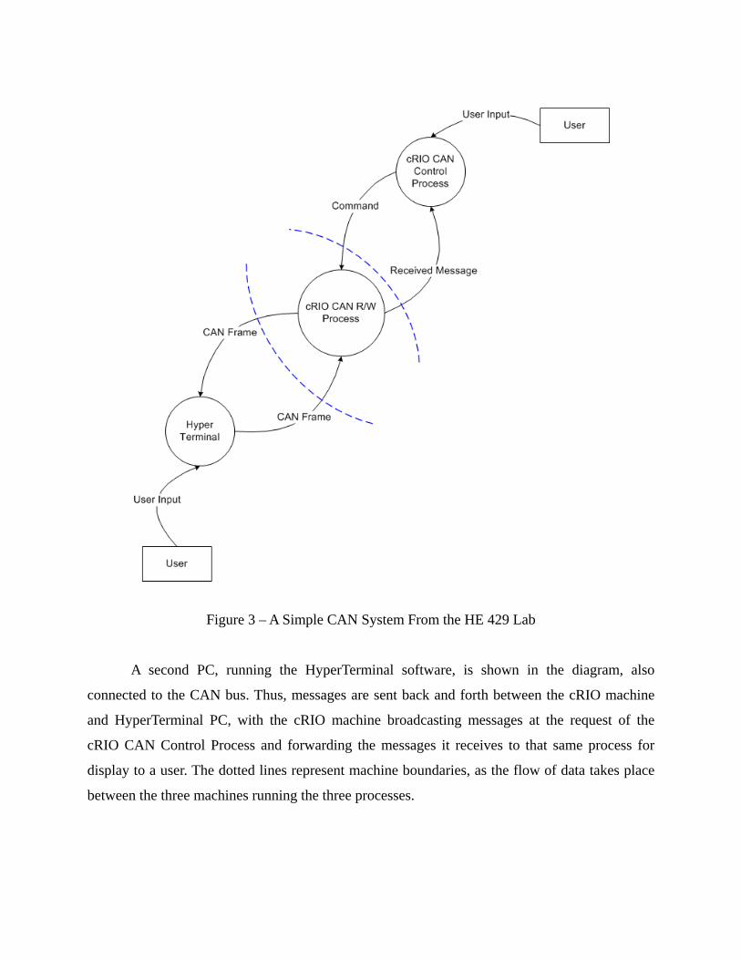
Figure 3 – A Simple CAN System From the HE 429 Lab
A second PC, running the HyperTerminal software, is shown in the diagram, also
connected to the CAN bus. Thus, messages are sent back and forth between the cRIO machine
and HyperTerminal PC, with the cRIO machine broadcasting messages at the request of the
cRIO CAN Control Process and forwarding the messages it receives to that same process for
display to a user. The dotted lines represent machine boundaries, as the flow of data takes place
between the three machines running the three processes.

Figure 4 – The MS SDL Threat Modeling Tool Displaying Potential Threats
Despite the simplicity of the system and corresponding DFD, the Microsoft SDL Threat
Modeling Tool was able to identify a distinct thirty-nine (Figure 4) potential threats by checking
flows of data between processes and boundaries, and suggest various ways to determine whether
a real threat existed along with potential countermeasures. The tool further classifies each threat
according to its STRIDE category, with many processes and data flows having threats from
multiple categories.

Figure 5 – A Specific Threat Viewed in Greater Detail
A specific threat is selected for analysis in Figure 5, at the data flow from the "cRIO
CAN R/W Process" to the Hyper Terminal node. As shown by arrow 1, this data flow is to be
checked for Tampering threats. The tool provides some suggestion for how to look for threats to
this data flow, such as whether "all endpoints [are] mutually authenticated with keys obtained
[...] out of band". However, the tool does not automatically determine whether any of these
criteria are present, instead presenting several possible criteria to check.
This is an example of what the SDL tool actually does: rather than identifying threats, it
compiles a list of places to check for threats, such as anywhere data flows from one process to
another. The specific threats the tool suggests to check for depend on the type of the DFD
element being examined. For example, all DataFlow elements (arrows) in the example diagram
(Figure 4) are flagged with Tampering, Information Disclosure, and Denial of Service threats.
Each of the processes are flagged with all six of the STRIDE threats, and each Interactor (user) is
flagged with a Spoofing and a Repudiation threat.
It is the job of the developers to manually check every single element for every threat
type associated with that element, and certify that the threat does not apply, that the risk
associated the threat mitigated in some way, or that the risk is simply accepted (Arrow 3). The
developers then record the reasoning behind their decision (Arrow 4). Finally, the tool also offers

some advice (Arrow 5) on using the tool with regards to explaining the developers' decision to
handle a threat.
2.2 Trike Threat Modeling Tool
2.2.1 Trike Methodology
The Trike threat-modeling tool was developed to fascilitate threat modeling according to
the Trike methodology, a defensive, systematic approach to threat modeling. A major difference
between the Trike methodology and the Microsoft SDL methodology presented previously,
beside the defensive nature of Trike, is Trike's focus on starting the threat modeling process early
in the software development lifecycle. Whereas the Microsoft approach typically begins in the
design stage, the Trike methodology calls for threat modeling to begin in the requirements
specification stage, so that developers may design around threats in the following design stage.
[3]
Instead of simply decomposing the system during the design stage, when there is an
existing, if non-final, design, Trike calls for analysis to begin before the design stage, with a
Requirements Model. At this stage in process, the software requirements are examined to
determine actors, assets, intended actions, and rules for those actions. The Trike methodology
gives these terms, and others, a strict meaning. [3]
An actor is a human agent who interacts with a part of the system that is relevant to the
function or purpose of the system. Thus, an administrator managing data associated with the
system would not be considered an actor, unless a goal of the system was to fascilitate such
management. An asset is an object (typically data) with some meaning to the system that must be
protected. Again, relevance to the problem domain or "business rules" is necessary - passwords,
for example, would not count as assets, as they themselves are a specific means of protecting
data. [3]
Actions are defined as "things which actors do to assets." In accordance with the Trike
methodology, an action on a virtual object may be composed into some combination of create,
read, update, or delete (CRUD) actions. The methodology does distinguish between actions in
general and "intended" actions, which the system was specified to support. [3]
Formally, an intended action is a combination of an action, an asset, and rules specifying
which actors may take that action on that asset, and in which situations they may do so. It is

important that every desired function of system has a corresponding intended action. Note that
Trike does not forbid the inclusion of actions on physical objects, but currently does not treat
them, as the methodology is focused on software development. Rules are simple declarations,
combined by logical connections, specifying the situations in which particular actions may occur.
[3]
After the requirements model has been developed, developers may immediately start
looking for threats for the threat model, or construct an "implementation model". This is another
facet of Trike that differs from the Microsoft method: not only may threat modeling begin in the
requirements stage, threats may be determined immediately afterward, before design and
implementation of the system is discussed. This is because Trike has its own way of defining
threats. [3]
In Trike, a threat is defined as "anything which is more or less than the intended actions,
as these represent everything that can be done in a secure system." The methodology draft clearly
expresses that threats cannot be implementation-specific - for example, a data store containing
user account information could have an information disclosure threat going by previously
discussed methods, but not by Trike. [3]
In fact, deviating from the STRIDE criteria, the Trike methodology considers all threats
to belong to either of the denial of service and elevation of privilege categories. The former is
said to occur when an actor is prevented from taking an intended action, the latter is said to occur
when an actor uses the system to perform an action that he or she should not be able to perform.
Spoofing, for example, is considered to be a specific attack as part of an elevation of privilege
threat. [3]
As for the "implementation model," the developers must distinguish between intended
actions, which are part of the application domain, and "supporting operations", which are
implementation- or design-specific actions taken by users to interact with the system. Afterward,
a data flow diagram is constructed to model the system, as discussed previously. [3]
The methodology draft also explains that supporting operations alter the state of the
system, rather than the assets, and suggests that use-flows are developed to reflect all possible
states of the system with regards to supporting operations and intended actions. The document
also states that actually enumerating all such states is typically prohibitively difficult for all but
trivial systems, and offers no advice for overcoming such difficulty. None of these

implementation model concepts are implemented in the Trike tool, and all are considered "highly
experimental" and "likely to change" as of 2005. [3]
After the requirements and implementation models have been specified, threat modeling
is supposed to take place in the same manner as explained in a previous section. The security
expertise of developers is leveraged to discover specific attacks based on the models developed
and threats discovered. None of the implementation-model-specific steps are included in the
current Trike tool, however. [3][9]
At the time of this writing, the latest draft of the Trike methodology is v.1. The team
maintaining Trike is "actively coding for the first release for the v2 methodology, which [they]
intend to be a Real Tool, vs. a prototype." Progress is unclear, as the team follows that statement
with "The earliest you should expect to see a v2 tool is Q1 2009." [11]
2.2.2 Trike Tool
The Trike tool is a prototype last updated before 2009. [11] It allows a user to define
actors, assets, actions, and attacks in accordance with the Trike methodology described above.
Similar to the Microsoft SDL tool, it allows a user to specify some properties of a system, then
enumerates all the possible threats, regardless of their relevance to the system under
consideration (also like the SDL tool). It does this by enumerating all possible CRUD actions
that may be taken on the specified assets by the specified (and unspecified) users, and requiring
the developer to decide which of these apply to the system in question. [9]
The Trike tool provides no graphical means of decomposing a system using DFDs,
instead requiring the user to find a separate diagramming program. However, it makes no use of
such diagrams itself – those would only be useful to a developer using the Trike tool to record
their own observations. [9] It is, however, a stated goal of Trike is to automate "the repetitive
parts of threat modeling", including automatic threat generation and limited attack generation.
[11]
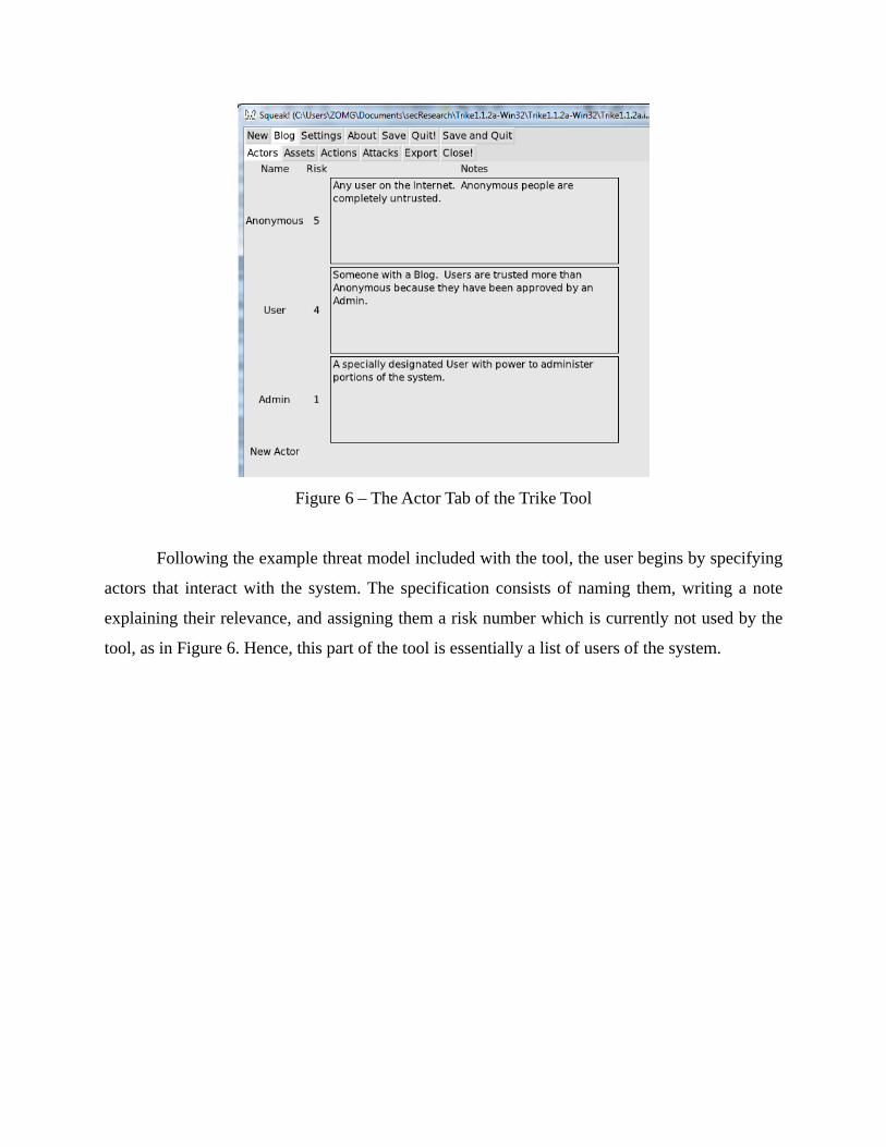
Figure 6 – The Actor Tab of the Trike Tool
Following the example threat model included with the tool, the user begins by specifying
actors that interact with the system. The specification consists of naming them, writing a note
explaining their relevance, and assigning them a risk number which is currently not used by the
tool, as in Figure 6. Hence, this part of the tool is essentially a list of users of the system.

Figure 7 – The Assets Tab of the Trike Tool
Assets (Figure 7) are handled by the tool similarly: the user lists several assets, each with
a note explaining their inclusion. The user also assigns numerical values to the assets, and marks
whether each asset is within the scope of the system or an external asset that may be
compromised if the system is exploited. Again, neither the numerical values nor the assigned
scope are used by the tool.

Figure 8 – The Actions Tab of the Trike Tool
Actions are where the tool begins to perform some automation. After actors and assets
have been specified, the tool automatically generates CRUD-based actions for every combination
of virtual action type, user, and asset. Thus, a system with four actors and five assets would have
4 x 5 x 5 = 100 possible actions enumerated, with the Trike tool user being required to decide
whether those actions are intended and specify rules for them to be taken, as in Figure 8.
Figure 9 – The Attacks Tab of the Trike Tool

Attacks are specified similarly. In accordance with the Trike methodology, unintended
actions that do not support operation are considered to be threats, and attacks are methods of
realizing those threats (Figure 9). Thus, the system enumerates all possible threats as
combinations of actor, asset, and CRUD-based action, and leaves the developer to decide which
of these threats are relevant and how attackers could implement them.
Overall, the Trike tool appears to be of little use in a typical threat modeling process that
decomposes a proposed systems using DFDs and classifies threats according to STRIDE. This is
because it was constructed specifically to facilitate the use of the Trike approach to threat
modeling. However, within a threat-modeling process that follows the Trike methodology, it still
offers little more than automatic enumeration of threat types, in the form of a list of unintended
actions for developers to consider and work to ensure are unlikely to occur. Essentially, it creates
a check-list of actions to consider for each asset. This is compliant with one of the stated goals of
the Trike tool, to automate repetitive parts of the threat-modeling process, but may not justify the
use of this tool over the Microsoft SDL tool, especially as the Trike methodology, which the tool
assists, is itself incomplete.

3. Threat Modeling in Embedded Systems
Secure embedded software development comes with additional challenges due to the
nature of the devices running the software. These challenges stem from embedded devices often
having few resources, modifiable firmware, intermittent or insecure network access, and a small
physical size or other physical property that makes physical tampering an easy task. [13][15][16]
The major parts of the threat modeling process, system decomposition, threat evaluation, and
attack tree generation, are directly applicable to embedded systems. The system in question is
still decomposed into its component parts at varying levels of detail and checked for threats.
Attack trees are still dependent upon the design and implementation of the system, which implies
that what changes when the threat modeling process is directly applied to embedded systems is
the nature of the attacks. Thus, this section presents a brief survey of various attacks, both
specific and general, on embedded systems.
Embedded systems, particularly in the industrial and automotive domains, are part of
complex networks. Such systems may be vulnerable to attacks based on the nature of their
network protocols, particularly in the cases of those systems that use CAN or MODBUS to
communicate. [12][13]
The CAN protocol itself presents several challenges to developers of secure embedded
system software. Since nodes communicate with each other through broadcasts on the CAN bus,
a single compromised node may be used to monitor communications or send packets that are
indistinguishable from legitimate nodes. Such a node may be used to realize information
disclosure, spoofing or denial of service threats. [13][14]

4. Example of an Automotive Network
In this section, the threat-modeling process is performed on a subset of the computing
components contained in a typical modern automobile. Several threats are considered, along with
the feasibility of realizing them through various attacks. It was found that gaining access to an
automobile's intra-vehicle network was sufficient to realize virtually any threat. [14] Thus, for
any threat discussed here, the attacks will focus on achieving access to the vehicle's internal
network.
Modern automobiles may contain as many as 70-80 different electronic control units
(ECUs). [14] These ECUs have different purposes, such as controlling door locks, anti-lock
brake systems, airbags, cruise control, and telematics units, among others. As these uses have
different degrees of importance, there are several different kinds of buses in the modern car, with
more expensive, fast, and reliable buses connecting ECUs that control critical vehicle
components, and cheaper buses for those ECUs that control less important applications, like door
locking. [13]
Despite the use of multiple buses for networking groups of ECUs with different
communication needs, in-vehicle networks are bridged to allow subtle interactions between
them, such as a car's central locking systems being connected with critical crash detection
systems so that car doors may be unlocked after a crash. [14] This interconnection of a car's
distinct networks allows all ECUs to be compromised after an attacker gains control of any
single ECU. [14] This allows many different threats to realized, including preventing the brakes
from engaging and eavesdropping on cabin audio, to name two. [18]

Figure 4.1.1 – Diagram Showing Both the Vehicle's Flow of Data and Network Connection
For the sake of simplicity, the only components to be considered in the following threat
model are the Engine Control Module (ECM), the Electronic Brake Control Module (ECBM),
the Body Control Module (BCM), and the Telematics Module (Figure 4.1.1). The ECM is
responsible for using sensor information to determine engine parameters such as ignition timing.
The EBCM controls the ABS and the BCM controls vehicle functions like doors locks, power
windows, etc. The telematics module connects to a cellular network for remote communications.
Though an attacker with access to a vehicle's internal network may control any ECU in
the entire vehicle, it may not be clear why exactly an attacker would wish to do so. An attacker
wishing to damage the vehicle could simply do it physically for far cheaper, for example. An
attacker wishing to do harm its owner(s) could disable the brakes physically as well. However,
there may exist other motives, discussed in [18], such as enabling theft, or remote surveillance.
Someone with access to a car's network (and thus, telematics module) would be able to
eavesdrop on conversations from within the car, for cars with in-cabin microphones.

Such access also allows the location of the car to be tracked, for general surveillance
purposes or to determine that the car will be left alone for some time, facilitating theft as the
doors may be unlocked and engine started remotely for an unskilled accomplice to steal the
vehicle. [18] It was also suggested [18] that an attacker could compromise many cars and simply
sell their locations and access to other thieves. Thus, there exist known possible motives for an
attacker.
Figure 4.1.2 – Overview of attacks to gain CAN access

Figure 4.1.3 – Attack tree for connection to OBD-II port
Figure 4.1.4 – Attack tree for direct connection to vehicle's network
For any threat, discussed above, a sufficient condition for realization is for an attacker to
gain access to the vehicle's CAN network (Figure 4.1.2). Thus, all attacks considered will work
toward gaining CAN network access as their ultimate goal. The most obvious way for an attacker

to gain access to the network is through direct physical access. Anyone with access to the vehicle
may connect a component to its network via the vehicle’s on-board diagnostics (OBD-II) port
(Figure 4.1.3). [14] For some cars, it may be possible to break one of the outside electronic
mirrors and connect to the network via a mobile computer (Figure 4.1.4). [13] In general, attacks
like these that require an attacker to access the car directly are considered unlikely.
Figure 4.1.5 – Attack tree for remote attack via cellular network
More attacks are described in [18], but only one will be described here. Using the car’s
telematics unit, an attacker may access a vehicle’s internal network from indefinite range through
cellular communications networks. The telematics unit is typically used to connect to a
manufacturer’s Telematics Call Center (TCC), but by reverse engineering the communications
protocol used by the unit, researchers in [18] were able to call their car’s telematics unit directly

and force it to download malicious code via a 3G Internet connection. The entire attack tree is
illustrated in Figure 4.1.5.
The next step is to evaluate the risks associated with each attack based on its feasibility
and potential impact if enacted. Clearly, all of the attacks described could have severe negative
effects, since they all allow any kind of threat to be realized. However, they are not all equally
feasible. If an attacker has access to a car’s cabin and can attach malicious component, then it’s
possible to simply steal the car outright. There are also easier ways to track vehicle movements
and eavesdrop on conversations once that access has been obtained. Thus, there seems to be very
little reason for an attacker to choose that method over less-sophisticated and less-costly attacks.
Similarly, if an attacker is willing to break an electronic mirror (and expose his/her attack) to
connect to its underlying network, then it would be possible to break a window and attach a
malicious component directly to an OBD-II port inside the car. These risks would likely be
accepted.
As for the long-range cellular attack shown in <attack tree figure #3>, consequences of a
successful attack are no less severe. However, the feasibility of an attack is increased, as an
attacker no longer has to obtain direct physical access to the vehicle. Threats realizable through
this attack would likely be mitigated through fixing key bugs in the telematics software that
allowed it. In this case, the attack relied on a bug in the telematics unit’s authentication software,
in that it simply authenticated callers that it shouldn’t have, allowing attackers to call it and
download their malicious software. [18]

References
[1] M. Howard, D. LeBlanc, Writing Secure Code, 2nd Ed., Microsoft Press, Redmond,
Washington, 2003.
[2] S. Myagmar, A. J. Lee, W. Yurcik, Threat Modeling as a Basis for Security Requirements,
StorageSS '05: Proceedings of the 2005 ACM workshop on Storage security and survivability
(2005), pp. 94-102, 2005.
[3] P. Saitta, B. Larcom, M. Eddington, Trike v.1 Methodology Document [Draft], July 13th,
2005,
http://octotrike.org/papers/Trike_v1_Methodology_Document-draft.pdf
[4] J. Steffan, M. Schumacher, Collaborative Attack Modeling, SAC '02: Proceedings of the 2002
ACM symposium on Applied computing (2002), pp. 253-259, 2002.
[5] J. A. Ingalsbe, L. Kunimatsu, T. Baeten, N. R. Mead, Threat Modeling: Diving into the Deep
End, IEEE Software, Vol. 25, No. 1 (2008) pp. 28-34, January/February 2008.
[6] D. Dhillon, Developer-Driven Threat Modeling, IEEE Security & Privacy, Vol. 9, No. 4
(2011) pp. 41-47, July/August 2011.
[7] B. Schneier. Secrets & Lies, Wiley Publishing, Inc., Indianapolis, Indiana, 2004.
[8] Microsoft, Microsoft Threat Analysis and Modeling Tool v3.0, 01/31/2012,
http://archive.msdn.microsoft.com/tam
[9] octotrike.org, Trike, 01/31/2012, http://octotrike.org/tools.shtml
[10] Microsoft, Microsoft SDL Threat Modeling Tool, 02/05/2012
http://microsoft.com/security/sdl/adopt/threatmodeling.aspx
[11] B. Larcom, E. Saitta, Trike: FAQ, 02/12/12, http://octotrike.org/faq/
[12] E. Byres, M. Franz, D. Miller, The Use of Attack Trees in Assessing Vulnerabilities
in SCADA Systems, International Infrastructure Survivability Workshop (IISW '04), December
4, 2004.
[13] M. Wolf, A. Weimerskirch, C. Paar, Security in Automotive Bus Systems, Proceedings of
the Workshop on Embedded Security in Cars (escar)’04, 2004.
[14] K. Koscher, et al., Experimental Security Analysis of a Modern Automobile, Proceedings of
IEEE Symposium on Security and Privacy, 2010.
[15] M. LeMay, C. A. Gunter, Cumulative Attestation Kernels for Embedded Systems, In
Proceedings of the 14th European Symposium on Research in Computer Security, pp. 655-670,

21-23 September 2009.
[16] Klocwork, Threat Modeling for Secure Embedded Software, Klockwork,
www.klocwork.com, June 2011.
[17] N. Potlapally, Topics in Secure Embedded System Design, January 2008.
[18] Checkoway, et. al., Comprehensive Experimental Analyses of Automotive Attack Surfaces,
www.autosec.org/pubs/cars-usenixsec2011.pdf, March 2011