Embed Size (px)
Citation preview
AD-A257 674 "' •
MTL TR 92-26 AD-A257 6AD
LAV ARMOR PLATE STUDY
MARTIN G. H. WELLS, REBECCA K. WEISS, andJONATHAN S. MONTGOMERYMETALS RESEARCH BRANCH
THOMAS G. MELVINMATERIALS PRODUCIBILITY BRANCH DTIC._"
ELECTEDECO 2 19923
April 1992 AA
Approved for public release; distribution unlimited.
92-30563
Sponsored by
U.S. Army Tank-Automotive CommandWarren, MI
US ARMYLABORATORY COMMAND U.S. ARMY MATERIALS TECHNOLOGY LABORATORYMATEIMS •TEOIIooGY uM.oTv Watertown, Massachusetts 02172-0001
, , . ..... . ... . . . . . . i . . . ... . Ii . . . .. .
The findings in this report are not to be construed as an officialDepartment of the Army position, unless ,o designated by otherauthorized documents.
Mention of any trade names or manufacturers in this reportshall not be construed as advertising nor as an officialindorsement or approval of such products or companies bythe United States Government.
DISPOSITION INSTRUCTIONS
Destroy this report when it is no longer needed.
Do not return it to the originator.
UNCLASSIFID
SECUIWY CLASSIFICATION OF THIS PAGE (Dkam D Eb.ood)REPORT DOCUMENTATION PAGE RED INSTRUCnONS
BEFORIE COMPLETING FORM
7 -PoR NUMBER2. GOVT ACCESSION No. RECIPIENT'S CATALOG NUMBERMT TR 92-26
4. TILE (dd Sabk) 5 TYPE OF REPORT & PERIOD COVERED
LAV ARMOR PLATE STUDY Final Report
a PERFORMING or. REPORT NUMBER
7. AU1HOA() &. CONTRACT OR GRANT NUMBER(s)
Martn i . IK WeCI, Rebema K. We".s, Jonathan S. Montgomery,and Thomas 0. Melvin
9. PERFOAM OIGANIZATION NAME AND ADDRESS 10. PROGRAM ELEMENT. PROJECT. TASK
U.S. Army Materials Technology Laboratory AREA & WORK UNIT NUMBERS
Watertown, Massachusetts 02172-O01SLCMT.EMM
11. CONTROLLING OFFICE NAME AN ADDRESS 12. REPORT DATE
U.S. Army Tank-Automotive Command April 1992Warren, MI 48397-5000 13. NUMBER OF PAGES
26
14. MONITORING AGENCY NAME & ADDRESS (fd,•iffuim C~Wlie, O0") 1&. SECURItY CLASS. (f" ,,pm,,)
Unclassified
ISD. 0ECLASItICATIONDOWNGRADINGSCHEDULE
ID. DISBUTION TATEMENT (of, ak r,,)
Approved for public release; distribution unlimited.
17. OITUBT1O4STATEMENT (of Es rab .mw~im E&* 20. ~ifA&fw.vm'u.que)
IS. SUPPLEMENTARY NOTES
10. KEYWORDS (Cawima an mom Fl Mfemo, ' • •d • i•*i by bioc mynbv)
Steel armor WeldingHigh hardness armor Mechanical propertiesLight armored vehicles (LAV) Cracking
20. ABPRACT (Caukw.e amw *4. ,fw y ' aid im*f by U6•ck un,,bw)
(SEE REVERSE SIDE)
FORM EDITION OF I NOV 8 IS OBSOLETE
1 JAN 73 U UNCLASSIFIED
SECURITY CLASSIFICATION OF THIS PAGE (MIam Dag, Eiwfd)

UN- MASSIEDSECUNnY Ct•IGICATION OF THIS PAGE (ftm Dive &Ww94
ABSTRACT
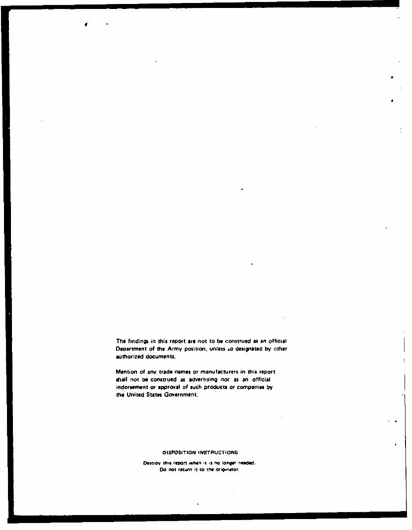
This study was undertaken to determine the cause of cracking in high hard armorsteel plates used in the manufacture of light armored vehicles (LAVs) and to make rec-ommendations to alleviate the problem. Cracks in several components from fielded vehi-cles were analyzed. In many cases the cracking was found to be caused by improperedge preparation in cutting the steel which resulted in environmcntally-assisted cracking.Cracks were also observed starting from welds which were attributed to a number of pos-sible causes: stress-corrosion cracking, hydrogen-assisted cold cracking, and cracking dueto extremely harsh vehicle use. Base metal mechanical properties, including hardness,tensile strength, and Charpy V-notch impact energy were measured from room tempera-ture to -40°-F (-40°C). Ballistic properties were measured and the propensity of thesteel to crack under ballistic impact conditions was also evaluated. Additionally, thestudy involved a review of MIL-A-46100 and the new Canadian Material Specification,CMS.18.
UNCILASFIEDSECUWNTY CLAUIFICATUOM OF THIS PAGE (WM iW E0M&
CONTENTS
Page
INTRODUCTION ................................................ I
MATERIALS AND TESTING PROCEDURES
Failed Components ........................................... I
M aterials .................................................. 2
Ballistic Testing ............................................. 3
RESULTS AND DISCUSSION
Analysis of Cracked Components and Plate Edges ....................... 3
M echanical Properties ......................................... 5
Ballistic Properties ........................................... 8
W elding .... .... ......................... ........... ...... 9
Steel . . .... . ... . .. . . ...... .. .. .... . .. ... .. ... . .... . ... . .. 10
SUMMARY AND CONCLUSIONS
Cracking ........ .......................................... 12
M echanical Properties ......................................... 12
Ballistic Properties ........................................... 12
RECOMMENDATIONS .............................. ............. 13
ACKNOWLEDGMENTS ............................................ 13
NTIS
O ,iC i..-,
Ju~tli•-a:Voe;.......... ..
By......-....Distt
A-1................ .... .. .
INTRODUCTION
The original mission was to address concerns of the suitability of MIL-A-46100 High Hard-ness Steel Armor in the structural application of the light armored vehicle (LAV). 1
The family of LAVs made for the U.S. Marine Corps (USMC) were fabricated from lightgage (4.71 mm to 9.71 mm nominal thickness) high hardness steel armor (MIL-A-46100)above the beltline. This was one of the first uses of high hard armor in a welded structuralapplication. High hardness steel armor is tempered at low temperatures, below the temperembrittlement range and in the first stage of tempering, and the resulting strengthening disper-sion consists of epsilon carbide. The steel was chosen to maximize ballistic protection againstthe defined threat (7.62-mm M1943 ball, AK47 round) while maintaining vehicle lightness.Other authors had strongly recommended against continued use of this steel because of itspurportea brittleness. Many vehicles had exhibited cracks of varying severity in the steelplate. However, the U.S. Army Materials Technology Laboratory (MTL) approached the prob-lem from a aiiL''crent viewpoint.
Since vehicle production of this series had been completed, the object of the study wasto determine the cause of cracking, to examine weld repair procedures and to recommendsteel compositions and manufacturing procedures to minimize cracking in the present and fu-ture vehicles. An examination of failed components was made, mechanical and ballistic proper-tics of representative plates measured, and other available information reviewed.
MATERIALS AND TESTING PROCEDURES
Failed Components
Several parts of fielded LAVs containing cracks were received for analysis. Most ofthese 'ailures had occurred much earlier and the crack surfaces were quite rusted. However,based upon the pieces examined and previous studies, the failure mechanisms are thought tobe similar; therefore, this report details cracks in a hatch cover and a rear door.
Plate cutting and grinding procedures used during vehicle manufacture are thought to playan important role in determining vehicle integrity. Plate samples cut by plasma-arc in air,plasma-arc under water, oxyacetylene, carbon-arc in air, dry abrasive cutting wheel, and laserwere obtained for examination. These samples were then sectioned for metallographic exami-nation and microhardness traverses.
When this study was initiated, a vehicle lifting restriction was in place. No lifting was permit-tcd at ambient temperatures below 320 F (0°C). Two LAVs had been dropped from helicoptersand the cause was not immediately apparent, although subsequently it was determined that bothvehicles were dropped intentionally because of helicopter malfunctions. The following phrase inMIL-A-46100B and C under Paragraph 6.1 (Intended Use) was also of concern:
"The steel armor covered by this specification is intended for structural use in
lightweight applications generally up to and including 1-1/2 incheb in thickness,operating at temperatures in excess of 32 0 F, where resistance to ball and armorpiercing types of ammunition and multihit capability are required."
I. KREN7KE. M.A. LAV Cracking Problem Investxgatiot and Anaris Study Eastima. Memorandum[ Deparlmenl o( Ihe Navy,David Taylor Research Center, Annapolis, MD, 13 January 1989.

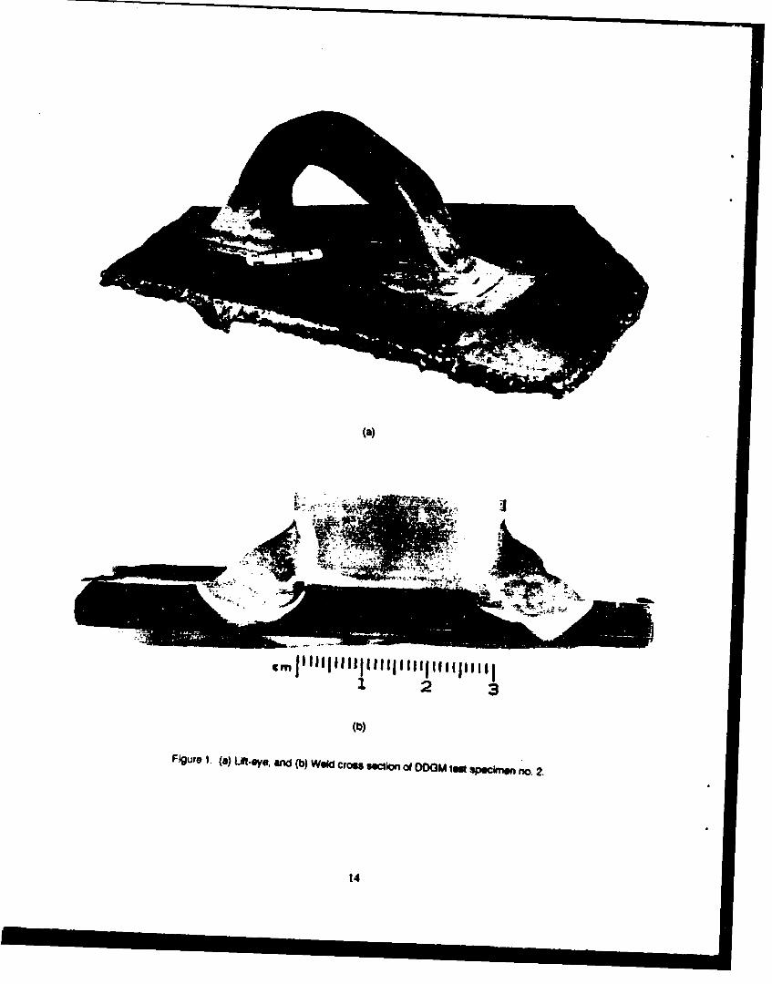
In a separate but closely related study,2 several mock-up lift-eye structures of the rightfront eye were tested at room temperature and at -25°F (-320C). In addition, actual vehiclelift tests were conducted at the same two temperatures. Details of the testing are given inan MTL Letter Report. 2 The MTL test results closely agreed with previous data from Gen-eral Motors and as a result the lifting restriction was removed.
For completeness, some details of the lift-eye structure are given below. The LAV lift-eye is fabricated from ASTM A 514, Grade S, steel of the following composition (wt%):
C Mn SI P S Mo B
0.17 1.38 0.32 0.005 0.008 0.28 0.0010
The eyes, about 1' x 1-114" in cross section, are welded to the vehicle side panels(7.31 mm thickness). A view of one of the eyes is shown in Figure la, and a cross sectionof the weld in Figure lb. The three-pass weld can clearly be seen; it consists of an initialroot pass followed by a second pass along the high hard armor plate, and finally a third passagainst the eye.
Materals
For this study, four steel plates of MIL-A-46100 high hardness armor steel were orderedfrom the Diesel Division of General Motors (DDGM). These plates are typical of materialfor LAV production and were made by the Lukens Steel Company to MIL-A-46100C (Revi-sion C). The chemical analysis of these plates is given in Table 1.
Table 1. CHEMICAL ANALYSIS OF MATERIAL USED IN THIS STUDY
Composition 6.31 mm 7.31 mm 7.31 mm 9.71 mm
(Wt%) (1/4 in.) (9/32 in.) (Extra Hard) (3/8 In.)
C 0.29 0.31 0.31 0.31
Mn 0.83 0.87 0.87 0.96
NI 0.90 1.16 1.16 1.10
Cr 0.47 0.54 0.54 0.52
Mo 0.53 0.55 0.55 0.55
SI 0.38 0.43 0.43 0.39
AN 0.030 0.036 0.036 0.025
P 0.015 0.010 0.010 0.015
S 0.001 0,002 0.002 0.003
HRC 48 50 51 48
Plate Dimenslobs (In.) 65x 165 65x 220 65 x 220 72x 100
NOTE: The how treatment wa as follows:Aumeltlzkng 1660°F (904°C) - 20 mlinSpray Water (Roller Quench) 4000F (204C) ~O mln tc" 3 ple
30 min for the extra Iwd (XH) plate
2. BETHONEY, W. M., and CRENSHAW. W. L ULW Amoed Vahkk (LA Fj) L1t Hook Te. U.S. Army Materials TechnowoLaborat•r, Letter Report, September, 1969.
2
Hardness and microhardness measurements were made both on the plate surface and onpolished cross sections. Tensile and Charpy V-notch impact measurements were made in. thelongitudinal and transverse directions. The tensile specimens were flat, 3/16 in. thick with a2 in. gage section. The Charpy specimens were all half size because of the original platethickness. Equal amounts of material were removed from both surfaces in the preparation ofthese mechanical test samples.
Ballistic Tostng
The LAV is principally designed to defeat a 7.62-mm M1943 ball threat (AK47,muzzle velocity 2380 ft/s). It would also be desirable to defeat other heavier threats such as12.7-mm (.50 cal) APN and even 14.5-mm projectiles. In the latter cases the design threatwould be at lower velocities, i.e., greater stand-off distances, against armor at high obliquities.There was also a lack of data on MIL-A-46100 at low temperatures; therefore, it was decidedto run a series of ballistic tests on the four plates described above. Three threats were cho-sen: 7.62-mm M1943 ball, 12.7-mm (.50 cal) API B32, and a 20 mm 70 g proof round. Theblunt- (flat-) nosed proof round was used to determine the propensity of high hard steelarmor plate to crack under ballistic shock loading conditions, particularly at low temperatures.The proof rounds were made from AISI 1018 plain carbon steel. A photograph of the threeprojectiles including dimensions is shown in Figure 2.
The V50 values were obtained according to the Ballistic Protection Limit criterion. A wit-ness plate of 0.020 in. thick aluminum is placed *behind the target and any penetration ofthe witness plate by either the projectile or parts of the projectile or target, i.e., back spalls,plugs, etc., is defined as a target penetration. The V50 velocity is then the average velocityof the three projectiles (sometimes two were used) with the highest velocities that do notpenetrate the target and the three (or two) with the lowest velocities that penetrate the tar-get. Projectile velocities are varied by and are dependent upon the amount of charge in thecartridge.
The measurements at a test temperature of -40OF were made by first pre-immersingthe subject plate in a low temperature freezer overnight at a temperature significantlylower than the test temperature. When ready for testing, the plates were removed fromthe freezer and placed in the target rack. The plate temperature was continuously moni-tored with a thermocouple and when it reached -40OF one ballistic test (one shot) wasmade. The plate then went back into the freezer and the cycle continued until testing ofthe plate was completed.
RESULTS AND DISCUSSION
Analys" of Cracked Component. and Plate Edges
Rear Door
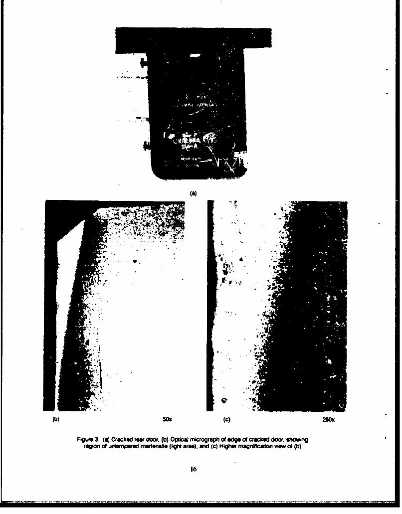
Figure 3a shows a cracked door from an LAV-25. Microscopical examination for theedge of tlfe plate at the cr.ck origin revealed a layer of untempered martensite, as shownin Figure 3b. As discussed below, this layer results from the plate cutting operation andwas not completely removed during subsequent grinding. This layer of untempered martens-ire is quite brittle and can be a crack initiation site. The Charpy V-notch impact energy ofthe plate in this door was measured in the longitudinal (LT) and transverse (TL) directions
3
(3/4 size specimens) from room temperature (72GF) to -400F. No sharp transition temperaturewas observed (see Figure 4). The shape of the curve is typical for very high strength steels. 3
Figure 5 depicts a typical cross section of the door showing the fine banding in the inte-rior and the decarburization at the edge. Banding is present in all steels, to a greater orlesser degree, whether it is ingot or continuously cast. The banding results from local segrega-tion (mainly of carbon) during the solidification process and, hence, will cause slight hardnessvariations. This example is shown to illustrate that care must be takcn when evaluating micro-hardness traverses.
Turret Hatch Cover
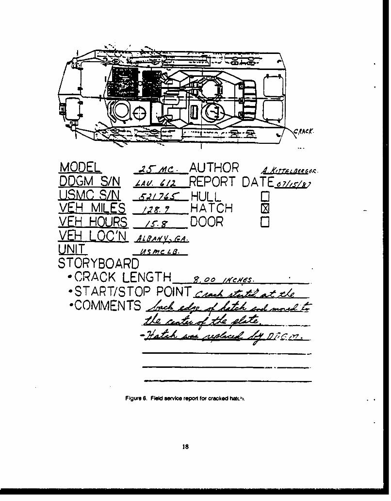
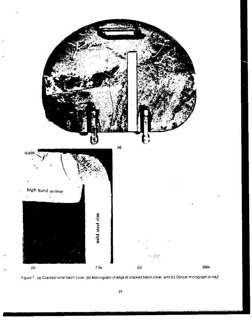
A cracked turret hatch cover from a vehicle Model Number 25MC,DDGM S/N LAV 612,USMC S/N 521765 was received for evaluation. A copy of the field service report of thecrack in this hatch is given in Figure 6. The crack length when the hatch was replaced on15 July 1987 was 8 inches. 4 The crack has since grown to over 12 inches and may be seenstarting at the weld at the rim and travelling into the center (see Figure 7a). During cut-outof the crack origin region, binding of the saw occurred and it was evident that considerable re-sidual stress was being relieved. A macrograph of the rim weld and micrograph of the struc-ture of the weld region are shown in Figures 7b and 7c, respectively. Again, there is a layerof martensite next to the weld metal. Typical microhardness traverses across a weld regionare shown in Figure 8. This sample was taken from the weld between the right upper frontquarter panel and the main front" glacis from the LAV that was dropped at Camp LeJeune(now at MTL). As this is a two-pass weld, two traverses were performed: the first justbelow the front surface (first pass), and the second just below the back surface (second pass).Moving from the weld metal to the base plate, the wide variation in hardness is readily appar-ent. The weld nugget is quite soft; then, after the fusion zone, there is a layer of very hardfresh (as-quenched) martensite in the base metal heat-affected zone (HAZ) that resulted fromre-austenization during welding. The base metal HAZ hardness then drops into the regionthat did not see a high enough temperature excursion to be re-austenitized and so instead be-came heavily tempered. Following that, the steel is progressively less tempered during thewelding operation and the hardness rises asymptotically to that of the (unwelded) base plate.
The cracking observed initiating from free-cut plate edges was often very similar to thatobserved in previous studies. 5'6 It was concluded that much of the cracking occurring inLAVs from free-cut plate edges may be attributed to environmentally-assisted cracking. Forthis mechanism to operate, the following conditions are necessary:
"* A notch or crack initiation site must be present, e.g., quench cracks,
"* The plate (component) must be under tensile stress (either residual or applied in service),
"* The component must be in a suitable environment, and
"* The material must be in a condition susceptible to environmentally-assisted crack propa-gation, e.g., untempered or first-stage tempered martensite.
3. ROLFE, S. T., and BARSOM, J. M. Frwacre and Fatip Convol in Sucnow. Prenfice-Hall. EnglmmWod Cliff, NJ, 1977.4. LAV-PMO. LA V 0ack Stai Rport. TACOM, Detroit, Mi. 2 December 1987.5. HERMAN, W. A. and CAMPBELL, G. M. Envnmaua Anisted Cracking in High Hardme Amw Steel. U.S. Army Materiasi Technol-
o 14 .Abttoy, MTL TR 85.28, September 1965.6. PHILLIPS, R. H. ct &I. De/ayed Fracture of Hisf Ifardnhn Ann~o Steel. Australian Department o( Defence, DSTO, Materials Research
L.sboratory, Australia, Final Repon on TrCP ITP-I Study Assignment FTP-A-SI, December 1990.
4
In the case of the LAV the latter three conditions exist in service and little can be doneto change these given conditions, therefore, the risk of crack starters must be reduced. In ve-hicle manufacture, individual plate pieces are cut to shape by an underwater plasma.arc pro-cess. This procedure produces a layer of very hard, brittle untempered martensite at the cutedge that must be removed as soon as possible after cutting. Alloy steels in this conditionare susceptible to a phenomenon known as delayed cracking. Some LAV components exam-ined at MTL exhibited residual untempered martensite at free-cut edges that had not beencompletely removed during grinding.
Cut Edges
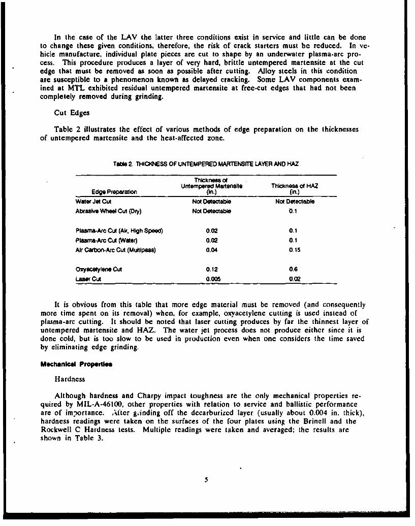
Table 2 illustrates the effect of various methods of edge preparation on the thicknessesof untempered martensite and the heat-affected zone.
Table 2. THICKNESS OF UNTEMPERED MARTENSITE LAYER AND HAZ
Thickness ofUntempered Martensite Thickness of HAZ
Edge Preparation (in.) (in.)Water Jet Cut Not Detectable Not DetectableAbrasive Wheel Cul (Dry) Not Detectable 0.1
Plasma-Arc Cut (Air. High Speed) 0.02 0.1Plasma-Arc Cut (Water) 0.02 0.1Air Carbon-Arc Cut (Multlpass) 0.04 0.15
Oxyacetylene Cut 0.12 0.6Laser Cut 0.005 0.02
It is obvious from this table that more edge material must be removed (and consequentlymore time spent on its removal) when, for example, oxvacetylene cutting is used instead ofplasma-arc cutting. It should be noted that laser cutting produces by far the thinnest layer ofuntempered martensite and HAZ. The water jet process does not produce either since it isdone cold, but is too slow to be used in production even when one considers the time savedby eliminating edge grinding.
Mechanical Propertiee
Hardness
Although hardness and Charpy impact toughness are the only mechanical properties re-quired by MIL-A-46100, other properties with relation to service and ballistic performanceare of im;ortance. After g.inding off the decarburized layer (usually about 0.004 in. thick),hardness readings were taken on the surfaces of the four plates using the Brinell and theRockwell C Hardness tests. Multiple readings were taken and averaged; the results areshown in Table 3.
5
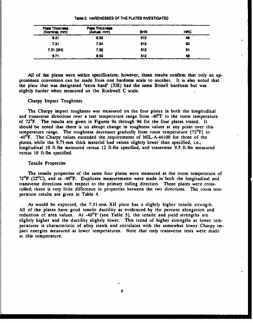
Table 3. HARDNESSES OF THE PLATES INVESTIGATED
Plate Thicknme PlE, Thickness(Nominal, mm) (Actual. mm) BHN HRC
6.31 6,50 512 48
7.31 7.24 512 50
7.31 (X0) 7.52 512 51
9.71 9.50 512 48
All of the plates were within specification; however, these results confirm that only an ap-proximate conversion can be made from one hardness scale to another. It is also noted thatthe plate that was designated 'extra hard' (XH) had the same Brinell hardness but wasslightly harder when measured on the Rockwell C scale.
Charpy Impact Toughness
The Charpy impact toughness was measured on the four plates in both the longitudinaland transverse directions over a test temperature range from -40OF to the room temperatureof 720F. The results are given in Figures 9a through 9d for the four plates tested. Itshould be noted that there is no abrupt change in toughness values at any point over thistemperature range. The toughness decreases gradually from room temperature (72 0 F) to-40 F. The Charpy values exceeded the requirements of MIL-A-46100 for three of theplates, while the 9.71-mm thick material had values slightly lower than specified; i.e.,longitudinal 10 ft-lbs measured versus 12 ft-lbs specified, and transverse 9.5 ft-lbs measuredversus 10 ft-lbs specified.
Tensile Properties
The tensile properties of the same four plates were measured at the room temperature of720F (220C), and at -400F. Duplicate measurements were made in both the longitudinal andtransverse directions with respect to the primary rolling direction. These plates were cross-rolled; there is very little difference in properties between the two directions. The room tem-perature results are given in Table 4.
As would be expected, the 7.31-mm XH plate has a slightly higher tensile strength.All of the plates have good tensile ductility as evidenced by the percent elongation andreduction of area values. At -40OF (see Table 5), the tensile and yield strengths areslightly higher and the ductility slightly lower. This trend of higher strengths at lower tem-peratures is characteristic of alloy steels and correlates with the somewhat lower Charpy im-pact energies measured at lower temperatures. Note that only transverse tests were madeat this temperature.
6

TaOle 4. TENSILE PROPERTIES OF HIGH HARD ARMOR AT ROOM TEMPERATURE
UTS 0.2% YS Elon. RASpecimen (ksi) (k*a) (%) (N)
6.31 mm LT 252.2 202.7 10.4 44.5
6.31 mm LT 251.6 206.6 10.2 42-6
6.31 mm TL 249.7 200.8 10.5 44.2
6.31 mm TL 244.5 201.1 10.1 43.2
7.31 mm LT 250.2 209.3 10.0 46.1
7.31 mm LT 253.4 205.6 11.0 45.2
7.31 mm TL 254.7 206.7 10.3 4&0
7.31 mm TL 251.1 207.6 - 9.4 43.1
7.31 mm XH LT 265.8 207.0 9.8 41.5
7.31 mm XH LT 263.7 206.9 10.0 42.1
7.31 mm XH TL 266.4 209.5 .11.3 36.1
7.31 mm XH TL 263.2 207.2 9.2 39.7
9.71 mm LT 250.0 197.7 12.0 48.89.71 mm LT 248.2 196.1 10.1 41.7
9.71 m TL 249.7 204.1 9.0 48.4
9.71 mm TL 255.0 205.3 10.5 33.6
NOTE: LT- LongiudinalTL = Transverse
TaOle 5. TENSILE PROPERTIES OF HIGH HARD ARMOR AT -40*F
UTS 0.2% YS Elon. RA
Specimen (kso) (khi) (%) (%)
6.31 mm TL 235.7 193.3 9.1 54.2
6.31 mm TL 255.0 209.9 11.2 50.1
7.31 mm TL 257.7 210.3 9.7 51.5
7.31 mm"TL 258.5 209.4 9.7 51.2
7.31 mm XH TI 266.5 205.8 9.4 48.3
7.31 mm XH TL 266.0 205.3 10.2 47.9
9.71 mm TL 263.6 213.0 9.9 43.9
9.71 mm TL 263.0 219.1 9.7 47.1
NOTE: TL = Transverse
7
Ballistic Properties
7.62-mm M1943 Ball
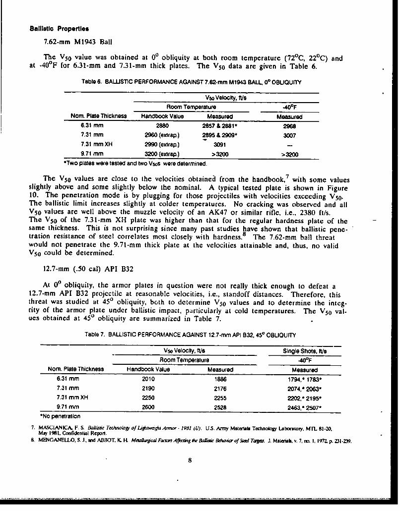
The V50 value was obtained at 00 obliquity at both room temperature (72 0 C, 220 C) andat -40OF for 6.31-mm and 7.31-mm thick plates. The V50 data are given in Table 6.
Table 6. BALLST1C PERFORMANCE AGAINST 7.62.mm M1943 BALL, 00 OBUQUITY
V50 Velocity, tesRoom Temperature -400F
Nom. Plate Thickness Handbook Value Measured Measured6.31 mm 2880 2857 & 2881' 29687.31 mm 2960 (extrap.) 2895 & 2909* 30077.31 mm XH 2990 (extrap.) 3091 -9.71 mm 3200 (extrap.) >3200 >3200
*Two plates were tested and two Vsos were determined.
The V50 values are close to the velocities obtainea from the handbook, 7 with some valuesslightly above and some slightly below the nominal. A typical tested plate is shown in Figure10. The penetration mode is by plugging for those projectiles with velocities exceeding VS0 .The ballistic limit increases slightly at colder temperatures. No cracking was observed and allV5 0 values are well above the muzzle velocity of an AK47 or similar rifle, i.e., 2380 ft/s.The V5 0 of the 7.31-rmm XH plate was higher than that for the regular hardness plate of thesame thickness. This is not surprising since many past studies have shown that ballistic pene-tration resistance of steel correlates most closely with hardness. 8 The 7.62-mm ball threatwould not penetrate the 9.71-mm thick plate at the velocities attainable and, thus, no validV5 0 could be determined.
12.7-mm (.50 cal) API B32
At 00 obliquity, the armor plates in question were not really thick enough to defeat a12.7-mm API B32 projectile at reasonable velocities, i.e., standoff distances. Therefore, thisthreat was studied at 450 obliquity, both to determine V5 0 values and to determine the integ-rity of the armor plate under ballistic impact, particularly at cold temperatures. The V50 val-ues obtained at 450 obliquity are summarized in Table 7.
Table 7. BALLISTIC PERFORMANCE AGAINST 12.7-mm API B32, 450 OBLIQUITY
Vs0 Velocity. ft/s Single Shots, WeRoom Temperature .40°F
Nom. Plate Thickness Handbook Value Measured Measured6.31 mm 2010 1886 1794.* 1783'7.31 mm 2190 2176 2074,*2063*7.31 mm XH 2250 2255 2202, 2195'9.71 mm 2600 2528 2463,* 2507'
*No penetration
7. MASCIANICA, F. S. Bafi¢ T,ý iechlo, of LigrwmdjiAnrmr. 1981 (U). U.S. Army Materab Technology Labortory, MNFL 81.20,May 1981, Confidenmial Repon.
8. MENGANELLO, S. J., and ABBOT, K. H MewhrucalFaariaAffeciig Ae 6ia WdzimaofSied Tawjm. J. Materials, v. 7. no 1, 197Z, p. 231.239.
8
At -40°F single shots were fired at velocities just below the room temperature V50 to de-termine if any of the plates exhibited a propensity to crack at low temperatures. No penetra-tion occurred for any of the shots. No cracking was observed under any conditions for the12.7-mm (.50 cal) API B32 threat.
20-mm Proof Round
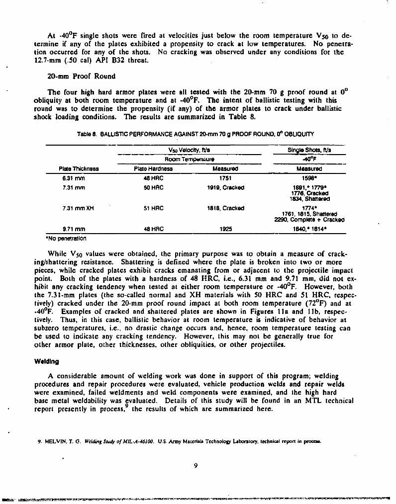
The four high hard armor plates were all tested with the 20-mm 70 g proof round at 00obliquity at both room temperature and at -400 F. The intent of ballistic testing with thisround was to determine the propensity (if any) of the armor plates to crack under ballisticshock loading conditions. The results are summarized in Table 8.
Table 8. BALUSTIC PERFORMANCE AGAINST 20-mm 70 g PROOF ROUND, 0p OBUQUITY
Vs0 Velocity, ft/s Single Shots. f/sRoom Tempbraure -40OF
Plate Thickness Plato Hardness Measured Measured
6.31 mm 48 HRC 1751 1596'7.31 mm 50 HRC 1919, Cracked 1691, 1779'
1776, Cracked1834. Shattered
7.31 mm XH 51 HRC 1818, Cracked 1774'1761, 1815, Shatlered
2290, Complete + Cracked
9.71 mm 48 HRC 1925 1840.' 1814'
*No penetration
While V5 0 values were obtained, the primary purpose was to obtain a measure of crack-ing/shattering resistance. Shattering is defined where the plate is broken into two or morepieces, while cracked plates exhibit cracks emanating from or adjacent to the projectile impactpoint. Both of the plates with a hardness of 48 HRC, i.e., 6.31 mm and 9.71 mm, did not ex-hibit any cracking tendency when tested at either room temperature or -40°F. However, boththe 7.31-mm plates (the so-called normal and XH materials with 50 HRC and 51 HRC, respec-tively) cracked under the 20-mm proof round impact at both room temperature (72 0 F) and at.400F. Examples of cracked and shattered plates are shown in Figures Ila and Ilb, respec-tively. Thus, in this case, ballistic behavior at room temperature is indicative of behavior atsubzero temperatures, i.e., no drastic change occurs and, hence, room temperature testing canbe used to indicate any cracking tendency. However, this may not be generally true forother armor plate, other thicknesses, other obliquities, or other projectiles.
Welding
A considerable amount of welding work was done in support of this program; weldingprocedures and repair procedures were evaluated, vehicle production welds and repair weldswere examined, failed weldments and weld components were examined, and the high hardbase metal weldability was evaluated. Details of this study will be found in an MTL technicalreport presently in process,9 the results of which are summarized here.
9. MELVIN, T. 0. Welding Sn# of MIL.A-46100. U.S. Army Malerials Technology Laboratory, technical repel in procrt.
9
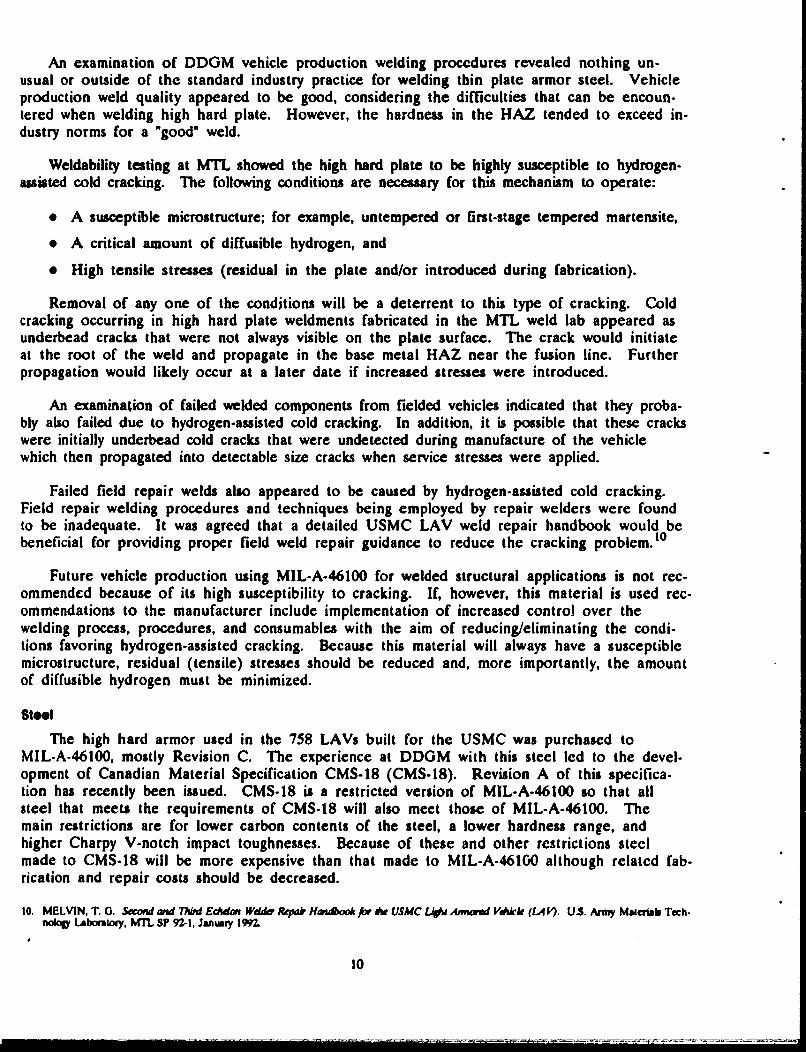
An examination of DDGM vehicle production welding procedures revealed nothing un-usual or outside of the standard industry practice for welding thin plate armor steel. Vehicleproduction weld quality appeared to be good, considering the difficulties that can be encoun-tered when welding high hard plate. However, the hardness in the HAZ tended to exceed in-dustry norms for a "good" weld.
Weldability testing at MTL showed the high hard plate to be highly susceptible to hydrogen-assisted cold cracking. The following conditions are necessary for this mechanism to operate:
"* A susceptible microstructure; for example, untempered or first-stage tempered martensite,
"* A critical amount of diffusible hydrogen, and
"* High tensile stresses (residual in the plate and/or introduced during fabrication).
Removal of any one of the conditions will be a deterrent to this type of cracking. Coldcracking occurring in high hard plate weldments fabricated in the MTL weld lab appeared asunderbead cracks that were not always visible on the plate surface. The crack would initiateat the root of the weld and propagate in the base metal HAZ near the fusion line. Furtherpropagation would likely occur at a later date if increased stresses were introduced.
An examination of failed welded components from fielded vehicles indicated that they proba-bly also failed due to hydrogen-assisted cold cracking. In addition, it is possible that these crackswere initially underbead cold cracks that were undetected during manufacture of the vehiclewhich then propagated into detectable size cracks when service stresses were applied.
Failed field repair welds also appeared to be caused by hydrogen-assisted cold cracking.Field repair welding procedures and techniques being employed by repair welders were foundto be inadequate. It was agreed that a detailed USMC LAV weld repair handbook would bebeneficial for providing proper field weld repair guidance to reduce the cracking problem. 10
Future vehicle production using MIL-A-46100 for welded structural applications is not rec-ommended because of its high susceptibility to cracking. If, however, this material is used rec-ommendations to the manufacturer include implementation of increased control over thewelding process, procedures, and consumables with the aim of reducing/eliminating the condi-tions favoring hydrogen-assisted cracking. Because this material will always have a susceptiblemicrostructure, residual (tensile) stresses should be reduced and, more importantly, the amountof diffusible hydrogen must be minimized.
Steel
The high hard armor used in the 758 LAVs built for the USMC was purchased toMIL-A-46100, mostly Revision C. The experience at DDGM with this steel led to the devel-opment of Canadian Material Specification CMS-18 (CMS-18). Revision A of this specifica-tion has recently been issued. CMS-18 is a restricted version of MIL.A-46100 so that allsteel that meets the requirements of CMS-18 will also meet those of MIL-A-46100. Themain restrictions are for lower carbon contents of the steel, a lower hardness range, andhigher Charpy V-notch impact toughnesses. Because of these and other restrictions steclmade to CMS-18 will be more expensive than that made to MIL-A-46100 although related fab-rication and repair costs should be decreased.
10. MELVIN, T. 0. Second and ThAd Edc•don Wddn, Repair HmdA for de USMC LJAW Ammored Vdhkk (LA/&I. US. Army Malcrob Tech-noagy Labortory, MT SP 92-1, January 1992.
10

Steel Producers
There was a long history of steel procurement for the USMC vehicles with several steelproducers and heat treaters involved. For the final production period Lukens Steel Companywas the principal supplier. As is the case with any material, there are learning curves associ-ated with producing and welding this material. Apparently, as experience was gained at Lu-kens and DDGM with light gage high hard steels, the cracking problems decreased markedly.
Lukens Steel Company
At present, Lukens is the only North American producer that is supplying hard steelarmor plate. Lukens has both continuous (strand) casting and ingot casting capabilities usinga 165-ton electric furnace. Continuous casting is a considerably cheaper process because ofthe higher product-yields and is being increasingly used worldwide. It is by far the dominantprocess today. In 1987, 59% of raw steel output in the USA was continuously cast comparadwith 7% in 1973 and 20% in 1980. Developed countries have even higher percentages with80% in the European Economic Community and 93% in Japan continuously cast. A full 75%of all steel in the western world was continuously cast in 1987 and the numbers are evenhigher today. Lukens' caster produces slabs 9" thick x 96" wide. For other processing equip.ment improvements, Lukens has recently installed a ladle degassing unit that will improve qual-ity and decrease steelmaking costs. This tank degasser will also ensure low hydrogen levels inthe steel.
After some cross-rolling of the continuously cast (or ingot) slab, the steel is hot rolled tofinal gage on plate mills. Heat treatment is accomplished in-house on a continuous horizontalroller quench line. After austenitizing for about 20 minutes, the steel is progressively spray-water quenched from both sides while slowly passing through rolls to maintain flatness. Thequenched plate continues down the line and into the tempering furnace.
Lukens has now accepted CMS-18A and has been qualified by DDGM to provide steel tothis %pecification. Lukens also supplies MIL-A-46100 steel for other applications such as theMI tank program, and it would be very desirable from their viewpoint to be able to use theproduct from one heat for both LAV and MI plate.
Creusot-Marrel
This French company was the first to accept CMS-18 and supplied high hard plates forcertain LAV components for the Canadian buy, e.g., hatch covers, etc. Creusot-Marrel castsall of their steel into relatively small ingots. After austenitizing, the plates are clamped in aplaten system and quenched into a vertical oil bath that reportedly minimizes residual stressand plate distortion. Both the quenching and tempering are batch operations. The batchtempering of a stack of plates may cause problems in the uniformity of the time each plate"sees" the required tempering temperature. A D650 (Exploit-Ition of Foreign Materiel) pro-gram is presently underway at MTL to more fully define the benefits (if any) of the Frenchsteel. Creusot-Marrel also has a laser cutting system that as far as is known is unparalleledin the United States. This system can be used to cut plates to any shape with excellentedges.
Since the steel is made in smaller heats (compared with Lukens), is ingot cast, and un-
dergoes some batch processing, it probably will be more expensive.
11
Carbon Content
The ASTM requirement for chemical composition of steels with a ladle analysis of up to0.30 wt% carbon allows t 0.02 wt% carbon in a product analysis. However, CMS-18, CMS-18A, and MIL-A-46100 all specify product analysis. To meet all the prodact mechanical andballistic property requirements of CMS-18 the steel producer realistically must make the melt(ladle analyses) with 0.29 ± 0.01 wt% C. If the carbon is any lower, the hardness and ballis-tics will not be met, and if it is any higher toughness will be difficult to attain (and weldabil-ity impaired). This is a very narrow carbon range and only a few years ago could not beconsistently met. It is only with the advent of new ladle metallurgy processing that steelswith this narrow carbon range can be practically produced.
Tempering
"High hard armor is tempered between 350°F and 450 0 F. The minimum temperature of350°F was introduced into MIL-A-4600 in Revision C (13 June 1983) after some plates thatwere tempered at much lower temperatures experienced cracking problems. Above -450 0 F,alloy steels exhibit temper embrittlement with a lowering of toughness values. Therefore, met-allurgically, this is a good range.
SUMMARY AND CONCLUSIONS
Cracking
It is concluded that much of the cracking. occurring in LAVs that initiated at free cutedges may be attributed to environmentally-assisted cracking where there was some untem-pered martensite present. Cracks that initiated at welds were attributed to a number of possi-ble causes: stress-corrosion cracking, underbead cold cracks undetected during vehiclemanufacture that propagated to detectable sizes, hydrogen-assisted cold cracking due to im-proper field repair techniques, and cracks resulting from extremely harsh vehicle use.
Mechicjal Propert!n
The tensile properties, Charpy V-notch impact toughness and hardness of four plates of vary-ing thickness of MIL-A-46100 were measured at room temperature and at -400F (-40 0C). Thehardnesses of the four plates were 48, 48, 50, and 51 HRC. The mechanical properties mea-sured were all typical of an alloy steel of about 50 HRC. At room temperature, tensilestrengths were about 250 ksi to 260 ksi, yield strengths 200 ksi to 210 ksi (0.2% offset). 10%elongation, and 40% to 50% reduction of area. At -40°F both strength and ductility were sim-ilar to the values obtained at room temperature. The Charpy impact values decreased slightly asthe test temperature was lowered from the room temperature of 72OF to -400 F. All values ex-ceeded the requirements of MIL-A-46100, except the 9.71-mm plate had slightly lower than speci-fied Charpy impact energy at -400 F. Steels of the same hardness are used in many criticalstructural applications. For example, highly stressed aircraft landing gear components are almostinvariably made of 30)M, a steel of somewhat higher hardness and similar ductility and toughness.
Ballistic Properties -I
The ballistic properties of the same four plates were studied with 7.62-mm M1943 ball,12.7-mm (.50 cal) API B32 and 20-mm 70 g proof round threats. These ballistic properties weremeasured from room temperature (720F) to -40 0 F and at the various target obliquities up to 45'.
12
The V50 values were consistent with handbook values7 in those cases where it was possi-ble to match plate thickness, threat, and obliquity. One of the objectives of the ballistic test-ing was to determine the propensity of this steel to crack at low temperatures under heavyloading. The blunt-nosed proof round was used for this purpose. The only cracking ob-served occurred for the two plates having higher hardnesses. Both plates with a hardness of48 HRC did not exhibit any cracking under any of the conditions tested.
RECOMMENDATIONS
Since plate edge cutting is so important it is recommended that laser cutting be consid-ered. This procedure would reduce the thickness of the HAZ of cutting to a level thatwould obviate edge grinding.
Underwater plasma cutting of high hardness armor steel is not recommended, but if it re-mains the standard procedure, then edge grinding should be done immediately (less than onehour) after cutting. Delays could cause cracks to initiate and grow to a size that would notbe subsequently removable. It is imperative that careful grinding to remove any fresh, brittle,untempered martensite must be accomplished without introducing excessive heat.
The ballistic study has shown that steel with higher hardness (and carbon content) ismore prone to cracking. The Charpy V-notch impact toughness is also improved at lowerhardnesses. Thus, this study has confirmed experience at DDGM that higher hardness(i.e., higher carbon steel) should be avoided. It is recommended that the Canadian MaterialSpecification, CMS-18, be employed for future purchases of high hard armor steel for theLAV. The lower carbon content and restricted hardness range specified in CMS-18 is a stepin the right direction, although it is likely that further modifications will occur in the futureas experience is gained. Because of this tighter specification, initial cost of the steel will behigher, but lifetime vehicle costs should be lower.
MIL-A-46100 was originally developed as an appliqui armor and was never intended tobe used in a welded structural application. It should be stressed that as long as this or otherstage-one tempered material is used on the LAV, weldment cracking will never be completelyeliminated. However, recommendations can be made to help minimize the cracking problem.Additional welding process and consumable controls should be implemented for future vehicleproduction to further reduce diffusible hydrogen levels and residual stresses in the weld area.It should also be noted here that preheat should be considered for the welding of high hardplate; even if used only for moisture removal from the weld joint, preheat would be benefi-cial. Furthermore, it is recommended that austenitic stainless steel weld wire be investigatedas austenitic welds are much less susceptible to hydrogen-related cracking. This is standardpractice in Europe, i.e., a 0.42 wt% carbon armor steel on the German Leopard tank iswelded with stainless steel wire. However, stainless steel filler metal has its own shortcomingsand must be thoroughly investigated and tested prior to implementation.
ACKNOWLEDGMENTS
The authors wish to thank COL. Re,:d T. Bolick., LAV-PM, and Mr. Ben Nelsen, LAV-PMO, for their support and guidance during the performance of this study.
Individuals within MTL who have contributed significantly to this program includeMr. Gene DeLuca, Dr. George Bishop, and Messrs. Wayne Bethoney, Bill Crenshaw,Bob Pasternak, and Jim Catalano.
13
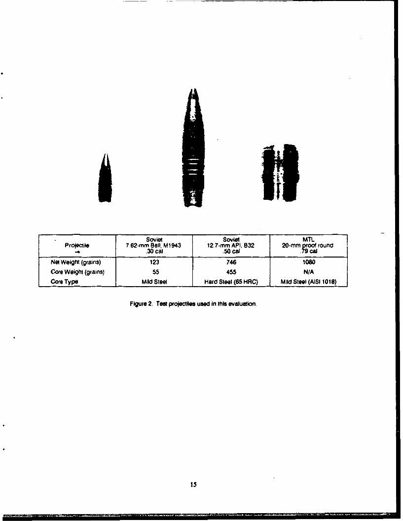
Soviet Soviet MiTProjectile 7.62-mm Sell, M1943 12.7-mm API. 832 20-mm roof on
-b.30 cal .50 call
Net Weight (grains) 123 746 1080Core Weight (grains) 55 455 N/ACore Type Mild Steel Hard Steel (65 HRC) Mild Steel (AISI 1018)
Figure 2. Test projectiles used In this evaluation.
15
(a)
""Fgr 3. A Cr. .
• ,~. ,-
•*-,,,.
116
4 ________'•
I.. - ,-,,,
"(,) (C . ... .
Fue3()Cakdrwdo,(, p•,mirgaho deo craced: .dorsowreLno uie n ee wesle("h ra) i C ige anfclo iwo b
,. z,, [•° "# i16

20 ~ ~
I Cracked ;oor
C
.C 10
0~ OLT~. 5- - _ _ -
C6 0 TL
0
-50 -40 -30 -20 -10 0 10 20 30
Test Temperature (OC)
Figure 4. CVN energy (3/4-size specimens) versustest temperature; cracked door.
Figure S. Optical micrograph of edge of cracked reardoor showing docarbUrization and banding. Mag. SOX
17
MODEL .AUTHORDDGM S/N ZAl,. i/z REPORT DATE o7/,1-/',UI O.C SIN ,zlzsml HULL CVEH MILES L.. HATCH (zVEH HOURS . DOOR 1VEH LOC'N I Z 6,,4,Yv V r.UNIT ___,__,,__
STORYBOARD"o CRACK LENGTH____ oo ________._*START/STOP POINTn. -*COMMENTS //xtsZ ,_._•
Figure 6. Fild service rep• rt for cracked htc.
18
(a)stainl
high hard artnor
E
()7.5x (c) 50
Figure 7 (a) Cracked turret hatc 1- cover. (tb) Macrograph of edge of cracked hatch cover, and (c) Optical micrograph of HAZ
19
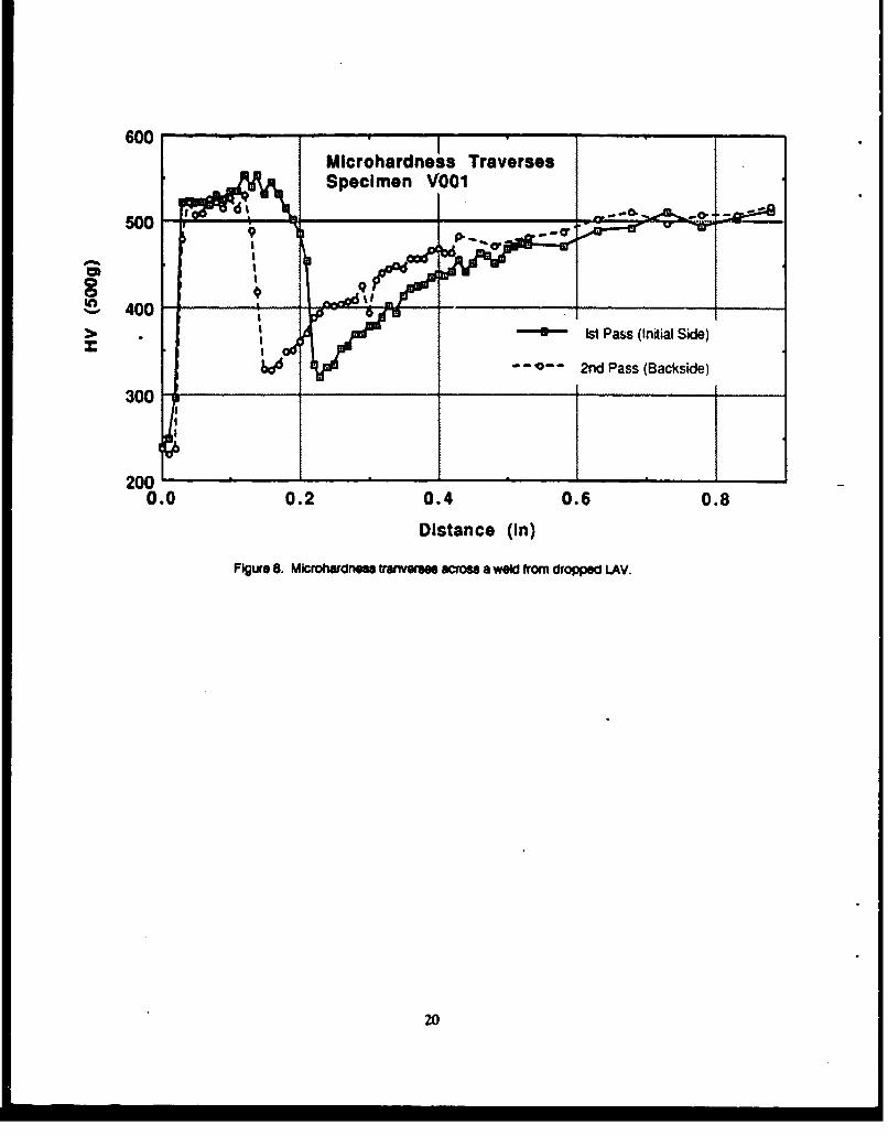
600Mlcrohardne ss TraversesSpecimen VO01
Soo
0 400 0> -- Ist Pass (Initial Side)
-- 0-- 2nd Pass (Backside)
300
200
0.0 0.2 0.4 0.6 0.8
Distance (In)
FIgure 8. Microwardnes tramnees across a weld from dropped LAV.
20
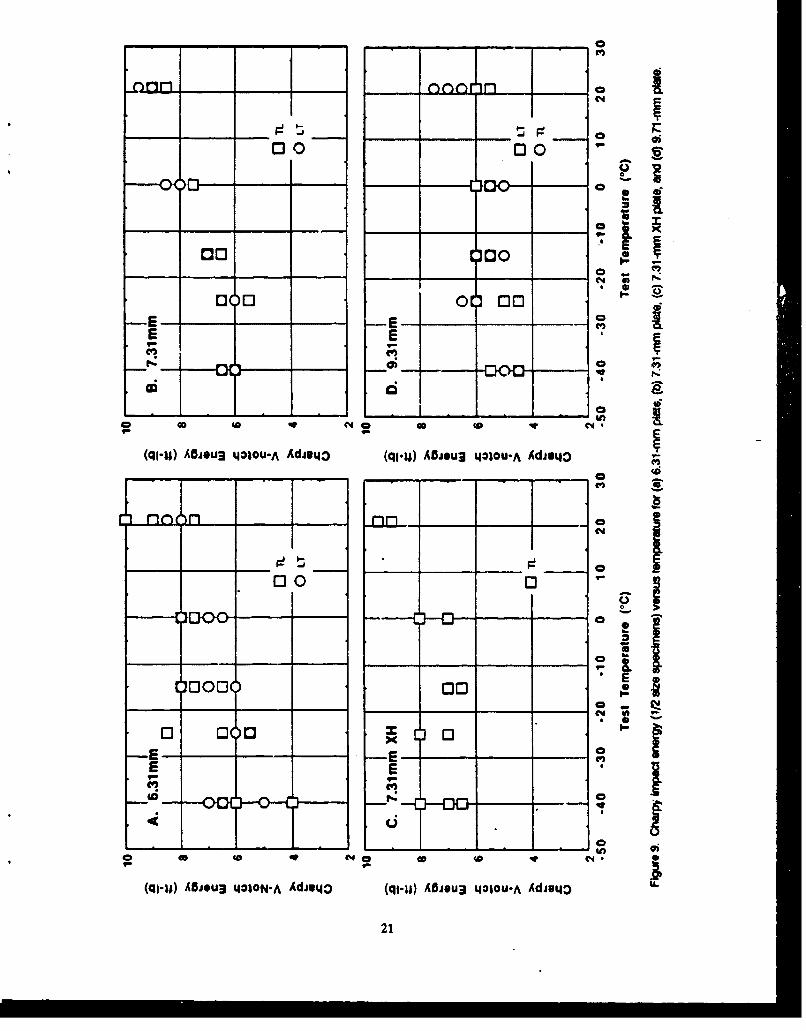
0
nonrinfn n
00 0
110 DoN 40
030 0_ 00__ __
-E -E-
E E2C
f- - - -
cc4 40 N4 40 co 0 V.
(qi-U) ABiOu3 i4o1ou-A AdJui43 (ql-14) A5jeu3 tI*Iou.A Adiu43J
00 0
_ -v
0 00_ 00 _
Cý
x0
40 co C4
(qg-U) AflJOU3 4010N-A Av4D (qI-tu) AOJOu3 14*I0U-A AdisijO
21
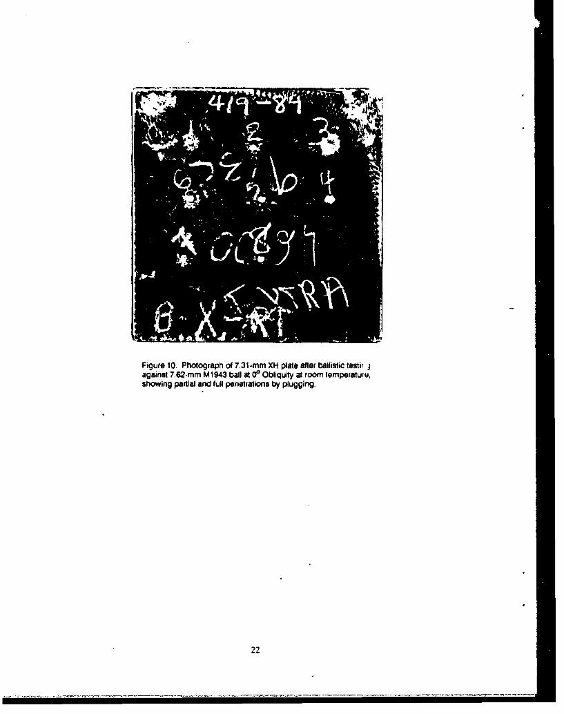
Figure 10. Photograph of 7.31-mm XH plate after ballistic lestir jagainst 7.62-mm M1943 ball at 00 Obliquity at room temperaturu,showing partial and full penetrations by plugging.
22
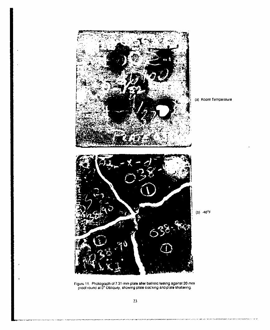
-.,1 5(b) -40OF
Figur¶ 11. Photograph of 7.31 -mm plate after ballistic testing against 20-mmproof round at 0' Obliquily, showing plate cracking and plate shattering.
23

DISTRIBUTION LIST
No. ofCopies To
1 Office of the Under Secretary of Defense for Research and Engineering, The Pentagon, Washington, DC 20301
Commander, U.S. Army Laboratory Command, 2800 Powder Mill Road, Adelphi, MD 20783-11451 ATTN: AMSLC-IM-TL1 AMSLC-CT
Commander, Defense Technical Information Center, Cameron Station, Building 5, 5010 Duke StreetAlexandria. VA 22304-6145
2 ATTN: DTIC-FDAC
1 MIACINDAS, Purdue University, 2595 Yeager Road, West Lafayette, IN 47905
Commander, Army Research Office, P.O. Box 12211, Research Triangle Perk, NC 27709.22111 ATTN: Information Processing Office
Commander, U.S. Army Materiel Command, 5001 Eisenhower Avenue, Alexandria, VA 223331 ATTN: AMCSCI
Commander, U.S. Army Materiel Systems Analysis Activity, Aberdeen froving Ground, MD 210051 ATTN: AMXSY-MP, H. Cohen
Commander, U.S. Army Missile Command, Redstone Scientific Information Center,Redstone Arsenal, AL 35898-5241ATTN: AMSMI-RD-CS-R/Doc
1 AMSMI-RLM
Commander, U.S. Army Armament, Munitions and Chem;cal Command, Dover, NJ 078012 ATTN: Technical Library
Commander, U.S. Army Natick Research, Development and Engineering Conter,Natick, MA 01760-5010
1 ATTN: Technical Library
Commander, U.S. Army Satellite Communications Agency, Fort Monmouth, NJ 077031 ATTN; Technical Document Center
Commander, U.S. Army Tank-Automotive Command, Warren, MI 48397-50001 ATTN: AMSTA-ZSK2 AMSTA-TSL Technical Library1 AMCPM-LAV-P1 AMCPM-LAV, COL K. Chandler5 AMCPM-LAV-E1 AMCPM-LAV-L
Commander, White Sands Missile Range, NM 880021 ATTN: STEWS-WS-VT
President, Airborne, Electronics and Special Warfare Board, Fort Bragg, NC 283071 ATTN: Library
Director, U.S. Army Ballistic Research Laboratory, Aberdeen Proving Ground, MD 210051 ATTN: SLCBR-TSB-S (STINFO)
Commander, Dugway Proving Ground, UT 840221 ATTN: Technical Library, Technical Information Division
Commander, Harry Diamond Laboratories, 2800 Powder Mill Road, Adelphi, MD 207831 ATTN: Technical Information Offic,
Director, Banet Weapons Laboratory, LCWSL USA AMCCOM, Watervllet, NY 121891 ATTN: AMSMC-LCB-TLI AMSMC-LCB-R1 AMSMC-LCB-RM1 AMSMC-LCB-RP
Commander, U.S. Army Foreign Science and Technology Center, 220 7th Street, N.E.,Charlottesville, VA 22901-5396
3 ATTN: AIFRTC, Applied Technologies Branch, Gerald Schlesinger
Commander, U.S. Army Aeromedical Research Unit, P.O. Box 677, Fort Rucker, AL 363601 ATTN: Technicpl Library
No. ofCopies To
Commander, U.S. Foreign Science and Technology Center, 220 7th Street, N.E., Charlottesville, VA 22901-53961 ATTN: AIFRTC, Applied Technologies Branch, Gerald Schlesinger
Commander, U.S. Army Aviation Systems Command, Aviation Research and Technology Activity,Aviation Applied Technology Directorate, Fort Eustis, VA 23604-5577
1 ATTN: SAVDL-E-MOS
U.S. Army Aviation Training Library, Fort Rucker, AL 363601 ATTN: Building 5906.6907
Commander, U.S. Army Agency for Aviation Safety, Fort Rucker, AL 363621 ATTN: Technical Library
Commander, USACDC Air Defense Agency, Fort Bliss, TX 799161 ATTN: Technical Ubrary
Commander, Clarke Engineer School Library, 3202 Nebraska Ave., N, Ft. Leonard Wood, MO 66473-50001 ATTN: Library
Commander, U.S. Army Engineer Waterways Experiment Station, P.O. Box 631, Vicksburg, MS 391801 ATTN: Research Center Library
Commandant, US. Army Quartermaster School, Fort Lee, VA 238011 ATTN: Quartermaster School Library
Naval Research Laboratory, Washington, DC 203751 ATTN: Code 58302 Dr. G. R. Yoder - Code 6314
Chief of Naval Research, Arlington, VA 222171 ATTN: Code 471
1 Edward J. Morrissey, WRDC/MLTE, Wright-Patterson Air Force Base, OH 45433-6523
Commander, U.S. Air Force Wright Research & Development Center,Wright-Patterson Air Force Base, OH 45433-6523
1 ATTN: WRDC/MLLP, M. Fomey, Jr.1 WRDC/MLBC, Mr. Stanley Schulman
NASA - Marshall Space Flight Center, MSFC, AL 358121 ATTN: Mr. Paul Schuerer/EH01
U.S. Department of Commerce, National Institute of Standards and Technology, Gaitherburg, MD 208991 ATTN: Stephen M. Hsu, Chief, Ceramics Division, Institute for Materials Science and Engineering1 Committee on Marine Structures, Marine Board, National Research Council, 2101 Constitution Avenue, N.W.,
Washington, DC 20418
1 Librarian, Materials Sciences Corporation, 930 Harvest Drive, Suite 300, Blue Bell, PA 19422
1 Charles Stark Draper Laboratory, 68 Albany Street, Cambridge, MA 02139
Wyman-Gordon Company, Worcester, MA 016011 ATTN: Technical Library
General Dynamics, Convair Aerospace Division P.O. Box 748, Forth Worth, TX 761011 ATTN: Mfg. Engineering Technical Library
1 Mr. Karl S. Morgenroth, Progran. Manager, Light Armored Vehicles, Canadian Commercial Corporation,Box 5160, London, Ontario N6A 4N5
5 Diesel Division, General Motors of Canada, LTD, Box 5160, London, Ontario N6A 4N6Director, U.S. Army Materials Technology Laboratory, Watertown, MA 02172-0001
2 ATTN: SLCMT-TML4 Authors
a ? I
* IF
,+tA' : II
ji 4 Ii
i iiiiI!ji xli;
P1l ji il'jI-- -- -- -- -- -- -- ----- -------- -- - ----------------------------------------- --
f3 A I Ac
I oll