Embed Size (px)
Citation preview


This work was performed by the J c t Propulsion Laboratory , California Institute of Technology , under NASA Cont r act NAS7-100 for the U. S . Ene r gy Research and Deve l opmen t Adminis tration , Division of Solar Energy .
The JPL Low-cost Silicon Solar Array Project is funded by ERDA a nd fo rms part of Lhc ERDA Pho tovoltai c Co nversion Program to initiate n maj or e[[o r t Loward the development of low-cost solar a rrays .

LOW-COST SILICON SOLAR ARRAY PROJECT
5101-20
TEST PROGRAM ON LOW-COST CONNECTOR
FOR SOLAR-ARRAY MODULES
February 28, 1977
A.H. Cantu
Approved by:
LS~A Engineering Manager
JET PROPULSION LABORATORY
CALIFORNIA INSTITUTE OF TECHNOLOGY
PASADENA, CALIFORNIA

5101-20
CONTENTS
I. INTRODUCTION------------------------------------------------------ 1-1
II. HARDWARE TESTED--------------------------------------------------- 2-1
A. PART DESCRIPTION-------------------------------------------- 2-1
B. TEST SPECIMENS---------------------------------------------- 2-2
III. DESCRIPTION OF TESTING------------------------------------------~- 3-1
A. PROGRAM----------------------------------------------------- 3-1
B. TEST CHARACTERISTICS---------------------------------------- 3-1
IV. ANALYSIS OF TEST RESULTS------------------------------------------ 4-1
A. TESTS PERFORMED AT DELSEN LABS------------------------------ 4-1
B. JPL TESTS--------------------------------------------------- 4-8
V. CONCLUSIONS------------------------------------------------------- 5-1
REFERENCES--------------------------------------------------------------- 6-1
Tables
1. Sample/Test Distribution------------------------------------------ 3-2
2. Minimum Insulation Resistance Reading (in ohms) After Environmental Exposure of Cannon Sure-Seal 2 and 3 Contact Connectors (at 500 Vdc) ----------------------------------- 4-2
3. Maximum Contact Resistance Increase (in ohms) After Environmental Exposure-------------------------------------------- 4-3
4. Results of Tests Performed at JPL on Groups I, II, III, and V After Environmental Exposure at Delsen Labs------------------------------------------------------- 4-7
5. Group IV Connector Contact Test - 2-Conductor Black (Nitrile Rubber)-------------------------------------------------- 4-9
iii

5101-20
6. Group IV Connector Contact Test - 3-Conductor Black (Nitrile Rubber)------------------------------------------------- 4-10
7. Group IV Connector Contact Test - 3-Conductor Gray (EPDM) -------- 4-11
8. High Voltage Breakdown Test, Two Specimens From Groups I, II, III, and V Including all EPDM (SS3G) Connectors----------- 4-12
iv
5101-20
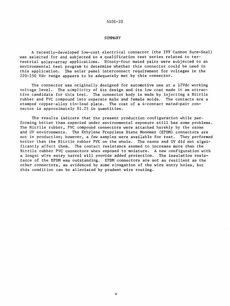
SUMMARY
A recently-developed low-cost electrical connector (the ITT Cannon Sure-Seal) was selected for and subjected to a qualification test series related toterrestrial solar-array applications. Ninety-four mated pairs were subjected to an environmental test program to determine whether this connector could be used in this application. The solar panel interconnect requirement for voltages in the 220-250 Vdc range appears to be adequately met by this connector.
The connector was originally designed for automotive use at a 12Vdc working voltage level. The simplicity of its design and its low cost made it an attractive candidate for this test. The connector body is made by injecting a Nitrile rubber and PVC compound into separate male and female molds. The contacts are a stamped copper-alloy tin-lead plate. The cost of a 4-contact mated-pair connector is approximately $1.25 in quantities.
The results indicate that the present production configuration while performing better than expected under environmental exposure still has some problems. The Nitrile rubber, PVC compound connectors were attacked harshly by the ozone and UV environments. The Ethylene Propylene Diene Monomer (EPDM) connectors are not in production; however, a few samples were available for test. They performed better than the Nitrile rubber PVC on the whole. The ozone and UV did not significantly affect them. The contact resistance seemed to increase more than the Nitrile rubber PVC connectors when exposed to moisture. A new configuration with a longer wire entry barrel will provide added protection. The insulation resistance of the EPDM was outstanding. EPDM connectors are not as resilient as the other connectors, as evidenced by some elongation of the wire entry holes, but this condition can be alleviated by prudent wire routing.
V

5101-20
SECTION I
INTRODUCTION
In support of cost reduction efforts associated with the development of low cost solar power generation, the Cabling Group was asked to select and evaluate electrical interconnect techniques for possible application with silicon solar cell hardware. The main driving force behind the program is reduction of present day production costs of generated power down to an affordable level, presently targeted at $.50 per watt. The logical starting point in this effort is the selection/development of reliable low cost components. To this end, a search was initiated in vendor catalogues and in cabling and connector manufacturing houses for existing designs which would fit our projected designs.
One company, ITT Cannon Electric, had recently won a competitive effort to design, and manufacture a low cost connector for use in the automotive industry. Cannon's Sure-Seal connector is presently in use on the automatic brake systems electrical circuits of large diesel trucks and busses. In this case, the electrical application is at 12 volts, and the advertised insulation resistance for the present production version of this connector is 100 megohms, measured at a low test voltage of 50 Vdc. While working voltages in the solar panel applications have not been specified, a 250-Vdc working voltage level is conceivable.
The overall simplicity of the design and construction combined with an attractive low cost made the Cannon Sure-Seal connector a highly viable candidate for use on the solar panel program provided it did well in a test program. This qualification test program was designed to verify physical and electrical characteristics that appeared to be inherent in a connector of such good simple design.
1-1

A. PART DESCRIPTION -
5101- 20
SECTION II
HARDWARE TESTED
The Cannon Sure-Seal ( Figure 1) was developed by the Cannon Company to meet a speci f i c requirement in the au t omotive field . The Sure-Seal connector was selected for this test because of its simplicity , low cost , and apparen t good environmental design . The complete connector consists of two one- piece molded bodies and contacts .
RalHd Indexing Spline
Connector Retaining Shoulder
Connector to Connector Deep Receue, Multiple Seals
Ralnd lndellln11 Rib
Boot 10 llodJ UulUple .....
'------OM,.._ lodf
RICIIIIHlocat .._ ______ Conhld
Multiple Ripple __ __. Wire Se1l1
1.---- (WI .. omitted for clartt,)
Figure 1 . Cannon Sure- Seal Connector
Boot to Cable Multiple Seal,
The fo l lowing standard data have been ext r acted f r om the manufact urer ' s brochure :
2-1

Materials and Finishes
Plug Receptacle Contacts
Elastomeric material Elastomeric material Copper alloy, tin-lead plate
Mechanical Data
Crimp Contacts
Contact Positions
Polarization
Contact Retention
Contact Insertion
Semi-automatic or hand crimpable.
2, 3, and 4
Stepped plane positive polarization and visual polarization.
8 lb minimum.
From rear with simple hand tool, or simultaneous insertion of multiple crimped contacts.
5101-20
Electrical Data
Contact Resistance
Current Rating
Insulation Resistance
Dielectric Withstanding Voltage
Wire Insulation Sealing Range
Accessories
Protective Seal Boot
10 Milliohms maximum.
15 amps continuous at 85°C
8 amps continuous at 105°C
100 Megohms minimum.
1,200 vac at sea level.
.100" minimum,
.147" maximum.
Seals cabled wire jackets to connector housing.
The data indicate that the connector can accomodate a· maximum wire insulation meter of .147". There are several insulating materials (nylon, teflon, etc.) that will easily permit a 12-gage wire to be used with these connectors.
B. TEST SPECIMENS
A total of 94 mated pairs of two-and three-contact connectors were tested, together with 50 pairs of bare contacts. The specimens were divided into the following groups in the quantity indicated for tests to be performed at Delsen Corporation Testing Laboratories Glendale, California, and (where noted) at JPL.
Graue SEecimen Breakdown Ref. Table
Group I 10 mated pair of two contact (SS2) See Tables 1, 2, 3, 4, and 8 10 mated pair of three contact (SS3)
Group II Same as Group 1 See Tables 1, 2, 3, 4, and 8
Group III Same as Group 1 See Tables 1, 2, 3, 4, and 8
2-2
Group
Group IV
Group V
Group VI
Note:
5101-20
Specimen Breakdown
See Below
Sarne as Group 1
50 mated pairs of bare contacts (with pigtails)
Ref. Table
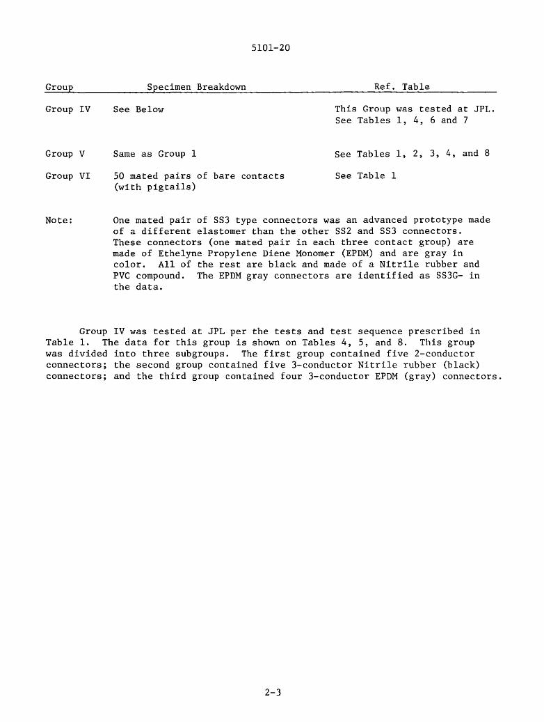
This Group was tested at JPL. See Tables 1, 4, 6 and 7
See Tables 1, 2, 3, 4, and 8
See Table 1
One mated pair of SS3 type connectors was an advanced prototype made of a different elastomer than the other SS2 and SS3 connectors. These connectors (one mated ~air in each three contact group) are made of Ethelyne Propylene Diene Monomer (EPDM) and are gray in color. All of the rest are black and made of a Nitrile rubber and PVC compound. The EPDM gray connectors are identified as SS3G- in the data.
Group IV was tested at JPL per the tests and test sequence prescribed in Table 1. The data for this group is shown on Tables 4, 5, and 8. This group was divided into three subgroups. The first group contained five 2-conductor connectors; the second group contained five 3-conductor Nitrile rubber (black) connectors; and the third group contained four 3-conductor EPDM (gray) connectors.
2-3

5101-20
SECTION III
DESCRIPTION OF TESTING
The qualification test was designed to represent the actual environments the connectors would be most likely to experience. The test sequence (See Table 1) was divided into two main areas of exposure. One was the effects of· only weather (humidity, salt spray, etc.) and the other was the possible physical damage from handling. All specimens, except Group IV and the bare contacts in Group VI, were submitted to both exposures.
A. PROGRAM
The connectors were divided into five groups as described above. Groups I, II, III and V were tested in the sequence shown in Table 1. The environmental testing on these groups was performed at Delsen Corporation Testing Laboratories in Glendale, California.
Tests at JPL were performed to determine the electrical properties of the connectors after subjecting them to physical tests only. Insulation Resistance tests were performed before and after the contact/connector retention and durability tests defined in subsequent paragraphs. Additionally, a 1500-Vac dielectric withstanding voltage was applied to all connectors. A visual inspection (6x microsc0p~) was performed before and after these tests. A final voltage breakdown test was performed wherein the voltage was increased in 500 volt increments, each step held for one minute, until breakdown occurred.
Tests Performed at Delsen Labs:
Temperature Cycling and Humidity
Salt Spray
Ozone and Ultra-Violet Exposure
Insulation Resistance at High Temperature
Insulation Resistance at Room Temperature prior to and after environmental exposure
B. TEST CHARACTERISTICS
Test Performed at JPL:
Insulation Resistance
Connector/Contact Retention/Durability
Final Connector/Contact Retention
Dielectric Withstanding Voltage
Visual
The following paragraphs briefly summarize the physical, environmental, and electrical tests.
3-1

w I
N
Group I (20 Units)
II (20 Units)
III (20 Units)
IV (14 Units)
V (20 Units)
Contacts (SO Mated Pairs)
Table 1.
NOTE: Shaded areas indicate tests performed at JPL.
Sample/Test Distribution
V,
1--' 0 1--' I
N 0
5101-20
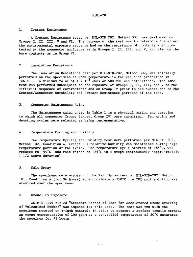
1. Contact Resistance
A Contact Resistance test, per MIL-STD 202, Method 307, was performed on Groups I, II, III, V and VI. The purpose of the test was to determine the effect the environmental exposure sequence had on the resistance of contacts when protected by the connector enclosure as in Groups I, II, III, and V, and also on the bare contacts as in Group VI.
2. Insulation Resistance
The Insulation Resistance test per MIL-STD-202, Method 302, was initially performed on the specimens at room temperature in the sequence prescribed in Table 1. A minimum value of 1 x 10⁸ ohms at 500 Vdc was established. The same test was performed subsequent to the exposure of Groups I, II, III, and V to the different sequence of environments and on Group IV prior to and subsequent to the Contact/Connector Durability and Contact Resistance portions of the test.
3. Connector Maintenance Aging
The Maintenance Aging entry in Table 1 is a physical mating and demating to which all connector Groups (except Group IV) were submitted. Ten mating and demating cycles were selected as being representative.
4. Temperature Cycling and Humidity
The Temperature Cycling and Humidity test were performed per MIL-STD-202, Method 102, Condition A, except 90% relative humidity was maintained during high temperature portion of the cycle. The temperature cycle started at +85°C, was reduced to -55°C, and then raised to +25°C in 4 steps continuously (approximately 1 1/2 hours duration).
5. Salt Spray
The specimens were exposed to the Salt Spray test of MIL-STD-202, Method 101, Condition A (for 96 hours) at approximately 350°C. A 20% salt solution was atomized over the specimens.
6. O~one, UV Exposure
ASTM D-1149 titled "Standard Method of Test for Accelerated Ozone Cracking of Vulcanized Rubber" was imposed for this test. The test was run with the specimens mounted on 4-inch mandrels in order to present a surface tensile strain. An ozone concentration of 100 pphm at a controlled temperature of 50°C saturated the specimen for 72 hours.
3-3
5101-20
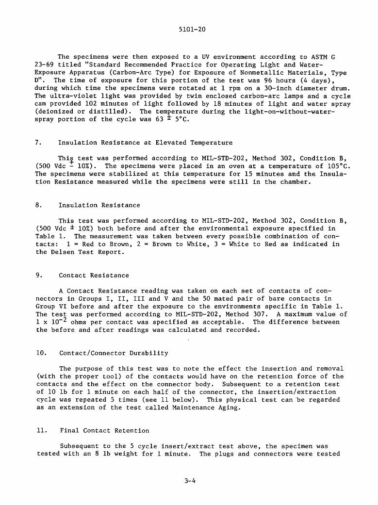
The specimens were then exposed to a UV environment according to ASTM G 23-69 titled "Standard Recommended Practice for Operating Light and WaterExposure Apparatus (Carbon-Arc Type) for Exposure of Nonmetallic Materials, Type D". The time of exposure for this portion of the test was 96 hours (4 days), during which time the specimens were rotated at 1 rpm on a 30-inch diameter drum. The ultra-violet light was provided by twin enclosed carbon-arc lamps and a cycle cam provided 102 minutes of light followed by 18 minutes of light and water spray (deionized or distilled). The temterature during the light-on-without-waterspray portion of the cycle was 63 - 5°C.
7. Insulation Resistance at Elevated Temperature
Thil test was performed according to MIL-STD-202, Method 302, Condition B, (500 Vdc - 10%). The specimens were placed in an oven at a temperature of 105°C. The specimens were stabilized at this temperature for 15 minutes and the Insulation Resistance measured while the specimens were still in the chamber.
8. Insulation Resistance
This test was performed according to MIL-STD-202, Method 302, Condition B, (500 Vdc ± 10%) both before and after the environmental exposure specified in Table 1. The measurement was taken between every possible combination of contacts: 1 = Red to Brown, 2 = Brown to White, 3 = White to Red as indicated in the Delsen Test Report.
9. Contact Resistance
A Contact Resistance reading was taken on each set of contacts of connectors in Groups I, II, III and V and the 50 mated pair of bare contacts in Group VI before and after the exposure to the environments specific in Table 1. The test was performed according to MIL-STD-202, Method 307. A maximum value of 1 x 10⁻² ohms per contact was specified as acceptable. The difference between the before and after readings was calculated and recorded.
10. Contact/Connector Durability
The purpose of this test was to note the effect the insertion and removal (with the proper tool) of the contacts would have on the retention force of the contacts and the effect on the connector body. Subsequent to a retention test of 10 lb for 1 minute on each half of the connector, the insertion/extraction cycle was repeated 5 times (see 11 below). This physical test can ·be regarded as an extension of the test called Maintenance Aging.
11. Final Contact Retention
Subsequent to the 5 cycle insert/extract test above, the specimen was tested with an 8 lb weight for 1 minute. The plugs and connectors were tested
3-4

5101-20
separately. A time (minimum) of 60 seconds was selected as passing. Additionally, each contact was subjected to a pull test at a rate of 10" ± 2" per minute.
12. Dielectric Withstanding Voltage
This test was performed to determine the capability of the connector material to withstand an impressed voltage of 1500 vac between leads subsequent to all environmental tests.
13. Visual
The visual test was performed to examine the general condition of the specimens. A 6 power microscope was used for this test and any damage was recorded.
14. High Voltage Breakdown
The final electrical test performed on the specimens was a High Voltage Breakdown test. Two samples (black) from each group, plus the gray (EPDM) connector in the 3 contact configuration, were submitted and tested to breakdown. The test voltage was impressed in increments of 500 vac and held for 1 minute before continuing. The specimens were tested in two groups and two different modes. One group was tested with voltage impressed between leads, and the second group was tested with all leads shorted and voltage impressed between leads and "case". Since these connector bodies are a molded rubber compound, the case consisted of a metallic foil wrapped on the outside of the connector body.
3-5

5101-20
SECTION IV
ANALYSIS OF TEST RESULTS
A. TESTS PERFORMED AT DELSEN LABS
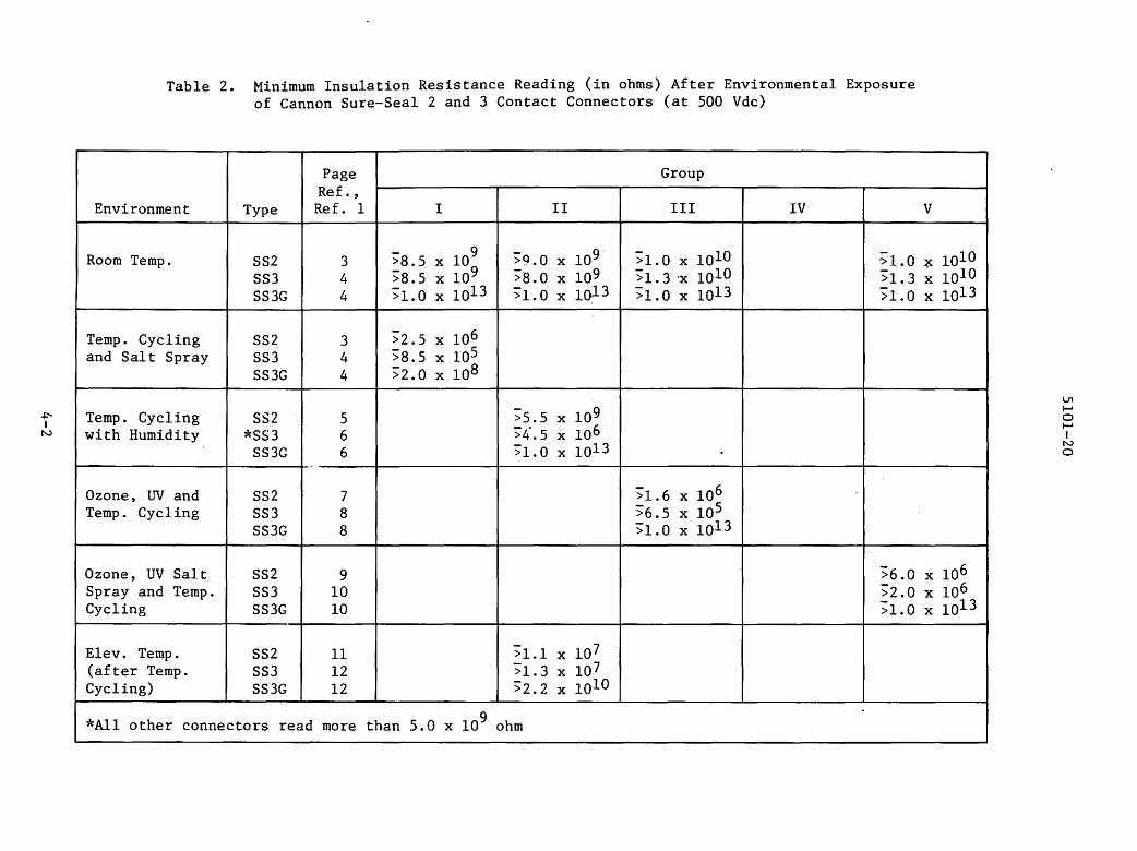
The two·electrical parameters monitored throughout the environmental portion of the test program are Insulation Resistance and Contact Resistance. This selection was made because these two measurements better explore the weaknesses of this type of component when exposed to a severe environment. Recognizing that these connectors and contacts were designed for a low voltage operation, the results were encouraging. See Table 2 for minimum insulation resistance readings in each of the groups after the various environmental exposures. Table 3 shows the contact resistance results after exposure.
1. Room Temperature - All Groups
Table 2 shows the room temperature readings prior to Groups I, II, III and V being exposed to any environment.
All readings were above the minimum acceptable of 100 megohms (1 x 10⁸ n ). The lowest insulation resistance reading was 8.0 x 10⁹n for the black Nitrile rubber connector and 1.0 x 10¹³ !2 for every EPDM (gray) connector.
2. Temperature Cycling and Salt Spray - Group I
a. Ten 2-conductor (SS2) connectors
Insulation Resistance - Five were above the acceptable 1 x 10⁸ n
Contact Resistance - Resistance increases ranged from . 00013 0 to • 00433 S'2 •
Visual Inspection - The post environment condition of this group is good except for crazing on each connector.
(1) Connector #9 (plug side) - Socket contact was broken off at crimp-socket neck down.
(2) Connector #10 - Severe split at hole position #1 plug. Physical damage to connectors #9 and #10 in this group occurred during contact retention test.
4-1
.i:-,
I N
Table 2.
Environment
Room Temp.
Temp. Cycling and Salt Spray
Temp. Cycling with Humidity
Ozone, UV and Temp. Cycling
Ozone, UV Salt Spray and Temp. Cycling
Elev. Temp. (after Temp. Cycling)
Minimum Insulation Resistance Reading (in ohms) After Environmental Exposure of Cannon Sure-Seal 2 and 3 Contact Connectors (at 500 Vdc)
Page Group Ref.,
Type Ref. 1 I II III IV V
SS2 3 >8.5 X 10⁹ >9.Q X 109· >1.0 X 1010 ">LO ~ SS3 4 >8.5 X 10⁹ >8.Q X 109 >l. 3 'X 1010 >1.3 X
SS3G 4 >l.Q X 1013 >l.Q X 1013 >l.Q X 1013 >l.Q X
SS2 3 >2.5 X 10⁶ SS3 4 >8.5 X 10⁵ SS3G 4 >2.Q X 108
SS2 5 ;5. 5 X 10⁹ *SS3 6 >4 .. 5 X 10⁶
SS3G 6 >1.Q X 1013
SS2 7 >1.6 X 10⁶ SS3 8 >6.5 X 10⁵ SS3G 8 >l.Q X 1013
SS2 9 >6.0 X
SS3 10 >2.0 X
SS3G 10 >l.Q X
SS2 11 >1.1 X 10⁷ SS3 12 >1.3 X 10⁷ SS3G 12 >2.2 X 10¹⁰
*All other connectors read more than 5.0 x 10⁹ ohm
1010 1010 1013
106 106 1013
u, ..... 0 ..... I
N 0

5101-20
Table 3. Maximum Contact Resistance Increase (in ohms) After Environmental Exposure
Group Page
Environment Type Ref. 1 I II Ill IV
Temperature SS2-R 13 9.06 X 10⁻⁴
Cycling SS2-B 13 7. 30 X 10-4 (with Humidity)
10-4 and Salt Spray SS2G-R 13 1. 30 X
SS2G-B 13 3.04 X 10⁻⁴
SS3-R 14-15 1, 79 X 10- 3
SS3-B 14-15 8.94 X 10⁻⁴
SS3-W 14-15 8.09 X 10⁻⁴
SS3G-R 14 1.68 X 10⁻³
SS3G-B 14 1. 79 X 10- 3
SS3G-W 14 1. 56 X 10- 3
Temperature SS2-R 16 2.82 X 10⁻⁴
Cycling SS2-B 16 l. 35 X 10-4 with Humidity
SS3-R 17 1.86 X 10-l
SS3-B 17 1. 29 X 10-4
SS3-W 17 1.18 X 10⁻⁴
SS3G-R 18 1.02 X 10⁻⁴
SS3G-B 18 6.90 X 10⁻⁵
SS3G-W 18 ). 53 X 10-4
Ozone, UV and SS2-R 19 2.21 X 10⁻³
Temperature SS2-B Cycling 19 8.86 X 10⁻⁴
SS3-R 21 1.16 X 10⁻³
SS3-B 21 9.32 X 10⁻⁴
SS3-W 21 7.01 X 10⁻⁴
SS3G-R 20 6 .16 X 10-4
SS3G-B 20 1.48 X 10⁻³
SS3G-W 20 5.80 X 10⁻⁴
Ozone, UV SS3-R 22 Salt Spray and SS3-B 22 Temperature Cycling (with SS3-W 22 Humidity)
SS3G-R 23
SS3G-B 23
SS3G-W 23
Note: There was one unexplained reading of -6.00 X 10 -5 increase in resistance in this group.
4-3
V
(See Note)
2.11 X 10⁻³
2.47 X 10⁻³
3.82 X 10⁻³
1. 54 X 10-J
6.62 X 10⁻⁴
2.06 X 10-J

5101-20
b. Ten 3-conductor (SS3) connectors
Insulation Resistance - The single EPDM (gray) connector was the only one to surpass the minimum requirements. Six of the black connector readings were greater than 1 x 10⁶ 0 , three were greater than 10 x 106 Q • The EPDM (gray) connector provided readings greater than 200 x 106 0 .
Contact Resistance - Resistance.increases ranged from 8 x 10⁻⁵ 0 to .79 x 10 3g . The EPDM (gray) connector had larger resistance increases than the black connectors in this group.
Visual Inspection - The post environment condition of this group is good except for crazing on each Nitrile rubber (black) connector. The EPDM (gray) connector had no visible defects.
3. Temperature Cycling with Humidity - Group II
a. Ten 2-conductor (SS2) connectors
9 Insulation Resistance - All measured greater than 5.5 x 10 n.
Contact Resistance - Resistance increases ranged from .97 x 10-5 n to 1.3 x 10⁻⁴ 0. There was one negative increase (-.000015 n) that was an apparent instrumentation error.
Visual Inspection - The post environment condition of this group is good except for crazing on every connector.
b. Ten 2-conductor (SS3) connectors
Insulation Resistance - Nine measured greater than 5.5 x 10⁹ n. One measured 4.5 x 10⁶ O and could have been the result of a poor seal.
Contact Resistance - Connector #7 (black) contact #2 (red wire) read high initially (.019 0) and had the highest increase ( .18 0 ) which may have been a poor seal and low surface contact area (the crimp looked good). The other resistance increases ranged from 1. 4 x 10-S O to 1. 8 x 10-l O •
Visual Inspection - The post environment of this group is good except for crazing on each connector and except for the EPDM (gray) connector which had slight hole deformities where the wire exits the holes.
4-4

5101-20
4. Ozone, UV and Temperature Cycling with Humidity - Group III
a. Ten 2-conductor (SS2) connectors
Insulation Resistance - Eight measured greater than 1.5 x 10⁸
g. The low readings were 1.6 x 10⁶ n and 2.8 x 10⁷ n.
Contact Resistance - Resistance increases were closely grouped and ranged from 8 x 10⁻⁴ n to 2.2 x 10⁻³ 0. In seven of the ten connectors in this group the higher resistance increases occurred on the red wire contact and the initial resistance reading was in most cases lower than the brown wire. (See 5 b below)
Visual Inspection - The post environment condition of this group is poor. All connectors exhibit crazing and cracks are visible (some severe) where the wires enter the plug and receptacle. Additionally, cracks are also visible between hole positions at plug and receptacle wire entry points.
b. Ten 3-conductor (SS3) connectors
Insulation Resistance - Seven measured greater than 5.0 x 10⁸ n .
Contact Resistance - Resistance increases were again very closely grouped and ranged from 9 x 10⁻⁵ n to .10 x 10-3 n . Twenty seven (27) readings ranged from 1. 2 X 10⁻⁴ 0 to 9. 3 x 10⁻⁴ 0 . There are 30 readings in every 3-conductor connector group.
Visual Inspection - Same as 4 a above, except for the EPDM (gray) connector. It appears unaffected by the environment, but did exhibit slight hole deformation at wire entry into plug and receptacle as a result of being wrapped on the 4" mandrel during the ozone exposure.
5. Ozone, UV, Salt Spray and Temperature Cycling - Group V
a. Ten 2-conductor (SS2) connectors
Insulation Resistance - Five of these connectors measured greater than 1.6 x 10⁸ n. Of the other five, one measured 6 x 10⁶ 0 and the other fou~ measured between 1. 4 x 10⁷ n and 7. 5 x 10⁷ n .
Contact Resistance - Resistance increases ranged from 7 x 10⁻⁵ n to 3.7 x 10⁻³ n. In seven of ten connectors the higher resistance change occurred in the red wire contact (position #2).
Visual Inspection - Same as Group III (4 a above) except:
(1) On connector #1, plug position #1 (brown wire) socket broke off at crimp-socket neck-down area.
4-5

5101-20
(2) The EPDM (gray) connector had no visible marks except for slightly deformed holes at wire entry on plug and receptacle. This resulted from being wrapped on the 4" mandrel during ozone exposure.
In approximately half of the above tests the data indicates a larger contact resistance increase in the red wire contact. The smaller outside diameter of the red wire (red= .1040, brown= .1050, white= .1055) apparently allowed more moisture to enter the cavity and affect the contact resistance to a greater degree.
6. Insulation Resistance at High Temperature - Group II
a. Ten 2-conductor (SS2) connectors
7 All readings were very consistent ranging from 1.1 x 10 0 to 1. 4 X lQ 7 0 .
b. Ten 3-conductor (SS3) connectors
All readings were ver7 consistent for the black connectors ranging from 1. 3 x 10 0 to 4. 5 x 10 7 0 . The EPDM (gray) connector had very high readings of 2.0 x 10¹⁰ 0 to 4.5 x 10¹⁰ n.
7. Temperature Cycling and Salt Spray - Group VI - 50 Mated Bare Contacts
The last test performed at Delsen Labs was to expose 50 mated bare contacts to Temperature Cycling (with humidity) and subsequently to a Salt Spray environment. A resistance reading was taken prior to, and after exposure. The following are the resistance readings under the conditions specified.
(1) Room Temperature (prior to exposure) - from 1.36 x 10⁻³ n to 1.66 X 10⁻³g .
(2) After exposure - from 1. 44 x 10-3 Sl to 3. 28 x 10-3 n .
(3) The resistance increase subsequent to exposure - from 6. 60 X 10-5 Q to 1. 69 X 10-3 (2 .
After being exposed to Temperature Cycling and Salt Spray, 43 resistance increases were from 1 x 10-40 to 8 x 10⁻⁴ 0 ; four were from 6 x 10⁻⁵ n to 9 X 10- 5 {l; and three were 12 X 10-4 {l to 16 X lQ-4 {l .
All 50 mated pairs of contacts passed the m1n1mum specified resistance (1 x 10⁻² 0) specified subsequent to exposure. A visual inspection subsequent to exposure reveals deposits of salt externally with very small quantities in the pin to socket sidewall contact area.
4-6

5101-20
B. JPL TESTS, INSPECTIONS, AND ANALYSIS
Results of the JPL tests performed on samples after environmental exposure at Delsen Labs (see above) are given in Table 4.
Table 4. Results of Tests Performed at JPL on Groups I, II, III, and V After Environmental Exposure at Delsen Labs (see Table 1)
Test Acceptance Group Results Criteria
No I II See Visual Inspection, Visual irregularities III V summary pages
Contact/Conn. Hold 10 lb II V Passed Retention 1 minute
Contact/Conn. Remove/insert
Durability contacts II V Performed 5 times
Contact/Conn. Hold 8 lb, II V Passed Retention 1 minute
10 lb Black connectors - 25 to 30 Pull Test minimum II V Grey (EPDM) conns. -15 to
20 lb (See Note)
Voltage 1500 vac, I II Passed Withstanding 1 minute III V
Visual No II V See Visual Inspection irregularities
Note: Group V: plug #1 - pin #1 broke during pull test.
4-7
lb

5101-20
A total of 14 connectors in Group IV were tested at JPL; these were subdivided into two groups of five each for the 2-conductor and 3-conductor Nitrile rubber connectors. In the third subgroup, there were four 3-conductor EPDM (gray) connectors. All thee subgroups were subjected to identical tests as shown in Tables 5, 6, and 7.
1. Visua 1 Ins pl:'L' t ion
All tl1ree subgroups looked good and contained no irregularities.
2. Insula t iL,n Resistance
Prior to start of tests. All three subgroups passed this test with rt>adings w12ll above the 1 x 10⁸ 0 minimum.
3. Contact/Connector Retention
a. Hold 10 lb for 1 minute (each contact)
(1) Five 2 conductor Nitrile rubber (black) connectors -Two of the five connectors, Specimens X and Y, had one contact on the plug half (position #2) pull out at 45 seconds.
(2) Five 3-conductor Nitrile rubber (black) connectors -All five specimens passed this test.
(3) Four conductor EPDM (gray) connectors - All four connectors in this group experienced problems in this test. (See Table 8).
b. Pull Test - rate of 10" ± 2" per minute - 10 lb minimum. All 14 connectors in the subgroups passed this test.
4. Contact/Connector Durability
All 14 connectors in the three subgroups were submitted to the removal and insertion of the contacts five times (with the proper tool).
5. Insulation Resistance
After 3 and 4 above. All 14 connectors in the three subgroups passed this test with readings well above the minimum 1 x 10⁸ 0 .
4-8

5101-20
Table 5. Group IV Connector Contact Test - 2-Conductor Black
Test
Visual (6x)
Insulation Resistance @5oo voe (Note 1)
Contact/Conn Retention
Contact/Conn Durability
Insulation Resistance @soo voe (Note 1)
Contact/Conn Retention
Dielectric Test 1500 VAC
Visual (6x)
Acceptance Criteria
(Note 2)
Min. n 1 X 10⁸
Hold, 10 lb, 1 min
Pull, 10-lb min.
Remove/ insert cycle, 5 times
Min. n 1 X 10⁸
Hold, 8 lb, 1 min
Pull, 8-lb min.
1 minute
(Note 2)
V
>1 X 10¹⁰n
./
Specimen ID
w X y
None noted
>4. 5 X 10⁹!:2
./ 2P = 45s 2P = 45s
All 5 specimens passed 10-lb min. pull test (Avg. 21-lb pull)
~~------+------------- Performed
I ./ ./ 2P = 42s
All 5 specimens passed 8-lb min. pull test
All 5 specimens passed 1500 VAC ll.'St
Note 1: Insulation Resistance readings are taken between each pair of l'nndtu:tors.
Note 2: No Irregularities.
4-9
z
I
>,85 X 109Q

5101-20
Table 6. Group IV Connector Contact Test - 3-Conductor Black (Nitrile Rubber)
Specimen ID
Test Acceptance
V w X y Criteria
Visual (6x) (Note 2) - None noted -
Insulation >l. 2 X 10⁹ '.• l. 1 X 10⁹ > 1.1 X 10⁹ >I. 4 x 10⁹
Resistance Min. n > 1. 2 X 10⁹ >1.2 X 10⁹ > 1. 2 X 10⁹ ··1.4 X 10⁹
@500 VDC l X 108 >1. 2 X 10⁹ >1.2 X 10⁹ '• 1.1 X 10⁹ > 1.4 X 10⁹
(Note 1) .
Hold 10 lb, All 5 specimens passed 10 lb hold test
Contact/Conn 1 min I I Retention I I Pull
All 5 specimens passed the 10-lb min. Pull Test (Avg. 10 lb min
..
Remove/ Contact/Conn insert - Performed Durability cycle,
5 times
Insulation Min Sl > 1.] X 109
·· J. l X 109 ··0.95 X 10⁹ '•0.95 X 10⁹ Res istan<'l'
I 108 >l.4 X 109 > 1.1 X 10⁹ ·· 1.1 X 10⁹ >I. 1 X 10⁹ X @500 VDC >l.) X 109 ··I. 2 x 10⁹ '• l. l X 109 > 1.1 X 10⁹
(Note 1)
Hold, 8 lb, All 5 specimens passed the 8-lb hold test
Contact/Conn l min I I Retention
I I Pull 8 lb Al I 5 specimens passed the 8 lb min. pul 1 test (Avg. l min
Dielectric Test I min All 5 specimens passed the 1500 VAC test 1500 VAC
Visual (Note 2) - None noted
Note l: Insulation resist;mce rc:1dings are taken hl·twc•cn c,1ch pair of conductors.
Nole 2: No irrcgulariti<•s.
4-10
20
15
z
-
> 1.1 X 10⁹ ··l.] X 109 >l,] X 109
lb.)
-
-..l.Q X 109 >I .I X 109 , l. l X 109
lb)
-

5101-20
Table 7. Group IV Connector Contact Test - 3-Conductor Gray (EPDM)
Specimen ID
Acceptance Test Criteria w X y
Visual (6x) (Note 2) - None noted -
Insulation Resistance Min. 0 00 00 00 @500 voe l X 108 (Note l)
lR = J8s Hold, JR 17s IP = 2Js
= JP = 50s 2P = lJs 10 lb, l min 2P = JOs 58s JP =
Contact/Conn JP = 42s Retention
Pull, 10-lb min. All 4 specimens passed 10-lb min. pull test
Remove/ Contact/Conn insert Performed Durability cycle,
5 times
Insulation Resistance Min.
108 (1500 \'DC 1 X 00 00 00
(Note l)
Hold, lR = 55s 2P 54s lP = 49s =
8 lb, 1 min 2P = 14s 2P = 48s Contact/Conn Retention
Pull, 8-lb min. All 4 specimens passed 8-lb pull test (Avg. 10-15
Dielectric Test l minute All 4 specimens passed test 1500 VAC
Visual (6x) {Note 2)
Note 1: Insulation Resistance readings are taken between each pair of conductors.
Note 2: No irregularities
4-11
z
--
·00
JP =
00
3P =
lb.)
13s
51s

5101-20
Table 8. High Voltage Breakdown Test, Two Specimens From Groups I, II, III, and V Including all EPDM (SS3G) Connectors
Test Conn. Test Points Type Voltage Breakdown Ranges
SS2 4 KV to 5 KV
Lead-to-Lead SS3 4 KV to 5 KV
SS3G 5 KV to 7 KV
High Voltage
Breakdown
SS2 5 KV to 6 KV
All Leads to "Case" SS3 5 KV to 6 KV (See Note)
SS3G 5 KV to 7 KV
Note: Since the "case" of these connectors is non-metallic, a metal shield was placed around the connector and the voltage was impressed between the "case" and all leads shorted together.
4-12

5101-20
6. Contact/Connector Retention
Subsequent to above tests.
a. Hold 8 lb for one minute - Only one connector, Specimen Y, did not meet the 60-second requirement. The same contact, position #2 on the plug side held for only 42 seconds.
b. Pull Test - rate of 10": 2" per minute - 8 lb minimum. All 14 connectors in the 3 subgroups passed the test.
7. Dielectric Test
1500 Vac for one minute. All 14 connectors in the three subgroups passed this test.
8. Visual Inspection
a. Five 2-conductor Nitrile rubber black connectors - Specimens X, Y, and Z have mold flash on the pin contact hole perimeter.
b. Five )-contact Nitrile rubber black connectors - No damage or other irregularities are evident in this group.
c. Four )-contact EPDM gray connectors - The only irregularity visible is the slight deformation of the wire entry holes.
Tests 3, 4, and 6 indicate that the Nitrile rubber and PVC (black) connectors have better retention characteristics than the EPDM (gray) connectors. The EPDM connectors are not as resilient as the black connectors and therefore the routing of the wires exiting the plug and receptacle holes can easily cause the deformation evident in the four specimens in this group. The connectors with their leads (12" leads on each half of the connectors) in a circle were stored for 4 weeks in a plastic envelop and this caused the hole deformation.
9. Dielectric Withstanding Voltage
This was the last test performed on this connector at JPL. Two Nitrile rubber specimens from Groups I, II, III, IV, and Vandall the EPDM (gray) connectors (9 total) were subjected to this test.
The Nitrile rubber (black) connectors averaged 5-6 kV before experiencing breakdown and the EPDM (gray) connectors averaged 6-7 kV.
4-13

5101-20
SECTION V
CONCLUSIONS
The results of the tests conducted on the ITT Cannon Sure-Seal connector at Delsen Labs Inc. and at JPL indicate that the low-cost connector has a great potential in the solar panel interconnect application for voltages up to and including 250 Vdc.*
The connector performance was better than expected, particularly gi.ven the difference of the tested application from the application for which this connector was designed. There were differences in the performance of connectors made of Nitrile rubber and PVC (current production version) and EPDM (Ethylene Propylene Diene Monomer).
The EPDM connector did not perform as well as the production version in the moisture environment, and did not exhibit as great a holding force (these are responsive to design change and careful engineering). The EPDM connector appears to be impervious to effects of ozone and UV environments, which were extremely harsh on the production version.
Subsequent to the test, the design has been modified to provide a longer wire-entry barrel, with a total of six ~ealing serrations, improving the moisture barrier and answering one of the EPDM connector concerns. Proper routing and strain relief will minimize if, not dispose of, the holding force problem.
* The ITT Cannon Sure-Seal connector has been approved by the Underwriters Laboratory for 230 vac service.
5-1

5101-20
REFERENCES
1. Delsen Corporation Testing Laboratories, Report No. T. 12684, 28 May 1976 (LSSA Project Data Center Retrieval Code 3A020).
2. MIL-STD-202C - Test Methods for Electronic and Electrical Component Parts.
3. ASTM G23-69 - Standard Recommended Practice for Operating Light and Water Exposure Apparatus (Carbon-Arc Type) for Exposure of Nonmetallic Materials.
4. ASTM D1149-64 - Standard Method of Test for Accelerated Ozone Cracking of Vulcanized Rubber.
6-1
NASA-Jl'L-Coml., LA. Cahl