Embed Size (px)
Citation preview

NOTICEAlways follow the directions given in the above repair manuals when handlingsupplemental restraint system components (such as removal, installation,inspection, etc.) in order to prevent accidents and supplemental restraintsystem malfunction.
2006All rights reserved. This book may not bereproduced or copied, in whole or in part, withoutthe written permission of Toyota MotorCorporation.First Printing : Jan. 13, 2006 01–060113–00
FOREWORD
This wiring diagram manual has been prepared to provide
information on the electrical system of the 2007 CAMRY.
Applicable models: GSV40 Series
ACV40 Series
Refer to the following manuals for additional service
specifications and repair procedures for these models:
Manual Name Pub. No. 2007 CAMRY Repair Manual
2007 CAMRY New Car Features
RM0250U
NM0250U
All information in this manual is based on the latest product
information at the time of publication. However, specifications
and procedures are subject to change without notice.

CAMRY (EM0250U)
1
2007 CAMRYELECTRICAL WIRING DIAGRAM
Section Code Page
INTRODUCTION A. . . . . . . . . . . . . . . . . . . . . . . . . . . . . . . 2
HOW TO USE THIS MANUAL B. . . . . . . . . . . . . . . . . . . 3
TROUBLESHOOTING C. . . . . . . . . . . . . . . . . . . . . . . . . . 12
ABBREVIATIONS D. . . . . . . . . . . . . . . . . . . . . . . . . . . . . 17
GLOSSARY OF TERMS AND SYMBOLS E. . . . . . . . . 18
RELAY LOCATIONS F. . . . . . . . . . . . . . . . . . . . . . . . . . . 20
ELECTRICAL WIRING ROUTING G. . . . . . . . . . . . . . . 48
SYSTEM CIRCUITS H. . . . . . . . . . . . . . . . . . . . . . . . . . . . 70
GROUND POINT I. . . . . . . . . . . . . . . . . . . . . . . . . . . . . . . 396
POWER SOURCE (Current Flow Chart) J. . . . . . . . . 404
CONNECTOR LIST K. . . . . . . . . . . . . . . . . . . . . . . . . . . . 414
PART NUMBER OF CONNECTORS L. . . . . . . . . . . . . 436
OVERALL ELECTRICAL WIRING DIAGRAM M. . . . . 440

2
CAMRY (EM0250U)
A INTRODUCTION
This manual consists of the following 13 sections:
No. Section Description
AINDEX Index of the contents of this manual.
AINTRODUCTION Brief explanation of each section.
B HOW TO USE THISMANUAL Instructions on how to use this manual.
C TROUBLE–SHOOTING Describes the basic inspection procedures for electrical circuits.
D ABBREVIATIONS Defines the abbreviations used in this manual.
EGLOSSARY OFTERMS ANDSYMBOLS
Defines the symbols and functions of major parts.
F RELAY LOCATIONS Shows position of the Electronic Control Unit, Relays, Relay Block, etc.This section is closely related to the system circuit.
G ELECTRICALWIRING ROUTING
Describes position of Parts Connectors, Splice points, Ground points, etc.This section is closely related to the system circuit.
H
INDEX Index of the system circuits.
HSYSTEM CIRCUITS
Electrical circuits of each system are shown from the power supply through groundpoints. Wiring connections and their positions are shown and classified by codeaccording to the connection method. (Refer to the section, ”How to use this manual”).The ”System Outline” and ”Service Hints” useful for troubleshooting are also containedin this section.
I GROUND POINT Shows ground positions of all parts described in this manual.
J POWER SOURCE(Current Flow Chart) Describes power distribution from the power supply to various electrical loads.
K CONNECTOR LIST Describes the form of the connectors for the parts appeared in this book.This section is closely related to the system circuit.
L PART NUMBER OFCONNECTORS Indicates the part number of the connectors used in this manual.
MOVERALLELECTRICALWIRING DIAGRAM
Provides circuit diagrams showing the circuit connections.

CAMRY (EM0250U)
3
HOW TO USE THIS MANUAL B
This manual provides information on the electrical circuits installed on vehicles bydividing them into a circuit for each system.
The actual wiring of each system circuit is shown from the point where the powersource is received from the battery as far as each ground point. (All circuitdiagrams are shown with the switches in the OFF position.)
When troubleshooting any problem, first understand the operation of the circuitwhere the problem was detected (see System Circuit section), the power sourcesupplying power to that circuit (see Power Source section), and the ground points(see Ground Point section). See the System Outline to understand the circuitoperation.
When the circuit operation is understood, begin troubleshooting of the problemcircuit to isolate the cause. Use Relay Location and Electrical Wiring Routingsections to find each part, junction block and wiring harness connectors, wiringharness and wiring harness connectors and ground points of each system circuit.Internal wiring for each junction block is also provided for better understanding ofconnection within a junction block.Wiring related to each system is indicated in each system circuit by arrows(from__, to__). When overall connections are required, see the Overall ElectricalWiring Diagram at the end of this manual.
[B]W
– R
G –
W
Ski
d C
ontr
ol E
CU
with
Act
uato
r
G –
W
H7
Y –
G
Com
bina
tion
Met
er
R –
L
Rea
rLi
ghts
R –
L
(S/D
)(S
/D)
(S/D
)
(W/G
)
G –
B
W –
B
W –
B
Rea
r C
ombi
natio
n La
mp
(LH
)H
9
W –
BW
– B
Rea
r C
ombi
natio
n La
mp
(RH
)J7
W –
BG
– R
Sto
p
Sto
p
G –
RG
– R
7
LL
R
L
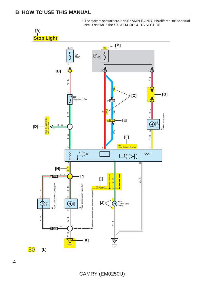
Stop Light
2
(BAT)
15ASTOP
(IG)
IBIB
7.5AGAUGE
3 41
[A]
H6Stop Lamp SW
G – W
1
2
[D]
[C]
[E]
[F]
[G]
[M]
H4Light Failure Sensor
3C
3C
15 CH1
CH114
7
15
48
13
4
50
[J]
[H]
[N]
[K]
[L]
[I]
11
H17Center StopLamp
(Shielded)
H1 H2
HJ1W – B
G – RHJ1
1
2
6
3
3
4
1
1
12
4
CAMRY (EM0250U)
B HOW TO USE THIS MANUAL
* The system shown here is an EXAMPLE ONLY. It is different to the actualcircuit shown in the SYSTEM CIRCUITS SECTION.

CAMRY (EM0250U)
5
B
[A] : System Title
[B] : Indicates a Relay Block. No shading is used andonly the Relay Block No. is shown to distinguish itfrom the J/BExample: Indicates Relay Block No.1
[C] : ( ) is used to indicate different wiring andconnector, etc. when the vehicle model, enginetype, or specification is different.
[D] : Indicates related system.
[E] : Indicates the code for the (male and female)connectors which are used to join two wireharnesses. The connector code consists of twoalphabetical and one numerical characters.
Female Male ( )
The first character of the connector code indicatesthe alphabetical code allocated to the wire harnesswhich has the female connector, and the secondshows that of the wire harness which has the maleconnector.The third character indicates a serial number usedto distinguish between the wire harnesscombinations in cases when more than one of thesame combination of wire harnesses exist (e.g. CH1 and CH2).
Symbol ( ) indicates the male terminal connector.Numbers outside connector codes indicate the pinnumbers of both male and female connectors.
[F] : Represents a part (all parts are shown in sky blue).The code is the same as the code used in partsposition.
[G] : Junction Block (The number in the circle is the J/BNo. and the connector code is shown beside it).Junction Blocks are shaded to clearly separatethem from other parts.
3C indicates thatit is insideJunction BlockNo.3
Example:
[H] : Indicates the wiring color.
Wire colors are indicated by an alphabetical code.
B = Black W = White BR = Brown
L = Blue V = Violet SB = Sky Blue
R = Red G = Green LG = Light Green
P = Pink Y = Yellow GR = Gray
O = Orange
The first letter indicates the basic wire color and thesecond letter indicates the color of the stripe.
Example: L – Y
L(Blue)
Y(Yellow)
[I] : Indicates a shielded cable.
[J] : Indicates the pin number of the connector.The numbering system is different for female andmale connectors.
Example: Numbered in otherfrom upper left tolower right
Numbered in otherfrom upper right tolower left
Female Male
[K] : Indicates the ground point. The code consists of thetwo characters: A letter and number.The first character of the code indicates thealphabetical code allocated to the wire harness.The second character indicates a serial numberused to distinguish between the ground points incases when more than one ground point exist on thesame wire harness.
[L] : Page No.
[M] : Indicates the ignition key position(s) when thepower is supplied to the fuse(s).
[N] : Indicates a wiring Splice Point.
Example:
[O]
[P]
[Q]
[R]
[S]
[T]
6
CAMRY (EM0250U)
B HOW TO USE THIS MANUAL
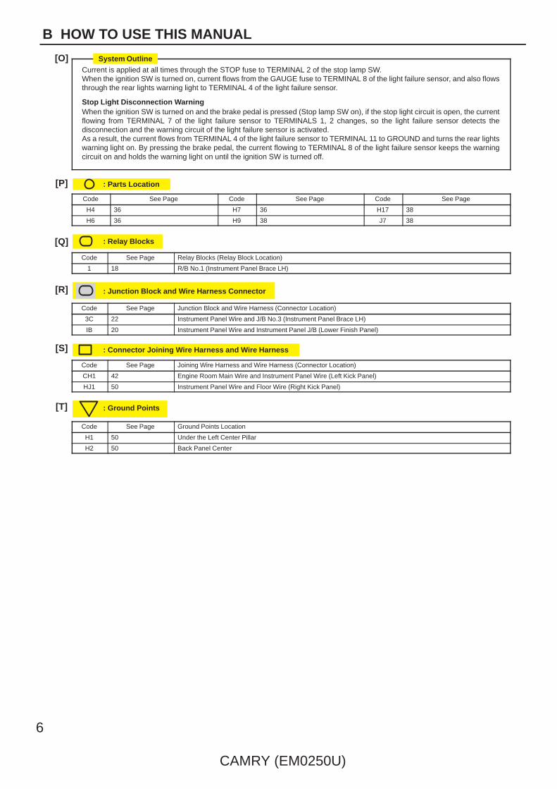
Current is applied at all times through the STOP fuse to TERMINAL 2 of the stop lamp SW.When the ignition SW is turned on, current flows from the GAUGE fuse to TERMINAL 8 of the light failure sensor, and also flowsthrough the rear lights warning light to TERMINAL 4 of the light failure sensor.
Stop Light Disconnection WarningWhen the ignition SW is turned on and the brake pedal is pressed (Stop lamp SW on), if the stop light circuit is open, the currentflowing from TERMINAL 7 of the light failure sensor to TERMINALS 1, 2 changes, so the light failure sensor detects thedisconnection and the warning circuit of the light failure sensor is activated.As a result, the current flows from TERMINAL 4 of the light failure sensor to TERMINAL 11 to GROUND and turns the rear lightswarning light on. By pressing the brake pedal, the current flowing to TERMINAL 8 of the light failure sensor keeps the warningcircuit on and holds the warning light on until the ignition SW is turned off.
: Parts Location
Code See Page Code See Page Code See Page
H4 36 H7 36 H17 38
H6 36 H9 38 J7 38
: Relay Blocks
Code See Page Relay Blocks (Relay Block Location)
1 18 R/B No.1 (Instrument Panel Brace LH)
: Junction Block and Wire Harness Connector
Code See Page Junction Block and Wire Harness (Connector Location)
3C 22 Instrument Panel Wire and J/B No.3 (Instrument Panel Brace LH)
IB 20 Instrument Panel Wire and Instrument Panel J/B (Lower Finish Panel)
: Connector Joining Wire Harness and Wire Harness
Code See Page Joining Wire Harness and Wire Harness (Connector Location)
CH1 42 Engine Room Main Wire and Instrument Panel Wire (Left Kick Panel)
HJ1 50 Instrument Panel Wire and Floor Wire (Right Kick Panel)
: Ground Points
Code See Page Ground Points Location
H1 50 Under the Left Center Pillar
H2 50 Back Panel Center
System Outline

CAMRY (EM0250U)
7
B
[O] : Explains the system outline.
[P] : Indicates reference pages showing the parts locations in the system circuit on the vehicle.
Example : Code ”H4” (Light Failure Sensor) is on page 36 of the manual.* The first character of the code indicates the alphabetical code allocated to the wire harness, and the
second character indicates the serial number of the parts connected to the wire harness.
ÁÁ
Serial number for the connected partsCode for the wire harness
Example : H 4
[Q] : Indicates the reference page showing the position on the vehicle of Relay Block Connectors in the system circuit.
Example : Connector ”1” is described on page 18 of this manual and is installed on the left side of the instrumentpanel.
[R] : Indicates the reference page showing the position on the vehicle of J/B and Wire Harness in the system circuit.
Example : Connector ”3C” connects the Instrument Panel Wire and J/B No.3. It is described on page 22 of thismanual, and is installed on the instrument panel left side.
[S] : Indicates the reference page describing the wiring harness and wiring harness connector (the female wiringharness is shown first, followed by the male wiring harness).
Example : Connector ”CH1” connects the Engine Room Main Wire (female) and Instrument Panel Wire (male).It is described on page 42 of this manual, and is installed on the left side kick panel.
[T] : Indicates the reference page showing the position of the ground points on the vehicle.
Example : Ground point ”H2” is described on page 50 of this manual and is installed on the back panel center.

8
CAMRY (EM0250U)
B HOW TO USE THIS MANUAL
The ground points circuit diagram shows the connections from all major parts to the respective ground points. Whentroubleshooting a faulty ground point, checking the system circuits which use a common ground may help you identifythe problem ground quickly. The relationship between ground points ( A1 , A2 and D4 shown below) can also bechecked this way.
I GROUND POINT
B36W
– B
W –
B
W –
B
Junc
tion
Con
nect
or(S
hiel
ded)
(Shi
elde
d)
BR
W –
BW
– B
A25
W –
BW
– B
W –
B
W –
B
Junc
tion
Con
nect
or
17
18
19
20
3
8
7
4
1
6
5
34
2
DLC3
A20
L5
A22
A8
A5
A23
A11
I9
A21
K5
A1
A10
C4
C2
(E)
(E)
(E)
(L)
(E1)
(E1)
(E01)
(E02)
(LH E)
(E)
(E)
(RH E)
(–S)
(E)
(E)
(E)
(E)
(E)
(SG)
D2
D63
D60
A6
ThrottlePosition SW
D4 (5L–E)
JunctionConnector
(Shielded)BRBRBR
LA13
DB1
12 7
CA15
HA1
KA13
IH2
HB4912
D43
11
10
BR
BR
BR
BR
BR
W – B
W – B W – B
W – B
W – B
W – B
W – B
W – B
W – BW – BW – B
W – B
W – B
W – B
W – B
W – B
W – B
W – B
W – B
W – B
W – B
W – B
A1
Power WindowMaster SW
Turn Signal Lamp(Front RH)
Brake Fluid LevelWarning SW
Fog Lamp(Front RH)
Fog Lamp(Front LH)
Engine ECU
InjectionPump Assembly
Clearance Lamp(Front LH)
Clearance Lamp(Front RH)
HeadlampLeveling SW
WindshieldWiper Motor
Turn Signal Lamp(Front LH)
Pressure SW
Headlamp LevelingMotor (RH)
Cooling FanMotor No.3
Power WindowMaster SW
Headlamp LevelingMotor (LH)
H23
(E)
(E)
A24(GND2)
(GND1)
(GND)
(GND)
B19
(Shielded)
(Shielded)
(Shielded)
(Shielded)
W – B
W – B
W – B
W – BW – B
W – B
W – B
W – B
21AB1
12AB1
W – B
W – B
W – B
W – B
Skid Control ECUwith Actuator
Option Connector(Vacuum)
6AB1
A2
16
* The system shown here is an EXAMPLE ONLY. It is different to the actual circuit shown in the SYSTEM CIRCUITS SECTION.

CAMRY (EM0250U)
9
B
The ”Current Flow Chart” section, describes which parts each power source (fuses, fusible links, and circuit breakers)transmits current to. In the Power Source circuit diagram, the conditions when battery power is supplied to each systemare explained. Since all System Circuit diagrams start from the power source, the power source system must be fullyunderstood.
AM
2
AM
1
IG2
AC
C
IG1
ST
1
ST
2
W –
R
W
J POWER SOURCE (Current Flow Chart)The chart below shows the route by which current flows from the battery to each electrical source(Fusible Link, Circuit Breaker, Fues, etc.) and other parts
30A AM2
Starter
Battery Fusible Link Block
100A ALT
2 6
6
Short Pin10A ECU–B
7.5A DOME2
15A EFI
10A HAZARD
20A RADIO NO.1
10A HORN
60A ABS
2
2
S 2
5
Engine Room R/B (See Page 20)
194187180166210
214230112122
Page
ABSABS and Traction ControlCruise ControlElectronically Controlled TransmissionMultiplex Communication System
Fuse
STOP20A
10A DOME
Cigarette LighterCombination MeterHeadlightInterior LightKey Reminder and Seat Belt WarningLight Auto Turn Off System
System
Theft Deterrent and Door Lock Control
1.25BFL MAIN
Power Source
50A MAIN
4
11 2
1W – R
20A DEFOG
B – Y
8
2
H8
W – R
Ignition SW
11
7.5A DOME
21
RWAH1
7
AH1
BA11
6
W
WW
Battery
B
B
B2
21
22
2
2
7.5A AM1
15A HAZ–RADIO
1
212
W
∗ The system shown here is an EXAMPLE ONLY. It is different to the actual circuit shown in the SYSTEM CIRCUITS SECTION.
BlackB1
K CONNECTOR LIST
1 2 3 4
BlackA1
1 2 3 4
5 6 7 8
A2
1 2 3 4 5 76
GrayA3
1 2
3 4 5 61 2 3 4 56 7 8 9 10111213
B2
[A] [C]
[D][B] Gray
K CONNECTOR LIST
1 2 3 4 56 7 8 9 10 11 12 13
1234513 6789101112
BA1 Black BD2 Gray [F][E]
1 2 3 45 6 7 8 9 10 11 11
4 3 2 1
5678910
10
CAMRY (EM0250U)
B HOW TO USE THIS MANUAL
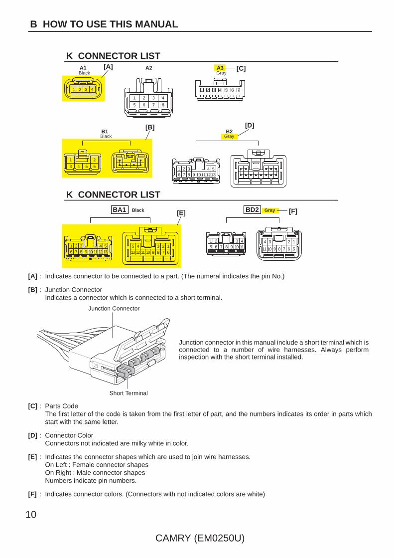
[A] : Indicates connector to be connected to a part. (The numeral indicates the pin No.)
[B] : Junction ConnectorIndicates a connector which is connected to a short terminal.
Junction Connector
Short Terminal
Junction connector in this manual include a short terminal which isconnected to a number of wire harnesses. Always performinspection with the short terminal installed.
[C] : Parts CodeThe first letter of the code is taken from the first letter of part, and the numbers indicates its order in parts whichstart with the same letter.
[D] : Connector ColorConnectors not indicated are milky white in color.
[E] : Indicates the connector shapes which are used to join wire harnesses.On Left : Female connector shapesOn Right : Male connector shapesNumbers indicate pin numbers.
[F] : Indicates connector colors. (Connectors with not indicated colors are white)

A1
L PART NUMBER OF CONNECTORS
Code
90980–11019
Part Number
B22 Door Courtesy SW (Front LH)
Code
90980–12470
A2 Inlet Air Temp. Sensor 90980–11163 B23 Front Seat Outer Belt (LH) 90980–12253
A3 Air Flow Meter 90980–12292 B24 Blower SW (Rear Heater) 90980–10463
A4 A/C Pressure Sensor 90980–10845
90980–10943
B25 Front Seat Outer Belt (RH) 90980–12253
A5 Pressure SW
90980–11156
B26 Door Courtesy SW (Front RH) 90980–12470
A6 Clearance Lamp (Front RH)
90980–11314
B27 Cooling Fan ECU No.1
A7 Headlamp (RH)
90980–11016
Cooling Fan ECU No.2
90980–10735A8 Headlamp Leveling Motor (RH)
90980–11252
Water Temp. Sensor (Radiator)
A9 Brake Vacuum Warning SW
90980–11207
Fuel Filter Warning SW
Brake Fluid Level Warning SW
90980–11599
Door Control Relay (LH)
90980–10121Windshield Washer Motor Step Lamp (LH)
Airbag Sensor (Front RH) Junction Connector
A10
A11
A12
A13 Airbag Squib90980–12490
Junction Connector 90980–11398
B28
B29
B30
B32
B33
B34
B35
Part NumberPart NamePart Name
[A] [B] [C]
Turn Signal Lamp (Front RH)
90980–11856
90980–10841
90980–11003
90980–10789
CAMRY (EM0250U)
11
B
[A] : Part Code
[B] : Part Name
[C] : Part NumberToyota Part Number are indicated.
Not all of the above part numbers of the connector are established for the supply.
To Ignition SWIG Terminal
Fuse
VoltmeterSW 1
Relay
SW 2 Solenoid
[A]
[B]
[C]
Ohmmeter
SW
Ohmmeter
Diode
Digital Type Analog Type
12
CAMRY (EM0250U)
C TROUBLESHOOTING
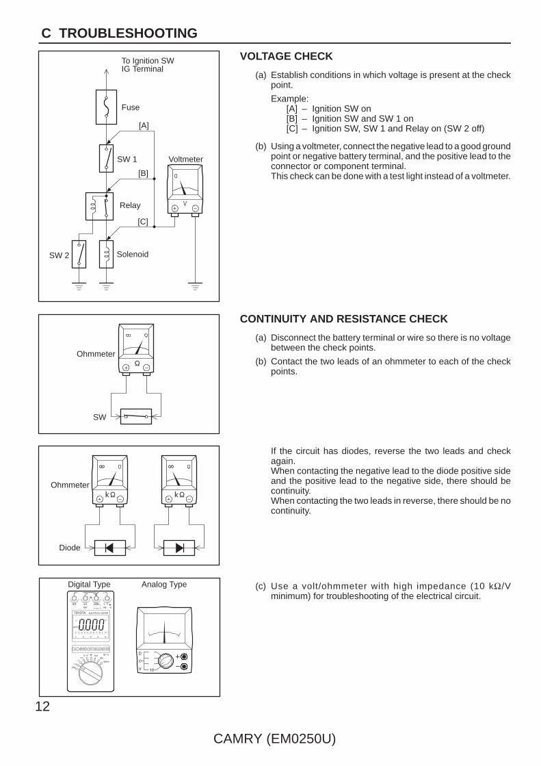
VOLTAGE CHECK
(a) Establish conditions in which voltage is present at the checkpoint.
Example:[A] – Ignition SW on[B] – Ignition SW and SW 1 on[C] – Ignition SW, SW 1 and Relay on (SW 2 off)
(b) Using a voltmeter, connect the negative lead to a good groundpoint or negative battery terminal, and the positive lead to theconnector or component terminal.This check can be done with a test light instead of a voltmeter.
CONTINUITY AND RESISTANCE CHECK
(a) Disconnect the battery terminal or wire so there is no voltagebetween the check points.
(b) Contact the two leads of an ohmmeter to each of the checkpoints.
If the circuit has diodes, reverse the two leads and checkagain.When contacting the negative lead to the diode positive sideand the positive lead to the negative side, there should becontinuity.When contacting the two leads in reverse, there should be nocontinuity.
(c) Use a volt/ohmmeter with high impedance (10 kΩ/Vminimum) for troubleshooting of the electrical circuit.
To Ignition SWIG Terminal
Test Light
RelayLight
SW 2 Solenoid
Disconnect
Short [A]
DisconnectDisconnect
SW 1
Fuse Case
Short [B]
Short [C]
Pull Up
Press Down Press Down
Pull Up
CAMRY (EM0250U)
13
C
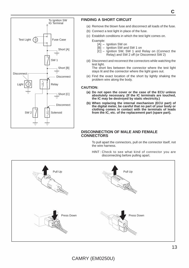
FINDING A SHORT CIRCUIT
(a) Remove the blown fuse and disconnect all loads of the fuse.
(b) Connect a test light in place of the fuse.
(c) Establish conditions in which the test light comes on.
Example:[A] – Ignition SW on[B] – Ignition SW and SW 1 on[C] – Ignition SW, SW 1 and Relay on (Connect the
Relay) and SW 2 off (or Disconnect SW 2)
(d) Disconnect and reconnect the connectors while watching thetest light.The short lies between the connector where the test lightstays lit and the connector where the light goes out.
(e) Find the exact location of the short by lightly shaking theproblem wire along the body.
CAUTION:(a) Do not open the cover or the case of the ECU unless
absolutely necessary. (If the IC terminals are touched,the IC may be destroyed by static electricity.)
(b) When replacing the internal mechanism (ECU part) ofthe digital meter, be careful that no part of your body orclothing comes in contact with the terminals of leadsfrom the IC, etc. of the replacement part (spare part).
DISCONNECTION OF MALE AND FEMALECONNECTORS
To pull apart the connectors, pull on the connector itself, notthe wire harness.
HINT : Check to see what kind of connector you aredisconnecting before pulling apart.

(mm)
Reference:
ToolUpExample:(Case 1)
Terminal Retainer
Terminal Retainer
[Retainer at Full Lock Position]
[Retainer at Temporary Lock Position]
StopperTerminalRetainer
SecondaryLocking Device
Example:(Case 2)
14
CAMRY (EM0250U)
C TROUBLESHOOTING
HOW TO REPLACE TERMINAL(with terminal retainer or secondary locking device)
1. PREPARE THE SPECIAL TOOL
HINT : To remove the terminal from the connector, pleaseconstruct and use the special tool or like object shown onthe left.
2. DISCONNECT CONNECTOR
3. DISENGAGE THE SECONDARY LOCKING DEVICE OR
TERMINAL RETAINER.
(a) Locking device must be disengaged before the terminallocking clip can be released and the terminal removed fromthe connector.
(b) Use a special tool or the terminal pick to unlock the secondarylocking device or terminal retainer.
NOTICE:Do not remove the terminal retainer from connector body.
[A] For Non–Waterproof Type Connector
HINT : The needle insertion position varies according to the
connector’s shape (number of terminals etc.), so
check the position before inserting it.
”Case 1”
Raise the terminal retainer up to the temporary lock
position.
”Case 2”
Open the secondary locking device.
ToolTab
Tab
TerminalRetainer
Access Hole( Mark)
Tool
Tool
[Female]
Example:
[Male]
(Case 1)
[Male] [Female]
Retainerat Full Lock Position
Retainerat Temporary Lock Position
Terminal Retainer
[Male] Press Down [Female]Press Down
ToolTool
Example:(Case 2)
CAMRY (EM0250U)
15
C
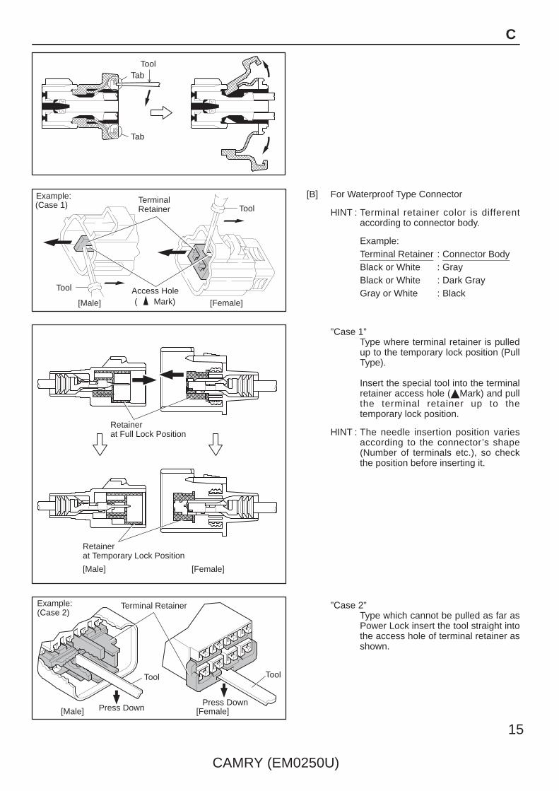
[B] For Waterproof Type Connector
HINT : Terminal retainer color is differentaccording to connector body.
Example:Terminal Retainer : Connector BodyBlack or White : GrayBlack or White : Dark GrayGray or White : Black
”Case 1”Type where terminal retainer is pulledup to the temporary lock position (PullType).
Insert the special tool into the terminalretainer access hole (Mark) and pullthe terminal retainer up to thetemporary lock position.
HINT : The needle insertion position variesaccording to the connector’s shape(Number of terminals etc.), so checkthe position before inserting it.
”Case 2”Type which cannot be pulled as far asPower Lock insert the tool straight intothe access hole of terminal retainer asshown.

Retainer atFull Lock Position
[Male] [Female]
Retainer atTemporary Lock Position
Locking Lug
Tool
16
CAMRY (EM0250U)
C TROUBLESHOOTING
Push the terminal retainer down to the temporary lock position.
(c) Release the locking lug from terminal and pull the terminal outfrom rear.
4. INSTALL TERMINAL TO CONNECTOR
(a) Insert the terminal.
HINT:1. Make sure the terminal is positioned correctly.2. Insert the terminal until the locking lug locks firmly.3. Insert the terminal with terminal retainer in the temporary lock
position.
(b) Push the secondary locking device or terminal retainer in tothe full lock position.
5. CONNECT CONNECTOR

∗ The titles given inside the components are the names of the terminals (terminal codes) and are not treated as beingabbreviations.
CAMRY (EM0250U)
17
ABBREVIATIONS D
ABBREVIATIONS
The following abbreviations are used in this manual.
A/C = Air Conditioning
A/T = Automatic Transaxle
ABS = Anti–Lock Brake System
ACIS = Acoustic Control Induction System
ACM = Active Control Engine Mount
CAN = Controller Area Network
EC = Electrochromic
ECU = Electronic Control Unit
ESA = Electronic Spark Advance
ETCS–i = Electronic Throttle Control System–intelligent
FL = Fusible Link
IC = Integrated Circuit
J/B = Junction Block
LCD = Liquid Crystal Display
LH = Left–Hand
M/T = Manual Transaxle
R/B = Relay Block
RH = Right–Hand
SFI = Sequential Multiport Fuel Injection
SRS = Supplemental Restraint System
SW = Switch
TEMP. = Temperature
TRAC = Traction Control
VSC = Vehicle Stability Control
VSV = Vacuum Switching Valve
VVT = Variable Valve Timing
VVT–i = Variable Valve Timing–intelligent
w/ = With
w/o = Without
18
CAMRY (EM0250U)
E GLOSSARY OF TERMS AND SYMBOLS
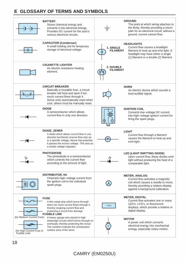
BATTERYStores chemical energy andconverts it into electrical energy.Provides DC current for the auto’svarious electrical circuits.
GROUNDThe point at which wiring attaches tothe Body, thereby providing a returnpath for an electrical circuit; without aground, current cannot flow.
CAPACITOR (Condenser)A small holding unit for temporarystorage of electrical voltage.
HEADLIGHTSCurrent flow causes a headlightfilament to heat up and emit light. Aheadlight may have either a single(1) filament or a double (2) filament
1. SINGLE FILAMENT
CIGARETTE LIGHTERAn electric resistance heatingelement.
2. DOUBLE FILAMENT
CIRCUIT BREAKERBasically a reusable fuse, a circuitbreaker will heat and open if toomuch current flows through it.Some units automatically reset whencool, others must be manually reset.
HORNAn electric device which sounds aloud audible signal.
DIODEA semiconductor which allowscurrent flow in only one direction.
IGNITION COILConverts low–voltage DC currentinto high–voltage ignition current forfiring the spark plugs.
DIODE, ZENERA diode which allows current flow in onedirection but blocks reverse flow only upto a specific voltage. Above that potential,it passes the excess voltage. This acts asa simple voltage regulator.
LIGHTCurrent flow through a filamentcauses the filament to heat up andemit light.
PHOTODIODEThe photodiode is a semiconductorwhich controls the current flowaccording to the amount of light.
LED (LIGHT EMITTING DIODE)Upon current flow, these diodes emitlight without producing the heat of acomparable light.
DISTRIBUTOR, IIAChannels high–voltage current fromthe ignition coil to the individualspark plugs.
METER, ANALOGCurrent flow activates a magneticcoil which causes a needle to move,thereby providing a relative displayagainst a background calibration.
FUSEA thin metal strip which burns throughwhen too much current flows through it,thereby stopping current flow andprotecting a circuit from damage.
FUSIBLE LINK
METER, DIGITALCurrent flow activates one or manyLED’s, LCD’s, or fluorescentdisplays, which provide a relative ordigital display.
FUEL
FUSIBLE LINKA heavy–gauge wire placed in highamperage circuits which burns through onoverloads, thereby protecting the circuit.The numbers indicate the crosssectionsurface area of the wires.
(for Medium Current Fuse)
(for High Current Fuse or Fusible Link)
MOTORA power unit which convertselectrical energy into mechanicalenergy, especially rotary motion.
M

CAMRY (EM0250U)
19
E
RELAYBasically, an electrically operatedswitch which may be normallyclosed (1) or open (2).Current flow through a small coilcreates a magnetic field which eitheropens or closes an attached switch.
1. NORMALLY CLOSED
2. NORMALLY OPEN
SWITCH, MANUALOpens and closescircuits, thereby
SPEAKERAn electromechanical device whichcreates sound waves from currentflow.
RELAY, DOUBLE THROWA relay which passes currentthrough one set of contacts or theother.
Opens and closescircuits, therebystopping (1) orallowing (2) currentflow.
1. NORMALLY OPEN
2. NORMALLY CLOSED
RESISTORAn electrical component with a fixedresistance, placed in a circuit toreduce voltage to a specific value.
SWITCH, DOUBLE THROWA switch which continuously passescurrent through one set of contactsor the other.
RESISTOR, TAPPEDA resistor which supplies two ormore different non adjustableresistance values.
SWITCH, IGNITIONA key operated switch with severalpositions which allows variouscircuits, particularly the primaryignition circuit, to becomeoperational.
RESISTOR, VARIABLE or RHEOSTATA controllable resistor with a variablerate of resistance.Also called a potentiometer orrheostat.
operational.
SENSOR (Thermistor)A resistor which varies its resistancewith temperature.
SWITCH, WIPER PARKAutomatically returns wipers to thestop position when the wiper switchis turned off.
(Reed Switch Type)
SENSOR, SPEEDUses magnetic impulses to openand close a switch to create a signalfor activation of other components.
TRANSISTORA solidstate device typically used asan electronic relay; stops or passescurrent depending on the voltageapplied at ”base”.
SHORT PINUsed to provide an unbrokenconnection within a junction block.
WIRESWires are always drawn asstraight lines on wiringdiagrams.Crossed wires (1) without ablack dot at the junction are
(1) NOT CONNECTED
SOLENOIDAn electromagnetic coil which formsa magnetic field when current flows,to move a plunger, etc.
black dot at the junction arenot joined;crossed wires (2) with ablack dot or octagonal ( )mark at the junction arespliced (joined)connections.
(2) SPLICED
20
CAMRY (EM0250U)
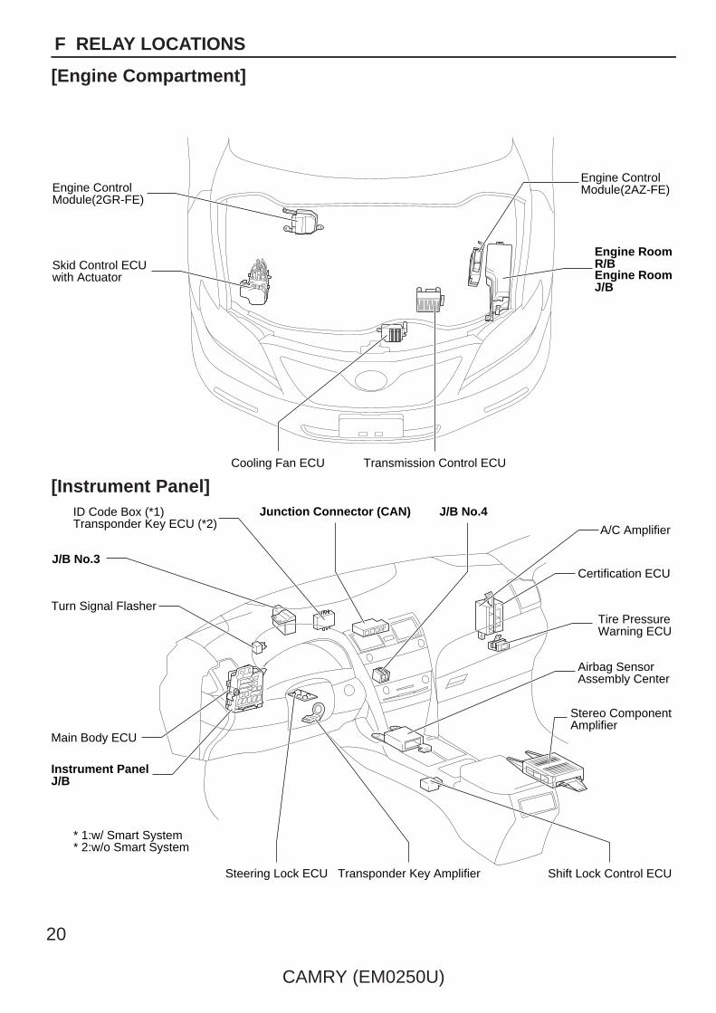
F RELAY LOCATIONS
[Engine Compartment]
Transmission Control ECU
Engine ControlModule(2AZ-FE)
Cooling Fan ECU
Engine RoomR/BEngine RoomJ/B
Skid Control ECUwith Actuator
Engine ControlModule(2GR-FE)
[Instrument Panel]
Shift Lock Control ECU
Tire PressureWarning ECU
Airbag SensorAssembly Center
Stereo ComponentAmplifier
A/C Amplifier
Certification ECU
Steering Lock ECU Transponder Key Amplifier
ID Code Box (*1)Transponder Key ECU (*2)
Main Body ECU
Turn Signal Flasher
J/B No.3
Instrument PanelJ/B
Junction Connector (CAN) J/B No.4
* 1:w/ Smart System* 2:w/o Smart System

CAMRY (EM0250U)
21
F
[Body]
Tire Pressure Warning Antenna and ReceiverOverhead J/B
Sliding Roof Control ECU and Motor Door Control Receiver
[Seat]
Occupant Classification ECU

35
1 2
35
1 2 1
2
3 5
1
1
35
1 2
35
1 2
351
2
1 2
3
H-LP (LH)
(from Engine Room Main Wire)Wire Color : W
(from Engine Room Main Wire)Wire Color : B
1
(from Engine Wire)Wire Color : B
Unit D
RR DEF Relay
IG2 Relay
ST CUT Relay
ST Relay
MGC RelayVSC NO.2 Relay
VSC No.1 Relay
Unit A
Unit B
* 1:120A ALT (for High Current)* 2:30A ST/AM2 (for High Current)* 3:50A HTR (for High Current)* 4:50A ABS No.1 (for High Current)* 5:50A FAN MAIN (for High Current)* 6:30A ABS No.2 (for High Current)* 7:50A RR DEF (for High Current)* 8:40A CDS FAN (for High Current)* 9:40A RDI FAN (for High Current)
EF
I MA
IN
15A
30A
H-LP (RH)15A
H-LP (LL)15A
H-LP (RL)15A
HORN10A
EFI NO.110A
MPX-B10AA/F20A
S-HORN7.5A
EFI NO.215A
EFI NO.310A
RADIO NO.115A
STR LOCK20AIG220AHAZ15A
ETCS
SHORT
10AECU-B NO.1
10ADOME10A
ALT-S7.5AAM27.5A
5
4
21
21
1 2
1 212
12
12
21
21
12
1 2
1 2
2
*9
*8
*7
*6
*5
*4
*3
*1
*2
1
AM
P25
A
2
1
DO
OR
NO
.125
A
2
1
Unit C Unit E
1G
1F
1C
22
CAMRY (EM0250U)
F RELAY LOCATIONS
1 : Engine Room R/BEngine Compartment Left (See Page 20)
: Engine Room J/BEngine Compartment Left (See Page 20)

Unit E
1
2
3 5
4 35
1
2
35
1
2
35
1
2
FAN MAIN Relay
2GR-FE
FAN NO.1 Relay
2AZ-FE
FAN NO.3 Relay
FAN NO.2 Relay
CAMRY (EM0250U)
23
F
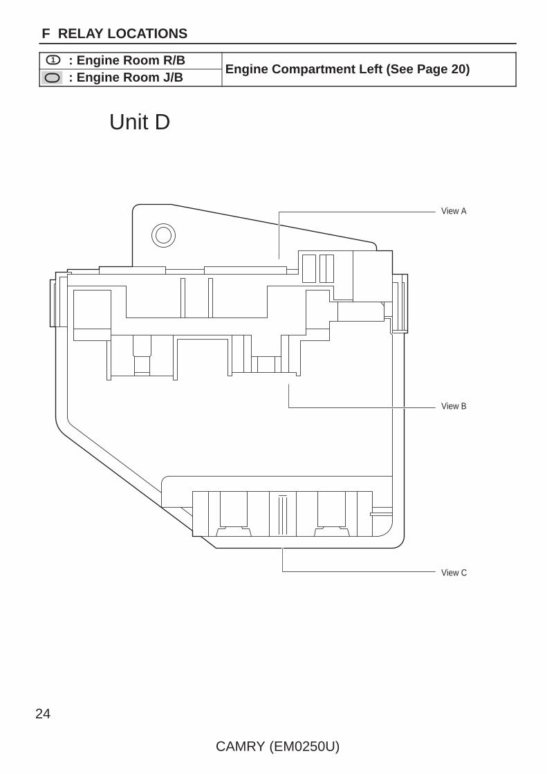
View A
View B
View C
Unit D
24
CAMRY (EM0250U)
F RELAY LOCATIONS
1 : Engine Room R/BEngine Compartment Left (See Page 20)
: Engine Room J/BEngine Compartment Left (See Page 20)
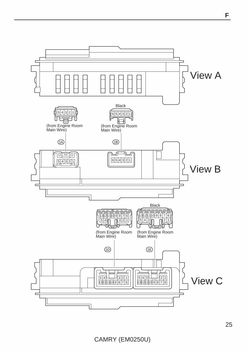
123456789
5 4 3 2 169 8 7
123456789
12345678910111213
1011121310111213
10111213
12345 123456
12345 123456
View A
View B
(from Engine Room Main Wire)
(from Engine Room Main Wire)
Black
Black
(from Engine Room Main Wire)
(from Engine Room Main Wire)
View C
1A
1D 1E
1B
CAMRY (EM0250U)
25
F

21
1
1
1
1
1
1
1
1
1
1
15A EFI NO.2
10A EFI NO.3
15A RADIO NO.1
10A ECU-B NO.1SHORT
10A DOME
7.5A AM2
7.5A ALT-S
10A ETCS
15A HAZ
20A IG2
25A AMP
25A DOOR NO.1
20A STR LOCK
30A EFI MAIN
1
2
2
2
2
2
2
2
2
2
2
2
1 2
1 2
21
(Cont. Next Page)
Unit C
1 1
1
1
1
1
1
1
1
1
1
1
1
1
1
1
1
1
1
1
1
1 1G
26
CAMRY (EM0250U)
F RELAY LOCATIONS
[Engine Room R/B and Engine Room J/B Inner Circuit]

30A ST/AM2
50A HTR
120AALT
50A ABS No.1
50A FAN MAIN
30A ABS No.2
50A RR DEF
40A CDS FAN
40A RDI FAN
Unit A
Unit B
1 1C
1 1F
1
1
1
1
1
1
1
1
1
1
1
1
1
1
1
1
1
1
(Cont. Next Page)
(Cont'd)
CAMRY (EM0250U)
27
F
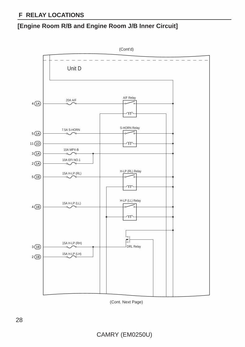
Unit D
20A A/FA/F Relay
S-HORN Relay
H-LP (RL) Relay
H-LP (LL) Relay
DRL Relay
7.5A S-HORN
10A MPX-B
10A EFI NO.1
15A H-LP (RL)
15A H-LP (LL)
15A H-LP (RH)
15A H-LP (LH)
4 1A
5 1A
11 1D
3 1A
2 1A
5 1B
4 1B
3 1B
2 1B
(Cont'd)
(Cont. Next Page)
28
CAMRY (EM0250U)
F RELAY LOCATIONS
[Engine Room R/B and Engine Room J/B Inner Circuit]
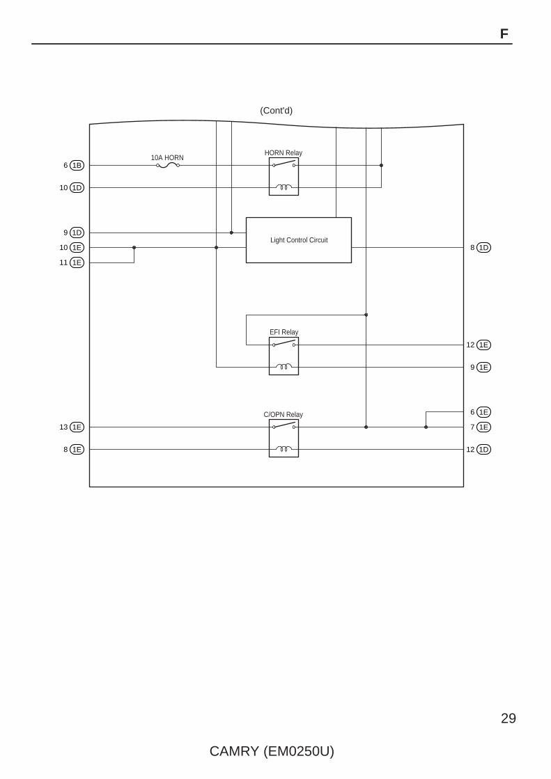
10A HORNHORN Relay
EFI Relay
C/OPN Relay
Light Control Circuit
6 1B
10 1D
8 1D
12 1E
9 1E
6 1E
7 1E
12 1D
9 1D
10 1E
11 1E
13 1E
8 1E
(Cont'd)
CAMRY (EM0250U)
29
F

123456789
123410
10
10
10
10
10
10
10
11
11
10
10
11
11
1112
12
12
12
10
10
10
10
10
11
11
11
11
11
12
12
13
13
14
14
121314
11121314
15
15
16
16
15
15
16
16
17
17
18
18
19
19
20
20
(from Instrument Panel Wire)
(from Instrument Panel Wire)
Yellow
(from Instrument Panel Wire)
(from Instrument Panel Wire)
(from Instrument Panel Wire)
(from Floor Wire)
(from Floor Wire)
IG1 RelayPWR RelayACC Relay
(from Instrument Panel Wire)
(from Instrument Panel Wire)
(from Engine Room Main Wire)
(from Engine Room Main Wire)
(from Engine Room Main Wire)
(from Engine Room Main Wire)
FOG Relay
TAIL Relay
11
11
12
12
10
10
11
11
12
12
56789
123456789
4 6 7 8 2 9875 6431
10
10
11
11
12
12
12
12
13
13
13
13
13
13
14
14
14
14
13
13
14
14
15
15
15
15
16
16
16
16
17
17
18
18
19
19
20
20
2 9875 6431
95321
97321
84 5 6
10
10
11
11
12
12
12
101112
97321
8
7 8
4 5 6
1
87
64 5
64 5
32
1 32
8321
9
9
94 5 6 7
121
1 2
1
1 2 3 4 5 67 8 9
1 2 3 4 5 67 8 9
1 2 3 4 5 67 8 9
2 1
53
2 1
53
2
3
5
1 2
3
5
1
123456789
123456789
123456789
123456789
123456789
1236789
45
123456789
123456789
35
124
IM
IJ
IE
IF
IR
IO
IP
IK
IL
IC
ID
IB
IA
30
CAMRY (EM0250U)
F RELAY LOCATIONS
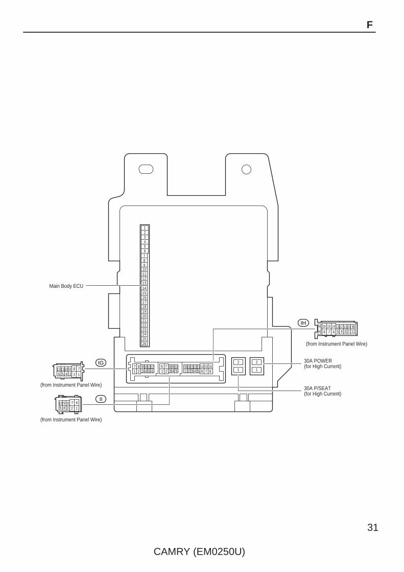
: Instrument Panel J/B Cowl Side Left (See Page 20)
3 5 6 83 765427 910 101112 10
10
11
11
12
12
13
13
14
14
15
15
16
16
4218
196
538
4217 9
2
1
2
1
123456789
1011121314Main Body ECU
(from Instrument Panel Wire)
(from Instrument Panel Wire)
30A POWER(for High Current)
30A P/SEAT(for High Current)
(from Instrument Panel Wire)
151617181920212223242526
12345678910
10
1112
12346789
5
123456789
IG
IH
II
CAMRY (EM0250U)
31
F

RR
DO
OR
RH
RR
DO
OR
LH
25A
EC
U IG
NO
.110
A
A/C
NO
.210
A
GA
UG
E N
O.2
7.5A
EC
U-A
CC
7.5A
RA
DIO
NO
.27.
5AM
IR H
TR10
A
PW
R O
UTL
ET
20A
WA
SH
10A
S-H
TR20
A
EC
U IG
NO
.27.
5A
GA
UG
E N
O.1
10A
INJ
15A
IGN
10A
WIP
25A
25A
PW
R25
A
AM
17.
5A A/C
7.5A
PA
NE
L7.
5A
DO
OR
NO
.225
AS
/RO
OF
30A
TAIL
15A
FR F
OG
15A
OB
D7.
5A
STO
P10
A
32
CAMRY (EM0250U)
F RELAY LOCATIONS
: Instrument Panel J/B Cowl Side Left (See Page 20)
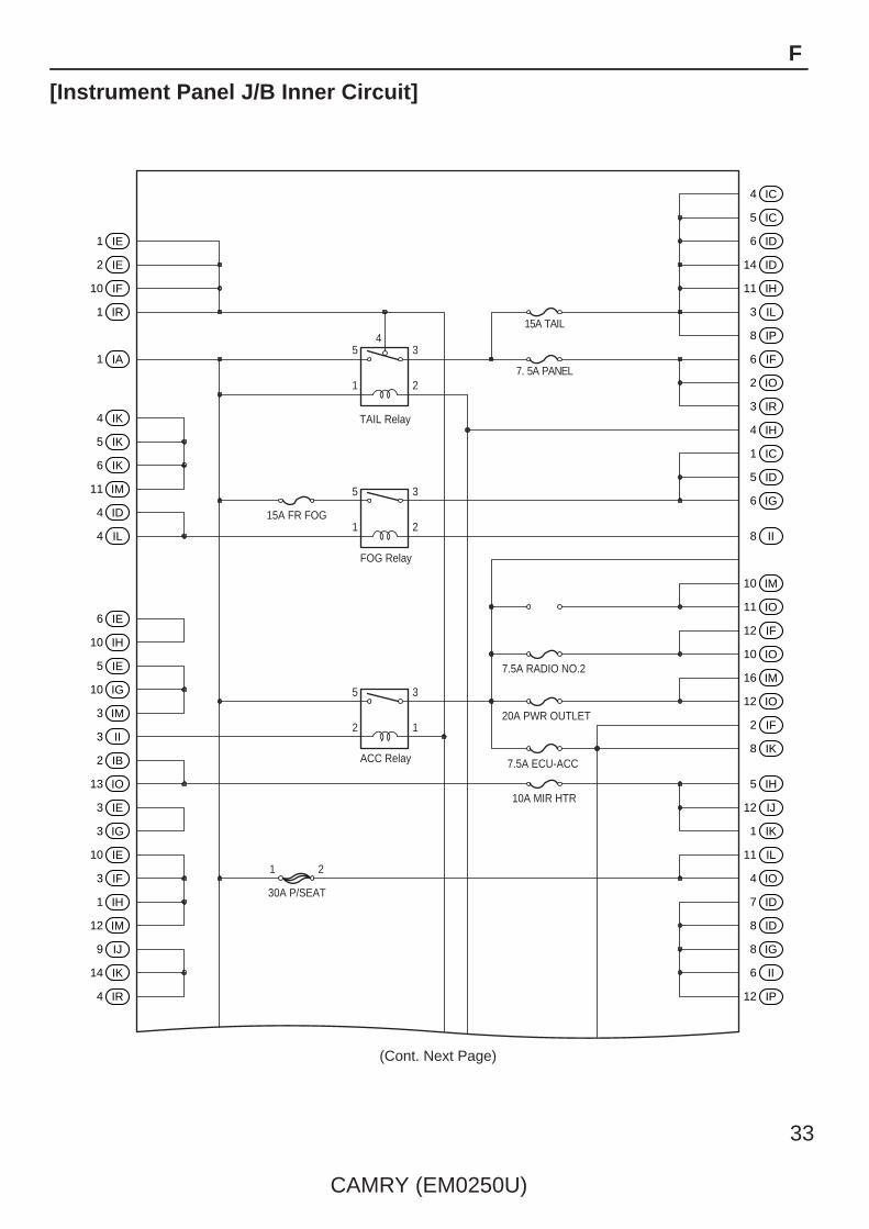
15A TAIL
7. 5A PANEL
45
1
5
1
5
2
3
2
TAIL Relay
15A FR FOG
FOG Relay
ACC Relay
7.5A RADIO NO.2
20A PWR OUTLET
7.5A ECU-ACC
10A MIR HTR
30A P/SEAT
3
2
3
1
1 2
(Cont. Next Page)
1 IE
2 IE
10 IF
1 IR
1 IA
4 IK
5 IK
6 IK
11 IM
4 ID
4 IL
6 IE
10 IH
5 IE
10 IG
3 IM
3 II
2 IB
13 IO
3 IE
3 IG
10 IE
3 IF
1 IH
12 IM
9 IJ
14 IK
4 IR
4 IC
5 IC
6 ID
14 ID
11 IH
3 IL
8 IP
6 IF
2 IO
3 IR
4 IH
1 IC
5 ID
6 IG
8 II
10 IM
11 IO
12 IF
10 IO
16 IM
12 IO
2 IF
8 IK
5 IH
12 IJ
1 IK
11 IL
4 IO
7 ID
8 ID
8 IG
6 II
12 IP
CAMRY (EM0250U)
33
F
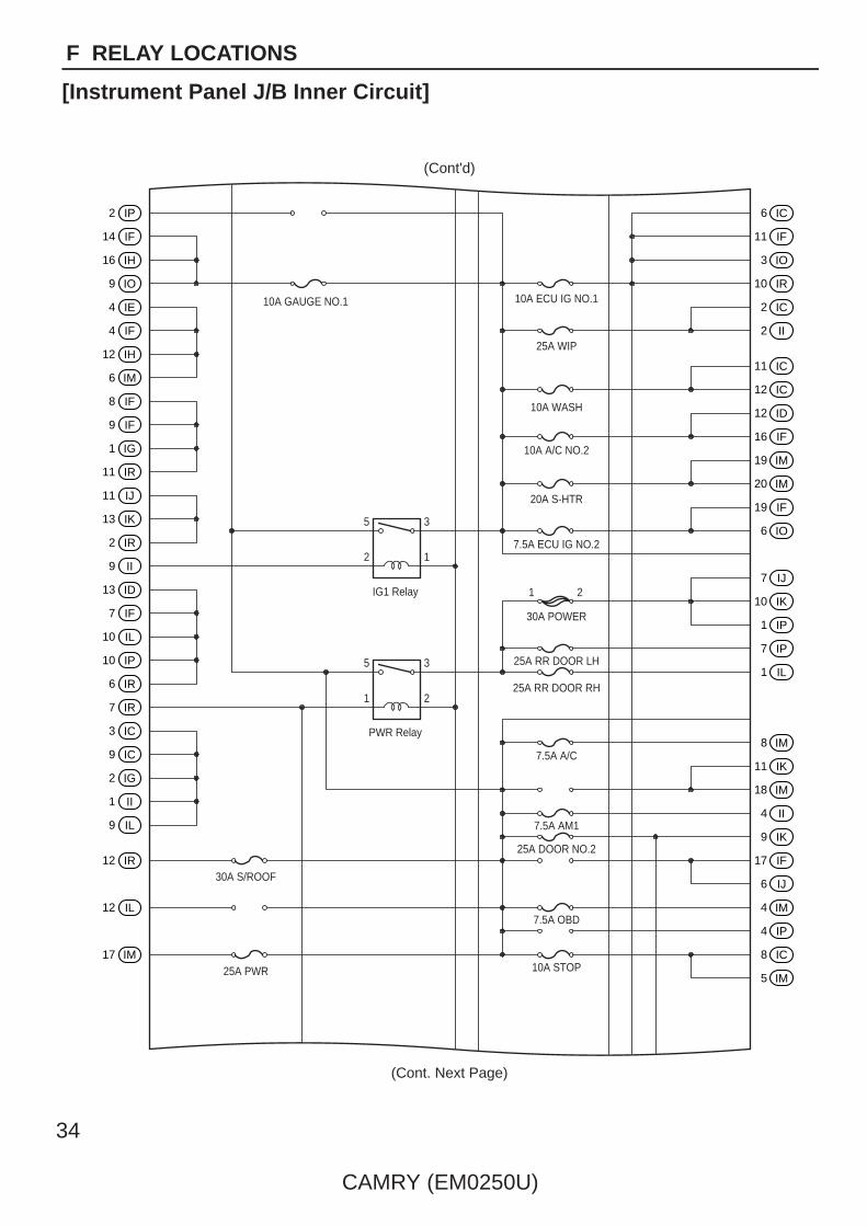
[Instrument Panel J/B Inner Circuit]
3
10A GAUGE NO.1 10A ECU IG NO.1
10A WASH
10A A/C NO.2
20A S-HTR
30A POWER
25A RR DOOR LH
25A RR DOOR RH
7.5A A/C
7.5A AM1
7.5A OBD
10A STOP
25A DOOR NO.2
7.5A ECU IG NO.2
25A WIP
IG1 Relay
PWR Relay
30A S/ROOF
25A PWR
1
5
2
1 2
1
5
2
3
(Cont'd)
(Cont. Next Page)
2 IP
14 IF
16 IH
9 IO
4 IE
4 IF
12 IH
6 IM
8 IF
9 IF
1 IG
11 IR
11 IJ
13 IK
2 IR
9 II
13 ID
7 IF
10 IL
10 IP
6 IR
7 IR
3 IC
9 IC
2 IG
1 II
9 IL
12 IR
12 IL
17 IM
6 IC
11 IF
3 IO
10 IR
2 IC
2 II
11 IC
12 IC
12 ID
16 IF
19 IM
20 IM
19 IF
6 IO
7 IJ
10 IK
1 IP
7 IP
1 IL
8 IM
11 IK
18 IM
4 II
9 IK
17 IF
6 IJ
4 IM
4 IP
8 IC
5 IM
34
CAMRY (EM0250U)
F RELAY LOCATIONS
[Instrument Panel J/B Inner Circuit]

5 7
26BECU (*2)
HORN
LSWL (*1)LSR (*2)
LCTY
LIN1UL1 PWS HU UL2STP TRLY ACT+
7.5A GAUGE NO.2
10A IGN
15A INJ
BATB(*1)
IGPKBACT- ILE GND1
Main Body ECU
ACC
ALTB
GND2
HRLY
L1
L2
DRL
25
20
17
16
14
12 18 21 13 23 24 22 15
10
11
19
6
4
8
9
13 2
(Cont'd)
13 IF 7 IC
14 IC
4 IG
3 IH
2 IM
12 IG
1 ID
9 IE
9 IG
2 IH
13 IM
14 IM
8 IO
11 IG
7 IH
8 IH
5 IF
1 IJ
11 IP
2 IK
16 ID
15 IH
9 IM
3 ID
13 IH
3 IJ
15 IK
5 IJ
16 IK
9 ID
7 IK
9 IP
13 IC
15 IF
7 IL
7 IM
3 IP
7 II
10 IC
15 ID
5 IG
10 II
1 IM
5 IR
18 IF
2 IJ
6 IP
4 IJ
12 IK
7 IE
9 IR
8 IE
6 IL
7 IO
5 IL
5 IP
11 ID
5 II
1 IF
10 ID
*1:w/ Smart Key System*2:w/o Smart Key System
CAMRY (EM0250U)
35
F

7 49 58 6
1
(from Instrument Panel No.2 Wire)
(from Instrument Panel No.2 Wire)
(from Instrument Panel Wire)
(from Instrument Panel Wire)
(from Instrument Panel Wire)
(from Instrument Panel Wire)
(from Instrument Panel Wire)
(from Instrument Panel Wire)
(from Instrument Panel Wire)
(from Instrument Panel Wire)
(from Instrument Panel Wire)
(from Instrument Panel Wire)
(from Instrument Panel Wire)
(from Instrument Panel Wire)
(from Instrument Panel Wire)
(from Instrument Panel Wire)
(from Instrument Panel Wire)
(from Instrument Panel No.2 Wire)
Gray
Gray
Gray
Gray
Gray
Gray
Gray
Gray
Gray
(from Instrument Panel No.2 Wire)
(from Instrument Panel No.2 Wire)
(from Instrument Panel No.2 Wire)
2 3 4 5 6 7 8 9 10 11 12
101112 123
7 49 58 6101112 123
7 49 58 6101112 123
6 94 85 7 10 11 121 2 3
6 94 85 7 10 11 121 2 3
6 94 85 7 10 11 121 2 3
6 94 85 7 10 11 121 2 3
6 94 85 7 10 11 121 2 3
6 94 85 7 10 11 121 2 3
6 94 85 7 10 11 121 2 3
6 94 85 7 10 11 121 2 3
6 94 85 7 10 11 121 2 3
6 94 85 7 10 11 121 2 3
6 94 85 7 10 11 121 2 3
6 94 85 7 10 11 121 2 3
6 94 85 7 10 11 121 2 3
6 94 85 7 10 11 121 2 3
6 94 85 7 10 11 121 2 3
6 94 85 7 10 11 121 2 3
6 94 85 7 10 11 121 2 3
6 94 85 7 10 11 121 2 3
1 2 3 4 5 6 7 8 9 10 11 12
1 2 3 4 5 6 7 8 9 10 11 12
9 8 7 6 5 4 3 2 112 11 10
9 8 7 6 5 4 3 2 112 11 10
9 8 7 6 5 4 3 2 112 11 10
9 8 7 6 5 4 3 2 112 11 10
9 8 7 6 5 4 3 2 112 11 10
9 8 7 6 5 4 3 2 112 11 10
9 8 7 6 5 4 3 2 112 11 10
9 8 7 6 5 4 3 2 112 11 10
9 8 7 6 5 4 3 2 112 11 10
9 8 7 6 5 4 3 2 112 11 10
9 8 7 6 5 4 3 2 112 11 10
9 8 7 6 5 4 3 2 112 11 10
9 8 7 6 5 4 3 2 112 11 10
9 8 7 6 5 4 3 2 112 11 10
9 8 7 6 5 4 3 2 112 11 10
9 8 7 6 5 4 3 2 112 11 10
9 8 7 6 5 4 3 2 112 11 10
9 8 7 6 5 4 3 2 112 11 10
3Q
3S
3U
3B
3D
3F
3H
3J
3L
3N
3P
3R
3T
3A
3C
3E
3G
3I
3K
3M
3O
36
CAMRY (EM0250U)
F RELAY LOCATIONS
: J/B No.3 Behind the Combination Meter (See Page 20)

CAMRY (EM0250U)
37
Memo

2 3P
10 3N
3 3P
10 3T
9 3T
10 3U
9 3U
10 3B
9 3J
10 3M
10 3O
4 3P
11 3C
5 3P
8 3G
8 3H
6 3P
7 3O
7 3P
7 3F
7 3G
8 3P
6 3E
9 3P
3 3B
11 3P
3 3D
5 3C
5 3K
4 3K
5 3L
5 3I
5 3O
(Cont. Next Page)
10 3P
3 3J
2 3J
1 3Q
1 3R
12 3B
11 3G
12 3H
12 3I
12 3L
2 3Q
10 3K
10 3L
12 3N
3 3Q
11 3J
4 3Q
4 3R
11 3S
11 3T
12 3U
11 3U
9 3B
9 3C
5 3Q
11 3A
10 3D
11 3H
10 3H
6 3Q
6 3A
7 3J
7 3M
38
CAMRY (EM0250U)
F RELAY LOCATIONS
[J/B No.3 Inner Circuit]
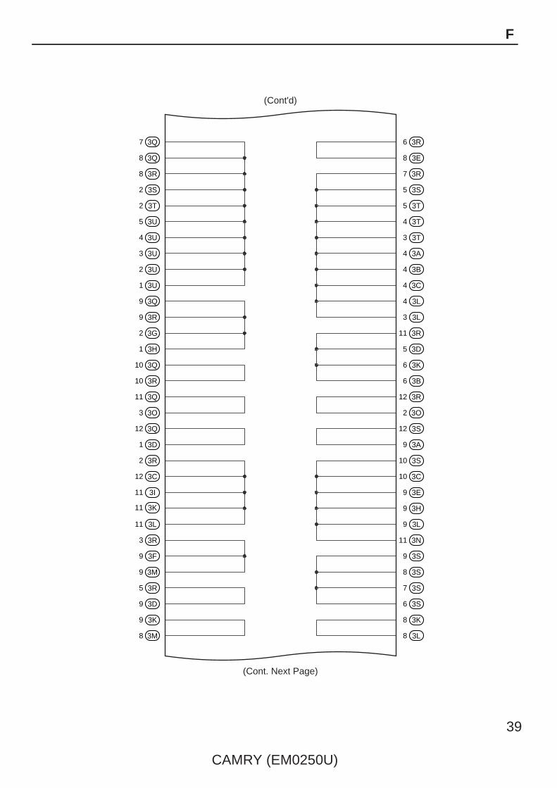
7 3Q
8 3Q
8 3R
2 3S
2 3T
5 3U
4 3U
3 3U
2 3U
1 3U
9 3Q
9 3R
2 3G
1 3H
10 3Q
10 3R
11 3Q
3 3O
12 3Q
1 3D
2 3R
12 3C
11 3I
11 3K
11 3L
3 3R
9 3F
9 3M
5 3R
9 3D
9 3K
8 3M
(Cont'd)
(Cont. Next Page)
6 3R
8 3E
7 3R
5 3S
5 3T
4 3T
3 3T
4 3A
4 3B
4 3C
4 3L
3 3L
11 3R
5 3D
6 3K
6 3B
12 3R
2 3O
12 3S
9 3A
10 3S
10 3C
9 3E
9 3H
9 3L
11 3N
9 3S
8 3S
7 3S
6 3S
8 3K
8 3L
CAMRY (EM0250U)
39
F

4 3S
3 3M
3 3S
3 3A
1 3S
2 3C
1 3L
1 3M
12 3T
10 3A
8 3T
8 3A
7 3T
6 3T
7 3U
6 3U
6 3L
1 3T
1 3A
8 3U
7 3D
7 3A
7 3B
5 3J
5 3B
5 3H
6 3O
1 3B
1 3C
1 3J
(Cont'd)
(Cont. Next Page)
12 3A
11 3F
10 3F
12 3O
11 3O
5 3A
6 3C
5 3G
5 3N
4 3I
2 3A
2 3B
3 3F
3 3G
6 3H
3 3H
3 3I
2 3K
1 3K
2 3M
1 3N
1 3O
3 3C
11 3B
12 3E
8 3B
8 3C
7 3K
7 3L
8 3N
40
CAMRY (EM0250U)
F RELAY LOCATIONS
[J/B No.3 Inner Circuit]

7 3C
7 3I
6 3N
12 3D
6 3M
11 3D
11 3M
8 3D
6 3D
7 3E
6 3F
6 3J
4 3D
4 3O
2 3D
2 3N
11 3E
10 3J
10 3E
12 3M
5 3E
5 3F
4 3E
4 3H
3 3E
3 3K
2 3E
4 3M
1 3E
4 3N
(Cont'd)
12 3F
12 3J
12 3K
8 3F
9 3O
8 3O
4 3F
4 3J
2 3F
3 3N
1 3F
2 3L
12 3G
9 3N
10 3G
10 3I
9 3G
4 3G
9 3I
6 3G
6 3I
1 3G
2 3I
1 3I
7 3H
8 3J
2 3H
5 3M
8 3I
7 3N
CAMRY (EM0250U)
41
F
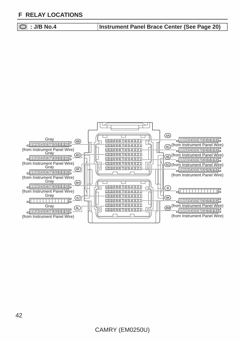
7 4 19 2358 6
(from Instrument Panel Wire)(from Instrument Panel Wire)
(from Instrument Panel Wire)
(from Instrument Panel Wire)
(from Instrument Panel Wire)
(from Instrument Panel Wire)
(from Instrument Panel Wire)
(from Instrument Panel Wire)
(from Instrument Panel Wire)
(from Instrument Panel Wire)
(from Instrument Panel Wire)
1011127 4 19 2358 61011127 4 19 2358 61011127 4 19 2358 61011127 4 19 2358 61011127 4 19 2358 6101112
7 4 19 2358 6101112
7 4 19 2358 61011127 4 19 2358 61011127 4 19 2358 61011127 4 19 2358 61011127 4 19 2358 61011127 4 19 2358 6101112
1 2 3 4 5 6 7 8 9 101112
1 2 3 4 5 6 7 8 9 101112
1 2 3 4 5 6 7 8 9 101112
1 2 3 4 5 6 7 8 9 101112
1 2 3 4 5 6 7 8 9 101112
1 2 3 4 5 6 7 8 9 101112
4A
4C
4E
4G
4I
4K
4M4L
4J
4H
4F
4D
4B1 2 3 4 5 6 7 8 9 101112
1 2 3 4 5 6 7 8 9 101112
1 2 3 4 5 6 7 8 9 101112
1 2 3 4 5 6 7 8 9 101112
1 2 3 4 5 6 7 8 9 101112
Gray
Gray
Gray
Gray
Gray
Gray
42
CAMRY (EM0250U)
F RELAY LOCATIONS
: J/B No.4 Instrument Panel Brace Center (See Page 20)

12 4D
11 4H
12 4H
12 4K
12 4L
1 4A
1 4D
1 4E
2 4E
1 4G
1 4I
4 4A
5 4D
6 4F
6 4I
11 4B
11 4I
12 4I
11 4M
12 4B
9 4D
10 4D
11 4D
10 4J
10 4K
11 4K
2 4D
1 4F
2 4F
11 4A
12 4C
8 4B
9 4B
10 4B
8 4C
8 4D
10 4H
11 4J
12 4J
4 4I
5 4I
6 4K
3 4B
4 4B
5 4B
4 4D
4 4H
3 4J
4 4J
5 4J
3 4A
3 4I
7 4A
7 4L
12 4E
12 4G
12 4M
4 4E
5 4E
5 4H
4 4L
5 4L
(Cont. Next Page)
CAMRY (EM0250U)
43
F
[J/B No.4 Inner Circuit]
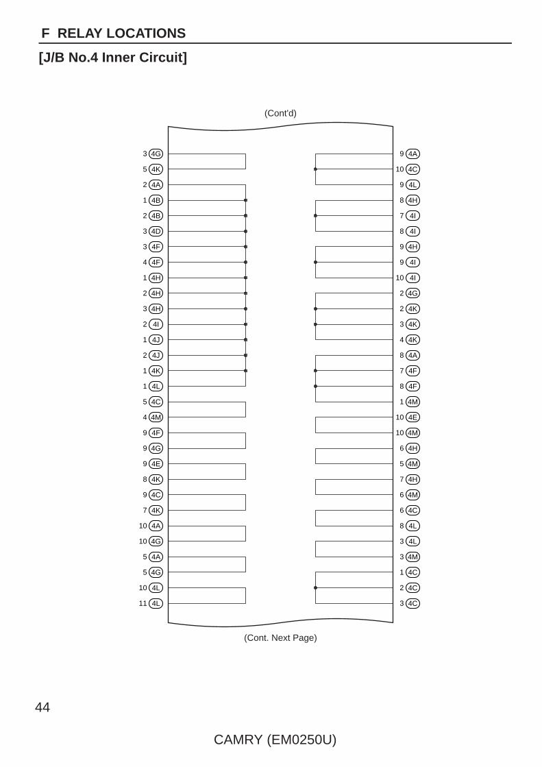
3 4G
5 4K
2 4A
1 4B
2 4B
3 4D
3 4F
4 4F
1 4H
2 4H
3 4H
2 4I
1 4J
2 4J
1 4K
1 4L
5 4C
4 4M
9 4F
9 4G
9 4E
8 4K
9 4C
7 4K
10 4A
10 4G
5 4A
5 4G
10 4L
11 4L
9 4A
10 4C
9 4L
8 4H
7 4I
8 4I
9 4H
9 4I
10 4I
2 4G
2 4K
3 4K
4 4K
8 4A
7 4F
8 4F
1 4M
10 4E
10 4M
6 4H
5 4M
7 4H
6 4M
6 4C
8 4L
3 4L
3 4M
1 4C
2 4C
3 4C
(Cont. Next Page)
(Cont'd)
44
CAMRY (EM0250U)
F RELAY LOCATIONS
[J/B No.4 Inner Circuit]
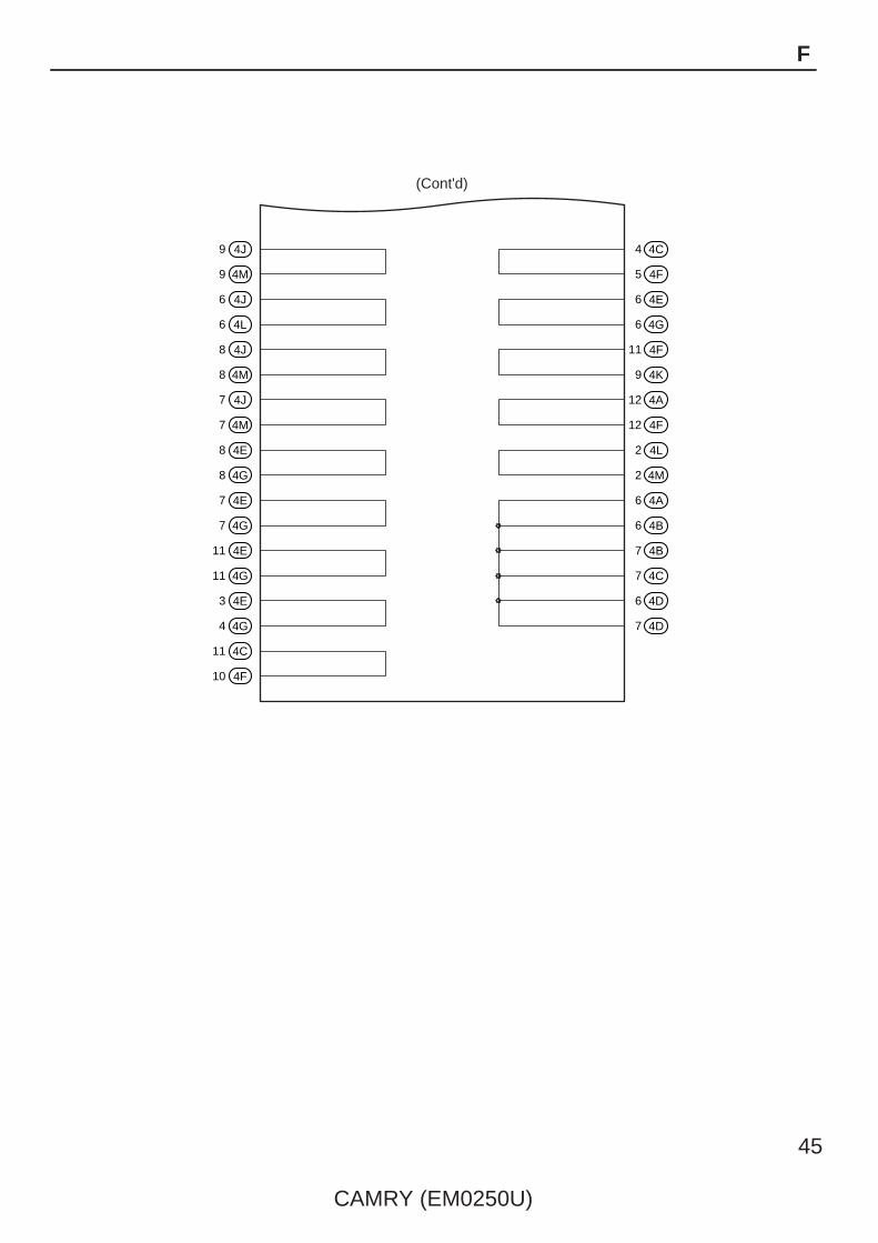
9 4J 4 4C
5 4F
6 4E
6 4G
11 4F
9 4K
12 4A
12 4F
2 4L
2 4M
6 4A
6 4B
7 4B
7 4C
6 4D
7 4D
9 4M
6 4J
6 4L
8 4J
8 4M
7 4J
7 4M
8 4E
8 4G
7 4E
7 4G
11 4E
11 4G
3 4E
4 4G
11 4C
10 4F
(Cont'd)
CAMRY (EM0250U)
45
F

1
E42
E44Black
E45Black
2 2
1
2
1
2
1
2
1
2
1
2
1
1
2
1
2
1
2
E43
1
2
E63Brown
1
2
E62Gray
1
2
E46Blue
1
2
46
CAMRY (EM0250U)
F RELAY LOCATIONS
Junction Connector (CAN) Instrument Panel Brace Center (See Page 20)
1
1
1
1
1
2
2
2
2
2
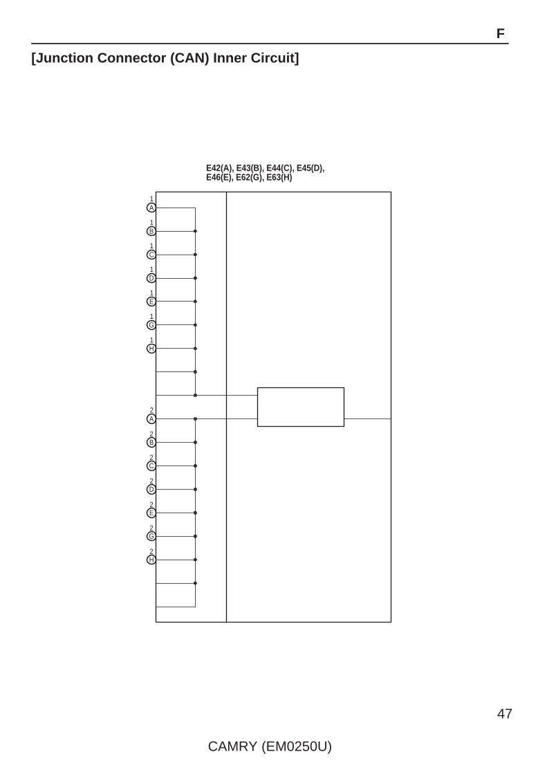
E42(A), E43(B), E44(C), E45(D), E46(E), E62(G), E63(H)
A
B
C
D
E
1
1
G
H
A
B
C
D
E
2G
2H
CAMRY (EM0250U)
47
F
[Junction Connector (CAN) Inner Circuit]
48
CAMRY (EM0250U)
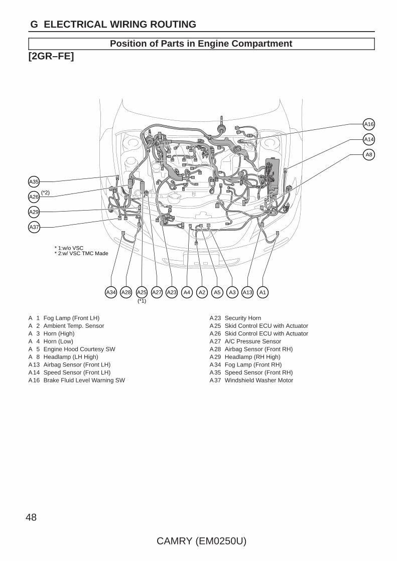
G ELECTRICAL WIRING ROUTING
Position of Parts in Engine Compartment[2GR–FE]
A14
A16
A8
A2A4A23 A3A5 A13 A1
A37
A27A25A28A34
A29
A35
A26
(*1)
(*2)
* 1:w/o VSC* 2:w/ VSC TMC Made
A 1 Fog Lamp (Front LH)A 2 Ambient Temp. SensorA 3 Horn (High)A 4 Horn (Low)A 5 Engine Hood Courtesy SWA 8 Headlamp (LH High)A13 Airbag Sensor (Front LH)A14 Speed Sensor (Front LH)A16 Brake Fluid Level Warning SW
A23 Security HornA25 Skid Control ECU with ActuatorA26 Skid Control ECU with ActuatorA27 A/C Pressure SensorA28 Airbag Sensor (Front RH)A29 Headlamp (RH High)A34 Fog Lamp (Front RH)A35 Speed Sensor (Front RH)A37 Windshield Washer Motor

CAMRY (EM0250U)
49
G
Position of Parts in Engine Compartment[2GR–FE]
A60
A55
A51
A50
A49
A47
A59
B1
A46
A45
A48
A43
A52 A54 A53
(*4)
(*5)
(*3)
* 3:w/ VSC TMMK Made* 4:TMC Made* 5:TMMK Made
A43 Junction ConnectorA45 Headlamp (LH Low)A46 Turn Signal and Parking Lamp (Front LH)A47 Side Marker Lamp (Front LH)A48 Wireless Door Lock BuzzerA49 Headlamp (RH Low)A50 Turn Signal and Parking Lamp (Front RH)A51 Side Marker Lamp (Front RH)A52 Washer Level Warning SWA53 VSV (Air Intake Control)A54 Cooling Fan ECUA55 Engine Control ModuleA59 Windshield Wiper MotorA60 Skid Control ECU with Actuator
B 1 Windshield Wiper Motor

50
CAMRY (EM0250U)
G ELECTRICAL WIRING ROUTING
Position of Parts in Engine Compartment[2GR–FE]
C7
C8
C13
C4
C1
C10
C2
C6
C3
C14
C17 C11 C12 C16 C15 C5
C23 C21 C18 C19
C9
C 1 Park/Neutral Position SWC 2 Mass Air Flow MeterC 3 StarterC 4 Engine Coolant Temp. SensorC 5 Throttle Body AssemblyC 6 VSV (Purge)C 7 Fuel Injector (No.1)C 8 Fuel Injector (No.3)C 9 Fuel Injector (No.2)C10 Fuel Injector (No.4)C11 Ignition Coil (No.1)
C12 Ignition Coil (No.3)C13 Ignition Coil (No.2)C14 Ignition Coil (No.4)C15 Air Fuel Ratio Sensor (Bank 1 Sensor 1)C16 Noise Filter (Ignition RH)C17 Power Steering Oil Pressure SWC18 GeneratorC19 GeneratorC21 A/C CompressorC23 Engine Oil Pressure SW

CAMRY (EM0250U)
51
G
Position of Parts in Engine Compartment[2GR–FE]
C48
C41
C43
C42
C47
C45
C46
C35
C49
C37
C39
C56
C55 C40 C36 C38 C57
C52 C51C50C53 C44 C34 D1
V1
V2
C34 VSV (ACM)C35 Air Fuel Ratio Sensor (Bank 2 Sensor 1)C36 Fuel Injector (No.5)C37 Fuel Injector (No.6)C38 Ignition Coil (No.5)C39 Ignition Coil (No.6)C40 VVT Sensor (Bank 1 Exhaust Side)C41 VVT Sensor (Bank 1 Intake Side)C42 Camshaft Timing Oil Control Valve (RH Exhaust Side)C43 Camshaft Timing Oil Control Valve (RH Intake Side)C44 VVT Sensor (Bank 2 Exhaust Side)C45 VVT Sensor (Bank 2 Intake Side)C46 Camshaft Timing Oil Control Valve (LH Exhaust Side)C47 Camshaft Timing Oil Control Valve (LH Intake Side)C48 VSV (ACIS)C49 Noise Filter (Ignition LH)C50 Crankshaft Position SensorC51 Heated Oxygen Sensor (Bank 2 Sensor 2)C52 Heated Oxygen Sensor (Bank 1 Sensor 2)C53 A/C CompressorC55 Engine Control ModuleC56 Transmission Control ECUC57 Junction Connector
D 1 Starter
V 1 Knock Control Sensor (Bank 2)V 2 Knock Control Sensor (Bank 1)

52
CAMRY (EM0250U)
G ELECTRICAL WIRING ROUTING
Position of Parts in Engine Compartment[2AZ–FE]
A14
A24
A16
A8
A2A4A23 A3A5 A13A7 A1
A37
A27A25A28A34
A29
A35
A26
A6
(*1)
(*2)
* 1:w/o VSC* 2:w/ VSC TMC Made
A 1 Fog Lamp (Front LH)A 2 Ambient Temp. SensorA 3 Horn (High)A 4 Horn (Low)A 5 Engine Hood Courtesy SWA 6 A/C Condenser Fan MotorA 7 Radiator Fan MotorA 8 Headlamp (LH High)A13 Airbag Sensor (Front LH)A14 Speed Sensor (Front LH)A16 Brake Fluid Level Warning SW
A23 Security HornA24 Engine Control ModuleA25 Skid Control ECU with ActuatorA26 Skid Control ECU with ActuatorA27 A/C Pressure SensorA28 Airbag Sensor (Front RH)A29 Headlamp (RH High)A34 Fog Lamp (Front RH)A35 Speed Sensor (Front RH)A37 Windshield Washer Motor

CAMRY (EM0250U)
53
G
Position of Parts in Engine Compartment[2AZ–FE]
A60
B1
A51
A50
A49
A52
A47
A59
A46
A45
A48
(*4)
(*3)
(*5)
* 3:w/ VSC TMMK Made* 4:TMC Made* 5:TMMK Made
A45 Headlamp (LH Low)A46 Turn Signal and Parking Lamp (Front LH)A47 Side Marker Lamp (Front LH)A48 Wireless Door Lock BuzzerA49 Headlamp (RH Low)A50 Turn Signal and Parking Lamp (Front RH)A51 Side Marker Lamp (Front RH)A52 Washer Level Warning SWA59 Windshield Wiper MotorA60 Skid Control ECU with Actuator
B 1 Windshield Wiper Motor
54
CAMRY (EM0250U)
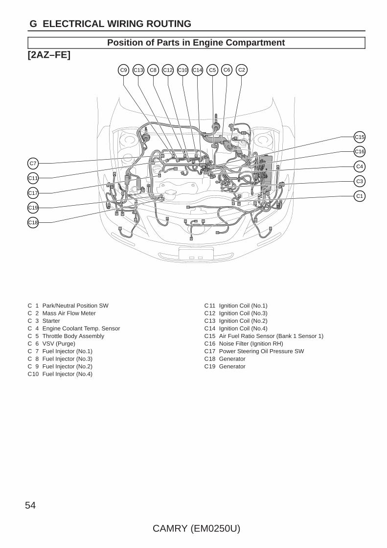
G ELECTRICAL WIRING ROUTING
Position of Parts in Engine Compartment[2AZ–FE]
C7
C11
C17
C18
C4
C3
C16
C15
C1
C9 C13 C8 C12 C10 C14 C6 C2C5
C19
C 1 Park/Neutral Position SWC 2 Mass Air Flow MeterC 3 StarterC 4 Engine Coolant Temp. SensorC 5 Throttle Body AssemblyC 6 VSV (Purge)C 7 Fuel Injector (No.1)C 8 Fuel Injector (No.3)C 9 Fuel Injector (No.2)C10 Fuel Injector (No.4)
C11 Ignition Coil (No.1)C12 Ignition Coil (No.3)C13 Ignition Coil (No.2)C14 Ignition Coil (No.4)C15 Air Fuel Ratio Sensor (Bank 1 Sensor 1)C16 Noise Filter (Ignition RH)C17 Power Steering Oil Pressure SWC18 GeneratorC19 Generator

CAMRY (EM0250U)
55
G
Position of Parts in Engine Compartment[2AZ–FE]
C26
C25
C27
C29
C28
C24
C32C20 C21 C22 C33 C23 D1C31C30
C20 Crankshaft Position SensorC21 A/C CompressorC22 Heated Oxygen Sensor (Bank 1 Sensor 2)C23 Engine Oil Pressure SWC24 Engine Control ModuleC25 Electronically Controlled Transmission SolenoidC26 Transmission Revolution Sensor (Turbine)C27 Transmission Revolution Sensor (Counter Gear)C28 Back–Up Lamp SWC29 StarterC30 Knock Control Sensor (Bank 1)C31 Camshaft Position SensorC32 Camshaft Timing Oil Control ValveC33 Intake Air Control Valve
D 1 Starter

56
CAMRY (EM0250U)
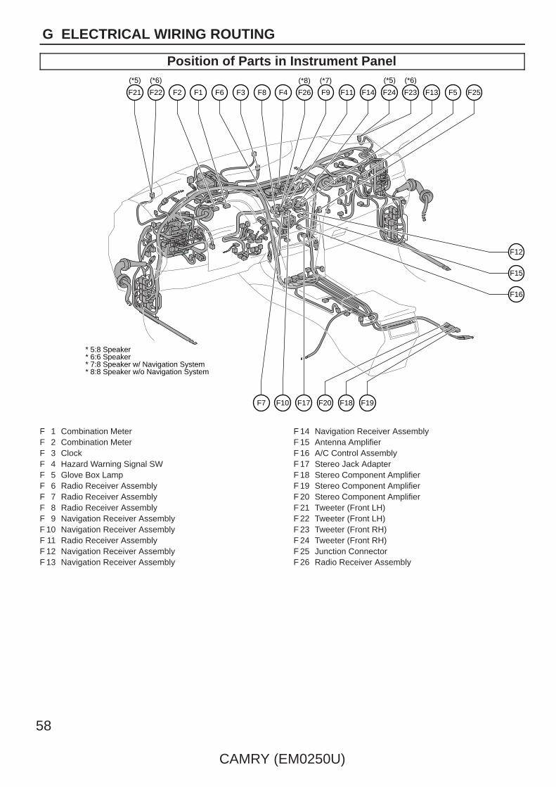
G ELECTRICAL WIRING ROUTING
Position of Parts in Instrument Panel
E8
E5
E9
E13
E3
E1E6E7 E15
(*1)
E12E14 E11 E24 E23 E25 E10
E20E18E16E17E21E2 E22E19
E27
E30 E32E29 E33 E31
(*1)
* 1:w/o Smart Key System
E 1 Diode (Door Courtesy Rear LH)E 2 Diode (Door Courtesy Rear RH)E 3 Outer Mirror SWE 5 Diode (Door Courtesy Front LH)E 6 Main Body ECUE 7 Main Body ECUE 8 Main Body ECUE 9 Main Body ECUE10 Data Link Connector 3E 11 Automatic Light Control SensorE12 Ion GeneratorE13 VSC Warning BuzzerE14 Turn Signal FlasherE15 Transponder Key ECUE16 Airbag Squib (Steering Wheel Pad)
E17 Steering SensorE18 Spiral CableE19 Windshield Wiper SW AssemblyE20 Windshield Wiper SW AssemblyE21 Headlamp Dimmer SW AssemblyE22 Unlock Warning SWE23 Ignition SWE24 Key Interlock SolenoidE25 Transponder Key AmplifierE27 A/C Room Temp. SensorE29 Power Outlet Socket (Front)E30 Airbag Sensor Assembly CenterE31 Transmission Control SWE32 Shift Lock Control ECUE33 Parking Brake SW

CAMRY (EM0250U)
57
G
Position of Parts in Instrument Panel
E40 E50
(*2)
E43
E42
E44 E45 E38 E37 E41
E49E48E54E51 E35E53
E61
E59
E39
E60
E52
E62E46 E63 E58
E55 E57E56 E65 E34
(*3)(*4)(*2)
* 2:w/ Smart Key System* 3:TMC Made* 4:TMMK Made
E34 Yaw Rate SensorE35 Power Outlet Socket (Rear)E37 Diode (Door Courtesy Front RH)E38 A/C AmplifierE39 Blower MotorE40 Junction ConnectorE41 Junction ConnectorE42 Junction ConnectorE43 Junction ConnectorE44 Junction ConnectorE45 Junction ConnectorE46 Junction ConnectorE48 Junction ConnectorE49 Junction ConnectorE50 ID Code Box
E51 Steering Lock ECUE52 Power SWE53 Tire Pressure Warning SW (Reset)E54 Airbag Squib (Knee Airbag)E55 Seat Heater SWE56 Electrical Key Oscillator (Console)E57 Shift Lock Control ECUE58 Certification ECUE59 Certification ECUE60 Tire Pressure Warning ECUE61 Option Connector (Bus Buffer)E62 Junction ConnectorE63 Junction ConnectorE65 Yaw Rate Sensor
58
CAMRY (EM0250U)
G ELECTRICAL WIRING ROUTING
Position of Parts in Instrument Panel
F15
F16
F12
F1F2F21 F22 F6 F9
(*7)
F26
(*8)
F8 F4F3 F11 F14 F13 F5
F7 F17F10
F25F24 F23
F20 F18 F19
(*5) (*6) (*5) (*6)
* 5:8 Speaker* 6:6 Speaker* 7:8 Speaker w/ Navigation System* 8:8 Speaker w/o Navigation System
F 1 Combination MeterF 2 Combination MeterF 3 ClockF 4 Hazard Warning Signal SWF 5 Glove Box LampF 6 Radio Receiver AssemblyF 7 Radio Receiver AssemblyF 8 Radio Receiver AssemblyF 9 Navigation Receiver AssemblyF 10 Navigation Receiver AssemblyF 11 Radio Receiver AssemblyF 12 Navigation Receiver AssemblyF 13 Navigation Receiver Assembly
F 14 Navigation Receiver AssemblyF 15 Antenna AmplifierF 16 A/C Control AssemblyF 17 Stereo Jack AdapterF 18 Stereo Component AmplifierF 19 Stereo Component AmplifierF 20 Stereo Component AmplifierF 21 Tweeter (Front LH)F 22 Tweeter (Front LH)F 23 Tweeter (Front RH)F 24 Tweeter (Front RH)F 25 Junction ConnectorF 26 Radio Receiver Assembly

CAMRY (EM0250U)
59
G
Position of Parts in Instrument Panel
A22
A58
A21
A18
N1A17A42A41A19 A56A57O1 e1 A40
c2c1b1a1
A17 Accelerator Position SensorA18 Parking Brake SWA19 Stop Lamp SWA21 Cruise Control Clutch SWA22 Clutch Start SWA40 Junction ConnectorA41 Junction ConnectorA42 Junction ConnectorA56 Short ConnectorA57 Short ConnectorA58 Junction Connector
N 1 Airbag Sensor Assembly Center
O 1 Airbag Sensor Assembly Center
a 1 Spiral CableSteering Pad SW
b 1 Cruise Control SWSpiral Cable
c 1 Airbag Squib (Front Passenger’s Airbag Assembly)c 2 Airbag Squib (Front Passenger’s Airbag Assembly)
e 1 A/C AmplifierA/C Blower Assembly

60
CAMRY (EM0250U)
G ELECTRICAL WIRING ROUTING
Position of Parts in Body
N34
N21
N6
N7
O12
P1
O17
O18
O8
O21
O10
O19
O13
N18 N29 O16 N19 O6 O7
N10N11N16N12N15N13N8 N23N28 O14 N17 N25 O15 N26 N24 O9
N 6 Door Courtesy SW (Driver’s Side)N 7 Side Airbag Sensor (Front LH)N 8 Pretensioner (LH)N10 Fuel Suction Pump and Gage AssemblyN11 Electrical Key Oscillator (Rear Seat)N12 Side Airbag Sensor (Rear LH)N13 Door Courtesy SW (Rear LH)N15 Noise Filter (Dome and Stop)N16 Center Stop LampN17 Canister Pump ModuleN18 Noise Filter (Rear Window Defogger)N19 Rear Window DefoggerN21 Curtain Shield Airbag Squib (LH)N23 Diode (Luggage Compartment Lamp)N24 Luggage Compartment LampN25 Electrical Key Oscillator (Inside Luggage Room)N26 Luggage Compartment LampN28 Junction ConnectorN29 Junction ConnectorN34 Tire Pressure Warning Antenna and Receiver
O 6 Door Courtesy SW (Front Passenger’s Side)O 7 Side Airbag Sensor (Front RH)O 8 Pretensioner (RH)O 9 Side Airbag Sensor (Rear RH)O10 Door Courtesy SW (Rear RH)O12 Speaker (Rear LH)O13 Speaker (Rear RH)O14 Speaker (Rear LH)O15 Speaker (Rear RH)O16 Curtain Shield Airbag Squib (RH)O17 Door Control ReceiverO18 Door Control ReceiverO19 Electrical Key AntennaO21 Junction Connector
P 1 Rear Window Defogger

CAMRY (EM0250U)
61
G
Position of Parts in Body
H6H5H4 Q11 Q10 W1 H8 H7 J1
I7I6 K3K1 K5 f1
Q3Q13Q6Q7 Q9 H2Q12 Q5 Q8 Q2
S11
S10
J5
J3
S4
S13
S12
S2
S1
S5S14S3 S8S6S16S15
S9
g1I1
I3
W2
H1
Q1
I5
I4
M1
X1
X2
(*2) (*1)
* 1:TMC Made* 2:TMMK Made* 3:w/ Smart Key System* 4:w/o Smart Key System
(*4) (*3)
H 1 Speaker (Front Door RH)H 2 Outer Rear View Mirror (RH)H 4 Power Window Regulator Motor
(Front Passenger’s Side)H 5 Door Lock Control SWH 6 Power Window SW (Front Passenger’s Side)H 7 Courtesy Lamp (Front Door RH)H 8 Door Lock Assembly (Front Passenger’s Side)
I 1 Speaker (Front Door LH)I 3 Outer Rear View Mirror (LH)I 4 Power Window Regulator Motor (Front LH)I 5 Power Window Regulator Motor (Front LH)I 6 Courtesy Lamp (Front Door LH)I 7 Door Lock Assembly (Driver’s Side)
J 1 Power Window SW (Rear RH)J 3 Power Window Regulator Motor (Rear RH)J 5 Door Lock Assembly (Rear RH)
K 1 Power Window SW (Rear LH)K 3 Power Window Regulator Motor (Rear LH)K 5 Door Lock Assembly (Rear LH)
M 1 Power Window Master SW
Q 1 Vanity Lamp SW (LH)Q 2 Vanity Lamp SW (RH)Q 3 Inner Rear View MirrorQ 5 Microphone (Navigation)Q 6 Overhead J/BQ 7 Vanity Lamp (LH)
Q 8 Vanity Lamp (RH)Q 9 Room Lamp (Center)Q10 Map Lamp (RH)Q11 Map Lamp (LH)Q12 Microphone (Navigation)Q13 Sliding Roof Control ECU and Motor
S 1 License Plate Lamp (RH)S 2 Rear Combination Lamp (RH)S 3 Rear Combination Lamp (LH)S 4 License Plate Lamp (LH)S 5 Door Lock Assembly (Luggage)S 6 Luggage Compartment Door Lock CylinderS 8 Luggage Compartment Door Lock CylinderS 9 Luggage Electrical Key SWS10 Turn Signal Lamp (Rear LH)S 11 Rear Combination Lamp (LH)S12 Rear Combination Lamp (RH)S13 Turn Signal Lamp (Rear RH)S14 Electrical Key Oscillator (Outside Luggage Room)S15 Junction ConnectorS16 Junction Connector
W 1 Door Outside Handle (Front RH)W 2 Electrical Key Oscillator (Front Door RH)
X 1 Door Outside Handle (Front LH)X 2 Electrical Key Oscillator (Front Door LH)
f 1 Speed Sensor (Rear LH)
g 1 Speed Sensor (Rear RH)
62
CAMRY (EM0250U)
G ELECTRICAL WIRING ROUTING
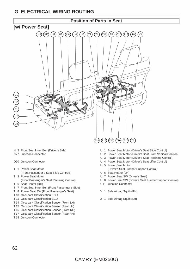
Position of Parts in Seat[w/ Power Seat]
T7 T1 T11 T6 T8
T15T14 T10 T16 T17 T3
T18U3N27U11 U6 U5U4
U7
U2
U1
U8
O20N3
Z1
Y1
N 3 Front Seat Inner Belt (Driver’s Side)N27 Junction Connector
O20 Junction Connector
T 1 Power Seat Motor (Front Passenger’s Seat Slide Control)
T 3 Power Seat Motor (Front Passenger’s Seat Reclining Control)
T 6 Seat Heater (RH)T 7 Front Seat Inner Belt (Front Passenger’s Side)T 8 Power Seat SW (Front Passenger’s Seat)T 10 Occupant Classification ECUT 11 Occupant Classification ECUT 14 Occupant Classification Sensor (Front LH)T 15 Occupant Classification Sensor (Rear LH)T 16 Occupant Classification Sensor (Front RH)T 17 Occupant Classification Sensor (Rear RH)T 18 Junction Connector
U 1 Power Seat Motor (Driver’s Seat Slide Control)U 2 Power Seat Motor (Driver’s Seat Front Vertical Control)U 3 Power Seat Motor (Driver’s Seat Reclining Control)U 4 Power Seat Motor (Driver’s Seat Lifter Control)U 5 Power Seat Motor
(Driver’s Seat Lumbar Support Control)U 6 Seat Heater (LH)U 7 Power Seat SW (Driver’s Seat)U 8 Power Seat SW (Driver’s Seat Lumbar Support Control)U11 Junction Connector
Y 1 Side Airbag Squib (RH)
Z 1 Side Airbag Squib (LH)
CAMRY (EM0250U)
63
G
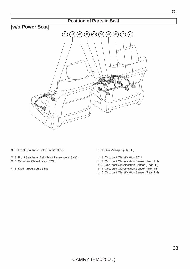
Position of Parts in Seat[w/o Power Seat]
d2 d3 O3 O4 d5d4N3Z1 d1 Y1
N 3 Front Seat Inner Belt (Driver’s Side)
O 3 Front Seat Inner Belt (Front Passenger’s Side)O 4 Occupant Classification ECU
Y 1 Side Airbag Squib (RH)
Z 1 Side Airbag Squib (LH)
d 1 Occupant Classification ECUd 2 Occupant Classification Sensor (Front LH)d 3 Occupant Classification Sensor (Rear LH)d 4 Occupant Classification Sensor (Front RH)d 5 Occupant Classification Sensor (Rear RH)
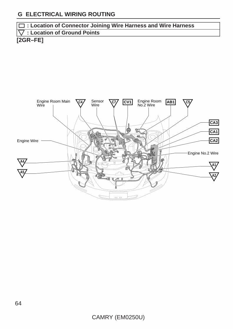
Engine Room MainWire
Engine RoomNo.2 Wire
SensorWire
Engine No.2 Wire
CV1 AB1 C5C4 C7
CA3
CA1
CA2
A1
A2A5
A4
Engine Wire
64
CAMRY (EM0250U)
G ELECTRICAL WIRING ROUTING
: Location of Connector Joining Wire Harness and Wire Harness: Location of Ground Points
[2GR–FE]

Engine Room MainWire
Engine Wire Engine RoomNo.2 Wire
AB1
CA3
CA1
CA2
A1
A2
A5
A4
C4C6
Engine No.2 Wire
CAMRY (EM0250U)
65
G
: Location of Connector Joining Wire Harness and Wire Harness: Location of Ground Points
[2AZ–FE]

66
CAMRY (EM0250U)
G ELECTRICAL WIRING ROUTING
: Location of Connector Joining Wire Harness and Wire Harness
Roof Wire AE7 AE2 FE3 FE2 AE4AE3
OA1Ec1EA1NA1
AE5
AE6
OF1
HE2
HE1
EO1
EO2
Front DoorRH Wire
FloorNo.2 Wire
EQ1
IE2
IE1
EN1
EN2
Engine Room Main Wire
Front DoorLH Wire
Instrument PanelWire
Instrument PanelWire Assembly
Floor Wire Instrument PanelNo.2 Wire
: Location of Ground Points
E1 E3F1
F2E2A3 F3A6

Front DoorRH Wire
Electrical Key Wire Harness RH
Roof Wire Rear DoorNo.1 Wire
FloorNo.3 Wire
FloorNo.2 Wire
Skid ControlSensor Wire
LuggageRoom Wire
Front DoorLH Wire
Floor WireRear DoorNo.2 Wire
HW1 JO1
SN1
gN1
O1
P1IM2
IM1
IX1
KN1
N1 S1
Electrical Key Wire Harness LH
Skid ControlSensor WirefO1
(*1)
(*2)
* 1:w/ Jam Protection* 2:w/o Jam Protection
CAMRY (EM0250U)
67
G
: Location of Connector Joining Wire Harness and Wire Harness: Location of Ground Points
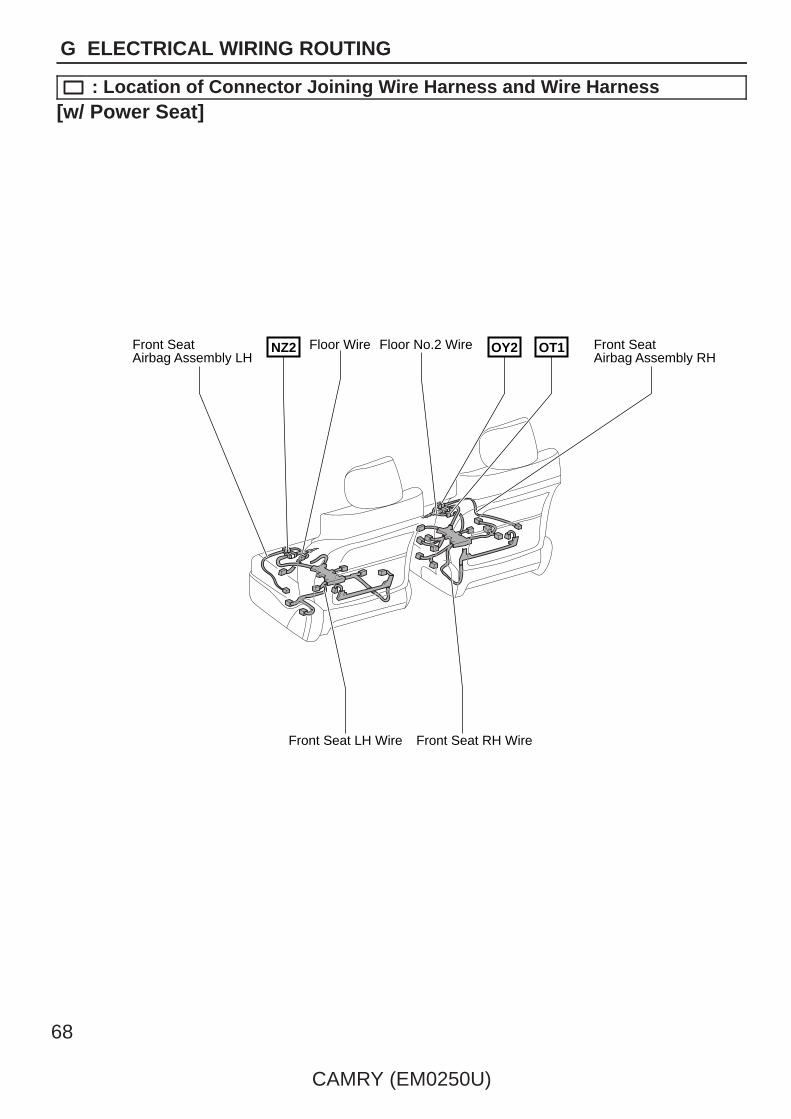
Floor No.2 WireFloor Wire Front SeatAirbag Assembly RH
Front SeatAirbag Assembly LH
OY2 OT1NZ2
Front Seat RH WireFront Seat LH Wire
68
CAMRY (EM0250U)
G ELECTRICAL WIRING ROUTING
: Location of Connector Joining Wire Harness and Wire Harness[w/ Power Seat]
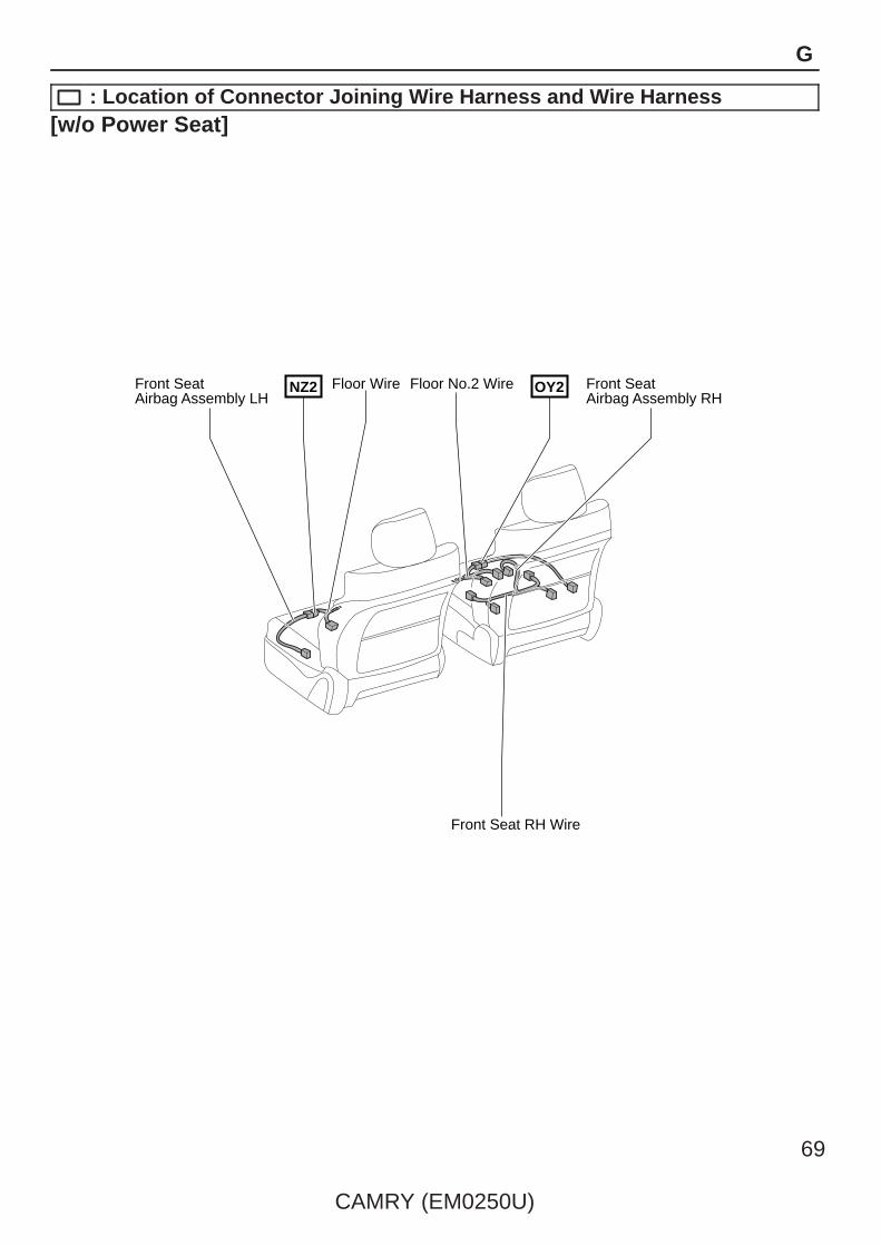
Floor No.2 WireFloor Wire Front SeatAirbag Assembly RH
Front SeatAirbag Assembly LH
OY2NZ2
Front Seat RH Wire
CAMRY (EM0250U)
69
G
: Location of Connector Joining Wire Harness and Wire Harness[w/o Power Seat]
70
CAMRY (EM0250U)
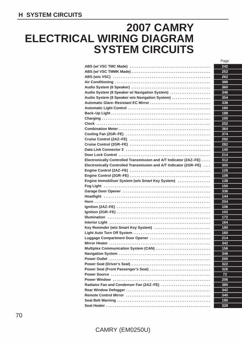
H SYSTEM CIRCUITS
2007 CAMRYELECTRICAL WIRING DIAGRAM
SYSTEM CIRCUITSPage
ABS (w/ VSC TMC Made) . . . . . . . . . . . . . . . . . . . . . . . . . . . . . . . . . . . . . . . . . . . . 242ABS (w/ VSC TMMK Made) . . . . . . . . . . . . . . . . . . . . . . . . . . . . . . . . . . . . . . . . . . . 252ABS (w/o VSC) . . . . . . . . . . . . . . . . . . . . . . . . . . . . . . . . . . . . . . . . . . . . . . . . . . . . . 262Air Conditioning . . . . . . . . . . . . . . . . . . . . . . . . . . . . . . . . . . . . . . . . . . . . . . . . . . . . 386Audio System (6 Speaker) . . . . . . . . . . . . . . . . . . . . . . . . . . . . . . . . . . . . . . . . . . . 360Audio System (8 Speaker w/ Navigation System) . . . . . . . . . . . . . . . . . . . . . . 346Audio System (8 Speaker w/o Navigation System) . . . . . . . . . . . . . . . . . . . . . 354Automatic Glare–Resistant EC Mirror . . . . . . . . . . . . . . . . . . . . . . . . . . . . . . . . . 338Automatic Light Control . . . . . . . . . . . . . . . . . . . . . . . . . . . . . . . . . . . . . . . . . . . . . 160Back–Up Light . . . . . . . . . . . . . . . . . . . . . . . . . . . . . . . . . . . . . . . . . . . . . . . . . . . . . . 188Charging . . . . . . . . . . . . . . . . . . . . . . . . . . . . . . . . . . . . . . . . . . . . . . . . . . . . . . . . . . . 100Clock . . . . . . . . . . . . . . . . . . . . . . . . . . . . . . . . . . . . . . . . . . . . . . . . . . . . . . . . . . . . . . 202Combination Meter . . . . . . . . . . . . . . . . . . . . . . . . . . . . . . . . . . . . . . . . . . . . . . . . . . 364Cooling Fan (2GR–FE) . . . . . . . . . . . . . . . . . . . . . . . . . . . . . . . . . . . . . . . . . . . . . . 374Cruise Control (2AZ–FE) . . . . . . . . . . . . . . . . . . . . . . . . . . . . . . . . . . . . . . . . . . . . 292Cruise Control (2GR–FE) . . . . . . . . . . . . . . . . . . . . . . . . . . . . . . . . . . . . . . . . . . . . 282Data Link Connector 3 . . . . . . . . . . . . . . . . . . . . . . . . . . . . . . . . . . . . . . . . . . . . . . 140Door Lock Control . . . . . . . . . . . . . . . . . . . . . . . . . . . . . . . . . . . . . . . . . . . . . . . . . . 214Electronically Controlled Transmission and A/T Indicator (2AZ–FE) . . . . . 312Electronically Controlled Transmission and A/T Indicator (2GR–FE) . . . . 300Engine Control (2AZ–FE) . . . . . . . . . . . . . . . . . . . . . . . . . . . . . . . . . . . . . . . . . . . . 126Engine Control (2GR–FE) . . . . . . . . . . . . . . . . . . . . . . . . . . . . . . . . . . . . . . . . . . . . 108Engine Immobiliser System (w/o Smart Key System) . . . . . . . . . . . . . . . . . . 138Fog Light . . . . . . . . . . . . . . . . . . . . . . . . . . . . . . . . . . . . . . . . . . . . . . . . . . . . . . . . . . 150Garage Door Opener . . . . . . . . . . . . . . . . . . . . . . . . . . . . . . . . . . . . . . . . . . . . . . . . 336Headlight . . . . . . . . . . . . . . . . . . . . . . . . . . . . . . . . . . . . . . . . . . . . . . . . . . . . . . . . . . 144Horn . . . . . . . . . . . . . . . . . . . . . . . . . . . . . . . . . . . . . . . . . . . . . . . . . . . . . . . . . . . . . . . 204Ignition (2AZ–FE) . . . . . . . . . . . . . . . . . . . . . . . . . . . . . . . . . . . . . . . . . . . . . . . . . . . 106Ignition (2GR–FE) . . . . . . . . . . . . . . . . . . . . . . . . . . . . . . . . . . . . . . . . . . . . . . . . . . . 102Illumination . . . . . . . . . . . . . . . . . . . . . . . . . . . . . . . . . . . . . . . . . . . . . . . . . . . . . . . . 172Interior Light . . . . . . . . . . . . . . . . . . . . . . . . . . . . . . . . . . . . . . . . . . . . . . . . . . . . . . . 164Key Reminder (w/o Smart Key System) . . . . . . . . . . . . . . . . . . . . . . . . . . . . . . . 190Light Auto Turn Off System . . . . . . . . . . . . . . . . . . . . . . . . . . . . . . . . . . . . . . . . . . 160Luggage Compartment Door Opener . . . . . . . . . . . . . . . . . . . . . . . . . . . . . . . . . 214Mirror Heater . . . . . . . . . . . . . . . . . . . . . . . . . . . . . . . . . . . . . . . . . . . . . . . . . . . . . . . 342Multiplex Communication System (CAN) . . . . . . . . . . . . . . . . . . . . . . . . . . . . . . 156Navigation System . . . . . . . . . . . . . . . . . . . . . . . . . . . . . . . . . . . . . . . . . . . . . . . . . . 346Power Outlet . . . . . . . . . . . . . . . . . . . . . . . . . . . . . . . . . . . . . . . . . . . . . . . . . . . . . . . 200Power Seat (Driver’s Seat) . . . . . . . . . . . . . . . . . . . . . . . . . . . . . . . . . . . . . . . . . . . 322Power Seat (Front Passenger’s Seat) . . . . . . . . . . . . . . . . . . . . . . . . . . . . . . . . . 326Power Source . . . . . . . . . . . . . . . . . . . . . . . . . . . . . . . . . . . . . . . . . . . . . . . . . . . . . . 72Power Window . . . . . . . . . . . . . . . . . . . . . . . . . . . . . . . . . . . . . . . . . . . . . . . . . . . . . 206Radiator Fan and Condenser Fan (2AZ–FE) . . . . . . . . . . . . . . . . . . . . . . . . . . . 380Rear Window Defogger . . . . . . . . . . . . . . . . . . . . . . . . . . . . . . . . . . . . . . . . . . . . . . 342Remote Control Mirror . . . . . . . . . . . . . . . . . . . . . . . . . . . . . . . . . . . . . . . . . . . . . . 340Seat Belt Warning . . . . . . . . . . . . . . . . . . . . . . . . . . . . . . . . . . . . . . . . . . . . . . . . . . . 190Seat Heater . . . . . . . . . . . . . . . . . . . . . . . . . . . . . . . . . . . . . . . . . . . . . . . . . . . . . . . . . 328

CAMRY (EM0250U)
71
H
Page
Shift Lock . . . . . . . . . . . . . . . . . . . . . . . . . . . . . . . . . . . . . . . . . . . . . . . . . . . . . . . . . . 320Sliding Roof . . . . . . . . . . . . . . . . . . . . . . . . . . . . . . . . . . . . . . . . . . . . . . . . . . . . . . . . 330Smart Key System . . . . . . . . . . . . . . . . . . . . . . . . . . . . . . . . . . . . . . . . . . . . . . . . . . 78
∗ Engine Immobiliser∗ Push Button Start System∗ Steering Lock∗ Wireless Door Lock Control
SRS . . . . . . . . . . . . . . . . . . . . . . . . . . . . . . . . . . . . . . . . . . . . . . . . . . . . . . . . . . . . . . . 273Starting (w/o Smart Key System) . . . . . . . . . . . . . . . . . . . . . . . . . . . . . . . . . . . . . 96Stop Light . . . . . . . . . . . . . . . . . . . . . . . . . . . . . . . . . . . . . . . . . . . . . . . . . . . . . . . . . . 186Taillight . . . . . . . . . . . . . . . . . . . . . . . . . . . . . . . . . . . . . . . . . . . . . . . . . . . . . . . . . . . . 172Theft Deterrent . . . . . . . . . . . . . . . . . . . . . . . . . . . . . . . . . . . . . . . . . . . . . . . . . . . . . 230Tire Pressure Warning System . . . . . . . . . . . . . . . . . . . . . . . . . . . . . . . . . . . . . . . 270TRAC (TMC Made) . . . . . . . . . . . . . . . . . . . . . . . . . . . . . . . . . . . . . . . . . . . . . . . . . . 242TRAC (TMMK Made) . . . . . . . . . . . . . . . . . . . . . . . . . . . . . . . . . . . . . . . . . . . . . . . . . 252Turn Signal and Hazard Warning Light . . . . . . . . . . . . . . . . . . . . . . . . . . . . . . . . 182VSC (TMC Made) . . . . . . . . . . . . . . . . . . . . . . . . . . . . . . . . . . . . . . . . . . . . . . . . . . . . 242VSC (TMMK Made) . . . . . . . . . . . . . . . . . . . . . . . . . . . . . . . . . . . . . . . . . . . . . . . . . . 252Wiper and Washer . . . . . . . . . . . . . . . . . . . . . . . . . . . . . . . . . . . . . . . . . . . . . . . . . . 196Wireless Door Lock Control (w/o Smart Key System) . . . . . . . . . . . . . . . . . . 224

72
CAMRY (EM0250U)
Power Source
1
(∗2)
(∗2)
B
L
W
B
B
Y
G
W
G
LG
O
L
R
LG
W
Y
B
(∗1)
W
DRL Relay
10A EFI NO. 1
10A MPX–B
30A EFI MAIN
21
15A H–LP (RH)
15A H–LP (LH)
1
1
1
7. 5A ALT–S
21
10A ETCS
21
15A HAZ
1 2
1
1
1
15A RADIO NO. 1
21
10A ECU–B NO. 1
21
10A DOME
21
120A ALT
1
1
1
1
1F1
1
1
1
11G
50A FAN MAIN
40A CDS FAN
40A RDI FAN
50A HTR
50A RR DEF
50A ABS No. 1
30A ABS No. 2
Battery
B
Y
FL MAIN3. 0W
Y
GeneratorC19(A), (C)
BR1
25A AMP
21
20A STR LOCK
11 2 B
1C1
(∗2)C1(∗1)A1
1 2SHORT

CAMRY (EM0250U)
73
10A HORN
H–LP (LL) Relay
HORN Relay
1E6
1E12 1 2
15A EFI NO. 2
10A EFI NO. 3
21
1 2
20A IG2
1 2
7. 5A AM2
(∗1)
30A ST/AM2
1 2
25A DOOR NO. 1
1
1
(∗3)
1(∗4)
1
1
(∗3)
1
1
W
G
5
1
3
2
4
1 1
H–LP (RL) Relay
1
S–HORN Relay
11
IB2 10A MIR HTR
A/F Relay
R
GR
Y
Y
B
B
RR DEF Relay
EFI Relay
B
∗ 4 : w/o Smart Key System∗ 3 : w/ Smart Key System∗ 2 : 2AZ–FE∗ 1 : 2GR–FE
15A H–LP (RL)
15A H–LP (LL)
7. 5A S–HORN
20A A/F
V G
W
W–B
Y
B
Y

74
CAMRY (EM0250U)
Power Source
(∗4)
4
5
2
1
6AM2
AM1
ACC
IG1
ST1
IG2
ST2
1AE7
EA17 12
4M124E
4G12
1
5
2
3
1
1
1
1(∗1)
104M
104EEA1
164G7
4E7
4G6
4E6Y
Y
B
L
LG LG
L
L
O
B B
(∗1 ∗3)
O
B
IG2 Relay
(∗4) (∗4)
(∗1 ∗3)
P(∗4)
W(∗4)
EA1
Y
18
O
(∗4)
B6
A1
(∗1 ∗3)
(∗3)
A11
(∗3)
(∗3)
(∗1 ∗3) (∗3)
B22
(∗3)
(∗3)
(∗3)
V
B3
BR
L
P
B17
W
(∗2)
B16
IG1D
ACCD
SSW1
SSW2
AM2
AM1
IG2D
(∗1)
Y
(∗1 ∗4)
BEA110
(∗1 ∗4)
Y
Y
( ∗1
∗4)
L
(∗1)
V
BR
BR
(∗3)
(∗3)(∗1)
(∗3)
B
O
W(∗4)
P(∗4)
Y
W
P
(∗3)
(∗3)
(∗2)
(∗4)
Main Body ECUE6(A), E7(B)
Ignition SWE23
(∗1)
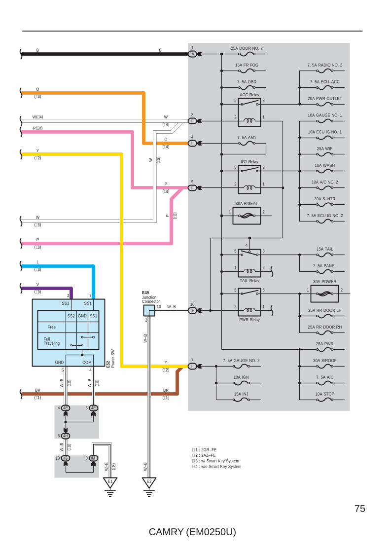
CAMRY (EM0250U)
75
7. 5A RADIO NO. 2
7. 5A ECU–ACC
20A PWR OUTLET
10A GAUGE NO. 1
10A ECU IG NO. 1
25A WIP
10A WASH
10A A/C NO. 2
20A S–HTR
7. 5A ECU IG NO. 2
15A TAIL
7. 5A PANEL
25A RR DOOR LH
25A RR DOOR RH
25A PWR
30A S/ROOF
7. 5A A/C
10A STOP
1
3
2
5
1 2
30A POWER
25A DOOR NO. 2
7. 5A AM1
5
2
3
1
1 2
30A P/SEAT
4
2
3
1
5
5
2
3
110IF
15A FR FOG
7. 5A OBD
IA1
II3
II4
II9
II7 7. 5A GAUGE NO. 2
10A IGN
15A INJ
E2
2
E1
5 4H
4 4E
IG10
4E5
B
W
O
P
W–B
Y
(∗2)
ACC Relay
TAIL Relay
PWR Relay
(∗4)
(∗4)
(∗4)
W
P
( ∗3)
( ∗3)
(∗1)
BR
W–B
W–B
W–B
W–B
W–B
W–B
( ∗3)
( ∗3)
( ∗3)
( ∗3)
10
5 4
2 7
IG1 Relay
V
L
(∗3)
(∗3)
B
O
W(∗4)
P(∗4)
Y
W
P
(∗3)
(∗3)
(∗2)
(∗4)
BR
(∗1)
∗ 4 : w/o Smart Key System∗ 3 : w/ Smart Key System∗ 2 : 2AZ–FE∗ 1 : 2GR–FE
JunctionConnector
E49
IM3
Free
FullTraveling
SS2 SS1
GND COM
Pow
er S
WE5
2
SS2 GND SS1
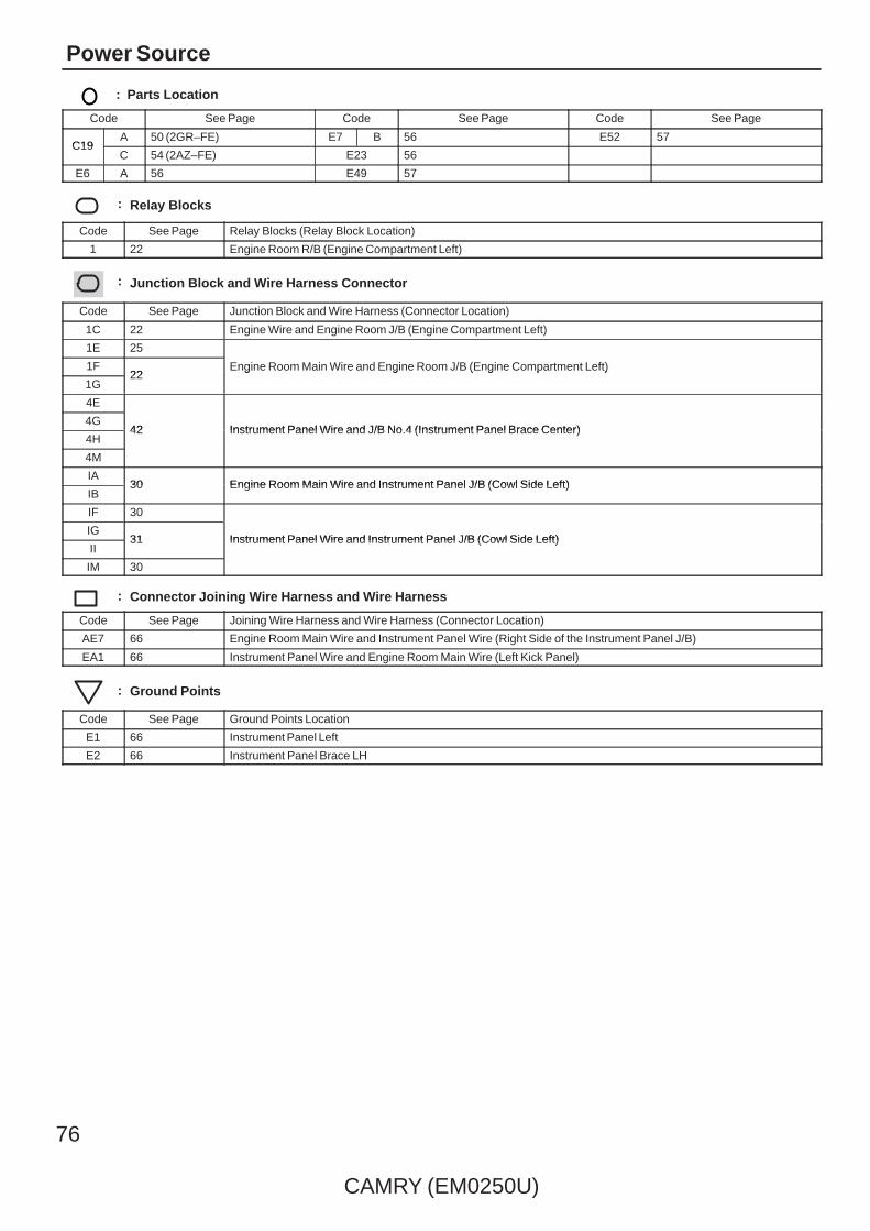
76
CAMRY (EM0250U)
Power Source
: Parts Location
Code See Page Code See Page Code See Page
C19A 50 (2GR–FE) E7 B 56 E52 57
C19C 54 (2AZ–FE) E23 56
E6 A 56 E49 57
: Relay Blocks
Code See Page Relay Blocks (Relay Block Location)
1 22 Engine Room R/B (Engine Compartment Left)
: Junction Block and Wire Harness Connector
Code See Page Junction Block and Wire Harness (Connector Location)
1C 22 Engine Wire and Engine Room J/B (Engine Compartment Left)
1E 25
Engine Room Main Wire and Engine Room J/B (Engine Compartment Left)1F22
Engine Room Main Wire and Engine Room J/B (Engine Compartment Left)
1G22
Engine Room Main Wire and Engine Room J/B (Engine Compartment Left)
4E
42 Instrument Panel Wire and J/B No.4 (Instrument Panel Brace Center)4G
42 Instrument Panel Wire and J/B No.4 (Instrument Panel Brace Center)4H
42 Instrument Panel Wire and J/B No.4 (Instrument Panel Brace Center)
4M
IA30 Engine Room Main Wire and Instrument Panel J/B (Cowl Side Left)
IB30 Engine Room Main Wire and Instrument Panel J/B (Cowl Side Left)
IF 30
Instrument Panel Wire and Instrument Panel J/B (Cowl Side Left)IG
31 Instrument Panel Wire and Instrument Panel J/B (Cowl Side Left)II
31 Instrument Panel Wire and Instrument Panel J/B (Cowl Side Left)
IM 30
: Connector Joining Wire Harness and Wire Harness
Code See Page Joining Wire Harness and Wire Harness (Connector Location)
AE7 66 Engine Room Main Wire and Instrument Panel Wire (Right Side of the Instrument Panel J/B)
EA1 66 Instrument Panel Wire and Engine Room Main Wire (Left Kick Panel)
: Ground Points
Code See Page Ground Points Location
E1 66 Instrument Panel Left
E2 66 Instrument Panel Brace LH

CAMRY (EM0250U)
77
Memo
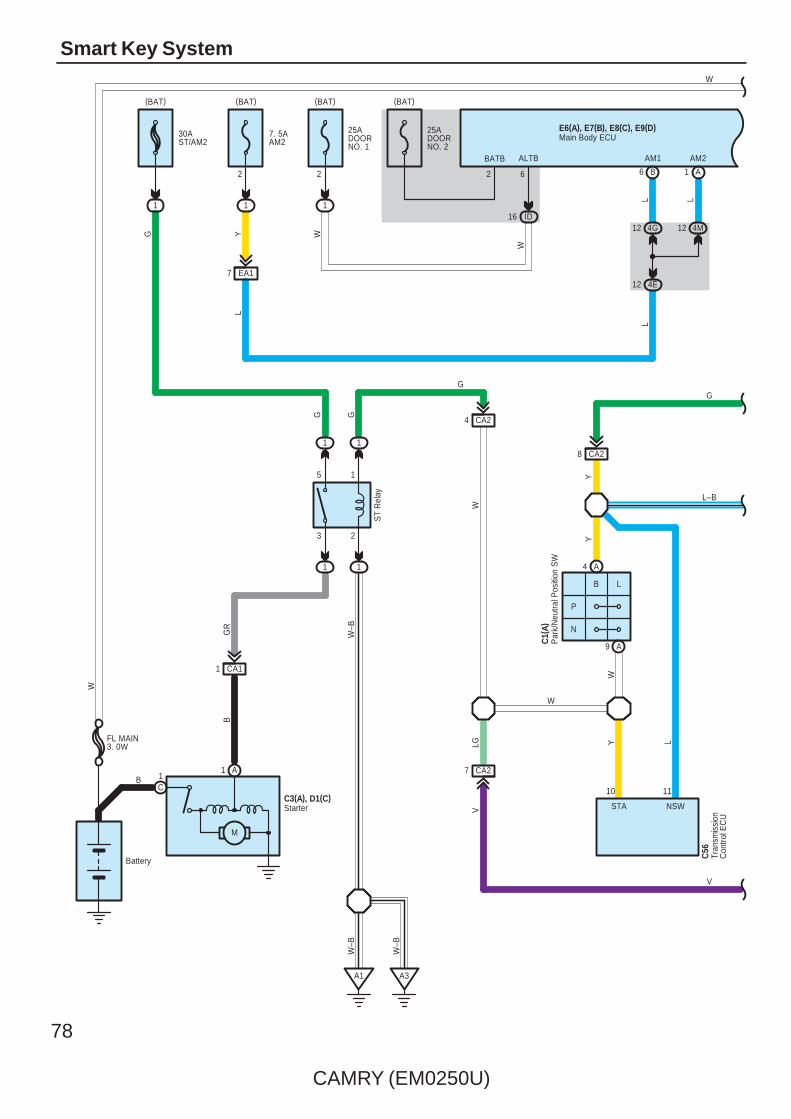
78
CAMRY (EM0250U)
Smart Key System
1
A6
L
25ADOORNO. 2
(BAT)
B
G
4 CA2
Y
Y
7. 5AAM2
1
8 CA2
(BAT)
BATB
2
W–B
12 4E
W–B
(BAT)
1
30AST/AM2
G
A3
3 2
5 1
1
ST
Rel
ay
1
1
Y
1
W
C1(
A)
CA11
A1
A1
LB
N
P
W–BGR
B
Battery
C1B
M
C3(A), D1(C)
G
12 4M12 4G
G
2
AM1
L L
AM2
EA17
WY
CA27
VLG
W
W
Par
k/N
eutra
l Pos
ition
SW
Starter STA NSW
10 11
Tran
smis
sion
Con
trol E
CU
C56
25ADOORNO. 1
2
1
(BAT)
ID16
W
ALTB
6
L
L
W
G
L–B
V
FL MAIN3. 0W
A4
A9
Main Body ECUE6(A), E7(B), E8(C), E9(D)
W

CAMRY (EM0250U)
79
BR
STR
5
ACCR
G
L
Y
OY
12 3F
12 3J
3 1
5 2
11
11
ST
CU
TR
elay
L
R
R
CA218
R
20AIG2
3 2
5 1
11
11
(BAT)
1
2
IG2Relay
BR
BR
A11
LG
IG2D
P
R
B
8 C
B
D4
STR2
A3
TACH
AE58AE515
GRV G
6 D
L–B
8 B
STSW
4G9
4F9
G
4K8
4E9
EA113
V
6A43
A2
EA118
10A
IGN
IG9
II7
BR
BR
AE54
Y
EA116
4M10
4E10
LG
AE613
G
4M4
4C5
4K7
4C9
P GR
Junction Connector
B63
A13 A14 A15
STAR
ACCR STSW TACH
RB R B
Eng
ine
Con
trol M
odul
eA5
5(A)
, C55
( B)
B
10 4C
9 4L
6 AE5
B
B62 A48
NSW STA
L–B V
L–B
V
Cra
nksh
aft
Pos
ition
Sen
sor
C5
C50
110
( Shi
elde
d)
RG
NE+
B
NE–
B
1
2
111
BR
Sto
p La
mp
SW
A19
A
STP
10ASTOP
IC8
(BAT)
W
A3
B8
B
A41(
A), A
42( B
)Ju
nctio
nC
onne
ctor
36L
STP
IL7
AE29
LW
23
Main Body ECUE6(A), E7(B), E8(C), E9(D)
W W
Y
1
2

80
CAMRY (EM0250U)
Smart Key System
A10 A11
IMO IMI
G Y
A49 A41
CANL CANH
W B
(∗3)C8(∗2)B8(∗1)A19
C19B29A5
C17B27A6
C7B7A20
C9B9A17
C10B10A3
C6B6A4
C5B5A18
Speed SensorsLG V P L R L B W
A1 A7
B4 B10
A2 A8
A11B35C26
A25B14C15
(∗1)A12(∗2)B33(∗3)C23
FL+ FL– FR+ FR– RL+ RL– RR+ RR–
CANH CANL SP1
AE66
BR
WC1C2
B1B2A1A2
BW
BWBW
B
W
WB
B W
B W
Junc
tion
Con
nect
orA4
0(A)
, E41
( B)
B
C5
CANH
W
C6
CANL
W B
Junc
tion
Con
nect
orE4
2(A)
, E43
( B) ,
E44(
C)
Ski
d C
ontro
l EC
U w
ith A
ctua
tor
A25(
C) ,
A26(
A), A
60( B
)
∗ 1 : w/ VSC TMC Made∗ 2 : w/ VSC TMMK Made∗ 3 : w/o VSC
W
Y
G
Eng
ine
Con
trol M
odul
eA5
5(A)
, C55
( B)
FE314 FE313
Main Body ECUE6(A), E7(B), E8(C), E9(D)
W W

CAMRY (EM0250U)
81
E2
B2IG+ B
10AMPX–B
1A
(BAT)
7. 5AGAUGENO. 2
IG12
(IG)
F1
W–B
VGR
SB
EA1
3D1
3Q12V
W–B
3Q7
3U2
A12A17 A18
10ADOME
1
2
(BAT)
R
LG
IF7
ID13
3L12
3Q1
R
3G2
3Q9
A13 A1 A2
GR
GR V
2
R
CANH CANL
A24
3Q5
3D10
A17
B18
CA34
C7
3
GR
W–B
GR
BR
A41(
A), A
42( B
)
ES
+B(DOME)
Mas
ter
War
ning
DRIVE ICMICRO COMPUTER
Power Supply Circuit
MULTI LCD
W–B
F1( A
) , F2
( B)
Buzzer
Junc
tion
Con
nect
or
Com
bina
tion
Met
er
JunctionConnector
C57
IG2
14 B
SI
3P11
3D3
WW
IG2
12 B
V
3P3
+S
3M10
V
C9
SPD
BR
BR
B W
W
B
EA115
3R8
W–B
W
Y
G
W–B
Y
G
3
Main Body ECUE6(A), E7(B), E8(C), E9(D)
W W
CANI/F

82
CAMRY (EM0250U)
Smart Key System
E49
W–B
3 4F
E2
1
2
W–B
E1
B
(IG)
14 IM
10AIGN
LG
21 AE2
B
2 4F
2 4D
3 4D
2 4A
W–B
W
1 4F
8 4A 4F78 4F
1 4M
E51
4F
W–B PO
11 4C
W–B
W
W
W
O
8 15
G
AE513
E50
G
7
IR9
LIN1
14
O
EFIIEFIOGND +B
6
LIN1
L
3
AE5
O
B
(BAT)
2
1
20ASTRLOCK
11
W–B
EA1
7
10
W–B
5216
BLINSGND
M
GNDIG2
3 4
SLP1IGE
PBR
SLPSLR+
18 B19 B
4F5
4C4
GL
1A2
(BAT)
W
3J1
3C1
W
4G10
4A10
4G5
4A5
PBR
O
P
Junc
tion
Con
nect
or
ID Code Box
SteeringLock ECU
Y
A8
B3
Junc
tion
Con
nect
orA4
1(A)
, A42
( B)
10AEFI NO. 1
W–B
Y
G
W
O
W–B
Main Body ECUE6(A), E7(B), E8(C), E9(D)
W W

CAMRY (EM0250U)
83
5 4H
W–B
SS2
GND
Free
FullTraveling
SS1 SS2
SS1
W–B
OLGP
SWILINDSINDW
4E54E4
GRG
45
COMGND
SWILINDSINDW
11121327
25 B
SSW2
15 B14 B
SSW1
16 B17 B
E1
W–B
W–B
4G4
4E3
3 IM
10 IG
4G11
4E11
4G8
4E8P LG O
RW
VC5CODETXCTAGND
4L5
GND3
1 C
W–B
W–B
E52Power SW
4G7
4E7
4G6
4E6
VL
V
L
W
O
W–B
W
O
W–B
R
W
GR
G
Main Body ECUE6(A), E7(B), E8(C), E9(D)
W W
8 9 10 14

84
CAMRY (EM0250U)
Smart Key System
3E11
3J10
3
CANL
2
1
W–B
W–B
4D3
ANT
O1
12 EO113 EO114
+B
W
2 AA1
Y
IND
4F4
R
2 AE2
2
1
24 B
WR
R
HSW
A2
R W
12 A11 A30 A 9 A 8 A 40 A
39 A38 A29 A21 A
A2728 A
17 A10 A
6
E
O
W–B
GND
LIN
2
1
6
W–B
AGNDTXCTCODE
1 3
CLGBCLG3
E56
AE2
BO
O
CLG5VC5
BZR
A3
5 2
GG
RC0
+5 DATA
3
Y
RSSI
5
R
RDA
Y
RSSI
CANH
R
CANP
16 C
CANN
15 C
CG5B
EO1EO1
ASEL
ASEL
VV
4
A37
11
E2
R W GR G
W–B
4F11
4K9
O
E58(
A), E
59( B
)
Electrical Key Oscillator(Console)
Cer
tific
atio
n E
CU
Junc
tion
Con
nect
orE4
9
GND1
Y
LP
8
19
3D5
3R11
Eng
ine
Hoo
dC
ourte
sy S
W
A5Ju
nctio
nC
onne
ctor
A43
SecurityIndicator
W L
W L
Clo
ckF3
Wire
less
Doo
r Lo
ck B
uzze
rA4
8
W
7
ANT
1
Ele
ctric
alK
ey A
nten
na
O19
Junc
tion
Con
nect
or
O21
Doo
r C
ontro
lR
ecei
ver
O18
W
O
W–B
G
GR
W
R
Main Body ECUE6(A), E7(B), E8(C), E9(D)
W W

CAMRY (EM0250U)
85
2 IX13
13 SN1
IX14 IX16 IX1
SN1
13 EN114 EN1 15 EN111 EN1
16 A15 A
R WWR
CG7BCLG7
N25
CLG6 CLGB
312
7 IX1
W–B
32 A31 A
34 A33 A22 A
14 A13 A
3 A
V P
EN116
PV
2
EN112
Y B
1
W
SGTANT1ANT2TRG–TRG–ANT2ANT1SGT
23891
1
R
G
BY
CG8BCLG8
GND
7
BR
RR
12 IE1
+B
1
YOV
V
6
SENS
14 IE1
SEL1
IE113
SEL
6 5 4
X2
TRG+
V
2
BB
SEN1
3 10
CLG
B
17
GR
IE1
GR
X1
TSW1
15 IE1
LGR
LG
CLG1
16 IE1
CLGB
5
A
CG6BCLG6
N11
CLG4 CLGB
3
P
1
5
LL
L
CG1B
V P
IX11 IX18
Electrical Key Oscillator(Rear Seat)
Electrical Key Oscillator(Inside Luggage Room)
CLG5 CLGB
Electrical Key Oscillator(Front Door LH)
W–B
RCertification ECUE58(A), E59(B)
Ele
ctric
alK
ey O
scilla
tor
( Out
side
Lug
gage
Roo
m)
S14
Door Outside Handle(Front LH)
Main Body ECUE6(A), E7(B), E8(C), E9(D)
W W
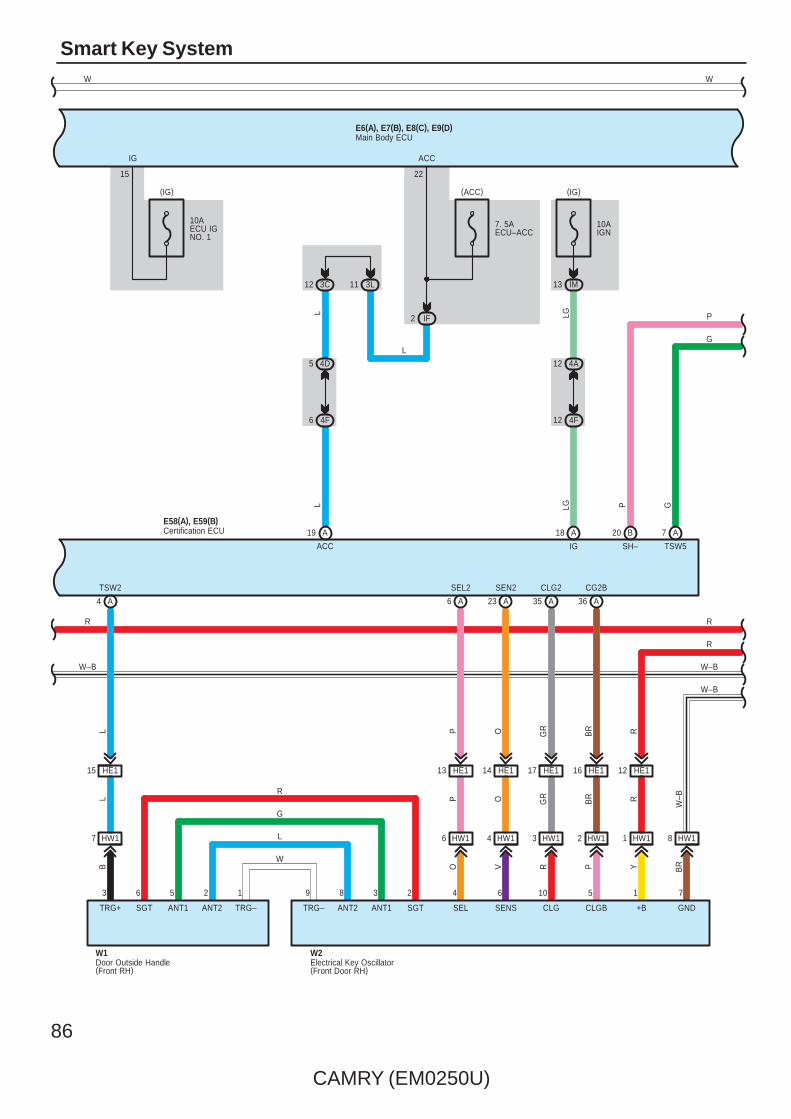
86
CAMRY (EM0250U)
Smart Key System
4 HW1
11 3L
2 IF
6 HW17 HW1
LG
13 IM
(IG)
10AIGN
HW13
7. 5AECU–ACC
HW12
W–B
20 B
P
SH–
4D5
4F6 12 4F
7 A19 A 18 A
36 A35 A23 A6 A4 A
L
(IG)
10AECU IGNO. 1
ACC IG
LGL
12 3C
IG
15
SGTANT1ANT2TRG–TRG–ANT2ANT1SGT
2389
G
TSW5
E58(A), E59(B)
R
G
L
W
4 10625
W2
GND
BR
HE117
YR
R
OP
P
HE113
SEL
OV
3
O
SEN2
HE1
SEL2
GR
RG
R
CLG2
16 HE1
CG2BB
RP
14
BR
HE1 12
6 1
W1
BL
L
TSW2
15 HE1
TRG+ SENS
1 75
+BCLGBCLG
4A12
22
ACC
(ACC)
8 HW11 HW1
L
Certification ECU
Door Outside Handle(Front RH)
Electrical Key Oscillator(Front Door RH)
R
W–B
R
R
W–B
W–B
P
G
Main Body ECUE6(A), E7(B), E8(C), E9(D)
W W

CAMRY (EM0250U)
87
S9
17 IE2
S15
2
ID
2
W–B
9
G
LG
12 3L
2 4E1 4E
RR
1 4A
R
12 3H
(BAT)
2
1
10ADOME
5 SN1SN114
17 EN1
17 HE2
W–B
W–B
W–B
12 AE6
P
W–B
13
2 C
TKUL
19 EN2
1
OG
OOG
W–B
E2 S1
IF7
R
3
2
13W
–B
W–B
1
5
W–B
Y
Junction Connector
Lugg
age
Ele
ctric
al K
ey S
W
JunctionConnector
E49
R
A2
TSW
RR
3F2
3N3
EN28
R
SN14
W–B
W–B
R
RLu
ggag
e C
ompa
rtmen
t Doo
rLo
ck C
ylin
der
S8
G
P
Y
Main Body ECUE6(A), E7(B), E8(C), E9(D)
W W
1

88
CAMRY (EM0250U)
Smart Key System
1A11 1D
LY
1A23
5
SecurityHorn
B
IE2
7
8
IE224 IE29
1
4
IK2
ACT+
1
RL
WW
GR
25
LSWP
27 A
ACTD
5 B9
LSWD
LL
W–B
LG
GR
Door Lock Assembly(Driver' s Side)
I7
IE217
W–B
LG
W–B
10 1D1B6
A411
A3
B B
GR
10A
HO
RN
Horn(High)
Horn(Low)
7. 5
A S
–HO
RN
HORN
ID11
25
B
HO
RN
Rel
ay
S–H
OR
N R
elay
Y
Main Body ECUE6(A), E7(B), E8(C), E9(D)
1G1
W
W W
W
M

CAMRY (EM0250U)
89
N1
25 HE2
IJ2
8
7
HE29
1
4
IJ1
9
6
KN13KN11
1
4
KN110
IP6 IP11
9
6
JO13JO11
1
4
JO110
IF18 IF5
EO18 EO14 EO116
KN14 JO14
LLG B L GR B L GR
LB GR
B LG W
LG L
2
W–B
W–B
ACT–
3
H8
K5 J5
W–B
W–B
HE1
LG
N29
5 3I
5 3O
O1
O218
W–B
7
G W GR
LG
GR
20
IP5
LSWL
3O
3D
A5
LSWR
V
LG
Doo
r Lo
ck A
ssem
bly
( Fro
nt P
asse
nger
's
Sid
e)
Doo
r Lo
ck A
ssem
bly
( Rea
r R
H)
Doo
r Lo
ck A
ssem
bly
( Rea
r LH
)
JunctionConnector
JunctionConnector
LGL
4
4
HE217
GR
W–B
Main Body ECUE6(A), E7(B), E8(C), E9(D)
W W
WW
W–B
W–B
W–B
M M M
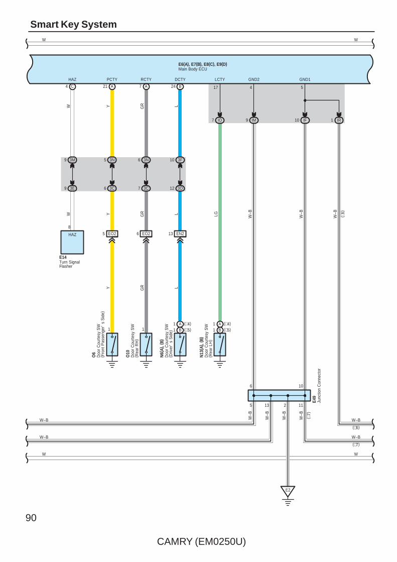
90
CAMRY (EM0250U)
Smart Key System
IM9
E2
2
GND2
4
W–B
W–B
Junc
tion
Con
nect
orE4
9
21
13
24
LCTY
17
EN2
N6(
A), (
B)
L
EO25
1
O6
Y
EO2
N13
( A) ,
( B)
6
1
O10
GR
3C7
3N6
L
DCTY
B
PCTY
A
RCTY
L
IO7
Y
LGGRY
7
3O12
3F10
3C6
GR
A
3N5
Doo
r C
ourte
sy S
W( R
ear
LH)
Doo
r C
ourte
sy S
W( D
river
's
Sid
e)
Doo
r C
ourte
sy S
W( R
ear
RH
)
Doo
r C
ourte
sy S
W( F
ront
Pas
seng
er'
s S
ide)
W–B
IF10
GND1
5
Main Body ECUE6(A), E7(B), E8(C), E9(D)
W W
WW
(∗5)B1(∗4)A1
(∗5)B1(∗4)A1
( ∗6)
1 IR
W–B
11
W–B
( ∗7)
W–B
W–B
(∗6)
(∗7)
W–B
W–B
5 13
6
W–B
W–B
10
9 3M
9 3E
WW
C
HAZ
4
Turn SignalFlasher
E14
8
HAZ
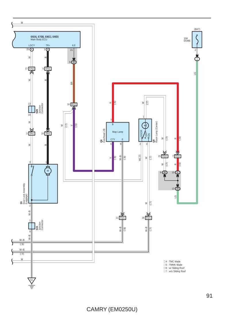
CAMRY (EM0250U)
91
W B
3 SN1
WW
A
W–B
S5
B
S1
B
B
TR+
5 EN1
1
2
M
EN217
3
W
LGCY
9
1
25 1
14
SN116
13
W–B
N28
S15
Junc
tion
Con
nect
orJu
nctio
nC
onne
ctor
Doo
r Lo
ck A
ssem
bly
( Lug
gage
)
LG
WR
( ∗6)V
( ∗7)
W( ∗
7)
B
( ∗6)
( ∗6)
( ∗6)
6
EQ116
IR5
BR
V
10ADOME
2
1
LG
(BAT)
ILE
21
W ( ∗6)
( ∗7)
CTY
7
2
ID13
EQ17
IL10R
R
1
WW
6 IR
15 EQ1
Q6 ( ∗
7)( ∗
7)
Ove
rhea
d J/
B
OFF
ON
DO
OR
∗ 4 : TMC Made∗ 5 : TMMK Made∗ 6 : w/ Sliding Roof∗ 7 : w/o Sliding Roof
Roo
m L
amp
( Cen
ter)
Q9
Main Body ECUE6(A), E7(B), E8(C), E9(D)
W
W
EQ118EQ111
8
E
W–B W( ∗6)
W ( ∗7)
W–B
( ∗7)
W–B
( ∗6)
W–B
W–B
(∗7)
(∗6)
Map Lamp
3
( ∗7)

92
CAMRY (EM0250U)
Smart Key System
∗ Steering lockReceiving signals from the power SW and the key, the certification ECU sends instruction for locking and unlocking thesteering lock to the steering lock ECU (Built in the steering lock) in order to activate the motor. The steering lock ECU detectsposition of the lock bar and stops the motor at the specified position.
: Parts Location
Code See Page Code See Page Code See Page
A3 48 (2GR–FE) E8 C 56 N11 60
A4 48 (2GR–FE) E9 D 56N13
A 60
A5 48 (2GR–FE) E14 56N13
B 60
A19 59 E41 B 57 N25 60
A23 48 (2GR–FE) E42 A 57 N28 60
A25 C 48 (2GR–FE) E43 B 57 N29 60
A26 A 48 (2GR–FE) E44 C 57 O6 60
A40 A 59 E49 57 O10 60
A41 A 59 E50 57 O18 60
A42 B 59 E51 57 O19 60
A43 49 (2GR–FE) E52 57 O21 60
A48 49 (2GR–FE) E56 57 Q6 61
A55 A 49 (2GR–FE) E58 A 57 Q9 61
A60 B 49 (2GR–FE) E59 B 57 S5 61
C1 A 50 (2GR–FE) F1 A 58 S8 61
C3 A 50 (2GR–FE) F2 B 58 S9 61
C50 51 (2GR–FE) F3 58 S14 61
C55 B 51 (2GR–FE) H8 61 S15 61
C56 51 (2GR–FE) I7 61 W1 61
C57 51 (2GR–FE) J5 61 W2 61
D1 C 51 (2GR–FE) K5 61 X1 61
E6 A 56N6
A 60 X2 61
E7 B 56N6
B 60
: Relay Blocks
Code See Page Relay Blocks (Relay Block Location)
1 22 Engine Room R/B (Engine Compartment Left)
System Outline

CAMRY (EM0250U)
93
: Junction Block and Wire Harness Connector
Code See Page Junction Block and Wire Harness (Connector Location)
1A
25Engine Room Main Wire and Engine Room J/B (Engine Compartment Left)
1B 25Engine Room Main Wire and Engine Room J/B (Engine Compartment Left)
1D
25Engine Room Main Wire and Engine Room J/B (Engine Compartment Left)
1G 22
3C
36 Instrument Panel Wire and J/B No.3 (Behind the Combination Meter)
3D
36 Instrument Panel Wire and J/B No.3 (Behind the Combination Meter)
3E
36 Instrument Panel Wire and J/B No.3 (Behind the Combination Meter)
3F
36 Instrument Panel Wire and J/B No.3 (Behind the Combination Meter)
3G
36 Instrument Panel Wire and J/B No.3 (Behind the Combination Meter)3H
36 Instrument Panel Wire and J/B No.3 (Behind the Combination Meter)3I
36 Instrument Panel Wire and J/B No.3 (Behind the Combination Meter)
3J
3L
3M
3N
3O
3P
36 Instrument Panel No.2 Wire and J/B No.3 (Behind the Combination Meter)3Q
36 Instrument Panel No.2 Wire and J/B No.3 (Behind the Combination Meter)3R
36 Instrument Panel No.2 Wire and J/B No.3 (Behind the Combination Meter)
3U
4A
42 Instrument Panel Wire and J/B No.4 (Instrument Panel Brace Center)
4C
42 Instrument Panel Wire and J/B No.4 (Instrument Panel Brace Center)
4D
42 Instrument Panel Wire and J/B No.4 (Instrument Panel Brace Center)
4E
42 Instrument Panel Wire and J/B No.4 (Instrument Panel Brace Center)4F
42 Instrument Panel Wire and J/B No.4 (Instrument Panel Brace Center)4G
42 Instrument Panel Wire and J/B No.4 (Instrument Panel Brace Center)
4H
4K
4L
4M
IC30 Engine Room Main Wire and Instrument Panel J/B (Cowl Side Left)
ID30 Engine Room Main Wire and Instrument Panel J/B (Cowl Side Left)
IF 30
Instrument Panel Wire and Instrument Panel J/B (Cowl Side Left)
IG31
Instrument Panel Wire and Instrument Panel J/B (Cowl Side Left)
II31
Instrument Panel Wire and Instrument Panel J/B (Cowl Side Left)IJ
30
Instrument Panel Wire and Instrument Panel J/B (Cowl Side Left)
IK30
Instrument Panel Wire and Instrument Panel J/B (Cowl Side Left)
IL30
IM
IO30 Floor Wire and Instrument Panel J/B (Cowl Side Left)
IP30 Floor Wire and Instrument Panel J/B (Cowl Side Left)
IR 30 Instrument Panel Wire and Instrument Panel J/B (Cowl Side Left)

94
CAMRY (EM0250U)
Smart Key System
: Connector Joining Wire Harness and Wire Harness
Code See Page Joining Wire Harness and Wire Harness (Connector Location)
AE2 66 Engine Room Main Wire and Instrument Panel Wire (Right Side of the Instrument Panel J/B)
AE566 Engine Room Main Wire and Instrument Panel Wire (Instrument Panel Right)
AE666 Engine Room Main Wire and Instrument Panel Wire (Instrument Panel Right)
CA1
64 (2GR–FE) Engine Wire and Engine Room Main Wire (Inside of the Engine Room R/B and Engine Room J/B)CA2 64 (2GR–FE) Engine Wire and Engine Room Main Wire (Inside of the Engine Room R/B and Engine Room J/B)
CA3
64 (2GR–FE) Engine Wire and Engine Room Main Wire (Inside of the Engine Room R/B and Engine Room J/B)
EA1 66 Instrument Panel Wire and Engine Room Main Wire (Left Kick Panel)
EN166 Instrument Panel Wire and Floor Wire (Left Kick Panel)
EN266 Instrument Panel Wire and Floor Wire (Left Kick Panel)
EO166 Instrument Panel Wire and Floor No.2 Wire (Right Kick Panel)
EO266 Instrument Panel Wire and Floor No.2 Wire (Right Kick Panel)
EQ1 66 Instrument Panel Wire and Roof Wire (Lower Part of Front Pillar LH)
FE3 66 Instrument Panel No.2 Wire and Instrument Panel Wire (Instrument Panel Center)
HE166 Front Door RH Wire and Instrument Panel Wire (Right Kick Panel)
HE266 Front Door RH Wire and Instrument Panel Wire (Right Kick Panel)
HW1 67 Front Door RH Wire and Electrical Key Wire Harness RH (Inside of the Front Door RH)
IE166 Front Door LH Wire and Instrument Panel Wire (Left Kick Panel)
IE266 Front Door LH Wire and Instrument Panel Wire (Left Kick Panel)
IX1 67 Front Door LH Wire and Electrical Key Wire Harness LH (Inside of the Front Door LH)
JO1 67 Rear Door No.1 Wire and Floor No.2 Wire (Right Center Pillar)
KN1 67 Rear Door No.2 Wire and Floor Wire (Left Center Pillar)
SN1 67 Luggage Room Wire and Floor Wire (Luggage Room Left)
: Ground Points
Code See Page Ground Points Location
A164 (2GR–FE) Front Left Fender
A264 (2GR–FE) Front Left Fender
A3 66 Left Cowl Side Panel
C5 64 (2GR–FE) Right Side of the Cylinder Block
C7 64 (2GR–FE) Left Side of the Cylinder Block
E1 66 Instrument Panel Left
E2 66 Instrument Panel Brace LH
F1 66 Instrument Panel Left
N1 67 Left Rear Quarter Panel
O1 67 Right Rear Quarter Panel
S1 67 Lower Back Panel Center

CAMRY (EM0250U)
95
Memo
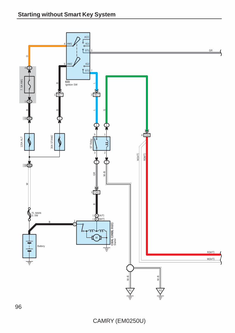
96
CAMRY (EM0250U)
Starting without Smart Key System
4 CA2
Battery
CA11
3 2
5 1
1 1
1 1
W–B
A1
B
C
B
4
5
3
7
AM2
AM1
ACC
IG1
ST1
IG2
ST2
G
B
1G1
1F
30A
ST/
AM
2
1
7. 5
A A
M1
IA1
II4
B B
W
120A
ALT
E23
AE71L
AE72L
W–B
B
ST
Rel
ay
O
11
W( A
/T)
W–B
A3
(A/T)A1(M/T)
R( M
/T)
1
GR
Ignition SW
R(M/T)
W(A/T)
GR
M
Sta
rter
C3(
A), C
29( B
) , D
1(C
)
FL MAIN3. 0W

CAMRY (EM0250U)
97
GR
L–B
18 CA2 CA2
P
N
BL
R
A A
B
8
PB
C1(
A), (
B)
SB
10
W
1 2
5 B (2AZ–FE)9 A (2GR–FE)
4 A (2GR–FE)4 B (2AZ–FE)
B11
( 2G
R–F
E)
CA39
53E
53F
A41(A), A42(B)
EA16
Y
Y
∗ 1 : 2AZ–FE A/T
VLG
( ∗1)
( ∗1)
( ∗1)
( A/T
)
( A/T
)
R
( M/T
)
G
( M/T
)
R(M/T)
P
( 2G
R–F
E)
W(A/T)
( 2A
Z–FE
)(2GR–FE)
L
(2GR–FE)( A
/T)
Y
R(M/T)
Junction Connector
Par
k/N
eutra
lP
ositi
on S
W
R(M/T)
W(A/T)
GR
10
11
NSW
STATr
ansm
issi
onC
ontro
l EC
U
C56STA
NSW
(2AZ–FE)D52(2GR–FE)B62
(2GR–FE)A48(2AZ–FE)C48
Eng
ine
Con
trol M
odul
e
A24(
C) ,
A55(
A),
C24
( D) ,
C55
( B)
R
( M/T
)
CA27
Clutch Start SWA22
2
1
W(A/T)
Y(2GR–FE)

98
CAMRY (EM0250U)
Starting without Smart Key System
: Parts Location
Code See Page Code See Page Code See Page
A22 59 C1 B 54 (2AZ–FE) C56 51 (2GR–FE)
A24 C 52 (2AZ–FE)C3 A
50 (2GR–FE)D1 C
51 (2GR–FE)
A41 A 59C3 A
54 (2AZ–FE)D1 C
55 (2AZ–FE)
A42 B 59 C24 D 55 (2AZ–FE) E23 56
A55 A 49 (2GR–FE) C29 B 55 (2AZ–FE)
C1 A 50 (2GR–FE) C55 B 51 (2GR–FE)
: Relay Blocks
Code See Page Relay Blocks (Relay Block Location)
1 22 Engine Room R/B (Engine Compartment Left)
: Junction Block and Wire Harness Connector
Code See Page Junction Block and Wire Harness (Connector Location)
1F22 Engine Room Main Wire and Engine Room J/B (Engine Compartment Left)
1G22 Engine Room Main Wire and Engine Room J/B (Engine Compartment Left)
3E36 Instrument Panel Wire and J/B No.3 (Behind the Combination Meter)
3F36 Instrument Panel Wire and J/B No.3 (Behind the Combination Meter)
IA 30 Engine Room Main Wire and Instrument Panel J/B (Cowl Side Left)
II 31 Instrument Panel Wire and Instrument Panel J/B (Cowl Side Left)
: Connector Joining Wire Harness and Wire Harness
Code See Page Joining Wire Harness and Wire Harness (Connector Location)
AE7 66 Engine Room Main Wire and Instrument Panel Wire (Right Side of the Instrument Panel J/B)
CA164 (2GR–FE)
Engine Wire and Engine Room Main Wire (Inside of the Engine Room R/B and Engine Room J/B)
CA165 (2AZ–FE)
Engine Wire and Engine Room Main Wire (Inside of the Engine Room R/B and Engine Room J/B)CA2
64 (2GR–FE) Engine Wire and Engine Room Main Wire (Inside of the Engine Room R/B and Engine Room J/B)CA2
65 (2AZ–FE)
Engine Wire and Engine Room Main Wire (Inside of the Engine Room R/B and Engine Room J/B)
CA3 65 (2AZ–FE)
EA1 66 Instrument Panel Wire and Engine Room Main Wire (Left Kick Panel)
: Ground Points
Code See Page Ground Points Location
A164 (2GR–FE)
Front Left FenderA165 (2AZ–FE)
Front Left Fender
A3 66 Left Cowl Side Panel

CAMRY (EM0250U)
99
Memo

100
CAMRY (EM0250U)
Charging
7. 5AALT–S
W
1
(BAT)
2
5 CA2G
–R
L
23 A
F1( A
)
R
Battery
(IG)
1G1 ( 2A
Z–FE
)
IH16
1C
W
120A
ALT
B
B
10AGAUGENO. 1
10 CA2
14 EA1
2 CA2
7. 5AGAUGENO. 2
12 IG
(IG)
3G2
3Q9
GR
GR
3 EA1
IG+
L
O
Y
13
LG
A
1 Cha
rge
CHG–
IG2
Com
bina
tion
Met
er
B2
B1 B4
Y
G–R
R
B IG
LS
C18
( B) ,
C19
( A) ,
( C)
IC Regulator
Gen
erat
or
B3
M
B50
ALT
Engine ControlModule
C24(B)
FL MAIN3. 0W
(2AZ–FE)C1(2GR–FE)A1
FE311

CAMRY (EM0250U)
101
: Parts Location
Code See Page Code See Page Code See Page
C18 B50 (2GR–FE)
C19A 50 (2GR–FE) C24 B 55 (2AZ–FE)
C18 B54 (2AZ–FE)
C19C 54 (2AZ–FE) F1 A 58
: Relay Blocks
Code See Page Relay Blocks (Relay Block Location)
1 22 Engine Room R/B (Engine Compartment Left)
: Junction Block and Wire Harness Connector
Code See Page Junction Block and Wire Harness (Connector Location)
1C 22 Engine Wire and Engine Room J/B (Engine Compartment Left)
1G 22 Engine Room Main Wire and Engine Room J/B (Engine Compartment Left)
3G 36 Instrument Panel Wire and J/B No.3 (Behind the Combination Meter)
3Q 36 Instrument Panel No.2 Wire and J/B No.3 (Behind the Combination Meter)
IG31 Instrument Panel Wire and Instrument Panel J/B (Cowl Side Left)
IH31 Instrument Panel Wire and Instrument Panel J/B (Cowl Side Left)
: Connector Joining Wire Harness and Wire Harness
Code See Page Joining Wire Harness and Wire Harness (Connector Location)
CA264 (2GR–FE)
Engine Wire and Engine Room Main Wire (Inside of the Engine Room R/B and Engine Room J/B)CA265 (2AZ–FE)
Engine Wire and Engine Room Main Wire (Inside of the Engine Room R/B and Engine Room J/B)
EA1 66 Instrument Panel Wire and Engine Room Main Wire (Left Kick Panel)
FE3 66 Instrument Panel No.2 Wire and Instrument Panel Wire (Instrument Panel Center)
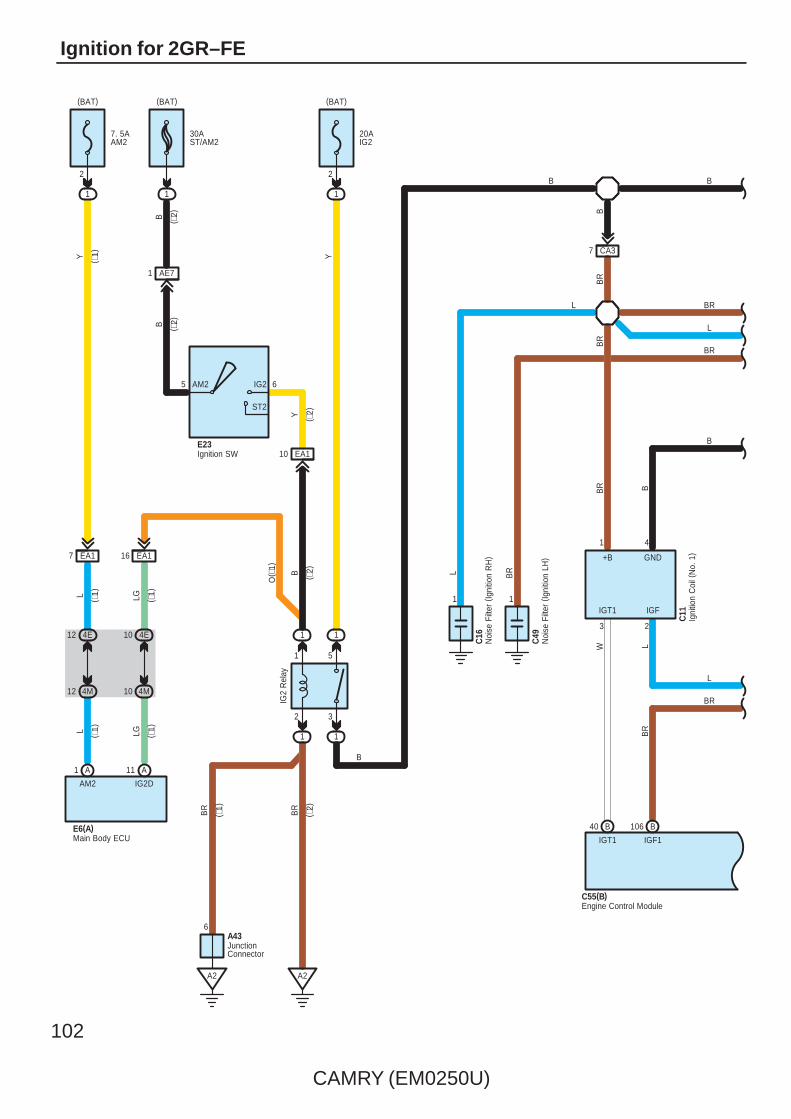
102
CAMRY (EM0250U)
Ignition for 2GR–FE
1
2
(BAT)
2
1 5
CA37
1 4
3
IGT1
GND+B
BR B
W
C11
1 1
1
1
A2
3
1
Y
B
L
IG2
Rel
ay
C16
1
BR
C49
IGF
2
L
BR
BR
BR
BR
E23
5
Y
6AM2 IG2
L
ST2
12 4M
12 4E
( ∗1)
L
A1
AM2
(BAT)( ∗
1)
1
7 EA1 16 EA1
A2
6
20AIG2
7. 5AAM2
(BAT)
30AST/AM2
1
EA110
4E10
4M10
B ( ∗2)
( ∗2)
O( ∗
1)
LG
B ( ∗2)
( ∗1)
Y ( ∗1)
LG ( ∗1)
A11
IG2D
2
E6(A)
BR
( ∗1)
BR
( ∗2)
A43
B
B
L
L
BR
B
JunctionConnector
Igni
tion
Coi
l (N
o. 1
)
Noi
se F
ilter
(Ig
nitio
n R
H)
Noi
se F
ilter
(Ig
nitio
n LH
)
Ignition SW
Main Body ECU
AE71
B ( ∗2)
B
L
BR
B40 B106
IGT1 IGF1
Engine Control ModuleC55(B)

CAMRY (EM0250U)
103
GND
IGT4
3
411 4
3
IGT2
GND+B
B–W B
G–R
1 4
3
IGT3
GND+B
L W
G LG
WBR
+B
C13
C12
C14
GND
IGT5
3
41
P
W–BBR
+BC
38GND
IGT6
3
41
L–B
W–BB
+B
C39
C7
IGF
2W
–L
IGF
2
W–L
IGF
2
R
IGF
2
R
IGF
2
L
W–B
B
CA32
W–L
W–LBR
L
W–B
W–B
B–W
B
W–B
Igni
tion
Coi
l (N
o. 3
)
Igni
tion
Coi
l (N
o. 2
)
Igni
tion
Coi
l (N
o. 4
)
Igni
tion
Coi
l (N
o. 5
)
Igni
tion
Coi
l (N
o. 6
)
BR
L
B
BR
L
BR
B
B39 B38 B37 B36 B35
IGT2 IGT3 IGT4 IGT5 IGT6
Engine Control ModuleC55(B)
∗ 2 : w/o Smart Key System∗ 1 : w/ Smart Key System
W
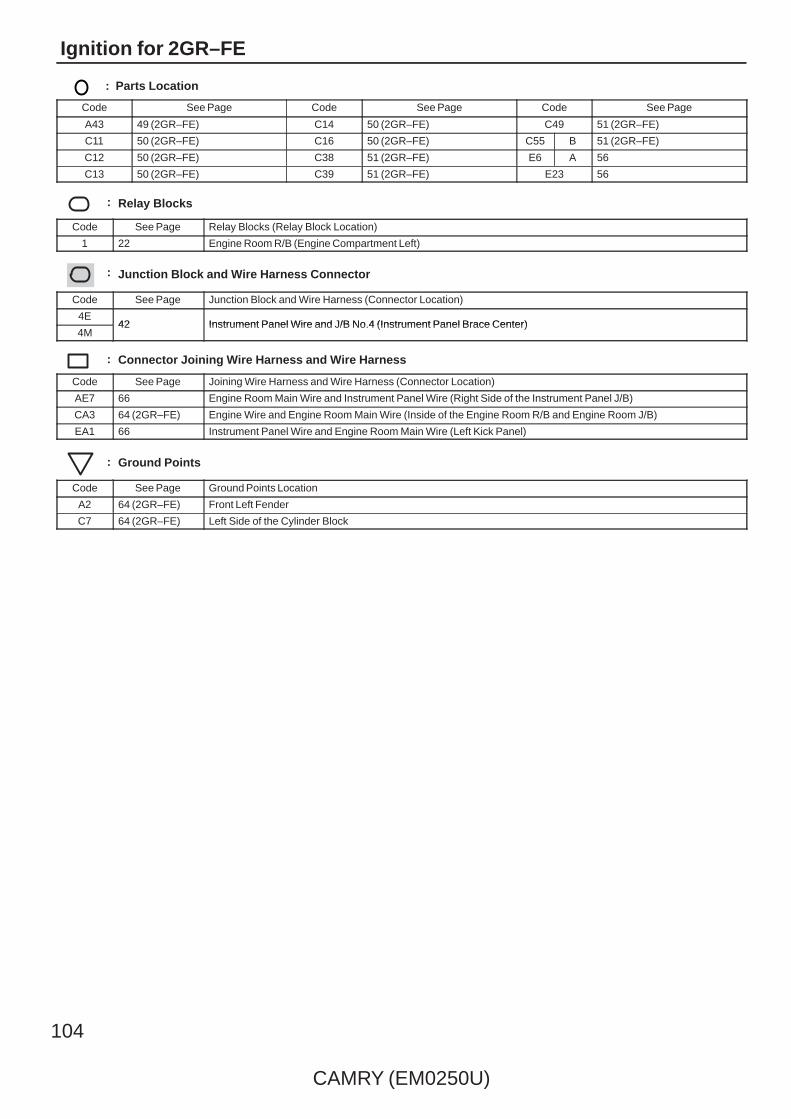
104
CAMRY (EM0250U)
Ignition for 2GR–FE
: Parts Location
Code See Page Code See Page Code See Page
A43 49 (2GR–FE) C14 50 (2GR–FE) C49 51 (2GR–FE)
C11 50 (2GR–FE) C16 50 (2GR–FE) C55 B 51 (2GR–FE)
C12 50 (2GR–FE) C38 51 (2GR–FE) E6 A 56
C13 50 (2GR–FE) C39 51 (2GR–FE) E23 56
: Relay Blocks
Code See Page Relay Blocks (Relay Block Location)
1 22 Engine Room R/B (Engine Compartment Left)
: Junction Block and Wire Harness Connector
Code See Page Junction Block and Wire Harness (Connector Location)
4E42 Instrument Panel Wire and J/B No.4 (Instrument Panel Brace Center)
4M42 Instrument Panel Wire and J/B No.4 (Instrument Panel Brace Center)
: Connector Joining Wire Harness and Wire Harness
Code See Page Joining Wire Harness and Wire Harness (Connector Location)
AE7 66 Engine Room Main Wire and Instrument Panel Wire (Right Side of the Instrument Panel J/B)
CA3 64 (2GR–FE) Engine Wire and Engine Room Main Wire (Inside of the Engine Room R/B and Engine Room J/B)
EA1 66 Instrument Panel Wire and Engine Room Main Wire (Left Kick Panel)
: Ground Points
Code See Page Ground Points Location
A2 64 (2GR–FE) Front Left Fender
C7 64 (2GR–FE) Left Side of the Cylinder Block

CAMRY (EM0250U)
105
Memo

106
CAMRY (EM0250U)
Ignition for 2AZ–FE
IH
(IG)
GND
IGT4
3
41
CA37
1 4
3
IGT1
GND+B
BR
W
1 4
3
IGT2
GND+B
BR
G–R
1 4
3
C11 IGT3
GND+B
BR
W–B
G LG
W–BBR
+B
1
C13
C12
C14
W–B
BB
BR
C16
C4
IGF
2
W–L
IGF
2
W–L
IGF
2
W–L
IGF
2
W–L
W–B
BR BRBR
W–L
BR
BR
W–L
BR
W–L
W–B
7
10 EA1Ig
nitio
n C
oil
( No.
1)
Igni
tion
Coi
l( N
o. 3
)
Igni
tion
Coi
l( N
o. 2
)
Igni
tion
Coi
l( N
o. 4
)
Noi
se F
ilter
(Ig
nitio
n R
H)
B85 B81 B84 B83 B82
Engine Control ModuleC24(B)
IGT1 IGF1 IGT2 IGT3 IGT4
W–B
W–B
W–B
15AINJ
W–B

CAMRY (EM0250U)
107
: Parts Location
Code See Page Code See Page Code See Page
C11 54 (2AZ–FE) C13 54 (2AZ–FE) C16 54 (2AZ–FE)
C12 54 (2AZ–FE) C14 54 (2AZ–FE) C24 B 55 (2AZ–FE)
: Junction Block and Wire Harness Connector
Code See Page Junction Block and Wire Harness (Connector Location)
IH 31 Instrument Panel Wire and Instrument Panel J/B (Cowl Side Left)
: Connector Joining Wire Harness and Wire Harness
Code See Page Joining Wire Harness and Wire Harness (Connector Location)
CA3 65 (2AZ–FE) Engine Wire and Engine Room Main Wire (Inside of the Engine Room R/B and Engine Room J/B)
EA1 66 Instrument Panel Wire and Engine Room Main Wire (Left Kick Panel)
: Ground Points
Code See Page Ground Points Location
C4 65 (2AZ–FE) Cylinder Block
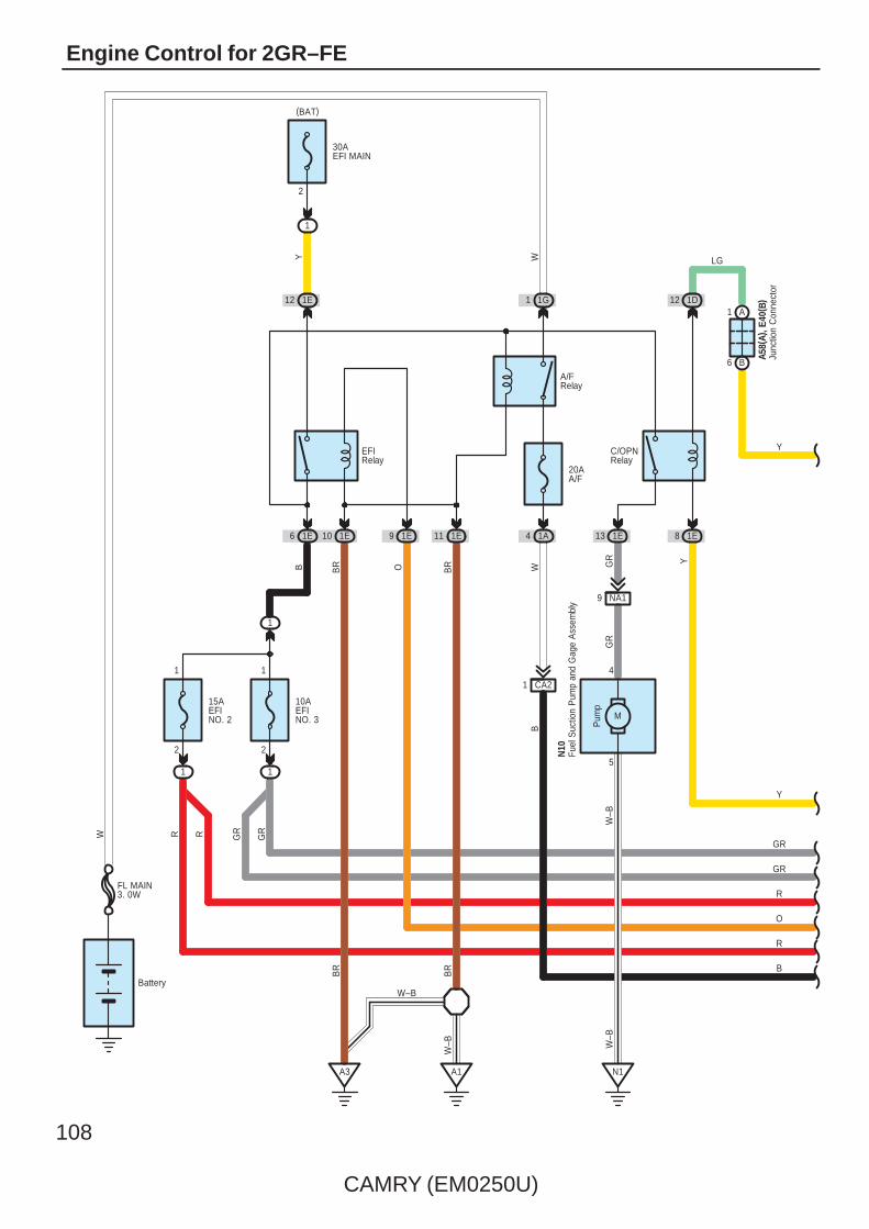
108
CAMRY (EM0250U)
Engine Control for 2GR–FE
A1
1E11
20AA/F
1
(BAT)
1E
Pum
p
1E 1E
A3
M
N1
5
4
1A
BR
N10
1E
2
1
6 10
1D
1E
B
2
W–B
GR
W–B
CA21
12
10AEFINO. 3
30AEFI MAIN
15AEFINO. 2
2
1
1
1
R
1
A1
B6
1E9
Battery
W
1G1
EFIRelay
W–B
BR
BR
BRO W
R GR
W
12
84B
13
LG
A58(
A), E
40( B
)
YGR
NA19W
–B
A/FRelay
C/OPNRelay
Y
Junc
tion
Con
nect
or
Fuel
Suc
tion
Pum
p an
d G
age
Ass
embl
y
B
R
O
R
GR
Y
FL MAIN3. 0W
Y
GR
GR
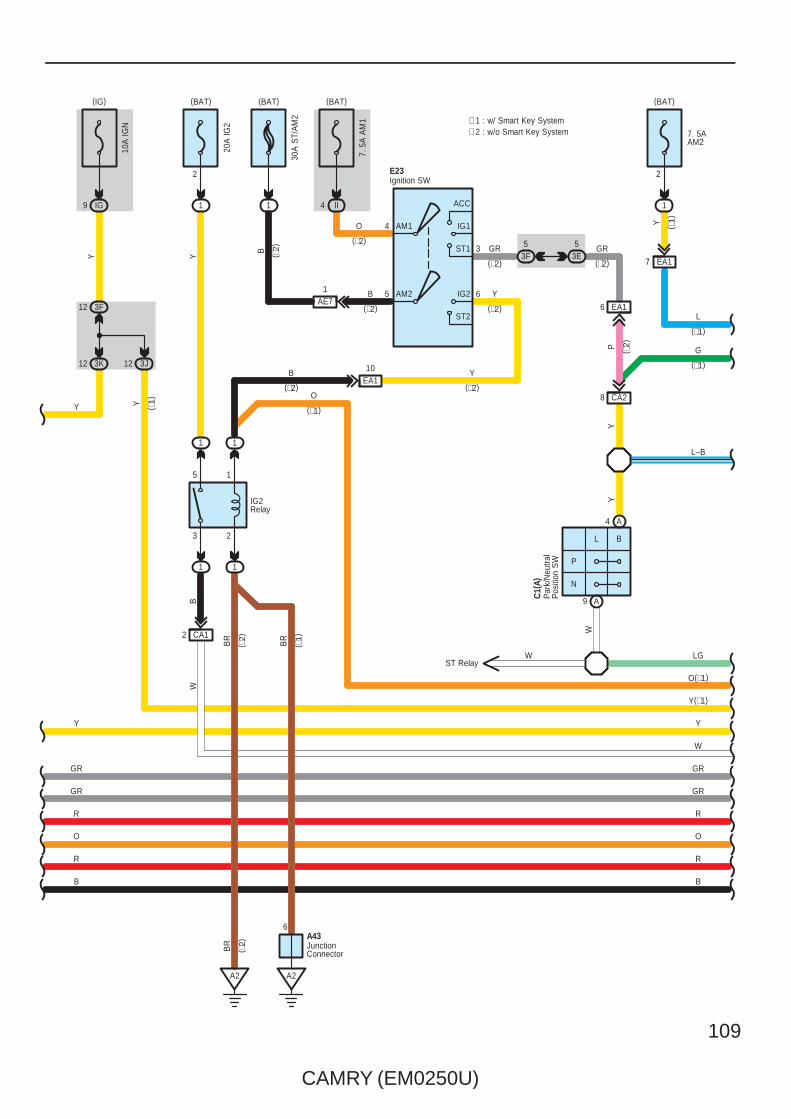
CAMRY (EM0250U)
109
(IG)
IG9
3 2
5 1
11
11
(BAT)
1
Y
2
A2
BR
B
CA12
W
20A
IG2
10A
IGN
3F12
3K12
A2
6
Y
IG2Relay
BR
( ∗2)
( ∗1)
A43
O(∗1)
Y
GR
BR
( ∗2)
30A
ST/
AM
2
1
(BAT)
EA110B
(∗2)
ST2
IG2AM2 65
E23
Y
B Y
(∗2)
(∗2)
1AE7
B ( ∗2)
(∗2)
JunctionConnector
Ignition SW
Y
O
R
GR
R
B
GR
CA2
P
N
BL
4
3
AM1
ACC
IG1
ST1
8
C1(
A)
W
9 A
4 A
53E
53F
EA16
YP
W
Y
Par
k/N
eutra
lP
ositi
on S
W
GR
7. 5
A A
M1
II4
O
LG
L–B
ST Relay
3J12
7 EA1
2
7. 5AAM2
Y
(BAT)
1
G
L
Y(∗1)
W
Y ( ∗1)
(BAT)
(∗2)
(∗2) (∗2)
( ∗2)
( ∗1)
(∗1)
∗ 1 : w/ Smart Key System∗ 2 : w/o Smart Key System
(∗1)
Y
GR
R
GR
R
B
O
(∗1)
O

110
CAMRY (EM0250U)
Engine Control for 2GR–FE
7CA2
VLG
L–B
JunctionConnector
GRP
9 4C
7 4K
5 4C
4 4M
G
13 AE6
LG
10 4E
10 4M
16 EA1Y
4 AE5
A2
A435
V
13 EA1
9 4E
8 4K
G
9 4F
9 4G
STSW
B8D6
GV GR
15 AE5 8 AE5
TACH
3 A
STR2
4 D
B
C8
R
P
IG2D
LG
11 A
R
R
L
ST
CU
TR
elay
1 1
1 1
25
13
O
Y
ACCRSTR
L
CA218
AM2LL
AM1
4G12 4M12
4E12
1B6 A
R(∗1)
B(∗1)
R(∗1)
L–B
V
Y
W
GRGR
Y
O(∗1)
G
L
Y(∗1)
W
Main Body ECUE6(A), E7(B), E8(C), E9(D)
B
(∗1)
(∗1)
( ∗1)
( ∗1)
( ∗1)
( ∗1)
( ∗1)
( ∗1) ( ∗
1)
( ∗1)
( ∗1)
( ∗1)
( ∗1)
(∗1)
( ∗1)
( ∗1)
( ∗1)
( ∗1)
( ∗1)
(∗1)
( ∗1)
( ∗1)
( ∗1)
( ∗1)
R(∗1)
∗ 1 : w/ Smart Key System
CANH
6 C 5 C
CANL
B
W
O
R
GR
R
B
O
R
R
GR
B
( ∗1)
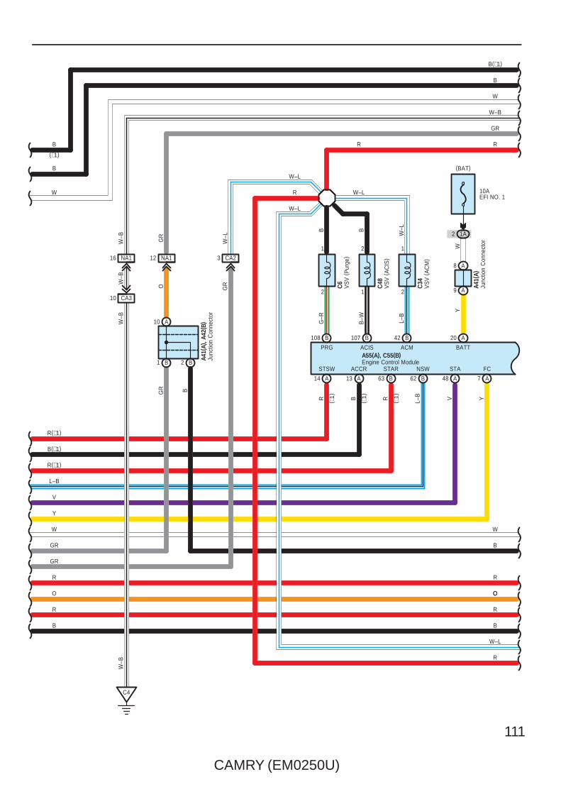
CAMRY (EM0250U)
111
A
FC
PRG
B
2
1
BG
–R
Y
C6
108
7
ACIS
B
1
2
B–W
C48
107
BB1 B2
A10
A41(
A)
A9
A8
10AEFI NO. 1
1A2
(BAT)
NA112NA116
CA310
C4
CA23
2
1
GR B
W–B GR
O GRW
–BW
–B
Y
W
GR
WY
W–B
W–L
R
W–L
W–L
W–L
W–L
R
L–B
C34
ACM
B42
Junc
tion
Con
nect
or
VS
V (
AC
M)
VS
V (
AC
IS)
VS
V (
Pur
ge)
L–B
62
NSW
B 48
V
STA
A
B
13
ACCR
A 63R
STAR
BA
STSW
R
14
A20
BATT
L–B
R(∗1)
B(∗1)
R(∗1)
B R
GR
W–B
W
B
R
O
Engine Control ModuleA55(A), C55(B)
(∗1)
( ∗1)
( ∗1)
( ∗1)
B(∗1)
B
W
B
W
V
R
R
O
GR
B
R
B
O
W–L
R
Junc
tion
Con
nect
orA4
1(A)
, A42
( B)
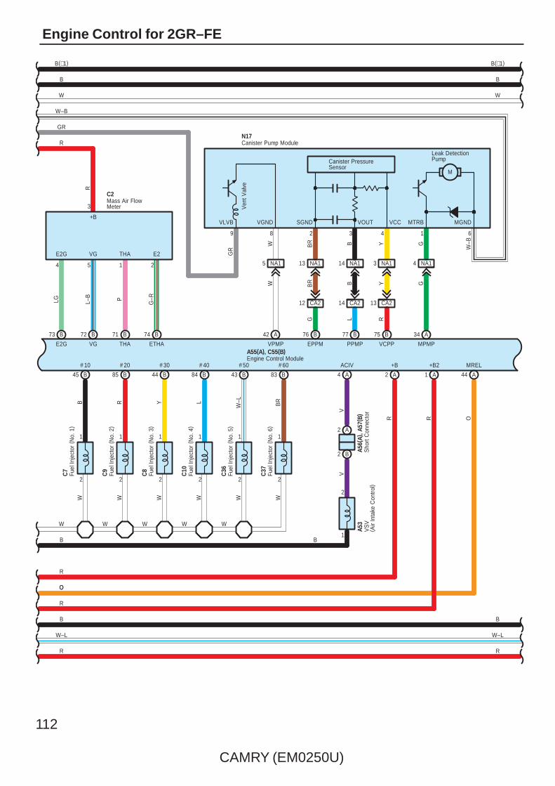
112
CAMRY (EM0250U)
Engine Control for 2GR–FE
E2G
B
4
LG
VG
B
5
L–B
THA
B
1
P
3
+B
E2G VG THA
R
717273
ETHA
B
2
G–R
E2
74
C2
2
1
C7
W
B
# 10
B
45
2
1
C9
W
B
# 20
R
85
2
1
C8
W
B
# 30
Y
44
2
1
C10
W
B
# 40
L
84
2
1
C36
W
B
# 50
W–L
43
2
1
C37
W
B
# 60
BR
83
W W W W
NA114 NA13NA113NA15 NA14
CA214 CA21312 CA2
MREL
44 A
O
GW BR YB
B YBRW G
RR
+B2
1 A
+B
2 A
N17
8 2 43
G RL
77 B
MPMP
75
VPMP
B
EPPM VCPPPPMP
76
ACIV
4 A
B
1
2
42 A
A2
B2
V34
VA
A56(
A), A
57( B
)
B
A53
B
R
W–L
A55(A), C55(B)
W
SGND
Leak DetectionPump
M
Canister PressureSensor
Ven
t Val
ve
GR
VOUT VCC
9
VLVB
6
W–B
VGND MGNDMTRB
VS
V( A
ir In
take
Con
trol)
Engine Control ModuleS
hort
Con
nect
or
Fuel
Inje
ctor
(N
o. 4
)
Mass Air FlowMeter
Fuel
Inje
ctor
(N
o. 5
)
Fuel
Inje
ctor
(N
o. 6
)
Fuel
Inje
ctor
(N
o. 1
)
Fuel
Inje
ctor
(N
o. 3
)
Fuel
Inje
ctor
(N
o. 2
)
Canister Pump Module
W–B
GR
R
B
R
O
W
B
B(∗1)B(∗1)
B
W
O
R
B
W–L
R
1

CAMRY (EM0250U)
113
+BM
A
1
LG
(BAT)
3
2
1
BR
ID
Y
A
IGSW
111
2
1
B
NE–
B
NE+
( Shi
elde
d)
G R
( Shi
elde
d)
B
OX2B
B
EX2B
B
HT2B
OX2B E2 HT2B
3 4 1
OX1B E2HT1B
W–L
B
W–B Y
413
B
EX1B
B
HT1B
B
OX1B
BR
LGW
2
+B
C52
( Shi
elde
d)
( Shi
elde
d)
C51
10AIGN
IG9
110 88 48 65476487
ST1–
B
A
2
GR
A19
(IG)
2835
R
+B
R
( Shi
elde
d)
W–L
C50
C5
10AETCS
3F12
3K12
A2
B6
YY
YB
A58(
A), E
40( B
)
A55(A), C55(B)
Sto
p La
mp
SW
Engine Control Module
Junc
tion
Con
nect
or
Cra
nksh
aft
Pos
ition
Sen
sor
Heated Oxygen Sensor(Bank 2 Sensor 2)
Heated Oxygen Sensor(Bank 1 Sensor 2)
B
10ASTOP
IC8
(BAT)
A3
B8
B
A41(
A), A
42( B
)Ju
nctio
n C
onne
ctor
36
W
A
STP
∗ 1 : w/ Smart Key System
B
B(∗1)
WW
B
B(∗1)
L
L
1 4
2 3
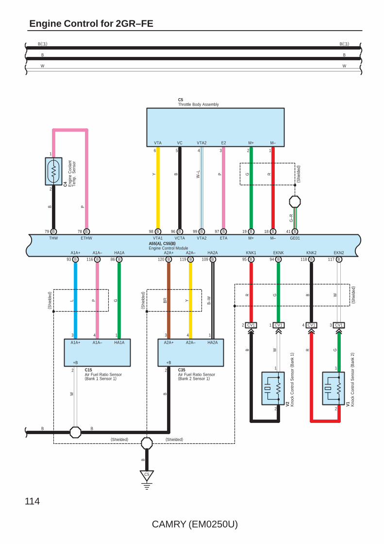
114
CAMRY (EM0250U)
Engine Control for 2GR–FE
1
79
B
ETHW
B
THW
B
P
78
3 CV1
( Shi
elde
d)
5
M+
B
G
M–
B
R
GE01
B
VCTA
B
A1A+
B
A1A–
B
HA1A
A1A+ A1A– HA1A
3 4 1
L P G
B
A2A+
B
A2A–
B
HA2A
A2A+ A2A– HA2A
3 4 1
BR Y
B–W
2 2
+B +B
120 119 109
( Shi
elde
d)
( Shi
elde
d)
W B
2
1
B
EKN2
B
KNK2
CV14
1
2
B
EKNK
B
KNK1
CV11CV12
V2 V1
R G B WGRWB
( Shi
elde
d)
411819
8611693 1171189495
C5
B 97
P
B
ETA
99
W–L
B
VTA2
34 2 1
M–M+E2VTA2VCVTA
98
Y
B
VTA1
B
96
6
(Shielded)(Shielded)
2
G–R
C15 C35
B
B
C5
Air Fuel Ratio Sensor(Bank 1 Sensor 1)
Air Fuel Ratio Sensor(Bank 2 Sensor 1)
Throttle Body Assembly
Kno
ck C
ontro
l Sen
sor
( Ban
k 2)
Kno
ck C
ontro
l Sen
sor
( Ban
k 1)
Eng
ine
Coo
lant
Tem
p.
Sen
sor
C4
B
Engine Control ModuleA55(A), C55(B)
B
W
B(∗1)
W
B
B(∗1)
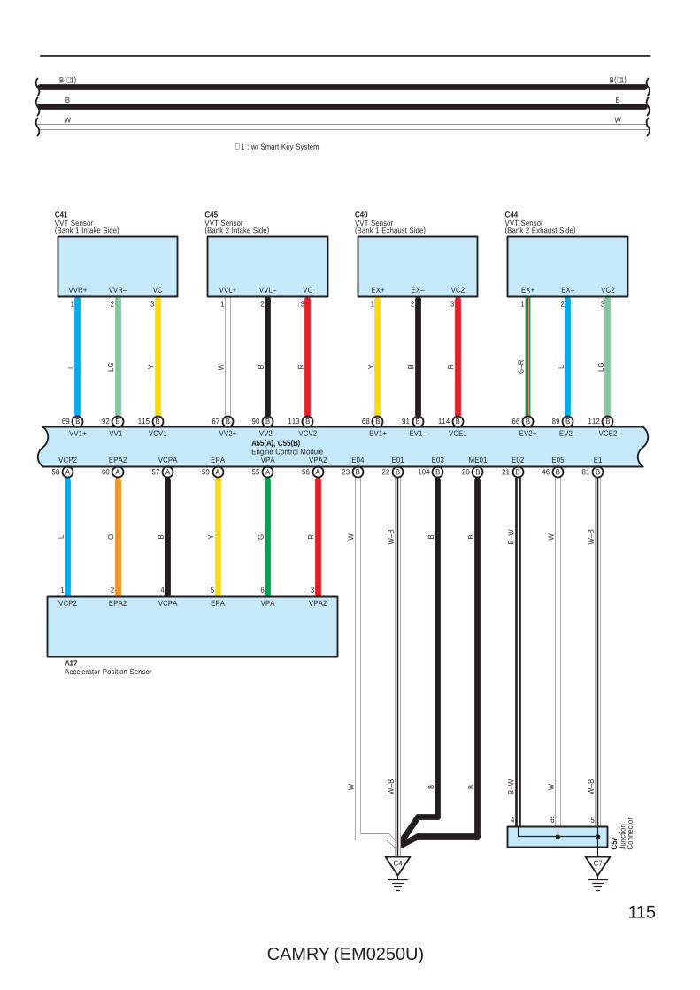
CAMRY (EM0250U)
115
W–BB
20 46 8121B
ME01
B
E05
B
E1B W
C44C40C45C41
32132131 2321
LGL
G–RRBYRW B
VVR+ VVR– VC VVL–VVL+ VC EX+ EX– VC2 EX+ EX– VC2
VCE2EV2–EV2+VCE1EV1–EV1+VCV2VV2+ VV2–VCV1VV1–VV1+
112 B89 B66
C7
B114 B91 B68 B113 B67 B 90 B115 B92 B69 B
A17
3
VPA2
6
VPA
5
EPA
4
VCPA
2
EPA2
1
VCP2
RGYBOL
VCP2 EPA2 VCPA EPA VPA VPA2
58 60 57 59 55 56 AAAAAA
B–W
E02
B23 22 104B
E04
B
E01
B
E03
W W–B
C4
6 54
W–BB B WB
–WW W–B
Accelerator Position Sensor
VVT Sensor(Bank 1 Exhaust Side)
VVT Sensor(Bank 1 Intake Side)
VVT Sensor(Bank 2 Exhaust Side)
VVT Sensor(Bank 2 Intake Side)
Junc
tion
Con
nect
or
C57
Engine Control ModuleA55(A), C55(B)
∗ 1 : w/ Smart Key System
B
W
B(∗1)
W
B(∗1)
B
L LG Y

116
CAMRY (EM0250U)
Engine Control for 2GR–FE
OE1+
B
OE1–
B
2
1
OE2+
B
OE2–
B
2
1
OC2+
B
OC2–
B
OC1+
B
OC1–
B
1
22
1
C46
C42
C47
C43
W–L YL LG BR RW B
5152575815141716
IGF1
B
IGT1
B
IGT2
B
IGT3
B
IGT4
B
IGT5
B
IGT6
B
BR W G–R G LG P L–B
353637383940106 70
PSW
B
1B
Cam
shaf
t Tim
ing
Oil
Con
trol V
alve
( RH
Exh
aust
Sid
e)
Cam
shaf
t Tim
ing
Oil
Con
trol V
alve
( RH
Inta
ke S
ide)
Cam
shaf
t Tim
ing
Oil
Con
trol V
alve
( LH
Exh
aust
Sid
e)
Cam
shaf
t Tim
ing
Oil
Con
trol V
alve
( LH
Inta
ke S
ide)
C11
C13
C12
C14
C38
C39IGF
2
W–L
IGF
2
W–L
IGF
2
R
IGF
2
R
IGF
2
L
IGF
2
L
W–L
W–LBR
L
Igni
tion
Coi
l (N
o. 1
)
Igni
tion
Coi
l (N
o. 3
)
Igni
tion
Coi
l (N
o. 2
)
Igni
tion
Coi
l (N
o. 4
)
Igni
tion
Coi
l (N
o. 5
)
Igni
tion
Coi
l (N
o. 6
)
333333
IGT6IGT5IGT4IGT3IGT2IGT1
L–BPLGG
G–RW
Pow
er S
teer
ing
Oil
Pre
ssur
e S
W
C17
ID Code Box
L G
4 4C
5 4F10
AE5
L
6
EFIO EFII
7
E50
13 AE5
G
5
4C11
4F
13 12
EFIO EFII
GL ( ∗2)
( ∗2)
11 10
GY
AA
IMOIMI
Transponder Key ECUE15
Engine Control ModuleA55(A), C55(B)
B(∗1)
∗ 1 : w/ Smart Key System∗ 2 : w/o Smart Key System
( ∗1)
( ∗1)
( ∗1)
( ∗1)
W
B
W
B
B(∗1)

CAMRY (EM0250U)
117
6 AE5
24
TC
A
P
A55(A), C55(B)
W
A
BR
R
27
TACH
A
RFC
A
Coo
ling
Fan
EC
UG
43
B
15
SPD
A
V
8
AE55
CAN+
B
CAN–
B
B Y
12
12 AE5
P
4L9
4C10
B
B
B
B
(∗2)( ∗
2)
( ∗1)
( ∗1)
Engine Control Module
6 7
CAN+ CAN–
TransmissionControl ECU
C56
A49 A41
CANL CANH
W B
W
B
3H5
3B5
146
139
Dat
a Li
nkC
onne
ctor
3
E10
P
TAC TC
CANLCANH
B
W
R
V
W
B
B(∗1)
AE514
A5
A6
V
Junc
tion
Con
nect
or
A41(
A)
4A9
B
(∗1)
W
B
B
W
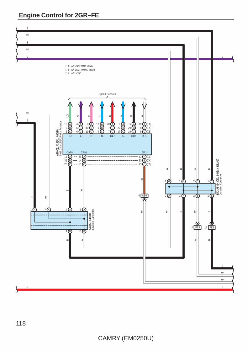
118
CAMRY (EM0250U)
Engine Control for 2GR–FE
R
8 C (∗5)(∗4)B8(∗3)A19
C19B29A5
C17B27A6
C7B7A20
C9B9A17
C10B10A3
C6B6A4
C5B5A18
Speed Sensors
LG V P L R L B W
AB
11 (∗3)
A1 A7
26 C35
B4 B10
A2 A8
A25B14C15
A12(∗4)B33(∗5)C23
FL+ FL– FR+ FR– RL+ RL– RR+ RR–
CANH CANL SP1
AE66
BR
W
2 A 1 A 2 B 1 B
W
2 C 1 C
BW
BWBW
B
W
WB
B W
B W
B
W
Junc
tion
Con
nect
orA4
0(A)
, E41
( B)
W B
Junc
tion
Con
nect
orE4
2(A)
, E43
( B) ,
E44(
C) ,
E62(
G)
Ski
d C
ontro
l EC
U w
ith A
ctua
tor
A25(
C) ,
A26(
A), A
60( B
)V
R
V
W
B
∗ 3 : w/ VSC TMC Made∗ 4 : w/ VSC TMMK Made∗ 5 : w/o VSC
2 G 1 GBW
W
B
14 FE3 13 FE3

CAMRY (EM0250U)
119
R
R
7 IF
LG
R
(BAT)
2
1
10ADOME
12 A
2 3U
7 3Q
V
12 3Q
1 3D
EA1
SB
GR V
W–B
F1
(IG)
12 IG
7. 5AGAUGENO. 2
(BAT)
10AMPX–B
BIG+ B2
E2
3P9
3B3
ID13
3L12
3Q1
R
3G2
3Q9
A13 A1 A2
GR
GR V
2
R
A24
3Q5
3D10
A17
B18
CA34
C7
3
GR
W–B
GR
BR
A41(
A), A
42( B
)
C57
ES
+B(DOME)
Mas
ter
War
ning
DRIVE ICMICRO COMPUTER
Power Supply Circuit
MULTI LCD
W–B
IG2
Mal
func
tion
Indi
cato
r La
mp
B4
CHK
Spe
edom
eter
Buzzer
Junc
tion
Con
nect
or
Junc
tion
Con
nect
or
WB
Com
bina
tion
Met
erF1
( A) ,
F2( B
)
CANLCANH
18 A17 A
IG2
14 B
SI
3P11
3D3
WW
V
10 3B
+S
3 3P
V
B12
IG2
W
W
B
EA115
BR
BR
V
1A3
CANI/F
Tach
omet
er
Tem
p.
120
CAMRY (EM0250U)
Engine Control for 2GR–FE
The engine control system utilizes a microcomputer and maintains overall control of the engine, transaxle etc. An outline ofthe engine control is given here.
1. Input Signals(1) Engine coolant temp. signal circuit
The engine coolant temp. sensor detects the engine coolant temp. and has a built–in thermistor with a resistance whichvaries according to the engine coolant temp. The engine coolant temp. is input into TERMINAL THW of the enginecontrol module as a control signal.
(2) Intake air temp. signal circuitThe intake air temp. sensor is installed in the mass air flow meter and detects the intake air temp., which is input as acontrol signal to TERMINAL THA of the engine control module.
(3) Oxygen sensor signal circuitThe oxygen density in the exhaust emission is detected and is input as a control signal from the heated oxygen sensorsto TERMINALS OX1B and OX2B of the engine control module.
(4) RPM signal circuitCamshaft position is detected by the VVT sensor (Bank 1 exhaust side, bank 1 intake side, bank 2 exhaust side andback 2 intake side), and their signals are input to TERMINALS EV1+, EV2+, VV1+ and VV2+ of the engine controlmodule as control signals. Also, the engine RPM is detected by the crankshaft position sensor installed in the cylinderblock and the signal is input into TERMINAL NE+ of the engine control module as a control signal.
(5) Throttle position sensor signal circuitThe throttle position sensor detects the throttle valve opening angle as a control signal, which is input into TERMINALSVTA1 and VTA2 of the engine control module.
(6) Vehicle speed circuitThe vehicle speed sensor detects the vehicle speed, and the signal is input into TERMINAL SPD of the engine controlmodule via the combination meter, from TERMINAL SP1 of the skid control ECU with actuator.
(7) Battery signal circuitVoltage is constantly applied to TERMINAL BATT of the engine control module. When the power SW is pushed on(Power SW type), or when the ignition SW is turned on (Ignition SW type), the voltage for engine control module start–uppower supply is applied to TERMINAL +B and +B2 of engine control module via EFI relay.
(8) Intake air volume signal circuitThe intake air volume is detected by the mass air flow meter, and is input as a control signal to TERMINAL VG of theengine control module.
(9) Stop lamp SW signal circuitThe stop lamp SW is used to detect whether the vehicle is braking or not, and the signal is input into TERMINAL STP ofthe engine control module as a control signal.
(10)Starter signal circuitTo confirm whether the engine is cranking, the voltage applied to the starter motor when the engine is cranking isdetected, and is input into TERMINAL STA of the engine control module as a control signal.
(11) Engine knock signal circuitEngine knocking is detected by the knock control sensors, and is input into TERMINALS KNK1 and KNK2 of the enginecontrol module as a control signal.
(12)Air fuel ratio signal circuitThe air fuel ratio is detected and input as a control signal into TERMINALS A1A+, A2A+ of the engine control module.
System Outline
CAMRY (EM0250U)
121
2. Control System∗ SFI system
The SFI system monitors the engine condition through the signals input from each sensors to the engine control module.The control signal is sent to the engine control module TERMINALS #10, #20, #30, #40, #50 and #60 to operate theinjector (Fuel injection). The SFI system controls the fuel injection by the engine control module in response to the drivingconditions.
∗ ESA systemThe ESA system monitors the engine condition through the signals input from each sensors to the engine control module.The best ignition timing is decided according to this data and the data memorized in the engine control module. Thecontrol signal is output to TERMINALS IGT1, IGT2, IGT3, IGT4, IGT5 and IGT6, and these signals control the igniter toprovide the best ignition timing.
∗ Heated oxygen sensor heater control systemThe heated oxygen sensor heater control system turns the heater on when the intake air volume is low (Temp. of exhaustemission is low), and warms up the heated oxygen sensors to improve their detection performance. The engine controlmodule evaluates the signals from each sensors, and outputs current to TERMINALS HT1B or HT2B to control the heater.
∗ Air fuel ratio sensor heater control systemThe air fuel ratio sensor heater control system turns the heater on when the intake air volume is low (Temp. of exhaustemission is low), and warms up the air fuel ratio sensor to improve detection performance of the sensor.The engine control module evaluates the signals from each sensor, current is output to TERMINALS HA1A and HA2A,controlling the heater.
∗ ACISThe ACIS includes a valve in the bulkhead separating the surge tank into two parts. This valve is opened and closed inaccordance with the driving conditions to control the intake manifold length in two stages, for increased engine output in allranges from low to high speeds.
∗ ETCS–iThe ETCS–i controls the engine output at its optimal level in accordance with the opening of the accelerator pedal, underall driving conditions.
∗ Dual VVT–iDual VVT–i controls the intake and exhaust valve timing to the most appropriate levels in accordance with the engineconditions.
3. Diagnosis SystemWhen there is a malfunction in the engine control module signal system, the malfunctioning system is recorded in thememory. The malfunctioning system can be found by reading the code displayed on the malfunction indicator lamp.
4. Fail–Safe SystemWhen a malfunction has occurred in any system, there is a possibility of causing engine trouble due to continued controlbased on that system. In that case, the fail–safe system either controls the system using the data (Standard values)recorded in the engine control module memory, or else stops the engine.

122
CAMRY (EM0250U)
Engine Control for 2GR–FE
: Parts Location
Code See Page Code See Page Code See Page
A17 59 C12 50 (2GR–FE) C56 51 (2GR–FE)
A19 59 C13 50 (2GR–FE) C57 51 (2GR–FE)
A25 C 48 (2GR–FE) C14 50 (2GR–FE) E6 A 56
A26 A 48 (2GR–FE) C15 50 (2GR–FE) E7 B 56
A40 A 59 C17 50 (2GR–FE) E8 C 56
A41 A 59 C34 51 (2GR–FE) E9 D 56
A42 B 59 C35 51 (2GR–FE) E10 56
A43 49 (2GR–FE) C36 51 (2GR–FE) E15 56
A53 49 (2GR–FE) C37 51 (2GR–FE) E23 56
A55 A 49 (2GR–FE) C38 51 (2GR–FE) E40 B 57
A56 A 59 C39 51 (2GR–FE) E41 B 57
A57 B 59 C40 51 (2GR–FE) E42 A 57
A58 A 59 C41 51 (2GR–FE) E43 B 57
A60 B 49 (2GR–FE) C42 51 (2GR–FE) E44 C 57
C1 A 50 (2GR–FE) C43 51 (2GR–FE) E50 57
C2 50 (2GR–FE) C44 51 (2GR–FE) E62 G 57
C4 50 (2GR–FE) C45 51 (2GR–FE) F1 A 58
C5 50 (2GR–FE) C46 51 (2GR–FE) F2 B 58
C6 50 (2GR–FE) C47 51 (2GR–FE) N10 60
C7 50 (2GR–FE) C48 51 (2GR–FE) N17 60
C8 50 (2GR–FE) C50 51 (2GR–FE) V1 51 (2GR–FE)
C9 50 (2GR–FE) C51 51 (2GR–FE) V2 51 (2GR–FE)
C10 50 (2GR–FE) C52 51 (2GR–FE)
C11 50 (2GR–FE) C55 B 51 (2GR–FE)
: Relay Blocks
Code See Page Relay Blocks (Relay Block Location)
1 22 Engine Room R/B (Engine Compartment Left)

CAMRY (EM0250U)
123
: Junction Block and Wire Harness Connector
Code See Page Junction Block and Wire Harness (Connector Location)
1A
25Engine Room Main Wire and Engine Room J/B (Engine Compartment Left)
1D 25Engine Room Main Wire and Engine Room J/B (Engine Compartment Left)
1E
25Engine Room Main Wire and Engine Room J/B (Engine Compartment Left)
1G 22
3B
36 Instrument Panel Wire and J/B No.3 (Behind the Combination Meter)
3D
36 Instrument Panel Wire and J/B No.3 (Behind the Combination Meter)
3E
36 Instrument Panel Wire and J/B No.3 (Behind the Combination Meter)
3F
36 Instrument Panel Wire and J/B No.3 (Behind the Combination Meter)3G 36 Instrument Panel Wire and J/B No.3 (Behind the Combination Meter)
3H
36 Instrument Panel Wire and J/B No.3 (Behind the Combination Meter)
3J
3K
3L
3P
36 Instrument Panel No.2 Wire and J/B No.3 (Behind the Combination Meter)3Q 36 Instrument Panel No.2 Wire and J/B No.3 (Behind the Combination Meter)
3U
36 Instrument Panel No.2 Wire and J/B No.3 (Behind the Combination Meter)
4A
42 Instrument Panel Wire and J/B No.4 (Instrument Panel Brace Center)
4C
42 Instrument Panel Wire and J/B No.4 (Instrument Panel Brace Center)
4E
42 Instrument Panel Wire and J/B No.4 (Instrument Panel Brace Center)4F
42 Instrument Panel Wire and J/B No.4 (Instrument Panel Brace Center)4G
42 Instrument Panel Wire and J/B No.4 (Instrument Panel Brace Center)
4K
4L
4M
IC30 Engine Room Main Wire and Instrument Panel J/B (Cowl Side Left)
ID30 Engine Room Main Wire and Instrument Panel J/B (Cowl Side Left)
IF 30
Instrument Panel Wire and Instrument Panel J/B (Cowl Side Left)IG31
Instrument Panel Wire and Instrument Panel J/B (Cowl Side Left)
II31
Instrument Panel Wire and Instrument Panel J/B (Cowl Side Left)
: Connector Joining Wire Harness and Wire Harness
Code See Page Joining Wire Harness and Wire Harness (Connector Location)
AE566 Engine Room Main Wire and Instrument Panel Wire (Instrument Panel Right)
AE666 Engine Room Main Wire and Instrument Panel Wire (Instrument Panel Right)
AE7 66 Engine Room Main Wire and Instrument Panel Wire (Right Side of the Instrument Panel J/B)
CA1
64 (2GR–FE) Engine Wire and Engine Room Main Wire (Inside of the Engine Room R/B and Engine Room J/B)CA2 64 (2GR–FE) Engine Wire and Engine Room Main Wire (Inside of the Engine Room R/B and Engine Room J/B)
CA3
64 (2GR–FE) Engine Wire and Engine Room Main Wire (Inside of the Engine Room R/B and Engine Room J/B)
CV1 64 (2GR–FE) Engine Wire and Sensor Wire (Left Side of the Cylinder Block)
EA1 66 Instrument Panel Wire and Engine Room Main Wire (Left Kick Panel)
FE3 66 Instrument Panel No.2 Wire and Instrument Panel Wire (Instrument Panel Center)
NA1 66 Floor Wire and Engine Room Main Wire (Left Kick Panel)

124
CAMRY (EM0250U)
Engine Control for 2GR–FE
: Ground Points
Code See Page Ground Points Location
A164 (2GR–FE) Front Left Fender
A264 (2GR–FE) Front Left Fender
A3 66 Left Cowl Side Panel
C4 64 (2GR–FE) Cylinder Head
C5 64 (2GR–FE) Right Side of the Cylinder Block
C7 64 (2GR–FE) Left Side of the Cylinder Block
F1 66 Instrument Panel Left
N1 67 Left Rear Quarter Panel

CAMRY (EM0250U)
125
Memo

126
CAMRY (EM0250U)
Engine Control for 2AZ–FE
1
(BAT)
1E
Pum
p
1E 1E
A1
7 1E
M
N1
5
4
BR
N10
1E
2
1
6 11
1D
1E
YB
2
(IG)
IG9
GR
W–B
12
10AEFINO. 3
10AIGN
30AEFI MAIN
15AEFINO. 2
2
1
1
1
R
1
3F12
3K12
B6
A1
1E9
EFIRelay
L O
R GR
12
813
YY
LG
LG
A58(
A), E
40( B
)
YGR
NA19
W–B
CA21
15AINJ
BR
IH8
(IG)
EA11
CA12C/OPNRelay
W
BR
W
Junc
tion
Con
nect
or
Fuel
Suc
tion
Pum
pan
d G
age
Ass
embl
y
Y
O
GR
R
R
W
W
W–B
1E10
A17
B16
A3
Junc
tion
Con
nect
orA4
1(A)
, A42
( B)
BR
W–B
W–B
BR
W–B
GR
GR
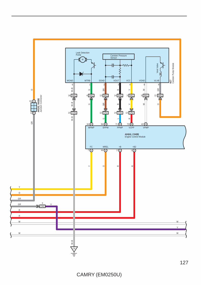
CAMRY (EM0250U)
127
A2 A1
+B2+B
R R
VCCVOUTSGND
Leak DetectionPump
M
VGNDMTRB
1 9
Canister PressureSensor
Ven
t Val
ve
VLVB
8
44
MREL
A7
FC
A
OY
W
V
W
6 4
MGND
3
N17
2
NA114 NA13NA113
CA214 CA21312 CA2
BR YB
B YBR
G RL
71 B 70 B
EPPM VCPPPPMP
94 B
NA116
CA310
C6
W–B
W–B
W–B
W–B
NA15NA14
G WWG
MPMP VPMP
42 A34 A
B1
A10
NA112
GR
GR
O
A41(
A), A
42( B
)
A24(A), C24(B)
O
Engine Control Module
Junc
tion
Con
nect
or
Can
iste
r P
ump
Mod
ule
Y
O
GR
R
R
W
W
GRCA2
3 V

128
CAMRY (EM0250U)
Engine Control for 2AZ–FE
2
1
EPAVPAVCPAEPA2VPA2VCP2
BA 57 55A
R GL
EPA2
A
EPA
60
VCP2 VCPA
59
VPA2 VPA
O
56
Y
A58 AA
A17
6 5431 2
W
W W W W
L Y R B
B105 B106 B107 B108
# 40 # 30 # 20 # 10
W W
3 A
V
B49
2
+BM
B118 B116 B65 B88
VO SB W P Y
1
LG
B–R
(BAT)
V
V
C2
VG E2G THA E2
+B
3
5 4 1 2
PRG VG E2G THA ETHA
A24(A), C24(B)
20 A
BATT
Y
10AEFINO. 1
1A2
(BAT)
A8 A9
10AETCS
W
A41(A)
50 B
L
ALT
Accelerator Position Sensor
Engine Control Module
JunctionConnector
Mass Air Flow Meter
W
V
W
B–R
B3
M
GeneratorC18(B)
FuelInjector(No. 1)
C7FuelInjector(No. 2)
C9C8FuelInjector(No. 3)
C10FuelInjector(No. 4)
VSV(Purge)
C6
2222
1111

CAMRY (EM0250U)
129
VTA2
G
1
3 4
2
G R
VTAL P
1
2
1
67 B B91B115 B114
GE01M–M+VCTA ETA
C5
VTA1
M–M+E2VTA2VC
Y
( Shi
elde
d)
PB
W–L
1
W
B
A1A+
G2+
( Shi
elde
d)
98
A1A–
B
G2–
3
109 BB113112 B87 B64 B47 B
2
2
3 4
1
BR
2
R
2
G
121 B
HA1A+B
LG
Y
63
+B
122 B
BR
1
NE–NE+
5
OX1B
( Shi
elde
d)
E2
99
HT1B
B
WB–R
HT1B HA1AA1A–A1A+EX1BOX1B
C15
C22
41 B
46
( Shi
elde
d)
( Shi
elde
d)
C31
B42C
20
OC1+
G–R
123 B100 B
OC1–
W B
C32
P
97 B B96
THW ETHW
B
2
1
(Shielded)
(Shielded)
LG G
Air
Fuel
Rat
io S
enso
r( B
ank
1 S
enso
r 1)
Cra
nksh
aft
Pos
ition
Sen
sor
Hea
ted
Oxy
gen
Sen
sor
( Ban
k 1
Sen
sor
2)
Cam
shaf
tP
ositi
on S
enso
r
Cam
shaf
t Tim
ing
Oil
Con
trol V
alve
Throttle Body Assembly
Eng
ine
Coo
lant
Tem
p.
Sen
sor
C4
(Shielded)
(Shielded)
B–R
W
Engine Control ModuleA24(A), C24(B)

130
CAMRY (EM0250U)
Engine Control for 2AZ–FE
84 B
L
85 B
IGF1
B110
1
2
( Shi
elde
d)
RG
EKNKKNK1
111 B
83 B 82 BB81
W
IGT4IGT3IGT2IGT1
LGG–R G
C30
B
BR
BR
PSW
53 A
IAC–IACAVCIA
5213
C33
L
L
B–WB
33 A126 B93 B A52W
4
103
CA219
A21
FANL
R
22 A
W
FANH
FAN
NO
. 3 R
elay
9 CA2
IAC+EIA
1
CA32
CA31
W–B
B–W
W G
( ∗1)
( ∗1)
( ∗1)
( ∗1)
( ∗1)
( ∗1)
( ∗1)
3 CA3B
C17
Pow
er S
teer
ing
Oil
Pre
ssur
e S
W
Kno
ck C
ontro
lS
enso
r ( B
ank
1)
Intake Air Control Valve
M
VCIA IACA EIA IAC+ IAC–
(Shielded)
(Shielded)
(Shielded)
(Shielded)
FAN
NO
. 1 R
elay
FAN
NO
. 2 R
elay
IGT4
33
IGT1
W
3
IGT2
G–R
3
C11 IGT3
G LG
C13
C12
C14IGF
2
W–L
IGF
2
W–L
IGF
2
W–L
IGF
2
W–L
W–L
W–L
W–L
Igni
tion
Coi
l( N
o. 1
)
Igni
tion
Coi
l( N
o. 3
)
Igni
tion
Coi
l( N
o. 2
)
Igni
tion
Coi
l( N
o. 4
)
B–W
Engine Control ModuleA24(A), C24(B)
∗ 1 : California
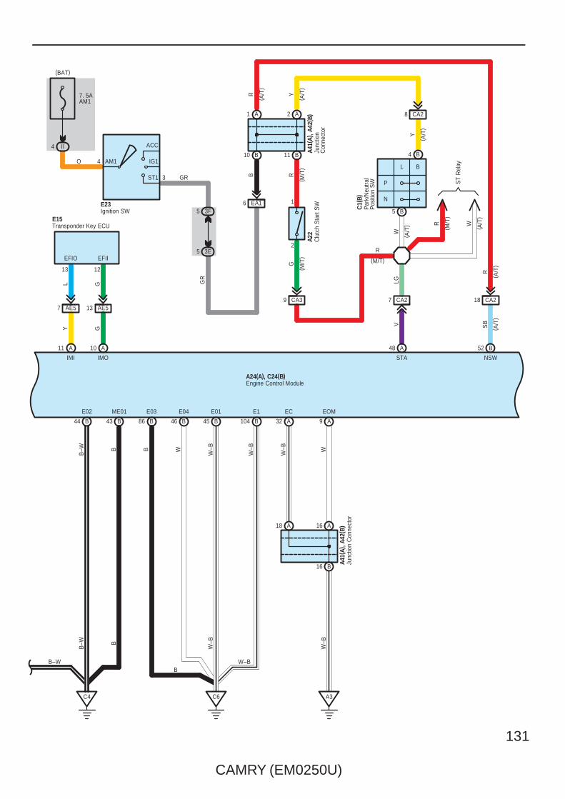
CAMRY (EM0250U)
131
B104
E1
W–B
W–B
E01
45 BB46
E04
WB
ME01
43 BB44
E02
B–W
86
B
B
B
E03
C4 C6
B–W W–B
W–B
B–W
STA
A48
V
NSW
B52
SB
B16
A18 A16
A9
EOM
A32
EC
A3
A41(
A), A
42( B
)
W–B W
W–B
Junc
tion
Con
nect
or
L G
AE57 13 AE5
EFIIEFIO
1213
11 10
GY
AA
IMOIMI
Transponder Key ECUE15
18 CA2
CA2
P
N
BL4
3
AM1
ACC
IG1
ST1
R
A22
8
B
C1(
B)
W
7 CA2
5 B
4 B
2
1
CA39
EA16
Y
LG
( A/T
)
( A/T
)
( A/T
)
R
( M/T
)
G
( M/T
)
Clu
tch
Sta
rt S
W Par
k/N
eutra
lP
ositi
on S
W
GR
B10 B11
A1 A2
7. 5AAM1
II4
O
ST
Rel
ay
R
(M/T)
3F5
3E5
GR
R W
(BAT)
( A/T
)
( M/T
)
( A/T
)
YR
( A/T
)
( A/T
)
Junc
tion
Con
nect
or
A41(
A), A
42( B
)
Ignition SWE23
Engine Control ModuleA24(A), C24(B)
B

132
CAMRY (EM0250U)
Engine Control for 2AZ–FE
R
W
BR
24 A
A24(A), C24(B)
AE55
Engine Control Module
B
P
AE512
8
L
A
SPD
15
B
A
TACH
27
P
A
TC
AE56
A49 A41
CANL CANH
W B
W
B
3H5
3B5
146
139
Dat
a Li
nkC
onne
ctor
3
E10
P
TAC TC
CANLCANH
B
W
V
W
B
AE514
Junc
tion
Con
nect
or
Sto
p La
mp
SW
A58(
A), E
40( B
)
BY Y
Y
6 B
2 A
12 3K
12 3F
35 28
(IG)
A19
GR
A
ST1–
9 IG
10AIGN
IGSW
A
Y
ID1
A
STP
10ASTOP
IC8
(BAT)W
B
36
B
R
1 4
2 3
V

CAMRY (EM0250U)
133
R
8 C (∗4)(∗3)B8(∗2)A19
C19B29A5
C17B27A6
C7B7A20
C9B9A17
C10B10A3
C6B6A4
C5B5A18
Speed Sensors
LG V P L R L B W
AB
11 (∗2)
A1 A7
26 C35
B4 B10
A2 A8
A25B14C15
A12(∗3)B33(∗4)C23
FL+ FL– FR+ FR– RL+ RL– RR+ RR–
CANH CANL SP1
AE66
BR
W
2 A 1 A 2 B 1 B
W
2 G 1 G
BW
BWBW
B
W
WB
B W
B W
B
W
Junc
tion
Con
nect
orA4
0(A)
, E41
( B)
W B
Junc
tion
Con
nect
orE4
2(A)
, E43
( B) ,
E62(
G)
Ski
d C
ontro
l EC
U w
ith A
ctua
tor
A25(
C) ,
A26(
A), A
60( B
)
VV
W
B
∗ 3 : w/ VSC TMMK Made∗ 2 : w/ VSC TMC Made
∗ 4 : w/o VSC
R
14 FE3 13 FE3
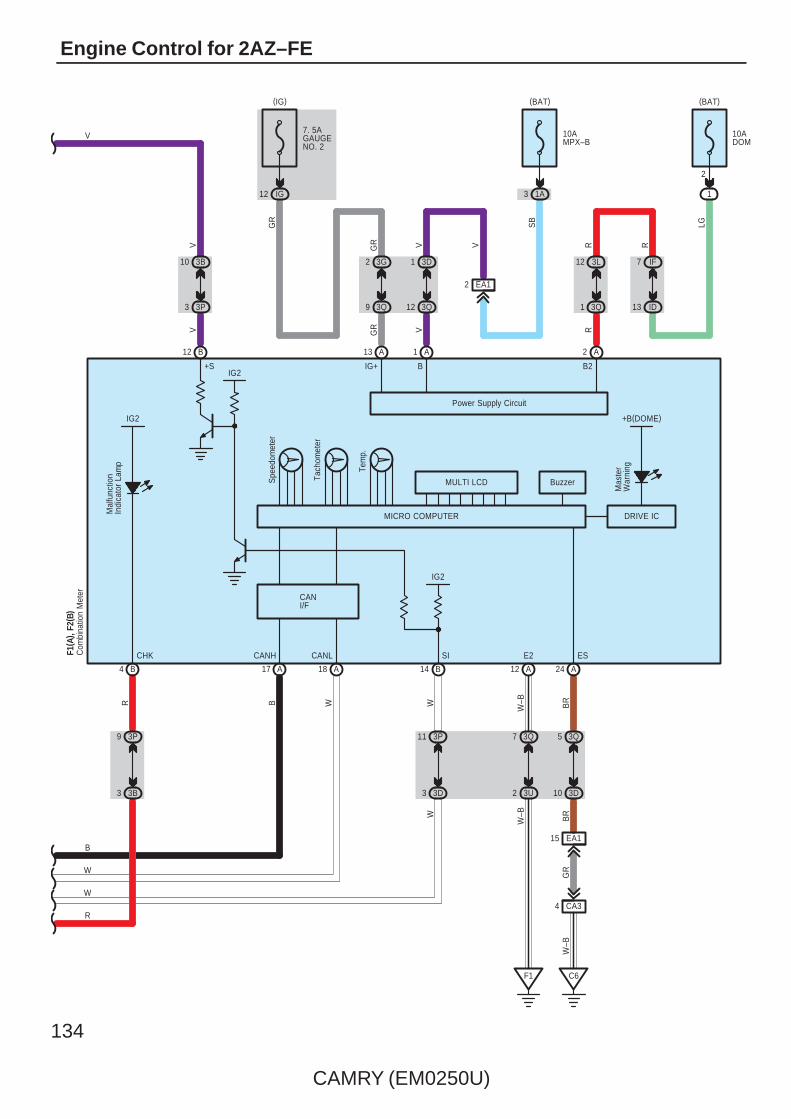
134
CAMRY (EM0250U)
Engine Control for 2AZ–FE
4 CA3
A24
3Q5
3D10
15 EA1
BR
C6
BR
GR
W–B
BuzzerSpe
edom
eter
CHK
4 B
Mal
func
tion
Indi
cato
r La
mp
IG2
W–B
MULTI LCD
Power Supply Circuit
MICRO COMPUTER DRIVE IC
Mas
ter
War
ning
+B(DOME)
ESR
2
VGR
GR
2 A1 A13 A
9 3Q
2 3G
R
1 3Q
12 3L
13 ID
3 3B
9 3P
E2
B2IG+ B
10AMPX–B
(BAT)
7. 5AGAUGENO. 2
IG12
(IG)
F1
W–B
VGR
SB
EA1
3D1
3Q12
V
3Q7
3U2
A12
10ADOME
1
2
(BAT)
R
LG
IF7
R
R
WB
Com
bina
tion
Met
erF1
( A) ,
F2( B
)
CANLCANH
18 A17 A
IG2
14 B
SI
3P11
3D3
WW
V
10 3B
+S
3 3P
V
B12
IG2
W
W
B
V
1A3
CANI/F
Tach
omet
er
Tem
p.
CAMRY (EM0250U)
135
The engine control system utilizes a microcomputer and maintains overall control of the engine, transaxle etc. An outline ofthe engine control is given here.
1. Input Signals(1) Engine coolant temp. signal circuit
The engine coolant temp. sensor detects the engine coolant temp. and has a built–in thermistor with a resistance, whichvaries according to the engine coolant temp.. The engine coolant temp. which is input into TERMINAL THW of theengine control module as a control signal.
(2) Intake air temp. signal circuitThe intake air temp. sensor is installed in the mass air flow meter and detects the intake air temp. which is input as acontrol signal to TERMINAL THA of the engine control module.
(3) Oxygen density signal circuitThe oxygen density in the exhaust emission is detected by the heated oxygen sensor and input as a control signal toTERMINAL OX1B of the engine control module.
(4) RPM signal circuitCamshaft position and crankshaft position are detected by the camshaft position sensor and crankshaft position sensor.Camshaft position is input as a control signal to TERMINAL G2+ of the engine control module, and engine RPM is inputinto TERMINAL NE+.
(5) Throttle position signal circuitThe throttle position sensor detects the throttle valve opening angle as a control signal, which is input into TERMINALSVTA1 and VTA2 of the engine control module.
(6) Vehicle speed circuitThe vehicle speed sensor, detects the vehicle speed and input to speed sensor of the skid control ECU with actuator,from skid control ECU with actuator to TERMINAL SPD of the engine control module, Via combination meter.
(7) Battery signal circuitVoltage is constantly applied to TERMINAL BATT of the engine control module. With the ignition SW turned on, thevoltage for engine control module start–up power supply is applied to TERMINALS +B and +B2 of the engine controlmodule via the EFI relay.
(8) Stop lamp SW signal circuitThe stop lamp SW is used to detect whether the vehicle is braking or not and the signal is input into TERMINAL STP ofthe engine control module as a control signal.
(9) Starter signal circuitTo confirm whether the engine is cranking, the voltage is applied to the starter motor during cranking is detected and thesignal is input into TERMINAL STA of the engine control module as a control signal.
(10)Engine knock signal circuitEngine knocking is detected by knock sensor and the signal is input into TERMINAL KNK1 as a control signal.
(11) Air fuel ratio signal systemThe air fuel ratio is detected and input as a control signal into TERMINAL A1A+ of the engine control module.
System Outline

136
CAMRY (EM0250U)
Engine Control for 2AZ–FE
2. Control System∗ SFI system
The SFI system monitors the engine condition through the signals input from each sensor to the engine control module.And the control signal is output to TERMINALS #10, #20, #30, #40 of the engine control module to operate the fuelinjector (Inject the fuel). The SFI system controls the fuel injection operation by the engine control module in response tothe driving conditions.
∗ ESA systemThe ESA system monitors the engine condition through the signals input to the engine control module from each sensor.The best ignition timing is decided according to this data and the memorized data in the engine control module and thecontrol signal is output to TERMINALS IGT1, IGT2, IGT3, IGT4. This signal controls the igniter to provide the bestignition timing for the driving conditions.
∗ Heated oxygen sensor heater control systemThe heated oxygen sensor heater control system turns the heater on when the intake air volume is low (Temp. ofexhaust emissions is low), and warms up the heated oxygen sensor to improve detection performance of the sensor.The engine control module evaluates the signals from each sensor, and outputs current to TERMINAL HT1B to controlthe heater.
3. Diagnosis SystemWith the diagnosis system, when there is a malfunction in the engine control module signal system, the malfunctioningsystem is recorded in the memory. The malfunctioning system can be found by reading the code displayed by themalfunction indicator lamp.
4. Fail–Safe SystemWhen a malfunction has occurred in any system, if there is a possibility of engine trouble being caused by continued controlbased on the signals from that system, the fail–safe system either controls the system by using data (Standard values)recorded in the engine control module memory or else stops the engine.
: Parts Location
Code See Page Code See Page Code See Page
A17 59 C7 54 (2AZ–FE) C32 55 (2AZ–FE)
A19 59 C8 54 (2AZ–FE) C33 55 (2AZ–FE)
A22 59 C9 54 (2AZ–FE) E10 56
A24 A 52 (2AZ–FE) C10 54 (2AZ–FE) E15 56
A25 C 52 (2AZ–FE) C11 54 (2AZ–FE) E23 56
A26 A 52 (2AZ–FE) C12 54 (2AZ–FE) E40 B 57
A40 A 59 C13 54 (2AZ–FE) E41 B 57
A41 A 59 C14 54 (2AZ–FE) E42 A 57
A42 B 59 C15 54 (2AZ–FE) E43 B 57
A58 A 59 C17 54 (2AZ–FE) E62 G 57
A60 B 53 (2AZ–FE) C18 B 54 (2AZ–FE) F1 A 58
C1 B 54 (2AZ–FE) C20 55 (2AZ–FE) F2 B 58
C2 54 (2AZ–FE) C22 55 (2AZ–FE) N10 60
C4 54 (2AZ–FE) C24 B 55 (2AZ–FE) N17 60
C5 54 (2AZ–FE) C30 55 (2AZ–FE)
C6 54 (2AZ–FE) C31 55 (2AZ–FE)
: Relay Blocks
Code See Page Relay Blocks (Relay Block Location)
1 22 Engine Room R/B (Engine Compartment Left)
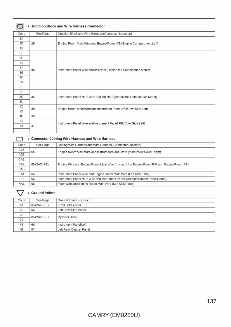
CAMRY (EM0250U)
137
: Junction Block and Wire Harness Connector
Code See Page Junction Block and Wire Harness (Connector Location)
1A
25 Engine Room Main Wire and Engine Room J/B (Engine Compartment Left)1D 25 Engine Room Main Wire and Engine Room J/B (Engine Compartment Left)
1E
25 Engine Room Main Wire and Engine Room J/B (Engine Compartment Left)
3B
36 Instrument Panel Wire and J/B No.3 (Behind the Combination Meter)
3D
36 Instrument Panel Wire and J/B No.3 (Behind the Combination Meter)
3E
36 Instrument Panel Wire and J/B No.3 (Behind the Combination Meter)3F
36 Instrument Panel Wire and J/B No.3 (Behind the Combination Meter)3G
36 Instrument Panel Wire and J/B No.3 (Behind the Combination Meter)
3H
3K
3L
3P
36 Instrument Panel No.2 Wire and J/B No.3 (Behind the Combination Meter)3Q 36 Instrument Panel No.2 Wire and J/B No.3 (Behind the Combination Meter)
3U
36 Instrument Panel No.2 Wire and J/B No.3 (Behind the Combination Meter)
IC30 Engine Room Main Wire and Instrument Panel J/B (Cowl Side Left)
ID30 Engine Room Main Wire and Instrument Panel J/B (Cowl Side Left)
IF 30
Instrument Panel Wire and Instrument Panel J/B (Cowl Side Left)IG
31Instrument Panel Wire and Instrument Panel J/B (Cowl Side Left)
IH 31Instrument Panel Wire and Instrument Panel J/B (Cowl Side Left)
II
31
: Connector Joining Wire Harness and Wire Harness
Code See Page Joining Wire Harness and Wire Harness (Connector Location)
AE566 Engine Room Main Wire and Instrument Panel Wire (Instrument Panel Right)
AE666 Engine Room Main Wire and Instrument Panel Wire (Instrument Panel Right)
CA1
65 (2AZ–FE) Engine Wire and Engine Room Main Wire (Inside of the Engine Room R/B and Engine Room J/B)CA2 65 (2AZ–FE) Engine Wire and Engine Room Main Wire (Inside of the Engine Room R/B and Engine Room J/B)
CA3
65 (2AZ–FE) Engine Wire and Engine Room Main Wire (Inside of the Engine Room R/B and Engine Room J/B)
EA1 66 Instrument Panel Wire and Engine Room Main Wire (Left Kick Panel)
FE3 66 Instrument Panel No.2 Wire and Instrument Panel Wire (Instrument Panel Center)
NA1 66 Floor Wire and Engine Room Main Wire (Left Kick Panel)
: Ground Points
Code See Page Ground Points Location
A1 65 (2AZ–FE) Front Left Fender
A3 66 Left Cowl Side Panel
C465 (2AZ–FE) Cylinder Block
C665 (2AZ–FE) Cylinder Block
F1 66 Instrument Panel Left
N1 67 Left Rear Quarter Panel
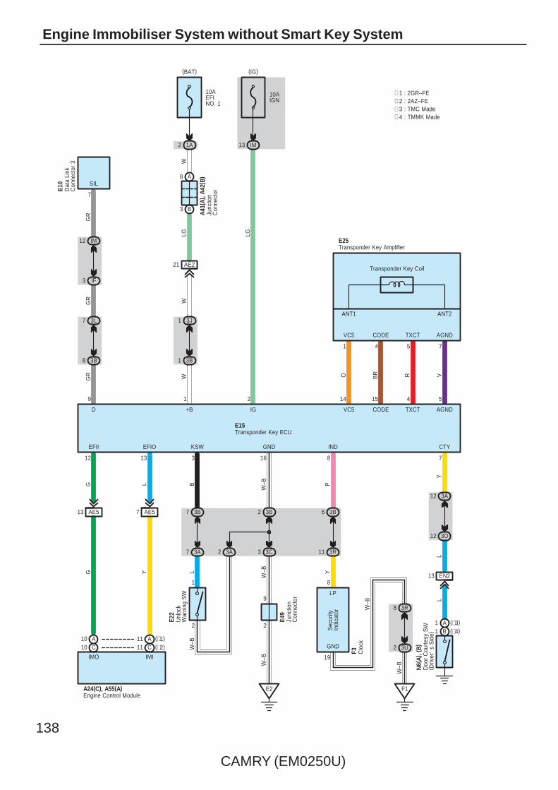
138
CAMRY (EM0250U)
Engine Immobiliser System without Smart Key System
A41(
A), A
42( B
)
7 AE5
2
13 AE5
W
VC5
29 1 14 15 4 5
1312 3 7816
E2
Transponder Key Coil
TXCT AGND
EFIOEFII KSW CTYINDGND
ANT1 ANT2
1
CODE
4 5 7O BR R
G
E15
VC5
E25
IGD +B CODE TXCT AGND
(IG)
IM13
10AIGN
(BAT)
1A
10AEFINO. 1
1 3B
1 3J
V
L B
Y
P
W–B
3 3C
2 3B
W–B
W
LG
W
GR
Y
A8
B3
LG
G
2
9
W–B
E49
Junc
tion
Con
nect
or
Transponder Key ECU
Transponder Key Amplifier
Junc
tion
Con
nect
or
3L7
3B8
IM12
IF3
GR
GR
7
SIL
Dat
a Li
nkC
onne
ctor
3
E10
∗ 1 : 2GR–FE∗ 2 : 2AZ–FE
C10A10
(∗2)C11(∗1)A11
Engine Control ModuleA24(C), A55(A)
2
1
3B7
3A7 3A2
3B6
3R11
19
8
LP
GND
3R8
3U2
F1
3A12
3O12
EN213
Clo
ckF3
LW
–B
Unl
ock
War
ning
SW
E22
YS
ecur
ityIn
dica
tor W
–B
W–B
LL
IMO IMI
∗ 3 : TMC Made∗ 4 : TMMK Made
(∗4)B1(∗3)A1
Doo
r C
ourte
sy S
W( D
river
's
Sid
e)
N6(
A), (
B)
AE221

CAMRY (EM0250U)
139
: Parts Location
Code See Page Code See Page Code See Page
A24 C 52 (2AZ–FE) E10 56 E49 57
A41 A 59 E15 56 F3 58
A42 B 59 E22 56N6
A 60
A55 A 49 (2GR–FE) E25 56N6
B 60
: Junction Block and Wire Harness Connector
Code See Page Junction Block and Wire Harness (Connector Location)
1A 25 Engine Room Main Wire and Engine Room J/B (Engine Compartment Left)
3A
36 Instrument Panel Wire and J/B No.3 (Behind the Combination Meter)
3B
36 Instrument Panel Wire and J/B No.3 (Behind the Combination Meter)3C
36 Instrument Panel Wire and J/B No.3 (Behind the Combination Meter)3J
36 Instrument Panel Wire and J/B No.3 (Behind the Combination Meter)
3L
3O
3R36 Instrument Panel No.2 Wire and J/B No.3 (Behind the Combination Meter)
3U36 Instrument Panel No.2 Wire and J/B No.3 (Behind the Combination Meter)
IF30 Instrument Panel Wire and Instrument Panel J/B (Cowl Side Left)
IM30 Instrument Panel Wire and Instrument Panel J/B (Cowl Side Left)
: Connector Joining Wire Harness and Wire Harness
Code See Page Joining Wire Harness and Wire Harness (Connector Location)
AE2 68 Engine Room Main Wire and Instrument Panel Wire (Right Side of the Instrument Panel J/B)
AE5 66 Engine Room Main Wire and Instrument Panel Wire (Instrument Panel Right)
EN2 66 Instrument Panel Wire and Floor Wire (Left Kick Panel)
: Ground Points
Code See Page Ground Points Location
E2 66 Instrument Panel Brace LH
F1 66 Instrument Panel Left
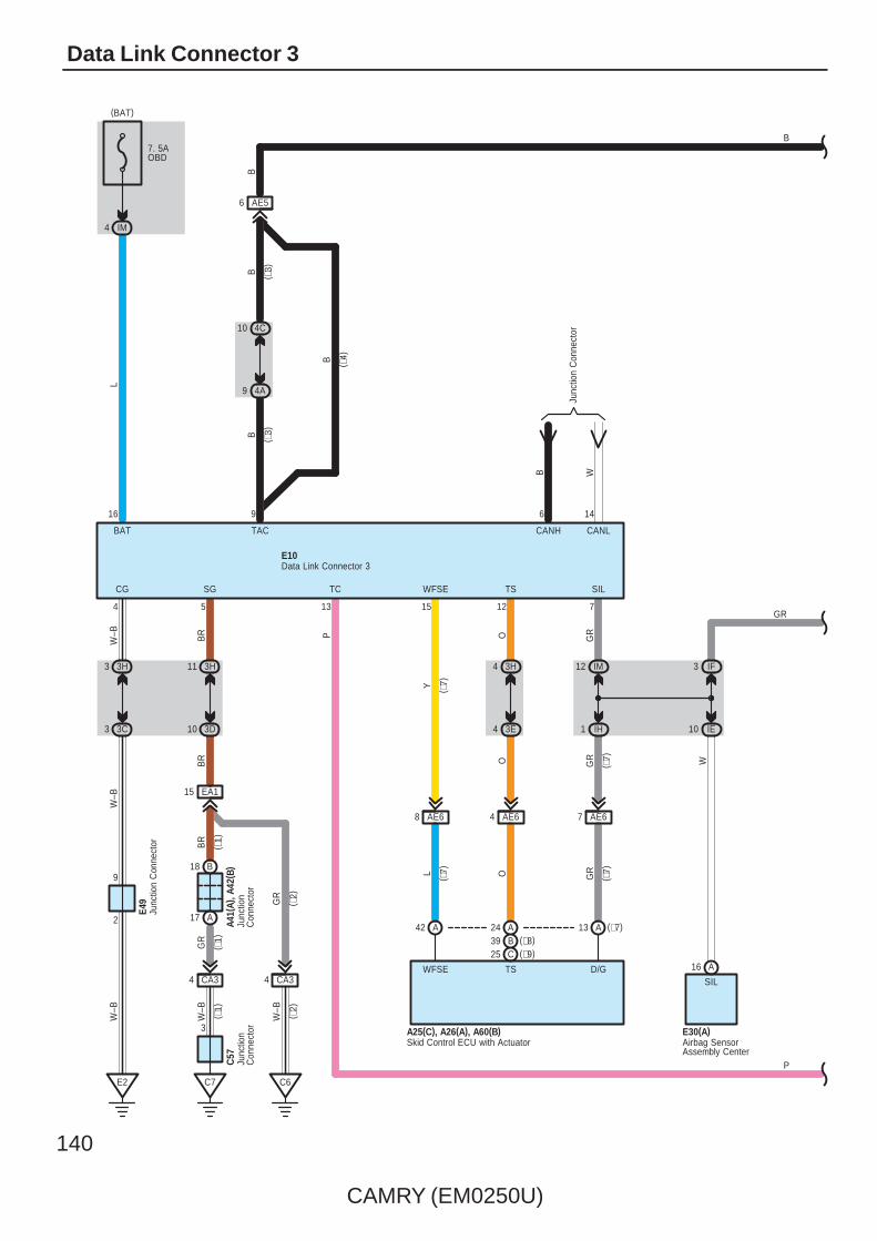
140
CAMRY (EM0250U)
Data Link Connector 3
CANL
3 IF
Y
O GR
Junc
tion
Con
nect
or
GR
W
1 IH
12 IM
( ∗7)
6
C7
10 3D
11 3H
E2
3 3C
3 3H
SIL
12
TS
14
CANH
7
GR
(BAT)
IM4
7. 5AOBD
CG
BAT
4
16
L
BR
W–B
5
SG WFSE
15
TAC
9
W–B
BR
BR
E10
IE10
P
TC
13
( ∗1)
( ∗1)
EA115
B18
A17
CA34
3
GR
W–B
CA34
C6
A41(
A), A
42( B
)C
57
GR
W–B
2
9
E49
W–B
( ∗1)
( ∗2)
( ∗2)
3H4
3E4
O
Junc
tion
Con
nect
orJu
nctio
nC
onne
ctor
Data Link Connector 3
Junc
tion
Con
nect
or
4C10
4A9
AE56
(∗7)A13
C25B39A24A42
AE68 AE64 AE67
WFSE TS D/G
Skid Control ECU with ActuatorA25(C), A26(A), A60(B)
A16
SIL
P
B W
O GRL ( ∗7)
Airbag SensorAssembly Center
E30(A)
B ( ∗4)
B ( ∗3)
B ( ∗3)
B
(∗8)(∗9)
( ∗7)
( ∗7)
B
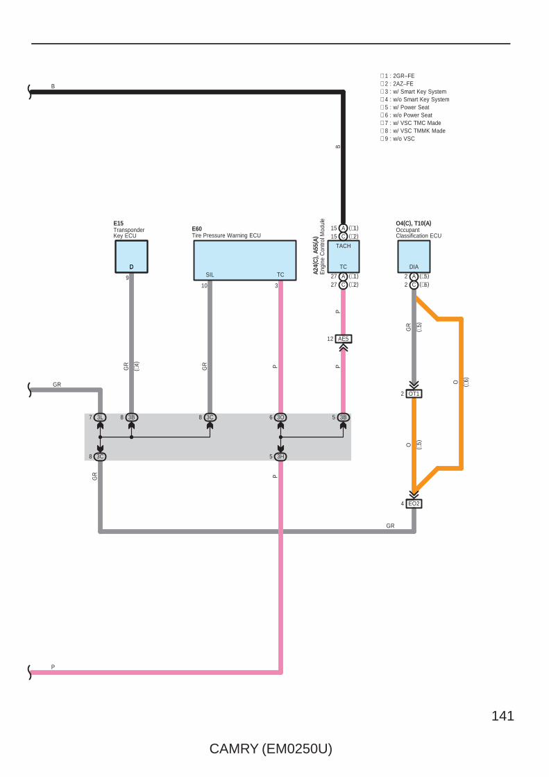
CAMRY (EM0250U)
141
GR PGR
8 3C
GR
7 3L
( ∗4)
∗ 3 : w/ Smart Key System
P
3H5
∗ 1 : 2GR–FE
3C8
P
3O63B8
∗ 2 : 2AZ–FE
9
D
TransponderKey ECU
E15
3B5
DD TC
A27C27
(∗2)C15(∗1)A15
TACH
SIL TC
310
Tire Pressure Warning ECUE60
O4(C), T10(A)OccupantClassification ECU
DIA
(∗5)A2(∗6)C2
EO24
GR
( ∗5)
O ( ∗5)
O ( ∗6)
P
GR
B
∗ 4 : w/o Smart Key System∗ 5 : w/ Power Seat∗ 6 : w/o Power Seat∗ 7 : w/ VSC TMC Made∗ 8 : w/ VSC TMMK Made∗ 9 : w/o VSC
GR
BP
Eng
ine
Con
trol M
odul
eA2
4(C
) , A5
5(A)
(∗1)(∗2)
OT12
AE512

142
CAMRY (EM0250U)
Data Link Connector 3
: Parts Location
Code See Page Code See Page Code See Page
A24 C 52 (2AZ–FE) A42 B 59 E15 56
A25 C48 (2GR–FE) A55 A 49 (2GR–FE) E30 A 56
A25 C52 (2AZ–FE)
A60 B49 (2GR–FE) E49 57
A26 A48 (2GR–FE)
A60 B53 (2AZ–FE) E60 57
A26 A52 (2AZ–FE) C57 51 (2GR–FE) O4 C 63 (*2)
A41 A 59 E10 56 T10 A 62 (*1)
: Junction Block and Wire Harness Connector
Code See Page Junction Block and Wire Harness (Connector Location)
3B
36 Instrument Panel Wire and J/B No.3 (Behind the Combination Meter)
3C
36 Instrument Panel Wire and J/B No.3 (Behind the Combination Meter)
3D
36 Instrument Panel Wire and J/B No.3 (Behind the Combination Meter)3E 36 Instrument Panel Wire and J/B No.3 (Behind the Combination Meter)
3H
36 Instrument Panel Wire and J/B No.3 (Behind the Combination Meter)
3L
3O
4A42 Instrument Panel Wire and J/B No.4 (Instrument Panel Brace Center)
4C42 Instrument Panel Wire and J/B No.4 (Instrument Panel Brace Center)
IE30
Instrument Panel Wire and Instrument Panel J/B (Cowl Side Left)IF
30
Instrument Panel Wire and Instrument Panel J/B (Cowl Side Left)IH 31
Instrument Panel Wire and Instrument Panel J/B (Cowl Side Left)
IM 30
: Connector Joining Wire Harness and Wire Harness
Code See Page Joining Wire Harness and Wire Harness (Connector Location)
AE566 Engine Room Main Wire and Instrument Panel Wire (Instrument Panel Right)
AE666 Engine Room Main Wire and Instrument Panel Wire (Instrument Panel Right)
CA364 (2GR–FE)
Engine Wire and Engine Room Main Wire (Inside of the Engine Room R/B and Engine Room J/B)CA365 (2AZ–FE)
Engine Wire and Engine Room Main Wire (Inside of the Engine Room R/B and Engine Room J/B)
EA1 66 Instrument Panel Wire and Engine Room Main Wire (Left Kick Panel)
EO2 66 Instrument Panel Wire and Floor No.2 Wire (Right Kick Panel)
OT1 68 (*1) Floor No.2 Wire and Front Seat RH Wire (Under the Front Passenger’s Seat)
: Ground Points
Code See Page Ground Points Location
C6 65 (2AZ–FE) Cylinder Block
C7 64 (2GR–FE) Left Side of the Cylinder Block
E2 66 Instrument Panel Brace LH
* 1 : w/ Power Seat * 2 : w/o Power Seat

CAMRY (EM0250U)
143
Memo
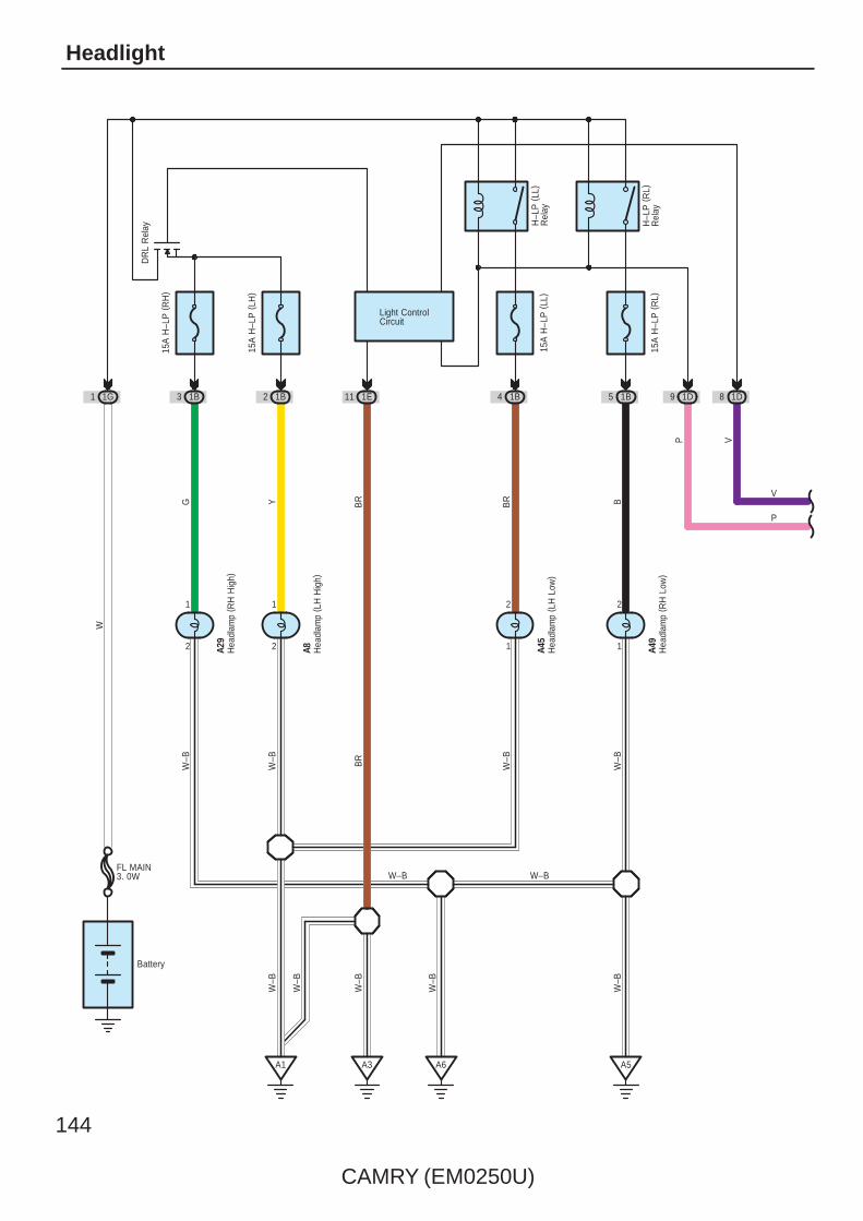
144
CAMRY (EM0250U)
Headlight
Battery
1G1
W
1
2
15A
H–L
P (
LH)
W–B
Y
1B23 1B
DR
L R
elay
5
W–B
W–B
GW
–B
15A
H–L
P (
RH
)
11 1E 4
VP
15A
H–L
P (
LL)
1B 1B
15A
H–L
P (
RL)
BBR
A1 A6
8 1D
W–B
W–B
9 1D
Light ControlCircuit
BR
BR
H–L
P (
RL)
Rel
ay
W–B
W–B
H–L
P (
LL)
Rel
ay
W–B
W–B
A3
2
1
A5
1
2
1
2
Hea
dlam
p ( R
H H
igh)
A29
Hea
dlam
p ( L
H H
igh)
A8 Hea
dlam
p ( L
H L
ow)
A45
Hea
dlam
p ( R
H L
ow)
A49
W–B
V
P
FL MAIN3. 0W
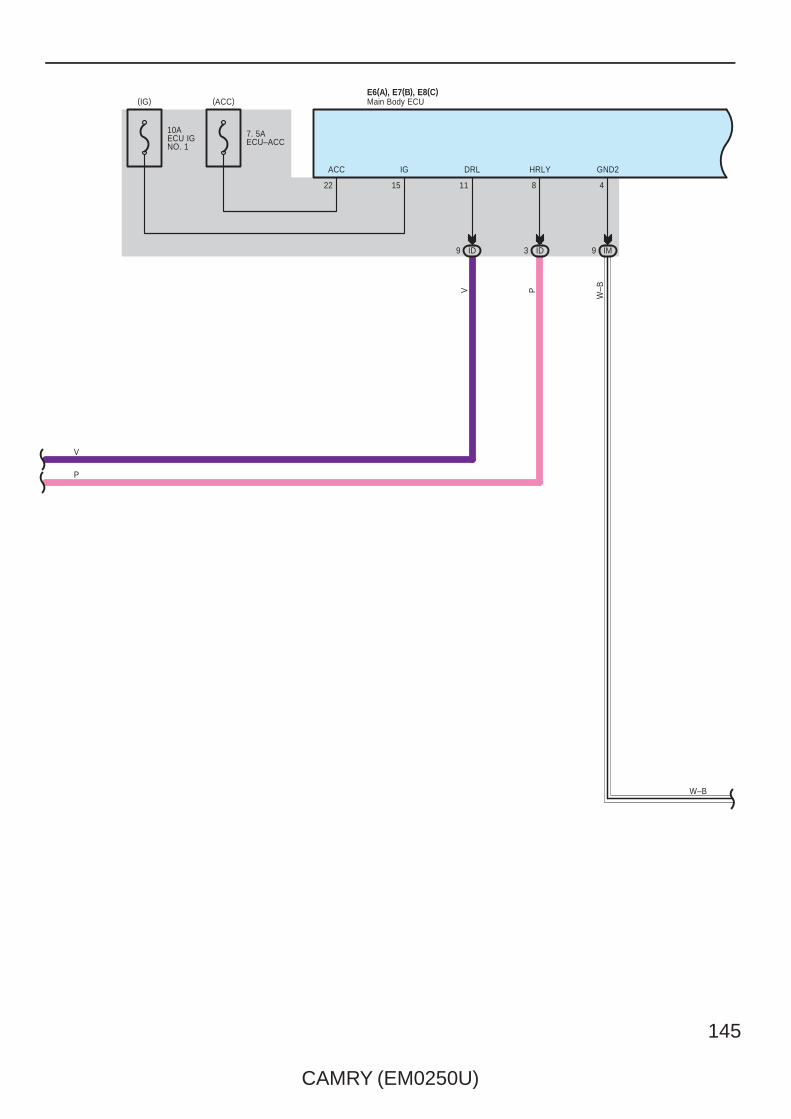
CAMRY (EM0250U)
145
HRLYDRL
811
PV
3 ID9 ID IM9
GND2
4
W–B
E6(A), E7(B), E8(C)Main Body ECU
ACC
22
IG
15
7. 5AECU–ACC
(ACC)(IG)
10AECU IGNO. 1
V
P
W–B

146
CAMRY (EM0250U)
Headlight
12
201117
B13
3N9
3G12
IG5
A17
R
LG
PP
HF HU HEAD
E2
3G3
3C3
2
9
W–B
W–B
W–B
DRL–OFF(USA)OFF (ExceptUSA)
13
Low
High
Flash
HF HL HU
Dim
mer
SW
AUTO
Tail
Head
T H A
Ligh
t Con
trol S
W
EL
ED
Headlamp Dimmer SW AssemblyE21
W–B 6JunctionConnector
E49
Main Body ECUE6(A), E7(B), E8(C)
W–B
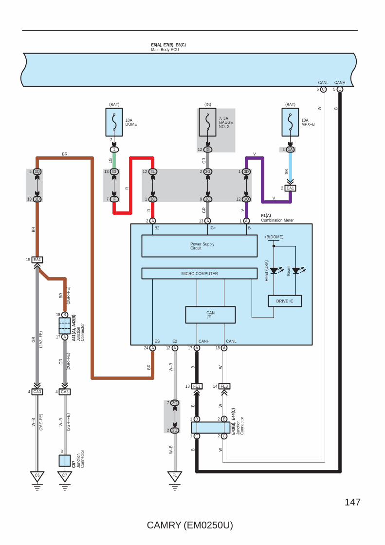
CAMRY (EM0250U)
147
B
WB
1 C 2 C
2 BB1
( 2G
R–F
E)
GR
W
E43(
B), E
44( C
)
E6(A), E7(B), E8(C)
BR
BR
15 EA1
( 2A
Z–FE
)( 2
AZ–
FE)
( 2G
R–F
E)
( 2G
R–F
E)
A41(
A), A
42( B
)
GR
W–B
W–B
3
C7
4 CA3
17 A
18 B
C6
4 CA3
10 3D
5 3Q
DRIVE IC
MICRO COMPUTER
B2 B
Bea
m
Hea
d ( U
SA
)
17 A A18A24
1
V
IG+
A
1 3D
12 3Q
10AMPX–B
(BAT)
2
R
R
LG
A
12 3L
1 3Q
13 ID
7 IF
1
10ADOME
(BAT)
2
Power SupplyCircuit
13
GR
GR
A
2 3G
9 3Q
12 IG
7. 5AGAUGENO. 2
(IG)
12 A
EA12
V
V
SB
3Q7
3U2
F1
W–B
W–BBR
ES CANH CANL
F1(A)
+B(DOME)
Junc
tion
Con
nect
or
Junc
tion
Con
nect
or
Main Body ECU
Combination Meter
E2
Junc
tion
Con
nect
or
C57
WB
C6 C5
CANL CANH
W B
BR
13 FE3 14 FE3
1A3
CANI/F

148
CAMRY (EM0250U)
Headlight
E6(A), E7(B), E8(C)
F1
12
10
E2
( Ped
al T
ype)
E33
IM2
1
Y L
1
14 IC
19
PKB
25ADOORNO. 1
2
1
(BAT)
ID16
W
ALTB
6
A18
(BAT)
2
BATB(∗1)
25ADOORNO. 2
W–B
IF10
GND1
5
( Lev
er T
ype)
W–B
2
E49
Par
king
Bra
ke S
W
Par
king
Bra
ke S
W
Junction Connector
Main Body ECU
10AECU–BNO. 1
2
1
ID10
26
BECU(∗2)
O
(BAT)
FE34
W–B
W–B
W O
∗ 1 : w/ Smart Key System∗ 2 : w/o Smart Key System
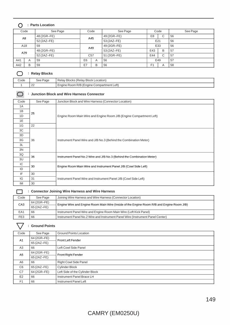
CAMRY (EM0250U)
149
: Parts Location
Code See Page Code See Page Code See Page
A848 (2GR–FE)
A4549 (2GR–FE) E8 C 56
A852 (2AZ–FE)
A4553 (2AZ–FE) E21 56
A18 59A49
49 (2GR–FE) E33 56
A2948 (2GR–FE)
A4953 (2AZ–FE) E43 B 57
A2952 (2AZ–FE) C57 51 (2GR–FE) E44 C 57
A41 A 59 E6 A 56 E49 57
A42 B 59 E7 B 56 F1 A 58
: Relay Blocks
Code See Page Relay Blocks (Relay Block Location)
1 22 Engine Room R/B (Engine Compartment Left)
: Junction Block and Wire Harness Connector
Code See Page Junction Block and Wire Harness (Connector Location)
1A
25Engine Room Main Wire and Engine Room J/B (Engine Compartment Left)
1B25
Engine Room Main Wire and Engine Room J/B (Engine Compartment Left)1D25
Engine Room Main Wire and Engine Room J/B (Engine Compartment Left)
1E
Engine Room Main Wire and Engine Room J/B (Engine Compartment Left)
1G 22
3C
36 Instrument Panel Wire and J/B No.3 (Behind the Combination Meter)
3D
36 Instrument Panel Wire and J/B No.3 (Behind the Combination Meter)3G 36 Instrument Panel Wire and J/B No.3 (Behind the Combination Meter)
3L
36 Instrument Panel Wire and J/B No.3 (Behind the Combination Meter)
3N
3Q36 Instrument Panel No.2 Wire and J/B No.3 (Behind the Combination Meter)
3U36 Instrument Panel No.2 Wire and J/B No.3 (Behind the Combination Meter)
IC30 Engine Room Main Wire and Instrument Panel J/B (Cowl Side Left)
ID30 Engine Room Main Wire and Instrument Panel J/B (Cowl Side Left)
IF 30
Instrument Panel Wire and Instrument Panel J/B (Cowl Side Left)IG 31 Instrument Panel Wire and Instrument Panel J/B (Cowl Side Left)
IM 30
Instrument Panel Wire and Instrument Panel J/B (Cowl Side Left)
: Connector Joining Wire Harness and Wire Harness
Code See Page Joining Wire Harness and Wire Harness (Connector Location)
CA364 (2GR–FE)
Engine Wire and Engine Room Main Wire (Inside of the Engine Room R/B and Engine Room J/B)CA365 (2AZ–FE)
Engine Wire and Engine Room Main Wire (Inside of the Engine Room R/B and Engine Room J/B)
EA1 66 Instrument Panel Wire and Engine Room Main Wire (Left Kick Panel)
FE3 66 Instrument Panel No.2 Wire and Instrument Panel Wire (Instrument Panel Center)
: Ground Points
Code See Page Ground Points Location
A164 (2GR–FE)
Front Left FenderA165 (2AZ–FE)
Front Left Fender
A3 66 Left Cowl Side Panel
A564 (2GR–FE)
Front Right FenderA565 (2AZ–FE)
Front Right Fender
A6 66 Right Cowl Side Panel
C6 65 (2AZ–FE) Cylinder Block
C7 64 (2GR–FE) Left Side of the Cylinder Block
E2 66 Instrument Panel Brace LH
F1 66 Instrument Panel Left
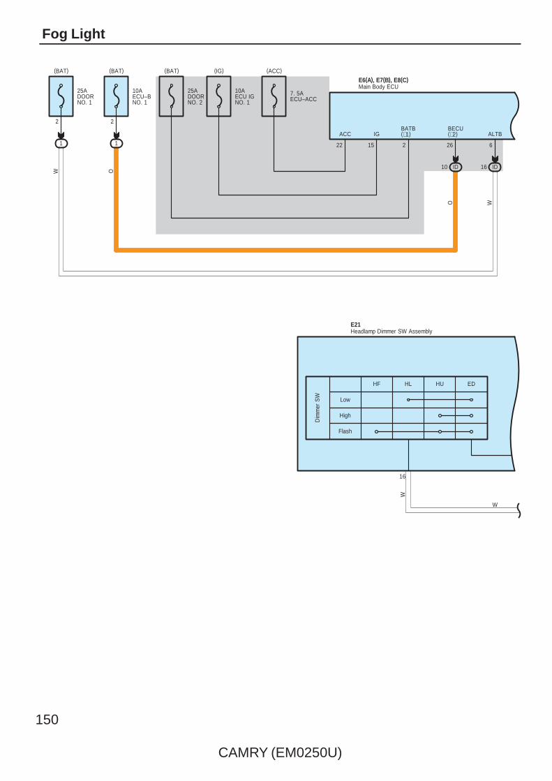
150
CAMRY (EM0250U)
Fog Light
(ACC)
7. 5AECU–ACC
15
IG
22
ACC
(BAT)
BECU(∗2)
26
10 ID
1
2
10AECU–BNO. 1
25ADOORNO. 1
2
1
(BAT)
ID16
W
ALTB
6
(BAT)
2
BATB(∗1)
25ADOORNO. 2
16
W
E6(A), E7(B), E8(C)Main Body ECU
Low
High
Flash
HF HL HU
Dim
mer
SW
ED
Headlamp Dimmer SW AssemblyE21
(IG)
10AECU IGNO. 1
OW
O
W

CAMRY (EM0250U)
151
12
E6(A), E7(B), E8(C)
20 4
A17 A28
4M5
4H6
VV
P
FFOGHEAD
IM9
E2
3G3
3C3
W
3
2
9
GND2
4
W–B
W–B
W–B
DRL–OFF(USA)OFF (ExceptUSA)
Main Body ECU
AUTO
Tail
Head
T H A
Ligh
t Con
trol S
W
Fog
SW
EL
BFGLFG
On
OFF
Junc
tion
Con
nect
or
E49
6
W–B
W–B
Headlamp Dimmer SW AssemblyE21
W
∗ 1 : w/ Smart Key System∗ 2 : w/o Smart Key System
3N9
3G12
P

152
CAMRY (EM0250U)
Fog Light
( 2G
R–F
E)
E6(A), E7(B), E8(C)
BR
GR
BR
BR
C57
15 EA1
( 2A
Z–FE
)( 2
AZ–
FE)
( 2G
R–F
E)
( 2G
R–F
E)
A41(
A), A
42( B
)
GR
W–B
W–B
3
C7
4 CA3
17 A
18 B
C6
4 CA3
10 3D
5 3Q
DRIVE IC
+B(DOME)
MICRO COMPUTER
B2 B
Fron
t Fog
17 A A18A24
1
V
IG+
A
1 3D
12 3Q
10AMPX–B
(BAT)
2
R
R
LG
A
12 3L
1 3Q
13 ID
7 IF
1
10ADOME
(BAT)
2
Power SupplyCircuit
13
GR
GR
A
2 3G
9 3Q
12 IG
7. 5AGAUGENO. 2
(IG)
12 A
EA12
SB
3Q7
3U2
F1
W–B
W–BBR
ES CANH CANL
Junc
tion
Con
nect
or
JunctionConnector
Main Body ECU
E2
WB
Combination MeterF1(A)
W
B
V
1A3
CANI/F

CAMRY (EM0250U)
153
B
W B
1 B2 B
BW
CANHCANL
5 C6 C
1 5
2 3
A5
15ATAIL
(BAT)
IL3
IL4
W
II8
FFGO
B
R
IC1ID5
1
2
1
2
R
W–B
Y
W–B
FOG
Rel
ay
A1 A34
3 2
4
5 1
IA1
IF10
R
TRLY
7
B
TAIL
Rel
ay
GND1
5
E6(A), E7(B), E8(C)
1
A2
4
( 2G
R–F
E ∗
1)
W–B
W
A2
( 2G
R–F
E ∗
2)
BR
A43
Fog
Lam
p( F
ront
LH
)
Fog
Lam
p( F
ront
RH
)
Junc
tion
Con
nect
or
Main Body ECU
C2 C1
Junc
tion
Con
nect
or
E43(
B), E
44( C
)
(BAT)
120AALT
1F1
E2F1
12
FE34
2
10JunctionConnector
E49
15AFR FOG
W–B
W–BW
–B
W–B
W
B
14 FE3 13 FE3
W–B
(2GR–FE ∗2)
( 2A
Z–FE
)
W–B
∗ 1 : w/ Smart Key System∗ 2 : w/o Smart Key System

154
CAMRY (EM0250U)
Fog Light
: Parts Location
Code See Page Code See Page Code See Page
A148 (2GR–FE) A43 49 (2GR–FE) E43 B 57
A152 (2AZ–FE) C57 51 (2GR–FE) E44 C 57
A3448 (2GR–FE) E6 A 56 E49 57
A3452 (2AZ–FE) E7 B 56 F1 A 58
A41 A 59 E8 C 56
A42 B 59 E21 56
: Relay Blocks
Code See Page Relay Blocks (Relay Block Location)
1 22 Engine Room R/B (Engine Compartment Left)
: Junction Block and Wire Harness Connector
Code See Page Junction Block and Wire Harness (Connector Location)
1A 25Engine Room Main Wire and Engine Room J/B (Engine Compartment Left)
1F 22Engine Room Main Wire and Engine Room J/B (Engine Compartment Left)
3C
36 Instrument Panel Wire and J/B No.3 (Behind the Combination Meter)
3D
36 Instrument Panel Wire and J/B No.3 (Behind the Combination Meter)3G 36 Instrument Panel Wire and J/B No.3 (Behind the Combination Meter)
3L
36 Instrument Panel Wire and J/B No.3 (Behind the Combination Meter)
3N
3Q36 Instrument Panel No.2 Wire and J/B No.3 (Behind the Combination Meter)
3U36 Instrument Panel No.2 Wire and J/B No.3 (Behind the Combination Meter)
4H42 Instrument Panel Wire and J/B No.4 (Instrument Panel Brace Center)
4M42 Instrument Panel Wire and J/B No.4 (Instrument Panel Brace Center)
IA
30 Engine Room Main Wire and Instrument Panel J/B (Cowl Side Left)IC 30 Engine Room Main Wire and Instrument Panel J/B (Cowl Side Left)
ID
30 Engine Room Main Wire and Instrument Panel J/B (Cowl Side Left)
IF 30
Instrument Panel Wire and Instrument Panel J/B (Cowl Side Left)
IG31
Instrument Panel Wire and Instrument Panel J/B (Cowl Side Left)II31
Instrument Panel Wire and Instrument Panel J/B (Cowl Side Left)
IL30
Instrument Panel Wire and Instrument Panel J/B (Cowl Side Left)
IM30
: Connector Joining Wire Harness and Wire Harness
Code See Page Joining Wire Harness and Wire Harness (Connector Location)
CA364 (2GR–FE)
Engine Wire and Engine Room Main Wire (Inside of the Engine Room R/B and Engine Room J/B)CA365 (2AZ–FE)
Engine Wire and Engine Room Main Wire (Inside of the Engine Room R/B and Engine Room J/B)
EA1 66 Instrument Panel Wire and Engine Room Main Wire (Left Kick Panel)
FE3 66 Instrument Panel No.2 Wire and Instrument Panel Wire (Instrument Panel Center)
: Ground Points
Code See Page Ground Points Location
A264 (2GR–FE)
Front Left FenderA265 (2AZ–FE)
Front Left Fender
A564 (2GR–FE)
Front Right FenderA565 (2AZ–FE)
Front Right Fender
C6 65 (2AZ–FE) Cylinder Block
C7 64 (2GR–FE) Left Side of the Cylinder Block
E2 66 Instrument Panel Brace LH
F1 66 Instrument Panel Left

CAMRY (EM0250U)
155
Memo

156
CAMRY (EM0250U)
Multiplex Communication System – CAN
CANH CANL
B
CANH CANL CANH CANL
CANH
CAN+ CAN–
CANL
CAN+ CAN–
CAN+
W
BB
( 2G
R–F
E)
Y
( 2G
R–F
E)
A25
15
A26(A), A60(B)
26
C56
35
E38(A)
1 2
E61
7 A A40(A), E41(B)1 A8 A2 A
8 B2 B 4 B 10 B7 B1 B
6
CAN–B
2 B
W
7
B1
W
( w/o
VS
C)
B
( w/o
VS
C)
B
( w/ V
SC
)
W
49 A
W
( w/ V
SC
)
B
41 A11 A
A11 A12
(∗3)B14(∗2)A25
Skid Control ECUwith Actuator
Skid Control ECUwith Actuator
Junction Connector
Transmission Control ECU
A/C AmplifierOption Connector(Bus Buffer)
B
W
CANH CANL
W
49 A
B
41 A
Eng
ine
Con
trol M
odul
eA5
5(A)
, C55
( B)
Eng
ine
Con
trol M
odul
eA2
4(A)
( 2A
Z–FE
)
( 2A
Z–FE
)
( 2G
R–F
E)
( 2G
R–F
E)

CAMRY (EM0250U)
157
B
W
F1(A)
CANHCANL
BB
CANL CANH
109
E17
WW
E30(A)
CANHCANL
CANL
W
14 6
E10
CANH
BB
CANH
E34(A), E65(B)
W
CANLB
B
W
1 B2 B1 H2 H
2 E E11 AA2
22 A
2 G G1
D2 D1
28 A
C15 C16
CANN
L
A
( ∗1)
( ∗1)
CANHCANL
27
C2
CANP
C1
BW
E58(A)
W
E42(
A), E
43( B
) , E4
4(C
) , E4
5(D
) , E4
6(E)
, E62
( G) ,
E63(
H)
A13 A18 A17
∗ 1 : w/ Smart Key System
Data Link Connector 3
Steering SensorAirbag SensorAssembly Center
Yaw Rate Sensor
Junc
tion
Con
nect
or
Certification ECU
Combination Meter
Mai
n B
ody
EC
UE8
( C)
C5 C6
CANH CANL
W
A2 (∗2)A3(∗3)B2B3
14 FE3 13 FE3
∗ 2 : TMC Made∗ 3 : TMMK Made

158
CAMRY (EM0250U)
Multiplex Communication System – CAN
CAN has two lines as a pair which make communication with operating voltage. CAN has excellent data speed and errordetecting capacity. It consists of vehicle control systems such as engine control module, yaw rate sensor, skid control ECUwith actuator, steering sensor, data link connector 3, A/C amplifier, transmission control ECU, airbag sensor assembly center,combination meter, certification ECU and main body ECU.
: Parts Location
Code See Page Code See Page Code See Page
A24 A 52 (2AZ–FE) C56 51 (2GR–FE) E44 C 57
A2548 (2GR–FE) E8 C 56 E45 D 57
A2552 (2AZ–FE) E10 56 E46 E 57
A26 A48 (2GR–FE) E17 56 E58 A 57
A26 A52 (2AZ–FE) E30 A 56 E61 57
A40 A 59 E34 A 57 E62 G 57
A55 A 49 (2GR–FE) E38 A 57 E63 H 57
A60 B49 (2GR–FE) E41 B 57 E65 B 57
A60 B53 (2AZ–FE) E42 A 57 F1 A 58
C55 B 51 (2GR–FE) E43 B 57
: Connector Joining Wire Harness and Wire Harness
Code See Page Joining Wire Harness and Wire Harness (Connector Location)
FE3 66 Instrument Panel No.2 Wire and Instrument Panel Wire (Instrument Panel Center)
System Outline

CAMRY (EM0250U)
159
Memo
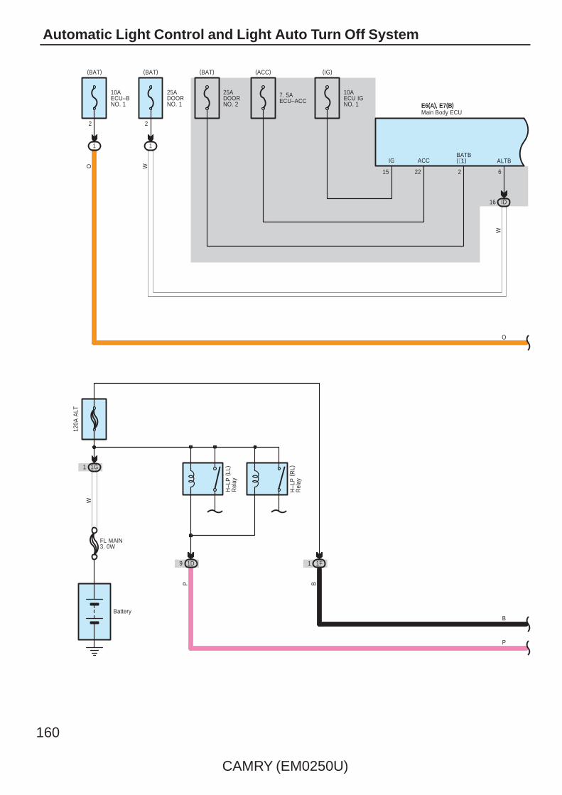
160
CAMRY (EM0250U)
Automatic Light Control and Light Auto Turn Off System
Battery
1G1
120A
ALT
W
H–L
P (
RL)
Rel
ay
H–L
P (
LL)
Rel
ay
(IG)(ACC)
7. 5AECU–ACC
15
IG
22
ACC
(BAT)
1
2
10AECU–BNO. 1 E6(A), E7(B)
Main Body ECU
10AECU IGNO. 1
(BAT)
2
BATB(∗1)
25ADOORNO. 2
P
P
O25ADOORNO. 1
2
1
(BAT)
ID16
W
6
W
O
ALTB
FL MAIN3. 0W
1F1
B
B
1D9
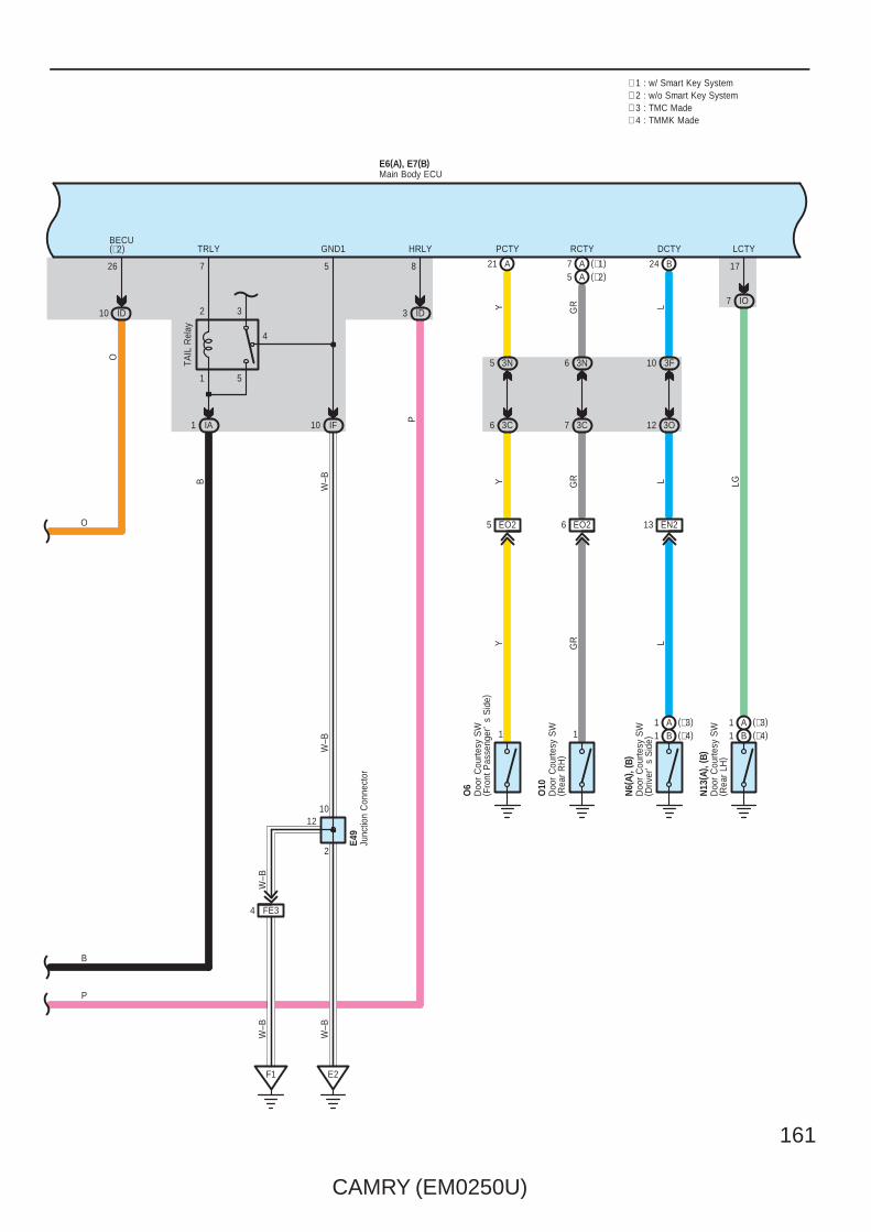
CAMRY (EM0250U)
161
HRLY
8
P
3 ID
O
BECU(∗2)
26
10 ID
F1 E2
W–B
2
∗ 1 : w/ Smart Key System
W–B
IA1 IF10
TRLY
7
TAIL
Rel
ay
GND1
5
FE34
W–B
W–B
Junc
tion
Con
nect
orE4
9
1012
P
O
∗ 2 : w/o Smart Key System
1 5
2 3
4
B
W–B
B
Main Body ECUE6(A), E7(B)
21
13
24
LCTY
17
EN2
N6(
A), (
B)
L
EO25
1
O6
Y
EO2
N13
( A) ,
( B)
6
1
O10
GR
3C7
3N6
L
DCTY
B
PCTY
A
RCTY
L
IO7
Y
LGGRY
7
3O12
3F10
3C6
GR
A
3N5
(∗1)(∗2)A5
Doo
r C
ourte
sy S
W( R
ear
LH)
Doo
r C
ourte
sy S
W( D
river
's
Sid
e)
Doo
r C
ourte
sy S
W( R
ear
RH
)
Doo
r C
ourte
sy S
W( F
ront
Pas
seng
er'
s S
ide)
∗ 3 : TMC Made∗ 4 : TMMK Made
(∗4)B1(∗3)A1
(∗4)B1(∗3)A1

162
CAMRY (EM0250U)
Automatic Light Control and Light Auto Turn Off System
12
E6(A), E7(B)
18 20 19
B23 B21
3N9
3G12
A17
G
P
B P
AHEADTAIL
IM9
E2
3G3
3C3
2
9
GND2
4
W–B
W–B
W–B
W–B
DRL–OFF(USA)OFF (ExceptUSA)
Main Body ECU
AUTO
Tail
Head
T H A
Ligh
t Con
trol S
W
EL
W–B 6
Headlamp Dimmer SW AssemblyE21
Junc
tion
Con
nect
or
E49
E11(A), (B)
CLTS
G
A
CLTS
CLTE
BR
A
CLTE
CLTB
B
A
CLTB
20 18 19
B3 B6 A
6A3
(∗6)B4(∗5)A5
Automatic LightControl Sensor
∗ 5 : Automatic A/C∗ 6 : Manual A/C
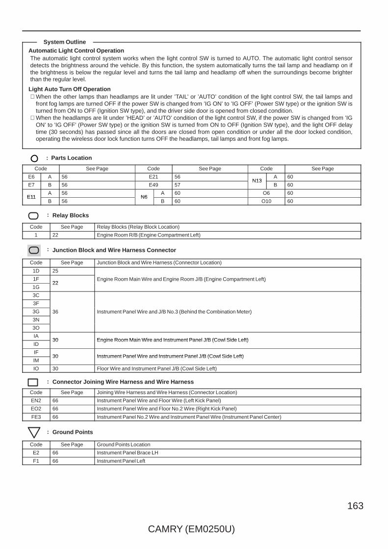
CAMRY (EM0250U)
163
Automatic Light Control OperationThe automatic light control system works when the light control SW is turned to AUTO. The automatic light control sensordetects the brightness around the vehicle. By this function, the system automatically turns the tail lamp and headlamp on ifthe brightness is below the regular level and turns the tail lamp and headlamp off when the surroundings become brighterthan the regular level.
Light Auto Turn Off Operation∗ When the other lamps than headlamps are lit under ’TAIL’ or ’AUTO’ condition of the light control SW, the tail lamps and
front fog lamps are turned OFF if the power SW is changed from ’IG ON’ to ’IG OFF’ (Power SW type) or the ignition SW isturned from ON to OFF (Ignition SW type), and the driver side door is opened from closed condition.
∗ When the headlamps are lit under ’HEAD’ or ’AUTO’ condition of the light control SW, if the power SW is changed from ’IGON’ to ’IG OFF’ (Power SW type) or the ignition SW is turned from ON to OFF (Ignition SW type), and the light OFF delaytime (30 seconds) has passed since all the doors are closed from open condition or under all the door locked condition,operating the wireless door lock function turns OFF the headlamps, tail lamps and front fog lamps.
: Parts Location
Code See Page Code See Page Code See Page
E6 A 56 E21 56N13
A 60
E7 B 56 E49 57N13
B 60
E11A 56
N6A 60 O6 60
E11B 56
N6B 60 O10 60
: Relay Blocks
Code See Page Relay Blocks (Relay Block Location)
1 22 Engine Room R/B (Engine Compartment Left)
: Junction Block and Wire Harness Connector
Code See Page Junction Block and Wire Harness (Connector Location)
1D 25
Engine Room Main Wire and Engine Room J/B (Engine Compartment Left)1F22
Engine Room Main Wire and Engine Room J/B (Engine Compartment Left)
1G22
Engine Room Main Wire and Engine Room J/B (Engine Compartment Left)
3C
36 Instrument Panel Wire and J/B No.3 (Behind the Combination Meter)
3F
36 Instrument Panel Wire and J/B No.3 (Behind the Combination Meter)3G 36 Instrument Panel Wire and J/B No.3 (Behind the Combination Meter)
3N
36 Instrument Panel Wire and J/B No.3 (Behind the Combination Meter)
3O
IA30 Engine Room Main Wire and Instrument Panel J/B (Cowl Side Left)
ID30 Engine Room Main Wire and Instrument Panel J/B (Cowl Side Left)
IF30 Instrument Panel Wire and Instrument Panel J/B (Cowl Side Left)
IM30 Instrument Panel Wire and Instrument Panel J/B (Cowl Side Left)
IO 30 Floor Wire and Instrument Panel J/B (Cowl Side Left)
: Connector Joining Wire Harness and Wire Harness
Code See Page Joining Wire Harness and Wire Harness (Connector Location)
EN2 66 Instrument Panel Wire and Floor Wire (Left Kick Panel)
EO2 66 Instrument Panel Wire and Floor No.2 Wire (Right Kick Panel)
FE3 66 Instrument Panel No.2 Wire and Instrument Panel Wire (Instrument Panel Center)
: Ground Points
Code See Page Ground Points Location
E2 66 Instrument Panel Brace LH
F1 66 Instrument Panel Left
System Outline

164
CAMRY (EM0250U)
Interior Light
(IG) (ACC)
7. 5AECU–ACC
15
IG
22
ACC
10AECU IGNO. 1
25ADOORNO. 1
2
1
(BAT) (BAT)
2
BATB(∗1)
25ADOORNO. 2
E6(A), E7(B)Main Body ECU
W
∗ 2 : w/o Smart Key System∗ 1 : w/ Smart Key System
∗ 3 : TMC Made∗ 4 : TMMK Made
ID10
BECU(∗2)
26
10AECU–BNO. 1
1
2
(BAT)
O
O
W
∗ 5 : w/ Sliding Roof

CAMRY (EM0250U)
165
O
21
13
24
4 3I3I7
L
EN2
N6(
A), (
B)
L
EO25
1
O6
Y
EO26
1
O10
GR
3C7
3N6
L
DCTY
B
PCTY
A
RCTY
L Y
GR YGR
OB
7
3F113O12
3F10
Y1
2
3C6
E2
1
2
GR
1
2
A
E5 E37
( ∗5)
( ∗5)
3N5
(∗1)(∗2)A5
Dio
de (
Doo
rC
ourte
sy R
ear
RH
)
Dio
de (
Doo
rC
ourte
sy F
ront
RH
)
Dio
de (
Doo
rC
ourte
sy F
ront
LH
)
Doo
r C
ourte
sy S
W( D
river
's
Sid
e)
Doo
r C
ourte
sy S
W( R
ear
RH
)
Doo
r C
ourte
sy S
W( F
ront
Pas
seng
er'
s S
ide)
E1( ∗
5)
LCTY
17
N13
( A) ,
( B)
IO7
LG LG
IL6
( ∗5)
1
2
L
Dio
de (
Doo
rC
ourte
sy R
ear
LH)
Doo
r C
ourte
sy S
W( R
ear
LH)
ID16
W
ALTB
6
Main Body ECUE6(A), E7(B)Main Body ECU
O
O
B(∗5)
L(∗5)
(∗4)B1(∗3)A1
(∗4)B1(∗3)A1
W

166
CAMRY (EM0250U)
Interior Light
W
1
3 SN1
W
2
W
A
S5
2
EN217
3
WLGCY
15
9
1
25
E
BR(∗2)
W
W
W
B
1
W
2
Q1 E
B
W
1
2Q
2
EQ116
18 EQ1
IR5 II10
BR
W
10ADOME
2
1
W
LG
W–B
(BAT)
+B
ILE
21
14
( ∗6)
W
13
N28
W
S15
B
N23
(∗5)
( ∗5)
( ∗5)
(∗5)
( ∗5)
Dio
de (
Lugg
age
Com
partm
ent L
amp)
Junc
tion
Con
nect
or
Van
ity L
amp
SW
(LH
)
Van
ity L
amp
SW
(R
H)
Junc
tion
Con
nect
or
Doo
r Lo
ck A
ssem
bly
( Lug
gage
)
Van
ity L
amp
( LH
)
Q7
Van
ity L
amp
( RH
)
Q8
S1
IM9
E2
2
6
GND2
4
W–B
W–B
Junc
tion
Con
nect
or
E49
Main Body ECUE6(A), E7(B)Main Body ECU
O
O
B(∗5)
L(∗5)
W–B
W–B
W–B
∗ 6 : w/o Sliding Roof∗ 5 : w/ Sliding Roof∗ 2 : w/o Smart Key System
O
O
B(∗5)
L(∗5)
W(∗6)
LG
V(∗5)
V ( ∗5)
2 2
1 1
W–B
W
(∗5)

CAMRY (EM0250U)
167
WW
W
W ( ∗5)R
W
( ∗5)
W–B
( ∗5)
W–B
( ∗6)
W
( ∗6)
W( ∗
6)
( ∗6) W
W
( ∗6)
B ( ∗5)W
( ∗5)
L
(∗5)
W
(∗5)
B
( ∗5)
B B B
W
Q10
19 EQ1
6
17 EQ1
8
W
BR(∗2)
W
11 EQ1
8
( ∗5)
( ∗5)
( ∗5)
LEE
4
L
3
Q11EECTY
7
32
7 1 2 2
Q6
5
Q6
4
(∗5)
Map
Lam
p ( R
H)
Map
Lam
p ( L
H)
Ove
rhea
d J/
B
Ove
rhea
d J/
B
OFF
ON
DO
OR
Main Body ECUE6(A), E7(B)Main Body ECU
L(∗5)
W–B
B
O
O
W–B(∗5)
LG
W–B
R(∗5)
BR(∗2)
W
O
O
B(∗5)
W(∗6)
Roo
m L
amp
( Cen
ter)
Q9
V(∗5)
V( ∗
5)
Map Lamp Map Lamp
LG
W
(∗5)
WW
B

168
CAMRY (EM0250U)
Interior Light
LG
( ∗5)
( ∗5)
O( ∗2)
IF7
EQ17
IL10
2
6
3G11
1
2
2 IE2
IE23
OR
RR
3I12
1
2
2 HE2
HE23
OO
RR
RR
R
WW
6 IR
15 EQ1
17
20R
B
ID13 10 IP
R
I6 H7
N24
( A) ,
N26
( B)
E25
1R
N15
N28
3B12
18
R
BR
ILL+
ILL–
3L12
Igni
tion
Key
Cyl
inde
rLi
ght
( ∗2)
(∗2)B2(∗1)A2
(∗1)A1(∗2)B1
Tran
spon
der
Key
Am
plifi
er
Cou
rtesy
Lam
p( F
ront
Doo
r R
H)
Cou
rtesy
Lam
p( F
ront
Doo
r LH
)
Noi
se F
ilter
( Dom
e an
d S
top)
Lugg
age
Com
partm
ent
Lam
pJu
nctio
nC
onne
ctor
E6(A), E7(B)Main Body ECUMain Body ECU
B
O
O
W–B(∗5)
LG
W–B W–B
R(∗5)
BR(∗2)
W
∗ 2 : w/o Smart Key System∗ 5 : w/ Sliding Roof
∗ 1 : w/ Smart Key System∗ 2 : w/o Smart Key System∗ 1 : w/ Smart Key System
W–B(∗5)
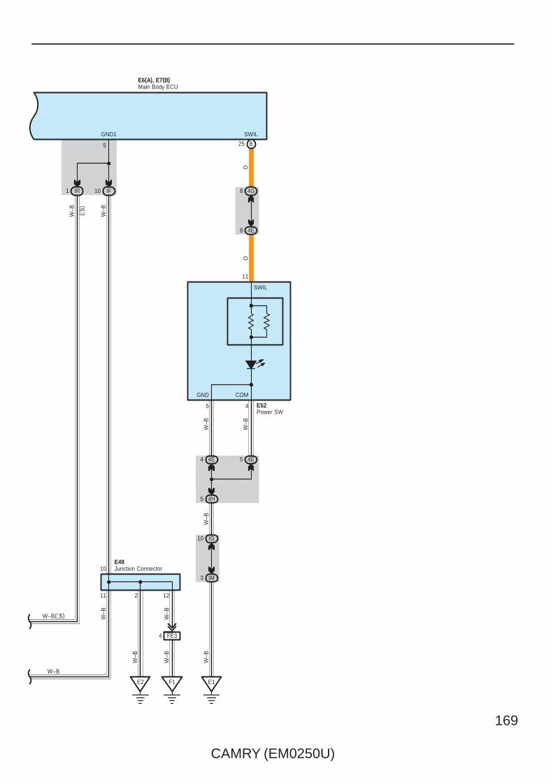
CAMRY (EM0250U)
169
F1
11
E2
W–B
IF10
W–B
IR1
GND1
5
12
W–B
2
( ∗5)
FE34
10
5 4H
W–B
W–B
O
SWIL
4E54E4
45
COMGND
SWIL
11
25 B
E1
W–B
W–B
3 IM
10 IG
4G8
4E8
O
E52Power SW
Junction ConnectorE49
E6(A), E7(B)Main Body ECU
W–B(∗5)
W–B
W–B
W–B
W–B
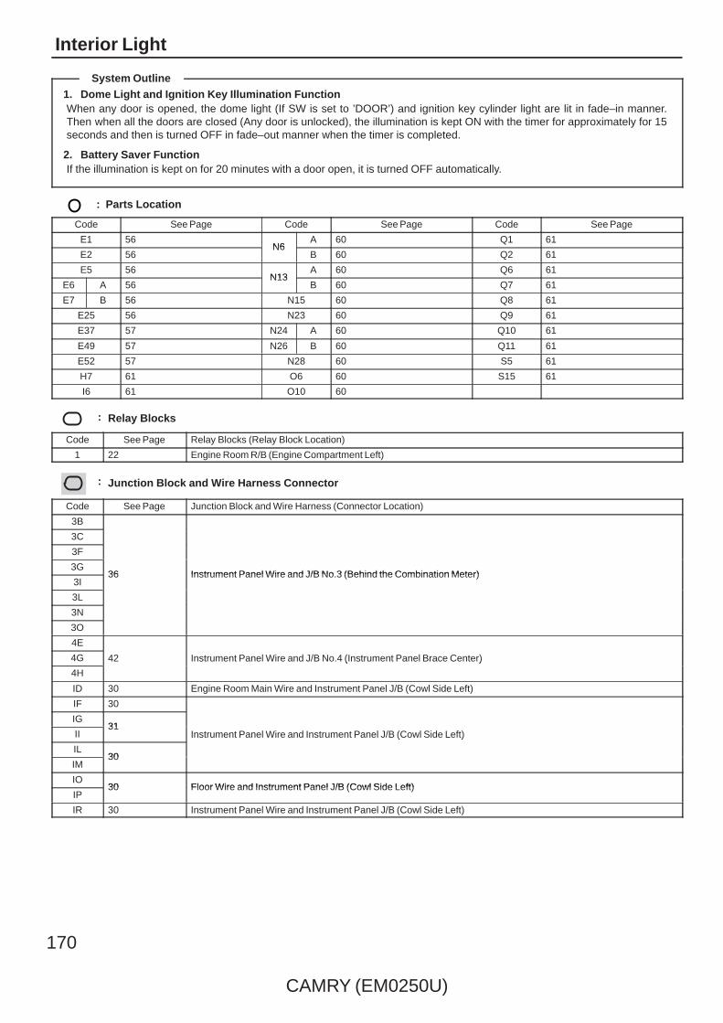
170
CAMRY (EM0250U)
Interior Light
1. Dome Light and Ignition Key Illumination FunctionWhen any door is opened, the dome light (If SW is set to ’DOOR’) and ignition key cylinder light are lit in fade–in manner.Then when all the doors are closed (Any door is unlocked), the illumination is kept ON with the timer for approximately for 15seconds and then is turned OFF in fade–out manner when the timer is completed.
2. Battery Saver FunctionIf the illumination is kept on for 20 minutes with a door open, it is turned OFF automatically.
: Parts Location
Code See Page Code See Page Code See Page
E1 56N6
A 60 Q1 61
E2 56N6
B 60 Q2 61
E5 56N13
A 60 Q6 61
E6 A 56N13
B 60 Q7 61
E7 B 56 N15 60 Q8 61
E25 56 N23 60 Q9 61
E37 57 N24 A 60 Q10 61
E49 57 N26 B 60 Q11 61
E52 57 N28 60 S5 61
H7 61 O6 60 S15 61
I6 61 O10 60
: Relay Blocks
Code See Page Relay Blocks (Relay Block Location)
1 22 Engine Room R/B (Engine Compartment Left)
: Junction Block and Wire Harness Connector
Code See Page Junction Block and Wire Harness (Connector Location)
3B
36 Instrument Panel Wire and J/B No.3 (Behind the Combination Meter)
3C
36 Instrument Panel Wire and J/B No.3 (Behind the Combination Meter)
3F
36 Instrument Panel Wire and J/B No.3 (Behind the Combination Meter)3G
36 Instrument Panel Wire and J/B No.3 (Behind the Combination Meter)3I
36 Instrument Panel Wire and J/B No.3 (Behind the Combination Meter)
3L
3N
3O
4E
42 Instrument Panel Wire and J/B No.4 (Instrument Panel Brace Center)4G 42 Instrument Panel Wire and J/B No.4 (Instrument Panel Brace Center)
4H
42 Instrument Panel Wire and J/B No.4 (Instrument Panel Brace Center)
ID 30 Engine Room Main Wire and Instrument Panel J/B (Cowl Side Left)
IF 30
Instrument Panel Wire and Instrument Panel J/B (Cowl Side Left)
IG31
Instrument Panel Wire and Instrument Panel J/B (Cowl Side Left)II31
Instrument Panel Wire and Instrument Panel J/B (Cowl Side Left)
IL30
Instrument Panel Wire and Instrument Panel J/B (Cowl Side Left)
IM30
IO30 Floor Wire and Instrument Panel J/B (Cowl Side Left)
IP30 Floor Wire and Instrument Panel J/B (Cowl Side Left)
IR 30 Instrument Panel Wire and Instrument Panel J/B (Cowl Side Left)
System Outline
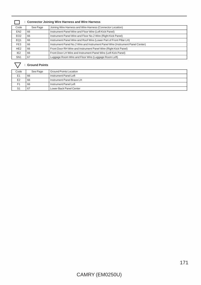
CAMRY (EM0250U)
171
: Connector Joining Wire Harness and Wire Harness
Code See Page Joining Wire Harness and Wire Harness (Connector Location)
EN2 66 Instrument Panel Wire and Floor Wire (Left Kick Panel)
EO2 66 Instrument Panel Wire and Floor No.2 Wire (Right Kick Panel)
EQ1 66 Instrument Panel Wire and Roof Wire (Lower Part of Front Pillar LH)
FE3 66 Instrument Panel No.2 Wire and Instrument Panel Wire (Instrument Panel Center)
HE2 66 Front Door RH Wire and Instrument Panel Wire (Right Kick Panel)
IE2 66 Front Door LH Wire and Instrument Panel Wire (Left Kick Panel)
SN1 67 Luggage Room Wire and Floor Wire (Luggage Room Left)
: Ground Points
Code See Page Ground Points Location
E1 66 Instrument Panel Left
E2 66 Instrument Panel Brace LH
F1 66 Instrument Panel Left
S1 67 Lower Back Panel Center

172
CAMRY (EM0250U)
Taillight and Illumination
( 2G
R–F
E)
(BAT)
1
2
10AECU–BNO. 1
GR
25ADOORNO. 1
2
1
(BAT)
BR
BR
C57
15 EA1
( 2A
Z–FE
)( 2
AZ–
FE)
( 2G
R–F
E)
( 2G
R–F
E)
A41(
A), A
42( B
)
GR
W–B
W–B
3
C7
4 CA3
17 A
18 B
C6
4 CA3
5 3Q
10 3D
DRIVE IC
MICRO COMPUTER
B2 B
Tail
( Exc
ept U
SA
)
17 A A18A24
1V
IG+
A
1 3D
12 3Q
1A
10AMPX–B
(BAT)
2
RLG
A
12 3L
1 3Q
13 ID
7 IF
1
10ADOME
(BAT)
2
Power SupplyCircuit
13
GR
GR
A
2 3G
9 3Q
12 IG
7. 5AGAUGENO. 2
(IG)
EA12
SB
BR
ES CANH CANL
+B(DOME)
Junc
tion
Con
nect
or
JunctionConnector
VCombination MeterF1(A)
W
B
O
W
R
BR
3
RheostatTail Cancel SW
CANI/F
B W
W O
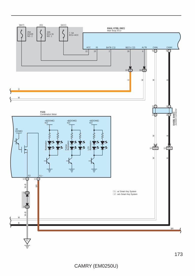
CAMRY (EM0250U)
173
B
W B
1 B2 B
BW
CANHCANL
5 C6 C
(IG) (ACC)
7. 5AECU–ACC
15
IG
22
ACC BECU (∗2)
26
10 ID ID16
W
ALTB
6
(BAT)
2
BATB (∗1)
25ADOORNO. 2
W
E43(
B), E
44( C
)
E6(A), E7(B), E8(C)
A11
ILL–
BR
+B(DOME)IG2
+B(DOME)IG2
+B(DOME)IG2
12 A
LCD
Illum
inat
ion
Poi
nter
Illum
inat
ion
Illum
inat
ion
3Q7
3U2
F1
W–B
W–B
E2
F1(A)
+B(DOME)
Junc
tion
Con
nect
or
Main Body ECU
Combination Meter
C2 C1
10AECU IGNO. 1
W
B
O
W
BR
∗ 1 : w/ Smart Key System∗ 2 : w/o Smart Key System
FE314 FE313
O

174
CAMRY (EM0250U)
Taillight and Illumination
F1 E2
W–B
IF10
TRLY
7
O
ACAN
A
3O2
GND1
5
3R12
O
16
12
E6(A), E7(B), E8(C)
18
B23
B
TAIL
IM9
3G3
3C3
GND2
4
W–B
W–B
W–B
W–B
2
DRL–OFF(USA)OFF (ExceptUSA)
Main Body ECU
AUTO
Tail
Head
T H A
Ligh
t Con
trol S
W
EL
3R8
3U2
F1
GND1
ILL+
19
4
Clo
ckF3
FE34
W–B
10
Hea
dlam
p D
imm
er S
W A
ssem
bly
E21
W–B
W–B
W–B
BR BR
Junc
tion
Con
nect
orE4
9
129
6
W–B
W–B
W–B
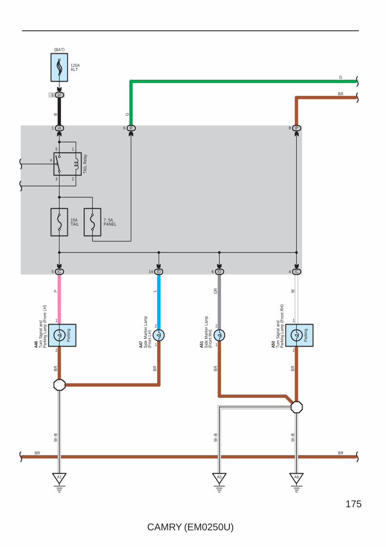
CAMRY (EM0250U)
175
A1
BR
W–B
L
14 ID
1
2
A47
15ATAIL
3 2
4
5 1
IA1
B
TAIL
Rel
ay
W
G
7. 5APANEL
IF6 IP8
A46
1
2 2
1
A50
IC5 IC4
PB
R
BR
G
W–B
A5
W–B
A6
BR
6 ID
A51
2
1
GR
Turn
Sig
nal a
ndP
arki
ng L
amp
( Fro
nt L
H)
Sid
e M
arke
r La
mp
( Fro
nt L
H)
Turn
Sig
nal a
ndP
arki
ng L
amp
( Fro
nt R
H)
Sid
e M
arke
r La
mp
( Fro
nt R
H)
1F1
(BAT)
BR
BR BR
Par
king
Par
king
120AALT

176
CAMRY (EM0250U)
Taillight and Illumination
S12
22 20
SN1
S4
S2
2
1
2
1
2
1
Tail
W–B
BR
BR
BR
BR
BR
BR
6
S15
S1
W–B
W–B
W–B
1
BR
9
1
2
19
Tail
33
Stop Lamp SW
7
G G
W–B
S11
17
16 21
S16
18
S1
BR
S3
BR
W–B
W–B
W–B
9
W–B W–B
Lice
nse
Pla
teLa
mp
( RH
)
Rea
r C
ombi
natio
nLa
mp
( LH
)
Rea
r C
ombi
natio
nLa
mp
( RH
)
Junction Connector
Junction Connector
Rea
r C
ombi
natio
n La
mp
( RH
)
Rea
r C
ombi
natio
nLa
mp
( LH
)
Lice
nse
Pla
teLa
mp
( LH
)
BR
3 3
1 1
BRBR
L L
Tail
Sto
p
Sto
p
Tail
Sid
e M
arke
r
Sid
e M
arke
r
BR

CAMRY (EM0250U)
177
F6( A
) , F7
( B) ,
F8( C
) , F2
6(D
)
ILL–
8
4
ILL+
3T
BR
4D
5 4B
W–B
LGB
R
3L4
3B4
3B9
4
E31
BR
3C4
3C9
E55
2
1
BR
F9( E
) , F1
0(F)
7
G
5 3S
BR
3S11
ILL–
GB
R
7 3R
3R4
7
8
F4 F16
11
ILL+SWG
3T5
G
ILL–
ILL+
P
11
4B9
4D8
G
3Q4
G
3A1
3T1
Tran
smis
sion
Con
trol S
W
Sea
t Hea
ter
SW
A/C
Con
trol A
ssem
bly
Haz
ard
War
ning
Sig
nal S
W
Rad
io R
ecei
ver
Ass
embl
y
Nav
igat
ion
Rec
eive
r A
ssem
bly
BR
G
P
∗ 3 : 8 Speaker w/ Navigation System∗ 4 : 8 Speaker w/o Navigation System
SG
8
3A9
3S12
R ( ∗5)
R
(∗5)
∗ 5 : Automatic A/C∗ 6 : 6 Speaker
(∗6)C6(∗4)C6(∗3)F6
A10D2E2
(∗3)E12(∗4)D12(∗6)B5
A/T Shift LeverIllumination

178
CAMRY (EM0250U)
Taillight and Illumination
W–B
F1
4 3A
a1(B)
EAU IL+2
1
2
F5
4 3T
W–B
Ste
erin
g S
W R
H
Ste
erin
g S
W L
H
2 3U
2 3T
Steering Pad SW
Glo
ve B
ox L
amp
B8 B5
B R
A4 A12
P LGS
eek
DIS
PV
oice
AU
TO/O
FF
TEM
P
TEL
Vol
ume
MO
DE
BR
Spiral CableE18(A), a1(B)
P
(∗7)
EAC
9 A
GR
2 B
( ∗5)
R
(∗5)
R ( ∗5)
∗ 5 : Automatic A/C∗ 7 : Manual A/C
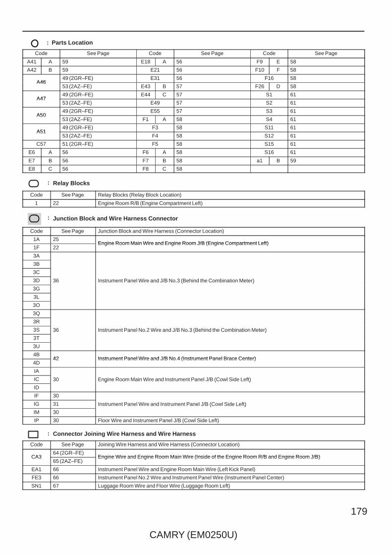
CAMRY (EM0250U)
179
: Parts Location
Code See Page Code See Page Code See Page
A41 A 59 E18 A 56 F9 E 58
A42 B 59 E21 56 F10 F 58
A4649 (2GR–FE) E31 56 F16 58
A4653 (2AZ–FE) E43 B 57 F26 D 58
A4749 (2GR–FE) E44 C 57 S1 61
A4753 (2AZ–FE) E49 57 S2 61
A5049 (2GR–FE) E55 57 S3 61
A5053 (2AZ–FE) F1 A 58 S4 61
A5149 (2GR–FE) F3 58 S11 61
A5153 (2AZ–FE) F4 58 S12 61
C57 51 (2GR–FE) F5 58 S15 61
E6 A 56 F6 A 58 S16 61
E7 B 56 F7 B 58 a1 B 59
E8 C 56 F8 C 58
: Relay Blocks
Code See Page Relay Blocks (Relay Block Location)
1 22 Engine Room R/B (Engine Compartment Left)
: Junction Block and Wire Harness Connector
Code See Page Junction Block and Wire Harness (Connector Location)
1A 25Engine Room Main Wire and Engine Room J/B (Engine Compartment Left)
1F 22Engine Room Main Wire and Engine Room J/B (Engine Compartment Left)
3A
36 Instrument Panel Wire and J/B No.3 (Behind the Combination Meter)
3B
36 Instrument Panel Wire and J/B No.3 (Behind the Combination Meter)
3C
36 Instrument Panel Wire and J/B No.3 (Behind the Combination Meter)3D 36 Instrument Panel Wire and J/B No.3 (Behind the Combination Meter)
3G
36 Instrument Panel Wire and J/B No.3 (Behind the Combination Meter)
3L
3O
3Q
36 Instrument Panel No.2 Wire and J/B No.3 (Behind the Combination Meter)
3R
36 Instrument Panel No.2 Wire and J/B No.3 (Behind the Combination Meter)3S 36 Instrument Panel No.2 Wire and J/B No.3 (Behind the Combination Meter)
3T
36 Instrument Panel No.2 Wire and J/B No.3 (Behind the Combination Meter)
3U
4B42 Instrument Panel Wire and J/B No.4 (Instrument Panel Brace Center)
4D42 Instrument Panel Wire and J/B No.4 (Instrument Panel Brace Center)
IA
30 Engine Room Main Wire and Instrument Panel J/B (Cowl Side Left)IC 30 Engine Room Main Wire and Instrument Panel J/B (Cowl Side Left)
ID
30 Engine Room Main Wire and Instrument Panel J/B (Cowl Side Left)
IF 30
Instrument Panel Wire and Instrument Panel J/B (Cowl Side Left)IG 31 Instrument Panel Wire and Instrument Panel J/B (Cowl Side Left)
IM 30
Instrument Panel Wire and Instrument Panel J/B (Cowl Side Left)
IP 30 Floor Wire and Instrument Panel J/B (Cowl Side Left)
: Connector Joining Wire Harness and Wire Harness
Code See Page Joining Wire Harness and Wire Harness (Connector Location)
CA364 (2GR–FE)
Engine Wire and Engine Room Main Wire (Inside of the Engine Room R/B and Engine Room J/B)CA365 (2AZ–FE)
Engine Wire and Engine Room Main Wire (Inside of the Engine Room R/B and Engine Room J/B)
EA1 66 Instrument Panel Wire and Engine Room Main Wire (Left Kick Panel)
FE3 66 Instrument Panel No.2 Wire and Instrument Panel Wire (Instrument Panel Center)
SN1 67 Luggage Room Wire and Floor Wire (Luggage Room Left)
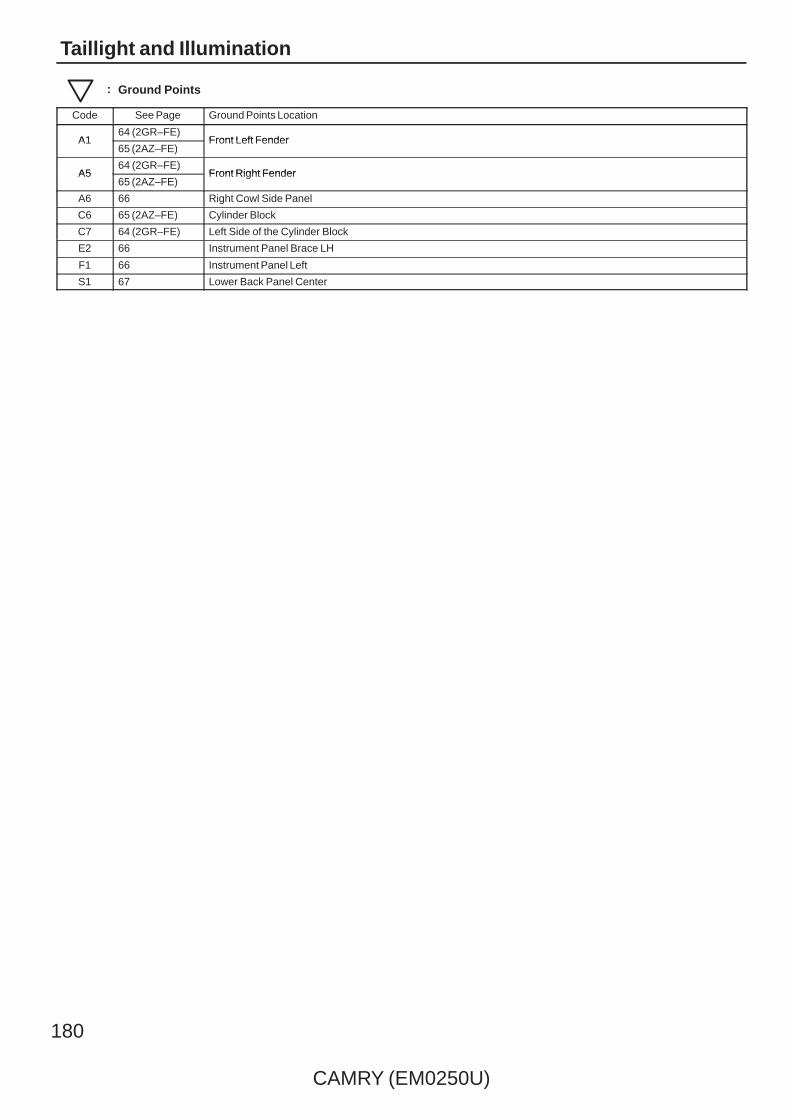
180
CAMRY (EM0250U)
Taillight and Illumination
: Ground Points
Code See Page Ground Points Location
A164 (2GR–FE)
Front Left FenderA165 (2AZ–FE)
Front Left Fender
A564 (2GR–FE)
Front Right FenderA565 (2AZ–FE)
Front Right Fender
A6 66 Right Cowl Side Panel
C6 65 (2AZ–FE) Cylinder Block
C7 64 (2GR–FE) Left Side of the Cylinder Block
E2 66 Instrument Panel Brace LH
F1 66 Instrument Panel Left
S1 67 Lower Back Panel Center

CAMRY (EM0250U)
181
Memo

182
CAMRY (EM0250U)
Turn Signal and Hazard Warning Light
Y
Y
IF
2
10AGAUGENO. 1
R
B
3
3L
9 IL
1 II
W–B
23
S1
S15
GG
12 IP
6 II
Y
G
2
7 ID
(BAT)
IC3
(IG)
G
15AHAZ
1
W–B
A1
W–B
14
3
2
3
2
EN14
R
Y
2
W–B
Turn
Turn
A46
A50
A6
3F1
9 EA1
10 SN1
W–B
9
SN111B
R
BR
G
Turn
Sig
nal a
ndP
arki
ng L
amp
( Fro
nt L
H)
Turn
Sig
nal a
ndP
arki
ng L
amp
( Fro
nt R
H)
Junc
tion
Con
nect
or
LL
41
2
11
2 Turn
Sig
nal L
amp
( Rea
r R
H)
S13
Turn
Sig
nal L
amp
( Rea
r LH
)
S10
LRBIG
Turn Signal FlasherE14
G

CAMRY (EM0250U)
183
19
20
E
WW
–BW
–BW
3R8
3U2
F1
HAZ
5
4
3F9
3R3
F47
W–B
W–B
8 IG IG2
B GTu
rn R
H
Turn
LH
L G
E49
2
W–B
B B
A12
12F3
TR EL TL
1513
LH
12
RH
Turn
SW
GND1
3F3
W–B
LG
W–B
3G3
3G8
3P5
3F7
3P7
8
Clock
Haz
ard
War
ning
Sig
nal S
W
B B
E2ES
A247 3Q
W–B
W–B
GR
BR
A41(
A), A
42( B
)
C57
( ∗1)
( ∗1)
( ∗2)
(∗1)
3Q5
3D10
CA34
C6
15EA1
BR GR(∗2)
A17
B18
CA34
BR(∗1)
C7
GR
3
Junc
tion
Con
nect
or
Junc
tion
Con
nect
or
W–B
9
E2
W–B
3 3C
JunctionConnector
ELERE
6 5
O L
Hea
dlam
p D
imm
erS
W A
ssem
bly
E21
∗ 1 : 2GR–FE∗ 2 : 2AZ–FE
Com
bina
tion
Met
erF1
( A) ,
F2( B
)Turn Signal FlasherE14

184
CAMRY (EM0250U)
Turn Signal and Hazard Warning Light
: Parts Location
Code See Page Code See Page Code See Page
A41 A 59 C57 51 (2GR–FE) F3 58
A42 B 59 E14 56 F4 58
A4649 (2GR–FE) E21 56 S10 61
A4653 (2AZ–FE) E49 57 S13 61
A5049 (2GR–FE) F1 A 58 S15 61
A5053 (2AZ–FE) F2 B 58
: Relay Blocks
Code See Page Relay Blocks (Relay Block Location)
1 22 Engine Room R/B (Engine Compartment Left)
: Junction Block and Wire Harness Connector
Code See Page Junction Block and Wire Harness (Connector Location)
3C
36 Instrument Panel Wire and J/B No.3 (Behind the Combination Meter)
3D
36 Instrument Panel Wire and J/B No.3 (Behind the Combination Meter)3F 36 Instrument Panel Wire and J/B No.3 (Behind the Combination Meter)
3G
36 Instrument Panel Wire and J/B No.3 (Behind the Combination Meter)
3L
3P
36 Instrument Panel No.2 Wire and J/B No.3 (Behind the Combination Meter)3Q
36 Instrument Panel No.2 Wire and J/B No.3 (Behind the Combination Meter)3R
36 Instrument Panel No.2 Wire and J/B No.3 (Behind the Combination Meter)
3U
IC30 Engine Room Main Wire and Instrument Panel J/B (Cowl Side Left)
ID30 Engine Room Main Wire and Instrument Panel J/B (Cowl Side Left)
IF 30
Instrument Panel Wire and Instrument Panel J/B (Cowl Side Left)IG
31 Instrument Panel Wire and Instrument Panel J/B (Cowl Side Left)II
31 Instrument Panel Wire and Instrument Panel J/B (Cowl Side Left)
IL 30
IP 30 Floor Wire and Instrument Panel J/B (Cowl Side Left)
: Connector Joining Wire Harness and Wire Harness
Code See Page Joining Wire Harness and Wire Harness (Connector Location)
CA364 (2GR–FE)
Engine Wire and Engine Room Main Wire (Inside of the Engine Room R/B and Engine Room J/B)CA365 (2AZ–FE)
Engine Wire and Engine Room Main Wire (Inside of the Engine Room R/B and Engine Room J/B)
EA1 66 Instrument Panel Wire and Engine Room Main Wire (Left Kick Panel)
EN1 66 Instrument Panel Wire and Floor Wire (Left Kick Panel)
SN1 67 Luggage Room Wire and Floor Wire (Luggage Room Left)
: Ground Points
Code See Page Ground Points Location
A164 (2GR–FE)
Front Left FenderA165 (2AZ–FE)
Front Left Fender
A6 66 Right Cowl Side Panel
C6 65 (2AZ–FE) Cylinder Block
C7 64 (2GR–FE) Left Side of the Cylinder Block
E2 66 Instrument Panel Brace LH
F1 66 Instrument Panel Left
S1 67 Lower Back Panel Center
CAMRY (EM0250U)
185
Memo

186
CAMRY (EM0250U)
Stop Light
N15
2
L
10ASTOP
IC8
(BAT)
L L L
N1
5
W–B
8
7
9
8
W–B
W–B
S1
9
7
W–B
SN18
IP3
6
IL7
AE29
10
10
9
L
B
L
L L
N28
N16
11 1
23 2
N29
Noi
se F
ilter
( Dom
e an
d S
top)
Cen
ter
Sto
p La
mp
Junc
tion
Con
nect
or
JunctionConnector
Sto
p La
mp
SW
A19
Rea
r C
ombi
natio
n La
mp
( RH
)S1
2
2 3
TAIL Fuse
Junction ConnectorS16
JunctionConnector
S15
Rea
r C
ombi
natio
nLa
mp
( LH
)
S11
BR
BR
Tail
Sto
p
Sto
p
Tail
2
1
BW W
SN11 W–BW–B

CAMRY (EM0250U)
187
: Parts Location
Code See Page Code See Page Code See Page
A19 59 N28 60 S12 61
N15 60 N29 60 S15 61
N16 60 S11 61 S16 61
: Junction Block and Wire Harness Connector
Code See Page Junction Block and Wire Harness (Connector Location)
IC 30 Engine Room Main Wire and Instrument Panel J/B (Cowl Side Left)
IL 30 Instrument Panel Wire and Instrument Panel J/B (Cowl Side Left)
IP 30 Floor Wire and Instrument Panel J/B (Cowl Side Left)
: Connector Joining Wire Harness and Wire Harness
Code See Page Joining Wire Harness and Wire Harness (Connector Location)
AE2 66 Engine Room Main Wire and Instrument Panel Wire (Right Side of the Instrument Panel J/B)
SN1 67 Luggage Room Wire and Floor Wire (Luggage Room Left)
: Ground Points
Code See Page Ground Points Location
N1 67 Left Rear Quarter Panel
S1 67 Lower Back Panel Center

188
CAMRY (EM0250U)
Back–Up Light
R
W–B
R
W–B
2
W–B
W–B
RR
( M/T
)
R
L
R
GR
RR
( M/T
)
L
L
( M/T
)
B
(A/T)
O
R
(A/T)
R
P
C28
( A/T
)
C1(
A), (
B)
E48
S16
S2S3
S15
Bac
k–U
p
4
3
Bac
k–U
p
4
3
10AGAUGENO. 1
IH16
S1
1
9
1
3
17 SN1
RB
EN1
3
9
2 A (2GR–FE)1 B (2AZ–FE)
2
R
RL
B
(IG)
20 CA2
2
6 AE3
2
1
A
10 CA2
1
R( ∗1)
( ∗1)
( ∗1)
(∗2)
∗ 2 : w/o Mirror Heater∗ 1 : w/ Mirror Heater
Par
k/N
eutra
lP
ositi
on S
W
Bac
k–U
p La
mp
SW
Junc
tion
Con
nect
or
Junc
tion
Con
nect
orJu
nctio
nC
onne
ctor
Rea
r C
ombi
natio
nLa
mp
( RH
)
Rea
r C
ombi
natio
nLa
mp
( LH
)
EA114
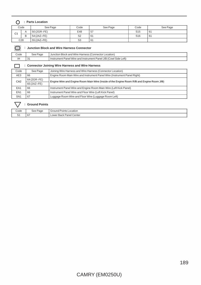
CAMRY (EM0250U)
189
: Parts Location
Code See Page Code See Page Code See Page
C1A 50 (2GR–FE) E48 57 S15 61
C1B 54 (2AZ–FE) S2 61 S16 61
C28 55 (2AZ–FE) S3 61
: Junction Block and Wire Harness Connector
Code See Page Junction Block and Wire Harness (Connector Location)
IH 31 Instrument Panel Wire and Instrument Panel J/B (Cowl Side Left)
: Connector Joining Wire Harness and Wire Harness
Code See Page Joining Wire Harness and Wire Harness (Connector Location)
AE3 66 Engine Room Main Wire and Instrument Panel Wire (Instrument Panel Right)
CA264 (2GR–FE)
Engine Wire and Engine Room Main Wire (Inside of the Engine Room R/B and Engine Room J/B)CA265 (2AZ–FE)
Engine Wire and Engine Room Main Wire (Inside of the Engine Room R/B and Engine Room J/B)
EA1 66 Instrument Panel Wire and Engine Room Main Wire (Left Kick Panel)
EN1 66 Instrument Panel Wire and Floor Wire (Left Kick Panel)
SN1 67 Luggage Room Wire and Floor Wire (Luggage Room Left)
: Ground Points
Code See Page Ground Points Location
S1 67 Lower Back Panel Center

190
CAMRY (EM0250U)
Key Reminder without Smart Key System and Seat Belt Warning
G
10 3R
10 3Q
GR
9 3R
9 A
MICRO COMPUTER
B2 B
17 A A18
Buzzer
A24
1
V
IG+
A
1 3D
12 3Q
10AMPX–B
(BAT)
2
RLG
A
12 3L
1 3Q
13 ID
7 IF
1
10ADOME
(BAT)
2
Power SupplyCircuit
13
GR
GR
A
2 3G
9 3Q
12 IG
7. 5AGAUGENO. 2
(IG)
12 A
EA12
SB
3Q7
3U2
F1
W–B
W–B
P/SB
BR
ES CANH CANL
G
( ∗1)
BR
GR
BR
BR
C57
15 EA1
( ∗2)
( ∗2)
( ∗1)
( ∗1)
A41(
A), A
42( B
)
GR
W–B
W–B
3
C7
4 CA3
17 A
18 B
C6
4 CA3
10 3D
5 3Q
Junc
tion
Con
nect
or
JunctionConnector
R
V
W
B
Clo
ckF3
IG PBEW
103
B W
E2
Com
bina
tion
Met
erF1
( A) ,
F2( B
)
Front PassengerSeat BeltWarning Light
13 FE3 14 FE3
1A3
CANI/F
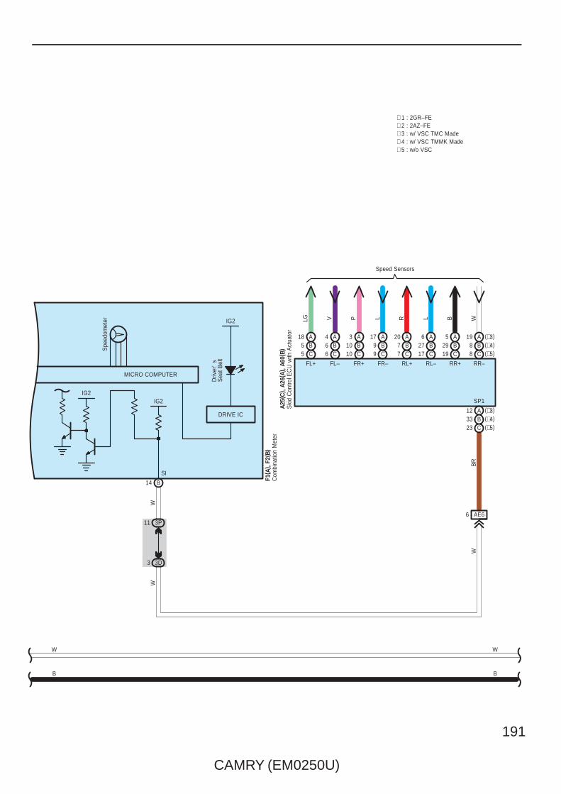
CAMRY (EM0250U)
191
DRIVE IC
IG2
Driv
er'
sS
eat B
elt
W
B
∗ 1 : 2GR–FE∗ 2 : 2AZ–FE
B
W
F1( A
) , F2
( B)
Com
bina
tion
Met
er
8 C (∗5)(∗4)B8(∗3)A19
C19B29A5
C17B27A6
C7B7A20
C9B9A17
C10B10A3
C6B6A4
C5B5A18
Speed Sensors
LG V P L R L B W
(∗3)A12(∗4)B33(∗5)C23
FL+ FL– FR+ FR– RL+ RL– RR+ RR–
SP1IG2
14 B
SI
3P11
3D3
AE66
WW
BR
W
Ski
d C
ontro
l EC
U w
ith A
ctua
tor
A25(
C) ,
A26(
A), A
60( B
)
MICRO COMPUTER
∗ 3 : w/ VSC TMC Made∗ 4 : w/ VSC TMMK Made∗ 5 : w/o VSC
IG2
Spe
edom
eter
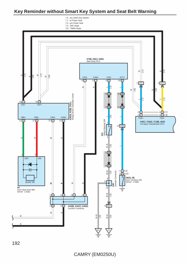
192
CAMRY (EM0250U)
Key Reminder without Smart Key System and Seat Belt Warning
4
FSP+
C
FSP–
C
8
B
L
LBE+
C
FSR+ FSR–
CDBE–
BB
DBE+
LBE–
N3
1 3
RG
1211
13 12
( ∗7)
( ∗7)Y
W
A8 A4
B
Front Seat Inner Belt(Driver' s Side)
B
1 B2 B
W
D2 D1
A22 A13
CANL CANH
3A2
2
1
3J5
3A7L
LW
–B
E22
D
KSW
3 3C
F1
12
9
W–B
E2
5
( ∗6)
( ∗6)
( ∗6)
( ∗6)
W–B
Unl
ock
War
ning
SW
FE34
W–B
W–B
C6 C5
CANL CANH
BW
Airb
ag S
enso
r A
ssem
bly
Cen
ter
E30(
A), N
1(B)
, O1(
C)
Main Body ECUE7(B), E8(C), E9(D)
Junc
tion
Con
nect
orE4
9
C2 C1
Junction ConnectorE43(B), E44(C), E45(D)
BWBWW B
W B
∗ 6 : w/o Smart Key System
( ∗6)
( ∗6)
( ∗6)
B W
BW
W
∗ 7 : w/ Power Seat∗ 8 : w/o Power Seat
( ∗8)( ∗
7)
( ∗8)( ∗
7)
( ∗7)
( ∗7)
( ∗8)
( ∗8)
B
W
(∗7)(∗8)
Occupant Classification ECUO4(C), T10(A), T11(B), d1(D)
Buckle SW
∗ 9 : TMC Made∗10 : TMMK Made
2
B24
DCTY
3F10
3O12
EN213
Door Courtesy SW(Driver' s Side)
N6(A), (B)
LL
L
(∗10)B1(∗9)A1
OT11 OT14
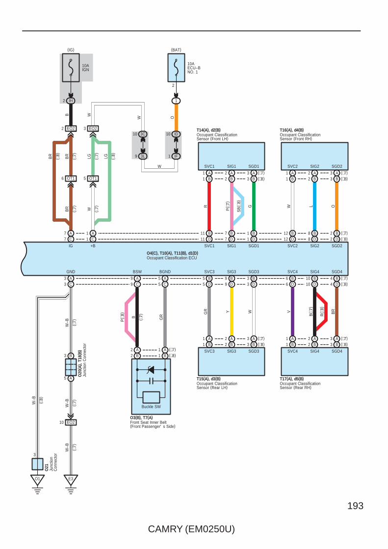
CAMRY (EM0250U)
193
BGND
A1
BSW
A2 (∗7)(∗8)
A99 C
P( ∗
8)
5 C5 A
( ∗7)B GR
O3(B), T7(A)
B1B2
Front Seat Inner Belt(Front Passenger' s Side)
B
SVC2SGD1
B
T17(A), d5(B)
B
DD
SVC4
D
SIG1SVC1
D
B( ∗
7)
R
P( ∗
7)
G OLW
SVC3 SIG3 SGD3
SIG4
SVC1
BR
B
SIG3
B
SGD3
B
SGD4
SIG2
D
SGD2
D
SVC3
SIG1 SGD1 SVC2 SIG2 SGD2
SVC4 SIG4 SGD4
T15(A), d3(B)
T14(A), d2(B) T16(A), d4(B)
VWYGR
11 7 1 12 8 2
5 9 3 6 10 4
Occupant ClassificationSensor (Front LH)
Occupant ClassificationSensor (Rear LH)
Occupant ClassificationSensor (Front RH)
Occupant ClassificationSensor (Rear RH)
(∗7)B2
(∗7)A3(∗8)B3
(∗7)A3(∗8)B3
A1B1
A2B2
A1
SB
( ∗8)
B1A2B2
B8B12B1B7B11(∗8)
D5 D9 D3 D6 D10 (∗8)D4
R( ∗
8)
B1 B2 (∗8)B3 B1 B2A2
(∗8)B3(∗7)A3A1 A2 (∗7)A3 A1
(∗7)
Occupant Classification ECUO4(C), T10(A), T11(B), d1(D)
( ∗8)
1
EO22
7 C
LG
10AECU–BNO. 1
10AIGN
W
9 3L
10 3C
( ∗7)
( ∗7)
( ∗7)
( ∗7)
LGBR
WBR
OW
1 IF
10 ID
2
1
(BAT)
2 IH
(IG)
3 EO2
+B
C
IG
A7 A1
( ∗8)
BR
B W
GND
( ∗7)
( ∗7)
W–B
5 A
3 C
W–B
3
( ∗8)
3 A
B
W–B
O1
3
O20
( A) ,
T18(
B)Ju
nctio
n C
onne
ctor
Junc
tion
Con
nect
or
O21
Buckle SW
OT16 OT15
EO210
E3
( ∗7)
W–B
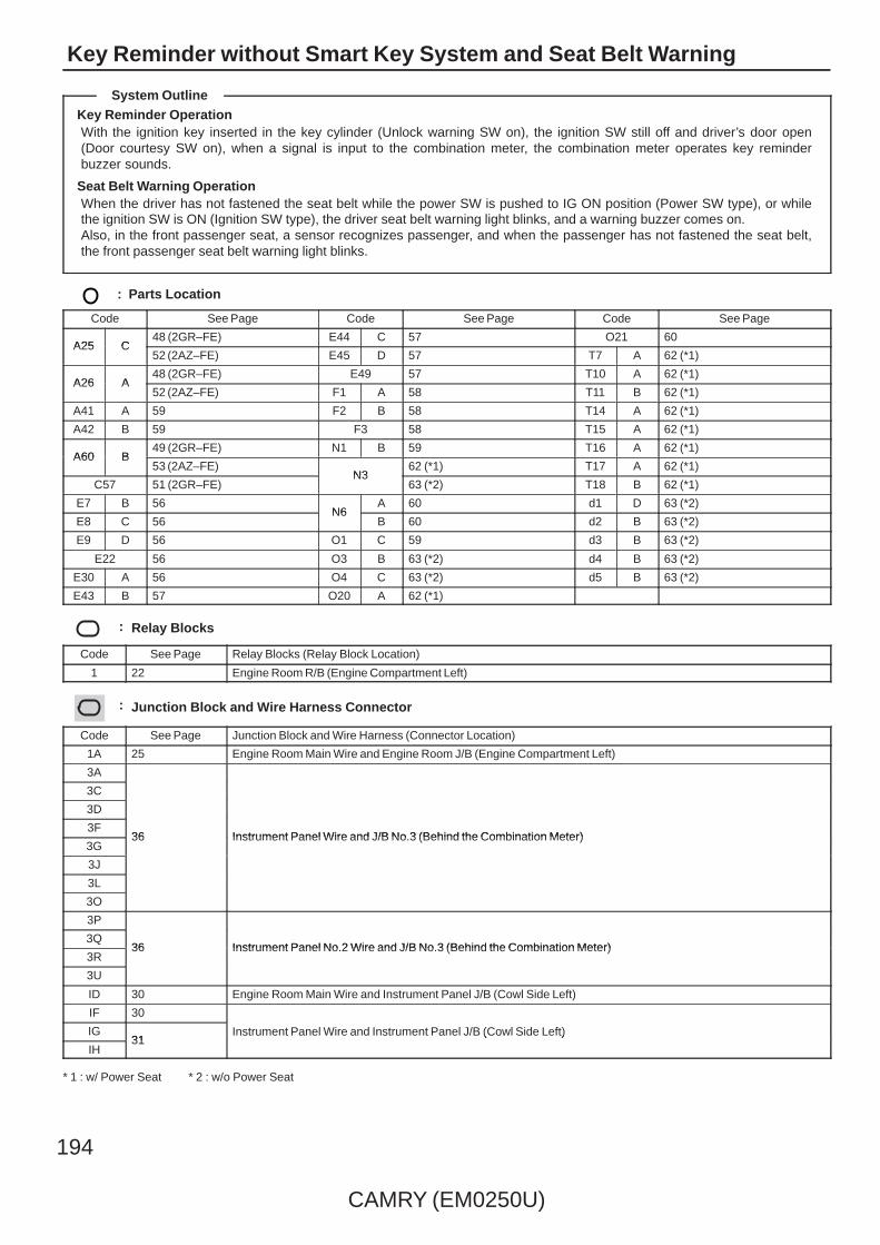
194
CAMRY (EM0250U)
Key Reminder without Smart Key System and Seat Belt Warning
Key Reminder OperationWith the ignition key inserted in the key cylinder (Unlock warning SW on), the ignition SW still off and driver’s door open(Door courtesy SW on), when a signal is input to the combination meter, the combination meter operates key reminderbuzzer sounds.
Seat Belt Warning OperationWhen the driver has not fastened the seat belt while the power SW is pushed to IG ON position (Power SW type), or whilethe ignition SW is ON (Ignition SW type), the driver seat belt warning light blinks, and a warning buzzer comes on.Also, in the front passenger seat, a sensor recognizes passenger, and when the passenger has not fastened the seat belt,the front passenger seat belt warning light blinks.
: Parts Location
Code See Page Code See Page Code See Page
A25 C48 (2GR–FE) E44 C 57 O21 60
A25 C52 (2AZ–FE) E45 D 57 T7 A 62 (*1)
A26 A48 (2GR–FE) E49 57 T10 A 62 (*1)
A26 A52 (2AZ–FE) F1 A 58 T11 B 62 (*1)
A41 A 59 F2 B 58 T14 A 62 (*1)
A42 B 59 F3 58 T15 A 62 (*1)
A60 B49 (2GR–FE) N1 B 59 T16 A 62 (*1)
A60 B53 (2AZ–FE)
N362 (*1) T17 A 62 (*1)
C57 51 (2GR–FE)N3
63 (*2) T18 B 62 (*1)
E7 B 56N6
A 60 d1 D 63 (*2)
E8 C 56N6
B 60 d2 B 63 (*2)
E9 D 56 O1 C 59 d3 B 63 (*2)
E22 56 O3 B 63 (*2) d4 B 63 (*2)
E30 A 56 O4 C 63 (*2) d5 B 63 (*2)
E43 B 57 O20 A 62 (*1)
: Relay Blocks
Code See Page Relay Blocks (Relay Block Location)
1 22 Engine Room R/B (Engine Compartment Left)
: Junction Block and Wire Harness Connector
Code See Page Junction Block and Wire Harness (Connector Location)
1A 25 Engine Room Main Wire and Engine Room J/B (Engine Compartment Left)
3A
36 Instrument Panel Wire and J/B No.3 (Behind the Combination Meter)
3C
36 Instrument Panel Wire and J/B No.3 (Behind the Combination Meter)
3D
36 Instrument Panel Wire and J/B No.3 (Behind the Combination Meter)3F
36 Instrument Panel Wire and J/B No.3 (Behind the Combination Meter)3G
36 Instrument Panel Wire and J/B No.3 (Behind the Combination Meter)
3J
3L
3O
3P
36 Instrument Panel No.2 Wire and J/B No.3 (Behind the Combination Meter)3Q
36 Instrument Panel No.2 Wire and J/B No.3 (Behind the Combination Meter)3R
36 Instrument Panel No.2 Wire and J/B No.3 (Behind the Combination Meter)
3U
ID 30 Engine Room Main Wire and Instrument Panel J/B (Cowl Side Left)
IF 30
Instrument Panel Wire and Instrument Panel J/B (Cowl Side Left)IG31
Instrument Panel Wire and Instrument Panel J/B (Cowl Side Left)
IH31
Instrument Panel Wire and Instrument Panel J/B (Cowl Side Left)
* 1 : w/ Power Seat * 2 : w/o Power Seat
System Outline

CAMRY (EM0250U)
195
: Connector Joining Wire Harness and Wire Harness
Code See Page Joining Wire Harness and Wire Harness (Connector Location)
AE6 66 Engine Room Main Wire and Instrument Panel Wire (Instrument Panel Right)
CA364 (2GR–FE)
Engine Wire and Engine Room Main Wire (Inside of the Engine Room R/B and Engine Room J/B)CA365 (2AZ–FE)
Engine Wire and Engine Room Main Wire (Inside of the Engine Room R/B and Engine Room J/B)
EA1 66 Instrument Panel Wire and Engine Room Main Wire (Left Kick Panel)
EN2 66 Instrument Panel Wire and Floor Wire (Left Kick Panel)
EO2 66 Instrument Panel Wire and Floor No.2 Wire (Right Kick Panel)
FE3 66 Instrument Panel No.2 Wire and Instrument Panel Wire (Instrument Panel Center)
OT1 68 (*1) Floor No.2 Wire and Front Seat RH Wire (Under the Front Passenger’s Seat)
: Ground Points
Code See Page Ground Points Location
C6 65 (2AZ–FE) Cylinder Block
C7 64 (2GR–FE) Left Side of the Cylinder Block
E2 66 Instrument Panel Brace LH
E3 66 Instrument Panel Right
F1 66 Instrument Panel Left
O1 67 Right Rear Quarter Panel
* 1 : w/ Power Seat * 2 : w/o Power Seat

196
CAMRY (EM0250U)
Wiper and Washer
B1
LO
3A
Wiper Relay
MIS
T
OFF INT
3
2A
1B
B
2B
4B
HI
EW
WF
+S
+1
+B
+2
INT1
INT2
+S+1
+2+B
Front Wiper SW
EW
On
Off
W
FrontWasher SW
E19(A), E20(B)Windshield Wiper SW Assembly
GR
W–B
W
P
G
L
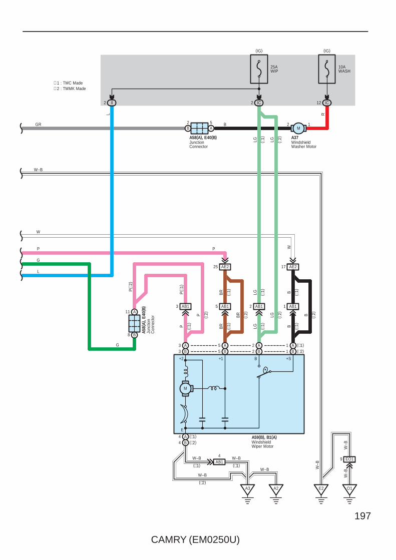
CAMRY (EM0250U)
197
IC12
12M
10AWASH
2
(IG)
IC
A3
2 II
AE21725 AE2
E2
M
+1+2
E
+SB
25AWIP
(IG)
B
L
LG
GR
W–B
W
P
G
L
P
BR
LG B
W–B
W
A37
A59(B), B1(A)
B2
A5
A11
B8
AB13
P( ∗
1)
AB15 AB12 AB11
A58(A), E40(B)A5
8(A)
, E40
( B)
BR
LG B
AB14W–B
WindshieldWasher Motor
JunctionConnector
Junc
tion
Con
nect
or
WindshieldWiper Motor
R
(∗2)B1B2B5B3A3 A5 A2 (∗1)A1
(∗1)A4(∗2)B4
( ∗1)
( ∗1)
( ∗1)
( ∗1)
( ∗1)
( ∗1)
( ∗1)
( ∗1)
P ( ∗2)
( ∗2)
BR
LG ( ∗2)
( ∗2)B
( ∗2)
LG
∗ 1 : TMC Made∗ 2 : TMMK Made
W–B
W–B
(∗1)
(∗2)
(∗1)
P
P( ∗
2)
G
A2 O1
EO19
W–B
W–B
W–B

198
CAMRY (EM0250U)
Wiper and Washer
: Parts Location
Code See Page Code See Page Code See Page
A3748 (2GR–FE) A59 B 53 (2AZ–FE) E20 B 56
A3752 (2AZ–FE)
B1 A49 (2GR–FE) E40 B 57
A58 A 59B1 A
53 (2AZ–FE)
A59 B 49 (2GR–FE) E19 A 56
: Junction Block and Wire Harness Connector
Code See Page Junction Block and Wire Harness (Connector Location)
IC 30 Engine Room Main Wire and Instrument Panel J/B (Cowl Side Left)
II 31 Instrument Panel Wire and Instrument Panel J/B (Cowl Side Left)
: Connector Joining Wire Harness and Wire Harness
Code See Page Joining Wire Harness and Wire Harness (Connector Location)
AB164 (2GR–FE)
Engine Room Main Wire and Engine Room No.2 Wire (Near the Windshield Wiper Motor)AB165 (2AZ–FE)
Engine Room Main Wire and Engine Room No.2 Wire (Near the Windshield Wiper Motor)
AE2 66 Engine Room Main Wire and Instrument Panel Wire (Right Side of the Instrument Panel J/B)
: Ground Points
Code See Page Ground Points Location
A264 (2GR–FE)
Front Left FenderA265 (2AZ–FE)
Front Left Fender
A3 66 Left Cowl Side Panel
E2 66 Instrument Panel Brace LH
O1 67 Right Rear Quarter Panel

CAMRY (EM0250U)
199
Memo
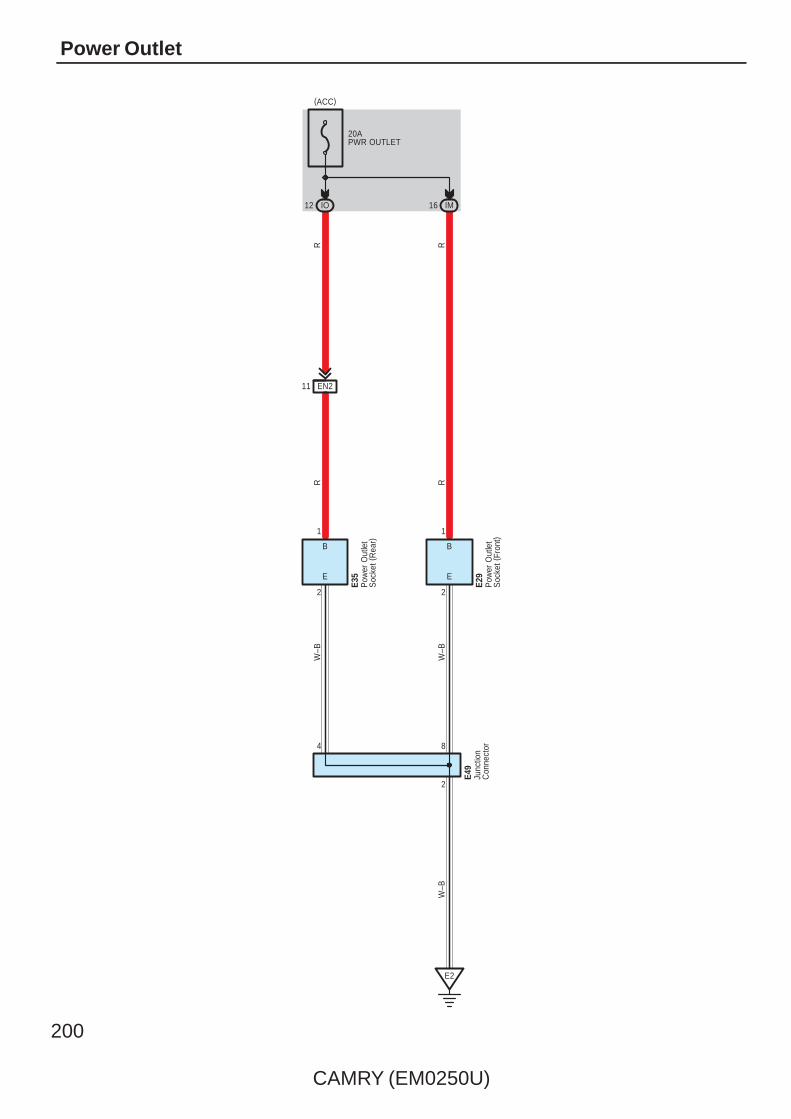
200
CAMRY (EM0250U)
Power Outlet
20APWR OUTLET
IO12
(ACC)
IM16
2
8
E2
4
EN211
R R
R R
W–B
W–B
W–B
2 2
1 1
E E
B B
E35
E29
E49
Pow
er O
utle
tS
ocke
t (Fr
ont)
Pow
er O
utle
tS
ocke
t (R
ear)
Junc
tion
Con
nect
or

CAMRY (EM0250U)
201
: Parts Location
Code See Page Code See Page Code See Page
E29 56 E35 57 E49 57
: Junction Block and Wire Harness Connector
Code See Page Junction Block and Wire Harness (Connector Location)
IM 30 Instrument Panel Wire and Instrument Panel J/B (Cowl Side Left)
IO 30 Floor Wire and Instrument Panel J/B (Cowl Side Left)
: Connector Joining Wire Harness and Wire Harness
Code See Page Joining Wire Harness and Wire Harness (Connector Location)
EN2 66 Instrument Panel Wire and Floor Wire (Left Kick Panel)
: Ground Points
Code See Page Ground Points Location
E2 66 Instrument Panel Brace LH
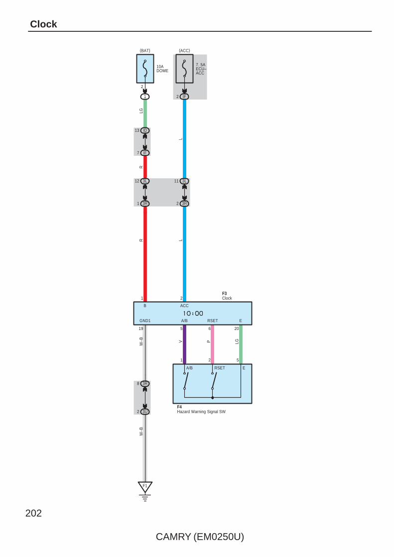
202
CAMRY (EM0250U)
Clock
1
V
2
P LG
5
206
F4
5
ERSETA/BGND1
ACCB
10ADOME
2
1
(BAT)
ID13
IF7
3L12
3R1
3L11
3R2
7. 5AECU–ACC
(ACC)
IF2
1 2
3R8
3U2
F1
W–B
19
LG
LLR
W–B
R
Hazard Warning Signal SW
ClockF3
A/B RSET E
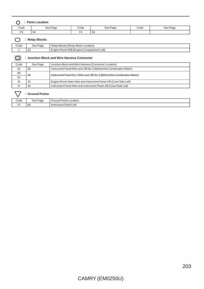
CAMRY (EM0250U)
203
: Parts Location
Code See Page Code See Page Code See Page
F3 58 F4 58
: Relay Blocks
Code See Page Relay Blocks (Relay Block Location)
1 22 Engine Room R/B (Engine Compartment Left)
: Junction Block and Wire Harness Connector
Code See Page Junction Block and Wire Harness (Connector Location)
3L 36 Instrument Panel Wire and J/B No.3 (Behind the Combination Meter)
3R36 Instrument Panel No.2 Wire and J/B No.3 (Behind the Combination Meter)
3U36 Instrument Panel No.2 Wire and J/B No.3 (Behind the Combination Meter)
ID 30 Engine Room Main Wire and Instrument Panel J/B (Cowl Side Left)
IF 30 Instrument Panel Wire and Instrument Panel J/B (Cowl Side Left)
: Ground Points
Code See Page Ground Points Location
F1 66 Instrument Panel Left

204
CAMRY (EM0250U)
Horn
Battery
10AHORN
10 1D 1B6
II5
ID11
W
A411
A3
BB
GR
HORNRelay
1G1
W
W
Horn (High)Horn (Low)
A8
HO
B1
LH
orn
SW
SteeringPad SW
a1(B)
Spiral CableE18(A), a1(B)
FL MAIN3. 0W

CAMRY (EM0250U)
205
: Parts Location
Code See Page Code See Page Code See Page
A348 (2GR–FE)
A448 (2GR–FE) E18 A 56
A352 (2AZ–FE)
A452 (2AZ–FE) a1 B 59
: Junction Block and Wire Harness Connector
Code See Page Junction Block and Wire Harness (Connector Location)
1B25
Engine Room Main Wire and Engine Room J/B (Engine Compartment Left)1D25
Engine Room Main Wire and Engine Room J/B (Engine Compartment Left)
1G 22
Engine Room Main Wire and Engine Room J/B (Engine Compartment Left)
ID 30 Engine Room Main Wire and Instrument Panel J/B (Cowl Side Left)
II 31 Instrument Panel Wire and Instrument Panel J/B (Cowl Side Left)
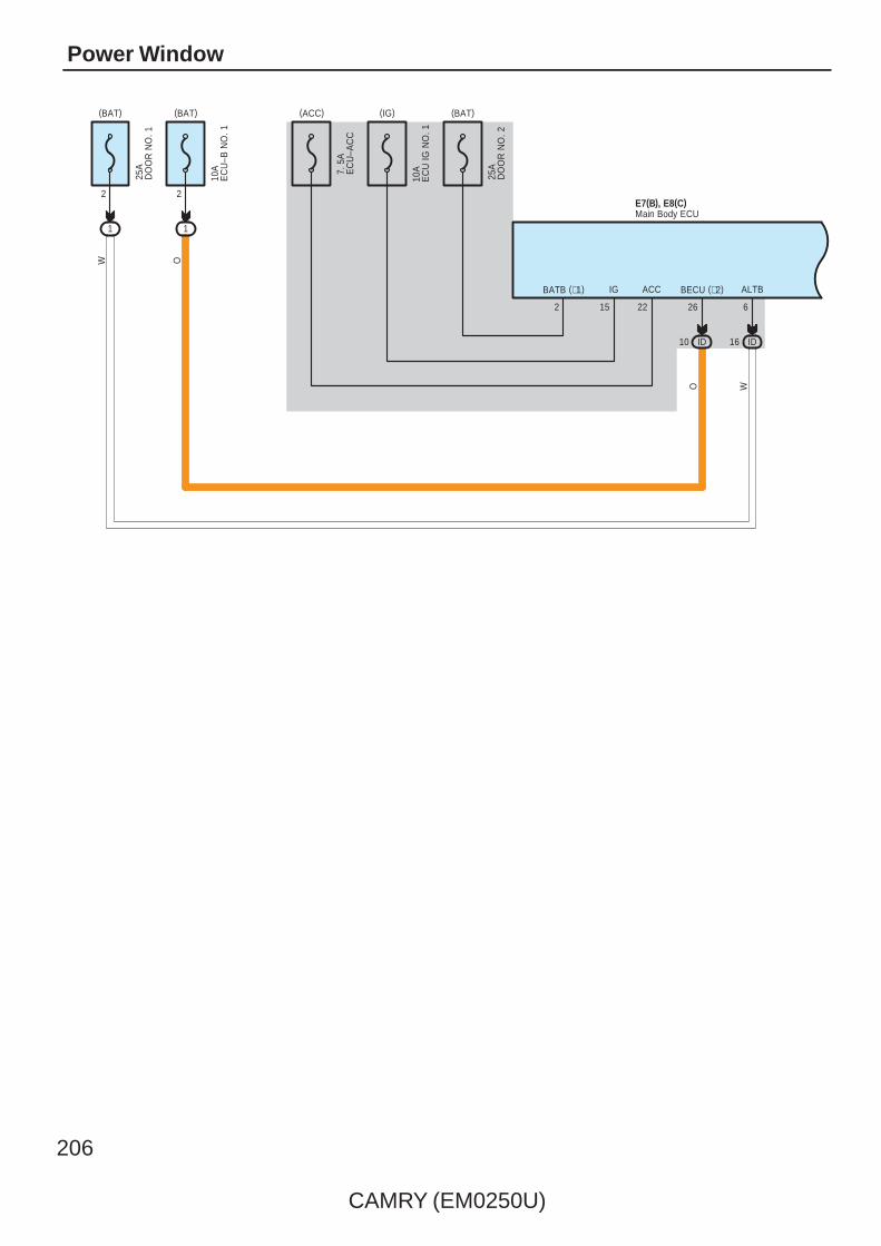
206
CAMRY (EM0250U)
Power Window
(IG)(ACC)
7. 5
AE
CU
–AC
C
10A
EC
U IG
NO
. 1
15
IG
22
ACC
(BAT)
O
BECU (∗2)
26
10 ID
1
2
10A
EC
U–B
NO
. 1
25A
DO
OR
NO
. 1
2
1
(BAT)
ID16
W
ALTB
6
(BAT)
2
BATB (∗1)
25A
DO
OR
NO
. 2
E7(B), E8(C)Main Body ECU
OW

CAMRY (EM0250U)
207
10
F1
12
E2
IM9
GND2
4
W–B
W–B
2
13
24
EN2
N6(
A), (
B)
LL
DCTY
B
L
3O12
3F10
∗ 2 : w/o Smart Key System
Doo
r C
ourte
sy S
W( D
river
's
Sid
e)
W–B
E7(B), E8(C)Main Body ECU
6
∗ 3 : TMC Made
13
∗ 1 : w/ Smart Key System
W–B
(∗4)B1(∗3)A1
∗ 4 : TMMK Made
Junc
tion
Con
nect
orE4
9
W–B
W–B
W–B
W–B
W–B
FE34
W–B
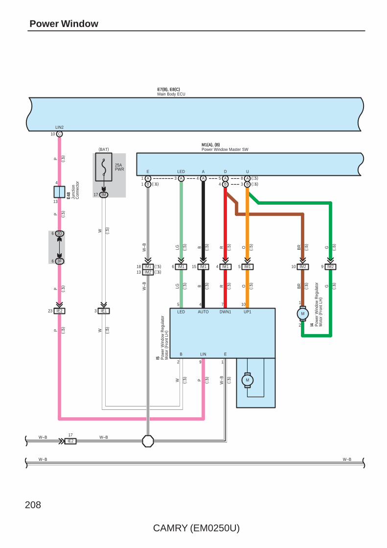
208
CAMRY (EM0250U)
Power Window
E7(B), E8(C)
LED
ELINB
1
9
23 IE2
1
A
IM118IM213
(∗5)(∗6)
6 IM1 15 IM1
10745
IM154
25APWR
IM17
IM1
UDALEDE
W–B LG B R O
W
(BAT)M1(A), (B)
2
C10
3 IE1
3D6
3F6
LIN2
13
PP
4
AUTO DWN1
( ∗5)
UP1
I5
LG ( ∗5) B ( ∗5) R ( ∗5) O ( ∗5)
( ∗5)
W–B
( ∗5)
W ( ∗5)
( ∗5)
P ( ∗5)
W–B
( ∗5)
( ∗5)
P ( ∗5)
P ( ∗5)
( ∗5)
W ( ∗5)
E48
(∗6)B1A3 A4 A5 A8
B3B4
IM210 IM29
1
2
M
BR
BR G
G( ∗6)
( ∗6)
( ∗6)
( ∗6)
I4
Junc
tion
Con
nect
or
Main Body ECU
Pow
er W
indo
w R
egul
ator
Mot
or (
Fron
t LH
)
Pow
er W
indo
w R
egul
ator
Mot
or (
Fron
t LH
)
Power Window Master SW
M
W–B
W–B
W–B
IE217
(∗5)(∗6)
( ∗5)
W–B
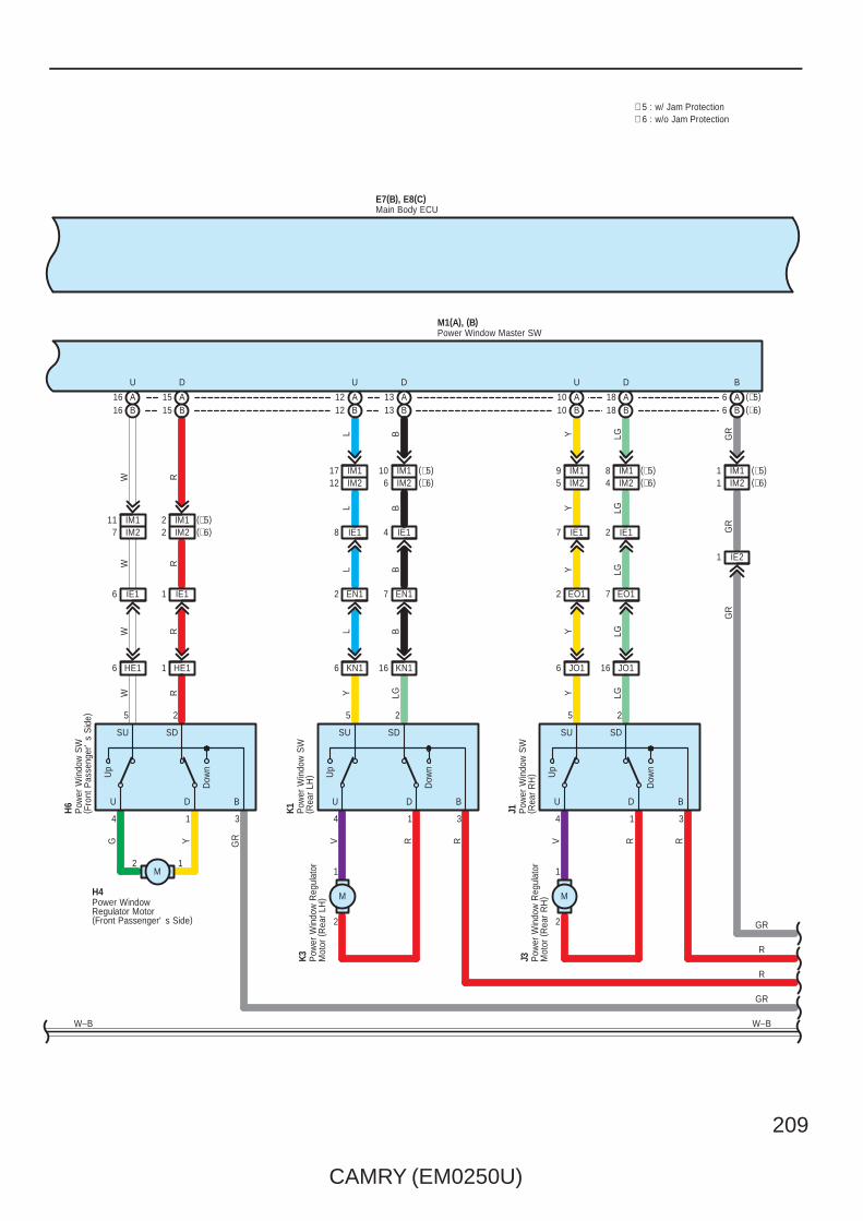
CAMRY (EM0250U)
209
IM110
L
IM26(∗5)
Y
5(∗6)
JO1
8
16
D
SDSU
DU
Dow
n
Up
14
25
U
(∗5)
5 2
4 1
Up
Dow
n
U D
SU SD
B
3
B
3
IE1
6 JO116
IE21
B
A
LG
IM2
DU
7 IE14 IE1
KN16 KN1
L B Y LG
GR
L B Y LG
Y LG Y LG
GR
IM1
K1 J1
IE12
EO12 EO17EN17EN12
L B Y LGRV RRV R
817
E7(B), E8(C)
GR
(∗6)IM2
5 2
4 1
Up
Dow
n
U D
SU SD
12M
B
3
1
DU
HE16 HE1
W R
W R
W R
H6
IE11IE16
W RYG GR
H4
(∗5)
B
129
IM24IM1
6(∗6)B6
A18B18
A10B10
A13B13
A12B12
A15B15
A16B16
IM1
7 IM211 IM1
(∗6)(∗5)
2 IM22 IM1
(∗6)(∗5)
1 IM21 IM1
Main Body ECU
Power WindowRegulator Motor(Front Passenger' s Side)
Pow
er W
indo
w S
W( F
ront
Pas
seng
er'
s S
ide)
Pow
er W
indo
w S
W( R
ear
RH
)
Pow
er W
indo
w S
W( R
ear
LH)
W–B
M1(A), (B)Power Window Master SW
∗ 6 : w/o Jam Protection∗ 5 : w/ Jam Protection
M
Pow
er W
indo
w R
egul
ator
Mot
or (
Rea
r LH
)
K3
M
Pow
er W
indo
w R
egul
ator
Mot
or (
Rea
r R
H)
J3
GR
R
R
GR
W–B
2
1
2
1
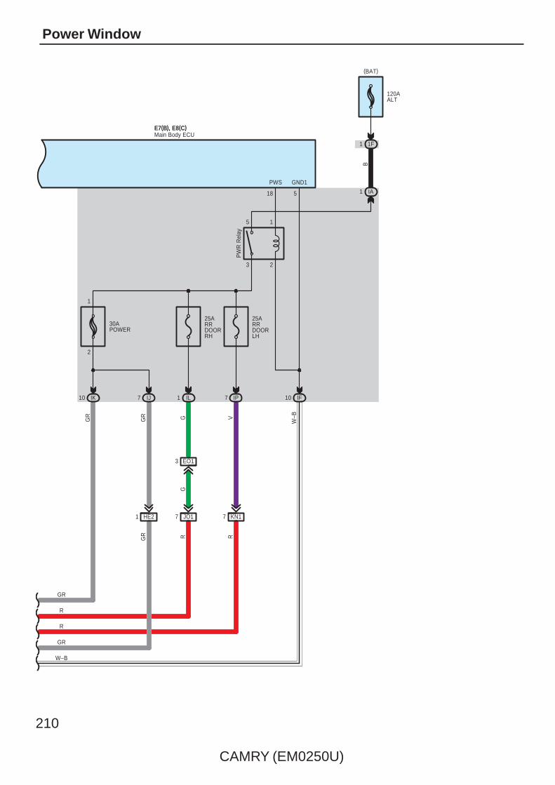
210
CAMRY (EM0250U)
Power Window
E7(B), E8(C)
10
W–B
IA1
IF10
B
GND1
5
3 2
5 1
PW
R R
elay
PWS
18
25ARRDOORLH
IP7
V
25ARRDOORRH
IL1
G
30APOWER
GR
2
1
KN17
R
JO17
EO13
RG
GR
7 IJIK
1 HE2
GR
Main Body ECU
120AALT
1F1
(BAT)
R
GR
R
GR
W–B
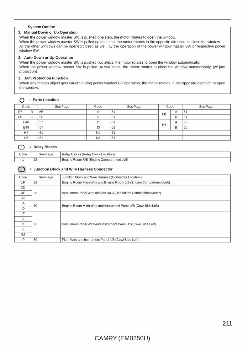
CAMRY (EM0250U)
211
1. Manual Down or Up OperationWhen the power window master SW is pushed one step, the motor rotates to open the window.When the power window master SW is pulled up one step, the motor rotates in the opposite direction, to close the window.All the other windows can be opened/closed as well, by the operation of the power window master SW or respective powerwindow SW.
2. Auto Down or Up OperationWhen the power window master SW is pushed two steps, the motor rotates to open the window automatically.When the power window master SW is pulled up two steps, the motor rotates to close the window automatically. (w/ jamprotection)
3. Jam Protection FunctionWhen any foreign object gets caught during power window UP operation, the motor rotates in the opposite direction to openthe window.
: Parts Location
Code See Page Code See Page Code See Page
E7 B 56 I4 61M1
A 61
E8 C 56 I5 61M1
B 61
E48 57 J1 61N6
A 60
E49 57 J3 61N6
B 60
H4 61 K1 61
H6 61 K3 61
: Relay Blocks
Code See Page Relay Blocks (Relay Block Location)
1 22 Engine Room R/B (Engine Compartment Left)
: Junction Block and Wire Harness Connector
Code See Page Junction Block and Wire Harness (Connector Location)
1F 22 Engine Room Main Wire and Engine Room J/B (Engine Compartment Left)
3D
36 Instrument Panel Wire and J/B No.3 (Behind the Combination Meter)3F 36 Instrument Panel Wire and J/B No.3 (Behind the Combination Meter)
3O
36 Instrument Panel Wire and J/B No.3 (Behind the Combination Meter)
IA30 Engine Room Main Wire and Instrument Panel J/B (Cowl Side Left)
ID30 Engine Room Main Wire and Instrument Panel J/B (Cowl Side Left)
IF
30 Instrument Panel Wire and Instrument Panel J/B (Cowl Side Left)
IJ
30 Instrument Panel Wire and Instrument Panel J/B (Cowl Side Left)IK 30 Instrument Panel Wire and Instrument Panel J/B (Cowl Side Left)
IL
30 Instrument Panel Wire and Instrument Panel J/B (Cowl Side Left)
IM
IP 30 Floor Wire and Instrument Panel J/B (Cowl Side Left)
System Outline

212
CAMRY (EM0250U)
Power Window
: Connector Joining Wire Harness and Wire Harness
Code See Page Joining Wire Harness and Wire Harness (Connector Location)
EN166 Instrument Panel Wire and Floor Wire (Left Kick Panel)
EN266 Instrument Panel Wire and Floor Wire (Left Kick Panel)
EO1 66 Instrument Panel Wire and Floor No.2 Wire (Right Kick Panel)
FE3 66 Instrument Panel No.2 Wire and Instrument Panel Wire (Instrument Panel Center)
HE166 Front Door RH Wire and Instrument Panel Wire (Right Kick Panel)
HE266 Front Door RH Wire and Instrument Panel Wire (Right Kick Panel)
IE166 Front Door LH Wire and Instrument Panel Wire (Left Kick Panel)
IE266 Front Door LH Wire and Instrument Panel Wire (Left Kick Panel)
IM167 Front Door LH Wire and Front Door LH No.2 Wire (Inside of the Front Door LH)
IM267 Front Door LH Wire and Front Door LH No.2 Wire (Inside of the Front Door LH)
JO1 67 Rear Door No.1 Wire and Floor No.2 Wire (Right Center Pillar)
KN1 67 Rear Door No.2 Wire and Floor Wire (Left Center Pillar)
: Ground Points
Code See Page Ground Points Location
E2 66 Instrument Panel Brace LH
F1 66 Instrument Panel Left

CAMRY (EM0250U)
213
Memo

214
CAMRY (EM0250U)
Door Lock Control and Luggage Compartment Door Opener
E6(A), E7(B), E8(C), E9(D)Main Body ECU
(IG) (ACC)
15
IG
22
ACC
7. 5AECU–ACC
10AECU IGNO. 1
(BAT)
O
BECU(∗2)
26
10 ID
1
2
10AECU–BNO. 1
25ADOORNO. 1
2
1
(BAT)
ID16
W
ALTB
6
(BAT)
2
BATB(∗1)
25ADOORNO. 2
OW

CAMRY (EM0250U)
215
∗ 1 : w/ Smart Key System
E6(A), E7(B), E8(C), E9(D)Main Body ECU
∗ 2 : w/o Smart Key System∗ 3 : TMC Made∗ 4 : TMMK Made
W B
3 SN1
WW
A
W–B
S5
B
S1
B
B
TR+
5 EN1
1
2
M
EN217
3
W
LGCY
9
1
25 1
14
SN116
21
13
24
LCTY
17
EN2
N6(
A), (
B)
L
EO25
1
O6
Y
EO2
N13
( A) ,
( B)
6
1
O10
GR
3C7
3N6
L
DCTY
B
PCTY
A
RCTY
L
IO7
Y
LG
GR Y
7
3O12
3F10
3C6
GR
A
3N5
13
W–B
N28
S15
Doo
r C
ourte
sy S
W( R
ear
LH)
Junc
tion
Con
nect
or
Doo
r C
ourte
sy S
W( D
river
's
Sid
e)
Doo
r C
ourte
sy S
W( R
ear
RH
)
Doo
r C
ourte
sy S
W( F
ront
Pas
seng
er'
s S
ide)
Junc
tion
Con
nect
or
Doo
r Lo
ck A
ssem
bly
( Lug
gage
)
(∗4)B1(∗3)A1
(∗4)B1(∗3)A1
A5(∗1)(∗2)
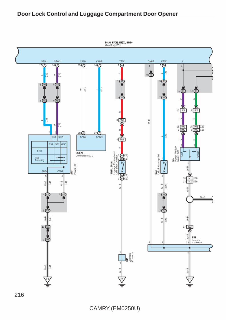
216
CAMRY (EM0250U)
Door Lock Control and Luggage Compartment Door Opener
IM9
6
GND2
4
W–B
W–B
R
A2
TSW
GV
3A2
2
1
3J5
3A7
LL
W–B
Unl
ock
Lock
1
2 9
M1
E22
IK15 IK12
L1
9
IE215 IE27
IE217
D
KSW
3 3C
13
V G
V G
W–B
W–B
W–B
R
E2
5
R
1
9
S1
IM2
(∗2)B2(∗1)A1
(∗1)A3(∗2)B1
( ∗2)
( ∗2)
( ∗2)
( ∗2)
13 IM13 (∗6)
(∗5)14
3F2
3N3
EN28
W–B
R
SN14
(∗6)1813 IM2
IM1 (∗5)
W–B
2
S15
W–B
IM18 IM2
Unl
ock
War
ning
SW
Pow
er W
indo
wM
aste
r S
W
Junc
tion
Con
nect
or
Lugg
age
Com
partm
ent
Doo
r Lo
ck C
ylin
der
S6( B
) , S8
( A)
( ∗1)
IG10
IM3
W–B
W–B
E1
B17 B16
SSW1 SSW2
7 2
GND COM
5 4
4 4E 5 4E
W–B
SS1
SS2SS1
FullTraveling
Free
GND
SS2
W–B
4H5
4G7
4E7
4G6
4E6
VL
V
L
Pow
er S
WE5
2
28 A
C15 C16
CANN
L
A
( ∗1)
( ∗1)
CANHCANL
27
CANP
W
E58(A)Certification ECU
( ∗1)
( ∗1)
( ∗1)
( ∗1)
( ∗1)
( ∗1)
( ∗1)
JunctionConnector
E49
W–B
W–B
9
E6(A), E7(B), E8(C), E9(D)Main Body ECU

CAMRY (EM0250U)
217
B
25
L G
IE2
GR
GR
GR
HE2
UL2
Unl
ock
Lock
3
4 2
H5
IJ3 IJ4
UL1
12
HE215 HE27K
ey L
ock
Key
Unl
ock
910
7
8
IK7
IE216IE224 IE29
1
4
8 IE2
24
IK16 IK2
L2
10
ACT+
1
HE217
5
L G
RL BR
BR W
W
W–B
W–B
W–B
GR
25
Key
Loc
k
Key
Unl
ock
5 6
8
7
HE28 HE216 HE29
1
4
IJ1IJ5
LLG GR W
WLG GR L
H8
10
UL3
W–B
ACTD
5
HE1
B
5 3I
5 3O
9 3I
9 3G
7
B9
LSWD
LL
GR
W–B LG
W
LG
Doo
r Lo
ckC
ontro
l SW
Doo
r Lo
ck A
ssem
bly
( Fro
nt P
asse
nger
's
Sid
e)
LGL
Door Lock Assembly(Driver' s Side)
I7
W–B
E6(A), E7(B), E8(C), E9(D)Main Body ECUE6(A), E7(B), E8(C), E9(D)Main Body ECU
W–B
GR
10 W–B
JunctionConnector
E49
LG
W–B
MM
W–B
LG
∗ 1 : w/ Smart Key System∗ 2 : w/o Smart Key System∗ 5 : w/ Jam Protection∗ 6 : w/o Jam Protection

218
CAMRY (EM0250U)
Door Lock Control and Luggage Compartment Door Opener
N1
IJ2
9
6
KN13KN11
1
4
KN110
IP6 IP11
9
6
JO13JO11
1
4
JO110
IF18 IF5
LSWP
27 A
EO18 EO14 EO116
KN14 JO14
B L GR B L GR
LB GR
B LG W
2
W–B
W–B
ACT–
3K5 J5
W–B
LG
N29
5 IL
O1
O218
W–B
G W GR
GR
20
IP5
LSR (∗2)LSWL (∗1)
GR
( ∗2)
3O
3D
A5
LSWR
VLGGR
(∗1)
( ∗1)
Doo
r Lo
ck A
ssem
bly
( Rea
r R
H)
Doo
r Lo
ck A
ssem
bly
( Rea
r LH
)
JunctionConnector
JunctionConnector
W–B
IF10
GND1
5
W–B
E6(A), E7(B), E8(C), E9(D)Main Body ECUE6(A), E7(B), E8(C), E9(D)Main Body ECU
∗ 7 : 2GR–FE∗ 8 : 2AZ–FE
∗ 2 : w/o Smart Key System∗ 1 : w/ Smart Key System
4
4
( ∗7)
BR
GR
BR
BR
C57
15 EA1
( ∗8)
( ∗8)
( ∗7)
( ∗7)
A41(
A), A
42( B
)
GR
W–B
W–B
3
C7
4 CA3
17 A
18 B
C6
4 CA3
10 3D
5 3Q
Junc
tion
Con
nect
or
JunctionConnector
LGBR
BR
MM
LG

CAMRY (EM0250U)
219
WB
DRIVE IC
+B(DOME)
MICRO COMPUTER
B2 B
Mas
ter
War
ning
17 A A18A24
1
V
IG+
A
1 3D
12 3Q
10AMPX–B
(BAT)
2
R
R
LG
A
12 3L
1 3Q
13 ID
7 IF
1
10ADOME
(BAT)
2
Power SupplyCircuit
13
GR
GR
A
2 3G
9 3Q
12 IG
7. 5AGAUGENO. 2
(IG)
12 A
EA12
V
V
SB
3Q7
3U2
F1
W–B
W–BBR
ES CANH CANLE2
F1(A)Combination Meter
W
B
GR
P
73 B
B2
B6R
P
Par
k/N
eutra
lP
ositi
on S
W
C1(
B)( ∗
8)( ∗
8)
BW
CANHCANL
41 A49 A
( ∗8)
( ∗8)
Engine Control ModuleA24(A), C24(B)
E6(A), E7(B), E8(C), E9(D)Main Body ECU
1A3
BR
W(∗8)
B(∗8)
R(∗8)MULTI LCD
CANI/F

220
CAMRY (EM0250U)
Door Lock Control and Luggage Compartment Door Opener
B
W BBW
CANHCANL
5 C6 C
W
W
B
A49 A41
CANL CANH
W B
A1 A7
B4 B10 2 A 1 A 2 B 1 B
2 C 1 C
BW
WB
Junc
tion
Con
nect
orE4
2(A)
, E43
( B) ,
E44(
C) ,
E45(
D)
DBE–
BB
DBE+
RG
1211
A22 A13
D2 D1
W BCANL CANH
31
LBE+ LBE–
Airb
ag S
enso
rA
ssem
bly
Cen
ter
E30(
A), N
1(B)
Junc
tion
Con
nect
orA4
0(A)
, E41
( B)
O
10 CA2
(IG)
16 IH
10AGAUGENO. 1
14 EA1
R
A1
A3
RP
Par
k/N
eutra
lP
ositi
on S
W
C1(
A)
24
B–W
B
P
( ∗7)
( ∗7)
WWBB ( ∗8)
( ∗7)
( ∗8)
( ∗7)
( ∗7)
( ∗7)
Engine Control ModuleA55(A), C55(B)
E6(A), E7(B), E8(C), E9(D)Main Body ECU
∗ 7 : 2GR–FE∗ 8 : 2AZ–FE
Front Seat Inner Belt(Driver' s Side)
N3
14 FE3 13 FE3
W(∗8)
B(∗8)
R(∗8)
Buckle SW

CAMRY (EM0250U)
221
1. Manual Unlock OperationWhen the door lock control SW of the driver’s or passenger’s side door is pushed to UNLOCK, the door lock will unlock.
2. Manual Lock OperationWhen the door lock control SW of the driver’s or passenger’s side door is pushed to LOCK, the door lock will lock.
3. Door Key Unlock Operation∗ Unlock operation from driver’s side doorWhen the driver’s side door is unlocked once using the ignition key, only the driver’s side door is unlocked. If this operation isrepeated within 3 seconds, all the other doors are unlocked.
: Parts Location
Code See Page Code See Page Code See Page
A24 A 52 (2AZ–FE) E41 B 57N3
62 (*1)
A40 A 59 E42 A 57N3
63 (*2)
A41 A 59 E43 B 57N6
A 60
A42 B 59 E44 C 57N6
B 60
A55 A 49 (2GR–FE) E45 D 57N13
A 60
C1A 50 (2GR–FE) E49 57
N13B 60
C1B 54 (2AZ–FE) E52 57 N28 60
C24 B 55 (2AZ–FE) E58 A 57 N29 60
C55 B 51 (2GR–FE) F1 A 58 O6 60
C57 51 (2GR–FE) H5 61 O10 60
E6 A 56 H8 61 O21 60
E7 B 56 I7 61 S5 61
E8 C 56 J5 61 S6 B 61
E9 D 56 K5 61 S8 A 61
E22 56 M1 61 S15 61
E30 A 56 N1 B 59
: Relay Blocks
Code See Page Relay Blocks (Relay Block Location)
1 22 Engine Room R/B (Engine Compartment Left)
* 1 : w/ Power Seat * 2 : w/o Power Seat
System Outline

222
CAMRY (EM0250U)
Door Lock Control and Luggage Compartment Door Opener
: Junction Block and Wire Harness Connector
Code See Page Junction Block and Wire Harness (Connector Location)
1A 25 Engine Room Main Wire and Engine Room J/B (Engine Compartment Left)
3A
36 Instrument Panel Wire and J/B No.3 (Behind the Combination Meter)
3C
36 Instrument Panel Wire and J/B No.3 (Behind the Combination Meter)
3D
36 Instrument Panel Wire and J/B No.3 (Behind the Combination Meter)
3F
36 Instrument Panel Wire and J/B No.3 (Behind the Combination Meter)3G
36 Instrument Panel Wire and J/B No.3 (Behind the Combination Meter)3I
36 Instrument Panel Wire and J/B No.3 (Behind the Combination Meter)
3J
3L
3N
3O
3Q36 Instrument Panel No.2 Wire and J/B No.3 (Behind the Combination Meter)
3U36 Instrument Panel No.2 Wire and J/B No.3 (Behind the Combination Meter)
4E
42 Instrument Panel Wire and J/B No.4 (Instrument Panel Brace Center)4G 42 Instrument Panel Wire and J/B No.4 (Instrument Panel Brace Center)
4H
42 Instrument Panel Wire and J/B No.4 (Instrument Panel Brace Center)
ID 30 Engine Room Main Wire and Instrument Panel J/B (Cowl Side Left)
IF 30
Instrument Panel Wire and Instrument Panel J/B (Cowl Side Left)
IG31
Instrument Panel Wire and Instrument Panel J/B (Cowl Side Left)
IH31
Instrument Panel Wire and Instrument Panel J/B (Cowl Side Left)IJ
30
Instrument Panel Wire and Instrument Panel J/B (Cowl Side Left)
IK30
Instrument Panel Wire and Instrument Panel J/B (Cowl Side Left)
IL30
IM
IO30 Floor Wire and Instrument Panel J/B (Cowl Side Left)
IP30 Floor Wire and Instrument Panel J/B (Cowl Side Left)
: Connector Joining Wire Harness and Wire Harness
Code See Page Joining Wire Harness and Wire Harness (Connector Location)
CA264 (2GR–FE)
Engine Wire and Engine Room Main Wire (Inside of the Engine Room R/B and Engine Room J/B)
CA265 (2AZ–FE)
Engine Wire and Engine Room Main Wire (Inside of the Engine Room R/B and Engine Room J/B)
CA364 (2GR–FE)
Engine Wire and Engine Room Main Wire (Inside of the Engine Room R/B and Engine Room J/B)
CA365 (2AZ–FE)
EA1 66 Instrument Panel Wire and Engine Room Main Wire (Left Kick Panel)
EN166 Instrument Panel Wire and Floor Wire (Left Kick Panel)
EN266 Instrument Panel Wire and Floor Wire (Left Kick Panel)
EO166 Instrument Panel Wire and Floor No.2 Wire (Right Kick Panel)
EO266 Instrument Panel Wire and Floor No.2 Wire (Right Kick Panel)
FE3 66 Instrument Panel No.2 Wire and Instrument Panel Wire (Instrument Panel Center)
HE166 Front Door RH Wire and Instrument Panel Wire (Right Kick Panel)
HE266 Front Door RH Wire and Instrument Panel Wire (Right Kick Panel)
IE2 66 Front Door LH Wire and Instrument Panel Wire (Left Kick Panel)
IM167 Front Door LH Wire and Front Door LH No.2 Wire (Inside of the Front Door LH)
IM267 Front Door LH Wire and Front Door LH No.2 Wire (Inside of the Front Door LH)
JO1 67 Rear Door No.1 Wire and Floor No.2 Wire (Right Center Pillar)
KN1 67 Rear Door No.2 Wire and Floor Wire (Left Center Pillar)
SN1 67 Luggage Room Wire and Floor Wire (Luggage Room Left)

CAMRY (EM0250U)
223
: Ground Points
Code See Page Ground Points Location
C6 65 (2AZ–FE) Cylinder Block
C7 64 (2GR–FE) Left Side of the Cylinder Block
E1 66 Instrument Panel Left
E2 66 Instrument Panel Brace LH
F1 66 Instrument Panel Left
N1 67 Left Rear Quarter Panel
O1 67 Right Rear Quarter Panel
S1 67 Lower Back Panel Center
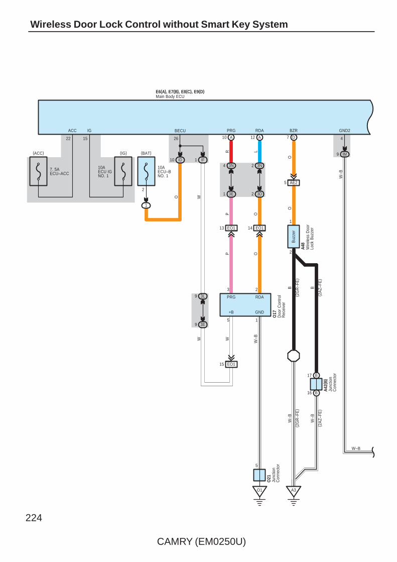
224
CAMRY (EM0250U)
Wireless Door Lock Control without Smart Key System
(IG)(ACC)
1210
O1
7. 5AECU–ACC
10AECU IGNO. 1
15
IG
22
ACC
O17
O
(BAT)
O W
BECU
26
W
9 3E
9 3L
1 IF10 ID
1
2
10AECU–BNO. 1
W–BW
OP
LR
+B GND
5 1
23
EO115
14 EO1
A
RDA
RDAPRG
13 EO1
A
PRG
5
E6(A), E7(B), E8(C), E9(D)
IM9
GND2
4
1
2
A48
A42(
B)( 2
AZ–
FE)
( 2G
R–F
E)
( 2A
Z–FE
)
W–B
BBO
O
16 B
17 B
A3
Buz
zer
BZR
D
3N2
3D2
3N4
3E1
P
Junc
tion
Con
nect
or
Wire
less
Doo
rLo
ck B
uzze
r
Main Body ECU
Doo
r C
ontro
lR
ecei
ver
7
O21
Junc
tion
Con
nect
or
W–B
W–B
AE25
( 2G
R–F
E)
W–B

CAMRY (EM0250U)
225
B
N1
W–BW–B
25
IE2
HE2
3A2
2
1
3J5
LL
W–B
E22 7
8
IE224 IE29
1
4
IK2
ACT+
1D
KSW
12
9
IJ
RL
W
2
W
W–B
I7
5
GR
25
8
7
HE29
1
4
IJ1
9
6
KN13KN11
1
4
KN110
IP6 IP11
LSWP
27 A
KN14
LLG B L GR
G W
LG L
2
W–B
H8
K5
W–B
ACTD
5
HE1
LG
N29
5 3I
5 3O
W–B
2
W–B
7
B9
LSWDL
G W GR
W–B
LG
GR
20
IP5
LSR
LG
E49
LG
Unl
ock
War
ning
SW
JunctionConnector
Doo
r Lo
ck A
ssem
bly
( Fro
nt P
asse
nger
's
Sid
e)
Doo
r Lo
ck A
ssem
bly
( Rea
r LH
)
JunctionConnector
GR
LGL
3C3
3A7
Doo
r Lo
ck A
ssem
bly
( Driv
er'
s S
ide)
IE217
HE217
5
W–B
13
W–B
W–B
W–B
W–B
W–B
E6(A), E7(B), E8(C), E9(D)Main Body ECU
E2F1
6
W–B
W–B
M
M M
4FE3
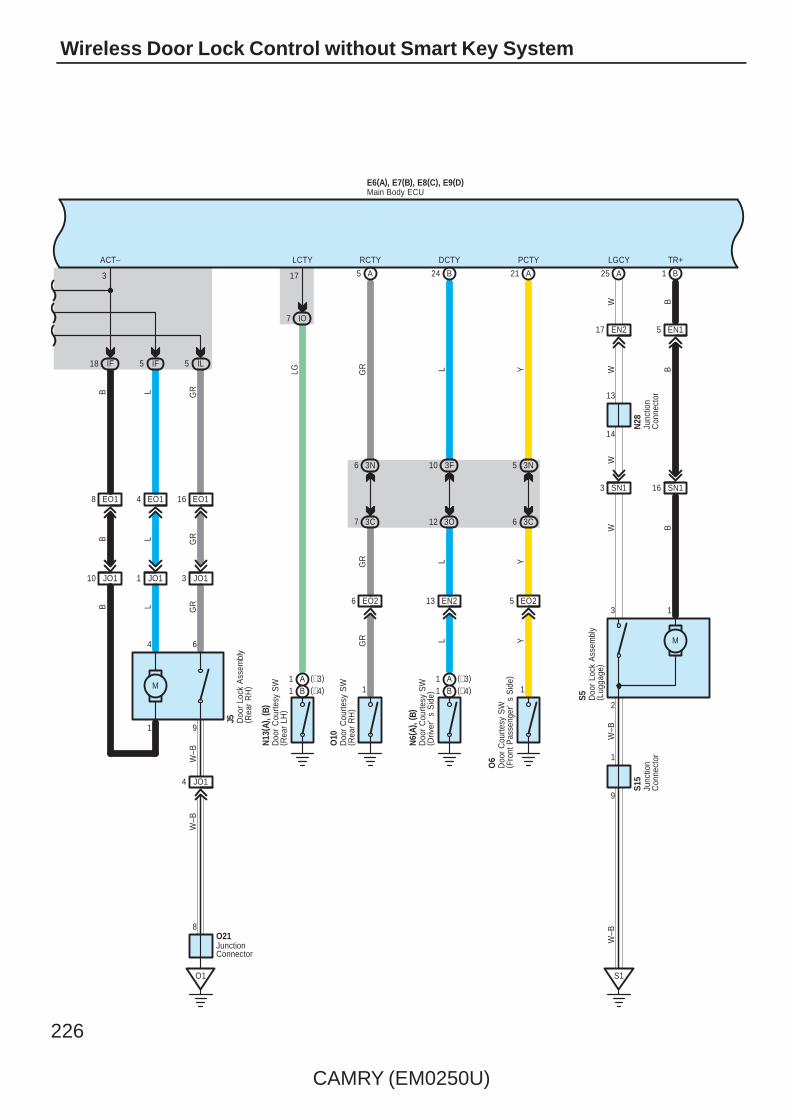
226
CAMRY (EM0250U)
Wireless Door Lock Control without Smart Key System
W B
3 SN1
W
9
6
JO13JO11
1
4
JO110
IF18 IF5
EO18 EO14 EO116
JO14
B L GR
LB GR
B L
W–B
ACT–
3
J5
W
A
W–B
S5
B
S1
B
B
TR+
5 EN1
1
2
M
EN217
3W
LGCY
9
1
W–B
25 1
14
SN116
5 IL
O1
O218
21
13
24
LCTY
17
EN2
N6(
A), (
B)
L
EO25
1
O6
Y
EO2
N13
( A) ,
( B)
6
1
O10
GR
3C7
3N6
L
DCTY
B
PCTY
A
RCTY
L
IO7
YLG
GR Y
5
3O12
3F10
3C6
GR
A
3N5
13
W–B
N28
S15
GR
Doo
r Lo
ck A
ssem
bly
( Rea
r R
H)
Doo
r C
ourte
sy S
W( R
ear
LH)
Junc
tion
Con
nect
or
Doo
r C
ourte
sy S
W( D
river
's
Sid
e)
Doo
r C
ourte
sy S
W( R
ear
RH
)
JunctionConnector
Doo
r C
ourte
sy S
W( F
ront
Pas
seng
er'
s S
ide)
Junc
tion
Con
nect
or
Doo
r Lo
ck A
ssem
bly
( Lug
gage
)
E6(A), E7(B), E8(C), E9(D)Main Body ECU
(∗4)B1(∗3)A1
(∗4)B1(∗3)A1
M

CAMRY (EM0250U)
227
E6(A), E7(B), E8(C), E9(D)
LG
WR
( ∗1)V
( ∗2)
W( ∗
2)
B
( ∗1)
( ∗1)
( ∗1)
6
EQ116
IR5 II10
BR
V
10ADOME
2
1
LG
BR
(BAT)
ILE
21
W ( ∗1)
( ∗2)
CTY
7
2
IF7
EQ17
IL10
2
6
R
RR
1
WW
6 IR
15 EQ1
ID13
E25
3B12
R
BR
ILL+
ILL–
HAZ
C
W
4
3L12
Q6
Igni
tion
Key
Cyl
inde
rLi
ght
∗ 1 : w/ Sliding Roof
Tran
spon
der
Key
Am
plifi
er
Main Body ECU
Ove
rhea
d J/
B
OFF
ON
DO
OR
3M9
3F9
8
HAZ
Turn SignalFlasher
E14
W
∗ 2 : w/o Sliding Roof
( ∗2)
( ∗2)
∗ 3 : TMC Made∗ 4 : TMMK Made
GND1
5
IF10 IR1
E2
2
10
Roo
m L
amp
( Cen
ter)
Q9
18EQ1
W–B
W–B
( ∗1)
W–B
W( ∗
2)
W–B
JunctionConnector
E49
11
W–B
W–B
( ∗1)
EQ111
( ∗1)
8
E
3
WW–B
(∗2)(∗2)
Map Lamp

228
CAMRY (EM0250U)
Wireless Door Lock Control without Smart Key System
Door lock control (Lock and unlock) and panic control (Theft alarm and flash) is performed by remote control, without theignition key inserted in the door key cylinder, using low–power electrical waves emitted by a transmitter.
1. Wireless Door Lock or Unlock Normal OperationWith the ignition key not inserted into the ignition key cylinder (Unlock warning SW off) and all the doors completely closed,when the lock or unlock button (Transmitter) is pushed, the door control receiver receives the electrical waves from thetransmitter, and sends a signal to the main body ECU, causing it to operate.As a result, the main body ECU judges whether the door is locked or unlocked based on the signal from the door lock motorand door unlock detection SW, and sends a signal to switch the condition from lock to unlock or vice versa, causing the doorlock motor to operate.
2. Visual Confirmation of Lock or UnlockIf all doors indicate that they are locked after the lock command, turn signal light will flash once. If any door indicates that it isopen after the unlock command, turn signal light will flash twice.
3. Buzzer Sound FunctionIf all doors indicate that they are locked after the lock command, the keyless buzzer goes on once. If any door indicates thatit is open after the unlock command, the keyless buzzer goes on twice.
4. Illuminated Entry FunctionWhen the main body ECU detects the unlock state after the unlock operation has been made, it turns on the lights, such asthe ignition key cylinder light and interior light for approx. 15 sec. If all the doors are locked during this operation, lighting iscancelled and the lights immediately fade out.
5. Wireless Door Unlock OperationPushing the unlock button (Transmitter) once, driver’s door is unlocked. Furthermore, pushing the button again within 3seconds, the other doors are unlocked.
6. Automatic Lock OperationWith the ignition key not inserted into the ignition key cylinder (Unlock warning SW off) and all the doors completely closed,after pushing the button (Transmitter) to unlock all the doors, if a door is not opened within 30 seconds, all the doors will beautomatically relocked.
7. Wireless Control Stop FunctionIf a door is open (Door courtesy SW on), a signal is input from the door courtesy SW to the main body ECU stoppingwireless door lock or unlock.If the ignition key is in the ignition key cylinder (Unlock warning SW on), the unlock warning SW inputs a signal to the mainbody ECU stopping wireless door lock or unlock.
8. Repeat FunctionIf the door lock or unlock condition does not change after wireless door lock or unlock operation, 2 seconds later, the mainbody ECU sends current again to the door lock motor.
9. Remote Panic OperationPanic will function when doors are locked or unlocked, open or closed. When the panic button (Transmitter) is pushed once,theft alarm and horn sounds and turn signal light, headlights and taillight flash. Then, the panic or the unlock button(Transmitter) is pushed once more, sounding and flashing will stop. Panic will not function when ignition key is in ignition keycylinder.
: Parts Location
Code See Page Code See Page Code See Page
A42 B 59 E49 57 N29 60
A4849 (2GR–FE) H8 61 O6 60
A4853 (2AZ–FE) I7 61 O10 60
E6 A 56 J5 61 O17 60
E7 B 56 K5 61 O21 60
E8 C 56N6
A 60 Q6 61
E9 D 56N6
B 60 Q9 61
E14 56N13
A 60 S5 61
E22 56N13
B 60 S15 61
E25 56 N28 60
System Outline
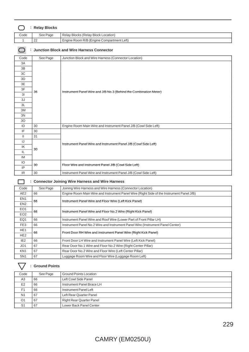
CAMRY (EM0250U)
229
: Relay Blocks
Code See Page Relay Blocks (Relay Block Location)
1 22 Engine Room R/B (Engine Compartment Left)
: Junction Block and Wire Harness Connector
Code See Page Junction Block and Wire Harness (Connector Location)
3A
36 Instrument Panel Wire and J/B No.3 (Behind the Combination Meter)
3B
36 Instrument Panel Wire and J/B No.3 (Behind the Combination Meter)
3C
36 Instrument Panel Wire and J/B No.3 (Behind the Combination Meter)
3D
36 Instrument Panel Wire and J/B No.3 (Behind the Combination Meter)
3E
36 Instrument Panel Wire and J/B No.3 (Behind the Combination Meter)3F
36 Instrument Panel Wire and J/B No.3 (Behind the Combination Meter)3I
36 Instrument Panel Wire and J/B No.3 (Behind the Combination Meter)
3J
3L
3M
3N
3O
ID 30 Engine Room Main Wire and Instrument Panel J/B (Cowl Side Left)
IF 30
Instrument Panel Wire and Instrument Panel J/B (Cowl Side Left)
II 31
Instrument Panel Wire and Instrument Panel J/B (Cowl Side Left)IJ
30
Instrument Panel Wire and Instrument Panel J/B (Cowl Side Left)IK
30
Instrument Panel Wire and Instrument Panel J/B (Cowl Side Left)
IL30
IM
IO30 Floor Wire and Instrument Panel J/B (Cowl Side Left)
IP30 Floor Wire and Instrument Panel J/B (Cowl Side Left)
IR 30 Instrument Panel Wire and Instrument Panel J/B (Cowl Side Left)
: Connector Joining Wire Harness and Wire Harness
Code See Page Joining Wire Harness and Wire Harness (Connector Location)
AE2 66 Engine Room Main Wire and Instrument Panel Wire (Right Side of the Instrument Panel J/B)
EN166 Instrument Panel Wire and Floor Wire (Left Kick Panel)
EN266 Instrument Panel Wire and Floor Wire (Left Kick Panel)
EO166 Instrument Panel Wire and Floor No.2 Wire (Right Kick Panel)
EO266 Instrument Panel Wire and Floor No.2 Wire (Right Kick Panel)
EQ1 66 Instrument Panel Wire and Roof Wire (Lower Part of Front Pillar LH)
FE3 66 Instrument Panel No.2 Wire and Instrument Panel Wire (Instrument Panel Center)
HE166 Front Door RH Wire and Instrument Panel Wire (Right Kick Panel)
HE266 Front Door RH Wire and Instrument Panel Wire (Right Kick Panel)
IE2 66 Front Door LH Wire and Instrument Panel Wire (Left Kick Panel)
JO1 67 Rear Door No.1 Wire and Floor No.2 Wire (Right Center Pillar)
KN1 67 Rear Door No.2 Wire and Floor Wire (Left Center Pillar)
SN1 67 Luggage Room Wire and Floor Wire (Luggage Room Left)
: Ground Points
Code See Page Ground Points Location
A3 66 Left Cowl Side Panel
E2 66 Instrument Panel Brace LH
F1 66 Instrument Panel Left
N1 67 Left Rear Quarter Panel
O1 67 Right Rear Quarter Panel
S1 67 Lower Back Panel Center
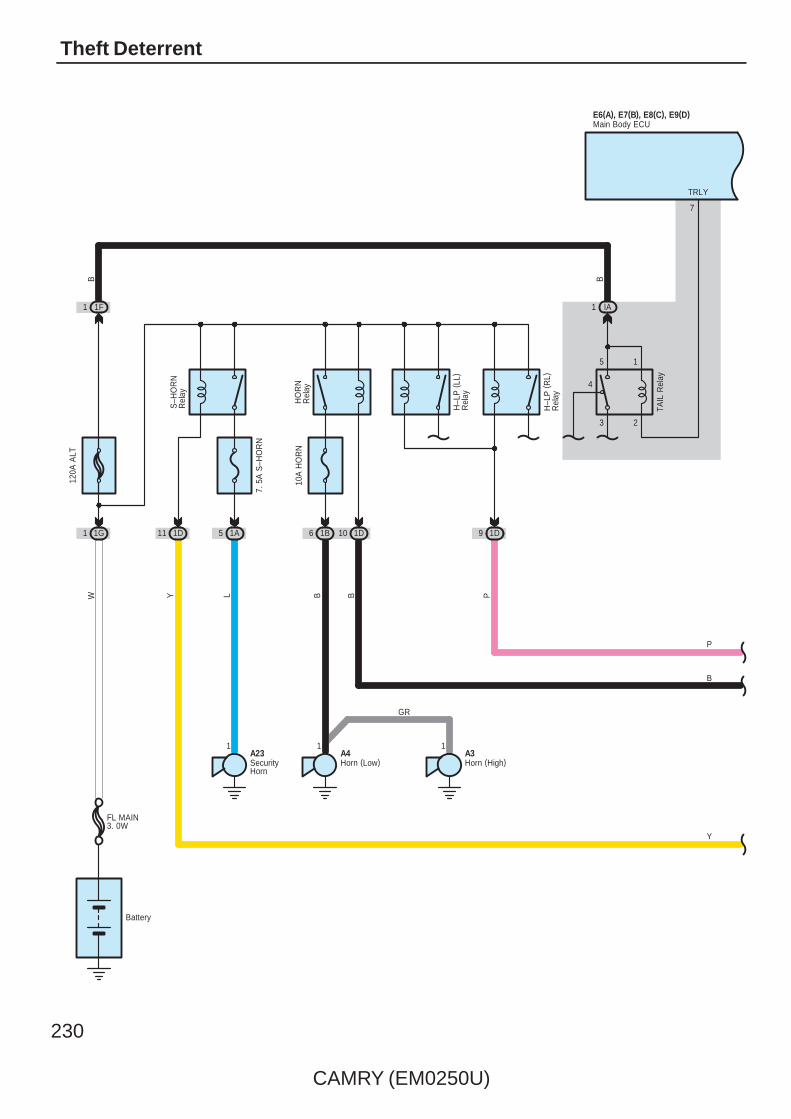
230
CAMRY (EM0250U)
Theft Deterrent
Battery
5 1A
S–H
OR
NR
elay
Y
1G1
120A
ALT
W
1
L
7. 5
A S
–HO
RN
1F1
P
9 1D
H–L
P (
RL)
Rel
ay
H–L
P (
LL)
Rel
ay
3 2
5 1
IA1
TRLY
7
TAIL
Rel
ay
11 1D
FL MAIN3. 0W
BB
10 1D1B6
A411
A3
B B
GR
Horn (High)Horn (Low)
HO
RN
Rel
ay10
A H
OR
N
A23SecurityHorn
E6(A), E7(B), E8(C), E9(D)Main Body ECU
P
B
Y
4

CAMRY (EM0250U)
231
28 A
C15 C16
CANN
L
A
( ∗1)
( ∗1)
CANHCANL
27
CANP
P
SH
12 AE6
6 D
HRLY
8
B
11 ID
(IG)(ACC)
7. 5AECU–ACC
10AECU IGNO. 1
15
IG
22
ACC
W
Y
E6(A), E7(B), E8(C), E9(D)
25
HORN
Main Body ECU
7
W
11
37 A
4
VV
ASEL
ASEL
EO1 EO1
R
RSSIY
RDA
R
5
RSSI
Y
3
DATA+5
RC0
GG
2
W–B
6
GNDANT
6
A29 A38 A39
A2
HSW
RR
W
B24
1
2
AE22
R
14 EO113 EO112
O1
ANT
3
10 3J
11 3E
O21
O18
Doo
r C
ontro
lR
ecei
ver
Junc
tion
Con
nect
or
O19
Ele
ctric
alK
ey A
nten
na
1
A43
Junc
tion
Con
nect
or
A5 Eng
ine
Hoo
dC
ourte
sy S
W
Certification ECUE58(A), E59(B)
( ∗1)
( ∗1)
( ∗1)
( ∗1)
( ∗1)
( ∗1)
( ∗1)
( ∗1)
( ∗1)
( ∗1)
( ∗1)
( ∗1)
( ∗1)
( ∗1)
P
3 ID
Y
B
P
∗ 1 : w/ Smart Key System
2 A
IND
Y ( ∗1)
Y
(∗1)
20 B
( ∗1)
SH–
P
( ∗2)
∗ 2 : w/o Smart Key System
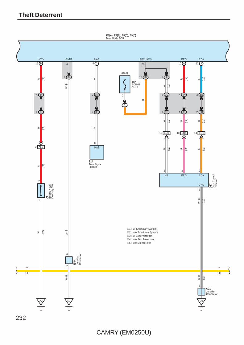
232
CAMRY (EM0250U)
Theft Deterrent
( ∗2)
( ∗2)
( ∗2)
1210
O21
O1
W–B
O17
O
(BAT)
O
W
BECU (∗2)
26
W
9 3E
9 3L
1 IF10 ID
1
2
10AECU–BNO. 1
W–B
W OP
LRGND
1
23
14 EO1
A
RDA
RDAPRG
13 EO1
A
PRGHAZ
C
W
4
5
B16
3F4
3J4
AE22
2
1
E6(A), E7(B), E8(C), E9(D)
A2
HCTY
RR
RW
IM9
GND2
4W
–B
3N2
3D2
3N4
3E1
P
( ∗2)
Main Body ECU
Doo
r C
ontro
lR
ecei
ver
JunctionConnector
Eng
ine
Hoo
dC
ourte
sy S
W
A5
( ∗2)
( ∗2)
( ∗2)
( ∗2)
( ∗2)
( ∗2)
( ∗2)
( ∗2)
( ∗2)
( ∗2)
( ∗2)
E2
2
6
W–B
W–B
Junc
tion
Con
nect
or
E49
3M9
3F9
8
HAZ
Turn SignalFlasher
E14
W
EO115
5
+B
∗ 1 : w/ Smart Key System∗ 2 : w/o Smart Key System∗ 3 : w/ Jam Protection∗ 4 : w/o Jam Protection
Y
(∗1)
Y
(∗1)
∗ 5 : w/o Sliding Roof
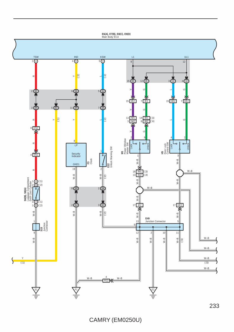
CAMRY (EM0250U)
233
E6(A), E7(B), E8(C), E9(D)
( ∗2)
W–B
W–B
GND1
W–B
10
4
R
11 3R
6 3K
YY
D
IND
A2
TSW
G
L G
V
3A2
2
1
3J5
3A7
LL
W–B
Unl
ock
Lock
1
2 9
Unl
ock
Lock
3
4 2
M1
H5
IK15 IK12 IJ3 IJ4
L1 UL1
9 12
IE215 IE27 HE215 HE27
IE217 HE217
D
KSW
3 3C
F1
12
139
5
V G L G
V G
W–B
W–B
W–B
W–B
W–B
W–B
W–B
R
E2
5
R
4
3R8
3U2
1
9
S1
FE3
IM2
(∗2)B2(∗1)A1
(∗1)A3(∗2)B1
( ∗2)
( ∗2)
( ∗2)
( ∗2)
13 IM13 (∗4)
(∗3)14
11
3F2
3N3
EN28
R
SN14
(∗4)1813 IM2
IM1 (∗3)
W–B
2
LP
8
W–B
19
W–B
S15
W–B
IM18 IM2
E49Junction Connector
Main Body ECU
Doo
r Lo
ckC
ontro
l SW
Pow
er W
indo
wM
aste
r S
W
Junc
tion
Con
nect
or
SecurityIndicator
Lugg
age
Com
partm
ent
Doo
r Lo
ck C
ylin
der
S6( B
) , S8
( A)
Clo
ckF3
W–B
W–B
W–B
W–B
W–B
W–B
W–B
W–B
W–B
W–B
Unl
ock
War
ning
SW
E22
3D5
Y
(∗1)
Y ( ∗1)
( ∗5)
(∗5)

234
CAMRY (EM0250U)
Theft Deterrent
B
E6(A), E7(B), E8(C), E9(D)
25IE2
GR
GR
GR
HE2
UL2
Key
Loc
k
Key
Unl
ock
910
7
8
IK7
IE216IE224 IE29
1
4
8 IE2
24
IK16 IK2
L2
10
ACT+
1
RL BR
BR W
W
I7
GR
25
Key
Loc
k
Key
Unl
ock
5 6
8
7
HE28 HE216 HE29
1
4
IJ1IJ5
LLG GR W
WLG GR L
H8
10
UL3
W–B
ACTD
5
HE1
B
5 3I
5 3O
9 3I
9 3G
7
B9
LSWD
LL
GR
W–B LG
W
LG
Main Body ECU
Doo
r Lo
ck A
ssem
bly
( Fro
nt P
asse
nger
's
Sid
e)
Doo
r Lo
ck A
ssem
bly
( Driv
er'
s S
ide)
GR
LGL
W–B
W–B
W–B
W–B
LG
LG
W–B
W–B
(∗5) (∗5)
M M

CAMRY (EM0250U)
235
N1
E6(A), E7(B), E8(C), E9(D)
IJ2
9
6
KN13KN11
1
4
KN110
IP6 IP11
9
6
JO13JO11
1
4
JO110
IF18 IF5
LSWP
27 A
EO18 EO14 EO116
KN14 JO14
B L GR B L GR
LB GR
B LG W
2
W–B
W–B
ACT–
3
K5 J5
W–B
LG
N29
5 IL
O1
O218
W–B
G W GR
GR
20
IP5
LSR (∗2)LSWL (∗1)
GR
( ∗2)
3O4
3D4
A5
LSWR
VLG
GR
(∗1)
( ∗1)
Main Body ECU
Doo
r Lo
ck A
ssem
bly
( Rea
r R
H)
Doo
r Lo
ck A
ssem
bly
( Rea
r LH
)
JunctionConnector
JunctionConnector
LG
W–B
W–B
LG
W–B
W–B
∗ 1 : w/ Smart Key System∗ 2 : w/o Smart Key System
(∗5) (∗5)
∗ 5 : w/o Sliding Roof
MM

236
CAMRY (EM0250U)
Theft Deterrent
W B
3 SN1
WW
A
W–B
B
S1
B
B
TR+
5 EN1
1
2
M
EN217
3
W
LGCY
9
1
E6(A), E7(B), E8(C), E9(D)
25 1
14
SN116
21
13
24
LCTY
17
EN2
N6(
A), (
B)
L
EO25
1
O6
Y
EO2
N13
( A) ,
( B)
6
1
O10
GR
3C7
3N6
L
DCTY
B
PCTY
A
RCTY
L
IO7
YLG
GR Y
7
3O12
3F10
3C6
GR
A
3N5
(∗1)
13
W–B
N28
S15
(∗2)A5
Main Body ECUD
oor
Cou
rtesy
SW
( Rea
r LH
)
Junc
tion
Con
nect
or
Doo
r C
ourte
sy S
W( D
river
's
Sid
e)
Doo
r C
ourte
sy S
W( R
ear
RH
)
Doo
r C
ourte
sy S
W( F
ront
Pas
seng
er'
s S
ide)
Junc
tion
Con
nect
or
W–B
W–B
W–B
W–B
LG
W–B
Doo
r Lo
ck A
ssem
bly
( Lug
gage
)
S5
∗ 1 : w/ Smart Key System∗ 2 : w/o Smart Key System∗ 5 : w/o Sliding Roof∗ 6 : w/ Sliding Roof
(∗5) (∗5)
∗ 7 : TMC Made∗ 8 : TMMK Made
(∗8)B1(∗7)A1
(∗8)B1(∗7)A1

CAMRY (EM0250U)
237
LG
WR
( ∗6)
W–B
( ∗6)V ( ∗6)
W–B
( ∗5)
W( ∗
5)
W( ∗
5)
B
( ∗6)
( ∗6)
( ∗6)
6 8
EQ116
IR5 II10
BR
V
10ADOME
2
1
LG
(BAT)
ILE
21
E6(A), E7(B), E8(C), E9(D)
11 EQ1
W ( ∗6)
( ∗5)
ECTY
7
32
( ∗2)
IF7
EQ17
IL10
2
6
R
RR
1
WW
6 IR
15 EQ1
13 ID
E25
3B12
R
BR
ILL+
ILL–
3L12
Igni
tion
Key
Cyl
inde
rLi
ght
( ∗2)
Tran
spon
der
Key
Am
plifi
er
Main Body ECU
OFF
ON
DO
OR
18EQ1
W–B
W–B
W
Roo
m L
amp
( Cen
ter)
Q9
Ove
rhea
d J/
BQ
6
BR
( ∗2)
( ∗5)
( ∗5)
W–B
W–B
(∗6)
(∗5) (∗5)
(∗2)
Map Lamp

238
CAMRY (EM0250U)
Theft Deterrent
25ADOORNO. 1
2
1
(BAT)
ID16W
ALTB
6
E6(A), E7(B), E8(C), E9(D)(BAT)
2
BATB (∗1)
25ADOORNO. 2
GND1
5
Main Body ECU
IR1 IF10
W–B
W–B
( ∗6)
W–B
W–B
(∗6)
W∗ 6 : w/ Sliding Roof∗ 1 : w/ Smart Key System

CAMRY (EM0250U)
239
: Parts Location
Code See Page Code See Page Code See Page
A348 (2GR–FE) E25 56 N28 60
A352 (2AZ–FE) E49 57 N29 60
A448 (2GR–FE) E58 A 57 O6 60
A452 (2AZ–FE) E59 B 57 O10 60
A548 (2GR–FE) F3 58 O17 60
A552 (2AZ–FE) H5 61 O18 60
A2348 (2GR–FE) H8 61 O19 60
A2352 (2AZ–FE) I7 61 O21 60
A43 49 (2GR–FE) J5 61 Q6 61
E6 A 56 K5 61 Q9 61
E7 B 56 M1 61 S5 61
E8 C 56N6
A 60 S6 B 61
E9 D 56N6
B 60 S8 A 61
E14 56N13
A 60 S15 61
E22 56N13
B 60
: Relay Blocks
Code See Page Relay Blocks (Relay Block Location)
1 22 Engine Room R/B (Engine Compartment Left)

240
CAMRY (EM0250U)
Theft Deterrent
: Junction Block and Wire Harness Connector
Code See Page Junction Block and Wire Harness (Connector Location)
1A
25
Engine Room Main Wire and Engine Room J/B (Engine Compartment Left)
1B 25
Engine Room Main Wire and Engine Room J/B (Engine Compartment Left)1D
25
Engine Room Main Wire and Engine Room J/B (Engine Compartment Left)
1F22
Engine Room Main Wire and Engine Room J/B (Engine Compartment Left)
1G22
3A
36 Instrument Panel Wire and J/B No.3 (Behind the Combination Meter)
3B
36 Instrument Panel Wire and J/B No.3 (Behind the Combination Meter)
3C
36 Instrument Panel Wire and J/B No.3 (Behind the Combination Meter)
3D
36 Instrument Panel Wire and J/B No.3 (Behind the Combination Meter)
3E
36 Instrument Panel Wire and J/B No.3 (Behind the Combination Meter)
3F
36 Instrument Panel Wire and J/B No.3 (Behind the Combination Meter)3G
36 Instrument Panel Wire and J/B No.3 (Behind the Combination Meter)3I
36 Instrument Panel Wire and J/B No.3 (Behind the Combination Meter)
3J
3K
3L
3M
3N
3O
3R36 Instrument Panel No.2 Wire and J/B No.3 (Behind the Combination Meter)
3U36 Instrument Panel No.2 Wire and J/B No.3 (Behind the Combination Meter)
IA30 Engine Room Main Wire and Instrument Panel J/B (Cowl Side Left)
ID30 Engine Room Main Wire and Instrument Panel J/B (Cowl Side Left)
IF 30
Instrument Panel Wire and Instrument Panel J/B (Cowl Side Left)
II 31
Instrument Panel Wire and Instrument Panel J/B (Cowl Side Left)IJ
30
Instrument Panel Wire and Instrument Panel J/B (Cowl Side Left)IK
30
Instrument Panel Wire and Instrument Panel J/B (Cowl Side Left)
IL30
IM
IO30 Floor Wire and Instrument Panel J/B (Cowl Side Left)
IP30 Floor Wire and Instrument Panel J/B (Cowl Side Left)
IR 30 Instrument Panel Wire and Instrument Panel J/B (Cowl Side Left)
: Connector Joining Wire Harness and Wire Harness
Code See Page Joining Wire Harness and Wire Harness (Connector Location)
AE2 66 Engine Room Main Wire and Instrument Panel Wire (Right Side of the Instrument Panel J/B)
AE6 66 Engine Room Main Wire and Instrument Panel Wire (Instrument Panel Right)
EN166 Instrument Panel Wire and Floor Wire (Left Kick Panel)
EN266 Instrument Panel Wire and Floor Wire (Left Kick Panel)
EO166 Instrument Panel Wire and Floor No.2 Wire (Right Kick Panel)
EO266 Instrument Panel Wire and Floor No.2 Wire (Right Kick Panel)
EQ1 66 Instrument Panel Wire and Roof Wire (Lower Part of Front Pillar LH)
FE3 66 Instrument Panel No.2 Wire and Instrument Panel Wire (Instrument Panel Center)
HE166 Front Door RH Wire and Instrument Panel Wire (Right Kick Panel)
HE266 Front Door RH Wire and Instrument Panel Wire (Right Kick Panel)
IE2 66 Front Door LH Wire and Instrument Panel Wire (Left Kick Panel)
IM167 Front Door LH Wire and Front Door LH No.2 Wire (Inside of the Front Door LH)
IM267 Front Door LH Wire and Front Door LH No.2 Wire (Inside of the Front Door LH)
JO1 67 Rear Door No.1 Wire and Floor No.2 Wire (Right Center Pillar)
KN1 67 Rear Door No.2 Wire and Floor Wire (Left Center Pillar)
SN1 67 Luggage Room Wire and Floor Wire (Luggage Room Left)

CAMRY (EM0250U)
241
: Ground Points
Code See Page Ground Points Location
A264 (2GR–FE)
Front Left FenderA265 (2AZ–FE)
Front Left Fender
E2 66 Instrument Panel Brace LH
F1 66 Instrument Panel Left
N1 67 Left Rear Quarter Panel
O1 67 Right Rear Quarter Panel
S1 67 Lower Back Panel Center

242
CAMRY (EM0250U)
ABS, TRAC and VSC (TMC Made)
L
21
FR+
17
P
3
L
R BR
RL–
L
20R
6
RL+
A4
LW
1
FL+ FR–
W
2
GND1
32
GND2
1
W–B
W–B
B
1
(BAT)
L
1
(BAT)
2
+BM
4
LG
18
V
FL–
46
IG1
VS
C N
o. 1
Rel
ay
P
IF19
Y
(IG)
NA11 NA110
3 2
5 1
1 1
1 1
3 2
5 1
1 1
1 1
W
B
15
MR
L
45
R+
Y
14
MRF
LG
Buz
zer
2
1
31
+BS
30
BZ
VS
C N
O. 2
Rel
ay
A6
E13
50AABSNo. 1
30AABSNo. 2
7. 5AECU IGNO. 2
A14
A35
A26
A58(
A), E
40( B
)
3L5 3C5 4D7
3K44A6
BR
O
PO
O
AE614
B4
A3
Spe
ed S
enso
r ( F
ront
LH
)
Skid Control ECU with Actuator
Spe
ed S
enso
r ( F
ront
RH
)
Junc
tion
Con
nect
or
VS
C W
arni
ngB
uzze
r
gN11 gN12
BW
Spe
ed S
enso
r ( R
ear
LH)
g1
1
2
W–B

CAMRY (EM0250U)
243
4
B W
RR–
W
5
B
19
RR+
GRO
13
D/G
24
TS
7 AE6
O GR
OA11 OA110
L
42
WFSE
Y
P
27
STP1
CANL CANHSP1
BR
12 1125
AE68 AE6
fO11 fO12
BW
Spe
ed S
enso
r ( R
ear
RH
)f1
A26Skid Control ECU with Actuator
8 A2 A
4 B 10 B
B
W
B W
Junc
tion
Con
nect
orA4
0(A)
, E41
( B)
CANLCANH
146
WB
IM12
IH1
3H4
3E4
15 12 7
SILTSWFSE
GROY
Dat
a Li
nkC
onne
ctor
3
E10
10ASTOP
IC8
(BAT)
B
AE29IL7
IC13
L
L
W
Sto
p La
mp
SW
A19
W
B
BR
1
2
1
2
W B
B W
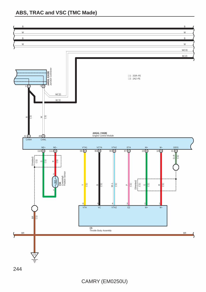
244
CAMRY (EM0250U)
ABS, TRAC and VSC (TMC Made)
B
W
CANH CANL
W
7 A1 A
49 A
B
41 A
( ∗1)
( ∗1)
Junc
tion
Con
nect
orA4
0(A)
, E41
( B)
Cra
nksh
aft
Pos
ition
Sen
sor
C5
C50
110
( Shi
elde
d)
RG
NE+
B
NE–
B
1
2
111
BR
Engine Control ModuleA55(A), C55(B)
G–R
19 B B18 B41
W–LB P
( Shi
elde
d)
Y
VTA1 ETAVCTA M+ M– GE01
99 B98 B 97 BB96
RGVTA2
Throttle Body AssemblyC5
123456
VTA VC VTA2 E2 M+ M–
W
B
∗ 1 : 2GR–FE∗ 2 : 2AZ–FE
W(∗2)
B(∗2)
( ∗1)
( ∗1)
( ∗1)
( ∗1)
( ∗1)
( ∗1)
( ∗1)
( ∗1)
( ∗1)
( ∗1)
( ∗1)
( ∗1)
B
W
B
W
W(∗2)
B(∗2)
BR BR

CAMRY (EM0250U)
245
Eng
ine
Con
trol M
odul
eA5
5(A)
, C55
( B)
Tran
smis
sion
Con
trol S
W
Junc
tion
Con
nect
orJu
nctio
n C
onne
ctor
C57
A41(
A), A
42( B
)
BR
W–B
GR
10 3H
10 3D
15 EA1
17 A
18 B
4 CA3
3
C7
5 3C
5 3L
O
7. 5AECU IGNO. 2
A
S
25A
SFTD
51A
SFTU
16
E
10
IG
BR
BR
W–B
YLR
AE5 AE520 AE5
E31
OYLG
(IG)
19 IF
1 7
5
2
SFTU SFTD S
3
11
4A11
4C12
Par
k/N
eutra
lP
ositi
on S
W
RO
10 CA2
R
C1(
A)
25 B
R
26 B
D
G
24 27
L–B
B–W
B
N
B
P
P
(IG)
16 IH
10AGAUGENO. 1
14 EA1
R
DLNLRLPL
RB
4D7
4C7
OO
( ∗1)
( ∗1)
(∗1)
(∗1)
( ∗1)
( ∗1)
( ∗1)
( ∗1)
( ∗1)
( ∗1)
( ∗1)
( ∗1)
( ∗1)
( ∗1)
( ∗1)
( ∗1)
( ∗1)
(∗1)
( ∗1)
( ∗1)
( ∗1)
( ∗1)
( ∗1)
( ∗1)
B
W
B
W
W(∗2)
B(∗2)
B
W
B
W
W(∗2)
B(∗2)
BR BR
A1
A3 A2 A8 A7
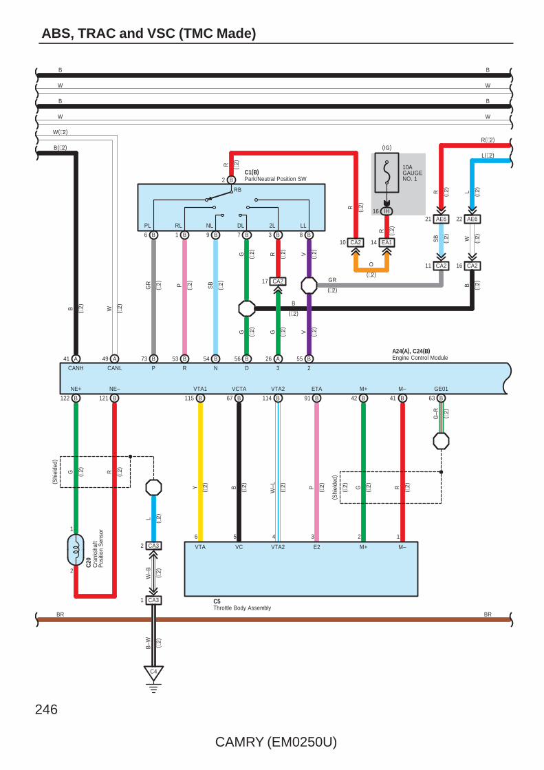
246
CAMRY (EM0250U)
ABS, TRAC and VSC (TMC Made)
CANH CANL
W
49 A
B
41 A
( ∗2)
( ∗2)
G–R
42 B B41 B63
W–LB P
( Shi
elde
d)
Y
VTA1 ETAVCTA M+ M– GE01
114 B115 B 91 BB67RG
VTA2
Throttle Body AssemblyC5
123456
VTA VC VTA2 E2 M+ M–
Cra
nksh
aft
Pos
ition
Sen
sor
B–W
W–B
1 CA3
2 CA3
C4
C20
( Shi
elde
d)
NE+ NE–
B122 B121
G R
2
L
1
( ∗2)
( ∗2)
( ∗2)
( ∗2)
( ∗2)
G
GR P SB
DNRP
C1(B)
73 B 53 B B54 56 B
G
CA211
AE621
SB
V
23
26 A 55 B
RB
CA217
RG V
10AGAUGENO. 1
IH16
(IG)
EA114CA210
R
R
R
O
GR
16 CA2
AE622
W
R L
PL RL NL DL 2L LL
Park/Neutral Position SW
Engine Control ModuleA24(A), C24(B)
B
W
B
W
W(∗2)
B(∗2)
B
W
B
W
( ∗2)
( ∗2)
(∗2)
( ∗2)
( ∗2)
( ∗2)
( ∗2)
( ∗2)
( ∗2)
( ∗2)
( ∗2)
( ∗2)
( ∗2)
(∗2)
( ∗2)
( ∗2)
( ∗2)
( ∗2)
R(∗2)
L(∗2)
( ∗2)
( ∗2)
( ∗2)
( ∗2)
( ∗2)
( ∗2)
( ∗2)
( ∗2)
BR BR
B6 B1 B9 B7 B3 B8
B2
B
B
( ∗2)
(∗2)

CAMRY (EM0250U)
247
B
W B
W B
1 B2 B
1 AA2 2 G G1
FE314
W
FE313
NSSLAE516
4
A25
2 1
O L
AT4 NSSDCA215
AE619
O RYYB
RG
6 5
L
B74
E31
Tran
smis
sion
Con
trol S
WATL
Eng
ine
Con
trol M
odul
eA2
4(A)
, C24
( B)
BW
1 E2 E
∗ 2 : 2AZ–FE
B
W
B
W
R(∗2)
L(∗2)
( ∗2)
( ∗2)
( ∗2)
( ∗2)
( ∗2)
( ∗2)
( ∗2)
( ∗2) W B
B
W
B
W
BRBR
E42(
A), E
43( B
) , E4
4(C
) , E4
6(E)
, E62
( G) ,
E63(
H)
Junc
tion
Con
nect
or

248
CAMRY (EM0250U)
ABS, TRAC and VSC (TMC Made)
1
2
4D
W
3
GND
W–B
1
W–B
E2
5
IG
IF19
(IG)
7 4B
O
4B6
3L9
CANH
10
9
1
IG
3
BAT
CANL
9
ESS
2
3H
OW
4D7
5 3C
5 3L
O
2
1 IF
10 ID
1
(BAT)
O
CANH
3
CANL
2
O
10AECU–BNO. 1
7. 5AECU IGNO. 2
E17
E34
4B1
4B2
W–B
W–B
W–B
Ste
erin
g S
enso
r
Yaw
Rat
e S
enso
r
BW
BCANH
E8(C)W
CANL
1 H2 H
2 C C1
Main Body ECU
C6 C5
( Ped
al T
ype)
E33
IM2
1
Y L1
14 IC
19
PKB
A18
( Lev
er T
ype)
Par
king
Bra
ke S
W
Par
king
Bra
ke S
W
Junc
tion
Con
nect
or
E49
BR
W
B
W
B
B
W
BR
E42(
A), E
43( B
) , E4
4(C
) , E4
6(E)
, E62
( G) ,
E63(
H)
Junc
tion
Con
nect
or
B W

CAMRY (EM0250U)
249
3D3
11
W
7. 5AGAUGENO. 2
3P
IG12
3Q9
3G2
A
GR
GR
13
Power SupplyCircuit
2
(BAT)
10ADOME
1
IF7
ID13
3Q1
3L12
A
LG
R
R
2
(BAT)
10AMPX–B
1A
3Q12
3D1
A
IG+
V
1
24 A
Spe
edom
eter
Buzzer MULTI LCD
18 AA17
VS
C
AB
S
Slip
Mas
ter
War
ning
BB2
MICRO COMPUTER
IG2
DRIVE IC
6 AE6
W
(IG)
14 B 12 A
EA12
V
V
SB
3Q7
3U2
F1
W–B
W–B
3Q5
3D10
CA34
C6
15EA1
A17
B18
CA34
C7
3
BR(∗1)
GR(∗2)
GR
W–B
W–B
GR
BR
A41(
A), A
42( B
)
C57
( ∗1)
( ∗1)
( ∗2)
(∗1)
SI ESCANH CANL E2
F1(A), F2(B)
Junc
tion
Con
nect
or
Junc
tion
Con
nect
or
Combination Meter
Bra
ke( E
xcep
t US
A)
BR
AK
E( U
SA
)
IG2
DRIVE IC
BR
W
B
B W
∗ 1 : 2GR–FE∗ 2 : 2AZ–FE
3
+B(DOME)
CANI/F
BR
IG2IG2

250
CAMRY (EM0250U)
ABS, TRAC and VSC (TMC Made)
1. ABS OperationIf the brake pedal is depressed suddenly, the ABS controls the hydraulic pressure of the wheel cylinders for all the fourwheels to automatically avoid wheel locking and ensure the directional and steering stability of the vehicle. If the brake pedalis depressed suddenly, the skid control ECU controls the solenoids in the actuators using the signals from the sensors tomove the brake fluid to the reservoir in order to release the braking pressure applied to the wheel cylinder. If the skid controlECU detects that the fluid pressure in the wheel cylinder is insufficient, the ECU controls the solenoids in the actuators toincrease the braking pressure.
2. Traction Control OperationThe traction control system controls the engine torque, the hydraulic pressure of the driving wheel cylinders, slipping of thewheels which may occur at start or acceleration of the vehicle, to ensure an optimal driving power and vehicle stabilitycorresponding to the road conditions.
3. VSC OperationUnexpected road conditions, vehicle speed, emergency situation, and any other external factors may cause large under– orover–steering of the vehicle. If this occurs, the VSC system automatically controls the engine power and wheel brakes toreduce the under– or over–steering.To reduce large over–steering :If the VSC system determines that the over–steering is large, it activates the brakes for the outer turning wheels dependingon the degree of the over–steering to produce the moment toward the outside of the vehicle and reduce the over–steering.To reduce large under–steering :If the VSC system determines that the under–steering is large, it controls the engine power and activates the rear wheelbrakes to reduce the under–steering.
4. Fail Safe FunctionIf an error occurs in the skid control ECU, sensor signals, and/or actuators, the skid control ECU inhibits the brake actuatorcontrol and inputs the error signal to the engine control module. According to the error signal, the brake actuator turns off thesolenoid and the engine control module rejects any electronically controlled throttle open request from the VSC system. As aresult, the vehicle functions regardless of the ABS, TRAC, and VSC systems.
: Parts Location
Code See Page Code See Page Code See Page
A1448 (2GR–FE) C1 B 54 (2AZ–FE) E40 B 57
A1452 (2AZ–FE)
C550 (2GR–FE) E41 B 57
A18 59C5
54 (2AZ–FE) E42 A 57
A19 59 C20 55 (2AZ–FE) E43 B 57
A24 A 52 (2AZ–FE) C24 B 55 (2AZ–FE) E44 C 57
A2648 (2GR–FE) C50 51 (2GR–FE) E46 E 57
A2652 (2AZ–FE) C55 B 51 (2GR–FE) E49 57
A3548 (2GR–FE) C57 51 (2GR–FE) E62 G 57
A3552 (2AZ–FE) E8 C 56 E63 H 57
A40 A 59 E10 56 F1 A 58
A41 A 59 E13 56 F2 B 58
A42 B 59 E17 56 f1 61
A55 A 49 (2GR–FE) E31 56 g1 61
A58 A 59 E33 56
C1 A 50 (2GR–FE) E34 57
: Relay Blocks
Code See Page Relay Blocks (Relay Block Location)
1 22 Engine Room R/B (Engine Compartment Left)
System Outline

CAMRY (EM0250U)
251
: Junction Block and Wire Harness Connector
Code See Page Junction Block and Wire Harness (Connector Location)
1A 25 Engine Room Main Wire and Engine Room J/B (Engine Compartment Left)
3C
36 Instrument Panel Wire and J/B No.3 (Behind the Combination Meter)
3D
36 Instrument Panel Wire and J/B No.3 (Behind the Combination Meter)
3E
36 Instrument Panel Wire and J/B No.3 (Behind the Combination Meter)3G 36 Instrument Panel Wire and J/B No.3 (Behind the Combination Meter)
3H
36 Instrument Panel Wire and J/B No.3 (Behind the Combination Meter)
3K
3L
3P
36 Instrument Panel No.2 Wire and J/B No.3 (Behind the Combination Meter)3Q 36 Instrument Panel No.2 Wire and J/B No.3 (Behind the Combination Meter)
3U
36 Instrument Panel No.2 Wire and J/B No.3 (Behind the Combination Meter)
4A
42 Instrument Panel Wire and J/B No.4 (Instrument Panel Brace Center)4B
42 Instrument Panel Wire and J/B No.4 (Instrument Panel Brace Center)4C
42 Instrument Panel Wire and J/B No.4 (Instrument Panel Brace Center)
4D
IC30 Engine Room Main Wire and Instrument Panel J/B (Cowl Side Left)
ID30 Engine Room Main Wire and Instrument Panel J/B (Cowl Side Left)
IF 30
Instrument Panel Wire and Instrument Panel J/B (Cowl Side Left)
IG31
Instrument Panel Wire and Instrument Panel J/B (Cowl Side Left)IH31
Instrument Panel Wire and Instrument Panel J/B (Cowl Side Left)
IL30
Instrument Panel Wire and Instrument Panel J/B (Cowl Side Left)
IM30
: Connector Joining Wire Harness and Wire Harness
Code See Page Joining Wire Harness and Wire Harness (Connector Location)
AE2 66 Engine Room Main Wire and Instrument Panel Wire (Right Side of the Instrument Panel J/B)
AE566 Engine Room Main Wire and Instrument Panel Wire (Instrument Panel Right)
AE666 Engine Room Main Wire and Instrument Panel Wire (Instrument Panel Right)
CA264 (2GR–FE)
Engine Wire and Engine Room Main Wire (Inside of the Engine Room R/B and Engine Room J/B)
CA265 (2AZ–FE)
Engine Wire and Engine Room Main Wire (Inside of the Engine Room R/B and Engine Room J/B)
CA364 (2GR–FE)
Engine Wire and Engine Room Main Wire (Inside of the Engine Room R/B and Engine Room J/B)
CA365 (2AZ–FE)
EA1 66 Instrument Panel Wire and Engine Room Main Wire (Left Kick Panel)
FE3 66 Instrument Panel No.2 Wire and Instrument Panel Wire (Instrument Panel Center)
NA1 66 Floor Wire and Engine Room Main Wire (Left Kick Panel)
OA1 66 Floor No.2 Wire and Engine Room Main Wire (Right Kick Panel)
fO1 67 Skid Control Sensor Wire and Floor No.2 Wire (Quarter Wheel House Panel LH)
gN1 67 Skid Control Sensor Wire and Floor Wire (Quarter Wheel House Panel RH)
: Ground Points
Code See Page Ground Points Location
A464 (2GR–FE)
Near the Skid Control ECU with ActuatorA465 (2AZ–FE)
Near the Skid Control ECU with Actuator
A6 66 Right Cowl Side Panel
C4 65 (2AZ–FE) Cylinder Block
C5 64 (2GR–FE) Right Side of the Cylinder Block
C6 65 (2AZ–FE) Cylinder Block
C7 64 (2GR–FE) Left Side of the Cylinder Block
E2 66 Instrument Panel Brace LH
F1 66 Instrument Panel Left
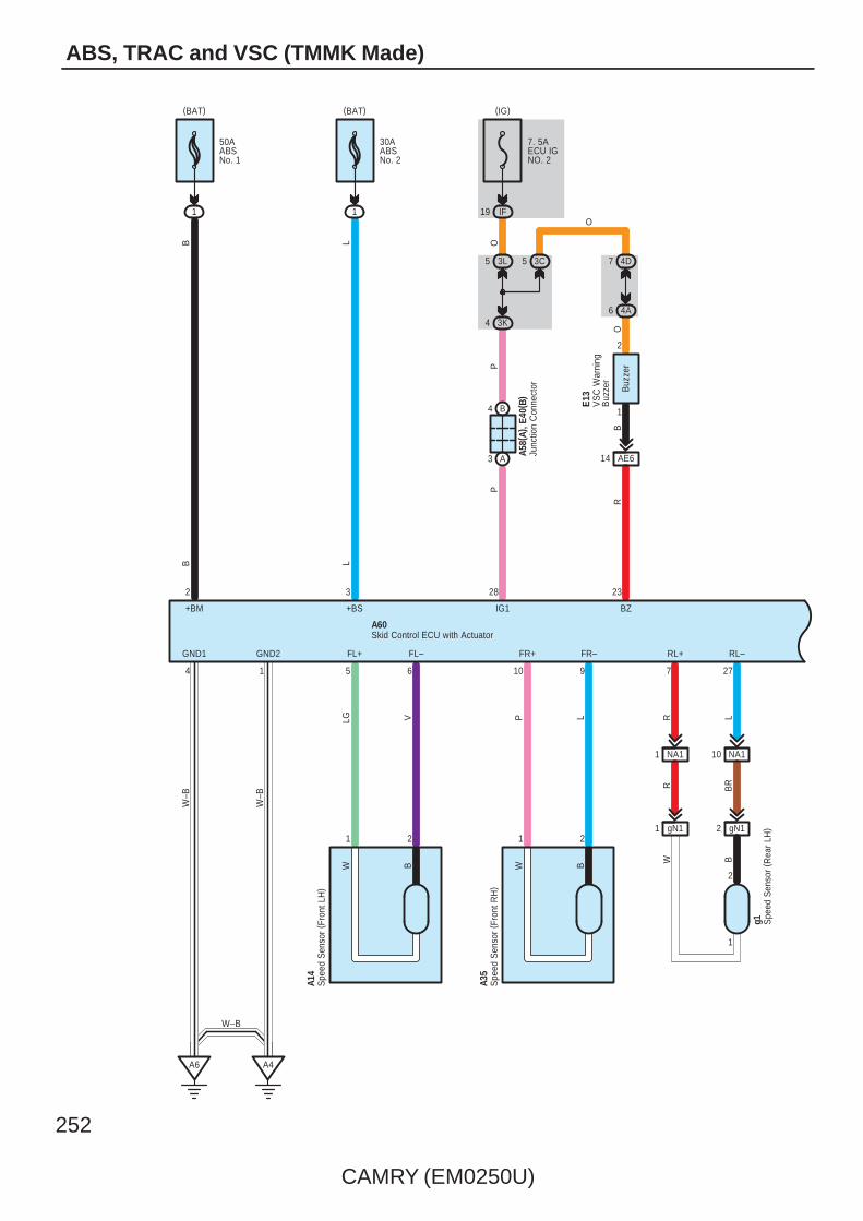
252
CAMRY (EM0250U)
ABS, TRAC and VSC (TMMK Made)
B
21
FR+
9
P
10
L
R BR
RL–
L
7R
27
RL+
A4
BW
1
FL+ FR–
W
2
GND1
4
GND2
1
W–B
W–B
B
1
(BAT)
1
(BAT)
2
+BM
6
LG
5
V
FL–
28
IG1
P
IF19
(IG)
NA11 NA110
B LL
Buz
zer
2
1
3
+BS
23
BZ
A6
E13
50AABSNo. 1
30AABSNo. 2
7. 5AECU IGNO. 2
A14
A35
A60
A58(
A), E
40( B
)
3L5 3C5 4D7
3K44A6
BR
O
PO
O
AE614
B4
A3
Spe
ed S
enso
r ( F
ront
LH
)
Spe
ed S
enso
r ( F
ront
RH
)
Junc
tion
Con
nect
or
Skid Control ECU with Actuator
VS
C W
arni
ngB
uzze
r
gN11 gN12
BW
Spe
ed S
enso
r ( R
ear
LH)
g1
1
2
W–B

CAMRY (EM0250U)
253
B W
RR–
W
29
B
8
RR+
OA11 OA110
fO11 fO12
BW
Spe
ed S
enso
r ( R
ear
RH
)f1
A60Skid Control ECU with Actuator
W
Junc
tion
Con
nect
or
4
O
39
TS
O
P
30
STP1
CANL CANHSP1
BR
33 3514
AE6
6
A40(
A), E
41( B
)
12
4 3E
4 3H
CANH
8 A2 A
4 B 10 B
CANL
B
W
B
B W
14
TS
O
Dat
a Li
nkC
onne
ctor
3
E10
10ASTOP
IC8
(BAT)
B
AE29IL7
IC13
L
L
W
Sto
p La
mp
SW
A19
W
B
BR
1
2
1
2
W B
B W

254
CAMRY (EM0250U)
ABS, TRAC and VSC (TMMK Made)
A40(
A), E
41( B
)
B
W
CANH CANL
W
7 A1 A
Junc
tion
Con
nect
or
49 A
B
41 A
( ∗1)
( ∗1)
Cra
nksh
aft
Pos
ition
Sen
sor
C5
C50
110
( Shi
elde
d)
RG
NE+
B
NE–
B
1
2
111
BR
Engine Control ModuleA55(A), C55(B)
G–R
19 B B18 B41
W–LB P
( Shi
elde
d)
Y
VTA1 ETAVCTA M+ M– GE01
99 B98 B 97 BB96
RGVTA2
Throttle Body AssemblyC5
123456
VTA VC VTA2 E2 M+ M–
W
B
∗ 2 : 2AZ–FE∗ 1 : 2GR–FE
W(∗2)
B(∗2)
( ∗1)
( ∗1)
( ∗1)
( ∗1)
( ∗1)
( ∗1)
( ∗1)
( ∗1)
( ∗1)
( ∗1)
( ∗1)
( ∗1)
B
W
B
W
W(∗2)
B(∗2)
BR BR

CAMRY (EM0250U)
255
Eng
ine
Con
trol M
odul
eA5
5(A)
, C55
( B)
OO
7 4C
7 4D
12 4C
11 4A
11
3
SSFTDSFTU
2
5
71
IF19
(IG)
G L YO
E31
AE520 AE5AE5
R L Y
W–B
BR
BR
IG
10
E
16
SFTU
A 51
SFTD
A 25
S
A
7. 5AECU IGNO. 2
O
3L5
3C5
C7
3
CA34
B18
A17
EA115
3D10
3H10
GR
W–B
BR
A41(
A), A
42( B
)C
57Ju
nctio
n C
onne
ctor
Junc
tion
Con
nect
or
Tran
smis
sion
Con
trol S
W
( ∗1)
( ∗1)
( ∗1)
RB
PL RL NL DL
R
EA114
10AGAUGENO. 1
IH16
(IG)
P
P
B
N
B
B–W L–
B
2724
G
D
B26
R
B25
C1(
A)
R
CA210
OR
Par
k/N
eutra
lP
ositi
on S
W
( ∗1)
( ∗1)
(∗1)
(∗1)
( ∗1)
( ∗1)
( ∗1)
( ∗1)
( ∗1)
( ∗1)
( ∗1)
( ∗1)
( ∗1)
( ∗1)
(∗1)
( ∗1)
( ∗1)
( ∗1)
( ∗1)
( ∗1)
( ∗1)
B
W
B
W
W(∗2)
B(∗2)
B
W
B
W
W(∗2)
B(∗2)
BR BR
A1
A3 A2 A8 A7
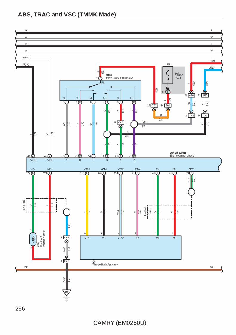
256
CAMRY (EM0250U)
ABS, TRAC and VSC (TMMK Made)
CANH CANL
W
49 A
B
41 A
( ∗2)
( ∗2)
G–R
42 B B41 B63
W–LB P
( Shi
elde
d)
Y
VTA1 ETAVCTA M+ M– GE01
114 B115 B 91 BB67RG
VTA2
Throttle Body AssemblyC5
123456
VTA VC VTA2 E2 M+ M–
Cra
nksh
aft
Pos
ition
Sen
sor
B–W
W–B
1 CA3
2 CA3
C4
C20
( Shi
elde
d)
NE+ NE–
B122 B121
G R
2
L
1
( ∗2)
( ∗2)
( ∗2)
( ∗2)
( ∗2)
G
GR P SB
DNRP
C1(B)
73 B 53 B B54 56 B
G
CA211
AE621
SB
V
23
26 A 55 B
RB
CA217
RG V
10AGAUGENO. 1
IH16
(IG)
EA114CA210
R
R
R
O
GR
16 CA2
AE622
W
R L
PL RL NL DL 2L LL
Park/Neutral Position SW
Engine Control ModuleA24(A), C24(B)
B
W
B
W
W(∗2)
B(∗2)
( ∗2)
B
W
B
W
( ∗2)
(∗2)
( ∗2)
( ∗2)
( ∗2)
( ∗2)
( ∗2)
( ∗2)
( ∗2)
( ∗2)
( ∗2)
( ∗2)
(∗2)
( ∗2)
( ∗2)
( ∗2)
( ∗2)
R(∗2)
L(∗2)
( ∗2)
( ∗2)
( ∗2)
( ∗2)
( ∗2)
( ∗2)
( ∗2)
( ∗2)
BR BR
B6 B1 B9 B7 B3 B8
B2
B
B
( ∗2)
(∗2)
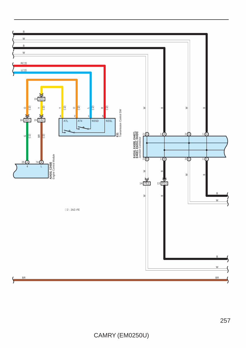
CAMRY (EM0250U)
257
B
W B
W B
1 B2 B
1 AA2 2 G G1
FE314
W
FE313
E2 E1
W B
NSSLAE516
4
A25
2 1
O L
AT4 NSSDCA215
AE619
O RYYB
RG
6 5
L
B74
E31
Tran
smis
sion
Con
trol S
WATL
Eng
ine
Con
trol M
odul
eA2
4(A)
, C24
( B)
∗ 2 : 2AZ–FE
B
W
B
W
R(∗2)
L(∗2)
( ∗2)
( ∗2)
( ∗2)
( ∗2)
( ∗2)
( ∗2)
( ∗2)
( ∗2) W B
B
W
B
W
BRBR
E42(
A), E
43( B
) , E4
4(C
) , E4
6(E)
, E62
( G) ,
E63(
H)
Junc
tion
Con
nect
or
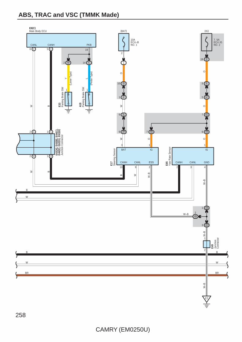
258
CAMRY (EM0250U)
ABS, TRAC and VSC (TMMK Made)
5 C
1
2
4D
W
3
GND
W–B
4
W–B
E2
1
IG
IF19
(IG)
7 4B
O
4B6
3L9
CANH
10
9
1
IG
3
BAT
CANL
9
ESS
2
3H
OW
4D7
5 3C
5 3L
O
2
1 IF
10 ID
1
(BAT)
O
CANH
2
CANL
3
O
10AECU–BNO. 1
7. 5AECU IGNO. 2
E17
E65
4B1
4B2
W–B
W–B
W–B
Ste
erin
g S
enso
r
Yaw
Rat
e S
enso
r
Junc
tion
Con
nect
or
BC6
W
BCANH
E8(C)W
CANL
1 H2 H
2 C C1
Main Body ECU
E49
( Ped
al T
ype)
E33
IM2
1
Y L1
14 IC
19
PKB
A18
( Lev
er T
ype)
Par
king
Bra
ke S
W
Par
king
Bra
ke S
W
BR
W
B
W
B
B
W
BR
E42(
A), E
43( B
) , E4
4(C
) , E4
6(E)
, E62
( G) ,
E63(
H)
Junc
tion
Con
nect
or
B W
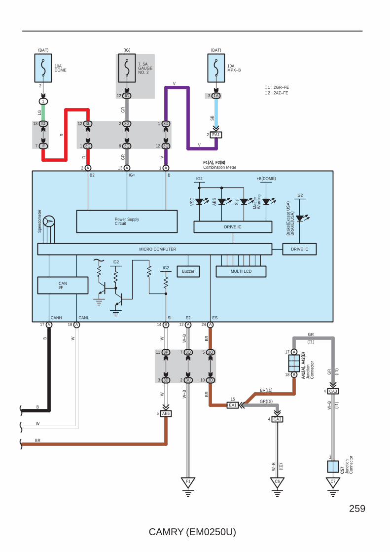
CAMRY (EM0250U)
259
3D3
11
W
7. 5AGAUGENO. 2
3P
IG12
3Q9
3G2
A
GR
GR
13
Power SupplyCircuit
2
(BAT)
10ADOME
1
IF7
ID13
3Q1
3L12
A
LG
R
R
2
(BAT)
10AMPX–B
1A
3Q12
3D1
A
IG+
V
1
24 A
Spe
edom
eter
Buzzer MULTI LCD
18 AA17
VS
C
AB
S
Slip
Mas
ter
War
ning
BB2
MICRO COMPUTER
IG2
DRIVE IC
6 AE6
W
(IG)
14 B 12 A
EA12
V
V
SB
3Q7
3U2
F1
W–B
W–B
3Q5
3D10
CA34
C6
15EA1
A17
B18
CA34
C7
3
BR(∗1)
GR(∗2)
GR
W–B
W–B
GR
BR
A41(
A), A
42( B
)
C57
( ∗1)
( ∗1)
( ∗2)
(∗1)
SI ESCANH CANL E2
F1(A), F2(B)
Junc
tion
Con
nect
or
Junc
tion
Con
nect
or
Combination Meter
Bra
ke( E
xcep
t US
A)
BR
AK
E( U
SA
)
IG2
DRIVE IC
BR
W
B
B W
∗ 2 : 2AZ–FE∗ 1 : 2GR–FE
3
+B(DOME)
BR
CANI/F
IG2IG2

260
CAMRY (EM0250U)
ABS, TRAC and VSC (TMMK Made)
1. ABS OperationIf the brake pedal is depressed suddenly, the ABS controls the hydraulic pressure of the wheel cylinders for all the fourwheels to automatically avoid wheel locking and ensure the directional and steering stability of the vehicle. If the brake pedalis depressed suddenly, the skid control ECU controls the solenoids in the actuators using the signals from the sensors tomove the brake fluid to the reservoir in order to release the braking pressure applied to the wheel cylinder. If the skid controlECU detects that the fluid pressure in the wheel cylinder is insufficient, the ECU controls the solenoids in the actuators toincrease the braking pressure.
2. Traction Control OperationThe traction control system controls the engine torque, the hydraulic pressure of the driving wheel cylinders, slipping of thewheels which may occur at start or acceleration of the vehicle, to ensure an optimal driving power and vehicle stabilitycorresponding to the road conditions.
3. VSC OperationUnexpected road conditions, vehicle speed, emergency situation, and any other external factors may cause large under– orover–steering of the vehicle. If this occurs, the VSC system automatically controls the engine power and wheel brakes toreduce the under– or over–steering.To reduce large over–steering :If the VSC system determines that the over–steering is large, it activates the brakes for the outer turning wheels dependingon the degree of the over–steering to produce the moment toward the outside of the vehicle and reduce the over–steering.To reduce large under–steering :If the VSC system determines that the under–steering is large, it controls the engine power and activates the rear wheelbrakes to reduce the under–steering.
4. Fail Safe FunctionIf an error occurs in the skid control ECU, sensor signals, and/or actuators, the skid control ECU inhibits the brake actuatorcontrol and inputs the error signal to the engine control module. According to the error signal, the brake actuator turns off thesolenoid and the engine control module rejects any electronically controlled throttle open request from the VSC system. As aresult, the vehicle functions regardless of the ABS, TRAC, and VSC systems.
: Parts Location
Code See Page Code See Page Code See Page
A1448 (2GR–FE) C1 B 54 (2AZ–FE) E41 B 57
A1452 (2AZ–FE)
C550 (2GR–FE) E42 A 57
A18 59C5
54 (2AZ–FE) E43 B 57
A19 59 C20 55 (2AZ–FE) E44 C 57
A24 A 52 (2AZ–FE) C24 B 55 (2AZ–FE) E46 E 57
A3548 (2GR–FE) C50 51 (2GR–FE) E49 57
A3552 (2AZ–FE) C55 B 51 (2GR–FE) E62 G 57
A40 A 59 C57 51 (2GR–FE) E63 H 57
A41 A 59 E8 C 56 E65 57
A42 B 59 E10 56 F1 A 58
A55 A 49 (2GR–FE) E13 56 F2 B 58
A58 A 59 E17 56 f1 61
A6049 (2GR–FE) E31 56 g1 61
A6053 (2AZ–FE) E33 56
C1 A 50 (2GR–FE) E40 B 57
: Relay Blocks
Code See Page Relay Blocks (Relay Block Location)
1 22 Engine Room R/B (Engine Compartment Left)
System Outline

CAMRY (EM0250U)
261
: Junction Block and Wire Harness Connector
Code See Page Junction Block and Wire Harness (Connector Location)
1A 25 Engine Room Main Wire and Engine Room J/B (Engine Compartment Left)
3C
36 Instrument Panel Wire and J/B No.3 (Behind the Combination Meter)
3D
36 Instrument Panel Wire and J/B No.3 (Behind the Combination Meter)
3E
36 Instrument Panel Wire and J/B No.3 (Behind the Combination Meter)3G 36 Instrument Panel Wire and J/B No.3 (Behind the Combination Meter)
3H
36 Instrument Panel Wire and J/B No.3 (Behind the Combination Meter)
3K
3L
3P
36 Instrument Panel No.2 Wire and J/B No.3 (Behind the Combination Meter)3Q 36 Instrument Panel No.2 Wire and J/B No.3 (Behind the Combination Meter)
3U
36 Instrument Panel No.2 Wire and J/B No.3 (Behind the Combination Meter)
4A
42 Instrument Panel Wire and J/B No.4 (Instrument Panel Brace Center)4B
42 Instrument Panel Wire and J/B No.4 (Instrument Panel Brace Center)4C
42 Instrument Panel Wire and J/B No.4 (Instrument Panel Brace Center)
4D
IC30 Engine Room Main Wire and Instrument Panel J/B (Cowl Side Left)
ID30 Engine Room Main Wire and Instrument Panel J/B (Cowl Side Left)
IF 30
Instrument Panel Wire and Instrument Panel J/B (Cowl Side Left)
IG31
Instrument Panel Wire and Instrument Panel J/B (Cowl Side Left)IH31
Instrument Panel Wire and Instrument Panel J/B (Cowl Side Left)
IL30
Instrument Panel Wire and Instrument Panel J/B (Cowl Side Left)
IM30
: Connector Joining Wire Harness and Wire Harness
Code See Page Joining Wire Harness and Wire Harness (Connector Location)
AE2 66 Engine Room Main Wire and Instrument Panel Wire (Right Side of the Instrument Panel J/B)
AE566 Engine Room Main Wire and Instrument Panel Wire (Instrument Panel Right)
AE666 Engine Room Main Wire and Instrument Panel Wire (Instrument Panel Right)
CA264 (2GR–FE)
Engine Wire and Engine Room Main Wire (Inside of the Engine Room R/B and Engine Room J/B)
CA265 (2AZ–FE)
Engine Wire and Engine Room Main Wire (Inside of the Engine Room R/B and Engine Room J/B)
CA364 (2GR–FE)
Engine Wire and Engine Room Main Wire (Inside of the Engine Room R/B and Engine Room J/B)
CA365 (2AZ–FE)
EA1 66 Instrument Panel Wire and Engine Room Main Wire (Left Kick Panel)
FE3 66 Instrument Panel No.2 Wire and Instrument Panel Wire (Instrument Panel Center)
NA1 66 Floor Wire and Engine Room Main Wire (Left Kick Panel)
OA1 66 Floor No.2 Wire and Engine Room Main Wire (Right Kick Panel)
fO1 67 Skid Control Sensor Wire and Floor No.2 Wire (Quarter Wheel House Panel LH)
gN1 67 Skid Control Sensor Wire and Floor Wire (Quarter Wheel House Panel RH)
: Ground Points
Code See Page Ground Points Location
A464 (2GR–FE)
Near the Skid Control ECU with ActuatorA465 (2AZ–FE)
Near the Skid Control ECU with Actuator
A6 66 Right Cowl Side Panel
C4 65 (2AZ–FE) Cylinder Block
C5 64 (2GR–FE) Right Side of the Cylinder Block
C6 65 (2AZ–FE) Cylinder Block
C7 64 (2GR–FE) Left Side of the Cylinder Block
E2 66 Instrument Panel Brace LH
F1 66 Instrument Panel Left
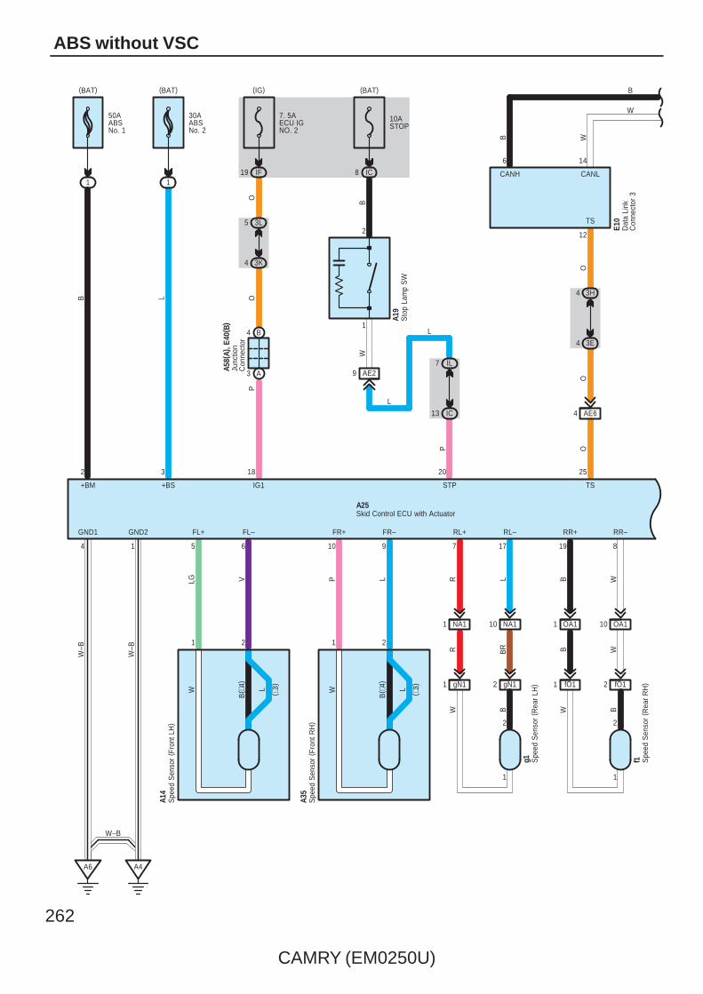
262
CAMRY (EM0250U)
ABS without VSC
B( ∗
4)
21
FR+
9
P
10
L
B WR BR
RL–
L
7
R
17
RR–RL+
A4
B( ∗
4)
W
1
FL+ FR–
W
19
B
W
2
8
RR+GND1
4
GND2
1
W–B
W–B
B
1
(BAT)
L
1
(BAT)
2 3
+BM +BS
6
LG
5
V
FL–
OO
18
IG1
P
IF19
(IG)
NA11 NA110 OA11 OA110
A6
A14
A35
A25
50AABSNo. 1
30AABSNo. 2
7. 5AECU IGNO. 2
A58(
A), E
40( B
)3L5
3K4
B4
A3
Spe
ed S
enso
r ( F
ront
LH
)
Skid Control ECU with Actuator
Spe
ed S
enso
r ( F
ront
RH
)
Junc
tion
Con
nect
or
f1 Spe
ed S
enso
r ( R
ear
RH
)
g1 Spe
ed S
enso
r ( R
ear
LH)
W W BB
2 fO11 fO12 gN11 gN1
L ( ∗3)L ( ∗3)
W
4
O
25
TS
O
P
20
STP
AE6
6
12
4 3E
4 3H
CANH CANL
B
14
TS
O
Dat
a Li
nkC
onne
ctor
3
E10
10ASTOP
IC8
(BAT)
B
AE29IL7
IC13
L
L
W
Sto
p La
mp
SW
A19
W
B
1 1
2 2
1
2
W–B

CAMRY (EM0250U)
263
SP1
BR
23
∗ 2 : 2AZ–FE∗ 1 : 2GR–FE
A40(
A), E
41( B
)
7 A1 A8 A2 A
4 B 10 B
Junc
tion
Con
nect
or
B
W
B W
B–W L–
B
W
B
W(∗2)
B(∗2)
( ∗1)
( ∗1)
BR
NLPL
N
P
RB
Par
k/N
eutra
lP
ositi
on S
W
C1(
A)
R ( ∗1)
CANH CANL
W
49 A
B
41 A
( ∗1)
( ∗1)
Cra
nksh
aft
Pos
ition
Sen
sor
C5
C50
110
( Shi
elde
d)
RG
NE+
B
NE–
B
1
2
111
BR
R
EA114
10AGAUGENO. 1
IH16
(IG)
P
B
N
B2724
CA210
O
R
Engine Control ModuleA55(A), C55(B)
G–R
19 B B18 B41
W–LB P
( Shi
elde
d)
Y
VTA1 ETAVCTA M+ M– GE01
99 B98 B 97 BB96
RGVTA2
Throttle Body AssemblyC5
123456
VTA VC VTA2 E2 M+ M–
( ∗1)
( ∗1)
( ∗1)
( ∗1)
( ∗1)
( ∗1)
( ∗1)
( ∗1)
( ∗1)
( ∗1)
( ∗1)
( ∗1)
( ∗1)
( ∗1)
(∗1)
A1
A3 A8
W(∗2)
B(∗2)
WB
15
CANL
26
CANH
W
B
Ski
d C
ontro
l EC
Uw
ith A
ctua
tor
A25
∗ 3 : TMC Made∗ 4 : TMMK MadeB W
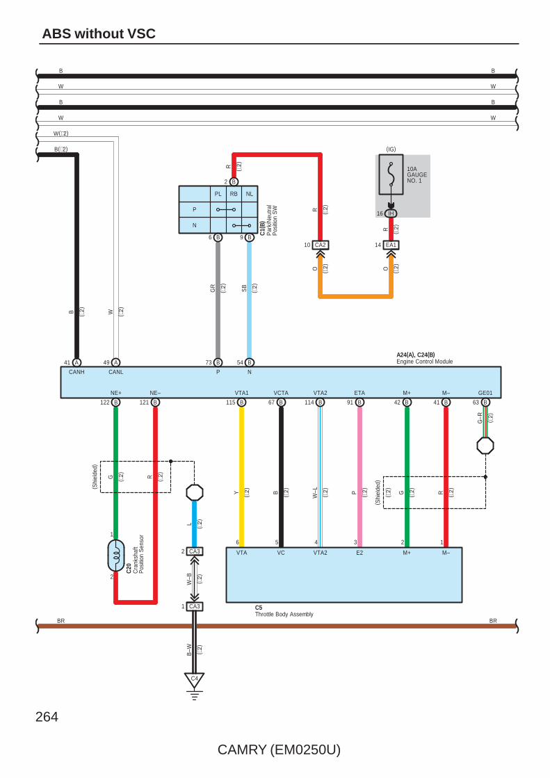
264
CAMRY (EM0250U)
ABS without VSC
CANH CANL
W
49 A
B
41 A
( ∗2)
( ∗2)
GR
SB
NP
73 B B54
10AGAUGENO. 1
IH16
(IG)
EA114CA210
R
R
R
Engine Control ModuleA24(A), C24(B)
B
W
B
W
W(∗2)
B(∗2)
( ∗2)
B
W
B
W
( ∗2)
( ∗2)
( ∗2)
( ∗2)
BR BR
G–R
42 B B41 B63
W–LB P
( Shi
elde
d)
Y
VTA1 ETAVCTA M+ M– GE01
114 B115 B 91 BB67
RGVTA2
Throttle Body AssemblyC5
123456
VTA VC VTA2 E2 M+ M–
Cra
nksh
aft
Pos
ition
Sen
sor
B–W
W–B
1 CA3
2 CA3
C4
C20
( Shi
elde
d)
NE+ NE–
B122 B121
G R
2
L
1
( ∗2)
( ∗2)
( ∗2)
( ∗2)
( ∗2)
( ∗2)
( ∗2)
( ∗2)
( ∗2)
( ∗2)
( ∗2)
( ∗2)
( ∗2)
NLPL
N
P
RB
Par
k/N
eutra
lP
ositi
on S
W
C1(
B)
B6 B9
B2
O ( ∗2)O ( ∗2)
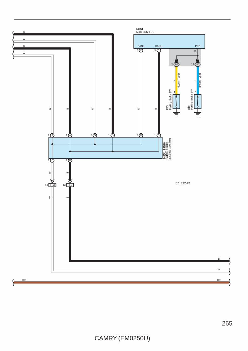
CAMRY (EM0250U)
265
5 C
B
W B
C6
W B B
CANH
E8(C)
W
CANL
1 B2 B
2 C C11 AA2 2 G G1
W
Main Body ECU
( Ped
al T
ype)
E33
IM2
1
Y L
1
14 IC
19
PKB
A18
( Lev
er T
ype)
Par
king
Bra
ke S
W
Par
king
Bra
ke S
W
B
W
B
WW B
B
W
BRBR
E42(
A), E
43( B
) , E4
4(C
) , E6
2(G
)Ju
nctio
n C
onne
ctor
∗ 2 : 2AZ–FE14 FE3 13 FE3

266
CAMRY (EM0250U)
ABS without VSC
3D3
11
W
7. 5AGAUGENO. 2
3P
IG12
3Q9
3G2
A
GR
GR
13
Power SupplyCircuit
2
(BAT)
10ADOME
1
IF7
ID13
3Q1
3L12
A
LG
R
R
2
(BAT)
10AMPX–B
3Q12
3D1
A
IG+
V1
24 A
Spe
edom
eter
18 AA17
AB
S
BB2IG2
DRIVE IC
6 AE6
W
(IG)
14 B 12 A
EA12
V
V
SB
3Q7
3U2
F1
W–B
W–B
3Q5
3D10
CA34
C6
15EA1
A17
B18
CA34
C7
3
BR(∗1)
GR(∗2)
GR
W–B
W–B
GR
BR
A41(
A), A
42( B
)
C57
( ∗1)
( ∗1)
( ∗2)
(∗1)
SI ESCANH CANL E2
F1(A), F2(B)
MICRO COMPUTER
Junc
tion
Con
nect
or
Junc
tion
Con
nect
or
Combination Meter
Bra
ke( E
xcep
t US
A)
BR
AK
E( U
SA
)
IG2
DRIVE IC
BR
W
B
B W
∗ 2 : 2AZ–FE∗ 1 : 2GR–FE
1A3
CANI/F
IG2IG2
BR

CAMRY (EM0250U)
267
∗ ABS systemThis system controls the respective brake fluid pressures acting on the disc brake cylinders of the right front wheel, left frontwheel and rear wheels when the brakes are applied in a panic stop so that the wheels do not lock. This results in improveddirectional stability and steerability during panic braking.∗ Front and rear braking force distribution systemUsing the hydraulic controlling device, this system distributes the braking force to the front and rear wheel in appropriatelyaccording to the running condition of the vehicle.
1. Input Signals(1) Speed sensor signal
The speed of the wheels is detected and input to TERMINALS 5, 7, 10 and 19 of the skid control ECU with actuator.(2) Stop light SW signal
A signal is input to TERMINAL 20 of the skid control ECU with actuator when the brake pedal is depressed.
2. System OperationDuring sudden braking the skid control ECU with actuator has signals input from each sensor, which controls the current tothe solenoid inside the actuator and lets the hydraulic pressure acting on each wheel cylinder escape to the reservoir. Thepump inside the actuator is also operating at this time and it returns the brake fluid from the reservoir to the master cylinder,thus preventing locking of the vehicle wheels.If the skid control ECU with actuator judges that the hydraulic pressure acting on the wheel cylinder is insufficient, the currenton the solenoid is controlled and the hydraulic pressure is increased. Holding of the hydraulic pressure is also controlled bythe skid control ECU with actuator, by the same method as above. Pressure reduction, holding and increase are repeated tomaintain vehicle stability and to improve steerability during sudden braking.
: Parts Location
Code See Page Code See Page Code See Page
A1448 (2GR–FE) A55 A 49 (2GR–FE) E10 56
A1452 (2AZ–FE) A58 A 59 E33 56
A18 59C1
A 50 (2GR–FE) E40 B 57
A19 59C1
B 54 (2AZ–FE) E41 B 57
A24 A 52 (2AZ–FE)C5
50 (2GR–FE) E42 A 57
A2548 (2GR–FE)
C554 (2AZ–FE) E43 B 57
A2552 (2AZ–FE) C20 55 (2AZ–FE) E44 C 57
A3548 (2GR–FE) C24 B 55 (2AZ–FE) E62 G 57
A3552 (2AZ–FE) C50 51 (2GR–FE) F1 A 58
A40 A 59 C55 B 51 (2GR–FE) F2 B 58
A41 A 59 C57 51 (2GR–FE) f1 61
A42 B 59 E8 C 56 g1 61
: Relay Blocks
Code See Page Relay Blocks (Relay Block Location)
1 22 Engine Room R/B (Engine Compartment Left)
System Outline

268
CAMRY (EM0250U)
ABS without VSC
: Junction Block and Wire Harness Connector
Code See Page Junction Block and Wire Harness (Connector Location)
1A 25 Engine Room Main Wire and Engine Room J/B (Engine Compartment Left)
3D
36 Instrument Panel Wire and J/B No.3 (Behind the Combination Meter)
3E
36 Instrument Panel Wire and J/B No.3 (Behind the Combination Meter)3G
36 Instrument Panel Wire and J/B No.3 (Behind the Combination Meter)3H
36 Instrument Panel Wire and J/B No.3 (Behind the Combination Meter)
3K
3L
3P
36 Instrument Panel No.2 Wire and J/B No.3 (Behind the Combination Meter)3Q 36 Instrument Panel No.2 Wire and J/B No.3 (Behind the Combination Meter)
3U
36 Instrument Panel No.2 Wire and J/B No.3 (Behind the Combination Meter)
IC30 Engine Room Main Wire and Instrument Panel J/B (Cowl Side Left)
ID30 Engine Room Main Wire and Instrument Panel J/B (Cowl Side Left)
IF 30
Instrument Panel Wire and Instrument Panel J/B (Cowl Side Left)
IG31
Instrument Panel Wire and Instrument Panel J/B (Cowl Side Left)IH31
Instrument Panel Wire and Instrument Panel J/B (Cowl Side Left)
IL30
Instrument Panel Wire and Instrument Panel J/B (Cowl Side Left)
IM30
: Connector Joining Wire Harness and Wire Harness
Code See Page Joining Wire Harness and Wire Harness (Connector Location)
AE2 66 Engine Room Main Wire and Instrument Panel Wire (Right Side of the Instrument Panel J/B)
AE6 66 Engine Room Main Wire and Instrument Panel Wire (Instrument Panel Right)
CA264 (2GR–FE)
Engine Wire and Engine Room Main Wire (Inside of the Engine Room R/B and Engine Room J/B)
CA265 (2AZ–FE)
Engine Wire and Engine Room Main Wire (Inside of the Engine Room R/B and Engine Room J/B)
CA364 (2GR–FE)
Engine Wire and Engine Room Main Wire (Inside of the Engine Room R/B and Engine Room J/B)
CA365 (2AZ–FE)
EA1 66 Instrument Panel Wire and Engine Room Main Wire (Left Kick Panel)
FE3 66 Instrument Panel No.2 Wire and Instrument Panel Wire (Instrument Panel Center)
NA1 66 Floor Wire and Engine Room Main Wire (Left Kick Panel)
OA1 66 Floor No.2 Wire and Engine Room Main Wire (Right Kick Panel)
fO1 67 Skid Control Sensor Wire and Floor No.2 Wire (Quarter Wheel House Panel LH)
gN1 67 Skid Control Sensor Wire and Floor Wire (Quarter Wheel House Panel RH)
: Ground Points
Code See Page Ground Points Location
A464 (2GR–FE)
Near the Skid Control ECU with ActuatorA465 (2AZ–FE)
Near the Skid Control ECU with Actuator
A6 66 Right Cowl Side Panel
C4 65 (2AZ–FE) Cylinder Block
C5 64 (2GR–FE) Right Side of the Cylinder Block
C6 65 (2AZ–FE) Cylinder Block
C7 64 (2GR–FE) Left Side of the Cylinder Block
F1 66 Instrument Panel Left

CAMRY (EM0250U)
269
Memo
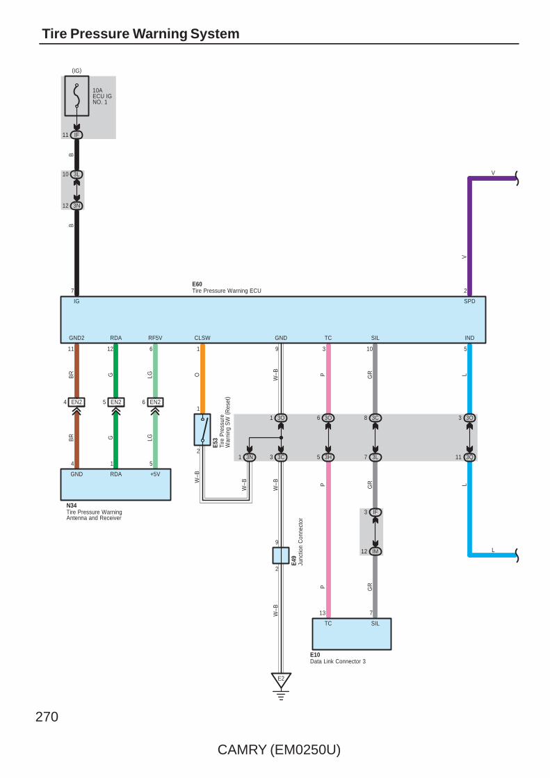
270
CAMRY (EM0250U)
Tire Pressure Warning System
10AECU IGNO. 1
IF11
(IG)
3L10
3N12
BB
IG
7
EN24 EN25 EN26
3O1
3C3
W–B
E2
BR G LG P GR L
BR G LG
W–B
GND2 RDA RF5V GND TC SIL IND
11 12 6 9 3 10 5
GND RDA +5V
E60
N34
3O3
3Q11L
2
1
O
CLSW
1
E53
3N1
W–B
W–B
2
9
E49
W–B
Junc
tion
Con
nect
or
Tire
Pre
ssur
eW
arni
ng S
W (
Res
et)
Tire Pressure Warning ECU
Tire Pressure WarningAntenna and Receiver
L
2
SPD
V
V
3C8
3L7
IF3
IM12
3O6
3H5
GR
GRP
P
713
SILTC
Data Link Connector 3E10
4 1 5

CAMRY (EM0250U)
271
BB2
E2
W–B
W–B
GR
BR
A41(
A), A
42( B
)
C57
( ∗1)
( ∗1)
( ∗2)
(∗1)
IG2
(IG)
12 A
EA12
SB
3Q7
3U2
F1
W–B
W–B
3Q5
3D10
CA34
C6
15EA1
GR(∗2)
A17
B18
CA34BR(∗1)
C7
GR
3
V
F1( A
) , F2
( B)
∗ 2 : 2AZ–FE∗ 1 : 2GR–FE
A24
1
V
IG+
A
1 3D
12 3Q
1A
10A
MP
X–B
(BAT)
2
RLG
7. 5
AG
AU
GE
NO
. 2
IG12
3Q9
3G2
A
GR
GR
13
Power SupplyCircuit
2
(BAT)
10A
DO
ME
12
1
IF7
ID13
3Q
A
1
3L
A7
Tire
Pre
ssur
e
TIRE
R
L
Junc
tion
Con
nect
or
Junc
tion
Con
nect
or
Com
bina
tion
Met
er
L
8 C (∗5)(∗4)B8(∗3)A19
C19B29A5
C17B27A6
C7B7A20
C9B9A17
C10B10A3
C6B6A4
C5B5A18
Speed Sensors
LG V P L R L B W
(∗3)A12(∗4)B33(∗5)C23
FL+ FL– FR+ FR– RL+ RL– RR+ RR–
SP1
IG2
14 B
SI
3P11
3D3
AE66
WW
BR
W
V
10 3O
+S
3 3P
V
B12
IG2
Ski
d C
ontro
l EC
U w
ith A
ctua
tor
A25(
C) ,
A26(
A), A
60( B
)
V
MICRO COMPUTER
ES
BR
∗ 3 : w/ VSC TMC Made∗ 4 : w/ VSC TMMK Made∗ 5 : w/o VSC
3
Spe
edom
eter

272
CAMRY (EM0250U)
Tire Pressure Warning System
: Parts Location
Code See Page Code See Page Code See Page
A25 C48 (2GR–FE)
A60 B49 (2GR–FE) E60 57
A25 C52 (2AZ–FE)
A60 B53 (2AZ–FE) F1 A 58
A26 A48 (2GR–FE) C57 51 (2GR–FE) F2 B 58
A26 A52 (2AZ–FE) E10 56 N34 60
A41 A 59 E49 57
A42 B 59 E53 57
: Relay Blocks
Code See Page Relay Blocks (Relay Block Location)
1 22 Engine Room R/B (Engine Compartment Left)
: Junction Block and Wire Harness Connector
Code See Page Junction Block and Wire Harness (Connector Location)
1A 25 Engine Room Main Wire and Engine Room J/B (Engine Compartment Left)
3C
36 Instrument Panel Wire and J/B No.3 (Behind the Combination Meter)
3D
36 Instrument Panel Wire and J/B No.3 (Behind the Combination Meter)
3G
36 Instrument Panel Wire and J/B No.3 (Behind the Combination Meter)3H 36 Instrument Panel Wire and J/B No.3 (Behind the Combination Meter)
3L
36 Instrument Panel Wire and J/B No.3 (Behind the Combination Meter)
3N
3O
3P
36 Instrument Panel No.2 Wire and J/B No.3 (Behind the Combination Meter)3Q 36 Instrument Panel No.2 Wire and J/B No.3 (Behind the Combination Meter)
3U
36 Instrument Panel No.2 Wire and J/B No.3 (Behind the Combination Meter)
ID 30 Engine Room Main Wire and Instrument Panel J/B (Cowl Side Left)
IF 30
Instrument Panel Wire and Instrument Panel J/B (Cowl Side Left)IG 31 Instrument Panel Wire and Instrument Panel J/B (Cowl Side Left)
IM 30
Instrument Panel Wire and Instrument Panel J/B (Cowl Side Left)
: Connector Joining Wire Harness and Wire Harness
Code See Page Joining Wire Harness and Wire Harness (Connector Location)
AE6 66 Engine Room Main Wire and Instrument Panel Wire (Instrument Panel Right)
CA364 (2GR–FE)
Engine Wire and Engine Room Main Wire (Inside of the Engine Room R/B and Engine Room J/B)CA365 (2AZ–FE)
Engine Wire and Engine Room Main Wire (Inside of the Engine Room R/B and Engine Room J/B)
EA1 66 Instrument Panel Wire and Engine Room Main Wire (Left Kick Panel)
EN2 66 Instrument Panel Wire and Floor Wire (Left Kick Panel)
: Ground Points
Code See Page Ground Points Location
C6 65 (2AZ–FE) Cylinder Block
C7 64 (2GR–FE) Left Side of the Cylinder Block
E2 66 Instrument Panel Brace LH
F1 66 Instrument Panel Left

CAMRY (EM0250U)
273
SRS
NOTICE: When inspecting or repairing the SRS, perform service in accordance with the following precautionary instructionsand the procedure, and precautions in the Repair Manual applicable for the model year.
Malfunction symptoms of the SRS are difficult to confirm, so the DTCs become the most important source of informationwhen troubleshooting. When troubleshooting the SRS, always inspect the DTCs before disconnecting the battery.
Work must be started more than 90 seconds after the ignition SW is turned to the ”LOCK” position (Ignition SWtype) or the power SW is pushed to the ”OFF” position (Power SW type) and the negative (–) terminal cable isdisconnected from the battery.(The SRS is equipped with a back–up power source so that if work is started within 90 seconds fromdisconnecting the negative (–) terminal cable of the battery, the SRS may deploy.)
When the negative (–) terminal cable is disconnected from the battery, the memory of the clock and audio system will becleared. So before starting work, make a record of the contents in the audio memory system. When work is finished,reset the audio systems as they were before and adjust the clock. Some vehicles have power tilt steering, powertelescopic steering, power seat and power outside rear view mirror which are all equipped with memory function.However, it is not possible to make a record of these memory contents. So when the work is finished, it will benecessary to explain it to your customer, and ask the customer to adjust the features and reset the memory. To avoiderasing the memory in each system, never use a back–up power supply from outside the vehicle.
Before repair, remove the airbag sensor if shocks are likely to be applied to the sensor during repair.
Do not expose the following parts directly to hot air or flame;
Even in cases of a minor collision where the SRS does not deploy, the following parts should be inspected;
Never use SRS parts from another vehicle. When replacing parts, replace with new parts.
For the purpose of reuse, never disassemble and repair the following parts.
If the following parts have been dropped, or have cracks, dents and other defects in their case, bracket, and connector,replace with new one.
Use a volt/ohmmeter with high impedance (10 kΩ/V minimum) for troubleshooting electrical circuits of the system.
Information labels are attached to the periphery of the SRS components. Follow the instructions of the notice.
After work on the SRS is completed, check the SRS warning light.
If the vehicle is equipped with a mobile communication system, refer to the precaution in the IN section of the RepairManual.
∗ Steering wheel pad∗ Front passenger airbag assembly∗ Side airbag assembly∗ Curtain shield airbag assembly∗ Knee airbag assembly∗ Seat belt pretensioner∗ Center airbag sensor assembly∗ Front airbag sensor assembly∗ Side airbag sensor assembly∗ Rear airbag sensor assembly
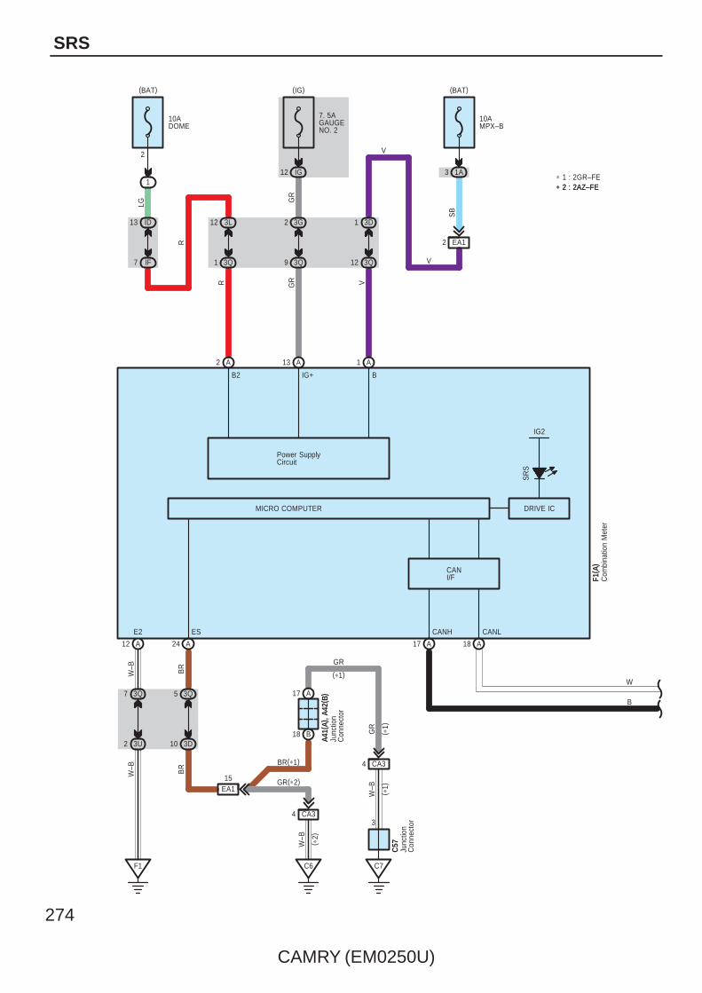
274
CAMRY (EM0250U)
SRS
∗ 1 : 2GR–FE∗ 2 : 2AZ–FE
A
12 3L
1 3Q
13 ID
7 IF
1
10ADOME
(BAT)
2
Power SupplyCircuit
13
GR
GR
A
2 3G
9 3Q
12 IG
7. 5AGAUGENO. 2
LG
R
R
2
(BAT)
10AMPX–B
1A
3Q12
3D1
A
IG+
V1
24 A 18 AA17
SR
S
BB2
MICRO COMPUTER
E2 CANL
W–B
W–B
GR
BR
A41(
A), A
42( B
)
C57
( ∗1)
( ∗1)
( ∗2)
(∗1)
ES CANH
IG2
DRIVE IC
(IG)
12 A
EA12
V
V
SB
3Q7
3U2
F1
W–B
W–B
3Q5
3D10
CA34
C6
15EA1
A17
B18
CA34
C7
3
BR(∗1)
GR(∗2)
GR
F1( A
)
Junc
tion
Con
nect
or
Junc
tion
Con
nect
or
Com
bina
tion
Met
er
B
W
∗ 2 : 2AZ–FE
3
CANI/F
BR

CAMRY (EM0250U)
275
13 22 A
A
A
A
DK+
A
DK–SIL
1 2
DK+ DK–
E54
Y Y–BW
16 109
CANH CANL
Airbag Squib(Knee Airbag)
E30(A), N1(B), O1(C)Airbag Sensor AssemblyCenter
B
W B
WCANL
W
14 6
E10
CANH
BB
1 B2 B
2 G G1
D2 D1
W
E43(
B), E
45( D
) , E6
2(G
)
Data Link Connector 3
Junc
tion
Con
nect
or
W
B
WB
IM12
IE10
7
SIL
GR
IF3
3L7
3C8
GR
GR
GR
FE314 FE313

276
CAMRY (EM0250U)
SRS
D+ D2–D–
ICR+
B
A
–SR+SR
AA
–SL+SL
A
Y–B Y Y–B Y
SpiralCable
G
A13
ICP–
–SL
C
SFP–SFP+
CBY Y–B
Z1
A28
SFD–SFD+
B 7
Y
N21
6B
PD+
7B
PD–
6C
PP+
C
PP– ICD+
B
ICD–
C
ICP+
C
+SL
A
D+
A
D–
A
D2+
A
D2–
A
P+
A
P–
A
P2+
A
P2–
1 2 1 2 1 2 21
1 2 4 3
2 1 2 1
+SR –SR
AE43 AE44 AE42 AE41Y
–B
Y1
E16 c1(A), c2(B)
N8 O8
E30(A), N1(B), O1(C)
Y–B Y Y–B Y
Y–B Y
Y–G
Y–RYY–B
P+
R W BBWRG
9
D2+
ICL+ ICR–
101095412
21347865 30 28 29 27
O1612 21
L+ R+L– R–
P– P2–
ICL–
Y–R
Y–G
Airbag Sensor(Front LH)
Airbag Sensor(Front RH)
Airbag Squib(Steering Wheel Pad)
Airbag Sensor Assembly Center
Airbag Squib(Front Passenger' sAirbag Assembly)
Side AirbagSquib (LH)
Curtain ShieldAirbag Squib (LH)Pretensioner (LH)
Curtain ShieldAirbag Squib (RH)
Side Airbag Squib (RH)
Pretensioner (RH)
Y Y–B Y Y–B
B1 B2 A1 A2
Ec11 Ec12 Ec13 Ec14
Y–G
Y–R
Y–P
Y–G
R
P2+
GRGR
∗ 3 : w/ Power Seat∗ 4 : w/o Power Seat
NZ21 NZ22 OY21 OY22

CAMRY (EM0250U)
277
3 IM
1 IE
BBD+
B
E2
A
BCL+ BCL–
A
PAONP–AB
A
A
E1
BCR+ BCR–
R B
BBD–
B
BBP+
C
BBP–
C
2 1
4 3
1 2
BCL+ BCL–
BCR+ BCR–
BBR–BBR+
BBL–BBL+
IH10
IE6
IH12
IE4
IE5
IF10
E2E1
G R
G RGR
GR
W–B
W–B
W–B
W–B
O7
23178 15
8 11 2526
4
FSP+
C
FSP–
C 8
IG2
A
L
LBE+
C
FSR+ FSR–
2IH
C
LSP+
B
DSP+DBE–
BB
DBE+
LBE–
N3
Seat PositionAirbag Sensor
B
DSP–
1 3 2 4
E30(A), N1(B), O1(C)
BWRG
13141211
10
W–B
2O9
LSP–
14
21 13 12
10AIGN
( ∗3)
( ∗3)Y
B
9 IE
(IG)
A8 A4
B
3R6 3R5
3E8 3D9
R
BR
B ( ∗3)
13
P–AB PAON
F3
Airbag Sensor Assembly Center
Clock
Front Seat Inner Belt (Driver' s Side)
Sid
e A
irbag
Sen
sor
( Fro
nt R
H)
Sid
e A
irbag
Sen
sor
( Rea
r R
H)
O4(C), T10(A), T11(B), d1(D)Occupant Classification ECU
B
(∗3)(∗4)
4 3
Sid
e A
irbag
Sen
sor
( Fro
nt L
H)
N7
Sid
e A
irbag
Sen
sor
( Rea
r LH
)
N12
2 1
1 2
Junc
tion
Con
nect
or
E49
GRGR
B B W W
W B ( ∗4)
( ∗4)
( ∗4)
( ∗4)
( ∗3)
( ∗3)
AIRBAG ON/OFFIndicator
Buckle SW
OT11 OT14
E3
W–B

278
CAMRY (EM0250U)
SRS
BGNDGND
( ∗4)
( ∗3)
A1
W–B
5
BSW
A
A
1
2
EO22
7
3 C
(∗3)(∗4)
W–B
A9 B
SVC2SGD1
B
T17(A), d5(B)
B
DD
SVC4
D
SIG1SVC1
D
B( ∗
3)
R
P( ∗
3)
G OLW
( ∗3)
( ∗3) SVC3 SIG3 SGD3
SIG4
SVC1
BR
GR
GR
O
A
DIA
B
SIG3
B
SGD3
B
SGD4
SIG2
D
SGD2
D
SVC3
SIG1 SGD1 SVC2 SIG2 SGD2
SVC4 SIG4 SGD4
EO24
3
T15(A), d3(B)
T14(A), d2(B) T16(A), d4(B)
O4(C), T10(A), T11(B), d1(D)
VWYGR
∗ 4 : w/o Power Seat∗ 3 : w/ Power Seat
11 7 1 12 8 2
2 5 9 3 6 10 49 C
C
( ∗4)
3
P( ∗
4)
5 C5 A
LG
A
10AECU–BNO. 1
W
9 3L
10 3C
( ∗3)B GR
( ∗3)
( ∗3)
( ∗3)
( ∗3)
LGBR
WBR
O3(B), T7(A)
OW
1 IF
10 ID
2
1
(BAT)
B
W–B
O1
3 EO2
B1B2
+B
C
IG
O( ∗
4)
A7 A1
( ∗4)
BR
C2
3
O20
( A) ,
T18(
B)Ju
nctio
n C
onne
ctor
Occupant Classification ECU
Occupant ClassificationSensor (Front LH)
Occupant ClassificationSensor (Rear LH)
Occupant ClassificationSensor (Front RH)
Occupant ClassificationSensor (Rear RH)
Front Seat Inner Belt(Front Passenger' s Side)
(∗3)B2
(∗3)A3(∗4)B3
(∗3)A3(∗4)B3
A1B1
A2B2
A1
SB
( ∗4)
B1A2B2
B8B12B1B7B11(∗4)
D5 D9 D3 D6 D10 (∗4)D4
R( ∗
4)
B1 B2 (∗4)B3 B1 B2A2
(∗4)B3(∗3)A3A1 A2 (∗3)A3 A1
(∗3)
Junc
tion
Con
nect
or
O21
WB
GR
( ∗3)
OT16 OT15
Buckle SW
OT12
EO210
E3
W–B
(∗3)

CAMRY (EM0250U)
279
∗ The system reaches an ignition judgment to deploy the following device based on the signals received from the frontairbag sensor and deceleration sensor.– Driver Airbag– Front Passenger Airbag– Knee Airbag– Seat Belt Pretensioner
∗ The system reaches an ignition judgment to deploy the following device based on the signals received from the sideairbag sensors.– Side Airbags– Curtain Shield Airbags
∗ The dual–stage SRS airbag system has been used for the driver and front passenger airbags. This system controls theoptimal airbag inflation by judging the extent of impact, seat position (driver seat) and whether or not the seat belt isfastened(driver seat) and infomation from the Front Passenger Occupant Classification System.
∗ The front passenger occupant classification system judges whether the front passenger seat is occupied by an adult orchild (with child seat) or is unoccupied, according to the load applied to the front passenger seat and whether the seat beltis buckled. Based on the results, it restricts the deployment of the front passenger airbag, front passenger side airbag, andfront passenger seat belt pretensioner. In addition, the system informs the driver of the result of the judgment through theuse of the AIRBAG ON/OFF indicator lights.
: Parts Location
Code See Page Code See Page Code See Page
A1348 (2GR–FE)
N362 (*1) T14 A 62 (*1)
A1352 (2AZ–FE)
N363 (*2) T15 A 62 (*1)
A2848 (2GR–FE) N7 60 T16 A 62 (*1)
A2852 (2AZ–FE) N8 60 T17 A 62 (*1)
A41 A 59 N12 60 T18 B 62 (*1)
A42 B 59 N21 60Y1
62 (*1)
C57 51 (2GR–FE) O1 C 59Y1
63 (*2)
E10 56 O3 B 63 (*2)Z1
62 (*1)
E16 56 O4 C 63 (*2)Z1
63 (*2)
E30 A 56 O7 60 c1 A 59
E43 B 57 O8 60 c2 B 59
E45 D 57 O9 60 d1 D 63 (*2)
E49 57 O16 60 d2 B 63 (*2)
E54 57 O20 A 62 (*1) d3 B 63 (*2)
E62 G 57 O21 60 d4 B 63 (*2)
F1 A 58 T7 A 62 (*1) d5 B 63 (*2)
F3 58 T10 A 62 (*1)
N1 B 59 T11 B 62 (*1)
: Relay Blocks
Code See Page Relay Blocks (Relay Block Location)
1 22 Engine Room R/B (Engine Compartment Left)
* 1 : w/ Power Seat * 2 : w/o Power Seat
System Outline

280
CAMRY (EM0250U)
SRS
: Junction Block and Wire Harness Connector
Code See Page Junction Block and Wire Harness (Connector Location)
1A 25 Engine Room Main Wire and Engine Room J/B (Engine Compartment Left)
3C
36 Instrument Panel Wire and J/B No.3 (Behind the Combination Meter)
3D
36 Instrument Panel Wire and J/B No.3 (Behind the Combination Meter)3E 36 Instrument Panel Wire and J/B No.3 (Behind the Combination Meter)
3G
36 Instrument Panel Wire and J/B No.3 (Behind the Combination Meter)
3L
3Q
36 Instrument Panel No.2 Wire and J/B No.3 (Behind the Combination Meter)3R 36 Instrument Panel No.2 Wire and J/B No.3 (Behind the Combination Meter)
3U
36 Instrument Panel No.2 Wire and J/B No.3 (Behind the Combination Meter)
ID 30 Engine Room Main Wire and Instrument Panel J/B (Cowl Side Left)
IE30
Instrument Panel Wire and Instrument Panel J/B (Cowl Side Left)
IF30
Instrument Panel Wire and Instrument Panel J/B (Cowl Side Left)IG31
Instrument Panel Wire and Instrument Panel J/B (Cowl Side Left)
IH31
Instrument Panel Wire and Instrument Panel J/B (Cowl Side Left)
IM 30
: Connector Joining Wire Harness and Wire Harness
Code See Page Joining Wire Harness and Wire Harness (Connector Location)
AE4 66 Engine Room Main Wire and Instrument Panel Wire (Instrument Panel Right)
CA364 (2GR–FE)
Engine Wire and Engine Room Main Wire (Inside of the Engine Room R/B and Engine Room J/B)CA365 (2AZ–FE)
Engine Wire and Engine Room Main Wire (Inside of the Engine Room R/B and Engine Room J/B)
EA1 66 Instrument Panel Wire and Engine Room Main Wire (Left Kick Panel)
EO2 66 Instrument Panel Wire and Floor No.2 Wire (Right Kick Panel)
Ec1 66 Instrument Panel Wire and Instrument Panel Wire Assembly (Behind The Glove Box)
FE3 66 Instrument Panel No.2 Wire and Instrument Panel Wire (Instrument Panel Center)
NZ268 (*1)
Floor Wire and Front Seat Airbag Assembly LH (Under the Driver’s Seat)NZ269 (*2)
Floor Wire and Front Seat Airbag Assembly LH (Under the Driver’s Seat)
OT1 68 (*1) Floor No.2 Wire and Front Seat RH Wire (Under the Front Passenger’s Seat)
OY268 (*1)
Floor No.2 Wire and Front Seat Airbag Assembly RH (Under the Front Passenger’s Seat)OY269 (*2)
Floor No.2 Wire and Front Seat Airbag Assembly RH (Under the Front Passenger’s Seat)
: Ground Points
Code See Page Ground Points Location
C6 65 (2AZ–FE) Cylinder Block
C7 64 (2GR–FE) Left Side of the Cylinder Block
E1 66 Instrument Panel Left
E2 66 Instrument Panel Brace LH
E3 66 Instrument Panel Right
F1 66 Instrument Panel Left
O1 67 Right Rear Quarter Panel
* 1 : w/ Power Seat * 2 : w/o Power Seat

CAMRY (EM0250U)
281
Memo
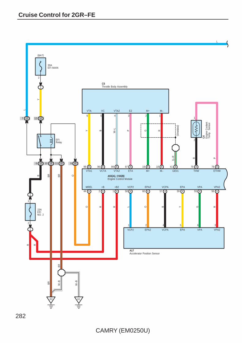
282
CAMRY (EM0250U)
Cruise Control for 2GR–FE
1
79
B
ETHW
B
THW
B
P
78
1
(BAT)
1E
A3
BR
( Shi
elde
d)
5
M+
B
G
M–
B
R
GE01
B
VCTA
411819
C5
B
A17
3
VPA2
6
97
P
B
ETA
99
W–L
B
VTA2
VPA
34 2 1
5
EPA
4
VCPA
2
EPA2
1
VCP2
RGYBOL
VCP2 EPA2 VCPA EPA VPA VPA2
58 60 57 59 55 56 AAAAAA
M–M+E2VTA2VCVTA
98
Y
B
VTA1
B
96
61E
2
1
6 101E
B
2
2
G–R
12
15AEFINO. 2
30AEFI MAIN
1
1
R
1E9
EFIRelay
O
MREL
44 A
O
R
RR
+B2
1 A
+B
2 A
Accelerator Position Sensor
Throttle Body Assembly
Eng
ine
Coo
lant
Tem
p.
Sen
sor
C4
Engine Control ModuleA55(A), C55(B)
YL
1E7
L
1E11
A1
BR
BR
W–B
W–BBR
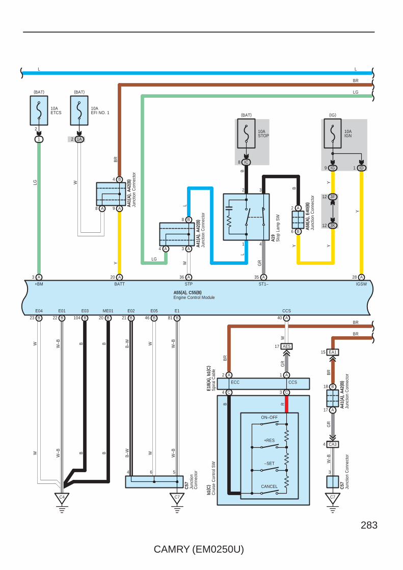
CAMRY (EM0250U)
283
+BM
A
1
LG
(BAT)
3
2
1W
–BB
ID
Y
IGSW
20 46 8121B
ME01
B
E05
B
E1
B W
10AIGN
IG9
ST1–
C7
A
GR
A19
(IG)
2835
B–W
E02
B23 22 104B
E04
B
E01
B
E03
W W–B
C4
10AEFI NO. 1
1A2
(BAT)
W
Y
10AETCS
3F12
3K12
A2
B6
YYY
B
A58(
A), E
40( B
)
6 54
W–BB B WB
–WW W–B
A55(A), C55(B)
Sto
p La
mp
SW
Engine Control Module
Junc
tion
Con
nect
or
Junc
tion
Con
nect
or
C57
10ASTOP
IC8
(BAT)
A3
B8
B
A41(
A), A
42( B
)Ju
nctio
n C
onne
ctor
36
W
A
STP
A20
BATT
A
A4
BR
LL
A8 A9
B4
BR
Junc
tion
Con
nect
orA4
1(A)
, A42
( B)
LG
Cru
ise
Con
trol S
W
3
A
CANCEL
–SET
+RES
ON–OFF
C
A
Spi
ral C
able
Junc
tion
Con
nect
or
4
ECC
C
2
CCS
R
Junc
tion
Con
nect
or1
B
17 AE5C
57A4
1(A)
, A42
( B)
BRW
–BG
R
E18(
A), b
1(C
)b1
( C)
15 EA1
17 A
18 B
4 CA3
3
C7
BR
WG
R
A
CCS
40
BR
BR
LG
1 4
32L
L

284
CAMRY (EM0250U)
Cruise Control for 2GR–FE
TC
A
P
27
SPD
A
V
8
12 AE5
P
A A41
CANL CANH
W B
3H5
3B5
P
Tran
smis
sion
Con
trol S
W
O
5 3C
5 3L
O
7. 5AECU IGNO. 2
B–W
25 B
R
26 B
D
P
L–B
G
G
24 27
L–B
B–W
B
N
B
P
A
S
25A
SFTD
51A
SFTU
16
P
E
10
IG
BR
W–B
YLR
AE5 AE520 AE5
E31
OYLG
(IG)
19 IF1 7
5
2
SFTU SFTD S
3
11
49
4A11
4C12
74D
74C
B1B2
CAN–CAN+
YB
B
W
P
V
LG
BR
L
B
Y
BR
L
Engine Control ModuleA55(A), C55(B)
BR
10 3D
10 3H
11 3A
BR
BR
LG

CAMRY (EM0250U)
285
AE514
A5
A7
V
Junc
tion
Con
nect
or
A41(
A)
JunctionConnector
Par
k/N
eutra
lP
ositi
on S
W
19 CA2
BR
BR
B–W
C572 1
R
O
10 CA2
R
C1(
A)
G
P
B–W
P
L–B
G
G
SPD1
31615
C7
9
BR
E01
8
B–W
E1
(IG)
16 IH
10AGAUGENO. 1
14 EA1
D
R
R
DLNLRLPL
RB
L–B G
SL3–SL3+
L B
P
RW
BR BWBG
SL2–SL2+
BO
SL1+ SL1– SL4+ SL4– SLU+ SLU–CAN+CAN–
67
BY
3P3
3B10
L
BR
LG
V
P
W
BB
W
P
V
LG
BR
L
Y
B
C56Transmission Control ECU
A6
V
V
A1
A7A8A2A3

286
CAMRY (EM0250U)
Cruise Control for 2GR–FE
NTONTBNCONCB
RWBY
HALL SENSORHALL SENSOR
NTONCB
Y
L–BY
YY
B
9 CA2
6 CA24 AE512 3J
12 3F
(IG)
9 IG
10AIGNLBR
9 CA3 11 CA2
W–L
BATT
1
W
+B
18
IG2
13
LG
STP
12
NCO
L GR OW YBRBGR
TPS3 NTBSLT+ SLT– THO1TPS2TPS1SL E2
V
P
W
BB
W
P
V
LG
BR
L
Transmission Control ECUC56

CAMRY (EM0250U)
287
8 C (∗3)(∗2)B8(∗1)A19
C19B29A5
C17B27A6
C7B7A20
C9B9A17
C10B10A3
C6B6A4
C5B5A18
Speed Sensors
LG V P L R L B W
AB
11 (∗1)
A1 A7
26 C35
B4 B10
A2 A8
A25B14C15
A12(∗2)B33(∗3)C23
FL+ FL– FR+ FR– RL+ RL– RR+ RR–
CANH CANL SP1
AE66
BR
W
2 A 1 A 2 B 1 B
W
2 G 1 G
BW
BWBW
B
W
WB
B W
B W
B
W
Junc
tion
Con
nect
orA4
0(A)
, E41
( B)
W B
Junc
tion
Con
nect
orE4
2(A)
, E43
( B) ,
E62(
G)
Ski
d C
ontro
l EC
U w
ith A
ctua
tor
A25(
C) ,
A26(
A), A
60( B
)
Dat
a Li
nkC
onne
ctor
3
E10
∗ 1 : w/ VSC TMC Made∗ 2 : w/ VSC TMMK Made∗ 3 : w/o VSC
V
CANHCANL
TC
14 6
13
P
V
P
14 FE3 13 FE3

288
CAMRY (EM0250U)
Cruise Control for 2GR–FE
7 IF
LG
R
(BAT)
10ADOME
12 A
2 3U
7 3Q
V
12 3Q
1 3D
EA1
SB
GR V
W–B
F1
(IG)
12 IG
7. 5AGAUGENO. 2
(BAT)
10AMPX–B
BIG+ B2
E2
ID13
3L12
3Q1
R
3G2
3Q9
A13 A1 A2
GR
GR V
2
R
A24
3Q5
3D10
A17
B18
CA34
C7
3
GR
W–B
GR
BR
A41(
A), A
42( B
)
C57
ES
IG2
Cru
ise
DRIVE ICMICRO COMPUTER
Power Supply Circuit
W–B
Spe
edom
eter
Junc
tion
Con
nect
or
Junc
tion
Con
nect
or
WB
Com
bina
tion
Met
erF1
( A) ,
F2( B
)
CANLCANH
18 A17 A
IG2
14 B
SI
3P11
3D3
WW
+S
V
B12
IG2
W
W
B
EA115
BR
BR
V11A3
CANI/F

CAMRY (EM0250U)
289
The cruise control system is a constant vehicle speed controller which controls the opening angle of the engine throttle valveby the SW, and allows driving at a constant speed without depressing the accelerator pedal.
Set OperationWhen the ON–OFF SW is turned on, the systems starts preparations for cruise control and turns on the indicator light in thecombination meter.
Set Speed ControlWhen the – SET SW is operated with the ON–OFF SW turned on during driving, the speed is controlled at a constant speed.
Coast ControlWhen the – SET SW is kept turned on during cruise control driving, the engine control module controls the throttle valve todecelerate the vehicle speed.Every time the – SET SW is turned on instantaneously, the vehicle speed is decelerated by approx. 1.6 km/h.
Accel ControlWhen the + RES SW is kept turned on during cruise control driving, the engine control module controls the throttle valve toaccelerate the vehicle speed.Every time the + RES SW is turned on instantaneously, the vehicle speed is accelerated by approx. 1.6 km/h.
Resume ControlIf the vehicle speed is within the low speed limit (Approx. 40 km/h, 25 mph) when canceling the cruise control, operation ofthe + RES SW accelerates the vehicle speed and resumes the level before canceling the cruise control.
Manual Cancel MechanismIf any one of the following signals is input during cruise control driving, the cruise control is canceled.∗ The stop light SW is on∗ The CANCEL SW is turned on∗ The ON–OFF SW is turned off∗ When switching from ON to OFF of ”D” position circuit in neutral start switch.
When the transmission is shifted from ”D” to ”N”.When the transmission is shifted from 5, 4 to 3, 2, 1 in S mode.
Auto Cancel FunctionIf any of the following conditions are detected, the cruise control is canceled:∗ Failure in the stop light SW wiring∗ Abnormality in the vehicle speed signal∗ Malfunction in the electronically controlled throttle parts∗ When the vehicle speed gets slower than the low speed limit.∗ When the vehicle speed falls to 16 km/h less than the set speed.
Overdrive FunctionThe overdrive may be canceled if the vehicle travels on a upward slope during cruise control driving. When the throttleopening information indicates the hill climbing is finished after the overdrive is canceled, the vehicle returns to overdrivemode again as the overdrive return timer is completed.
: Parts Location
Code See Page Code See Page Code See Page
A17 59 A60 B 49 (2GR–FE) E31 56
A19 59 C1 A 50 (2GR–FE) E40 B 57
A25 C 48 (2GR–FE) C4 50 (2GR–FE) E41 B 57
A26 A 48 (2GR–FE) C5 50 (2GR–FE) E42 A 57
A40 A 59 C55 B 51 (2GR–FE) E43 B 57
A41 A 59 C56 51 (2GR–FE) E62 G 57
A42 B 59 C57 51 (2GR–FE) F1 A 58
A55 A 49 (2GR–FE) E10 56 F2 B 58
A58 A 59 E18 A 56 b1 C 59
: Relay Blocks
Code See Page Relay Blocks (Relay Block Location)
1 22 Engine Room R/B (Engine Compartment Left)
System Outline
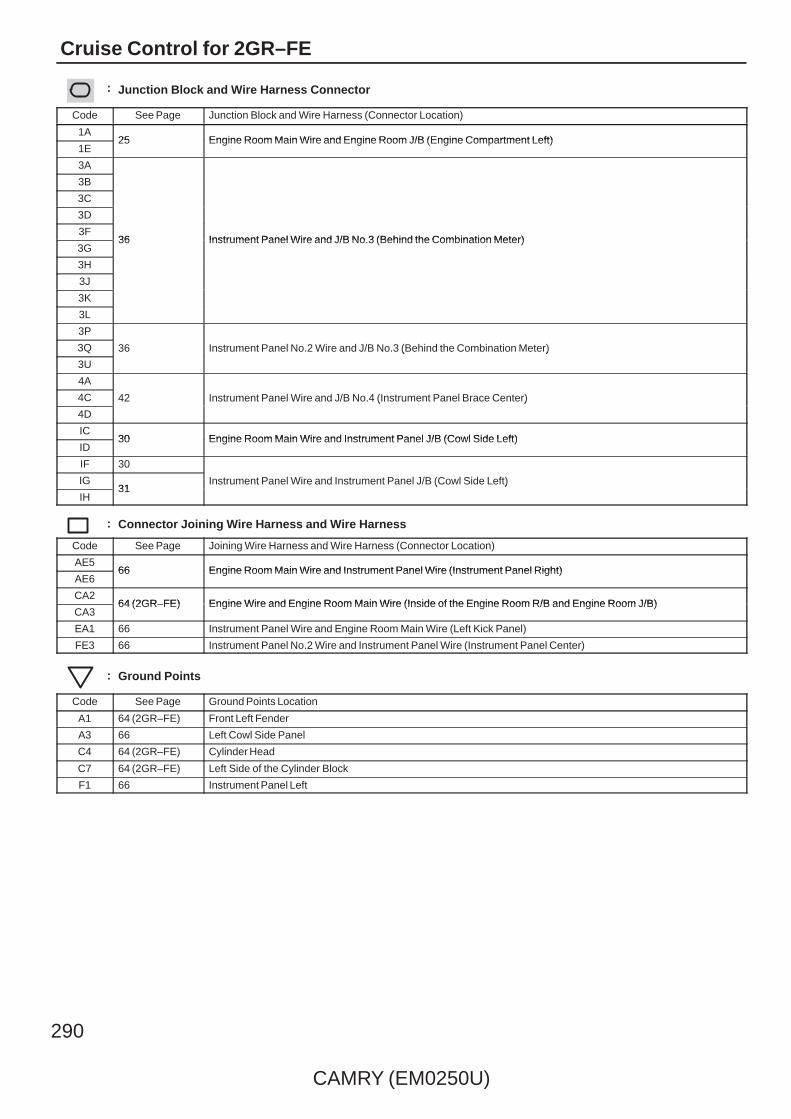
290
CAMRY (EM0250U)
Cruise Control for 2GR–FE
: Junction Block and Wire Harness Connector
Code See Page Junction Block and Wire Harness (Connector Location)
1A25 Engine Room Main Wire and Engine Room J/B (Engine Compartment Left)
1E25 Engine Room Main Wire and Engine Room J/B (Engine Compartment Left)
3A
36 Instrument Panel Wire and J/B No.3 (Behind the Combination Meter)
3B
36 Instrument Panel Wire and J/B No.3 (Behind the Combination Meter)
3C
36 Instrument Panel Wire and J/B No.3 (Behind the Combination Meter)
3D
36 Instrument Panel Wire and J/B No.3 (Behind the Combination Meter)3F
36 Instrument Panel Wire and J/B No.3 (Behind the Combination Meter)3G
36 Instrument Panel Wire and J/B No.3 (Behind the Combination Meter)
3H
3J
3K
3L
3P
36 Instrument Panel No.2 Wire and J/B No.3 (Behind the Combination Meter)3Q 36 Instrument Panel No.2 Wire and J/B No.3 (Behind the Combination Meter)
3U
36 Instrument Panel No.2 Wire and J/B No.3 (Behind the Combination Meter)
4A
42 Instrument Panel Wire and J/B No.4 (Instrument Panel Brace Center)4C 42 Instrument Panel Wire and J/B No.4 (Instrument Panel Brace Center)
4D
42 Instrument Panel Wire and J/B No.4 (Instrument Panel Brace Center)
IC30 Engine Room Main Wire and Instrument Panel J/B (Cowl Side Left)
ID30 Engine Room Main Wire and Instrument Panel J/B (Cowl Side Left)
IF 30
Instrument Panel Wire and Instrument Panel J/B (Cowl Side Left)IG31
Instrument Panel Wire and Instrument Panel J/B (Cowl Side Left)
IH31
Instrument Panel Wire and Instrument Panel J/B (Cowl Side Left)
: Connector Joining Wire Harness and Wire Harness
Code See Page Joining Wire Harness and Wire Harness (Connector Location)
AE566 Engine Room Main Wire and Instrument Panel Wire (Instrument Panel Right)
AE666 Engine Room Main Wire and Instrument Panel Wire (Instrument Panel Right)
CA264 (2GR–FE) Engine Wire and Engine Room Main Wire (Inside of the Engine Room R/B and Engine Room J/B)
CA364 (2GR–FE) Engine Wire and Engine Room Main Wire (Inside of the Engine Room R/B and Engine Room J/B)
EA1 66 Instrument Panel Wire and Engine Room Main Wire (Left Kick Panel)
FE3 66 Instrument Panel No.2 Wire and Instrument Panel Wire (Instrument Panel Center)
: Ground Points
Code See Page Ground Points Location
A1 64 (2GR–FE) Front Left Fender
A3 66 Left Cowl Side Panel
C4 64 (2GR–FE) Cylinder Head
C7 64 (2GR–FE) Left Side of the Cylinder Block
F1 66 Instrument Panel Left

CAMRY (EM0250U)
291
Memo

292
CAMRY (EM0250U)
Cruise Control for 2AZ–FE
EPAVPAVCPAEPA2VPA2VCP2
B
A 57 55A
R GL
EPA2
A
EPA
60
VCP2 VCPA
59
VPA2 VPA
O
56
Y
A58 AA
A17
6 5431 2
3 A
A2 A1
+B2+B
R R
2
+BM
1
LG
(BAT)
20 A
BATT
Y
1
(BAT)
1E
A1
BR
1E
2
1
6 111E
YB
12
30AEFI MAIN
15AEFINO. 2
2
1
R
1
1E9
EFIRelay
O
R
10AEFINO. 1
1A2
(BAT)
44
MREL
A
A8 A9O
W–B
10AETCS
WA41(A)
B16
A18 A16
A9
EOM
A32
EC
A3
A41(
A), A
42( B
)
W–B W
W–B
A24(A), C24(B)
Accelerator Position Sensor
Engine Control Module
JunctionConnector
Junc
tion
Con
nect
or
1E10
A17
B16
A3
Junc
tion
Con
nect
orA4
1(A)
, A42
( B)
BR
W–B
W–B
BR
W–B
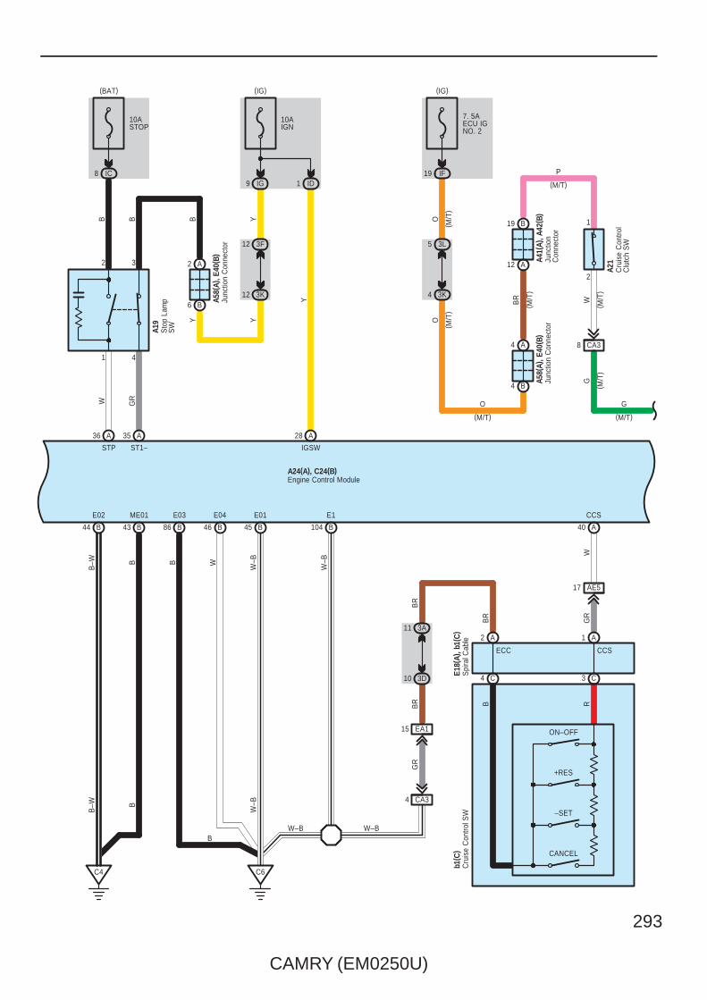
CAMRY (EM0250U)
293
B104
E1
W–B
W–B
E01
45 BB46
E04
WB
ME01
43 BB44
E02
B–W
86
B
B
B
E03
C4 C6
A24(A), C24(B)
W–B
W–B
B–W
Engine Control Module
Junc
tion
Con
nect
or
Sto
p La
mp
SW
A58(
A), E
40( B
)
BY Y
Y
6 B
2 A
12 3K
12 3F
35 28
(IG)
A19
GR
A
ST1–
9 IG
10AIGN
IGSW
A
Y
ID1
A
STP
10ASTOP
IC8
(BAT)W
B
36
B
Cru
ise
Con
trol S
W
3 C4 C
CCS
1 A
ECC
2
–SET
CANCEL
A
B R
15 EA1
W–B
+RES
b1( C
)E1
8(A)
, b1(
C)
Spi
ral C
able
ON–OFF
17 AE5
BR
BR
GR
10 3D
11 3A
BR
WG
R
CCS
40 A
CA34
Junc
tion
Con
nect
orJu
nctio
nC
onne
ctor
Cru
ise
Con
trol
Clu
tch
SW
( M/T
)( M
/T)
( M/T
)
( M/T
)
O
P
WG
BR
O
A58(
A), E
40( B
)A4
1(A)
, A42
( B)
A21
1
2
12 A
19 B
4 B
4 A
7. 5AECU IGNO. 2
(M/T)
IF19(M/T)
(IG)
3L5
3K4
G
(M/T)
O
( M/T
)
1 4
2 3
CA38
B

294
CAMRY (EM0250U)
Cruise Control for 2AZ–FE
Engine Control ModuleA24(A), C24(B)
Electronically Controlled Transmission Solenoid
O Y
B80 B60 B61
SR
11
SL3+ SL3–
V R L
SL3–SL3+SR
49
G
O
E2
ETHO
95 B
BR
7
S4 SLT+ SLT– DSL SL2+ SL2– SL1+ SL1– THO
BW OBR
LGSB
GRGY
THO1SL2–SL2+DSLSLT–SLT+S4
136
L LG
B57 B77
SL1+ SL1–
C25
59 B75 B 72 B58 B79 B76 B78 B
RGBRWLGR Y
3 2 8 10 5 12 1
Park/Neutral Position SW
LL2LDLNLRLPL
74 B
L
LR
G BR
W Y
19 AE6
15 CA2
22 AE6
CA216
GR
O
R
R
R
10 CA2 14 EA1
(IG)
16 IH
10AGAUGENO. 1
VGR
17 CA2
RB
B55A26
3 2
V
OSB
25 A
4
16 AE5
21 AE6
11 CA2
G
B5654 BB53B73
C1(B)
P R N D
SB
PGR
GY
O
L
R
G
(M/T)
( A/T
)
B2
B6 B1 B9 B7 B3 B8
B
B
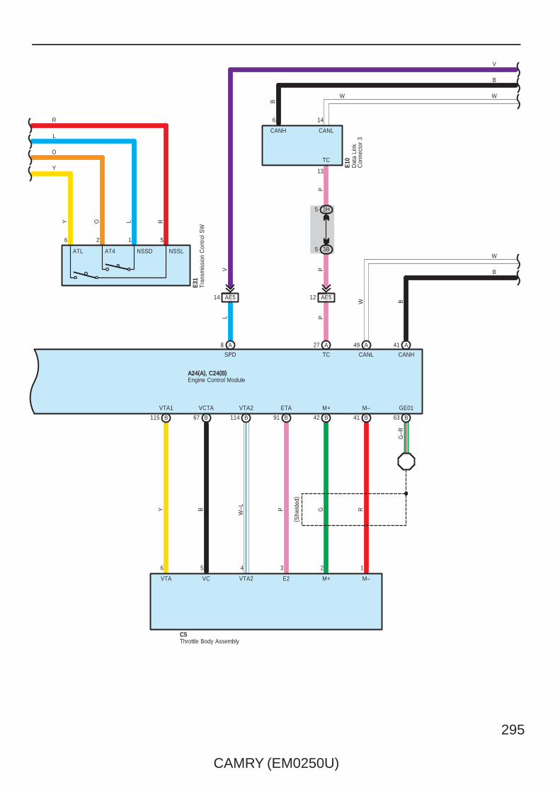
CAMRY (EM0250U)
295
VTA2
G R
67 B B91B115 B114
GE01M–M+VCTA ETAVTA1
Y
( Shi
elde
d)
PB
W–L
63 B41 BB42
G–R
A24(A), C24(B)Engine Control Module
P
AE512
8
L
A
SPD
27
P
A
TC
A49 A41
CANL CANHW B
W
B
3H5
3B5
146
13
Dat
a Li
nkC
onne
ctor
3
E10
P
TC
CANLCANH
B
W
V
W
B
AE514
ATL
Tran
smis
sion
Con
trol S
WE3
1
56
Y RO
NSSDAT4
L
12
NSSL
R
L
O
Y
Throttle Body AssemblyC5
123456
VTA VC VTA2 E2 M+ M–
V

296
CAMRY (EM0250U)
Cruise Control for 2AZ–FE
8 C (∗3)(∗2)B8(∗1)A19
C19B29A5
C17B27A6
C7B7A20
C9B9A17
C10B10A3
C6B6A4
C5B5A18
Speed Sensors
LG V P L R L B W
AB
11 (∗1)
A1 A7
26 C35
B4 B10
A2 A8
A25B14C15
A12(∗2)B33(∗3)C23
FL+ FL– FR+ FR– RL+ RL– RR+ RR–
CANH CANL SP1
AE66
BR
W
2 A 1 A 2 B 1 B
W
2 G 1 G
BW
BWBW
B
W
WB
B W
B W
B
W
Junc
tion
Con
nect
orA4
0(A)
, E41
( B)
W B
Junc
tion
Con
nect
orE4
2(A)
, E43
( B) ,
E62(
G)
Ski
d C
ontro
l EC
U w
ith A
ctua
tor
A25(
C) ,
A26(
A), A
60( B
)
VV
W
B
∗ 2 : w/ VSC TMMK Made∗ 1 : w/ VSC TMC Made
∗ 3 : w/o VSC
14 FE3 13 FE3
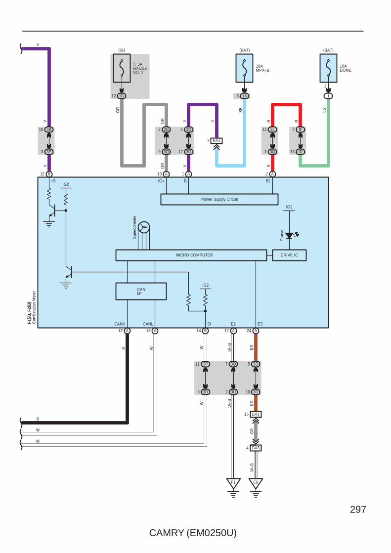
CAMRY (EM0250U)
297
4 CA3
A24
3Q5
3D10
15 EA1
BR
C6
BR
GR
W–B
Spe
edom
eter
W–B
Power Supply Circuit
MICRO COMPUTER
ES
R
2
VGR
GR
2 A1 A13 A
9 3Q
2 3G
R
1 3Q
12 3L
13 ID
E2
B2IG+ B
10AMPX–B
(BAT)
7. 5AGAUGENO. 2
IG12
(IG)
F1
W–B
VGR
SB
EA1
3D1
3Q12
V
3Q7
3U2
A12
10ADOME
1
2
(BAT)
R
LG
IF7
WB
Com
bina
tion
Met
erF1
( A) ,
F2( B
)
CANLCANH
18 A17 A
IG2
14 B
SI
3P11
3D3
WW
V
10 3B
+S
3 3P
V
B12
IG2
W
W
B
V
DRIVE IC
Cru
ise
IG2
1A3
CANI/F
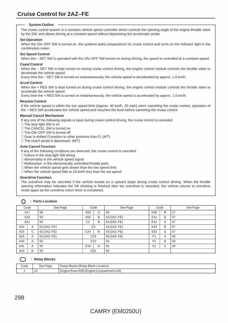
298
CAMRY (EM0250U)
Cruise Control for 2AZ–FE
The cruise control system is a constant vehicle speed controller which controls the opening angle of the engine throttle valveby the SW, and allows driving at a constant speed without depressing the accelerator pedal.
Set OperationWhen the ON–OFF SW is turned on, the systems starts preparations for cruise control and turns on the indicator light in thecombination meter.
Set Speed ControlWhen the – SET SW is operated with the ON–OFF SW turned on during driving, the speed is controlled at a constant speed.
Coast ControlWhen the – SET SW is kept turned on during cruise control driving, the engine control module controls the throttle valve todecelerate the vehicle speed.Every time the – SET SW is turned on instantaneously, the vehicle speed is decelerated by approx. 1.6 km/h.
Accel ControlWhen the + RES SW is kept turned on during cruise control driving, the engine control module controls the throttle valve toaccelerate the vehicle speed.Every time the + RES SW is turned on instantaneously, the vehicle speed is accelerated by approx. 1.6 km/h.
Resume ControlIf the vehicle speed is within the low speed limit (Approx. 40 km/h, 25 mph) when canceling the cruise control, operation ofthe + RES SW accelerates the vehicle speed and resumes the level before canceling the cruise control.
Manual Cancel MechanismIf any one of the following signals is input during cruise control driving, the cruise control is canceled.∗ The stop light SW is on∗ The CANCEL SW is turned on∗ The ON–OFF SW is turned off∗ Gear is shifted D position to other positions than D. (A/T)∗ The clutch pedal is depressed. (M/T)
Auto Cancel FunctionIf any of the following conditions are detected, the cruise control is canceled:∗ Failure in the stop light SW wiring∗ Abnormality in the vehicle speed signal∗ Malfunction in the electronically controlled throttle parts∗ When the vehicle speed gets slower than the low speed limit.∗ When the vehicle speed falls to 16 km/h less than the set speed.
Overdrive FunctionThe overdrive may be canceled if the vehicle travels on a upward slope during cruise control driving. When the throttleopening information indicates the hill climbing is finished after the overdrive is canceled, the vehicle returns to overdrivemode again as the overdrive return timer is completed.
: Parts Location
Code See Page Code See Page Code See Page
A17 59 A58 A 59 E40 B 57
A19 59 A60 B 53 (2AZ–FE) E41 B 57
A21 59 C1 B 54 (2AZ–FE) E42 A 57
A24 A 52 (2AZ–FE) C5 54 (2AZ–FE) E43 B 57
A25 C 52 (2AZ–FE) C24 B 55 (2AZ–FE) E62 G 57
A26 A 52 (2AZ–FE) C25 55 (2AZ–FE) F1 A 58
A40 A 59 E10 56 F2 B 58
A41 A 59 E18 A 56 b1 C 59
A42 B 59 E31 56
: Relay Blocks
Code See Page Relay Blocks (Relay Block Location)
1 22 Engine Room R/B (Engine Compartment Left)
System Outline

CAMRY (EM0250U)
299
: Junction Block and Wire Harness Connector
Code See Page Junction Block and Wire Harness (Connector Location)
1A25 Engine Room Main Wire and Engine Room J/B (Engine Compartment Left)
1E25 Engine Room Main Wire and Engine Room J/B (Engine Compartment Left)
3A
36 Instrument Panel Wire and J/B No.3 (Behind the Combination Meter)
3B
36 Instrument Panel Wire and J/B No.3 (Behind the Combination Meter)
3D
36 Instrument Panel Wire and J/B No.3 (Behind the Combination Meter)3F
36 Instrument Panel Wire and J/B No.3 (Behind the Combination Meter)3G
36 Instrument Panel Wire and J/B No.3 (Behind the Combination Meter)
3H
3K
3L
3P
36 Instrument Panel No.2 Wire and J/B No.3 (Behind the Combination Meter)3Q 36 Instrument Panel No.2 Wire and J/B No.3 (Behind the Combination Meter)
3U
36 Instrument Panel No.2 Wire and J/B No.3 (Behind the Combination Meter)
IC30 Engine Room Main Wire and Instrument Panel J/B (Cowl Side Left)
ID30 Engine Room Main Wire and Instrument Panel J/B (Cowl Side Left)
IF 30
Instrument Panel Wire and Instrument Panel J/B (Cowl Side Left)IG31
Instrument Panel Wire and Instrument Panel J/B (Cowl Side Left)
IH31
Instrument Panel Wire and Instrument Panel J/B (Cowl Side Left)
: Connector Joining Wire Harness and Wire Harness
Code See Page Joining Wire Harness and Wire Harness (Connector Location)
AE566 Engine Room Main Wire and Instrument Panel Wire (Instrument Panel Right)
AE666 Engine Room Main Wire and Instrument Panel Wire (Instrument Panel Right)
CA265 (2AZ–FE) Engine Wire and Engine Room Main Wire (Inside of the Engine Room R/B and Engine Room J/B)
CA365 (2AZ–FE) Engine Wire and Engine Room Main Wire (Inside of the Engine Room R/B and Engine Room J/B)
EA1 66 Instrument Panel Wire and Engine Room Main Wire (Left Kick Panel)
FE3 66 Instrument Panel No.2 Wire and Instrument Panel Wire (Instrument Panel Center)
: Ground Points
Code See Page Ground Points Location
A1 65 (2AZ–FE) Front Left Fender
A3 66 Left Cowl Side Panel
C465 (2AZ–FE) Cylinder Block
C665 (2AZ–FE) Cylinder Block
F1 66 Instrument Panel Left

300
CAMRY (EM0250U)
ECT and A/T Indicator for 2GR–FE
1
(BAT)
1E
A3
BR
1E
2
1
6 101E
B
2
12
10AEFINO. 3
30AEFI MAIN
15AEFINO. 2
2
1
1
1
R
1
1E9
EFIRelay
O
R
GR
GR
R
R
O
ST2
IG2AM2
E23Ignition SW
GR
CA2
P
N
BL
4
3
AM1
ACC
IG1
ST1
8
C1(
A)
W
9 A
4 A
53E
53F
EA16
YP
W
Y
Par
k/N
eutra
lP
ositi
on S
W
GR
II4
O
LG
L
ST Relay
7 EA1
2
7. 5AAM2
Y
(BAT)
1
G
L
Y
(BAT)
(∗2)
(∗2) (∗2)
( ∗2)
( ∗1)
(∗1)
∗ 1 : w/ Smart Key System∗ 2 : w/o Smart Key System
(∗1)
1E7
L–B
Y
L
W–B
BR
1E11
BR
A1
W–B
W–B
W–BBR
7. 5AAM1
L

CAMRY (EM0250U)
301
7CA2
VLG
L
JunctionConnector
G
13 AE6
A2
A435
V
13 EA1
9 4E
8 4K
G
9 4F
9 4G
B8D6
GV
STR2
R
R
L
ST
CU
TR
elay
1 1
1 1
25
13
Y
STR
L
CA218
AM2LL
AM1
4G12 4M12
4E12
1B6 A
R(∗1)
L–B
V
GR
R
R
OO
R
R
GR
G
L
Main Body ECUE6(A), E7(B), E9(D)
(∗1)
(∗1)
( ∗1)
( ∗1)
( ∗1)
( ∗1)
( ∗1)
( ∗1)
( ∗1)
( ∗1)
(∗1)
( ∗1)
( ∗1)
R(∗1)
Y
9 IG
3J12
3F12
AE54
L
Y
L
L–B
Y
L
10AIGN
(IG)
Y

302
CAMRY (EM0250U)
ECT and A/T Indicator for 2GR–FE
( Shi
elde
d)
E2G
B
4
LG
VG
B
5
L–B
THA
B
1
P
3
+B
E2G VG THA
5
M+
B
G
M–
B
R
GE01
B
R
VCTA
717273 411819
C5
B 97P
B
ETA
99
W–L
B
VTA2
34 2 1
M–M+E2VTA2VCVTA
98
Y
B
VTA1
B
96
6
ETHA
B
2
G–R
E2
74
C2
G–R
CA23
MREL
44 A
O
GR
RR
+B2
1 A
+B
2 A
GR
R
R
O
W–L
Mass Air FlowMeter
Throttle Body Assembly
L–B
62
NSW
B 48
V
STA
A63
R
STAR
B
L–B
R(∗1)
R
Engine Control ModuleA55(A), C55(B)
( ∗1)
L
Y
L
L
Y
L
V
∗ 1 : w/ Smart Key System

CAMRY (EM0250U)
303
1
79
B
ETHW
B
THW
B
P
78
+BM
A
1
LG
(BAT)
3
2
W–BB
20 46 8121B
ME01
B
E05
B
E1
B W
C7
A17
3
VPA2
6
VPA
5
EPA
4
VCPA
2
EPA2
1
VCP2
RGYBOL
VCP2 EPA2 VCPA EPA VPA VPA2
58 60 57 59 55 56 AAAAAA
B–W
E02
B23 22 104B
E04
B
E01
B
E03
W W–B
C4
2
10AEFI NO. 1
1A2
(BAT)
W
Y
10AETCS
6 54
W–BB B WB
–WW W–B
A55(A), C55(B)
Accelerator Position Sensor
Engine Control Module
Eng
ine
Coo
lant
Tem
p.
Sen
sor
C4
Junc
tion
Con
nect
or
C57
A20
BATT
BR
L
Y
L
L
Y
L
A8 A9
B4
BR
Junc
tion
Con
nect
orA4
1(A)
, A42
( B)

304
CAMRY (EM0250U)
ECT and A/T Indicator for 2GR–FE
1 ID
Y
IGSW
10AIGN
IG9
ST1–
A
GR
A19
(IG)
2835
3F12
3K12
A2
B6
YY
YB
A58(
A), E
40( B
)
Sto
p La
mp
SW
Junc
tion
Con
nect
or
10ASTOP
IC8
(BAT)
A3
B8
B
A41(
A), A
42( B
)Ju
nctio
n C
onne
ctor
36
W
A
STP
Tran
smis
sion
Con
trol S
W
Junc
tion
Con
nect
orJu
nctio
n C
onne
ctor
C57
A41(
A), A
42( B
)
BR
W–B
GR
10 3H
10 3D
15 EA1
17 A
18 B
4 CA3
3
C7
O
5 3C
5 3L
O
7. 5AECU IGNO. 2
A
S
25A
SFTD
51A
SFTU
16
E
10
IG
BR
BR
W–B
YLR
AE5 AE520 AE5
E31
O
O
YLG
(IG)
19 IF1 7
5
2
SFTU SFTD S
3
11
A
4A11
4C12
74D
74C
A4
L
Y
L
BR
LG
BR
L
Y
L
Engine Control ModuleA55(A), C55(B)
LG
1 4
2 3
L
L

CAMRY (EM0250U)
305
TC
A
P
A55(A), C55(B)
27
SPD
A
V
8
12 AE5
P
Engine Control Module
A A41
CANL CANH
W B
3H5
3B5
P
B–W
25 B
R
26 B
D
P
L–B
GG
24 27
L–B
B–W
B
N
B
P
P
49
B1B2
CAN–CAN+
YB
B
W
P
V
LG
BR
L
Y
L
B
Y
LG
BR
L
Y
L
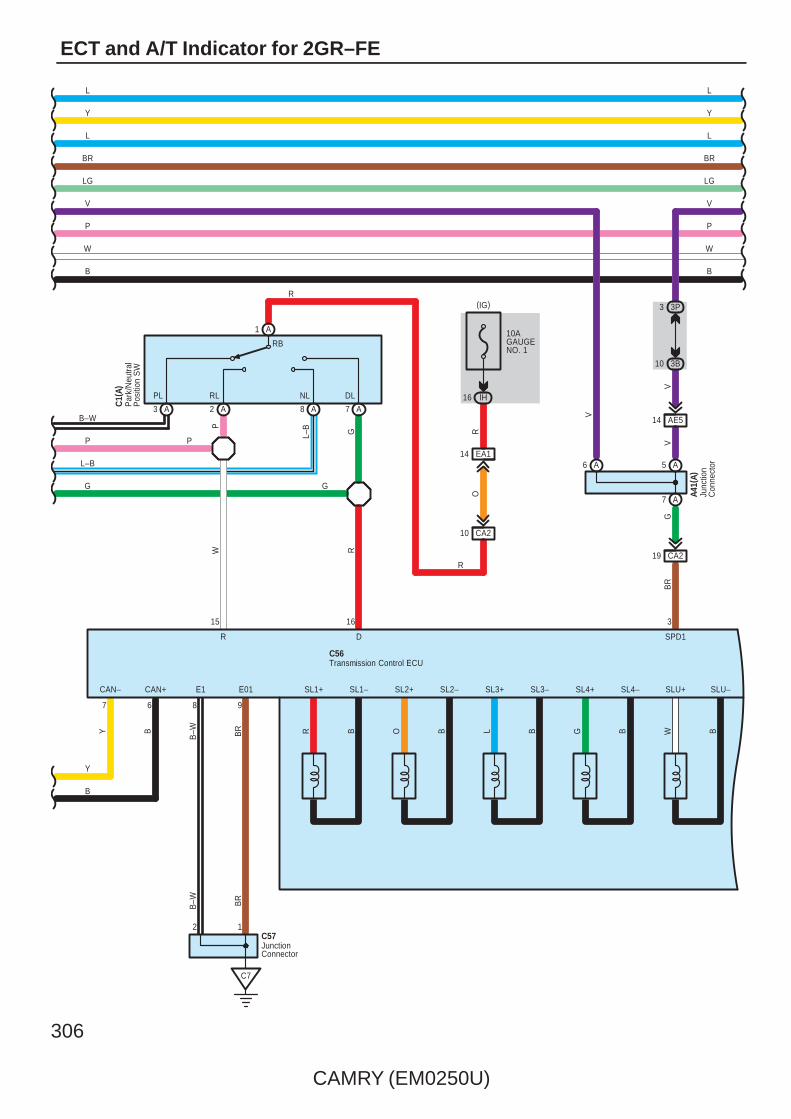
306
CAMRY (EM0250U)
ECT and A/T Indicator for 2GR–FE
AE514
A5
A7
V
Junc
tion
Con
nect
or
A41(
A)
JunctionConnector
Par
k/N
eutra
lP
ositi
on S
W
19 CA2
BR
BR
B–W
C572 1
R
O
10 CA2
R
C1(
A)
G
P
B–W
P
L–B
G
G
SPD1
31615
C7
9
BR
E01
8
B–W
E1
(IG)
16 IH
10AGAUGENO. 1
14 EA1
D
R
R
DLNLRLPL
RB
L–B G
SL3–SL3+
L B
P
RW
BR BWBG
SL2–SL2+
BO
SL1+ SL1– SL4+ SL4– SLU+ SLU–CAN+CAN–
67
BY
3P3
3B10
L
Y
L
BR
LG
V
P
W
BB
W
P
V
LG
BR
L
Y
L
Y
B
C56Transmission Control ECU
A6
V
V
A1
A3 A2 A8 A7
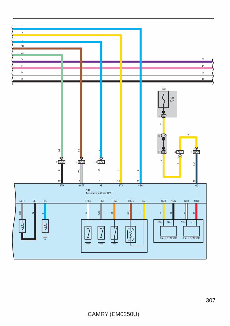
CAMRY (EM0250U)
307
NTONTBNCONCB
RWBY
HALL SENSORHALL SENSOR
NTONCB
Y
L–BY
YY
B
9 CA2
6 CA24 AE512 3J
12 3F
(IG)
9 IG
10AIGN
LBR
9 CA3 11 CA2
W–L
BATT
1
W
+B
18
IG2
13
LG
STP
12
L
NSW
11
Y
STA
10
NCO
L GR OW YBRBGR
TPS3 NTBSLT+ SLT– THO1TPS2TPS1SL E2
V
P
W
BB
W
P
V
LG
BR
L
Y
L
Transmission Control ECUC56

308
CAMRY (EM0250U)
ECT and A/T Indicator for 2GR–FE
8 C (∗5)(∗4)B8(∗3)A19
C19B29A5
C17B27A6
C7B7A20
C9B9A17
C10B10A3
C6B6A4
C5B5A18
Speed Sensors
LG V P L R L B W
AB
11 (∗3)
A1 A7
26 C35
B4 B10
A2 A8
A25B14C15
A12(∗4)B33(∗5)C23
FL+ FL– FR+ FR– RL+ RL– RR+ RR–
CANH CANL SP1
AE66
BR
W
2 A 1 A 2 B 1 B
W
2 G 1 G
BW
BWBW
B
W
WB
B W
B WB
W
Junc
tion
Con
nect
orA4
0(A)
, E41
( B)
W B
Junc
tion
Con
nect
orE4
2(A)
, E43
( B) ,
E62(
G)
Ski
d C
ontro
l EC
U w
ith A
ctua
tor
A25(
C) ,
A26(
A), A
60( B
)
Dat
a Li
nkC
onne
ctor
3
E10
∗ 3 : w/ VSC TMC Made∗ 4 : w/ VSC TMMK Made∗ 5 : w/o VSC
V
CANHCANL
TC
14 6
13
P
V
P
FE314 FE313

CAMRY (EM0250U)
309
7 IF
LG
R
(BAT)
2
1
10ADOME
12 A
2 3U
7 3Q
V
12 3Q
1 3D
EA1
SB
GR V
W–B
F1
(IG)
12 IG
7. 5AGAUGENO. 2
(BAT)
10AMPX–B
BIG+ B2
E2
ID13
3L12
3Q1
R
3G2
3Q9
A13 A1 A2
GR
GR V
2
R
A24
3Q5
3D10
A17
B18
CA34
C7
3
GR
W–B
GR
BR
A41(
A), A
42( B
)
C57
ES
MICRO COMPUTER
Power Supply Circuit
LCDA/T Range
W–B
Spe
edom
eter
Junc
tion
Con
nect
or
Junc
tion
Con
nect
or
WB
Com
bina
tion
Met
erF1
( A) ,
F2( B
)
CANLCANH
18 A17 A 14 B
SI
3P11
3D3
WW
+S
V
B12
W
W
B
EA115
BR
BR
SDNRP
DRIVE IC
IG2
V1A3
CANI/F
IG2
IG2

310
CAMRY (EM0250U)
ECT and A/T Indicator for 2GR–FE
1. Line Pressure Optimal ControlThrough the use of the solenoid valve SLT, the line pressure is optimally controlled in accordance with the engine torqueinformation, as well as with the internal operating conditions of the torque converter and the transaxle. Accordingly, the linepressure can be controlled minutely in accordance with the engine output, traveling condition, and the ATF temperature, thusrealizing smooth shift characteristics and optimizing the workload in the oil pump.
2. Clutch Pressure Optimal ControlThe engine control module monitors the signals from various types of sensor such as the input turbine speed sensor,allowing shift solenoid valves SL1, SL2 and SL3 to minutely control the clutch pressure in accordance with engine outputand driving conditions. As a result, smooth shift characteristics have been realized.
3. Shifting Control in Uphill/Downhill TravelingThis control minimizes the shifting of gears when the driver operates the accelerator pedal while driving on a winding roadwith ups and downs, in order to ensure a smooth drive.
4. Flex Lock–Up Clutch ControlThe flex lock–up clutch control operates during acceleration, in the 4th and 5th gear in the D range, and during deceleration,in the 4th and 5th gear in the D range and in the 4th gear in the 4 range.
5. Multi Mode Automatic TransmissionMulti mode automatic transmission have [S]–position is beside of [D]–position. If moving the selector lever ”S” side, you canselect shift range just link manual shifting.
: Parts Location
Code See Page Code See Page Code See Page
A17 59 C1 A 50 (2GR–FE) E23 56
A19 59 C2 50 (2GR–FE) E31 56
A25 C 48 (2GR–FE) C4 50 (2GR–FE) E40 B 57
A26 A 48 (2GR–FE) C5 50 (2GR–FE) E41 B 57
A40 A 59 C55 B 51 (2GR–FE) E42 A 57
A41 A 59 C56 51 (2GR–FE) E43 B 57
A42 B 59 C57 51 (2GR–FE) E62 G 57
A43 49 (2GR–FE) E6 A 56 F1 A 58
A55 A 49 (2GR–FE) E7 B 56 F2 B 58
A58 A 59 E9 D 56
A60 B 49 (2GR–FE) E10 56
: Relay Blocks
Code See Page Relay Blocks (Relay Block Location)
1 22 Engine Room R/B (Engine Compartment Left)
System Outline
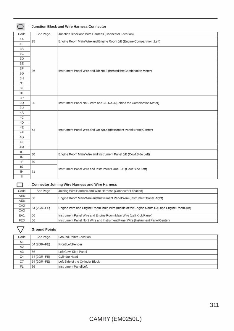
CAMRY (EM0250U)
311
: Junction Block and Wire Harness Connector
Code See Page Junction Block and Wire Harness (Connector Location)
1A25 Engine Room Main Wire and Engine Room J/B (Engine Compartment Left)
1E25 Engine Room Main Wire and Engine Room J/B (Engine Compartment Left)
3B
36 Instrument Panel Wire and J/B No.3 (Behind the Combination Meter)
3C
36 Instrument Panel Wire and J/B No.3 (Behind the Combination Meter)
3D
36 Instrument Panel Wire and J/B No.3 (Behind the Combination Meter)
3E
36 Instrument Panel Wire and J/B No.3 (Behind the Combination Meter)3F
36 Instrument Panel Wire and J/B No.3 (Behind the Combination Meter)3G
36 Instrument Panel Wire and J/B No.3 (Behind the Combination Meter)
3H
3J
3K
3L
3P
36 Instrument Panel No.2 Wire and J/B No.3 (Behind the Combination Meter)3Q 36 Instrument Panel No.2 Wire and J/B No.3 (Behind the Combination Meter)
3U
36 Instrument Panel No.2 Wire and J/B No.3 (Behind the Combination Meter)
4A
42 Instrument Panel Wire and J/B No.4 (Instrument Panel Brace Center)
4C
42 Instrument Panel Wire and J/B No.4 (Instrument Panel Brace Center)
4D
42 Instrument Panel Wire and J/B No.4 (Instrument Panel Brace Center)4E
42 Instrument Panel Wire and J/B No.4 (Instrument Panel Brace Center)4F
42 Instrument Panel Wire and J/B No.4 (Instrument Panel Brace Center)
4G
4K
4M
IC30 Engine Room Main Wire and Instrument Panel J/B (Cowl Side Left)
ID30 Engine Room Main Wire and Instrument Panel J/B (Cowl Side Left)
IF 30
Instrument Panel Wire and Instrument Panel J/B (Cowl Side Left)IG
31Instrument Panel Wire and Instrument Panel J/B (Cowl Side Left)
IH 31Instrument Panel Wire and Instrument Panel J/B (Cowl Side Left)
II
31
: Connector Joining Wire Harness and Wire Harness
Code See Page Joining Wire Harness and Wire Harness (Connector Location)
AE566 Engine Room Main Wire and Instrument Panel Wire (Instrument Panel Right)
AE666 Engine Room Main Wire and Instrument Panel Wire (Instrument Panel Right)
CA264 (2GR–FE) Engine Wire and Engine Room Main Wire (Inside of the Engine Room R/B and Engine Room J/B)
CA364 (2GR–FE) Engine Wire and Engine Room Main Wire (Inside of the Engine Room R/B and Engine Room J/B)
EA1 66 Instrument Panel Wire and Engine Room Main Wire (Left Kick Panel)
FE3 66 Instrument Panel No.2 Wire and Instrument Panel Wire (Instrument Panel Center)
: Ground Points
Code See Page Ground Points Location
A164 (2GR–FE) Front Left Fender
A264 (2GR–FE) Front Left Fender
A3 66 Left Cowl Side Panel
C4 64 (2GR–FE) Cylinder Head
C7 64 (2GR–FE) Left Side of the Cylinder Block
F1 66 Instrument Panel Left

312
CAMRY (EM0250U)
ECT and A/T Indicator for 2AZ–FE
3 A
V
A2 A1
+B2+B
R R
2
+BM
1
LG
(BAT)
P
97 B B96
THW ETHW
B
2
1
20 A
BATT
Y
1
(BAT)
1E
A1
BR
1E
2
1
6 111E
YB
2
12
10AEFINO. 3
30AEFI MAIN
15AEFINO. 2
2
1
1
1
R
1
1E9
EFIRelay
O
R
GR
10AEFINO. 1
1A2
(BAT)
44
MREL
A
A8 A9
O
10AETCS
W
A41(A)
A24(A), C24(B)Engine Control Module
JunctionConnector E
ngin
e C
oola
ntTe
mp.
S
enso
r
C4
1E10
A17
B16
A3
Junc
tion
Con
nect
orA4
1(A)
, A42
( B)
BR
W–B
W–B
W–B
W–B
CA23GR
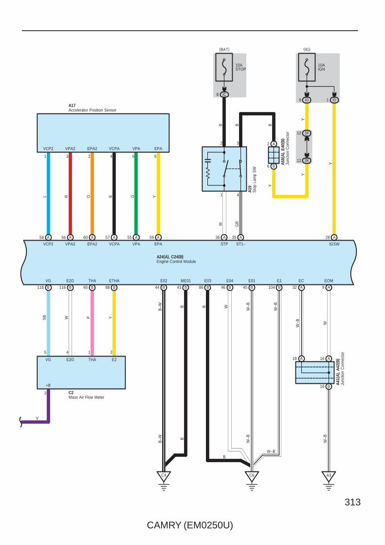
CAMRY (EM0250U)
313
B104
E1W
–B
W–B
E01
45 BB46
E04
WB
ME01
43 BB44
E02
B–W
EPAVPAVCPAEPA2VPA2VCP2
B
A 57 55A
R GL
EPA2
A
EPA
60
VCP2 VCPA
59
VPA2 VPA
O
56
Y
A58 AA
A17
6 5431 2
86
B
B
B118 B116 B65 B88
SB W P Y
B
V
C2
VG E2G THA E2
+B
E03
3
5 4 1 2
VG E2G THA ETHA
C4 C6
A24(A), C24(B)
W–B
W–B
B–W
B16
A18 A16
A9
EOM
A32
EC
A3
A41(
A), A
42( B
)
W–B W
W–B
Accelerator Position Sensor
Engine Control Module
Junc
tion
Con
nect
or
Mass Air Flow Meter
Junc
tion
Con
nect
or
Sto
p La
mp
SW
A58(
A), E
40( B
)
BY
YY
6 B
2 A
12 3K
12 3F
35 28
(IG)
A19
GR
A
ST1–
9 IG
10AIGN
IGSW
A
Y
ID1
A
STP
10ASTOP
IC8
(BAT)
WB
36B
1 4
2 3
B

314
CAMRY (EM0250U)
ECT and A/T Indicator for 2AZ–FE
Engine Control ModuleA24(A), C24(B)
Electronically Controlled Transmission Solenoid
O Y
B80 B60 B61
SR
11
SL3+ SL3–
V R L
SL3–SL3+SR
49
G
O
E2
ETHO
95 B
BR
7
S4 SLT+ SLT– DSL SL2+ SL2– SL1+ SL1– THO
BW OBR
LGSB
GRGY
THO1SL2–SL2+DSLSLT–SLT+S4
136
L LG
B57 B77
SL1+ SL1–
C25
59 B75 B 72 B58 B79 B76 B78 B
RGBRWLGR Y
3 2 8 10 5 12 1
Park/Neutral Position SW
LL2LDLNLRLPL
74 B
L
LR
G BR
W Y
19 AE6
15 CA2
22 AE6
CA216
GR
O
R
R
R
10 CA2 14 EA1
(IG)
16 IH
10AGAUGENO. 1
VGR
17 CA2
RB
B55A26
3 2
V
OSB
25 A
4
16 AE5
21 AE6
11 CA2
G
B5654 BB53B73
C1(B)
P R N D
SB
PGR
GY
O
L
R
B2
B8B3B7B9B1B6
B
B
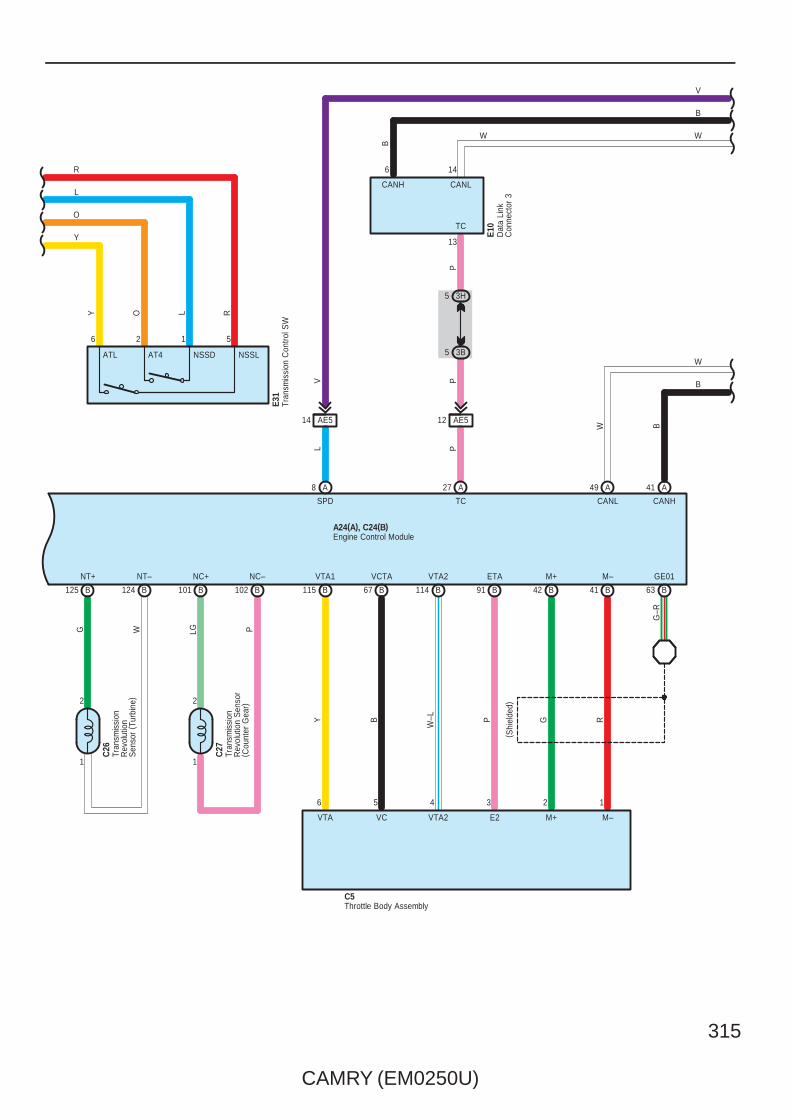
CAMRY (EM0250U)
315
VTA2
G R67 B B91B115 B114
GE01M–M+VCTA ETAVTA1
Y
( Shi
elde
d)
PB
W–L
63 B41 BB42
G–R
A24(A), C24(B)Engine Control Module
P
AE512
8
L
A
SPD
27
P
A
TC
A49 A41
CANL CANH
W B
W
B
3H5
3B5
146
13
Dat
a Li
nkC
onne
ctor
3
E10
P
TC
CANLCANH
B
W
V
W
B
AE514
NC–NC+NT–NT+
PLGWG
B101 B102124 B125 B
ATL
Tran
smis
sion
Con
trol S
WE3
1
56
Y RO
NSSDAT4
L
12
NSSL
R
L
O
Y
Tran
smis
sion
Rev
olut
ion
Sen
sor
( Tur
bine
)
C26
Tran
smis
sion
Rev
olut
ion
Sen
sor
( Cou
nter
Gea
r)
C27
Throttle Body AssemblyC5
1 1
123456
22
VTA VC VTA2 E2 M+ M–
V
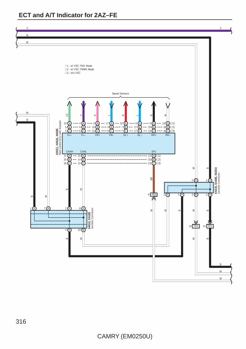
316
CAMRY (EM0250U)
ECT and A/T Indicator for 2AZ–FE
8 C (∗3)(∗2)B8(∗1)A19
C19B29A5
C17B27A6
C7B7A20
C9B9A17
C10B10A3
C6B6A4
C5B5A18
Speed Sensors
LG V P L R L B W
AB
11 (∗1)
A1 A7
26 C35
B4 B10
A2 A8
A25B14C15
A12(∗2)B33(∗3)C23
FL+ FL– FR+ FR– RL+ RL– RR+ RR–
CANH CANL SP1
AE66
BR
W
2 A 1 A 2 B 1 B
W
2 G 1 G
BW
BWBW
B
W
WB
B W
B W
B
W
Junc
tion
Con
nect
orA4
0(A)
, E41
( B)
W B
Junc
tion
Con
nect
orE4
2(A)
, E43
( B) ,
E62(
G)
Ski
d C
ontro
l EC
U w
ith A
ctua
tor
A25(
C) ,
A26(
A), A
60( B
)
VV
W
B
∗ 2 : w/ VSC TMMK Made∗ 1 : w/ VSC TMC Made
∗ 3 : w/o VSC
14 FE3 13 FE3

CAMRY (EM0250U)
317
4 CA3
A24
3Q5
3D10
15 EA1
BR
C6
BR
GR
W–B
Spe
edom
eter
W–B
Power Supply Circuit
MICRO COMPUTER
ES
R
2
VGR
GR
2 A1 A13 A
9 3Q
2 3G
R
1 3Q
12 3L
13 ID
E2
B2IG+ B
10AMPX–B
(BAT)
7. 5AGAUGENO. 2
IG12
(IG)
F1
W–B
VGR
SB
EA1
3D1
3Q12
V
3Q7
3U2
A12
10ADOME
1
2
(BAT)
R
LG
IF7WB
Com
bina
tion
Met
erF1
( A) ,
F2( B
)
CANLCANH
18 A17 A 14 B
SI
3P11
3D3
WW
V
10 3B
+S
3 3P
V
B12
W
W
B
V
4, 3
, 2, L
DNRP
DRIVE IC
IG2
1A3
CANI/F
IG2
IG2

318
CAMRY (EM0250U)
ECT and A/T Indicator for 2AZ–FE
1. Line Pressure Optimal ControlThrough the use of the solenoid valve SLT, the line pressure is optimally controlled in accordance with the engine torqueinformation, as well as with the internal operating conditions of the torque converter and the transaxle. Accordingly, the linepressure can be controlled minutely in accordance with the engine output, traveling condition, and the ATF temperature, thusrealizing smooth shift characteristics and optimizing the workload in the oil pump.
2. Clutch Pressure Optimal ControlThe engine control module monitors the signals from various types of sensor such as the input turbine speed sensor,allowing shift solenoid valves SL1, SL2 and SL3 to minutely control the clutch pressure in accordance with engine outputand driving conditions. As a result, smooth shift characteristics have been realized.
3. Shifting Control in Uphill/Downhill TravelingThis control minimizes the shifting of gears when the driver operates the accelerator pedal while driving on a winding roadwith ups and downs, in order to ensure a smooth drive.
4. Flex Lock–Up Clutch ControlThe flex lock–up clutch control operates during acceleration, in the 4th and 5th gear in the D range, and during deceleration,in the 4th and 5th gear in the D range and in the 4th gear in the 4 range.
: Parts Location
Code See Page Code See Page Code See Page
A17 59 A60 B 53 (2AZ–FE) E10 56
A19 59 C1 B 54 (2AZ–FE) E31 56
A24 A 52 (2AZ–FE) C2 54 (2AZ–FE) E40 B 57
A25 C 52 (2AZ–FE) C4 54 (2AZ–FE) E41 B 57
A26 A 52 (2AZ–FE) C5 54 (2AZ–FE) E42 A 57
A40 A 59 C24 B 55 (2AZ–FE) E43 B 57
A41 A 59 C25 55 (2AZ–FE) E62 G 57
A42 B 59 C26 55 (2AZ–FE) F1 A 58
A58 A 59 C27 55 (2AZ–FE) F2 B 58
: Relay Blocks
Code See Page Relay Blocks (Relay Block Location)
1 22 Engine Room R/B (Engine Compartment Left)
: Junction Block and Wire Harness Connector
Code See Page Junction Block and Wire Harness (Connector Location)
1A25 Engine Room Main Wire and Engine Room J/B (Engine Compartment Left)
1E25 Engine Room Main Wire and Engine Room J/B (Engine Compartment Left)
3B
36 Instrument Panel Wire and J/B No.3 (Behind the Combination Meter)
3D
36 Instrument Panel Wire and J/B No.3 (Behind the Combination Meter)
3F
36 Instrument Panel Wire and J/B No.3 (Behind the Combination Meter)3G 36 Instrument Panel Wire and J/B No.3 (Behind the Combination Meter)
3H
36 Instrument Panel Wire and J/B No.3 (Behind the Combination Meter)
3K
3L
3P
36 Instrument Panel No.2 Wire and J/B No.3 (Behind the Combination Meter)3Q 36 Instrument Panel No.2 Wire and J/B No.3 (Behind the Combination Meter)
3U
36 Instrument Panel No.2 Wire and J/B No.3 (Behind the Combination Meter)
IC30 Engine Room Main Wire and Instrument Panel J/B (Cowl Side Left)
ID30 Engine Room Main Wire and Instrument Panel J/B (Cowl Side Left)
IF 30
Instrument Panel Wire and Instrument Panel J/B (Cowl Side Left)IG31
Instrument Panel Wire and Instrument Panel J/B (Cowl Side Left)
IH31
Instrument Panel Wire and Instrument Panel J/B (Cowl Side Left)
System Outline

CAMRY (EM0250U)
319
: Connector Joining Wire Harness and Wire Harness
Code See Page Joining Wire Harness and Wire Harness (Connector Location)
AE566 Engine Room Main Wire and Instrument Panel Wire (Instrument Panel Right)
AE666 Engine Room Main Wire and Instrument Panel Wire (Instrument Panel Right)
CA265 (2AZ–FE) Engine Wire and Engine Room Main Wire (Inside of the Engine Room R/B and Engine Room J/B)
CA365 (2AZ–FE) Engine Wire and Engine Room Main Wire (Inside of the Engine Room R/B and Engine Room J/B)
EA1 66 Instrument Panel Wire and Engine Room Main Wire (Left Kick Panel)
FE3 66 Instrument Panel No.2 Wire and Instrument Panel Wire (Instrument Panel Center)
: Ground Points
Code See Page Ground Points Location
A1 65 (2AZ–FE) Front Left Fender
A3 66 Left Cowl Side Panel
C465 (2AZ–FE) Cylinder Block
C665 (2AZ–FE) Cylinder Block
F1 66 Instrument Panel Left
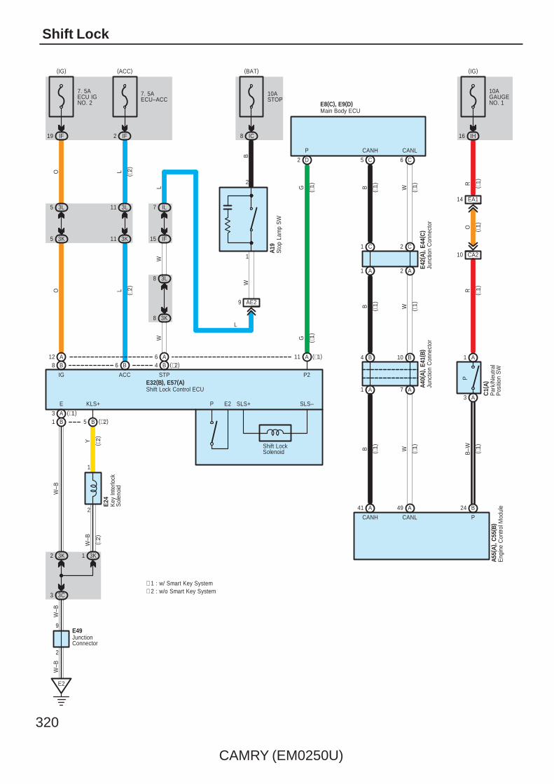
320
CAMRY (EM0250U)
Shift Lock
2
E24
Key
Inte
rlock
Sol
enoi
d
JunctionConnector
Shift Lock Control ECU
6 A4 B (∗2)
11
E2
A6 B
P
12 A8 B
(∗1)
7. 5AECU–ACC
7. 5AECU IGNO. 2
STP
W ( ∗1)
( ∗2)L
IF2
(ACC)
ACC
L
3L11
3K
1
11
2 3K 1 3K
E
W–B
( ∗2)Y
E32(B), E57(A)
( ∗2)
W–B
KLS+
( ∗2)
P2
Shift LockSolenoid
IG
O
SLS+ SLS–
3L5
3K5
O
IF19
G
(IG)
3C3
W–B
E2
A3B1 (∗2)B5
9
2
E49
W–B
∗ 1 : w/ Smart Key System∗ 2 : w/o Smart Key System
A40(
A), E
41( B
)
7 A1 A
4 B 10 B
Junc
tion
Con
nect
or
( ∗1)R
B–W ( ∗1)
CANH CANL
W
49 A
B
41 A
( ∗1)
( ∗1)
R
EA114
10AGAUGENO. 1
IH16
(IG)
P
B24
CA210
O
( ∗1)
( ∗1)
A1
A3
10ASTOP
IC8
(BAT)
B
AE29
W
Sto
p La
mp
SW
A19
3L8
3K8
IL7
IF15
W
(∗1)
D2
( ∗1)G
P
Eng
ine
Con
trol M
odul
eA5
5(A)
, C55
( B)
P
Par
k/N
eutra
lP
ositi
on S
W
C1(
A)
E42(
A), E
44( C
)
2 A1 A
1 C 2 C
Junc
tion
Con
nect
or
( ∗1)
5 C
B
CANH
( ∗1)
6 C
W
CANL
( ∗1)B ( ∗1)W
Main Body ECUE8(C), E9(D)
1
2
L
L

CAMRY (EM0250U)
321
Shift Lock MechanismIf the brake pedal is depressed with the power SW is pushed to IG ON position (Power SW type), or the ignition SW is turnedto ON (Ignition SW type), the shift lock control ECU is activated, allowing the driver to change the shift lever to a positionother than the P position.
: Parts Location
Code See Page Code See Page Code See Page
A19A 59 C55 B 51 (2GR–FE) E41 B 57
A19B 59 E8 C 56 E42 A 57
A40 A 59 E9 D 56 E44 C 57
A55 A 49 (2GR–FE) E24 56 E49 57
C1 A 50 (2GR–FE) E32 B 56 E57 A 57
: Junction Block and Wire Harness Connector
Code See Page Junction Block and Wire Harness (Connector Location)
3C
36 Instrument Panel Wire and J/B No.3 (Behind the Combination Meter)3K 36 Instrument Panel Wire and J/B No.3 (Behind the Combination Meter)
3L
36 Instrument Panel Wire and J/B No.3 (Behind the Combination Meter)
IC 30 Engine Room Main Wire and Instrument Panel J/B (Cowl Side Left)
IF 30
Instrument Panel Wire and Instrument Panel J/B (Cowl Side Left)IH 31 Instrument Panel Wire and Instrument Panel J/B (Cowl Side Left)
IL 30
Instrument Panel Wire and Instrument Panel J/B (Cowl Side Left)
: Connector Joining Wire Harness and Wire Harness
Code See Page Joining Wire Harness and Wire Harness (Connector Location)
AE2 66 Engine Room Main Wire and Instrument Panel Wire (Right Side of the Instrument Panel J/B)
CA2 64 (2GR–FE) Engine Wire and Engine Room Main Wire (Inside of the Engine Room R/B and Engine Room J/B)
EA1 66 Instrument Panel Wire and Engine Room Main Wire (Left Kick Panel)
: Ground Points
Code See Page Ground Points Location
E2 66 Instrument Panel Brace LH
System Outline
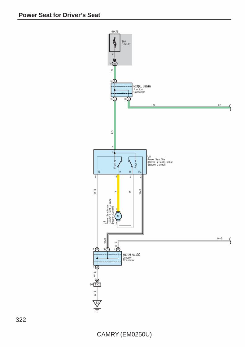
322
CAMRY (EM0250U)
Power Seat for Driver’s Seat
B
LG
W–B
W–BWW–B Y
LG
E2
B
A
U5
B
A
2
(BAT)
4 IO
30AP/SEAT
1
2
M
Rea
r
Fron
t
6
2
5
9
N27(A), U11(B)
B8
LG
E H R R1
4 B3
W–B
W–B
N27(A), U11(B)
10 EN2
W–B
JunctionConnector
JunctionConnector
Pow
er S
eat M
otor
( Driv
er'
s S
eat L
umba
rS
uppo
rt C
ontro
l)
W–B
LG
Power Seat SW(Driver' s Seat LumbarSupport Control)
U8
3
2145
B
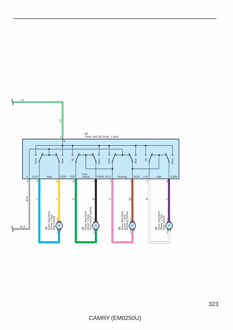
CAMRY (EM0250U)
323
4
SlideFrontVertical Reclining Lifter
Dow
n
Up
Rea
r
Fron
t
Dow
n
Up
Rea
r
Fron
tL G P W VBRBY
M
2
1
M
2
1
M
1
2
1
2
1
U4
9 6 10 5
U3
3 2 7 8
U2
U1
LG
M
B
SLDR FDWN RCLR LDWNLUPRCLFFUPSLDFE
W–B
Pow
er S
eat M
otor
( Driv
er'
s S
eat
Slid
e C
ontro
l)
Pow
er S
eat M
otor
( Driv
er'
s S
eat
Fron
t Ver
tical
Con
trol)
Pow
er S
eat M
otor
( Driv
er'
s S
eat
Rec
linin
g C
ontro
l)
Pow
er S
eat M
otor
( Driv
er'
s S
eat
Lifte
r C
ontro
l)
Power Seat SW (Driver' s Seat)U7
W–B
LG
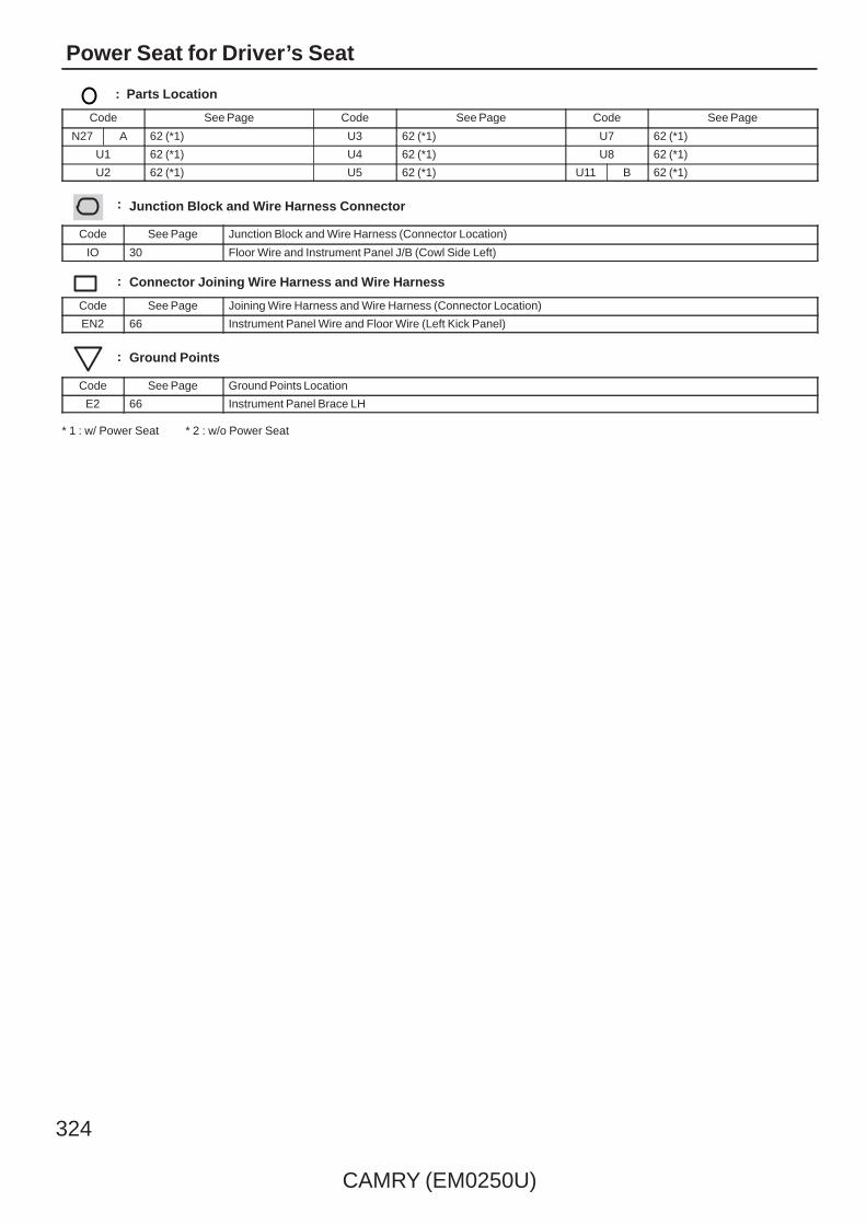
324
CAMRY (EM0250U)
Power Seat for Driver’s Seat
: Parts Location
Code See Page Code See Page Code See Page
N27 A 62 (*1) U3 62 (*1) U7 62 (*1)
U1 62 (*1) U4 62 (*1) U8 62 (*1)
U2 62 (*1) U5 62 (*1) U11 B 62 (*1)
: Junction Block and Wire Harness Connector
Code See Page Junction Block and Wire Harness (Connector Location)
IO 30 Floor Wire and Instrument Panel J/B (Cowl Side Left)
: Connector Joining Wire Harness and Wire Harness
Code See Page Joining Wire Harness and Wire Harness (Connector Location)
EN2 66 Instrument Panel Wire and Floor Wire (Left Kick Panel)
: Ground Points
Code See Page Ground Points Location
E2 66 Instrument Panel Brace LH
* 1 : w/ Power Seat * 2 : w/o Power Seat

CAMRY (EM0250U)
325
Memo

326
CAMRY (EM0250U)
Power Seat for Front Passenger’s Seat
2
(BAT)
30AP/SEAT
4
Slide Reclining
Rea
r
Fron
t
Rea
r
Fron
t
T1
1
2369
1
2
M
1
2
L Y P BR
T3
W–B
W–B
T8
M
EO21
EO210
W–B
IL11
A6
B8
GG
B
E
5
RCLF
A
SLDF
4
SLDR
B
RCLR
E3
O20(A), T18(B)
O20(A), T18(B)
JunctionConnector
JunctionConnector
Pow
er S
eat M
otor
( Fro
nt P
asse
nger
's
Sea
t Slid
e C
ontro
l)
Pow
er S
eat M
otor
( Fro
nt P
asse
nger
's
Sea
t Rec
linin
g C
ontro
l)Power Seat SW (Front Passenger' s Seat)
G

CAMRY (EM0250U)
327
: Parts Location
Code See Page Code See Page Code See Page
O20 A 62 (*1) T3 62 (*1) T18 B 62 (*1)
T1 62 (*1) T8 62 (*1)
: Junction Block and Wire Harness Connector
Code See Page Junction Block and Wire Harness (Connector Location)
IL 30 Instrument Panel Wire and Instrument Panel J/B (Cowl Side Left)
: Connector Joining Wire Harness and Wire Harness
Code See Page Joining Wire Harness and Wire Harness (Connector Location)
EO2 66 Instrument Panel Wire and Floor No.2 Wire (Right Kick Panel)
: Ground Points
Code See Page Ground Points Location
E3 66 Instrument Panel Right
* 1 : w/ Power Seat * 2 : w/o Power Seat

328
CAMRY (EM0250U)
Seat Heater
7
2
1 B
5 A
Sea
tC
ushi
on
Sea
tB
ack
E49
EO220 EN220
20AS–HTR
IM19
(IG)
A8
B6
3 6
5
BL P
P
N27
( A) ,
U11
( B)
E55
E2
4
W–B
W–B
IG
RH E LH
RH
Sid
eS
eat S
W
LH S
ide
Sea
t SW
A8
B6
P
L
O20
( A) ,
T18(
B)
Sea
tC
ushi
on
1
Junc
tion
Con
nect
or
Sea
t Hea
ter
SW
Junc
tion
Con
nect
or
Junc
tion
Con
nect
or
Sea
tB
ack
EN210
E3
A5
B110
EO2
1
L
2 2
W–B
W–B
W–B
W–B
W–B
W–B
W–B
JunctionConnector
O20(A), T18(B)
Sea
t Hea
ter
( RH
)T6 S
eat H
eate
r ( L
H)
U6
Junc
tion
Con
nect
or
N27
( A) ,
U11
( B)

CAMRY (EM0250U)
329
: Parts Location
Code See Page Code See Page Code See Page
E49 57 O20 A 62 (*1) U6 62 (*1)
E55 57 T6 62 (*1) U11 B 62 (*1)
N27 A 62 (*1) T18 B 62 (*1)
: Junction Block and Wire Harness Connector
Code See Page Junction Block and Wire Harness (Connector Location)
IM 30 Instrument Panel Wire and Instrument Panel J/B (Cowl Side Left)
: Connector Joining Wire Harness and Wire Harness
Code See Page Joining Wire Harness and Wire Harness (Connector Location)
EN2 66 Instrument Panel Wire and Floor Wire (Left Kick Panel)
EO2 66 Instrument Panel Wire and Floor No.2 Wire (Right Kick Panel)
: Ground Points
Code See Page Ground Points Location
E2 66 Instrument Panel Brace LH
E3 66 Instrument Panel Right
* 1 : w/ Power Seat * 2 : w/o Power Seat
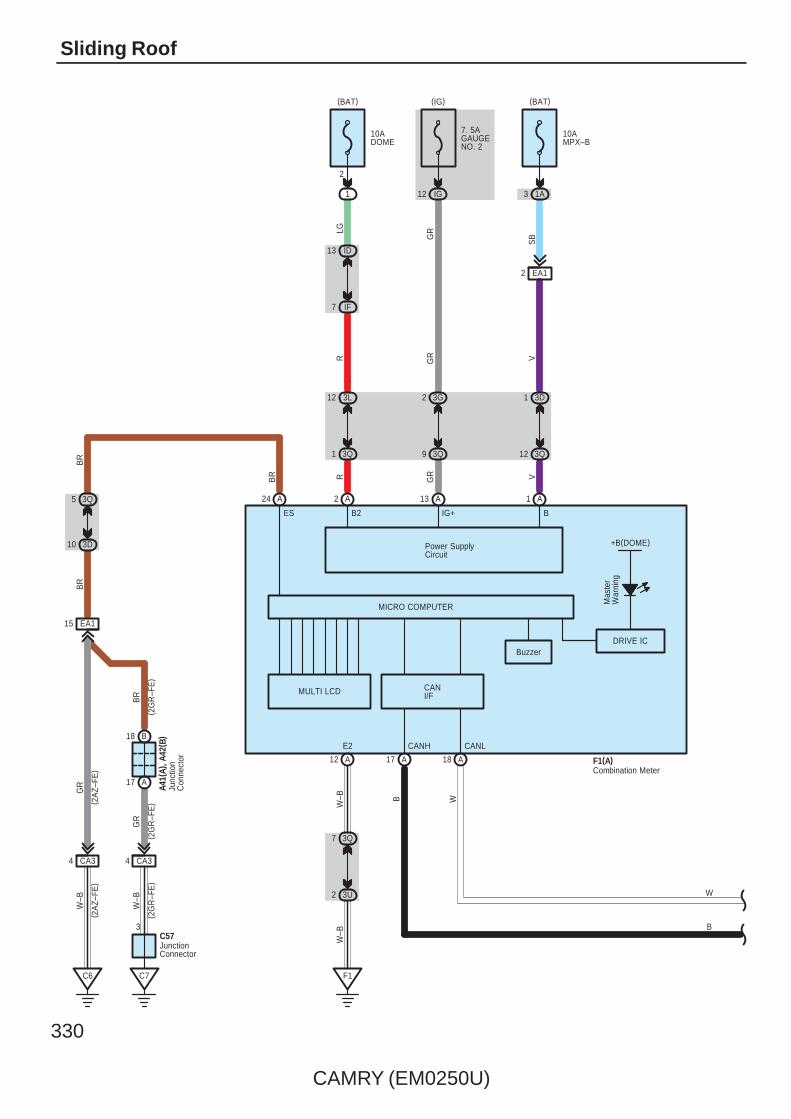
330
CAMRY (EM0250U)
Sliding Roof
W
( 2G
R–F
E)
BR
GR
BR
BR
C57
15 EA1
( 2A
Z–FE
)( 2
AZ–
FE)
( 2G
R–F
E)
( 2G
R–F
E)
A41(
A), A
42( B
)
GR
W–B
W–B
3
C7
4 CA3
17 A
18 B
C6
4 CA3
10 3D
5 3Q
B
DRIVE IC
+B(DOME)
MICRO COMPUTER
B2 B
Mas
ter
War
ning
17 A A18
1
V
IG+
A
1 3D
12 3Q
1A
10AMPX–B
(BAT)
2
RLG
A
12 3L
1 3Q
13 ID
7 IF
1
10ADOME
(BAT)
2
Power SupplyCircuit
13
GR
A
2 3G
9 3Q
12 IG
7. 5AGAUGENO. 2
(IG)
12 A
EA12
SB
3Q7
3U2
F1
W–B
W–B
CANH CANLE2
Junc
tion
Con
nect
or
JunctionConnector
F1(A)Combination Meter
W
B
R VGR
GR
3
Buzzer
CANI/F
ES
24
BR
A
MULTI LCD
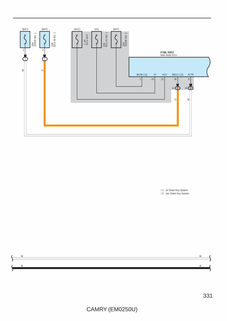
CAMRY (EM0250U)
331
(IG)(ACC)
7. 5
AE
CU
–AC
C
10A
EC
U IG
NO
. 1
15
IG
22
ACC
(BAT)
O
BECU (∗2)
26
10 ID
1
210
AE
CU
–B N
O. 1
25A
DO
OR
NO
. 1
2
1
(BAT)
ID16
W
ALTB
6
(BAT)
2
BATB (∗1)
25A
DO
OR
NO
. 2
E7(B), E8(C)Main Body ECU
W
B
W
B
∗ 1 : w/ Smart Key System∗ 2 : w/o Smart Key System
OW

332
CAMRY (EM0250U)
Sliding Roof
12
E2
IM9
GND2
4
W–B
W–B
2
13
24
EN2
N6(
A), (
B)
LL
DCTY
B
L
3O12
3F10
C10
LIN2
P
E7(B), E8(C)Main Body ECU
Doo
r C
ourte
sy S
W( D
river
's
Sid
e)
6
B
W BBW
CANHCANL
5 C6 C
W
E43(
B), E
44( C
)Ju
nctio
n C
onne
ctor
P
F1
W–B
W–B
∗ 3 : TMC Made∗ 4 : TMMK Made
W
B
FE314 FE313
(∗4)B1(∗3)A1
FE34
W–B
W–B
IF10
GND1
5
IR1
JunctionConnector
E4910
W–B
W–B
W–B
B2 B1
C1C2
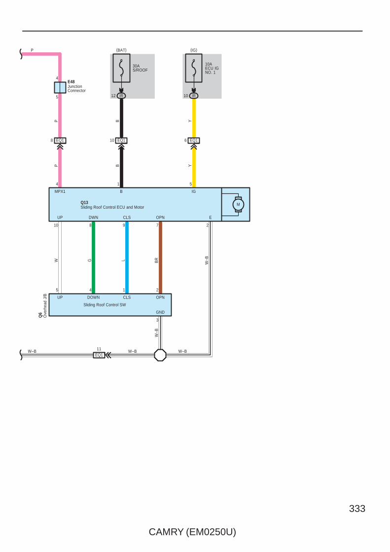
CAMRY (EM0250U)
333
5
4
JunctionConnector
E48
P
CLS
6 EQ1
10AECU IGNO. 1
IR10
Y
30AS/ROOF
IR12
EQ110EQ18
BP
Q13
UP DWN CLS OPN
(IG)
Q6
DOWNUP OPN
2145
E
BMPX1 IG
Ove
rhea
d J/
B
Sliding Roof Control ECU and Motor
(BAT)
M
BP
BRLGW
GND
3
Y
W–B
4 1 5
Sliding Roof Control SW
10 8 9 7 2
11EQ1
W–B W–B W–B
W–B

334
CAMRY (EM0250U)
Sliding Roof
: Parts Location
Code See Page Code See Page Code See Page
A41 A 59 E43 B 57N6
A 60
A42 B 59 E44 C 57N6
B 60
C57 51 (2GR–FE) E48 57 Q6 61
E7 B 56 E49 57 Q13 61
E8 C 56 F1 A 58
: Relay Blocks
Code See Page Relay Blocks (Relay Block Location)
1 22 Engine Room R/B (Engine Compartment Left)
: Junction Block and Wire Harness Connector
Code See Page Junction Block and Wire Harness (Connector Location)
1A 25 Engine Room Main Wire and Engine Room J/B (Engine Compartment Left)
3D
36 Instrument Panel Wire and J/B No.3 (Behind the Combination Meter)
3F
36 Instrument Panel Wire and J/B No.3 (Behind the Combination Meter)3G 36 Instrument Panel Wire and J/B No.3 (Behind the Combination Meter)
3L
36 Instrument Panel Wire and J/B No.3 (Behind the Combination Meter)
3O
3Q36 Instrument Panel No.2 Wire and J/B No.3 (Behind the Combination Meter)
3U36 Instrument Panel No.2 Wire and J/B No.3 (Behind the Combination Meter)
ID 30 Engine Room Main Wire and Instrument Panel J/B (Cowl Side Left)
IF 30
Instrument Panel Wire and Instrument Panel J/B (Cowl Side Left)IG 31
Instrument Panel Wire and Instrument Panel J/B (Cowl Side Left)IM
30
Instrument Panel Wire and Instrument Panel J/B (Cowl Side Left)
IR30
: Connector Joining Wire Harness and Wire Harness
Code See Page Joining Wire Harness and Wire Harness (Connector Location)
CA364 (2GR–FE)
Engine Wire and Engine Room Main Wire (Inside of the Engine Room R/B and Engine Room J/B)CA365 (2AZ–FE)
Engine Wire and Engine Room Main Wire (Inside of the Engine Room R/B and Engine Room J/B)
EA1 66 Instrument Panel Wire and Engine Room Main Wire (Left Kick Panel)
EN2 66 Instrument Panel Wire and Floor Wire (Left Kick Panel)
EQ1 66 Instrument Panel Wire and Roof Wire (Lower Part of Front Pillar LH)
FE3 66 Instrument Panel No.2 Wire and Instrument Panel Wire (Instrument Panel Center)
: Ground Points
Code See Page Ground Points Location
C6 65 (2AZ–FE) Cylinder Block
C7 64 (2GR–FE) Left Side of the Cylinder Block
E2 66 Instrument Panel Brace LH
F1 66 Instrument Panel Left

CAMRY (EM0250U)
335
Memo
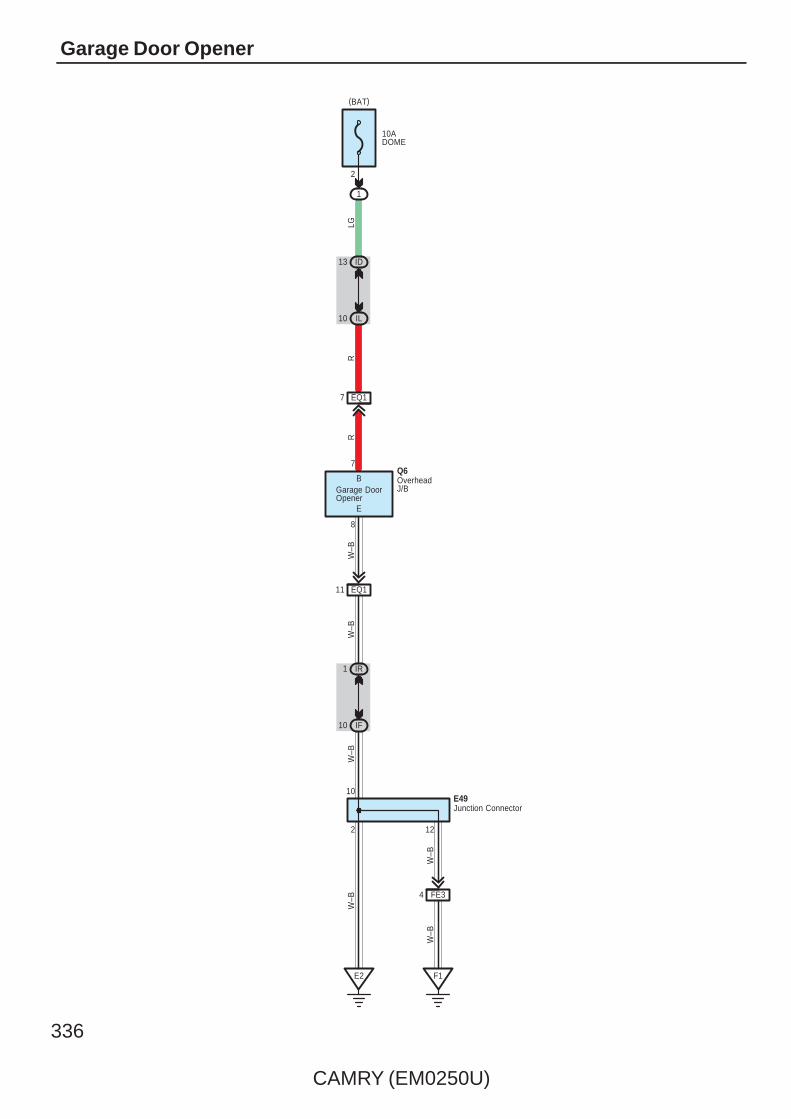
336
CAMRY (EM0250U)
Garage Door Opener
10ADOME
1
2
(BAT)
ID13
IL10
EQ17
EQ111
IR1
IF10
E2 F1
FE34
2
10
12
E
B
W–B
W–B
W–B
W–B
W–B
W–B
RR
LG
8
7
Garage DoorOpener
Junction ConnectorE49
OverheadJ/B
Q6

CAMRY (EM0250U)
337
: Parts Location
Code See Page Code See Page Code See Page
E49 57 Q6 61
: Relay Blocks
Code See Page Relay Blocks (Relay Block Location)
1 22 Engine Room R/B (Engine Compartment Left)
: Junction Block and Wire Harness Connector
Code See Page Junction Block and Wire Harness (Connector Location)
ID 30 Engine Room Main Wire and Instrument Panel J/B (Cowl Side Left)
IF
30 Instrument Panel Wire and Instrument Panel J/B (Cowl Side Left)IL 30 Instrument Panel Wire and Instrument Panel J/B (Cowl Side Left)
IR
30 Instrument Panel Wire and Instrument Panel J/B (Cowl Side Left)
: Connector Joining Wire Harness and Wire Harness
Code See Page Joining Wire Harness and Wire Harness (Connector Location)
EQ1 66 Instrument Panel Wire and Roof Wire (Lower Part of Front Pillar LH)
FE3 66 Instrument Panel No.2 Wire and Instrument Panel Wire (Instrument Panel Center)
: Ground Points
Code See Page Ground Points Location
E2 66 Instrument Panel Brace LH
F1 66 Instrument Panel Left

338
CAMRY (EM0250U)
Automatic Glare–Resistant EC Mirror
FE312
W–B
6 EQ1
E49
IG
4
E
1
10AECU IGNO. 1
IR10
W–B
Y
Q3
(IG)
11 EQ1
W–B
IR1
IF10
2
10
E2
W–B
W–B
F1
Y
4
Junc
tion
Con
nect
orIn
ner
Rea
rV
iew
Mirr
or
W–B

CAMRY (EM0250U)
339
: Parts Location
Code See Page Code See Page Code See Page
E49 57 Q3 61
: Junction Block and Wire Harness Connector
Code See Page Junction Block and Wire Harness (Connector Location)
IF30 Instrument Panel Wire and Instrument Panel J/B (Cowl Side Left)
IR30 Instrument Panel Wire and Instrument Panel J/B (Cowl Side Left)
: Connector Joining Wire Harness and Wire Harness
Code See Page Joining Wire Harness and Wire Harness (Connector Location)
EQ1 66 Instrument Panel Wire and Roof Wire (Lower Part of Front Pillar LH)
FE3 66 Instrument Panel No.2 Wire and Instrument Panel Wire (Instrument Panel Center)
: Ground Points
Code See Page Ground Points Location
E2 66 Instrument Panel Brace LH
F1 66 Instrument Panel Left
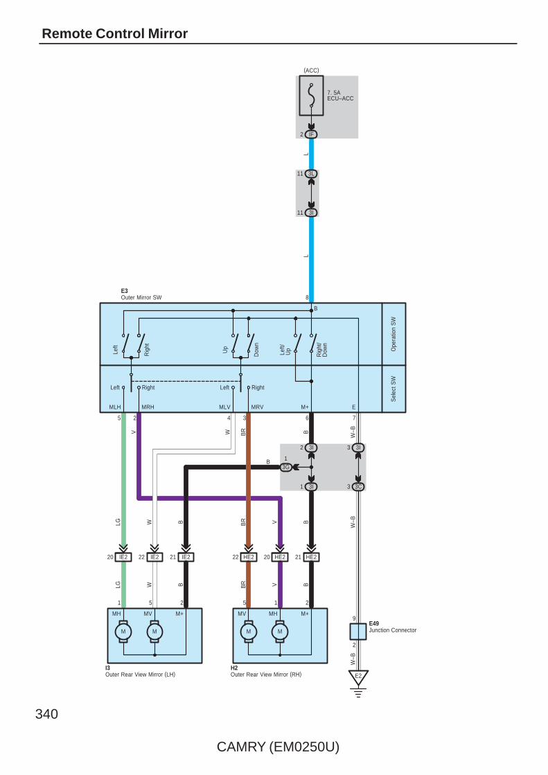
340
CAMRY (EM0250U)
Remote Control Mirror
1
LG
21 IE222 IE220
B
IE2
11 3I
(ACC)
7635 2 4
EM+MLVMLH MRH MRV
RightLeftLeft Right
8
E2
7. 5AECU–ACC
IF2
L
M
I3
L
1
M
HE222
H2
3C
HE220
3
HE221
MM
215251
MH MV
W–B
B
M+
VBR
E3
MV MH
W–BB
M+
VBR
BWLG
W–BBBRWV
3GB
W
11 3L
3I33I2
3I
B
Left
Rig
ht
Up
Dow
n
Left/
Up
Rig
ht/
Dow
n
9
2
E49
Ope
ratio
n S
WS
elec
t SW
Outer Mirror SW
Junction Connector
Outer Rear View Mirror (RH)Outer Rear View Mirror (LH)

CAMRY (EM0250U)
341
: Parts Location
Code See Page Code See Page Code See Page
E3 56 H2 61
E49 57 I3 61
: Junction Block and Wire Harness Connector
Code See Page Junction Block and Wire Harness (Connector Location)
3C
36 Instrument Panel Wire and J/B No.3 (Behind the Combination Meter)3G
36 Instrument Panel Wire and J/B No.3 (Behind the Combination Meter)3I
36 Instrument Panel Wire and J/B No.3 (Behind the Combination Meter)
3L
IF 30 Instrument Panel Wire and Instrument Panel J/B (Cowl Side Left)
: Connector Joining Wire Harness and Wire Harness
Code See Page Joining Wire Harness and Wire Harness (Connector Location)
HE2 66 Front Door RH Wire and Instrument Panel Wire (Right Kick Panel)
IE2 66 Front Door LH Wire and Instrument Panel Wire (Left Kick Panel)
: Ground Points
Code See Page Ground Points Location
E2 66 Instrument Panel Brace LH
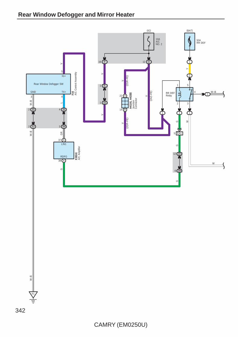
342
CAMRY (EM0250U)
Rear Window Defogger and Mirror Heater
12 ID
14 B
22
(BAT)
50ARR DEF
1 1
A
10AA/CNO. 2
3D
GG
6 3M
12
W
5 EA1
G
( 2G
R–F
E)
VV
( 2A
Z–FE
)
V
4
( 2G
R–F
E)
1
Y
5
2
RR DEFRelay
3
(IG)
1
1
1
1
Junc
tion
Con
nect
or
A41(
A), A
42( B
)
RDFG
G
38 A
GR
L
TX+
4
A
GND
3
W–B
W–B
LIN1
3 3M
4 3S
IG+
5
3S2
3U2
F1
37
IF16V
W–B
3L1
3S1V
V
A/C
Am
plifi
erE3
8(A)
Rear Window Defogger SW
A/C
Con
trol A
ssem
bly
F16 W–B
W
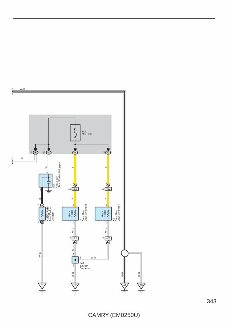
CAMRY (EM0250U)
343
10AMIR HTR
IO13 IK1
1
IE210 HE210
IE217 HE217
E2
N19
( A) ,
P1( B
)
I3 H2
YY
B Y Y
W–B
W–B
W–B
4 4
3 3
12 IJ
5 W–BW–B
P1
1 B
1 A
13
2
W
E49
2
W–B
A1
W–B
N18
JunctionConnector
Out
er R
ear
Vie
w M
irror
(R
H)
Out
er R
ear
Vie
w M
irror
(LH
)
Noi
se F
ilter
( Rea
r W
indo
w D
efog
ger)
Rea
r W
indo
wD
efog
ger
Mirr
orH
eate
r
Mirr
orH
eate
r
IB2
W–B
W
A3
W–B

344
CAMRY (EM0250U)
Rear Window Defogger and Mirror Heater
: Parts Location
Code See Page Code See Page Code See Page
A41 A 59 F16 58 N19 A 60
A42 B 59 H2 61 P1 B 60
E38 A 57 I3 61
E49 57 N18 60
: Relay Blocks
Code See Page Relay Blocks (Relay Block Location)
1 22 Engine Room R/B (Engine Compartment Left)
: Junction Block and Wire Harness Connector
Code See Page Junction Block and Wire Harness (Connector Location)
3D
36 Instrument Panel Wire and J/B No.3 (Behind the Combination Meter)3L 36 Instrument Panel Wire and J/B No.3 (Behind the Combination Meter)
3M
36 Instrument Panel Wire and J/B No.3 (Behind the Combination Meter)
3S36 Instrument Panel No.2 Wire and J/B No.3 (Behind the Combination Meter)
3U36 Instrument Panel No.2 Wire and J/B No.3 (Behind the Combination Meter)
IB30 Engine Room Main Wire and Instrument Panel J/B (Cowl Side Left)
ID30 Engine Room Main Wire and Instrument Panel J/B (Cowl Side Left)
IF
30 Instrument Panel Wire and Instrument Panel J/B (Cowl Side Left)IJ 30 Instrument Panel Wire and Instrument Panel J/B (Cowl Side Left)
IK
30 Instrument Panel Wire and Instrument Panel J/B (Cowl Side Left)
IO 30 Floor Wire and Instrument Panel J/B (Cowl Side Left)
: Connector Joining Wire Harness and Wire Harness
Code See Page Joining Wire Harness and Wire Harness (Connector Location)
EA1 66 Instrument Panel Wire and Engine Room Main Wire (Left Kick Panel)
HE2 66 Front Door RH Wire and Instrument Panel Wire (Right Kick Panel)
IE2 66 Front Door LH Wire and Instrument Panel Wire (Left Kick Panel)
: Ground Points
Code See Page Ground Points Location
A164 (2GR–FE)
Front Left FenderA165 (2AZ–FE)
Front Left Fender
E2 66 Instrument Panel Brace LH
F1 66 Instrument Panel Left
P1 67 Right Rear Quarter Panel

CAMRY (EM0250U)
345
Memo

346
CAMRY (EM0250U)
Navigation System and Audio System with 8 Speaker
7. 5ARADIONO. 2
IF12
(ACC)
15ARADIONO. 1
1
(BAT)
25AAMP
1
(BAT)
EA18 EA1173L6
3U6 3T6
11 E12 E13 E5 D15 D11 D
IE15 IE19
L
1
L–Y
D
L–Y
BR
GR
GR
12 B
7
GR
GR
GR
GR
F25
GR
GR
GR
12
A1 A5
B7 B8 B22 B23
C1 C2A7 A8
B ACC ATX– ATX+ SLD1 IVO– IVO+
+B +B2 WFL– WFL+FL– FL+
ACC TX– TX+ INT– INT+
G R
( Shi
elde
d)
G R
V P
V P
V P
V P
HE15 HE19
1
C3 C9
WFR– WFR+L LG
L LG
L LG
2
L–Y
2 1 2 1
I1F21 H1Tweeter (Front LH)
Junction Connector
Speaker(Front Door RH)
Speaker(Front Door LH)
2 2
F9(D), F10(E), F12(G), F13(H), F14(I)Navigation Receiver Assembly
F18(A), F19(B), F20(C)Stereo Component Amplifier
5 FE3 9 FE3
1 FE3 6 FE3 2 FE3 7 FE3

CAMRY (EM0250U)
347
9 D18 D8 D10
F15
D7 D D19
B
1O
B1 B6 B5 4 B B3 B2
13 D
9 A A3 C10
18 G
C4
12
C12
G
C5 A4 A10
ANTMUTE SLD R+ SGNDR– L+ TSW–L–
RL– RL+ SL– SL+ SR– SR+ RR– RR+
MUTE SLD R+ R– L+ L–
O
( Shi
elde
d)
R G B W
Y B BR
G–W Y L W R
9 OF1
P
OF118 OF12 OF111
3 1 4 2
Y B BR
G–W
O14
OF11 OF110 OF18 OF117
Y L W R
4 2 3 1
O15
F9(D), F10(E), F12(G), F13(H), F14(I)
F18(A), F19(B), F20(C)
Antenna Amplifier
Stereo Component Amplifier
Navigation Receiver Assembly
Speaker (Rear LH) Speaker (Rear RH)
– + WF1– WF1+ WF2– WF2+ – +

348
CAMRY (EM0250U)
Navigation System and Audio System with 8 Speaker
AUXO
F17
1
3U8
3D7
2 3 4
R G G
ALO ARO ASGN
( Shi
elde
d)
BR
BR
H3
RR
B11
6 I5 I2 I3 I
ADPGVA–VAR+VAL+SPD
GNDE
BR
BR
6 C7 C
SPD
F3
V
5 H
REV
12
A6 A2
FR– FR+
L LG
F18(A), F19(B), F20(C)
F9(D), F10(E), F12(G), F13(H), F14(I)
F23
Stereo Jack Adapter
Stereo Component Amplifier
Tweeter (Front RH)
Navigation Receiver Assembly
3U9
3P3
VV
3U10
V
R
GR
R
OR
P
E48
10AGAUGENO. 1
IH16
RL
8
2 A1 B
2
R
RB
B
(IG)
20 CA2
2
6 AE3
A
10 CA2
1
Junc
tion
Con
nect
or
L
(2GR–FE)(2AZ–FE)
Park/NeutralPosition SW
C1(A), (B)
EA114
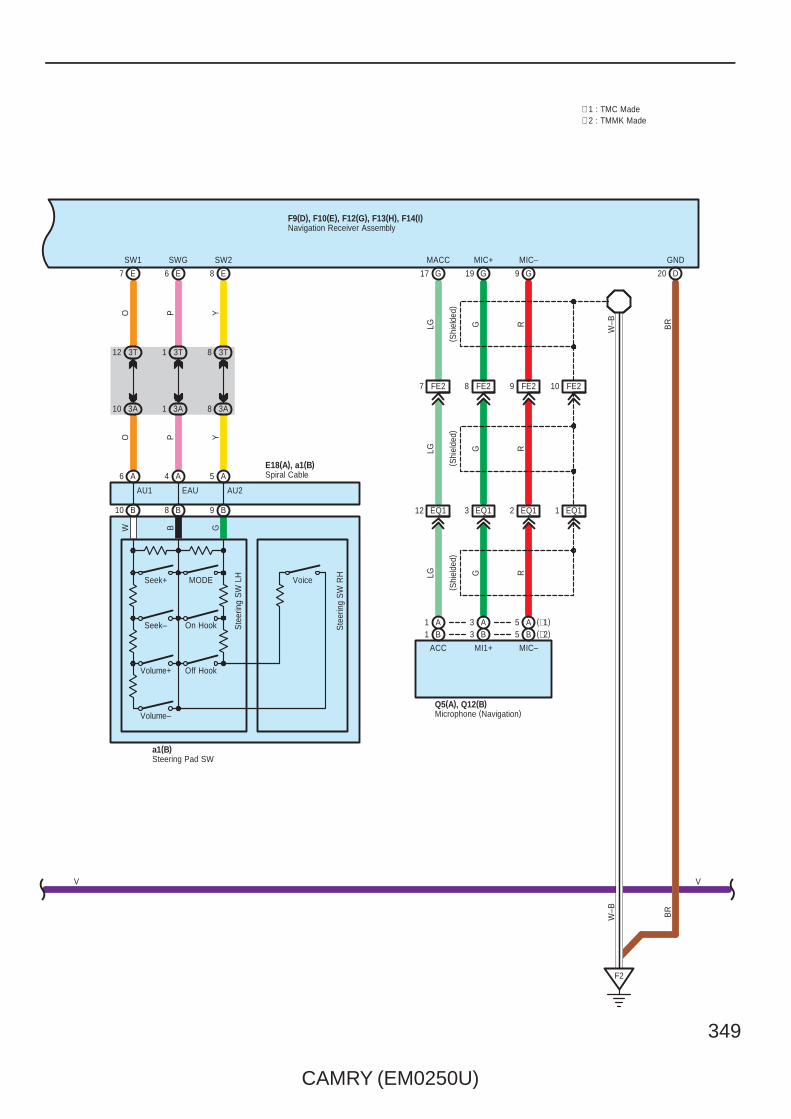
CAMRY (EM0250U)
349
3T1
3A1
3T12
3A10
3T8
3A8
YO PPO Y
BR
20 DE87 E 6 E
SW2SW1 SWG GND
FE27 FE28 FE29 FE210
EQ112 EQ13 EQ12 EQ11
W–B
F2
G17
MACC
G19
MIC+
G9
MIC–
LG G R
( Shi
elde
d)
W–B
BR
LG G R
LG G R
ACC MI1+ MIC–
Q5(A), Q12(B)
( Shi
elde
d)
Microphone (Navigation)
A6 A4 A5
AU1 EAU
B10
E18(A), a1(B)Spiral Cable
B8 B9
a1(B)Steering Pad SW
Seek–
Volume+
Volume–
MODESeek+
Ste
erin
g S
W L
H
AU2
Voice
On Hook
Off Hook
GBW
Ste
erin
g S
W R
H
F9(D), F10(E), F12(G), F13(H), F14(I)Navigation Receiver Assembly
V V
( Shi
elde
d)
(∗2)B5B3B1A1 A3 (∗1)A5
∗ 1 : TMC Made∗ 2 : TMMK Made

350
CAMRY (EM0250U)
Navigation System and Audio System with 8 Speaker
MICRO COMPUTER
BB2
E2
W–B
W–B
GR
BR
A41(
A), A
42( B
)
C57
( ∗6)
( ∗6)
ES
( ∗7)
(∗6)
(IG)
12 A
EA12
SB
3Q7
3U2
F1
W–B
W–B
3Q5
3D10
CA34
C6
15EA1
GR(∗7)
A17
B18
CA34BR(∗6)
C7
GR
3
V
F1( A
) , F2
( B)
A24
1
V
IG+
A
1 3D
12 3Q
10A
MP
X–B
(BAT)
2
RLG
7. 5
AG
AU
GE
NO
. 2
IG12
3Q9
3G2
A
GR
GR
13
Power SupplyCircuit
2
(BAT)
10A
DO
ME
12
1
IF7
ID13
3Q
A
1
3L
R
Junc
tion
Con
nect
or
Junc
tion
Con
nect
or
Com
bina
tion
Met
er
∗ 5 : w/o VSC∗ 4 : w/ VSC TMMK Made
8 C (∗5)(∗4)B8(∗3)A19
C19B29A5
C17B27A6
C7B7A20
C9B9A17
C10B10A3
C6B6A4
C5B5A18
Speed Sensors
LG V P L R L B W
(∗3)A12(∗4)B33(∗5)C23
FL+ FL– FR+ FR– RL+ RL– RR+ RR–
SP1
IG2
14 B
SI
3P11
3D3
AE66
WW
BR
W
IG2
∗ 3 : w/ VSC TMC Made
Ski
d C
ontro
l EC
U w
ith A
ctua
tor
A25(
C) ,
A26(
A), A
60( B
)
BR
V
+S
B12
V
∗ 6 : 2GR–FE∗ 7 : 2AZ–FE
1A3
Spe
edom
eter
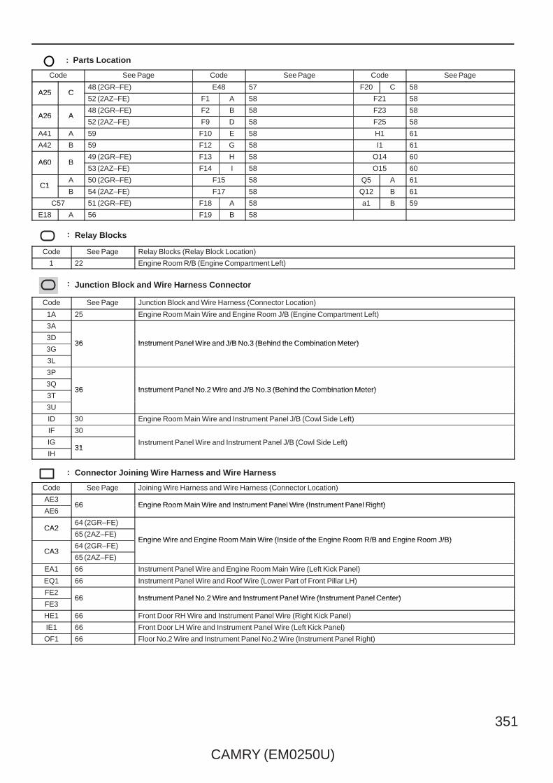
CAMRY (EM0250U)
351
: Parts Location
Code See Page Code See Page Code See Page
A25 C48 (2GR–FE) E48 57 F20 C 58
A25 C52 (2AZ–FE) F1 A 58 F21 58
A26 A48 (2GR–FE) F2 B 58 F23 58
A26 A52 (2AZ–FE) F9 D 58 F25 58
A41 A 59 F10 E 58 H1 61
A42 B 59 F12 G 58 I1 61
A60 B49 (2GR–FE) F13 H 58 O14 60
A60 B53 (2AZ–FE) F14 I 58 O15 60
C1A 50 (2GR–FE) F15 58 Q5 A 61
C1B 54 (2AZ–FE) F17 58 Q12 B 61
C57 51 (2GR–FE) F18 A 58 a1 B 59
E18 A 56 F19 B 58
: Relay Blocks
Code See Page Relay Blocks (Relay Block Location)
1 22 Engine Room R/B (Engine Compartment Left)
: Junction Block and Wire Harness Connector
Code See Page Junction Block and Wire Harness (Connector Location)
1A 25 Engine Room Main Wire and Engine Room J/B (Engine Compartment Left)
3A
36 Instrument Panel Wire and J/B No.3 (Behind the Combination Meter)3D
36 Instrument Panel Wire and J/B No.3 (Behind the Combination Meter)3G
36 Instrument Panel Wire and J/B No.3 (Behind the Combination Meter)
3L
3P
36 Instrument Panel No.2 Wire and J/B No.3 (Behind the Combination Meter)3Q
36 Instrument Panel No.2 Wire and J/B No.3 (Behind the Combination Meter)3T
36 Instrument Panel No.2 Wire and J/B No.3 (Behind the Combination Meter)
3U
ID 30 Engine Room Main Wire and Instrument Panel J/B (Cowl Side Left)
IF 30
Instrument Panel Wire and Instrument Panel J/B (Cowl Side Left)IG31
Instrument Panel Wire and Instrument Panel J/B (Cowl Side Left)
IH31
Instrument Panel Wire and Instrument Panel J/B (Cowl Side Left)
: Connector Joining Wire Harness and Wire Harness
Code See Page Joining Wire Harness and Wire Harness (Connector Location)
AE366 Engine Room Main Wire and Instrument Panel Wire (Instrument Panel Right)
AE666 Engine Room Main Wire and Instrument Panel Wire (Instrument Panel Right)
CA264 (2GR–FE)
Engine Wire and Engine Room Main Wire (Inside of the Engine Room R/B and Engine Room J/B)
CA265 (2AZ–FE)
Engine Wire and Engine Room Main Wire (Inside of the Engine Room R/B and Engine Room J/B)
CA364 (2GR–FE)
Engine Wire and Engine Room Main Wire (Inside of the Engine Room R/B and Engine Room J/B)
CA365 (2AZ–FE)
EA1 66 Instrument Panel Wire and Engine Room Main Wire (Left Kick Panel)
EQ1 66 Instrument Panel Wire and Roof Wire (Lower Part of Front Pillar LH)
FE266 Instrument Panel No.2 Wire and Instrument Panel Wire (Instrument Panel Center)
FE366 Instrument Panel No.2 Wire and Instrument Panel Wire (Instrument Panel Center)
HE1 66 Front Door RH Wire and Instrument Panel Wire (Right Kick Panel)
IE1 66 Front Door LH Wire and Instrument Panel Wire (Left Kick Panel)
OF1 66 Floor No.2 Wire and Instrument Panel No.2 Wire (Instrument Panel Right)

352
CAMRY (EM0250U)
Navigation System and Audio System with 8 Speaker
: Ground Points
Code See Page Ground Points Location
C6 65 (2AZ–FE) Cylinder Block
C7 64 (2GR–FE) Left Side of the Cylinder Block
F1 66 Instrument Panel Left
F2 66 Instrument Panel Brace RH
F3 66 Under the Front Passenger’s Seat

CAMRY (EM0250U)
353
Memo

354
CAMRY (EM0250U)
Audio System with 8 Speaker without Navigation
7. 5ARADIONO. 2
IF12
(ACC)
15ARADIONO. 1
1
(BAT)
25AAMP
1
(BAT)
EA18 EA1177
3L6
3U6
D
3T6
12
5
5 D16 15 D1 D
IE15 IE19
L5
L–Y
F
L
BR
GR
GR
12 B
7
L–Y
GR
GR
GR
F25
GR
GR
GR
12
A1 A5
B7 B8
F
GR
ACCACC
B1
C1 C2A7 A8 9 A A3 C10 C4
+B B ATX– ATX+
GR
D
MUTE
+B +B2 WFL– WFL+FL– FL+ RL– RL+ SL– SL+
ACC TX– TX+
11
MUTEG R O
V P
V P
V P
V P
Y B BR
G–W
9 OF1 OF118 OF12 OF111
3 1 4 2
Y B BR
G–W
O14
L–Y
F18(A), F19(B), F20(C)
9
13 10
GR
11L–
Y
F25
2 1 2 1
I1F21
Stereo Component Amplifier
Tweeter(Front LH)
JunctionConnector
Junction Connector
Speaker(Front Door LH)
Speaker (Rear LH)
2 2
F8(C), F11(F), F26(D)Radio Receiver Assembly
5 FE3 9 FE3
1 FE3 6 FE3
– + WF1– WF1+
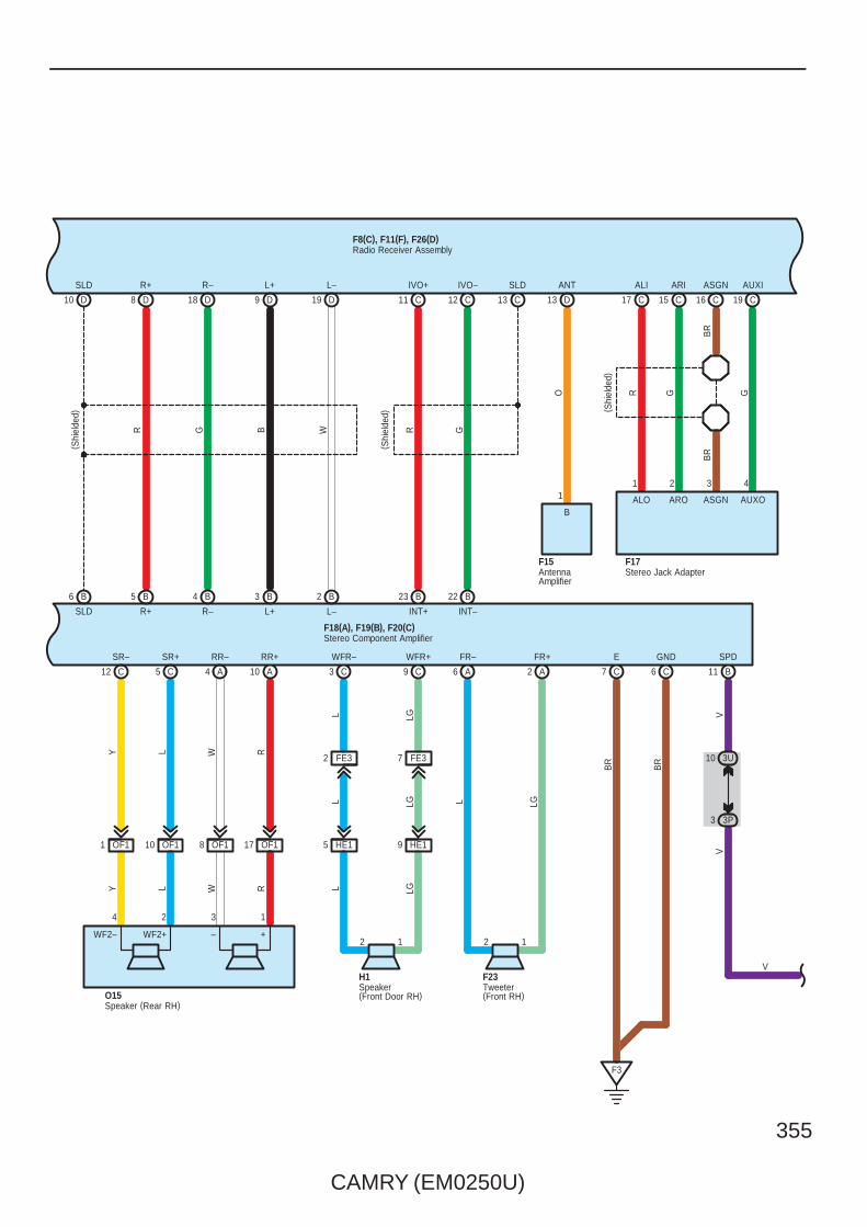
CAMRY (EM0250U)
355
9 D
AUXO
18 D
F17
8 D10
F15
D
1 2 3 4
R G
2
G
ALO ARO ASGN
( Shi
elde
d)
BR
BR
D19
B
1
O
B6 B5 4 B B3 B2
13 D 19 C16 C15 C17 C
C12 C5 A4 A10
ANT AUXIASGNARIALISLD R+ R– L+ L–
GNDEB
R
BR
SR–
6
SR+
C
RR– RR+
7 C
SLD R+ R– L+ L–
( Shi
elde
d)
F3
R G B W
Y L W R
12
OF11 OF110 OF18 OF117
Y L W R
4 2 3 1
O15
HE15 HE19
1
C3 C9 A6 A2
WFR– WFR+ FR– FR+
L LG
L LG
L LG
L LG
F8(C), F11(F), F26(D)
H1 F23
AntennaAmplifier
Stereo Jack Adapter
Tweeter(Front RH)
Radio Receiver Assembly
Speaker(Front Door RH)
Speaker (Rear RH)
F18(A), F19(B), F20(C)Stereo Component Amplifier
B11
SPD
3U10
3P3
VV
V
2 FE3 7 FE3
C11 C12 C13
B23 B22
SLDIVO–IVO+
R G
INT+ INT–
WF2– WF2+ – +
( Shi
elde
d)

356
CAMRY (EM0250U)
Audio System with 8 Speaker without Navigation
F2
BR
14 F
BR
GND GND
D20
BR
FE27 FE28 FE29 FE210
EQ112 EQ13 EQ12 EQ11
W–B
F7
MCVD
F2
MIC+
F1
MIC–
LG G R
( Shi
elde
d)
W–B
BR
LG G R
LG G R
ACC MI1+ MIC–
Q5(A), Q12(B)
( Shi
elde
d)( S
hiel
ded)
F8(C), F11(F), F26(D)Radio Receiver Assembly
Microphone (Navigation)
3T1
3A1
3T12
3A10
3T8
3A8
YO PPO Y
C87 C 6 C
SW2SW1 SWG
A6 A4 A5
AU1 EAU
B10
E18(A), a1(B)Spiral Cable
B8 B9
a1(B)Steering Pad SW
Seek–
Volume+
Volume–
MODESeek+
Ste
erin
g S
W L
H
AU2
Voice
On Hook
Off Hook
GBW
Ste
erin
g S
W R
H
V V
B1A1
B3A3
(∗2)B5(∗1)A5

CAMRY (EM0250U)
357
MICRO COMPUTER
BB2
E2
W–B
W–B
GR
BR
A41(
A), A
42( B
)
C57
( ∗6)
( ∗6)
ES
( ∗7)
(∗6)
(IG)
12 A
EA12
SB
3Q7
3U2
F1
W–B
W–B
3Q5
3D10
CA34
C6
15EA1
GR(∗7)
A17
B18
CA34BR(∗6)
C7
GR
3
V
F1( A
) , F2
( B)
∗ 2 : TMMK Made∗ 1 : TMC Made
A24
1
V
IG+
A
1 3D
12 3Q10
A M
PX
–B
(BAT)
2
RLG
7. 5
AG
AU
GE
NO
. 2
IG12
3Q9
3G2
A
GR
GR
13
Power SupplyCircuit
2
(BAT)
10A
DO
ME
12
1
IF7
ID13
3Q
A
1
3L
R
Junc
tion
Con
nect
or
Junc
tion
Con
nect
or
Com
bina
tion
Met
er
∗ 5 : w/o VSC∗ 4 : w/ VSC TMMK Made
8 C (∗5)(∗4)B8(∗3)A19
C19B29A5
C17B27A6
C7B7A20
C9B9A17
C10B10A3
C6B6A4
C5B5A18
Speed Sensors
LG V P L R L B W
(∗3)A12(∗4)B33(∗5)C23
FL+ FL– FR+ FR– RL+ RL– RR+ RR–
SP1
IG2
14 B
SI
3P11
3D3
AE66
WW
BR
W
IG2
∗ 3 : w/ VSC TMC Made
Ski
d C
ontro
l EC
U w
ith A
ctua
tor
A25(
C) ,
A26(
A), A
60( B
)
BR
V
+S
B12
V
∗ 6 : 2GR–FE∗ 7 : 2AZ–FE
1A3
Spe
edom
eter

358
CAMRY (EM0250U)
Audio System with 8 Speaker without Navigation
: Parts Location
Code See Page Code See Page Code See Page
A25 C48 (2GR–FE) F1 A 58 F23 58
A25 C52 (2AZ–FE) F2 B 58 F25 58
A26 A48 (2GR–FE) F8 C 58 F26 D 58
A26 A52 (2AZ–FE) F11 F 58 H1 61
A41 A 59 F15 58 I1 61
A42 B 59 F17 58 O14 60
A60 B49 (2GR–FE) F18 A 58 O15 60
A60 B53 (2AZ–FE) F19 B 58 Q5 A 61
C57 51 (2GR–FE) F20 C 58 Q12 B 61
E18 A 56 F21 58 a1 B 59
: Relay Blocks
Code See Page Relay Blocks (Relay Block Location)
1 22 Engine Room R/B (Engine Compartment Left)
: Junction Block and Wire Harness Connector
Code See Page Junction Block and Wire Harness (Connector Location)
1A 25 Engine Room Main Wire and Engine Room J/B (Engine Compartment Left)
3A
36 Instrument Panel Wire and J/B No.3 (Behind the Combination Meter)3D
36 Instrument Panel Wire and J/B No.3 (Behind the Combination Meter)3G
36 Instrument Panel Wire and J/B No.3 (Behind the Combination Meter)
3L
3P
36 Instrument Panel No.2 Wire and J/B No.3 (Behind the Combination Meter)3Q
36 Instrument Panel No.2 Wire and J/B No.3 (Behind the Combination Meter)3T
36 Instrument Panel No.2 Wire and J/B No.3 (Behind the Combination Meter)
3U
ID 30 Engine Room Main Wire and Instrument Panel J/B (Cowl Side Left)
IF 30Instrument Panel Wire and Instrument Panel J/B (Cowl Side Left)
IG 31Instrument Panel Wire and Instrument Panel J/B (Cowl Side Left)
: Connector Joining Wire Harness and Wire Harness
Code See Page Joining Wire Harness and Wire Harness (Connector Location)
AE6 66 Engine Room Main Wire and Instrument Panel Wire (Instrument Panel Right)
CA364 (2GR–FE)
Engine Wire and Engine Room Main Wire (Inside of the Engine Room R/B and Engine Room J/B)CA365 (2AZ–FE)
Engine Wire and Engine Room Main Wire (Inside of the Engine Room R/B and Engine Room J/B)
EA1 66 Instrument Panel Wire and Engine Room Main Wire (Left Kick Panel)
EQ1 66 Instrument Panel Wire and Roof Wire (Lower Part of Front Pillar LH)
FE266 Instrument Panel No.2 Wire and Instrument Panel Wire (Instrument Panel Center)
FE366 Instrument Panel No.2 Wire and Instrument Panel Wire (Instrument Panel Center)
HE1 66 Front Door RH Wire and Instrument Panel Wire (Right Kick Panel)
IE1 66 Front Door LH Wire and Instrument Panel Wire (Left Kick Panel)
OF1 66 Floor No.2 Wire and Instrument Panel No.2 Wire (Instrument Panel Right)
: Ground Points
Code See Page Ground Points Location
C6 65 (2AZ–FE) Cylinder Block
C7 64 (2GR–FE) Left Side of the Cylinder Block
F1 66 Instrument Panel Left
F2 66 Instrument Panel Brace RH
F3 66 Under the Front Passenger’s Seat

CAMRY (EM0250U)
359
Memo

360
CAMRY (EM0250U)
Audio System with 6 Speaker
15ARADIONO. 1
1
(BAT)
7. 5ARADIONO. 2
IF12
(ACC)
EA117 3L6
3T6
F2
IE19IE15
OF19 OF118 OF18 OF117
HE15 HE19
1
A4 A3
A7 A6 2 A B6 B2 B3 B1 A5 A1
LL–
YL–
Y
GR
GR
B ACC
BR
GND FL– FL+ RL– RL+ RR– RR+ FR– FR+
2
V P L LG
PV L LG
L LGV PPV L LG
Y B W R
Y B W R
F22
F24
4 2 4 2
13 3 1
BR
F6(A), F7(B), F8(C)
2 1 2 1
I1 O12
2 1
H1O13
Twee
ter
( Fro
nt L
H)
Twee
ter
( Fro
nt R
H)
Radio Receiver Assembly
Speaker(Front Door RH)
Speaker(Front Door LH)
Speaker(Rear LH)
Speaker(Rear RH)
2
TWL– TWL+
– +
TWR– TWR+
– +
1 FE3 6 FE3
9 FE3
2 FE3 7 FE3

CAMRY (EM0250U)
361
F15Antenna Amplifier
C19 C15 C17 C16
1
AUXI ARI ALI ASGN
AUXO ARO ALO ASGN
G O R
F17
4 2 1 3B
RB
R
( Shi
elde
d)
B
ANT
O8 A
Stereo Jack Adapter
3T1
3A1
3T12
3A10
3T8
3A8
YO PPO Y
C87 C 6 C
SW2SW1 SWG
A6 A4 A5
AU1 EAU
B10
E18(A), a1(B)Spiral Cable
B8 B9
a1(B)Steering Pad SW
Seek–
Volume+
Volume–
MODESeek+
Ste
erin
g S
W L
H
AU2
Voice
On Hook
Off Hook
GBW
Ste
erin
g S
W R
H
SPD
C3
V
3T9
3P3
VV
F6(A), F7(B), F8(C)Radio Receiver Assembly
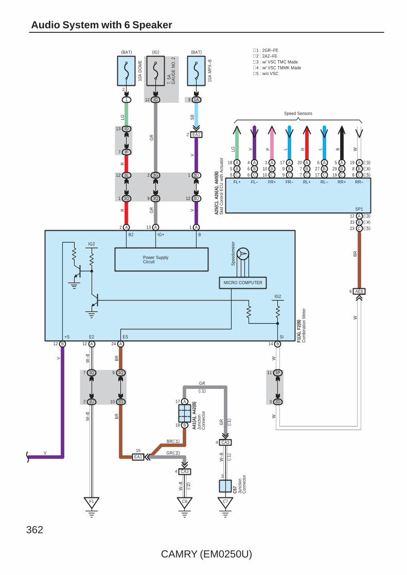
362
CAMRY (EM0250U)
Audio System with 6 Speaker
V
MICRO COMPUTER
BB2
E2
W–B
W–B
GR
BR
A41(
A), A
42( B
)
C57
( ∗1)
( ∗1)
ES
( ∗2)
(∗1)
(IG)
12 A
EA12
SB
3Q7
3U2
F1
W–B
W–B
3Q5
3D10
CA34
C6
15EA1
GR(∗2)
A17
B18
CA34BR(∗1)
C7
GR
3
V
F1( A
) , F2
( B)
A24
1
V
IG+
A
1 3D
12 3Q
10A
MP
X–B
(BAT)
2
RLG
7. 5
AG
AU
GE
NO
. 2
IG12
3Q9
3G2
A
GR
GR
13
Power SupplyCircuit
2
(BAT)
10A
DO
ME
12
1
IF7
ID13
3Q
A
1
3L
R
Junc
tion
Con
nect
or
Junc
tion
Con
nect
or
Com
bina
tion
Met
er
∗ 5 : w/o VSC∗ 4 : w/ VSC TMMK Made
8 C (∗5)(∗4)B8(∗3)A19
C19B29A5
C17B27A6
C7B7A20
C9B9A17
C10B10A3
C6B6A4
C5B5A18
Speed Sensors
LG V P L R L B W
(∗3)A12(∗4)B33(∗5)C23
FL+ FL– FR+ FR– RL+ RL– RR+ RR–
SP1
IG2
14 B
SI
3P11
3D3
AE66
WW
BR
W
IG2
∗ 3 : w/ VSC TMC Made
Ski
d C
ontro
l EC
U w
ith A
ctua
tor
A25(
C) ,
A26(
A), A
60( B
)
BR
V
+S
B12
1A3
∗ 2 : 2AZ–FE∗ 1 : 2GR–FE
Spe
edom
eter
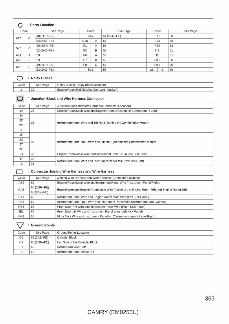
CAMRY (EM0250U)
363
: Parts Location
Code See Page Code See Page Code See Page
A25 C48 (2GR–FE) C57 51 (2GR–FE) F17 58
A25 C52 (2AZ–FE) E18 A 56 F22 58
A26 A48 (2GR–FE) F1 A 58 F24 58
A26 A52 (2AZ–FE) F2 B 58 H1 61
A41 A 59 F6 A 58 I1 61
A42 B 59 F7 B 58 O12 60
A60 B49 (2GR–FE) F8 C 58 O13 60
A60 B53 (2AZ–FE) F15 58 a1 B 59
: Relay Blocks
Code See Page Relay Blocks (Relay Block Location)
1 22 Engine Room R/B (Engine Compartment Left)
: Junction Block and Wire Harness Connector
Code See Page Junction Block and Wire Harness (Connector Location)
1A 25 Engine Room Main Wire and Engine Room J/B (Engine Compartment Left)
3A
36 Instrument Panel Wire and J/B No.3 (Behind the Combination Meter)3D
36 Instrument Panel Wire and J/B No.3 (Behind the Combination Meter)3G
36 Instrument Panel Wire and J/B No.3 (Behind the Combination Meter)
3L
3P
36 Instrument Panel No.2 Wire and J/B No.3 (Behind the Combination Meter)3Q
36 Instrument Panel No.2 Wire and J/B No.3 (Behind the Combination Meter)3T
36 Instrument Panel No.2 Wire and J/B No.3 (Behind the Combination Meter)
3U
ID 30 Engine Room Main Wire and Instrument Panel J/B (Cowl Side Left)
IF 30Instrument Panel Wire and Instrument Panel J/B (Cowl Side Left)
IG 31Instrument Panel Wire and Instrument Panel J/B (Cowl Side Left)
: Connector Joining Wire Harness and Wire Harness
Code See Page Joining Wire Harness and Wire Harness (Connector Location)
AE6 66 Engine Room Main Wire and Instrument Panel Wire (Instrument Panel Right)
CA364 (2GR–FE)
Engine Wire and Engine Room Main Wire (Inside of the Engine Room R/B and Engine Room J/B)CA365 (2AZ–FE)
Engine Wire and Engine Room Main Wire (Inside of the Engine Room R/B and Engine Room J/B)
EA1 66 Instrument Panel Wire and Engine Room Main Wire (Left Kick Panel)
FE3 66 Instrument Panel No.2 Wire and Instrument Panel Wire (Instrument Panel Center)
HE1 66 Front Door RH Wire and Instrument Panel Wire (Right Kick Panel)
IE1 66 Front Door LH Wire and Instrument Panel Wire (Left Kick Panel)
OF1 66 Floor No.2 Wire and Instrument Panel No.2 Wire (Instrument Panel Right)
: Ground Points
Code See Page Ground Points Location
C6 65 (2AZ–FE) Cylinder Block
C7 64 (2GR–FE) Left Side of the Cylinder Block
F1 66 Instrument Panel Left
F2 66 Instrument Panel Brace RH

364
CAMRY (EM0250U)
Combination Meter
A49 A41
CANL CANH
W B
A1 A7
B W
Cra
nksh
aft
Pos
ition
Sen
sor
B–W
W–B
1 CA3
2 CA3
C4
C20
( Shi
elde
d)
NE+ NE–
B122 B121
G R
2
L
1
( ∗2)
( ∗2)
( ∗2)
( ∗2)
( ∗2)
B
ETHWTHW
96 BB97
P( ∗2)
( ∗2)
ETHW
B
79 78
P
B
THW
B
( ∗1)
( ∗1)
Cra
nksh
aft
Pos
ition
Sen
sor
C5
C50
110
( Shi
elde
d)
RG
NE+
B
NE–
B
1
2
111
BR
( ∗1)
( ∗1)
( ∗1)
A8A41A49A8
V(∗1)
L(∗2)
VBWL ( ∗2)
( ∗2)
( ∗2)
( ∗1)
( ∗1)
( ∗1)
( ∗1) B W ( ∗2)
( ∗2)
( ∗1)
CANHCANLSPD SPDJu
nctio
n C
onne
ctor
A40(
A), E
41( B
)
Eng
ine
Con
trol M
odul
eA2
4(A)
, C24
( B)
Eng
ine
Coo
lant
Tem
p.
Sen
sor
C4
2
1
Eng
ine
Con
trol M
odul
eA5
5(A)
, C55
( B)
Eng
ine
Coo
lant
Tem
p.
Sen
sor
C4
1
2
WB
R
2 CA1
1 EA1
(IG)
8 IH
BR
15AINJ
2
1
B108
# 10
B
Fuel
Inje
ctor
( No.
1)
C7
IG2Relay
20A
IG2
2 CA1
B
2
Y
1
(BAT)
1
1
15
23
1
2
B45
# 10
B
Fuel
Inje
ctor
( No.
1)
C7
W
( ∗2)
( ∗2)
( ∗2)
( ∗2)
( ∗1)
(∗1)
( ∗1)
( ∗1)

CAMRY (EM0250U)
365
8 C (∗5)(∗4)B8(∗3)A19
C19B29A5
C17B27A6
C7B7A20
C9B9A17
C10B10A3
C6B6A4
C5B5A18
Speed Sensors
LG V P L R L B W
AB
11 (∗3)
26 C35
B4 B10
A2 A8
A25B14C15
A12(∗4)B33(∗5)C23
FL+ FL– FR+ FR– RL+ RL– RR+ RR–
CANH CANL SP1
AE66
BR
W
2 A 1 A 2 B 1 B
W
2 C 1 C
BW
BWBW
B
W
WBB W
W B
E42(
A), E
43( B
) , E4
4(C
)
Ski
d C
ontro
l EC
U w
ith A
ctua
tor
A25(
C) ,
A26(
A), A
60( B
)
( Ped
al T
ype)
E33
IM2
1
Y L
1
14 IC
19
PKB
A18
( Lev
er T
ype)
Par
king
Bra
ke S
W
Par
king
Bra
ke S
W
BW
CANHCANL
5 C6 C
Junc
tion
Con
nect
or
Main Body ECUE6(A), E7(B), E8(C)
L(∗2)
V(∗1)
L(∗2)
V(∗1)
Junc
tion
Con
nect
orA4
0(A)
, E41
( B)
∗ 2 : 2AZ–FE∗ 1 : 2GR–FE
∗ 3 : w/ VSC TMC Made∗ 4 : w/ VSC TMMK Made∗ 5 : w/o VSC
14 FE3 13 FE3
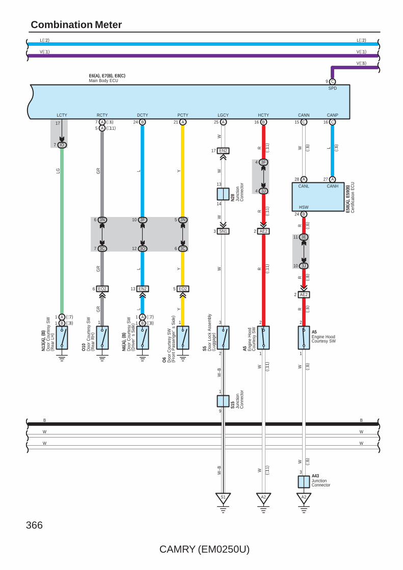
366
CAMRY (EM0250U)
Combination Meter
W
W
B
V(∗1)
L(∗2)
C9
SPD
L(∗2)
V(∗1)
W
B
W
V(∗6)
Main Body ECUE6(A), E7(B), E8(C)
W–B
L
W
3 SN1
WW
A
S5
2
EN217
3
W
LGCY
9
1
25
14
21
13
24
EN2
N6(
A), (
B)
L
EO25
1
O6
Y
EO26
1
O10
GR
3C7
3N6
L
DCTY
B
PCTY
A
RCTY
L Y
GR Y
7
3O12
3F10
3C6
GR
A
3N5
(∗6)
13
N28
S15
W
(∗11)A5
Junc
tion
Con
nect
or
Doo
r C
ourte
sy S
W( D
river
's
Sid
e)
Doo
r C
ourte
sy S
W( R
ear
RH
)
Doo
r C
ourte
sy S
W( F
ront
Pas
seng
er'
s S
ide)
Junc
tion
Con
nect
or
Doo
r Lo
ck A
ssem
bly
( Lug
gage
)
S1
LCTY
17
N13
( A) ,
( B)
IO7
LG
Doo
r C
ourte
sy S
W( R
ear
LH)
( ∗11
)( ∗
11)
( ∗11
)
B16
3F4
3J4
AE22
2
1
A2
HCTY
RR
RW
( ∗11
)
Eng
ine
Hoo
dC
ourte
sy S
W
A5
3
10 3J
R
11 3E
AE22
2
CANL
A
R
HSW
A2
28 A 27
1
B24
RW
CANH
A43
E58(
A), E
59( B
)
JunctionConnector
Cer
tific
atio
n E
CU
Engine HoodCourtesy SW
A5
C16
CANP
C15
CANN
( ∗6)
( ∗6)
(∗8)B1(∗7)A1
(∗8)B1(∗7)A1
( ∗6)
( ∗6)
( ∗6)
( ∗6)
( ∗11
)
W W ( ∗6)
W–B
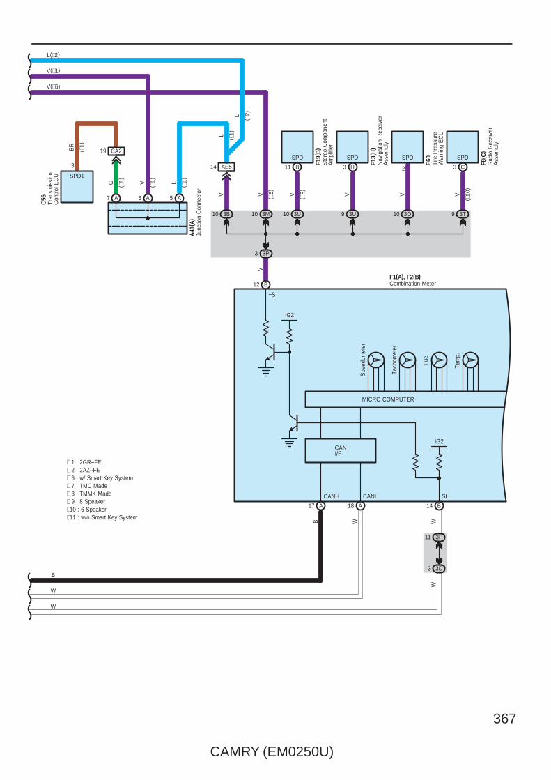
CAMRY (EM0250U)
367
IG2
IG2
17 A A18
Tem
p.
Fuel
Tach
omet
er
Spe
edom
eter
12 B
14 B
V
A7 A56 A
3B10
3P3
AE514
G V
V
L
A41(
A)
+S
SICANH CANL
∗ 7 : TMC Made∗ 6 : w/ Smart Key System
L ( ∗1)
( ∗1)
Junc
tion
Con
nect
or
∗ 8 : TMMK Made∗ 9 : 8 Speaker∗10 : 6 Speaker
3M10 10 3O 3T9
V ( ∗6) V V
( ∗10
)
( ∗9) VV
3U10 3U9
WB
3P11
3D3
WW
L ( ∗2)
( ∗1)
( ∗1)
Tran
smis
sion
Con
trol E
CU
C56
CA219
3
SPD1
BR
( ∗1)
SPD SPD SPD SPD
2
Ste
reo
Com
pone
ntA
mpl
ifier
F19(
B)
Nav
igat
ion
Rec
eive
rA
ssem
bly
F13(
H)
Tire
Pre
ssur
eW
arni
ng E
CU
E60
Rad
io R
ecei
ver
Ass
embl
y
F8( C
)
B11 H3 C3
MICRO COMPUTER
Combination MeterF1(A), F2(B)
V(∗1)
W
W
B
L(∗2)
V(∗6)
∗ 2 : 2AZ–FE∗ 1 : 2GR–FE
∗11 : w/o Smart Key System
CANI/F
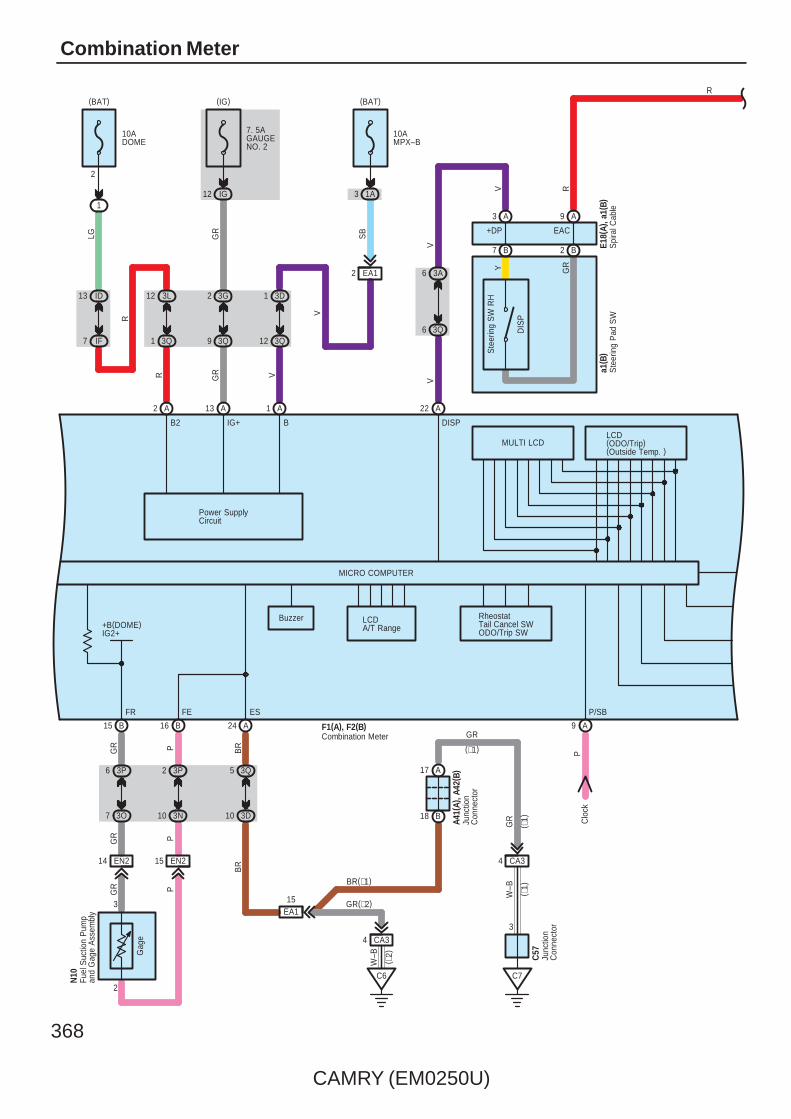
368
CAMRY (EM0250U)
Combination Meter
MICRO COMPUTER
B2 BLCD(ODO/Trip)(Outside Temp. )
LCDA/T Range+B(DOME)
IG2+
Buzzer
A9
Gag
e
A16
N10
PGR
PGR
PGR
B
15 EN2EN214
3
2
2415 B
1
V
IG+
A
1 3D
12 3Q
10AMPX–B
(BAT)
2
R
R
LG
A
12 3L
1 3Q
13 ID
7 IF
1
10ADOME
(BAT)
2
Power SupplyCircuit
13
GR
GR
A
2 3G
9 3Q
12 IG
7. 5AGAUGENO. 2
(IG)
EA12
SB
3P6
3O7
3P2
3N10
3Q5
3D10
CA34
C6
15EA1
A17
B18
CA34
C7
3
BR(∗1)
GR(∗2)
GR
W–B
W–B
GR
BR
A41(
A), A
42( B
)
C57
( ∗1)
( ∗1)
( ∗2)
(∗1)
FR FE ES P/SB
Junc
tion
Con
nect
or
Junc
tion
Con
nect
or
Fuel
Suc
tion
Pum
pan
d G
age
Ass
embl
y
BR
PC
lock
F1(A), F2(B)Combination Meter
A22
3A6
3Q6
VV
V
A3 A9
B7 B2
DIS
P
Ste
erin
g S
W R
HY GR
+DP EAC
Spi
ral C
able
E18(
A), a
1(B)
Ste
erin
g P
ad S
Wa1
( B)
R
V
1A3
MULTI LCD
DISP
R
RheostatTail Cancel SWODO/Trip SW

CAMRY (EM0250U)
369
A16
IG2
A
W–B
LG
LGLG
LG
A3
1
23 AE6
3P8
3E6
Gen
erat
or
Bra
ke( E
xcep
t US
A)
BR
AK
E( U
SA
)
B6 A23
MA
INT
RE
QD
Cha
rge
Low
Fue
l
S, 4
, 3, 2
, L
DNRP
WLVL
5
3Q3
3J11
AE23
A5
LGLG
B
CHG–
LG
LG
B/LE
DRIVE IC
SR
S
Was
her
Leve
l
Bra
ke F
luid
Leve
l War
ning
SW
L
Combination MeterF1(A), F2(B)
Washer LevelWarning SW
A52
1
2
S
E
∗ 2 : 2AZ–FE∗ 1 : 2GR–FE
R R

370
CAMRY (EM0250U)
Combination Meter
C23
DRIVE IC
IG2
LGO
1
6 CA3
Tire
Pre
ssur
eW
arni
ng E
CU
Bea
m
Tail
( Exc
ept U
SA
)H
ead
( US
A)
Fron
t Fog
Mas
ter
War
ning
DO
OR
Cru
ise
Slip
AB
S
VS
C
Driv
er'
sS
eat B
elt
A7B4
Tire
Pre
ssur
e
Mal
func
tion
Indi
cato
r La
mp
A8
CHK TIRES
EA14
OY
+B(DOME)
Oil
Pre
ssur
e
Eng
ine
Oil
Pre
ssur
e S
W
LRE
ngin
e C
ontro
lM
odul
e
F1(A), F2(B)Combination Meter
10 FE3
R R
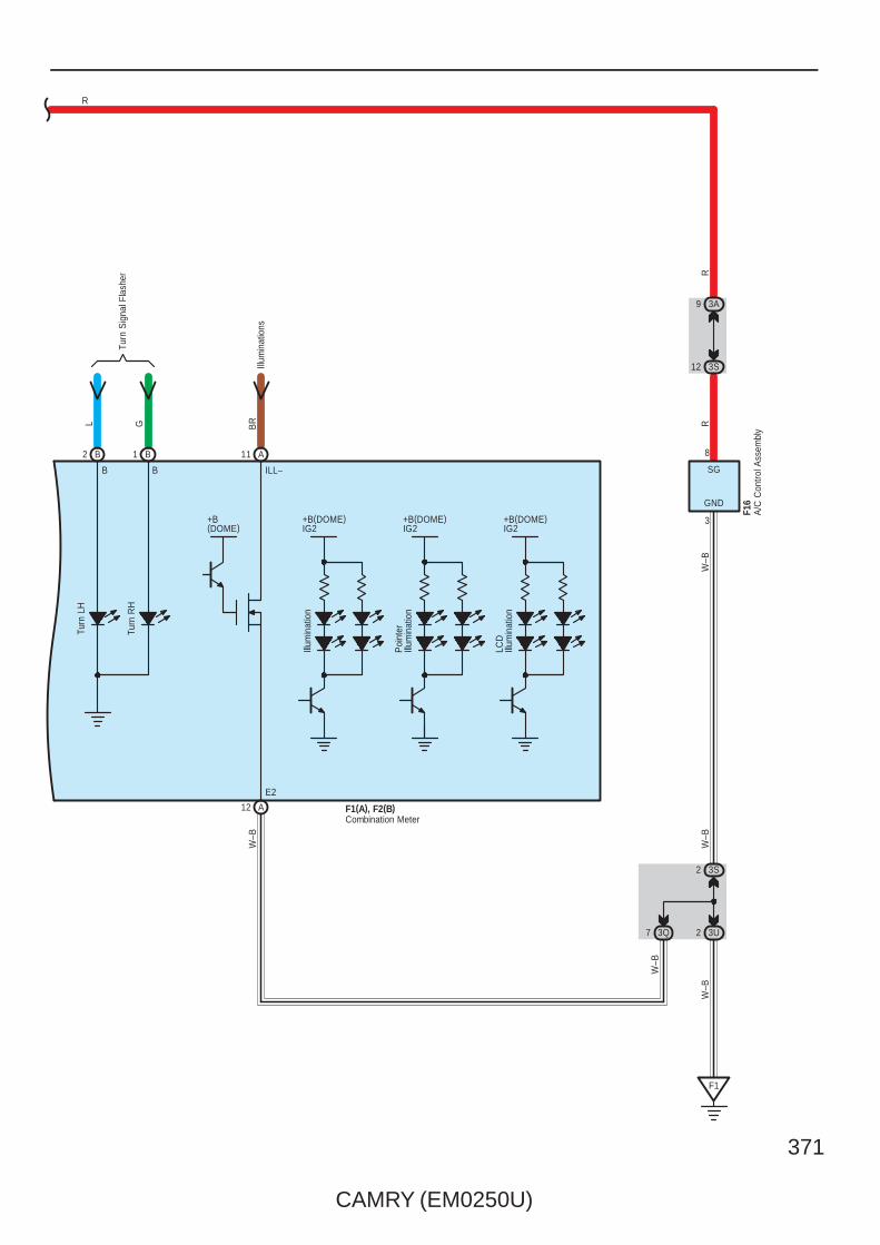
CAMRY (EM0250U)
371
+B(DOME)IG2
+B(DOME)IG2
+B(DOME)IG2
Turn
Sig
nal F
lash
er
2 1B B
Turn
LH
Turn
RH
12 A
LCD
Illum
inat
ion
Poi
nter
Illum
inat
ion
Illum
inat
ion
B
W–B
B
11 A
ILL–
Illum
inat
ions
E2
+B(DOME)
BRGL
Combination MeterF1(A), F2(B)
GND
3
W–B
W–B
SG
3S2
3U2
F1
RR
3S12
3A9
W–B
A/C
Con
trol A
ssem
bly
F16
8
3Q7
W–B
R
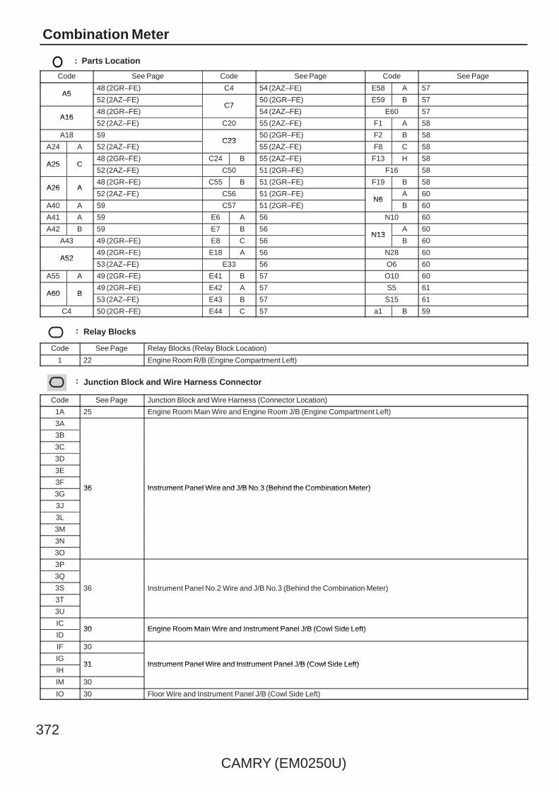
372
CAMRY (EM0250U)
Combination Meter
: Parts Location
Code See Page Code See Page Code See Page
A548 (2GR–FE) C4 54 (2AZ–FE) E58 A 57
A552 (2AZ–FE)
C750 (2GR–FE) E59 B 57
A1648 (2GR–FE)
C754 (2AZ–FE) E60 57
A1652 (2AZ–FE) C20 55 (2AZ–FE) F1 A 58
A18 59C23
50 (2GR–FE) F2 B 58
A24 A 52 (2AZ–FE)C23
55 (2AZ–FE) F8 C 58
A25 C48 (2GR–FE) C24 B 55 (2AZ–FE) F13 H 58
A25 C52 (2AZ–FE) C50 51 (2GR–FE) F16 58
A26 A48 (2GR–FE) C55 B 51 (2GR–FE) F19 B 58
A26 A52 (2AZ–FE) C56 51 (2GR–FE)
N6A 60
A40 A 59 C57 51 (2GR–FE)N6
B 60
A41 A 59 E6 A 56 N10 60
A42 B 59 E7 B 56N13
A 60
A43 49 (2GR–FE) E8 C 56N13
B 60
A5249 (2GR–FE) E18 A 56 N28 60
A5253 (2AZ–FE) E33 56 O6 60
A55 A 49 (2GR–FE) E41 B 57 O10 60
A60 B49 (2GR–FE) E42 A 57 S5 61
A60 B53 (2AZ–FE) E43 B 57 S15 61
C4 50 (2GR–FE) E44 C 57 a1 B 59
: Relay Blocks
Code See Page Relay Blocks (Relay Block Location)
1 22 Engine Room R/B (Engine Compartment Left)
: Junction Block and Wire Harness Connector
Code See Page Junction Block and Wire Harness (Connector Location)
1A 25 Engine Room Main Wire and Engine Room J/B (Engine Compartment Left)
3A
36 Instrument Panel Wire and J/B No.3 (Behind the Combination Meter)
3B
36 Instrument Panel Wire and J/B No.3 (Behind the Combination Meter)
3C
36 Instrument Panel Wire and J/B No.3 (Behind the Combination Meter)
3D
36 Instrument Panel Wire and J/B No.3 (Behind the Combination Meter)
3E
36 Instrument Panel Wire and J/B No.3 (Behind the Combination Meter)3F
36 Instrument Panel Wire and J/B No.3 (Behind the Combination Meter)3G
36 Instrument Panel Wire and J/B No.3 (Behind the Combination Meter)
3J
3L
3M
3N
3O
3P
36 Instrument Panel No.2 Wire and J/B No.3 (Behind the Combination Meter)
3Q
36 Instrument Panel No.2 Wire and J/B No.3 (Behind the Combination Meter)3S 36 Instrument Panel No.2 Wire and J/B No.3 (Behind the Combination Meter)
3T
36 Instrument Panel No.2 Wire and J/B No.3 (Behind the Combination Meter)
3U
IC30 Engine Room Main Wire and Instrument Panel J/B (Cowl Side Left)
ID30 Engine Room Main Wire and Instrument Panel J/B (Cowl Side Left)
IF 30
Instrument Panel Wire and Instrument Panel J/B (Cowl Side Left)IG
31 Instrument Panel Wire and Instrument Panel J/B (Cowl Side Left)IH
31 Instrument Panel Wire and Instrument Panel J/B (Cowl Side Left)
IM 30
IO 30 Floor Wire and Instrument Panel J/B (Cowl Side Left)

CAMRY (EM0250U)
373
: Connector Joining Wire Harness and Wire Harness
Code See Page Joining Wire Harness and Wire Harness (Connector Location)
AE2 66 Engine Room Main Wire and Instrument Panel Wire (Right Side of the Instrument Panel J/B)
AE566 Engine Room Main Wire and Instrument Panel Wire (Instrument Panel Right)
AE666 Engine Room Main Wire and Instrument Panel Wire (Instrument Panel Right)
CA164 (2GR–FE)
Engine Wire and Engine Room Main Wire (Inside of the Engine Room R/B and Engine Room J/B)
CA165 (2AZ–FE)
Engine Wire and Engine Room Main Wire (Inside of the Engine Room R/B and Engine Room J/B)CA2 64 (2GR–FE) Engine Wire and Engine Room Main Wire (Inside of the Engine Room R/B and Engine Room J/B)
CA364 (2GR–FE)
Engine Wire and Engine Room Main Wire (Inside of the Engine Room R/B and Engine Room J/B)
CA365 (2AZ–FE)
EA1 66 Instrument Panel Wire and Engine Room Main Wire (Left Kick Panel)
EN2 66 Instrument Panel Wire and Floor Wire (Left Kick Panel)
EO2 66 Instrument Panel Wire and Floor No.2 Wire (Right Kick Panel)
FE3 66 Instrument Panel No.2 Wire and Instrument Panel Wire (Instrument Panel Center)
SN1 67 Luggage Room Wire and Floor Wire (Luggage Room Left)
: Ground Points
Code See Page Ground Points Location
A264 (2GR–FE)
Front Left FenderA265 (2AZ–FE)
Front Left Fender
A3 66 Left Cowl Side Panel
A564 (2GR–FE)
Front Right FenderA565 (2AZ–FE)
Front Right Fender
C4 65 (2AZ–FE) Cylinder Block
C5 64 (2GR–FE) Right Side of the Cylinder Block
C6 65 (2AZ–FE) Cylinder Block
C7 64 (2GR–FE) Left Side of the Cylinder Block
F1 66 Instrument Panel Left
S1 67 Lower Back Panel Center

374
CAMRY (EM0250U)
Cooling Fan for 2GR–FE
50AFAN MAIN
10AECU IGNO. 1
1 IC6
5 2
3 1
1 1
1 1
(BAT) (IG)
2 1
3
S1 E1
+B1
A54
A56(A), A57(B)
A1
W–BG
G
B
W–B
W–B
W–B
LGW
W LG
FAN MAINRelay
B
MM
M–(S)
M+(S)
M–(M)
M+(M)
MainFanMotor
SubFanMotor
1 A
1 B
Coo
ling
Fan
EC
U
Short Connector
A49 A41
CANL CANH
W B
C4
Eng
ine
Coo
lant
Tem
p.
Sen
sor
2
ETHW
B
79
1
78
P
B
THW
B
Cra
nksh
aft
Pos
ition
Sen
sor
C50
110
( Shi
elde
d)
RG
NE+
B
NE–
B
1
2
111
BR
A8
V
SPD
A55(A), C55(B)Engine Control Module
C5
A43
RFC
B
W
V
G

CAMRY (EM0250U)
375
V
7 A
10 B
RVL
AE620 AE618
A27
1 3 2
– + PR
S5–3 PRE
A13
SG–2
E38(A)
A A10 9
∗ 1 : Automatic A/C
F16
GR
LTX+
4
A
GND
3
W–B
W–B
LIN1
3 3M
4 3S
9
ADI1
8
SG
3S2
3U2
F1
B R
B R
a1(B)
TEMP–
TEMP+
OFF
AUTO
37
E18(
A), a
1(B)
Ste
erin
g S
W R
H
10AA/CNO. 2
IF16
(IG)
3E2
3M4
3D11
3M113M8
V
VBRL
BR V
3K9
3S3
3A3
3S12
3A9
( ∗1)
( ∗1)
( ∗1)
( ∗1)
W–B
A/C Pressure Sensor
Steering Pad SW
A/C Amplifier
A/C Control AssemblyS
pira
l Cab
le
P GR
B3 B2
AC1 EAC
A10 A9
Junc
tion
Con
nect
or
A58(
A), E
40( B
)
3L1
3S1
V
IG+
5
VW
B
W
B
V
L
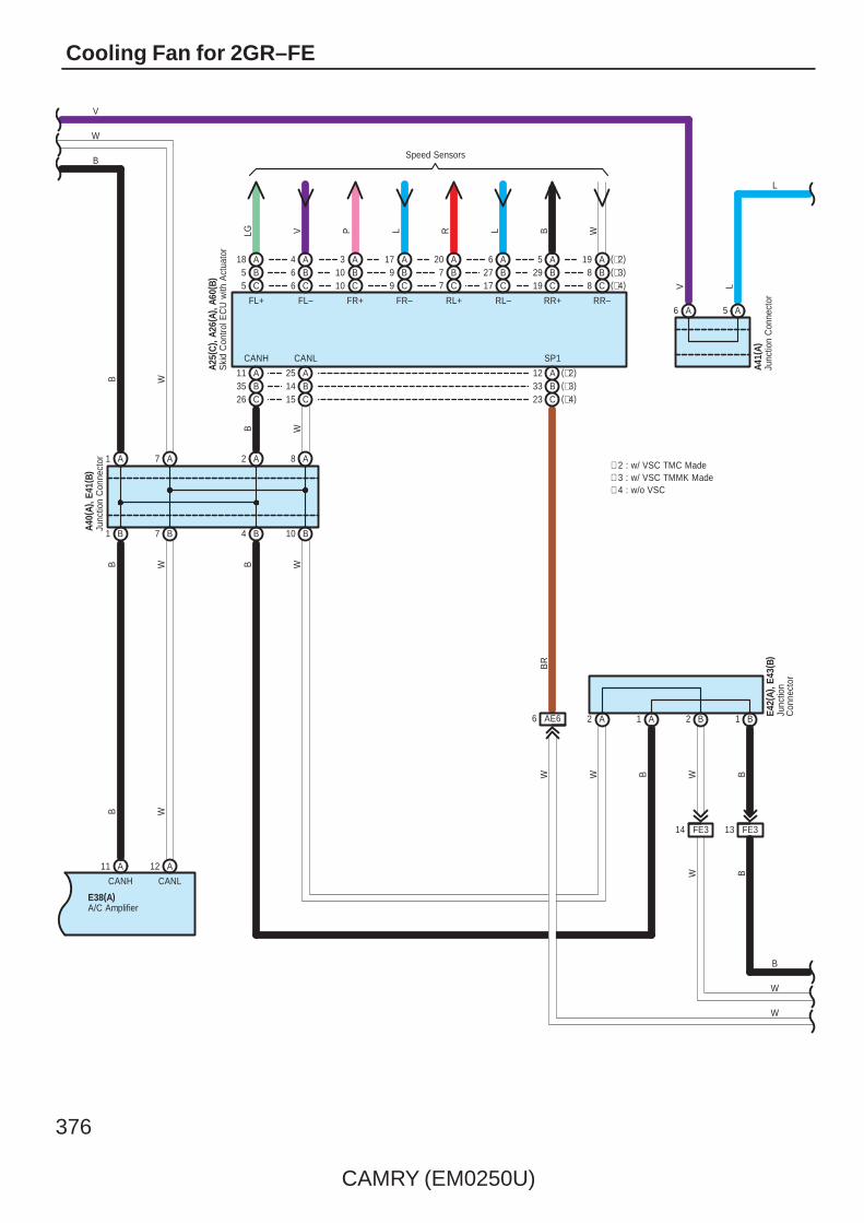
376
CAMRY (EM0250U)
Cooling Fan for 2GR–FE
8 C (∗4)(∗3)B8(∗2)A19
C19B29A5
C17B27A6
C7B7A20
C9B9A17
C10B10A3
C6B6A4
C5B5A18
Speed Sensors
LG V P L R L B W
AB
11 (∗2)
A1 A7
26 C35
B4 B10
A2 A8
A25B14C15
A12(∗3)B33(∗4)C23
FL+ FL– FR+ FR– RL+ RL– RR+ RR–
CANH CANL SP1
AE66
BR
W
2 A 1 A 2 B 1 B
BW
BWBW
WB
B W
B W
E42(
A), E
43( B
)
Ski
d C
ontro
l EC
U w
ith A
ctua
tor
A25(
C) ,
A26(
A), A
60( B
)
Junc
tion
Con
nect
or
Junc
tion
Con
nect
orA4
0(A)
, E41
( B)
A56 A
V L
A41(
A)Ju
nctio
n C
onne
ctor
V
CANLCANH
11 12A A
B1 B7
WBB W
E38(A)A/C Amplifier
L
B
W
W
W
B
∗ 2 : w/ VSC TMC Made∗ 3 : w/ VSC TMMK Made∗ 4 : w/o VSC
14 FE3 13 FE3
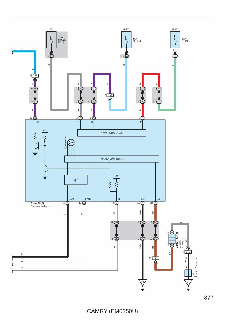
CAMRY (EM0250U)
377
IG2
17 A A18 14 B
SICANH CANL
F1(A), F2(B)Combination Meter
MICRO COMPUTER
WB
3P11
3D3
WW
IG2
12 B
V
3P3
AE514
V
+S
L
3B10
BR
BR
15 EA1
Junc
tion
Con
nect
or
Junc
tion
Con
nect
or
Spe
edom
eter
W–B
Power Supply Circuit
ES
C57
A41(
A), A
42( B
)
BR
GR
W–B
GR
3
C7
4 CA3
18 B
17 A
10 3D
5 3Q
24 A
R
2
VGR
GR
2 A1 A13 A
9 3Q
2 3G
R
1 3Q
12 3L
13 ID
E2
B2IG+ B
10AMPX–B
(BAT)
7. 5AGAUGENO. 2
IG12
(IG)
F1
W–B
VGR
SB
EA1
3D1
3Q12
V
3Q7
3U2
A12
10ADOME
1
2
(BAT)
R
LG
IF7
L
W
B
W
1A3
CANI/F

378
CAMRY (EM0250U)
Cooling Fan for 2GR–FE
System OperationWhen the power SW is pushed to IG ON position (Power SW type), or when the ignition SW is turned to ON (Ignition SWtype), the current from the ECU IG NO.1 fuse is sent to the coil side and the FAN MAIN relay is turned to ON. Then thecurrent flows to TERMINAL 3 of the cooling fan ECU. At the same time, the conditions of the A/C SW, A/C pressure sensor,engine coolant temp. sensor and engine rotation are sent to the TERMINAL 2 as signals from engine control module. As aresult of that, the cooling fan ECU continuously controls the rotation of the fan motor and keeps a balance between thecooling efficiency and silentness with the optimal fan rotation.
: Parts Location
Code See Page Code See Page Code See Page
A25 C 48 (2GR–FE) A57 B 59 E40 B 57
A26 A 48 (2GR–FE) A58 A 59 E41 B 57
A27 48 (2GR–FE) A60 B 49 (2GR–FE) E42 A 57
A40 A 59 C4 50 (2GR–FE) E43 B 57
A41 A 59 C50 51 (2GR–FE) F1 A 58
A42 B 59 C55 B 51 (2GR–FE) F2 B 58
A54 49 (2GR–FE) C57 51 (2GR–FE) F16 58
A55 A 49 (2GR–FE) E18 A 56 a1 B 59
A56 A 59 E38 A 57
: Relay Blocks
Code See Page Relay Blocks (Relay Block Location)
1 22 Engine Room R/B (Engine Compartment Left)
: Junction Block and Wire Harness Connector
Code See Page Junction Block and Wire Harness (Connector Location)
1A 25 Engine Room Main Wire and Engine Room J/B (Engine Compartment Left)
3A
36 Instrument Panel Wire and J/B No.3 (Behind the Combination Meter)
3B
36 Instrument Panel Wire and J/B No.3 (Behind the Combination Meter)
3D
36 Instrument Panel Wire and J/B No.3 (Behind the Combination Meter)3E
36 Instrument Panel Wire and J/B No.3 (Behind the Combination Meter)3G
36 Instrument Panel Wire and J/B No.3 (Behind the Combination Meter)
3K
3L
3M
3P
36 Instrument Panel No.2 Wire and J/B No.3 (Behind the Combination Meter)3Q
36 Instrument Panel No.2 Wire and J/B No.3 (Behind the Combination Meter)3S
36 Instrument Panel No.2 Wire and J/B No.3 (Behind the Combination Meter)
3U
IC30 Engine Room Main Wire and Instrument Panel J/B (Cowl Side Left)
ID30 Engine Room Main Wire and Instrument Panel J/B (Cowl Side Left)
IF 30Instrument Panel Wire and Instrument Panel J/B (Cowl Side Left)
IG 31Instrument Panel Wire and Instrument Panel J/B (Cowl Side Left)
: Connector Joining Wire Harness and Wire Harness
Code See Page Joining Wire Harness and Wire Harness (Connector Location)
AE566 Engine Room Main Wire and Instrument Panel Wire (Instrument Panel Right)
AE666 Engine Room Main Wire and Instrument Panel Wire (Instrument Panel Right)
CA3 64 (2GR–FE) Engine Wire and Engine Room Main Wire (Inside of the Engine Room R/B and Engine Room J/B)
EA1 66 Instrument Panel Wire and Engine Room Main Wire (Left Kick Panel)
FE3 66 Instrument Panel No.2 Wire and Instrument Panel Wire (Instrument Panel Center)
System Outline

CAMRY (EM0250U)
379
: Ground Points
Code See Page Ground Points Location
A1 64 (2GR–FE) Front Left Fender
C5 64 (2GR–FE) Right Side of the Cylinder Block
C7 64 (2GR–FE) Left Side of the Cylinder Block
F1 66 Instrument Panel Left

380
CAMRY (EM0250U)
Radiator Fan and Condenser Fan for 2AZ–FE
40ARDI FAN
10AECU IGNO. 1
B
G
1 IC6
40ACDS FAN
1
5 2
3 1
1 1
1 1
4
51
32
1 1
1 1
(BAT) (IG) (BAT)
W
L
LG
A1
FAN
NO
. 3R
elay
L
W
L
W–B
W–B
FAN
NO
. 2R
elay
FAN
NO
. 1R
elay
LG
W R
W–B
1
G
LGW
W LG
L
3 2
5 1
1 1
1 1
M
1
2
A7
W–B
Rad
iato
rFa
n M
otor
W BL
B
W
L
Cra
nksh
aft
Pos
ition
Sen
sor
B–W
W–B
1 CA3
2 CA3
C4
C20
( Shi
elde
d)NE+ NE–
B122 B121G R
2
L
1
C4
Eng
ine
Coo
lant
Tem
p.
Sen
sor
1
2
B
ETHWTHW
96 BB97
P
A41A49A8
CANHCANLSPD
FANL FANH
A21 A22
R W
M
2
1
A/C
Con
dens
erFa
n M
otor
A6
W
Eng
ine
Con
trol M
odul
eA2
4(A)
, C24
( B)
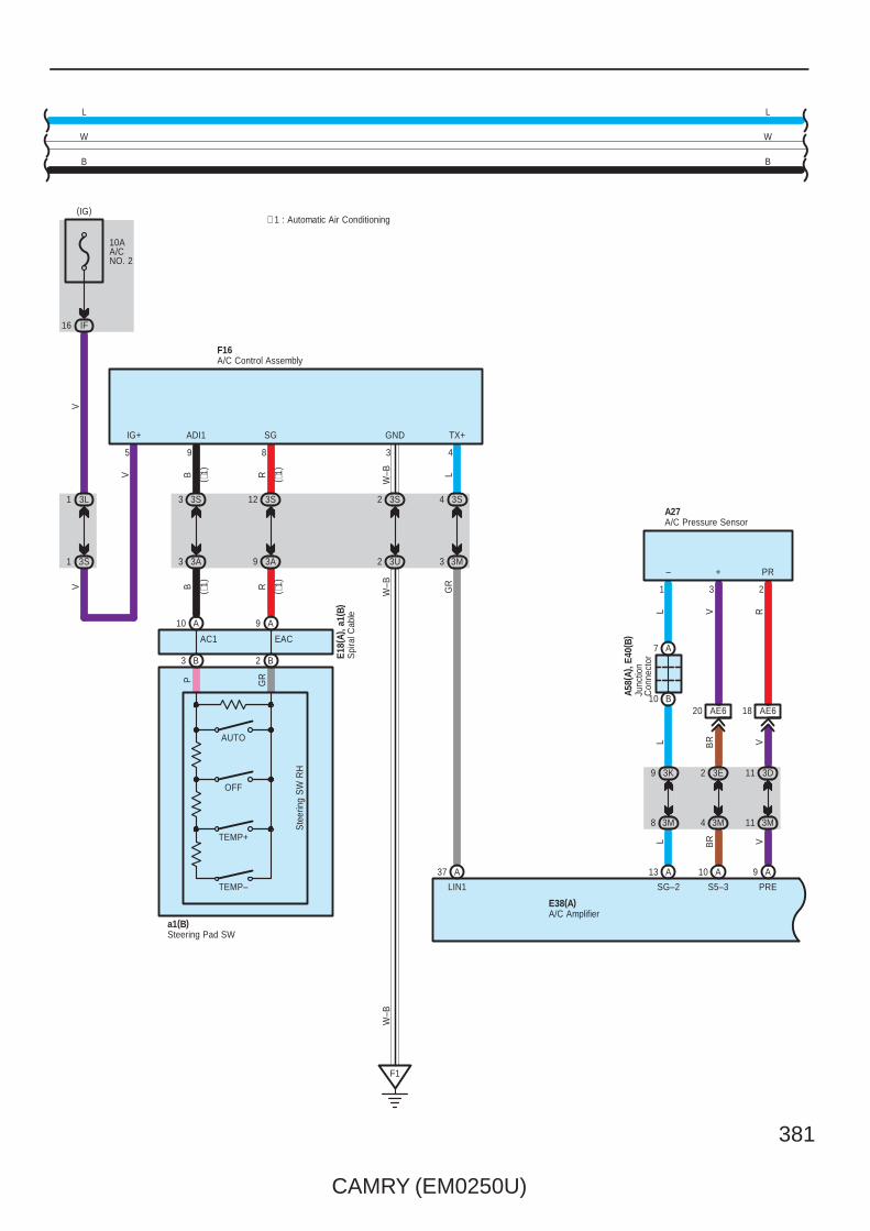
CAMRY (EM0250U)
381
B
WW
B
LV
L
5
A58(
A), E
40( B
)Ju
nctio
nC
onne
ctor
7 A
10 B
RVL
AE620 AE618
A27
1 3 2
– + PR
S5–3 PRE
A13
SG–2
E38(A)
A A10 9
∗ 1 : Automatic Air Conditioning
F16
GR
LTX+
4
A
GND
3
W–B
W–B
LIN1
3 3M
4 3S
9
ADI1
8
SG
3S2
3U2
F1
B R
B R
a1(B)
TEMP–
TEMP+
OFF
AUTO
37
E18(
A), a
1(B)
Ste
erin
g S
W R
H
IG+
10AA/CNO. 2
IF16
(IG)
V
3E2
3M4
3D11
3M113M8
V
VBRL
BR V
1 3S
1 3L
3K9
3S3
3A3
3S12
3A9
( ∗1)
( ∗1)
( ∗1)
( ∗1)
W–B
A/C Pressure Sensor
Steering Pad SW
A/C Amplifier
A/C Control AssemblyS
pira
l Cab
le
P GR
B3 B2
AC1 EAC
A10 A9
L
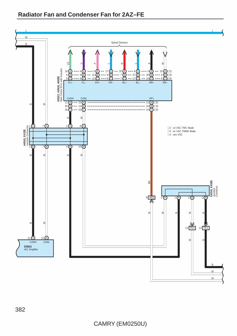
382
CAMRY (EM0250U)
Radiator Fan and Condenser Fan for 2AZ–FE
8 C (∗4)(∗3)B8(∗2)A19
C19B29A5
C17B27A6
C7B7A20
C9B9A17
C10B10A3
C6B6A4
C5B5A18
Speed Sensors
LG V P L R L B W
AB
11 (∗2)
A1 A7
26 C35
B4 B10
A2 A8
A25B14C15
A12(∗3)B33(∗4)C23
FL+ FL– FR+ FR– RL+ RL– RR+ RR–
CANH CANL SP1
AE66
BR
W
2 A 1 A 2 B 1 B
W
W
B
BW
BWBW
W
B
WB
B W
B W
E42(
A), E
43( B
)
Ski
d C
ontro
l EC
U w
ith A
ctua
tor
A25(
C) ,
A26(
A), A
60( B
)
∗ 4 : w/o VSC∗ 3 : w/ VSC TMMK Made∗ 2 : w/ VSC TMC Made
Junc
tion
Con
nect
or
Junc
tion
Con
nect
orA4
0(A)
, E41
( B)
LL
E38(A)A/C Amplifier
W
B W
7 B1 B
CANLCANH
B
11 12A A
FE314 FE313

CAMRY (EM0250U)
383
17 A A18 14 B
SICANH CANL
F1(A), F2(B)Combination Meter
WB
3P11
3D3
WW
L
W
W
12 B
V
B
3P3
AE514
VL
3B10 7 IF
LG
R
(BAT)
2
1
10ADOME
12 A
2 3U
7 3Q
V
12 3Q
1 3D
EA1
SB
GR V
W–B
F1
(IG)
12 IG
7. 5AGAUGENO. 2
(BAT)
1A
10AMPX–B
E2
ID13
3L12
3Q1
R
3G2
3Q9
A13 A1 A2
GR
GR V
2
R
A24
3Q5
3D10
BR
ES
W–B EA115
BR
W–B
GR
C6
CA34
GR
3
CANI/F
IG2
MICRO COMPUTER
IG2
+S BIG+ B2
Power Supply Circuit
Spe
edom
eter

384
CAMRY (EM0250U)
Radiator Fan and Condenser Fan for 2AZ–FE
: Parts Location
Code See Page Code See Page Code See Page
A6 52 (2AZ–FE) A60 B 53 (2AZ–FE) E42 A 57
A7 52 (2AZ–FE) C4 54 (2AZ–FE) E43 B 57
A24 A 52 (2AZ–FE) C20 55 (2AZ–FE) F1 A 58
A25 C 52 (2AZ–FE) C24 B 55 (2AZ–FE) F2 B 58
A26 A 52 (2AZ–FE) E18 A 56 F16 58
A27 52 (2AZ–FE) E38 A 57 a1 B 59
A40 A 59 E40 B 57
A58 A 59 E41 B 57
: Relay Blocks
Code See Page Relay Blocks (Relay Block Location)
1 22 Engine Room R/B (Engine Compartment Left)
: Junction Block and Wire Harness Connector
Code See Page Junction Block and Wire Harness (Connector Location)
1A 25 Engine Room Main Wire and Engine Room J/B (Engine Compartment Left)
3A
36 Instrument Panel Wire and J/B No.3 (Behind the Combination Meter)
3B
36 Instrument Panel Wire and J/B No.3 (Behind the Combination Meter)
3D
36 Instrument Panel Wire and J/B No.3 (Behind the Combination Meter)3E
36 Instrument Panel Wire and J/B No.3 (Behind the Combination Meter)3G
36 Instrument Panel Wire and J/B No.3 (Behind the Combination Meter)
3K
3L
3M
3P
36 Instrument Panel No.2 Wire and J/B No.3 (Behind the Combination Meter)3Q
36 Instrument Panel No.2 Wire and J/B No.3 (Behind the Combination Meter)3S
36 Instrument Panel No.2 Wire and J/B No.3 (Behind the Combination Meter)
3U
IC30 Engine Room Main Wire and Instrument Panel J/B (Cowl Side Left)
ID30 Engine Room Main Wire and Instrument Panel J/B (Cowl Side Left)
IF 30Instrument Panel Wire and Instrument Panel J/B (Cowl Side Left)
IG 31Instrument Panel Wire and Instrument Panel J/B (Cowl Side Left)
: Connector Joining Wire Harness and Wire Harness
Code See Page Joining Wire Harness and Wire Harness (Connector Location)
AE566 Engine Room Main Wire and Instrument Panel Wire (Instrument Panel Right)
AE666 Engine Room Main Wire and Instrument Panel Wire (Instrument Panel Right)
CA3 65 (2AZ–FE) Engine Wire and Engine Room Main Wire (Inside of the Engine Room R/B and Engine Room J/B)
EA1 66 Instrument Panel Wire and Engine Room Main Wire (Left Kick Panel)
FE3 66 Instrument Panel No.2 Wire and Instrument Panel Wire (Instrument Panel Center)
: Ground Points
Code See Page Ground Points Location
A1 65 (2AZ–FE) Front Left Fender
C465 (2AZ–FE) Cylinder Block
C665 (2AZ–FE) Cylinder Block
F1 66 Instrument Panel Left

CAMRY (EM0250U)
385
Memo
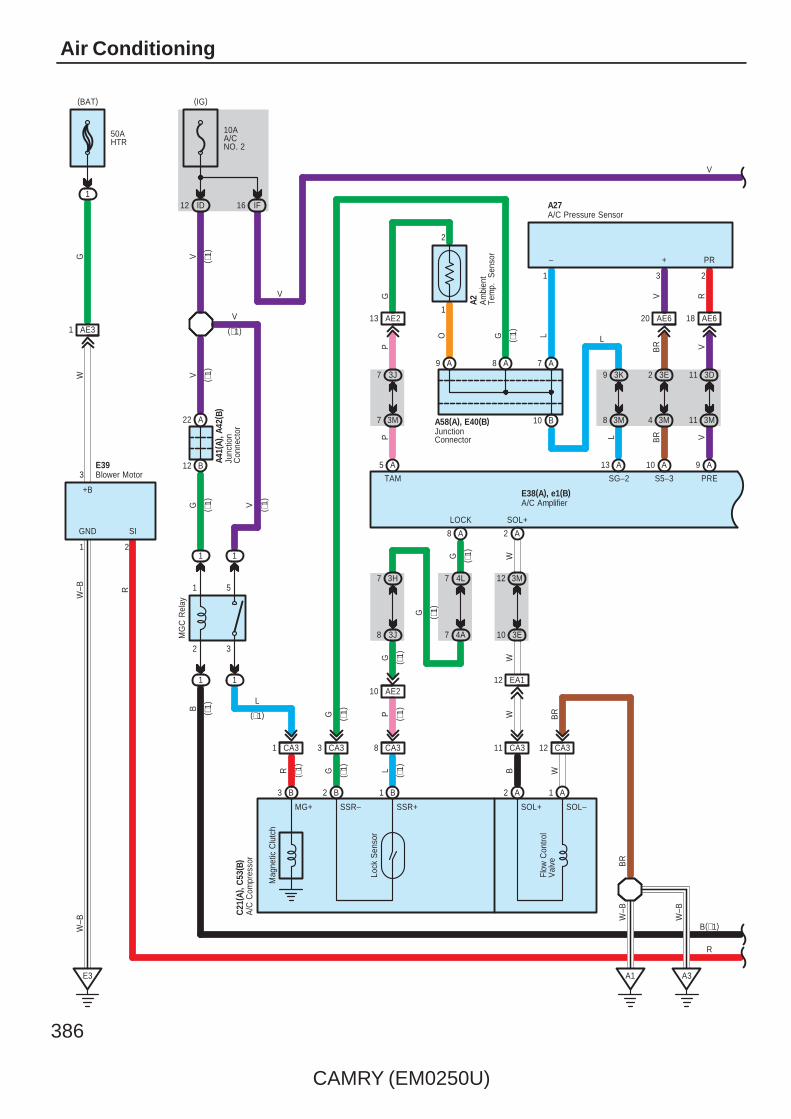
386
CAMRY (EM0250U)
Air Conditioning
22 A
B12
7 A
50AHTR
1
AE31
Lock
Sen
sor
1
MG
C R
elay
1
5
1 1
2 3
1
CA383 CA3CA31 11 CA3
C21
( A) ,
C53
( B)
9 A
10 B
Mag
netic
Clu
tch
RV
L
AE620 AE618
A27
1 3 2
1 2
3
LOCK SOL+
– + PR
GND SI
+B
A
S5–3 PRE
BR
R LG B
A13
SG–2
( ∗1)
W–B R
WG
A1E3
W–B
(BAT)
A
A A10 9
28
12 CA3
W
MG+ SSR+SSR– SOL+ SOL–
Flow
Con
trol
Val
ve
B3 B1B2 A2 A1
3M12
3E10
3H7
3J8
4L7
4A7
EA112AE210
10AA/CNO. 2
ID12
(IG)
IF16
3E2
3M4
3D11
3M113M8
L
A8
G
AE213
TAM
A5
3J7
3M7
A3
V ( ∗1)
A41(
A), A
42( B
)
G ( ∗1) V ( ∗1)
B
WW
( ∗1)P( ∗1)G
( ∗1)G
( ∗1)G
( ∗1)G
BR
( ∗1)
( ∗1)
( ∗1)
G ( ∗1)
W
W–B
W–B
V
VBRL
BR V
O
PP
3K9
L
(∗1)
A/C Pressure Sensor
Junc
tion
Con
nect
orA
/C C
ompr
esso
r
1
2
Am
bien
tTe
mp.
S
enso
r
A2
JunctionConnector
A58(A), E40(B)
Blower MotorE39
V
B(∗1)
R
E38(A), e1(B)A/C Amplifier
V ( ∗1)
V
(∗1)
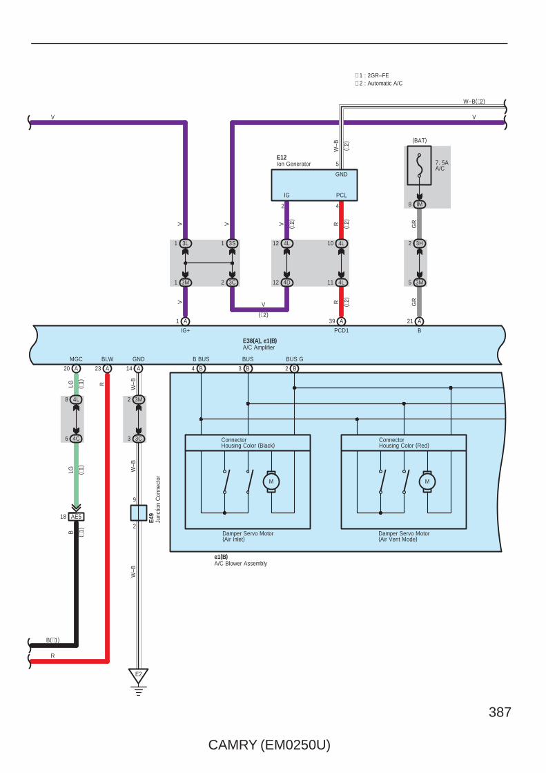
CAMRY (EM0250U)
387
( ∗1)
18 AE5
7. 5AA/C
IM8
MGC BLW
( ∗1)
BIG+
B
V
LG R
GND
E38(A), e1(B)
(BAT)
Damper Servo Motor(Air Inlet)
B B B
AA
A A 14 4
LG
A
B BUS BUS BUS G
M
W–B(∗2)
211
2320 3 2
M
Damper Servo Motor(Air Vent Mode)
V
ConnectorHousing Color (Black)
ConnectorHousing Color (Red)
(∗2)
4L8
4C6
3C2
3L1 3S1
3M1
4L12
4D12
3M2
3C3
2
9
E2
( ∗1)
W–B
W–B
W–B
E49
VVV
W–B
2
IG
4
PCL
E12
( ∗2)
5
GND
PCD1
A39
4L10
4L11
R ( ∗2)
R ( ∗2)
( ∗2)
V
3H2
3M5
GR
GR
∗ 2 : Automatic A/C∗ 1 : 2GR–FE
Ion Generator
A/C Amplifier
Junc
tion
Con
nect
or
A/C Blower Assemblye1(B)
V
B(∗1)
R
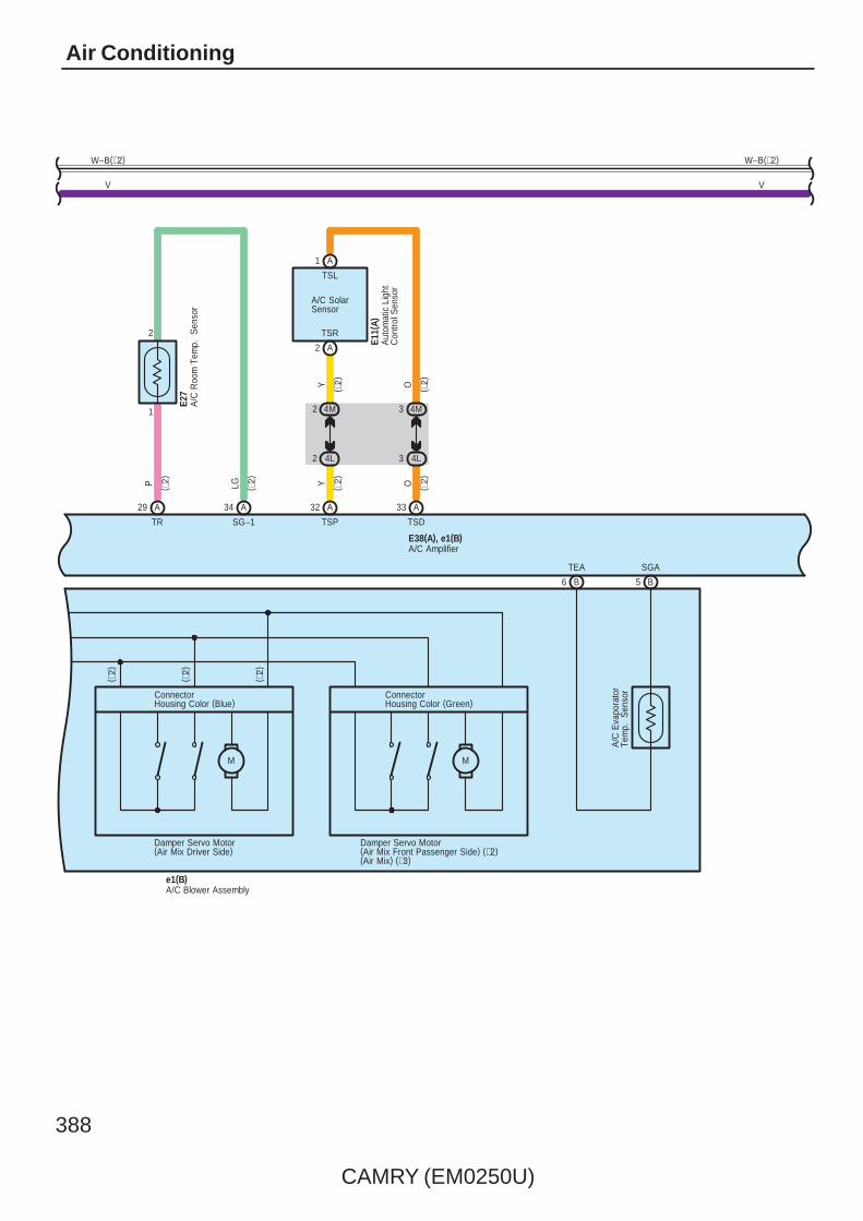
388
CAMRY (EM0250U)
Air Conditioning
M
SGA
E38(A), e1(B)
BB
M
Damper Servo Motor(Air Mix Driver Side)
Damper Servo Motor(Air Mix Front Passenger Side) (∗2)(Air Mix) (∗3)
W–B(∗2)
TEA
6 5
ConnectorHousing Color (Blue)
ConnectorHousing Color (Green)
A/C Blower Assembly
A/C
Eva
pora
tor
Tem
p.
Sen
sor
1
2
4M2
4L2
4M3
4L3
V
TSD
33 A
TSP
32 A
SG–1
34 A
TR
29 A
YLGP O
Y O
E11(
A)
( ∗2)
( ∗2)
( ∗2)
( ∗2)
( ∗2)
( ∗2)
TSR
TSL
E27
Aut
omat
ic L
ight
Con
trol S
enso
r
A/C
Roo
m T
emp.
S
enso
r
A/C Amplifier
e1(B)
( ∗2)
( ∗2)
( ∗2)
A/C SolarSensor
W–B(∗2)
V
A2
A1

CAMRY (EM0250U)
389
2
∗ 2 : Automatic A/C
F16
GR
L
TX+
4
A
GND
3
W–B
W–B
LIN1
3 3M
4 3S
9
ADI1
8
SG
IG+
5
3S2
3U2
F1
B R
B R
a1(B)
TEMP–
TEMP+
OFF
AUTO
37
E18(
A), a
1(B)
Ste
erin
g S
W R
H
E2
1
4L1
4D3
V
W–B
( ∗2)
W–B
( ∗2)
E49
W–B
( ∗2)
3S3
3A3
3S12
3A9
( ∗2)
( ∗2)
( ∗2)
( ∗2)
∗ 3 : Manual A/C
W–B
W–B
( ∗2)
Steering Pad SW
Junc
tion
Con
nect
or
A/C Control Assembly
Spi
ral C
able
P GR
B3 B2
AC1 EAC
A10 A9
A11A12
CANHCANL
BW
W
B
W–B(∗2)
V
E38(A), e1(B)A/C Amplifier

390
CAMRY (EM0250U)
Air Conditioning
Cra
nksh
aft
Pos
ition
Sen
sor
B–W
W–B
1 CA3
2 CA3
C4
C20
( Shi
elde
d)
NE+ NE–
B122 B121
G R
2
L
1
( ∗4)
( ∗4)
( ∗4)
( ∗4)
( ∗4)
C4
Eng
ine
Coo
lant
Tem
p.
Sen
sor
1
2
B
ETHWTHW
96 BB97
P( ∗4)
( ∗4)
A41A49A8
BWL ( ∗4)
( ∗4)
( ∗4)
CANHCANLSPD
B
W
Accelerator Position Sensor
A A A A A A565559576058
VPA2VPAEPAVCPAEPA2VCP2
L O B Y G R
VCP2
1
EPA2
2
VCPA
4
EPA
5
VPA
6
VPA2
3
A17
Engine Control ModuleA24(A), C24(B)
W
B
B
W
L
(∗4)
(∗4)
(∗4)
( ∗4)
( ∗4)
( ∗4)
( ∗4)
( ∗4)
( ∗4)
( Shi
elde
d)
( ∗4)

CAMRY (EM0250U)
391
A49 A41
CANL CANH
W B
A1 A7
B W
C4
Eng
ine
Coo
lant
Tem
p.
Sen
sor
2
ETHW
B
79
1
78
P
B
THW
B
( ∗1)
( ∗1)
Cra
nksh
aft
Pos
ition
Sen
sor
C5
C50
110
( Shi
elde
d)
RG
NE+
B
NE–
B
1
2
111
BR
( ∗1)
( ∗1)
( ∗1)
A8
V(∗1)
V ( ∗1)
( ∗1)
( ∗1)
( ∗1) B W ( ∗4)
( ∗4)
( ∗1)
SPD
Junc
tion
Con
nect
orA4
0(A)
, E41
( B)
B1 B7
B W
Accelerator Position Sensor
A A A A A A595557605658
EPAVPAVCPAEPA2VPA2VCP2
L R O B G Y
VCP2
1
VPA2
3
EPA2
2
VCPA
4
VPA
6
EPA
5
A17
Engine Control ModuleA55(A), C55(B)
B
W
(∗4)
(∗4)
(∗4)
L
W
B
L(∗4)
( ∗1)
( ∗1)
( ∗1)
( ∗1)
( ∗1)
( ∗1)
∗ 4 : 2AZ–FE∗ 1 : 2GR–FE
( ∗1)

392
CAMRY (EM0250U)
Air Conditioning
( ∗1)
A56 A
V L
A41(
A)( ∗
1)
Junc
tion
Con
nect
or
L(∗4)
8 C (∗7)(∗6)B8(∗5)A19
C19B29A5
C17B27A6
C7B7A20
C9B9A17
C10B10A3
C6B6A4
C5B5A18
Speed Sensors
LG V P L R L B W
AB
11 (∗5)
26 C35
B4 B10
A2 A8
A25B14C15
A12(∗6)B33(∗7)C23
FL+ FL– FR+ FR– RL+ RL– RR+ RR–
CANH CANL SP1
AE66
BR
W
2 A 1 A 2 B 1 B
W
BW
BWBW
B
W
WBB W
E42(
A), E
43( B
)
Ski
d C
ontro
l EC
U w
ith A
ctua
tor
A25(
C) ,
A26(
A), A
60( B
)
Junc
tion
Con
nect
or
V(∗1)
Junc
tion
Con
nect
orA4
0(A)
, E41
( B)
∗ 1 : 2GR–FE∗ 4 : 2AZ–FE
L(∗4)
L
(∗1)∗ 5 : w/ VSC TMC Made∗ 6 : w/ VSC TMMK Made∗ 7 : w/o VSC
13 FE314 FE3

CAMRY (EM0250U)
393
B2 B
17 A A18
1
V
IG+
A
1 3D
12 3Q
10AMPX–B
(BAT)
2
R
R
LG
A
12 3L
1 3Q
13 ID
7 IF
1
10ADOME
(BAT)
2
13
GR
GR
A
2 3G
9 3Q
12 IG
7. 5AGAUGENO. 2
(IG)
12 B
14 B
V
3P3
AE514
V
EA12
V
V
+S
SB
SICANH CANL
L ( ∗1)
F1(A), F2(B)Combination Meter
3B10
WB
3P11
3D3
WW
W
W
B
L(∗4)
L ( ∗4)
A24
3Q5
3D10
CA34
C6
15EA1
A17
B18
CA34
C7
3
BR(∗1)
GR(∗4)
GR
W–B
W–B
GR
BR
A41(
A), A
42( B
)
C57
( ∗1)
( ∗1)
( ∗4)
(∗1)
ES
Junc
tion
Con
nect
or
Junc
tion
Con
nect
or
BR
12 A
3Q7
3U2
F1
W–B
W–B
L
(∗1)
E2
1A3
CANI/F
IG2
MICRO COMPUTER
IG2Power Supply Circuit
Spe
edom
eter

394
CAMRY (EM0250U)
Air Conditioning
: Parts Location
Code See Page Code See Page Code See Page
A248 (2GR–FE)
A60 B49 (2GR–FE) E27 56
A252 (2AZ–FE)
A60 B53 (2AZ–FE) E38 A 57
A17 59C4
50 (2GR–FE) E39 57
A24 A 52 (2AZ–FE)C4
54 (2AZ–FE) E40 B 57
A25 C48 (2GR–FE) C20 55 (2AZ–FE) E41 B 57
A25 C52 (2AZ–FE)
C21 A50 (2GR–FE) E42 A 57
A26 A48 (2GR–FE)
C21 A55 (2AZ–FE) E43 B 57
A26 A52 (2AZ–FE) C24 B 55 (2AZ–FE) E49 57
A2748 (2GR–FE) C50 51 (2GR–FE) F1 A 58
A2752 (2AZ–FE) C53 B 51 (2GR–FE) F2 B 58
A40 A 59 C55 B 51 (2GR–FE) F16 58
A41 A 59 C57 51 (2GR–FE) a1 B 59
A42 B 59 E11 A 56 e1 B 59
A55 A 49 (2GR–FE) E12 56
A58 A 59 E18 A 56
: Relay Blocks
Code See Page Relay Blocks (Relay Block Location)
1 22 Engine Room R/B (Engine Compartment Left)
: Junction Block and Wire Harness Connector
Code See Page Junction Block and Wire Harness (Connector Location)
1A 25 Engine Room Main Wire and Engine Room J/B (Engine Compartment Left)
3A
36 Instrument Panel Wire and J/B No.3 (Behind the Combination Meter)
3B
36 Instrument Panel Wire and J/B No.3 (Behind the Combination Meter)
3C
36 Instrument Panel Wire and J/B No.3 (Behind the Combination Meter)
3D
36 Instrument Panel Wire and J/B No.3 (Behind the Combination Meter)
3E
36 Instrument Panel Wire and J/B No.3 (Behind the Combination Meter)3G 36 Instrument Panel Wire and J/B No.3 (Behind the Combination Meter)
3H
36 Instrument Panel Wire and J/B No.3 (Behind the Combination Meter)
3J
3K
3L
3M
3P
36 Instrument Panel No.2 Wire and J/B No.3 (Behind the Combination Meter)3Q
36 Instrument Panel No.2 Wire and J/B No.3 (Behind the Combination Meter)3S
36 Instrument Panel No.2 Wire and J/B No.3 (Behind the Combination Meter)
3U
4A
42 Instrument Panel Wire and J/B No.4 (Instrument Panel Brace Center)
4C
42 Instrument Panel Wire and J/B No.4 (Instrument Panel Brace Center)4D 42 Instrument Panel Wire and J/B No.4 (Instrument Panel Brace Center)
4L
42 Instrument Panel Wire and J/B No.4 (Instrument Panel Brace Center)
4M
ID 30 Engine Room Main Wire and Instrument Panel J/B (Cowl Side Left)
IF 30
Instrument Panel Wire and Instrument Panel J/B (Cowl Side Left)IG 31 Instrument Panel Wire and Instrument Panel J/B (Cowl Side Left)
IM 30
Instrument Panel Wire and Instrument Panel J/B (Cowl Side Left)
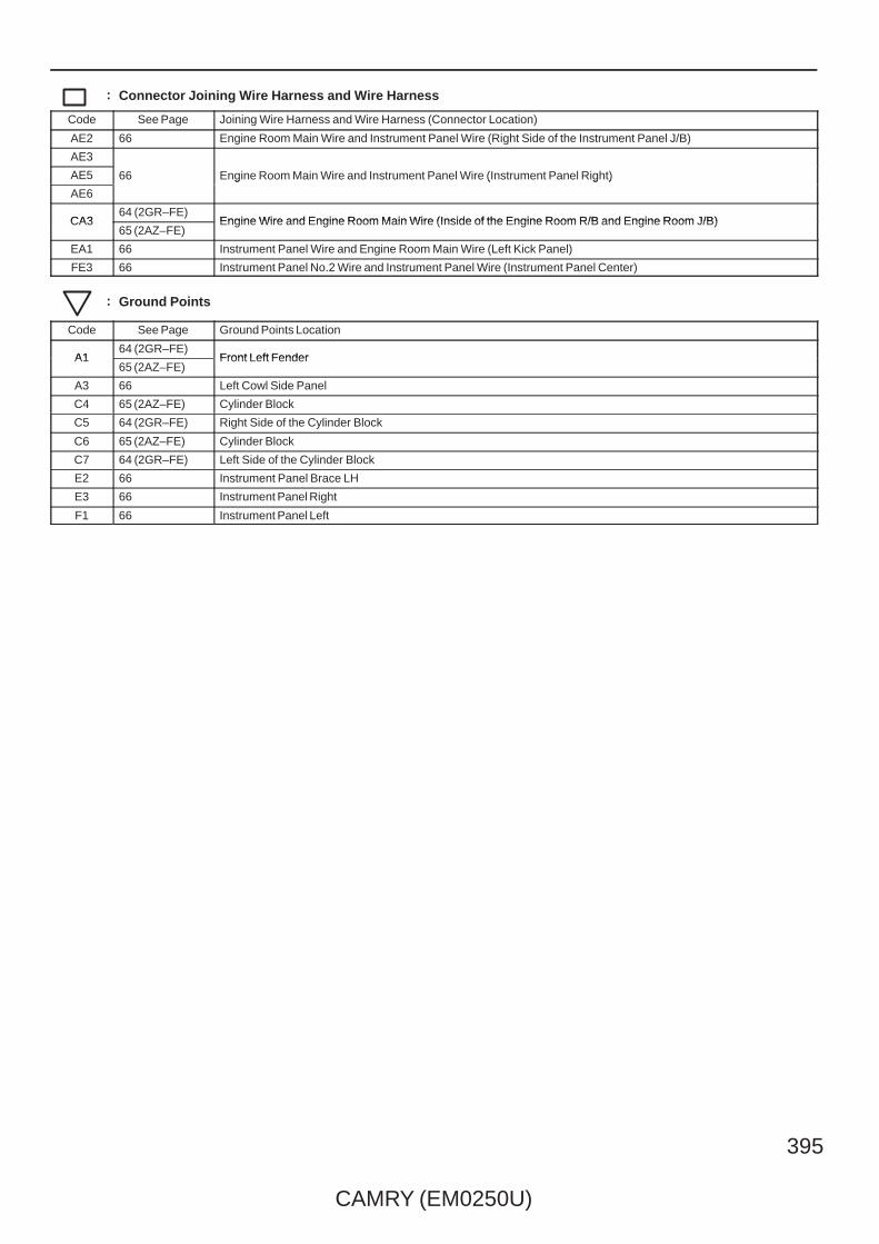
CAMRY (EM0250U)
395
: Connector Joining Wire Harness and Wire Harness
Code See Page Joining Wire Harness and Wire Harness (Connector Location)
AE2 66 Engine Room Main Wire and Instrument Panel Wire (Right Side of the Instrument Panel J/B)
AE3
66 Engine Room Main Wire and Instrument Panel Wire (Instrument Panel Right)AE5 66 Engine Room Main Wire and Instrument Panel Wire (Instrument Panel Right)
AE6
66 Engine Room Main Wire and Instrument Panel Wire (Instrument Panel Right)
CA364 (2GR–FE)
Engine Wire and Engine Room Main Wire (Inside of the Engine Room R/B and Engine Room J/B)CA365 (2AZ–FE)
Engine Wire and Engine Room Main Wire (Inside of the Engine Room R/B and Engine Room J/B)
EA1 66 Instrument Panel Wire and Engine Room Main Wire (Left Kick Panel)
FE3 66 Instrument Panel No.2 Wire and Instrument Panel Wire (Instrument Panel Center)
: Ground Points
Code See Page Ground Points Location
A164 (2GR–FE)
Front Left FenderA165 (2AZ–FE)
Front Left Fender
A3 66 Left Cowl Side Panel
C4 65 (2AZ–FE) Cylinder Block
C5 64 (2GR–FE) Right Side of the Cylinder Block
C6 65 (2AZ–FE) Cylinder Block
C7 64 (2GR–FE) Left Side of the Cylinder Block
E2 66 Instrument Panel Brace LH
E3 66 Instrument Panel Right
F1 66 Instrument Panel Left

396
CAMRY (EM0250U)
I GROUND POINT
RR DEF Relay
(SOL–) C21
(GND)C11
(GND)C12
(GND)C38
(GND)C13
(GND)C14
(GND)C39
(E)FAN NO. 2Relay
(–S)FAN MAINRelay
(E)A7
(E)A8
(E)A45
(E01)
(E1) C56
(E1)A54
(E)A47
(E)A46
(ME01)C24
(E02)
(GND) C11
C12(GND)
(GND) C13
C14(GND)
CA32
(E)
ST Relay(–S)
C7
1
1
A1
4CA3
CA31 (Shielded)
C57
C4
W–B(2AZ–FE)
W–B(2AZ–FE)
W–B(2AZ–FE)
W–B(2AZ–FE)
B–W
(2AZ–FE)
W–B
(2AZ–FE)
L
(2AZ–FE)
B
(2AZ–FE)
B–W
(2AZ–FE)
W–B
(2GR–FE)
GR
(2GR–FE)
B
(2GR–FE)
W
(2GR–FE)
W–B
(2GR–FE)
B
(2GR–FE)
W
(2GR–FE)
W–B
(2GR–FE)
B–W
(2GR–FE)
BR
(2GR–FE)
W–B
(2GR–FE)W–B
W–B
(2GR–FE)
W–B
(2AZ–FE)
W–B
W–B
(2GR–FE)
BR
W–B
BR
W–B
W–B
W
W–B
W–B
1
1
2
1
3
W–B
1E11
(SGND)
W–B
BR
(E1) C55(2GR–FE)
W–B
(E05)W
(2GR–FE)
(E02)B–W
(2GR–FE)
5
6
4
W B
( 2G
R–F
E)
( 2G
R–F
E)
A/F Relay
( 2A
Z–FE
)
Headlamp (LH Low)
Turn Signal andParking Lamp (Front LH)
Side Marker Lamp(Front LH)
Cooling Fan ECU
Radiator Fan Motor
Headlamp (LH High)
Ignition Coil(No. 1)
Ignition Coil (No. 1)
Ignition Coil(No. 3)
Ignition Coil (No. 3)
Ignition Coil(No. 2)
Ignition Coil (No. 2)
Ignition Coil(No. 4)
Ignition Coil (No. 4)
A/C Compressor
Engine ControlModule
Ignition Coil (No. 5)
Ignition Coil (No. 6)
Engine ControlModule
TransmissionControl ECU
Junc
tion
Con
nect
or
BRCA312
EFI Relay(L)1E
10
W–B
W–B
BR
BR
( 2G
R–F
E)
BR
(2AZ–FE)
BR
(2GR–FE)
W–B
Light ControlCircuit
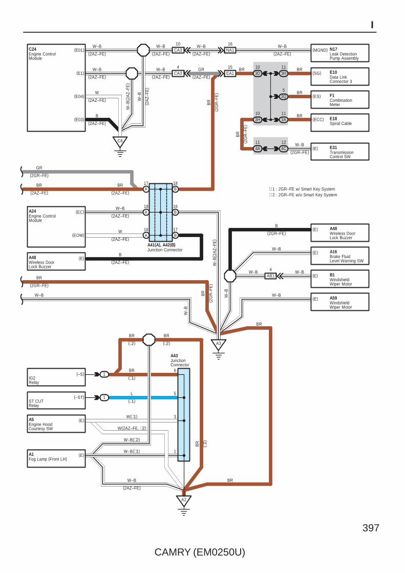
CAMRY (EM0250U)
397
I
(EOM)
A24 (EC)
C6
(E03)
(E04)
(E1)
C24 (E01)
E10(SG)
(ES) F1
E18(ECC)
(E) B1
A17
A18
A16
B18
B16
3H11
53Q
3A11
A3
A41(A), A42(B)
BR
BR
BR
W–B
(2AZ–FE)
W–B
(2AZ–FE)
W
(2AZ–FE)
B
(2AZ–FE)
W–B
( 2A
Z–FE
)
W–B
W–B
(2AZ–FE)
W
(2AZ–FE)
BR
(2AZ–FE)
GR
(2GR–FE)
4AB1
W–B
( 2A
Z–FE
)
B17
(E)(2AZ–FE)
B
(E)
(E)
B
(2GR–FE)
W–B
A48
A16
W–B
A48
N17(MGND)10
CA3 NA116
EA1154
CA3 3D10
124C
114A E31(E)
W–B
3H10
(–S)IG2Relay
(–ST)ST CUTRelay
(E)A5
(E)A1
1
1
A2
W–B
(2AZ–FE)
W–B
(2AZ–FE)
W–B
(2AZ–FE)
W–B
(2AZ–FE)
GR
(2AZ–FE)
BR
( 2G
R–F
E)
BR
W–B
W–B
( 2A
Z–FE
)
BR
BRW–B
W–B(∗1)
W–B(∗2)
W(2AZ–FE, ∗2)
W(∗1)
L
BR
BR BR
1
3
5
6
(∗2)
(∗1)
(2AZ–FE)
(∗1)
(∗2)
A43
BR
( ∗2)
BR
( 2G
R–F
E)
∗ 1 : 2GR–FE w/ Smart Key System∗ 2 : 2GR–FE w/o Smart Key System
(2GR–FE)
Fog Lamp (Front LH)
Brake FluidLevel Warning SW
Engine ControlModule
Junction Connector
JunctionConnector
Wireless DoorLock Buzzer
Wireless DoorLock Buzzer
Engine HoodCourtesy SW
WindshieldWiper Motor
Engine ControlModule
Data LinkConnector 3
Spiral Cable
TransmissionControl SW
CombinationMeter
Leak DetectionPump Assembly
BR
(2AZ–FE)
BR
(2GR–FE)
W–B BR
W–B
( 2G
R–F
E)
(E) A59W–B
WindshieldWiper Motor

398
CAMRY (EM0250U)
I GROUND POINT
(E) A52
A25(GND2)
(GND2) A26
(E04)
(ME01) C55
A26 (GND1)
A25 (GND1)
A29 (E)
A49 (E)
A5
A6 A4
(GND)E39
E30(E2)
(E) T6
T8(E)
C4
B4
B1
O20(A), T18(B)
A5
EO210
E3 E1
W–B
(∗3)
W–B
W–B
W–B
W–B
W–B W–B
W–B
(w/o VSC)
W–B
(w/ VSC)
W–BW–B
(w/ VSC)
W–B
(w/o VSC)
W–B
BR
BR
W–B
W–B
W–B
(2GR–FE) B
(2GR–FE)
W
(2GR–FE)
( ∗3)
( ∗3)
5IE
3IM
(E01)C55
CA31016
NA1W–B
(2GR–FE)
W–B
(2GR–FE)
W–B
(2GR–FE)N17
(E) A34(E)
(E)
A51
A50
W–B
(GND)W–B
(∗1)E51
W–B
(∗1)
W–B
(∗1)
W–B
(∗1)
(MGND)
B
W–BW
–B
IG10
(E03)B
(2GR–FE)
(GND3) E8
(GND) E52
(COM)
54L
44E
54E
54H
W–B
∗ 1 : 2GR–FE w/ Smart Key System∗ 3 : w/ Power Seat∗ 4 : w/ Sliding Roof∗ 5 : w/o Sliding Roof∗ 6 : w/ Jam Protection∗ 7 : w/o Jam Protection
W–B
( 2G
R–F
E)
Skid Control ECUwith Actuator
Skid Control ECUwith Actuator
Skid Control ECUwith Actuator
Skid Control ECUwith Actuator
Headlamp (RH High)
Fog Lamp(Front RH)
Headlamp (RH Low)
Turn Signal andParking Lamp (Front RH)
Side Marker Lamp(Front RH)
Washer LevelWarning SW
Engine ControlModule
Engine ControlModule
Airbag SensorAssembly Center
Blower Motor Steering Lock ECU
Power SW
Main Body ECU
Canister PumpModule
JunctionConnector
Seat Heater (RH)
Power Seat SW(Front Passenger' sSeat)
B3
(GND) T10OccupantClassificationECU
W–B
(∗3)
(∗3)

CAMRY (EM0250U)
399
I
(–)
E29
H2
Q9(E)
(GND)
(E) Q11
E12
(E)E58
(E)
(GND2)
H8
IG1 Relay
(E)
H5
(GND1)Main Body ECU
PWR Relay
(GND)W2
ACC Relay
TAIL Relay
8 HW1
Main Body ECU
(E1) E30
(E)
IR1
IM9
18EQ1
34D
44F
4L1
E49
W–B
W–B
W
W
(∗5)
W–B
W–B
W–B
W–B
W–B
W–B
W–B
W–B
W–B
W–B
BR
(∗1)
W–B
(E)E35W–B
(A/T)
W–B
( ∗1)
17HE2
W–B
W–B
W–B
1
5
4
8
11
10
W–B
4F3W–B
(∗1)
(∗1)
(GND)E50
W–B
W–B
W–B
W–B
(E)
Q3(E)
(E)
Q6W–B
(∗4)
W–B(∗4)
EQ111
(–)
(E)
(E)
(E)
17IE2
W–B
I3
I7
I5
M1
(∗7)(∗6)18 IM1
13 IM2
6
(E)
(E)
Q1
Q2
W
(∗5)
W
(∗5)
13
(∗6)
W–B
(GND)
W
W
(∗5)
W ( ∗5)
7W–B(E)E55
W–B
(ESS)E17
(GND)E34
4B2
(GND)X2 IX18
IF10
IE1
2
W–B
(w/ VSC TMC Made)
W–B
(w/ VSC)
BR
W–B
( ∗1)
9 W–BW–B
W–B
W–B
W–B
W–B
(∗1)
Ion Generator
Steering Sensor
Power Outlet Socket(Front)
Airbag SensorAssembly Center
Yaw Rate Sensor
Power Outlet Socket(Rear)
Junc
tion
Con
nect
or
ID Code Box
Certification ECU
Seat Heater SW
Outer RearView Mirror (RH)
Door Lock Control SW
Door Lock Assembly(Front Passenger' s Side)
Outer RearView Mirror (LH)
Power WindowRegulator Motor(Front LH)
Door Lock Assembly(Driver' s Side)
Power Window Master SW
Vanity Lamp SW(LH)
Map Lamp (LH)
Vanity Lamp SW(RH)
Inner RearView Mirror
Overhead J/B
Room Lamp(Center)
Electrical KeyOscillator (Front Door RH)
Electrical KeyOscillator (Front Door LH)
4 FE3
12
(GND)E65W–B
(w/ VSC TMMK Made)Yaw Rate Sensor
W–B
(∗1)(SGND)E51 4A
2W–B
Steering Lock ECU
W–B
(∗4)Q13Sliding RoofControl ECUand Motor
(E) Q10Map Lamp (RH)
W ( ∗5)
4B1

400
CAMRY (EM0250U)
I GROUND POINT
(KLS–)
(GND)
E24
E38
E2
E3 (E)
E10
J5(E)
(GND) O17
(UN–)E22
E152
3B
23A
(GND)
(CG) 3H3
3I3
13K
3M2
O21
E19(EW)
4JO1
N27
( A) ,
U11
( B)
O1
EO19
1B
2B
A5
3B
B4
EN210
U7(E)
(R1)
U8(E)
(E) U6
(E2)F1
(GND1)F3
(GND)F16
(E)F5
3Q7
3R8
3S2
3T2
F1
3U2
W–B
W–B
W–B
W–B
W–B
W–B
(∗3)
W–B
(∗3)
W–B
(∗3)
W–B
W–BW–B
W–B
W–B
W–B
(∗3)
W–B
W–B
W–B
W–B
W–B
W–B
W–B
(∗10)
W–B
W–B
5
8
W–B
(∗10)
W–B
W–B
3O1
3N1
W–B
(∗1)
E60
(GND) O4W–B
(Manual Seat)
W–B
(GND) O18
E53
E57
E32W–B
(∗10)3K2
3
(∗10)
6 W–B
(∗1)
W–BE14
W–BE21
3F3
3G3
3C3
W–B W–B
W–B
( ∗3)
Data Link Connector 3 Turn SignalFlasher
Transponder Key ECU
WindshieldWiper SW Assembly
Headlamp DimmerSW Assembly
Unlock Warning SW
Key InterlockSolenoid
Outer Mirror SW
Shift LockControl ECU
A/C Amplifier
Tire PressureWarning SW (Reset)
Shift LockControl ECU
Tire PressureWarning ECU
Combination Meter
A/C Control Assembly
Clock
Glove Box Lamp
Door Lock Assembly(Rear RH)
Junc
tion
Con
nect
or
Door ControlReceiver
Door ControlReceiver
Junc
tion
Con
nect
or
OccupantClassificationECU
Seat Heater (LH)
Power Seat SW(Driver' s Seat)
Power Seat SW(Driver' s Seat Lumbar Support Control)
(E)
(E)
(EL)
(E)
(E)
(GND)
(∗3)
(∗10)

CAMRY (EM0250U)
401
I
(Shielded)
C5
F6
S15
(GND)
N29
S5 (ACT–)
S1 (E)
S6 (E)
S2 (E)
S1
S3 (E)
S4 (E)
S10(E)
(E) S11
S12(E)
(E) S13
(E) N16
K5(E)
(E) P1
P1
4KN1
N1
F2
W–B
W–B
W–B
W–B
W–B
W–B
W–B
W–B
W–B
W–B W–B
W–B
W–B
W–B W–B
W–B
BR
BR
( 2G
R–F
E)
B
( 2G
R–F
E)
W–B
2
3
7
6
2
9
1
(∗8)
BR
(∗12)
BR
(∗11)
(GND)
(GND)
F11
F9
W–B
( ∗11
)
F3
W–B
W–B
W–B
(∗1)
W–B
(∗1)
(E)
(E)
S8
S9
SN11
(Shielded)
( Shi
elde
d)
(GND)F20
(E)
BR
BR
(∗9)
(∗9)
W–B
∗ 1 : 2GR–FE w/ Smart Key System∗ 3 : w/ Power Seat
∗10 : w/o Smart Key System∗11 : 8 Speaker w/ Navigation System
∗ 8 : 6 Speaker
∗12 : 8 Speaker w/o Navigation System
5
Radio ReceiverAssembly
Stereo ComponentAmplifier
Radio ReceiverAssembly
NavigationReceiver Assembly
Door Lock Assembly(Rear LH)
Center Stop Lamp
Junc
tion
Con
nect
or
Rear WindowDefogger
License Plate Lamp (RH)
Turn Signal Lamp(Rear LH)
Rear CombinationLamp (LH)
Rear CombinationLamp (RH)
Turn Signal Lamp(Rear RH)
Junc
tion
Con
nect
or
Rear Combination Lamp (RH)
Rear Combination Lamp (LH)
License Plate Lamp (LH)
Door Lock Assembly(Luggage)
Luggage CompartmentDoor Lock Cylinder
LuggageCompartment DoorLock Cylinder
LuggageElectrical Key SW
( ∗12
)
W–B
( Shi
elde
d)
F26(GND)Radio ReceiverAssembly
(∗12)
BR
N10(E)Fuel Suction Pumpand Gage Assembly
W–B W–B W–B
(∗10)
∗ 9 : 8 Speaker

402
CAMRY (EM0250U)
I GROUND POINT
: Parts Location
Code See Page Code See Page Code See Page
A41 A 59 E49 57 O21 60
A42 B 59 N27 A 62 (*1) S15 61
A43 49 (2GR–FE) N29 60 T18 B 62 (*1)
C57 51 (2GR–FE) O20 A 62 (*1) U11 B 62 (*1)
: Relay Blocks
Code See Page Relay Blocks (Relay Block Location)
1 22 Engine Room R/B (Engine Compartment Left)
: Junction Block and Wire Harness Connector
Code See Page Junction Block and Wire Harness (Connector Location)
1E 25 Engine Room Main Wire and Engine Room J/B (Engine Compartment Left)
3A
36 Instrument Panel Wire and J/B No.3 (Behind the Combination Meter)
3B
36 Instrument Panel Wire and J/B No.3 (Behind the Combination Meter)
3C
36 Instrument Panel Wire and J/B No.3 (Behind the Combination Meter)
3D
36 Instrument Panel Wire and J/B No.3 (Behind the Combination Meter)
3F
36 Instrument Panel Wire and J/B No.3 (Behind the Combination Meter)3G
36 Instrument Panel Wire and J/B No.3 (Behind the Combination Meter)3H
36 Instrument Panel Wire and J/B No.3 (Behind the Combination Meter)
3I
3K
3M
3N
3O
3Q
36 Instrument Panel No.2 Wire and J/B No.3 (Behind the Combination Meter)
3R
36 Instrument Panel No.2 Wire and J/B No.3 (Behind the Combination Meter)3S 36 Instrument Panel No.2 Wire and J/B No.3 (Behind the Combination Meter)
3T
36 Instrument Panel No.2 Wire and J/B No.3 (Behind the Combination Meter)
3U
4A
42 Instrument Panel Wire and J/B No.4 (Instrument Panel Brace Center)
4B
42 Instrument Panel Wire and J/B No.4 (Instrument Panel Brace Center)
4C
42 Instrument Panel Wire and J/B No.4 (Instrument Panel Brace Center)4D
42 Instrument Panel Wire and J/B No.4 (Instrument Panel Brace Center)4E
42 Instrument Panel Wire and J/B No.4 (Instrument Panel Brace Center)
4F
4H
4L
IE30
Instrument Panel Wire and Instrument Panel J/B (Cowl Side Left)
IF30
Instrument Panel Wire and Instrument Panel J/B (Cowl Side Left)IG 31 Instrument Panel Wire and Instrument Panel J/B (Cowl Side Left)
IM30
Instrument Panel Wire and Instrument Panel J/B (Cowl Side Left)
IR30
* 1 : w/ Power Seat * 2 : w/o Power Seat

CAMRY (EM0250U)
403
I
: Connector Joining Wire Harness and Wire Harness
Code See Page Joining Wire Harness and Wire Harness (Connector Location)
AB164 (2GR–FE)
Engine Room Main Wire and Engine Room No.2 Wire (Near the Windshield Wiper Motor)AB165 (2AZ–FE)
Engine Room Main Wire and Engine Room No.2 Wire (Near the Windshield Wiper Motor)
CA364 (2GR–FE)
Engine Wire and Engine Room Main Wire (Inside of the Engine Room R/B and Engine Room J/B)CA365 (2AZ–FE)
Engine Wire and Engine Room Main Wire (Inside of the Engine Room R/B and Engine Room J/B)
EA1 66 Instrument Panel Wire and Engine Room Main Wire (Left Kick Panel)
EN2 66 Instrument Panel Wire and Floor Wire (Left Kick Panel)
EO166 Instrument Panel Wire and Floor No.2 Wire (Right Kick Panel)
EO266 Instrument Panel Wire and Floor No.2 Wire (Right Kick Panel)
EQ1 66 Instrument Panel Wire and Roof Wire (Lower Part of Front Pillar LH)
FE3 66 Instrument Panel No.2 Wire and Instrument Panel Wire (Instrument Panel Center)
HE2 66 Front Door RH Wire and Instrument Panel Wire (Right Kick Panel)
HW1 67 Front Door RH Wire and Electrical Key Wire Harness RH (Inside of the Front Door RH)
IE2 66 Front Door LH Wire and Instrument Panel Wire (Left Kick Panel)
IM167 Front Door LH Wire and Front Door LH No.2 Wire (Inside of the Front Door LH)
IM267 Front Door LH Wire and Front Door LH No.2 Wire (Inside of the Front Door LH)
IX1 67 Front Door LH Wire and Electrical Key Wire Harness LH (Inside of the Front Door LH)
JO1 67 Rear Door No.1 Wire and Floor No.2 Wire (Right Center Pillar)
KN1 67 Rear Door No.2 Wire and Floor Wire (Left Center Pillar)
NA1 66 Floor Wire and Engine Room Main Wire (Left Kick Panel)
QR1 67 Roof Wire and Roof No.2 Wire (Near the Overhead J/B)
SN1 67 Luggage Room Wire and Floor Wire (Luggage Room Left)
: Ground Points
Code See Page Ground Points Location
A164 (2GR–FE)
Front Left Fender
A165 (2AZ–FE)
Front Left Fender
A264 (2GR–FE)
Front Left Fender
A265 (2AZ–FE)
A3 66 Left Cowl Side Panel
A464 (2GR–FE)
Near the Skid Control ECU with ActuatorA465 (2AZ–FE)
Near the Skid Control ECU with Actuator
A564 (2GR–FE)
Front Right FenderA565 (2AZ–FE)
Front Right Fender
A6 66 Right Cowl Side Panel
C464 (2GR–FE) Cylinder Head
C465 (2AZ–FE) Cylinder Block
C5 64 (2GR–FE) Right Side of the Cylinder Block
C6 65 (2AZ–FE) Cylinder Block
C7 64 (2GR–FE) Left Side of the Cylinder Block
E1 66 Instrument Panel Left
E2 66 Instrument Panel Brace LH
E3 66 Instrument Panel Right
F1 66 Instrument Panel Left
F2 66 Instrument Panel Brace RH
F3 66 Under the Front Passenger’s Seat
N1 67 Left Rear Quarter Panel
O167 Right Rear Quarter Panel
P167 Right Rear Quarter Panel
S1 67 Lower Back Panel Center
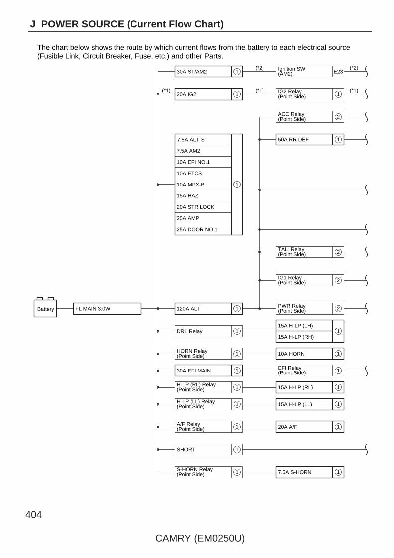
404
CAMRY (EM0250U)
J POWER SOURCE (Current Flow Chart)
The chart below shows the route by which current flows from the battery to each electrical source(Fusible Link, Circuit Breaker, Fuse, etc.) and other Parts.
Battery 120A ALT
HORN Relay(Point Side)
A/F Relay(Point Side)
IG2 Relay(Point Side)
ACC Relay(Point Side)
TAIL Relay(Point Side)
IG1 Relay(Point Side)
PWR Relay(Point Side)
H-LP (LL) Relay(Point Side)
FL MAIN 3.0W
20A IG2
25A AMP
25A DOOR NO.1
20A STR LOCK
15A HAZ
10A ETCS
7.5A ALT-S
7.5A AM2
10A MPX-B
10A EFI NO.1
DRL Relay
SHORT
50A RR DEF
15A H-LP (LH)
15A H-LP (RH)
10A HORN
30A EFI MAIN
20A A/F
1
1
1
1
1
1
1
2
1
2
2
2
1
1
1
1
15A H-LP (RL)H-LP (RL) Relay(Point Side) 1 1
1
S-HORN Relay(Point Side) 7.5A S-HORN1 1
1
(*1) (*1)
(*2)
(*1)
Ignition SW(AM2)30A ST/AM2 1
(*2)E23
EFI Relay(Point Side)
15A H-LP (LL)
1
1

CAMRY (EM0250U)
405
J
4
Code or LocationParts
Electrical Source
7.5A DRL
Starter S1
Location
Example
RR DEF Relay(Point Side)
15A INJ
10A IGN
7.5A GAUGE NO.2
15A TAIL
7.5A PANEL
30A POWER
25A RR DOOR LH
25A RR DOOR RH
15A RADIO NO.1
10A ECU-B NO.1
10A DOME
50A ABS No.1
50A FAN MAIN
10A MIR HTR
50A HTR
40A RDI FAN
30A ABS No.2
40A CDS FAN
25A WIP
20A S-HTR
10A ECU IG NO.1
10A GAUGE NO.1
10A WASH
10A A/C NO.2
7.5A ECU IG NO.2
10A EFI NO.3
15A EFI NO.2
* 1:2GR-FE* 2:2AZ-FE
20A PWR OUTLET
7.5A ECU-ACC
7.5A RADIO NO.2
30A P/SEAT
30A S/ROOF
7.5A A/C
7.5A AM1
10A STOP
7.5A OBD
25A PWR
15A FR FOG
25A DOOR NO.2
2
1
2
2
1
1
2
1
2
2
2
1 : Engine Room R/B and Engine Room J/B (See Page 22)
2 : Instrument Panel J/B (See Page 30)
(*1)
(*2)
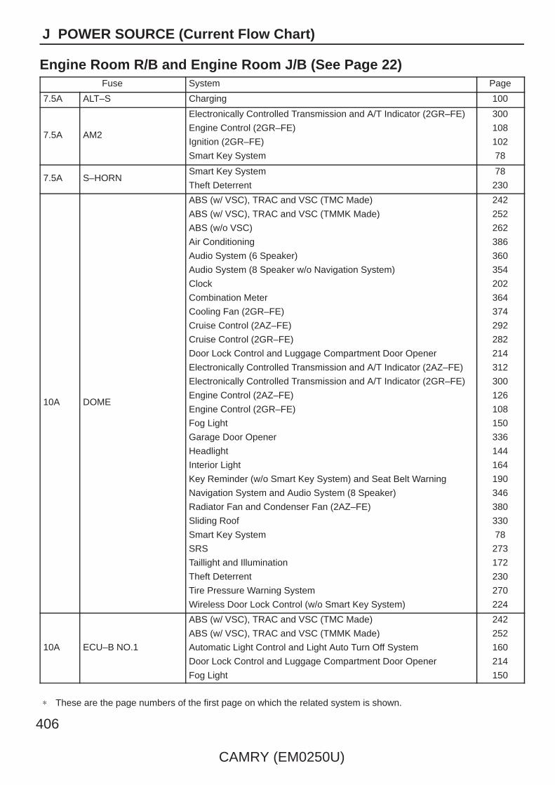
406
CAMRY (EM0250U)
J POWER SOURCE (Current Flow Chart)
Engine Room R/B and Engine Room J/B (See Page 22)Fuse System Page
7.5A ALT–S Charging 100
7.5A AM2
Electronically Controlled Transmission and A/T Indicator (2GR–FE)
Engine Control (2GR–FE)
Ignition (2GR–FE)
Smart Key System
300
108
102
78
7.5A S–HORNSmart Key System
Theft Deterrent
78
230
10A DOME
ABS (w/ VSC), TRAC and VSC (TMC Made)
ABS (w/ VSC), TRAC and VSC (TMMK Made)
ABS (w/o VSC)
Air Conditioning
Audio System (6 Speaker)
Audio System (8 Speaker w/o Navigation System)
Clock
Combination Meter
Cooling Fan (2GR–FE)
Cruise Control (2AZ–FE)
Cruise Control (2GR–FE)
Door Lock Control and Luggage Compartment Door Opener
Electronically Controlled Transmission and A/T Indicator (2AZ–FE)
Electronically Controlled Transmission and A/T Indicator (2GR–FE)
Engine Control (2AZ–FE)
Engine Control (2GR–FE)
Fog Light
Garage Door Opener
Headlight
Interior Light
Key Reminder (w/o Smart Key System) and Seat Belt Warning
Navigation System and Audio System (8 Speaker)
Radiator Fan and Condenser Fan (2AZ–FE)
Sliding Roof
Smart Key System
SRS
Taillight and Illumination
Theft Deterrent
Tire Pressure Warning System
Wireless Door Lock Control (w/o Smart Key System)
242
252
262
386
360
354
202
364
374
292
282
214
312
300
126
108
150
336
144
164
190
346
380
330
78
273
172
230
270
224
10A ECU–B NO.1
ABS (w/ VSC), TRAC and VSC (TMC Made)
ABS (w/ VSC), TRAC and VSC (TMMK Made)
Automatic Light Control and Light Auto Turn Off System
Door Lock Control and Luggage Compartment Door Opener
Fog Light
242
252
160
214
150
∗ These are the page numbers of the first page on which the related system is shown.

CAMRY (EM0250U)
407
J
Fuse System Page
10A ECU–B NO.1
Headlight
Interior Light
Key Reminder (w/o Smart Key System) and Seat Belt Warning
Power Window
Sliding Roof
SRS
Taillight and Illumination
Theft Deterrent
Wireless Door Lock Control (w/o Smart Key System)
144
164
190
206
330
273
172
230
224
10A EFI NO.1
Cruise Control (2AZ–FE)
Cruise Control (2GR–FE)
Electronically Controlled Transmission and A/T Indicator (2AZ–FE)
Electronically Controlled Transmission and A/T Indicator (2GR–FE)
Engine Control (2AZ–FE)
Engine Control (2GR–FE)
Engine Immobiliser System (w/o Smart Key System)
Smart Key System
292
282
312
300
126
108
138
78
10A EFI NO.3
Electronically Controlled Transmission and A/T Indicator (2AZ–FE)
Electronically Controlled Transmission and A/T Indicator (2GR–FE)
Engine Control (2AZ–FE)
Engine Control (2GR–FE)
312
300
126
108
10A ETCS
Cruise Control (2AZ–FE)
Cruise Control (2GR–FE)
Electronically Controlled Transmission and A/T Indicator (2AZ–FE)
Electronically Controlled Transmission and A/T Indicator (2GR–FE)
Engine Control (2AZ–FE)
Engine Control (2GR–FE)
292
282
312
300
126
108
10A HORN
Horn
Smart Key System
Theft Deterrent
204
78
230
10A MPX–B
ABS (w/ VSC), TRAC and VSC (TMC Made)
ABS (w/ VSC), TRAC and VSC (TMMK Made)
ABS (w/o VSC)
Air Conditioning
Audio System (6 Speaker)
Audio System (8 Speaker w/o Navigation System)
Combination Meter
Cooling Fan (2GR–FE)
Cruise Control (2AZ–FE)
Cruise Control (2GR–FE)
Door Lock Control and Luggage Compartment Door Opener
Electronically Controlled Transmission and A/T Indicator (2AZ–FE)
Electronically Controlled Transmission and A/T Indicator (2GR–FE)
Engine Control (2AZ–FE)
242
252
262
386
360
354
364
374
292
282
214
312
300
126
∗ These are the page numbers of the first page on which the related system is shown.
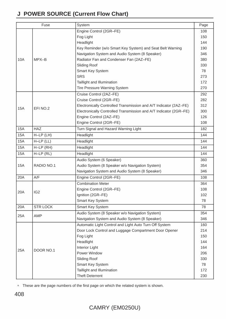
408
CAMRY (EM0250U)
J POWER SOURCE (Current Flow Chart)
Fuse System Page
10A MPX–B
Engine Control (2GR–FE)
Fog Light
Headlight
Key Reminder (w/o Smart Key System) and Seat Belt Warning
Navigation System and Audio System (8 Speaker)
Radiator Fan and Condenser Fan (2AZ–FE)
Sliding Roof
Smart Key System
SRS
Taillight and Illumination
Tire Pressure Warning System
108
150
144
190
346
380
330
78
273
172
270
15A EFI NO.2
Cruise Control (2AZ–FE)
Cruise Control (2GR–FE)
Electronically Controlled Transmission and A/T Indicator (2AZ–FE)
Electronically Controlled Transmission and A/T Indicator (2GR–FE)
Engine Control (2AZ–FE)
Engine Control (2GR–FE)
292
282
312
300
126
108
15A HAZ Turn Signal and Hazard Warning Light 182
15A H–LP (LH) Headlight 144
15A H–LP (LL) Headlight 144
15A H–LP (RH) Headlight 144
15A H–LP (RL) Headlight 144
15A RADIO NO.1
Audio System (6 Speaker)
Audio System (8 Speaker w/o Navigation System)
Navigation System and Audio System (8 Speaker)
360
354
346
20A A/F Engine Control (2GR–FE) 108
20A IG2
Combination Meter
Engine Control (2GR–FE)
Ignition (2GR–FE)
Smart Key System
364
108
102
78
20A STR LOCK Smart Key System 78
25A AMPAudio System (8 Speaker w/o Navigation System)
Navigation System and Audio System (8 Speaker)
354
346
25A DOOR NO.1
Automatic Light Control and Light Auto Turn Off System
Door Lock Control and Luggage Compartment Door Opener
Fog Light
Headlight
Interior Light
Power Window
Sliding Roof
Smart Key System
Taillight and Illumination
Theft Deterrent
160
214
150
144
164
206
330
78
172
230
∗ These are the page numbers of the first page on which the related system is shown.
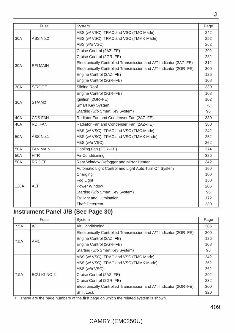
CAMRY (EM0250U)
409
J
Fuse System Page
30A ABS No.2
ABS (w/ VSC), TRAC and VSC (TMC Made)
ABS (w/ VSC), TRAC and VSC (TMMK Made)
ABS (w/o VSC)
242
252
262
30A EFI MAIN
Cruise Control (2AZ–FE)
Cruise Control (2GR–FE)
Electronically Controlled Transmission and A/T Indicator (2AZ–FE)
Electronically Controlled Transmission and A/T Indicator (2GR–FE)
Engine Control (2AZ–FE)
Engine Control (2GR–FE)
292
282
312
300
126
108
30A S/ROOF Sliding Roof 330
30A ST/AM2
Engine Control (2GR–FE)
Ignition (2GR–FE)
Smart Key System
Starting (w/o Smart Key System)
108
102
78
96
40A CDS FAN Radiator Fan and Condenser Fan (2AZ–FE) 380
40A RDI FAN Radiator Fan and Condenser Fan (2AZ–FE) 380
50A ABS No.1
ABS (w/ VSC), TRAC and VSC (TMC Made)
ABS (w/ VSC), TRAC and VSC (TMMK Made)
ABS (w/o VSC)
242
252
262
50A FAN MAIN Cooling Fan (2GR–FE) 374
50A HTR Air Conditioning 386
50A RR DEF Rear Window Defogger and Mirror Heater 342
120A ALT
Automatic Light Control and Light Auto Turn Off System
Charging
Fog Light
Power Window
Starting (w/o Smart Key System)
Taillight and Illumination
Theft Deterrent
160
100
150
206
96
172
230
Instrument Panel J/B (See Page 30)Fuse System Page
7.5A A/C Air Conditioning 386
7.5A AM1
Electronically Controlled Transmission and A/T Indicator (2GR–FE)
Engine Control (2AZ–FE)
Engine Control (2GR–FE)
Starting (w/o Smart Key System)
300
126
108
96
7.5A ECU IG NO.2
ABS (w/ VSC), TRAC and VSC (TMC Made)
ABS (w/ VSC), TRAC and VSC (TMMK Made)
ABS (w/o VSC)
Cruise Control (2AZ–FE)
Cruise Control (2GR–FE)
Electronically Controlled Transmission and A/T Indicator (2GR–FE)
Shift Lock
242
252
262
292
282
300
320
∗ These are the page numbers of the first page on which the related system is shown.
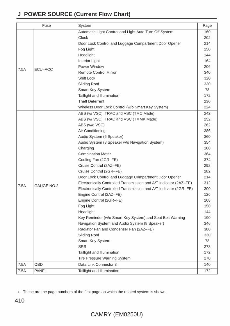
410
CAMRY (EM0250U)
J POWER SOURCE (Current Flow Chart)
Fuse System Page
7.5A ECU–ACC
Automatic Light Control and Light Auto Turn Off System
Clock
Door Lock Control and Luggage Compartment Door Opener
Fog Light
Headlight
Interior Light
Power Window
Remote Control Mirror
Shift Lock
Sliding Roof
Smart Key System
Taillight and Illumination
Theft Deterrent
Wireless Door Lock Control (w/o Smart Key System)
160
202
214
150
144
164
206
340
320
330
78
172
230
224
7.5A GAUGE NO.2
ABS (w/ VSC), TRAC and VSC (TMC Made)
ABS (w/ VSC), TRAC and VSC (TMMK Made)
ABS (w/o VSC)
Air Conditioning
Audio System (6 Speaker)
Audio System (8 Speaker w/o Navigation System)
Charging
Combination Meter
Cooling Fan (2GR–FE)
Cruise Control (2AZ–FE)
Cruise Control (2GR–FE)
Door Lock Control and Luggage Compartment Door Opener
Electronically Controlled Transmission and A/T Indicator (2AZ–FE)
Electronically Controlled Transmission and A/T Indicator (2GR–FE)
Engine Control (2AZ–FE)
Engine Control (2GR–FE)
Fog Light
Headlight
Key Reminder (w/o Smart Key System) and Seat Belt Warning
Navigation System and Audio System (8 Speaker)
Radiator Fan and Condenser Fan (2AZ–FE)
Sliding Roof
Smart Key System
SRS
Taillight and Illumination
Tire Pressure Warning System
242
252
262
386
360
354
100
364
374
292
282
214
312
300
126
108
150
144
190
346
380
330
78
273
172
270
7.5A OBD Data Link Connector 3 140
7.5A PANEL Taillight and Illumination 172
∗ These are the page numbers of the first page on which the related system is shown.
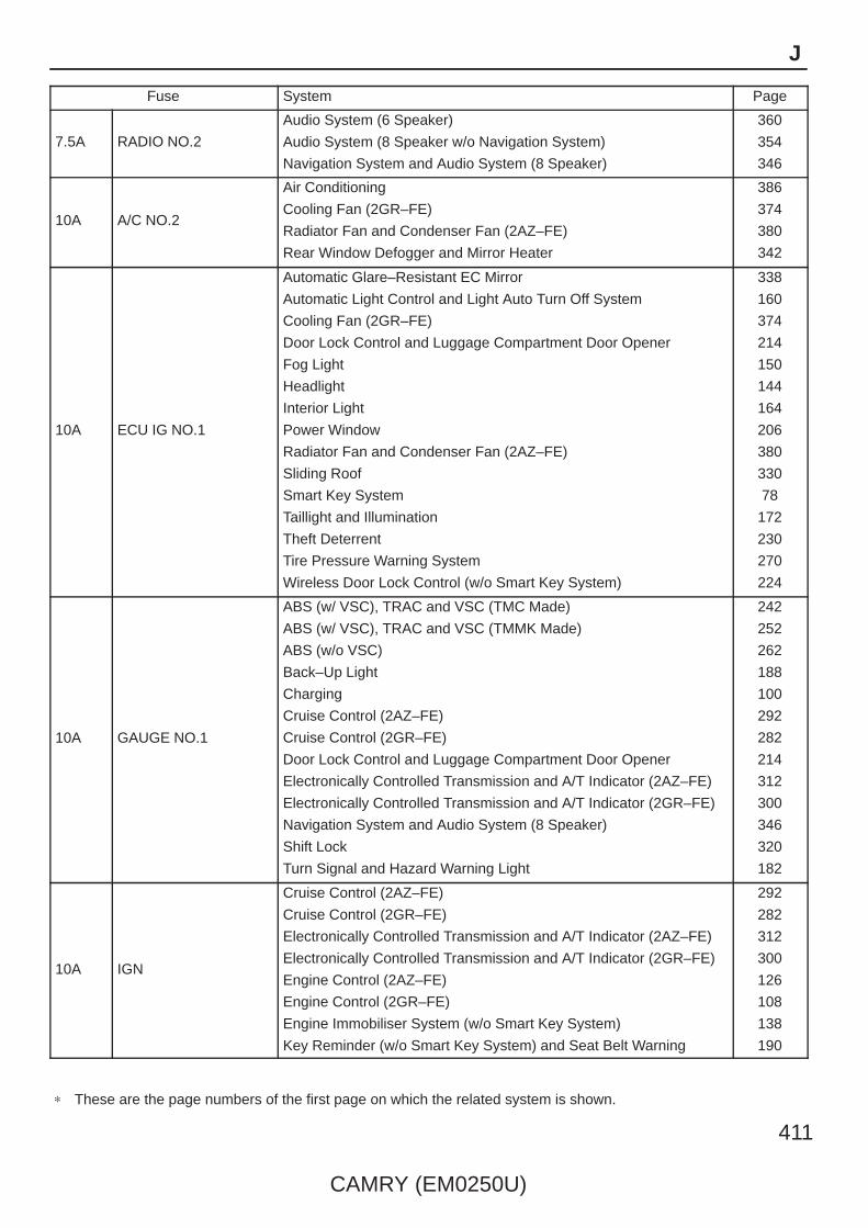
CAMRY (EM0250U)
411
J
Fuse System Page
7.5A RADIO NO.2
Audio System (6 Speaker)
Audio System (8 Speaker w/o Navigation System)
Navigation System and Audio System (8 Speaker)
360
354
346
10A A/C NO.2
Air Conditioning
Cooling Fan (2GR–FE)
Radiator Fan and Condenser Fan (2AZ–FE)
Rear Window Defogger and Mirror Heater
386
374
380
342
10A ECU IG NO.1
Automatic Glare–Resistant EC Mirror
Automatic Light Control and Light Auto Turn Off System
Cooling Fan (2GR–FE)
Door Lock Control and Luggage Compartment Door Opener
Fog Light
Headlight
Interior Light
Power Window
Radiator Fan and Condenser Fan (2AZ–FE)
Sliding Roof
Smart Key System
Taillight and Illumination
Theft Deterrent
Tire Pressure Warning System
Wireless Door Lock Control (w/o Smart Key System)
338
160
374
214
150
144
164
206
380
330
78
172
230
270
224
10A GAUGE NO.1
ABS (w/ VSC), TRAC and VSC (TMC Made)
ABS (w/ VSC), TRAC and VSC (TMMK Made)
ABS (w/o VSC)
Back–Up Light
Charging
Cruise Control (2AZ–FE)
Cruise Control (2GR–FE)
Door Lock Control and Luggage Compartment Door Opener
Electronically Controlled Transmission and A/T Indicator (2AZ–FE)
Electronically Controlled Transmission and A/T Indicator (2GR–FE)
Navigation System and Audio System (8 Speaker)
Shift Lock
Turn Signal and Hazard Warning Light
242
252
262
188
100
292
282
214
312
300
346
320
182
10A IGN
Cruise Control (2AZ–FE)
Cruise Control (2GR–FE)
Electronically Controlled Transmission and A/T Indicator (2AZ–FE)
Electronically Controlled Transmission and A/T Indicator (2GR–FE)
Engine Control (2AZ–FE)
Engine Control (2GR–FE)
Engine Immobiliser System (w/o Smart Key System)
Key Reminder (w/o Smart Key System) and Seat Belt Warning
292
282
312
300
126
108
138
190
∗ These are the page numbers of the first page on which the related system is shown.

412
CAMRY (EM0250U)
J POWER SOURCE (Current Flow Chart)
Fuse System Page
10A IGNSmart Key System
SRS
78
273
10A MIR HTR Rear Window Defogger and Mirror Heater 342
10A STOP
ABS (w/ VSC), TRAC and VSC (TMC Made)
ABS (w/ VSC), TRAC and VSC (TMMK Made)
ABS (w/o VSC)
Cruise Control (2AZ–FE)
Cruise Control (2GR–FE)
Electronically Controlled Transmission and A/T Indicator (2AZ–FE)
Electronically Controlled Transmission and A/T Indicator (2GR–FE)
Engine Control (2AZ–FE)
Engine Control (2GR–FE)
Shift Lock
Smart Key System
Stop Light
242
252
262
292
282
312
300
126
108
320
78
186
10A WASH Wiper and Washer 196
15A FR FOG Fog Light 150
15A INJ
Combination Meter
Engine Control (2AZ–FE)
Ignition (2AZ–FE)
364
126
106
15A TAILFog Light
Taillight and Illumination
150
172
20A PWR OUTLET Power Outlet 200
20A S–HTR Seat Heater 328
25A DOOR NO.2
Automatic Light Control and Light Auto Turn Off System
Door Lock Control and Luggage Compartment Door Opener
Fog Light
Headlight
Interior Light
Power Window
Sliding Roof
Smart Key System
Taillight and Illumination
Theft Deterrent
160
214
150
144
164
206
330
78
172
230
25A PWR Power Window 206
25A RR DOOR LH Power Window 206
25A RR DOOR RH Power Window 206
25A WIP Wiper and Washer 196
30A POWER Power Window 206
30A P/SEATPower Seat (Driver’s Seat)
Power Seat (Front Passenger’s Seat)
322
326
∗ These are the page numbers of the first page on which the related system is shown.

CAMRY (EM0250U)
413
Memo

414
CAMRY (EM0250U)
K CONNECTOR LIST
21
BlackA1
1 2
BlackA2
1
BlackA3
1
BlackA4
12
BlackA5
21
GrayA6
21
BlackA7
1 2
BlackA8
1 2
YellowA13
12
BlackA14
1 2
GrayA16
1 2 3 4 5 6
BlackA17
1
A18
1
3
2
4
BlueA19
1 2
A21
1 2
BlackA22
1
BlackA23
11109876543211918171615141312
222120 3029282726252423
41403938373635343332314948474645444342
525150 6059585756555453
BlackA24
17 181
212 3 4
16 19 20 22 23 24 25 26151413121110985 76
BlackA25

CAMRY (EM0250U)
415
K
31 32
213 4 5 6 7 8 9 10 11 12 13 14 15 1617 18 19 20 21 22 23 24 25 26 27 28 29 30
33 34 35 36 37 38 39 40 41 42 43 44 45 46
BlackA26
1 2 3
BlackA27
1 2
YellowA28
1 2
BlackA29
21
BlackA34
12
GrayA35
1 2
BlackA37
1 2 3 4 5 6
7 8 9 10 11 12
BlueA40
3 5 6 7 9
18 20171614
4
15
8
19
10
21 22
112
1312
1
A41
3 5 6 7 9
18 20171614
4
15
8
19
10
21 22
112
1312
1
A42
1 2 3
654
GrayA43
21
BlackA45
1 2 3
GrayA46
1 2
BlackA47
1 2
BlackA48
21
BlackA49

416
CAMRY (EM0250U)
K CONNECTOR LIST
1 2 3
GrayA50
1 2
BlackA51
1 2
A52
1 2
BlackA53
1 2 3
BlackA54
11109876543211918171615141312
222120 3029282726252423
41403938373635343332314948474645444342
525150 6059585756555453
BlackA55
6 5 4
3 2 1
A56
1 2 3
4 5 6
A57
1 2 3 4 5 6
7 8 9 10 11 12
BlackA58
1 2 3
4 5
BlackA59
254633
12 1426 27 3128 3029 32 3534
13111097 863
5421
1536
1637 38
17 1839
1940
2041
2142
2243
2344
2445
BlackA60
1 2 3
4 5
BlackB1
87 9
21 3 4
65
GrayC1
1 2 3 4 5
BlackC2
1
BlackC3
21
BlackC4
1 2 3 4 5 6
BlackC5
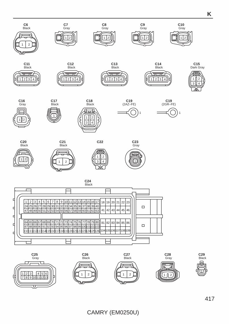
CAMRY (EM0250U)
417
K
1 2
BlackC6
1 2
GrayC7
1 2
GrayC8
1 2
GrayC9
1 2
GrayC10
1 2 3 4
BlackC11
1 2 3 4
BlackC12
1 2 3 4
BlackC13
1 2 3 4
BlackC14
21
3 4
Dark GrayC15
1 2
GrayC16
1
BlackC17
21
3 4
BlackC18
1
(2AZ–FE)C19
1
(2GR–FE)C19
1 2
BlackC20
1 2
BlackC21
21
3 4
C22
1
GrayC23
1 2 3 4 5 6 7 8 9 10 11 12 13 14 15 16 17 18 19 20 21 22 2324 25 26 27 28 29 30 31 32 33 34 35 36 37 38 39 40
41 42 43 44 45 4647 48 49 50 51 52 53 54 55 56 57 58 59 60 61 62 63
64 65 66 67 68 69 70 71 72 73 74 75 76 77 78 79 80 81 82 83 84 85 8687 88 89 90 91 92 93 94 95 96 97 98 99100101102103
104105106107108109110111112113114115116117118119120121122123124125126
BlackC24
1 2 3 4 5 67 8 9 10 11 12 13
GrayC25
1 2
BlackC26
1 2
BlackC27
1 2
GrayC28
1
BlackC29
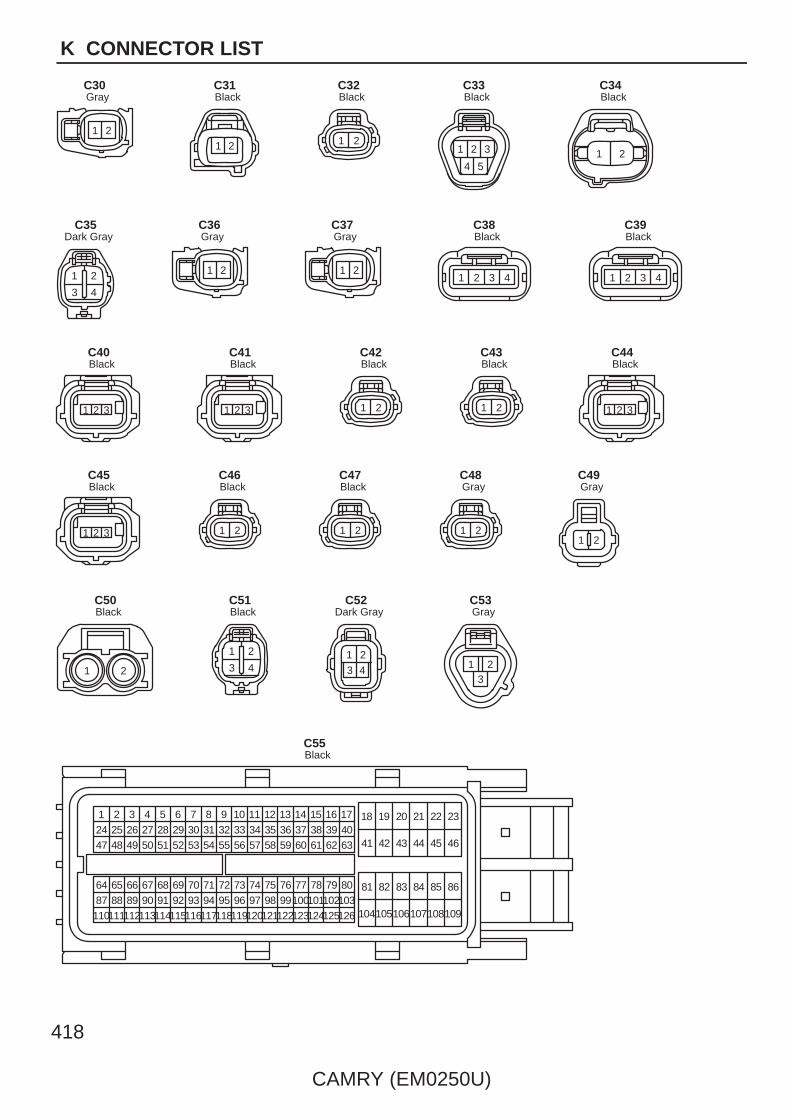
418
CAMRY (EM0250U)
K CONNECTOR LIST
1 2
GrayC30
1 2
BlackC31
1 2
BlackC32
1 2 3
4 5
BlackC33
1 2
BlackC34
21
3 4
Dark GrayC35
1 2
GrayC36
1 2
GrayC37
1 2 3 4
BlackC38
1 2 3 4
BlackC39
1 2 3
BlackC40
1 2 3
BlackC41
1 2
BlackC42
1 2
BlackC43
1 2 3
BlackC44
1 2 3
BlackC45
1 2
BlackC46
1 2
BlackC47
1 2
GrayC48
1 2
GrayC49
1 2
BlackC50
21
3 4
BlackC51
1 2
3 4
Dark GrayC52
213
GrayC53
1 2 3 4 5 6 7 8 9 10 11 12 13 14 15 16 17 18 19 20 21 22 2324 25 26 27 28 29 30 31 32 33 34 35 36 37 38 39 40
41 42 43 44 45 4647 48 49 50 51 52 53 54 55 56 57 58 59 60 61 62 63
64 65 66 67 68 69 70 71 72 73 74 75 76 77 78 79 80 81 82 83 84 85 8687 88 89 90 91 92 93 94 95 96 97 98 99100101102103
104105106107108109110111112113114115116117118119120121122123124125126
BlackC55

CAMRY (EM0250U)
419
K
1 2 3 4 5 6 78 910 11 12 13 14 15 16 17
18 19 20 21 22 23 24 25 26
BlackC56
1 2 3
654
GrayC57
1
D1
1 2
BlackE1
1 2
BlackE2
1 2 3 4 5 6 7 8 9 10
E3
1 2
BlackE5
13 15 16 18
23 26
14 17
24 25
5 6 7 8 9 104321
12 201911
22 282721
E6
2322 2618
107
25
13 14 16 17
19
8
20
9 11 12 15
2421
1 2 3 4 5 6
E7
1 4
5 7 8 10
11 13 14 16
6 9
12 15
2 3
E8
1 2
3 4 5 6
7 8 9 10
E9
16 15 14 13 12 11 10 9
8 7 6 5 4 3 2 1
BlackE10
214365
(Automatic A/C) BlueE11
214365
(Manual A/C) BlackE11
54321
E12
1 2
BlackE13
1 2 34 5 6 7 8
BlackE14
1
6
2
7
3
8 9 10 11 12 13 14
4
15
5
16
E15
1 2 3 4
YellowE16
10987654321
BlackE17

420
CAMRY (EM0250U)
K CONNECTOR LIST
121097641 3 5
1128
BlackE18
1 2 3
45 6
7
E19
1 2 3 4
56 7 8 9
10
E20
1 2 3 4 5 6 7 8 9 10
11 12 13 14 15 16 17 18 19 20
E21
1 2
E22
1 2 3 4
5 6 7 8
E23
1 2
BlackE24
1 2 3 4 5 6 7
BlackE25
21
BlackE27
1 2
E29
11
1 3 4 5 6 7 8 9
13 14 15 16 17 18 19
21 23 24 25 26 27 28 29 30
20
10
22
12
2
YellowE30
8765431 2
E31
8765431 2
E32
1
E33
54321
BlackE34
1 2
E35
1 2
BlackE37
31
21 23
7
27
8
28
9
29
10
30
11
31
12
32
13
33
14
34
18
38
20
40
4
24
17
37
2
22
19
39
5
25
6
26
15
35
16
36
E38
1 2 3
E39
1 2 3 4 5 6
7 8 9 10 11 12
E40
1 2 3 4 5 6
7 8 9 10 11 12
BlueE41
1
2
E42

CAMRY (EM0250U)
421
K
1
2
E43
1
2
BlackE44
1
2
BlackE45
1
2
BlueE46
1 2 3 4 56 7 8 9 10111213
E48
1 2 3 4 56 7 8 9 10111213
BlackE49
1 2 3 4 5 6 7 8
E50
1 2 3 4 5 6 7
BlackE51
1 3 4 5 7
12 1411108
2
9
6
13
BlackE52
1 2
BlackE53
21
YellowE54
1 2
3 4 5 6
BlackE55
1 2 3
E56
121097641 3 5
1128
E57
1 2 3 4 8 9 10 11 15 16 17
18 19 20 21 25 26 27 28 29 30 31 32 33 34 38 39 40
5 12
22 35
6 13
23 36
7 14
24 37
E58
1 2 3 4 5 6 7 8 9 10 11
12 13 14 15 16 17 18 19 20 21 22 23 24 25 26 27 28
E59
121097641 3 5
1128
E60
1 2
E61
1
2
GrayE62
1
2
BrownE63
432
1
BlackE65

422
CAMRY (EM0250U)
K CONNECTOR LIST
21
13 14
3
15
4
16
5
17
6
18
7
19
8
20
9
21
10
22
11
23
12
24
F1
9
1 2 3
16
4 5 86 7
1011 15141213
F2
1 2 3 4 5 6 7 8 9 10
11 12 13 14 15 16 17 18 19 20
F3
1
5
2
6
3
7
4
8
F4
1 2
F5
1 2 3 4
5 6 7 8 9 10
F6
1 2
3 4 5 6
F7
1 2 3 4 5 6 7 8 9 10
11 12 13 14 15 16 17 18 19 20
F8
5 6 7 8 9 10
11 12 13 14
3 421
15 16 17 18 19 20
F9
1 2 3 4 5 6 7 8 9 10
11 12 13 14 15 16 17 18 19 20
F10
1
6
2
7
3
8 9 10 11 12 13 14
4
15
5
16
F11
1
10
2
11
3
12
4
13
5
14 15 16 17 18 19 20
6
21
7
22
8
23
9
24
F12
54321
GrayF13
1 2 3
4 5 6
BlueF14
1
F15
121187
651 2 3
9
4
10
GrayF16
1 2 3 4
GrayF17
1 2
5
3 4
6 7 8 9 10
BlueF18
21
13 14
3
15
4
16
5
17
6
18
7
19
8
20
9
21
10
22
11
23
12
24
F19
543216 7 8 9 101112
F20
1 2
F21
1 2 3 4
F22
1 2
F23
1 2 3 4
F24
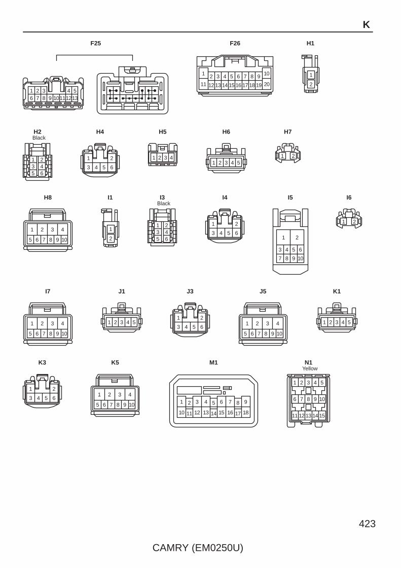
CAMRY (EM0250U)
423
K
1 2 3 4 56 7 8 9 10111213
F25
5 6 7 8 9 10
11 12 13 14
3 421
15 16 17 18 19 20
F26
1
2
H1
214365
BlackH2
1 2
3 4 5 6
H4
1 2 3 4
H5
1 2 3 4 5
H6
1 2
H7
1 2 3 4
5 6 7 8 9 10
H8
1
2
I1
214365
BlackI3
1 2
3 4 5 6
I4
1 2
3 4 5 6
7 8 9 10
I5
1 2
I6
1 2 3 4
5 6 7 8 9 10
I7
1 2 3 4 5
J1
1 2
3 4 5 6
J3
1 2 3 4
5 6 7 8 9 10
J5
1 2 3 4 5
K1
1 2
3 4 5 6
K3
1 2 3 4
5 6 7 8 9 10
K5
6 95 8
14
7
15
4
17
21
1816
3
11 1310 12
M1
43
6 7
5
11
1
12
2
15
98
1413
10
YellowN1
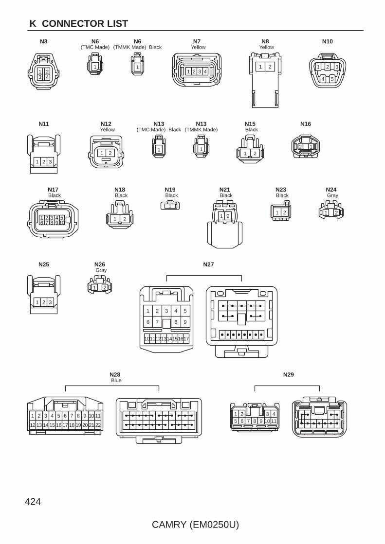
424
CAMRY (EM0250U)
K CONNECTOR LIST
1 23 4
N3
1
(TMC Made)N6
1
(TMMK Made) BlackN6
1 2 3 4
YellowN7
21
YellowN8
1 2 3
4 5
N10
1 2 3
N11
1 2
YellowN12
1
(TMC Made) BlackN13
1
(TMMK Made)N13
1 2
BlackN15
12
N16
1 2 3 4 56 7 8 9 10
BlackN17
1 2
BlackN18
1
BlackN19
21
BlackN21
1 2
BlackN23
1 2
GrayN24
1 2 3
N25
1 2
GrayN26
9
1 2 3 4 5
876
1716151413121110
N27
11
2221
109
2019
87
1817
65
1615
43
1413
1 2
12
BlueN28
1 2 3 45 6 7 8 9 10 11
N29

CAMRY (EM0250U)
425
K
1 2 3 4 5
N34
43
6 7
5
11
1
12
2
15
98
1413
10
YellowO1
1 2
O3
1 2 3 4 57 8 9 101112
6
BlackO4
1
O6
1 2 3 4
YellowO7
21
YellowO8
1 2
YellowO9
1
BlackO10
2 1
O12
2 1
O13
23 41
O14
23 41
O15
21
BlackO16
1 2 3 4 5
O17
654
3217
O18
1
GrayO19
9
1 2 3 4 5
876
1716151413121110
O20
1 2 3 45 6 7 8 9 10 11
O21
1
BlackP1
2 1
Q1
2 1
Q2
1 2 3 4 5
Q3
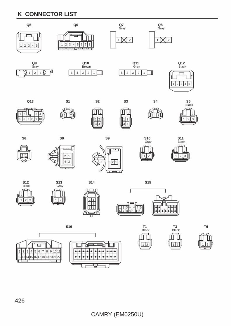
426
CAMRY (EM0250U)
K CONNECTOR LIST
1 2 3 4 5
Q5
2 3 4 5 6 7 81
Q6
1 2
GrayQ7
1 2
GrayQ8
1 2 3
GrayQ9
4 23 15
BrownQ10
4 23 15
GrayQ11
1 2 3 4 5
BlackQ12
1 2 3 4
5 6 7 8 9 10
Q13
1 2
S1
2
3 4
1
S2
2
3 4
1
S3
1 2
S4
1 32
BlackS5
12
S6
4 3
12
S8
2 1
S9
1 2
GrayS10
1 32
BlackS11
1 32
BlackS12
1 2
GrayS13
2 14 36 5
S14
543216 7 8 9 101112
S15
11
2221
109
2019
87
1817
65
1615
43
1413
1 2
12
S16
1 2
BlackT1
1 2
BlackT3
1 2
T6

CAMRY (EM0250U)
427
K
1 2
T7
1 2 3 4
5 6 7 8 9 10
BlackT8
1 2 3 4 57 8 9 101112
6
BlackT10
1 2 3 4 57 8 9 101112
6
GrayT11
1 2 3
BlackT14
1 2 3
GrayT15
1 2 3
GrayT16
1 2 3
BlackT17
9
1 2 3 4 5
876
1716151413121110
T18
1 2
BlackU1
1 2
BlackU2
1 2
BlackU3
1 2
BlackU4
1 2
U5
1 2
U6
1 2 3 4
5 6 7 8 9 10
BlackU7
1 2 3 4 5
U8
9
1 2 3 4 5
876
1716151413121110
U11
1 2
GrayV1
1 2
BlackV2
1 23 45 6
W1
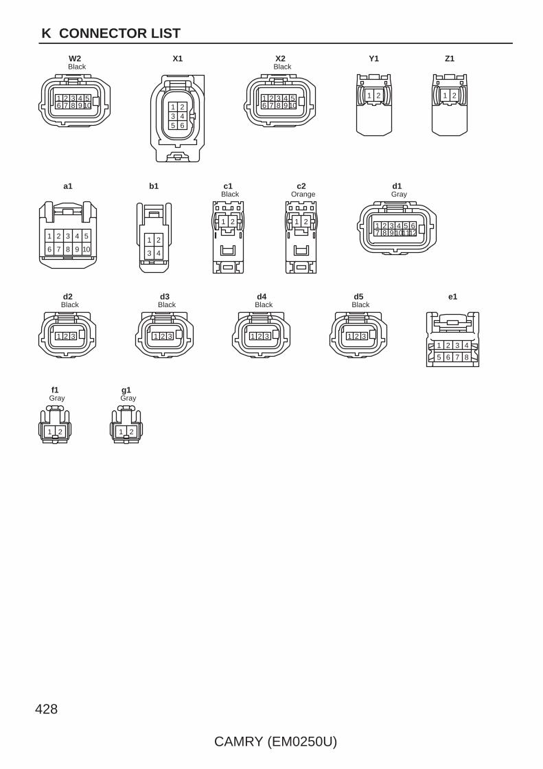
428
CAMRY (EM0250U)
K CONNECTOR LIST
1 2 3 4 56 7 8 9 10
BlackW2
1 23 45 6
X1
1 2 3 4 56 7 8 9 10
BlackX2
21
Y1
21
Z1
1 2 3 4 5
6 7 8 9 10
a1
1 2
3 4
b1
21
Blackc1
21
Orangec2
1 2 3 4 57 8 9 101112
6
Grayd1
1 2 3
Blackd2
1 2 3
Blackd3
1 2 3
Blackd4
1 2 3
Blackd5
6 7 85
2 3 41
e1
1 2
Grayf1
1 2
Grayg1

CAMRY (EM0250U)
429
Memo

430
CAMRY (EM0250U)
K CONNECTOR LIST
1 2 3
4 5
123
45 2 4 5 6 8
14 16131210
3
11
7
15
22 24212018 19 23
1 9
17 25
7 6 5 4 3
22 2123 20 19
2
18
8
24
14 1315 12 11 1016
19
1725
3 4
1
65
234
1
6 5
22 1
4 31 2
3 4
4
10
53 6 7
14 1513 16 1720
1
11 8
18
2
12
9
19
7 6 5 4 3
16 1517 14 13
110
1120 2
12
8
1819
9
2 4 5 6 8
14 16131210
3
11
7
15
22 24212018 19 23
1 9
17 25
7 6 5 4 3
22 2123 20 19
2
18
8
24
14 1315 12 11 1016
19
1725
1 2 12
AB1 Gray AE2 Gray
AE3 AE4 Yellow
AE5
AE6 Gray AE7

CAMRY (EM0250U)
431
K
1 2 12 1 2 3 4 5 6 7 8 9 10
11 1213141516171819 20
12345678910
11121314151617181920
1 23 4 5 6 78 9 10 11 12
12
34567
89101112
1 23 4
2 14 3
4
9
53 6 7
13 1412 15 16
82
18
1
171110 7 6 5 4 3
15 1416 13 12
1289
10111718
9
1 2 3 4 5
876
1716151413121110
12345
6789
1011121314151617
CV1 Gray
CA1 CA2Black
CA3
EA1
EN1

432
CAMRY (EM0250U)
K CONNECTOR LIST
4
10
53 6 7
14 1513 16 1720
1
11 8
18
2
12
9
19
7 6 5 4 3
16 1517 14 13
110
1120 2
12
8
1819
9
9
1 2 3 4 5
876
1716151413121110
12345
6789
1011121314151617
4
10
53 6 7
14 1513 16 1720
1
11 8
18
2
12
9
19
7 6 5 4 3
16 1517 14 13
110
1120 2
12
8
1819
9
4
10
53 6 7
14 1513 16 17
20
1
11 8
18
2
12
9
19
7 6 5 4 3
16 1517 14 13
110
1120 2
12
8
1819
9
1 2 3 44 3 12
EN2 Blue
EO1
EO2 Blue
EQ1 Ec1 Yellow

CAMRY (EM0250U)
433
K
4
10
53 6 7
14 1513 16 1720
1
11 8
18
2
12
9
19
7 6 5 4 3
16 1517 14 13
110
1120 2
12
8
1819
9
9
1 2 3 4 5
876
1716151413121110
12345
6789
1011121314151617
9
1 2 3 4 5
876
1716151413121110
12345
6789
1011121314151617
2 4 5 6 8
14 16131210
3
11
7
15
22 24212018 19 23
1 9
17 25
7 6 5 4 3
22 2123 20 19
2
18
8
24
14 1315 12 11 1016
19
1725
1 2 3 45 6 7 8
4 3 2 18 7 6 5
9
1 2 3 4 5
876
1716151413121110
12345
6789
1011121314151617
2 4 5 6 8
14 16131210
3
11
7
15
22 24212018 19 23
1 9
17 25
7 6 5 4 3
22 2123 20 19
2
18
8
24
14 1315 12 11 1016
19
1725
FE2 Blue
FE3 Gray HE1 Gray
HE2 HW1 Gray
IE1 Gray IE2

434
CAMRY (EM0250U)
K CONNECTOR LIST
4
9
53 6 7
13 1412 15 16
82
18
1
171110 7 6 5 4 3
15 1416 13 12
1289
10111718
1 2 3 4 56 7 8 9 10 11 12 13
12345
13 6789101112
1 2 3 45 6 7 8
4 3 2 18 7 6 5
1 23 4
5 6 78 9
10 11 12131415 16 171819 20
1234
56789
1011121314151617181920
1 23 4
5 6 78 9
10 11 12131415 16 171819 20
1234
56789
1011121314151617181920
IM1
IX1 Gray
JO1
IM2 Blue
KN1

CAMRY (EM0250U)
435
K
4
9
53 6 7
13 1412 15 16
82
18
1
171110 7 6 5 4 3
15 1416 13 12
1289
10111718
1 22 1
4
9
53 6 7
13 1412 15 16
82
18
1
171110 7 6 5 4 3
15 1416 13 12
1289
10111718
4
9
53 6 7
13 1412 15 16
82
18
1
171110 7 6 5 4 3
15 1416 13 12
1289
10111718
1 2 34 5 6
123456
1 22 1
4
9
53 6 7
13 1412 15 16
82
18
1
171110 7 6 5 4 3
15 1416 13 12
1289
10111718
1 2 12 1 2 12
NA1 Black NZ2Yellow
OA1 Black
OF1 Black OT1 Gray
OY2Yellow
SN1
fO1Gray
gN1Gray

L PART NUMBER OF CONNECTORS
Code Part Name Part Number Code Part Name Part Number
CAMRY (EM0250U)
Note: Not all of the above part numbers of the connector are established for the supply.
436
A1 Fog Lamp (Front LH) 82824–60460
A2 Ambient Temp. Sensor 90980–11070
A3 Horn (High)90980–10619
A4 Horn (Low)90980–10619
A5 Engine Hood Courtesy SW 90980–11002
A6 A/C Condenser Fan Motor90980–10928
A7 Radiator Fan Motor90980–10928
A8 Headlamp (LH High) 90980–11659
A13 Airbag Sensor (Front LH) 90980–12490
A14 Speed Sensor (Front LH) 90980–11002
A16 Brake Fluid Level Warning SW 90980–11207
A17 Accelerator Position Sensor 90980–12303
A18 Parking Brake SW 90980–10871
A19 Stop Lamp SW 90980–11118
A21 Cruise Control Clutch SW 90980–10906
A22 Clutch Start SW 90980–10825
A23 Security Horn 90980–10619
A24 Engine Control Module 90980–12461
A25 Skid Control ECU with Actuator 90980–WB001
A26 Skid Control ECU with Actuator 90980–12297
A27 A/C Pressure Sensor 90980–10845
A28 Airbag Sensor (Front RH) 90980–12490
A29 Headlamp (RH High) 90980–11659
A34 Fog Lamp (Front RH) 82824–60460
A35 Speed Sensor (Front RH) 90980–11002
A37 Windshield Washer Motor 90980–11019
A40 Junction Connector 90980–11661
A41 Junction Connector90980–12372
A42 Junction Connector90980–12372
A43 Junction Connector 90980–11194
A45 Headlamp (LH Low) 82824–60460
A46 Turn Signal and Parking Lamp (Front LH) 90980–11020
A47 Side Marker Lamp (Front LH) 90980–11162
A48 Wireless Door Lock Buzzer 90980–11142
A49 Headlamp (RH Low) 82824–60460
A50 Turn Signal and Parking Lamp (Front RH) 90980–11020
A51 Side Marker Lamp (Front RH) 90980–11162
A52 Washer Level Warning SW 90980–11068
A53 VSV (Air Intake Control) 90980–11156
A54 Cooling Fan ECU 90980–12058
A55 Engine Control Module 90980–12462
A56 Short Connector 90980–12204
A57 Short Connector 90980–12012
A58 Junction Connector 90980–11661
A59 Windshield Wiper Motor 90980–11599
A60 Skid Control ECU with Actuator 90980–WA008
B1 Windshield Wiper Motor 90980–11599
C1 Park/Neutral Position SW 90980–12362
C2 Mass Air Flow Meter 90980–12292
C3 Starter 90980–11400
C4 Engine Coolant Temp. Sensor 90980–10735
C5 Throttle Body Assembly 90980–11858
C6 VSV (Purge) 90980–11156
C7 Fuel Injector (No.1)
90980–11875C8 Fuel Injector (No.3)
90980–11875C9 Fuel Injector (No.2)
90980–11875
C10 Fuel Injector (No.4)
C11 Ignition Coil (No.1)
90980–11885C12 Ignition Coil (No.3)
90980–11885C13 Ignition Coil (No.2)
90980–11885
C14 Ignition Coil (No.4)
C15 Air Fuel Ratio Sensor (Bank 1 Sensor 1) 90980–11178
C16 Noise Filter (Ignition RH) 90980–10843
C17 Power Steering Oil Pressure SW 90980–11428
C18 Generator 90980–11964
C19Generator (2AZ–FE) 90980–09213
C19Generator (2GR–FE) 90980–09983
C20 Crankshaft Position Sensor 90980–10947
C21 A/C Compressor 90980–11156
C22 Heated Oxygen Sensor (Bank 1 Sensor 2) 90980–11028
C23 Engine Oil Pressure SW 90980–11363
C24 Engine Control Module 90980–12398
C25Electronically Controlled TransmissionSolenoid 90980–12326
C26 Transmission Revolution Sensor (Turbine)
90980–11156C27
Transmission Revolution Sensor (CounterGear)
90980–11156
C28 Back–Up Lamp SW 90980–11250
C29 Starter 90980–11400
C30 Knock Control Sensor (Bank 1) 90980–11875
C31 Camshaft Position Sensor 90980–10947
C32 Camshaft Timing Oil Control Valve 90980–11162
C33 Intake Air Control Valve 90980–11599
C34 VSV (ACM) 90980–11156
C35 Air Fuel Ratio Sensor (Bank 2 Sensor 1) 90980–11178
C36 Fuel Injector (No.5)90980–11875
C37 Fuel Injector (No.6)90980–11875
C38 Ignition Coil (No.5)90980–11885
C39 Ignition Coil (No.6)90980–11885
C40 VVT Sensor (Bank 1 Exhaust Side)90980–12353
C41 VVT Sensor (Bank 1 Intake Side)90980–12353
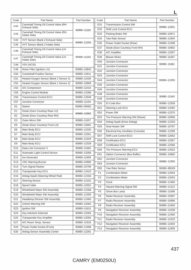
L
Code Part Name Part Number Code Part Name Part Number
CAMRY (EM0250U)
437
C42Camshaft Timing Oil Control Valve (RHExhaust Side)
90980–11162
C43Camshaft Timing Oil Control Valve (RHIntake Side)
90980–11162
C44 VVT Sensor (Bank 2 Exhaust Side)90980–12353
C45 VVT Sensor (Bank 2 Intake Side)90980–12353
C46Camshaft Timing Oil Control Valve (LHExhaust Side)
90980–11162C47
Camshaft Timing Oil Control Valve (LHIntake Side)
90980–11162
C48 VSV (ACIS)
C49 Noise Filter (Ignition LH) 90980–10843
C50 Crankshaft Position Sensor 90980–12611
C51 Heated Oxygen Sensor (Bank 2 Sensor 2) 90980–11028
C52 Heated Oxygen Sensor (Bank 1 Sensor 2) 90980–10869
C53 A/C Compressor 90980–11016
C55 Engine Control Module 90980–12396
C56 Transmission Control ECU 90980–12649
C57 Junction Connector 90980–11194
D1 Starter 90980–09463
E1 Diode (Door Courtesy Rear LH)90980–10962
E2 Diode (Door Courtesy Rear RH)90980–10962
E3 Outer Mirror SW 90980–11657
E5 Diode (Door Courtesy Front LH) 90980–10962
E6 Main Body ECU 90980–12330
E7 Main Body ECU 90980–12561
E8 Main Body ECU 90980–12329
E9 Main Body ECU 90980–12328
E10 Data Link Connector 3 90980–11665
E11 Automatic Light Control Sensor 90980–12056
E12 Ion Generator 90980–11909
E13 VSC Warning Buzzer 90980–10906
E14 Turn Signal Flasher 90980–10799
E15 Transponder Key ECU 90980–12423
E16 Airbag Squib (Steering Wheel Pad) 90980–12160
E17 Steering Sensor 90980–12162
E18 Spiral Cable 90980–12552
E19 Windshield Wiper SW Assembly 90980–12358
E20 Windshield Wiper SW Assembly 90980–12359
E21 Headlamp Dimmer SW Assembly 90980–12460
E22 Unlock Warning SW 90980–12063
E23 Ignition SW 90980–11615
E24 Key Interlock Solenoid 90980–12063
E25 Transponder Key Amplifier 90980–12092
E27 A/C Room Temp. Sensor 90980–11918
E29 Power Outlet Socket (Front) 90980–12498
E30 Airbag Sensor Assembly Center 90980–12391
E31 Transmission Control SW90980–12551
E32 Shift Lock Control ECU90980–12551
E33 Parking Brake SW 90980–10871
E34 Yaw Rate Sensor 90980–11904
E35 Power Outlet Socket (Rear) 90980–12498
E37 Diode (Door Courtesy Front RH) 90980–10962
E38 A/C Amplifier 90980–12557
E39 Blower Motor 90980–11667
E40 Junction Connector90980–11661
E41 Junction Connector90980–11661
E42 Junction Connector
90980–12355
E43 Junction Connector
90980–12355E44 Junction Connector 90980–12355
E45 Junction Connector
E46 Junction Connector
E48 Junction Connector90980–11542
E49 Junction Connector90980–11542
E50 ID Code Box 90980–12558
E51 Steering Lock ECU 90980–12092
E52 Power SW 90980–12370
E53 Tire Pressure Warning SW (Reset) 90980–10906
E54 Airbag Squib (Knee Airbag) 90980–12253
E55 Seat Heater SW 90980–10797
E56 Electrical Key Oscillator (Console) 90980–12296
E57 Shift Lock Control ECU 90980–12552
E58 Certification ECU 90980–12567
E59 Certification ECU 90980–12566
E60 Tire Pressure Warning ECU 90980–12552
E61 Option Connector (Bus Buffer) 90980–10860
E62 Junction Connector90980–12355
E63 Junction Connector90980–12355
E65 Yaw Rate Sensor 90080–98249
F1 Combination Meter 90980–12554
F2 Combination Meter 90980–12553
F3 Clock 90980–12460
F4 Hazard Warning Signal SW 90980–12113
F5 Glove Box Lamp 90980–11098
F6 Radio Receiver Assembly 90980–10997
F7 Radio Receiver Assembly 90980–10996
F8 Radio Receiver Assembly 90980–12460
F9 Navigation Receiver Assembly 90980–12038
F10 Navigation Receiver Assembly 90980–12460
F11 Radio Receiver Assembly 90980–12423
F12 Navigation Receiver Assembly 90980–12404
F13 Navigation Receiver Assembly 90980–11909
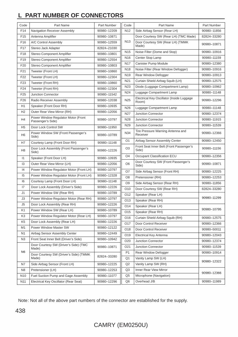
L PART NUMBER OF CONNECTORS
Code Part Name Part Number Code Part Name Part Number
CAMRY (EM0250U)
Note: Not all of the above part numbers of the connector are established for the supply.
438
F14 Navigation Receiver Assembly 90980–12209
F15 Antenna Amplifier 90980–10871
F16 A/C Control Assembly 90980–12559
F17 Stereo Jack Adapter 82824–21030
F18 Stereo Component Amplifier 90980–10801
F19 Stereo Component Amplifier 90980–12554
F20 Stereo Component Amplifier 90980–10803
F21 Tweeter (Front LH) 90980–10860
F22 Tweeter (Front LH) 90980–12304
F23 Tweeter (Front RH) 90980–10860
F24 Tweeter (Front RH) 90980–12304
F25 Junction Connector 90980–11542
F26 Radio Receiver Assembly 90980–12038
H1 Speaker (Front Door RH) 90980–10935
H2 Outer Rear View Mirror (RH) 90980–12056
H4Power Window Regulator Motor (FrontPassenger’s Side) 90980–10797
H5 Door Lock Control SW 90980–11950
H6Power Window SW (Front Passenger’sSide) 90980–10789
H7 Courtesy Lamp (Front Door RH) 90980–11148
H8Door Lock Assembly (Front Passenger’sSide) 90980–12226
I1 Speaker (Front Door LH) 90980–10935
I3 Outer Rear View Mirror (LH) 90980–12056
I4 Power Window Regulator Motor (Front LH) 90980–10797
I5 Power Window Regulator Motor (Front LH) 90980–12328
I6 Courtesy Lamp (Front Door LH) 90980–11148
I7 Door Lock Assembly (Driver’s Side) 90980–12226
J1 Power Window SW (Rear RH) 90980–10789
J3 Power Window Regulator Motor (Rear RH) 90980–10797
J5 Door Lock Assembly (Rear RH) 90980–12226
K1 Power Window SW (Rear LH) 90980–10789
K3 Power Window Regulator Motor (Rear LH) 90980–10797
K5 Door Lock Assembly (Rear LH) 90980–12226
M1 Power Window Master SW 90980–12122
N1 Airbag Sensor Assembly Center 90980–12449
N3 Front Seat Inner Belt (Driver’s Side) 90980–10942
N6
Door Courtesy SW (Driver’s Side) (TMCMade) 90980–10871
N6Door Courtesy SW (Driver’s Side) (TMMKMade) 82824–33280
N7 Side Airbag Sensor (Front LH) 90980–12225
N8 Pretensioner (LH) 90980–12253
N10 Fuel Suction Pump and Gage Assembly 90980–11077
N11 Electrical Key Oscillator (Rear Seat) 90980–12296
N12 Side Airbag Sensor (Rear LH) 90980–11856
N13
Door Courtesy SW (Rear LH) (TMC Made) 82824–33280
N13 Door Courtesy SW (Rear LH) (TMMKMade) 90980–10871
N15 Noise Filter (Dome and Stop) 90980–10916
N16 Center Stop Lamp 90980–11159
N17 Canister Pump Module 90980–12380
N18 Noise Filter (Rear Window Defogger) 90980–10916
N19 Rear Window Defogger 90980–10913
N21 Curtain Shield Airbag Squib (LH) 90980–12575
N23 Diode (Luggage Compartment Lamp) 90980–10962
N24 Luggage Compartment Lamp 90980–11148
N25Electrical Key Oscillator (Inside LuggageRoom) 90980–12296
N26 Luggage Compartment Lamp 90980–11148
N27 Junction Connector 90980–12374
N28 Junction Connector 90980–11915
N29 Junction Connector 90980–11539
N34Tire Pressure Warning Antenna andReceiver 90980–12366
O1 Airbag Sensor Assembly Center 90980–12450
O3Front Seat Inner Belt (Front Passenger’sSide) 90980–11156
O4 Occupant Classification ECU 90980–12356
O6Door Courtesy SW (Front Passenger’sSide) 90980–10871
O7 Side Airbag Sensor (Front RH) 90980–12225
O8 Pretensioner (RH) 90980–12253
O9 Side Airbag Sensor (Rear RH) 90980–11856
O10 Door Courtesy SW (Rear RH) 82824–33280
O12 Speaker (Rear LH)90980–11299
O13 Speaker (Rear RH)90980–11299
O14 Speaker (Rear LH)90980–10795
O15 Speaker (Rear RH)90980–10795
O16 Curtain Shield Airbag Squib (RH) 90980–12575
O17 Door Control Receiver 90980–12366
O18 Door Control Receiver 90980–50011
O19 Electrical Key Antenna 90980–12043
O20 Junction Connector 90980–12374
O21 Junction Connector 90980–11539
P1 Rear Window Defogger 90980–10914
Q1 Vanity Lamp SW (LH)90980–12322
Q2 Vanity Lamp SW (RH)90980–12322
Q3 Inner Rear View Mirror90980–12366
Q5 Microphone (Navigation)90980–12366
Q6 Overhead J/B 90980–11989
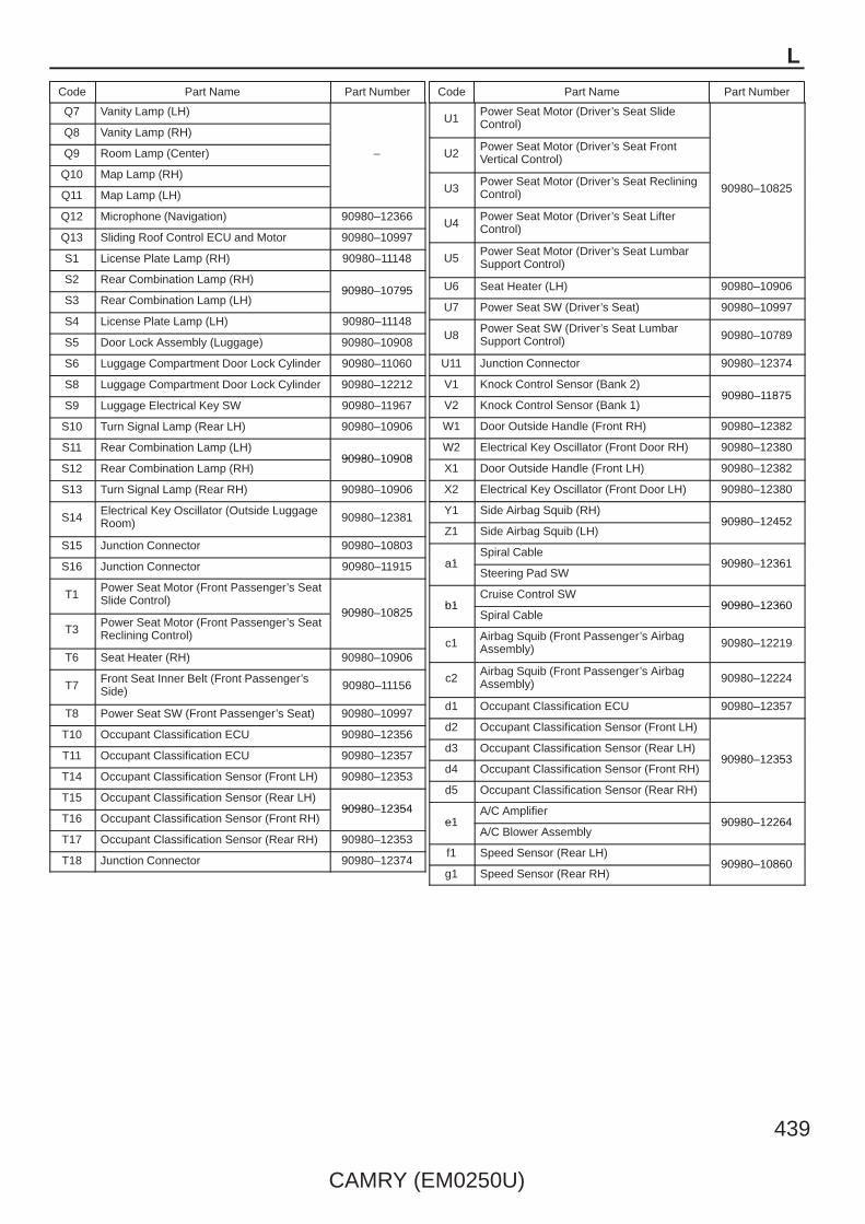
L
Code Part Name Part Number Code Part Name Part Number
CAMRY (EM0250U)
439
Q7 Vanity Lamp (LH)
–
Q8 Vanity Lamp (RH)
–Q9 Room Lamp (Center) –
Q10 Map Lamp (RH)
Q11 Map Lamp (LH)
Q12 Microphone (Navigation) 90980–12366
Q13 Sliding Roof Control ECU and Motor 90980–10997
S1 License Plate Lamp (RH) 90980–11148
S2 Rear Combination Lamp (RH)90980–10795
S3 Rear Combination Lamp (LH)90980–10795
S4 License Plate Lamp (LH) 90980–11148
S5 Door Lock Assembly (Luggage) 90980–10908
S6 Luggage Compartment Door Lock Cylinder 90980–11060
S8 Luggage Compartment Door Lock Cylinder 90980–12212
S9 Luggage Electrical Key SW 90980–11967
S10 Turn Signal Lamp (Rear LH) 90980–10906
S11 Rear Combination Lamp (LH)90980–10908
S12 Rear Combination Lamp (RH)90980–10908
S13 Turn Signal Lamp (Rear RH) 90980–10906
S14Electrical Key Oscillator (Outside LuggageRoom) 90980–12381
S15 Junction Connector 90980–10803
S16 Junction Connector 90980–11915
T1Power Seat Motor (Front Passenger’s SeatSlide Control)
90980–10825
T3Power Seat Motor (Front Passenger’s SeatReclining Control)
90980–10825
T6 Seat Heater (RH) 90980–10906
T7Front Seat Inner Belt (Front Passenger’sSide) 90980–11156
T8 Power Seat SW (Front Passenger’s Seat) 90980–10997
T10 Occupant Classification ECU 90980–12356
T11 Occupant Classification ECU 90980–12357
T14 Occupant Classification Sensor (Front LH) 90980–12353
T15 Occupant Classification Sensor (Rear LH)90980–12354
T16 Occupant Classification Sensor (Front RH)90980–12354
T17 Occupant Classification Sensor (Rear RH) 90980–12353
T18 Junction Connector 90980–12374
U1Power Seat Motor (Driver’s Seat SlideControl)
90980–10825
U2Power Seat Motor (Driver’s Seat FrontVertical Control)
90980–10825U3Power Seat Motor (Driver’s Seat RecliningControl) 90980–10825
U4Power Seat Motor (Driver’s Seat LifterControl)
U5Power Seat Motor (Driver’s Seat LumbarSupport Control)
U6 Seat Heater (LH) 90980–10906
U7 Power Seat SW (Driver’s Seat) 90980–10997
U8Power Seat SW (Driver’s Seat LumbarSupport Control) 90980–10789
U11 Junction Connector 90980–12374
V1 Knock Control Sensor (Bank 2)90980–11875
V2 Knock Control Sensor (Bank 1)90980–11875
W1 Door Outside Handle (Front RH) 90980–12382
W2 Electrical Key Oscillator (Front Door RH) 90980–12380
X1 Door Outside Handle (Front LH) 90980–12382
X2 Electrical Key Oscillator (Front Door LH) 90980–12380
Y1 Side Airbag Squib (RH)90980–12452
Z1 Side Airbag Squib (LH)90980–12452
a1Spiral Cable
90980–12361a1Steering Pad SW
90980–12361
b1Cruise Control SW
90980–12360b1Spiral Cable
90980–12360
c1Airbag Squib (Front Passenger’s AirbagAssembly) 90980–12219
c2Airbag Squib (Front Passenger’s AirbagAssembly) 90980–12224
d1 Occupant Classification ECU 90980–12357
d2 Occupant Classification Sensor (Front LH)
90980–12353d3 Occupant Classification Sensor (Rear LH)
90980–12353d4 Occupant Classification Sensor (Front RH)
90980–12353
d5 Occupant Classification Sensor (Rear RH)
e1A/C Amplifier
90980–12264e1A/C Blower Assembly
90980–12264
f1 Speed Sensor (Rear LH)90980–10860
g1 Speed Sensor (Rear RH)90980–10860

1 2 3 4
HOW TO READ THIS SECTION
4
8
1
7
2
AM2
AM1
ACC
IG1
ST1
IG2
ST2
2 2
2
100A
ALT
40A
AM
1
30A
AM
2
Battery
M
A1
B1
A1 B1
A2 B2
AB36
A1
BA37
7. 5AIGN
2
1
15AEFI
2
2 2
2
(BAT)
1 2
3 4
11
BA112
1 1
A1
1 6
2 3
AD25
AD116
M
1
2
A3
BA321
3C7
3C15
1
2
1
2
1
2
1
2
B1
3
2 3 1
48
22
1
B- R B- R B- R
W- R W- R
W- R W- R
W- R
Y- R
B
R- Y
GR
B- L
B- R
B- W
B- W
B
W
Y- R Y- R
R- YB- L
B
W
W-R
WW
-R
B-L
B-W
B-W
B-W
B-W
B-W
Y-R
Y-R
W-B
W-BW
-B
R-G
R-G
R-G
W-B
B-W
R-Y
R-Y
B-R
B-R
B-R
B-R
B-R
B-R
B-R
W-R
W-R
W-R
W-R
BR
BR
Y-R B
B
E n g in e C o n tro lS ta r tin g
W-B
( 2L-
T)
( 2L-
T)( 2
L-T)
(2L- T)
(2L- T)
(2L- T)
B-W
B-W
( 22R
-E)
( 22R
-E)
B-R
B- R B- R
Ignition SWA 6
StarterRelay
A40(A), A41(B)
EFI MAINRelay
StarterB38(A), B39(B)
Y-R
Em
issi
on E
CU
<9-
8>
BA317
R-G
R-G
R-G
1
FP E1
+B OX1
( Shi
elde
d)
Heated Oxygen SensorA11
W- R
Circ
uit O
peni
ngR
elay
A19
Dat
a Li
nk C
onne
ctor
1B
1
Inje
ctio
n N
o. 4
B12
Inje
ctio
n N
o. 3
B10
Inje
ctio
n N
o. 2
B11
Inje
ctio
n N
o. 1
B9
Fuel
Pum
pA
37
A
B
C
D
E
F
* The system shown here is an EXAMPLE ONLY. It is different to the actual circuit shown in the wiring diagram section.
[L]
[M]
[E]
[F]
[D]
[J]
[G]
[K]
[I]
[H][C]
[A]
[B]
M O
VE
RA
LL
EL
EC
TR
ICA
L W
IRIN
G D
IAG
RA
M
440
CA
MR
Y (E
M0250U
)
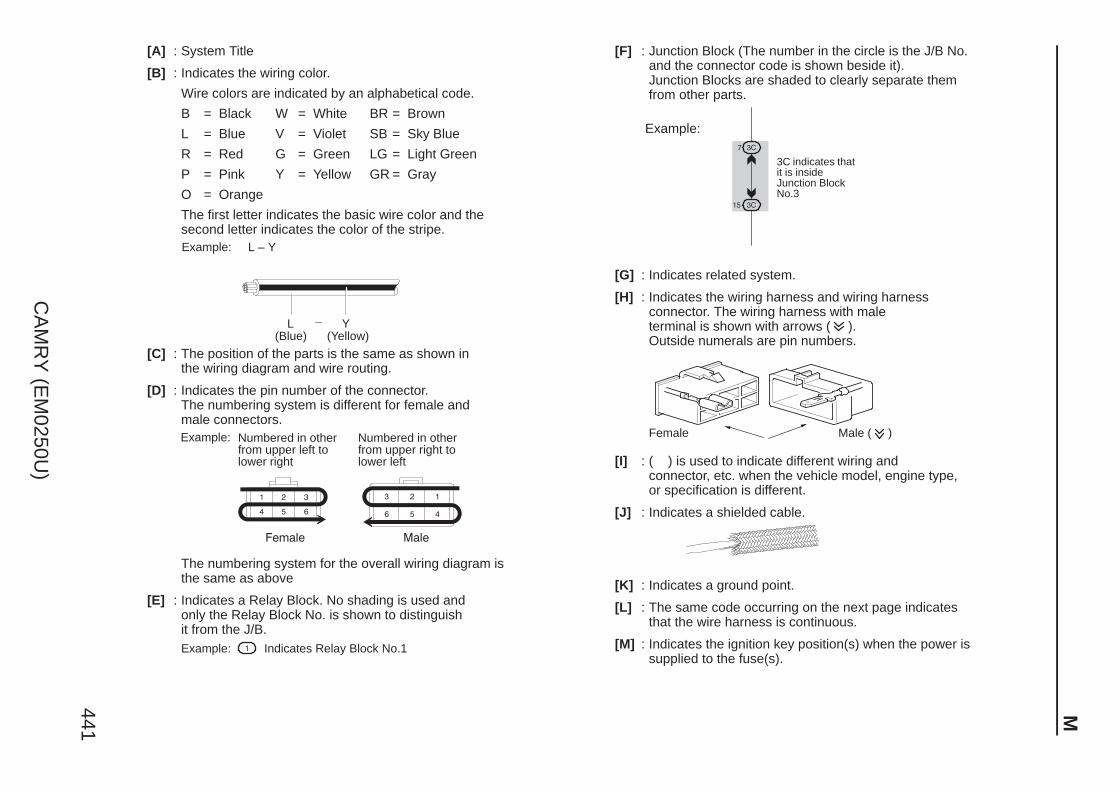
M441
CA
MR
Y (E
M0250U
)
[A] : System Title
[B] : Indicates the wiring color.
Wire colors are indicated by an alphabetical code.
B = Black W = White BR = Brown
L = Blue V = Violet SB = Sky Blue
R = Red G = Green LG = Light Green
P = Pink Y = Yellow GR = Gray
O = Orange
The first letter indicates the basic wire color and thesecond letter indicates the color of the stripe.Example: L – Y
L(Blue)
Y(Yellow)
[C] : The position of the parts is the same as shown inthe wiring diagram and wire routing.
[D] : Indicates the pin number of the connector.The numbering system is different for female and male connectors.Example: Numbered in other
from upper left tolower right
Numbered in otherfrom upper right tolower left
The numbering system for the overall wiring diagram is the same as above
[E] : Indicates a Relay Block. No shading is used and only the Relay Block No. is shown to distinguishit from the J/B.Example: Indicates Relay Block No.1
[F] : Junction Block (The number in the circle is the J/B No. and the connector code is shown beside it). Junction Blocks are shaded to clearly separate them from other parts.
3C indicates thatit is insideJunction BlockNo.3
Example:
[G] : Indicates related system.
[H] : Indicates the wiring harness and wiring harnessconnector. The wiring harness with maleterminal is shown with arrows ( ).Outside numerals are pin numbers.
Female Male ( )
[I] : ( ) is used to indicate different wiring andconnector, etc. when the vehicle model, engine type, or specification is different.
[J] : Indicates a shielded cable.
[K] : Indicates a ground point.
[L] : The same code occurring on the next page indicates that the wire harness is continuous.
[M] : Indicates the ignition key position(s) when the power is supplied to the fuse(s).

SYSTEM INDEXM
OV
ER
AL
L E
LE
CT
RIC
AL
WIR
ING
DIA
GR
AM
442
CA
MR
Y (E
M0250U
)
SYSTEMS LOCATION SYSTEMS LOCATIONABS (w/ VSC TMC Made) 12–1. . . . . . . . . . . . . . . . . . . . . . . . . . . . . . . . . . . ABS (w/ VSC TMMK Made) 13–1. . . . . . . . . . . . . . . . . . . . . . . . . . . . . . . . . . ABS (w/o VSC) 14–1. . . . . . . . . . . . . . . . . . . . . . . . . . . . . . . . . . . . . . . . . . . . Air Conditioning 27–1. . . . . . . . . . . . . . . . . . . . . . . . . . . . . . . . . . . . . . . . . . . . Audio System (6 Speaker) 24–1. . . . . . . . . . . . . . . . . . . . . . . . . . . . . . . . . . . Audio System (8 Speaker w/ Navigation System) 22–1. . . . . . . . . . . . . . . Audio System (8 Speaker w/o Navigation System) 23–1. . . . . . . . . . . . . . Automatic Glare–Resistant EC Mirror 17–4. . . . . . . . . . . . . . . . . . . . . . . . . Back–Up Light 10–1. . . . . . . . . . . . . . . . . . . . . . . . . . . . . . . . . . . . . . . . . . . . . Charging 4–3. . . . . . . . . . . . . . . . . . . . . . . . . . . . . . . . . . . . . . . . . . . . . . . . . . . Clock 17–1. . . . . . . . . . . . . . . . . . . . . . . . . . . . . . . . . . . . . . . . . . . . . . . . . . . . . Combination Meter 25–1. . . . . . . . . . . . . . . . . . . . . . . . . . . . . . . . . . . . . . . . . Cooling Fan (2GR–FE) 26–1. . . . . . . . . . . . . . . . . . . . . . . . . . . . . . . . . . . . . . Cruise Control (2AZ–FE) 8–13. . . . . . . . . . . . . . . . . . . . . . . . . . . . . . . . . . . . Cruise Control (2GR–FE) 2–18. . . . . . . . . . . . . . . . . . . . . . . . . . . . . . . . . . . . Data Link Connector 3 9–1. . . . . . . . . . . . . . . . . . . . . . . . . . . . . . . . . . . . . . . Electronically Controlled Transmission and A/T Indicator (2AZ–FE) 8–14. . . . . . . . . . . . . . . . . . . . . . . . . . . . . . . . . . . . . . . . . . . . . . . . . Electronically Controlled Transmission and A/T Indicator (2GR–FE) 2–19. . . . . . . . . . . . . . . . . . . . . . . . . . . . . . . . . . . . . . . . . . . . . . . . . Engine Control (2AZ–FE) 8–1. . . . . . . . . . . . . . . . . . . . . . . . . . . . . . . . . . . . . Engine Control (2GR–FE) 7–1. . . . . . . . . . . . . . . . . . . . . . . . . . . . . . . . . . . . Engine Immobiliser System (w/o Smart Key System) 9–3. . . . . . . . . . . . . Horn 21–2. . . . . . . . . . . . . . . . . . . . . . . . . . . . . . . . . . . . . . . . . . . . . . . . . . . . . . Ignition (2AZ–FE) 6–1. . . . . . . . . . . . . . . . . . . . . . . . . . . . . . . . . . . . . . . . . . . Ignition (2GR–FE) 5–1. . . . . . . . . . . . . . . . . . . . . . . . . . . . . . . . . . . . . . . . . . . Mirror Heater 18–3. . . . . . . . . . . . . . . . . . . . . . . . . . . . . . . . . . . . . . . . . . . . . . Multiplex Communication System (CAN) 2–1. . . . . . . . . . . . . . . . . . . . . . .
∗ Automatic Light Control∗ Door Lock Control∗ Fog Light∗ Garage Door Opener∗ Headlight∗ Illumination∗ Interior Light
∗ Key Reminder∗ Light Auto Turn Off System∗ Luggage Compartment Door Opener∗ Power Window∗ Seat Belt Warning∗ Taillight∗ Theft Deterrent∗ Wireless Door Lock Control (w/o Smart Key System)
Navigation System 22–1. . . . . . . . . . . . . . . . . . . . . . . . . . . . . . . . . . . . . . . . . Power Outlet 21–1. . . . . . . . . . . . . . . . . . . . . . . . . . . . . . . . . . . . . . . . . . . . . . . Power Seat (Driver’s Seat) 20–1. . . . . . . . . . . . . . . . . . . . . . . . . . . . . . . . . . Power Seat (Front Passenger’s Seat) 20–3. . . . . . . . . . . . . . . . . . . . . . . . . Power Source 1–1. . . . . . . . . . . . . . . . . . . . . . . . . . . . . . . . . . . . . . . . . . . . . . . Radiator Fan and Condenser Fan (2AZ–FE) 26–3. . . . . . . . . . . . . . . . . . . Rear Window Defogger 18–3. . . . . . . . . . . . . . . . . . . . . . . . . . . . . . . . . . . . . Remote Control Mirror 18–1. . . . . . . . . . . . . . . . . . . . . . . . . . . . . . . . . . . . . . Seat Heater 19–3. . . . . . . . . . . . . . . . . . . . . . . . . . . . . . . . . . . . . . . . . . . . . . . Shift Lock 21–4. . . . . . . . . . . . . . . . . . . . . . . . . . . . . . . . . . . . . . . . . . . . . . . . . Sliding Roof 17–2. . . . . . . . . . . . . . . . . . . . . . . . . . . . . . . . . . . . . . . . . . . . . . . Smart Key System 3–1. . . . . . . . . . . . . . . . . . . . . . . . . . . . . . . . . . . . . . . . . . .
∗ Engine Immobiliser∗ Push Button Start System∗ Steering Lock∗ Wireless Door Lock Control
SRS 15–1. . . . . . . . . . . . . . . . . . . . . . . . . . . . . . . . . . . . . . . . . . . . . . . . . . . . . . Starting (w/o Smart Key System) 4–1. . . . . . . . . . . . . . . . . . . . . . . . . . . . . . Stop Light 10–3. . . . . . . . . . . . . . . . . . . . . . . . . . . . . . . . . . . . . . . . . . . . . . . . . Tire Pressure Warning System 16–1. . . . . . . . . . . . . . . . . . . . . . . . . . . . . . . TRAC (TMC Made) 12–1. . . . . . . . . . . . . . . . . . . . . . . . . . . . . . . . . . . . . . . . . TRAC (TMMK Made) 13–1. . . . . . . . . . . . . . . . . . . . . . . . . . . . . . . . . . . . . . . Turn Signal and Hazard Warning Light 11–1. . . . . . . . . . . . . . . . . . . . . . . . VSC (TMC Made) 12–1. . . . . . . . . . . . . . . . . . . . . . . . . . . . . . . . . . . . . . . . . . VSC (TMMK Made) 13–1. . . . . . . . . . . . . . . . . . . . . . . . . . . . . . . . . . . . . . . . . Wiper and Washer 19–1. . . . . . . . . . . . . . . . . . . . . . . . . . . . . . . . . . . . . . . . . .

CA
MR
Y (E
M0250U
)444
M O
VE
RA
LL
EL
EC
TR
ICA
L W
IRIN
G D
IAG
RA
M
1 2 3 4
1 CAMRY (Cont. next page)
P o w e r S o u rc e
Battery
FL MAIN3. 0W
30A ABS No. 2 50A RR DEF
50A HTR
40A RDI FAN
40A CDS FAN
50A ABS No. 1
50A FAN MAIN
1G1
1
1
1 1F1
1
1
1
1
120A ALT
1 2 1 2
10A DOME
1 2
10A ECU–B NO. 1
1 2
15A RADIO NO. 1
1
1
1
1 2
15A HAZ
1 2
10A ETCS
1 2
7. 5A ALT–S
1
1
1
15A H–LP (LH)
15A H–LP (RH)
1 2
30A EFI MAIN
10A MPX–B
10A EFI NO. 1
20A A/F
7. 5A S–HORN
15A H–LP (LL)
15A H–LP (RL)
1
10A HORN
1E6
1E12 1 2
15A EFI NO. 2
1 2
10A EFI NO. 3
1 2
20A IG2
1 2
7. 5A AM2
30A ST/AM2
1 2
25A DOOR NO. 1
1
1
1
1
1
1
1
W
G
5
1
3
2
4
1 1
1
11
IB2 10A MIR HTR
B
L
W
B
B
G
W
G
LG
O
L
R
LG
W
Y Y R
GR
Y
Y
B
B
B
C19(A), (C)
(∗1)
Y
V
W–B
W
G
RR DEF Relay
Y
(∗2)
(∗2)
SHORT
W
EFI Relay
(∗3)
(∗4)
(∗3)
(∗1)
HORN Relay
H–LP (LL) Relay
H–LP (RL) RelayS–HORN Relay
A/F Relay
DRL Relay
B
∗ 4 : w/o Smart Key System∗ 3 : w/ Smart Key System∗ 2 : 2AZ–FE∗ 1 : 2GR–FE
Generator
21
25A AMP
1BR
11 2
20A STR LOCK
B1C1
(∗2)C1(∗1)A1
A
B
C
D

CA
MR
Y (E
M0250U
)445 M
7 865
1 CAMRY (Cont' d)
P o w e r S o u rc e
4
5
2
1
6AM2
AM1
ACC
IG1
ST1
IG2
ST2
E23
7. 5A RADIO NO. 2
7. 5A ECU–ACC
20A PWR OUTLET
10A GAUGE NO. 1
10A ECU IG NO. 1
25A WIP
10A WASH
10A A/C NO. 2
20A S–HTR
7. 5A ECU IG NO. 2
15A TAIL
7. 5A PANEL
25A RR DOOR LH
25A RR DOOR RH
25A PWR
30A S/ROOF
7. 5A A/C
10A STOP
5
2
3
1
1 2
30A POWER
25A DOOR NO. 2
7. 5A AM1
5
2
3
1
1 2
30A P/SEAT
5
1
3
2
4
5
2
3
1
15A FR FOG
7. 5A OBD
IF10
IA1
II3
II4
II9
II7 7. 5A GAUGE NO. 2
10A IGN
15A INJ
1AE7
EA17 12
4M124E
4G12
1
5
2
3
1
1
1
1
E2
2
104M
104EEA1
16
64E
64G
74E
74G
4E4
4H5
E1
IG10 IM3
4E5
Y
Y
B
L
LG LG
L
L
O
B B
B
W
O
P
W–B
Y
(∗4)
(∗3)
(∗1)
B
ACC Relay
TAIL Relay
PWR Relay
IG2 Relay
(∗4) (∗4)
P(∗4)
W(∗4)
Y
O
(∗4)
(∗4)
(∗4)
(∗4)
W
P
( ∗3)
( ∗3)
B6
A1
A11
B22
B3
B17
B16
ACCD
IG1D
SSW1
SSW2
AM1
AM2
IG2D
W
P
L
V
(∗3)
(∗3)
(∗3)
(∗3)(∗1 ∗3)
(∗3)
(∗3)
(∗3)
(∗1 ∗3)
E6(A), E7(B)
(∗1 ∗3)
O
(∗1 ∗3)
(∗1)
Y
(∗1 ∗4)
BEA110
(∗1 ∗4)
Y
Y
( ∗1
∗4)
W–B
W–B
W–B
W–B
W–B
W–B
L
V
( ∗3)
( ∗3)
( ∗3)
( ∗3)
5 4
2 7
E52
(∗3)
(∗3)
BR
E49
10
BR
(∗1)EA118
(∗1)
BR
(∗1)
BR
(∗2)
(∗2)
∗ 4 : w/o Smart Key System∗ 3 : w/ Smart Key System∗ 2 : 2AZ–FE∗ 1 : 2GR–FE
IG1 Relay
Ignition SW
JunctionConnector
Pow
er S
W
Main Body ECU
SS1
Free
FullTraveling
SS2 GND
SS2 SS1
GND COM
(∗1)
A
B
C
D

CA
MR
Y (E
M0250U
)446
M O
VE
RA
LL
EL
EC
TR
ICA
L W
IRIN
G D
IAG
RA
M
M u ltip le x C o m m u n ic a tio n S y s te m (C A N )
3 421
(Cont. next page)2 CAMRY
B1 B7 B10B4B2 B8
A2 A8 A1 A7
21
26 15
A41 A49
B2 B1
76
CAN–CAN+
CAN–CAN+
CANLCANH
CANLCANHCANLCANH
CANH CANL CAN+ CAN–
B W
W
( w/o
VS
C)
B
( w/o
VS
C)
B
( w/ V
SC
)
W
( w/ V
SC
)
B W
B
( 2G
R–F
E)
Y
( 2G
R–F
E)
B W
A25 A26(A), A60(B)
C56
E38(A)E61
A40(A), E41(B)
A2 A1 1 EE2 2 G G1
D2 D1 H2 H1 B2 B1
W
B
CANL
W
E34(A), E65(B)
CANH
B B
CANH
E10
614
W
CANL
CANL CANH
E30(A)
W B W
E17
9 10
CANHCANL
B
B
CANL CANH
F1(A)
WW B
E42
( A) ,
E43
( B) ,
E44
( C) ,
E45
( D) ,
E46
( E) ,
E62
( G) ,
E63
( H)
C2C1
B W
W
B
A11 A12
B35A11
(∗2)B14(∗1)A25
A22 A13 A18 A17
Skid Control ECUwith Actuator
Skid Control ECUwith Actuator
Junction Connector
Transmission Control ECU
Data Link Connector 3
Steering SensorAirbag SensorAssembly Center
Yaw Rate SensorA/C Amplifier
Junc
tion
Con
nect
or
Option Connector(Bus Buffer)
Combination Meter
CANH CANL
49 A41 A
B W
( 2A
Z–FE
)
( 2A
Z–FE
)
( 2G
R–F
E)
( 2G
R–F
E)
Eng
ine
Con
trol M
odul
eA
55( A
) , C
55( B
)
Eng
ine
Con
trol M
odul
eA
24( A
)
A2B3
(∗1)A3(∗2)B2
∗ 2 : TMMK Made∗ 1 : TMC Made
FE314 FE313
A
B
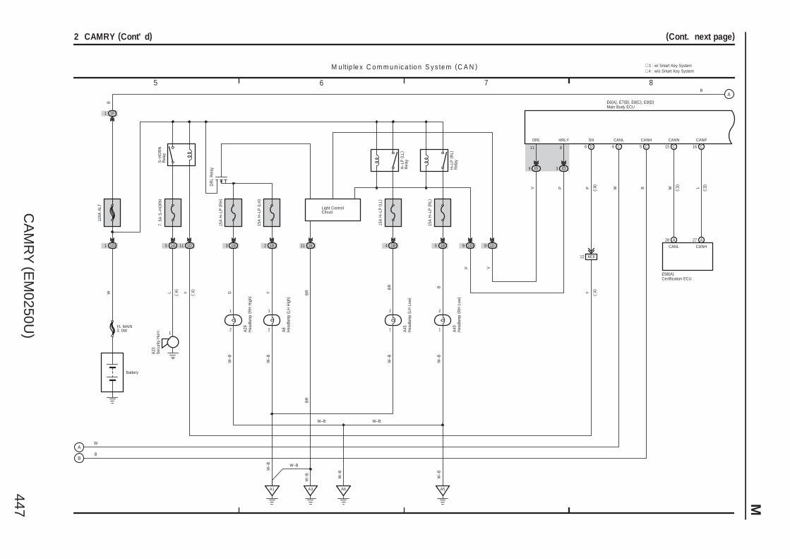
CA
MR
Y (E
M0250U
)447 M
Battery
5 1A
S–H
OR
NR
elay
1G1
120A
ALT
W
1
L
A23
7. 5
A S
–HO
RN
1F1
FL MAIN3. 0W
B
3 1B
DR
L R
elay
GW
–B
15A
H–L
P (
RH
)
B
M u ltip le x C o m m u n ic a tio n S y s te m (C A N )
15A
H–L
P (
LL)
1B 1B
15A
H–L
P (
RL)
BBR
A1 A6
W–B
W–B
5 6 7 8
(Cont. next page)2 CAMRY (Cont' d)
2
1
1
2
1
2
1D11
A5
1E11
A3
Light ControlCircuit
H–L
P (
LL)
Rel
ay
H–L
P (
RL)
Rel
ay
W–B
BR
BR
W–B
W–B
W
B
W–B W–B
W–B
W–B
1D9 1D8
P V
54
ID9 ID3
V P
11 8
DRL HRLY
D6 C6 C5
AE612
SH CANL CANH
P W B
YY
2 1B
YW
–B
15A
H–L
P (
LH)
2
1
LW
CANPCANN
16 C15 C
A28 A27
E58(A)
CANL CANH
( ∗3)
( ∗3)
E6(A), E7(B), E8(C), E9(D)
∗ 4 : w/o Smart Key System
Sec
urity
Hor
n
Certification ECU
Main Body ECU
Hea
dlam
p ( R
H H
igh)
A29
Hea
dlam
p ( L
H H
igh)
A8
Hea
dlam
p ( L
H L
ow)
A45
Hea
dlam
p ( R
H L
ow)
A49
( ∗4)
( ∗4)
( ∗4)
( ∗4)
∗ 3 : w/ Smart Key System
A
B
A
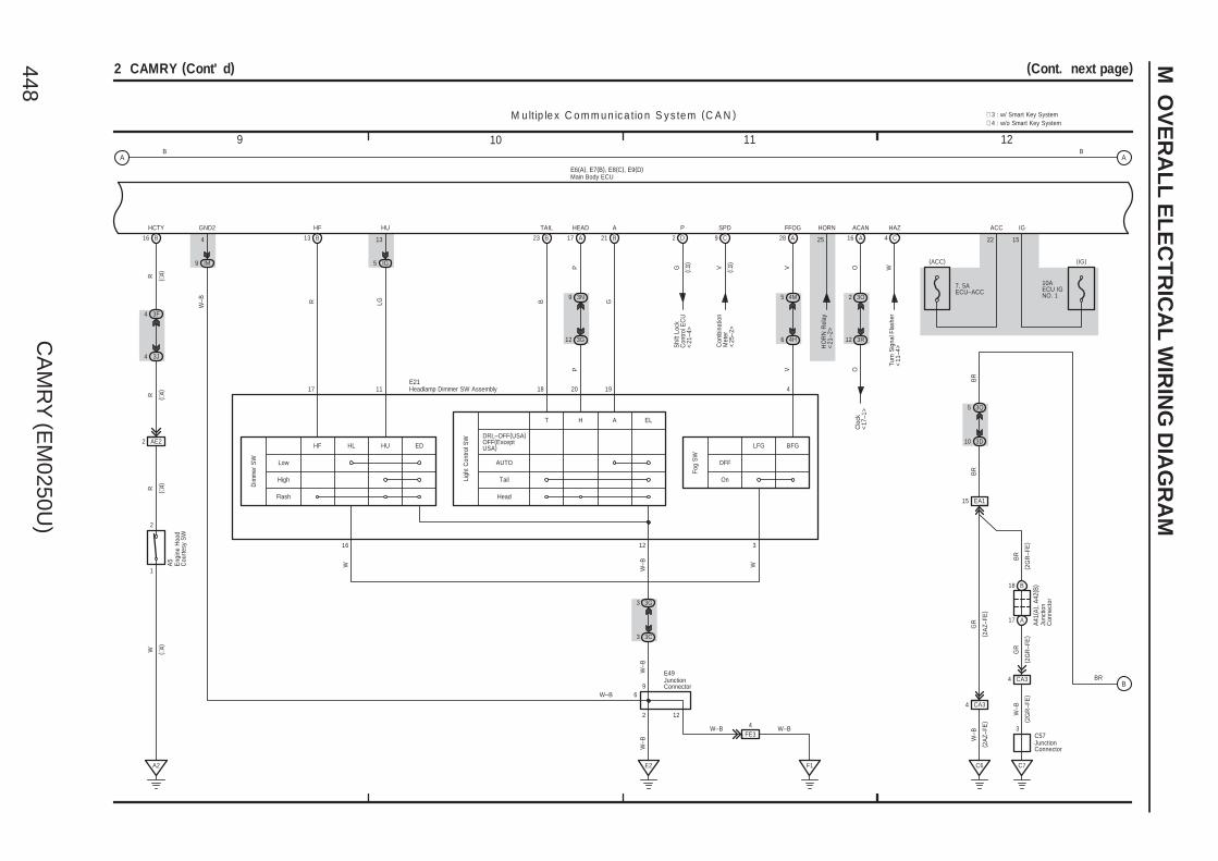
CA
MR
Y (E
M0250U
)448
M O
VE
RA
LL
EL
EC
TR
ICA
L W
IRIN
G D
IAG
RA
M
B B
M u ltip le x C o m m u n ic a tio n S y s te m (C A N )
O
ACAN
A
3O2
HAZ
C
W
3R12
OC
lock
<17
–1>
Turn
Sig
nal F
lash
er<
11–4
>
16 4
9 121110
(Cont. next page)2 CAMRY (Cont' d)
B16
3F4
3J4
AE22
1
2
A2
HCTY
RR
RW
E6(A), E7(B), E8(C), E9(D)
B23 B21B13 A28
4M5
4H6
3N9
3G12
IG5
A17
VV
R LG G
P
B
P
FFOGHF HU AHEADTAIL
IM9
E2
3G3
3C3
FE34
F1
122
9
W–B W–B
W–B
W–B
W–B
W–B
4
GND2
( 2A
Z–FE
) ( 2G
R–F
E)
( 2G
R–F
E)
A41
( A) ,
A42
( B)
GR
W–B
W–B
3
C7
4 CA3
17 A
18 B
C6
4 CA3
10 3D
5 3Q
EA115
GR
( 2A
Z–FE
)
BR
BR
( 2G
R–F
E)
C57
BR
ACC
22
IG
15
10AECU IGNO. 1
7. 5AECU–ACC
(ACC) (IG)
25
HORN
HO
RN
Rel
ay<
21–2
>
∗ 4 : w/o Smart Key System
( ∗4)
( ∗4)
( ∗4)
( ∗4)
316 12
WW
417 11 192018
SPD
C
VC
ombi
natio
nM
eter
<25
–2>
9
( ∗3)
( ∗3)
P
G
D
Shi
ft Lo
ckC
ontro
l EC
U<
21–4
>
2
BR
∗ 3 : w/ Smart Key System
Junc
tion
Con
nect
or
JunctionConnector
Main Body ECUE
ngin
e H
ood
Cou
rtesy
SW
A5
13
Low
High
Flash
HF HL HU
Dim
mer
SW
AUTO
Tail
Head
T H A
Ligh
t Con
trol S
W
ED
OFF
On
LFG BFG
Fog
SW
DRL–OFF(USA)OFF(ExceptUSA)
EL
Headlamp Dimmer SW AssemblyE21
W–B
JunctionConnector
E49
6
A A
B

CA
MR
Y (E
M0250U
)449 M
B B
M u ltip le x C o m m u n ic a tio n S y s te m (C A N )
E6(A), E7(B), E8(C), E9(D)
13 161514
(Cont. next page)2 CAMRY (Cont' d)
3R9
GR
GR
3Q10
3R10
P
G
DRIVE IC
IG2+B(DOME)IG2
MICRO COMPUTER
B2 B+B(DOME)IG2
+B(DOME)IG2
Bea
m
Tail
( Exc
ept U
SA
)H
ead
( US
A)
Fron
t Fog
Mas
ter
War
ning
DO
OR
Driv
er'
sS
eat B
elt
17 A A
MULTI LCD
18
Buzzer
A24
1
V
IG+
A
1 3D
12 3Q
1A
10AMPX–B
(BAT)
2
R
R
LG
A
12 3L
1 3Q
13 ID
7 IF
1
10ADOME
(BAT)
2
Power SupplyCircuit
13
GR
GR
A
2 3G
9 3Q
12 IG
7. 5AGAUGENO. 2
(IG)
12 A
LCD
Illum
inat
ion
Poi
nter
Illum
inat
ion
Illum
inat
ion
EA12
V
V
SB
3Q7
3U2
F1
W–B
W–BB
R
Mul
tiple
xC
omm
unic
atio
nS
yste
m (
CA
N) <
2–3>
<2–
4>
E2ES CANH CANL
+B(DOME)
+B(DOME)
F1(A)
P/SB
A9
A11
ILL–
BR
BR
BR
Main Body ECU
Combination Meter
G
3
CANI/F
RheostatTail Cancel SW
A
B
A
B
C
D

CA
MR
Y (E
M0250U
)450
M O
VE
RA
LL
EL
EC
TR
ICA
L W
IRIN
G D
IAG
RA
M
B
M u ltip le x C o m m u n ic a tio n S y s te m (C A N )
E6(A), E7(B), E8(C), E9(D)
B
3A2
2
1
3J5
3A7
LL
W–B
Unl
ock
Lock
1
2 9
Unl
ock
Lock
3
4 2
M1
H5
E22
IK15 IK12 IJ3 IJ4
L1 UL1
9 12
IE215 IE27 HE215 HE27
IE217 HE217
D
KSW
3 3C
F1
12
139
5
V G L G
V G
W–B
W–B
W–B
W–B
W–B
W–B
W–B
3B7
BTr
ansp
onde
r K
ey E
CU
<9–
3>
E2
5
17 201918
(Cont. next page)2 CAMRY (Cont' d)
GR
TSW
2 A
IND
D
YY
3K6
3R11
R
3B6
PTr
ansp
onde
rK
ey E
CU
<9–
4>
4
PRG
A
EO113
PRG RDA
RDA
A
EO114
15 EO1
3 2
15
GND+B
R L
P O
W W–B
10AECU–BNO. 1
2
1
ID10 IF1
3L9
3E9
W
26
BECU (∗4)
WO
(BAT)
W–B
O17
W–B
10 12
O1
O215
S1
9
13R8
3U2
4FE3
3N2
3D2
3N4
3E1
3F2
3N3
EN28
SN14
V G
L G
W–B
RR
OP
R
2
W–BW–B W–B
W–B
GND1
8310
19
G
GRG
W–B
PBEW IG LP
F3
W–B
W–B
∗ 3 : w/ Smart Key System∗ 4 : w/o Smart Key System∗ 5 : w/ Jam Protection∗ 6 : w/o Jam Protection
W–B 1110
( ∗4)
D7
BZR
Buz
zer
A3
B17
B16
OO
B B
W–B
W–B
( 2A
Z–FE
)
( 2G
R–F
E ∗
4)( 2
GR
–FE
∗4)
( 2A
Z–FE
)A
42( B
)
A48
2
1
( ∗4)
( ∗4)
(∗4)B2(∗3)A1
(∗3)A3(∗4)B1
( ∗4)
( ∗4)
( ∗4)
( ∗4)
( ∗4)
(∗6)(∗5)
13 IM218 IM1
13 IM13 IM2 (∗6)
(∗5)14 IM18 IM2
BR
S15 E49
W–BW–BW–BW–B
BR
Junc
tion
Con
nect
or
Wire
less
Doo
rLo
ck B
uzze
r
Unl
ock
War
ning
SW
Junction Connector
Main Body ECU
Clo
ck
Doo
r Lo
ckC
ontro
l SW
Pow
er W
indo
wM
aste
r S
W
Doo
r C
ontro
lR
ecei
ver
JunctionConnector
Junc
tion
Con
nect
or
Cer
tific
atio
n E
CU
<3–
12>
Y
5 3D
Security Indicator
Front PassengerSeat Belt Warning Light
( ∗4)
( ∗4)
( ∗4)
( ∗4)
( ∗4)
( ∗4)
( ∗4)
( ∗4)
( ∗4)
( ∗4)
( ∗4)
Lugg
age
Com
partm
ent
Doo
r Lo
ck C
ylin
der
S6(
B) ,
S8(
A)
W–B
( ∗4)
( ∗3)
AE25
A
B
C
D
A
BC
DE
F

CA
MR
Y (E
M0250U
)451 M
B
M u ltip le x C o m m u n ic a tio n S y s te m (C A N )
B
E6(A), E7(B), E8(C), E9(D)
Key
Loc
k
Key
Unl
ock
910
7
8
IE216IE224 IE29
1
4
IK16 IK2
L2
10
ACT+
1
RL BR
BR W
I7
Key
Loc
k
Key
Unl
ock
5 6
8
7
HE28 HE216 HE29
1
4
IJ1IJ5
9
6
KN13KN11
1
4
KN110
IP6 IP11
9
6
JO13JO11
1
4
JO110
IF18 IF5
LSWP
27 A
EO18 EO14 EO116
KN14 JO14
LLG GR W B L GR B L GR
LB GR
B L
W
G W
LG GR L
W–B
W–B
ACT–
3
H8
K5
J5
W–B
W–B
21 242322
(Cont. next page)2 CAMRY (Cont' d)
IE225 HE225
N1
N292
O1
O218
W–B
IJ2
LG
24
IE28
7 IK
UL2
GR
GR
LSWD
9 B
GRWG
WW–B LG
GR
LG
7 IO
N13
( A) ,
( B)
17
LCTY
IL6
1
2
LGL
( ∗7)
( ∗7)
W–BW–BW–BW–B
LL
3G9
3I9
B10
UL3
GR
B5
ACTD
GR
HE17
3O5
3I5
IP5
LSR (∗4)LSWL (∗3)
20
GR
IL5
GR
( ∗4)
3O4
3D4
LSWR
5 A
VLG
GR
(∗3)
( ∗3)
BR
L(∗7)
W–BW–BW–BBR
LG
Main Body ECU
Doo
r Lo
ck A
ssem
bly
( Fro
nt P
asse
nger
's
Sid
e)
Doo
r Lo
ck A
ssem
bly
( Driv
er'
s S
ide)
Doo
r Lo
ck A
ssem
bly
( Rea
r R
H)
Doo
r Lo
ck A
ssem
bly
( Rea
r LH
)
Doo
r C
ourte
sy S
W( R
ear
LH)
JunctionConnector
JunctionConnector
Dio
de (
Doo
rC
ourte
sy R
ear
LH)
E1
GR
LG
W L
∗ 7 : w/ Sliding Roof∗ 4 : w/o Smart Key System∗ 3 : w/ Smart Key System
(∗2)B1(∗1)A1
∗ 2 : TMMK Made∗ 1 : TMC Made
M M M M
A
BC
DE
F
A
B
CD
EF

CA
MR
Y (E
M0250U
)452
M O
VE
RA
LL
EL
EC
TR
ICA
L W
IRIN
G D
IAG
RA
M
B B
M u ltip le x C o m m u n ic a tio n S y s te m (C A N )
W
A
E11(A), (B)
CLTS
G
A
CLTS
CLTE
BR
A
CLTE
CLTB
B
A
CLTB
W–B
S5
B
S1
B
B
TR+
5 EN1
1
2
M
EN217
3
W
LGCY
E6(A), E7(B), E8(C), E9(D)
20 18 19 25 1
1
2
Q2
EQ116
18 EQ1
IR5 II10
BR
10ADOME
2
1
W
LG
W–B
(BAT)
ILE
21
25 282726
(Cont. next page)2 CAMRY (Cont' d)
L(∗7)
W–BW–BW–B
GR
YL
RCTY
A
PCTY
B
DCTY
L
6 3N
7 3C
GR
O10
1
6 EO2
Y
O6
1
5 EO2
L
N6(
A) ,
( B)
13 EN2
L
7 3I
24 21
3F113O12
3F10
1
2
3I43C6
1
2
1
2
GR
GR Y Y
B O O
E2
E5
E37
( ∗7)
( ∗7)
3N5
SN13 SN116
W B
W
14
1513
1
2
9
1
W–B
N28
S15
N23
WB
E
+B
E
Q1
2
1
B
LG
W–B
W–B
L(∗7)B(∗7)
OO
B
W
W
W
WW
BR(∗4)
W W
W(∗8)
W ( ∗8)
∗10 : Manual A/C
3A12
YTr
ansp
onde
rK
ey E
CU
<9–
4>
(∗3)A7(∗4)A5
B3A6
B6A3
(∗10)B4(∗9)A5
(∗7)
( ∗7)
( ∗7)
(∗7)
( ∗7)
BR
BR
∗ 9 : Automatic A/C∗ 8 : w/o Sliding Roof
∗ 4 : w/o Smart Key System∗ 3 : w/ Smart Key System∗ 2 : TMMK Made
(∗7)
Automatic LightControl Sensor
Dio
de (
Doo
rC
ourte
sy R
ear
RH
)
Dio
de (
Doo
rC
ourte
sy F
ront
RH
)
Dio
de (
Doo
rC
ourte
sy F
ront
LH
)
Main Body ECU
Dio
de (
Lugg
age
Com
partm
ent L
amp)
Junc
tion
Con
nect
or
Doo
r C
ourte
sy S
W( D
river
's
Sid
e)
Doo
r C
ourte
sy S
W( R
ear
RH
)
Doo
r C
ourte
sy S
W( F
ront
Pas
seng
er'
s S
ide)
Van
ity L
amp
SW
(LH
)
Van
ity L
amp
SW
(R
H)
Junc
tion
Con
nect
or
Doo
r Lo
ck A
ssem
bly
( Lug
gage
)
( ∗4)
Van
ity L
amp
( LH
)
Q7
Van
ity L
amp
( RH
)
Q8
V
V(∗7)
V ( ∗7)
∗ 7 : w/ Sliding Roof∗ 1 : TMC Made
(∗2)B1(∗1)A1
1 1
2 2
A
B
CD
EF
A
BC
D
EF
GH
IJ
K
L
MN
O

CA
MR
Y (E
M0250U
)453 M
BB
M u ltip le x C o m m u n ic a tio n S y s te m (C A N )
E6(A), E7(B), E8(C), E9(D)
IF7
EQ17
IL10
2
6
3G11
1
2
2 IE2
IE23
OR
RR
3I12
1
2
2 HE2
HE23
OR
R
RR
R
17
20
RB
ID13 10 IP
R
I6 H7
N24
( A) ,
N26
( B)
E25
1
R
N15
N28
3B12
18
R
BR
ILL+
ILL–
3L12
29 323130
(Cont. next page)2 CAMRY (Cont' d)
Igni
tion
Key
Cyl
inde
rLi
ght
L(∗7)
W–B
W–B
LG
B(∗7)OOB
W
W
BR(∗4)
EQ111 EQ117 EQ119
EQ115
IR6
WW
6 8 82 3
3 4 4 5
22177
CTY E E L E E L
W W
W W W
BBBB
WLWB
W
WWW
W–BV
W–B
R W W W
W
W
LG
( ∗7)
( ∗7)
( ∗7)
( ∗8)
( ∗8)
( ∗8)
( ∗8)
( ∗8)
W(∗8)
( ∗7)
( ∗7)
( ∗7)
( ∗7)
( ∗7)
( ∗7)
(∗7)
(∗7)
( ∗7)
( ∗7)
( ∗7)
Q6
Q6
Q10
Q11
O O
W–B
W–BW–B(∗7)
∗ 8 : w/o Sliding Roof
(∗7)
Gar
age
Doo
rO
pene
r ( ∗4)
( ∗4)
(∗4)B2(∗3)A2
(∗3)A1(∗4)B1
BR
BR
(∗7)
∗ 7 : w/ Sliding Roof
Tran
spon
der
Key
Am
plifi
er
Main Body ECU
Cou
rtesy
Lam
p( F
ront
Doo
r R
H)
Cou
rtesy
Lam
p( F
ront
Doo
r LH
)
Noi
se F
ilter
( Dom
e an
d S
top)
Lugg
age
Com
partm
ent
Lam
pJu
nctio
nC
onne
ctor
Map
Lam
p ( R
H)
Map
Lam
p ( L
H)
Ove
rhea
d J/
B
Ove
rhea
d J/
B
OFF
ON
DO
OR
V(∗7)
∗ 4 : w/o Smart Key System∗ 3 : w/ Smart Key System
Roo
m L
amp
( Cen
ter)
Q9
Map
Lam
p
Map
Lam
p
A
BC
D
EF
GH
IJ
K
L
MN
O
A
BC
DE

CA
MR
Y (E
M0250U
)454
M O
VE
RA
LL
EL
EC
TR
ICA
L W
IRIN
G D
IAG
RA
M
BB
M u ltip le x C o m m u n ic a tio n S y s te m (C A N )
E6(A), E7(B), E8(C), E9(D)
10745
25APWR
IM17
UDALEDE
W–B LG B R O
W
(BAT)
M1(A), (B)
JO1
8
16
D
SDSU
DU
Dow
n
Up
14
25
U
5 2
4 1
Up
Dow
n
U D
SU SD
B
3
B
3
IE1
6 JO116
IE21
BDU
7 IE14 IE1
KN16 KN1
L B Y LG GR
L B Y LG
Y LG Y LG
GR
K1
J1
IE12
EO12 EO17EN17EN12
L B Y LGRV RRV R
33 363534
(Cont. next page)2 CAMRY (Cont' d)
C10
3D6
3F6
13
54
PPP
LIN2
IE223 IE13
IM15IM14IM115IM16
2 9 1
B LIN E
LED AUTO DWN1 UP1
LG ( ∗5) B ( ∗5) R ( ∗5) O ( ∗5)
W–B
W ( ∗5) P ( ∗5)
W–B
( ∗5)
P ( ∗5)
P ( ∗5) W ( ∗5)
Slid
ing
Roo
f Con
trol
EC
U a
nd M
otor
<17
–3>
( ∗5)
( ∗5)
( ∗5)
( ∗5)
( ∗5)
5 2
4 1
Up
Dow
n
U D
SU SD
B
3
1
DU
HE16 HE1
W R
W R
W R
H6
IE11IE16
W RYG GR
L B Y LG GR
W–B
W–BW–B(∗7)
GRRR
GR
W–BW–B(∗7)
E48
( ∗5)
(∗6)(∗5)
13 IM218 IM1
A1(∗6)B1
A3 A4 A5 A8B3B4
IM210 IM29
M
2
1
BR
BR G
G( ∗6)
( ∗6)
( ∗6)
( ∗6)
I4
(∗5)A6(∗6)B6
A18B18
A10B10
A13B13
A12B12
A15B15
A16B16
7 IM211 IM1
(∗6)(∗5)
2 IM22 IM1
12 IM217 IM1
(∗6)(∗5)
6 IM210 IM1
5 IM29 IM1
(∗6)(∗5)
4 IM28 IM1
(∗6)(∗5)
1 IM21 IM1
BR BR
Junc
tion
Con
nect
or
Main Body ECU
Pow
er W
indo
w S
W( F
ront
Pas
seng
er'
s S
ide)
Pow
er W
indo
w R
egul
ator
Mot
or (
Fron
t LH
)
Pow
er W
indo
w S
W( R
ear
RH
)
Pow
er W
indo
w S
W( R
ear
LH)
Power Window Master SW
M
∗ 6 : w/o Jam Protection∗ 7 : w/ Sliding Roof
∗ 5 : w/ Jam Protection
M
Pow
er W
indo
w R
egul
ator
Mot
or (
Rea
r LH
)
K3
M
Pow
er W
indo
w R
egul
ator
Mot
or (
Rea
r R
H)
J3
M
1
2
Pow
er W
indo
wR
egul
ator
Mot
or( F
ront
Pas
seng
er'
s S
ide)
H4
Pow
er W
indo
w R
egul
ator
Mot
or (
Fron
t LH
)
I5
2
1 1
2
A
BC
DE
A
BC
DE
FG
H
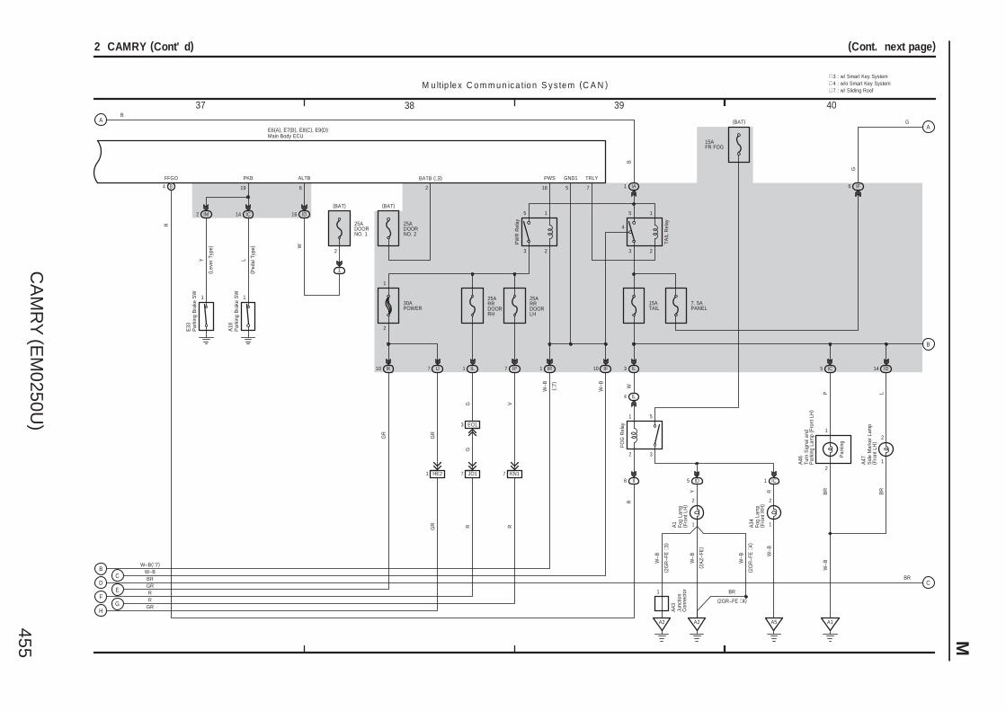
CA
MR
Y (E
M0250U
)455 M
L
1
14 IC
19
PKB
25ADOORNO. 1
2
1
(BAT)
ID16
W
ALTB
6
A18
B
M u ltip le x C o m m u n ic a tio n S y s te m (C A N )
(BAT)
2
BATB (∗3)
25ADOORNO. 2
15AFR FOG
15ATAIL
(BAT)
IL3
IL4
W
II8
FFGO
B
R
IC1ID5
1
2
1
2
R
W–B
W–B
FOG
Rel
ay
A1
A34
3 2
4
5 1
IA1
IF10
R
TRLY
7
B
TAIL
Rel
ay
W–B
IR1
GND1
5
3 2
5 1
PW
R R
elay
PWS
18
E6(A), E7(B), E8(C), E9(D)
25ARRDOORLH
IP7
V
25ARRDOORRH
IL1
G
30APOWER
GR
2
1
KN17
R
JO17
EO13
RG
G
7. 5APANEL
IF6
A46
1
2
1
A2
IC5
PB
R
4
Y
2 3
1 5
37 403938
(Cont. next page)2 CAMRY (Cont' d)
Y
1
2 IM
E33
( Lev
er T
ype)
( Ped
al T
ype)
GRR
GRR
W–BW–B(∗7)
GR
HE21
GR
( ∗7)
A1
W–B
G
W–B
IJ7IK10
( 2G
R–F
E ∗
3)
A2
W–B
( 2G
R–F
E ∗
4)
A5
A47
2
1
ID14
LB
R
BR BR
A43
∗ 7 : w/ Sliding Roof
Fog
Lam
p( F
ront
LH
)
Par
king
Bra
ke S
W
Fog
Lam
p( F
ront
RH
)
Junc
tion
Con
nect
or
Turn
Sig
nal a
ndP
arki
ng L
amp
( Fro
nt L
H)
Sid
e M
arke
r La
mp
( Fro
nt L
H)
Par
king
Bra
ke S
W
Main Body ECU
Par
king
∗ 4 : w/o Smart Key System
( 2A
Z–FE
)
W–B
BR
(2GR–FE ∗4)
∗ 3 : w/ Smart Key System
A
BC
DE
FG
H
A
B
C
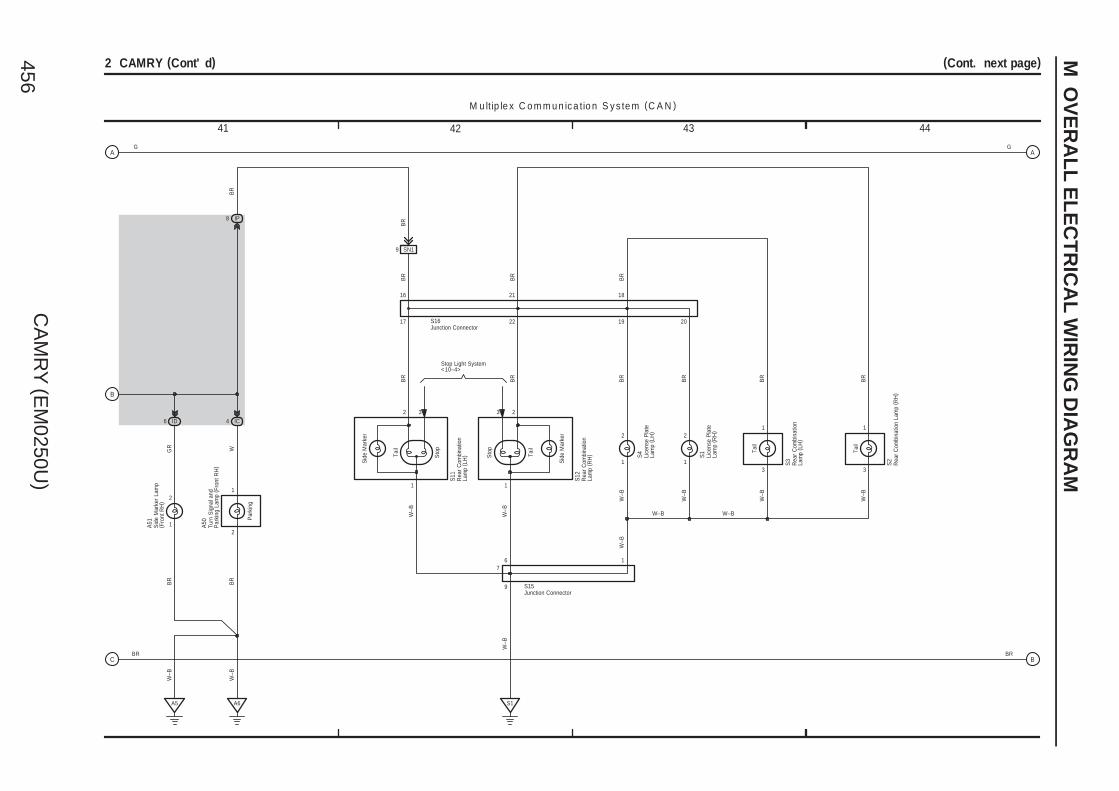
CA
MR
Y (E
M0250U
)456
M O
VE
RA
LL
EL
EC
TR
ICA
L W
IRIN
G D
IAG
RA
M
M u ltip le x C o m m u n ic a tio n S y s te m (C A N )
W
IP8
2
1
A50
IC4
BR
2
1
2
1
2
1
Tail
BR
BR
BR
BR
BR
BR
BR
6
S15
S1
W–B
W–B
W–B
1
BR
Tail
Tail
Sto
p
Sto
p
Tail
33
Stop Light System<10–4>
7
41 444342
(Cont. next page)2 CAMRY (Cont' d)
A6
W–B
A5
W–B
2
1
SN19
20192217
16 21 18
S16
BR
BR
W–B
W–B
W–B
W–B W–B
W–B
9
W–B
G G
BR
GR
1
2
A51
ID6
BR
S2
S3
S1
S4
S12
S11
BR BR
Turn
Sig
nal a
ndP
arki
ng L
amp
( Fro
nt R
H)
Sid
e M
arke
r La
mp
( Fro
nt R
H)
Lice
nse
Pla
teLa
mp
( RH
)
Rea
r C
ombi
natio
nLa
mp
( LH
)
Rea
r C
ombi
natio
nLa
mp
( RH
)Junction Connector
Junction Connector
Rea
r C
ombi
natio
n La
mp
( RH
)
Rea
r C
ombi
natio
nLa
mp
( LH
)
Lice
nse
Pla
teLa
mp
( LH
)
Par
king
3 3
1 1
Sid
e M
arke
r
Sid
e M
arke
r
A
B
C
A
B

CA
MR
Y (E
M0250U
)457 M
M u ltip le x C o m m u n ic a tio n S y s te m (C A N )
LGB
R3L4
3B4
3B9
E31
BR
3C4
3C9
2
17
G
5 3S
BR
3S11
ILL–
GB
R
7 3R
3R4
7
8
F4 F16
11
ILL+
4 3A
a1(B)
EAU IL+2
3T5
G
ILL–
ILL+
1
2
F5
4 3T
W–B
Ste
erin
g S
W R
H
Ste
erin
g S
W L
H
P
W–B
45 484746
2 CAMRY (Cont' d)
3T11
8
4
4B9
4D8
SWG
4B5
4D4
3Q4
BR
BR
GG
3A1
3T1
G
3T2
3U2
F1
W–B
A10D2
(∗12)C6(∗11 ∗14)C6
(∗11 ∗13)E12(∗11 ∗14)D12
F9( E
) , F1
0(F)
F6( A
) , F7
( B) ,
F8( C
) , F2
6(D
)
BR
Steering Pad SW
Tran
smis
sion
Con
trol S
W
A/C
Con
trol A
ssem
bly
Haz
ard
War
ning
Sig
nal S
W
Glo
ve B
ox L
amp
Rad
io R
ecei
ver
Ass
embl
y
Nav
igat
ion
Rec
eive
r A
ssem
bly
ILL–
ILL+
B8 B5
B R
A4 A12
P
LG
P
DIS
PV
oice
AU
TO/O
FF
TEM
P
TEL
Vol
ume
MO
DE
See
k
BR
G
Spiral CableE18(A), a1(B)
EAC
B2
GR
A9
R
8
SG
R
( ∗9)
(∗10)
3A9
3S12
R
∗11 : 8 Speaker∗12 : 6 Speaker
∗10 : Manual A/C∗ 9 : Automatic A/C
( ∗9)
(∗9)
( ∗9)
Sea
t Hea
ter
SW
E55
∗13 : w/ Navigation System∗14 : w/o Navigation System
(∗11 ∗13)F6E2
(∗12)B5
A/T Shift LeverIllumination
A
B
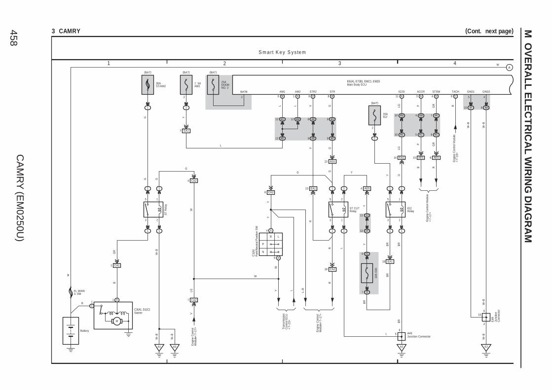
CA
MR
Y (E
M0250U
)458
M O
VE
RA
LL
EL
EC
TR
ICA
L W
IRIN
G D
IAG
RA
M
1 2 3 4
3 CAMRY (Cont. next page)
STR
(BAT)
1
7. 5AAM2
Y
A1
ACCR
B6
AM2
LL
AM1 STSW
B8D6
GV GR
15 AE5 8 AE5
TACH
3 A
STR2
4 D
B
C8
Eng
ine
Con
trol M
odul
e<
7–19
>B
R
2
P
G
IG2D
LG
11 A
BR
BR
IG2Relay
2
1
(BAT)
1 1
1 1
15
23
20AIG2
4G12 4M12
G
C3(A), D1(C)
M
B 1C
Battery
BG
R
W–B
P
N
B L
1 A
A1
1 CA1
C1(
A)
W
1
Y
1
1
ST
Rel
ay
1
15
23
R
18 CA2
R
R
L
ST CUTRelay
1 1
1 1
25
13
Y
3J12
3F12
G
30AST/AM2
1
(BAT)
Y O
Y
W–B
4E12
L
2
BATB
CA28
G
Y
L–BL
S m a rt K e y S y s te m
EA17
4G9
4F9
G
4K8
4E9
EA113
V
A3
W–B
CA24
G
A2
A436
5
Tran
smis
sion
Con
trol E
CU
<7–
23>
Eng
ine
Con
trol
Mod
ule<
7–17
>
WY
CA27
VLG
W
Eng
ine
Con
trol
Mod
ule<
7–17
>
EA118
10A
IGN
IG9
II7
BR
BR
AE54
Y
EA116
4M10
4E10
LG
AE613
G
4M4
4C5
4K7
4C9
P GR
Eng
ine
Con
trol M
odul
e<
7–17
>
FL MAIN3. 0W
W(BAT)
25ADOORNO. 2
BR
LJunction Connector
Par
k/N
eutra
l Pos
ition
SW
Starter
IM9
E2
2
6
GND2
4
W–B
W–B
W–B
Junc
tion
Con
nect
or
E49
W–B
5
GND1
10 IF
10
A4
A9
Main Body ECUE6(A), E7(B), E8(C), E9(D)
WA

CA
MR
Y (E
M0250U
)459 M
7 865
(Cont. next page)3 CAMRY (Cont' d)
B19 B18
SLR+ SLP
BR P
IGE SLP1
43
IG2 GND
M
SGND LIN B
6 1 2 5
W–B
7
W–B
O
20ASTRLOCK
1
2
(BAT)
B
O
AE5
3
L
LIN1
6
+BGND
C
EFIO EFII
O
14
LIN1
9 IR
7
Y G
E50
13 AE5
G
5
5
1
Engine Control Module<7–17>
8
CANH
C6
CANL
O
WW–B
O P
W–B
E51
4M1
4F8 7 4F4A8
4A2
4D3
B
Mul
tiple
xC
omm
unic
atio
nS
yste
m (
CA
N) <
2–8>
EA111
10AIGN
IM14
(IG)
B
E1
W–B
2
1
E2
W–B
E49
4F3
W–B
4F10
4C11
4F5
4C4
GL
S m a rt K e y S y s te m
4G10
4A10
4G5
4A5PBR
O
P
CANLCANH
IG+ B
10AMPX–B
1A
(BAT)
7. 5AGAUGENO. 2
IG12
(IG)
F1
W–B
VGR
SB
EA1
3D1
3Q12
V
W–B
3Q7
3U2
A12 A17 A18
10ADOME
1
2
(BAT)
R
LG
IF7
ID13
3L12
3Q1
R
3G2
3Q9
A13 A1 A2
GR
GR V
2
R
Multiplex CommunicationSystem (CAN)<2–3><2–4>
B2
E2
A24
3Q5
3D10
15EA1
A17
B18 CA34
C7
3
BR BR
GR
W–B
GR
BR
A41
( A) ,
A42
( B)
ES
Mas
ter
War
ning
+B(DOME)
DRIVE ICMICRO COMPUTER
Power Supply Circuit
MULTI LCD
W
W–B
F1( A
)
Buzzer
Junc
tion
Con
nect
or
Junc
tion
Con
nect
or
ID Code Box
SteeringLock ECU
Com
bina
tion
Met
er
JunctionConnector
C57
CANP
16 C
CANN
15 C
3
Main Body ECUE6(A), E7(B), E8(C), E9(D)
W W
CANI/F
A A
B
C

CA
MR
Y (E
M0250U
)460
M O
VE
RA
LL
EL
EC
TR
ICA
L W
IRIN
G D
IAG
RA
M
9 10 11 12
(Cont. next page)3 CAMRY (Cont' d)
O
CANL CANH
W–B
W
W
E1
B17 B16
SSW1
B14 B15
SSW2
B25
7 2 13 12 11
VC5
INDW INDS SWIL
GND COM
5 4
8
G
9
GR
1410
CODE TXCT AGND
Mul
tiple
x C
omm
unic
atio
nS
yste
m (
CA
N) <
2–8>
LIN
4 4E 5 4E
INDW INDS SWIL
P LG O
W–BO
W–B
E
SS1
SS2SS1
FullTraveling
Free
GNDPower SourceSystem<1–6><1–7>
SS2
4F1
W
A10 A17
A28 27 AA40A8A9A30
4D2
4F2
A2
HSW
RR
W
B24
1
2
AE22
R
4 4F
W–B
IND
Y
1 A A2
W
+B
4H5
AE221
LG
1A2
(BAT)
W
3J1
3C1
W
B3
A8
A41
( A) ,
A42
( B)
10AEFI NO. 1
4G4
4E3
4G11
4E11
4G8
4E8
P LG O
VC5CODETXCTAGND
GGRWR
W R
IG10
IM3
W–B
E2
4D3
2
1
W–B
W–B
Sec
urity
Indi
cato
r<
2–17
>
3E11
3J10
3A43
E58
( A) ,
E59
( B)
4L5
GND3
1 C
W–B
W–B
S m a rt K e y S y s te m
E52
W
Junc
tion
Con
nect
or
JunctionConnector
Power SW
Cer
tific
atio
n E
CU
Junc
tion
Con
nect
or
E49
Engine HoodCourtesy SW
A5
Main Body ECUE6(A), E7(B), E8(C), E9(D)
W WA
B
C
A
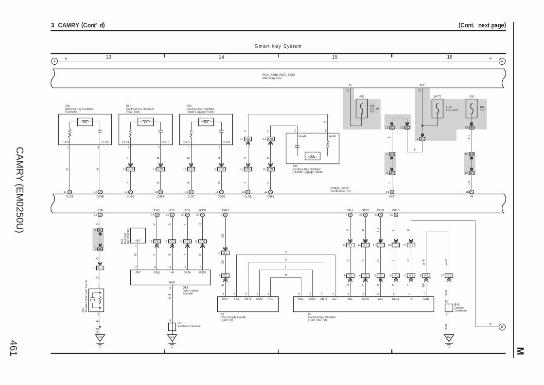
CA
MR
Y (E
M0250U
)461 M
13 161514
(Cont. next page)3 CAMRY (Cont' d)
12 4A
EO1
CG5BR
RSSI
Y
RDA
R
5
RSSI
Y
3
DATA+5
RC0
GG
2
CG1B
L5
LL
5
A3
BZR
1
P
3
CLG5
CLGB
OO
B
CLG4
N11
CLG6 CG6B
AE2
E56
CLG3
A
CLGB
31
5
CLGB
IE116
W–B
CLG1
LG
6
RLG
IE115
TSW1
X1
GR
IE1
GR
17
B
CLG
103
SEN1
BB
2
V
TRG+
X2
456
SEL
13 IE1
SEL1
IE114
SENS
6
VV
O Y
1
+B
IE112
RR
BR
E2
7
GND
CLG8 CG8B
1
2
E58(A), E59(B)
Y B
G
R
1
1 9 8 3 2
SGT ANT1 ANT2 TRG– TRG– ANT2 ANT1 SGT
W
GND
BY
12 EN1
V P
16 EN1
PV
15
IG
3C12
L LG
IGACC
10AECU IGNO. 1
(IG)
L
13
O18
A21 A29 A38 A39 A3
A11 A12
W
A13
R
A14
A22 A33 A34
A31 A32 A18A19
W–B
W–B
E49
A48
4F126 4F
5 4D
W–B
3
CLGBCLG6
N25
CLG7 CG7B
R WWR
A15 A16
EN111 EN115
14 EO113 EO112
O1
W–B
2
EN114 EN113
10AIGN
(IG)
IM13
LG
R6
O21
11
37 A
4
VV
ASEL
ASEL
EO1
1
ANT
O19
W–B
4F11
4K9
O
SN112 SN113
V P
IF2
3L11
L
IX17 IX16 IX14 IX13 IX12 IX11 IX18 IE217
(ACC)
7. 5AECU–ACC
ACC
22
S m a rt K e y S y s te m
W
7
ANT
Wire
less
Doo
r Lo
ck B
uzze
r
JunctionConnector
Electrical Key Oscillator(Console)
Certification ECU
Electrical Key Oscillator(Rear Seat)
Electrical Key Oscillator(Inside Luggage Room)
Door ControlReceiver
Ele
ctric
alK
ey A
nten
na
Junction Connector
Door Outside Handle(Front LH)
Electrical Key Oscillator(Front Door LH)
2 1
CLGB CLG5
V
Electrical Key Oscillator(Outside Luggage Room)
S14
Main Body ECUE6(A), E7(B), E8(C), E9(D)
W WA A
B

CA
MR
Y (E
M0250U
)462
M O
VE
RA
LL
EL
EC
TR
ICA
L W
IRIN
G D
IAG
RA
M
17 201918
3 CAMRY (Cont' d)
CLG CLGB +B
5 71
SENSTRG+
HE115
TSW2
LL
B
W1
16
S1
12HE1
BR
14
PB
R
CG2B
HE116
CLG2
GR
RG
R
SEL2
HE1
SEN2
O
3
VO
SEL
13 HE1
PP
O
RR
Y17 HE1
BR
E2
GND
W2
5
W–B
2
G O
6 104
W
L
G
R
TSW5
G
O
G O
9 8 3 2
SGT ANT1 ANT2 TRG– TRG– ANT2 ANT1 SGT
EN219
TKUL
C2B24
RCTY
IO7
Multiplex Communication System (CAN)<2–12><2–21><2–23><2–24><2–25><2–26><2–27>
DCTY PCTYLCTY LGCY HAZ
17
LSWPILE LSWL ACT+ ACT–
3
LSWD
12021 9 B25
HORN
A27
A4 A6 A23 A35 A36
A7
P
A231
Y
S–HORNRelay
LSH–
P
B20
AE612
W–B
W–B
W–B
HE217
EN117
14 SN1 SN15
10ADOME
1
2
(BAT)
3H12
R
4A1
RR
4E14E2
3L12
LG
E58(A), E59(B)
A21 A7A25 C4
G
R
HW17 HW16 HW14 HW13 HW12 HW11 HW18
ID13
IF7
R
2
1
3
2
S9
S8
9
1S15
W–B
W–B
W–B
1D11 1A5
7. 5AS–HORN
1G1
W
S m a rt K e y S y s te m
2
5
E49
W–B
Y
SecurityHorn
Junc
tion
Con
nect
or
Certification ECU
Junction Connector
Lugg
age
Com
partm
ent D
oor
Lock
Cyl
inde
r
Lugg
age
Ele
ctric
al K
ey S
W
B5
ACTD
Door Outside Handle(Front RH)
Electrical Key Oscillator(Front Door RH)
Multiplex Communication System (CAN)<2–11><2–21><2–22><2–23><2–27>
STP
23
Sto
p La
mp
SW
<10
–3>
Main Body ECUE6(A), E7(B), E8(C), E9(D)
W
5 A
LSWR
B1
TR+
A
B

CA
MR
Y (E
M0250U
)463 M
1 2 3 4
4 CAMRY
L–B
F1( A
)
18 CA2 CA2
R
4 CA2
Battery
CA11
3 2
5 1
1 1
1 1
W–B
A1
B
(IG)
P
N
BL
4
5
3
7
AM2
AM1
ACC
IG1
ST1
IG2
ST2
R
G
B
Tran
smis
sion
Con
trol
EC
U<
7–23
>
FL MAIN3. 0W
1G1
IH16
1C 1F1
30A
ST/
AM
2
1
7. 5
A A
M1
IA1
II4
B B
W
120A
ALT
B
B
E23
GR
AE71L
AE72L
10AGAUGENO. 1
C h a rg in gS ta r tin g (w /o S m a rt K e y S y s te m )
A A
B
8
P
W–B
B
C1(
A) ,
( B)
B
ST
Rel
ay
O
SB
10
W
1 2
7 CA2
5 B (2AZ–FE)9 A
Eng
ine
Con
trol
Mod
ule
<7–
17>
<8–
11>
(2GR–FE) Tran
smis
sion
Con
trol
EC
U<
7–23
>
4 A (2GR–FE)4 B (2AZ–FE)
Eng
ine
Con
trol
Mod
ule
<7–
17>
<8–
10>
10 CA2
14 EA1
2 CA2
B11
7. 5AGAUGENO. 2
12 IG
(IG)
3G2
3Q9
GR
GR
3 EA1
( 2G
R–F
E)
W–B
CA39
A3
53E
53F
A41(A), A42(B)
EA16
Y
Y
L
∗ 1 : 2AZ–FE A/T
VLG
( ∗1)
( ∗1)
( ∗1)
( A/T
)
( A/T
)
R
( M/T
)
G
( M/T
)
R
( M/T
)
P
( 2G
R–F
E)
( 2A
Z–FE
)
(2GR–FE)
O
L
Y
(2GR–FE)
LG
( A/T
)
Y
1
A13
A23
W( A
/T)
R
( M/T
)
R(M/T)
R(M/T)
W(A/T)
GR
GR
Cha
rge
CHG–
IG2
IG+
Junction Connector
Par
k/N
eutra
lP
ositi
on S
W
Ignition SW
Com
bina
tion
Met
er
C1 B2
B1 B4
Y
G–R
R
B IG
LS
C18
( B) ,
C19
( A) ,
( C)
IC Regulator
Gen
erat
or
( 2A
Z–FE
)E
ngin
e C
ontro
l Mod
ule
<8–
9>L
B3
M
G–R
CA25
2
(BAT)
1
W
7. 5AALT–S
C
B11
(A/T)A1(M/T)
M
Sta
rter
C3(
A) ,
C29
( B) ,
D1(
C)
Clu
tch
Sta
rt S
WA
22
2
1
(2GR–FE)A1(2AZ–FE)
FE311
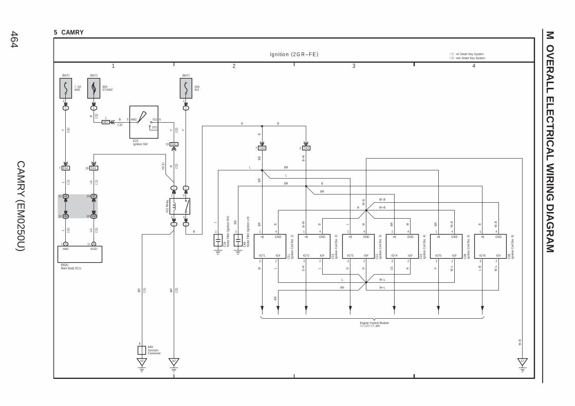
CA
MR
Y (E
M0250U
)464
M O
VE
RA
LL
EL
EC
TR
ICA
L W
IRIN
G D
IAG
RA
M
1 2 3 4
5 CAMRY
1
2
(BAT)
2
1 5
GND
IGT4
3
41
CA37
1 4
3
IGT1
GND+B
BR B
W
1 4
3
IGT2
GND+B
B–W B
G–R
1 4
3
C11 IGT3
GND+B
L W
G LG
WBR
+B
1 1
1
1
C13
C12
C14
A2
Ig n it io n (2 G R – F E )
3
1
Y
B
L
IG2
Rel
ay
C16
Engine Control Module<7–17><7–18>
GND
IGT5
3
41
P
W–BBR
+B
C38
GND
IGT6
3
41
L–B
W–BB
+B
C39
1B
R
C49
C7
IGF
2
W–L
IGF
2
W–L
IGF
2
R
IGF
2
R
IGF
2
L
IGF
2
L
W–B
BR
B
BR
BR
BR
1
( ∗1)
(BAT)
AM2
1 A
L
4E12
4M12
( ∗1)L
∗ 2 : w/o Smart Key System∗ 1 : w/ Smart Key System
EA17
A2
6
7. 5AAM2
20AIG2
ST2
IG2AM2 65
E23
(BAT)
30AST/AM2
1
1AE7
EA110
4E10
4M10
EA116
B ( ∗2)
B
(∗2)
Y ( ∗2)
O( ∗
1)
B ( ∗2)
LG ( ∗1)
Y ( ∗1)
LG ( ∗1)
A11
IG2D
2
E6(A)
BR
( ∗1)
BR
( ∗2)
A43
B
B
CA32
W–L
W–LBR
L
W–B
W–B
BR
L
L
BR
B
B–W
B
W–B
JunctionConnector
Igni
tion
Coi
l (N
o. 1
)
Igni
tion
Coi
l (N
o. 3
)
Igni
tion
Coi
l (N
o. 2
)
Igni
tion
Coi
l (N
o. 4
)
Noi
se F
ilter
(Ig
nitio
n R
H)
Igni
tion
Coi
l (N
o. 5
)
Igni
tion
Coi
l (N
o. 6
)
Noi
se F
ilter
(Ig
nitio
n LH
)
Ignition SW
Main Body ECU
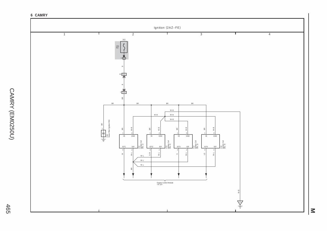
CA
MR
Y (E
M0250U
)465 M
1 2 3 4
6 CAMRY
15AINJ
IH
(IG)
GND
IGT4
3
41
CA37
1 4
3
IGT1
GND+B
BR
W–B
W
1 4
3
IGT2
GND+B
BR
W–B
G–R
1 4
3
C11 IGT3
GND+B
BR
W–B
G LG
W–BBR
+B
1
C13
C12
C14
Ig n it io n (2 A Z – F E )
W–B
BB
BR
C16
Engine Control Module<8–10>
C4
IGF
2
W–L
IGF
2
W–L
IGF
2
W–L
IGF
2
W–L
W–B
BR BRBR
W–L
BR
BR
EA110
7
W–B
W–B
W–L
W–L
BR
Igni
tion
Coi
l( N
o. 1
)
Igni
tion
Coi
l( N
o. 3
)
Igni
tion
Coi
l( N
o. 2
)
Igni
tion
Coi
l( N
o. 4
)
Noi
se F
ilter
(Ig
nitio
n R
H)
W–B

CA
MR
Y (E
M0250U
)466
M O
VE
RA
LL
EL
EC
TR
ICA
L W
IRIN
G D
IAG
RA
M
1 2 3 4
(Cont. next page)7 CAMRY
(BAT)
1E
Pum
p
1E 1E
A3
M
N1
5
4
1A
BR
E n g in e C o n tro l (2 G R – F E )
N10
1E 1D
1E
1
2
Y
(IG)
IG9
GR
W–B
CA21
3 2
5 1
11
11
(BAT)
1
Y
2
∗ 2 : w/o Smart Key System∗ 1 : w/ Smart Key System
A2
BR
B
CA12
W
O
(∗1)
30AEFI MAIN
10AIGN
20AIG2
10AEFINO. 3
2
1
15AEFINO. 2
2
1
1
11
1E7
20AA/F
1E11
A1
L
12 4M
12 4E
( ∗1)
L
A1
AM2
(BAT)
( ∗1)
1
7 EA116 EA1
7. 5AAM2
4E10
4M10
LG ( ∗1)
Y ( ∗1)
LG ( ∗1)
A11
IG2D
2
E6(A)
3F12
3K12
A1
B6
A2
6
1E9
Battery
FL MAIN3. 0W
W
1G1
EFIRelay
12
106
W–B
W–B
BR
BR
BRL O W
R R
GR
W
4 13 8
12
B
Y
LG
A58
( A) ,
E40
( B)
GR Y
NA19
W–B
A/FRelay
IG2Relay
BR
( ∗2)
( ∗1)
A43
W
GR
GR
R
R
O
B
L
C/OPNRelay
Y
BR
( ∗2)
30AST/AM2
1
(BAT)
EA110B
(∗2)
ST2
IG2AM2 65
E23
Y
Y
(∗2)
(∗2)
1AE7
B
B ( ∗2)
(∗2)
Junction Connector
Junc
tion
Con
nect
or
Ignition SW
Main Body ECU
Fuel
Suc
tion
Pum
p an
d G
age
Ass
embl
y
Y
B
GR
A
B
C
D
E
F
G
H
I

CA
MR
Y (E
M0250U
)467 M
7 865
(Cont. next page)7 CAMRY (Cont' d)
A
FC
PRG
B
2
1
BG
–R
E2G
B
4
LG
VG
B
5
L–B
THA
B
1
P
3
+B
E2G VG THA
Y
R
C6
E n g in e C o n tro l (2 G R – F E )
717273108
7
ACIS
B
1
2
B–W
C48
107
ETHA
B
2
G–R
E2
74
C2
2
1
C7
W
B
# 10
B
45
2
1
C9
W
B
# 20
R
85
2
1
C8
W
B
# 30
Y
44
2
1
C10
W
B
# 40
L
84
2
1
C36
W
B
# 50
W–L
43
2
1
C37
W
B
# 60
BR
83
W W W W
B1 B2
A10
A8 A9
B4
10AEFI NO. 1
1A2
(BAT)
NA112NA116NA114 NA13NA113NA15 NA14
CA310CA214 CA213CA212
C4
CA232
1
GR B
GW BR YB
W–B GR
OGRW
–B
B YBRW G
W–B
A41
( A) ,
A42
( B)
W
GR
GR
R
R
O
B
L
W
BR
W Y
A41
( A) ,
A42
( B)
A
BATT
20
Y
8 2 43
G RL
W–B
MPMPVPMP EPPM VCPPPPMP
W–L
B
A34A42 B76 B75B77
R
W–L
W–L
W–L
R
B
W–L
L–B
C34
ACM
B42
B
R
W–L
O
R
R
BR
L
A55(A), C55(B)
W
SGND
Leak DetectionPump
M
Canister PressureSensor
Ven
t Val
ve
VOUT VCC
6
W–B
MGNDMTRBVGNDVLVB
9
GR
N17
Junc
tion
Con
nect
or
Junc
tion
Con
nect
or
Engine Control Module
Fuel
Inje
ctor
(N
o. 4
)
Mass Air Flow Meter
VS
V (
AC
M)
Fuel
Inje
ctor
(N
o. 5
)
Fuel
Inje
ctor
(N
o. 6
)
VS
V (
AC
IS)
VS
V (
Pur
ge)
Fuel
Inje
ctor
(N
o. 1
)
Fuel
Inje
ctor
(N
o. 3
)
Fuel
Inje
ctor
(N
o. 2
)
Canister Pump Module
Y
1
A
B
C
D
E
F
G
H
I
A
B
C
D
E
F
G
H
I

CA
MR
Y (E
M0250U
)468
M O
VE
RA
LL
EL
EC
TR
ICA
L W
IRIN
G D
IAG
RA
M
9 10 11 12
(Cont. next page)
( Shi
elde
d)
111
M+
B
G
M–
B
R
GE01
B
7 CAMRY (Cont' d)
B
A1A+
B
A1A–
B
HA1A
A1A+ A1A– HA1A
3 4 1
L P G
B
A2A+
B
A2A–
B
HA2A
A2A+ A2A– HA2A
3 4 1
BR Y
B–W
2 2
+B +B
120 119
2
1
B
NE–
B
NE+
109
G R
( Shi
elde
d)
( Shi
elde
d)
( Shi
elde
d)
W B
E n g in e C o n tro l (2 G R – F E )
B
OX2B
B
EX2B
B
HT2B
OX2B E2 HT2B
3 4 1
OX1B E2HT1B
B
W–B Y
413
B
EX1B
B
HT1B
B
OX1B
BR
LGW
2
+B
C52
( Shi
elde
d)
C51
411819
110 861169388 48 65476487
B B
34 2 1
VTA2
B
W–L
99
ETA
B
P
97
W–L
R
W–L
78
P
B
THW
B
ETHW
B
79
1
2
96
B
B
VCTA
56
VTA1
B
Y
98
VTA VC VTA2 E2 M+ M–
C5
G–R
+BM
A
1
LG(BAT)
3
2
1 ID
Y
A
IGSW
10AIGN
IG9
ST1–
A
Sto
p Li
ght S
yste
m<
10–2
>
GR
A19
(IG)
2835
C50
C15 C35
C5
MREL
44 A
ORR
+B2
1 A
+B
2 A
ACIV
4 A
1
2
A2
B2
VV
A56
( A) ,
A57
( B)
B
A53
R
R
O
BR
L
BR
( Shi
elde
d)
( Shi
elde
d)
( Shi
elde
d)2
+B
R
(Shielded)
10AETCS
3F12
3K12
A2
B6
YYY
B
A58
( A) ,
E40
( B)
BR
L
A55(A), C55(B)
B
C5
B
Sto
p La
mp
SW
VS
V( A
ir In
take
Con
trol)
Engine Control Module
Sho
rt C
onne
ctor
Junc
tion
Con
nect
or
Air Fuel Ratio Sensor(Bank 1 Sensor 1)
Air Fuel Ratio Sensor(Bank 2 Sensor 1)
Throttle Body Assembly
Cra
nksh
aft
Pos
ition
Sen
sor
Heated Oxygen Sensor(Bank 2 Sensor 2)
Heated Oxygen Sensor(Bank 1 Sensor 2)
Eng
ine
Coo
lant
Tem
p.
Sen
sor
C4
1 4
32
A
B
C
D
E
F
G
H
I
A
B
C
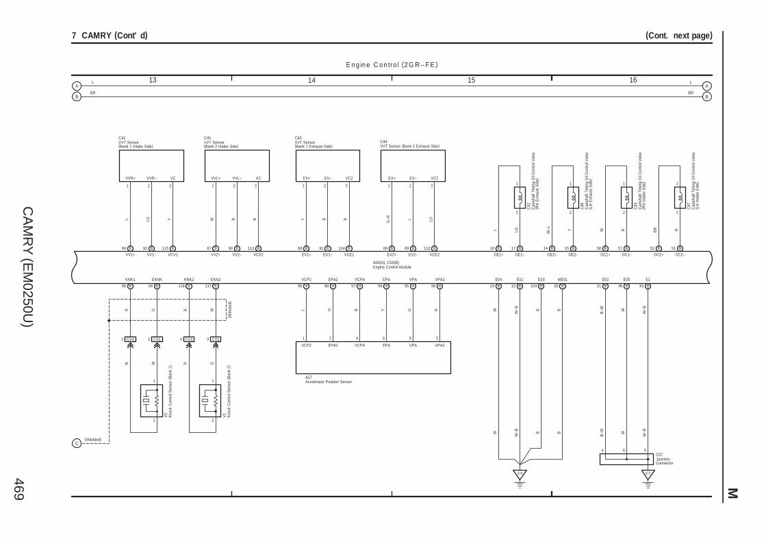
CA
MR
Y (E
M0250U
)469 M
13 161514
(Cont. next page)
20 46 81B
ME01
B
E05
B
E1
B W
7 CAMRY (Cont' d)
2
1
B
EKN2
B
KNK2
CV14
1
2
B
EKNK
B
KNK1
CV11CV12
OE1+
B
OE1–
B
2
1
OE2+
B
OE2–
B
2
1
OC2+
B
OC2–
B
OC1+
B
OC1–
B
1
22
1
C46
C42
C47
C43
V2
V1
W–L YL LG BR RW B
R G B WGRWB
( Shi
elde
d)
1171189495
5152575815141716
C7
CV13
W–BB
23 22 104B
E04
B
E01
B
E03
W W–B
C4
B69 B92 B115 B90B67 B113 B68 B91 B114 B66 B89 B112
VV1+ VV1– VCV1 VV2–VV2+ VCV2 EV1+ EV1– VCE1 EV2+ EV2– VCE2
VC2EX–EX+VC2EX–EX+VCVVL+ VVL–VCVVR–VVR+
L LG Y BW R Y B R
G–R L LG
1 2 3 21 3 1 2 3 1 2 3
C41 C45 C40C44
A A A A A A565559576058
VPA2VPAEPAVCPAEPA2VCP2
L O B Y G R
VCP2
1
EPA2
2
VCPA
4
EPA
5
VPA
6
VPA2
3
A17
(Shielded)
B
E02
B–W
4
21
6 5C57
W–BB B WB
–WW W–B
E n g in e C o n tro l (2 G R – F E )
BR
L
BR
L
A55(A), C55(B)
Accelerator Position Sensor
Engine Control Module
VVT Sensor(Bank 1 Exhaust Side)
VVT Sensor(Bank 1 Intake Side)
Cam
shaf
t Tim
ing
Oil
Con
trol V
alve
( RH
Exh
aust
Sid
e)
Cam
shaf
t Tim
ing
Oil
Con
trol V
alve
( RH
Inta
ke S
ide)
VVT Sensor (Bank 2 Exhaust Side)VVT Sensor(Bank 2 Intake Side)
Cam
shaf
t Tim
ing
Oil
Con
trol V
alve
( LH
Exh
aust
Sid
e)
Cam
shaf
t Tim
ing
Oil
Con
trol V
alve
( LH
Inta
ke S
ide)
JunctionConnector
Kno
ck C
ontro
l Sen
sor
( Ban
k 2)
Kno
ck C
ontro
l Sen
sor
( Ban
k 1)
A
B
C
A
B

CA
MR
Y (E
M0250U
)470
M O
VE
RA
LL
EL
EC
TR
ICA
L W
IRIN
G D
IAG
RA
M
17 201918
(Cont. next page)
E n g in e C o n tro l (2 G R – F E )
7 CAMRY (Cont' d)
10
STAR
B
STA
A
11
STSW
A
NSW
B
STP
A
Sto
p La
mp
SW
<10
–3>
Mai
n B
ody
EC
U<
3–4>
24
IMO
A
IMI
A
ID C
ode
Box
( ∗1)
<3–
6>Tr
ansp
onde
r K
ey E
CU
( ∗2)
<9–
3>
TC
A
Dat
a Li
nk C
onne
ctor
3<
9–2>
W
P
G Y
A55(A), C55(B)
C ru is e C o n tro l (2 G R – F E )
A
ACCR
V R
ST
CU
T R
elay
<3–
3>
ST
Rel
ay<
3–2>
<4–
2>
BR L–B
W
A
3
SSFTDSFTU
2
5
71
G L YO
BR
R
E31
3662 13144863 27
IGF1
B
IGT1
B
IGT2
B
IGT3
B
IGT4
B
IGT5
B
IGT6
B
Ignition Coils<5–2><5–3><5–4>
BR W G–R G LG P L–B
353637383940106
R L Y
CANH
A
CANL
A4941
Mul
tiple
x C
omm
unic
atio
nS
yste
m (
CA
N)
<2–
2>
40
CCS
A
GR
W
BR
E IG
RFC
A
Coo
ling
Fan
EC
U<
26–1
>G
43
TACH
A
B
15
SPD
A
Com
bina
tion
Met
er<
25–1
>V
8
AE55AE510 AE520 AE511
E le c tro n ic a lly C o n tro lle d T ra n s m is s io na n d A /T In d ic a to r (2 G R – F E )
CAN+
B
CAN–
B
B Y
12
16
SFTU
A 51
SFTD
A 25
S
A
P
B
N
B
B–W L–
B
2724
R
B
G
L–B
P
BR
L
70
PSW
B
1
B
C17
Par
k/N
eutra
l Pos
ition
SW
<3–
3><
4–2>
AE512
P
AE56
4L9
4C10
4A9
B B
B
B B
(∗2)
( ∗2)( ∗
1)
Mai
n B
ody
EC
U<
3–4>
Dat
a Li
nkC
onne
ctor
3<
9–1>
Dat
a Li
nkC
onne
ctor
3<
9–1>
D
B26
R
B25
P G
B–W
Y
O
BR
L
C7
3
CA34
B18
A17
EA115
4C12
4A11
3A11
3H10
3D10
b1( C
)E
18( A
) , b1
( C)
W–B
BR
BR
GR
W–B
BR
BR
A41
( A) ,
A42
( B)
C57
BR
AE517
∗ 2 : w/o Smart Key System∗ 1 : w/ Smart Key System
( ∗1)
( ∗1)
Junc
tion
Con
nect
or
Engine Control Module
Power SteeringOil PressureSW
Junc
tion
Con
nect
or
Spi
ral C
able
Tran
smis
sion
Con
trol S
W
ON–OFF
+RES
–SET
CANCEL
A
B R
2
ECC
A1
CCS
C4 C3
Cru
ise
Con
trol S
W
( ∗1)
( ∗1)
( ∗1)
A
B
A
B
C
D
E
F
G
H
I
J
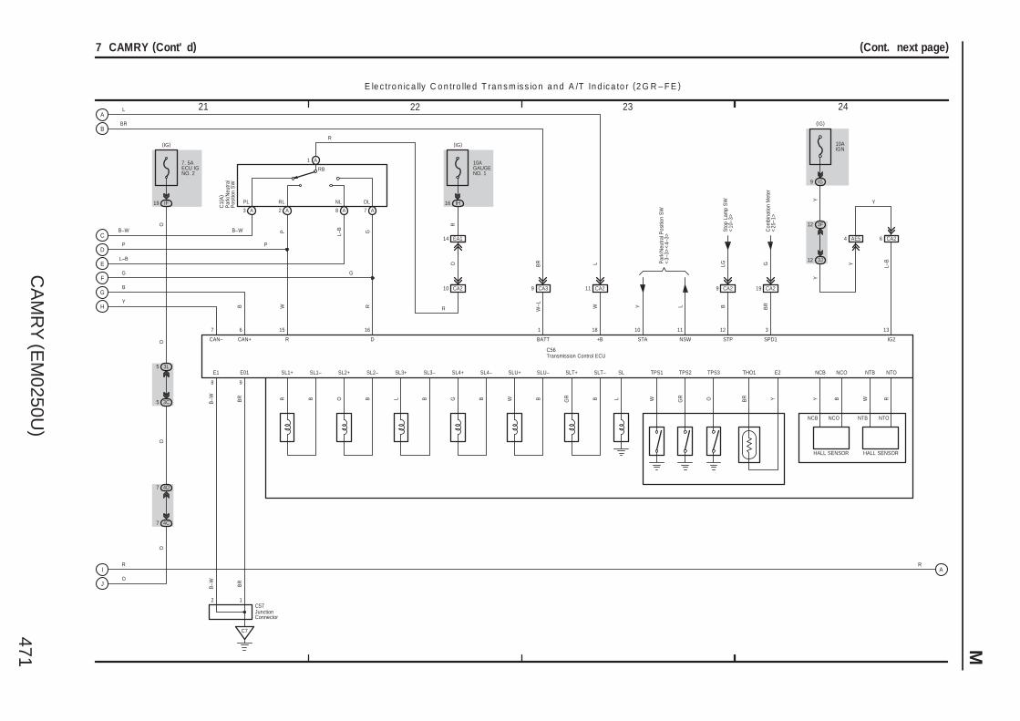
CA
MR
Y (E
M0250U
)471 M
21 242322
(Cont. next page)7 CAMRY (Cont' d)
W R
IF19
(IG)
O
R
C56
BR YBRBWBG BGR
SL1+ SL1– SLT+ SLT–SL4+ SL4– SLU+ SLU– THO1 E2
R D
EA114
10AGAUGENO. 1
IH16
(IG)
R
E le c tro n ic a lly C o n tro lle d T ra n s m is s io n a n d A /T In d ic a to r (2 G R – F E )
SL2–SL2+
O BSL3–SL3+
L B
TPS3TPS2TPS1SL
GRW OL
10
STA
Y
11
NSW
L
12
STP
Sto
p La
mp
SW
<10
–3>
LG
13
IG2
18
+B
W
1
BATT
W–L
4D7
4C7
7
CAN–
6
CAN+
B
E1
B–W
8
E01
BR
9
C7
15 16 3
SPD1
Com
bina
tion
Met
er<
25–1
>G
DLNLRLPL
RB
P L–B G
G
B
R
L–B
P
Y
B–W
P
G
C1(
A)
R
CA210
O
R
7. 5AECU IGNO. 2
O
3L5
3C5
O
OO
BR
L
12C57
B–W BR
CA211CA39
BR L
10AIGN
IG9
(IG)
3F12
3J12
AE54 CA26
CA29
B BR
CA219
YY
Y L–B
Y
Par
k/N
eutra
lP
ositi
on S
W
Transmission Control ECU
JunctionConnector
NTBNCONCB NTO
HALL SENSOR HALL SENSOR
Y B W R
NCB NCO NTB NTO
A1
A3 A2 A8 A7
B–W
Par
k/N
eutra
l Pos
ition
SW
<3–
3><
4–3>
A
B
C
D
E
F
G
H
I
J
A

CA
MR
Y (E
M0250U
)472
M O
VE
RA
LL
EL
EC
TR
ICA
L W
IRIN
G D
IAG
RA
M
25 282726
7 CAMRY (Cont' d)
E le c tro n ic a lly C o n tro lle d T ra n s m is s io n a n d A /T In d ic a to r (2 G R – F E )
R
R
3P9
3B3
E2
B2IG+ B
10AMPX–B
1A
(BAT)
7. 5AGAUGENO. 2
IG12
(IG)
F1
W–B
VGR
SB
EA1
3D1
3Q12
V
3Q7
3U2
A12 A17 A18
F1( A
) , F2
( B)
10ADOME
1
2
(BAT)
R
LG
IF7
ID13
3L12
3Q1
R
3G2
3Q9
A13 A1 A2
GR
GR V
2
R
Multiplex CommunicationSystem (CAN)<2–3><2–4>
CANH CANL
A24
3Q5
3D10
15EA1
A17
B18
CA34
C7
3
BR BR
GR
W–B
GR
BR
A41
( A) ,
A42
( B)
C57
ES
IG2
Cru
ise
DRIVE ICMICRO COMPUTER
Power Supply Circuit
LCDA/T Range
W–B
IG2
Mal
func
tion
Indi
cato
r La
mp
DRIVE IC
P R N D S
B4
CHK
Tem
p.
Tach
omet
er
Buzzer
Mas
ter
War
ning
Junc
tion
Con
nect
or
Junc
tion
Con
nect
or
Com
bina
tion
Met
er
3
+B(DOME)
CANI/F
MULTI LCDSpe
edom
eter
A

CA
MR
Y (E
M0250U
)473
Mem
o

CA
MR
Y (E
M0250U
)474
M O
VE
RA
LL
EL
EC
TR
ICA
L W
IRIN
G D
IAG
RA
M
1 2 3 4
8 CAMRY (Cont. next page)
E n g in e C o n tro l (2 A Z – F E )
1
(BAT)
1E
Pum
p
1E 1E
A1
7 1E
M
N1
5
4
BR
N10
1E
2
1
6 11
1D
1E
YB
2
(IG)
IG9
GR
W–B
12
10AEFINO. 3
10AIGN
30AEFI MAIN
15AEFINO. 2
2
1
1
1
R
1
3F12
3K12
B6
A1
1E9
EFIRelay
L O
R GR
12
813
YY
LG
LG
A58
( A) ,
E40
( B)
YGR
NA19
W–B
CA21
15AINJ
IH8
(IG)
EA11
CA12C/OPNRelay
W
W–B
BR
BR
W
Y
O
R
R
W
V
W
Ven
t Val
ve
Canister PressureSensor
M
Leak DetectionPump
SGND VOUT VCC
432
VGND
8
VLVB
91
MTRBMGND
6
N17
NA114 NA13NA113
CA214 CA21312 CA2
BR YB
B YBR
G RL
71 B 70 B
EPPM VCPPPPMP
94 B
NA116
CA310
C6
W–B
W–B
W–B
W–B
NA15NA14
G WWG
MPMP VPMP
42 A34 A
B1
A10
NA112
GR
GR
O
A41
( A) ,
A42
( B)
A24(A), C24(B)
O
Engine Control ModuleJunc
tion
Con
nect
or
Junc
tion
Con
nect
or
Fuel
Suc
tion
Pum
pan
d G
age
Ass
embl
y
Can
iste
r P
ump
Mod
ule
1E10
A17
B16
A3
BR
W–B
W–B
Junc
tion
Con
nect
orA
41( A
) , A
42( B
)
BR
W–B
CA23
GR
GR V
A
B
C
D
E
F
G
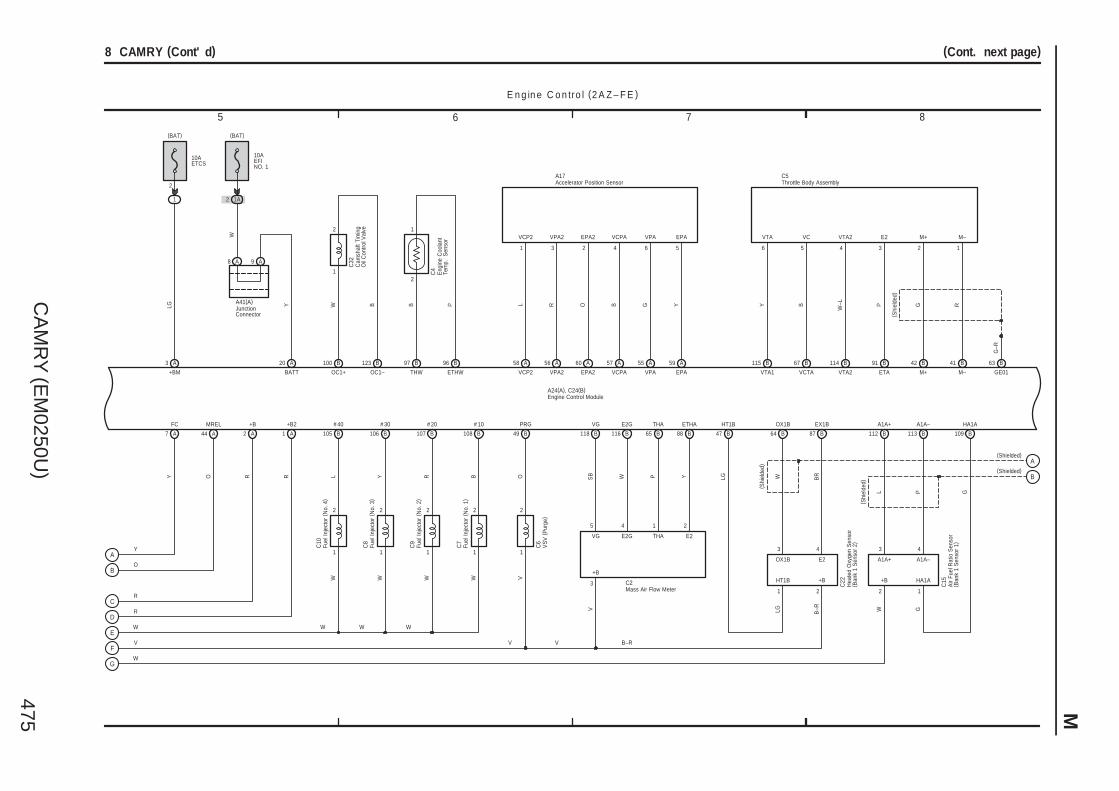
CA
MR
Y (E
M0250U
)475 M
7 865
(Cont. next page)8 CAMRY (Cont' d)
1
2
1
2
B
A 57 55A
R GL
EPA2
A
EPA
60
VCP2 VCPA
59
VPA2 VPA
O
56
Y
A58 AA
A17
6 5431 2
E n g in e C o n tro l (2 A Z – F E )
W
W W W W
L Y R B
B105 B106 B107 B108
# 40 # 30 # 20 # 10
W W
V
A2 A1
R R
+B +B2
B49 B118 B116 B65 B88
O SB W P Y
2
A3
1
LG
+BM
(BAT)
C6
V
V
V
C2
VG E2G THA E2
+B
3
5 4 1 2
PRG VG E2G THA ETHA
C22
C15
B–R
HT1B OX1B EX1B A1A+ A1A– HA1A
B–R W
HT1B +B +B HA1A
OX1B E2 A1A+ A1A–
( Shi
elde
d)
W BR
( Shi
elde
d)
L P
LG
G
1 2 2 1
3 4 3 4
B47 B64 B87 B112 B113 B109
B115 B114B67 B91 B42 B41 B63
6 45 3 2 1
Y
W–LB P
( Shi
elde
d)
G R
VTA VTA2VC E2 M+ M–
C5
VTA1 VTA2VCTA ETA M+ M– GE01
G–R
B100 B123
OC1+ OC1–
W B
C32
B P
ETHWTHW
96 BB97
2
1
A24(A), C24(B)
20 A
BATT
Y
10AEFINO. 1
1A2
(BAT)
A8 A9
A44
MREL
7
FC
A
OY
W
V
W
R
R
O
Y
10AETCS
W
A41(A)
(Shielded)
(Shielded)
LG G
Accelerator Position Sensor
Engine Control Module
JunctionConnector
Air
Fuel
Rat
io S
enso
r( B
ank
1 S
enso
r 1)
Mass Air Flow Meter
Hea
ted
Oxy
gen
Sen
sor
( Ban
k 1
Sen
sor
2)
Cam
shaf
t Tim
ing
Oil
Con
trol V
alve
Throttle Body Assembly
VS
V (
Pur
ge)
VCP2 VPA2 EPA2 VCPA VPA EPA
Eng
ine
Coo
lant
Tem
p.
Sen
sor
C4
Fuel
Inje
ctor
(N
o. 4
)C
10
Fuel
Inje
ctor
(N
o. 3
)C
8
Fuel
Inje
ctor
(N
o. 2
)C
9
Fuel
Inje
ctor
(N
o. 1
)C
7
1
2 2
1 1
2
1
2
A
B
C
D
E
F
G
A
B

CA
MR
Y (E
M0250U
)476
M O
VE
RA
LL
EL
EC
TR
ICA
L W
IRIN
G D
IAG
RA
M
9 10 11 12
(Cont. next page)8 CAMRY (Cont' d)
1
2
2
1
2
1
RG
121 BB122
NE–NE+
BRY
98 B99 B
G2–G2+
C20
C31
( Shi
elde
d)
( Shi
elde
d)
B110 B111
KNK1 EKNK
G R
( Shi
elde
d)
C30
IGT1 IGT2 IGT3 IGT4 IGF1
B85 B84 B83 B82 B81
W G–R G LG BR
L
B–W
E02
44 B B43
ME01
B W
E04
46 B B45
E01
W–B
W–B
E1
104 B
C4 C6
E n g in e C o n tro l (2 A Z – F E )
SPD
A8
LC
ombi
natio
n M
eter
<25
–1>
STP
A36
WS
top
Lam
p S
W<
10–3
>
TC
A27
PD
ata
Link
Con
nect
or 3
<9–
2>
IMI
A11
Y
IMO
A10
G
TACH
A15
B
A24(A), C24(B)
B–W W–B
W–B
B–W
STA
A48
V
A21
FANL
R
22 A
W
FANH
FAN
NO
. 3 R
elay
<26
–4>
FAN
NO
. 1 R
elay
<26
–3>
41 A
CANH
49 A
CANL
(Shielded)
(Shielded)
B86
E03
B
B103 B93 B126 A33
B
B–W L
L
C33
3 1 2 5
VCIA IACA EIA IAC+
CA29
4
W
52 A
19 CA2
IAC–
A53
PSW
BR
1
CA32
CA31
W–B
B–W
50 B
L
ALT
Gen
erat
or<
4–3>
FAN
NO
. 2 R
elay
<26
–3> Ignition Coils
<6–2><6–3>
NSW
B52
SB
Par
k/N
eutra
l Pos
ition
SW
( A/T
) <4–
2>
ST
Rel
ay<
4–2>
AE56 AE512
P
W G
( ∗1)
( ∗1)
( ∗1)
( ∗1)
( ∗1)
( ∗1)
( ∗1)
CA33
B
C17
∗ 1 : California
BW–B
Mul
tiple
x C
omm
unic
atio
nS
yste
m (
CA
N) <
2–2>
Tran
spon
der
Key
EC
U<
9–3>
Engine Control Module
Pow
er S
teer
ing
Oil
Pre
ssur
e S
W
Cra
nksh
aft
Pos
ition
Sen
sor
Kno
ck C
ontro
lS
enso
r ( B
ank
1)
Cam
shaf
tP
ositi
on S
enso
r
Intake Air Control Valve
Dat
a Li
nk C
onne
ctor
3<
9–1>
B
M
VCIA IACA EIA IAC+ IAC–
B
( A/T
)
A
B
A

CA
MR
Y (E
M0250U
)477 M
13 161514
8 CAMRY (Cont' d)
GR
W
BR
CCS
40 A
CA34
3A11
3D10
GR
BR
BR
AE517
C ru is e C o n tro l (2 A Z – F E )
112510823
YGR L W BR G R
B78 B76 B79 B58 B72B75 B59
C25
SL1–SL1+
77 B57 B
LGL
6 13
S4 SLT+ SLT– DSL SL2+ SL2– THO1
Y G GR
SB
LG BR OW B
THOSL1–SL1+SL2–SL2+DSLSLT–SLT+S4
E le c tro n ic a lly C o n tro lle d T ra n s m is s io n a n d A /T In d ic a to r (2 A Z – F E )
7
BR
B95
ETHO
E2
O
G
B5654 BB53B73
R
C1(B)
P R N D
SB
PGR
NC–NC+NT–NT+
PLGWG
B101
1
2
B102124 B
2
1
125 B
C26
C27
G
GR
A24(A), C24(B)
1 ID
YA
IGSW
10AIGN
IG9
ST1–
A
GR
(IG)
2835
3F12
3K12
A2
B6
YYY
B
A58
( A) ,
E40
( B)
W–B
EA115
B16
A18 A16
A9
EOM
A32
EC
A3
A41
( A) ,
A42
( B)
W–B W
W–B
(Cont. next page)
1149
G O Y
B80 B60 B61
SR SL3+ SL3–
V R LSL3–SL3+SR
7. 5AECU IGNO. 2
IF19
(IG)
3L5
3K4
A4
B4
B19
A12
2
1
V
23
26 A 55 B
A21
A41
( A) ,
A42
( B)
A58
( A) ,
E40
( B)
O
BR
GW
P
O
(M/T)
(M/T)
( M/T
)
( M/T
)
( M/T
)( M
/T)
CA217
RG V
( A/T
)
R
B
GR
PL RL NL DL 2L LL
RB
Cru
ise
Con
trol
Clu
tch
SW
Engine Control Module
Junc
tion
Con
nect
or
Junc
tion
Con
nect
or
Junc
tion
Con
nect
or
Junc
tion
Con
nect
or
Park/Neutral Position SW
Electronically Controlled Transmission Solenoid
Tran
smis
sion
Rev
olut
ion
Sen
sor
( Tur
bine
)
Tran
smis
sion
Rev
olut
ion
Sen
sor
( Cou
nter
Gea
r)
b1( C
)E
18( A
) , b1
( C)
Spi
ral C
able
ON–OFF
+RES
–SET
CANCEL
A
B R
2
ECC
A1
CCS
C4 C3
Cru
ise
Con
trol S
W
Sto
p Li
ght S
yste
m<
10–2
>
A19
Sto
p La
mp
SW
B6 B1 B9 B7 B3 B8
B2
1 4
32
CA38
A
A
B
C
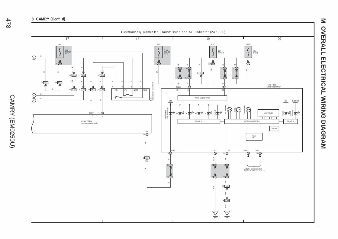
CA
MR
Y (E
M0250U
)478
M O
VE
RA
LL
EL
EC
TR
ICA
L W
IRIN
G D
IAG
RA
M
17 201918
8 CAMRY (Cont' d)
A24
BR
W
CA211
AE621
AE516
4
A25
SB
2 1
O L
A24(A), C24(B)
AT4 NSSD
10AGAUGENO. 1
IH16
(IG)
EA114CA210
R
R R
O
GR
B
CA216
AE622
CA215
AE619
O RYYW
BRG
6 5
R L
L
B74
E le c tro n ic a lly C o n tro lle d T ra n s m is s io n a n d A /T In d ic a to r (2 A Z – F E )
AE55
R
E31
R
7 IF
LG
R
(BAT)
2
1
10ADOME
18 A17 A12 A
2 3U
7 3Q
V
12 3Q
1 3D
EA1
SB
GR V
W–B
F1
(IG)
12 IG
7. 5AGAUGENO. 2
(BAT)
1A
10AMPX–B
3P9
3B3
ID13
3L12
3Q1
R
3G2
3Q9
A13 A1 A2
GR
GR V
2
R
Multiplex CommunicationSystem (CAN)<2–3><2–4>
A24
3Q5
3D10
BR
W–B
B4
R
EA115
CA34
C6
BR
GR
W–B
BIG+ B2
E2 CANH CANLES
IG2
Cru
ise
DRIVE ICMICRO COMPUTER
Power Supply Circuit
MULTI LCD
IG2
Mal
func
tion
Indi
cato
r La
mp
DRIVE IC
P R N D
4, 3
, 2, L
CHK
Tem
p.
Tach
omet
er
Buzzer
Mas
ter
War
ning
Engine Control Module
Tran
smis
sion
Con
trol S
W
NSSLATL
3
CANI/F
Combination MeterF1(A), F2(B)
+B(DOME)
Spe
edom
eter
A
B
C

CA
MR
Y (E
M0250U
)479 M
Ski
d C
ontro
l EC
Uw
ith A
ctua
tor
<12
–3>
<13
–3>
<14
–2>
CANL
3 IF
Y O GR G
R
Eng
ine
Con
trol M
odul
e<
7–19
><
8–11
>
Mul
tiple
x C
omm
unic
atio
nS
yste
m (
CA
N) <
2–3>
<2–
4>
P
Airb
ag S
enso
rA
ssem
bly
Cen
ter
<15
–5>
GR
W
GR
1 IH
12 IM
( ∗4)
8 3C 3BG
R
7 3L
6
C7
10 3D
11 3H
E2
3 3C
3 3H
SIL
12
TS
14
CANH
7
GR
(BAT)
IM4
7. 5AOBD
CG
BAT
4
16
L
BR
W–B
5
SG WFSE
15
TAC
B
9
W
VC5
29 1 14 15 4 5
1312 3 7816
E2
Transponder Key Coil
TXCT AGND
EFIOEFII KSW CTYINDGND
ANT1 ANT2
1
CODE
4 5 7
O BR R
G
E15
VC5
E25
IGD +B CODE TXCT AGND
(IG)
IM13
10AIGN
(BAT)
1A
10AEFINO. 1
1 3B
1 3J
V
L B YP
W–B
3 3C
2 3B
W–B
Unl
ock
War
ning
SW
<2–
19>
Doo
r C
ourte
sy S
W( D
river
's
Sid
e)<
2–25
>
Sec
urity
Indi
cato
r<
2–17
>
Eng
ine
Con
trol M
odul
e<
7–17
><
8–12
>
E n g in e Im m o b ilis e r S y s te m(w /o S m a rt K e y S y s te m )D a ta L in k C o n n e c to r 3
W–B
BR
BR
W
LG
W
GR
( ∗1)
∗ 1 : w/o Smart Key System
( ∗1)
( ∗1)
( ∗1)
( ∗1)
( ∗1)
( ∗1)
( ∗1)
( ∗1)
( ∗1)
( ∗1)
( ∗1)
( ∗1)
( ∗1)
( ∗1)
( ∗1)
( ∗1)
E10
IE10 5
P
3H5
P
TC
13
∗ 2 : 2GR–FE
3C8
Tire
Pre
ssur
eW
arni
ng E
CU
<16
–2>
P
3O6
Tire
Pre
ssur
eW
arni
ng E
CU
<16
–2>
3 421
9 CAMRY
EA115
B18
A17
CA34
3
GR
W–B
CA34
C6
A41
( A) ,
A42
( B)
C57
GR
W–B
2
9
E49
W–B
( ∗2)
( ∗2)
( ∗2)
( ∗3)
( ∗3)
3H4
3E4
O
3B8
Occ
upan
tC
lass
ifica
tion
EC
U<
15–6
>
Eng
ine
Con
trol M
odul
e<
7–18
><
8–12
>
∗ 3 : 2AZ–FE
A8
B3
2
A41
( A) ,
A42
( B)
LG ( ∗1)
AE513 AE57
Y ( ∗1)
( ∗1)G
2
9
W–B
( ∗1)
E49
Junc
tion
Con
nect
or
Junc
tion
Con
nect
orJu
nctio
nC
onne
ctor
Data Link Connector 3
Transponder Key ECU
Transponder Key Amplifier
Junc
tion
Con
nect
or
Junc
tion
Con
nect
or
∗ 4 : TMC Made w/ VSC
( ∗4)
AE221

CA
MR
Y (E
M0250U
)480
M O
VE
RA
LL
EL
EC
TR
ICA
L W
IRIN
G D
IAG
RA
M
1 2 3 4
10 CAMRY
W–B
R
W–B
2
W–B
W–B
RR
( M/T
)
R
L
R
GR
RR
( M/T
)
L
L
( M/T
)
B
(A/T)
O
R
(A/T)
R
P
C28
( A/T
)
C1(
A) ,
( B)
E48
S16
S2
S3
S15
Bac
k–U
p
4
3
Bac
k–U
p
4
3
10AGAUGENO. 1
IH16
S1
1
9
1
3
17 SN1
RB
EN1
3
9
2 A (2GR–FE)1 B (2AZ–FE)
2
R
RL
B
(IG)
20 CA2
2
6 AE3
2
1
A
10 CA2
1
B a c k – U p L ig h t
R
R( ∗1)
( ∗1)
( ∗1)
(∗2)
∗ 1 : w/ Mirror Heater∗ 2 : w/o Mirror Heater
W L
10ASTOP
IC8
(BAT)
L L L
N1
5
W–B
8
7
9
8
W–B
W–B
S1
9
7
W–B
SN18
IC13
IP3
6
IL7
IF15
AE29
10
10
9
Ski
d C
ontro
l EC
Uw
ith A
ctua
tor
<12
–3>
<13
–3>
<14
–2>
A4 A3
B8
L
B
L W L P
W
L L
( 2G
R–F
E)
( 2A
Z–FE
)
A41
( A) ,
A42
( B)
Eng
ine
Con
trol M
odul
e<
8–11
>
N28
S16
S15
Shi
ft Lo
ckC
ontro
l EC
U<
21–4
>
W
N16
8 3K
8 3L
11 1
23 2
N29
S to p L ig h t
2
N15
Junc
tion
Con
nect
or
Par
k/N
eutra
lP
ositi
on S
W
Bac
k–U
p La
mp
SW
Junc
tion
Con
nect
or
Noi
se F
ilter
( Dom
e an
d S
top)
Cen
ter
Sto
p La
mp
Junc
tion
Con
nect
or
JunctionConnector
Junc
tion
Con
nect
or
Junc
tion
Con
nect
or
Junc
tion
Con
nect
or
Junc
tion
Con
nect
or
Rea
r C
ombi
natio
nLa
mp
( RH
)
Rea
r C
ombi
natio
nLa
mp
( LH
)
8
RN
avig
atio
nR
ecei
ver
Ass
embl
y<
22–6
>
LG W
Tran
smis
sion
Con
trol
EC
U<
7–23
>
Eng
ine
Con
trol
Mod
ule<
7–17
>
Sto
p La
mp
SW
A19
Rea
r C
ombi
natio
n La
mp
( RH
)S
12
2
Rea
r C
ombi
natio
n La
mp
( LH
)S
11
3
Multiplex CommunicationSystem (CAN)<2–42>
Sto
p
Tail
Tail
Sto
p
Main Body ECU<3–17>
EA114
2
1
SN11 W–BW–B
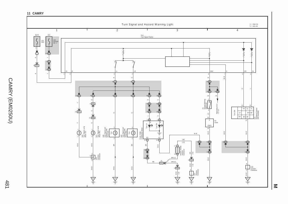
CA
MR
Y (E
M0250U
)481 M
G WW
–BW
–BW
Mai
n B
ody
EC
U<
2–12
>
IF
T u rn S ig n a l a n d H a z a rd W a rn in g L ig h t
3R8
3U2
F1
5
4
3F9
W
3R3
2
F4
7
W–B
10AGAUGENO. 1
R
B
3
9 IL
1 II
W–B
23
S1
S15
GG
12 IP
6 II
W–B
Y
8 IG IG2
B
G
GTu
rn R
H
Turn
LH
2
7 ID
(BAT)
IC3
L G
(IG)
G
15AHAZ
1
W–B
A1
W–B
14
9 3M
3
2
3
2
EN14
R
Y
F1( A
) , F2
( B)
B B
A
W–B
Turn
Turn
A46
A50
12
12
A6
3 421
11 CAMRY
TR EL TL
1513
12
LH
RH
Turn
SW
3F3
W–B
GND1
E
19
20
F3
EA19
3L2
3F1
Y
3G3
W–B
LG
3G8
3P5
3F7
3P7
W–B
9
SN111
Y
SN110
8
G
BR
BR
Turn
Sig
nal a
ndP
arki
ng L
amp
( Fro
nt L
H)
Turn
Sig
nal a
ndP
arki
ng L
amp
( Fro
nt R
H)
Com
bina
tion
Met
er
Clock
Haz
ard
War
ning
Sig
nal S
W
Junc
tion
Con
nect
or
B B
E2ES
A24
41
3Q7
W–B
W–B
GR
BR
A41
( A) ,
A42
( B)
C57
( ∗1)
( ∗1)
( ∗2)
(∗1)
3Q5
3D10
CA34
C6
15EA1
BR GR(∗2)
A17
B18
CA34
BR(∗1)
C7
GR
3
Junc
tion
Con
nect
or
Junc
tion
Con
nect
or
W–B
2
11
2 Turn
Sig
nal L
amp
( Rea
r R
H)
S13
Turn
Sig
nal L
amp
( Rea
r LH
)
S10
W–B
E49
2
9
E2
W–B
3 3C
JunctionConnector
IG B LL LR HAZ E ER EL
6 5
O L
Hea
dlam
p D
imm
erS
W A
ssem
bly
E21
Turn Signal FlasherE14
∗ 2 : 2AZ–FE∗ 1 : 2GR–FE
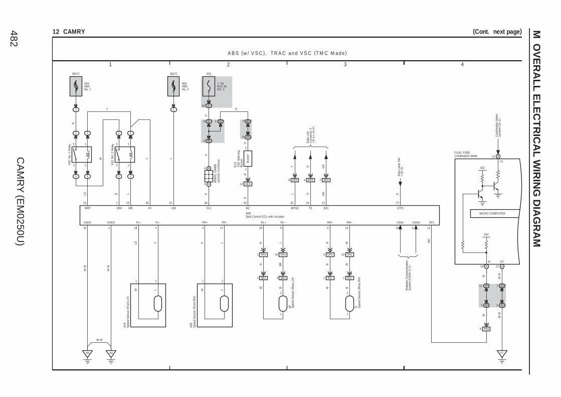
CA
MR
Y (E
M0250U
)482
M O
VE
RA
LL
EL
EC
TR
ICA
L W
IRIN
G D
IAG
RA
M
A B S (w / V S C ), T R A C a n d V S C (T M C M a d e )
L
21
FR+
17
P
3
L
B WR BR
RL–
L
20
R
6
RR–RL+
A4
LW
1
FL+ FR–
W
5
B
W
2
19
RR+GND1
32
GND2
1
W–B
W–B
B
1
(BAT)
L
1
(BAT)
2
+BM
4
LG
18
V
FL–
46
IG1
VS
C N
o. 1
Rel
ay
P
IF19Y
(IG)
GRO
13
D/G
24
TS
7 AE6
O GR
Dat
a Li
nkC
onne
ctor
3<
9–1>
<9–
2>
NA11 NA110 OA11 OA110
3 2
5 1
1 1
1 1
3 2
5 1
1 1
1 1
W
B
15
MR
L
45
R+
Y
14
MRF
LG
Buz
zer
2
1
31
+BS
30
BZ
VS
C N
O. 2
Rel
ay
L
42
WFSE
Y
P
27
Sto
p La
mp
SW
<10
–3>
STP1
CANL CANH SP1
BR
12
E13
50AABSNo. 1
30AABSNo. 2
7. 5AECU IGNO. 2
1125
A14
A35
A26
Mul
tiple
x C
omm
unic
atio
nS
yste
m (
CA
N) <
2–1>
3 421
(Cont. next page)12 CAMRY
3L5 3C5 4D7
3K44A6
RB
O
PO
O
AE614
B4
A3
A6
3D3
3P11
AE64AE68
AE66
WW
A58
( A) ,
E40
( B)
IG2
MICRO COMPUTER
14 B 12 A
3Q7
3U2
F1
W–B
W–B
SI
IG2
E2
F1(A), F2(B)
Spe
ed S
enso
r ( F
ront
LH
)
Skid Control ECU with Actuator
Spe
ed S
enso
r ( F
ront
RH
)
Junc
tion
Con
nect
or
VS
C W
arni
ngB
uzze
r
Combination Meter
gN11 gN12 fO11 fO12B BWW
Spe
ed S
enso
r ( R
ear
LH)
g1 Spe
ed S
enso
r ( R
ear
RH
)f1
1 1
2 2
B12
+S
Com
bina
tion
Met
erS
yste
m<
25–2
>
W–B
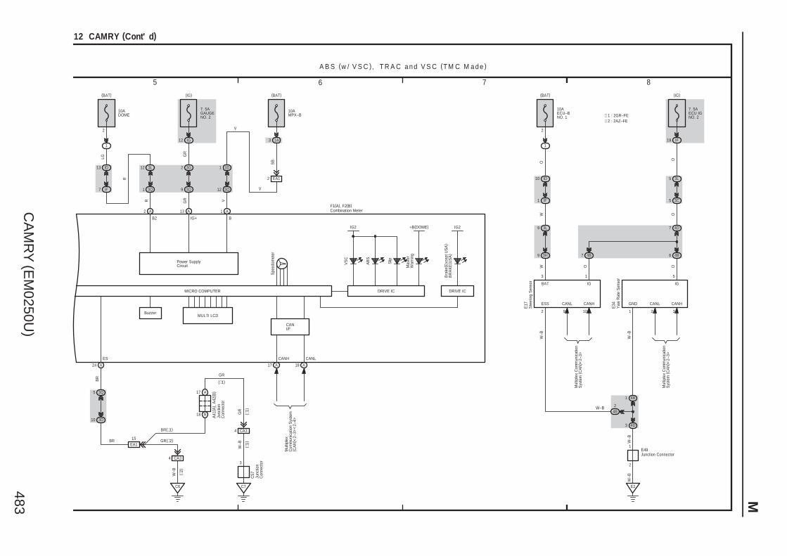
CA
MR
Y (E
M0250U
)483 M
GND
W–B
1
W–B
E2
5
IG
IF19
(IG)
7 4B
O
4B6
3L9
CANL
9
9
1
IG
3
BAT
CANH
10
ESS
2
3H
OW
4D7
5 3C
5 3L
O
2
1 IF
10 ID
1
(BAT)
O
CANL
2
CANH
3
O
A B S (w / V S C ), T R A C a n d V S C (T M C M a d e )
10AECU–BNO. 1
7. 5AECU IGNO. 2
E17
E34
5 6 7 8
12 CAMRY (Cont' d)
W
2
1
4D3
4B1
4B2
Mul
tiple
x C
omm
unic
atio
nS
yste
m (
CA
N) <
2–3>
Mul
tiple
x C
omm
unic
atio
nS
yste
m (
CA
N) <
2–3>
W–B
W–B
E49
W–B
∗ 1 : 2GR–FE∗ 2 : 2AZ–FE
DRIVE IC
IG2
B2 B
Mas
ter
War
ning
Slip
AB
S
VS
C
17 A A18
MULTI LCDBuzzer
Spe
edom
eter
A24
1
VIG+
A
1 3D
12 3Q
1A
10AMPX–B
(BAT)
2
R
R
LG
A
12 3L
1 3Q
13 ID
7 IF
1
10ADOME
(BAT)
2
Power SupplyCircuit
13
GR
GR
A
2 3G
9 3Q
12 IG
7. 5AGAUGENO. 2
(IG)
EA12
V
V
SB
3Q5
3D10
CA34
C6
15EA1
A17
B18
CA34
C7
3
BR
BR(∗1)
GR(∗2)
GR
W–B
W–B
GR
BR
Mul
tiple
xC
omm
unic
atio
n S
yste
m( C
AN
) <2–
3><
2–4>
A41
( A) ,
A42
( B)
C57
( ∗1)
( ∗1)
( ∗2)
(∗1)
ES CANH CANL
F1(A), F2(B)
MICRO COMPUTER
Junc
tion
Con
nect
or
Junc
tion
Con
nect
or
Ste
erin
g S
enso
r
Yaw
Rat
e S
enso
r
Junction Connector
Combination Meter
Bra
ke( E
xcep
t US
A)
BR
AK
E( U
SA
)
IG2
DRIVE IC
3
CANI/F
+B(DOME)
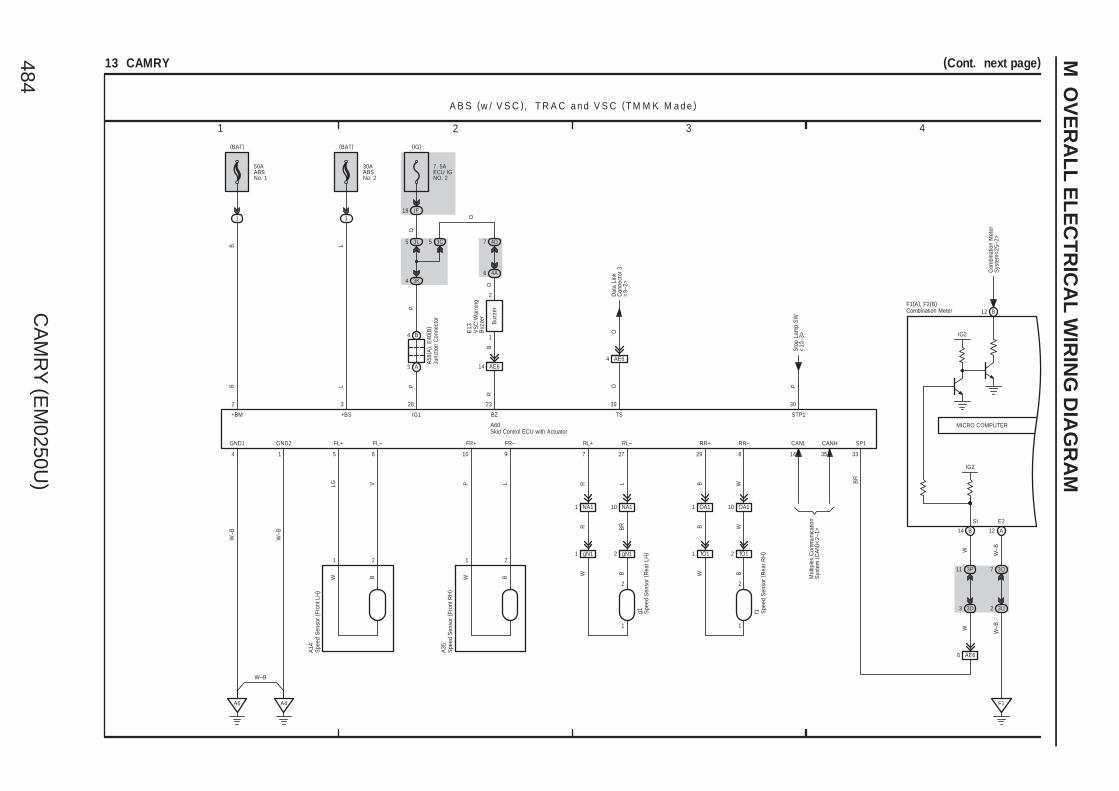
CA
MR
Y (E
M0250U
)484
M O
VE
RA
LL
EL
EC
TR
ICA
L W
IRIN
G D
IAG
RA
M
A B S (w / V S C ), T R A C a n d V S C (T M M K M a d e )
B
21
FR+
9
P
10
L
B WR BR
RL–
L
7
R
27
RR–RL+
A4
BW
1
FL+ FR–
W
29
B
W
2
8
RR+GND1
4
GND2
1
W–B
W–B
B
1
(BAT)
1
(BAT)
2
+BM
6
LG
5
V
FL–
28
IG1P
IF19
(IG)
O
39
TS
O
NA11 NA110 OA11 OA110
B
Buz
zer
2
1
3
+BS
23
BZ
P
30
Sto
p La
mp
SW
<10
–3>
STP1
CANL CANH SP1
BR
33
E13
50AABSNo. 1
30AABSNo. 2
7. 5AECU IGNO. 2
3514
A14
A35
A60
Mul
tiple
x C
omm
unic
atio
nS
yste
m (
CA
N) <
2–1>
3 421
(Cont. next page)13 CAMRY
3L5 3C5 4D7
3K44A6
RB
O
PO
O
AE614
B4
A3
A6
3D3
3P11
AE64
AE66
WW
A58
( A) ,
E40
( B)
LL
MICRO COMPUTER
IG2
14 B 12 A
3Q7
3U2
F1
W–B
W–B
SI E2
F1(A), F2(B)
Spe
ed S
enso
r ( F
ront
LH
)
Spe
ed S
enso
r ( F
ront
RH
)
Junc
tion
Con
nect
orSkid Control ECU with Actuator
VS
C W
arni
ngB
uzze
r
Combination Meter
gN11 gN12 fO11 fO12
B BWW
Spe
ed S
enso
r ( R
ear
LH)
g1 Spe
ed S
enso
r ( R
ear
RH
)f1
1 1
2 2
Dat
a Li
nkC
onne
ctor
3<
9–2>
IG2
B12
Com
bina
tion
Met
erS
yste
m<
25–2
>
W–B

CA
MR
Y (E
M0250U
)485 M
GND
W–B
4
W–B
E2
1
IG
IF19
(IG)
7 4B
O
4B6
3L9
CANL
9
9
1
IG
3
BAT
CANH
10
ESS
2
3H
OW
4D7
5 3C
5 3L
O
2
1 IF
10 ID
1
(BAT)
O
CANL
3
CANH
2
O
A B S (w / V S C ), T R A C a n d V S C (T M M K M a d e )
10AECU–BNO. 1
7. 5AECU IGNO. 2
E17
E65
5 6 7 8
13 CAMRY (Cont' d)
W
2
1
4D3
4B1
4B2
Mul
tiple
x C
omm
unic
atio
nS
yste
m (
CA
N) <
2–3>
Mul
tiple
x C
omm
unic
atio
nS
yste
m (
CA
N) <
2–3>
W–B
W–B
E49
W–B
∗ 1 : 2GR–FE∗ 2 : 2AZ–FE
7. 5AGAUGENO. 2
IG12
3Q9
3G2
A
GR
GR
13
Power SupplyCircuit
2
(BAT)
10ADOME
1
IF7
ID13
3Q1
3L12
A
LG
R
R
2
(BAT)
10AMPX–B
1A
3Q12
3D1
A
IG+V
1
24 A
Spe
edom
eter
BuzzerMULTI LCD
18 AA17
VS
C
AB
S
Slip
Mas
ter
War
ning
BB2
IG2
DRIVE IC
(IG)
EA12
V
V
SB
3Q5
3D10
CA34
C6
15EA1
A17
B18
CA34
C7
3
BR
BR(∗1)
GR(∗2)
GR
W–B
W–B
GR
BR
Mul
tiple
xC
omm
unic
atio
n S
yste
m( C
AN
) <2–
3><
2–4>
A41
( A) ,
A42
( B)
C57
( ∗1)
( ∗1)
( ∗2)
(∗1)
ES CANH CANL
F1(A), F2(B)
MICRO COMPUTER
Junc
tion
Con
nect
or
Junc
tion
Con
nect
or
Ste
erin
g S
enso
r
Yaw
Rat
e S
enso
r
JunctionConnector
Combination Meter
Bra
ke( E
xcep
t US
A)
BR
AK
E( U
SA
)
IG2
DRIVE IC
3
+B(DOME)
CANI/F

CA
MR
Y (E
M0250U
)486
M O
VE
RA
LL
EL
EC
TR
ICA
L W
IRIN
G D
IAG
RA
M
B( ∗
2)
21
FR+
9
P
10
L
B WR BR
RL–
L
7
R
17
RR–RL+
A4
B( ∗
2)
W
1
FL+ FR–
P
W
19
B
W
2
8
RR+
20
GND1
4
GND2
1
W–B
W–B
B
1
(BAT)
L
1
(BAT)
2 3
+BM +BS
6
LG
5
V
FL– SP1
BR
Sto
p La
mp
SW
<10
–3>
OO
18
IG1
P
IF19
(IG)
STP
O
25
TS
O
23
NA11 NA110 OA11 OA110
26
CANH
15
CANL
Mul
tiple
x C
omm
unic
atio
nS
yste
m (
CA
N) <
2–1>
A B S (w /o V S C )
A14
A35
A25
50AABSNo. 1
30AABSNo. 2
7. 5AECU IGNO. 2
A58
( A) ,
E40
( B)
3 421
14 CAMRY
3L5
3K4
A6
∗ 3 : 2GR–FE∗ 4 : 2AZ–FE
AE64
B4
A3
3D3
11
W
IG2
3P
DRIVE IC
(IG)
14 B 12 A
EA12
V
V
SB
3Q7
3U2
F1
W–B
W–B
3Q5
3D10
CA34
C6
15EA1
A17
B18
CA34
C7
3
BR
BR(∗3)
GR(∗4)
GR
W–B
W–B
GR
BR
A41
( A) ,
A42
( B)
C57
( ∗3)
( ∗3)
( ∗4)
(∗3)
SI ES CANH CANLE2
F1(A), F2(B)
6 AE6
W
IG2
MICRO COMPUTER
B2 B
AB
S
17 A A18
Spe
edom
eter
A24
1
V
IG+
A
1 3D
12 3Q
1A
10AMPX–B
(BAT)
2
R
R
LG
A
12 3L
1 3Q
13 ID
7 IF
1
10ADOME
(BAT)
2
Power SupplyCircuit
13
GR
GR
A
2 3G
9 3Q
12 IG
7. 5AGAUGENO. 2
MultiplexCommunication System(CAN)<2–3><2–4>
Spe
ed S
enso
r ( F
ront
LH
)
Skid Control ECU with Actuator
Spe
ed S
enso
r ( F
ront
RH
)
Junc
tion
Con
nect
or
Junc
tion
Con
nect
or
Junc
tion
Con
nect
or
Combination Meter
gN11 gN12 fO11 fO12
B BWW
Spe
ed S
enso
r ( R
ear
LH)
g1 Spe
ed S
enso
r ( R
ear
RH
)f1
L ( ∗1)L ( ∗1)
∗ 1 : TMC Made∗ 2 : TMMK Made
Bra
ke( E
xcep
t US
A)
BR
AK
E( U
SA
)
IG2
DRIVE IC
1 1
2 2
3
Dat
a Li
nk C
onne
ctor
3<
9–2>
CANI/F
IG2
B12
Com
bina
tion
Met
erS
yste
m<
25–2
>
W–B

CA
MR
Y (E
M0250U
)487
Mem
o

CA
MR
Y (E
M0250U
)488
M O
VE
RA
LL
EL
EC
TR
ICA
L W
IRIN
G D
IAG
RA
M
BBD+
B
B
A
–SR+SR
AA
–SL+SL
A
BCL+ BCL–
Y–B Y Y–B Y
SpiralCable
G
A13
ICP–
–SL
C
SFP–SFP+
CB
Y Y–B
Z1
BCR+ BCR–
A28
4
SFD–SFD+
B 7
Y
N21
6A
DK+
A
DK–
B
PD+
7B
PD–
6C
PP+
C
PP– ICD+
B
ICD–
C
ICP+
C
+SL
BBD–
A
D+
A
D–
A
D2+
A
D2–
A
P+
A
P–
A
P2+
A
P2–
B
BBP+
C
BBP–
C
1 2 1 2 1 2 1 2 21
1 2 4 3
2 1 2 1
2 1 2 1
3 4 3
1 2 1 2
DK+ DK–
+SR –SR
BCL+ BCL– BCR+ BCR–
BBR–BBR+BBL–BBL+AE43 AE44 AE42 AE41
Y–B
Y1
E16 c1(A), c2(B)
E54N8 O8
E30(A), N1(B), O1(C)
Y Y–B
Y–B Y Y–B Y
Y–G
Y–RYY–B
R W B G R G RGRGR
BWRG
S R S
9
O7
N7
101095412109
21347865 30 28 29 27 8 15 8 11
O16
N12
O9
3 421
(Cont. next page)15 CAMRY
∗ 1 : 2GR–FE∗ 2 : 2AZ–FE
L+ R+L– R–
D– D2–D+ D2+
P+ P– P2–
ICR–ICL+ ICR+ICL–
Y–B Y
Y–R
Y–G
GR
GR(∗2)
BR(∗1)
BR
3
C7
4 CA3
18 B
17 A
EA115
C6
4 CA3
10 3D
5 3Q
W–B
W–B
F1
2 3U
7 3Q
SB
V
V
2 EA1
A12
(IG)
DRIVE IC
IG2
CANHES
(∗1)
( ∗2)
( ∗1)
( ∗1)
C57
A41
( A) ,
A42
( B)
BR
GR
W–B
W–B
CANLE2
MICRO COMPUTER
B2 B
MultiplexCommunication System(CAN)<2–3><2–4>
SR
S
17 A A18A24
1
V
IG+
A
1 3D
12 3Q
1A
10AMPX–B
(BAT)
2
R
R
LG
A
12 3L
1 3Q
13 ID
7 IF
1
10ADOME
(BAT)
2
Power SupplyCircuit
13
GR
GR
A
2 3G
9 3Q
12 IG
7. 5AGAUGENO. 2
F1( A
)
Airbag Sensor(Front LH)
Airbag Sensor(Front RH)
Junc
tion
Con
nect
or
Junc
tion
Con
nect
or
Airbag Squib(Steering Wheel Pad)
Airbag Sensor Assembly Center
Airbag Squib(Front Passenger' sAirbag Assembly)
Airbag Squib(Knee Airbag)
Com
bina
tion
Met
er
Sid
e A
irbag
Sen
sor
( Rea
r LH
)
Side AirbagSquib (LH)
Curtain ShieldAirbag Squib (LH)
Sid
e A
irbag
Sen
sor
( Fro
nt L
H)
Pretensioner (LH)Curtain ShieldAirbag Squib (RH)
Side Airbag Squib (RH)
Sid
e A
irbag
Sen
sor
( Fro
nt R
H)
Pretensioner (RH)
Sid
e A
irbag
Sen
sor
( Rea
r R
H)
Y Y–B Y Y–B
1 2 1 2
B1 B2 A1 A2
Ec11 Ec12 Ec13 Ec14
Y–G
Y–R
Y–P
Y–G
R
P2+
3
NZ21 NZ22 OY21 OY22
CAN I/F

CA
MR
Y (E
M0250U
)489 M
3 IM
1 IE
A
E2
A
A
PAONP–AB
Dat
a Li
nk C
onne
ctor
3<
9–2>
A
A
E1
R B
SIL
IH10
IE6
IH12
IE4
IE5
IF10
E2E1
WW
–B
W–B
W–B
231716
2526 B
DSP+DBE–
B B
SVC2SGD1
BB
DBE+
T17(A), d5(B)
B
DD
SVC4
D
SIG1SVC1
D
B( ∗
3)
N3
R
P( ∗
3)
G OLW
( ∗3)
( ∗3) SVC3 SIG3 SGD3
Seat PositionAirbag Sensor
Dat
a Li
nkC
onne
ctor
3<
9–2>
SIG4
SVC1
BR
GR
GR
O
B
DSP–
A
DIA
B
SIG3
B
SGD3
B
SGD4
SIG2
D
SGD2
D
1 3 2 4
SVC3
SIG1 SGD1 SVC2 SIG2 SGD2
SVC4 SIG4 SGD4
EO24
T15(A), d3(B)
T14(A), d2(B) T16(A), d4(B)
O4(C), T10(A), T11(B), d1(D)E30(A), N1(B), O1(C)BWRG
VWYGR
∗ 4 : w/o Power Seat∗ 3 : w/ Power SeatS R S
13141211
11 7 1 12 8 2
2 5 9 3 6 10 4
5 6 7 8
15 CAMRY (Cont' d)
9 A
W–B
(∗4)(∗3)
C3
7C
2 EO2
2
IH
1
2
A
FSR–FSR+
C
BSW
W–B
1 A
L
B( ∗
3)
( ∗3)
( ∗4)
A
IG2
8C
FSP–
C
FSP+
4
GND BGND
C
IG
C
+B
2 B 1 B
W
EO23
(IG)
IE9
B
B
(BAT)
1
2
ID10
IF1
W O
O3(B), T7(A)
W( ∗
3)
Y BR W
BR
LG( ∗3)
( ∗3)
( ∗3)
( ∗3)
( ∗3)
( ∗3)
GRB ( ∗3)
3C10
3L9
W
10AIGN
10AECU–BNO. 1
121321
A
B(∗4)
B(∗3)
LG
W(∗4)
W(∗3)
(∗3)A5(∗4)C5
P( ∗
4)
3
( ∗4)
C9
(∗4)
O( ∗
4)
A8 A4 A7 (∗3)A1
BR
( ∗4)
C2
A13 A22
Mul
tiple
x C
omm
unic
atio
nS
yste
m (
CA
N) <
2–3>
CANH CANL
3R6 3R5
3E8 3D9
R B
R B
2
10
W–B
E49
W–B
LBE+ LBE– LSP+ LSP–
B ( ∗3)
B3
A5
O1
3
O20
( A) ,
T18(
B)
14 13
P–AB PAON
F3
Airbag Sensor Assembly Center
Junc
tion
Con
nect
or
Clock
Front Seat Inner Belt (Driver' s Side)Ju
nctio
n C
onne
ctor
Occupant Classification ECU
Occupant ClassificationSensor (Front LH)
Occupant ClassificationSensor (Rear LH)
Occupant ClassificationSensor (Front RH)
Occupant ClassificationSensor (Rear RH)
Front Seat Inner Belt(Front Passenger' s Side)
(∗3)B2
(∗3)A3(∗4)B3
(∗3)A3(∗4)B3
A1B1
A2B2
A1B1
A2B2
B8B12B1B7B11
SB
( ∗4)
(∗4)
D5 D9 D3 D6 D10 (∗4)D4
R( ∗
4)
B1 B2 B3 B1 B2A2
(∗4)B3(∗3)A3A1 A2 (∗3)A3 A1
(∗3)
(∗4)
OT11 OT14 OT16 OT15
AIRBAG ON/OFFIndicator
Junc
tion
Con
nect
orO
21
EO210
E3
( ∗3)
W–B
( ∗3)
W–B
Buckle SW
OT12
Buckle SW
E3
W–B
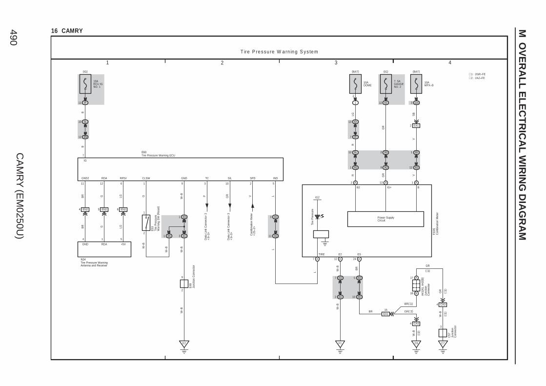
CA
MR
Y (E
M0250U
)490
M O
VE
RA
LL
EL
EC
TR
ICA
L W
IRIN
G D
IAG
RA
M
1 2 3 4
16 CAMRY
10AECU IGNO. 1
IF11
(IG)
3L10
3N12
BB
IG
7
EN24 EN25 EN26
3O1
3C3
W–B
E2
Dat
a Li
nk C
onne
ctor
3<
9–3> Com
bina
tion
Met
er<
25–2
>
Dat
a Li
nk C
onne
ctor
3<
9–3>
BR G LG P GR V L
BR G LG
W–B
GND2 RDA RF5V GND TC SIL SPD IND
11 12 6 9 3 10 2 5
GND RDA +5V
E60
N34
3O3
3Q11
L
T ire P re s s u re W a rn in g S y s te m
2
1
O
CLSW
1
E53
3N1
W–B
W–B
2
9
E49
W–B
∗ 1 : 2GR–FE∗ 2 : 2AZ–FE
A
12 3L
1 3Q
13 ID
7 IF
1
10ADOME
(BAT)
2
Power SupplyCircuit
13
GR
GR
A
2 3G
9 3Q
12 IG
7. 5AGAUGENO. 2
LGR
2
(BAT)
10AMPX–B
1A
3Q12
3D1
A
IG+
V
1
24 A
BB2
E2
W–B
W–B
GR
BR
A41
( A) ,
A42
( B)
C57
( ∗1)
( ∗1)
( ∗2)
(∗1)
IG2
(IG)
12 A
EA12
SB
3Q7
3U2
F1
W–B
W–B
3Q5
3D10
CA34
C6
15EA1
A17
B18
CA34
C7
3
BR
BR(∗1)
GR(∗2)
GR
F1( A
)
A7
Tire
Pre
ssur
e
TIRE ES
L
R
V
Junc
tion
Con
nect
or
Junc
tion
Con
nect
or
Junc
tion
Con
nect
or
Tire
Pre
ssur
eW
arni
ng S
W (
Res
et)
Tire Pressure Warning ECU
Com
bina
tion
Met
er
Tire Pressure WarningAntenna and Receiver
4 1 5
3

CA
MR
Y (E
M0250U
)491 M
1 2 3 4
17 CAMRY
1
V
2
P LG
5
206
F4
5
ERSETA/BILL+GND1
ACCB
10ADOME
2
1
(BAT)
ID13
IF7
3L12
3R1
3L11
3R2
7. 5AECU–ACC
(ACC)
IF2
1 2
3R8
3U2
F1
W–B
19 4
LG
LLR
W–B O
R
Mai
n B
ody
EC
U<
2–11
>
C lo c k
CLS
12
W–B
W–B
6 EQ1
IG
4
E
1
10AECU IGNO. 1
IR10
W–B
Y
A u to m a ticG la re – R e s is ta n tE C M irro r
Q3
S lid in g R o o f
30AS/ROOF
IR12
EQ110 EQ18
Mai
n B
ody
EC
U<
2–33
>
B P
Q13
UP DWN CLS OPN
(IG)
11 EQ1
Y
Q6
W–B
W–B
IR1
IF10
W–B
2
10
E2
W–B
W–B
F1
DOWN
Y
UP OPN
2145
E
B MPX1 IG
E49
Junc
tion
Con
nect
or
Hazard Warning Signal SW
Inne
r R
ear
Vie
w M
irror
Ove
rhea
d J/
B
Sliding Roof Control ECU and Motor
(BAT)
ClockF3
M
Y
W–B
A/B RSET E
GND
3
W–B
4FE3
MICRO COMPUTER
B2 B
MULTI LCD
1
V
IG+
A
1 3D
12 3Q
1A
10AMPX–B
(BAT)
2
R
R
LG
A
12 3L
1 3Q
13 ID
7 IF
1
10ADOME
(BAT)
2
Power SupplyCircuit
13
GR
GR
A
2 3G
9 3Q
12 IG
7. 5AGAUGENO. 2
(IG)
12 A
EA12
V
V
SB
3Q7
3U2
F1
W–B
W–B
3
E2
P YB
10 8 9 7 2
1 4 5
W G L BR
W–B
Sliding Roof Control SW
A24
3Q5
3D10
CA34
C6
15EA1
A17
B18
CA34
C7
3
BR
BR(∗1)
GR(∗2)
GR
W–B
W–B
GR
BR
A41
( A) ,
A42
( B)
C57
( ∗1)
( ∗1)
( ∗2)
(∗1)
Junc
tion
Con
nect
or
Junc
tion
Con
nect
or
ES
Combination MeterF1(A)
Mas
ter
War
ning
+B(DOME)
DRIVE IC
∗ 1 : 2GR–FE∗ 2 : 2AZ–FE
Buzzer

CA
MR
Y (E
M0250U
)492
M O
VE
RA
LL
EL
EC
TR
ICA
L W
IRIN
G D
IAG
RA
M
1 2 3 4
18 CAMRY
(BAT)
50ARR DEF
10AMIR HTR
1
IO13 IK1
1
IE210 HE210
IE217 HE217
E2
N19
( A) ,
P1(
B)
I3 H2
YY
B Y Y
W–B
W–B
W–B
4 4
3 3
B
L
LG
21 IE222 IE220 IE2
11 3I
(ACC)
7635 2 4
EM+MLVMLH MRH MRV
RightLeftLeft Right
8
E2
7. 5AECU–ACC
IF2
L
M
I3
M
HE222
H2
HE220 HE221
MM
215251
MH MV
W–B
B
M+
VBR
E3
MV MH
W–BB
M+
VBR
BWLG
W–BBBRWV
B
W
11 3L
3I33I2
3I1 3C3
3G1
R e a r W in d o w D e fo g g e r a n d M irro r H e a te rR e m o te C o n tro l M irro r
B
Left
Rig
ht
Up
Dow
n
Left/
Up
Rig
ht/
Dow
n
2
9
IJ12
A1
B1
P1
W–B
EA15
3D12
3M6
A/C
Am
plifi
er<
27–6
>G
G
10AA/CNO. 2
ID12
A22
B14
G
V
( 2G
R–F
E)
V
( 2G
R–F
E)
V
( 2A
Z–FE
)
1 5
2 3
RRDEFRelay
4
W
W
2
13W–B5
E49
Y
(IG)
1
2
E49
W–B
1
1
1
IB2
1W–B
A1
Ope
ratio
n S
WS
elec
t SW
N18
Outer Mirror SW
JunctionConnector
Junction Connector
Outer Rear View Mirror (RH)
Out
er R
ear
Vie
w M
irror
(R
H)
Outer Rear View Mirror (LH)
Out
er R
ear
Vie
w M
irror
(LH
)
Noi
se F
ilter
( Rea
r W
indo
w D
efog
ger)
Rea
r W
indo
wD
efog
ger
Junc
tion
Con
nect
or
A41
( A) ,
A42
( B)
Mirr
orH
eate
r
Mirr
orH
eate
r
A3
W–B
W–B
W–B

CA
MR
Y (E
M0250U
)493 M
1 2 3 4
19 CAMRY
IC12
12M
10AWASH
B1
2
(IG)
IC
LO
A3
2 II
AE21725 AE2
3A
Wiper Relay
MIS
T
OFF INT
E2
3
M
+1
E
+SB
2A
1B
25AWIP
B
2B
4B
HI
(IG)
B
L
LG( ∗
1)
GR
W–B
W
P
G
LP
( ∗1)
BR
( ∗1)
LG( ∗
1)
B( ∗
1)
W–B
P W
EW
WF
+S
+1
+B
+2
INT1
INT2
+S+1
+2+B
A37
A59(B), B1(A)
Front Wiper SW
EW
On
Off
W
FrontWasher SW
E19(A), E20(B)
EO220 EN220
20AS–HTR
IM19
(IG)
A8
B6
3 6
5
BL P
P
N27
( A) ,
U11
( B)
E55
E2
4
W–B
W–B
IG
RH E LH
RH
Sid
eS
eat S
W
LH S
ide
Sea
t SW
B2
A5
B8
A11
AB13
P( ∗
1)
AB15 AB12 AB11
A58(A), E40(B)
A58
( A) ,
E40
( B)
BR
( ∗1)
LG( ∗
1)
B( ∗
1)
W–B
W–B
2
7
A8
B6
L
O20
( A) ,
T18(
B)
E49
W ip e r a n d W a s h e r S e a t H e a te r
WindshieldWasher Motor
JunctionConnector
Junc
tion
Con
nect
or
WindshieldWiper Motor
Windshield Wiper SW Assembly
Junc
tion
Con
nect
or
Sea
t Hea
ter
SW
Junc
tion
Con
nect
or
Junc
tion
Con
nect
or
Sea
tB
ack
Sea
tC
ushi
on
Sea
tB
ack
Sea
tC
ushi
on
1
P
A5
B1EN210
E3
A5
B110
EO2
R
1
L
2 2
W–B
W–B
W–B
W–B
W–B
W–B
W–B
JunctionConnector
O20(A), T18(B)
Sea
t Hea
ter
( RH
)T6 S
eat H
eate
r ( L
H)
U6
Junc
tion
Con
nect
or
N27
( A) ,
U11
( B)
4AB1
A4B4
(∗1)(∗2)
B3A3
B5A5
B2A2
(∗2)B1(∗1)A1
LG( ∗
2)
P( ∗
2) BR
( ∗2)
B( ∗
2)
LG( ∗
2)
(∗1)
( ∗1)
W–B(∗2)
∗ 2 : TMMK Made∗ 1 : TMC Made
+2
A2
W–B
O1
EO19
W–B
W–B

CA
MR
Y (E
M0250U
)494
M O
VE
RA
LL
EL
EC
TR
ICA
L W
IRIN
G D
IAG
RA
M
4
SlideFrontVertical Reclining Lifter
Dow
n
Up
Rea
r
Fron
t
Dow
n
Up
Rea
r
Fron
tL G P W VBRBY
M
2
1
M
2
1
M
1
2
1
2
1
U4
9 6 10 5
U3
3 2 7 8U
2
U1
LG
M
LG
W–B
W–BW
W–B
YLG
E2
B
A
U5
U8
B
A
2
(BAT)
4 IO
30AP/SEAT
1
2
M
Rea
r
Fron
t
4
Slide Reclining
Rea
r
Fron
t
Rea
r
Fron
t
T1
1
2369
1
2
M
1
2
L Y P BR
T3
W–B
W–B
T8
M
EO21
EO210
W–B
P o w e r S e a t (D r iv e r ' s S e a t) P o w e r S e a t (F ro n t P a s s e n g e r ' s S e a t)
6
2
5
9
3 421
20 CAMRY
IL11
N27(A), U11(B)
B8
LG
E H R R1
B4B3
W–B
W–B
N27(A), U11(B)
EN210
W–B
B
SLDR FDWN RCLR LDWNLUPRCLFFUPSLDFE
W–B
A6
B8
GG
B
ERCLFSLDF SLDR RCLR
B4
A5
E3
O20(A), T18(B)
G G
O20(A), T18(B)
JunctionConnector
JunctionConnector
JunctionConnector
JunctionConnector
Pow
er S
eat M
otor
( Fro
nt P
asse
nger
's
Sea
t Slid
e C
ontro
l)
Pow
er S
eat M
otor
( Fro
nt P
asse
nger
's
Sea
t Rec
linin
g C
ontro
l)
Power Seat SW (Front Passenger' s Seat)
Pow
er S
eat M
otor
( Driv
er'
s S
eat
Slid
e C
ontro
l)
Pow
er S
eat M
otor
( Driv
er'
s S
eat
Fron
t Ver
tical
Con
trol)
Pow
er S
eat M
otor
( Driv
er'
s S
eat
Rec
linin
g C
ontro
l)
Pow
er S
eat M
otor
( Driv
er'
s S
eat
Lifte
r C
ontro
l)
Pow
er S
eat M
otor
( Driv
er'
s S
eat L
umba
rS
uppo
rt C
ontro
l)
Pow
er S
eat S
W( D
river
's
Sea
t Lum
bar
Sup
port
Con
trol)
Power Seat SW (Driver' s Seat)U7
5 4 1 2
3
B

CA
MR
Y (E
M0250U
)495 M
1 2 3 4
21 CAMRY
20APWR OUTLET
IO12
(ACC)
IM16
2
8
E2
4
EN211
R R
R R
W–B
W–B
W–B
2 2
1 1
E E
B B
E35
E29
E49
FL MAIN3. 0W
Battery
10AHORN
10 1D 1B6
II5
ID11
W
A411
A3
B
B
GR
HORNRelay
1G1
H o rnP o w e r O u tle t
W
W
Horn (High)Horn (Low)
Pow
er O
utle
tS
ocke
t (Fr
ont)
Pow
er O
utle
tS
ocke
t (R
ear)
Junc
tion
Con
nect
or
Mai
n B
ody
EC
U<
2–11
>
A8
HO
B1
LH
orn
SW
SteeringPad SW
a1(B)
Spiral CableE18(A), a1(B)
W–B
E49
2
9
5 B (∗2)1 B3 A
E2
W–B
3 3C
Mai
n B
ody
EC
U<
2–11
>
(IG)
G
19 IF
O
5 3K
5 3L
SLS–SLS+
O
IG
Shift LockSolenoid
P2
( ∗2)
KLS+
W–B
( ∗2)
E32(B), E57(A)
Y ( ∗2)
W–B
E
3K13K2
11 3K
11 3L
L
ACC
(ACC)
2 IF
L ( ∗2)
( ∗1)
Sto
p La
mp
SW
<10
–3>
W
STP
7. 5AECU IGNO. 2
7. 5AECU–ACC
(∗1)
B8A12
B6A11
(∗2)B4(∗1)A6
Shift Lock Control ECU
JunctionConnector
Key
Inte
rlock
Sol
enoi
d
E24
2
1
P E2
S h ift L o c k
∗ 1 : w/ Smart Key System∗ 2 : w/o Smart Key System
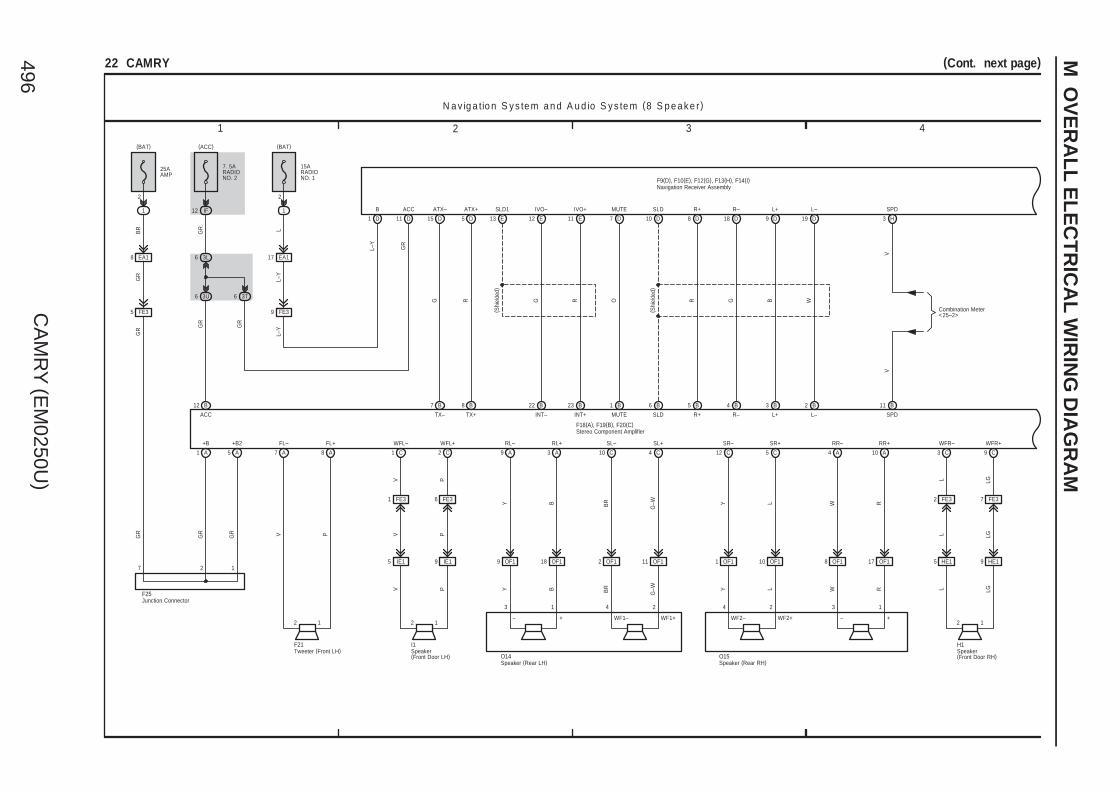
CA
MR
Y (E
M0250U
)496
M O
VE
RA
LL
EL
EC
TR
ICA
L W
IRIN
G D
IAG
RA
M
1 2 3 4
22 CAMRY (Cont. next page)
N a v ig a tio n S y s te m a n d A u d io S y s te m (8 S p e a k e r)
7. 5ARADIONO. 2
IF12
(ACC)
15ARADIONO. 1
1
(BAT)
25AAMP
1
(BAT)
EA18 EA1173L6
3U6 3T6
IE15 IE19
LL–
Y
L–Y
BR
GR
GR
GR
GR
GR
A1 A5
7 2 1
F25
GR
GR
GR
GR
B12
D1 D11 D15 D5 E13 E12 E11 D7 D10 D8 D18 D9 D19 H3
B7 B8 B22 B23 B1 B5 B4 B3 B2 B11
C1 C2A7 A8 A9 A3 C10 C4 C12 C5 A4 A10
B ACC ATX– ATX+ SLD1 IVO– IVO+ MUTE SLD R+ R– L+ L– SPD
+B +B2 WFL– WFL+FL– FL+ RL– RL+ SL– SL+ SR– SR+ RR– RR+
ACC TX– TX+ INT– INT+ MUTE R+ R– L+ L– SPD
G R
( Shi
elde
d)
G R O
( Shi
elde
d)
R G B W
V
V P
V P
V P
V P
Y B BR
G–W Y L W R
B6
SLD
Combination Meter<25–2>
V
OF19 OF118 OF12 OF111
3 1 4 2
Y B BR
G–W
O14
OF11 OF110 OF18 OF117
Y L W R
4 2 3 1
O15
HE15 HE19
C3 C9
WFR– WFR+
L LG
L LG
L LG
L–Y
F9(D), F10(E), F12(G), F13(H), F14(I)
F18(A), F19(B), F20(C)
2 1 2 1
I1F21
2 1
H1
Stereo Component Amplifier
Tweeter (Front LH)
Junction Connector
Navigation Receiver Assembly
Speaker(Front Door RH)
Speaker(Front Door LH)
Speaker (Rear LH) Speaker (Rear RH)
2 2
FE35 FE39
FE31 FE36 FE32 FE37
– + WF1– WF1+ WF2– WF2+ – +

CA
MR
Y (E
M0250U
)497 M
7 865
22 CAMRY (Cont' d)
3U8
3D7
3T1
3A1
3T12
3A10
3T8
3A8
F3
C7 C6
BR
BR
E GND
GNDTSW– SGND VAL+ VAR+ VA– ADPGANT SWGSW1 SW2
G12 G18 I3 I2 I5 I6D13 E6E7 E8 D20
BR
YO PRR PO Y
O
1
B
F15
F17
1 2 3 4
R G G
ALO ARO ASGN AUXO
BR
BR
( Shi
elde
d)
5 H
REV
P
FE27 FE28 FE29 FE210
EQ112 EQ13 EQ12 EQ11
F2
A6 A2
FR– FR+
L LG
G17
MACC
G19
MIC+
G9
MIC–
LG G R
( Shi
elde
d)
W–B
LG G R
LG G R
ACC MI1+ MIC–
Q5(A), Q12(B)
( Shi
elde
d)( S
hiel
ded)
W–B
N a v ig a tio n S y s te m a n d A u d io S y s te m (8 S p e a k e r)
F18(A), F19(B), F20(C)
F9(D), F10(E), F12(G), F13(H), F14(I)
BR
2 1
F23
Antenna Amplifier
Stereo Jack Adapter
Stereo Component Amplifier
Tweeter (Front RH)
Navigation Receiver Assembly
Microphone (Navigation)
A6 A4 A5
AU1 EAU
B10 B8 B9
Seek–
Volume+
Volume–
MODESeek+
Ste
erin
g S
W L
H
AU2
Voice
On Hook
Off Hook
Ste
erin
g S
W R
H
W B G
Steering Pad SWa1(B)
Spiral CableE18(A), a1(B)
Par
k/N
eutra
l Pos
ition
SW
<10
–1>
B1A1
B3A3
(∗2)B5(∗1)A5
∗ 2 : TMMK Made∗ 1 : TMC Made

CA
MR
Y (E
M0250U
)498
M O
VE
RA
LL
EL
EC
TR
ICA
L W
IRIN
G D
IAG
RA
M
1 2 3 4
23 CAMRY (Cont. next page)
A u d io S y s te m (8 S p e a k e r w /o N a v ig a tio n S y s te m )
7. 5ARADIONO. 2
IF12
(ACC)
15ARADIONO. 1
1
(BAT)
25AAMP
1
(BAT)
EA18 EA1173L6
3U6 3T6
IE15 IE19
LL–
Y
L
BR
GR
GR
GR
GR
GR
A1 A5
7 2 1
F25
GR
GR
GR
L–Y
B12
F5 D1 D15 D5 D7 D10 D8 D18 D9 D19
B7 B8 B1 B5 B4 B3 B2 B11
C1 C2A7 A8 A9 A3 C10 C4 C12 C5 A4 A10
+B B ATX– ATX+ MUTE SLD R+ R– L+ L–
+B +B2 WFL– WFL+FL– FL+ RL– RL+ SL– SL+ SR– SR+ RR– RR+
ACC TX– TX+ MUTE R+ R– L+ L– SPD
G R O
( Shi
elde
d)
R G B W
V P
V P
V P
V P
Y B BR
G–W Y L W R
B6
SLD
V
ANT
D13
O
1
B
F15
OF19 OF118 OF12 OF111
3 1 4 2
Y B BR
G–W
O14
OF11 OF110 OF18 OF117
Y L W R
4 2 3 1
O15
HE15 HE19
C3 C9
WFR– WFR+
L LG
L LG
L LG
L–Y
F8(C), F11(F), F26(D)
F18(A), F19(B), F20(C)
11 D
GR
ACC ACC
GR
F16
5
12
9
13 10 11
F25
L–Y
GR
Com
bina
tion
Met
er<
25–2
>
2 1 2 1
I1F21
2 1
H1
AntennaAmplifier
Stereo Component Amplifier
Tweeter (Front LH)
JunctionConnector
Junction Connector
Radio Receiver Assembly
Speaker(Front Door RH)
Speaker(Front Door LH)
Speaker (Rear LH) Speaker (Rear RH)
2 2
FE35 FE39
FE31 FE36 FE32 FE37
11 C12 C13 C
B22 23 B
SLD IVO– IVO+
INT– INT+
( Shi
elde
d)
G R
– + WF1– WF1+ WF2– WF2+ – +

CA
MR
Y (E
M0250U
)499 M
7 865
23 CAMRY (Cont' d)
F2F3
C7 C6
BR
BR
E GND
GNDALI ARI ASGN AUXI
C17 C15 C16 C19 F14
BR
F17
1 2 3 4
R G G
ALO ARO ASGN AUXO
BR
BR
( Shi
elde
d)
FE27 FE28 FE29 FE210
F2
A6 A2
FR– FR+
L LG
F7
MCVD
F2
MIC+
F1
MIC–
LG G R
( Shi
elde
d)
W–B
LG G R
( Shi
elde
d)
W–B
A u d io S y s te m (8 S p e a k e r w /o N a v ig a tio n S y s te m )
F18(A), F19(B), F20(C)
F8(C), F11(F), F26(D)
BR
BR
20 D
GND
BR
2 1
F23
Stereo Jack Adapter
Stereo Component Amplifier
Tweeter(Front RH)
Radio Receiver Assembly
3T1
3A1
3T12
3A10
3T8
3A8
YO PPO Y
C87 C 6 C
SW2SW1 SWG
A6 A4 A5
AU1 EAU
B10
E18(A), a1(B)Spiral Cable
B8 B9
a1(B)Steering Pad SW
Seek–
Volume+
Volume–
MODESeek+S
teer
ing
SW
LH
AU2
Voice
On Hook
Off Hook
GBW
Ste
erin
g S
W R
H
EQ112 EQ13 EQ12 EQ11
LG G R
ACC MI1+ MIC–
Q5(A), Q12(B)
( Shi
elde
d)
Microphone (Navigation)
B1A1
B3A3
(∗2)B5(∗1)A5
∗ 1 : TMC Made∗ 2 : TMMK Made
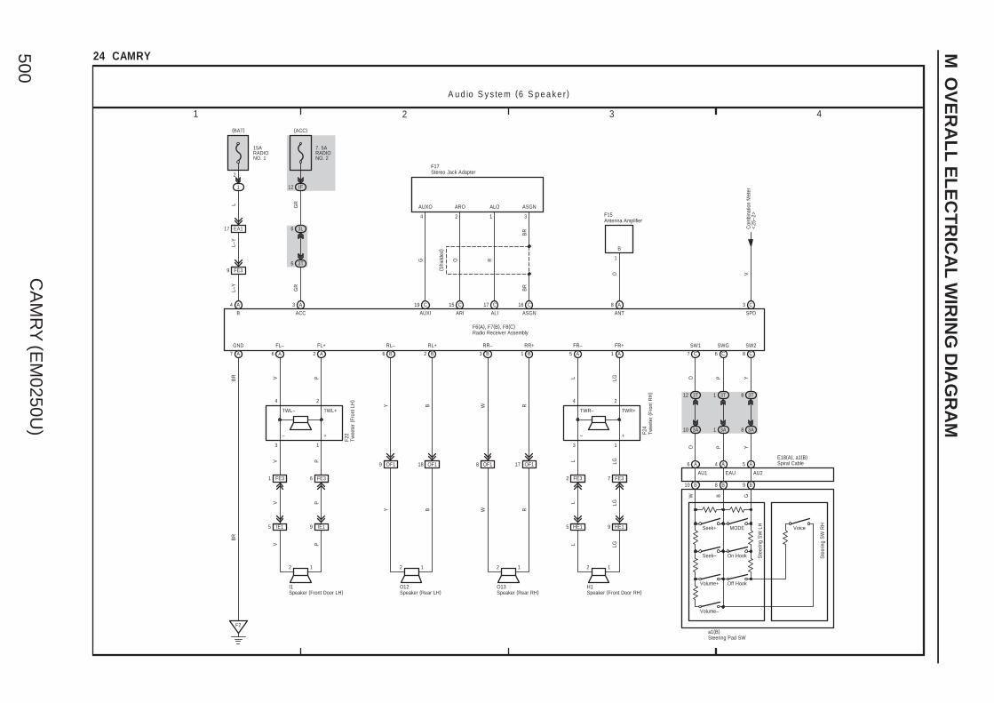
CA
MR
Y (E
M0250U
)500
M O
VE
RA
LL
EL
EC
TR
ICA
L W
IRIN
G D
IAG
RA
M
1 2 3 4
24 CAMRY
15ARADIONO. 1
1
(BAT)
7. 5ARADIONO. 2
IF12
(ACC)
EA117 3L6
3T6
F2
IE19IE15
OF19 OF118 OF18 OF117
HE15 HE19
A u d io S y s te m (6 S p e a k e r)
A4 A3 C19 C15 C17 C16 C3
A7 A6 A2 B6 B2 B3 B1 A5 A1
LL–
YL–
Y
GR
GR
B ACC
BR
AUXI ARI ALI ASGN
AUXO ARO ALO ASGN
G O R
F17
4 2 1 3
BR
BR
( Shi
elde
d)
VC
ombi
natio
n M
eter
<25
–2>
SPD
GND FL– FL+ RL– RL+ RR– RR+ FR– FR+
V P L LG
PV L LG
L LGV PPV L LG
Y B W R
Y B W R
F22 F2
4
4 2 4 2
13 3 1
BR
F6(A), F7(B), F8(C)
2 1 2 1
I1 O12
2 1 2 1
H1O13
Stereo Jack Adapter
Twee
ter
( Fro
nt L
H)
Twee
ter
( Fro
nt R
H)
Radio Receiver Assembly
Speaker (Front Door RH)Speaker (Front Door LH) Speaker (Rear LH) Speaker (Rear RH)
A8
O
ANT
B
1
Antenna AmplifierF15
3T1
3A1
3T12
3A10
3T8
3A8
YO PPO Y
C87 C 6 C
SW2SW1 SWG
A6 A4 A5
AU1 EAU
B10
E18(A), a1(B)Spiral Cable
B8 B9
a1(B)Steering Pad SW
Seek–
Volume+
Volume–
MODESeek+
Ste
erin
g S
W L
H
AU2
Voice
On Hook
Off Hook
GBW
Ste
erin
g S
W R
H
2
TWL– TWL+
– +
TWR– TWR+
– +
FE39
FE32 FE37FE36FE31

CA
MR
Y (E
M0250U
)501
Mem
o

CA
MR
Y (E
M0250U
)502
M O
VE
RA
LL
EL
EC
TR
ICA
L W
IRIN
G D
IAG
RA
M
1 2 3 4
25 CAMRY (Cont. next page)
(∗1)
( ∗2)
( ∗1)
( ∗1)
C57
A41
( A) ,
A42
( B)
Mul
tiple
xC
omm
unic
atio
n S
yste
m( C
AN
) <2–
3><
2–4>
BR
GR
W–B
W–B
GR
GR(∗2)
BR(∗1)
BR
3
C7
4 CA3
18 B
17 A
EA115
C6
4 CA3
10 3D
5 3Q
10 3N
2 3P
7 3O
6 3P
AB
S (
w/o
VS
C)
Sys
tem
<14
–3>
AB
S (
w/ V
SC
) , T
RA
Can
d V
SC
Sys
tem
<12
–4>
<13
–4>
W–B
W–B
F1
2 3U
7 3Q
SB
V
V
2 EA1
A41
( A)
L
V
VG
Eng
ine
Con
trol
Mod
ule<
7–19
>
Tran
smis
sion
Con
trol E
CU
<7–
24>
14 AE5
3 3P
10 3B
A6 5 A7 A
V
Illum
inat
ion
Poi
nter
Illum
inat
ion
LCD
Illum
inat
ion
A12
Turn
RH
Turn
LH
BB 12
Turn
Sig
nal a
ndH
azar
d W
arni
ngLi
ght S
yste
m<
11–3
>
B14
B12
(IG)
7. 5AGAUGENO. 2
IG12
3Q9
3G2
A
GR
GR
13
Power SupplyCircuit
2
(BAT)
10ADOME
1
IF7
ID13
3Q1
3L12
A
LG
R
R
2
(BAT)
10AMPX–B
1A
3Q12
3D1
A
V
1
B15 24
2
3
14 EN2 EN215
BG
R P
GR P
GR P
N10
16 A
Gag
e
9 A
Spe
edom
eter
Tach
omet
er
Fuel
Tem
p. Buzzer LCD
A/T Range
18
LCD(ODO/Trip)(Outside Temp. )
AA17
C o m b in a tio n M e te r
BIG+B2+SB B
11 A
ILL–
Mul
tiple
xC
omm
unic
atio
nS
yste
m (
CA
N)
<2–
15>
E2 SI FR FE ES P/SB CANH CANL
A22
3A6
3Q6
VV
V
∗ 1 : 2GR–FE∗ 2 : 2AZ–FE
L ( ∗1)
( ∗1)
+B(DOME)IG2
+B(DOME)IG2
IG2
+B(DOME)
+B(DOME)IG2+IG2
MICRO COMPUTER
+B(DOME)IG2
F1(A), F2(B)
Air
Con
ditio
ning
Sys
tem
<27
–7>
Junc
tion
Con
nect
or
Junc
tion
Con
nect
or
Junc
tion
Con
nect
or
Combination Meter
Fuel
Suc
tion
Pum
pan
d G
age
Ass
embl
y
∗ 3 : w/ Smart Key System∗ 4 : 8 Speaker∗ 5 : 6 Speaker
L ( ∗2)
Eng
ine
Con
trol
Mod
ule<
8–11
>
L
(∗2)
3M10 3O10 3T9
Mai
n B
ody
EC
U<
2–11
>
Tire
Pre
ssur
eW
arni
ng E
CU
<16
–2>
Rad
io R
ecei
ver
Ass
embl
y<24
–4>
V ( ∗3) V V ( ∗5)
3U10 3U9
Nav
igat
ion
Rec
eive
rA
ssem
bly<
22–4
>
V
Ste
reo
Com
pone
ntA
mpl
ifier
<22
–4>
<23
–4>
V ( ∗4)
Mul
tiple
xC
omm
unic
atio
nS
yste
m (
CA
N)
<2–
14>
A3 A9
B7 B2
DIS
P
Ste
erin
g S
W R
HY GR
+DP EAC
Spi
ral C
able
E18
( A) ,
a1( B
)S
teer
ing
Pad
SW
a1( B
)
3
RheostatTail Cancel SWODO/Trip SW
CANI/F
MULTI LCD
DISP
( ∗1)
( ∗1)
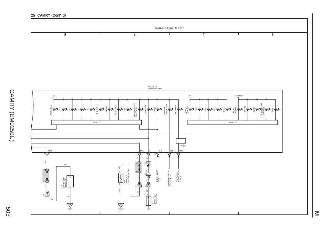
CA
MR
Y (E
M0250U
)503 M
7 865
25 CAMRY (Cont' d)
F1(A), F2(B)
P R N D
S, 4
, 3, 2
, L
Low
Fue
l
Cha
rge
MA
INT
RE
QD
23 A6 B 8 A
Bra
ke( E
xcep
t US
A)
BR
AK
E( U
SA
)
Mal
func
tion
Indi
cato
r La
mp
Tire
Pre
ssur
e
4 B 7 A
Driv
er'
sS
eat B
elt
VS
C
AB
S
Slip
Cru
ise
DO
OR
Mas
ter
War
ning
Fron
t Fog
Tail
( Exc
ept U
SA
)H
ead
( US
A)
Bea
m
Cha
rgin
g S
yste
m<
4–4>
Eng
ine
Con
trol S
yste
m<
7–25
><
8–18
>
Tire
Pre
ssur
eW
arni
ng S
yste
m<
16–3
>
6 3E
8 3P
AE632
1
A3
CA36
1
LG O
LGLG
LGW
–B LG
A16
C23
C o m b in a tio n M e te r
5 A
WLVL
3Q3
3J11
AE23
A5
LGLG
B
LG
LG
B/LE S
EA14
OY
CHG– CHK TIRE
DRIVE IC
IG2 IG2
DRIVE IC
+B(DOME)
SR
S
Oil
Pre
ssur
e
Was
her
Leve
l
Bra
ke F
luid
Leve
l War
ning
SW
Eng
ine
Oil
Pre
ssur
e S
W
Combination Meter
Was
her
Leve
lW
arni
ng S
W
A52
2
1
E
S
FE310

CA
MR
Y (E
M0250U
)504
M O
VE
RA
LL
EL
EC
TR
ICA
L W
IRIN
G D
IAG
RA
M
1 2 3 4
26 CAMRY
50AFAN MAIN
10AECU IGNO. 1
1 IC6
5 2
3 1
1 1
1 1
(BAT) (IG)
2 1
3
S1 E1
+B1
A54
A1
W–BG
B
W–B
LGW
W LG
FAN MAINRelay
40ARDI FAN
10AECU IGNO. 1
B
G
1 IC6
40ACDS FAN
1
5 2
3 1
1 1
1 1
4
51
32
1 1
1 1
(BAT) (IG) (BAT)
W
L
LG
A1
Eng
ine
Con
trol
Mod
ule<
8–9>
C o o lin g F a n (2 G R – F E ) R a d ia to r F a n a n d C o n d e n s e r F a n (2 A Z – F E )
FAN
NO
. 3R
elay
L W
L
W–B
W–B
FAN
NO
. 2R
elay
FAN
NO
. 1R
elay
LG
W
Eng
ine
Con
trol
Mod
ule<
8–9>
R
W–B
1
G
LGW
W LG
L
3 2
5 1
1 1
1 1
M
1
2
A7
MM
M–(S)
M+(S)
M–(M)
M+(M)
MainFanMotor
SubFanMotor
W–B
21M
A6
B1
A1
B
W–B
W–BG
A56(A), A57(B)
Eng
ine
Con
trol
Mod
ule<
7–19
>
B
Coo
ling
Fan
EC
U
Short ConnectorA/C CondenserFan Motor
Rad
iato
rFa
n M
otor

CA
MR
Y (E
M0250U
)505
Mem
o

CA
MR
Y (E
M0250U
)506
M O
VE
RA
LL
EL
EC
TR
ICA
L W
IRIN
G D
IAG
RA
M
50AHTR
1
AE31
Lock
Sen
sor
1
MG
C R
elay
1
5
1 1
2 3
1
CA383 CA3CA31 18 AE511 CA3
C21
( A) ,
C53
( B)
7. 5AA/C
IM8
Mag
netic
Clu
tch
RV
L
AE620 AE618
A27
1 3 2
1 2
3
LOCK SOL+ MGC BLW
– + PR
GND SI
+BBIG+
A
S5–3 PRE
R LG BB
V
LG R
W–B R
WG
GND
A1
E39
E3
W–B
E38(A), e1(B)
(BAT)
(BAT)
A ir C o n d itio n in g
Damper Servo Motor(Air Inlet)
B B B
AA
A
A A
A A 14 4A
B BUS BUS BUS G
M
W–B(∗2)
21110 9
232028 3 2
3 421
(Cont. next page)27 CAMRY
ConnectorHousing Color (Black)
12 CA3
W
MG+ SSR+SSR– SOL+ SOL–B
R
Flow
Con
trol
Val
ve
B3 B1B2 A2 A1
4L8
4C6
3M12
3E10
3H7
3J8
4L7
4A7
EA112AE210
3C2
3L1 3S1
B10
A9 A7
B12
A22
10AA/CNO. 2
ID12
(IG)
IF16
3M1
4L12
4D12
3E2
3M4
3D11
3M11
SG–2
A13
3M8
A8
G
AE213
TAM
A5
3J7
3M7
A3
3M2
3C3
2
9
E2
V ( ∗1)
A41
( A) ,
A42
( B)
G ( ∗1)
B ( ∗1)
( ∗1)
( ∗1)
LG
WW( ∗1)P( ∗1)G
( ∗1)G
( ∗1)G
( ∗1)G
BR
( ∗1)
( ∗1)
( ∗1)
( ∗1)
G
A58
( A) ,
E40
( B)
( ∗1)
W
W–B
W–B
W–B
W–B
W–B
E49
V
VBRL
BR V
VVV
O
PP
W–B
2
IG
4
PCL
E12
V
(∗2)
( ∗2)
5
GND
PCD1
A39
4L10
4L11
R ( ∗2)
R ( ∗2)
( ∗2)
V
L
3K9
L
3H2
3M5
GR
GR
∗ 2 : Automatic A/C∗ 1 : 2GR–FE
L
(∗1)
A/C Pressure Sensor
Junc
tion
Con
nect
or
Junc
tion
Con
nect
or
A/C
Com
pres
sor
Ion Generator
A/C Amplifier
Blo
wer
Mot
or
Junc
tion
Con
nect
or
1
2
Am
bien
tTe
mp.
S
enso
r
A2
A/C Blower Assemblye1(B)
V ( ∗1) V ( ∗1)
A
B

CA
MR
Y (E
M0250U
)507 M
CANLCANH
Mul
tiple
x C
omm
unic
atio
nS
yste
m (
CA
N) <
2–1>
RDFG
GR
R D
EF
Rel
ay<
18–3
>
1138 12A A A
F16
M M
SGA
E38(A), e1(B)
GR
L
TX+
4
A
BB
Damper Servo Motor(Air Vent Mode)
M
Damper Servo Motor(Air Mix Driver Side)
Damper Servo Motor(Air Mix Front Passenger Side) (∗2)(Air Mix) (∗3)
W–B(∗2)
GND
3
W–B
W–B
LIN1
TEA
9
ADI1
8
SG
IG+
5
3S2
3U2
F1
B R
B R
A ir C o n d itio n in g
a1(B)
TEMP–
TEMP+
OFF
AUTO
37
6 5
Ste
erin
g S
W R
H
5 6 7 8
27 CAMRY (Cont' d)
ConnectorHousing Color (Red)
ConnectorHousing Color (Blue)
ConnectorHousing Color (Green)
A/C
Eva
pora
tor
Tem
p.
Sen
sor
3S4
3M3
E2
2
1
4L1
4D3
1
2
4M2
4L2
4M3
4L3
V
V
W–B
( ∗2)
W–B
( ∗2)
E49
W–B
( ∗2)
TSD
33 A
TSP
32 A
SG–1
34 A
TR
29 A
YLGP O
Y O
E11
( A)
( ∗2)
( ∗2)
( ∗2)
( ∗2)
( ∗2)
( ∗2)
TSR
TSL
3S3
3A3
3S12
3A9
( ∗2)
( ∗2)
( ∗2)
( ∗2)
∗ 3 : Manual A/C
W–B
W–B
( ∗2)
E27
Aut
omat
ic L
ight
Con
trol S
enso
r
Steering Pad SW
A/C
Roo
m T
emp.
S
enso
r
A/C Amplifier
Junc
tion
Con
nect
or
A/C Control Assembly
A/C Blower Assemblye1(B)
( ∗2)
( ∗2)
( ∗2)
A/C SolarSensor
P GR
B3 B2
AC1 EAC
A10 A9
Spi
ral C
able
E18
( A) ,
a1( B
)
∗ 2 : Automatic A/C
A1
A2
A
B

![6 . Wiring Diagram Legacy/Service Manual/1996 LEGACY RH… · 6-3 [D601] WIRING DIAGRAM 6 . Wiring Diagram 6 . Wiring Diagram Battery current 1 . POWER SUPPLY ROUTING Current from](https://img.pdfslide.us/doc/110x75/6058f70ca8a7ee39513c5dc6/6-wiring-legacyservice-manual1996-legacy-rh-6-3-d601-wiring-diagram-6-.jpg)

![6. Wiring Diagram - · PDF fileFB-11 Radio FB-12 Cigarette lighter FB-13 Remote control rearview mirror switch FB-14 ... WIRING DIAGRAM 6. Wiring Diagram. MEMO: 21 WIRING DIAGRAM [D6A2]](https://img.pdfslide.us/doc/110x75/5ab1b6427f8b9a00728cab2a/6-wiring-diagram-radio-fb-12-cigarette-lighter-fb-13-remote-control-rearview.jpg)
![6. Wiring Diagram - weidefamily.net coil Transmission control module ... WIRING DIAGRAM 6. Wiring Diagram. MEMO: 21 WIRING DIAGRAM ... 76 6-3 [D6R2] WIRING DIAGRAM 6](https://img.pdfslide.us/doc/110x75/5aa0cc3b7f8b9a62178ea5e7/6-wiring-diagram-coil-transmission-control-module-wiring-diagram-6-wiring.jpg)