Embed Size (px)
Citation preview
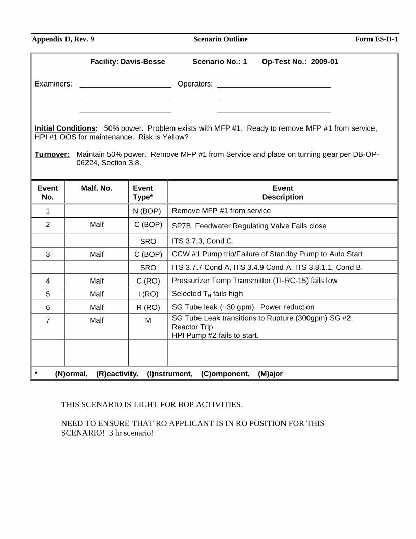
Appendix D, Rev. 9 Scenario Outline Form ES-D-1
Facility: Davis-Besse Scenario No.: 1 Op-Test No.: 2009-01 Examiners: Operators:
Initial Conditions: 50% power. Problem exists with MFP #1. Ready to remove MFP #1 from service, HPI #1 OOS for maintenance. Risk is Yellow?
Turnover: Maintain 50% power. Remove MFP #1 from Service and place on turning gear per DB-OP-
06224, Section 3.8.
Event No.
Malf. No. Event Type*
Event Description
1 N (BOP) Remove MFP #1 from service
2 Malf C (BOP) SP7B, Feedwater Regulating Valve Fails close
SRO ITS 3.7.3, Cond C.
3 Malf C (BOP) CCW #1 Pump trip/Failure of Standby Pump to Auto Start
SRO ITS 3.7.7 Cond A, ITS 3.4.9 Cond A, ITS 3.8.1.1, Cond B.
4 Malf C (RO) Pressurizer Temp Transmitter (TI-RC-15) fails low
5 Malf I (RO) Selected TH fails high
6 Malf R (RO) SG Tube leak (~30 gpm). Power reduction
7 Malf M SG Tube Leak transitions to Rupture (300gpm) SG #2. Reactor Trip HPI Pump #2 fails to start.
* (N)ormal, (R)eactivity, (I)nstrument, (C)omponent, (M)ajor THIS SCENARIO IS LIGHT FOR BOP ACTIVITIES. NEED TO ENSURE THAT RO APPLICANT IS IN RO POSITION FOR THIS SCENARIO! 3 hr scenario!
Appendix D, Rev. 9 Scenario #1 – General Description Form ES-D-1
Initial conditions for this scenario are that HPI Pump #1 is OOS for maintenance. A fault in included in the initial IC set that prevents HPI Pump #2 from starting. Operators will remove #1 MFP from service. SP7B, Feedwater Regulating Valve will fail closed. There are no panel manipulations for the BOP for this event. Hower, the SRO will need to review TS 3.7.3. The loss of CCW #2 pump will require BOP (or RO) operator to perform followup actions and require a Tech Spec review by the SRO. The operator actions must be completed before reaching RCP trip criteria. The selected pressurizer temperature instrument will fail low on slow ramp preventing SASS actuation. The SRO will direct actions from the abnormal procedures. The selected TH will fail high on a slow ramp to prevent SASS actuation. This will require immediate operator actions. The SRO may review of Technical Specifications but since the instrument that failed is a control instrument (input to ICS) and not an input to a safety system, Tech Specs will not apply. The #2 SG tube bundle will develop a leak (~30 gpm). This leak will get the SRO into the abnormal SG Leak procedure, DB-OP-02531 requiring a load reduction. After about 10 minutes, RP will report that SG #2 MS lines have higher radiation levels than SG #1. At this time, with approval from chief examiner, the simulator operator will ramp in a SGTR leak rate of about 300 gpm. With the RCS leak rate exceeding the capacity of one makeup pump, the SRO should order a reactor scram and enter into DB-OP-02000. The SRO will recognize that HPI pump #1 is OOS but HPI pump #2 will not start. Without both HPI pumps operating, RCS inventory control will rely on operation of both makeup pumps and isolation of letdown. In order to restore RCS inventory, the SRO will need to start the second makeup pump and isolate letdown. Starting the second makeup pump is considered a critical step since each makeup pump is rated for 150 gpm flow rate. With both makeup pumps running, flow will be just enough to keep up with the tube leak rate, so isolating letdown (closing MU2B and MU3) is also considered a critical task. Failing to start the second makeup pump and/or failing to isolate letdown will result in loss of RCS inventory that would complicate this accident sequence. During performance of DB-OP-02000, the SRO will need to ensure an adequate supply of water to the makeup pumps. Locking MU3971 and MU6405 in the BWST position will fulfill that requirement. The SRO will direct starting of LPI and piggyback LPI discharge into makeup pump suction increasing available flow rates from the makeup system. With the additional flow rates, the operators will be able to perform a cooldown with the SG tube leak and still be able to maintain positive control of RCS inventory. This would make locking open MU3971 and MU6405 and opening piggyback valves DH63 all critical steps and DH64. The scenario ends when the crew isolates SG#2 and commences a unit cooldown.
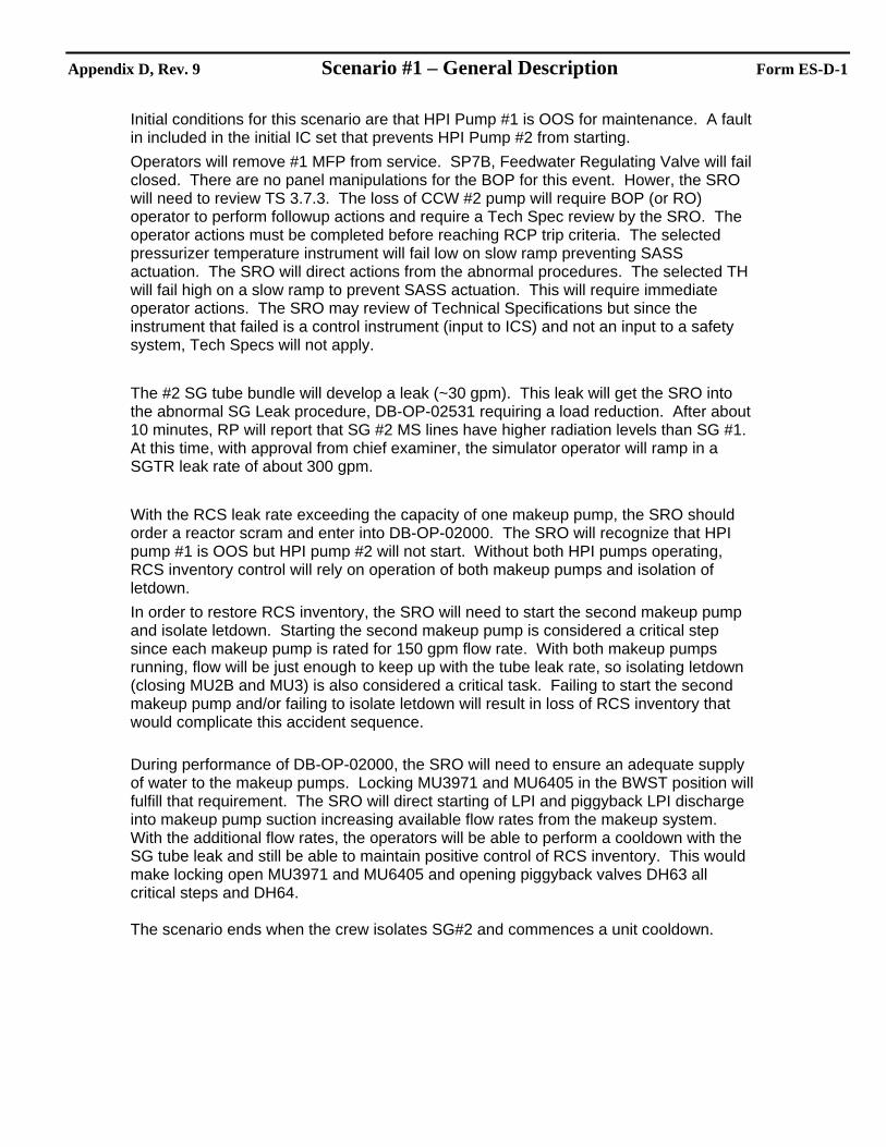
Appendix D, Rev. 9 Required Operator Actions Form ES-D-2
Op-Test No.: 2009-01 Scenario No.: 1 Page 3 of 20
Event Description: Scenario setup notes
Time Position Applicant’s Actions or Behavior
nrcsenario 1 ^ ^Set up 50% power ic 106 ^ ^Initial set up ^ ^ ^ HPI #1 out of service irf bfp1a rackout irf bfp1c true ^ ^ fails HPI 2 breaker open will not start imf bfp2c ^ ^ Fails CCW pump2 to auto start will strat by the switch imf ka34m ^ ^ Fails the aut push button offmain feed water loop ics 32b ior a11a1a12-7 off ^ ^ removes fuse for turbine bypass to keep them from going close imf l3m2b (10) normal ^ ^ select PZR 14-1 ^ ^ Trigger none ^ ^ ^ events ^ event 1 remove main feed pump from service crew ^
^ Event 2 ^ startup feed valve 7b closed imf fabbb (2) ^ ^ Event 3 ^ fails breaker for 1 ccw pump open imf ka30C (3) ^ ^ Event 4 ^ Fails PZR temp fails low mu32 opens imf h1c1c (4) 0.0 00:00:05 0.861 ^ ^ Event 5 ^ Fails selected TH fails high imf l1t6h (5) 1.0 00:00:20 0.74 ^ ^ Event 6 ^ otsg tube leak #2 otsg imf hh51 (6) 0.008 00:02:00 0.0
Post “Protected Train 2” signs.
Appendix D, Rev. 9 Required Operator Actions Form ES-D-2
Op-Test No.: 2009-01 Scenario No.: 1 Page 4 of 20
Event Description: Remove MFP #1 from Service
Time Position Applicant’s Actions or Behavior
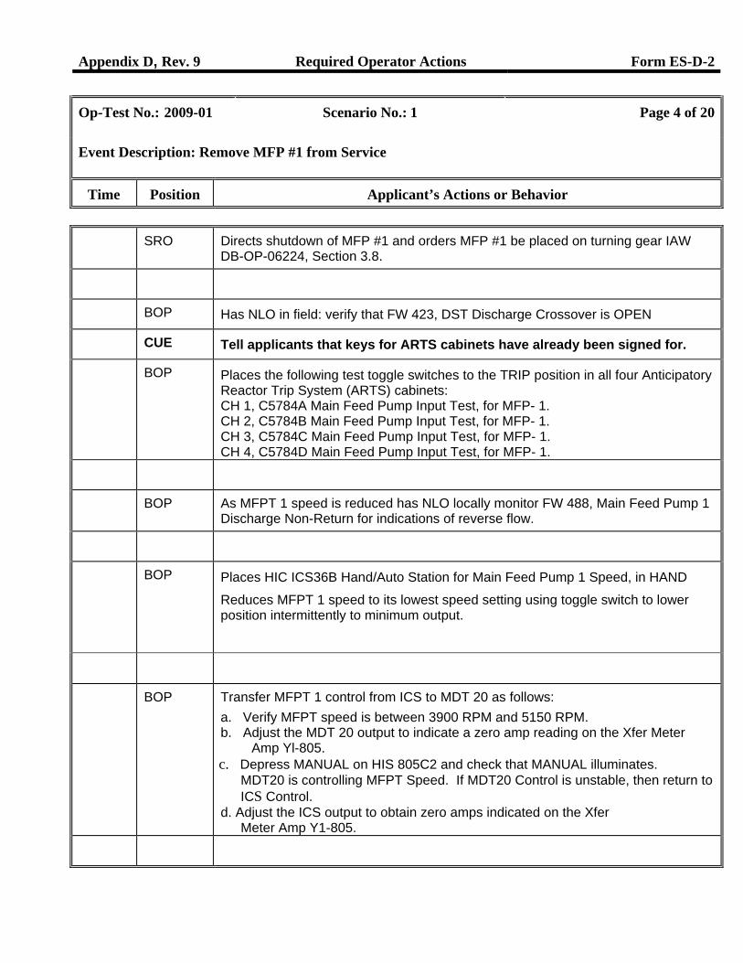
SRO Directs shutdown of MFP #1 and orders MFP #1 be placed on turning gear IAW DB-OP-06224, Section 3.8.
BOP Has NLO in field: verify that FW 423, DST Discharge Crossover is OPEN
CUE Tell applicants that keys for ARTS cabinets have already been signed for.
BOP Places the following test toggle switches to the TRIP position in all four Anticipatory Reactor Trip System (ARTS) cabinets: CH 1, C5784A Main Feed Pump Input Test, for MFP- 1. CH 2, C5784B Main Feed Pump Input Test, for MFP- 1. CH 3, C5784C Main Feed Pump Input Test, for MFP- 1. CH 4, C5784D Main Feed Pump Input Test, for MFP- 1.
BOP As MFPT 1 speed is reduced has NLO locally monitor FW 488, Main Feed Pump 1 Discharge Non-Return for indications of reverse flow.
BOP Places HIC ICS36B Hand/Auto Station for Main Feed Pump 1 Speed, in HAND
Reduces MFPT 1 speed to its lowest speed setting using toggle switch to lower position intermittently to minimum output.
BOP Transfer MFPT 1 control from ICS to MDT 20 as follows: a. Verify MFPT speed is between 3900 RPM and 5150 RPM. b. Adjust the MDT 20 output to indicate a zero amp reading on the Xfer Meter
Amp Yl-805. c. Depress MANUAL on HIS 805C2 and check that MANUAL illuminates.
MDT20 is controlling MFPT Speed. If MDT20 Control is unstable, then return to ICS Control.
d. Adjust the ICS output to obtain zero amps indicated on the Xfer Meter Amp Y1-805.
Appendix D, Rev. 9 Required Operator Actions Form ES-D-2
Op-Test No.: 2009-01 Scenario No.: 1 Page 5 of 20
Event Description: Remove MFP #1 from Service
Time Position Applicant’s Actions or Behavior
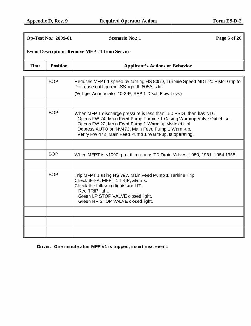
BOP Reduces MFPT 1 speed by turning HS 805D, Turbine Speed MDT 20 Pistol Grip to Decrease until green LSS light IL 805A is lit. (Will get Annunciator 10-2-E, BFP 1 Disch Flow Low.)
BOP When MFP 1 discharge pressure is less than 150 PSIG, then has NLO: Opens FW 24, Main Feed Pump Turbine 1 Casing Warmup Valve Outlet Isol. Opens FW 22, Main Feed Pump 1 Warm up vlv inlet isol. Depress AUTO on NV472, Main Feed Pump 1 Warm-up. Verify FW 472, Main Feed Pump 1 Warm-up, is operating.
BOP When MFPT is <1000 rpm, then opens TD Drain Valves: 1950, 1951, 1954 1955
BOP Trip MFPT 1 using HS 797, Main Feed Pump 1 Turbine Trip Check 8-4-A, MFPT 1 TRIP, alarms. Check the following lights are LIT: Red TRIP light. Green LP STOP VALVE closed light. Green HP STOP VALVE closed light.
Driver: One minute after MFP #1 is tripped, insert next event.
Appendix D, Rev. 9 Required Operator Actions Form ES-D-2
Op-Test No.: 2009-01 Scenario No.: 1 Page 6 of 20
Event Description: SP7B, Feedwater Regulating Valve Fails close
Time Position Applicant’s Actions or Behavior
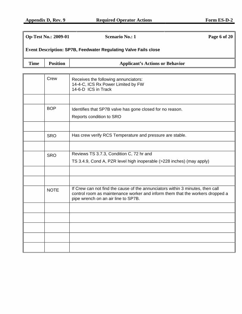
Crew Receives the following annunciators: 14-4-C, ICS Rx Power Limited by FW 14-6-D ICS in Track
BOP Identifies that SP7B valve has gone closed for no reason.
Reports condition to SRO
SRO Has crew verify RCS Temperature and pressure are stable.
SRO Reviews TS 3.7.3, Condition C, 72 hr and
TS 3.4.9, Cond A, PZR level high inoperable (>228 inches) (may apply)
NOTE If Crew can not find the cause of the annunciators within 3 minutes, then call control room as maintenance worker and inform them that the workers dropped a pipe wrench on an air line to SP7B.
Appendix D, Rev. 9 Required Operator Actions Form ES-D-2
Op-Test No.: 2009-01 Scenario No.: 1 Page 7 of 20
Event Description: CCW #1 Pump trip/Failure of Standby Pump to Auto Start
Time Position Applicant’s Actions or Behavior
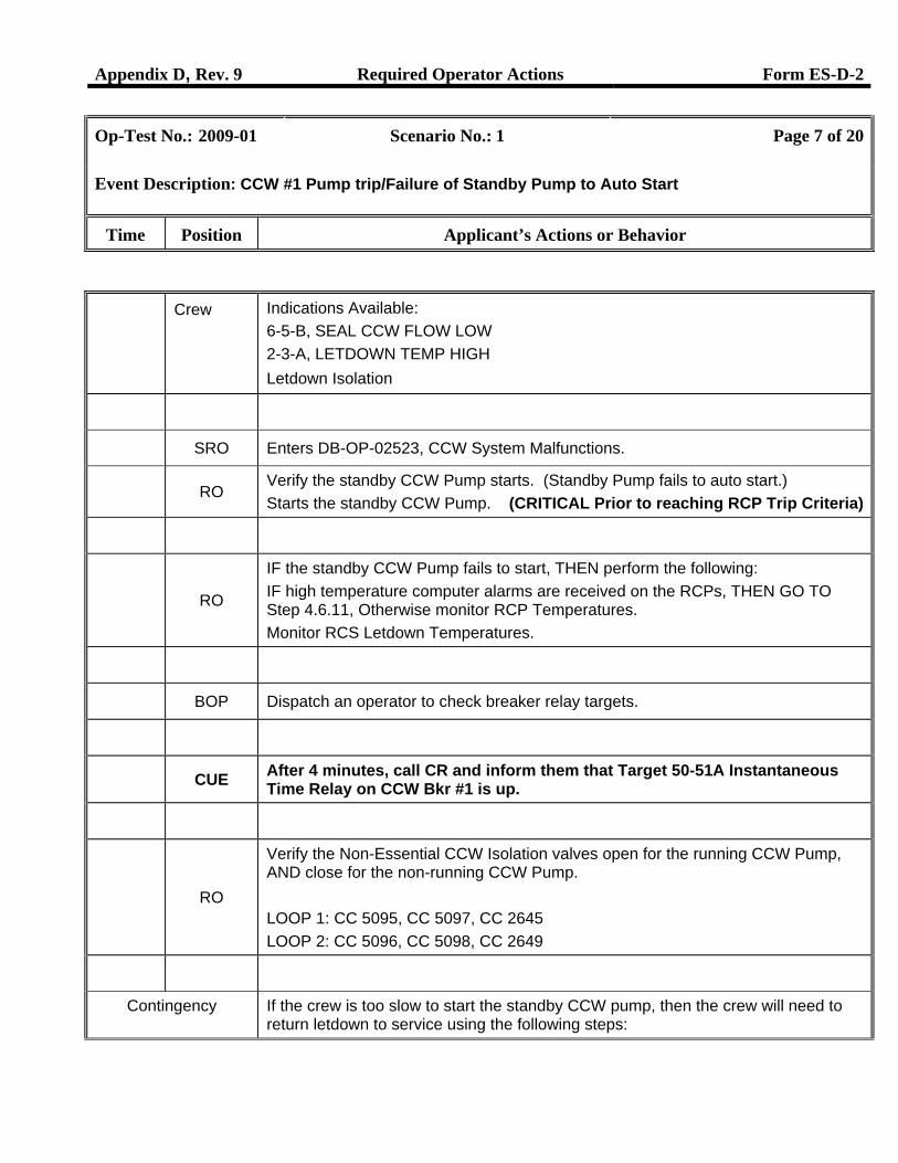
Crew Indications Available: 6-5-B, SEAL CCW FLOW LOW 2-3-A, LETDOWN TEMP HIGH Letdown Isolation
SRO Enters DB-OP-02523, CCW System Malfunctions.
RO Verify the standby CCW Pump starts. (Standby Pump fails to auto start.) Starts the standby CCW Pump. (CRITICAL Prior to reaching RCP Trip Criteria)
RO
IF the standby CCW Pump fails to start, THEN perform the following: IF high temperature computer alarms are received on the RCPs, THEN GO TO Step 4.6.11, Otherwise monitor RCP Temperatures. Monitor RCS Letdown Temperatures.
BOP Dispatch an operator to check breaker relay targets.
CUE After 4 minutes, call CR and inform them that Target 50-51A Instantaneous Time Relay on CCW Bkr #1 is up.
RO
Verify the Non-Essential CCW Isolation valves open for the running CCW Pump, AND close for the non-running CCW Pump. LOOP 1: CC 5095, CC 5097, CC 2645 LOOP 2: CC 5096, CC 5098, CC 2649
Contingency If the crew is too slow to start the standby CCW pump, then the crew will need to return letdown to service using the following steps:
Appendix D, Rev. 9 Required Operator Actions Form ES-D-2
Op-Test No.: 2009-01 Scenario No.: 1 Page 8 of 20
Event Description: CCW #1 Pump trip/Failure of Standby Pump to Auto Start
Time Position Applicant’s Actions or Behavior
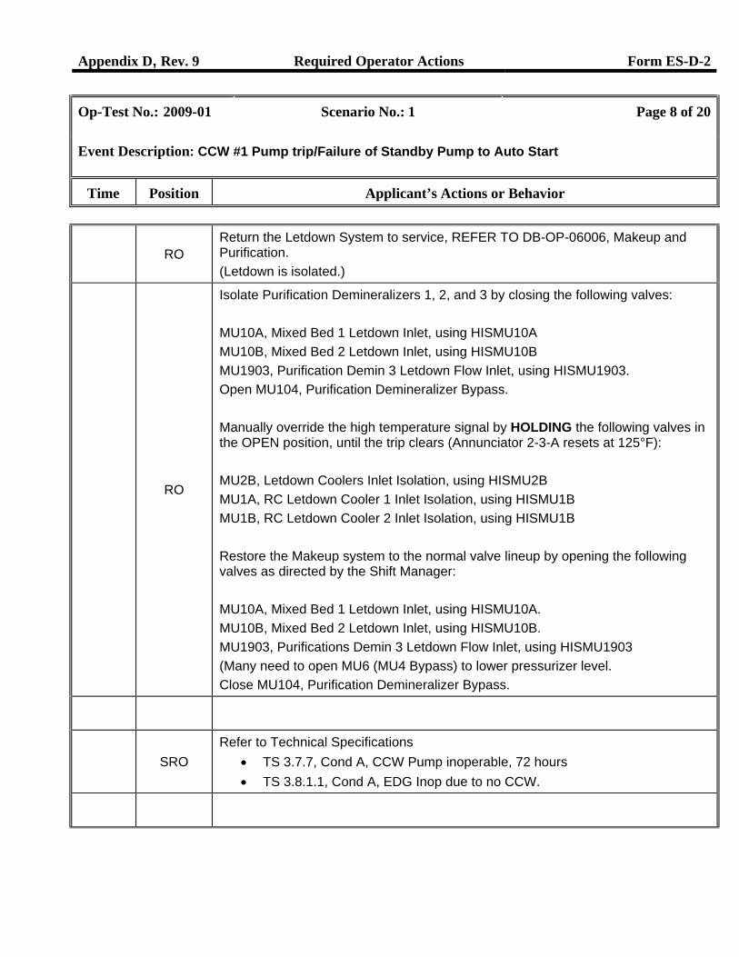
RO
Return the Letdown System to service, REFER TO DB-OP-06006, Makeup and Purification. (Letdown is isolated.)
RO
Isolate Purification Demineralizers 1, 2, and 3 by closing the following valves: MU10A, Mixed Bed 1 Letdown Inlet, using HISMU10A MU10B, Mixed Bed 2 Letdown Inlet, using HISMU10B MU1903, Purification Demin 3 Letdown Flow Inlet, using HISMU1903. Open MU104, Purification Demineralizer Bypass. Manually override the high temperature signal by HOLDING the following valves in the OPEN position, until the trip clears (Annunciator 2-3-A resets at 125°F): MU2B, Letdown Coolers Inlet Isolation, using HISMU2B MU1A, RC Letdown Cooler 1 Inlet Isolation, using HISMU1B MU1B, RC Letdown Cooler 2 Inlet Isolation, using HISMU1B Restore the Makeup system to the normal valve lineup by opening the following valves as directed by the Shift Manager: MU10A, Mixed Bed 1 Letdown Inlet, using HISMU10A. MU10B, Mixed Bed 2 Letdown Inlet, using HISMU10B. MU1903, Purifications Demin 3 Letdown Flow Inlet, using HISMU1903 (Many need to open MU6 (MU4 Bypass) to lower pressurizer level. Close MU104, Purification Demineralizer Bypass.
SRO Refer to Technical Specifications
• TS 3.7.7, Cond A, CCW Pump inoperable, 72 hours • TS 3.8.1.1, Cond A, EDG Inop due to no CCW.
Appendix D, Rev. 9 Required Operator Actions Form ES-D-2
Op-Test No.: 2009-01 Scenario No.: 1 Page 9 of 20
Event Description: Pressurizer Temp Transmitter (TI-RC-15) fails low, MU32 fails to Open.
Time Position Applicant’s Actions or Behavior
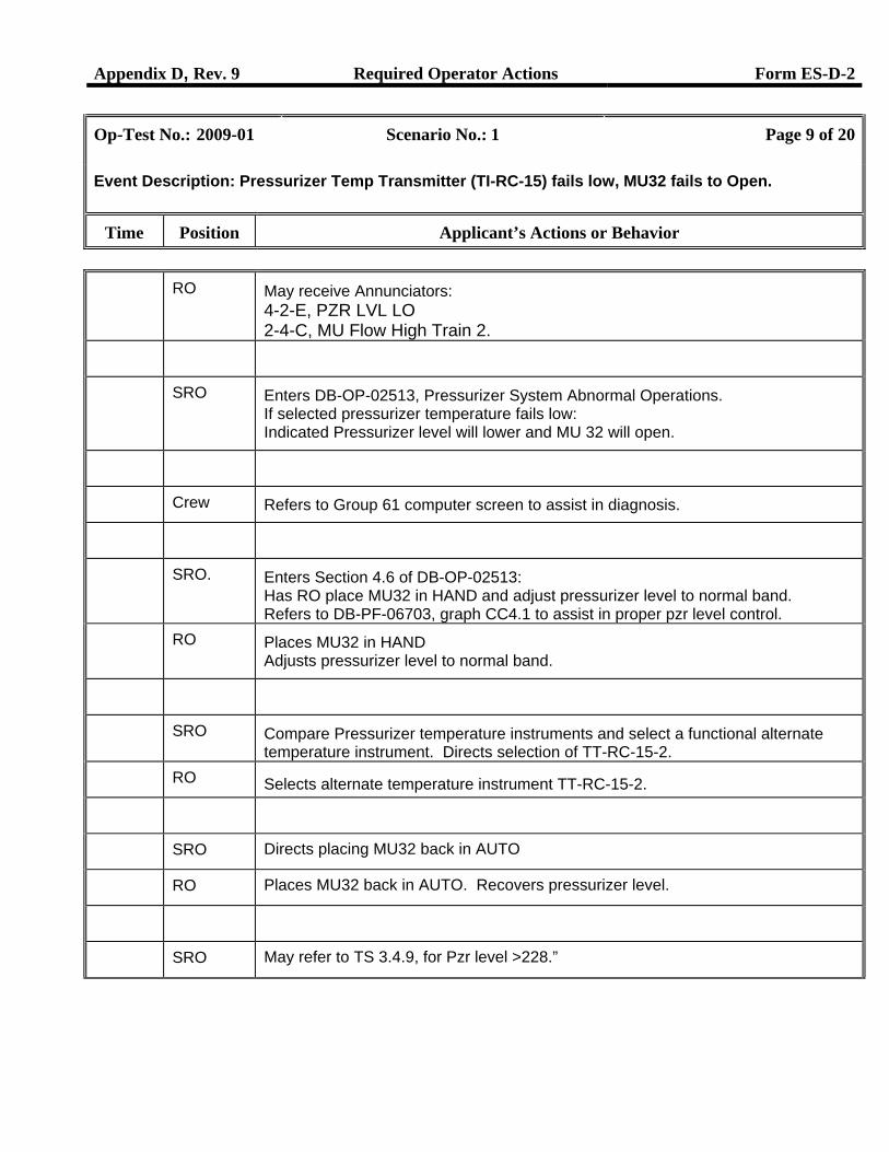
RO May receive Annunciators: 4-2-E, PZR LVL LO 2-4-C, MU Flow High Train 2.
SRO Enters DB-OP-02513, Pressurizer System Abnormal Operations. If selected pressurizer temperature fails low: Indicated Pressurizer level will lower and MU 32 will open.
Crew Refers to Group 61 computer screen to assist in diagnosis.
SRO. Enters Section 4.6 of DB-OP-02513: Has RO place MU32 in HAND and adjust pressurizer level to normal band. Refers to DB-PF-06703, graph CC4.1 to assist in proper pzr level control.
RO Places MU32 in HAND Adjusts pressurizer level to normal band.
SRO Compare Pressurizer temperature instruments and select a functional alternate temperature instrument. Directs selection of TT-RC-15-2.
RO Selects alternate temperature instrument TT-RC-15-2.
SRO Directs placing MU32 back in AUTO
RO Places MU32 back in AUTO. Recovers pressurizer level.
SRO May refer to TS 3.4.9, for Pzr level >228.”
Appendix D, Rev. 9 Required Operator Actions Form ES-D-2
Op-Test No.: 2009-01 Scenario No.: 1 Page 10 of 20
Event Description: TH (TT-RC3A1) Fails High
Time Position Applicant’s Actions or Behavior
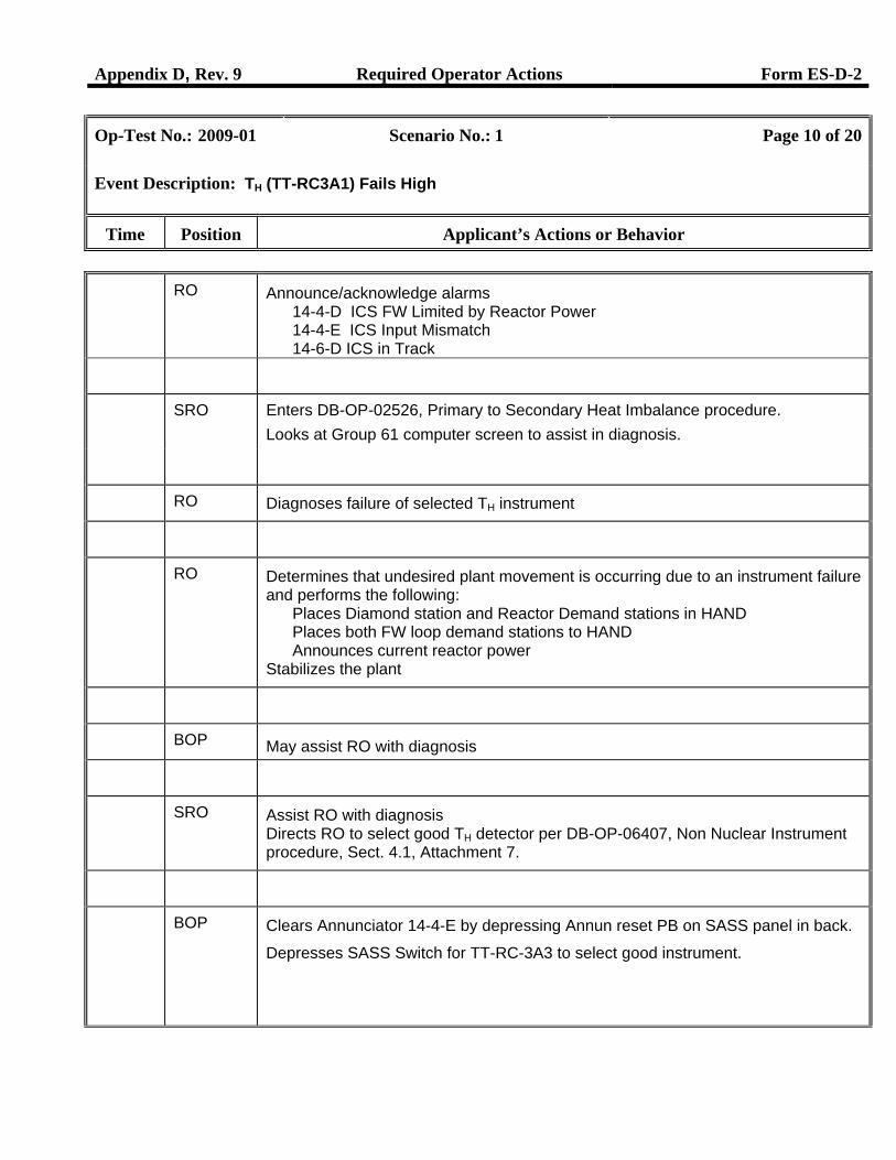
RO Announce/acknowledge alarms 14-4-D ICS FW Limited by Reactor Power 14-4-E ICS Input Mismatch 14-6-D ICS in Track
SRO Enters DB-OP-02526, Primary to Secondary Heat Imbalance procedure.
Looks at Group 61 computer screen to assist in diagnosis.
RO Diagnoses failure of selected TH instrument
RO Determines that undesired plant movement is occurring due to an instrument failure and performs the following:
Places Diamond station and Reactor Demand stations in HAND Places both FW loop demand stations to HAND Announces current reactor power
Stabilizes the plant
BOP May assist RO with diagnosis
SRO Assist RO with diagnosis Directs RO to select good TH detector per DB-OP-06407, Non Nuclear Instrument procedure, Sect. 4.1, Attachment 7.
BOP Clears Annunciator 14-4-E by depressing Annun reset PB on SASS panel in back.
Depresses SASS Switch for TT-RC-3A3 to select good instrument.
Appendix D, Rev. 9 Required Operator Actions Form ES-D-2
Op-Test No.: 2009-01 Scenario No.: 1 Page 11 of 20
Event Description: TH (TT-RC3A1) Fails High
Time Position Applicant’s Actions or Behavior
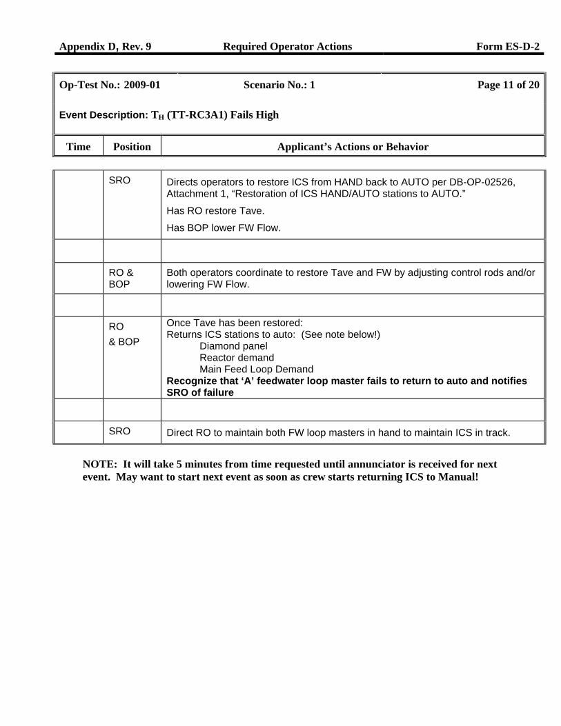
SRO Directs operators to restore ICS from HAND back to AUTO per DB-OP-02526, Attachment 1, “Restoration of ICS HAND/AUTO stations to AUTO.”
Has RO restore Tave.
Has BOP lower FW Flow.
RO & BOP
Both operators coordinate to restore Tave and FW by adjusting control rods and/or lowering FW Flow.
RO & BOP
Once Tave has been restored: Returns ICS stations to auto: (See note below!)
Diamond panel Reactor demand Main Feed Loop Demand
Recognize that ‘A’ feedwater loop master fails to return to auto and notifies SRO of failure
SRO Direct RO to maintain both FW loop masters in hand to maintain ICS in track.
NOTE: It will take 5 minutes from time requested until annunciator is received for next event. May want to start next event as soon as crew starts returning ICS to Manual!
Appendix D, Rev. 9 Required Operator Actions Form ES-D-2
Op-Test No.: 2009-01 Scenario No.: 1 Page 12 of 20
Event Description: SG #2 Tube Leak / Power Reduction
Time Position Applicant’s Actions or Behavior
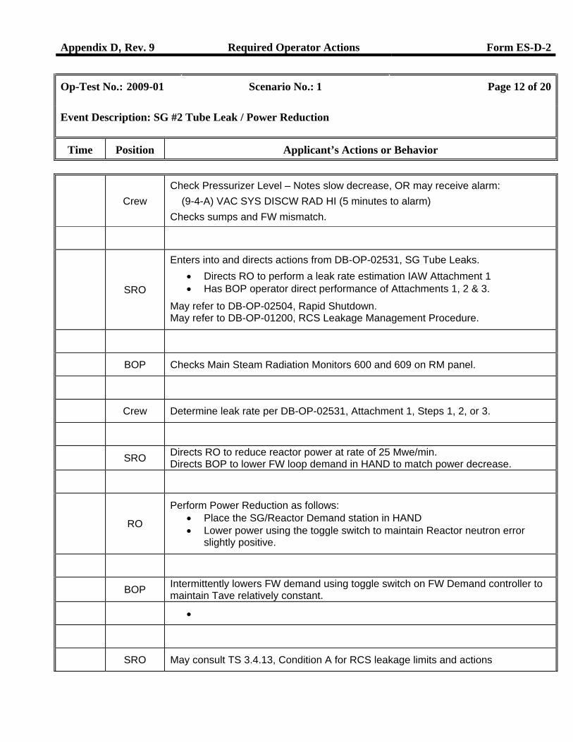
Crew
Check Pressurizer Level – Notes slow decrease, OR may receive alarm: (9-4-A) VAC SYS DISCW RAD HI (5 minutes to alarm) Checks sumps and FW mismatch.
SRO
Enters into and directs actions from DB-OP-02531, SG Tube Leaks. • Directs RO to perform a leak rate estimation IAW Attachment 1 • Has BOP operator direct performance of Attachments 1, 2 & 3.
May refer to DB-OP-02504, Rapid Shutdown. May refer to DB-OP-01200, RCS Leakage Management Procedure.
BOP Checks Main Steam Radiation Monitors 600 and 609 on RM panel.
Crew Determine leak rate per DB-OP-02531, Attachment 1, Steps 1, 2, or 3.
SRO Directs RO to reduce reactor power at rate of 25 Mwe/min. Directs BOP to lower FW loop demand in HAND to match power decrease.
RO
Perform Power Reduction as follows: • Place the SG/Reactor Demand station in HAND • Lower power using the toggle switch to maintain Reactor neutron error
slightly positive.
BOP Intermittently lowers FW demand using toggle switch on FW Demand controller to maintain Tave relatively constant.
•
SRO May consult TS 3.4.13, Condition A for RCS leakage limits and actions
Appendix D, Rev. 9 Required Operator Actions Form ES-D-2
Op-Test No.: 2009-01 Scenario No.: 1 Page 13 of 20
Event Description: SG #2 Tube Leak / Power Reduction
Time Position Applicant’s Actions or Behavior
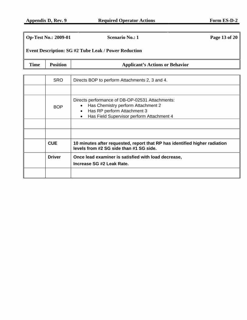
SRO Directs BOP to perform Attachments 2, 3 and 4.
BOP
Directs performance of DB-OP-02531 Attachments: • Has Chemistry perform Attachment 2 • Has RP perform Attachment 3 • Has Field Supervisor perform Attachment 4
CUE 10 minutes after requested, report that RP has identified higher radiation levels from #2 SG side than #1 SG side.
Driver Once lead examiner is satisfied with load decrease, Increase SG #2 Leak Rate.
Appendix D, Rev. 9 Required Operator Actions Form ES-D-2
Op-Test No.: 2009-01 Scenario No.: 1 Page 14 of 20
Event Description: SG #2 Tube Rupture / Reactor Trip / Failure of HPI Pump #2
Time Position Applicant’s Actions or Behavior
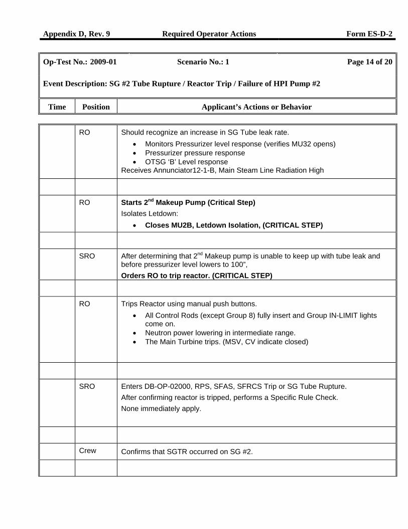
RO Should recognize an increase in SG Tube leak rate. • Monitors Pressurizer level response (verifies MU32 opens) • Pressurizer pressure response • OTSG ‘B’ Level response
Receives Annunciator12-1-B, Main Steam Line Radiation High
RO Starts 2nd Makeup Pump (Critical Step) Isolates Letdown:
• Closes MU2B, Letdown Isolation, (CRITICAL STEP)
SRO After determining that 2nd Makeup pump is unable to keep up with tube leak and before pressurizer level lowers to 100”, Orders RO to trip reactor. (CRITICAL STEP)
RO Trips Reactor using manual push buttons. • All Control Rods (except Group 8) fully insert and Group IN-LIMIT lights
come on. • Neutron power lowering in intermediate range. • The Main Turbine trips. (MSV, CV indicate closed)
SRO Enters DB-OP-02000, RPS, SFAS, SFRCS Trip or SG Tube Rupture. After confirming reactor is tripped, performs a Specific Rule Check. None immediately apply.
Crew Confirms that SGTR occurred on SG #2.
Appendix D, Rev. 9 Required Operator Actions Form ES-D-2
Op-Test No.: 2009-01 Scenario No.: 1 Page 15 of 20
Event Description: SG #2 Tube Rupture / Reactor Trip / Failure of HPI Pump #2
Time Position Applicant’s Actions or Behavior
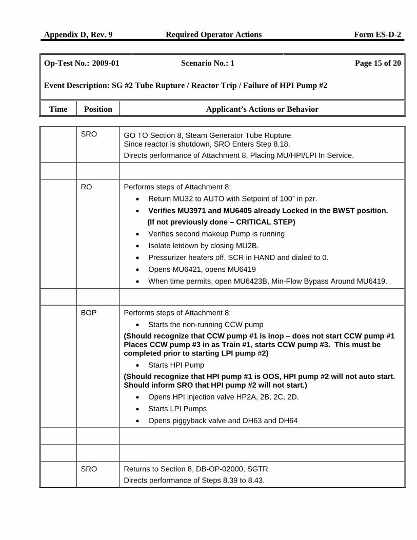
SRO GO TO Section 8, Steam Generator Tube Rupture. Since reactor is shutdown, SRO Enters Step 8.18, Directs performance of Attachment 8, Placing MU/HPI/LPI In Service.
RO Performs steps of Attachment 8: • Return MU32 to AUTO with Setpoint of 100” in pzr. • Verifies MU3971 and MU6405 already Locked in the BWST position.
(If not previously done – CRITICAL STEP) • Verifies second makeup Pump is running • Isolate letdown by closing MU2B. • Pressurizer heaters off, SCR in HAND and dialed to 0. • Opens MU6421, opens MU6419 • When time permits, open MU6423B, Min-Flow Bypass Around MU6419.
BOP Performs steps of Attachment 8: • Starts the non-running CCW pump
(Should recognize that CCW pump #1 is inop – does not start CCW pump #1 Places CCW pump #3 in as Train #1, starts CCW pump #3. This must be completed prior to starting LPI pump #2)
• Starts HPI Pump (Should recognize that HPI pump #1 is OOS, HPI pump #2 will not auto start. Should inform SRO that HPI pump #2 will not start.)
• Opens HPI injection valve HP2A, 2B, 2C, 2D. • Starts LPI Pumps • Opens piggyback valve and DH63 and DH64
SRO Returns to Section 8, DB-OP-02000, SGTR Directs performance of Steps 8.39 to 8.43.
Appendix D, Rev. 9 Required Operator Actions Form ES-D-2
Op-Test No.: 2009-01 Scenario No.: 1 Page 16 of 20
Event Description: SG #2 Tube Rupture / Reactor Trip / Failure of HPI Pump #2
Time Position Applicant’s Actions or Behavior
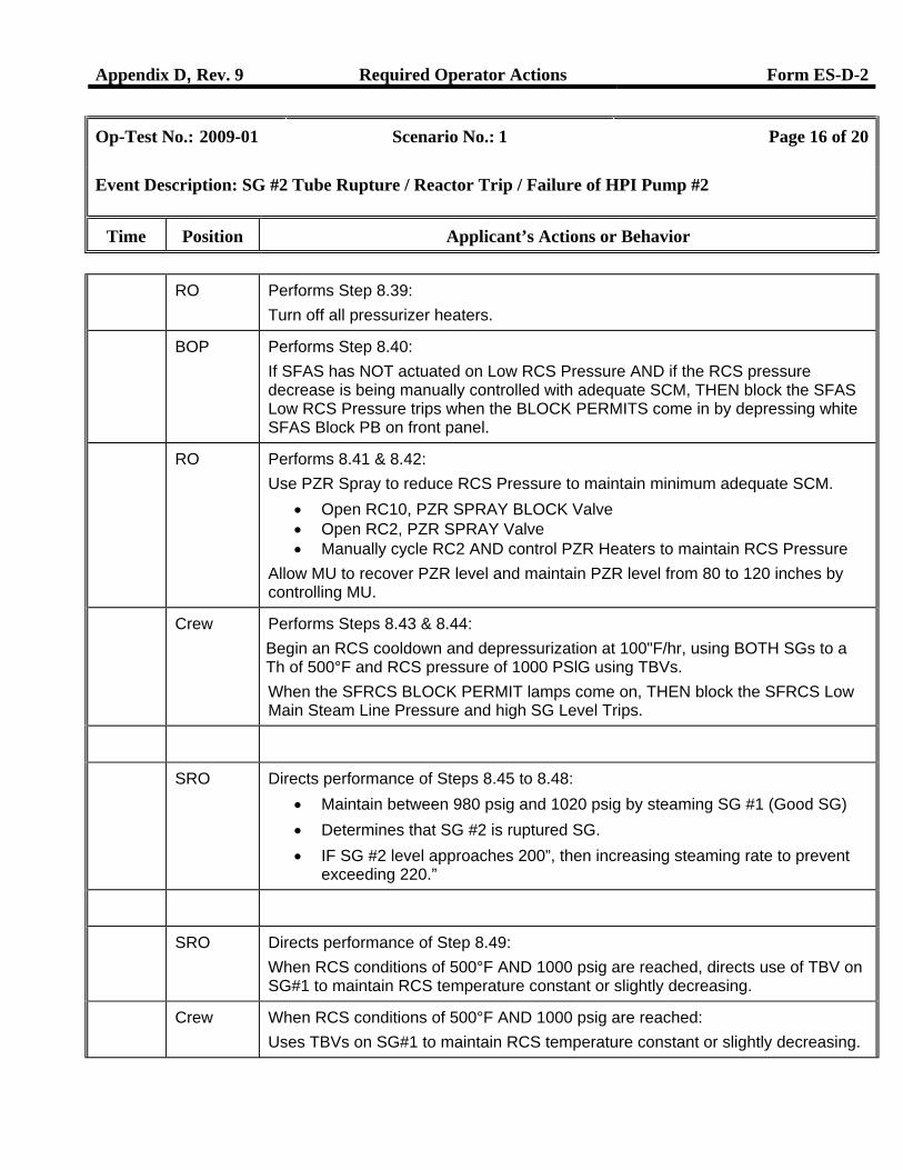
RO Performs Step 8.39: Turn off all pressurizer heaters.
BOP Performs Step 8.40: If SFAS has NOT actuated on Low RCS Pressure AND if the RCS pressure decrease is being manually controlled with adequate SCM, THEN block the SFAS Low RCS Pressure trips when the BLOCK PERMITS come in by depressing white SFAS Block PB on front panel.
RO Performs 8.41 & 8.42: Use PZR Spray to reduce RCS Pressure to maintain minimum adequate SCM.
• Open RC10, PZR SPRAY BLOCK Valve • Open RC2, PZR SPRAY Valve • Manually cycle RC2 AND control PZR Heaters to maintain RCS Pressure
Allow MU to recover PZR level and maintain PZR level from 80 to 120 inches by controlling MU.
Crew Performs Steps 8.43 & 8.44: Begin an RCS cooldown and depressurization at 100"F/hr, using BOTH SGs to a Th of 500°F and RCS pressure of 1000 PSlG using TBVs. When the SFRCS BLOCK PERMIT lamps come on, THEN block the SFRCS Low Main Steam Line Pressure and high SG Level Trips.
SRO Directs performance of Steps 8.45 to 8.48: • Maintain between 980 psig and 1020 psig by steaming SG #1 (Good SG) • Determines that SG #2 is ruptured SG. • IF SG #2 level approaches 200”, then increasing steaming rate to prevent
exceeding 220.”
SRO Directs performance of Step 8.49: When RCS conditions of 500°F AND 1000 psig are reached, directs use of TBV on SG#1 to maintain RCS temperature constant or slightly decreasing.
Crew When RCS conditions of 500°F AND 1000 psig are reached: Uses TBVs on SG#1 to maintain RCS temperature constant or slightly decreasing.
Appendix D, Rev. 9 Required Operator Actions Form ES-D-2
Op-Test No.: 2009-01 Scenario No.: 1 Page 17 of 20
Event Description: SG #2 Tube Rupture / Reactor Trip / Failure of HPI Pump #2
Time Position Applicant’s Actions or Behavior
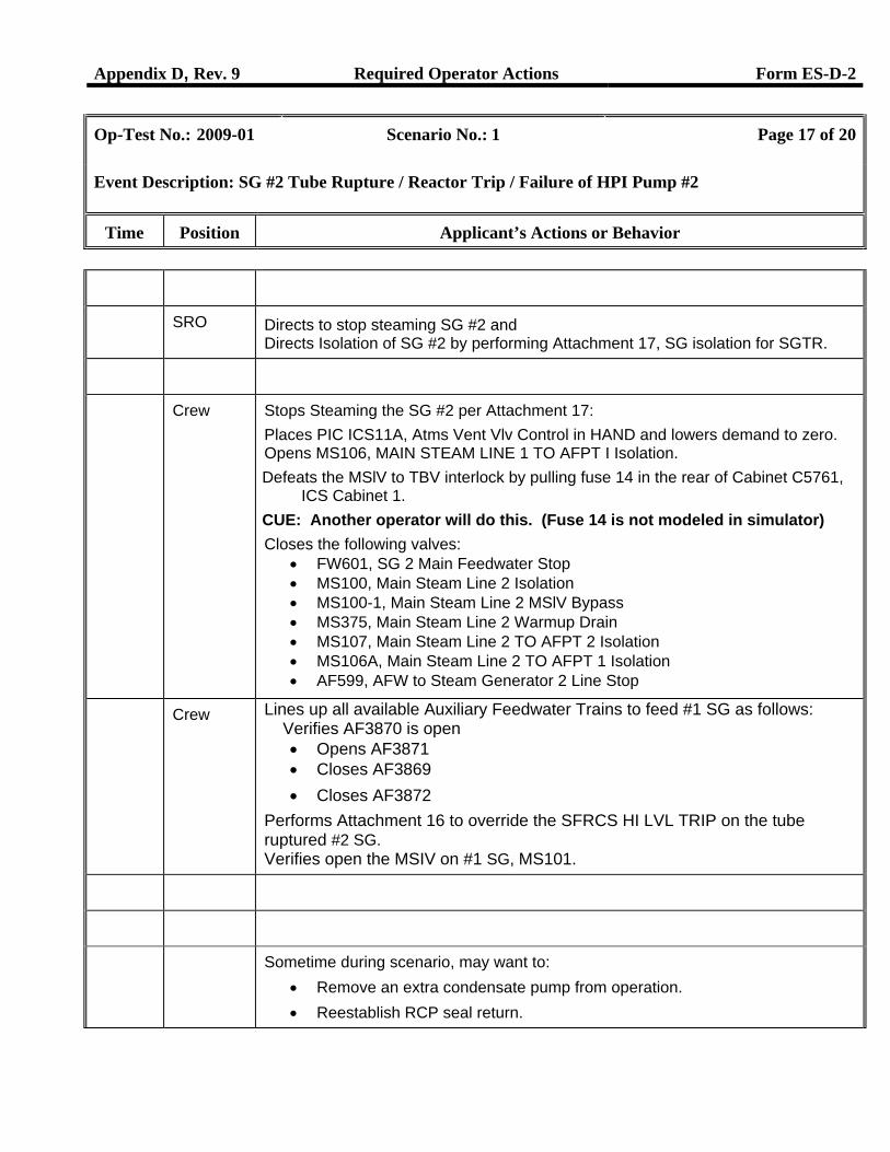
SRO Directs to stop steaming SG #2 and Directs Isolation of SG #2 by performing Attachment 17, SG isolation for SGTR.
Crew Stops Steaming the SG #2 per Attachment 17: Places PIC ICS11A, Atms Vent Vlv Control in HAND and lowers demand to zero. Opens MS106, MAIN STEAM LINE 1 TO AFPT I Isolation. Defeats the MSlV to TBV interlock by pulling fuse 14 in the rear of Cabinet C5761,
ICS Cabinet 1. CUE: Another operator will do this. (Fuse 14 is not modeled in simulator) Closes the following valves:
• FW601, SG 2 Main Feedwater Stop • MS100, Main Steam Line 2 Isolation • MS100-1, Main Steam Line 2 MSlV Bypass • MS375, Main Steam Line 2 Warmup Drain • MS107, Main Steam Line 2 TO AFPT 2 Isolation • MS106A, Main Steam Line 2 TO AFPT 1 Isolation • AF599, AFW to Steam Generator 2 Line Stop
Crew Lines up all available Auxiliary Feedwater Trains to feed #1 SG as follows: Verifies AF3870 is open
• Opens AF3871 • Closes AF3869 • Closes AF3872
Performs Attachment 16 to override the SFRCS HI LVL TRIP on the tube ruptured #2 SG. Verifies open the MSIV on #1 SG, MS101.
Sometime during scenario, may want to: • Remove an extra condensate pump from operation. • Reestablish RCP seal return.
Appendix D, Rev. 9 Required Operator Actions Form ES-D-2
Op-Test No.: 2009-01 Scenario No.: 1 Page 18 of 20
Event Description: SG #2 Tube Rupture / Reactor Trip / Failure of HPI Pump #2
Time Position Applicant’s Actions or Behavior
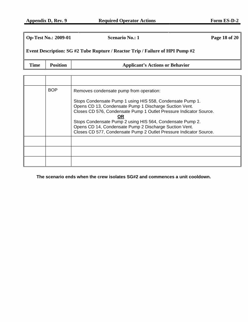
BOP Removes condensate pump from operation: Stops Condensate Pump 1 using HIS 558, Condensate Pump 1. Opens CD 13, Condensate Pump 1 Discharge Suction Vent. Closes CD 576, Condensate Pump 1 Outlet Pressure Indicator Source.
OR Stops Condensate Pump 2 using HIS 564, Condensate Pump 2. Opens CD 14, Condensate Pump 2 Discharge Suction Vent. Closes CD 577, Condensate Pump 2 Outlet Pressure Indicator Source.
The scenario ends when the crew isolates SG#2 and commences a unit cooldown.
Appendix D, Rev. 9 Scenario Critical Tasks Form ES-D-1
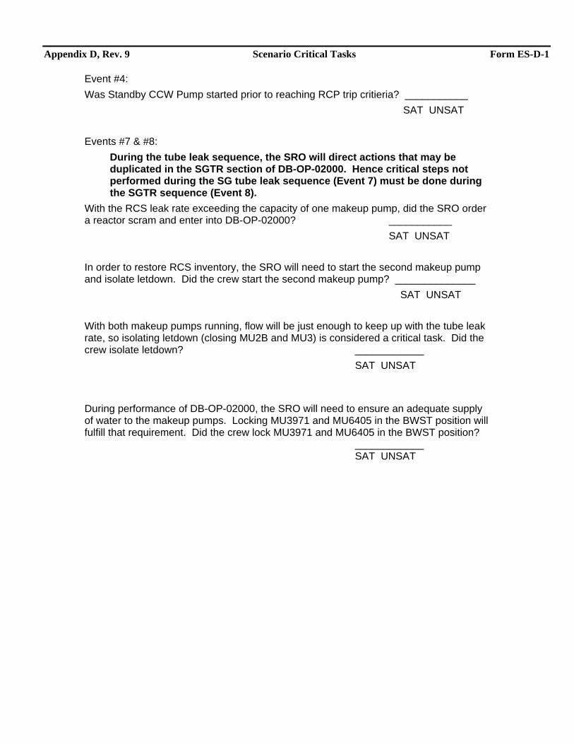
Event #4: Was Standby CCW Pump started prior to reaching RCP trip critieria? ___________ SAT UNSAT Events #7 & #8:
During the tube leak sequence, the SRO will direct actions that may be duplicated in the SGTR section of DB-OP-02000. Hence critical steps not performed during the SG tube leak sequence (Event 7) must be done during the SGTR sequence (Event 8).
With the RCS leak rate exceeding the capacity of one makeup pump, did the SRO order a reactor scram and enter into DB-OP-02000? ___________ SAT UNSAT In order to restore RCS inventory, the SRO will need to start the second makeup pump and isolate letdown. Did the crew start the second makeup pump? ______________ SAT UNSAT With both makeup pumps running, flow will be just enough to keep up with the tube leak rate, so isolating letdown (closing MU2B and MU3) is considered a critical task. Did the crew isolate letdown? ____________ SAT UNSAT During performance of DB-OP-02000, the SRO will need to ensure an adequate supply of water to the makeup pumps. Locking MU3971 and MU6405 in the BWST position will fulfill that requirement. Did the crew lock MU3971 and MU6405 in the BWST position? ____________ SAT UNSAT
Appendix D, Rev. 9 Form ES-D-1
TURNOVER Initial Conditions: 50% power. Problem exists with MFP #1. Ready to remove MFP #1 from service, HPI #1 OOS for seal repair, 24 hours into 72 hour LCO.
Turnover: Lower Reactor power then remove MFP #1 from service for seal replacement on the booster pump IAW DB-OP-06224, Section 3.8.
Appendix D, Rev. 9 Scenario Outline Form ES-D-1
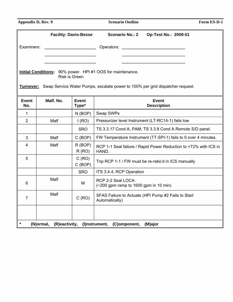
Facility: Davis-Besse Scenario No.: 2 Op-Test No.: 2009-01 Examiners: Operators:
Initial Conditions: 90% power. HPI #1 OOS for maintenance.
Risk is Green
Turnover: Swap Service Water Pumps, escalate power to 100% per grid dispatcher request.
Event No.
Malf. No. Event Type*
Event Description
1 N (BOP) Swap SWPs
2 Malf I (RO) Pressurizer level Instrument (LT-RC14-1) fails low
SRO TS 3.3.17 Cond A, PAM; TS 3.3.8 Cond A Remote S/D panel.
3 Malf C (BOP) FW Temperature Instrument (TT-SPI-1) fails to 0 over 4 minutes.
4 Malf R (BOP) R (RO)
RCP 1-1 Seal failure / Rapid Power Reduction to <72% with ICS in HAND.
5 C (RO) C (BOP)
Trip RCP 1-1 / FW must be re-ratio’d in ICS manually
SRO ITS 3.4.4, RCP Operation
6 Malf
M RCP 2-2 Seal LOCA (~200 gpm ramp to 1600 gpm in 10 min)
7 Malf
C (RO) SFAS Failure to Actuate (HPI Pump #2 Fails to Start Automatically)
* (N)ormal, (R)eactivity, (I)nstrument, (C)omponent, (M)ajor
Appendix D, Rev. 9 Scenario #2 General Description Form ES-D-1
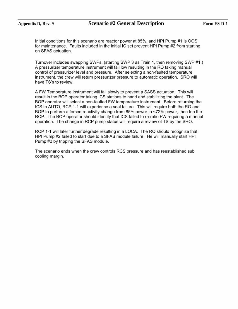
Initial conditions for this scenario are reactor power at 85%, and HPI Pump #1 is OOS for maintenance. Faults included in the initial IC set prevent HPI Pump #2 from starting on SFAS actuation. Turnover includes swapping SWPs, (starting SWP 3 as Train 1, then removing SWP #1.) A pressurizer temperature instrument will fail low resulting in the RO taking manual control of pressurizer level and pressure. After selecting a non-faulted temperature instrument, the crew will return pressurizer pressure to automatic operation. SRO will have TS’s to review. A FW Temperature instrument will fail slowly to prevent a SASS actuation. This will result in the BOP operator taking ICS stations to hand and stabilizing the plant. The BOP operator will select a non-faulted FW temperature instrument. Before returning the ICS to AUTO, RCP 1-1 will experience a seal failure. This will require both the RO and BOP to perform a forced reactivity change from 85% power to <72% power, then trip the RCP. The BOP operator should identify that ICS failed to re-ratio FW requiring a manual operation. The change in RCP pump status will require a review of TS by the SRO. RCP 1-1 will later further degrade resulting in a LOCA. The RO should recognize that HPI Pump #2 failed to start due to a SFAS module failure. He will manually start HPI Pump #2 by tripping the SFAS module. The scenario ends when the crew controls RCS pressure and has reestablished sub cooling margin.
Appendix D, Rev. 9 Required Operator Actions Form ES-D-2
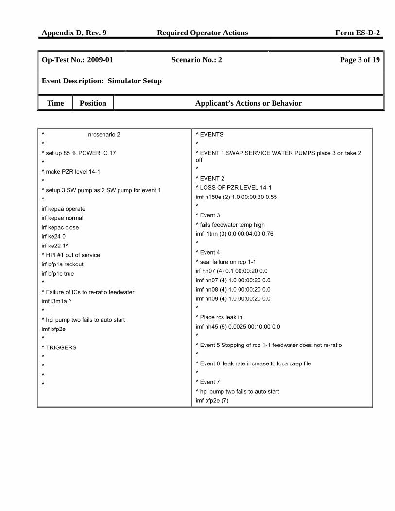
Op-Test No.: 2009-01 Scenario No.: 2 Page 3 of 19
Event Description: Simulator Setup
Time Position Applicant’s Actions or Behavior
^ nrcsenario 2 ^ ^ set up 85 % POWER IC 17 ^ ^ make PZR level 14-1 ^ ^ setup 3 SW pump as 2 SW pump for event 1 ^ irf kepaa operate irf kepae normal irf kepac close irf ke24 0 irf ke22 1^ ^ HPI #1 out of service irf bfp1a rackout irf bfp1c true ^ ^ Failure of ICs to re-ratio feedwater imf l3m1a ^ ^ ^ hpi pump two fails to auto start imf bfp2e ^ ^ TRIGGERS ^ ^ ^ ^
^ EVENTS ^ ^ EVENT 1 SWAP SERVICE WATER PUMPS place 3 on take 2 off ^ ^ EVENT 2 ^ LOSS OF PZR LEVEL 14-1 imf h150e (2) 1.0 00:00:30 0.55 ^ ^ Event 3 ^ fails feedwater temp high imf l1tnn (3) 0.0 00:04:00 0.76 ^ ^ Event 4 ^ seal failure on rcp 1-1 irf hn07 (4) 0.1 00:00:20 0.0 imf hn07 (4) 1.0 00:00:20 0.0 imf hn08 (4) 1.0 00:00:20 0.0 imf hn09 (4) 1.0 00:00:20 0.0 ^ ^ Place rcs leak in imf hh45 (5) 0.0025 00:10:00 0.0 ^ ^ Event 5 Stopping of rcp 1-1 feedwater does not re-ratio ^ ^ Event 6 leak rate increase to loca caep file ^ ^ Event 7 ^ hpi pump two fails to auto start imf bfp2e (7)
Appendix D, Rev. 9 Required Operator Actions Form ES-D-2
Op-Test No.: 2009-01 Scenario No.: 2 Page 4 of 19
Event Description: Swap Service Water Pumps
Time Position Applicant’s Actions or Behavior
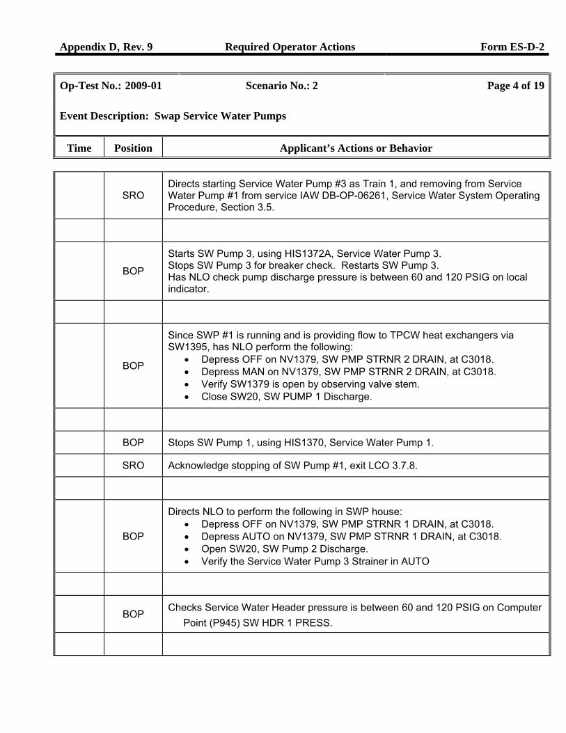
SRO
Directs starting Service Water Pump #3 as Train 1, and removing from Service Water Pump #1 from service IAW DB-OP-06261, Service Water System Operating Procedure, Section 3.5.
BOP
Starts SW Pump 3, using HIS1372A, Service Water Pump 3. Stops SW Pump 3 for breaker check. Restarts SW Pump 3. Has NLO check pump discharge pressure is between 60 and 120 PSIG on local indicator.
BOP
Since SWP #1 is running and is providing flow to TPCW heat exchangers via SW1395, has NLO perform the following:
• Depress OFF on NV1379, SW PMP STRNR 2 DRAIN, at C3018. • Depress MAN on NV1379, SW PMP STRNR 2 DRAIN, at C3018. • Verify SW1379 is open by observing valve stem. • Close SW20, SW PUMP 1 Discharge.
BOP Stops SW Pump 1, using HIS1370, Service Water Pump 1.
SRO Acknowledge stopping of SW Pump #1, exit LCO 3.7.8.
BOP
Directs NLO to perform the following in SWP house: • Depress OFF on NV1379, SW PMP STRNR 1 DRAIN, at C3018. • Depress AUTO on NV1379, SW PMP STRNR 1 DRAIN, at C3018. • Open SW20, SW Pump 2 Discharge. • Verify the Service Water Pump 3 Strainer in AUTO
BOP
Checks Service Water Header pressure is between 60 and 120 PSIG on Computer Point (P945) SW HDR 1 PRESS.
Appendix D, Rev. 9 Required Operator Actions Form ES-D-2
Op-Test No.: 2009-01 Scenario No.: 2 Page 5 of 19
Event Description: Swap Service Water Pumps
Time Position Applicant’s Actions or Behavior
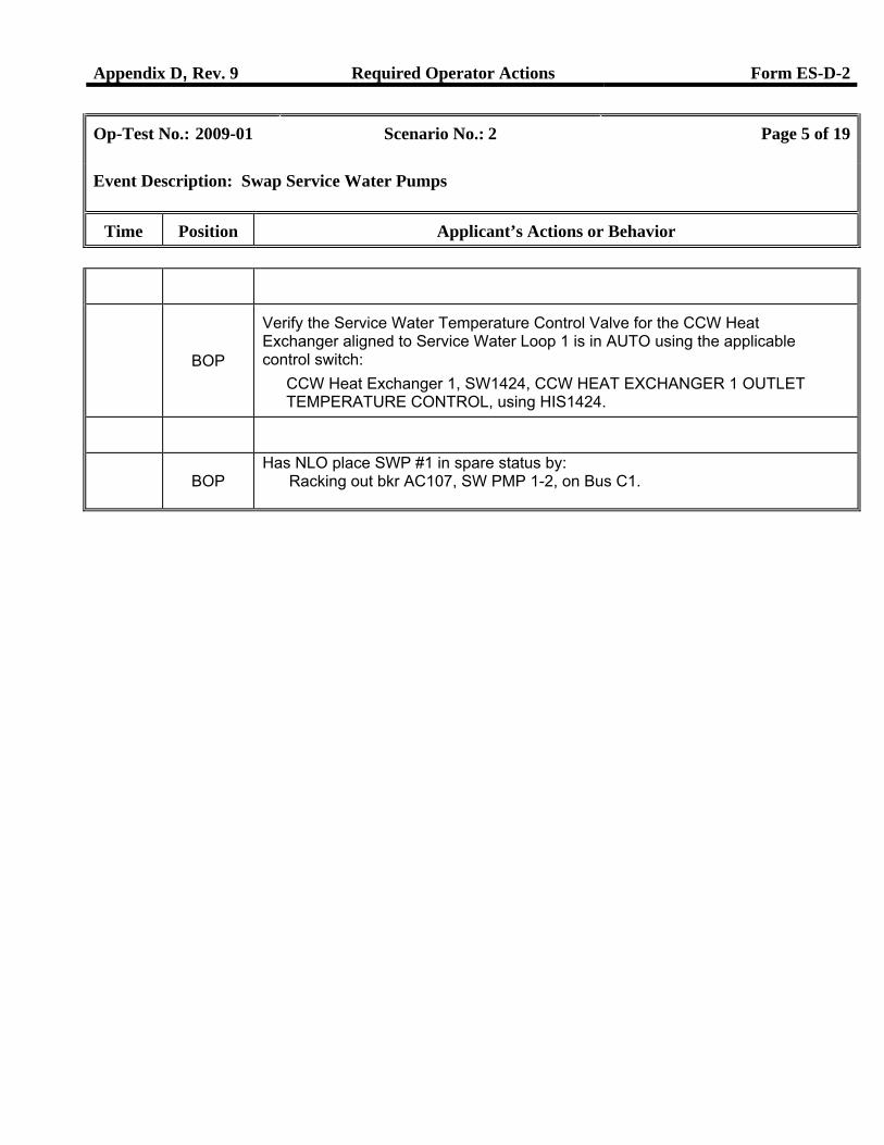
BOP
Verify the Service Water Temperature Control Valve for the CCW Heat Exchanger aligned to Service Water Loop 1 is in AUTO using the applicable control switch:
CCW Heat Exchanger 1, SW1424, CCW HEAT EXCHANGER 1 OUTLET TEMPERATURE CONTROL, using HIS1424.
BOP
Has NLO place SWP #1 in spare status by: Racking out bkr AC107, SW PMP 1-2, on Bus C1.
Appendix D, Rev. 9 Required Operator Actions Form ES-D-2
Op-Test No.: 2009-01 Scenario No.: 2 Page 6 of 19
Event Description: Pressurizer level (LT-RC14-1) Fails Low
Time Position Applicant’s Actions or Behavior
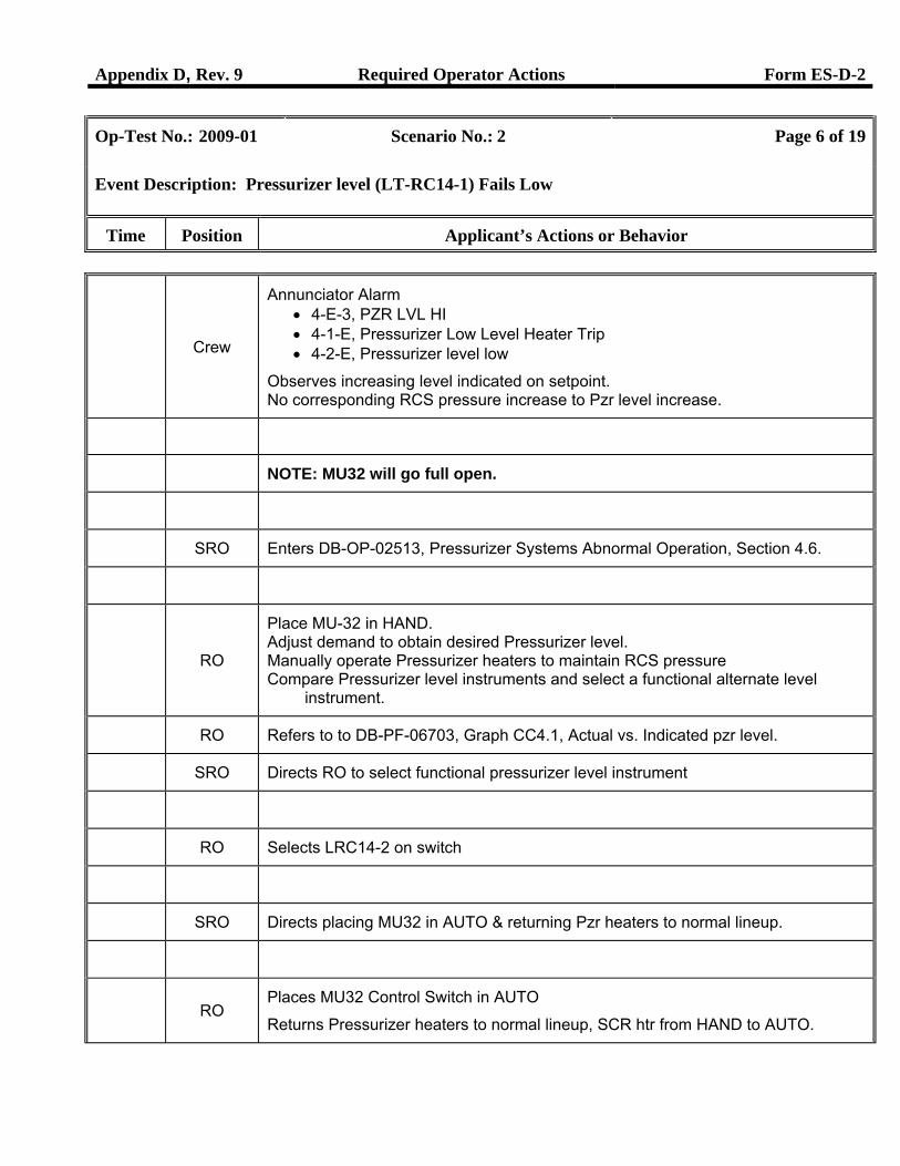
Crew
Annunciator Alarm • 4-E-3, PZR LVL HI • 4-1-E, Pressurizer Low Level Heater Trip • 4-2-E, Pressurizer level low
Observes increasing level indicated on setpoint. No corresponding RCS pressure increase to Pzr level increase.
NOTE: MU32 will go full open.
SRO Enters DB-OP-02513, Pressurizer Systems Abnormal Operation, Section 4.6.
RO
Place MU-32 in HAND. Adjust demand to obtain desired Pressurizer level. Manually operate Pressurizer heaters to maintain RCS pressure Compare Pressurizer level instruments and select a functional alternate level
instrument.
RO Refers to to DB-PF-06703, Graph CC4.1, Actual vs. Indicated pzr level.
SRO Directs RO to select functional pressurizer level instrument
RO Selects LRC14-2 on switch
SRO Directs placing MU32 in AUTO & returning Pzr heaters to normal lineup.
RO
Places MU32 Control Switch in AUTO
Returns Pressurizer heaters to normal lineup, SCR htr from HAND to AUTO.
Appendix D, Rev. 9 Required Operator Actions Form ES-D-2
Op-Test No.: 2009-01 Scenario No.: 2 Page 7 of 19
Event Description: Pressurizer level (LT-RC14-1) Fails Low
Time Position Applicant’s Actions or Behavior
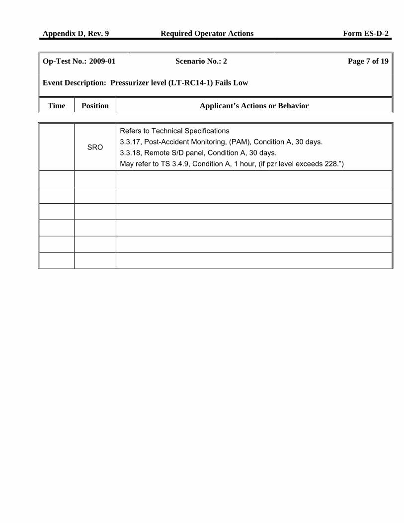
SRO
Refers to Technical Specifications 3.3.17, Post-Accident Monitoring, (PAM), Condition A, 30 days. 3.3.18, Remote S/D panel, Condition A, 30 days. May refer to TS 3.4.9, Condition A, 1 hour, (if pzr level exceeds 228.”)
Appendix D, Rev. 9 Required Operator Actions Form ES-D-2
Op-Test No.: 2009-01 Scenario No.: 2 Page 8 of 19
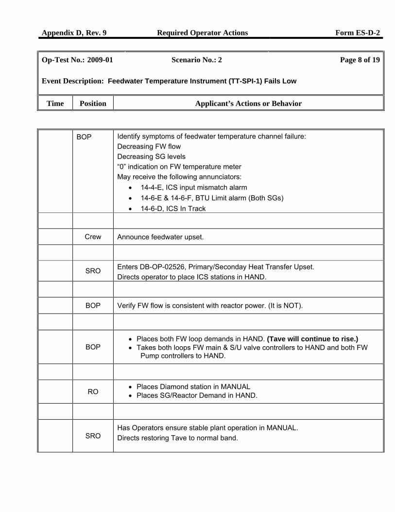
Event Description: Feedwater Temperature Instrument (TT-SPI-1) Fails Low
Time Position Applicant’s Actions or Behavior
BOP Identify symptoms of feedwater temperature channel failure: Decreasing FW flow Decreasing SG levels “0” indication on FW temperature meter May receive the following annunciators:
• 14-4-E, ICS input mismatch alarm • 14-6-E & 14-6-F, BTU Limit alarm (Both SGs) • 14-6-D, ICS In Track
Crew Announce feedwater upset.
SRO Enters DB-OP-02526, Primary/Seconday Heat Transfer Upset. Directs operator to place ICS stations in HAND.
BOP Verify FW flow is consistent with reactor power. (It is NOT).
BOP
• Places both FW loop demands in HAND. (Tave will continue to rise.) • Takes both loops FW main & S/U valve controllers to HAND and both FW
Pump controllers to HAND.
RO
• Places Diamond station in MANUAL • Places SG/Reactor Demand in HAND.
SRO
Has Operators ensure stable plant operation in MANUAL. Directs restoring Tave to normal band.
Appendix D, Rev. 9 Required Operator Actions Form ES-D-2
Op-Test No.: 2009-01 Scenario No.: 2 Page 9 of 19
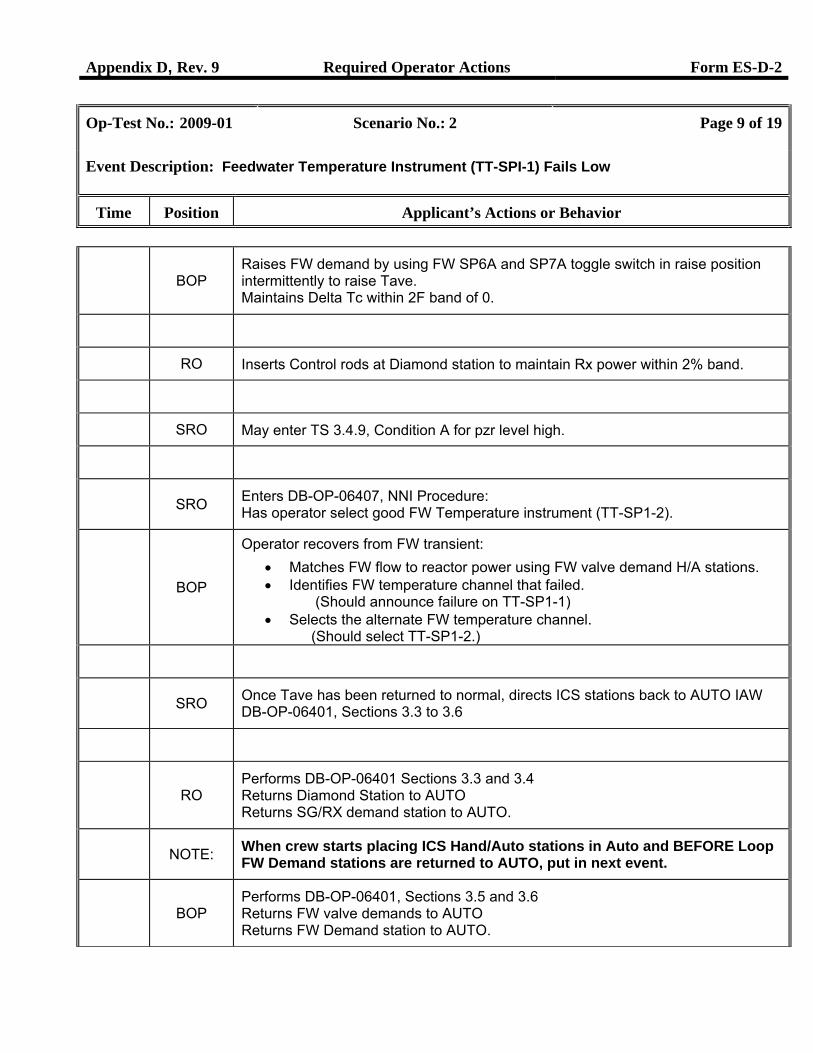
Event Description: Feedwater Temperature Instrument (TT-SPI-1) Fails Low
Time Position Applicant’s Actions or Behavior
BOP
Raises FW demand by using FW SP6A and SP7A toggle switch in raise position intermittently to raise Tave. Maintains Delta Tc within 2F band of 0.
RO Inserts Control rods at Diamond station to maintain Rx power within 2% band.
SRO May enter TS 3.4.9, Condition A for pzr level high.
SRO Enters DB-OP-06407, NNI Procedure:
Has operator select good FW Temperature instrument (TT-SP1-2).
BOP
Operator recovers from FW transient: • Matches FW flow to reactor power using FW valve demand H/A stations. • Identifies FW temperature channel that failed.
(Should announce failure on TT-SP1-1) • Selects the alternate FW temperature channel.
(Should select TT-SP1-2.)
SRO Once Tave has been returned to normal, directs ICS stations back to AUTO IAW
DB-OP-06401, Sections 3.3 to 3.6
RO
Performs DB-OP-06401 Sections 3.3 and 3.4 Returns Diamond Station to AUTO Returns SG/RX demand station to AUTO.
NOTE: When crew starts placing ICS Hand/Auto stations in Auto and BEFORE Loop
FW Demand stations are returned to AUTO, put in next event.
BOP
Performs DB-OP-06401, Sections 3.5 and 3.6 Returns FW valve demands to AUTO Returns FW Demand station to AUTO.
Appendix D, Rev. 9 Required Operator Actions Form ES-D-2
Op-Test No.: 2009-01 Scenario No.: 2 Page 10 of 19
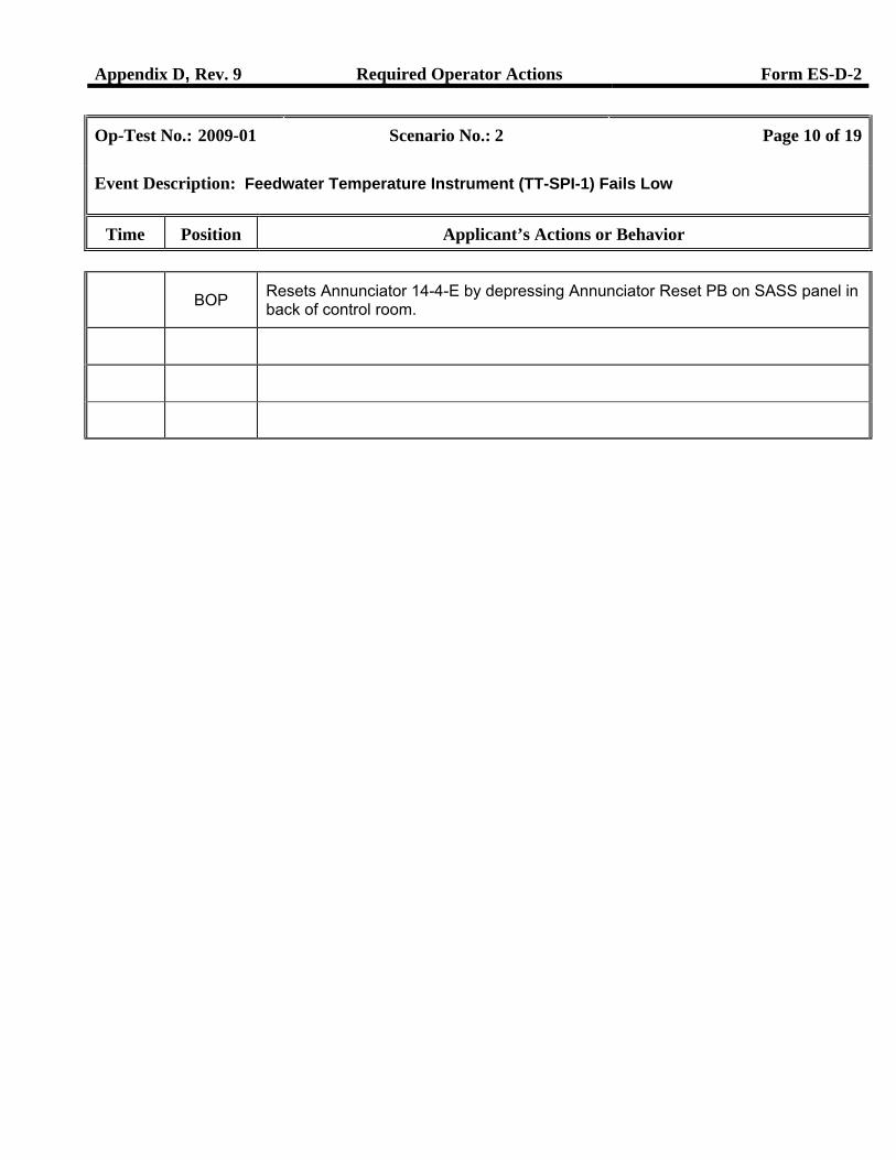
Event Description: Feedwater Temperature Instrument (TT-SPI-1) Fails Low
Time Position Applicant’s Actions or Behavior
BOP Resets Annunciator 14-4-E by depressing Annunciator Reset PB on SASS panel in
back of control room.
Appendix D, Rev. 9 Required Operator Actions Form ES-D-2
Op-Test No.: 2009-01 Scenario No.: 2 Page 11 of 19
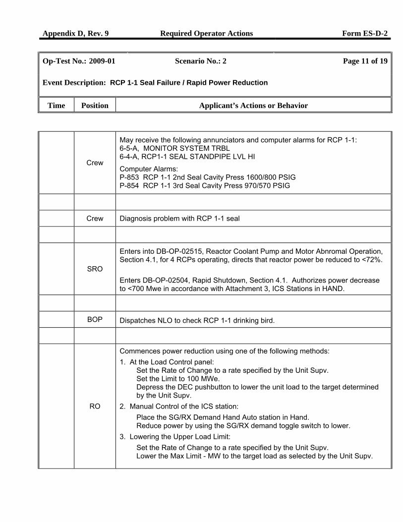
Event Description: RCP 1-1 Seal Failure / Rapid Power Reduction
Time Position Applicant’s Actions or Behavior
Crew
May receive the following annunciators and computer alarms for RCP 1-1: 6-5-A, MONITOR SYSTEM TRBL 6-4-A, RCP1-1 SEAL STANDPIPE LVL HI
Computer Alarms: P-853 RCP 1-1 2nd Seal Cavity Press 1600/800 PSIG P-854 RCP 1-1 3rd Seal Cavity Press 970/570 PSIG
Crew Diagnosis problem with RCP 1-1 seal
SRO
Enters into DB-OP-02515, Reactor Coolant Pump and Motor Abnromal Operation, Section 4.1, for 4 RCPs operating, directs that reactor power be reduced to <72%. Enters DB-OP-02504, Rapid Shutdown, Section 4.1. Authorizes power decrease to <700 Mwe in accordance with Attachment 3, ICS Stations in HAND.
BOP Dispatches NLO to check RCP 1-1 drinking bird.
RO
Commences power reduction using one of the following methods: 1. At the Load Control panel:
Set the Rate of Change to a rate specified by the Unit Supv. Set the Limit to 100 MWe. Depress the DEC pushbutton to lower the unit load to the target determined by the Unit Supv.
2. Manual Control of the ICS station: Place the SG/RX Demand Hand Auto station in Hand. Reduce power by using the SG/RX demand toggle switch to lower.
3. Lowering the Upper Load Limit: Set the Rate of Change to a rate specified by the Unit Supv. Lower the Max Limit - MW to the target load as selected by the Unit Supv.
Appendix D, Rev. 9 Required Operator Actions Form ES-D-2
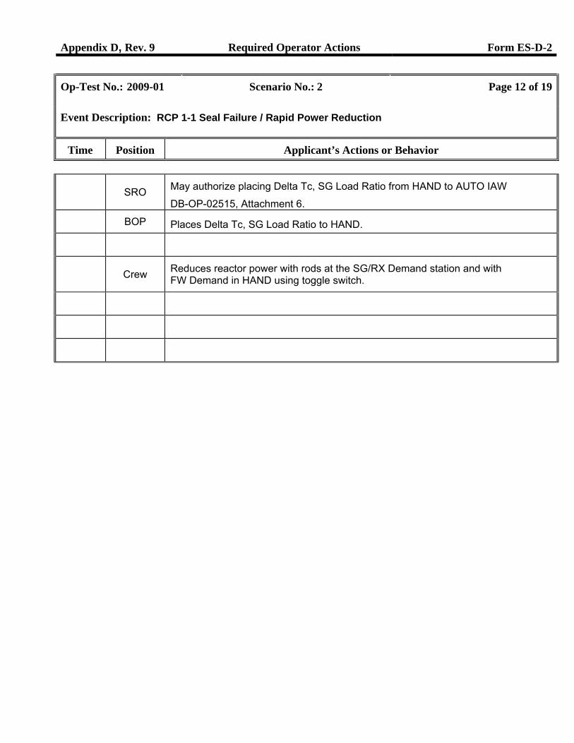
Op-Test No.: 2009-01 Scenario No.: 2 Page 12 of 19
Event Description: RCP 1-1 Seal Failure / Rapid Power Reduction
Time Position Applicant’s Actions or Behavior
SRO May authorize placing Delta Tc, SG Load Ratio from HAND to AUTO IAW
DB-OP-02515, Attachment 6. BOP Places Delta Tc, SG Load Ratio to HAND.
Crew Reduces reactor power with rods at the SG/RX Demand station and with
FW Demand in HAND using toggle switch.
Appendix D, Rev. 9 Required Operator Actions Form ES-D-2
Op-Test No.: 2009-01 Scenario No.: 2 Page 13 of 19
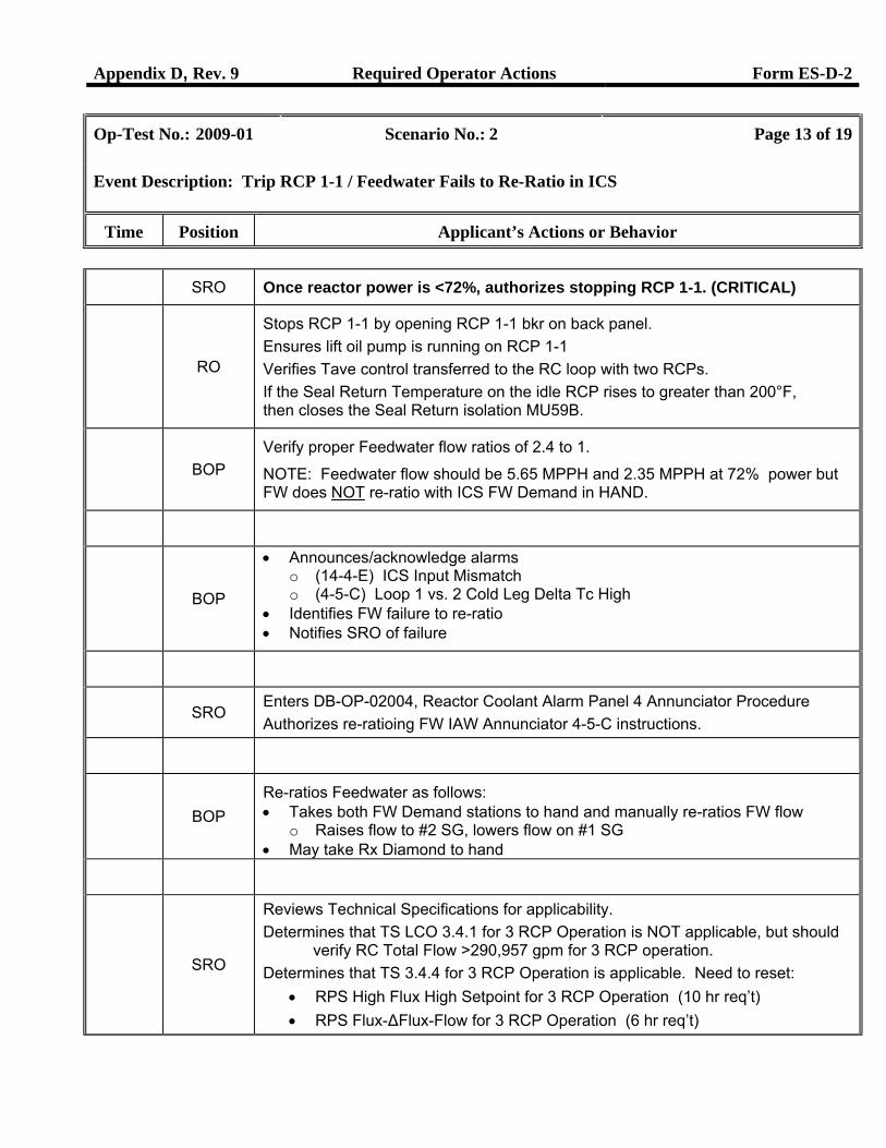
Event Description: Trip RCP 1-1 / Feedwater Fails to Re-Ratio in ICS
Time Position Applicant’s Actions or Behavior
SRO Once reactor power is <72%, authorizes stopping RCP 1-1. (CRITICAL)
RO
Stops RCP 1-1 by opening RCP 1-1 bkr on back panel. Ensures lift oil pump is running on RCP 1-1 Verifies Tave control transferred to the RC loop with two RCPs. If the Seal Return Temperature on the idle RCP rises to greater than 200°F, then closes the Seal Return isolation MU59B.
BOP Verify proper Feedwater flow ratios of 2.4 to 1.
NOTE: Feedwater flow should be 5.65 MPPH and 2.35 MPPH at 72% power but FW does NOT re-ratio with ICS FW Demand in HAND.
BOP
• Announces/acknowledge alarms o (14-4-E) ICS Input Mismatch o (4-5-C) Loop 1 vs. 2 Cold Leg Delta Tc High
• Identifies FW failure to re-ratio • Notifies SRO of failure
SRO
Enters DB-OP-02004, Reactor Coolant Alarm Panel 4 Annunciator Procedure Authorizes re-ratioing FW IAW Annunciator 4-5-C instructions.
BOP
Re-ratios Feedwater as follows: • Takes both FW Demand stations to hand and manually re-ratios FW flow
o Raises flow to #2 SG, lowers flow on #1 SG • May take Rx Diamond to hand
SRO
Reviews Technical Specifications for applicability. Determines that TS LCO 3.4.1 for 3 RCP Operation is NOT applicable, but should
verify RC Total Flow >290,957 gpm for 3 RCP operation. Determines that TS 3.4.4 for 3 RCP Operation is applicable. Need to reset:
• RPS High Flux High Setpoint for 3 RCP Operation (10 hr req’t) • RPS Flux-ΔFlux-Flow for 3 RCP Operation (6 hr req’t)
Appendix D, Rev. 9 Required Operator Actions Form ES-D-2
Op-Test No.: 2009-01 Scenario No.: 2 Page 14 of 19
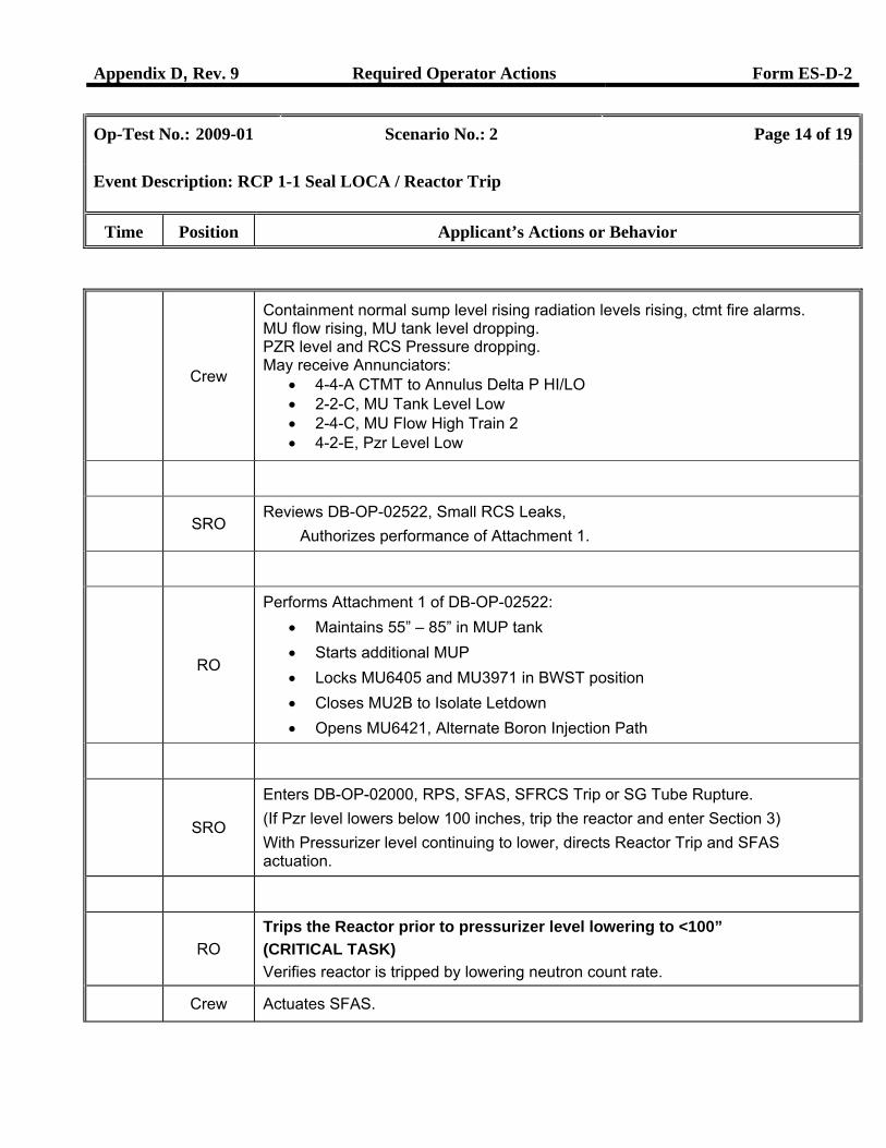
Event Description: RCP 1-1 Seal LOCA / Reactor Trip
Time Position Applicant’s Actions or Behavior
Crew
Containment normal sump level rising radiation levels rising, ctmt fire alarms. MU flow rising, MU tank level dropping. PZR level and RCS Pressure dropping. May receive Annunciators:
• 4-4-A CTMT to Annulus Delta P HI/LO • 2-2-C, MU Tank Level Low • 2-4-C, MU Flow High Train 2 • 4-2-E, Pzr Level Low
SRO
Reviews DB-OP-02522, Small RCS Leaks, Authorizes performance of Attachment 1.
RO
Performs Attachment 1 of DB-OP-02522: • Maintains 55” – 85” in MUP tank • Starts additional MUP • Locks MU6405 and MU3971 in BWST position • Closes MU2B to Isolate Letdown • Opens MU6421, Alternate Boron Injection Path
SRO
Enters DB-OP-02000, RPS, SFAS, SFRCS Trip or SG Tube Rupture. (If Pzr level lowers below 100 inches, trip the reactor and enter Section 3) With Pressurizer level continuing to lower, directs Reactor Trip and SFAS actuation.
RO
Trips the Reactor prior to pressurizer level lowering to <100” (CRITICAL TASK) Verifies reactor is tripped by lowering neutron count rate.
Crew Actuates SFAS.
2Appendix D, Rev. 9 Required Operator Actions Form ES-D-2
Op-Test No.: 2009-01 Scenario No.: 2 Page 15 of 19
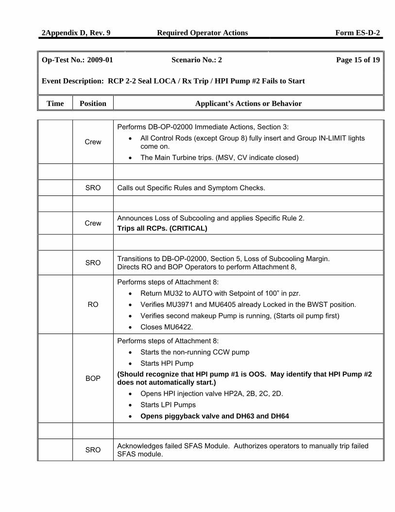
Event Description: RCP 2-2 Seal LOCA / Rx Trip / HPI Pump #2 Fails to Start
Time Position Applicant’s Actions or Behavior
Crew
Performs DB-OP-02000 Immediate Actions, Section 3: • All Control Rods (except Group 8) fully insert and Group IN-LIMIT lights
come on. • The Main Turbine trips. (MSV, CV indicate closed)
SRO Calls out Specific Rules and Symptom Checks.
Crew Announces Loss of Subcooling and applies Specific Rule 2. Trips all RCPs. (CRITICAL)
SRO Transitions to DB-OP-02000, Section 5, Loss of Subcooling Margin.
Directs RO and BOP Operators to perform Attachment 8,
RO
Performs steps of Attachment 8: • Return MU32 to AUTO with Setpoint of 100” in pzr. • Verifies MU3971 and MU6405 already Locked in the BWST position. • Verifies second makeup Pump is running, (Starts oil pump first) • Closes MU6422.
BOP
Performs steps of Attachment 8: • Starts the non-running CCW pump • Starts HPI Pump
(Should recognize that HPI pump #1 is OOS. May identify that HPI Pump #2 does not automatically start.)
• Opens HPI injection valve HP2A, 2B, 2C, 2D. • Starts LPI Pumps • Opens piggyback valve and DH63 and DH64
SRO Acknowledges failed SFAS Module. Authorizes operators to manually trip failed SFAS module.
2Appendix D, Rev. 9 Required Operator Actions Form ES-D-2
Op-Test No.: 2009-01 Scenario No.: 2 Page 16 of 19
Event Description: RCP 2-2 Seal LOCA / Rx Trip / HPI Pump #2 Fails to Start
Time Position Applicant’s Actions or Behavior
Crew
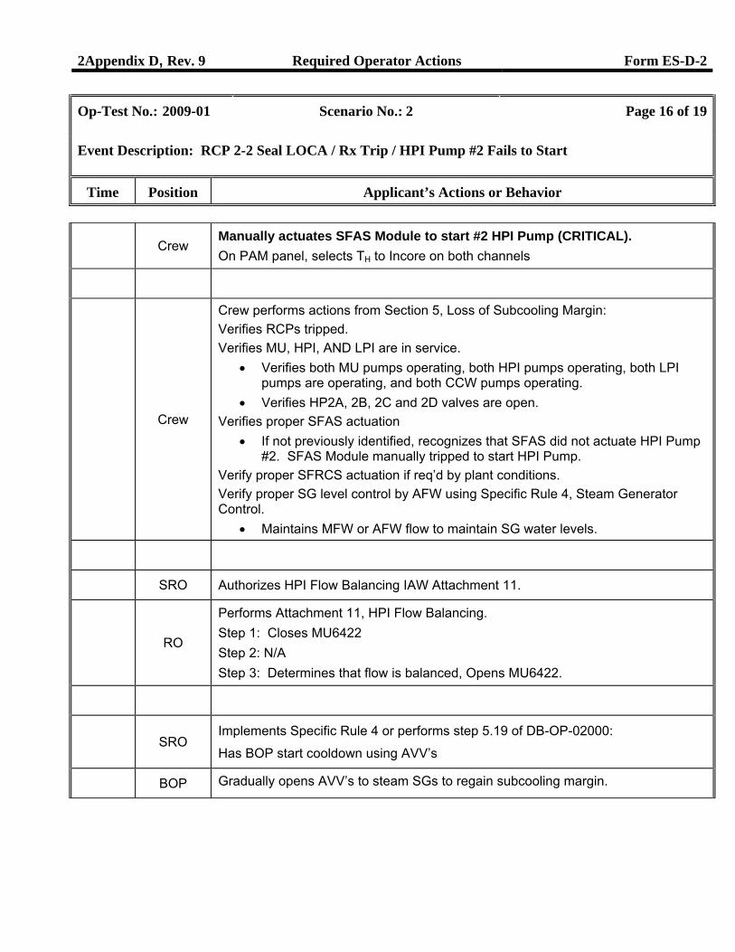
Manually actuates SFAS Module to start #2 HPI Pump (CRITICAL). On PAM panel, selects TH to Incore on both channels
Crew
Crew performs actions from Section 5, Loss of Subcooling Margin: Verifies RCPs tripped. Verifies MU, HPI, AND LPI are in service.
• Verifies both MU pumps operating, both HPI pumps operating, both LPI pumps are operating, and both CCW pumps operating.
• Verifies HP2A, 2B, 2C and 2D valves are open. Verifies proper SFAS actuation
• If not previously identified, recognizes that SFAS did not actuate HPI Pump #2. SFAS Module manually tripped to start HPI Pump.
Verify proper SFRCS actuation if req’d by plant conditions. Verify proper SG level control by AFW using Specific Rule 4, Steam Generator Control.
• Maintains MFW or AFW flow to maintain SG water levels.
SRO Authorizes HPI Flow Balancing IAW Attachment 11.
RO
Performs Attachment 11, HPI Flow Balancing. Step 1: Closes MU6422 Step 2: N/A Step 3: Determines that flow is balanced, Opens MU6422.
SRO
Implements Specific Rule 4 or performs step 5.19 of DB-OP-02000:
Has BOP start cooldown using AVV’s
BOP Gradually opens AVV’s to steam SGs to regain subcooling margin.
2Appendix D, Rev. 9 Required Operator Actions Form ES-D-2
Op-Test No.: 2009-01 Scenario No.: 2 Page 17 of 19
Event Description: RCP 2-2 Seal LOCA / Rx Trip / HPI Pump #2 Fails to Start
Time Position Applicant’s Actions or Behavior
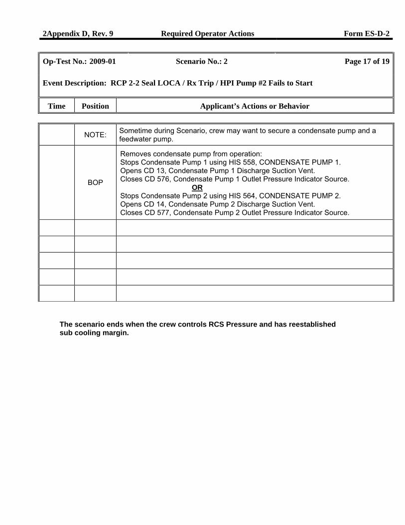
NOTE: Sometime during Scenario, crew may want to secure a condensate pump and a feedwater pump.
BOP
Removes condensate pump from operation: Stops Condensate Pump 1 using HIS 558, CONDENSATE PUMP 1. Opens CD 13, Condensate Pump 1 Discharge Suction Vent. Closes CD 576, Condensate Pump 1 Outlet Pressure Indicator Source.
OR Stops Condensate Pump 2 using HIS 564, CONDENSATE PUMP 2. Opens CD 14, Condensate Pump 2 Discharge Suction Vent. Closes CD 577, Condensate Pump 2 Outlet Pressure Indicator Source.
The scenario ends when the crew controls RCS Pressure and has reestablished sub cooling margin.
Appendix D, Rev. 9 Scenario Critical Tasks Form ES-D-1
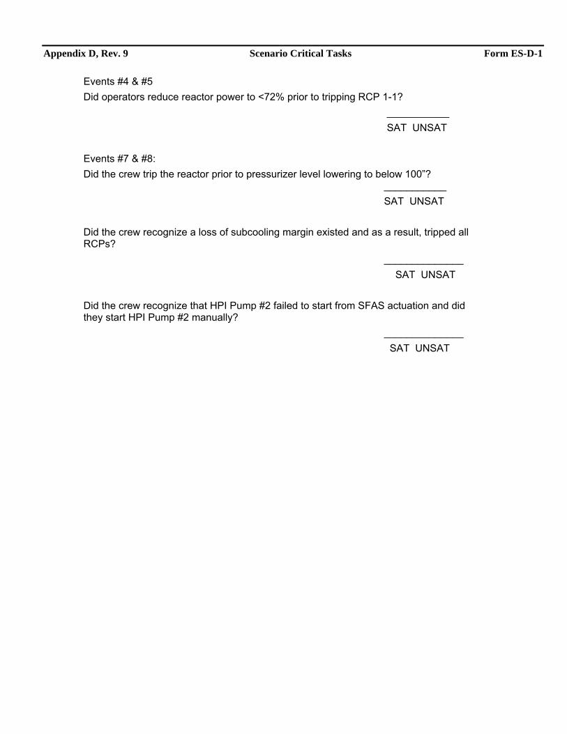
Events #4 & #5 Did operators reduce reactor power to <72% prior to tripping RCP 1-1?
___________ SAT UNSAT Events #7 & #8: Did the crew trip the reactor prior to pressurizer level lowering to below 100”? ___________ SAT UNSAT Did the crew recognize a loss of subcooling margin existed and as a result, tripped all RCPs? ______________ SAT UNSAT Did the crew recognize that HPI Pump #2 failed to start from SFAS actuation and did they start HPI Pump #2 manually? ______________ SAT UNSAT
Appendix D, Rev. 9 Form ES-D-1
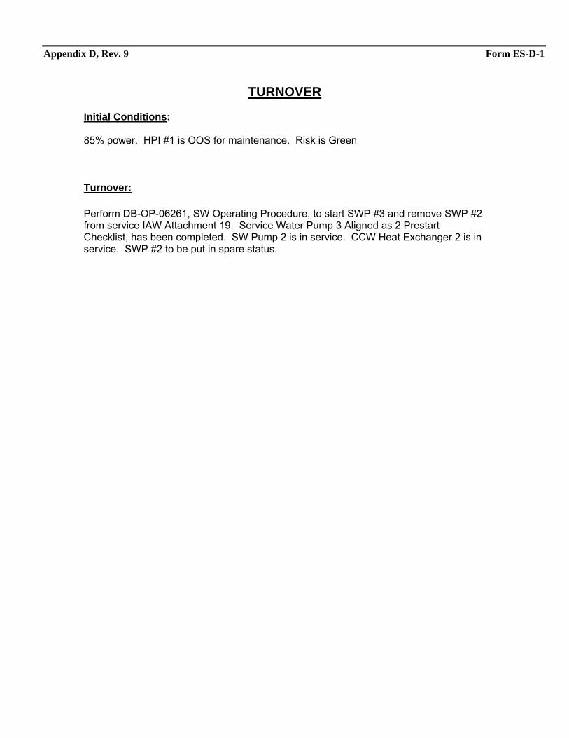
TURNOVER Initial Conditions: 85% power. HPI #1 is OOS for maintenance. Risk is Green
Turnover: Perform DB-OP-06261, SW Operating Procedure, to start SWP #3 and remove SWP #2 from service IAW Attachment 19. Service Water Pump 3 Aligned as 2 Prestart Checklist, has been completed. SW Pump 2 is in service. CCW Heat Exchanger 2 is in service. SWP #2 to be put in spare status.
Appendix D, Rev. 9 Scenario Outline Form ES-D-1
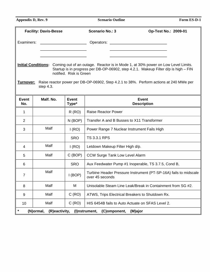
Facility: Davis-Besse Scenario No.: 3 Op-Test No.: 2009-01 Examiners: Operators:
Initial Conditions: Coming out of an outage. Reactor is in Mode 1, at 30% power on Low Level Limits.
Startup is in progress per DB-OP-06902, step 4.2.1. Makeup Filter d/p is high – FIN notified. Risk is Green
Turnover: Raise reactor power per DB-OP-06902, Step 4.2.1 to 38%. Perform actions at 240 MWe per step 4.3.
Event No.
Malf. No. Event Type*
Event Description
1 R (RO) Raise Reactor Power
2 N (BOP) Transfer A and B Busses to X11 Transformer
3 Malf I (RO) Power Range 7 Nuclear Instrument Fails High
SRO TS 3.3.1 RPS
4 Malf I (RO) Letdown Makeup Filter High d/p.
5 Malf C (BOP) CCW Surge Tank Low Level Alarm
6 SRO Aux Feedwater Pump #1 Inoperable, TS 3.7.5, Cond B,
7 Malf
I (BOP) Turbine Header Pressure Instrument (PT-SP-16A) fails to midscale over 45 seconds
8 Malf M Unisolable Steam Line Leak/Break in Containment from SG #2.
9 Malf C (RO) ATWS, Trips Electrical Breakers to Shutdown Rx.
10 Malf C (RO) HIS 6454B fails to Auto Actuate on SFAS Level 2.
* (N)ormal, (R)eactivity, (I)nstrument, (C)omponent, (M)ajor
Appendix D, Rev. 9 Scenario #3 General Description Form ES-D-1
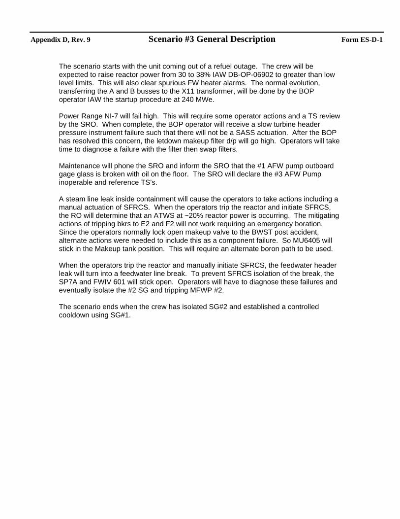
The scenario starts with the unit coming out of a refuel outage. The crew will be expected to raise reactor power from 30 to 38% IAW DB-OP-06902 to greater than low level limits. This will also clear spurious FW heater alarms. The normal evolution, transferring the A and B busses to the X11 transformer, will be done by the BOP operator IAW the startup procedure at 240 MWe. Power Range NI-7 will fail high. This will require some operator actions and a TS review by the SRO. When complete, the BOP operator will receive a slow turbine header pressure instrument failure such that there will not be a SASS actuation. After the BOP has resolved this concern, the letdown makeup filter d/p will go high. Operators will take time to diagnose a failure with the filter then swap filters. Maintenance will phone the SRO and inform the SRO that the #1 AFW pump outboard gage glass is broken with oil on the floor. The SRO will declare the #3 AFW Pump inoperable and reference TS’s. A steam line leak inside containment will cause the operators to take actions including a manual actuation of SFRCS. When the operators trip the reactor and initiate SFRCS, the RO will determine that an ATWS at ~20% reactor power is occurring. The mitigating actions of tripping bkrs to E2 and F2 will not work requiring an emergency boration. Since the operators normally lock open makeup valve to the BWST post accident, alternate actions were needed to include this as a component failure. So MU6405 will stick in the Makeup tank position. This will require an alternate boron path to be used. When the operators trip the reactor and manually initiate SFRCS, the feedwater header leak will turn into a feedwater line break. To prevent SFRCS isolation of the break, the SP7A and FWIV 601 will stick open. Operators will have to diagnose these failures and eventually isolate the #2 SG and tripping MFWP #2. The scenario ends when the crew has isolated SG#2 and established a controlled cooldown using SG#1.
Appendix D, Rev. 9 Required Operator Actions Form ES-D-2
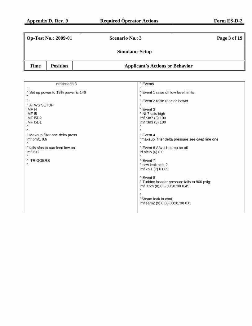
Op-Test No.: 2009-01 Scenario No.: 3 Page 3 of 19
Simulator Setup
Time Position Applicant’s Actions or Behavior
nrcsenario 3 ^ ^ Set up power to 19% power ic 146 ^ ^ ^ ATWS SETUP IMF l4 IMF l8 IMF l5D2 IMF l5D1 ^ ^ ^ Makeup filter one delta press imf bmf1 0.6 ^ ^ fails sfas to aux feed low on imf l6z2 ^ ^ TRIGGERS ^
^ Events ^ ^ Event 1 raise off low level limits ^ ^ Event 2 raise reactor Power ^ ^ Event 3 ^ NI 7 fails high imf r3n7 (3) 100 imf r3n3 (3) 100 ^ ^ ^ Event 4 ^makeup filter delta pressure see caep line one ^ ^ Event 6 Afw #1 pump no oil irf sfeib (6) 0.0 ^ ^ Event 7 ^ ccw leak side 2 imf kaj1 (7) 0.009 ^ Event 8 ^ Turbine header pressure fails to 900 psig imf l1t2n (8) 0.5 00:01:00 0.45 ^ ^ ^Steam leak in ctmt imf sam2 (9) 0.08 00:01:00 0.0
Appendix D, Rev. 9 Required Operator Actions Form ES-D-2
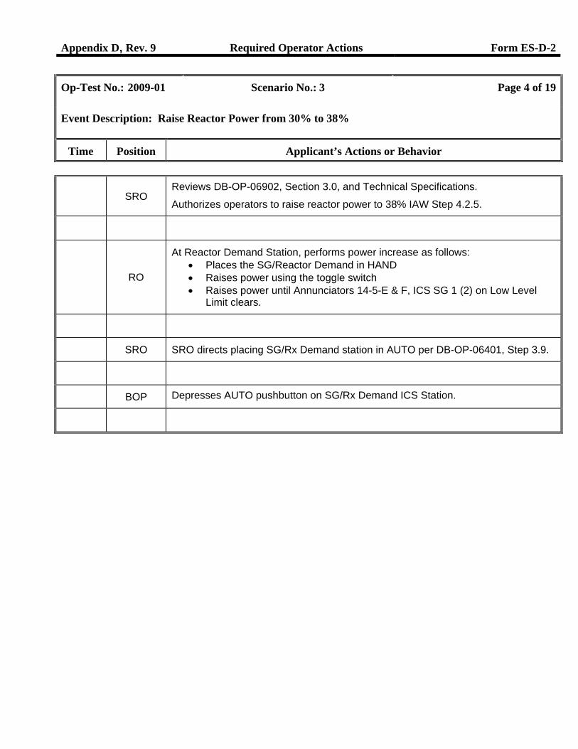
Op-Test No.: 2009-01 Scenario No.: 3 Page 4 of 19
Event Description: Raise Reactor Power from 30% to 38%
Time Position Applicant’s Actions or Behavior
SRO
Reviews DB-OP-06902, Section 3.0, and Technical Specifications.
Authorizes operators to raise reactor power to 38% IAW Step 4.2.5.
RO
At Reactor Demand Station, performs power increase as follows: • Places the SG/Reactor Demand in HAND • Raises power using the toggle switch • Raises power until Annunciators 14-5-E & F, ICS SG 1 (2) on Low Level
Limit clears.
SRO SRO directs placing SG/Rx Demand station in AUTO per DB-OP-06401, Step 3.9.
BOP Depresses AUTO pushbutton on SG/Rx Demand ICS Station.
Appendix D, Rev. 9 Required Operator Actions Form ES-D-2
Op-Test No.: 2009-01 Scenario No.: 3 Page 5 of 19
Event Description: Transfer A and B Busses to X11 Transformer
Time Position Applicant’s Actions or Behavior
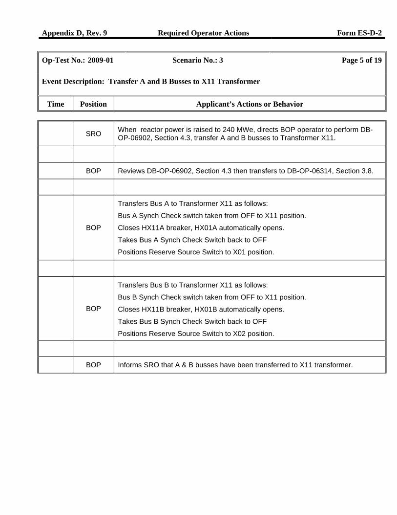
SRO When reactor power is raised to 240 MWe, directs BOP operator to perform DB-
OP-06902, Section 4.3, transfer A and B busses to Transformer X11.
BOP Reviews DB-OP-06902, Section 4.3 then transfers to DB-OP-06314, Section 3.8.
BOP
Transfers Bus A to Transformer X11 as follows:
Bus A Synch Check switch taken from OFF to X11 position.
Closes HX11A breaker, HX01A automatically opens.
Takes Bus A Synch Check Switch back to OFF
Positions Reserve Source Switch to X01 position.
BOP
Transfers Bus B to Transformer X11 as follows:
Bus B Synch Check switch taken from OFF to X11 position.
Closes HX11B breaker, HX01B automatically opens.
Takes Bus B Synch Check Switch back to OFF
Positions Reserve Source Switch to X02 position.
BOP Informs SRO that A & B busses have been transferred to X11 transformer.
Appendix D, Rev. 9 Required Operator Actions Form ES-D-2
Op-Test No.: 2009-01 Scenario No.: 3 Page 6 of 19
Event Description: Power Range NI-7 Fails High
Time Position Applicant’s Actions or Behavior
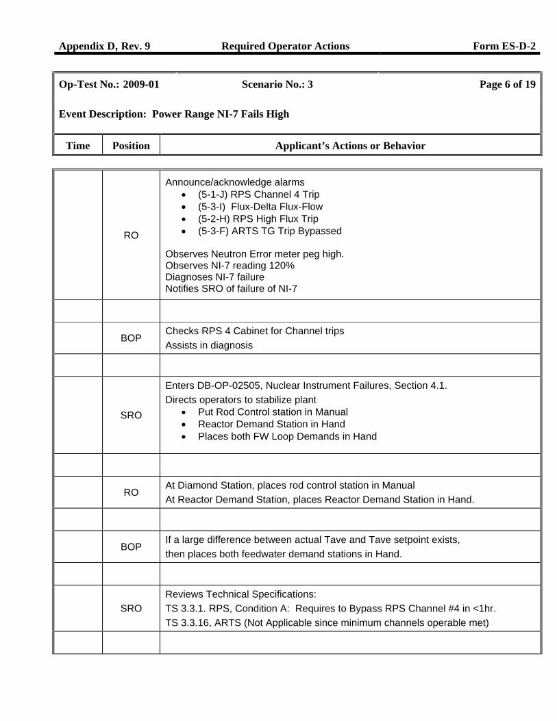
RO
Announce/acknowledge alarms • (5-1-J) RPS Channel 4 Trip • (5-3-I) Flux-Delta Flux-Flow • (5-2-H) RPS High Flux Trip • (5-3-F) ARTS TG Trip Bypassed
Observes Neutron Error meter peg high. Observes NI-7 reading 120% Diagnoses NI-7 failure Notifies SRO of failure of NI-7
BOP Checks RPS 4 Cabinet for Channel trips Assists in diagnosis
SRO
Enters DB-OP-02505, Nuclear Instrument Failures, Section 4.1. Directs operators to stabilize plant
• Put Rod Control station in Manual • Reactor Demand Station in Hand • Places both FW Loop Demands in Hand
RO At Diamond Station, places rod control station in Manual At Reactor Demand Station, places Reactor Demand Station in Hand.
BOP If a large difference between actual Tave and Tave setpoint exists, then places both feedwater demand stations in Hand.
SRO
Reviews Technical Specifications: TS 3.3.1. RPS, Condition A: Requires to Bypass RPS Channel #4 in <1hr. TS 3.3.16, ARTS (Not Applicable since minimum channels operable met)
Appendix D, Rev. 9 Required Operator Actions Form ES-D-2
Op-Test No.: 2009-01 Scenario No.: 3 Page 7 of 19
Event Description: Power Range NI-7 Fails High
Time Position Applicant’s Actions or Behavior
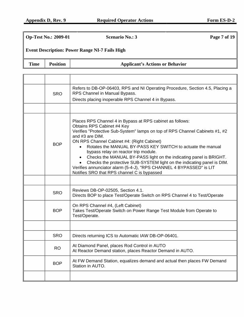
SRO
Refers to DB-OP-06403, RPS and NI Operating Procedure, Section 4.5, Placing a RPS Channel in Manual Bypass. Directs placing inoperable RPS Channel 4 in Bypass.
BOP
Places RPS Channel 4 in Bypass at RPS cabinet as follows: Obtains RPS Cabinet #4 Key Verifies "Protective Sub-System" lamps on top of RPS Channel Cabinets #1, #2 and #3 are DIM. ON RPS Channel Cabinet #4: (Right Cabinet)
• Rotates the MANUAL BY-PASS KEY SWITCH to actuate the manual bypass relay on reactor trip module.
• Checks the MANUAL BY-PASS light on the indicating panel is BRIGHT. • Checks the protective SUB-SYSTEM light on the indicating panel is DIM.
Verifies annunciator alarm (5-4-J), "RPS CHANNEL 4 BYPASSED" is LIT Notifies SRO that RPS channel C is bypassed
SRO Reviews DB-OP-02505, Section 4.1.
Directs BOP to place Test/Operate Switch on RPS Channel 4 to Test/Operate
BOP
On RPS Channel #4, (Left Cabinet) Takes Test/Operate Switch on Power Range Test Module from Operate to Test/Operate.
SRO Directs returning ICS to Automatic IAW DB-OP-06401.
RO At Diamond Panel, places Rod Control in AUTO
At Reactor Demand station, places Reactor Demand in AUTO.
BOP At FW Demand Station, equalizes demand and actual then places FW Demand
Station in AUTO.
Appendix D, Rev. 9 Required Operator Actions Form ES-D-2
Op-Test No.: 2009-01 Scenario No.: 3 Page 8 of 19
Event Description: Letdown Makeup Filter High d/p
Time Position Applicant’s Actions or Behavior
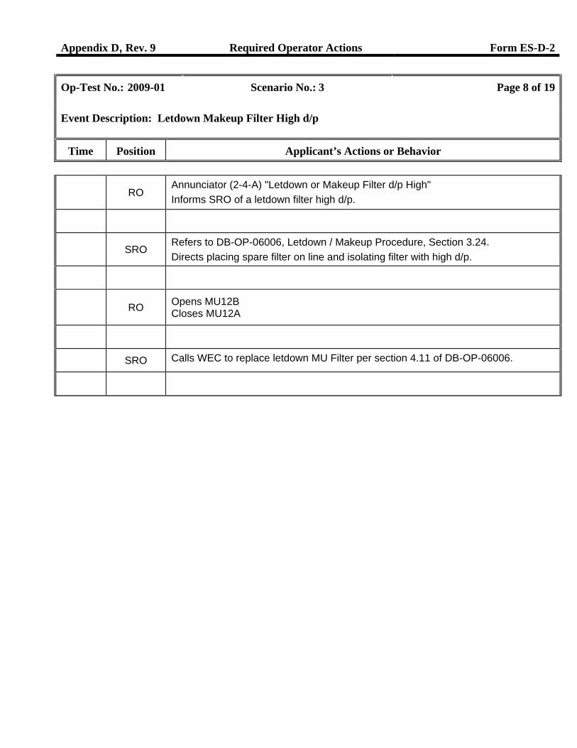
RO
Annunciator (2-4-A) "Letdown or Makeup Filter d/p High" Informs SRO of a letdown filter high d/p.
SRO
Refers to DB-OP-06006, Letdown / Makeup Procedure, Section 3.24. Directs placing spare filter on line and isolating filter with high d/p.
RO Opens MU12B
Closes MU12A
SRO Calls WEC to replace letdown MU Filter per section 4.11 of DB-OP-06006.
2Appendix D, Rev. 9 Required Operator Actions Form ES-D-2
Op-Test No.: 2009-01 Scenario No.: 3 Page 9 of 19
Event Description: CCW Surge Tank Low Level Alarm
Time Position Applicant’s Actions or Behavior
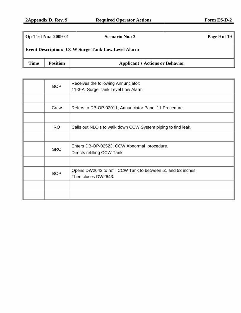
BOP
Receives the following Annunciator: 11-3-A, Surge Tank Level Low Alarm
Crew Refers to DB-OP-02011, Annunciator Panel 11 Procedure.
RO Calls out NLO’s to walk down CCW System piping to find leak.
SRO
Enters DB-OP-02523, CCW Abnormal procedure. Directs refilling CCW Tank.
BOP Opens DW2643 to refill CCW Tank to between 51 and 53 inches. Then closes DW2643.
Appendix D, Rev. 9 Required Operator Actions Form ES-D-2
Op-Test No.: 2009-01 Scenario No.: 3 Page 10 of 19
Event Description: Inoperable Aux Feedwater Pump #1
Time Position Applicant’s Actions or Behavior
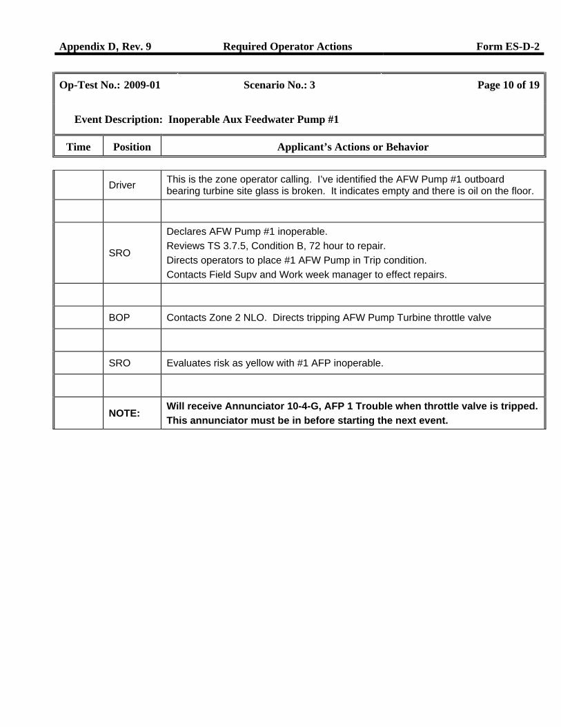
Driver This is the zone operator calling. I’ve identified the AFW Pump #1 outboard bearing turbine site glass is broken. It indicates empty and there is oil on the floor.
SRO
Declares AFW Pump #1 inoperable. Reviews TS 3.7.5, Condition B, 72 hour to repair. Directs operators to place #1 AFW Pump in Trip condition. Contacts Field Supv and Work week manager to effect repairs.
BOP Contacts Zone 2 NLO. Directs tripping AFW Pump Turbine throttle valve
SRO Evaluates risk as yellow with #1 AFP inoperable.
NOTE: Will receive Annunciator 10-4-G, AFP 1 Trouble when throttle valve is tripped. This annunciator must be in before starting the next event.
Appendix D, Rev. 9 Required Operator Actions Form ES-D-2
Op-Test No.: 2009-01 Scenario No.: 3 Page 11 of 19
Event Description: Turbine Header Pressure Instrument (PT-SP-16A) fails to midscale
Time Position Applicant’s Actions or Behavior
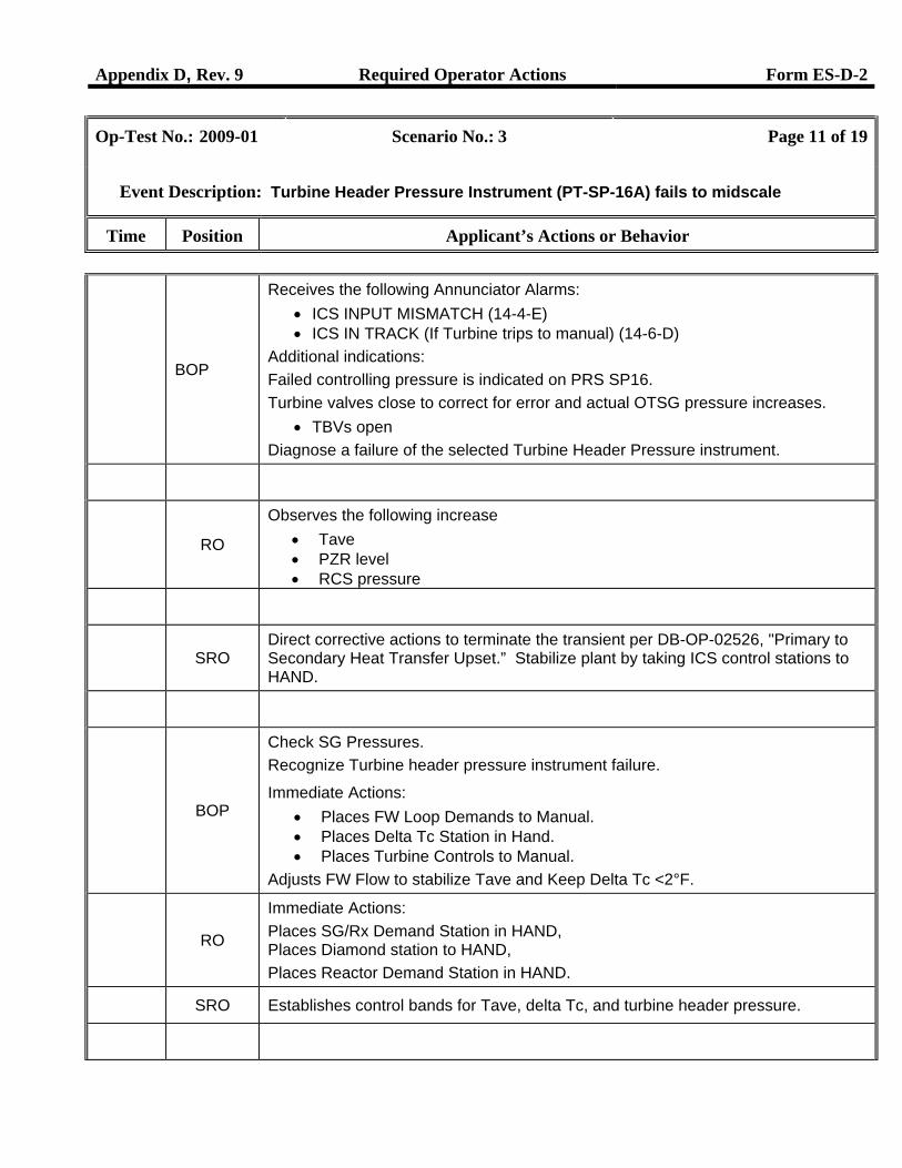
BOP
Receives the following Annunciator Alarms: • ICS INPUT MISMATCH (14-4-E) • ICS IN TRACK (If Turbine trips to manual) (14-6-D)
Additional indications: Failed controlling pressure is indicated on PRS SP16. Turbine valves close to correct for error and actual OTSG pressure increases.
• TBVs open Diagnose a failure of the selected Turbine Header Pressure instrument.
RO
Observes the following increase • Tave • PZR level • RCS pressure
SRO
Direct corrective actions to terminate the transient per DB-OP-02526, "Primary to Secondary Heat Transfer Upset.” Stabilize plant by taking ICS control stations to HAND.
BOP
Check SG Pressures. Recognize Turbine header pressure instrument failure.
Immediate Actions: • Places FW Loop Demands to Manual. • Places Delta Tc Station in Hand. • Places Turbine Controls to Manual.
Adjusts FW Flow to stabilize Tave and Keep Delta Tc <2°F.
RO
Immediate Actions: Places SG/Rx Demand Station in HAND, Places Diamond station to HAND, Places Reactor Demand Station in HAND.
SRO Establishes control bands for Tave, delta Tc, and turbine header pressure.
Appendix D, Rev. 9 Required Operator Actions Form ES-D-2
Op-Test No.: 2009-01 Scenario No.: 3 Page 12 of 19
Event Description: Turbine Header Pressure Instrument (PT-SP-16A) fails to midscale
Time Position Applicant’s Actions or Behavior
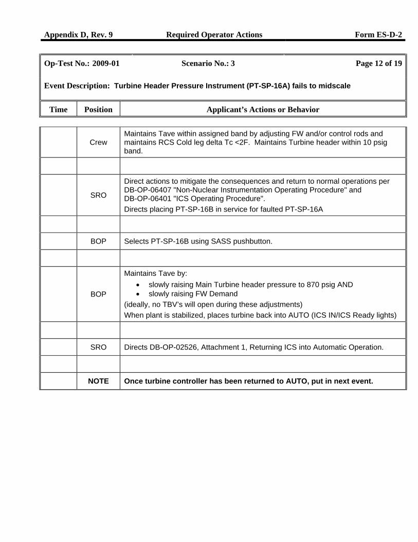
Crew
Maintains Tave within assigned band by adjusting FW and/or control rods and maintains RCS Cold leg delta Tc <2F. Maintains Turbine header within 10 psig band.
SRO
Direct actions to mitigate the consequences and return to normal operations per DB-OP-06407 "Non-Nuclear Instrumentation Operating Procedure" and DB-OP-06401 "ICS Operating Procedure". Directs placing PT-SP-16B in service for faulted PT-SP-16A
BOP Selects PT-SP-16B using SASS pushbutton.
BOP
Maintains Tave by: • slowly raising Main Turbine header pressure to 870 psig AND • slowly raising FW Demand
(ideally, no TBV’s will open during these adjustments) When plant is stabilized, places turbine back into AUTO (ICS IN/ICS Ready lights)
SRO Directs DB-OP-02526, Attachment 1, Returning ICS into Automatic Operation.
NOTE Once turbine controller has been returned to AUTO, put in next event.
Appendix D, Rev. 9 Required Operator Actions Form ES-D-2
Op-Test No.: 2009-01 Scenario No.: 3 Page 13 of 19
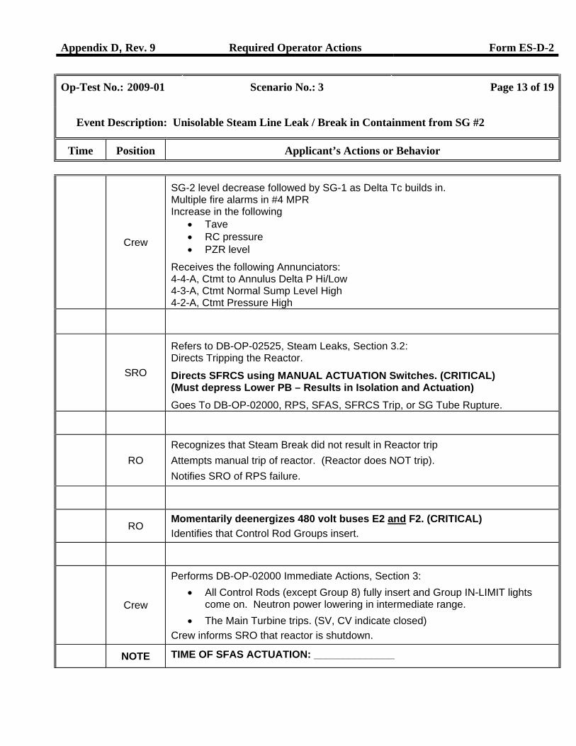
Event Description: Unisolable Steam Line Leak / Break in Containment from SG #2
Time Position Applicant’s Actions or Behavior
Crew
SG-2 level decrease followed by SG-1 as Delta Tc builds in. Multiple fire alarms in #4 MPR Increase in the following
• Tave • RC pressure • PZR level
Receives the following Annunciators: 4-4-A, Ctmt to Annulus Delta P Hi/Low 4-3-A, Ctmt Normal Sump Level High 4-2-A, Ctmt Pressure High
SRO
Refers to DB-OP-02525, Steam Leaks, Section 3.2: Directs Tripping the Reactor.
Directs SFRCS using MANUAL ACTUATION Switches. (CRITICAL) (Must depress Lower PB – Results in Isolation and Actuation) Goes To DB-OP-02000, RPS, SFAS, SFRCS Trip, or SG Tube Rupture.
RO
Recognizes that Steam Break did not result in Reactor trip Attempts manual trip of reactor. (Reactor does NOT trip). Notifies SRO of RPS failure.
RO Momentarily deenergizes 480 volt buses E2 and F2. (CRITICAL) Identifies that Control Rod Groups insert.
Crew
Performs DB-OP-02000 Immediate Actions, Section 3: • All Control Rods (except Group 8) fully insert and Group IN-LIMIT lights
come on. Neutron power lowering in intermediate range. • The Main Turbine trips. (SV, CV indicate closed)
Crew informs SRO that reactor is shutdown.
NOTE TIME OF SFAS ACTUATION: ______________
Appendix D, Rev. 9 Required Operator Actions Form ES-D-2
Op-Test No.: 2009-01 Scenario No.: 3 Page 14 of 19
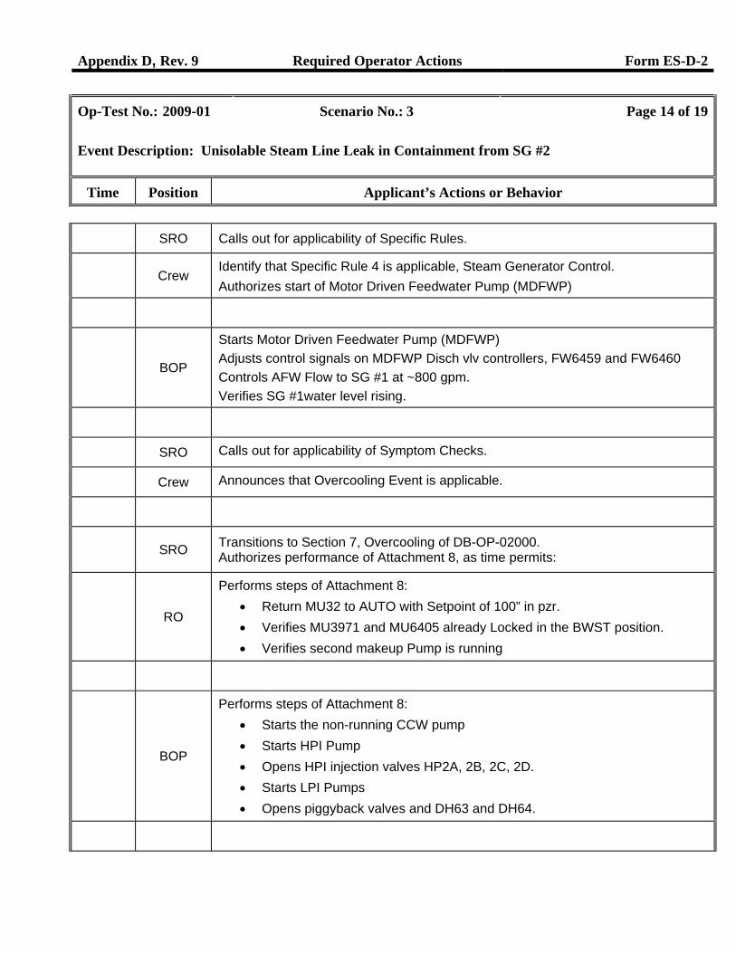
Event Description: Unisolable Steam Line Leak in Containment from SG #2
Time Position Applicant’s Actions or Behavior
SRO Calls out for applicability of Specific Rules.
Crew
Identify that Specific Rule 4 is applicable, Steam Generator Control. Authorizes start of Motor Driven Feedwater Pump (MDFWP)
BOP
Starts Motor Driven Feedwater Pump (MDFWP) Adjusts control signals on MDFWP Disch vlv controllers, FW6459 and FW6460 Controls AFW Flow to SG #1 at ~800 gpm. Verifies SG #1water level rising.
SRO Calls out for applicability of Symptom Checks.
Crew Announces that Overcooling Event is applicable.
SRO Transitions to Section 7, Overcooling of DB-OP-02000.
Authorizes performance of Attachment 8, as time permits:
RO
Performs steps of Attachment 8: • Return MU32 to AUTO with Setpoint of 100” in pzr. • Verifies MU3971 and MU6405 already Locked in the BWST position. • Verifies second makeup Pump is running
BOP
Performs steps of Attachment 8: • Starts the non-running CCW pump • Starts HPI Pump • Opens HPI injection valves HP2A, 2B, 2C, 2D. • Starts LPI Pumps • Opens piggyback valves and DH63 and DH64.
Appendix D, Rev. 9 Required Operator Actions Form ES-D-2
Op-Test No.: 2009-01 Scenario No.: 3 Page 15 of 19
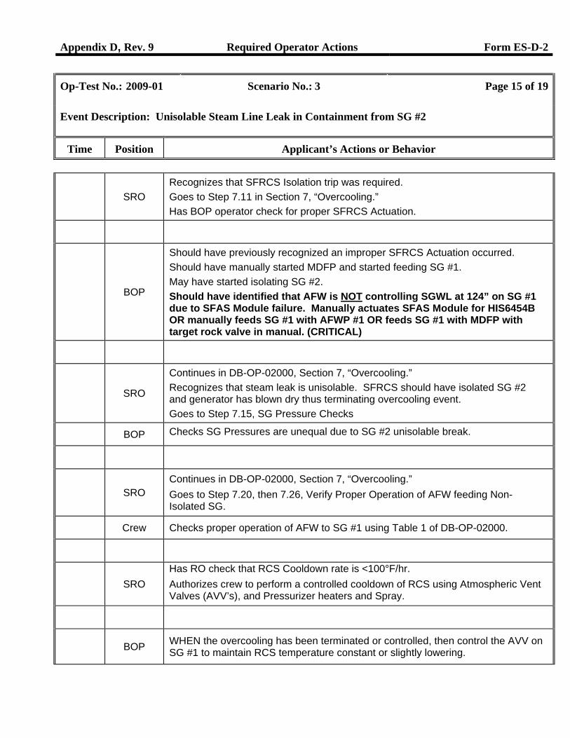
Event Description: Unisolable Steam Line Leak in Containment from SG #2
Time Position Applicant’s Actions or Behavior
SRO
Recognizes that SFRCS Isolation trip was required. Goes to Step 7.11 in Section 7, “Overcooling.” Has BOP operator check for proper SFRCS Actuation.
BOP
Should have previously recognized an improper SFRCS Actuation occurred. Should have manually started MDFP and started feeding SG #1. May have started isolating SG #2. Should have identified that AFW is NOT controlling SGWL at 124” on SG #1 due to SFAS Module failure. Manually actuates SFAS Module for HIS6454B OR manually feeds SG #1 with AFWP #1 OR feeds SG #1 with MDFP with target rock valve in manual. (CRITICAL)
SRO
Continues in DB-OP-02000, Section 7, “Overcooling.” Recognizes that steam leak is unisolable. SFRCS should have isolated SG #2 and generator has blown dry thus terminating overcooling event. Goes to Step 7.15, SG Pressure Checks
BOP Checks SG Pressures are unequal due to SG #2 unisolable break.
SRO
Continues in DB-OP-02000, Section 7, “Overcooling.” Goes to Step 7.20, then 7.26, Verify Proper Operation of AFW feeding Non-Isolated SG.
Crew Checks proper operation of AFW to SG #1 using Table 1 of DB-OP-02000.
SRO
Has RO check that RCS Cooldown rate is <100°F/hr. Authorizes crew to perform a controlled cooldown of RCS using Atmospheric Vent Valves (AVV’s), and Pressurizer heaters and Spray.
BOP WHEN the overcooling has been terminated or controlled, then control the AVV on
SG #1 to maintain RCS temperature constant or slightly lowering.
Appendix D, Rev. 9 Required Operator Actions Form ES-D-2
Op-Test No.: 2009-01 Scenario No.: 3 Page 16 of 19
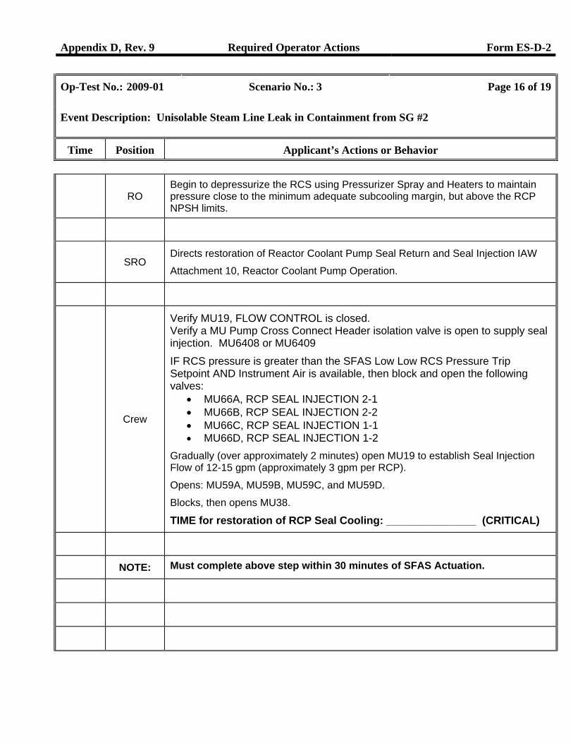
Event Description: Unisolable Steam Line Leak in Containment from SG #2
Time Position Applicant’s Actions or Behavior
RO
Begin to depressurize the RCS using Pressurizer Spray and Heaters to maintain pressure close to the minimum adequate subcooling margin, but above the RCP NPSH limits.
SRO
Directs restoration of Reactor Coolant Pump Seal Return and Seal Injection IAW
Attachment 10, Reactor Coolant Pump Operation.
Crew
Verify MU19, FLOW CONTROL is closed. Verify a MU Pump Cross Connect Header isolation valve is open to supply seal injection. MU6408 or MU6409
IF RCS pressure is greater than the SFAS Low Low RCS Pressure Trip Setpoint AND Instrument Air is available, then block and open the following valves:
• MU66A, RCP SEAL INJECTION 2-1 • MU66B, RCP SEAL INJECTION 2-2 • MU66C, RCP SEAL INJECTION 1-1 • MU66D, RCP SEAL INJECTION 1-2
Gradually (over approximately 2 minutes) open MU19 to establish Seal Injection Flow of 12-15 gpm (approximately 3 gpm per RCP).
Opens: MU59A, MU59B, MU59C, and MU59D.
Blocks, then opens MU38.
TIME for restoration of RCP Seal Cooling: _______________ (CRITICAL)
NOTE: Must complete above step within 30 minutes of SFAS Actuation.
Appendix D, Rev. 9 Required Operator Actions Form ES-D-2
Op-Test No.: 2009-01 Scenario No.: 3 Page 17 of 19
Event Description: Unisolable Steam Line Leak in Containment from SG #2
Time Position Applicant’s Actions or Behavior
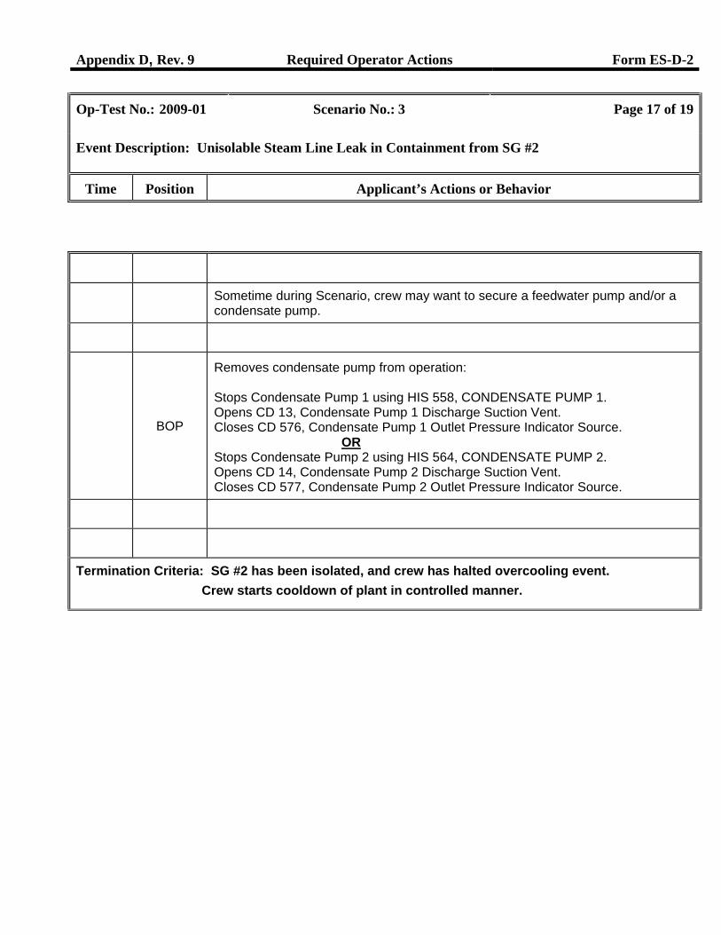
Sometime during Scenario, crew may want to secure a feedwater pump and/or a condensate pump.
BOP
Removes condensate pump from operation: Stops Condensate Pump 1 using HIS 558, CONDENSATE PUMP 1. Opens CD 13, Condensate Pump 1 Discharge Suction Vent. Closes CD 576, Condensate Pump 1 Outlet Pressure Indicator Source.
OR Stops Condensate Pump 2 using HIS 564, CONDENSATE PUMP 2. Opens CD 14, Condensate Pump 2 Discharge Suction Vent. Closes CD 577, Condensate Pump 2 Outlet Pressure Indicator Source.
Termination Criteria: SG #2 has been isolated, and crew has halted overcooling event. Crew starts cooldown of plant in controlled manner.
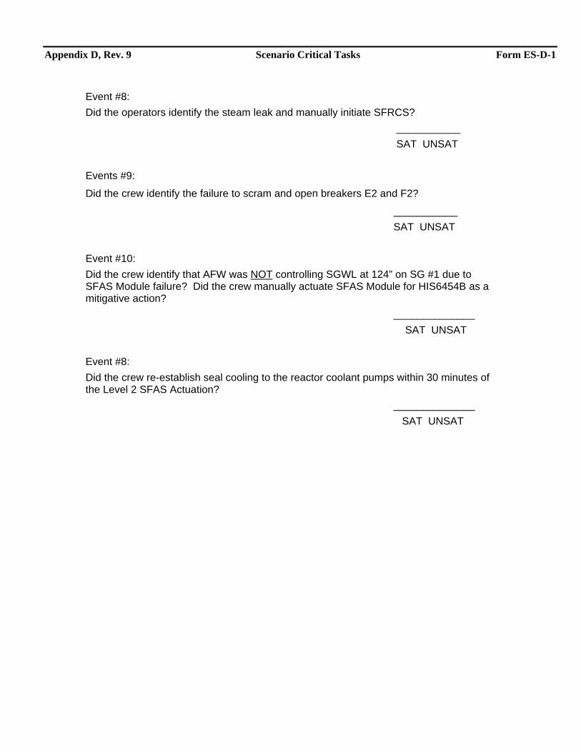
Appendix D, Rev. 9 Scenario Critical Tasks Form ES-D-1
Event #8: Did the operators identify the steam leak and manually initiate SFRCS?
___________ SAT UNSAT Events #9:
Did the crew identify the failure to scram and open breakers E2 and F2?
___________ SAT UNSAT Event #10: Did the crew identify that AFW was NOT controlling SGWL at 124” on SG #1 due to SFAS Module failure? Did the crew manually actuate SFAS Module for HIS6454B as a mitigative action? ______________ SAT UNSAT Event #8: Did the crew re-establish seal cooling to the reactor coolant pumps within 30 minutes of the Level 2 SFAS Actuation? ______________ SAT UNSAT
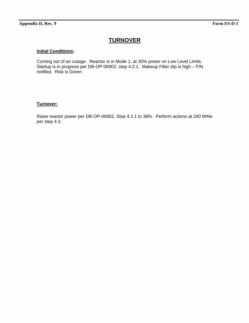
Appendix D, Rev. 9 Form ES-D-1
TURNOVER Initial Conditions: Coming out of an outage. Reactor is in Mode 1, at 30% power on Low Level Limits. Startup is in progress per DB-OP-06902, step 4.2.1. Makeup Filter d/p is high – FIN notified. Risk is Green
Turnover: Raise reactor power per DB-OP-06902, Step 4.2.1 to 38%. Perform actions at 240 MWe per step 4.3.
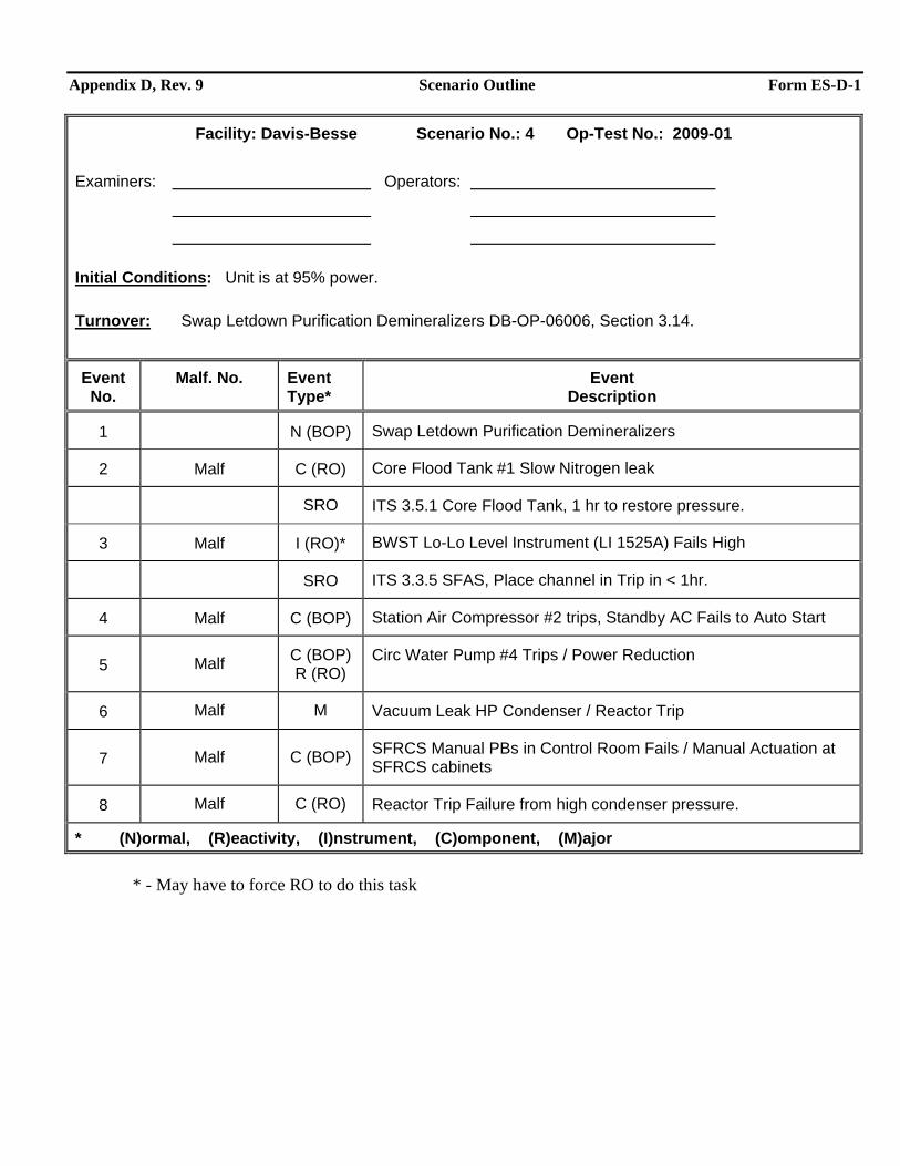
Appendix D, Rev. 9 Scenario Outline Form ES-D-1
Facility: Davis-Besse Scenario No.: 4 Op-Test No.: 2009-01 Examiners: Operators:
Initial Conditions: Unit is at 95% power.
Turnover: Swap Letdown Purification Demineralizers DB-OP-06006, Section 3.14.
Event No.
Malf. No. Event Type*
Event Description
1 N (BOP) Swap Letdown Purification Demineralizers
2 Malf C (RO) Core Flood Tank #1 Slow Nitrogen leak
SRO ITS 3.5.1 Core Flood Tank, 1 hr to restore pressure.
3 Malf I (RO)* BWST Lo-Lo Level Instrument (LI 1525A) Fails High
SRO ITS 3.3.5 SFAS, Place channel in Trip in < 1hr.
4 Malf C (BOP) Station Air Compressor #2 trips, Standby AC Fails to Auto Start
5 Malf C (BOP) R (RO)
Circ Water Pump #4 Trips / Power Reduction
6 Malf M Vacuum Leak HP Condenser / Reactor Trip
7 Malf C (BOP) SFRCS Manual PBs in Control Room Fails / Manual Actuation at SFRCS cabinets
8 Malf C (RO) Reactor Trip Failure from high condenser pressure.
* (N)ormal, (R)eactivity, (I)nstrument, (C)omponent, (M)ajor * - May have to force RO to do this task
Appendix D, Rev. 9 Scenario #4 General Description Form ES-D-1
The scenario starts with the unit at 95% power. The crew will be expected to swap letdown purification demineralizers as a Normal evolution A slow nitrogen leak on a core flood tank will result in CFT pressure lowering below its TS minimum pressure requiring actions for the operators to repressurize and requiring the SRO to review ITS 3.5.1. Similarly a BWST low-low level instrument fails high requiring SRO review of Tech Specs. Although there are minimal actions for the RO, the BOP operator must trip the SFAS instrument channel IAW ITS 3.3.5 within 1 hour. The crew will receive an annunciator indicating loss of a Station Air Compressor. The standby air compressor will fail to auto start requiring manual actions for the BOP operator to correct. Circulating water pump #4 will trip due to a breaker over current problem. This will cause condenser vacuum pressure to rise necessitating an emergent power reduction. This condition will eventually degrade into a loss of vacuum in the main condenser. The crew must trip the main turbine prior to condenser pressure rising to >7.5” and must trip the reactor prior to condenser pressure rising to >10.” A fault in the SFRCS Manual Actuation switches on the front panels will require operators to actuate SFRCS by manually realigning SFRCS equipment. The scenario ends when the crew has tripped the main turbine, tripped the reactor, and has properly aligned SFRCS manually to feed AFW and isolate BOTH SGs.
Appendix D, Rev. 9 Required Operator Actions Form ES-D-2
Op-Test No.: 2009-01 Scenario No.: 4 Page 3 of 18
Simulator Setup
Time Position Applicant’s Actions or Behavior
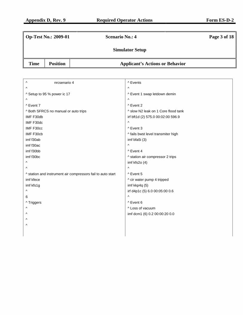
^ nrcsenario 4 ^ ^ Setup to 95 % power ic 17 ^ ^ Event 7 ^ Both SFRCS no manual or auto trips IMF F30db IMF F30dc IMF F30cc IMF F30cb imf f30ab imf f30ac imf f30bb imf f30bc ^ ^ ^ station and instrument air compressors fail to auto start imf kfece imf kfs1g ^ 6 ^ Triggers ^ ^ ^ ^
^ Events ^ ^ Event 1 swap letdown demin ^ ^ Event 2 ^ slow N2 leak on 1 Core flood tank irf bft1d (2) 575.0 00:02:00 596.9 ^ ^ Event 3 ^ fails bwst level transmiter high imf bfa5i (3) ^ ^ Event 4 ^ station air compressor 2 trips imf kfs2o (4) ^ ^ Event 5 ^ cir water pump 4 tripped imf kkp4q (5) irf d4p1c (5) 6.0 00:05:00 0.6 ^ ^ Event 6 ^ Loss of vacuum imf dcm1 (6) 0.2 00:00:20 0.0
Appendix D, Rev. 9 Required Operator Actions Form ES-D-2
Op-Test No.: 2009-01 Scenario No.: 4 Page 4 of 18
Event Description: Swap Letdown Purification Demineralizers
Time Position Applicant’s Actions or Behavior
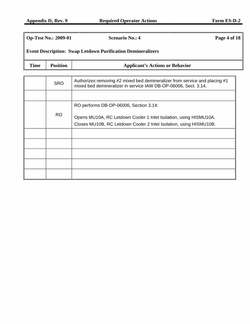
SRO Authorizes removing #2 mixed bed demineralizer from service and placing #1 mixed bed demineralizer in service IAW DB-OP-06006, Sect. 3.14.
RO
RO performs DB-OP-06006, Section 3.14: Opens MU10A, RC Letdown Cooler 1 Inlet Isolation, using HISMU10A. Closes MU10B, RC Letdown Cooler 2 Inlet Isolation, using HISMU10B.
Appendix D, Rev. 9 Required Operator Actions Form ES-D-2
Op-Test No.: 2009-01 Scenario No.: 4 Page 5 of 18
Event Description: Core Flood Tank #1 Slow Nitrogen Leak
Time Position Applicant’s Actions or Behavior
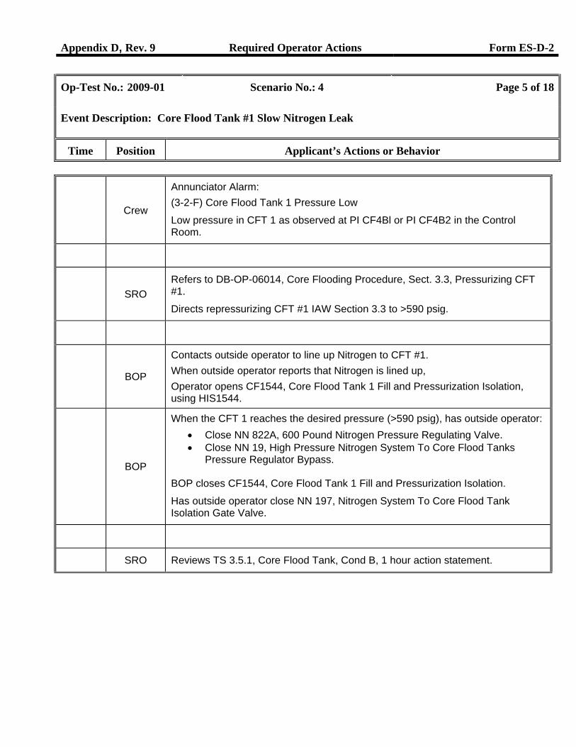
Crew
Annunciator Alarm: (3-2-F) Core Flood Tank 1 Pressure Low
Low pressure in CFT 1 as observed at PI CF4Bl or PI CF4B2 in the Control Room.
SRO
Refers to DB-OP-06014, Core Flooding Procedure, Sect. 3.3, Pressurizing CFT #1.
Directs repressurizing CFT #1 IAW Section 3.3 to >590 psig.
BOP
Contacts outside operator to line up Nitrogen to CFT #1. When outside operator reports that Nitrogen is lined up, Operator opens CF1544, Core Flood Tank 1 Fill and Pressurization Isolation, using HIS1544.
BOP
When the CFT 1 reaches the desired pressure (>590 psig), has outside operator: • Close NN 822A, 600 Pound Nitrogen Pressure Regulating Valve. • Close NN 19, High Pressure Nitrogen System To Core Flood Tanks
Pressure Regulator Bypass. BOP closes CF1544, Core Flood Tank 1 Fill and Pressurization Isolation.
Has outside operator close NN 197, Nitrogen System To Core Flood Tank Isolation Gate Valve.
SRO Reviews TS 3.5.1, Core Flood Tank, Cond B, 1 hour action statement.
Appendix D, Rev. 9 Required Operator Actions Form ES-D-2
Op-Test No.: 2009-01 Scenario No.: 4 Page 6 of 18
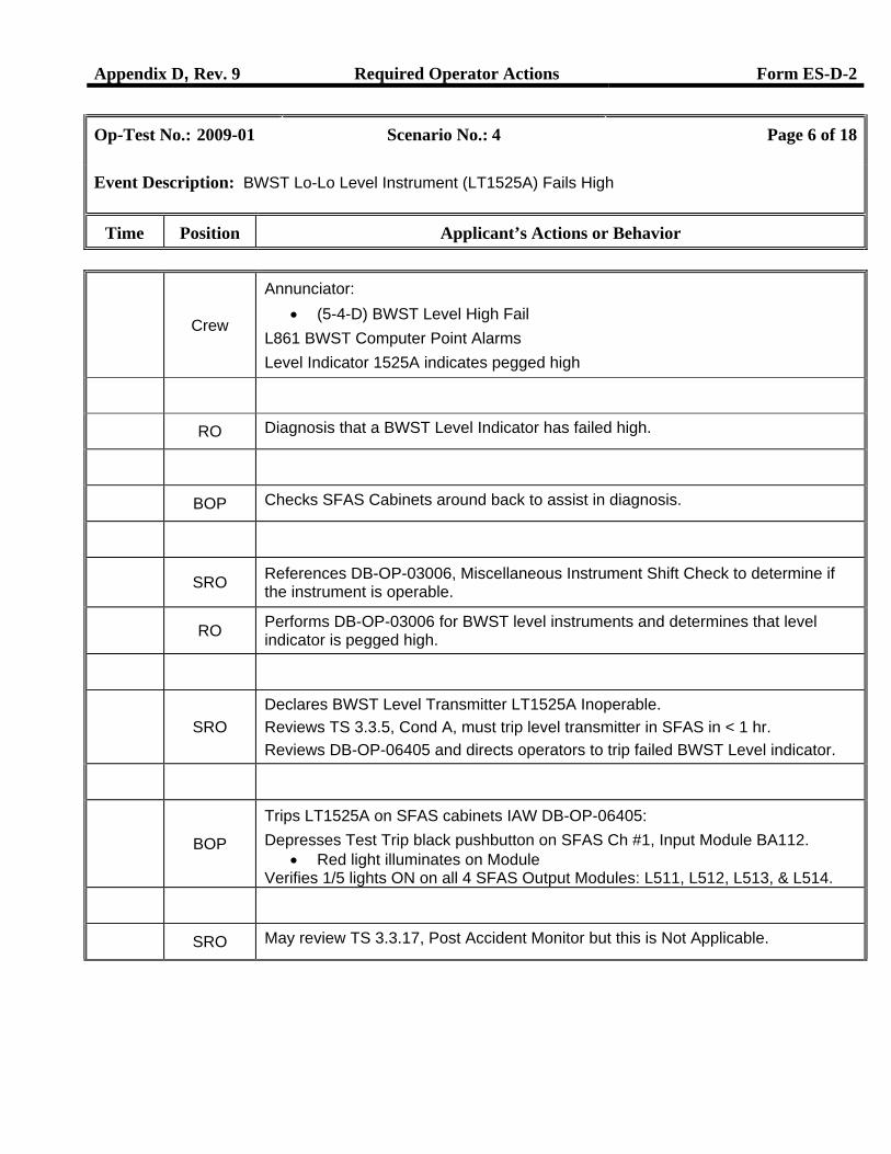
Event Description: BWST Lo-Lo Level Instrument (LT1525A) Fails High
Time Position Applicant’s Actions or Behavior
Crew
Annunciator: • (5-4-D) BWST Level High Fail
L861 BWST Computer Point Alarms Level Indicator 1525A indicates pegged high
RO Diagnosis that a BWST Level Indicator has failed high.
BOP Checks SFAS Cabinets around back to assist in diagnosis.
SRO References DB-OP-03006, Miscellaneous Instrument Shift Check to determine if the instrument is operable.
RO Performs DB-OP-03006 for BWST level instruments and determines that level indicator is pegged high.
SRO
Declares BWST Level Transmitter LT1525A Inoperable. Reviews TS 3.3.5, Cond A, must trip level transmitter in SFAS in < 1 hr. Reviews DB-OP-06405 and directs operators to trip failed BWST Level indicator.
BOP
Trips LT1525A on SFAS cabinets IAW DB-OP-06405: Depresses Test Trip black pushbutton on SFAS Ch #1, Input Module BA112.
• Red light illuminates on Module Verifies 1/5 lights ON on all 4 SFAS Output Modules: L511, L512, L513, & L514.
SRO May review TS 3.3.17, Post Accident Monitor but this is Not Applicable.
Appendix D, Rev. 9 Required Operator Actions Form ES-D-2
Op-Test No.: 2009-01 Scenario No.: 4 Page 7 of 18
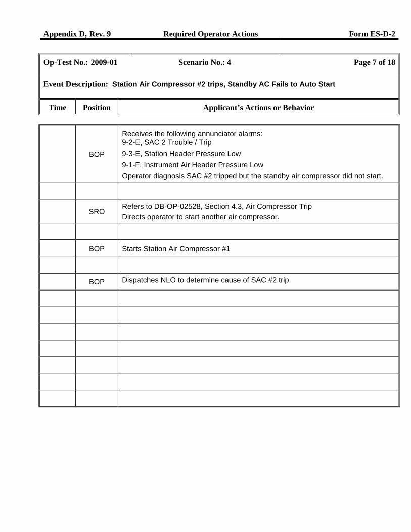
Event Description: Station Air Compressor #2 trips, Standby AC Fails to Auto Start
Time Position Applicant’s Actions or Behavior
BOP
Receives the following annunciator alarms: 9-2-E, SAC 2 Trouble / Trip 9-3-E, Station Header Pressure Low 9-1-F, Instrument Air Header Pressure Low Operator diagnosis SAC #2 tripped but the standby air compressor did not start.
SRO
Refers to DB-OP-02528, Section 4.3, Air Compressor Trip Directs operator to start another air compressor.
BOP Starts Station Air Compressor #1
BOP Dispatches NLO to determine cause of SAC #2 trip.
Appendix D, Rev. 9 Required Operator Actions Form ES-D-2
Op-Test No.: 2009-01 Scenario No.: 4 Page 8 of 18
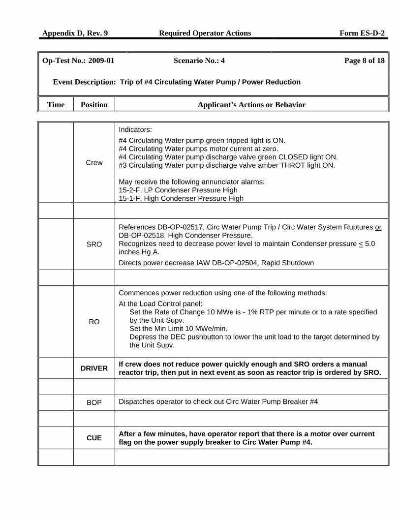
Event Description: Trip of #4 Circulating Water Pump / Power Reduction
Time Position Applicant’s Actions or Behavior
Crew
Indicators: #4 Circulating Water pump green tripped light is ON. #4 Circulating Water pumps motor current at zero. #4 Circulating Water pump discharge valve green CLOSED light ON. #3 Circulating Water pump discharge valve amber THROT light ON. May receive the following annunciator alarms: 15-2-F, LP Condenser Pressure High 15-1-F, High Condenser Pressure High
SRO
References DB-OP-02517, Circ Water Pump Trip / Circ Water System Ruptures or DB-OP-02518, High Condenser Pressure. Recognizes need to decrease power level to maintain Condenser pressure < 5.0 inches Hg A. Directs power decrease IAW DB-OP-02504, Rapid Shutdown
RO
Commences power reduction using one of the following methods: At the Load Control panel:
Set the Rate of Change 10 MWe is - 1% RTP per minute or to a rate specified by the Unit Supv. Set the Min Limit 10 MWe/min. Depress the DEC pushbutton to lower the unit load to the target determined by the Unit Supv.
DRIVER If crew does not reduce power quickly enough and SRO orders a manual
reactor trip, then put in next event as soon as reactor trip is ordered by SRO.
BOP Dispatches operator to check out Circ Water Pump Breaker #4
CUE After a few minutes, have operator report that there is a motor over current flag on the power supply breaker to Circ Water Pump #4.
Appendix D, Rev. 9 Required Operator Actions Form ES-D-2
Op-Test No.: 2009-01 Scenario No.: 4 Page 9 of 18
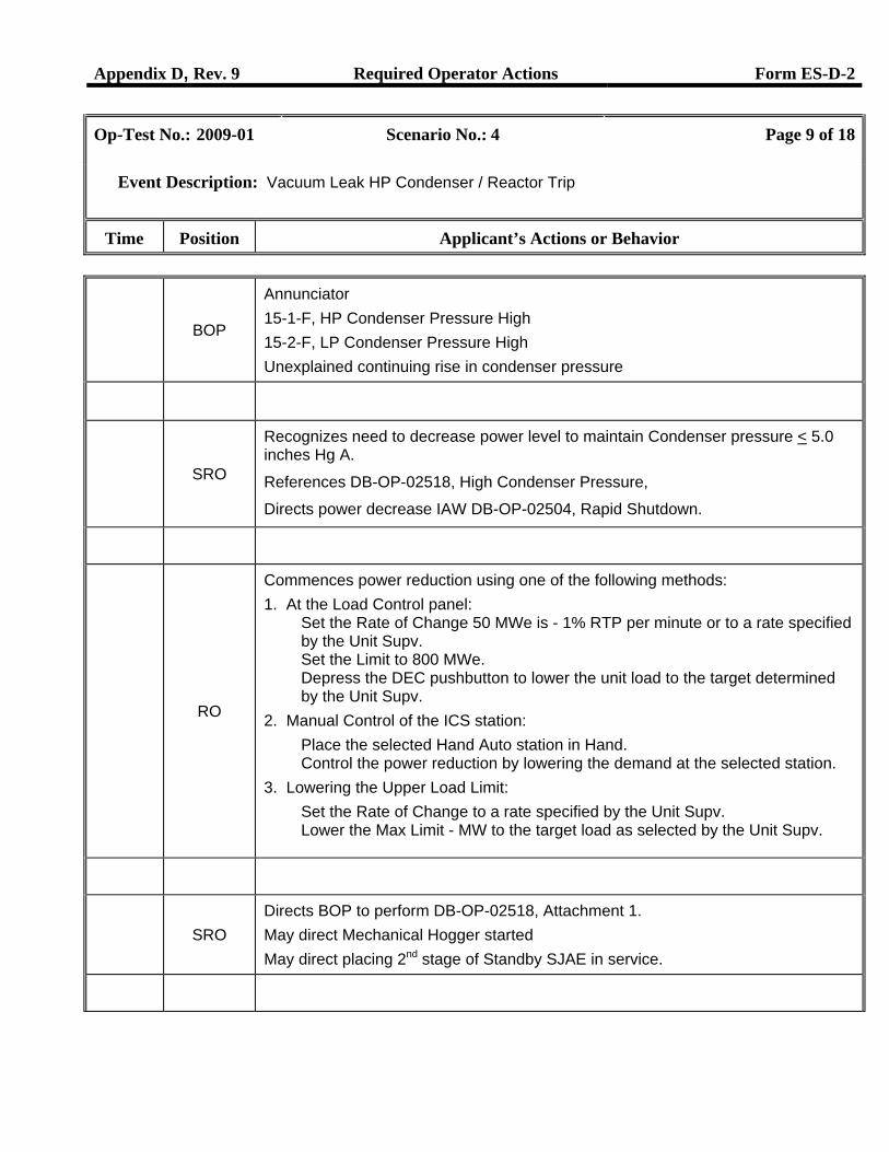
Event Description: Vacuum Leak HP Condenser / Reactor Trip
Time Position Applicant’s Actions or Behavior
BOP
Annunciator 15-1-F, HP Condenser Pressure High 15-2-F, LP Condenser Pressure High Unexplained continuing rise in condenser pressure
SRO
Recognizes need to decrease power level to maintain Condenser pressure < 5.0 inches Hg A.
References DB-OP-02518, High Condenser Pressure,
Directs power decrease IAW DB-OP-02504, Rapid Shutdown.
RO
Commences power reduction using one of the following methods: 1. At the Load Control panel:
Set the Rate of Change 50 MWe is - 1% RTP per minute or to a rate specified by the Unit Supv. Set the Limit to 800 MWe. Depress the DEC pushbutton to lower the unit load to the target determined by the Unit Supv.
2. Manual Control of the ICS station: Place the selected Hand Auto station in Hand. Control the power reduction by lowering the demand at the selected station.
3. Lowering the Upper Load Limit: Set the Rate of Change to a rate specified by the Unit Supv. Lower the Max Limit - MW to the target load as selected by the Unit Supv.
SRO
Directs BOP to perform DB-OP-02518, Attachment 1. May direct Mechanical Hogger started May direct placing 2nd stage of Standby SJAE in service.
Appendix D, Rev. 9 Required Operator Actions Form ES-D-2
Op-Test No.: 2009-01 Scenario No.: 4 Page 10 of 18
Event Description: Vacuum Leak HP Condenser / Reactor Trip / SFRCS Failure
Time Position Applicant’s Actions or Behavior
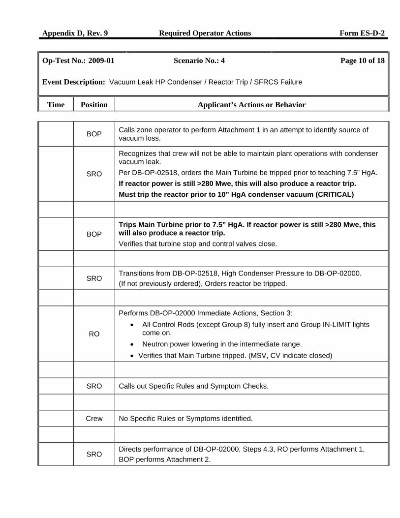
BOP Calls zone operator to perform Attachment 1 in an attempt to identify source of
vacuum loss.
SRO
Recognizes that crew will not be able to maintain plant operations with condenser vacuum leak. Per DB-OP-02518, orders the Main Turbine be tripped prior to teaching 7.5” HgA. If reactor power is still >280 Mwe, this will also produce a reactor trip. Must trip the reactor prior to 10” HgA condenser vacuum (CRITICAL)
BOP
Trips Main Turbine prior to 7.5” HgA. If reactor power is still >280 Mwe, this will also produce a reactor trip. Verifies that turbine stop and control valves close.
SRO Transitions from DB-OP-02518, High Condenser Pressure to DB-OP-02000. (If not previously ordered), Orders reactor be tripped.
RO
Performs DB-OP-02000 Immediate Actions, Section 3: • All Control Rods (except Group 8) fully insert and Group IN-LIMIT lights
come on. • Neutron power lowering in the intermediate range. • Verifies that Main Turbine tripped. (MSV, CV indicate closed)
SRO Calls out Specific Rules and Symptom Checks.
Crew No Specific Rules or Symptoms identified.
SRO Directs performance of DB-OP-02000, Steps 4.3, RO performs Attachment 1, BOP performs Attachment 2.
Appendix D, Rev. 9 Required Operator Actions Form ES-D-2
Op-Test No.: 2009-01 Scenario No.: 4 Page 11 of 18
Event Description: Vacuum Leak HP Condenser / Reactor Trip / SFRCS Failure
Time Position Applicant’s Actions or Behavior
RO
Performs DB-OP-02000, Attachment 1: • Lock MU3971 and MU6405 in the BWST position • Verifies second makeup Pump is running • Set Pressurizer Level Controller to 100 inches. • Control Makeup System per Attachment 13.
BOP
Performs DB-OP-02000, Attachment 2:
Verify Steam Generator Pressures are being controlled by automatic operation of the Turbine Bypass Valves (TBVs) or Atmospheric Vent Valves (AVVs). When Condensate Flow is less than 3.5 MPPH, then establish one Condensate Pump operation. (Actions for this are found on pg 17)
BOP Acknowledges that with both MFPs tripped, SFRCS did not automatically
actuate.
SRO
SRO directs manual Initiation and Isolation of SFRCS equipment using DB-OP-02000, Table 1, SFRCS Actuated Equipment.
BOP
Manually repositions SFRCS equipment IAW DB-OP-02000, Table 1. (Table 1 is attached, see pages 15 and 16. BOP performs last column in Table, Manual Initiate & Isolate. Must isolate since condenser is not available!)
SRO
Directs steps from DB-OP-02000, Section 4:
4.5 Check for NNI Power available. 4.6 Check for ICS Power available. 4.7 Check for Instrument Air available. 4.8 Check SFAS has NOT actuated AND plant conditions do NOT require an SFAS actuation.
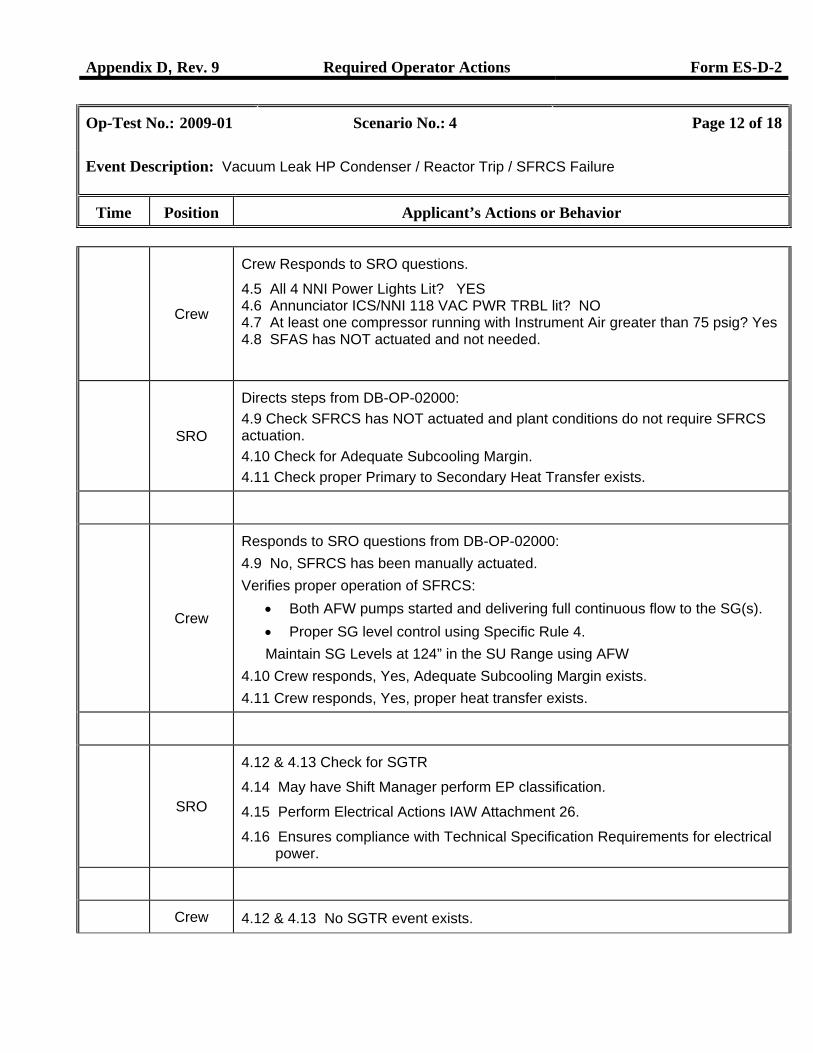
Appendix D, Rev. 9 Required Operator Actions Form ES-D-2
Op-Test No.: 2009-01 Scenario No.: 4 Page 12 of 18
Event Description: Vacuum Leak HP Condenser / Reactor Trip / SFRCS Failure
Time Position Applicant’s Actions or Behavior
Crew
Crew Responds to SRO questions.
4.5 All 4 NNI Power Lights Lit? YES 4.6 Annunciator ICS/NNI 118 VAC PWR TRBL lit? NO 4.7 At least one compressor running with Instrument Air greater than 75 psig? Yes 4.8 SFAS has NOT actuated and not needed.
SRO
Directs steps from DB-OP-02000: 4.9 Check SFRCS has NOT actuated and plant conditions do not require SFRCS actuation. 4.10 Check for Adequate Subcooling Margin. 4.11 Check proper Primary to Secondary Heat Transfer exists.
Crew
Responds to SRO questions from DB-OP-02000: 4.9 No, SFRCS has been manually actuated. Verifies proper operation of SFRCS:
• Both AFW pumps started and delivering full continuous flow to the SG(s). • Proper SG level control using Specific Rule 4. Maintain SG Levels at 124” in the SU Range using AFW
4.10 Crew responds, Yes, Adequate Subcooling Margin exists. 4.11 Crew responds, Yes, proper heat transfer exists.
SRO
4.12 & 4.13 Check for SGTR
4.14 May have Shift Manager perform EP classification.
4.15 Perform Electrical Actions IAW Attachment 26.
4.16 Ensures compliance with Technical Specification Requirements for electrical power.
Crew 4.12 & 4.13 No SGTR event exists.
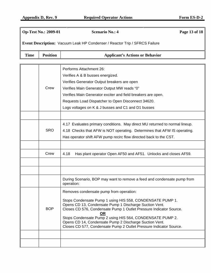
Appendix D, Rev. 9 Required Operator Actions Form ES-D-2
Op-Test No.: 2009-01 Scenario No.: 4 Page 13 of 18
Event Description: Vacuum Leak HP Condenser / Reactor Trip / SFRCS Failure
Time Position Applicant’s Actions or Behavior
Crew
Performs Attachment 26:
Verifies A & B busses energized.
Verifies Generator Output breakers are open
Verifies Main Generator Output MW reads “0”
Verifies Main Generator exciter and field breakers are open.
Requests Load Dispatcher to Open Disconnect 34620.
Logs voltages on K & J busses and C1 and D1 busses
SRO
4.17 Evaluates primary conditions. May direct MU returned to normal lineup.
4.18 Checks that AFW is NOT operating. Determines that AFW IS operating.
Has operator shift AFW pump recirc flow directed back to the CST.
Crew 4.18 Has plant operator Open AF50 and AF51. Unlocks and closes AF59.
During Scenario, BOP may want to remove a feed and condensate pump from operation:
BOP
Removes condensate pump from operation: Stops Condensate Pump 1 using HIS 558, CONDENSATE PUMP 1. Opens CD 13, Condensate Pump 1 Discharge Suction Vent. Closes CD 576, Condensate Pump 1 Outlet Pressure Indicator Source.
OR Stops Condensate Pump 2 using HIS 564, CONDENSATE PUMP 2. Opens CD 14, Condensate Pump 2 Discharge Suction Vent. Closes CD 577, Condensate Pump 2 Outlet Pressure Indicator Source.
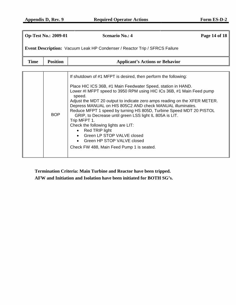
Appendix D, Rev. 9 Required Operator Actions Form ES-D-2
Op-Test No.: 2009-01 Scenario No.: 4 Page 14 of 18
Event Description: Vacuum Leak HP Condenser / Reactor Trip / SFRCS Failure
Time Position Applicant’s Actions or Behavior
BOP
If shutdown of #1 MFPT is desired, then perform the following: Place HIC ICS 36B, #1 Main Feedwater Speed, station in HAND. Lower #I MFPT speed to 3950 RPM using HIC ICs 36B, #1 Main Feed pump speed. Adjust the MDT 20 output to indicate zero amps reading on the XFER METER. Depress MANUAL on HIS 805C2 AND check MANUAL illuminates. Reduce MFPT 1 speed by turning HS 805D, Turbine Speed MDT 20 PISTOL GRIP, to Decrease until green LSS light IL 805A is LIT. Trip MFPT 1. Check the following lights are LIT:
• Red TRIP light • Green LP STOP VALVE closed • Green HP STOP VALVE closed
Check FW 488, Main Feed Pump 1 is seated.
Termination Criteria: Main Turbine and Reactor have been tripped. AFW and Initiation and Isolation have been initiated for BOTH SG’s.
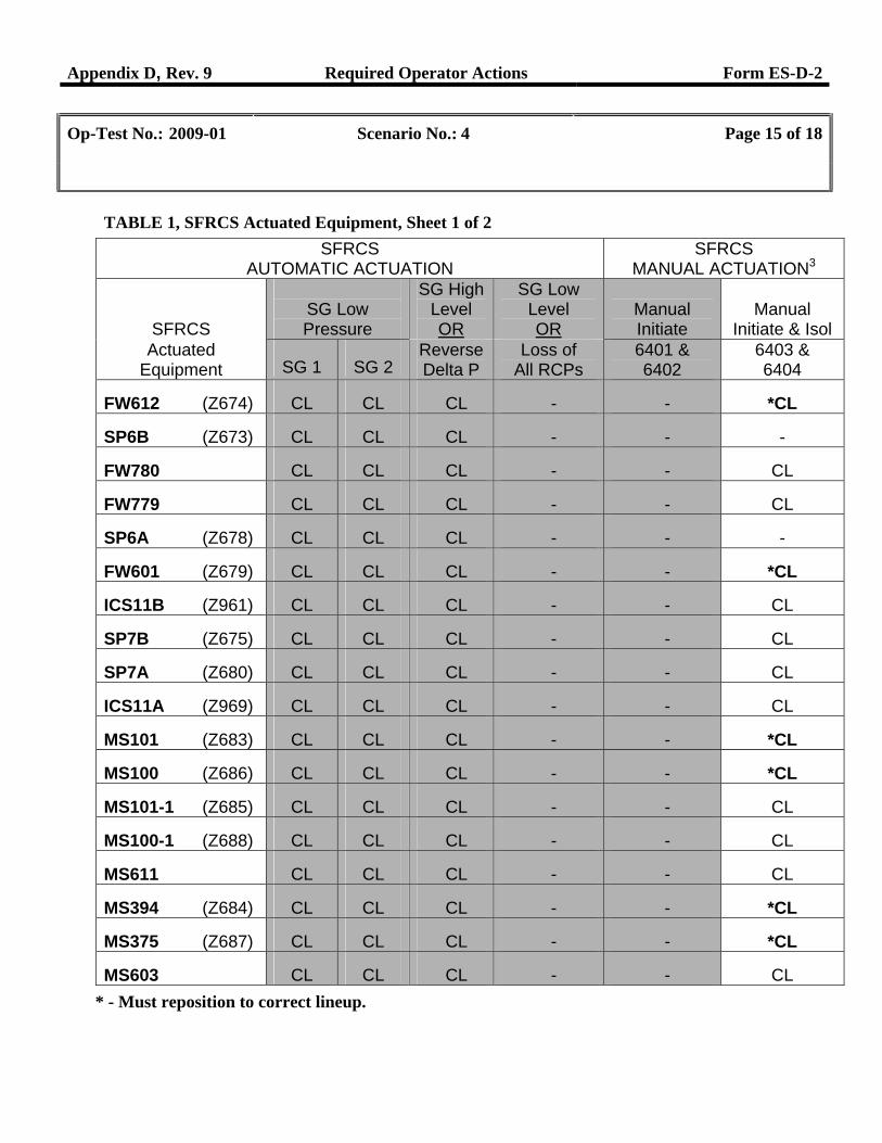
Appendix D, Rev. 9 Required Operator Actions Form ES-D-2
Op-Test No.: 2009-01 Scenario No.: 4 Page 15 of 18
TABLE 1, SFRCS Actuated Equipment, Sheet 1 of 2
SFRCS AUTOMATIC ACTUATION
SFRCS MANUAL ACTUATION3
SFRCS
SG Low Pressure
SG High Level OR
SG Low Level OR
Manual Initiate
Manual
Initiate & Isol Actuated
Equipment SG 1 SG 2 Reverse Delta P
Loss of All RCPs
6401 & 6402
6403 & 6404
FW612 (Z674) CL CL CL - - *CL
SP6B (Z673) CL CL CL - - -
FW780 CL CL CL - - CL
FW779 CL CL CL - - CL
SP6A (Z678) CL CL CL - - -
FW601 (Z679) CL CL CL - - *CL
ICS11B (Z961) CL CL CL - - CL
SP7B (Z675) CL CL CL - - CL
SP7A (Z680) CL CL CL - - CL
ICS11A (Z969) CL CL CL - - CL
MS101 (Z683) CL CL CL - - *CL
MS100 (Z686) CL CL CL - - *CL
MS101-1 (Z685) CL CL CL - - CL
MS100-1 (Z688) CL CL CL - - CL
MS611 CL CL CL - - CL
MS394 (Z684) CL CL CL - - *CL
MS375 (Z687) CL CL CL - - *CL
MS603 CL CL CL - - CL * - Must reposition to correct lineup.
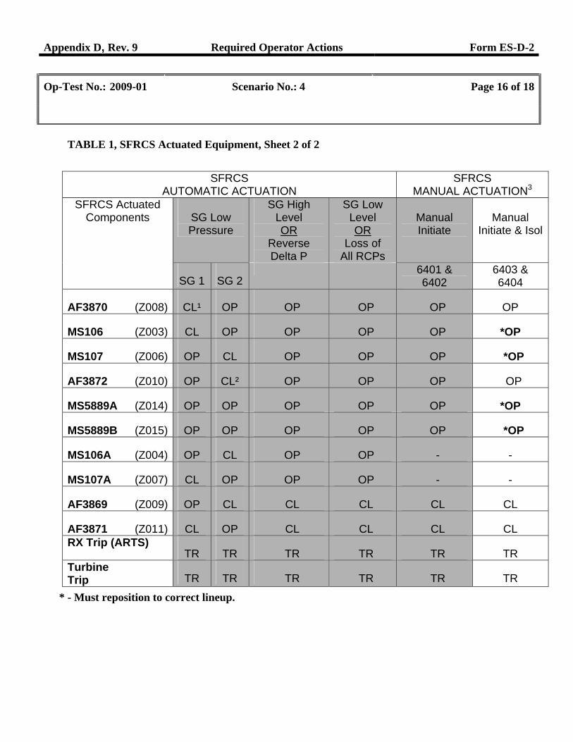
Appendix D, Rev. 9 Required Operator Actions Form ES-D-2
Op-Test No.: 2009-01 Scenario No.: 4 Page 16 of 18
TABLE 1, SFRCS Actuated Equipment, Sheet 2 of 2
SFRCS
AUTOMATIC ACTUATION SFRCS
MANUAL ACTUATION3 SFRCS Actuated
Components
SG Low Pressure
SG High Level OR
Reverse Delta P
SG Low Level OR
Loss of All RCPs
Manual Initiate
Manual
Initiate & Isol
SG 1 SG 2
6401 & 6402
6403 & 6404
AF3870 (Z008) CL¹ OP OP OP OP OP
MS106 (Z003) CL OP OP OP OP *OP
MS107 (Z006) OP CL OP OP OP *OP
AF3872 (Z010) OP CL² OP OP OP OP
MS5889A (Z014) OP OP OP OP OP *OP
MS5889B (Z015) OP OP OP OP OP *OP
MS106A (Z004) OP CL OP OP - -
MS107A (Z007) CL OP OP OP - -
AF3869 (Z009) OP CL CL CL CL CL
AF3871 (Z011) CL OP CL CL CL CL RX Trip (ARTS)
TR TR TR TR TR TR Turbine Trip TR TR TR TR TR TR
* - Must reposition to correct lineup.
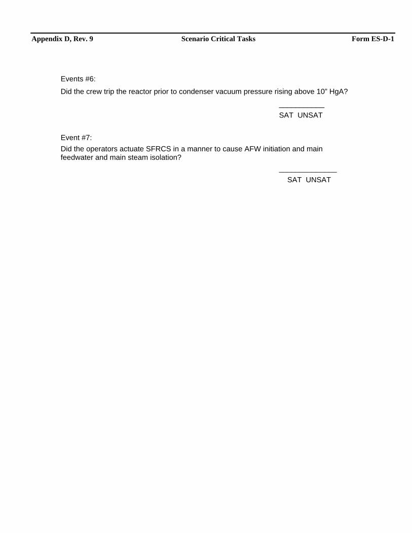
Appendix D, Rev. 9 Scenario Critical Tasks Form ES-D-1
Events #6:
Did the crew trip the reactor prior to condenser vacuum pressure rising above 10” HgA?
___________ SAT UNSAT Event #7: Did the operators actuate SFRCS in a manner to cause AFW initiation and main feedwater and main steam isolation? ______________ SAT UNSAT
Appendix D, Rev. 9 Form ES-D-1
TURNOVER Initial Conditions: Unit is at 95% power. Turnover: Swap Letdown Purification Demineralizers IAW DB-OP-06006, Section 3.14: