Embed Size (px)
Citation preview

This represents a sinusoidal wave of frequency . This is amplitude modulated by a very slowly varying sinusoidal of frequency . This system of waves, i.e. the modulation, travels along z at a speed determined by the modulating term, cos[()t(k)z]. The maximum in the field occurs when [()t(k)z] = 2m = constant (m is an integer), which travels with a velocity
dz
dtk
or
dk
dgv
This is the group velocity of the waves because it determines the speed of propagation of the maximum electric field along z.
Ex(z,t) = 2Eocos[()t(k)z][cos(tkz)]

The group velocity therefore defines the speed with which energy or information is propagated.
w = 2pc/lo and k = 2pn/lo, lo is the free space wavelength.
Differentiate the above equations in red
dw = -(2pc/lo2)dlo
oo
ooo dd
dndndk
)/2()/1(2 2
vg
ddk
oo
oo dd
dnndk
)/2( 2
ooo
ooo
oo
d
dnn
c
dd
dnn
dc
dk
d
)/2(
)/2(
2
2
gv

where n = n() is a function of the wavelength. The group velocity vg in a medium is given by,
vg(medium) ddk
c
n dn
d
This can be written as
vg(medium)
c
Ng
Group Velocity and Group Index

Ng n
dn
d
is defined as the group index of the medium
In general, for many materials the refractive index n and hence the group index Ng depend on the wavelength of light. Such materials are called dispersive
Group Index

Refractive index n and the group index Ng of pure SiO2 (silica) glass as a function of wavelength.
Refractive Index and Group Index

Magnetic Field, Irradiance and Poynting Vector
The magnetic field (magnetic induction) component By always accompanies Ex in an EM wave propagation.
If v is the phase velocity of an EM wave in an isotropic dielectric medium and n is the refractive index, then
yyx Bn
cBE v
where v = (oro)1/2 and n = 1/2

A plane EM wave traveling along k crosses an area A at right angles to the direction ofpropagation. In time t, the energy in the cylindrical volume At (shown dashed) flowsthrough A.
EM wave carries energy along the direction of propagation k.What is the radiation power flow per unit area?

As the EM wave propagates in the direction of the wavevector k, there is an energy flow in this direction. The wave brings with it electromagnetic energy.
The energy densities in the Ex and By fields are the same,
22
2
1
2
1y
oxro BE
The total energy density in the wave is therefore orEx2.
Energy Density in an EM Wave

If S is the EM power flow per unit area,
S = Energy flow per unit time per unit area
yxroxroxro BEE
tA
EtAS 22
2 ))((vv
v
In an isotropic medium, the energy flow is in the direction of wave propagation. If we use the vectors E and B to represent the electric and magnetic fields in the EM wave, then the EM power flow per unit area can be written as
Poynting Vector and EM Power Flow
S = v2orEB

where S, called the Poynting vector, represents the energy flow per unit time per unit area in a direction determined by EB (direction of propagation). Its magnitude, power flow per unit area, is called the irradiance (instantaneous irradiance, or intensity).
The average irradiance is
221
average oro ESI v
Poynting Vector and Intensity

Since v = c/n and r = n2 we can write
23221
average )1033.1( ooo nEnEcSI
The instantaneous irradiance can only be measured if the power meter can respond more quickly than the oscillations of the electric field. Since this is in the
optical frequencies range, all practical measurements yield the average irradiance because all detectors have a response rate much slower than the
frequency of the wave.
Average Irradiance or Intensity

Irradiance of a Spherical Wave
24 r
PI o
Perfect spherical wave

Spherical wave front
9A4AAA
r
2r
3r
OSource
Po
Irradiance of a Spherical Wave
24 r
PI o

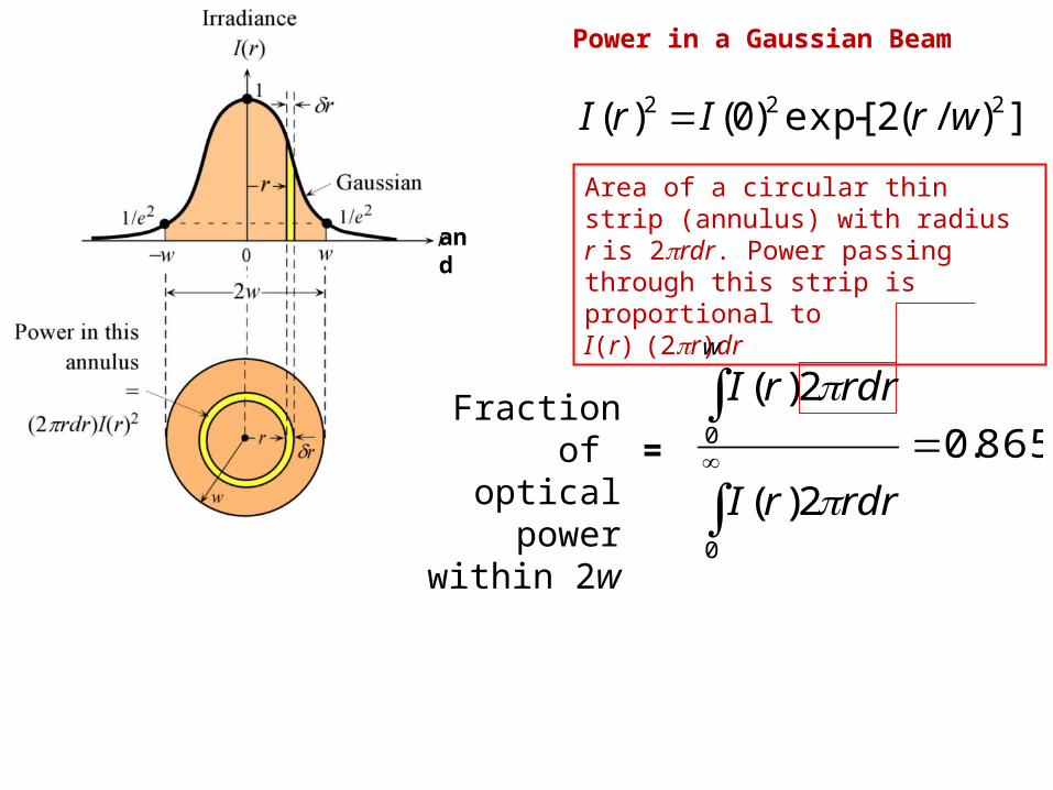
A Gaussian Beam
I(r, z) = Imaxexp(-2r2/w2)

A Gaussian Beam
I(r,z) = [2Po/(pw2)]exp(-2r2/w2)
q = w/z = l/(pwo) 2q = Far field divergence
Imax
A Gaussian Beam
I(r,z) = Imaxexp(-2r2/w2)
221max w
PI o
2
2
2
2 2exp),(
w
r
w
wIrzI o
o
oo z
zww 22
Beyond the Rayleigh range
z > zo
2
2
2
2
max)0,(z
zI
w
wIIzI o
oo
o
Io = Maximum irradiance at the center r = 0 at the waist
Corrected
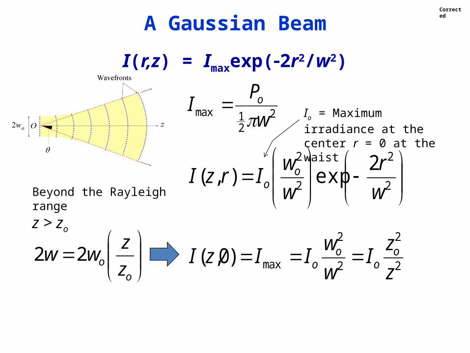
Power in a Gaussian Beam
])/(2exp[)0()( 222 wrIrI
865.0
2)(
2)(
0
0
rdrrI
rdrrIw
Fraction of optical power
within 2w=
Area of a circular thin strip (annulus) with radius r is 2prdr. Power passing through this strip is proportional to I(r) (2pr)dr
and

221
o
oo w
PI
Io = Maximum irradiance at the center r = 0 at the waist
Example on
Gaussian Beam
Example 1.4.2 Power and irradiance of a Gaussian beamConsider a 5 mW HeNe laser that is operating at 633 nm, and has a spot size that is 1 mm. Find the maximum irradiance of the beam and the axial (maximum) irradiance at 25 m from the laser.
SolutionThe 5 mW rating refers to the total optical power Po available, and 633 nm is the free space output wavelength l. Apply
)( 221
ooo wIP
]m)105.0([W105 23213 oI
Io = 1.273 W cm-2
Corrected

Example on 2
2
2
2
max)0,(z
zI
w
wIIzI o
oo
o
Gaussian Beam
The Rayleigh range zo was calculated previously, but we can recalculate
zo = pwo2/l = p(0.510-3 m)2/(63310-9 m) = 1.24 m.
The beam width at 25 m is
2w = 2wo[1 + (z/zo)]1/2 = 20 mm
The irradiance at the beam axis is
22
22
2
2
axis cmmW14.3)m25(
)m24.1()cmW273.1(
z
zII o
o

Snell’s Law or Descartes’s Law?

Snell's Law
1
2
sin
sin
n
n
t
i

A light wave traveling in a medium with a greater refractive index (n1 > n2) suffers reflection and refraction at the boundary. (Notice that lt is slightly longer than .l )
Derivation of Snell’s Law

We can use constructive interference to show that there can only be one reflected wave which occurs at an angle equal to the incidence angle. The two waves along Ai and Bi are in phase.
When these waves are reflected to become waves Ar and Br then they must still be in phase, otherwise they will interfere destructively and destroy each other. The only way the two waves can stay in phase is if r = i. All other angles lead to the waves Ar and Br being out of phase and interfering destructively.
Snell’s Law

Unless the two waves at A and B still have the same phase, there will be no transmitted wave. A and B points on the front are only in phase for one particular transmitted angle, t.
It takes time t for the phase at B on wave Bi to reach BBB = v1t = ct/n1
During this time t, the phase A has progressed to AAA = v2t = ct/n2
A and B belong to the same front just like A and B so that AB is perpendicular to ki in medium 1 and AB is perpendicular to kt in medium 2. From geometrical considerations,
AB = BB/sini and AB = AA/sint so that
Snell’s Law

or A B
v1t
sin i
v2t
sin t
sini
sint
v1
v2
n2
n1
This is Snell's law which relates the angles of incidence and refraction to the refractive indices of the media.
ti nn sinsin 21
constantsin n

When n1 > n2 then obviously the transmitted angle is greater than the incidence angle as apparent in the figure. When the refraction angle t reaches 90°, the
incidence angle is called the critical angle c which is given by
ti nn sinsin 21
1
2sinn
nc

When the incidence angle i exceeds c then there is no transmitted wave but only a reflected wave. The latter phenomenon is called total internal reflection (TIR). TIR phenomenon that leads to the propagation of waves in a dielectric medium surrounded by a medium of smaller refractive index as in optical waveguides, e.g. optical fibers.
Although Snell's law for i > c shows that sint > 1 and hence t is an "imaginary" angle of refraction, there is however an attenuated wave called the evanescent wave.
1
2sinn
nc
Snell’s Law

Light wave traveling in a more dense medium strikes a less dense medium. Depending on the incidence angle with respect to qc, which is determined by the
ratio of the refractive indices, the wave may be transmitted (refracted) or reflected.
(a) qi < qc (b) qi = qc (c) qi > qc and total internal reflection (TIR).
Total Internal Reflection

Prisms

io
ii
nnL
d
22 sin)/(
cos1sin
Lateral Displacement

Example: Lateral DisplacementLateral displacement of light, or, beam displacement, occurs when a beam if light passes obliquely through a plate of transparent material, such as a glass plate. When a light beam is incident on a plate of transparent material of refractive index n, it emerges from the other side traveling parallel to the incident light but displaced from it by a distance d, called lateral displacement. Find the displacement d in terms of the incidence angle the plate thickness L. What is d for a glass of n = 1.600, L = 10 mm if the incidence angle is 45
Solution
The displacement d = BC = ABsin(qi - qt). Further, L/AB = cosqt so that combining these two equation we find
t
tiLd
cos
)sin(

Example: Lateral Displacement (Continued)
Solution (Continued)
t
tiLd
cos
)sin(
tt 2sin1cos
Snell's law nsinqt = nosinqi
tititi sincoscossin)sin(
io
ii
nnL
d
22 sin)/(
cos1sin
Expand sin(qi - qt) and eliminate sinqt and sinqt

Example: Lateral Displacement (Continued)
Solution (Continued)
io
ii
nnL
d
22 sin)/(
cos1sin
L = 10 mm
qi = 45
n = 1.600 no = 1
d = 3.587 mm

Light travels by total internal reflection in optical fibers
An optical fiber link for transmitting digital information in communications. The fiber corehas a higher refractive index so that the light travels along the fiber inside the fiber coreby total internal reflection at the core-cladding interface.

A small hole is made in a plastic bottle full of water to generate a water jet. When the hole is illuminated with a laser beam (from a green laser pointer), the light is guided by total internal reflections along the jet to the tray. The light guiding by a water jet was first demonstrated by Jean-Daniel Colladan, a Swiss scientist (Water with air bubbles was used to increase the visibility of light. Air bubbles scatter light.) [Left: Copyright: S.O. Kasap, 2005] [Right: Comptes Rendes, 15, 800–802, October 24, 1842; Cnum, Conservatoire Numérique des Arts et Métiers, France


Fresnel's Equations
Light wave traveling in a more dense medium strikes a less dense medium. The plane of incidence is the plane of the paper and is perpendicular to the flat interface between the two media. The electric field is normal to the direction of
propagation. It can be resolved into perpendicular and parallel components.

Describe the incident, reflected and refracted waves by the exponential representation of a traveling plane wave, i.e.
Ei = Eioexpj(tkir) Incident wave
Er = Eroexpj(tkrr) Reflected wave
Et = Etoexpj(tktr) Transmitted wave
Fresnel's Equations
These are traveling plane waves

where r is the position vector, the wave vectors ki, kr and kt describe the directions of the incident, reflected and transmitted waves and Eio, Ero and Eto are the respective amplitudes.
Any phase changes such as r and t in the reflected and transmitted waves with respect to the phase of the incident wave are incorporated into the complex amplitudes, Ero and Eto. Our objective is to find Ero and
Eto with respect to Eio.
Fresnel's Equations

The electric and magnetic fields anywhere on the wave must be perpendicular to each other as a requirement of electromagnetic wave theory. This means that with E// in the EM wave we have a magnetic field B associated with it such that, B(n/c)E//. Similarly E will have a magnetic field B// associated with it such that B//(n/c)E.
We use boundary conditions
Etangential(1) = Etangential(2)
Fresnel's Equations

Mon-magnetic media (relative permeability, r = 1),
Btangential(1) = Btangential(2)
Using the above boundary conditions for the fields at y = 0, and the relationship between the electric and magnetic fields, we can find the reflected and transmitted waves in terms of the incident wave.
The boundary conditions can only be satisfied if the reflection and incidence angles are equal, r = i and the angles for the transmitted and incident wave obey Snell's law, n1sin1 = n2sin2
Fresnel's Equations

Fresnel's Equations
Incident wave Ei = Eioexpj(tkir)
Reflected wave Er = Eroexpj(tkrr)
Transmitted wave Et = Etoexpj(tktr)

Applying the boundary conditions to the EM wave going from medium 1 to 2, the amplitudes of the reflected and transmitted waves can be readily obtained in terms of n1, n2 and the incidence angle i alone. These relationships are called Fresnel's equations. If we define n = n2/n1, as the relative refractive index of medium 2 to that of 1, then the reflection and transmission coefficients for Eare,
2/122
2/122
,0
,0
sincos
sincos
ii
ii
i
r
n
n
E
E
r
Fresnel's Equations

2/122,0
,0
sincos
cos2
ii
i
i
t
nE
E
t
There are corresponding coefficients for the E// fields with corresponding reflection and transmission coefficients, r// and t//,
ii
ii
i
r
nn
nn
E
E
cossin
cossin22/122
22/122
//,0
//,0//
r
2/1222//,0
//,0//
sincos
cos2
ii
i
i
t
nn
n
E
E
t
Fresnel's Equations

Further, the above coefficients are related by
r// + nt// = 1 and r + 1 = t
For convenience we take Eio to be a real number so that phase angles of r and t correspond to the phase changes measured with respect to the incident wave.
For normal incidence (i = 0) into Fresnel's equations we find,
21
21// nn
nn
rr
Fresnel's Equations

Internal reflection
(a) Magnitude of the reflection coefficients r// and r vs. angle of incidence i for n1 = 1.44 andn2 = 1.00. The critical angle is 44.
(b) The corresponding changes // and vs. incidence angle.

We find a special incidence angle, labeled as p, by solving the Fresnel equation for r// = 0. The field in the reflected wave is then always perpendicular to the plane of incidence and hence well-defined. This special angle is called the polarization angle or Brewster's angle,
1
2tann
np
Reflection and Polarization Angle
0
cossin
cossin22/122
22/122
//,0
//,0//
ii
ii
i
r
nn
nn
E
E
r
For both n1 > n2 or n1 < n2.

Polarized Light
A linearly polarized wave has its electric field oscillations defined along a line perpendicular to the direction of propagation, z. The field vector E and z define a plane of polarization.
x
y
z
E
Plane of polarization

Brewster's angle
Reflected light at qi = qp has only E^
for both n1 > n2 or n1 < n2.
E^

In linearly polarized light, however, the field oscillations are contained within a well defined plane. Light emitted from many light sources such as a tungsten light bulb or an LED diode is unpolarized and the field is randomly oriented in a direction that is perpendicular to the direction of propagation.
At the critical angle and beyond (past 44° in the figure), i.e. when i c, the magnitudes of both r// and rgo to unity so that the reflected wave has the same amplitude as the incident wave. The incident wave has suffered total internal reflection, TIR.
Total Internal Reflection
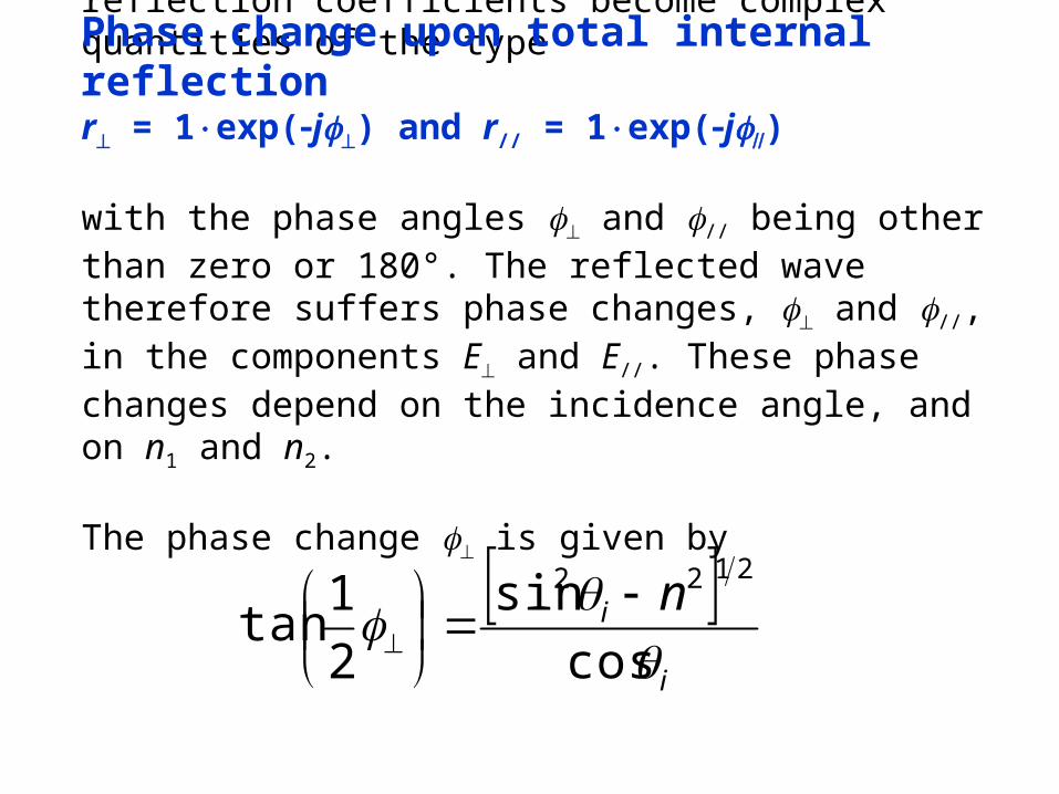
When i > c, in the presence of TIR, the reflection coefficients become complex quantities of the type
r = 1exp(j) and r// = 1exp(j) with the phase angles and // being other than zero or 180°. The reflected wave therefore suffers phase changes, and //, in the components E and E//. These phase changes depend on the incidence angle, and on n1 and n2.
The phase change is given by
i
i n
cos
sin
2
1tan
2122
Phase change upon total internal reflection