Embed Size (px)
Citation preview


This owner’s manual applies to the KIZASHI series:
57L1F001
NOTE: The illustrated model is one of the KIZASHI series.
© 2009 All rights reserved.No part of this document may be reproduced or transmitted in any form or by any means, electronic ormechanical, for any purpose, without the express written permission of Suzuki Motor Corporation.
Prepared by
December, 2010
Part No. 99011-57L20-03EPrinted in U.S.A.
TP384

57L20-03E
FOREWORD
All information in this manual is basedon the latest product information avail-able at the time of publication. Due toimprovements or other changes, theremay be discrepancies between informa-tion in this manual and your vehicle. SUZUKI MOTOR CORPORATIONreserves the right to make productionchanges at any time, without notice andwithout incurring any obligation tomake the same or similar changes tovehicles previously built or sold.
SUZUKI MOTOR CORPORATIONbelieves in conservation and protection ofEarth’s natural resources.
To that end, we encourage every vehicleowner to recycle, trade in, or properly dis-pose of, as appropriate, used motor oil,coolant, and other fluids, batteries andtires.
IF YOU HAVE ANY PROBLEMS WITHYOUR SUZUKI:
Please review the New Vehicle WarrantyInformation booklet supplied with yourSUZUKI. Should you have a question orproblem regarding the warranty or serviceof your vehicle, please take the followingaction:
Consult the Service Manager and theOwner of the Suzuki Automotive Dealer-ship. Explain your problem and ask fortheir assistance in resolving your problem.The Owner of the dealership is in the verybest position to assist you as he or she isvitally concerned with your continued satis-faction.
If, after doing so, you still require furtherassistance, and you purchased yourSUZUKI in the continental United States,please contact the American Suzuki Cus-tomer Relations Department by telephoneat 1-800-934-0934 or in writing at:
American Suzuki Motor CorporationAutomotive Customer Relations3251 East Imperial HighwayBrea, CA 92821-6795
If you purchased your SUZUKI in Canadaplease contact the Suzuki Canada Cus-tomer Relations Department by telephoneat 1-905-889-2677 extension 2254 or inwriting at:
Suzuki Canada Inc.Customer Relations100 East Beaver Creek RoadRichmond Hill, OnL4B 1J6
In the event you require assistance relatedto your SUZUKI, while temporarily travel-ling in either the United States or Canada,you may wish to contact the Suzuki Cus-tomer Relations Department directly of thecountry in which you are temporarily oper-ating your vehicle.
Please be certain to provide us with the fol-lowing information: the model, VehicleIdentification Number, mileage, accesso-ries involved, event dates, your concern,and any other comments which you mayhave. When we receive your correspon-dence, we will be pleased to contact theOwner of your dealership and assist inresolving your concern.
For owners outside the continental UnitedStates, please refer to the distributor’saddress listed in your Warranty Informationbooklet.

57L20-03E
IMPORTANTWARNING/CAUTION/NOTE
Please read this manual and follow itsinstructions carefully. To emphasize spe-cial information, the symbol and thewords WARNING, CAUTION and NOTEhave special meanings. Pay special atten-tion to the messages highlighted by thesesignal words:
NOTE:Indicates special information to makemaintenance easier or instructions clearer.
75F135
The circle with a slash in this manualmeans “Don’t do this” or “Don’t let this hap-pen”.
MODIFICATION WARNING
WARNINGIndicates a potential hazard thatcould result in death or injury.
CAUTIONIndicates a potential hazard thatcould result in vehicle damage.
WARNINGDo not modify this vehicle. Modifica-tion could adversely affect safety,handling, performance or durabilityand may violate governmental regula-tions. In addition, damage or perfor-mance problems resulting frommodification may not be coveredunder warranty.
CAUTIONImproper installation of mobile com-munication equipment such as cellu-lar telephones or CB (Citizen’s Band)radios may cause electronic interfer-ence with your vehicle’s ignition sys-tem, resulting in vehicle performanceproblems. Consult your SUZUKIdealer or qualified service technicianfor advice on installing such mobilecommunication equipment.

57L20-03E
LEAK DETECTION PUMPNOTE:Your vehicle has a pump to regularly checkthe vehicle’s evaporative emission controlsystem for leaks. This check is performedapproximately five hours after the engine isturned off. During this leak check, you mayhear a sound coming from the vehicle forseveral minutes. This sound is normal anddoes not indicate a malfunction.

57L20-03E
MEMO

57L20-03E
INTRODUCTIONThank you for choosing SUZUKI and welcome to our growing family. Your choice was a wise one; SUZUKI products are a great valuethat will give you years of driving pleasure.
This Owner’s Manual was prepared to help you have a safe, enjoyable, and trouble-free experience with your SUZUKI. In it you will learnabout the vehicle’s operation, its safety features and maintenance requirements. Please read it carefully before operating your vehicle.Afterwards, keep this Manual in the glove box for future reference.
Should you resell the vehicle, please leave this Manual with it for the next owner.
In addition to the Owner’s Manual, the other booklets provided with your SUZUKI explain the vehicle’s warranties. We recommend youread them as well to familiarize yourself with this important information.
When planning the regular scheduled maintenance of your SUZUKI, we recommend you visit your local SUZUKI dealership. Their fac-tory-trained technicians will provide the best possible service and use only genuine SUZUKI parts and accessories.

57L20-03E
SERVICE STATION GUIDE1. Fuel (see section 1)2. Engine hood (see section 5)3. Tire changing tools (see section 8)4. Engine oil dipstick <Yellow>
(see section 7)5. CVT fluid dipstick <Red or Orange>
(see section 7)6. Engine coolant (see section 7)7. Windshield washer fluid
(see section 7)8. Battery (see section 7)9. Tire pressure (see Tire Information
Label on driver’s door lock pillar)10. Spare tire (see section 7)
57L1F002
2
2
7
19
3
10
8
4
6
5

57L20-03E
TABLE OF CONTENTS
California Proposition 65 Warning
WARNINGEngine exhaust, some of its constitu-ents, and certain product compo-nents contain or emit chemicalsknown to the State of California tocause cancer and birth defects orother reproductive harm.
FUEL RECOMMENDATION 1
BEFORE DRIVING 2
OPERATING YOUR VEHICLE 3
DRIVING TIPS 4
OTHER CONTROLS AND EQUIPMENT 5
VEHICLE LOADING AND TOWING 6
INSPECTION AND MAINTENANCE 7
EMERGENCY SERVICE 8
APPEARANCE CARE 9
GENERAL INFORMATION 10
FUSES AND PROTECTED CIRCUITS 11
SPECIFICATIONS 12
INDEX 13

ILLUSTRATED TABLE OF CONTENTS
57L20-03E
EXTERIOR1. High-mount Stop Light (P.12-3)2. Rear Combination Light (P.7-53)3. Radio Antenna (P.5-9)4. Engine Hood (P.5-75)5. Headlight (P.2-100, P.7-46)6. Windshield Wiper (P.2-107)7. Outside Rearview Mirror (P.2-22)8. Fuel Filler Cap (P.5-74)9. License Plate Light (P.7-53)
10. Trunk Lid (P.2-5)11. Front Fog Light (if equipped)
(P.2-105, P.7-50)12. Side Marker Light (P.7-51)13. Side Turn Signal Light (P.7-50)14. Door Locks (P.2-3)
57L1F003
1 5 72 3 4 6 8
109 11 14 1312

ILLUSTRATED TABLE OF CONTENTS
57L20-03E
INTERIOR1. Seat Belts (P.2-34)2. Side Curtain Air Bags (P.2-59)3. Assist Grip (P.5-82)4. Interior Light (P.5-78, P.7-45)5. Sun Visor (P.5-77)6. Spot Light (P.5-80, P.7-46)7. Sunroof switch (if equipped) (P.5-83)8. Overhead Console (P.5-86)9. Inside Rearview Mirror (if equipped)
(P.2-20)10. Armrest (P. 5-90)/Cup Holder (P.5-87)11. Rear Side Air Bags (P.2-59)12. Rear Seat (P.2-29)13. Front Side Air Bags (P.2-59)14. Cup Holder (P.5-87)15. Front Seats (P.2-23)16. Gearshift Lever (P.3-13)
57L1F004
6 8
13 151211 14
43 451
10 16
7 92

ILLUSTRATED TABLE OF CONTENTS
57L20-03E
INSTRUMENT PANEL1. Power Window Controls (P.2-17)/
Lock switch (P.2-18)2. Power Mirror Control (P.2-22)3. Remote Audio Controls (P.5-64)4. Front Air Bags (P.2-57)5. Cruise Control Switch (if equipped)
(P.3-21)6. Audio (P.5-10)7. Heating and Air Conditioning System
(P.5-1)8. Fuse Box (P.7-40)9. Information display switches (P.2-80)
10. Parking Brake Lever (P.3-10)11. Center Console Box (P.5-89)/
Accessory Socket (P.5-80)12. Glove Box (P.5-85)
57L1F005
98 10 1211 8 1
1 7 443 5 62

ILLUSTRATED TABLE OF CONTENTS
57L20-03E
INSTRUMENT PANEL1. Front Fog Light Switch (if equipped)
(P.2-105)2. Lighting Control Lever (P.2-100)/
Turn Signal Control Lever (P.2-105)3. Shift Paddles (if equipped) (P.3-17)4. Instrument Cluster (P.2-68)5. Windshield Wiper and Washer Lever
(P.2-107)6. Front Seat Heater Switch
(if equipped) (P.2-28)7. Hazard Warning Switch (P.2-106)8. ESP® OFF Switch (P.3-33)9. Parking Sensor Switch (if equipped)
(P.3-26)10. 2WD/i-AWD (intelligent All Wheel
Drive) Switch (if equipped) (P.3-19)11. Trunk lid unlatch switch (P.2-5)12. Engine Hood Release Handle
(P.5-75)13. Tilt/Telescoping/Steering Lock Lever
(P.2-110)14. Engine Switch (P.3-2)15. Universal Serial Bus (USB) Socket
(P.5-81)16. Accessory Socket (P.5-80)/
Cigarette Lighter (if equipped) (P.5-81)17. Heated Rear Window and Heated
Outside Rearview Mirrors Switch (if equipped) (P.2-111)
57L1F006
1 32 4 7 6
141312119 10
171615
8
53 6

ILLUSTRATED TABLE OF CONTENTS
57L20-03E
TIRE CHANGING TOOL1. Floorboard (P.8-1)2. Luggage under-box (P.8-1)3. Jack (P.8-1)4. Wheel Brace (P.8-1)5. Tow hook (P.5-96)6. Spare Tire (P.7-34, P.8-1)7. Jack Handle (P.8-1)
57L1F007
75 6
1 32 4

57L20-03E
LOCATION OF WARNINGMESSAGESRead and follow all of the warnings (labelsetc.) on your vehicle. Make sure youunderstand all of them. Keep them on thevehicle. Do not remove the messages forany reason. If a label comes off or themessages become difficult to be read,have it corrected by your SUZUKI dealer.
1. Air bag warning labels (on both sun visors)
2. Jacking warning label3. Fuel filler cap message4. Brake fluid cap message5. Engine cooling fan warning label6. Radiator cap warning label7. Air conditioner warning label8. Battery label9. Compact spare tire warning label
(if equipped)10. Side air bag warning label11. Rear center head restraint warning
label12. Jacking instruction warning label13. Rear center seat belt warning label14. Floor mat warning label (if equipped)
57L1F008
4
14
65
7
2
13
10
3
8
1
9
10
10
11
13
11
10
10
12

57L20-03E
MEMO

FUEL RECOMMENDATION
1
57L20-03E
65D394
FUEL RECOMMENDATIONFuel Recommendation ........................................................ 1-1

1-1
FUEL RECOMMENDATION
57L20-03E
Fuel Recommendation
60A004
Your vehicle requires regular unleadedgasoline with a minimum rating of 87 pumpoctane ((R + M)/2 method). In some areas,the only fuels that are available are oxy-genated fuels.
Oxygenated fuels which meet the mini-mum octane requirement and the require-ments described below may be used inyour vehicle without jeopardizing the NewVehicle Limited Warranty.
NOTE:Oxygenated fuels are fuels which containoxygen-carrying additives such as MTBEor alcohol.
Gasoline Containing MTBEUnleaded gasoline containing MTBE(methyl tertiary butyl ether) may be used inyour vehicle if the MTBE content is notgreater than 15%. This oxygenated fueldoes not contain alcohol.
Gasoline/Ethanol blendsBlends of unleaded gasoline and ethanol(grain alcohol), also known as gasohol,may be used in your vehicle if the ethanolcontent is not greater than 10%.
Gasoline/Methanol blendsFuels containing 5% or less methanol(wood alcohol) may be suitable for use inyour vehicle if they contain cosolvents andcorrosion inhibitors. Do NOT USE fuelscontaining more than 5% methanol underany circumstances. Fuel system damageor vehicle performance problems resultingfrom the use of such fuels are not theresponsibility of SUZUKI and may not becovered under the New Vehicle LimitedWarranty.
Fuel Pump LabelingIn some states, pumps that dispense oxy-genated fuels are required to be labeled forthe type and percentage of oxygenate andwhether important additives are present.Such labels may provide enough informa-tion for you to determine if a particularblend of fuel meets the requirements listedabove. In other areas, pumps may not beclearly labeled as to the content or type ofoxygenate and additives. If you are notsure that the fuel you intend to use meetsthese requirements, check with the servicestation operator or the fuel supplier.
NOTE:To help clean the air, SUZUKI recom-mends you use the oxygenated fuels.However, if you are not satisfied with thedriveability or fuel economy of your vehiclewhen you are using an oxygenated fuel,switch back to the regular unleaded gaso-line.
CAUTIONBe careful not to spill fuel containingalcohol while refueling. If fuel isspilled on the vehicle body, wipe it upimmediately. Fuels containing alco-hol can cause paint damage, which isnot covered under the New VehicleLimited Warranty.
Fuel Recommendation: 1, 2

BEFORE DRIVING
2
57L20-03E
60G404
BEFORE DRIVINGKeys .................................................................................... 2-1Immobilizer System .......................................................... 2-2Door Locks ........................................................................ 2-3Keyless Start System Remote Controller ....................... 2-6Theft Deterrent Alarm System ......................................... 2-14Windows ............................................................................ 2-17Mirrors ................................................................................ 2-20Front Seats ........................................................................ 2-23Front Seat Heater (if equipped) ........................................ 2-28Rear Seats .......................................................................... 2-29Seat Belts and Child Restraint Systems ......................... 2-34Supplemental Restraint System (air bags) ..................... 2-55Instrument Cluster ............................................................ 2-68Warning and Indicator Lights .......................................... 2-69Speedometer ..................................................................... 2-78Tachometer ........................................................................ 2-78Fuel Gauge ......................................................................... 2-78Temperature Gauge .......................................................... 2-79Brightness Control ............................................................ 2-79Information Display ........................................................... 2-80Lighting Control Lever ...................................................... 2-100Front Fog Light Switch (if equipped) .............................. 2-105Turn Signal Control Lever ................................................ 2-105Hazard Warning Switch .................................................... 2-106Rain-sensing Wipers and Washer Lever ......................... 2-107Tilt/Telescoping/Steering Lock Lever (if equipped) ....... 2-110Horn .................................................................................... 2-111Heated Rear Window and Heated Outside Rearview Mirrors (if equipped) Switch ............................ 2-111

2-1
BEFORE DRIVING
57L20-03E
Keys
57L21001
Your vehicle comes with two identical key-less start system remote controllers (1),each with a detachable key (2) housedinside.
57L21002
To remove the key from the remote control-ler, slide the lock (3) in the direction of thearrow and pull out the key.
57L21016
To stow the key into the remote controller,push the key in the remote controller untilyou hear a click.
57L21003
The key identification number (4) isstamped on a metal tag (5) provided withthe keys. Keep the tag in a safe place. Ifyou lose your keys, you will need this num-ber to have new keys made. Write thenumber below for your future reference.
(1)
(2)
EXAMPLE
(2)
(3)
KEY NUMBER:
(4)
(5)
Keys: 8Door Locks: 3, 5, 8

2-2
BEFORE DRIVING
57L20-03E
Immobilizer System
The immobilizer system is an anti-theft fea-ture, which checks whether the keylessstart system remote controller that is com-municating via radio waves with the vehiclehas been registered to the vehicle’s key-less start system. If the remote controller isnot a registered one, the system will refuseto start the engine using it.
Immobilizer/Keyless Start System Warning Light
85K2210
This light is on the instrument cluster.
• When you press the engine switch tochange the ignition mode to “ON”, thelight comes on briefly so you can checkthat the light is working. If the light isflashing, the engine cannot be started.
• The light also flashes when the “remotecontroller outside” warning works.
NOTE:• The immobilizer/keyless start system is
normal if this light goes out in 2 secondsafter pressing the engine switch tochange the ignition mode to “ON”. If thelight fails to go out in this period, there issomething wrong with the system. Thereis also a problem with the system if thelight remains on for 5 seconds after theengine switch is pressed when theswitch is in any other ignition mode than“ON”.
• Illumination or flashing of the light maybe accompanied by a message on theinformation display in the instrumentcluster.
NOTE:• If you lose your keyless start system
remote controller, see your SUZUKIdealer as soon as possible to have thelost one deactivated, then have the newremote controller made by them.
• If you own other vehicles with keylessstart system remote controller, keepthose remote controllers away from theengine switch when using your SUZUKI,or the engine may not be startedbecause they may interfere with yourSUZUKI’s immobilizer system.
• In case of attaching any metal objects tothe keyless start system remote control-ler, it may not start the engine.
1. For USAThis device complies with Part 15 of theFCC Rules. Operation is subject to the fol-lowing two conditions:(1) this device may not cause harmfulinterference, and (2) this device mustaccept any interference received, includinginterference that may cause undesiredoperation.
NOTE:Changes or modifications not expresslyapproved by the party responsible for com-pliance could void the user’s authority tooperate the equipment.
WARNINGNever leave the keyless start systemremote controller in the vehicle whenleaving the vehicle.
CAUTIONThe keyless start system remote con-troller is a sensitive electronic instru-ment. To avoid damaging the keylessstart system remote controller:• Do not expose it to impacts, mois-
ture or high temperature such ason the dashboard under direct sun-light.
• Keep the keyless start systemremote controller away from mag-netic objects.
Door Locks: 3, 5, 8
2-3
BEFORE DRIVING
57L20-03E
2. For CanadaThis device complies with Industry CanadaStandard RSS-210. Operation is subject tothe following two conditions: (1) this device may not cause interference,and (2) this device must accept any inter-ference, including interference that maycause undesired operation of the device.
Door Locks
Side Door Locks
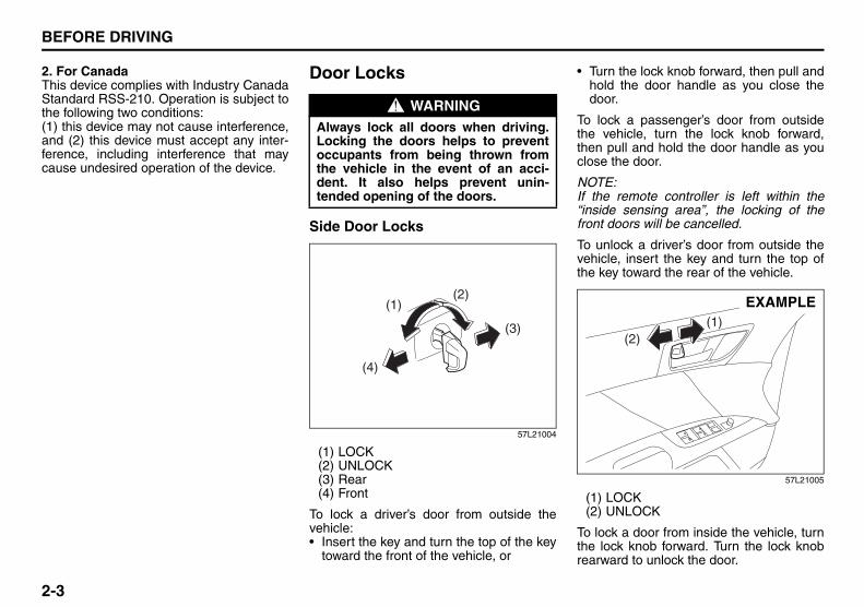
57L21004
(1) LOCK(2) UNLOCK(3) Rear(4) Front
To lock a driver’s door from outside thevehicle:• Insert the key and turn the top of the key
toward the front of the vehicle, or
• Turn the lock knob forward, then pull andhold the door handle as you close thedoor.
To lock a passenger’s door from outsidethe vehicle, turn the lock knob forward,then pull and hold the door handle as youclose the door.
NOTE:If the remote controller is left within the“inside sensing area”, the locking of thefront doors will be cancelled.
To unlock a driver’s door from outside thevehicle, insert the key and turn the top ofthe key toward the rear of the vehicle.
57L21005
(1) LOCK(2) UNLOCK
To lock a door from inside the vehicle, turnthe lock knob forward. Turn the lock knobrearward to unlock the door.
WARNINGAlways lock all doors when driving.Locking the doors helps to preventoccupants from being thrown fromthe vehicle in the event of an acci-dent. It also helps prevent unin-tended opening of the doors.
(2)(1)
(4)
(3) (1)(2)
EXAMPLE
Door Locks: 3, 5, 8

2-4
BEFORE DRIVING
57L20-03E
To lock a rear door from outside the vehi-cle, turn the lock knob forward and closethe door. You do not need to pull and holdthe door handle as you close the door.
Power Door Locking SystemYou can lock and unlock all the doorssimultaneously by:• Turning the key in a driver’s door lock, or• Pushing the power door locking switch
located on the driver’s side or the frontpassenger’s side door panel.
57L21006
(1) LOCK(2) UNLOCK(3) Rear(4) Front
(when using the key)To lock all the doors simultaneously, insertthe key in a driver’s door lock and turn the
top of the key toward the front of the vehi-cle once.
To unlock all the doors simultaneously,insert the key in a driver’s door lock andturn the top of the key toward the rear ofthe vehicle twice.
To unlock only one of the driver’s doors,insert the key in that door lock and turn thetop of the key toward the rear of the vehicleonce.
Driver’s side
57L21007
(1) LOCK(2) UNLOCK
Front passenger’s side
57L21008
(1) LOCK(2) UNLOCK
(when using the power door lockingswitch)To lock or unlock all the doors simulta-neously, depress the front or rear of theswitch (5) or (6), respectively.
NOTE:• You can also lock or unlock all doors by
operating the remote controller. Refer to“Keyless Start System Remote Control-ler” in this section.
• You can also lock or unlock all doors bypushing the request switch on the doorhandle. Refer to “Keyless Start SystemRemote Controller” in this section.
(2)(1)
(4)
(3)
(1)(2)
(5)
EXAMPLE
(1)(2)
(6)
EXAMPLE
Door Locks: 3, 5, 8

2-5
BEFORE DRIVING
57L20-03E
Child Lock System (rear doors)
57L21009
(1) LOCK(2) UNLOCK
Each of the rear doors is equipped with achild lock which can be used to help pre-vent unwanted opening of the door frominside the vehicle. When the lock lever is inthe “LOCK” position (1), the rear door canonly be opened from outside. When thelock lever is in the “UNLOCK” position (2),the rear door can be opened from inside oroutside.
Trunk Lid
57L21010
To open the trunk lid, lift it while pressingthe trunk lid request switch (1).
The trunk lid request switch (1) operateswhen the keyless start system remote con-troller is within the switch’s operatingrange.If the remote controller is within the operat-ing range, you can also unlatch and let thetrunk lid slightly open by holding the“TRUNK LID UNLOCK” button on theremote controller pressed for more than 1second. Refer to “Keyless Start SystemRemote Controller” in this section.The trunk lid request switch (1) operatesonly to open the trunk lid.If you close the trunk lid with the keylessstart system remote controller left in thetrunk with all the doors locked, the trunkwill be automatically unlatched.
57L21011
You can unlock the lid by pushing the trunklid unlatch switch (2).
WARNINGBe sure to place the child lock in the“LOCK” position whenever childrenare seated in the rear.
(1)
(2)
EXAMPLE
(1)
CAUTIONCheck that you have the remote con-troller whenever you close the trunklid, or there is a risk of leaving theremote controller inside the closedtrunk lid.
WARNINGAlways make sure that the trunk lid isclosed and latched securely. Other-wise, it may open unexpectedly whiledriving. Completely closing it alsohelps keep exhaust gases from enter-ing the car.
(2)
Door Locks: 3, 5, 8

2-6
BEFORE DRIVING
57L20-03E
Trunk Lid Lock Switch (if equipped)
57L21061
(3) UNLOCK(4) LOCK
This switch is inside the glove box. If thisswitch is pushed to the down position, thetrunk lid is locked and cannot be opened.Push the switch again to unlock the lid.
Internal Trunk Release
57L21012
There is a release lever located inside thetrunk, on the rear part of the trunk lid. Thislever is for emergency use so that if a per-son, such as a child, gets trapped in thetrunk compartment, he can exit the vehicle.The lever glows in the dark, after a briefexposure to ambient light, so it can befound easily. It is operated by pulling it inthe direction of the arrow.
Keyless Start System Remote ControllerKeyless Start System Remote ControllerThe remote controller enables the followingoperations:• You can lock or unlock the doors by
operating the LOCK/UNLOCK buttonson the remote controller. Refer to theexplanation in this section.
• You can lock or unlock the doors bypushing the request switch on the doorhandle. For details, refer to the explana-tion in this section.
• You can unlatch and let the trunk lidslightly open by pushing and holding the“TRUNK LID UNLOCK” button on theremote controller. Refer to the explana-tion in this section.
(3)
(4)
WARNINGTo help avoid situations where some-one might get trapped in the trunk,keep your vehicle locked when unat-tended, and do not allow anyone toplay in the trunk.
EXAMPLE
Door Locks: 3, 5, 8

2-7
BEFORE DRIVING
57L20-03E
57L21013
(1) “LOCK” button(2) “UNLOCK” button(3) “TRUNK LID UNLOCK” button(4) “PANIC” button
“LOCK” button (1) / “UNLOCK” button(2) functionYou can lock or unlock all doors simulta-neously by operating the remote controllernear the vehicle.
• To lock the doors, push the “LOCK” but-ton (1).
• To unlock the driver’s door, push the“UNLOCK” button (2) once.
• To unlock other doors, wait a second ortwo, then push the “UNLOCK” button (2)a second time. If you “double-click” toofast, the doors will not unlock.
The turn signal lights will flash once whenthe doors are locked.
When the doors are unlocked:• The turn signal lights will flash twice.• If the interior light switch is in the
“DOOR” position, the interior light willturn on for about 15 seconds and thenfade out. If you press the engine switchduring this time, the light will start to fadeout immediately.
Be sure the doors are locked after youoperate the “LOCK” button (1). If no door is opened within about 30 sec-onds after the “UNLOCK” button (2) isoperated, the doors will automatically lockagain.
NOTE:• The maximum operating distance of the
remote controller is about 5 m (16 ft.),but this can vary depending on the sur-roundings, especially near other trans-mitting devices such as radio towers orCB (Citizen’s Band) radios.
• The door locks cannot be operated withthe remote controller if the ignition modehas been changed to “LOCK” (OFF) withthe engine switch, or if any door is open. If any door is open, you cannot lock thedoor by operating the remote controller,however unlock the door.
• You cannot lock the door unless all of thedoor are closed completely.
• If you lose one of the remote controllers,ask your SUZUKI dealer as soon as pos-sible for a replacement. Be sure to haveyour dealer program the new remote
controller code in your vehicle’s memoryso that the old code is erased.
“TRUNK LID UNLOCK” button (3) func-tionPush and hold the “TRUNK LID UNLOCK”button pressed for more than 1 second; thetrunk lid will be unlatched and openslightly.
NOTE:The trunk lid cannot be operated with theremote controller if the engine switch is inany other ignition mode than “LOCK”(OFF).
“PANIC” button (4) functionThis function is to get the attention of oth-ers.Press the “PANIC” button (4) for more than1 second. The headlights and taillights willblink for about 30 seconds. Also, the hornwill sound intermittently for about 30 sec-onds at the same time.To cancel the “PANIC” mode, press anybutton (PANIC, LOCK, UNLOCK orTRUNK LID UNLOCK) on the remote con-troller. You can also press the engineswitch to cancel the “PANIC” mode.
NOTE:The “PANIC” button function will not acti-vate when you have changed the ignitionmode to “ACC” by pressing the engineswitch.
(2)
(1)
(3)
(4)
EXAMPLE
Door Locks: 3, 5, 8
2-8
BEFORE DRIVING
57L20-03E
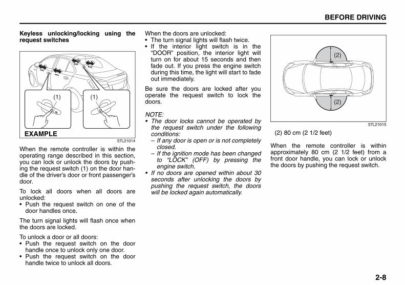
Keyless unlocking/locking using therequest switches
57L21014
When the remote controller is within theoperating range described in this section,you can lock or unlock the doors by push-ing the request switch (1) on the door han-dle of the driver’s door or front passenger’sdoor.
To lock all doors when all doors areunlocked:• Push the request switch on one of the
door handles once.
The turn signal lights will flash once whenthe doors are locked.
To unlock a door or all doors:• Push the request switch on the door
handle once to unlock only one door.• Push the request switch on the door
handle twice to unlock all doors.
When the doors are unlocked:• The turn signal lights will flash twice.• If the interior light switch is in the
“DOOR” position, the interior light willturn on for about 15 seconds and thenfade out. If you press the engine switchduring this time, the light will start to fadeout immediately.
Be sure the doors are locked after youoperate the request switch to lock thedoors.
NOTE:• The door locks cannot be operated by
the request switch under the followingconditions: – If any door is open or is not completely
closed.– If the ignition mode has been changed
to “LOCK” (OFF) by pressing theengine switch.
• If no doors are opened within about 30seconds after unlocking the doors bypushing the request switch, the doorswill be locked again automatically.
57L21015
(2) 80 cm (2 1/2 feet)
When the remote controller is withinapproximately 80 cm (2 1/2 feet) from afront door handle, you can lock or unlockthe doors by pushing the request switch.
(1) (1)
EXAMPLE
(2)
(2)
Windows: 3, 8

2-9
BEFORE DRIVING
57L20-03E
NOTE:• If the remote controller is outside the
request switch operating rangedescribed above, you will not be able tooperate the request switch.
• If the battery of the remote controllerruns down or there are strong radiowaves or noise, the request switch oper-ating range may be reduced or theremote controller may be inoperative.
• If the remote controller is too close to thedoor, the request switches may not oper-ate.
• If a spare remote controller is in the vehi-cle, the request switches may not oper-ate normally.
• The remote controller will only operate arequest switch if it is within the switch’soperating range. For example, if theremote controller is within the operatingrange of the driver’s door request switchbut not the front passenger’s doorrequest switch, the driver’s door switchcan be operated but the front passen-ger’s door switch cannot be operated.
NOTE:The keyless start system may not functioncorrectly in certain environments or undercertain operating conditions such as thefollowing:• When there are strong signals coming
from a television, power station or a cel-lular phone.
• When the remote controller is in contactwith or covered by a metal object.
• When a radio wave type remote keylessentry is used nearby.
• When the remote controller is placednear an electronic device such as per-sonal computer.
Some additional precautions you shouldtake and information you should be awareof are: • Make sure the key is stowed in the
remote controller. If the remote controllerbecomes unreliable, you will not be ableto lock or unlock the doors, or start theengine.
• Be sure that the driver always carries theremote controller.
• If you lose one of the remote controllers,ask an authorized SUZUKI dealer assoon as possible for a replacement. Besure to have your dealer program thenew remote controller code in your vehi-cle’s memory so that the old code iserased, or perform the programming pro-cedure yourself according to the instruc-tions in this section.
• You can use up to four remote controllersand keys for your vehicle. Ask an autho-rized SUZUKI dealer for details.
• The battery life of the remote controlleris about two years, but it can varydepending on usage conditions.
CAUTIONThe remote controller is a sensitiveelectronic instrument. To avoid dam-aging the remote controller:• Do not expose it to impacts, mois-
ture or high temperature such as byleaving it on the dashboard underdirect sunlight.
• Keep the remote controller awayfrom magnetic objects such as atelevision.
Windows: 3, 8

2-10
BEFORE DRIVING
57L20-03E
Request Switch Warning BuzzerThis outside buzzer beeps for about 2 sec-onds in the following conditions to warnyou that the request switch is not working:• The request switch is pressed after all
doors are closed with the ignition modechanged to “ACC” or “ON” by pressingthe engine switch.
• The request switch is pressed in any ofthe following conditions after changingthe ignition mode to “LOCK” (OFF) bypressing the engine switch.– The remote controller is left inside the
vehicle.– Any of the doors is open.
Press the request switch again after doingthe following:With the ignition mode changed to “LOCK”(OFF) by pressing the engine switch, bringout the remote controller if it is inside thevehicle and check that all doors are com-pletely closed.
Remote Controller Reminder FunctionWhen you lock a door without using thekey, this function prevents it from beinglocked if the remote controller is left insidethe vehicle.
With the remote controller inside the vehi-cle, locking of the driver’s and passenger’sdoors made with the power door lockingsystem or door lock knobs will be can-celled if either of the doors is open.
NOTE:• Whenever you lock a door without using
the key, check that you have the remotecontroller with you. This is a good habitto prevent locking a door with the remotecontroller left behind.
• The remote controller reminder functionis activated when you press the engineswitch to change the ignition mode to“ACC” or “ON” anywhere the remotecontroller is placed.
Vehicle Inside Area Where RequestSwitch Warning Buzzer/Remote Con-troller Reminder Function WorksInside the vehicle, the remote controllermay be located in any place within the indi-cated “inside sensing area” (1) (not includ-ing the instrument panel top and trunk) forthe request switch warning buzzer/remotecontroller reminder function to work.
57L21017
(1)
Windows: 3, 8Mirrors: 3, 8

2-11
BEFORE DRIVING
57L20-03E
NOTE:• Even with the remote controller within
the “inside sensing area”, the requestswitch warning buzzer/remote controllerreminder function may not work underany of the following conditions as thepresence of the remote controller maynot be sensed:– The battery of the remote controller is
low.– The remote controller is influenced by
strong radio waves or noise.– The remote controller is in contact with
or covered by a metallic object.– The remote controller is in the glove
box or a stowage for small articlessuch as a door pocket.
– The remote controller is on the top orin front of the instrument panel, in thesun visor pocket or on the floor.
• The remote controller may be sensedunder any of the following conditionseven when the controller is not within the“inside sensing area”. The requestswitch warning buzzer/remote controllerreminder function will then work.– The remote controller is outside the
vehicle but very close to it.– The remote controller is on the instru-
ment panel top or in the trunk.
Keyless unlocking/locking using thetrunk lid request switch
57L21010
57L21018
(2) 80 cm (2 1/2 feet)
When the remote controller is withinapproximately 80 cm (2 1/2 feet) from thetrunk lid request switch, you can open thetrunk lid by pushing and holding the trunklid request switch (1).
NOTE:• If the remote controller is outside the
trunk lid request switch operating rangedescribed above, you will not be able tooperate the switch.
• If the battery of the remote controllerruns down or there are strong radiowaves or noise, the trunk lid requestswitch operating range may be reducedor the remote controller may be inopera-tive.
• If the remote controller is too close to thetrunk lid, the trunk lid request switch maynot operate.
• If a spare remote controller is in thetrunk, the trunk lid request switch maynot operate normally.
(1)
(2) CAUTIONThe remote controller is a sensitiveelectronic instrument. To avoid dam-aging the remote controller:• Do not expose it to impacts, mois-
ture or high temperature such as byleaving it on the dashboard underdirect sunlight.
• Keep the remote controller awayfrom magnetic objects such as atelevision.
Mirrors: 3, 8Seat Adjustment: 3

2-12
BEFORE DRIVING
57L20-03E
NOTE:The keyless start system may not functioncorrectly in certain environments or undercertain operating conditions such as thefollowing:• When there are strong signals coming
from a television, power station or a cel-lular phone.
• When the remote controller is in contactwith or covered by a metal object.
• When a radio wave type remote keylessentry is used nearby.
• When the remote controller is placednear an electronic device such as per-sonal computer.
Some additional precautions you shouldtake and information you should be awareof are: • Make sure the key is stowed in the
remote controller. If the remote controllerbecomes unreliable, you will not be ableto lock or unlock the doors, or start theengine.
• Be sure that the driver always carries theremote controller.
• If you lose one of the remote controllers,ask an authorized SUZUKI dealer assoon as possible for a replacement. Besure to have your dealer program thenew remote controller code in your vehi-cle’s memory so that the old code iserased, or perform the programming pro-cedure yourself according to the instruc-tions in this section.
• You can use up to four remote controllersand keys for your vehicle. Ask an autho-rized SUZUKI dealer for details.
• The battery life of the remote controlleris about two years, but it can varydepending on usage conditions.
Remote Controller Reminder Function(for Trunk)This function prevents the remote control-ler from being left under a locked trunk lid.• If you attempt to lock the trunk lid with
the remote controller left inside the trunkand the vehicle in the following condition,the function automatically unlocks andslightly opens the lid:– Vehicle is parked with all doors closed
and locked.
Trunk Inside Area Where Remote Con-troller Reminder Function (for Trunk)Works
57L21019
CAUTIONCheck that you have the remote con-troller whenever you close the trunklid, or there is a risk of leaving theremote controller inside the closedtrunk lid.
(1)
Seat Adjustment: 3

2-13
BEFORE DRIVING
57L20-03E
NOTE:• Even with the remote controller within
the “trunk inside sensing area” (1), theremote controller reminder function (fortrunk) may not work under any of the fol-lowing conditions as the presence of theremote controller may not be sensed:– The battery of the remote controller is
low.– The remote controller is influenced by
strong radio waves or noise.– The remote controller is in contact with
or covered by a metallic object.– The remote controller is in a corner of
the trunk.• The remote controller may be sensed
under the following condition even whenthe controller is not within the “trunkinside sensing area”. The remote con-troller reminder function (for trunk) willthen work.– The remote controller is outside the
vehicle but very close to the trunk.
Replacement of the batteryIf the remote controller becomes unreli-able, replace the battery.
To replace the battery of the remote con-troller:
57L21022
1) Insert a flat blade screwdriver coveredwith a soft cloth in the slot of the remotecontroller and pry it open.
57L21023
(1) Lithium disc type battery: CR2032 or equivalent
2) Replace the battery (1) so its + terminalfaces the bottom of the case as shownin the illustration.
3) Close the remote controller firmly.4) Make sure the door locks can be oper-
ated with the remote controller.5) Dispose of the used battery properly
according to applicable rules or regula-tions. Do not dispose of lithium batter-ies with ordinary household trash.
EXAMPLE (1)
EXAMPLE
Seat Adjustment: 3Head Restraints: 3

2-14
BEFORE DRIVING
57L20-03E
1. For USAThis device complies with Part 15 of theFCC Rules. Operation is subject to the fol-lowing two conditions:1) This device may not cause harmful
interference, and2) This device must accept any interfer-
ence received, including interferencethat may cause undesired operation.
NOTE:Changes or modifications not expresslyapproved by the party responsible for com-pliance could void the user’s authority tooperate the equipment.
2. For CanadaThis device complies with Industry CanadaStandard RSS-210. Operation is subject tothe following two conditions:1) This device may not cause interference,
and2) This device must accept any interfer-
ence, including interference that maycause undesired operation of thedevice.
The term “IC:” before the certification/reg-istration number only signifies that theIndustry Canada technical specificationswere met.
Theft Deterrent Alarm SystemThe theft deterrent alarm system is armedin about 20 seconds after you lock thedoors using the keyless start systemremote controller or by pushing the requestswitch on the driver’s or front passenger’sdoor handle. (The system, however, is notarmed when the engine hood or trunk lid isopen.)Once the system is armed, any attempt toopen a door by using any other means (*)than the keyless start system remote con-troller or the request switch will cause thealarm to be triggered. * These means include the following:
– The key– The lock lever on a door– The power door lock knob– The trunk lid unlatch switch– The engine hood release handle
WARNINGSwallowing a lithium battery maycause serious internal injury. Do notallow anyone to swallow a lithiumbattery. Keep lithium batteries awayfrom children and pets. If swallowed,contact a physician immediately.
CAUTIONThe remote controller is a sensitiveelectronic instrument. To avoid dam-aging it, do not expose it to dust ormoisture or tamper with internalparts.
Head Restraints: 3Seat Belts and Child Restraint Systems: 3

2-15
BEFORE DRIVING
57L20-03E
NOTE:• The theft deterrent alarm system gener-
ates alarms when any of the predeter-mined conditions is met. However, thesystem does not have any function ofblocking unauthorized entry into yourvehicle.
• Always use the keyless start systemremote controller or the request switch tounlock the doors when the theft deter-rent alarm system has been armed.Using a key instead will trigger thealarm.
• If a person who does not know the theftdeterrent alarm system is going to driveyour vehicle, we recommend you toexplain the system and its operation tothe person, or disable the system before-hand. Mistakenly triggering the alarmmay cause a nuisance to others.
• Even if the theft deterrent alarm systemis armed, you should still be careful toguard against theft. Do not leave moneyor things of value in your vehicle.
How to arm the theft deterrent alarmsystem (when enabled)Lock the doors using the keyless start sys-tem remote controller or by pushing therequest switch. The theft deterrent light (1)will start flashing, and the theft deterrentalarm system will be armed in about 20seconds. While the system is being armed, the indi-cator continues to flash at approximately 2-second intervals.
57L30094
NOTE:• To prevent the alarm from being acciden-
tally triggered, avoid arming it while any-one remains inside the vehicle. Thealarm will be triggered if any personinside unlocks a door by operating thelock lever or power door locking switch.
• The theft deterrent alarm system is notarmed when all doors are locked usingthe key from outside, or using the doorlock levers or the power door lockingswitch from inside.
• If the timer locking function is activated,the system will be automatically armedat the preset time unless the theft deter-rent alarm system has been disabled.
How to disarm the theft deterrent alarmsystemSimply unlock the doors using the keylessstart system remote controller or by push-ing the request switch. The theft deterrentlight will go out, indicating that the theftdeterrent alarm system is disarmed.
(1)
Seat Belts and Child Restraint Systems: 3

2-16
BEFORE DRIVING
57L20-03E
How to stop the alarmShould the alarm be triggered accidentally,change the ignition mode to “ON” by press-ing the engine switch. The alarm will thenstop.
NOTE:• Even after the alarm has stopped, if you
lock the doors using the keyless startsystem remote controller or by pushingthe request switch, the theft deterrentalarm system will be rearmed with adelay of about 20 seconds.
• If you disconnect the battery while thetheft deterrent alarm system is in thearmed condition or the alarm is actuallyin operation, the alarm will be triggeredor re-triggered when the battery is thenreconnected, although, in the latter case,the alarm remains stopped for the periodbetween disconnection and reconnec-tion of the battery.
• Even after the alarm has stopped at theend of the predetermined operation time,it will be triggered again if any door isopened without disarming the theftdeterrent alarm system.
Checking whether the alarm has beentriggered during parkingIf the alarm was triggered due to an unau-thorized entry into the vehicle and you thenchange the ignition mode to “ON” by press-ing the engine switch, the theft deterrentlight will flash rapidly for about 8 secondsand a buzzer will beep 4 times during thisperiod. If this happens, check whether yourvehicle has been broken into while youwere away from it.
Enabling and disabling the theft deter-rent alarm systemThe theft deterrent alarm system can beeither “enabled” or “disabled”.
When enabled (factory setting)When the system is enabled, it causes thehazard warning lights to flash for about 40seconds if any of the alarm trigger condi-tions is met. The system also causes theinterior buzzer to beep intermittently forabout 10 seconds, which is followed byintermittent sounding of the horn for about30 seconds. *The theft deterrent light continues to flashduring this time.
When disabledWhen the system is disabled, it stays dis-armed even if you perform any systemarming operation.
How to switch the state of the theftdeterrent alarm systemYou can switch the theft deterrent alarmsystem from the enabled state to the dis-abled state, and vice versa, using the fol-lowing method.
57L21020
(2) UNLOCK(3) LOCK
57L21021
(3)(2)
(1)
EXAMPLE
(4)
(5)4 times
EXAMPLE
Seat Belts and Child Restraint Systems: 3

2-17
BEFORE DRIVING
57L20-03E
1) With the ignition mode changed to “ON”by pressing the engine switch, close allthe doors as well as the engine hoodand the trunk lid and push the unlockend (backward end) of the power doorlocking switch (1) of the driver’s door.Turn the knob control on the lightingcontrol lever to the OFF position (4).
NOTE:All operations included in the followingsteps 2) and 3) must be completed within15 seconds.
2) Turn the knob control on the lightingcontrol lever to the position (5) andthen to the OFF position (4). Repeatthis operation 4 times with the controlfinally set to the OFF position.
3) Push the lock end (forward end) of thepower door lock switch (1) to lock thedoors, and then the unlock end (back-ward end) to unlock the doors. Repeatthese operations 3 times and finallypush the lock end of the switch.
Every time you perform the series of theabove steps, the state of the theft deterrentalarm system changes from the currentlyselected one to the other. You can checkwhether the system is enabled or disabledby the number of interior buzzer beeps atthe end of the procedure as follows.
NOTE:• You cannot disable the theft deterrent
alarm system while it is in the armedcondition.
• If you fail to complete the operations instep 2) and 3) within 15 seconds, per-form the procedure again from thebeginning.
• Make sure all doors are closed whenperforming the above procedure.
WindowsPower Window ControlsDriver’s side
57L21024
The power windows can be operated whenthe ignition mode is changed to “ON” bypressing the engine switch.
The driver’s door has switches (1), (2), (4),(5), to operate the driver’s window, thefront passenger’s window, the rear left win-dow and the rear right window, respec-tively.
System state Number of beeps
Disabled Once
Enabled 4 times
(4)
(1)
(2)
(5)
EXAMPLE
Seat Belts and Child Restraint Systems: 3

2-18
BEFORE DRIVING
57L20-03E
Passenger’s door, Rear doors
57L21025
The passenger’s door has a switch (3) tooperate the passenger’s window.
81A009
To open a window, push the top part of theswitch and to close the window lift up thetop part of the switch.
The driver’s and passenger’s windowshave “auto-down” and “auto-up” featuresfor added convenience (at tall booths ordrive-through restaurants, for example).This means the driver or passenger canopen or close the window without holdingthe window switch in the “Down” or “Up”position. Press down or lift up the driver’sor passenger’s window switch completelyand release it. To stop the window before itreaches the full-down or full-up position,pull up or push down the switch briefly.
Lock switch
57L21026
(7) UNLOCK(8) LOCK
The driver’s door also has a lock switch (6)for the passenger’s window(s). When youpush in the lock switch, the passenger’swindow(s) cannot be raised or lowered byoperating any of the switches (2), (3), (4) or(5). To restore normal operation, releasethe lock switch by pushing the switchagain.
(3)
EXAMPLE CLOSE
OPEN
(6)
(7)
(8)
EXAMPLE
Seat Belts and Child Restraint Systems: 3

2-19
BEFORE DRIVING
57L20-03E
NOTE:The driver’s and passenger’s windows canbe operated for 30 seconds even after theignition mode is changed from “ON” to“ACC” or “LOCK” (OFF) by pressing theengine switch. However, if either of thefront doors is opened within this 30-secondperiod, the windows cannot be operatedthereafter.If you drive with one of the rear windowsopen, you may hear a loud sound causedby air vibration. To reduce the sound, open
the driver’s or front passenger’s window, ornarrow the rear window opening.
Initialization of Auto-Down/Up FunctionIf the auto-down/up function does not workfor some reason, initialize the function asinstructed below. Note that the initializationmust be performed using the switch foreach window; the function of the passen-ger’s door window cannot be initializedusing the switch of the driver’s door win-dow.
1) Start the engine.2) Open the front window fully by holding
the window switch in the “Down” posi-tion.
3) Close the front window by holding theswitch in the “Up” position, and keepholding the switch for 2 seconds afterthe window fully closed.
4) Check the front window if the auto-down/up feature work.
Pinching Prevention Function (if equipped)The front window is equipped with thepinching prevention function. The functiondetects a foreign object caught in the win-dow while being closed by the “auto-up”feature, which you can close the windowwithout holding the window switch in the“Up” position, and stops the window clos-ing to prevent damage.
WARNING• You should always lock the passen-
ger’s window operation when thereare children in the vehicle. Childrencan be seriously injured if they getpart of their body caught by thewindow during operation.
• To avoid injuring an occupant bywindow entrapment, be sure nopart of the occupant’s body suchas hands or head is in the path ofthe electric windows when closingthem.
• Always take the keyless start sys-tem remote controller with youwhen leaving the vehicle even ifonly for a short time. Also do notleave children alone in a parkedvehicle. Unattended children coulduse the electric window switchesand get trapped by the window.
WARNINGTo avoid injuring an occupant by win-dow entrapment, be sure no part ofthe occupant’s body such as handsor head is in the path of the electricwindow when closing it.The function may not detect theobject depending on size, hardness,and position of the object caught bythe closing window.
CAUTION• The pinching prevention function
does not act while you are holdingthe window switch in the “Up” posi-tion.
• The pinching prevention functionmay not detect an object caught inthe window where just before thewindow fully closed.
Seat Belts and Child Restraint Systems: 3

2-20
BEFORE DRIVING
57L20-03E
NOTE:Even if you cannot close the window by theauto-up feature because there may besomething wrong with the pinching preven-tion function, you can close the window byholding the window switch in the “Up” posi-tion. If you drive in extreme off-road condition,the pinching prevention function may oper-ate accidentally because the windowreacts to vehicle jolting.
MirrorsInside Rearview Mirror (if equipped)
65D410
65D409
(2) Day driving(3) Night driving
You can adjust the inside rearview mirrorby hand so as to see the rear of your vehi-cle in the mirror. To adjust the mirror, setthe selector tab (1) to the day position,then move the mirror up, down or sidewaysby hand to obtain the best view.
When driving at night, you can move theselector tab to the night position to reduceglare from the headlights of vehiclesbehind you.
CAUTIONThe pinching prevention function willnot be activated until the initializationis complete.• Do not strike or otherwise give
shock to the window during initial-ization.
• Initialization is impossible while thevehicle is in motion.
If the auto-up feature would not workafter initialization, there might besomething wrong with the pinchingprevention function. Have your vehi-cle inspected by an authorizedSUZUKI dealer.
(1)
(2) (3)
WARNING• Always adjust the mirror with the
selector set to the day position.• Only use the night position if it is
necessary to reduce glare from theheadlights of vehicles behind you.Be aware that in this position youmay not be able to see someobjects that could be seen in theday position.
Seat Belts and Child Restraint Systems: 3
CAUTION
• Never spray any liquid directly onthe anti-glare rearview mirror asthis may damage the internalelectronic components.
• Always clean the mirror with a soft towel. Dampen with clean water

2-21
BEFORE DRIVING
57L20-03E
Auto dimming rearview mirror (if equipped)With HomeLink® Wireless Control Sys-tem
57L21027
You can adjust the auto dimming rearviewmirror by hand so you can see to the rearof your vehicle in the mirror. This rearviewmirror has a function of automaticallyreducing glare from the lights of vehiclesbehind you. The function works when theignition mode has been changed to “ON”by pressing the engine switch.• The mirror is always set to the automatic
dimming mode when the engine switchis in the “ON” mode.
• When the “ON” switch (2) is pushed, thegreen indicator (1) is lit, indicating thatthe mirror is set to the automatic dim-ming mode. To cancel the automaticdimming mode, push the “OFF” switch(3); the indicator (1) then goes out.
• The auto dimming rearview mirror isautomatically deactivated while the gear-shift lever is in the “R” position.
57L21028
Without HomeLink® Wireless ControlSystem
57L30019
You can adjust the auto dimming rearviewmirror by hand so you can see to the rearof your vehicle in the mirror. This rearviewmirror has a function of automaticallyreducing glare from the lights of vehiclesbehind you. The function works when theignition mode has been changed to “ON”by pressing the engine switch.• The mirror is always set to the automatic
dimming mode when the engine switchis in the “ON” mode.
• When the “AUTO” switch (2) is pushed,the green indicator (1) is lit, indicatingthat the mirror is set to the automaticdimming mode. To cancel the automaticdimming mode, push the “AUTO” switch(2); the indicator (1) then goes out.
(2) (3)(1)
CAUTION• Do not touch or cover the sensor
(4) since this may impair normaloperation of the system. Blockingglare from the sensor with anobject such as a shade, sticker,accessory or baggage may alsoimpair proper operation of the sys-tem.
• Do not hook anything heavy on themirror, or the mirror may breakunder the weight.
(4)(4) (2)(1)
Seat Belts and Child Restraint Systems: 3

2-22
BEFORE DRIVING
57L20-03E
• The auto dimming rearview mirror isautomatically deactivated while the gear-shift lever is in the “R” position.
57L30020
Outside Rearview Mirrors
79J033
Adjust the outside rearview mirrors so youcan just see the side of your vehicle in themirrors.
The passenger’s side mirror is a convex(curved surface) mirror. Objects seen inthis mirror will look smaller and appear far-ther away than when seen in a flat mirror.
Power Mirror Control
57L21029
The switch to control the power rearviewmirrors is located on the driver’s doorpanel. You can adjust the mirrors afterpressing the engine switch to change theignition mode to “ACC” or “ON”. To adjustthe mirrors:
1) Move the selector switch to the left orright to select the mirror you wish toadjust.
2) Press the outer part of the switch thatcorresponds to the direction you wish tomove the mirror.
3) Return the selector switch to the centerposition to help prevent unintendedadjustment.
CAUTION• Do not touch or cover the sensor
(3) since this may impair normaloperation of the system. Blockingglare from the sensor with anobject such as a shade, sticker,accessory or baggage may alsoimpair proper operation of the sys-tem.
• Do not hook anything heavy on themirror, or the mirror may breakunder the weight.
(3)(3)
WARNINGBe careful when judging the size ordistance of a vehicle or other objectseen in the side convex mirror. Beaware that objects look smaller andappear farther away than when seenin a flat mirror.
EXAMPLE
(2)
(4)
(3)
(1) (1)
(3)(2)
(4)
EXAMPLE
Seat Belts and Child Restraint Systems: 3

2-23
BEFORE DRIVING
57L20-03E
NOTE:If your vehicle is equipped with the heatedoutside rearview mirrors, refer to “HeatedRear Window and Heated Outside Rear-view Mirrors (if equipped) Switch” in thissection.
Front SeatsStandard Seat (if equipped)Adjusting seat position
57L21109
The adjustment lever for each front seat islocated under the front of the seat. Toadjust the seat position, pull up on theadjustment lever and slide the seat forwardor rearward. After adjustment, try to movethe seat forward and rearward to ensurethat it is securely latched.
WARNINGNever attempt to adjust the driver’sseat or seatback while driving. Theseat or seatback could move unex-pectedly, causing loss of control.Make sure that the driver’s seat andseatback are properly adjustedbefore you start driving.
WARNINGTo avoid excessive seat belt slack,which reduces the effectiveness ofthe seat belts as a safety device,make sure that the seats are adjustedbefore the seat belts are fastened.
Seat Belts and Child Restraint Systems: 3

2-24
BEFORE DRIVING
57L20-03E
57L21110
If the driver’s seat is equipped with a seatheight adjuster lever on the outboard sideof the seat, raise or lower the seat by pull-ing up or down the adjuster lever.
Adjusting seatbacks
57L21111
To adjust the seatback angle of front seats,pull up the lever on the outboard side ofthe seat, move the seatback to the desiredposition, and release the lever to lock theseatback in place. After adjustment, trymoving the seatback to make sure it issecurely locked.
Power Seat (if equipped)Adjusting seat positionWARNING
All seatbacks should always be in anupright position when driving, or seatbelt effectiveness may be reduced.Seat belts are designed to offer maxi-mum protection when seatbacks arein the upright position.
WARNINGNever attempt to adjust the driver’sseat or seatback while driving. Theseat or seatback could move unex-pectedly, causing loss of control.Make sure that the driver’s seat andseatback are properly adjustedbefore you start driving.
WARNINGTo avoid excessive seat belt slack,which reduces the effectiveness ofthe seat belts as a safety device,make sure that the seats are adjustedbefore the seat belts are fastened.
CAUTIONDo not place any object under theseat. The object may cause damageto the seat if caught under it.
Seat Belts and Child Restraint Systems: 3

2-25
BEFORE DRIVING
57L20-03E
57L21030
Sliding the multi-function control switch (1)located on the outside of the driver’s seatforward or backward changes the fore-and-aft position of the seat.
57L21031
• Lifting up the front end of the multi-func-tion control switch causes the front partof the seat to rise.
• Pushing down the front end of the switchcauses the front part of the seat to lower.
• Lifting up the rear end of the switchcauses the whole seat to rise and thewhole seat to move forward at the sametime.
• Pushing down the rear end of the switchcauses the whole seat to lower and thewhole seat to move backward at thesame time.
Adjusting seatbacks
57L21032
Tilt the reclining switch (2) forward or rear-ward to adjust the angle of the seatback.
(1)
(1)
WARNINGAll seatbacks should always be in anupright position when driving, or seatbelt effectiveness may be reduced.Seat belts are designed to offer maxi-mum protection when seatbacks arein the upright position.
(2)
Seat Belts and Child Restraint Systems: 3

2-26
BEFORE DRIVING
57L20-03E
Adjusting the Lumbar Support (if equipped)
57L21033
Use the lumbar support switch (3) locatedat the rear of the reclining switch to adjustthe force with which the seatback supportsthe lumbar area of your back.• Push the front button on the switch for
firmer support.• Push the rear button on the switch for
softer support.
Seat Position Memory System (if equipped)Power seat (if equipped)This function allows you to restore yourpreferred preprogrammed seat position atthe touch of one of the three position but-tons, which are provided on the top of theswitch block on the outside of the driver’sseat. One seat position can be pro-grammed to each button, so a total of threedifferent positions can be stored in mem-ory.
How to program a seat position
57L21034
1) Adjust the seat position as desired.2) Within 5 seconds after pressing the
memory button (4) or while pressing thebutton, press one of the position but-tons 1 – 3 (5). A buzzer will sound whenthe position has been successfully pro-grammed.
NOTE:The seat position programmed to a posi-tion button is overwritten if you programanother seat position to the same button.
How to restore the seat to a memorizedposition1) Press the engine switch to change the
ignition mode to “ACC” or “ON”.2) Press the desired position button. A
buzzer will sound both when the systemstarts and completes the process forrestoring the memorized position. Theseat is now automatically set to theselected position.
NOTE:• If you press any of the following buttons
during the process of restoring a memo-rized position, the system stops the pro-cess.– Memory button– Position button of any other number– Any of the seat position adjusting
switches• Restoring the seat to a memorized posi-
tion is possible only when all of the fol-lowing conditions are met:– The ignition mode has been changed
to “ACC” or “ON” by pressing theengine switch.
– CVT: The gearshift lever is in the “P”position.Manual Transaxle: The parking brakeis applied.
– Vehicle speed is 2 mph (3 km/h) orlower.
(3)
(5)
(4)
Seat Belts and Child Restraint Systems: 3

2-27
BEFORE DRIVING
57L20-03E
Head Restraints
80J001
Head restraints are designed to helpreduce the risk of neck injuries in case ofan accident.Adjust the head restraint to the positionwhich places the center of the headrestraint closest to the top of your ears. Ifthis is not possible for very tall passengers,adjust the head restraint as high as possi-ble.
Front
57L21035
Each front seat is equipped with a headrestraint.
57L21036
(1) head restraint(2) bars(3) release knob
To raise the head restraint, pull upward onthe restraint until it clicks. To lower therestraint, push down on the restraint whileholding in the release knob (3). If a headrestraint must be removed (for cleaning,replacement, etc.), push in the releaseknob and pull the head restraint all the wayout.
NOTE:It may be necessary to recline the seat-back to provide enough overhead clear-ance to remove the head restraint.
WARNINGAll occupants, including the driver,should not operate a vehicle or sit ina vehicle’s seat until the headrestraints are placed in their properpositions in order to minimize therisk of severe injury in the event of acrash.
WARNINGAll head restraints must be rein-stalled to properly protect vehicleoccupants.
WARNING• Never drive the vehicle with the
head restraints removed.• Do not attempt to adjust the head
restraint while driving.
EXAMPLE
(1)
(3)
(2)
Seat Belts and Child Restraint Systems: 3

2-28
BEFORE DRIVING
57L20-03E
57L21037
To reinstall the head restraint, insert thehead restraint bars into the holes (4) andpush the head restraint down.
Front Seat Heater (if equipped)
57L21038
(1) Driver’s seat heater switch(2) Passenger’s seat heater switch
With the ignition mode changed to “ON” bypressing the engine switch, push in one orboth of the seat heater switches to warmthe corresponding seat(s). • When a seat heater switch is pushed,
the heater inside the corresponding seatoperates.
• Heating intensity can be adjusted to oneof three levels: L (low), M (medium) andH (high).
• Every time you press the seat heaterswitch, the indicators inside the switchlight one at a time in the followingsequence to indicate the selected heateroperation.– L (low): Weak heating (Only the L indi-
cator lights.)– M (medium): Moderate heating (The L
and M indicators light.)– H (high): Strong heating (The L, M and
H indicators light.)– OFF: Heater turned off (No indicator
illuminates.)
86G064
(4)
(2)(1)
Seat Belts and Child Restraint Systems: 3

2-29
BEFORE DRIVING
57L20-03E
Rear SeatsHead RestraintsHead restraints are designed to helpreduce the risk of neck injuries in the caseof an accident.
NOTE:It may be necessary to fold forward theseatback to provide enough overheadclearance to remove the head restraint.
Adjust the head restraint to the positionwhich places the center of the headrestraint closest to the top of your ears. Ifthis is not possible for very tall passengers,adjust the head restraint as high as possi-ble.
Rear
57L21039
Your vehicle is equipped with three headrestraints on the rear seat.
WARNINGImproperly using the seat heater canbe hazardous. An occupant can suf-fer burns even if the heating tempera-ture is fairly low, if the occupant iswearing thin pants, a thin skirt orshorts and leaves the heater on forlong periods.Avoid using the seat heater for theseoccupants:• People who have reduced feeling in
their legs, including the elderly orthose with certain disabilities.
• Small children, or anyone with sen-sitive skin.
• People who are asleep or under theinfluence of alcohol or other drugswhich make them tired.
CAUTIONTo avoid damaging the heater ele-ment:• Do not subject the front seats to
heavy impacts, such as childrenjumping on them.
• Do not cover the seat with anyinsulating materials such as blan-kets or cushions.
WARNINGAll occupants, including the driver,should not operate a vehicle or sit ina vehicle’s seat until the headrestraints are placed in their properpositions in order to minimize therisk of severe injury in the event of acrash.
WARNINGAll head restraints must be rein-stalled to properly protect vehicleoccupants.
WARNING• Never drive the vehicle with the
head restraints removed.• Do not attempt to adjust the head
restraint while driving.
Seat Belts and Child Restraint Systems: 3

2-30
BEFORE DRIVING
57L20-03E
Left and right seating places
57L30058
If the head restraint is tipped forward, raiseit upright.
57L21040
(1) head restraint(2) bars(3) release knob
To raise the rear head restraint, pullupward on the restraint until it clicks. Tolower the restraint, push down on therestraint while holding in the release knob(3).
57L30033
When the head restraints must beremoved, use the following methods:For the left and right seating places, tip thehead restraint forward and then pull it upwhile holding the release knob pushed.
NOTE:You cannot remove the head restraint with-out tipping it forward; in the upright posi-tion, the head restraint touches the cabinsealing before it can be removed.
(3)(1)
(2)
WARNINGNever allow anyone to sit on the rearseat with the head restraints removedor tipped forward.
Seat Belts and Child Restraint Systems: 3

2-31
BEFORE DRIVING
57L20-03E
To reinstall the head restraints, do the fol-lowing:For the left and right seating places, insertthe head restraint while still in its forward-tipped position (do not face the backsideforward) into the seatback until it locks.Then tilt it back to the normal position. Theheight of the reinstalled head restraintsmust be adjusted properly before use.
NOTE:It is recommended to tilt the headrestraints forward to have a better rearwardview.
Central seating place
57L30061
When there is a passenger in the centralseating place, pull up the head restraint byhand and make sure it is securely lockedbefore starting to drive.
57L30060
When there is no occupant in the centralseating place, push down the headrestraint fully while holding the releaseknob (1) pressed.
When the head restraints must beremoved, use the following methods:Pull the head restraint up and out of theseat while holding the release knobpressed.
WARNINGDo not leave the removed headrestraints unfixed in the cabin. Theymay hit against you and passengersin the event of hard braking or othersimilar instances, increasing the riskof an accident.
WARNINGAlways check that the head restraintis firmly in position after installing it.Avoid installing it with the backsidefacing forward. A wrongly facinghead restraint does not provide theintended protection, and also itsheight cannot be adjusted.
WARNINGDo not allow anyone to sit in the cen-ter seating place with the headrestraint removed or in the stowedposition.
WARNINGDo not leave the removed headrestraints unfixed in the cabin. Theymay hit against you and passengersin the event of hard braking or othersimilar instances, increasing the riskof an accident.
(1)
Seat Belts and Child Restraint Systems: 3

2-32
BEFORE DRIVING
57L20-03E
To reinstall the head restraints, do the fol-lowing:With the correct side facing forward, insertthe head restraint into the seat until it islocked at a height. Then adjust the heightas desired.
Folding Rear SeatsThe rear seats of your vehicle can be foldedforward to provide additional cargo space.
To fold the rear seats forward:
57L30037
1) Stow the seatbelt for the rear centerseat in the retractor behind the headrestraint and retain its end in the holderso that the seatback for the left seatingplace can be folded.
2) Adjust all the head restraints to the low-est positions. In addition, tip forward thehead restraints for the right and leftseats.
3) Detach the seat belts for the right andleft seats from the seatbacks as shownin the illustration so the belts are notcaught when the seatbacks are moved.
57L30038
4) Pull the release lever (1) on the top ofeach split seat, and fold the seatbacksforward.
WARNINGAlways check that the head restraintis firmly in position after installing it.Avoid installing it with the backsidefacing forward. A wrongly facinghead restraint does not provide theintended protection, and also itsheight cannot be adjusted.
CAUTIONAfter folding the rear seatback for-ward, do not allow any foreign mate-rial to enter the lock opening. Thismay cause damage to the inside ofthe lock and prevent the seatbackfrom being locked securely.
(1)
Seat Belts and Child Restraint Systems: 3

2-33
BEFORE DRIVING
57L20-03E
To return the seat to the normal position,follow the procedure below.
57L21041
(1) LOCK(2) UNLOCK
Raise the seatback until it locks into place.
After returning the seat, try moving theseatback to make sure they are securelylatched.
WARNINGLuggage or other cargo should bestowed in the luggage compartmentwith the rear seat in an upright posi-tion, whenever possible. If you needto carry cargo in the passenger com-partment with the rear seat backfolded forward, be sure to secure thecargo or it may be thrown about,causing injury. Never pile cargohigher than the seatbacks.
WARNINGWhen returning the rear seatback tothe normal position, be careful thatyour finger is not caught between thelock and the striker.
CAUTIONWhen returning the rear seatback tothe normal position, make sure thatthere is nothing around the striker.Any foreign materials prevent theseatback from being locked securely.
WARNINGDo not put your hand into the rearseatback lock opening, or your fingermay get caught and be injured.
CAUTIONAfter securing the rear seatback,make sure that it is locked securely. Ifit is not, a red sign will appear behindthe release lever.
(1)
(2)
CAUTION• When returning the rear seatback
to the normal position, do not allowany foreign material to enter thelock opening. This may prevent theseatback from being lockedsecurely.
• When returning the rear seatbackto the normal position, be sure tohandle it carefully by hand to avoidany damage to the lock itself. Donot push it by using some materialor by applying excessive force.
• As the lock is designed exclusivelyfor securing the rear seatback, donot use it for any other purpose.Incorrect use of it may cause dam-age to the inside of the lock andprevent the seatback from beinglocked securely.
Seat Belts and Child Restraint Systems: 3

2-34
BEFORE DRIVING
57L20-03E
Locking Rear Seatback
57L30104
(1) To lock(2) To unlock
To prevent theft, the rear seatback has alocking function to prevent it from beingfolded down.• Insert the key into the lock behind the
lock lever, and turn the key clockwise.• Turn the key counterclockwise to unlock
the seatback.
NOTE:When a red sign is visible behind therelease lever, the seatback cannot belocked because it is not completely in theraised position.
Seat Belts and Child Restraint Systems
65D231
65D606
(1)
(2)
WARNINGAn air bag supplements, or adds to,the frontal crash protection offeredby seat belts. The driver and all pas-sengers must be properly restrainedby wearing seat belts at all times,whether or not an air bag is mountedat their seating position, to minimizethe risk of severe injury or death inthe event of a crash.
WARNING• Never allow persons to ride in the
cargo area of a vehicle. In the eventof an accident, there is a muchgreater risk of injury for personswho are not riding in a seat withtheir seat belt securely fastened.
• Seat belts should always beadjusted as follows:– the lap portion of the belt should
be worn low across the pelvis,not across the waist.
– the shoulder straps should beworn on the outside shoulderonly, and never under the arm.
– the shoulder straps should beaway from your face and neck,but not falling off your shoulder.
(Continued)
Above the pelvis
Seat Belts and Child Restraint Systems: 3Supplemental Restraint System (advanced air bags): 3, 9, 12
2-35
BEFORE DRIVING
57L20-03E
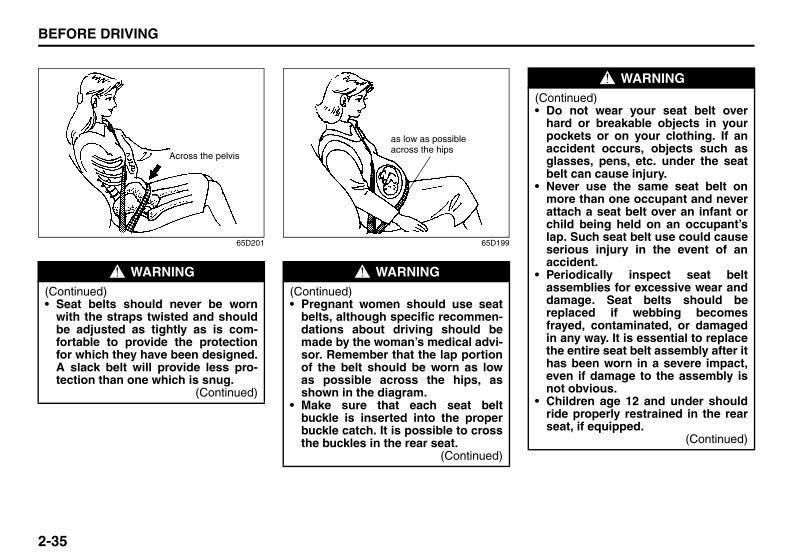
65D201 65D199
WARNING(Continued)• Seat belts should never be worn
with the straps twisted and shouldbe adjusted as tightly as is com-fortable to provide the protectionfor which they have been designed.A slack belt will provide less pro-tection than one which is snug.
(Continued)
Across the pelvis
WARNING(Continued)• Pregnant women should use seat
belts, although specific recommen-dations about driving should bemade by the woman’s medical advi-sor. Remember that the lap portionof the belt should be worn as lowas possible across the hips, asshown in the diagram.
• Make sure that each seat beltbuckle is inserted into the properbuckle catch. It is possible to crossthe buckles in the rear seat.
(Continued)
as low as possible across the hips
WARNING(Continued)• Do not wear your seat belt over
hard or breakable objects in yourpockets or on your clothing. If anaccident occurs, objects such asglasses, pens, etc. under the seatbelt can cause injury.
• Never use the same seat belt onmore than one occupant and neverattach a seat belt over an infant orchild being held on an occupant’slap. Such seat belt use could causeserious injury in the event of anaccident.
• Periodically inspect seat beltassemblies for excessive wear anddamage. Seat belts should bereplaced if webbing becomesfrayed, contaminated, or damagedin any way. It is essential to replacethe entire seat belt assembly after ithas been worn in a severe impact,even if damage to the assembly isnot obvious.
• Children age 12 and under shouldride properly restrained in the rearseat, if equipped.
(Continued)
Supplemental Restraint System (advanced air bags): 3, 9, 12

2-36
BEFORE DRIVING
57L20-03E
Lap-Shoulder BeltEmergency Locking Retractor (ELR)The seat belt has an emergency lockingretractor (ELR), which is designed to lockthe seat belt only during a sudden stop orimpact. It also may lock if you pull the beltacross your body very quickly. If this hap-pens, let the belt go back to unlock it, thenpull the belt across your body more slowly.
Automatic Locking Retractor (ALR)The front passenger’s seat belt and therear seat belts have emergency lockingretractors (ELRs) that can be temporarilyconverted to function as automatic lockingretractors (ALRs). The ALR mode shouldbe used if you need to secure a childrestraint system in the seat. Refer to the“Child Restraint Systems” section fordetails.
Safety reminder
60A038
60A040
WARNING(Continued)• Infants and small children should
never be transported unless theyare properly restrained. Restraintsystems for infants and small chil-dren can be purchased commer-cially and should be used. Makesure that the system you purchasemeets Federal Motor Vehicle SafetyStandards. Read and follow all thedirections provided by the manu-facturer.
• Avoid contamination of seat beltwebbing by polishes, oils, chemi-cals and particularly battery acid.Cleaning may safely be carried outusing mild soap and water.
• For children, if the shoulder beltirritates the neck or face, move thechild closer to the center of thevehicle.
• All seatbacks should always be inan upright position when driving,or seat belt effectiveness may bereduced. Seat belts are designed tooffer maximum protection whenseatbacks are in the upright posi-tion.
Sit up straight and fully back
Low on hips
Low on hips
Supplemental Restraint System (advanced air bags): 3, 9, 12

2-37
BEFORE DRIVING
57L20-03E
To reduce the risk of sliding under the beltduring a collision, position the lap portionof the belt across your lap as low on yourhips as possible and adjust it to a snug fitby pulling the shoulder portion of the beltupward through the latch plate. The lengthof the diagonal shoulder strap adjusts itselfto allow freedom of movement.
All Seat Belts Except Rear Center
60A036
To fasten the seat belt, sit up straight andwell back in the seat, pull the latch plateattached to the seat belt across your bodyand press it into the buckle until you hear a“click”.
60A039
To unfasten the belt, push the red“PRESS” button on the buckle and allowthe belt to retract.
Supplemental Restraint System (advanced air bags): 3, 9, 12

2-38
BEFORE DRIVING
57L20-03E
Rear Center Seat Belt
57L21183
The rear center seat belt is a “Lap-shoul-der belt” with a buckle, a latch plate and adetachable connector. The buckle ismarked as “CENTER” for distinction fromthe rear right seat belt buckle. The rearcenter seat belt buckle and the connectorare designed so as not to allow a wronglatch plate to be inserted.
When the rear seatback is in upright posi-tion, keep the detachable connectorlatched. Only when the rear seatback willbe folded down, unlatch the detachableconnector. To latch and unlatch the con-nector, see “Unlatching and LatchingDetachable Connector” later in this sec-tion.
Fastening
57L21184
Before fastening the rear center belt, makesure the detachable connector (1) issecurely latched and the webbing is nottwisted.
To fasten the belt, sit up straight and wellback in the seat, pull the latch plate (A)across your body and press it into thebuckle (B) until you hear a “click”.
Unfastening
57L21185
To unfasten the belt, push the red“PRESS” button on the buckle (B) andallow the belt to retract.
(B)
(A)
(1)
(B)
Supplemental Restraint System (advanced air bags): 3, 9, 12

2-39
BEFORE DRIVING
57L20-03E
57L30107
57L21108
Unlatching and Latching Detachable ConnectorUnlatching
57L21186
To unlatch the connector:1) Insert the key into the slot on the con-
nector (D) and allow the belt to retract.2) Once the belt has completely retracted,
stow the belt in the holder. Refer to“Stowing Rear Center Lap-ShoulderBelt” for details later in this section.
WARNINGTo minimize risk of severe injury ordeath in the event of a crash, alwayswear seat belt with both latches buck-led.
CAUTIONWhen the rear seatback is folded for-ward, be sure to unlatch the connec-tor of rear center belt. Otherwise, theseat belt webbing can be damaged.
(D)
Supplemental Restraint System (advanced air bags): 3, 9, 12

2-40
BEFORE DRIVING
57L20-03E
LatchingTo latch the connector:1) Pull the belt out from the holder.
57L21187
2) Insert the connector latch plate (C) intothe connector (D) so as to align the tri-angle marks until you hear a “click”.
Stowing Rear Center Lap-Shoulder BeltBe sure to stow the belt after the belt isretracted completely.
57L21188
To stow the belt, insert the latch plate (A)into the slot of the holder. To pull the beltout, simply pull the latch plate.
Seat Belt ReminderDriver’s seat belt reminder light
57L21042
Front passenger’s seat belt reminderlight (if equipped)
57L21043
WARNINGMake sure the detachable connectoris securely latched and the webbingis not twisted.
(C)
(D)
WARNINGStow the belt end properly, or the beltend may hit passengers in case ofvehicle bumps.
(A)
EXAMPLE
Supplemental Restraint System (advanced air bags): 3, 9, 12

2-41
BEFORE DRIVING
57L20-03E
When the driver and front passenger don’tbuckle their seat belts, the driver’s seat beltreminder light in the instrument cluster andthe front passenger’s seat belt reminderlight in the information display will come onand a buzzer will sound as a reminder tothe driver and front passenger to buckletheir seat belts.
The seat belt reminder functions as shownin the figure below. There are some differ-ences between the driver’s seat beltreminder and the front passenger’s seatbelt reminder. For more details, refer to thefollowing explanation.
WARNINGIt is absolutely essential that thedriver and passengers wear their seatbelts at all times. Persons who arenot wearing seat belts have a muchgreater risk of injury if an accidentoccurs. Make a regular habit of buck-ling your seat belt before starting theengine.
Supplemental Restraint System (advanced air bags): 3, 9, 12

2-42
BEFORE DRIVING
57L20-03E
Flow chart
57L21044
Reminder 1 – 3For each reminder 1 – 3, the reminder light comes on for about 20 seconds, then blinks forabout 55 seconds. When the reminder light first comes on, a buzzer sounds intermittentlyfor about 6 seconds.
Engine Switch “ON”
Seat belt isbuckled
30 sec.
Vehicle speed:increase to 8 km/h
Seat belt isunbuckled
Vehicle speed:below 8 km/h
Vehicle speed:over 8 km/h
Reminder 3
3 min.
No reminderSeat belt isunbuckled
Vehicle speed:below 8 km/h
Vehicle speed:over 8 km/h
No reminder
Reminder 2
Reminder 1
Driver’s seat belt reminderIf the driver’s seat belt remains unbuckledafter changing the ignition mode to “ON” bypressing the engine switch, the driver’sseat belt reminder works as follows:1) The driver’s seat belt reminder light will
come on for about 20 seconds whenthe ignition mode is changed to “ON”by pressing the engine switch, theengine switch then will blink for about55 seconds. When the light comes on,a buzzer will also sound intermittentlyfor about 6 seconds (Reminder 1).
2) If the vehicle is driven (vehicle speed >8 km/h), Reminder 2 will operate about30 seconds after Reminder 1 has fin-ished. If the vehicle is not driven (vehiclespeed < 8 km/h), Reminder 2 will oper-ate when driving starts (vehicle speed >8 km/h).
3) Reminder 3 will operate about 3 min-utes after Reminder 2 has finished.
4) Even if the driver’s seat belt remainsunbuckled after Reminder 3, there willbe no further reminders.
If the driver has buckled his or her seat beltand later unbuckles the seat belt, thereminder system will be activated fromReminder 1 or Reminder 2 according tothe vehicle speed. (Refer to the flow chart.)
The driver’s seat belt reminder will be auto-matically canceled when the driver’s seatbelt is buckled or the ignition mode is

2-43
BEFORE DRIVING
57L20-03E
changed to “LOCK” (OFF) by pressing theengine switch.
Front passenger’s seat belt reminder (ifequipped)The front passenger’s seat belt reminderwill activate only when there is a passen-ger sitting in the front seat. In some situa-tions, however, such as when you placeheavy objects in the front seat, the seatbelt reminder can be activated as if therewere a passenger present. The front pas-senger’s seat belt reminder works in thesame manner as the driver’s seat beltreminder, except that it is not activateduntil 10 seconds after the ignition mode ischanged to “ON” by pressing the engineswitch.
Shoulder Anchor Height Adjuster
57L21045
Adjust the shoulder anchor height so thatthe shoulder belt rides on the center of theoutside shoulder. To upward, slide theanchor up. To downward, slide the anchordown while down the lock lever. Afteradjustment, make sure that the anchor issecurely locked.
Seat Belt Inspection
65D209S
Periodically inspect the seat belts to makesure they work properly and are not dam-aged. Check the webbing, buckles, latchplates, retractors, anchorages and guideloops. Replace any seat belts which do notwork properly or are damaged.
WARNINGBe sure that the shoulder belt is posi-tioned on the center of the outsideshoulder. The belt should be awayfrom your face and neck, but not fall-ing off your shoulder. Misadjustmentof the belt could reduce the effective-ness of the safety belt in a crash.
EXAMPLE EXAMPLE

2-44
BEFORE DRIVING
57L20-03E
Child Restraint Systems
60G332
Infant restraint - rear seat only
65D202
Infant restraint - rear seat only
80JC007
Booster seat
80JC008
WARNINGBe sure to inspect all seat beltassemblies after any collision. Anyseat belt assembly which was in useduring a collision (other than a veryminor one) should be replaced, evenif damage to the assembly is notobvious. Any seat belt assemblywhich was not in use during a colli-sion should be replaced if it does notfunction properly, it is damaged inany way or the seat belt pretension-ers were activated.
EXAMPLE
EXAMPLE
EXAMPLE

2-45
BEFORE DRIVING
57L20-03E
SUZUKI highly recommends that you usea child restraint system to restrain infantsand small children. Many different types ofchild restraint systems are available; makesure that the restraint system you selectmeets Federal Motor Vehicle Safety Stan-dards.
All child restraint systems are designed tobe secured in vehicle seats by either seatbelts (lap belts or the lap portion of lap-shoulder belts) or by special rigid loweranchor bars built into the seats. Wheneverpossible, SUZUKI recommends that childrestraint systems be installed on the rearseat. According to accident statistics, chil-dren are safer when properly restrained inrear seating positions than in front seatingpositions.
If you must use a front-facing child restraintin the front passenger’s seat, be sure tomove the front passenger’s seat as farback as possible.
65D607 65D608
65D609
WARNINGDo not install a rear-facing childrestraint in the front passenger’sseat. If the passenger’s air baginflates, a child in a rear-facing childrestraint could be killed or seriouslyinjured. The back of a rear-facingchild restraint would be too close tothe inflating air bag.

2-46
BEFORE DRIVING
57L20-03E
Installation with Lap-Shoulder Seat Belts (child restraint with no top strap)A-ELR type belt
83E031
Install your child restraint system accord-ing to the instructions provided by the childrestraint system manufacturer. If you installthe child restraint system in the front seat,be sure to slide the seat to the rearmostposition. After making sure that the seatbelt is securely latched:
57L31032
1) If you install the child restraint system inthe rear right or left seat, remove thehead restraint (1) or raise the headrestraint upright and make it lock at thehighest position.
WARNINGChildren could be endangered in acrash if their child restraints are notproperly secured in the vehicle.When installing a child restraint sys-tem, be sure to follow the instruc-tions below. Be sure to secure thechild in the restraint system accord-ing to the manufacturer’s instruc-tions.
WARNINGIn an accident or sudden stop, therear seat armrest (if equipped) couldfall forward. If there is a child in arear-facing child restraint in the cen-ter seating position, the falling arm-rest could injure the child. Make surethe armrest is back in the seat andlocked when not in use.
EXAMPLE
(1)

2-47
BEFORE DRIVING
57L20-03E
A-ELR type belt
83E035
2) Pull all of the remaining webbing out ofthe retractor. You will hear a click, whichmeans that the emergency lockingretractor (ELR) has converted to func-tion as an automatic locking retractor(ALR).
A-ELR type belt
83E032
3) Allow the extra webbing to retract, andpull the webbing toward the retractor totake up any slack. Make sure that thelap portion of the belt is tight around thechild restraint system and the shoulderportion of the belt is positioned so that itcannot interfere with the child’s head orneck.
A-ELR type belt
83E036
4) Make sure that the retractor has con-verted to the ALR mode by trying to pullwebbing out of the retractor. If theretractor is in the ALR mode, the beltwill be locked.
EXAMPLE EXAMPLE
WARNINGIf the retractor is not in the ALRmode, the child restraint system canmove or tip over when your vehicleturns or stops abruptly.
EXAMPLE

2-48
BEFORE DRIVING
57L20-03E
A-ELR type belt
65D234
A-ELR type belt
65D235
5) Try moving the child restraint system inall directions, to make sure it is securelyinstalled. If you need to tighten the belt,pull more webbing toward the retractor.
To revert from ALR to ELR
65D267
When you unbuckle the seat belt and allowit to retract to a certain length, the retractorwill automatically revert back to the normalELR mode.
WARNINGBefore installing a child restraint inthe rear center seat, follow thesesteps for secure installation:• Make sure the detachable connec-
tor is securely latched and the web-bing is not twisted.
• Make sure the seat belt is passedthrough the seat belt guide.
EXAMPLE
Move to check
EXAMPLE
Pull to tighten
EXAMPLE

2-49
BEFORE DRIVING
57L20-03E
Installation with the LATCH System
65D337
57L21046
Your vehicle is equipped with loweranchors for securing up to one or two stan-dard LATCH-type child restraint(s) in therear seats. (LATCH stands for LowerAnchors and Tethers for Children.) The anchors are located where the rear ofthe seat cushion meets the bottom of theseatback.
57L21047
The covers marked with the child restraintsymbol as shown in the illustration indicatethe presence of lower anchors. Removethe covers before installing the childrestraint system. Cover the lower anchorswhen not in use.
NOTE:Stow the removed covers in the glove boxor other appropriate stowage so they willnot inconvenience the occupants.
Install the LATCH-type child restraint sys-tem according to the instructions providedby the child restraint system manufacturer.After installing, try moving the childrestraint system in all directions, especiallyforward to make sure the flexible straps orrigid connecting bars are securely latchedto the anchors.
Rigid lower connecting bar type
Flexible lower connecting strap type
EXAMPLE EXAMPLE

2-50
BEFORE DRIVING
57L20-03E
NOTE:Although there are three rear seating posi-tions, you cannot install three LATCH typechild restraints in the rear seats. You caninstall one or two LATCH restraint(s). Besure to install the LATCH type childrestraint(s) in the outboard seating posi-tions.
If your LATCH restraint has flexible lowerconnecting straps, these general instruc-tions apply:1) If possible, fold the seatback rearward
for easier installation.
73K017
2) Place the child restraint in the rear seat,feeding the strap hooks through theslots in the seat cushion or the slots inthe seatback bottom.
65D340
3) Snap the strap hooks to the anchors.Take care not to pinch your fingers.
65D341
4) Return the seatback to the normal,upright position. Tighten the lowerstraps as described in the child restraintowner’s manual. Attach the top tetherstrap, if applicable.
EXAMPLE
EXAMPLE EXAMPLE

2-51
BEFORE DRIVING
57L20-03E
65D342
5) Make sure the child restraint is securelyfastened by trying to move the childrestraint system in all directions, espe-cially forward.
If your LATCH restraint has rigid lower con-necting bars, these general instructionsapply:1) If possible, fold the seatback rearward
for easier installation.
78F114
2) Place the child restraint in the rear seat,inserting the connecting bars throughthe slots in the seat cushion or the slotsin the seatback bottom.
54G183
3) Use your hands to carefully align theconnecting bar tips with the anchors.Take care not to pinch your fingers.
WARNINGThe seatback should always besecurely latched in a fairly uprightposition when any type of child seatis installed. An unlatched or reclinedseatback will reduce the intendedeffectiveness of the child restraintsystem.
EXAMPLE
EXAMPLE
EXAMPLE

2-52
BEFORE DRIVING
57L20-03E
54G184
4) Push the child restraint toward theanchors so that the connecting bar tipsare partially hooked to the anchors.Use your hands to confirm the position.
54G185
5) Grasp the front of the child restraint andpush the child restraint forcefully tolatch the connecting bars. Make surethey are securely latched by trying tomove the child restraint system in alldirections, especially forward.
6) Return the seatback if folded. Attachthe top tether strap, if applicable.
Installation of Child Restraint with Top Strap
57L21048
Some child restraint systems require theuse of a top strap. Top strap anchor brack-ets are provided in your vehicle at the loca-tions shown in the illustrations. Install thechild restraint system as follows:1) Secure the child restraint on the rear
seat using the procedure describedabove for securing a restraint systemthat does not require a top strap.
2) Open the cover that is marked with theanchor bracket symbol to access theanchor bracket. Close the cover whennot using the anchor bracket.
3) Hook the top strap to the anchorbracket and tighten the top strapaccording to the instructions providedby the child restraint system manufac-turer. Be sure to attach the top strap tothe corresponding anchor located
EXAMPLE
WARNINGThe seatback should always besecurely latched in a fairly uprightposition when any type of child seatis installed. An unlatched or reclinedseatback will reduce the intendedeffectiveness of the child restraintsystem.
EXAMPLE

2-53
BEFORE DRIVING
57L20-03E
directly behind the child restraint. Donot attach the top strap to the luggagerestraint loops (if equipped).
57L21049
4) When routing the top strap, be sure topass the top strap as shown in the illus-tration. (Refer to “Adjustable HeadRestraints” section for details on how toraise or lower the head restraint.)
5) Make sure that cargo does not interferewith routing of the top strap.
Seat Belt Extender
65D613
(1) Center of body(2) Less than 152 mm (6 inches)(3) Open end of extender buckle
If a seat belt cannot be fastened securelybecause it is not long enough, see anauthorized SUZUKI dealer for a seat beltextender. Seat belt extenders are availablefor each seating position except for therear center position. After inspecting therelationship between the seat belt length,the occupant’s body size, and the seatadjustment (the driver’s seat should alwaysbe adjusted as far back as possible whilestill maintaining control of the vehicle, andother adjustable seats should be adjustedas far back as possible), your dealer canselect the appropriate seat belt extender.
WARNINGDo not attach the child restraint topstrap to the luggage restraint loops(if equipped). Incorrectly attached topstrap will reduce the intended effec-tiveness of the child restraint system.
Type 2
Type 1

2-54
BEFORE DRIVING
57L20-03E
• A seat belt extender should only be usedfor the person, vehicle and seating loca-tion it was provided for.
• When using the extender, ensure thatboth ends are latched securely. Do notuse the extender if the open end of theextender’s buckle is within 152 mm (6inches) of the center of the occupant’sbody (See diagram). Use of the extenderwhen the buckle is too close to the cen-ter of the body could increase the risk ofabdominal injury in the event of an acci-dent, and could cause the shoulder beltto be positioned incorrectly.
• Make sure to use the correct buckle cor-responding to your seating position.
• Seat belt extenders are not intended foruse by pregnant women, and shouldonly be used upon approval by theirmedical advisors.
• Remove and stow the extender when itis not being used.
Seat Belt Pretensioner System (for front seat belt only)
57L21125
Your vehicle is equipped with a seat beltpretensioner system at the front seatingpositions. You can use the pretensionerseat belts in the same manner as ordinaryseat belts.
The seat belt pretensioner system workswith the SUPPLEMENTAL RESTRAINTSYSTEM (advanced air bags). The crashsensors and the electronic controller of theair bag system also control the seat beltpretensioners. The pretensioners are trig-gered only when there is a frontal or sidecrash severe enough to trigger the air bagsand the seat belts are fastened. If the seatbelts are not fastened, the respective pre-tensioner system will not be activated. Forprecautions and general informationincluding servicing the pretensioner sys-tem, refer to the “Supplemental RestraintSystem (air bags)” section in addition tothis “Seat Belt Pretensioner System” sec-tion, and follow all those precautions.
WARNINGFailure to follow these instructionsmay increase the risk of injury in acrash.• Only use an extender for the per-
son, vehicle and seating position itwas provided for.
• Do not use if open end ofextender’s buckle is within 152 mm(6 inches) of center of occupant’sbody (See diagram).
• Remove and stow the extenderwhen it is not being used.
EXAMPLE
WARNINGThis section of the owner’s manualdescribes your SUZUKI’s SEAT BELTPRETENSIONER SYSTEM. Pleaseread and follow ALL these instruc-tions carefully to minimize your riskof severe injury or death.

2-55
BEFORE DRIVING
57L20-03E
The front seat belt retractors and lap beltanchorages are each provided with a pre-tensioner. The pretensioner tightens theseat belt so the belt fits the occupant’sbody more snugly in the event of a frontalor side crash. The retractors will remainlocked after the pretensioners are acti-vated. Upon activation, some noise willoccur and some smoke may be released.These conditions are not harmful and donot indicate a fire in the vehicle.
The driver and all passengers must beproperly restrained by wearing seat beltsat all times, whether or not a pretensioneris equipped at their seating position, tohelp minimize the risk of severe injury ordeath in the event of a crash.
Sit fully back in the seat; sit up straight; donot lean forward or sideways. Adjust thebelt so the lap portion of the belt is wornlow across the pelvis, not across the waist.Please refer to the “Seat Adjustment” sec-tion and the instructions and precautionsabout the seat belts in this “Seat Belts andChild Restraint Systems” section for detailson proper seat and seat belt adjustments.Please note that the pretensioners alongwith the air bags will activate only in severefrontal or side collisions. They are notdesigned to activate in rear impacts, roll-overs or minor frontal collisions. The pre-tensioners can be activated only once. Ifthe pretensioners are activated (that is, ifthe air bags are activated), have the pre-
tensioner system serviced by an autho-rized SUZUKI dealer as soon as possible.
If the AIR BAG light on the instrument clus-ter does not blink or come on briefly whenthe ignition mode is changed to “ON” bypressing the engine switch, stays on formore than 10 seconds, or comes on whiledriving, the pretensioner system or the airbag system may not work properly. Haveboth systems inspected by an authorizedSUZUKI dealer as soon as possible.Service on or around the pretensioner sys-tem components or wiring must be per-formed only by an authorized SUZUKIdealer who is specially trained. Improperservice could result in unintended activa-tion of pretensioners or could render thepretensioner inoperative. Either of thesetwo conditions may result in personalinjury.
To prevent damage or unintended activa-tion of the pretensioners, be sure the bat-tery is disconnected and the engine switchhas been in the “LOCK” (OFF) mode for atleast 90 seconds before performing anyelectrical service work on your SUZUKI.Do not touch pretensioner system compo-nents or wiring. The wires are wrappedwith yellow tape or yellow tubing, and thecouplers are yellow. When scrapping yourSUZUKI, ask an authorized SUZUKIdealer, body repair shop or scrap yard forassistance.
Supplemental Restraint System (air bags)
54G022
Your vehicle has advanced front air bagsand front side air bags for the driver andright front passenger. Your vehicle also hasside curtain air bags and rear side airbags.
WARNINGThis section of the owner’s manualdescribes the protection provided byyour SUZUKI’s SUPPLEMENTALRESTRAINT SYSTEM (air bags).Please read and follow ALL theseinstructions carefully to minimizeyour risk of severe injury or death inthe event of a collision.
EXAMPLE

2-56
BEFORE DRIVING
57L20-03E
57L21050
1
7
2 10
9
3
4
12
12
13
4
39
11
8
8 116
5
15
EXAMPLE
57L21051
Your vehicle is equipped with a Supple-mental Restraint System consisting of thefollowing components in addition to a lap-shoulder belt at each front seating position.
1. Driver’s front air bag2. Front passenger’s front air bag 3. Seat belt pretensioners4. Lap outer pretensioners5. Air bag controller6. Occupant classification module7. “PASS AIR BAG OFF” indicator8. Forward crash sensors9. Front side air bags10.Side curtain air bags11.Side crash sensors12.Rear side air bags13.Rear side crash sensors14.Front passenger’s sensor mat15.Seat belt buckle sensors
14

2-57
BEFORE DRIVING
57L20-03E
63J030
If the AIR BAG light on the instrument clus-ter does not blink or come on when theignition mode is first changed to “ON” bypressing the engine switch, or the AIRBAG light stays on, or comes on while driv-ing, the air bag system (or the seat beltpretensioner system) may not work prop-erly. Have the air bag system inspected byan authorized SUZUKI dealer as soon aspossible.
Front Air Bags
80JS026
57L21115
57L21116
The driver’s front air bag is located behindthe center pad of the steering wheel andthe front passenger’s front air bag islocated behind the passenger’s side of thedashboard. The words “SRS AIRBAG” aremolded into the air bag covers to identifythe location of the air bags.
EXAMPLE
EXAMPLE
EXAMPLE

2-58
BEFORE DRIVING
57L20-03E
Frontal collision range
60G032
Front air bags are designed to inflate onlyin severe frontal collisions.
Front air bags will not inflate
65D236
Front air bags will probably not inflate
65D237
Front air bags are not designed to inflate inrear impacts, side impacts, rollovers orminor frontal collisions, since they wouldoffer no protection in those types of acci-dents. Remember, since air bags deployonly one time during an accident, seatbelts are needed to restrain occupantsfrom further movements during the acci-dent.
Therefore, an air bag is NOT a substitutefor seat belts. To maximize your protection,ALWAYS WEAR YOUR SEAT BELTS. Beaware that no system can prevent all pos-sible injuries that may occur in an accident.
Your vehicle has “dual stage” front airbags, which adjust the air bag inflationforce according to crash severity. Also,your vehicle has a front passenger sensingsystem, which turns off the front passen-ger’s front air bag and seat belt preten-sioner under certain conditions.
WARNINGAn air bag supplements, or adds to,the crash protection offered by seatbelts. The driver and all passengersmust be properly restrained by wear-ing seat belts at all times, whether ornot air bags are mounted at theirseating position, to minimize the riskof severe injury or death in the eventof a crash.

2-59
BEFORE DRIVING
57L20-03E
Front Side Air Bags, Rear Side Air Bags and Side Curtain Air Bags
57L21052
57L21053
Front side air bags are located in the partof the front seatbacks closest to the doors.The words “SRS AIRBAG” are indicated onthe tag to identify the location of the frontside air bags.
57L21054
The rear side air bags are stowed in thecovers at both door-side ends of the rearseatback. The words “SRS AIRBAG” aremolded into each of the seatback ends.
EXAMPLE
EXAMPLE

2-60
BEFORE DRIVING
57L20-03E
80JM146
Side curtain air bags are located in the rooflining. The words “SRS AIRBAG” aremolded into the pillar to identify the loca-tion of the side curtain air bags.
Side collision range
80JM032
Front side air bags, rear side air bags andside curtain air bags are designed to inflateonly in severe side impact collisions.
Front side air bags, rear side air bagsand side curtain air bags will not inflate
54G027
EXAMPLE

2-61
BEFORE DRIVING
57L20-03E
Front side air bags, rear side air bagsand side curtain air bags will probablynot inflate
57L21126
Front side air bags, rear side air bags andside curtain air bags are not designed toinflate in frontal or rear collisions, rolloversor minor side collisions, since they wouldoffer no protection in those types of acci-dents. Only the front side air bag, rear sideair bag and side curtain air bag on the sideof the vehicle that is struck will inflate.However, in a frontal angle collision, theright and left front side air bags, rear sideair bags and side curtain airbags mayinflate. Remember, since an air bagdeploys only one time during an accident,seat belts are needed to restrain occu-pants from further movements during theaccident.
Therefore, an air bag is NOT a substitutefor seat belts. To maximize your protection,
ALWAYS WEAR YOUR SEAT BELTS. Beaware that no system can prevent all pos-sible injuries that may occur in an accident.
Front Passenger’s Seat Belt Buckle SensorThe front passenger’s seat belt buckle isequipped with a sensor to monitor whetheror not the front passenger’s seat belt is fas-tened.
WARNINGAn air bag supplements, or adds to,the crash protection offered by seatbelts. The driver and all passengersmust be properly restrained by wear-ing seat belts at all times, whether ornot air bags are mounted at theirseating position, to minimize the riskof severe injury or death in the eventof a crash.
WARNINGIf the AIR BAG light in the instrumentcluster ever comes on and stays on,it means that something may bewrong with the air bag system. If thisever happens, have the vehicle ser-viced immediately, because the airbags may not offer the protection forwhich they were designed.
WARNINGWhen the buckle sensor has a prob-lem, the AIR BAG light on the instru-ment cluster will turn on. If thishappens, deployment of the frontpassenger’s air bag will not includeconsideration of whether the frontpassenger’s seat belt is fastened ornot. Have the air bag systeminspected by an authorized SUZUKIdealer as soon as possible.

2-62
BEFORE DRIVING
57L20-03E
Front Passenger Sensing SystemThe front passenger sensing system willturn off the front passenger’s front air bagand seat belt pretensioner under certainconditions. This system works using a sen-sor mat that is part of the front passenger’sseat. The front passenger sensing systemis designed to detect whether an occupantis present in the seat and, if an occupant ispresent, to determine whether the frontpassenger’s front air bag and seat belt pre-tensioner should be enabled or disabled(turned off).
NOTE:The front passenger’s side air bag and theside curtain air bag are not controlled bythe front passenger sensing system.
57L21055
When you press the engine switch tochange the ignition mode to “ON”, the“PASS AIR BAG OFF” indicator comes onfor several seconds to let you know thesystem is working. When the front passen-ger sensing system has turned off the frontpassenger’s front air bag including the seatbelt pretensioner, the “PASS AIR BAGOFF” indicator will come on and stay on toremind you that the front passenger’s frontair bag is off.
The front passenger sensing system usesfront seat pressure measurements andpressure locations to determine whether toactivate or deactivate the front passenger’sfront air bag. The front passenger sensingsystem may or may not turn off the front airbag, depending on the front passenger’sseating posture and body build. The airbag should be turned off in the followingsituations:• There is no occupant in the front pas-
senger seat.• The occupant of the front passenger
seat lifts his or her weight off of the seatfor a period of time.
• The occupant of the front passengerseat is an infant or small child in a childrestraint system or a small child in abooster seat.
• A smaller person, such as a child whohas outgrown child restraints or a verysmall adolescent is seated in the frontpassenger seat.
NOTE:If the front passenger seat is unoccupied,the “PASS AIR BAG OFF” indicator will notcome on but the front passenger’s front airbag will not deploy and the seat belt pre-tensioner will not operate.
If you have secured a child in the front pas-senger seat in a forward-facing childrestraint system or booster seat and the“PASS AIR BAG OFF” indicator light is noton, turn the vehicle off, remove the childrestraint or booster seat from the vehicleand reinstall it following the child restraintor booster seat manufacturer’s directions.Also refer to “Seat Belts and ChildRestraint Systems” in this section. If, afterreinstalling the child restraint and restart-ing the vehicle, the “PASS AIR BAG OFF”indicator is still not lit, check to make surethat the vehicle’s seatback is not pressingthe child restraint into the seat cushion. Ifthis happens, slightly recline the vehicle’sseatback and adjust the seat cushion ifpossible. Also make sure the child restraintis not trapped under the vehicle headrestraint. If this happens, adjust the headrestraint. If the “PASS AIR BAG OFF” indi-cator is still not on, secure the child in thechild restraint or booster seat in a rear seatposition in the vehicle and check with yourdealer.
PASSENGERAIRBAG OFF
PASSENGERAIRBAG OFF

2-63
BEFORE DRIVING
57L20-03E
65D607
According to accident statistics, childrenare safer when properly restrained in rearseating positions than in front seating posi-tions. Whenever possible, SUZUKI recom-mends you install child restraints in therear seat.
The front passenger sensing system isdesigned to enable the front passenger’sfront air bag when the system senses aproperly-seated adult in the front passen-ger’s seat. When the passenger sensingsystem has allowed the air bag to beenabled, the “PASS AIR BAG OFF” indica-tor will remain off to remind you that the airbag is active.
If a person of adult size is sitting in thefront passenger’s seat and the “PASS AIRBAG OFF” indicator comes on, it could bebecause that person isn’t sitting properly inthe seat. If this happens, unfasten the seatbelts, sit upright in the center of the seatwith the seatback nearly vertical and yourlegs outstretched, and refasten the seatbelt.
52D258
When seated as shown in the above illus-tration, the front passenger sensing sys-tem senses a properly-seated occupantand enables the air bag.
When using a seat belt extender, follow theinstructions in the “Seat Belt Extender”section.
WARNINGDo not install a rear-facing childrestraint in the front passenger’sseat. If the passenger’s front air baginflates, a child in a rear-facing childrestraint could be seriously injured.The back of a rear-facing childrestraint would be too close to theinflating air bag.
WARNINGDo not place any heavy objects onthe front passenger’s seat. The pres-sure sensors in the sensor mat couldbe damaged and the front passengersensing system may not work prop-erly.

2-64
BEFORE DRIVING
57L20-03E
How the System WorksIn a frontal collision, the crash sensors willdetect rapid deceleration and send a signalto the controller. If the controller judgesthat the deceleration represents a severefrontal crash, the controller will trigger theinflators. The controller also judges:• Whether the front air bags should deploy
at reduced power or at full power accord-ing to crash severity.
• Whether the air bags should deploy atreduced power or at full power accordingto crash severity.
• Whether the front passenger’s front airbag should deploy or not based on clas-sification of the occupant of the frontpassenger’s seat.
Since your vehicle is equipped with frontside air bags, rear side air bags and sidecurtain air bags, crash sensors will detecta side collision, and if the controller judgesthat the side collision is severe enough, itwill trigger the front side air bag, rear sideair bags and side curtain air bag inflators.
The inflators inflate the appropriate airbags with nitrogen or argon gas. Theinflated air bags provide a cushion for yourhead (front air bags and side curtain airbags only) and upper body. The air baginflates and deflates so quickly that youmay not even realize that it has activated.The air bag will neither hinder your viewnor make it harder to exit the vehicle.
WARNINGThe front passenger sensing systemmay not work properly in the follow-ing situations:• The occupant is sitting near the
dashboard or is not sitting in theproper position.
• Objects placed under the seat arepushing up on the seat cushion.
WARNINGIf the “PASS AIR BAG OFF” indicatoron the instrument panel turns oneven though there is no occupant oran adult occupant in the front pas-senger’s seat, it means that some-thing may be wrong with thepassenger sensing system. Have thesystem inspected by an authorizedSUZUKI dealer as soon as possible.
WARNING• Do not spill any liquids on the seat.
Liquids can damage the sensorsunder the front seat.
• Have the front passenger’s sensormat inspected by your dealer aftera collision.
• Do not replace the front seats. Ifyou replace them, the air bags andfront passenger sensing systemmay not work properly.
• Do not use a seat cover. If you usea seat cover, the front passengersensing system may not work prop-erly.

2-65
BEFORE DRIVING
57L20-03E
Air bags must inflate quickly and forcefullyin order to reduce the chance of serious orfatal injuries. However, an unavoidableconsequence of the quick inflation is thatthe air bag may irritate bare skin, such asthe facial area against a front air bag. Also,upon inflation, a loud noise will occur andsome powder and smoke will be released.These conditions are not harmful and donot indicate a fire in the car. Be aware,however, that some air bag componentsmay be hot for a while after inflation.
A seat belt helps keep you in the properposition for maximum protection when anair bag inflates. Adjust your seat as farback as possible while still maintainingcontrol of the vehicle. Sit fully back in yourseat; sit up straight; do not lean over thesteering wheel or dashboard. Front occu-pants should not lean on or sleep againstthe door. Please refer to the “Seat Adjust-ment” section and the “Seat Belts andChild Restraint Systems” section in the“BEFORE DRIVING” section for details onproper seat and seat belt adjustments.
65D610
54G582
WARNING• The driver should not lean over the
steering wheel. The front passen-ger should not rest his or her bodyagainst the dashboard, or other-wise get too close to the dash-board. For vehicles with side airbags, rear side air bags and sidecurtain air bags, occupants shouldnot lean on or sleep against thedoor. In these situations, the out-of-position occupant would be tooclose to an inflating air bag, andmay suffer severe injury.
• Do not attach any objects to, orplace any objects over, the steeringwheel or dashboard. Do not placeany objects between the air bagand the driver or front passenger.These objects may interfere with airbag operation or may be propelledby the air bag in the event of acrash. Either of these conditionsmay cause severe injury.
• For vehicles with front side airbags, do not place seat covers onthe front seats, because seat cov-ers could restrict the air bag’s infla-tion. Also, do not place any cupholders or other objects on thedoor, as these objects could bepropelled by the air bag in the eventof a crash. Either of these condi-tions may cause severe injury.

2-66
BEFORE DRIVING
57L20-03E
Note that even though your vehicle may bemoderately damaged in a collision, the col-lision may not have been severe enough totrigger the front, side, rear side, or sidecurtain air bags to inflate. If your car sus-tains ANY front-end or side damage, havethe air bag system inspected by an autho-rized SUZUKI dealer to ensure it is inproper working order.
Your vehicle is equipped with a diagnosticmodule which records information aboutthe air bag system if the air bags deploy ina crash. The module records informationabout overall system status, which sensorsactivated the deployment, and whether thefront seat belts were in use.
Servicing the Air Bag SystemIf the air bags inflate, have the air bags andrelated components replaced by an autho-rized SUZUKI dealer as soon as possible.
If your vehicle ever gets in deep water andthe driver’s floor is submerged, the air bagcontroller could be damaged. If this hap-pens, have the air bag system inspectedby the SUZUKI dealer as soon as possible.
Special procedures are required for servic-ing or replacing an air bag. For that reason,only an authorized SUZUKI dealer shouldbe allowed to service or replace your airbags. Please remind anyone who servicesyour SUZUKI that it has air bags.
Service on or around air bag componentsor wiring must be performed only by anauthorized SUZUKI dealer. Improper ser-vice could result in unintended air bagdeployment or could render the air bagsinoperative. Either of these two conditionsmay result in severe injury.
To prevent damage or unintended inflationof the air bag system, be sure the batteryis disconnected and the engine switch hasbeen in the “LOCK” (OFF) mode for atleast 90 seconds before performing anyelectrical service work on your SUZUKI.Do not touch air bag system componentsor wires. The wires are wrapped with yel-low tape or yellow tubing, and the couplersare yellow for easy identification.
Scrapping a car that has an undeployed airbag can be hazardous. Ask your dealer,body repair shop or scrap yard for helpwith disposal.

2-67
BEFORE DRIVING
57L20-03E
If it is necessary to modify the advancedfront air bag system to accommodate aperson with disabilities, owners in the con-tinental United States can call AmericanSuzuki toll-free at 1-800-934-0934, or writeto:
American Suzuki Motor Corporation Automotive Customer Relations 3251 East Imperial Highway Brea, CA 92821-6795
If you purchased your SUZUKI in Canadaplease contact the Suzuki Canada Cus-tomer Relations Department by telephoneat 1-905-889-2677 extension 2254 or inwriting at:
Suzuki Canada Inc.Customer Relations100 East Beaver Creek RoadRichmond Hill, OnL4B 1J6

2-68
BEFORE DRIVING
57L20-03E
Instrument Cluster1. Speedometer2. Tachometer3. Fuel gauge4. Temperature gauge5. Information display6. Brightness control knob
57L21056
(2) (1)
(3)(6)(5)(4)
EXAMPLE

2-69
BEFORE DRIVING
57L20-03E
Warning and Indicator LightsLow Tire Pressure Warning Light (if equipped)
52D305
As an added safety feature, your vehiclehas been equipped with a tire pressuremonitoring system (TPMS) that uses a lowtire pressure warning light to inform youwhen one or more of your tires is signifi-cantly under-inflated.
When you press the engine switch tochange the ignition mode to “ON”, this lightcomes on briefly so you can check that thelight is working.
When the low tire pressure warning light islit, one or more of your tires is significantlyunder-inflated. You should stop and checkyour tires as soon as possible, and inflatethem to the proper pressure as indicatedon the vehicle’s tire information placard.Driving on a significantly under-inflated tirecauses the tire to overheat and can lead totire failure. Under-inflation also reducesfuel efficiency and tire tread life, and mayaffect the vehicle’s handling and stoppingability. Each tire, including the spare,
should be checked at least once a monthwhen cold and set to the recommendedinflation pressure as specified in the vehi-cle placard and owner’s manual.
The low tire pressure warning light is alsoused to inform you of a TPMS malfunction.When the system detects a malfunction,this light will flash for approximately oneminute and then remain continuously illu-minated. This sequence will be repeatedafter the ignition mode is changed to “ON”by pressing the engine switch as long asthe malfunction exists.
NOTE:The low tire pressure warning light may notcome on immediately if you have a suddenloss of air pressure.
WARNINGIf the low tire pressure warning lightdoes not light for 2 seconds afterpressing the engine switch to changethe ignition mode to “ON”, or comeson and blinks while driving there maybe a problem with the tire pressuremonitoring system. Have your vehi-cle inspected by an authorizedSUZUKI dealer. Even if the light turnsoff after blinking, indicating that mon-itoring system has recovered, makesure to have an authorized SUZUKIdealer check the system.
WARNINGThe load rating of your tires isreduced at lower inflation pressures.If your tires become even moderatelyunder-inflated, the vehicle load mayexceed the load rating of the tires,which can lead to tire failure. The lowtire pressure warning light will notalert you of this condition. The warn-ing light will only come on when oneor more of your tires become signifi-cantly under-inflated. Check andadjust your tire inflation pressure atleast once a month. Refer to “Tires”in the “INSPECTION AND MAINTE-NANCE” section.

2-70
BEFORE DRIVING
57L20-03E
Refer to “Tire Pressure Monitoring System”in the “OPERATING YOUR VEHICLE” sec-tion for additional details on the tire pres-sure monitoring system. Refer to “Tires” inthe “INSPECTION AND MAINTENANCE”section for information on maintainingproper tire pressure.
Brake System Warning Light
65D477
This light comes on briefly when you pressthe engine switch to change the ignitionmode to “ON”. The light also comes onunder the following conditions: 1) when theparking brake is engaged and 2) when thefluid in the brake fluid reservoir falls belowthe specified level. The light should go outafter fully releasing the parking brake, if thefluid level in the brake fluid reservoir isadequate.If this light and the ABS warning light stayon, or come on simultaneously when driv-ing, then there may be something wrongwith both the rear brake proportioningvalve function and anti-lock function of theABS.
If the brake system warning light comes onwhile you are driving the vehicle, it maymean that there is something wrong withthe vehicle’s brake system. If this happens,you should:
WARNINGIf the low tire pressure warning lightcomes on and stays on, reduce yourspeed and avoid abrupt steering andbraking. Stop in a safe place as soonas possible and check your tires.• If you have a flat tire, replace it with
the spare tire. Refer to “JackingInstructions” in the “EMERGENCYSERVICE” section. Refer to“Replacing Tires and/or Wheels”for instructions on how to restorenormal operation of the tire pres-sure monitoring system after youhave had a flat tire.
• If one or more of your tires isunder-inflated, adjust the inflationpressure in all of your tires to therecommended inflation pressure assoon as possible.
Be aware that driving on a signifi-cantly under-inflated tire can causethe tire to overheat and can lead totire failure, and may affect steeringcontrol and brake effectiveness. Thiscould lead to an accident, resulting insevere injury or death.

2-71
BEFORE DRIVING
57L20-03E
1) Pull off the road and stop carefully.
2) Test the brakes by carefully starting andstopping on the shoulder of the road.
3) If you determine that it is safe, drivecautiously at low speed to the nearestdealer for repairs,
or4) Have the vehicle towed to the nearest
dealer for repairs.
NOTE:Because the disc brake system is self-adjusting, the fluid level will drop as thebrake pads become worn.Replenishing the brake fluid reservoir isconsidered normal periodic maintenance.
Anti-Lock Brake System (ABS) Warning Light
65D529
When you press the engine switch tochange the ignition mode to “ON”, the lightcomes on briefly so you can check that thelight is working. If the light stays on, orcomes on when driving, there may besomething wrong with the ABS.
If the ABS light and the brake systemwarning light stay on, or come on simulta-neously when driving, then there may besomething wrong with both the rear brakeproportioning valve function and anti-lockfunction of the ABS.
If one of these happens, have the systeminspected by an authorized SUZUKIdealer. If the ABS becomes inoperative,the brake system will function as an ordi-nary brake system that has no ABS.
For details of the ABS, refer to “Anti-LockBrake System (ABS)” in the “OPERATINGYOUR VEHICLE” section.
ESP® Warning Light
52KM133
ESP® is a registered trademark of DaimlerAG.
This light blinks 5 times per second whenone of the ESP® systems other than ABSis activated. If this light blinks, drive care-fully.
When you press the engine switch tochange the ignition mode to “ON”, the lightcomes on briefly so you can check that thelight is working. If the light stays on, orcomes on when driving and remains on,there may be something wrong with theESP® systems (other than ABS). Youshould have the system inspected by anauthorized SUZUKI dealer.
WARNINGRemember that stopping distancemay be longer, you may have to pushharder on the pedal, and the pedalmay go down farther than normal.
WARNINGIf any of the following conditionsoccur, you should immediately askan SUZUKI dealer to inspect thebrake system.• If the brake system warning light
does not go out after the parkingbrake has been fully released.
• If the brake system warning lightdoes not come on when you pressthe engine switch to change theignition mode to “ON”.
• If the brake system warning lightcomes on at any time during vehi-cle operation.

2-72
BEFORE DRIVING
57L20-03E
NOTE:When you disconnect and re-connect thebattery, ESP® system functions other thanABS will be deactivated. For details on howto reactive the ESP® systems, refer to“ESP® Warning Light” in the “OPERATINGYOUR VEHICLE” section.For details of the ESP® systems, refer to“Electronic Stability Program (ESP®)” inthe “OPERATING YOUR VEHICLE” sec-tion.
“ESP® OFF” Indicator Light
57L30045
When you press the engine switch tochange the ignition mode to “ON”, this lightcomes on briefly so you can check that thelight is working.
When the “ESP® OFF” switch is pushed toturn off the ESP® systems (other thanABS), the “ESP® OFF” light comes on andstays on.
For details of the ESP® systems, refer to“Electronic Stability Program (ESP®)” inthe “OPERATING YOUR VEHICLE” sec-tion.
Oil Pressure Light
50G051
This light comes on when you press theengine switch to change the ignition modeto “ON”, and goes out when the engine isstarted. The light will come on and remainon if there is insufficient oil pressure. If thelight comes on when driving, pull off theroad as soon as you can and stop theengine. Check the oil level and add oil ifnecessary. If there is enough oil, the lubri-cation system should be inspected by anauthorized SUZUKI dealer before you drivethe vehicle again.
WARNINGThe ESP® systems cannot preventaccidents. Always drive carefully.
CAUTION• If you operate the engine with this
light on, severe engine damage canresult.
• Do not rely on the Oil PressureLight to indicate the need to addoil. Be sure to periodically checkthe engine oil level.

2-73
BEFORE DRIVING
57L20-03E
Charging Light
50G052
This light comes on when you press theengine switch to change the ignition modeto “ON”, and goes out when the engine isstarted. The light will come on and remainon if there is something wrong with the bat-tery charging system. If the light comes onwhen the engine is running, the chargingsystem should be inspected immediatelyby an authorized SUZUKI dealer.
Driver’s Seat Belt Reminder Light
60G049
If the driver’s seat belt is unbuckled whenyou press the engine switch to change theignition mode to “ON”, this light will comeon and then blink. When the light comeson, a buzzer will also sound intermittentlyfor about 6 seconds. The reminder willrepeat several times under certain condi-tions until the driver’s seat belt is buckled.After repeating several times, the reminderwill be canceled even if the driver’s seatbelt remains unbuckled.
For details about the seat belt reminder,refer to “Seat Belts and Child RestraintSystems” in this section.
AIR BAG Light
63J030
This light monitors inflators, crash sensors,seat belt pretensioners, the front passen-ger sensing system, and correspondingelectrical circuits.This light blinks or comes on for severalseconds when you press the engine switchto change the ignition mode to “ON”, soyou can check if the light is working. Thelight will come on and stay on if there is aproblem in the air bag system or the seatbelt pretensioner system.
WARNINGIt is absolutely essential that thedriver and passengers wear their seatbelts at all times. Persons who arenot wearing seat belts have a muchgreater risk of injury if an accidentoccurs. Make a regular habit of buck-ling your seat belt before starting theengine.
WARNINGIf the AIR BAG light does not blink orcome on when you press the engineswitch to change the ignition mode to“ON”, or stays on or comes on whendriving, the air bag system or the seatbelt pretensioner system may notwork properly. Have both systemsinspected by an authorized SUZUKIdealer.

2-74
BEFORE DRIVING
57L20-03E
Malfunction Indicator Light
65D530
Your vehicle has a computer-controlledemission control system. A malfunctionindicator light is provided on the instrumentpanel to indicate when it is necessary tohave the emission control system serviced.The malfunction indicator light comes onwhen you press the engine switch tochange the ignition mode to “ON” to let youknow the light is working and goes outwhen the engine is started.
If the malfunction indicator light comes onor blinks when the engine is running, ser-vice to the emission control system is nec-essary. Bring the vehicle to an authorizedSUZUKI dealer to have the emission con-trol system serviced right away and avoidhard acceleration until the service is per-formed.Also, if the light comes on, there may besomething wrong with the continuouslyvariable transaxle system. Have the sys-tem inspected by an authorized SUZUKIdealer.
NOTE:If the fuel filler cap is not installed fully, theelectrical system gets wet (such as by driv-ing through a deep puddle of water) or thefuel tank gets nearly empty, the malfunc-tion indicator light may come on. If so, thelight will go off after driving a few timesafter the fuel filler cap is installed fully, theelectrical system dries out or the fuel tankis filled.
Low Fuel Warning Light
54G343
If this light comes on, fill the fuel tankimmediately.When this light comes on, a ding soundsonce to remind you to fill the fuel.If you do not fill the fuel, a ding soundsevery time you press the engine switch tochange the ignition mode to “ON”.
NOTE:The activation point of this light variesdepending on road conditions (for exam-ple, slope or curve) and driving conditionsbecause of fuel moving in the tank.
CAUTIONContinuing to drive the vehicle whenthe malfunction indicator light is onor blinking can cause permanentdamage to the vehicle’s emissioncontrol system, and can affect fueleconomy and driveability.

2-75
BEFORE DRIVING
57L20-03E
Open Door Warning Light
54G391
This light remains on until all doors and theengine hood are completely closed.If any of the doors or the engine hoodbecomes open while the vehicle is moving,a warning sound will remind you to closeall the doors and the engine hood com-pletely.
“CRUISE” Indicator Light (if equipped)
52D113
When the cruise control system is on, thislight will be on.
“SET” Indicator Light (if equipped)
65D474
When the vehicle’s speed is controlled bythe cruise control system, this light will beon.
Illumination Indicator Light
64J045
This indicator light comes on while theposition lights, tail light and/or the head-lights are on.
Turn Signal Indicators
50G055
When you turn on the left or right turn sig-nals, the corresponding green arrow on theinstrument panel will flash along with therespective turn signal lights.When you turn on the hazard warningswitch, both arrows will flash along with allof the turn signal lights.
High Beam Indicator Light
50G056
This indicator comes on when headlighthigh beams are turned on.

2-76
BEFORE DRIVING
57L20-03E
Intelligent All Wheel Drive (i-AWD) Indicator Light (if equipped)
57L30044
When the 2WD/i-AWD switch is in the “i-AWD” mode with the engine switch in the“ON” mode, the light comes on and stayson.
For details, refer to “Using the 2WD/i-AWDSwitch” in the “OPERATING YOUR VEHI-CLE” section.
Daytime Running Light (D.R.L.) Indi-cator Light (if equipped)
60B245
With the D.R.L. system, the headlightslight, but are dimmer than the low beam,when the following three conditions are allmet. Whenever the D.R.L. system is oper-ating, the D.R.L. indicator light remains on.
Conditions for D.R.L. system operation1) The engine is running.2) The parking brake is released.3) The headlights are off.
Transaxle Warning Light (if equipped)
80J219
This light comes on when you press theengine switch to change the ignition modeto “ON” if there is any problem with thecontinuously variable transaxle (CVT).• The light should normally come on when
the ignition mode is changed to “ON” bypressing the engine switch and stay onfor about 2 seconds before going out.
NOTE:The following conditions may indicatesome problem with the CVT system. If anyof these conditions occurs, have your vehi-cle inspected by an authorized SUZUKIdealer.• The light comes on while driving.• The light does not come on even when
the ignition mode is changed to “ON” bypressing the engine switch.
• The light does not go out in about 2 sec-onds after changing the ignition mode to“ON” by pressing the engine switch.
Immobilizer/Keyless Start System Warning Light
80JM122
When you press the engine switch tochange the ignition mode to “ON”, the lightcomes on briefly so you can check that thelight is working. If this light stays on, thereis a problem with the system. This lightflashes if you press the engine switch whilethe system is not sensing the remote con-troller. For details, refer to “ImmobilizerSystem” in this section.
i-AWD Warning Light (if equipped)
57L30042
When you press the engine switch tochange the ignition mode to “ON”, the light

2-77
BEFORE DRIVING
57L20-03E
comes on briefly so you can check that thelight is working.• This light comes on if there is any prob-
lem with the intelligent all wheel drive (i-AWD) system. The drive mode will thenautomatically switch to the two-wheeldrive (2WD) mode.
• The light flashes if the vehicle is in any ofthe following conditions, and the drivetrain mode will then automatically switchto the 2WD mode.– Wheels of different diameters are fitted
to the vehicle.– Drive train components overheat as a
result of spinning of a drive wheel inthe mud or snow.
• The light should normally come on whenyou press the engine switch to changethe ignition mode to “ON” and continueto light or go out depending on the drivetrain mode engaged.
NOTE:Should the light flash, immediately movethe vehicle to a safe place and park it thereto protect the drive train components. Ifyou let the engine run at idle for a while,the light will stop flashing and then stay lit,and the i-AWD mode will resume.
Electric Power Steering Warning Light
80J408
This light comes on while the engine isrunning if there is any problem with theelectric power steering system. • The light should normally come on when
you press the engine switch to changethe ignition mode to “ON” and go out assoon as the engine is started.
NOTE:• The following conditions may indicate a
problem with the electric power steeringsystem. In the event of any of these con-ditions, have your vehicle inspected byan authorized SUZUKI dealer.– The light comes on while driving.– The light does not come on even when
you press the engine switch to changethe ignition mode to “ON”.
– The light stays on after the engine hasstarted.
• The electric power steering systemstops functioning if it has any problem.Without the system operating, the steer-ing wheel will require more effort to turnthan usual.
Master Warning Indicator Light
78K049
When you press the engine switch tochange the ignition mode to “ON”, the lightcomes on briefly so you can check that thelight is working. When the information dis-play shows warning and indicator mes-sages, this indicator light may also comeon or blink.
For details, refer to “Information Display” inthis section.

2-78
BEFORE DRIVING
57L20-03E
Speedometer
57L21057
The speedometer indicates vehicle speedin km/h and mph.
Tachometer
57L21058
The tachometer indicates engine speed inrevolutions per minute.
Fuel Gauge
57L21059
When you press the engine switch tochange the ignition mode to “ON”, thisgauge gives an approximate indication ofthe amount of fuel in the fuel tank. “F”stands for full and “E” stands for empty.
If the indicator gets off the graduation of“E” (not character “E”), refill the tank assoon as possible.
NOTE:The indicator moves a little depending onroad conditions (for example, slope orcurve) and driving conditions because offuel moving in the tank.
EXAMPLE
CAUTIONNever drive with the engine speedindicator in the red zone or severeengine damage can result. When downshifting to a lower gear,make sure not to operate with exces-sive revolution speeds of the engine.Refer to “Downshifting maximumallowable speeds” in the “OPERAT-ING YOUR VEHICLE” section.
EXAMPLE
(1)
(2)
EXAMPLE

2-79
BEFORE DRIVING
57L20-03E
If the low fuel warning light (1) comes on,fill the fuel tank immediately.When the low fuel warning light (1) comeson, a ding sounds once to remind you to fillthe fuel.If you do not fill the fuel, a ding soundsevery time you press the engine switch tochange the ignition mode to “ON”.
NOTE:The activation point of the low fuel warninglight (1) varies depending on road condi-tions (for example, slope or curve) anddriving conditions because of fuel movingin the tank.
The mark (2) indicates that the fuel fillerdoor is located on the left side of the vehi-cle.
Temperature Gauge
57L21060
When the ignition mode has been changedto “ON” by pressing the engine switch, thisgauge indicates the engine coolant tem-perature. Under normal driving conditions,the indicator should stay within the normal,acceptable temperature range between “H”and “C”. If the indicator approaches “H”,overheating is indicated. Follow theinstructions for engine overheating in the“EMERGENCY SERVICE” section.
Brightness Control
57L21080
When the engine switch is pressed tochange the ignition mode to “ON”, theinstrument panel lights come on.
Your vehicle has a system to automaticallydim the brightness of the instrument panellights when the parking lights or headlightsare on.
You can change the brightness of theinstrument panel lights regardless ofwhether the parking lights or headlightsare off or on.
To increase the brightness of the instru-ment panel lights, turn the brightness con-trol knob (1) clockwise. To reduce the brightness of the instrumentpanel lights, turn the brightness controlknob (1) counterclockwise.
CAUTIONAvoid driving with an extremely lowfuel level. Running out of fuel couldcause the engine to misfire, damag-ing the catalytic converter.
CAUTIONContinuing to drive the vehicle whenengine overheating is indicated canresult in severe engine damage.
(1)

2-80
BEFORE DRIVING
57L20-03E
57L21081
NOTE:• If you do not turn the brightness control
knob within about 5 seconds of activat-ing the brightness control display, thebrightness control display will be can-celed automatically.
• When you reconnect the battery, thebrightness of the instrument panel lightswill be reinitialized. Readjust the bright-ness according to your preference.
NOTE:If you select the lowest brightness levelwhen the parking lights or headlights areon, the instrument panel lights other thanmeter lights are turned off.
Information DisplayThe information display is shown when theignition mode has been changed to “ON”by pressing the ignition switch.
57L30067
(1) Information display
EXAMPLE
(A)(C)
(B)
(D)
(1)

2-81
BEFORE DRIVING
57L20-03E
57L30043
(2) DISP switch(3) TRIP switch
The information display shows the follow-ing information.
Display (A)CVT selector position indicator (for contin-uously variable transaxle)
Display (B)Warning and Indicator Messages/FuelConsumption/Driving Range/AverageSpeed
Display (C)Trip meter/Thermometer
Display (D)Odometer
57L30068
When the engine switch is pressed tochange the ignition mode to “ON”, themessage shown in the above illustrationwill appear on the display for several sec-onds.Some warning and indicator messagesmay appear on the display when the igni-tion mode is changed to “ACC” by pressingthe engine switch.
CVT Selector Position (for continu-ously variable transaxle)
57L21127
The display (A) shows the continuouslyvariable transaxle selector position (4).
Fuel Consumption/Driving Range/Average SpeedWhen there are no warning or indicatormessages on the display (B), you canselect one of the following five indicationsto appear on the display, instantaneousfuel consumption, average fuel consump-tion, driving range, average speed, or noindication.
(2)
(3)
EXAMPLE
(4)EXAMPLE

2-82
BEFORE DRIVING
57L20-03E
57L21082
(a) Instantaneous fuel consumption(b) Average fuel consumption(c) Driving range(d) Average speed(e) No indication
(a) (b) (c) (d) (e)
(a) (b) (c) (d) (e)
EXAMPLE
Km
Mile
To switch the display indication, pull theDISP switch (2) quickly.
NOTE:The value of fuel consumption, drivingrange and average speed shown in the dis-play are affected by conditions such as thefollowing;• road condition• surrounding traffic condition• driving condition• vehicle condition• a malfunction which causes the malfunc-
tion indicator light to come on or blink
Instantaneous fuel consumptionIf you selected instantaneous fuel con-sumption the last time you drove the vehi-cle, the display does not show the bargraph when the engine switch is pressedto change the ignition mode to “ON”. Thedisplay shows the bar graph only when thevehicle is moving.

2-83
BEFORE DRIVING
57L20-03E
Average fuel consumptionIf you selected average fuel consumptionthe last time you drove the vehicle, the dis-play shows the last value of average fuelconsumption from previous driving whenthe engine switch is pressed to change theignition mode to “ON”. Unless you resetthe value of average fuel consumption, thedisplay indicates the value of average fuelconsumption which includes average fuelconsumption during previous driving.
NOTE:When you reconnect the negative (–) ter-minal to the battery, the value of averagefuel consumption will be shown after driv-ing for a period of time.
You can select when the value of averagefuel consumption is reset from among thefollowing three methods;• Reset after refuel: the value of average
fuel consumption will be reset automati-cally by refueling.
• Reset with trip A: the value of averagefuel consumption will be reset automati-cally by resetting trip meter A.
• Reset manually: the value of averagefuel consumption will be reset by pullingand holding the DISP switch (2) whenthe display indicates the average fuelconsumption.
To change when the value of average fuelconsumption is reset, refer to “SettingMode” later in this section.
NOTE:If you add only a small amount of fuelwhen you select “Reset after refuel”, theaverage fuel consumption value may notbe reset.
Driving rangeIf you selected driving range the last timeyou drove the vehicle, the display indicates“---” for a few seconds and then indicatesthe current driving range when the engineswitch is pressed to change the ignitionmode to “ON”.
The driving range shown in the display isthe approximate distance you can driveuntil the fuel gauge indicates “E”, based oncurrent driving conditions.
When the remaining fuel in fuel tankreaches a low level, the display “---” willappear. If the low fuel warning light comes on, fillthe fuel tank immediately regardless of thevalue of driving range shown in the display.
As the driving range after refueling is cal-culated based on the most recent drivingcondition, the value is different each timeyou refuel.
NOTE:• If you refuel when the ignition mode is
changed to “ON” by pressing the engineswitch, the driving range may not indi-cate the correct value.
• When you reconnect the negative (–) ter-minal to the battery, the value of drivingrange will be shown after driving for aperiod of time.
Average SpeedIf you selected average speed the last timeyou drove the vehicle, the display indicatesthe last value of average speed from previ-ous driving when the engine switch ispressed to change the ignition mode to“ON”. Unless you reset the value of aver-age speed, the display indicates the valueof average speed which includes averagespeed during previous driving.
To reset the value of average speed, pulland hold the DISP switch (2) for about 2seconds when the display indicates anaverage speed. The display shows “---”and then indicates a new average speedafter driving for a short time.
NOTE:When you reconnect the negative (–) ter-minal to the battery, the value of averagespeed will be shown after driving for aperiod of time.

2-84
BEFORE DRIVING
57L20-03E
Odometer/Trip meter/ThermometerWhen the engine switch is pressed tochange the ignition mode to “ON”, the dis-play (C) shows one of the following threeindications, trip meter A, trip meter B andthermometer. Also, the display (D) showsthe odometer reading.
57L21083
(f) Trip meter A(g) Trip meter B(h) Thermometer(i) Odometer
To switch the display indication (C), pull theTRIP switch (3) quickly.
OdometerThe odometer records the total distancethe vehicle has been driven.
Trip meterThe trip meter can be used to measure thedistance traveled on short trips or betweenfuel stops.You can use the trip meter A and trip meterB independently.
To reset the trip meter to zero, pull andhold the TRIP switch (3) for about 2 sec-onds when the display shows the tripmeter.
ThermometerThe thermometer indicates the outsidetemperature.
57L21084
If the outside temperature nears freezing,the message shown in the above illustra-tion will appear on the display.
NOTE:The outside temperature indication is notthe actual outside temperature when driv-ing at low speed, or when stopped.
(f)
(g)
(h)
(i)
EXAMPLE
CAUTIONKeep track of your odometer readingand check the maintenance scheduleregularly for required services.Increased wear or damage to certainparts can result from failure to per-form required services at the propermileage intervals.
EXAMPLE

2-85
BEFORE DRIVING
57L20-03E
Setting ModeWhen the ignition mode is changed to“ON” by pressing the engine switch andthe vehicle is stationary, you can enter thesetting mode of the information display bypulling and holding the DISP switch (2) formore than 3 seconds.
• To select the setting that you want tochange, pull the TRIP switch (3).
• To change the setting, pull the DISPswitch (2).
• To exit the setting mode, select “Back”and pull the DISP switch (2).
57L21085
NOTE:Current settings appear with reversed textand background colors.
NOTE:• If you pull and hold the DISP switch (2)
to enter the setting mode when the dis-play (B) shows average fuel consump-tion or average speed, the value will bereset simultaneously. If you do not wantto reset the value, pull the DISP switchquickly to switch the indication of the dis-play.
• If you press the engine switch or start tomove the vehicle when the display is inthe setting mode, the setting mode willbe canceled automatically.
Distance unitsYou can change the units odo/trip meterdistance is displayed in.
NOTE:When you change the units odo/trip meterdistance is displayed in, the trip meter willbe reset automatically.
Fuel economy unitsYou can change the units that fuel con-sumption is displayed in.
LanguageYou can change the language of the infor-mation display.
Avg. fuel economy resetYou can change when the value of averagefuel consumption is reset.
Temperature unitsYou can change the units that temperatureis displayed in.
NOTE:When you change the units that tempera-ture is displayed in, the air conditioningsystem temperature display units will bechanged automatically.
Foot lightsThe foot lights can be programmed forinterlocked operation with either lightingcontrol or door operation and for no light-ing.
Default settingIf you select “YES” and pull the DISPswitch (2), all settings will be reinitialized.

2-86
BEFORE DRIVING
57L20-03E
Warning and Indicator MessagesThe display shows warning and indicatormessages to let you know about certainvehicle problems.A tone may also sound to alert you.
If warning and indicator messages appearon the display, follow the messages.
Master warning indicator
78K049
When the display shows warning and indi-cator messages, the master warning indi-cator may also come on or blink.
NOTE:• When the problem that causes a mes-
sage to appear is corrected, the mes-sage will disappear.
• If a message is displayed, and otherproblems requiring a message occur, themessage for each of the problems will bealternately displayed about every 5 sec-onds.
• When you pull and hold the DISP switch(2) for about 2 seconds while a messageis displayed, the message will disappeartemporarily. If the problem that causedthe message is not corrected, the mes-sage will appear again after 5 seconds.

2-87
BEFORE DRIVING
57L20-03E
Warning and indicator messages
(#1) This message will disappear for a while even if the problem that caused the message to appear is not corrected.
Warning and Indicator Message
Master Warning Indicator Sound Cause and Remedy
57L30073
Blinks (only while vehicleis in motion)
“Ping” (one time from interiorbuzzer; only while vehicle isin motion)
A door or the engine hood is not properlyclosed. Stop in a safe place and close thedoor or engine hood properly. (#1)
NOTE:After disconnecting and reconnecting thebattery cable, the display image may showthat the passenger door is open eventhough it is the driver’s door that is open.The display will show the correct imagewhen you press the engine switch tochange the ignition mode to “ON”.
57L21087
Off Off This message is displayed when the “ACC”position is selected as the power supplyposition. (#1)

2-88
BEFORE DRIVING
57L20-03E
Warning and Indicator Message
Master Warning Indicator Sound Cause and Remedy
57L21088
Off Off The brake pedal is depressed. Press theengine switch to start the engine.
CVT
57L21089
Off Off The engine switch is pressed with the gear-shift lever in a position other than “P” or “N”and/or without depressing the brake pedal.Try again as instructed by the message.

2-89
BEFORE DRIVING
57L20-03E
Warning and Indicator Message
Master Warning Indicator Sound Cause and Remedy
Manual Transaxle
57L21120
Off Off The engine switch is pressed withoutdepressing the brake and clutch pedals. Tryagain as instructed by the message.
CVT
57L21090
Off Off The engine switch is pressed with the gear-shift lever in a position other than “P”. Tryagain as instructed by the message.

2-90
BEFORE DRIVING
57L20-03E
Warning and Indicator Message
Master Warning Indicator Sound Cause and Remedy
57L21091
Blinks “Ping” (one time from interiorbuzzer)
There is a problem with the steering locksystem. Have your vehicle inspected by an autho-rized SUZUKI dealer.
57L21092
Blinks “Ping” (one time from interiorbuzzer)
There is a problem with the keyless pushstart system.Have your vehicle inspected by an autho-rized SUZUKI dealer.

2-91
BEFORE DRIVING
57L20-03E
Warning and Indicator Message
Master Warning Indicator Sound Cause and Remedy
57L21093
Blinks Repeated beeps under cer-tain conditions (for about 2seconds from exterior and/orinterior buzzers)
The remote controller may be outside thevehicle or its battery may have become dis-charged. Locate the remote controller ortouch the engine switch with the remotecontroller.If the message still appears, replace theremote controller battery.
57L21094

2-92
BEFORE DRIVING
57L20-03E
(#1) This message will disappear for a while even if the problem that caused the message to appear is not corrected.
Warning and Indicator Message
Master Warning Indicator Sound Cause and Remedy
57L21095
Blinks Continuous beep (from inte-rior buzzer)
The headlights and position lights are lefton. Turn them off.
57L21096
Off Off This message is displayed when the “ON”position is selected as the power supplyposition. (#1)

2-93
BEFORE DRIVING
57L20-03E
(#1) This message will disappear for a while even if the problem that caused the message to appear is not corrected.
Warning and Indicator Message
Master Warning Indicator Sound Cause and Remedy
57L21097
Off “Ping” (one time from interiorbuzzer)
Fuel is low. Refill immediately. (#1)
57L21101
Blinks “Ping” (one time from interiorbuzzer)
The steering lock is not disengaged. Whilelightly turning the steering wheel in bothdirections, press the engine switch again.

2-94
BEFORE DRIVING
57L20-03E
(#1) This message will disappear for a while even if the problem that caused the message to appear is not corrected.
Warning and Indicator Message
Master Warning Indicator Sound Cause and Remedy
EXAMPLE
57L21084
Off Off The road may be icy. Drive very carefully.(#1)
57L21103
Off Off The remote controller battery is about tobecome flat. Replace the battery. (#1)

2-95
BEFORE DRIVING
57L20-03E
Warning and Indicator Message
Master Warning Indicator Sound Cause and Remedy
i-AWD
57L21121
Blinks “Ping” (one time from interiorbuzzer)
There may be a problem with the AWD sys-tem.Have your vehicle inspected by an autho-rized SUZUKI dealer.
i-AWD
57L21122
Blinks “Ping” (one time from interiorbuzzer)
Tires of different sizes may be fitted or tiresmay be insufficiently inflated.Have your vehicle inspected by an autho-rized SUZUKI dealer.

2-96
BEFORE DRIVING
57L20-03E
Warning and Indicator Message
Master Warning Indicator Sound Cause and Remedy
i-AWD
57L21123
Blinks “Ping” (one time from interiorbuzzer)
Drive train components may be overheated.Stop in a safe place and allow the engine toidle.
57L31024
Blinks “Ping” (one time from interiorbuzzer)
There may be a problem with the ESP®
system.Have your vehicle inspected by an autho-rized SUZUKI dealer.

2-97
BEFORE DRIVING
57L20-03E
Warning and Indicator Message
Master Warning Indicator Sound Cause and Remedy
57L31023
Blinks “Ping” (one time from interiorbuzzer)
There may be a problem with the hill holdcontrol system.Have your vehicle inspected by an autho-rized SUZUKI dealer.
57L31025
Blinks “Ping” (one time from interiorbuzzer)
One of the tires is insufficiently inflated.Inflate it correctly.

2-98
BEFORE DRIVING
57L20-03E
Warning and Indicator Message
Master Warning Indicator Sound Cause and Remedy
57L31026
Blinks “Ping” (one time from interiorbuzzer)
There may be a problem with the TPMSsystem.Have your vehicle inspected by an autho-rized SUZUKI dealer.
57L31027
Blinks “Ping” (one time from interiorbuzzer)
Wheel ID codes are not registered in theTPMS system.Have your vehicle inspected by an autho-rized SUZUKI dealer.

2-99
BEFORE DRIVING
57L20-03E
Warning and Indicator Message
Master Warning Indicator Sound Cause and Remedy
57L21130
Blinks “Ping” (one time from interiorbuzzer)
If this message is displayed, have yourvehicle inspected by an authorized SUZUKIdealer.

2-100
BEFORE DRIVING
57L20-03E
Lighting Control Lever
57L21128
Lighting Operation (if equipped)
57L21062
To turn the lights on or off, twist the knobon the end of the lever. There are threepositions:
OFF (1)All lights are off.
(2)Front position lights, tail lights, licenseplate light and instrument lights are on, butheadlights are off.
(3)Front position lights, tail lights, licenseplate light, instrument lights and headlightsare on.
57L21063
With the headlights on, push the lever for-ward to switch to the high beams (mainbeams) or pull the lever toward you toswitch to the low beams. When the highbeams (main beams) are on, a light on theinstrument panel will come on. To momen-tarily activate the high beams (mainbeams) as a passing signal, pull the leverslightly toward you and release it when youhave completed the signal.
WARNINGTo avoid possible injury, do not oper-ate controls by reaching through thesteering wheel.
(1)(2)
(3)

2-101
BEFORE DRIVING
57L20-03E
Automatic Lights Operation (if equipped)
57L21064
57L21118
(1) (2)
(3)(4)
EXAMPLE
(5)
Your vehicle’s lighting system is controlled by three main systems: the Lighting switch, theAuto-On Headlight System (when the lighting switch is in the “AUTO” position) and theDaytime Running Light (D.R.L.)system. Of these systems, the D.R.L. system does notwork while the parking brake is applied.The three systems work together to operate your lights as shown in the following chart:E/G: EngineON: Lights ONLIGHT: When it is light around the light sensor (5).DARK: When it is dark around the light sensor (5).
Lighting switch position
Main lights to be operated
Ignition mode “LOCK” (OFF)
or “ACC”Ignition mode “ON”
E/G OFF E/G OFF E/G RUNNINGLIGHT DARK LIGHT DARK LIGHT DARK
(1) OFF
D.R.L – – – – ON ON
Position lights, Tail lights
– – – – – –
Head lights – – – – – –
(2) AUTO
D.R.L – – – – ON –
Position lights, Tail lights
– – – ON – ON
Head lights – – – ON – ON
(3)
D.R.L – – – – ON ON
Position lights, Tail lights
ON ON ON ON ON ON
Head lights – – – – – –
(4)
D.R.L – – – – – –
Position lights, Tail lights
ON ON ON ON ON ON
Head lights ON ON ON ON ON ON

2-102
BEFORE DRIVING
57L20-03E
To turn the lights on or off, twist the knobon the end of the lever. There are four posi-tions:
OFF (1)All lights are off.
AUTO (2)This function works when the ignitionmode has been changed to “ON” by press-ing the engine switch. The headlights andposition lights are turned on and off auto-matically according to the amount of out-side light detected by a sensor. They goout automatically when you change theignition mode to “ACC” or “LOCK” bypressing the engine switch.• The light sensor (5) for sensing the
amount of outside light is installed on theupper part of the windshield. It alsoserves as the rain sensor for the rain-sensing wipers.
NOTE:• Avoid covering the light sensor area of
the windshield with a sticker. The stickermay impair the performance of the sen-sor and make the system unable to con-trol operation of the lights correctly.
• If you changed the ignition mode to “ON”by pressing the engine switch and the“AUTO” position remains selected, theheadlights and position lights come onautomatically as the outside gets darkeven with the engine not running. Leav-ing the lights lit for a long time may leadto a completely discharged battery.
(3)Front position lights, tail lights, licenseplate light and instrument lights are on, butheadlights are off.
(4)Front position lights, tail lights, licenseplate light, instrument lights and headlightsare on.
CAUTIONIf the light sensor area of the wind-shield is covered with mud, ice, orother similar substances, the head-lights and position lights may beturned on even when it is still lightoutside. Before removing such sub-stances from the windshield, alwaysset the wiper control lever to the“OFF” position. If the lever is left inthe “AUTO” position, the wiperscould unexpectedly operate andcause injury, and could also be dam-aged.

2-103
BEFORE DRIVING
57L20-03E
57L21065
With the headlights on, push the lever for-ward to switch to the high beams (mainbeams) or pull the lever toward you toswitch to the low beams. When the highbeams (main beams) are on, a light on theinstrument panel will come on. To momen-tarily activate the high beams (mainbeams) as a passing signal, pull the leverslightly toward you and release it when youhave completed the signal.
Auto-On Headlight System
57L21118
The Auto-on headlight system automati-cally turns on all lights that are operated bythe lighting control lever on the steeringcolumn, when the following three condi-tions are all met.
Conditions for Auto-on headlight systemoperation:1) It is dark around the light sensor (5).2) The lighting control lever is in the
“AUTO” position.3) You press the engine switch to change
the ignition mode to “ON”.
This system is operated by a signal fromthe light sensor (5) on the front wind shield.Do not cover the sensor (5). If you do, thesystem will not work correctly.
NOTE:The light sensor reacts even to infraredrays, so it may operate incorrectly whenthere are strong infrared rays.
Reprogramming the Automatic LightFunctionThe following settings of the automatic lightfunction can be customized to your prefer-ence. Please contact an authorizedSUZUKI dealer if you want the functionreprogrammed.
EXAMPLE
(5)
WARNINGIt takes about 5 seconds for the lightsensor to react to a change in light-ing conditions. To help avoid an acci-dent due to reduced visibility, turn onyour headlights before driving into atunnel, parking structure or the like.

2-104
BEFORE DRIVING
57L20-03E
Sensitivity of the light sensorThe amount of outside light needed to turnthe lights on and off is pre-set at the fac-tory. The sensitivity of the light sensor canbe adjusted so that the lights are turned onand off when it is:• lighter outside than the pre-set condition,
or• darker outside than the pre-set condition
Rain-triggered automatic lighting oper-ationThe setting of the auto-on headlight sys-tem can be changed to make it turn on theheadlights:• when the rain sensor senses heavy rain-
fall (pre-set at the factory)• when the rain sensor senses light and
heavy rainfall (in coordination with rain-sensing wiper operation), or
• independently from rain-sensing wiperoperation.
Light Reminder BuzzerThe interior buzzer continuously beeps ifyou open the driver’s door without turningoff the headlights and position lights. Thisfunction is triggered under the followingcondition:• The headlights and position lights are on
even after you change the ignition modeto “LOCK” (OFF) by pressing the engineswitch.
The buzzer stops sounding when you turnoff the headlights and position lights.
NOTE:A message is indicated on the informationdisplay in the instrument cluster while thebuzzer is sounding.
Daytime Running Light (D.R.L.) System
57L21129
(1) D.R.L. indicator light(2) Illumination indicator light
The headlights light, but are dimmer thanthe low beam, when the following threeconditions are all met. Also, the D.R.L. indi-cator light (1) on the instrument panelcomes on.
Conditions for D.R.L. system operation:1) The engine is running.2) The parking brake is released.3) The headlights are off, or the lighting
switch in the “AUTO” position and it islight around the light sensor.
(1) (2)

2-105
BEFORE DRIVING
57L20-03E
NOTE:Be sure to turn the headlights on at nightor at any time of the day when driving orweather conditions require the headlightsto operate at full brightness and the tail-lights to be on.
Lights “On” reminderA buzzer sounds to remind you to turn offthe lights if they are left on when you pressthe engine switch to change the ignitionmode to “LOCK” (OFF) and the driver’sdoor is opened.
NOTE:The warning and indicator message andthe illumination indicator light (2) will beshown on the information display when thisreminder is activated.
Front Fog Light Switch (if equipped)
64J058
The front fog light comes on when the foglight switch is pushed in with the headlightsare on and the beams set to the low beamposition.
Turn Signal Control Lever
57L21128
WARNINGTo avoid possible injury, do not oper-ate controls by reaching through thesteering wheel.

2-106
BEFORE DRIVING
57L20-03E
Turn Signal OperationAfter changing the ignition mode to “ON”by pressing the engine switch, move thelever up or down to activate the right or leftturn signals.
Normal turn signal
57L21066
Move the lever all the way upward or down-ward to signal. When the turn is com-pleted, the signal will cancel and the leverwill return to its normal position.
Lane change signal
57L21067
Move the lever part-way in the direction toturn and hold it there.
• The turn signal and its indicator flashwhile the lever is held at the moved posi-tion.
The turn signal and its indicator flash threetimes even if you return the lever immedi-ately after moving it.
NOTE:You can customize the setting for the num-ber of times of flashing of the turn signaland its indicator (1 to 4 times). Please askan authorized SUZUKI dealer for the cus-tomization.
Hazard Warning Switch
57L21068
Push in the hazard warning switch to acti-vate the hazard warning lights. All turn sig-nal lights and both turn signal indicatorswill flash simultaneously. To turn off thelights, push the switch again.
Use the hazard warning lights to warnother traffic during emergency parking orwhen your vehicle could otherwise becomea traffic hazard.
EXAMPLE
EXAMPLE
EXAMPLE

2-107
BEFORE DRIVING
57L20-03E
Rain-sensing Wipers and Washer Lever
65D611
Windshield Wipers (if equipped)
57L21069
Press the engine switch to change the igni-tion mode to “ON”. To turn the windshieldwipers on, move the lever down to one ofthe three operating positions. In the “INT”position (if equipped), the wipers operateintermittently. The “INT” position is veryconvenient for driving in mist or light rain.In the “LO” position, the wipers operate ata steady low speed. In the “HI” position,the wipers operate at a steady high speed.To turn off the wipers, move the lever backto the “OFF” position.
Move the lever up and hold it to the “MIST”position, the windshield wipers will turn oncontinuously at low speed.
57L21070
If the lever is equipped with the “INT TIME”control, turn the control forward or rear-ward to adjust the intermittent wiper opera-tion to the desired interval.
WARNINGTo avoid possible injury, do not oper-ate controls by reaching through thesteering wheel.
MIST
OFF
INT
LO
HI

2-108
BEFORE DRIVING
57L20-03E
Rain-sensing Wipers (if equipped)
57L21071
Press the engine switch to change the igni-tion mode to “ON”. To turn the rain-sensingwipers on, move the lever down to one ofthe three operating positions. In the“AUTO” position (if provided), the wipersautomatically operate when the wiper sys-tem senses rain or snow. In the “LO” posi-tion, the wipers operate at a steady lowspeed. In the “HI” position, the wipersoperate at a steady high speed. To turn offthe wipers, move the lever back to the“OFF” position.
Move the lever up and hold it to the “MIST”position; the wipers will operate continu-ously at low speed for as long as you holdthe lever in the “MIST” position.
57L21072
If the control lever has on “AUTO” position,you can increase the system’s sensitivity torain/snow by turning the knob of the controllever forward for increased sensitivity orrearward for decreased sensitivity.
NOTE:• Under the following conditions, the rain
sensor may not be able to sense rain orsnow correctly, and thus the rain-sensingwiper function may not work or may workincorrectly. (Use a position other than“AUTO” under these conditions.)– Rain or snow does not hit the rain sen-
sor area of the windshield, or the snowis not of a type that is able to bedetected by the sensor.
– The rain sensor area is covered withmud, ice or other similar substance.You should remove any foreign sub-stance.
MIST
OFF
AUTO
LO
HI
WARNING• Observe the following instructions
when the wiper lever is set to the“AUTO” position with the engineswitch in the “ON” mode. Other-wise, the wipers could unexpect-edly operate and cause injury, andcould also be damaged.– Do not touch or wipe the rain
sensor area of the windshieldwith a cloth.
– Do not hit the windshield or rainsensor.
• Be sure to set the wiper controllever to the “OFF” position beforewashing the vehicle in an auto-matic car wash or cleaning thewindshield.

2-109
BEFORE DRIVING
57L20-03E
– There were already raindrops on thewindshield before starting rain-sensingwiper operation. You should removethe raindrops by operating the wipersunder manual control.
– The rain sensor is hotter than 80°C(176°F) in the sun or lower than –10°C(14°F) in freezing weather. (The wip-ers do not operate under this condi-tion.)
– The windshield is coated with a water-repellent substance, which causesraindrops to run down quickly. This willgive a clearer view and the wipers mayseem to operate too frequently. In thiscase, decrease the system’s sensitiv-ity.
– The sensor area is covered with asticker.
– The wiper blades are damaged. Youshould replace them.
• The following conditions may indicateproblems with the rain-sensing wipersystem. If your system exhibits any ofthe following conditions, have itinspected by an authorized SUZUKIdealer.– Rainfall/snowfall rate varies but the
wiping interval remains constant.– Rain/snow is falling but the wipers do
not operate.
Reprogramming the Rain-sensingWiper FunctionThe AUTO position operation of the rain-sensing wiper function can be customizedto your preference by reprogramming itssetting as follows. Please contact anauthorized SUZUKI dealer for this customi-zation.
Semi-automatic wipingThe system automatically selects the mostappropriate of the following wiping modes:intermittent wiping, low-speed wiping, orhigh-speed wiping. (The wipers do not stopautomatically.)
Intermittent wipingThe wipers operate only in the intermittentwiping mode. The wiping interval can bechanged with the ring control (3).
Full-automatic wiping (factory setting)The system automatically selects the mostappropriate of the following wiping modes,no wiping, intermittent wiping, low-speedwiping, and high-speed wiping.
Windshield Washer
57L21073
To spray windshield washer fluid, pull thelever toward you. The windshield wiperswill automatically turn on at low speed.
WARNING• To prevent windshield icing in cold
weather, turn on the defroster toheat the windshield before and dur-ing windshield washer use.
• Do not use radiator antifreeze inthe windshield washer reservoir. Itcan severely impair visibility whensprayed on the windshield, and canalso damage your vehicle’s paint.
EXAMPLE

2-110
BEFORE DRIVING
57L20-03E
Tilt/Telescoping/Steering Lock Lever (if equipped)
57L21074
(1) LOCK(2) UNLOCK
The lock lever is located under the steeringcolumn. To adjust the steering wheelheight and fore-aft position:
1) Push down the lock lever to unlock thesteering column.
2) Adjust the steering wheel to the desiredheight and fore-aft position and lock thesteering column by pulling up the locklever.
3) Try moving the steering wheel up anddown and back and forth to make sureit is securely locked in position.
CAUTIONTo help prevent damage to the wind-shield wiper and washer systemcomponents, you should take the fol-lowing precautions:• Do not continue to hold in the lever
when there is no windshieldwasher fluid being sprayed or thewasher motor can be damaged.
• Do not attempt to remove dirt froma dry windshield with the wipers oryou can damage the windshieldand the wiper blades. Always wetthe windshield with washer fluidbefore operating the wipers.
• Clear ice or packed snow from thewiper blades before using the wip-ers.
• Check the washer fluid level regu-larly. Check it often when theweather is bad.
• Only fill the washer fluid reservoir3/4 full during cold weather to allowroom for expansion if the tempera-ture falls low enough to freeze thesolution.
(1)
(2)
EXAMPLE
WARNINGNever attempt to adjust the steeringwheel while the vehicle is moving oryou could lose control of the vehicle.

2-111
BEFORE DRIVING
57L20-03E
Horn
57L21119
Press the horn pad on the steering wheelto sound the horn. The horn will sound withthe engine switch in any ignition mode.
Heated Rear Window and Heated Outside Rearview Mirrors (if equipped) Switch
57L21075
When the rear window is misted, push thisswitch (1) to clear the window.
57L21076
If the outside rearview mirror has the mark(2), it is also equipped with the heated out-side rearview mirrors. When you push theswitch (1), both the heated outside rear-view mirrors and the heated rear windowwill operate simultaneously.
An indicator light will be lit when the defog-ger is on. The defogger will work onlywhen the engine is running. To turn off thedefogger, push the switch (1) again.
NOTE:• The defogger will work only when the
engine is running.• The defogger will automatically turn off
after the defogger remains on for 15 min-utes to prevent discharging of the bat-tery.
EXAMPLE
(1)EXAMPLE
(2)
CAUTIONThe heated rear window and theheated outside rearview mirrors (ifequipped) use a large amount of elec-tricity. Be sure to turn off after thewindow and mirrors have becomeclear.

OPERATING YOUR VEHICLE
3
57L20-03E
60G408
OPERATING YOUR VEHICLEExhaust Gas Warning ......................................................... 3-1Daily Inspection Checklist .................................................. 3-1Engine Switch ...................................................................... 3-2Keyless Push Start System ................................................ 3-4Starting the Engine ............................................................. 3-7Parking Brake Lever ........................................................... 3-10Pedals ................................................................................... 3-11Engine Block Heater (if equipped) ..................................... 3-12Using the Transaxle ............................................................ 3-13Using the 2WD/i-AWD (intelligent All Wheel Drive) Switch (if equipped) ............................................................ 3-19Cruise Control (if equipped) ............................................... 3-21Parking Sensors (if equipped) ........................................... 3-23Braking ................................................................................. 3-28Electronic Stability Program (ESP®) (if equipped) ........... 3-31Tire Pressure Monitoring System (TPMS) (if equipped) .. 3-34

3-1
OPERATING YOUR VEHICLE
57L20-03E
Exhaust Gas Warning
52D334
Daily Inspection ChecklistBefore Driving1) Make sure that windows, mirrors, lights
and reflectors are clean and unob-structed.
2) Visually check the tires for the followingpoints:
– the depth of the tread groove– abnormal wear, cracks and damage– loose wheel nuts– existence of foreign material such as
nails, stones, etc.Refer to “Tires” in “INSPECTION ANDMAINTENANCE” section for details.3) Look for fluid, oil leaks.
NOTE:It is normal for water to drip from the airconditioning system after use.
4) Make sure the hood is fully closed andlatched.
5) Check the headlights, turn signal lights,brake lights and horn for proper opera-tion.
6) Lock all doors.7) Adjust the seat and adjustable head
restraints (if equipped).8) Check the brake pedal.9) Adjust the mirrors.10)Make sure that you and all passengers
have properly fastened your seat belts.11)Make sure that all warning lights come
on as the ignition mode is changed to“ON” by pressing the engine switch.
WARNINGAvoid breathing exhaust gases.Exhaust gases contain carbon mon-oxide, a potentially lethal gas that iscolorless and odorless. Since carbonmonoxide is difficult to detect byitself, be sure to take the followingprecautions to help prevent carbonmonoxide from entering your vehicle.• Do not leave the engine running in
garages or other confined areas.(Continued)
WARNING(Continued)• Do not park with the engine run-
ning for a long period of time, evenin an open area. If it is necessary tosit for a short time in a parked vehi-cle with the engine running, makesure the air intake selector is set to“FRESH AIR” and the blower is athigh speed.
• Avoid operating the vehicle withthe trunk open. If it is necessary tooperate the vehicle with the trunkopen, make sure the sunroof (ifequipped) and all windows areclosed, and the blower is at highspeed with the air intake selectorset to “FRESH AIR”.
• To allow proper operation of yourvehicle’s ventilation system, keepthe air inlet grille in front of thewindshield clear of snow, leaves orother obstructions at all times.
• Keep the exhaust tailpipe area clearof snow and other material to helpreduce the buildup of exhaustgases under the vehicle. This isparticularly important when parkedin blizzard conditions.
• Have the exhaust system inspectedperiodically for damage and leaks.Any damage or leaks should berepaired immediately.
Ignition Switch: 8

3-2
OPERATING YOUR VEHICLE
57L20-03E
12)Check all gauges.13)Make sure that the BRAKE light turns
off when the parking brake is released.
Once a week, or each time you fill your fueltank, perform the following under-hoodchecks:
1) Engine oil level2) Coolant level3) Brake fluid level4) Windshield washer fluid level5) Hood latch operation
Pull the hood release handle inside thevehicle. Make sure that you cannotopen the hood all the way withoutreleasing the secondary latch. Be sureto close the hood securely after check-ing for proper latch operation. See theitem “All latches, hinges and locks” of“CHASSIS AND BODY” in the “PeriodicMaintenance Schedule” section in the“INSPECTION AND MAINTENANCE”section for lubrication schedule.
Once a month, or each time you fill yourfuel tank, check the tire pressure using atire pressure gauge. Also check the tirepressure of the spare tire.
Engine Switch
57L31001
LOCK (OFF)This is the mode for parking. When thismode is selected by pressing the engineswitch and you open the deriver’s door, thesteering will be automatically locked.
NOTE:The steering is not automatically lockedwhen the front passenger’s door and/orrear door(s) alone are opened.
ACCPress the engine switch to select this igni-tion mode to use such electric equipmentas the audio system, outside rearview mir-rors and accessory socket with the engineoff. When this position is selected, theinformation display in the instrument clus-ter shows the following message: IGNI-
WARNINGMake sure the hood is fully closedand latched before driving. If it is not,it can fly up unexpectedly duringdriving, obstructing your view andresulting in an accident.
Ignition Switch: 8

3-3
OPERATING YOUR VEHICLE
57L20-03E
TION SWITCH POSITION “ACC”. Refer to“Information Display” in the “Before Driv-ing” section for details.
ON• With the engine off
You can use such electric equipment asthe power windows and wipers with theengine off. When this ignition mode isselected by pressing the engine switch,the information display in the instrumentcluster shows the following message:IGNITION SWITCH POSITION “ON”.
• With the engine onAll electric equipment is operational. Thevehicle can be driven when you haveselected this ignition mode by pressingthe engine switch.
STARTCVT – Provided you have the keyless startsystem remote controller with you, theengine automatically starts when youpress the engine switch to select this igni-tion mode after placing the gearshift leverin the “P” position and depressing thebrake pedal. (If you need to re-start theengine while the vehicle is moving, shiftinto “N”.)
Manual Transaxle – Provided you have thekeyless start system remote controller withyou, the engine automatically starts whenyou press the engine switch to select thisignition mode after shifting to “N” (Neutral)
and depressing the brake and clutch ped-als.
NOTE:You do not need to keep the engine switchpressed to start the engine.
NOTE:• The steering lock may not be released if
some load is acting on the steeringwheel. If this happens, turn the steeringwheel to the right or left to relieve it fromthe load before you press the engineswitch again to change to the desiredignition mode.
• In the presence of strong radio signals ornoise, you may not be able to changethe ignition mode to “ACC” or “ON” or tostart the engine using the engine switch.In this case, the information display onthe instrument cluster will show the fol-lowing message: KEY FOB NOTDETECTED.
Unreleased Steering Lock WarningIf the steering lock remains engaged whenyou press the engine switch to change theignition mode to “ON”, the information dis-play in the instrument cluster will show amessage to alert you to that condition.Refer to “Information display” in the “BeforeDriving” section for details.CAUTION
Do not leave the engine switch in the“ACC” or “ON” mode when theengine is not running. Avoid usingthe radio or other electric accesso-ries for a long time when the engineswitch is in the “ACC” or “ON” modewhen the engine is not running, oth-erwise the battery may discharge.
Lighting/Turn Signal Control Lever: 8

3-4
OPERATING YOUR VEHICLE
57L20-03E
Keyless Push Start SystemProvided the keyless start system remotecontroller is within the “interior workablearea” (Refer to the related explanation inthis section), you can use the engineswitch for starting the engine and selectinga power supply mode (“ACC” or “ON”). Inaddition, the following functions can beused:
• Keyless entry function. Refer to “KeylessStart System Remote Controller” in the“Before Driving” section for details.
• Locking and unlocking doors using arequest switch. Refer to “Keyless StartSystem Remote Controller” in the“Before Driving” section for details.
• Opening the trunk lid from outside usingthe trunk lid request switch.
• Immobilizer (anti-theft) function. Refer to“Immobilizer System” in the “Before Driv-ing” section for details.
Engine Switch IlluminationThe engine switch is illuminated lit in thefollowing situations:• The driver’s door is open (only when the
engine is not in operation).• For 15 seconds after the driver’s door is
closed (only when the engine is not inoperation).
• The position lights are on.The illumination will fade out when it is notrequired.
82K253
NOTE:To save the battery, the illumination will beautomatically turned off when both of thefollowing conditions are simultaneouslymet (battery saver function):• The headlights and position lights are
turned off.• A period of 15 minutes has elapsed after
opening the driver’s door.
Selection of Power Supply ModesPress the engine switch to select the“ACC” or “ON” mode as follows when youuse an electric accessory or check theoperation of instruments without runningthe engine.
1) Bring the keyless start system remotecontroller with you and sit in the driver’sseat.
2) Without depressing the brake pedal,press the engine switch (1).
82K254
Every time you push the engine switchwithout the brake pedal depressed, thepower supply mode changes as follows.
(1)
Lighting/Turn Signal Control Lever: 8Windshield Wiper and Washer Lever: 8

3-5
OPERATING YOUR VEHICLE
57L20-03E
57L31006
57L31033
NOTE:• CVT – If the gearshift lever is in any posi-
tion other than “P”, the ignition modecannot be returned to “LOCK” (OFF).
• When selecting the power supplymodes, the information display in theinstrument cluster shows certain mes-sages. Refer to “Information Display” inthe “Before Driving” section for details.
If the master warning indicator lightflashes and the power supply modescannot be selectedYour keyless start system remote controllermay not be sensed as being within the“interior workable area” (Refer to therelated explanation in this section). Tryagain after making sure you have theremote controller with you. If the powersupply modes still cannot be selected, thebattery of the remote controller may be dis-charged. To be able to select a power sup-ply mode, you must then use the followingmethod:
57L21124
1) Without depressing the brake pedal,push the engine switch (1).
2) Within about 10 seconds during whichthe master warning indicator light in theinstrument cluster is flashing and the“PLACE KEY FOB ON STARTSWITCH” message appears on theinformation display, touch the engineswitch with the lock switch end of theremote controller (2) for about 2 sec-onds.
NOTE:• If you still cannot select the power supply
modes, there may be some problem withthe keyless start system. Contact anauthorized SUZUKI dealer for an inspec-tion of the system.
• The immobilizer/keyless start systemwarning light will light for about 5 sec-onds while the master warning indicatorlight is flashing. In addition, the informa-tion display in the instrument cluster willshow a message during this time. Referto “Information Display” in the “BeforeDriving” section for details.
• You may customize the system to causethe interior buzzer to sound once for the“remote controller out of sensing range”warning. To incorporate this customiza-tion, please contact an authorizedSUZUKI dealer.
• If the battery of the remote controller isabout to become completely discharged,the corresponding message will appear
P
P
(OFF)
ONACCLOCK(Audio equipment)
Gearshift lever in a position other than
Gearshift lever in
CVT
(OFF)
ONACCLOCK(Audio equipment)
Manual transaxle
(1)
(2)
Windshield Wiper and Washer Lever: 8Rear Window Wiper/Washer Switch: 8

3-6
OPERATING YOUR VEHICLE
57L20-03E
on the information display when youpress the engine switch to change theignition mode to “ON”. Refer to “Informa-tion Display” in the “Before Driving” sec-tion for details. For details on replacingthe battery, refer to the “Keyless StartSystem Remote Controller” section inthe “Before Driving” chapter.
“Remote Controller Outside” Warn-ingWhen the conditions described below aremet, the system gives a “remote controlleroutside” warning by sounding the interiorand exterior buzzers and flashing theimmobilizer/keyless start system and mas-ter warning indicator lights.
• The remote controller is not inside thevehicle when any of the doors is openedwhen the engine is running or when theengine switch is pressed to change theignition mode to “ACC” or “ON” and thenall doors are closed.
• The remote controller is not inside thevehicle when you attempt to start theengine after changing the ignition modeto “ACC” or “ON” by pressing the engineswitch.
57L31003
(1) Immobilizer/keyless start systemwarning light (flashing)
(2) Master warning indicator light (flash-ing)
NOTE:• If the warning is given, locate the remote
controller as soon as possible.• Any attempt to start the engine will fail
while the warning is active. The mes-sage appearing on the information dis-play in the instrument cluster will alsoindicate this condition. Refer to “Informa-tion display” in the “Before Driving” sec-tion for details.
• Flashing of the immobilizer/keyless startsystem warning light and the masterwarning indicator light should stopshortly after the remote controller isbrought back inside the vehicle. If theydo not stop flashing, change the ignition
mode to “LOCK” (OFF) by pressing theengine switch and then perform theengine starting operation.
• Always keep the remote controller withyou as the driver.
Interior Workable Area for Engine Starting, Power Supply Mode Selec-tion and “Remote Controller Out-side” Warning
57L31004
(1) Interior workable area
The “interior workable area” for these func-tions is defined as all the interior spacesexcept for the space above the instrumentpanel.
NOTE:• Even when the remote controller is in the
“interior workable area”, if it is in any of
(1)(2)
(1)
Rear Window Wiper/Washer Switch: 8Tilt Steering Lock Lever: 6Cruise Control: 7, 8

3-7
OPERATING YOUR VEHICLE
57L20-03E
the following conditions, you may not beable to start the engine or select thepower supply modes, and the “remotecontroller outside” warning may begiven.– The remote controller’s battery is low.– The remote controller is affected by
strong radio signals or noise.– The remote controller is in contact with
or covered by a metallic object.– The remote controller is in stowage
like the glove box or a door pocket.– The remote controller is in the sun
visor pocket or on the floor.• Even when the remote controller is out-
side the “interior workable area”, if it is inany of the following conditions, you maybe able to start the engine or select thepower supply mode. The “remote con-troller outside” warning may not be givenat that time.– The remote controller is outside the
vehicle but very close to a door.– The remote controller is on the instru-
ment panel.
Starting the EngineBefore Starting the Engine1) Make sure the parking brake is set fully.2) Manual Transaxle – Shift to “N” (Neu-
tral) and fully depress the clutch pedal.Hold the clutch and brake pedals fullydepressed.CVT – If the gearshift lever is not in the“P” (Park) position, shift it to “P”. Holdthe brake pedal fully depressed.
3) The “PUSH START SWITCH” messagewill appear on the information display inthe instrument cluster. Push the engineswitch (1). When the engine is started,the starter motor will automatically stop.
82K254
NOTE:• You do not need to keep the engine
switch pressed to start the engine.• The engine of a manual transaxle vehi-
cle will not start unless the clutch pedalis depressed.
• CVT vehicles have a starter interlockdevice which is designed to keep thestarter from operating if the transaxle isin any of the drive positions.
• During the engine starting procedure,messages on the information display willhelp you. Refer to “Information Display”in the “Before Driving” section for details.
(1)
WARNINGMake sure that the parking brake isset fully and the transaxle is in Neu-tral (or Park for vehicles with a CVT)before attempting to start the engine.
CAUTION• Do not depress the acclerator dur-
ing the engine starting procedure.• If the engine does not respond
when you try to start it with theengine switch or if the engineswitch repeats cycling through the“OFF” - “ACC” - “ON” mode, thevehicle battery may be discharged.Check the voltage of the vehiclebattery before trying again.
Cruise Control: 7, 8

3-8
OPERATING YOUR VEHICLE
57L20-03E
• You should turn off such loads as theheadlights and air conditioning system tofacilitate starting of the engine.
• Even if you fail to start the engine, thestarter motor will stop turning automati-cally after a short time. After the startermotor has stopped or if there is someproblem with the system, the startermotor will rotate only while the engineswitch is being pressed.
Stopping the engine• Depress the engine switch to stop the
engine after the vehicle stopped com-pletely.
• In case of emergency, you can stop theengine by depressing the engine switchmore than 3 seconds while the vehicle inmotion.
NOTE:Except in emergency, do not stop theengine while the vehicle in motion.The steering and braking operation willrequire more efforts when the enginestopped.Refer to “Braking” in the “OPERATINGYOUR VEHICLE” section.
Starting a Cold EngineWith your foot off the accelerator pedal,crank the engine by pressing the engineswitch to change the ignition mode to“START”.
After pressing the engine switch to changethe ignition mode to “START”, the startercranks the engine for about 12 secondsbefore it can start the engine. If the enginefails to start at the first attempt, wait about15 seconds, then try again while keepingthe engine switch pressed while pressingdown the accelerator pedal to 1/3 of itstravel. Release the accelerator pedal whenthe engine starts.
If the engine still does not start, try holdingthe accelerator pedal all the way to thefloor while cranking. This should clear theengine if it is flooded.
If you are unable to start the engine usingthis procedure, consult your SUZUKIdealer.
Starting a Warm EngineUse the same procedure as for “Starting aCold Engine”.
If the master warning light flashes and the engine cannot be startedYour keyless start system remote controllermay not be sensed as being within the“interior workable area”. Try again aftermaking sure that you have the remote con-troller with you. If the engine still cannot bestarted, the battery of the remote controllermay be discharged. You must then use thefollowing method to be able to start theengine.
57L21124
1) Make sure the parking brake is set fully.2) Manual Transaxle – Shift to “N” (Neu-
tral) and fully depress the clutch pedal.Hold the clutch and brake pedals fullydepressed.
CAUTIONIf the engine doesn’t start on the firsttry, wait about 15 seconds before try-ing again.
(1)
(2)
Cruise Control: 7, 8Remote Audio Controls:Horn: 6

3-9
OPERATING YOUR VEHICLE
57L20-03E
CVT – If the gearshift lever is not in the“P” (Park) position, shift it to “P”. Holdthe brake pedal fully depressed.
3) The PUSH START SWITCH. messagewill appear on the information display inthe instrument cluster. Press the engineswitch (1).
4) Within about 10 seconds of flashing ofthe master warning light in the instru-ment cluster, touch the engine switchwith the lock switch end of the remotecontroller (2) for about 2 seconds.
NOTE:• If you still cannot start the engine after
several attempts using the abovemethod, there may be a problem else-where, such as a low battery. Contactyour SUZUKI dealer for inspection.
• The immobilizer/keyless start systemwarning light will light for about 5 sec-onds while the master warning light isflashing. In addition, the information dis-play will show a certain message duringthis time. Refer to “Information Display”in the “Before Driving” section for details.
• You may customize the system to causethe interior buzzer to sound once for the“remote controller out of sensing range”warning. Please contact an authorizedSUZUKI dealer for the customization.
• If the battery of the remote controller isabout to be completely discharged, amessage warning this will appear on theinformation display when the ignitionmode is changed to “ON” by pressing
the engine switch. For details on replac-ing the battery, refer to the “Keyless StartSystem Remote Controller” section inthe “Before Driving” chapter.
Returning the ignition mode to “LOCK” (OFF)CVT – To ensure safety, the ignition modecan be returned to “LOCK” (OFF) bypressing the engine switch only when thegearshift lever is placed in the “P” position.
NOTE:• Messages may appear on the informa-
tion display in the instrument clusterwhen you attempt to return the ignitionmode to “LOCK” (OFF) by pressing theengine switch. Refer to “Information dis-play” in the “Before Driving” section fordetails.
• In the case of a CVT model, the enginecannot be returned to the “LOCK” (OFF)position if the gearshift lever is in anyother position than “P”.Certain problems like a fault in enginesystem may prevent the engine switchfrom going back to the “LOCK” (OFF)mode. If this happens, have the vehicleinspected by an autohorized SUZUKIdealer after doing the following:– Lock the doors using the key to pre-
vent theft. (The request switches andthe keyless start system remote con-troller cannot be used to lock them.)
– Disconnect the negative cable fromthe battery to prevent discharge.
“LOCK” (OFF) mode reminder buzzer If the driver’s door is opened withoutreturning the ignition mode to “LOCK”(OFF) by pressing the engine switch, abuzzer sounds to warn you of this state.
• If you open the driver’s door after press-ing the engine switch to change the igni-tion mode to “ACC”, the interior buzzerbeeps intermittently.
• The buzzer will stop sounding if you thenpush the engine switch twice, thus bring-ing it back the ignition mode to “LOCK”(OFF).
NOTE:Whenever you leave the vehicle, makesure you have returned the ignition modeto “LOCK” (OFF) using the engine switchand then lock the doors. Without returningthe ignition mode to “LOCK” (OFF), youcannot use a request switch or keylessstart system remote controller to lock thedoors.

3-10
OPERATING YOUR VEHICLE
57L20-03E
Steering lock warning buzzerIf the steering lock fails to engage due to afault in the system even when you pressthe engine switch to change the ignitionmode to “LOCK” (OFF), the interior buzzerwill warn you of this condition withrepeated short beeps. If this happens,have the vehicle inspected by an autho-rized SUZUKI dealer.
Parking Brake Lever
57L31007
(1) To set(2) To release(3) To release
The parking brake lever is located betweenthe seats. To set the parking brake, holdthe brake pedal down and pull the parkingbrake lever all the way up. To release theparking brake, hold the brake pedal down,pull up slightly on the parking brake lever,push the button on the end of the lever withyour thumb and lower the lever to its origi-nal position.
For CVT vehicles, always set the parkingbrake before moving the gearshift lever tothe “P” (Park) position. If you park on anincline and shift into “P” before you set theparking brake, the weight of the vehiclemay make it difficult to shift out of “P” whenyou are ready to drive the vehicle. Whenpreparing to drive the vehicle, move thegearshift lever out of the “P” position beforereleasing the parking brake.
(1)(2)
(3)
WARNING• Never drive your vehicle with the
parking brake set: rear brake effec-tiveness can be reduced from over-heating, brake life may beshortened or permanent brakedamage may result.
• If the parking brake does not holdthe vehicle securely or does notfully release, have your vehicleinspected immediately by an autho-rized SUZUKI dealer.

3-11
OPERATING YOUR VEHICLE
57L20-03E
Parking Brake Reminder BuzzerIf you start the vehicle without releasingthe parking brake, the interior buzzerwarns you by repeated triple beeps.
PedalsManual transaxle
57L31028
CVT
57L31029
Clutch Pedal (1)(For manual transaxle)The clutch pedal is used to disengage thedrive to the wheels when starting theengine, stopping or shifting the gearshiftlever. Depressing the pedal disengagesthe clutch.
Brake Pedal (2)Your SUZUKI vehicle is equipped witheither front and rear disc brakes. Depress-ing the brake pedal applies both sets ofbrakes.
You may hear occasional brake squealwhen you apply the brakes. This is a nor-mal condition caused by environmentalfactors such as cold, wet, snow, etc.
WARNINGAlways set the parking brake fullybefore leaving your vehicle or it mayroll, causing injury or damage. Whenparking, make sure the gearshiftlever for manual transaxle vehicles isin 1st gear or “R” (Reverse) and thegearshift lever for CVT vehicles is in“P” (Park). Remember, even thoughthe transaxle is in gear or in Park, youmust set the parking brake fully.
(2)(1)
(3)
EXAMPLE
(3)
(2)
EXAMPLE
CAUTIONDo not drive with your foot resting onthe clutch pedal. It could result inexcessive clutch wear, clutch dam-age, or unexpected loss of enginebraking.
WARNINGIf brake squeal is excessive andoccurs each time the brakes areapplied, you should have the brakeschecked by your SUZUKI dealer.

3-12
OPERATING YOUR VEHICLE
57L20-03E
Accelerator Pedal (3)This pedal controls the speed of theengine. Depressing the accelerator pedalincreases power output and speed.
Engine Block Heater (if equipped)
57L31034
The engine block heater will help you startthe engine more easily in very coldweather (–18°C (0°F) or below). To use theengine block heater:1) Turn off the engine.2) Open the engine hood.3) Untie the block heater cord and remove
the block heater plug cap. When theengine block heater is not in use,ensure the heater cord is secured toprevent contact with any moving parts.
4) Using a heavy-duty, three-pronggrounded extension cord, plug thefemale end into the block heater socketand the male end into a normal,grounded 110-volt AC outlet.
NOTE:Activate the heater at least four hoursbefore you start the engine. However, asthe heating time varies depending on theambient temperature and other factors,adjust the time by observing the enginecranking condition.
After using the block heater:1) Unplug the extension cord and reinstall
the plug cap.2) Tie the block heater cord back to its
original position.
WARNINGDo not “ride” the brakes by applyingthem continuously or resting yourfoot on the pedal. This will result inoverheating of the brakes whichcould cause unpredictable brakingaction, longer stopping distances orpermanent brake damage.
EXAMPLE
WARNINGTo avoid serious personal injurycaused by electrical shock or fire:• Do not plug the cord into a non-
grounded outlet. Only use a prop-erly grounded three-prong 110-voltAC outlet.
• Do not use a 2-wire (non-grounded)extension cord.
• Only use a heavy-duty, three-prongextension cord rated for at least 15amps.

3-13
OPERATING YOUR VEHICLE
57L20-03E
3) Close the engine hood securely beforestarting the engine.
Using the TransaxleManual Transaxle
80J2081
Starting offTo start off, depress the clutch pedal all theway to the floor and shift into 1st gear.After releasing the parking brake, graduallyrelease the clutch. When you hear achange in the engine’s sound, slowly pressthe accelerator while continuing to gradu-ally release the clutch.
ShiftingAll forward gears are synchronized, whichprovides for quiet, and easy shifting.Always depress the clutch pedal all theway to the floor before shifting gears. Keepthe engine speed does not rise into the redzone of the tachometer.
80J2082
Reverse gear: with lifting up ring, shift thegearshift lever to the right, engage gear.
CAUTIONSecure the block heater cord back toits original position or to the routedposition. A loose cord could getcaught in the engine accessory drivebelt(s) or other moving parts.
EXAMPLE

3-14
OPERATING YOUR VEHICLE
57L20-03E
Downshifting maximum allowable speeds
For J24B engine
*NOTE:You may not accelerate to the maximumallowable speed because of the driving sit-uation and/or the vehicle condition.
Downshifting Km/h (mph)
2nd to 1st 50 (31)
3rd to 2nd 90 (56)
4th to 3rd 135 (84)
5th to 4th 185 (115)*
6th to 5th 225 (140)*
CAUTIONWhen downshifting to a lower gear,make sure not to operate with thespeed faster than the maximumallowable speeds for the next lowergear, or severe engine damage canresult.
WARNING• Reduce your speed and downshift
to a lower gear before going downa long or steep hill. Downshiftingwill allow the engine to providebraking. Avoid riding the brakes orthey may overheat, resulting inbrake failure.
• When driving on slippery roads, besure to slow down before down-shifting. Large and suddenchanges in engine speed maycause loss of traction, which couldcause you to lose control.
• Make sure that the vehicle is com-pletely stopped before you shiftinto reverse.
CAUTION• To help avoid clutch damage, do
not use the clutch pedal as a foot-rest while driving or use the clutchto keep the vehicle stationary on aslope. Depress the clutch fullywhen shifting.
• When shifting or starting off, do notrace the engine. Racing the enginecan shorten engine life and affectsmooth shifting.

3-15
OPERATING YOUR VEHICLE
57L20-03E
Continuously Variable Transaxle (CVT)
57L31008
Gearshift lever
57L31009
The gearshift lever has a lock mechanismto help prevent accidental shifting. To shiftthe gearshift lever:
57L31010
NOTE:• Always shift the gearshift lever without
pushing in the lock button (1) exceptwhen you shift from “P” to “R”, from “N”to “R” or from “R” to “P”. If you alwayspush in the lock button (1) when shiftingthe gearshift lever, you could shift into“P” or “R” by mistake.
• If driver’s or passenger’s knee hits thegearshift lever while driving, the levercould move and the gear could bechanged unexpectedly.
WARNINGAlways depress the brake pedalbefore shifting from “P” (Park) (or“N” (Neutral) if the vehicle is station-ary) to a forward or reverse gear, tohelp prevent the vehicle from movingunexpectedly when you shift.
Shift with the lock button (1)pushed in and the brake pedaldepressed.
Shift with the lock button (1)pushed in.
Shift without the lock button (1)pushed in.
(1)

3-16
OPERATING YOUR VEHICLE
57L20-03E
Use the gearshift lever positions as follows:
P (Park)Use this position to lock the transaxlewhen the vehicle is parked or when start-ing the engine. Shift into Park only whenthe vehicle is completely stationary.
R (Reverse)Use this position to reverse the vehiclefrom stop. Make sure that vehicle is com-pletely stationary before shifting intoReverse.
N (Neutral)Use this position for starting the engine ifthe engine stalls and you need to restart itwhile the vehicle is moving. You may alsoshift into Neutral and depress the brakepedal to hold the vehicle stationary duringidling.
D (Drive)Use this position for all normal driving.
With the gearshift lever in “D” range youcan get an automatic downshift by press-ing the accelerator pedal. The higher thevehicle speed is, the more you need topress the accelerator pedal to get a down-shift.
M (manual mode)Use this position for driving in the manualmode. Refer to “Manual mode” later in this sectionfor details on how to use the manual mode.
Manual modeThe CVT can shift gears automatically.When using the manual mode, you canshift gears in the same manner as conven-tional manual transaxle. To use the manual mode, shift the gearshiftlever from “D” to “M”.
57L31011
57L31012
(1) Manual mode indicator(2) Gear position
The information display shows the manualmode indicator (1) and the current gearposition (2).
CAUTIONDo not shift the gearshift lever into“R” while moving forward, or thetransaxle may be damaged. If youshift into “R” when the vehicle speedis over 6mph (10km/h), the transaxlewill not shift into reverse.
CAUTIONBe sure to take the following precau-tions to help avoid damage to theCVT:• Make sure that the vehicle is com-
pletely stationary before shiftinginto “P” or “R”.
• Do not shift from “P” or “N” to “R”,“D” or “M” when the engine is run-ning above idle speed.
• Do not rev the engine with the tran-saxle in a drive position (“R”, “D”or “M”) and the front wheels notmoving.
• Do not use the accelerator to holdthe vehicle on a hill. Use the vehi-cle’s brakes.
(1)
(2)

3-17
OPERATING YOUR VEHICLE
57L20-03E
NOTE:• The indicated gear position on the infor-
mation display when you shift from “D” to“M” is the gear position that was selectedautomatically when the gearshift leverwas in “D”.
• You can change to the manual modetemporarily by pulling the shift paddle (ifequipped) on the steering wheel towardyou when the gearshift lever is in “D”.
Shifting in the manual modeYou can shift gears from 1st to 6th depend-ing on driving speed.
NOTE:• If the CVT fluid becomes hot such as
when driving uphill, the transaxle willautomatically shift up in order to protectitself and the engine regardless of yourgear shifting operation.
• When the driving speed becomes slow,the gear shifts down automatically, andwhen the vehicle stops, the gear positionwill be in 1st gear without shifting thegearshift lever.
• If you depress the accelerator pedal acertain amount, the gear shifts downautomatically even if the gearshift leveris in the manual mode.
NOTE:When you change gear, sometimes thetransaxle may not shift to the desired gearbut a buzzer sounds instead. This is tomaintain good drivability and to protect thetransaxle.
Using the gearshift lever
57L31013
(1) “+” side (shift up)(2) “–” side (shift down)
To shift up, pull the gearshift lever to the “+”side (rearward). When you remove yourhand from the gearshift lever, the lever willreturn to the “M” position automatically.
To shift down, push the gearshift lever tothe “–” side (forward). When you removeyour hand from the gearshift lever, thelever will return to the “M” position auto-matically.
NOTE:To shift gears continuously, remove yourhand from the gearshift lever, then shift thelever again. You cannot shift gears continu-ously while holding the lever in the “+” or “–” position.
Using the shift paddle (if equipped)
57L40010
To shift up, pull the “+” side shift paddle,located on right side of the steering wheel,toward you. When you remove your fingerfrom the switch, the switch will return to theoriginal position.
(2)
(1)

3-18
OPERATING YOUR VEHICLE
57L20-03E
57L40011
To shift down, pull the “–” side shift paddle,located on left side of the steering wheel,toward you. When you remove your fingerfrom the switch, the switch will return to theoriginal position.
NOTE:• To shift gears continuously, remove your
finger from the shift paddle, then pull theshift paddle again. You cannot shiftgears continuously while holding theshift paddle toward you.
• When you pull the both “+” and “–” shiftpaddle simultaneously, the gear may notshift.
Canceling the manual modeTo cancel the manual mode, shift the gear-shift lever from “M” to “D”.
Temporary manual modePull the shift paddle (if equipped) towardyou when driving with the gearshift lever inthe “D” position. The information displayshows the manual mode indicator (1) andthe current gear position (2).
57L31012
(1) Manual mode indicator(2) Gear position
The temporary manual mode will be can-celed automatically in the following situa-tions.• When you press and hold the accelera-
tor pedal for a certain period of time with-out shifting gears.
• When driving speed becomes slow.
If You Cannot Shift CVT Gearshift LeverOut of “P” (PARK)
57L31015
Vehicles with a CVT have an electricallyoperated park-lock feature. If the vehicle’sbattery is discharged, or there is someother electrical failure, the CVT cannot beshifted out of Park in the normal way. Jumpstarting may correct the condition. If not,follow the procedure described below. Thisprocedure will permit changing the tran-saxle out of Park.
1) Be sure the parking brake is firmlyapplied.
2) If the engine is running, stop theengine.
3) Remove the cover (1) over the button.4) With pushing the release button by the
key or the flat end rod, shift the gear-shift lever to the desired position.
(1)
(2)
(1)

3-19
OPERATING YOUR VEHICLE
57L20-03E
This procedure is for emergency use only.If repeated use of this procedure is neces-sary, or the procedure does not work asdescribed, take the vehicle to your dealerfor repair.
Using the 2WD/i-AWD (intelligent All Wheel Drive) Switch (if equipped)
57L31016
This i-AWD system enables you to selectthe driving mode according to driving con-ditions by operating the 2WD/i-AWDswitch.
Driving Modes2WDIf you drive on a dry, paved road, selectthis mode to save fuel. In this mode, the engine torque transmittedto the rear wheels is limited to the mini-mum. (As a result, the vehicle runs in aquasi-front-wheel-drive condition.)
i-AWDThis mode is for all normal driving.In almost all road surface conditions, thesystem keeps distributing engine torque tothe rear wheels in the most suitable pro-portion for varying conditions under auto-matic control.
In the i-AWD mode, the i-AWD controllermonitors the driver’s vehicle control opera-tions and conditions of the vehicle. Basedon the sensed conditions, the controllerelectronically controls the power couplingso that optimum torque is distributed to therear wheels. This function improves drivingstability and driving performance on roughroads and stabilizes driving performanceeven on snow-covered up-hill roads or thelike.During constant speed driving, torque dis-tribution to the rear wheels is reducedalmost to the front-wheel-drive condition,thus improving fuel consumption.

3-20
OPERATING YOUR VEHICLE
57L20-03E
2WD/i-AWD Switch OperationOperate the 2WD/i-AWD switch accordingto the appropriate procedure describedbelow:
How to turn on 2WD/i-AWD switch2WD/i-AWD switch will activate when theengine switch is pressed to change theignition mode to “ON”.
From 2WD to i-AWDPush the 2WD/i-AWD switch in, and the “i-AWD” indicator will come on.
57L30044
From i-AWD to 2WDPush the “2WD/i-AWD” switch so that itreleases, and the “i-AWD” indicator willturn off.
NOTE:• The 2WD/i-AWD switch can be operated
when the vehicle is either stopped ormoving.
• Make sure that the front wheels are inthe straight ahead position when operat-ing the 2WD/i-AWD switch.
• While making turns or accelerating anddecelerating, operating the 2WD/i-AWDswitch or pressing the engine switch to
change the ignition mode to “ACC” or“LOCK” in the “i-AWD” mode may causea shock, but this is not a system mal-function.
• When you operate your vehicle underconditions that involve wheel spin, suchas driving off-road in the sand or wateror when a wheel has run off the road, thedifference in the amount of revolutionbetween front wheels and rear wheelsincreases (wheels run idle). If this statecontinues, the oil temperature of thedriving system parts increases. The “i-AWD” warning light warns of thiscondition by blinking. At the same time,the information display on the instrumentcluster shows this message: “AWD SYS-TEM HIGH TEMP AWD IS OFF”.
57L30042
When the “i-AWD” warning light comeson after you have operated your vehiclein the i-AWD mode continuously, parkthe vehicle at a safe place and run theengine idle. After some time, the “i-AWD”indicator light turns on again and thedriving mode returns to the “i-AWD”mode.
CAUTION• Note that i-AWD vehicles are not
all-around vehicles. Be sure toobserve the following instructionswhen driving your vehicle.– Do not drive through water such
as by crossing a river.– Do not drive continuously in
places such as sand and mudwhere front wheels tend to race.
– When any wheel is in the air forsuch reason as running off theroad, do not race it needlessly.
• If the “i-AWD” warning light comeson or blinks when driving, theremay be something wrong with the i-AWD system. Have the systeminspected by an authorized SUZUKIdealer.
• The information display shows the“AWD SYSTEM HIGH TEMP AWD ISOFF” message whenever the “i-AWD” warning light comes on orblinks.

3-21
OPERATING YOUR VEHICLE
57L20-03E
Cruise Control (if equipped)
57L31017
The cruise control system allows you tomaintain a steady speed without keepingyour foot on the accelerator pedal. Thecontrols for operating the cruise controlsystem are on the steering wheel.
You can use the cruise control system withthe following conditions:• For manual transaxle vehicle, the gear
position is in 4th, 5th or 6th.• For a CVT vehicle, the select lever is in
“D” position or the gear is in 3rd, 4th, 5thor 6th with the lever in the “M” position.
• The vehicle speed is about 25 mph (40km/h) or higher.
57L40013
(1) “CRUISE” switch(2) “CANCEL” switch(3) “RES +/SET –” switch
CAUTIONUnevenly worn tires can cause prob-lems with operation of the 2WD/i-AWD switch. Be sure to rotate thetires according to the maintenanceschedule. Refer to “Tires” and “Main-tenance Schedule” in the “INSPEC-TION AND MAINTENANCE” sectionfor proper tire rotation procedures.
WARNINGTo help avoid loss of vehicle control,do not use the cruise control systemwhen driving in heavy traffic, on slip-pery or winding roads, or on steepdowngrades.
(3)
(2)(1)

3-22
OPERATING YOUR VEHICLE
57L20-03E
To Set Cruising Speed1) Turn on the cruise control system by
pushing the “CRUISE” switch (1). Whenthe “CRUISE” indicator light comes on,you can set cruising speed.
2) Accelerate or decelerate to the desiredspeed.
3) Push down the “RES +/SET –” switch(3) and turn on the “SET” indicator light.Take your foot off the accelerator pedaland the set speed will be maintained.
“CRUISE” indicator light
52D113
When you push the “CRUISE” switch, thesystem is on and a “CRUISE” indicatorlight on the instrument cluster will be on.
“SET” indicator light
65D474
When the vehicle’s speed is controlled bythe cruise control system, a “SET” indica-tor light on the instrument cluster will beon.
To Change Speed TemporarilyWhen the cruising speed is maintained,you can temporarily accelerate or deceler-ate.
To accelerate, depress the acceleratorpedal. When you take your foot off thepedal, your vehicle will return to the setspeed.
To decelerate, depress the brake pedal.The set speed will be canceled and “SET”indicator light will go off.To resume the previously set speed, pushup the “RES +/SET –” switch (3) and turnon the “SET” indicator light again whenvehicle speed is above 25 mph (40 km/h).The vehicle will accelerate to and maintainthe previously set speed.
NOTE:For CVT vehicle, when the cruising speedis maintained, you cannot decelerate byusing the engine brake if you downshiftfrom higher gear to 3rd in the manualmode.To decelerate while the cruise control is on,depress the brake pedal or push down the“RES +/SET –” switch (3).
To Change Cruising Speed
Using the accelerator pedalTo reset at a faster cruising speed, acceler-ate to the desired speed using the acceler-ator pedal and push down the “RES +/SET–” switch (3). The new speed will be main-tained.
Using the brake pedalTo reset at a slower cruising speed, decel-erate to the desired speed using the brakepedal and push down the “RES +/SET –”switch (3). The new speed will be main-tained.
NOTE:When the brake pedal is depressed, the“SET” indicator light goes off until reset thecruising speed.
Using the cruise control switchTo reset at a faster cruising speed, pressrepeatedly or hold push up the “RES +/SET –” switch (3). Vehicle speed will
WARNINGIf the cruising speed is set by acci-dent, you cannot decelerate or couldloose control of the vehicle. Thiscould lead to an accident, resulting insevere injury or death.
Turn off the cruise control systemand make sure the “CRUISE” indica-tor light is off when the system is notin use.

3-23
OPERATING YOUR VEHICLE
57L20-03E
steadily increase. When you release theswitch, the new speed will be maintained.
To reset at a slower cruising speed, pressrepeatedly or hold push down the “RES +/SET –” switch (3) until the vehicle hasslowed to the desired speed, then releasethe switch. The new speed will be main-tained.
NOTE:You can adjust the set speed by approxi-mately 1.0 mph (1.6 km/h) by pushing acruise control switch quickly.
Cancellation of the Cruise ControlThe “SET” indicator light will go off and thecruise control will be canceled temporarilywith following procedures:
• Push the “CANCEL” switch (2).• Depress the brake pedal.• For manual transaxle, depress the clutch
pedal. • For CVT, downshift from 3rd to 2nd in the
manual mode.• The vehicle speed falls more than about
20 percent from the set speed.• Any time the vehicle speed falls below
25 mph (40 km/h).• When the vehicle skids and ESP® (if
equipped) is activated.
To resume the previously set speed, pushup the “RES +/SET –” switch (3) and turnon the “SET” indicator light. Besides, thevehicle speed has to be above 25 mph (40
km/h) when the vehicle is not in the aboveconditions.
To turn off the cruise control system, pushthe “CRUISE” switch (1) and make surethe “CRUISE” indicator light is off.Also, if the malfunction indicator light in theinstrument cluster comes on or blinks, thecruise control system will be turned off.
NOTE:If you turn off the cruise control system, thepreviously set speed in the memory iscleared. Reset your cruising speed again.
Parking Sensors (if equipped)
57L40019
(1) Symbol representing an obstacledetected by parking sensor*
* This symbol represents an obstacle thatis located to the right rear at the vehicle.
• The parking sensor system uses ultra-sonic sensors to detect obstacles nearthe rear bumper. If obstacles are sensedwhile you are parking or moving thevehicle slowly, the system warns you bysounding a buzzer and displaying sym-bols representing the obstacles on theinformation display in the instrumentcluster.
• The system emits an ultrasonic waveand the relevant sensor detects thereturn of the wave reflected by an obsta-cle. The system measures the time
(1)

3-24
OPERATING YOUR VEHICLE
57L20-03E
taken by the ultrasonic wave to reach theobstacle and return from it, from which itdetermines the obstacle’s position.
• The parking sensor function can be usedwhen you press the engine switch tochange the ignition mode to “ON”, thegearshift lever is in the “R” position andthe parking sensor switch is in the ONposition. This function is helpful whenparallel-parking the vehicle, steering thevehicle into the garage or moving slowlyin a place with obstacles.
Sensor LocationsOn rear bumper
57L31018
(1) Rear center sensors (2 places)(2) Rear corner sensors (2 places)
NOTE:• If the bumper hits a hard object, the sen-
sors on it may not work properly. If thisoccurs, have the sensors inspected byan authorized SUZUKI dealer.
Approximate Areas Where ObstaclesCan Be Detected
57L31019
• An obstacle within about 20 cm (8 in)from a sensor or just below a sensor isnot detectable.
• The sensors can detect an obstacle upto about 1.5 m (5 ft) from the rear ofvehicle.
WARNING• The parking sensor warns you of
obstacles with buzzers and byshowing you the location of theobstacles on the information dis-play. However, you must still payfull attention yourself while driving.
• The sensors can detect obstaclesonly within a limited area and onlywhen the vehicle is moving within alimited speed range. So, in trickyareas, you must move the vehicleslowly while checking around itusing your direct vision or rearviewmirrors. There is increased risk ofan accident if you control the vehi-cle relying only on the parking sen-sor.
CAUTIONAvoid hitting the sensor areas ordirecting the nozzle of a high-pres-sure car washer onto the sensorareas. Otherwise, the sensors may bedamaged.
(1) (1)(2) (2)

3-25
OPERATING YOUR VEHICLE
57L20-03E
NOTE:• Thin poles or obstacles lower than the
sensors may become undetectable asthe vehicle moves closer to them even ifthey have been detected from longer dis-tances.
• The system may calculate the distanceto a road sign or similar obstacle to beshorter than the actual distance.
Certification (Canada only)This ISM device complies with CanadianICES*-001
* Interference-Causing Equipment Stan-dards
CAUTION• Under the following conditions, the
parking sensor system may notwork normally because the sensorscannot detect obstacles correctly.– Sensors are covered with mud,
ice or other materials. (Suchmaterials must be removed fornormal operation.)
– Sensors are wet from watersplashes or heavy rain.
– Sensors are covered by a hand,sticker, accessory, etc.
– There is an accessory or otherobject attached within the sen-sor’s sensing area.
– Items such as tow hooks, a back-lit license plate, commerciallyavailable corner poles, radioantenna, etc. are installed on thebumper.
– The height of the bumper ischanged due to alteration to thesuspension or other causes.
– The sensor areas are extremelyhot from direct sunlight or colddue to freezing weather.
– The vehicle is on a rough sur-face, slope, gravel road or grassfield.
– The vehicle is at a steep angle.(Continued)
CAUTION(Continued)
– Sensors have intercepted ultra-sonic noise from another vehi-cle’s horn, engine, air brakingsystem (large vehicles), or park-ing sensor.
– Obstacles are too close to thesensors.
– Sensors are at an angle to ahighly reflective object such asglass. (Ultrasonic waves are notreflected back from the obstacle.)
• Sensors may not be able to cor-rectly detect the following types ofobstacles:– Objects made of a thin material
like wire netting and ropes– Square-shaped curbstones or
other objects with sharp edges– Tall objects with a large upper
part like a road sign– Low-profile objects such as curb-
stones– Sound-absorbing objects such
as cotton and snow

3-26
OPERATING YOUR VEHICLE
57L20-03E
How to Use the Parking SensorParking Sensor Switch
57L31021
(1) Parking sensor switch(2) Indicator
• When you push the parking sensorswitch with the engine switch in the “ON”mode, the switch releases to the ONposition and the indicator in the switchcomes on. If you then place the gearshiftlever in the “R” position, the parking sen-sor system is activated.
• Push the switch again and it stays in; thisis the OFF position. The indicator in theswitch goes out and the parking sensoris deactivated.
NOTE:If you push the parking sensor switch fromthe OFF to ON position when the ignitionmode has been changed to “ON” by press-ing the engine switch, the inside buzzersounds once.
Obstacle Indication by Parking Sen-sor
57L31020
(1) Obstacle detected by rear center sen-sors
(2) Obstacle detected by rear corner sen-sors
Upon detecting an obstacle, the parkingsensor causes an interior buzzer to soundand a symbol representing the obstacleappears an the information display in theinstrument cluster.• A different symbol is displayed depend-
ing on the direction and distance of theobstacle.
• A buzzer located behind the rear seatsounds when a sensor at the reardetects an obstacle.
(2)(1)
Switch posi-tion
State
ON• The indicator lights up and
when all necessary condi-tions are met, systembecomes ready for opera-tion.
OFF• The system does not
operate. Place the switchin this position if you donot wish to use the park-ing sensor.
(1)(2) (2)

3-27
OPERATING YOUR VEHICLE
57L20-03E
• Warnings when obstacles are detectedby corner sensors
• Warnings when obstacles are detectedby center sensors
NOTE:• Symbols are displayed with a short delay
after the detection of obstacles.• If the system detects multiple obstacles
simultaneously, the display shows all oftheir positions using the correspondingsymbols. However, the buzzers willsound only for the nearest obstacles.
Warning and Indicator MessagesIf there is a problem or warning regardingthe parking sensor system, a message isdisplayed on the information display in theinstrument cluster, and a symbol flashesand the buzzer sounds. If a message isdisplayed, follow its instruction.
Distance (approx.) Buzzer Symbol
37.5 – 60 cm(15 – 24 in)
Short beeps at short intervals
Three lines
25 – 37.5 cm(10 – 25 in)
Short beeps at very short intervals
Two lines
Less than 25 cm(10 in)
Continuous beep One line
Distance (approx.) Buzzer Symbol
60 – 150 cm(24 – 59 in)
Short beeps at long intervals
Three lines
45 – 60 cm(18 – 24 in)
Short beeps at short intervals
35 – 45 cm(14 – 18 in)
Short beeps at very short intervals
Two lines
Less than 35 cm(14 in)
Continuous beep One line
Message Symbol BuzzerProbable
cause and remedy
Two flashing lines in a sensor location.
Series of dou-ble beeps
There may be prob-lem with the park-ing sensor system.Have your vehicle inspected by an authorized SUZUKI dealer.
One flashing line in a sensor location.
Series of sin-gle beeps
The indi-cated sen-sor is contami-nated.Wipe it clean with a soft cloth.

3-28
OPERATING YOUR VEHICLE
57L20-03E
Braking
60G165
The distance needed to bring any vehicleto a halt increases with the speed of thevehicle. The braking distance needed, forexample, at 60 km/h (37 mph) will beapproximately 4 times greater than thebraking distance needed at 30 km/h (19mph). Start to brake the vehicle when thereis plenty of distance between your vehicleand the stopping point, and slow downgradually.
Power-Assisted BrakesYour vehicle has power-assisted brakes. Ifpower assistance is lost due to a stalledengine or other failures, the system is stillfully operational on reserve power and youcan bring the vehicle to a complete stop bypressing the brake pedal once and holdingit down. The reserve power is partly usedup when you depress the brake pedal andreduces each time the pedal is pressed.Apply smooth and even pressure to thepedal. Do not pump the pedal.
Brake Assist SystemWhen you slam the brakes on, the brakeassist system judges as an emergencystop and provides more powerful brakingfor a driver who cannot hold down thebrake pedal firmly.
NOTE:If you quickly and forcefully depress thebrakes, you may hear a clicking sound inthe brake pedal. This is normal and indi-cates that the brake assist system is acti-vated properly.
WARNINGIf water gets into the brake drums,brake performance may become poorand unpredictable.After driving through water or wash-ing the underside of the vehicle, testthe brakes while driving at a slowspeed to see if they have maintainedtheir normal effectiveness. If thebrakes are less effective than normal,dry them by repeatedly applying thebrakes while driving slowly until thebrakes have regained their normaleffectiveness.
WARNINGEven without reserve power in thebrake system, you can still stop thevehicle by pressing the brake pedalharder than normally required. How-ever, the stopping distance may belonger.

3-29
OPERATING YOUR VEHICLE
57L20-03E
Anti-Lock Brake System (ABS) (if equipped)ABS will help you avoid skidding by elec-tronically controlling braking pressure. Itwill also help you maintain steering controlwhen braking on slippery surfaces or whenbraking hard.
The ABS works automatically, so you donot need any special braking technique.Just push the brake pedal down withoutpumping. The ABS will operate whenever itsenses that the wheels are locking up.
You may feel the brake pedal pulsate whilethe ABS is operating.
NOTE:The ABS will not work if vehicle speed isunder about 10 km/h (6 mph).
65D451
(1) ABS warning light(2) Brake system warning light
WARNING• On some types of loose surfaces
(such as gravel, snow-coveredroads, etc.), the stopping distancerequired for an ABS-equipped vehi-cle may be slightly greater than fora comparable vehicle with a con-ventional brake system. With aconventional brake system, skid-ding tires are able to “plow” thegravel or snow layer, shorteningthe stopping distance. ABS mini-mizes this resistance effect. Allowfor extra stopping distance whendriving on loose surfaces.
• On regular paved roads, some driv-ers may be able to obtain slightlyshorter stopping distances withconventional brake systems thanwith ABS.
• In both of the above conditions,ABS will still offer the advantage ofhelping you maintain directionalcontrol. However, remember thatABS will not compensate for badroad or weather conditions or poordriver judgment. Use good judg-ment and do not drive faster thanconditions will safely allow.
(1) (2)

3-30
OPERATING YOUR VEHICLE
57L20-03E
How the ABS WorksA computer continuously monitors wheelspeed. The computer compares thechanges in wheel speed when braking. Ifthe wheels slow suddenly, indicating askidding situation, the computer willchange braking pressure several timeseach second to prevent the wheels fromlocking. When you start your vehicle orwhen you accelerate after a hard stop, youmay hear a momentary motor or clickingnoise as the system resets or checks itself.
WARNINGIf the ABS warning light (1) on theinstrument panel comes on and stayson while driving, there may be a prob-lem with the ABS system.If this happens:1) Pull off the road and stop care-
fully.2) Press the engine switch to change
the ignition mode to “LOCK”(OFF) and then start the engineagain.
If the warning light comes on brieflythen turns off, the system is normal.If the warning light still stays on,have the system inspected by yourSUZUKI dealer immediately. If theABS system becomes inoperative,the brake system will function as anordinary brake system that has noABS.
WARNINGIf the ABS warning light (1) and theBrake system warning light (2) on theinstrument panel simultaneously stayon or come on when driving, bothanti-lock function and rear brakeforce control function (proportioningvalve function) of the ABS systemmay have failed. This could cause therear wheels to skid or the vehicle tospin during braking on a slipperyroad or hard braking on a dry pavedroad. If both warning lights come on,drive carefully, avoiding hard brakingas much as possible, and ask yourSUZUKI dealer to inspect the ABSsystem immediately.
WARNINGThe ABS may not work properly iftires or wheels other than thosespecified in the owner’s manual areused. This is because the ABS worksby comparing changes in wheelspeed. When replacing tires orwheels, use only the size and typespecified in this owner’s manual.

3-31
OPERATING YOUR VEHICLE
57L20-03E
Electronic Stability Program (ESP®) (if equipped)ESP® is a registered trademark of DaimlerAG.
The Electronic Stability Program (ESP®)helps to control the vehicle during corner-ing if front wheels or rear wheels skid. Italso assists you in maintaining tractionwhile accelerating on loose or slipperyroad surfaces. It does this by regulating theengine’s output, and by selectively apply-ing the brakes. In addition, ESP® helps toavoid skidding by controlling braking pres-sure.
The ESP® has the following three systems:
Stability Control SystemThe vehicle stability control system helpsprovide integrated control of systems suchas anti-lock brakes, traction control, enginecontrol, etc. This system automaticallycontrols the brakes and engine to help pre-vent the vehicle from skidding when cor-nering on a slippery road surface or whenturning the steering wheel abruptly.
Traction Control SystemThe traction control system automaticallyhelps prevent the spinning of wheels whenthe vehicle is started or accelerated onslippery road surfaces. The system oper-ates only if it senses that some of thewheels are spinning or beginning to losetraction. When this happens, the systemoperates the front or rear brakes andreduces engine power to limit wheel spin.
NOTE:You may hear a clicking sound in theengine compartment for a few secondswhen you start the engine or just after thevehicle begins to move. This means thatthe above systems are in the self-checkmode. This sound does not indicate a mal-function.
Anti-Lock Braking System (ABS)ABS will help you avoid skidding by elec-tronically controlling braking pressure. Itwill also help you maintain steering controlwhen braking on slippery surfaces or whenbraking hard. The ABS works automati-cally, so you do not have to use any specialbraking technique. Just push the brakepedal down without pumping. The ABS willoperate whenever it senses that wheelsare locking up. You may feel the brakepedal pulsate while the ABS is operating.(For more information on ABS, see “Brak-ing” in the “OPERATING YOUR VEHICLE”section.)
NOTE:If the ABS system is activated, you mayhear a clunking noise and/or feel pulsatingin the brake pedal. This is normal and indi-cates that the brake fluid pressure is beingcontrolled properly.
WARNINGThe ESP® cannot enhance the vehi-cle’s driving stability in all situationsand does not control your vehicle’sentire braking system. The ESP® can-not prevent accidents, includingthose resulting from excessive speedin turns, or hydroplaning. Only a safeand attentive driver can prevent acci-dents. The capabilities of an ESP®-equipped vehicle must never be usedas a substitute for careful driving.

3-32
OPERATING YOUR VEHICLE
57L20-03E
The ESP® indicator lights are describedbelow:
ESP® Warning Light
52KM133
The ESP® warning light in the instrumentcluster comes on if there is a problem inthe electronic control system of the ESP®
when you press the engine switch tochange the ignition mode to “ON”. Thisindicator light also blinks at a rate of 5times per second when one of the ESP®
systems other than the ABS is activated.
NOTE:When the ESP® warning light comes onand stays on while driving, indicating amalfunction of the ESP® systems (otherthan ABS), the brake system will function
as an ordinary ABS with no additionalESP® functions.WARNING
• The ESP® may not work properly iftires or wheels other than thosespecified in the Owner’s Manual areused. When replacing tires orwheels, use only the size and typespecified in this Owner’s Manual.
• The ESP® may not work properly iftires are not inflated to the recom-mended tire inflation pressure.
• The ESP® may not work properly iftires are fitted with tire chains.
• The ESP® may not work properly ifthe tires are excessively worn. Besure to replace tires when the treadwear indicators in the groovesappear on the tread surface.
• The ESP® is not a substitute forwinter tires or tire chains on a snowcovered road.
WARNING• The ESP® may not work properly if
engine related parts such as themuffler are not equivalent to stan-dard equipment or are extremelydeteriorated.
• Do not modify the vehicle’s sus-pension since the ESP® may notoperate correctly.
CAUTIONIf the ESP® warning light comes onand stays on while driving, there maybe a malfunction of the ESP® sys-tems (other than ABS). You shouldhave the systems inspected by anauthorized SUZUKI dealer.

3-33
OPERATING YOUR VEHICLE
57L20-03E
“ESP® OFF” Indicator Light
57L30045
You should turn the ESP® on during yourordinary driving, so that you have the ben-efits of all of the ESP® systems.
It may be required to turn the ESP® sys-tems (other than ABS) off if your vehicle isstuck in sand, mud, or snow, where wheelspin is necessary.
“ESP® OFF” switch
57L31022
When the “ESP® OFF” switch (1) locatedat the center console is pushed and held toturn off the ESP® systems (other thanABS), the “ESP® OFF” indicator light in theinstrument cluster comes on.When you have turned the ESP® systems(other than ABS) off, make sure to turnthem back on before resuming ordinarydriving.When you push the “ESP® OFF” switchagain, the “ESP® OFF” indicator light willgo out and all of the ESP® systems will beactivated.
57L31024
If the message shown in the above illustra-tion appears on the information display,there may be a problem with the ESP®
system. Have your vehicle inspected by anauthorized SUZUKI dealer.
NOTE:The ESP® system will not activate whilethis message is displayed.
ABS Warning Light / Brake System Warning LightSee “Braking” in the “OPERATING YOURVEHICLE” section.
(1)

3-34
OPERATING YOUR VEHICLE
57L20-03E
Hill Hold Control System (if equipped)The hill hold control system is designed toassist you in starting to move up steep orslippery hills. When you start to move up ahill, the system helps to prevent the vehiclefrom rolling downward while you move yourfoot from the brake pedal to the acceleratorpedal.
The hill hold control system activates for amaximum of about 2 seconds if your foot ismoved from the brake pedal when the fol-lowing condition are all met.
1) The gearshift lever is in a forward gearor reverse gear.
2) The parking brake is released.
3) The vehicle is on an upward incline.
NOTE:You may hear a sound coming from theengine when the hill hold control system isactivated. This sound is normal and doesnot indicate a malfunction.
57L31023
If the message shown in the above illustra-tion appears on the information display,there may be a problem with the hill holdcontrol system. Have your vehicleinspected by an authorized SUZUKIdealer.
NOTE:The hill hold control system will not acti-vate while this message is displayed.
Tire Pressure Monitoring System (TPMS) (if equipped)The tire pressure monitoring system isdesigned to alert you when one or more ofthe tires on your vehicle is significantlyunder-inflated. A Tire Pressure MonitoringSystem (TPMS) sensor containing aunique identification code is mounted oneach wheel. The TPMS sensors transmittire pressure signals to receiver whichrelays the information to a tire pressuremonitoring system controller. When theinflation pressure of one or more tires indi-cates significant under-inflation, the lowtire pressure warning light shown belowcomes on.
WARNING• Do not rely excessively on the hill
hold control system. The hill holdcontrol system may not prevent thevehicle from rolling downward on ahill under all load or road condi-tions. Always be prepared todepress the brake pedal to preventthe vehicle from rolling downward.Failure to pay attention anddepress the brake pedal to hold thevehicle on a hill when necessary,may result in loss of control or anaccident.
• Do not use the hill hold control sys-tem to bring the vehicle to a stopon a hill.

3-35
OPERATING YOUR VEHICLE
57L20-03E
Low Tire Pressure Warning Light
52D305
WARNINGEach tire, including the spare (if pro-vided), should be checked monthlywhen cold and inflated to the inflationpressure recommended by the vehi-cle manufacturer on the vehicle plac-ard or tire inflation pressure label. (Ifyour vehicle has tires of a differentsize than the size indicated on thevehicle placard or tire inflation pres-sure label, you should determine theproper tire inflation pressure forthose tires.)As an added safety feature, yourvehicle has been equipped with a tirepressure monitoring system (TPMS)that illuminates a low tire pressuretelltale when one or more of yourtires is significantly under-inflated.Accordingly, when the low tire pres-sure telltale illuminates, you shouldstop and check your tires as soon aspossible, and inflate them to theproper pressure.
(Continued)
WARNING(Continued)Driving on a significantly under-inflated tire causes the tire to over-heat and can lead to tire failure.Under-inflation also reduces fuel effi-ciency and tire tread life, and mayaffect the vehicle’s handling andstopping ability.Please note that the TPMS is not asubstitute for proper tire mainte-nance, and it is the driver’s responsi-bility to maintain correct tirepressure, even if under-inflation hasnot reached the level to trigger illumi-nation of the TPMS low tire pressuretelltale.
WARNINGThe tire pressure monitoring systemis not a substitute for regular tirepressure inspections. Check tireinflation pressures monthly whencold and set to the recommendedinflation pressure as specified on thevehicle’s tire information placard andin the owner’s manual. Refer to“Tires” in the “INSPECTION ANDMAINTENANCE” section.
WARNINGIf the low tire pressure warning lightdoes not come on when you pressthe engine switch to change the igni-tion mode to “ON”, or comes on andblinks while driving there may be aproblem with the tire pressure moni-toring system. Have your vehicleinspected by an authorized SUZUKIdealer. Even if the light turns off afterblinking, indicating that the monitor-ing system has recovered, make sureto have an authorized SUZUKI dealercheck the system.
WARNINGThe load rating of your tires isreduced at lower inflation pressures.If your tires become even moderatelyunder-inflated, the vehicle load mayexceed the load rating of the tires,which can lead to tire failure. The lowtire pressure warning light will notalert you of this condition. The warn-ing light will only come on when oneor more of your tires become signifi-cantly under-inflated. Check andadjust your tire inflation pressure atleast once a month. Refer to “Tires”in the “INSPECTION AND MAINTE-NANCE” section.

3-36
OPERATING YOUR VEHICLE
57L20-03E
The low tire pressure warning light cancome on due to normal causes such asnatural air leaks and pressure changescaused by changes in temperature oratmospheric pressure. Adjusting the airpressure in the tires to the pressure shownon the tire information placard shouldcause the low tire pressure warning light toturn off.
If the light turns on again shortly afteradjusting the pressure in your tires, youmay have a flat tire. If you have a flat tire,replace it with the spare tire. Refer to“Jacking Instructions” in the “EMER-GENCY SERVICE” section. Refer to“Replacing Tires and/or Wheels” forinstructions on how to restore normal oper-ation of the tire pressure monitoring sys-tem after you have had a flat tire.
57L31025
NOTE:• The information display shows the above
warning and indicator message whenthis light comes on.
• When the tire inflation pressure isadjusted in high altitude areas, the lowtire pressure light may not turn off evenafter tire inflation pressure adjustment.In this case, adjust the inflation pressureto a slightly higher pressure than isshown on the tire information placard.
• The low tire pressure warning light mayturn off temporarily after coming on. Thiscould be due to surface temperatureincreases after long distance driving ortraveling to a high temperature area.Even if the tire pressure warning lightturns off after coming on, make sure tocheck the inflation pressure of all tires.
• To reduce the chance that the low tirepressure warning light will come on dueto normal changes in temperature andatmospheric pressure, it is important tocheck and adjust the tire pressureswhen the tires are cold. Tires thatappear to be at the specified pressurewhen checked after driving, when thetires are warm, could have pressurebelow the specification when the tirescool down. Also, tires that are inflated tothe specified pressure in a warm garagemay have pressure below the specifica-tion when the vehicle is driven outside invery cold temperature. If you adjust thetire pressure in a garage that is warmerthan the outside temperature, you
WARNINGIf the low tire pressure warning lightcomes on and stays on, reduce yourspeed and avoid abrupt steering andbraking. Stop in a safe place as soonas possible and check your tires.• If you have a flat tire, replace it with
the spare tire. Refer to “JackingInstructions” in the “EMERGENCYSERVICE” section. Refer to“Replacing Tires and/or Wheels”for instructions on how to restorenormal operation of the tire pres-sure monitoring system after youhave had a flat tire.
• If one or more of your tires isunder-inflated adjust the inflationpressure in all of your tires to therecommended inflation pressure assoon as possible.
Be aware that driving on a signifi-cantly under-inflated tire can causethe tire to overheat and can lead totire failure, and may affect steeringcontrol and brake effectiveness. Thiscould lead to an accident, resulting insevere injury or death.

3-37
OPERATING YOUR VEHICLE
57L20-03E
should add 1 psi to the recommendedcold tire inflation pressure for every 10°Fdifference between garage temperatureand outside temperature.
For tire inflation pressure information, referto “Tire Inflation Pressure” in the “INSPEC-TION AND MAINTENANCE” section.
To make the low tire pressure warning lightturn off, the vehicle must be driven forlonger and faster than the specified thresh-olds after adjusting the tire pressure.Please ask an authorized SUZUKI dealerfor details.
TPMS Malfunction Indicator The TPMS malfunction indicator is notreset even after the engine is turned off; itremains in the on state until the normalconditions are restored.
WARNINGYour vehicle has also been equippedwith a TPMS malfunction indicator toindicate when the system is not oper-ating properly.
WARNINGThe TPMS malfunction indicator iscombined with the low tire pressuretelltale. When the system detects amalfunction, the telltale will flash forapproximately one minute and thenremain continuously illuminated.This sequence will continue uponsubsequent vehicle start-ups as longas the malfunction exists.
WARNINGWhen the malfunction indicator isilluminated, the system may not beable to detect or signal low tire pres-sure as intended. TPMS malfunctionsmay occur for a variety of reasons,including the installation of replace-ment or alternate tires or wheels onthe vehicle that prevent the TPMSfrom functioning properly. Alwayscheck the TPMS malfunction telltaleafter replacing one or more tires orwheels on your vehicle to ensure thatthe replacement or alternate tires andwheels allow the TPMS to continue tofunction properly.

3-38
OPERATING YOUR VEHICLE
57L20-03E
57L31026
NOTE:The information display shows the abovewarning and indicator message when thislight comes on.
TPMS LimitationsThe tire pressure monitoring system maynot function properly under certain circum-stances. In the following situations, the lowtire pressure warning light may come onand remain on or may blink.• When you replace a flat tire with the
spare tire.• When you include the spare tire during a
tire rotation.• When the TPMS sensor is damaged dur-
ing a tire replacement or liquid sealantsare used to repair a flat tire.
• When the TPMS sensor’s electronic sig-nal is disturbed in one of the followingways:– Electric devices or facilities using simi-
lar radio wave frequencies are nearby.– A lot of snow or ice covers the vehicle,
in particular, around the wheels orwheel housings.
– Snow tires or tire chains are used.• When you use non-genuine SUZUKI
wheels or tires.• When the pressure of any tire is too
high.• When there is a problem with the
receiver of the keyless entry/start remotecontroller.
Replacing Tires and/or WheelsIf you get a flat tire, Suzuki recommendsthat you have an authorized SUZUKIdealer mount a new tire on the wheel thathad the flat tire, and reinstall this tire on thevehicle in place of the spare. The TPMS isalready set up to recognize the ID code ofthe original wheel, and normal TPMS oper-ation will be restored.
57L31027
NOTE:The above message will be indicated onthe information display if the ID code is notregistered.
If you need to replace original wheels onyour vehicle, your dealer must make surethat TPMS sensors are installed in the newwheels and must set up the TPMS to rec-ognize the new sensors.
CAUTION• The tire pressure sensors can be
damaged by the installation orremoval of tires. When tires mustbe repaired or replaced, we highlyrecommend that you have themrepaired or replaced by an autho-rized SUZUKI dealer.
• Do not use liquid sealants for a flattire as air pressure sensors can bedamaged.
• If the low tire pressure warninglight comes on frequently, theremay be something wrong with oneof the tires or with the monitoringsystem. Have your vehicleinspected by an authorized SUZUKIdealer.

3-39
OPERATING YOUR VEHICLE
57L20-03E
NOTE:A TPMS sensor is not installed in the sparetire. You should use the spare tire only inan emergency situation, and shouldreplace the spare tire as soon as possibleto restore normal TPMS operation.
For Vehicles Sold in U.S.A.This device complies with Part 15 of theFCC Rules.Operation is subject to the following twoconditions:1) This device may not cause harmful
interference.2) This device must accept any interfer-
ence received, including interferencethat may cause undesired operation.
NOTE:Changes or modifications not expresslyapproved by the party responsible for com-pliance could void the user’s authority tooperate the equipment.
Traveling to CANADAPlease note that service for the tire pres-sure monitoring system may not be avail-able in CANADA should there be anyproblems or malfunctions in the system.
WARNINGOnly use tires and wheels recom-mended by SUZUKI as standard oroptional equipment for your vehicle.Use of tires or wheels not recom-mended by SUZUKI can result inTPMS failure. Refer to “Tires” in the“INSPECTION AND MAINTENANCE”section for additional information.

DRIVING TIPS
4
57L20-03E
60G409
DRIVING TIPSBreak-In ................................................................................ 4-1Catalytic Converter ............................................................. 4-1Improving Fuel Economy ................................................... 4-2Highway Driving .................................................................. 4-3Driving on Hills .................................................................... 4-3Driving on Slippery Roads ................................................. 4-4

4-1
DRIVING TIPS
57L20-03E
52D078S
Break-In Catalytic Converter
68KM085
The purpose of the catalytic converter is tominimize the amount of harmful pollutantsin your vehicle’s exhaust. Use of leadedfuel in vehicles equipped with catalyticconverters is prohibited by federal law,because lead deactivates the pollutant-reducing components of the catalyst sys-tem.
The converter is designed to last the life ofthe vehicle under normal usage and whenunleaded fuel is used. No special mainte-nance is required on the converter. How-ever, it is very important to keep the engineproperly tuned. Engine misfiring, whichcan result from an improperly tunedengine, may cause overheating of the cat-alyst. This may result in permanent heatdamage to the catalyst and other vehiclecomponents.
WARNING• Wear Your Seat Belts at All Times.
Even though air bags are equippedat the front seating positions, thedriver and all passengers shouldbe properly restrained at all times,using the seat belts provided. Referto the “Seat Belts and ChildRestraint Systems” section forinstructions on proper use of theseat belts.
• Never drive while under the influ-ence of alcohol or other drugs.Alcohol and drugs can seriouslyimpair your ability to drive safely,greatly increasing the risk of injuryto yourself and others. You shouldalso avoid driving when you aretired, sick, irritated or under stress.
CAUTIONThe future performance and reliabil-ity of the engine depends on the careand restraint exercised during itsearly life. It is especially important toobserve the following precautionsduring the initial 960 km (600 miles)of vehicle operation.• After starting, do not race the
engine. Warm it up gradually.• Avoid prolonged vehicle operation
at a constant speed. Moving partswill break in better if you vary yourspeed.
• Start off from a stop slowly. Avoidfull throttle starts.
• Avoid hard stopping, especiallyduring the first 320 km (200 miles)of driving.
• Do not drive slowly with the tran-saxle in a high gear.
• Drive the vehicle at moderateengine speeds.
Instrument Panel: 3, 8

4-2
DRIVING TIPS
57L20-03E
54G584S
Improving Fuel EconomyThe following instructions will help youimprove fuel economy.
Avoid excessive idlingIf you are to wait for more than a minutewhile you are parked, stop the engine andstart it again later. When warming up acold engine, allow the engine to idle untilthe temperature gauge pointer comes upto the “C” position. In this position, theengine is sufficiently warm for starting off.
Avoid “jackrabbit” startsFast starts away from lights or stop signswill consume fuel unnecessarily andshorten engine life. Start off slowly.
Avoid unnecessary stopsAvoid unnecessary deceleration and stop-ping. Try to maintain a slow, steady speedwhenever possible. Slowing down and thenaccelerating again uses more fuel.
Keep a steady cruising speedKeep as constant a speed as road and traf-fic conditions will permit.
CAUTIONTo minimize the possibility of catalystor other vehicle damage:• Maintain the engine in the proper
operating condition.• In the event of an engine malfunc-
tion, particularly one involvingengine misfire or other apparentloss of performance, have the vehi-cle serviced promptly.
• Do not shut off the engine or inter-rupt the ignition when the transaxleis in gear and the vehicle is inmotion.
• Do not try to start the engine bypushing or towing the vehicle orcoasting down a hill.
• Do not idle the engine with anyspark plug wires disconnected orremoved, such as during diagnos-tic testing.
• Do not idle the vehicle for pro-longed periods if idling seemsrough or there are other malfunc-tions.
• Do not allow the fuel tank to getnear the empty level.
WARNINGBe careful where you park and drive;the catalytic converter and otherexhaust components can get veryhot. As with any vehicle, do not parkor operate this vehicle in areas wherecombustible materials such as drygrass or leaves can come in contactwith a hot exhaust system.
Instrument Cluster: 8

4-3
DRIVING TIPS
57L20-03E
60A183S
Keep the air cleaner cleanIf the air cleaner is clogged with dust, therewill be greater intake resistance, resultingin decreased power output and increasedfuel consumption.
Keep weight to a minimumThe heavier the load, the more fuel thevehicle consumes. Take out any luggageor cargo when it is not necessary.
Keep tire pressure correctUnderinflation of the tires can waste fueldue to increased running resistance of thetires. Keep your tires inflated to the correctpressure shown on the label located belowthe driver’s side door latch striker.
Highway DrivingWhen driving at highway speeds, payattention to the following:• Stopping distance progressively
increases with vehicle speed. Apply thebrakes far enough ahead of the stoppingpoint to allow for the extra stopping dis-tance.
• On rainy days, “Hydroplaning” can occur.“Hydroplaning” is the loss of direct con-tact between the road surface and thevehicle’s tires due to a water film formingbetween them. Steering or braking thevehicle while “Hydroplaning” can be verydifficult, and loss of control can occur.Keep speed down when the road surfaceis wet.
• At high speeds, the vehicle may beaffected by side winds. Therefore,reduce speed and be prepared for unex-pected buffeting, which can occur at theexits of tunnels, when passing by a cut ofa hill, or when being overtaken by largevehicles, etc.
Driving on Hills
57L41001
• When climbing steep hills, the car maybegin to slow down and show a lack ofpower. If this happens, you should shiftto a lower gear so that the engine willagain be operating in its normal powerrange. Shift rapidly to prevent the carfrom losing momentum.
• When driving down a hill, the engineshould be used for braking by shifting tonext lower gear. (Do this with EITHER aCVT or manual transaxle.)
EXAMPLE
Warning and Indicator Lights: 8

4-4
DRIVING TIPS
57L20-03E
Driving on Slippery Roads
60G089S
Under wet road conditions you shoulddrive at a lower speed than on dry roadsdue to possible slippage of tires duringbraking. When driving on icy, snow-cov-ered, or muddy roads, reduce your speedand avoid sudden acceleration, abruptbraking, or sharp steering movements.
Intelligent All Wheel Drive (i-AWD) ModelsYour i-AWD provides greater traction onslippery roads than 2-wheel drive models.However, your i-AWD will not have asmuch traction in deep snow, mud or sandas multipurpose 4WD vehicles. You shouldnot attempt to drive your i-AWD in deepsnow, mud or sand. i-AWD models are notsport/utility vehicles, and are not designedfor off-road use.
If Your Vehicle Gets StuckIf your vehicle gets stuck in snow, mud orsand, follow the directions below:1) Shift the transaxle back and forth
between a forward range (or first gearfor manual transaxle) and reverse. Thiswill create a rocking motion which maygive you enough momentum to free thevehicle. Press gently on the acceleratorto keep wheel spinning to a minimumwheel rpm. Remove your foot from theaccelerator while shifting. Do not race the engine. Excessivewheel spin will cause the tires to digdeeper, making it more difficult to freethe vehicle.
2) If your vehicle remains stuck after a fewminutes of rocking, get another vehicleto pull your vehicle out.
WARNINGTry not to hold the brake pedal downtoo long or too often while goingdown a steep or long hill. This couldcause the brakes to overheat, result-ing in reduced braking efficiency.Failure to take this precaution couldresult in loss of vehicle control.
CAUTIONWhen descending a down hill,NEVER press the engine switch tochange the ignition mode to “LOCK”(OFF). Emission control system andCVT (if equipped) damage may result.
WARNINGDo not allow anyone to stand near thevehicle when you are rocking it, anddo not spin the wheels faster than anindicated 40 km/h (25 mph) on thespeedometer. Personal injury and/orvehicle damage may result from spin-ning the wheels too fast.
CAUTIONRelease the accelerator pedal whenoperating the gearshift lever. Operat-ing the lever with the engine racingcan damage the gears.
Warning and Indicator Lights: 8

4-5
DRIVING TIPS
57L20-03E
Tire ChainsTire chains should only be used if they areneeded to increase traction or are requiredby law. Make sure that the chains you useare small-link chains or cable-type chainsand are the correct size for your vehicle’stires. Also make sure that there is enoughclearance between the fenders and thechains as installed on the tires.
Install the chains on the front tires tightly,according to the chain manufacturer’sinstructions. Retighten the chains afterdriving about 1.0 km (1/2 mile) if neces-sary. With the chains installed, drive slowly.
Do not drive through deep or rushingwaterDriving in deep or rushing water can behazardous. You could lose control of thevehicle and the occupants could drown.Also, your vehicle could be seriously dam-aged. To avoid these risks, observe the fol-lowing instructions and precautions.
• Do not drive through deep or rushingwater. Deep or rushing water, such asfast-moving streams or floodwaters,could carry your vehicle away from yourintended path. The water is too deep if itcovers your wheel hubs, axles orexhaust tailpipe. Know the depth of thewater before you attempt to drivethrough it.
• If water blocks the tailpipe, the enginemay not start or run. If the water is deepenough to get drawn into the engineintake system, the engine will be badlydamaged.
• Submerged brakes will have poor brak-ing performance. Drive slowly and care-fully. Driving slowly will also help avoidwater splashing onto the ignition system,which could cause the engine to stall.
• Even when driving through shallow orstill waters, drive carefully since thewater may be hiding ground hazardssuch as holes, ditches or bumps.
54G638S
CAUTIONDo not continue rocking the vehiclefor more than a few minutes. Pro-longed rocking can cause engineoverheating, transaxle or transfercase damage or tire damage.
CAUTIONIf you hear the chains hitting againstthe vehicle body while driving, stopand tighten them.If your vehicle is equipped with fullwheel caps, remove the wheel capsbefore installing the chains or thewheel caps can be damaged by thechain bands.
Warning and Indicator Lights: 8

4-6
DRIVING TIPS
57L20-03E
WARNINGIn addition to following the drivingtips in this section, it is important toobserve the following precautions.• Make sure your tires are in good
condition and always maintain thespecified tire pressure. Refer to“Tires” in the “INSPECTION ANDMAINTENANCE” section fordetails.
• Do not use tires other than thosespecified by SUZUKI. Never use dif-ferent sizes or types of tires on thefront and rear wheels. For informa-tion regarding the specified tires,refer to the Tire Information Labellocated on the driver’s side doorpillar.
• Never use oversized tires or specialshocks and springs to raise (jackup) your vehicle. This will changeits handling characteristics. Over-sized tires may also rub against thefender over bumps, causing vehicledamage or tire failure.
(Continued)
WARNING(Continued)• After driving through water, test the
brakes while driving at a slowspeed to see if they have main-tained their normal effectiveness. Ifthe brakes are less effective thannormal, dry them by repeatedlyapplying the brakes while drivingslowly until the brakes haveregained their normal effective-ness.
Warning and Indicator Lights: 8

4-7
DRIVING TIPS
57L20-03E
MEMO
Warning and Indicator Lights: 8A/T Selector Position Indicator: 8Speedometer/Odometer/Trip meter: 8

OTHER CONTROLS AND EQUIPMENT
5
57L20-03E
60G407
OTHER CONTROLS AND EQUIPMENTAutomatic Heating and Air Conditioning System (Climate Control) ................................................................. 5-1Radio Antenna ..................................................................... 5-9Audio Systems .................................................................... 5-10Fuel Filler Door .................................................................... 5-73Fuel Filler Cap ..................................................................... 5-74Engine Hood ........................................................................ 5-75Sun Visor ............................................................................. 5-77Interior Light Switch ........................................................... 5-78Courtesy Lights ................................................................... 5-79Footwell Lights .................................................................... 5-79Trunk Light .......................................................................... 5-79Spot Light ............................................................................ 5-80Accessory Socket ............................................................... 5-80Assist Grips ......................................................................... 5-82Coat Hooks .......................................................................... 5-83Sunroof (if equipped) .......................................................... 5-83Glove Box ............................................................................ 5-85Overhead Console .............................................................. 5-86Lidded Instrument Panel Box ............................................ 5-87Cup Holder and Storage Area (if equipped) ..................... 5-87Front Seat Back Pocket (if equipped) ............................... 5-89Footrest ................................................................................ 5-89Center Console Box ............................................................ 5-89Armrest ................................................................................ 5-90Floor Mats (if equipped) ..................................................... 5-91Luggage Under-box ............................................................ 5-92Net/Rope Hooks .................................................................. 5-92Roof Rack Anchors (if equipped) ...................................... 5-92HomeLink® (if equipped) .................................................... 5-93Frame Hooks ....................................................................... 5-96

5-1
OTHER CONTROLS AND EQUIPMENT
57L20-03E
Automatic Heating and Air Conditioning System (Climate Control)Air Outlet
57L51001
(6)
(6)
(5)
(5)
(7)
(3) (2)
(3)
(2)
(1)
(4)
EXAMPLE
(1) Windshield defroster outlet(2) Side defroster outlet(3) Side outlet(4) Center outlet(5) Floor outlet(6) Rear floor outlet(7) Rear outlet
Parking Brake Lever: 6Pedals: 6

5-2
OTHER CONTROLS AND EQUIPMENT
57L20-03E
Side outlet
57L50002
Move the knob (8) vertically or horizontallyto adjust the direction of airflow as desired.The side outlet opens when you turn thedial (9) to the right and closes when youturn it to the left.
(9)
(8)
Center outlet
57L51060
Rear outlet
57L51059
Move the knob (8) vertically or horizontally to adjust the direction of airflow as desired.The center outlet/rear outlet opens when you turn the dial (10) upward and closes whenyou turn it downward.
(10)
(8) (8)
(10)
(8)(8)
Pedals: 6Gearshift Lever: 10

5-3
OTHER CONTROLS AND EQUIPMENT
57L20-03E
Description of Controls
57L51002
(1) (9) (6)(11)
(4)
(2)
(5) (10) (3) (8) (7)
EXAMPLE
(1) Driver’s temperature selector(2) Passenger’s temperature selector(3) “DUAL” switch(4) Blower speed selector(5) Air intake selector(6) “MODE” switch(7) Defrost switch(8) Air conditioning switch(9) “AUTO” switch
(10) “OFF” switch(11) Display
Gearshift Lever: 10Fuel Filler Cap: 5

5-4
OTHER CONTROLS AND EQUIPMENT
57L20-03E
Driver’s temperature selector (1)/Pas-senger’s temperature selector (2)
57L51003
Turn the temperature selector (1)/(2) toadjust the temperature. The display (11)shows the selected temperature.
NOTE:If you turn the temperature selector (1)until “HI” or “LO” appears on the display,the climate control system will operate atthe maximum heating or cooling and theblower will run at full speed. The tempera-ture of the air from the outlets may changesuddenly while “LO” or “HI” is displayed,but this is normal.
“DUAL” switch (3)Every time you press the “DUAL” switch(3), the temperature control mode switchesbetween the following: Individual control mode (indicatior ON):
The driver and passenger can maketemperature adjustments indepen-dently from their own temperatureselectors.
Combined control mode (indicatior OFF):If a temperature adjustment is madefrom the driver’s temperature selector(1), the same adjustment is made auto-matically on the passenger side.
NOTE:If the passenger’s temperature selector (2)is turned while in the combined controlmode, the individual control mode is auto-matically set.
Blower speed selector (4)
57L51004
Air flows out at a higher rate when youpress the right switch and at a lower ratewhen you press the left switch.
If the “AUTO” switch (9) is pushed, theblower speed will vary automatically as theclimate control system maintains theselected temperature.
(1)/(2)
(4)
(9)
Fuel Filler Cap: 5Folding Rear Seats: 3

5-5
OTHER CONTROLS AND EQUIPMENT
57L20-03E
Air intake selector (5)
57L51005
Push the air intake selector (5) to changebetween the following modes.
If the “AUTO” switch (9) is pushed, the airintake will vary automatically as the climatecontrol system maintains the selected tem-perature.
RECIRCULATED AIR (a)When this mode is selected, outside air isshut off and inside air is recirculated. Thismode is suitable when driving through anarea with polluted air such as a tunnel, orwhen attempting to quickly cool down thevehicle.
FRESH AIR (b)When this mode is selected, outside air isintroduced.
“FRESH AIR” and “RECIRCULATED AIR”are selected alternately each time the airintake selector is pushed.
NOTE:If you select “RECIRCULATED AIR” for anextended period of time, the air in the vehi-cle can become contaminated. Therefore,you should occasionally select “FRESHAIR”.
“MODE” switch (6)
57L51006
Push the “MODE” switch (6) to changeamong the following functions. The indica-tion of the selected mode appears on thedisplay.
If the “AUTO” switch (9) is pushed, the airflow will vary automatically as the climatecontrol system maintains the selected tem-perature.
Ventilation (c)
57L51007
Temperature-controlled air comes out ofthe center, side and rear outlets.
(a)(b)
(5)
(c)
(d)
(e)
( f )
(6)
Folding Rear Seats: 3

5-6
OTHER CONTROLS AND EQUIPMENT
57L20-03E
Bi-level (d)
57L51008
Temperature-controlled air comes out ofthe floor, center, side, rear and rear flooroutlets.
Heat (e)
57L51009
Temperature-controlled air comes out ofthe floor, rear floor and the side outlets,also comes out of the windshield defrosteroutlets and also comes slightly out of theside defroster outlets and the side outlets.
Heat & defrost (f)
57L51010
Temperature-controlled air comes out ofthe floor and rear floor outlets, the wind-shield defroster outlets, the side defrosteroutlets and the side outlets.
All areas other than MexicoNOTE:When you select the “Heat & defrost” func-tion, the air intake mode will automaticallyswitch to “FRESH AIR”.
Defrost switch (7)
57L51011
Push the defrost switch (7) to turn on thedefroster.
Defrost
57L51012
(7)
Folding Rear Seats: 3

5-7
OTHER CONTROLS AND EQUIPMENT
57L20-03E
Temperature-controlled air comes out ofthe windshield defroster outlets, the sidedefroster outlets and the side outlets.
1. All areas other than MexicoNOTE:When you push the defrost switch (7), the“FRESH AIR” mode will be automaticallyselected and the air conditioning switch willautomatically turn on (“A/C” will appear onthe display). Furthermore, it is impossibleto return to the “RECIRCULATED AIR”mode even if you push the air intake selec-tor (5). In cold weather, air flows out of thedefroster outlets but the air conditioningdoes not turn on even though the A/C indi-cator comes on as well as the defrost indi-cator.
2. MexicoNOTE:When you push the defrost switch (7), the“FRESH AIR” mode will be automaticallyselected and the air conditioning switch willautomatically turn on (“A/C” will appear onthe display). In cold weather, air flows outof the defroster outlets but the air condi-tioning does not turn on even though the A/C indicator comes on as well as the defrostindicator.
Air conditioning switch (8)
57L51016
The air conditioning switch (8) is used toturn on and off the air conditioning system.To turn on the air conditioning system,push in the switch; “A/C” will appear on thedisplay and the indicator on the switch willcome on. To turn off the air conditioningsystem, push in the switch again; “A/C”and the indicator will go off.
You can use the air conditioning switch (8)to manually turn the air conditioner on or offaccording to your preference. When youturn the air conditioning switch off, the cli-mate control system cannot lower the insidetemperature below outside temperature.
System Operating InstructionsAutomatic operation
57L51013
You can let the climate control system workautomatically. To set the system for fully-auto-matic operation, follow the procedure below.
1) Start the engine.2) Push the “AUTO” switch (9).3) Set the desired temperature by turning
the driver’s temperature selector (1).
The blower speed, air intake and air floware controlled automatically to maintain theset temperature.
If the individual control mode is selectedwith the “DUAL” switch (3), the driver andpassenger can make different temperatureadjustments from their own temperatureselectors. The individual control mode isalso selected automatically when the pas-senger’s temperature selector (2) is turned.
(8)
(9)
(10)
Folding Rear Seats: 3

5-8
OTHER CONTROLS AND EQUIPMENT
57L20-03E
To turn the climate control system off, pushthe “OFF” switch (10).
NOTE:If the “AUTO” on the display blinks, there isa problem in the heating system and/or airconditioning system. You should have thesystem inspected by an authorizedSUZUKI dealer.
NOTE:• To find the temperature at which you are
most comfortable, start with the 72°F(25°C) setting, for example.
• If you turn the temperature selector (1)until “HI” or “LO” appears on the display,the climate control system will operate atthe maximum heating or cooling and theblower will run at full speed.
• To avoid blowing cold air in cold weatheror hot air in hot weather, the system willdelay turning on the blower until warmedor chilled air is available.
• If your vehicle has been left in the sunwith the windows closed, it will coolfaster if you open the windows briefly.
• Even under automatic operation, youcan set individual selectors to the man-ual mode. The manually selected func-tions are maintained, and the otherfunctions remain under automatic opera-tion.
• To return the blower speed selector (4),air intake selector (5), and “MODE”switch (6) to automatic operation, pushthe “AUTO” switch (9).
57L51014
Be careful not to cover the interior temper-ature sensor (12) located between thesteering wheel and the climate controlpanel, or the solar sensor (13) located atthe top of the central part of the dash-board. These sensors are used by theautomatic system to regulate temperature.
Manual operationYou can manually control the climate con-trol system. Set the selectors to thedesired positions.
57L51015
NOTE:If you need maximum defrosting:• push the defrost switch (7) to turn on the
defroster (the air conditioning system willcome on and the “FRESH AIR” mode willbe selected automatically),
• set the blower speed selector to HIGH,• adjust the temperature selector to the
“HI” indication on the display, and• adjust the side outlets so the air blows
on the side windows.
(13)
(12)
EXAMPLE
EXAMPLE
Folding Rear Seats: 3

5-9
OTHER CONTROLS AND EQUIPMENT
57L20-03E
MaintenanceIf you do not use the air conditioner for along period, such as during winter, it maynot give the best performance when youstart using it again. To help maintain opti-mum performance and durability of your airconditioner, it needs to be run periodically.Operate the air conditioner at least once amonth for one minute with the engineidling. This circulates the refrigerant and oiland helps protect the internal components.
Your air conditioner is equipped with air fil-ters. Clean or replace them as specified inthe “Maintenance Schedule” in the“INSPECTION AND MAINTENANCE” sec-tion. Have this job done by your SUZUKIdealer as the lower glove box must be low-ered for this job.
NOTE:Your vehicle uses the air conditioningrefrigerant HFC-134a, commonly called“R-134a”. R-134a replaced R-12 around1993 for automotive applications. Otherrefrigerants are available, including recy-cled R-12, but only R-134a should be usedin your vehicle.
Radio AntennaPrinted antenna (if equipped)
57L51071
The radio antenna (1) wire is printed insidethe rear window.
XM antenna (if equipped)
57L51053
The roof antenna (2) on the roof.
CAUTIONUsing the wrong refrigerant maydamage your air conditioning sys-tem. Use R-134a only. Do not mix orreplace the R-134a with other refrig-erants.
CAUTION• Do not attach any metal objects to
the rear window glass, or placemetallic film near it. Either of theseconditions may cause poor recep-tion or noise.
• When cleaning the inside of therear window, be careful not toscratch or damage the rear windowantenna. Wipe the rear windowlightly along the antenna with adampened soft cloth.
(1)
(2)
Folding Rear Seats: 3Armrest: 3

5-10
OTHER CONTROLS AND EQUIPMENT
57L20-03E
Audio SystemsThere are two types of audio system as shown below:
TUNE / FOLDER / CH
DISP AS
RPT
XM USB
MENU
RDM
SEEK/ TRACK/CAT
SOUNDPUSH
1 2
3 4
5 6
VOL PUSH POWER
CDFM/ AM
H M
TUNE / FOLDER / CH
DISP AS
RPT
XM USB
MENU
RDM
SEEK/ TRACK/CAT
SOUNDPUSH
1 2
3 4
5 6
VOL PUSH POWER
CDFM/ AM
H M
Type 1 Type 2
AM/FM/XM CD PLAYER AM/FM/XM CD PLAYER WITH Rockford® Fosgate sound system

5-11
OTHER CONTROLS AND EQUIPMENT
57L20-03E
Safety Information Notes on Discs
Precautions• When the inside of the car is very cold
and the player is used soon after switch-ing on the heater, moisture may form onthe disc or the optical parts of the playerand proper playback may not be possi-ble. If moisture forms on the disc, wipe itoff with a soft cloth. If moisture forms onthe optical parts of the player, do notuse the player for about one hour, thiswill allow the condensation to disappearnormally.
• Driving on extremely bumpy roadswhich cause severe vibrations maycause sound to skip.
• This unit uses a precision mechanism.Even in the event that trouble arises,never open the case, disassemble theunit, or lubricate the rotating parts.Please bring the unit to an authorizedSUZUKI dealer.
Cautions on Handling
This unit has been designed specificallyfor playback of compact discs bearing themark (A).No other discs can be played.
WARNING
• The driver should neither watch thedisplay nor operate the systemwhile driving.Watching the display or operatingthe system will distract the driverfrom looking ahead of the vehicleand can cause accidents. Alwaysstop the vehicle in a safe locationand use the parking brake beforewatching the display or operatingthe system. It may cause trouble.
• Keep the sound volume at anappropriate level.Keep the volume level low enoughto be aware of road and traffic con-ditions while driving.
(A)

5-12
OTHER CONTROLS AND EQUIPMENT
57L20-03E
To remove the compact disc from its stor-age case, press down on the center of thecase and lift the disc out, holding it care-fully by the edges.
Always handle the compact disc by theedges.Never touch the surface.
To remove fingermarks and dust, use asoft cloth, and wipe in a straight line fromthe center of the compact disc to the cir-cumference.
New discs may have some roughnessaround the edges. The unit may not workor the sound may skip if such discs areused. Use a ball-point pen (B), etc. toremove the roughness (C) from edges ofthe disc before insertion inside the unit.
Never stick labels on the surface of thecompact disc or mark the surface with apencil or pen.
Do not use any solvents such as commer-cially available cleaners, anti-static spray,or thinner to clean compact discs.
Removing the disc Proper way to holdthe compact disc
(B)(B)(C)

5-13
OTHER CONTROLS AND EQUIPMENT
57L20-03E
Do not use compact discs that have largescratches, are misshaped, or cracked, etc.Use of such discs will cause damage orprevent the system from operating prop-erly.
Do not expose compact discs to directsunlight or any heat source.
NOTE: • Do not use commercially available CD
protection sheets or discs equipped withstabilizers, etc.
• These may get caught in the internalmechanism and damage the disc.
• CD-R discs may not be able to playbackin this unit due to the recording condi-tions.
• CD-RW discs can not playback in thisunit.

5-14
OTHER CONTROLS AND EQUIPMENT
57L20-03E
Part 15 of the FCC RulesFCC Warning:Any unauthorized changes or modifica-tions to this equipment would void theuser’s authority to operate this device.
Bluetooth®: Bluetooth® is a registeredtrademark of Bluetooth SIG, Ink.
Stop using this unit and a Bluetooth®-ready device whenever requested.This unit shares the communication fre-quency with other private or public wire-less communication equipment such as awireless LAN and other wireless commu-nication radios.You should stop using this unit wheneveryou are notified that your unit disturbsother wireless communication immedi-ately.
WARNING
Laser productThis product is a class I laser prod-uct.Use of controls or adjustments orperformance of procedures otherthan those specified herein mayresult in hazardous radiation expo-sure.Do not open covers and do notrepair by yourself. Refer servicing toqualified personnel.
WARNING
Keep away from the medicaldevices.This unit and mobile phones caninterfere with the functioning ofmedical devices such as hearingaids or pacemakers.Failure to observe this may arise themalfunction of medical devicesresulting in personal injury or death.
WARNING
This equipment complies with FCCradiation exposure limits set forthfor uncontrolled equipment andmeets the FCC radio frequency (RF)Exposure Guidelines in Supple-ment C to OET 65. This equipmenthas very low levels of RF energythat it deemed to comply withoutmaximum permissive exposureevaluation (MPE). But it is desirablethat it should be installed and oper-ated with at least 20cm and morebetween the radiator and person’sbody (excluding extremities: hands,wrists, feet and ankles).

5-15
OTHER CONTROLS AND EQUIPMENT
57L20-03E
(This device complies with Part 15 of FCCRules and RSS-Gen of IC Rules.) Opera-tion is subject to the following two condi-tions: (1) this device may not causeinterference, and (2) this device mustaccept any interference, including interfer-ence that may cause undesired operationof this device.
FCC Warning:Changes or modifications not expresslyapproved by the party responsible forcompliance could void the user’s authorityto operate the equipment.
NOTE:This equipment generates, uses and canradiate radio frequency energy and, if notinstalled and used in accordance with theinstructions, may cause harmful interfer-ence to radio communications. However,there is no guarantee that interference willnot occur in a particular installation. If thisequipment does cause harmful interfer-ence to radio or television reception, whichcan be determined by turning the equip-ment off and on, the user is encouraged totry to correct the interference by one ormore of the following measures:• Reorient or relocate the receiving
antenna• Increase the separation between the
equipment and receiver.• Connect the equipment into an outlet on
a circuit different from that to which thereceiver is connected.
• Consult the dealer or an experiencedradio/TV technician for help. This trans-mitter must not be co-located or oper-ated in conjunction with any otherantenna or transmitter.
FCC ID: ACJ932C5ZZZ035IC ID: 216J - C5ZZZ038MADE IN JAPAN

5-16
OTHER CONTROLS AND EQUIPMENT
57L20-03E
Basic Operations
TUNE / FOLDER / CH
DISP AS
RPT
XM USB
MENU
RDM
SEEK/ TRACK/CAT
SOUNDPUSH
1 2
3 4
5 6
VOL PUSH POWER
CDFM/ AM
H M
(1)
(3)
(2)
(4)(5)
(1) VOL PUSH POWER knob(2) TUNE FOLDER PUSH SOUND knob(3) MUTE button(4) H button(5) M button

5-17
OTHER CONTROLS AND EQUIPMENT
57L20-03E
Turning power on/offPress the VOL PUSH POWER knob (1).The unit starts in the function mode it wasin when the power was turned off last.
Adjusting the clock1) Press and hold the H button (4) for 1
second or longer.2) Press the H button (4) to adjust the
hours. Press and hold H button (4) tosuccessive change.
3) Press the M button (5).4) Press the M button (5) to adjust the
minutes. Press and hold M button (5)to successive change.
NOTE:• If no operation takes place for more than
3 seconds, the displayed time is fixed.• Pressing the H button (4) and M button
(5) simultaneously allows users to setthe clock on the hour. If “the minute” ofthe clock is between 31 and 59, “thehour” of the clock advances 1 hour.
Adjusting the volumeTurn the VOL PUSH POWER knob (1).Turning it clockwise increases the volume;turning it counterclockwise decreases thevolume.
NOTE:While driving, adjust the volume to anextent that sound and/or noise comingfrom outside the car can be heard.
MutePress the MUTE button (3).Press the MUTE button (3) again, itreturns to the original volume.
Adjusting bass/middle/treble/balance/fader1) Press the TUNE FOLDER PUSH
SOUND knob (2).Each time it is pressed, sound adjust-ment is changed as follows:
For standard specifications
Bass adjustment (BASS 0)
Treble adjustment (TRE 0)
Balance adjustment (BAL 0)
Fader adjustment (FADE 0)
AVC adjustment (LEVEL 2)

5-18
OTHER CONTROLS AND EQUIPMENT
57L20-03E
For Rockford® specifications
* The PUNCH® Bass adjustment enablesgreater control of the Rockford Fosgate®
sonic signature by increasing/decreasingthe system’s low-frequency and sub-woofer levels to tailor the dynamics ofthe sound system without the muddiedbass and vocals typical of bass controls.
2) Turn the TUNE FOLDER PUSHSOUND knob (2) to adjust the sound.
Adjusting the AVC (Auto volume con-trol)The Auto Volume Control (AVC) functionautomatically adjusts (increases/decreases) the sound volume in accor-dance with vehicle speed. The AVC controlis provided with three selectable levels(LEVEL OFF, 1, 2, 3). The range of volumeadjustment increases together with theLEVEL number.1) Press the TUNE FOLDER PUSH
SOUND knob (2) until the AVC adjust-ment mode is selected.
2) Turn the TUNE FOLDER PUSHSOUND knob (2) to select the desiredAVC adjustment level. (Initial setting:LEVEL 2)
Bass adjustment (PUNCH BASS* 0)
Middle adjustment (MID 0)
Treble adjustment (TRE 0)
Balance adjustment (BAL 0)
Fader adjustment (FADE 0)
AVC adjustment (LEVEL 2)
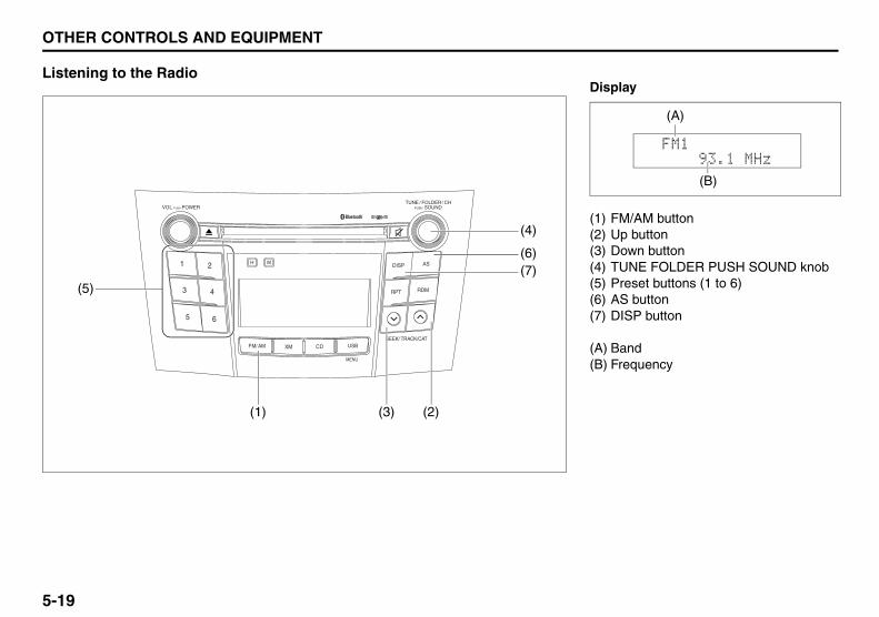
5-19
OTHER CONTROLS AND EQUIPMENT
57L20-03E
Listening to the Radio
TUNE / FOLDER / CH
DISP AS
RPT
XM USB
MENU
RDM
SEEK/ TRACK/CAT
SOUNDPUSH
1 2
3 4
5 6
VOL PUSH POWER
CDFM/ AM
H M
(5)
(4)
(1) (3) (2)
(6)(7)
Display
(1) FM/AM button(2) Up button(3) Down button(4) TUNE FOLDER PUSH SOUND knob(5) Preset buttons (1 to 6)(6) AS button(7) DISP button
(A) Band(B) Frequency
(A)
(B)

5-20
OTHER CONTROLS AND EQUIPMENT
57L20-03E
Selecting the reception bandPress the FM/AM button (1).Each time the button is pressed, thereception band is switched as follows:
Seek tuningPress the seek Up button (2) or the seekDown button (3).The unit stops searching for a station at afrequency where a broadcast station isavailable.
Manual tuningTurn the TUNE FOLDER PUSH SOUNDknob (4).The frequency being received is dis-played.
Preset memory1) Select the desired station.2) Select the Preset button (5) to which
you want to store the station and pressand hold the button for 2 seconds orlonger.
Auto storePress and hold the AS button (6) for 2 sec-onds or longer.Six stations in good reception are auto-matically stored to the Preset buttons (5)in sequential order, starting from the lowerfrequencies.
NOTE:• Auto store can be released by pressing
AS button (6) while auto store is underway.
• When the auto store is performed, thestation previously stored in the memoryat the position is overwritten.
• When there are fewer than 6 stationsthat can be stored even if 1 round ofauto store operation is performed, nostation will be stored at the remainingPreset buttons (5).
• 6 stations can be preset for FM1 andFM2 in common, and 6 stations for AMin auto store mode.
Auto store mode on/offPress the AS button (6).Each time the button is pressed, the modeis switched as follows:
Preset station callingPress the Preset button (5).The corresponding station preset can bereceived.
NOTE:If the button for a station not preset ispressed, the unit displays “- - - ”.
FM1 FM2 AM AS mode on AS mode off

5-21
OTHER CONTROLS AND EQUIPMENT
57L20-03E
Display changePress the DISP button (7).Each time it is pressed, display is changedas follows:
NOTE:• Station name display is not selectable
when no station name data is received.• “NO MESSAGE” is displayed when no
radio text data is received.• If all the text data cannot be displayed,
the “>” mark appears at the right end.Holding down the DISP button (7) for 1sec. or more calls the next page.
• The display will return to the frequencydisplay after 6 seconds.
Radio ReceptionRadio reception can be affected by envi-ronment, atmospheric conditions, or radiosignal's power and distance from the sta-tion. Nearby mountains and buildings mayinterfere or deflect radio reception, caus-ing poor reception. Poor reception or radiostatic can also be caused by electric cur-rent from overhead wires or high voltagepower lines.
Station name display/Radio text displayStation name display and radio text dis-play are not available when no data isreceived, or may not be displayed properlywhen the data is incorrectly transmitted orreceived.
Frequency display
Station name display
Radio text display

5-22
OTHER CONTROLS AND EQUIPMENT
57L20-03E
Listening to the XM Radio (if equipped)
TUNE / FOLDER / CH
DISP AS
RPT
XM USB
MENU
RDM
SEEK/ TRACK/CAT
SOUNDPUSH
1 2
3 4
5 6
VOL PUSH POWER
CDFM/ AM
H M
(1) (3) (2)
(6)(5)(5)
(4)
Display
(1) XM button(2) Up button(3) Down button(4) TUNE FOLDER PUSH SOUND knob(5) Preset buttons (1 to 6)(6) DISP button
(A) Band(B) Preset number(C) Channel number(D) Channel name
(A)
(D)
(C)(B)

5-23
OTHER CONTROLS AND EQUIPMENT
57L20-03E
Selecting the reception bandPress the XM button (1).Each time the button is pressed, thereception band is switched as follows:
Category selectionPress the Up button (2) or the Down but-ton (3).The category being received is displayed.
Channel selectionTurn the TUNE FOLDER PUSH SOUNDknob (4).The channel being received is displayed.NOTE:• “RADIO ID” is displayed with channel
000.• “Loading” is displayed during the acqui-
sition of audio data or information.
Channel selection by categoryTurn the TUNE FOLDER PUSH SOUNDknob (4) during category display. The channel being received is displayed.
Preset memory1) Select the desired channel.2) Select the Preset buttons (5) to which
you want to store the channel andpress and hold the button for 2 sec-onds or longer.
Preset channel callingPress the Preset button (5).The corresponding channel preset can bereceived.
NOTE:If the button for a channel not preset ispressed, the unit displays “- - - ”.
Display changePress the DISP button (6).Each time it is pressed, display is changedas follows:
XM ReceptionXM reception can be affected by atmo-spheric conditions. Nearby buildings orunder the overhead railway may interfereor deflect reception, causing poor recep-tion.
XM1 XM2 XM3 Channel name/Channel number display
Song (program) title display
Artist (feature) name display

5-24
OTHER CONTROLS AND EQUIPMENT
57L20-03E
Listening to a CD
TUNE / FOLDER / CH
DISP AS
RPT
XM USB
MENU
RDM
SEEK/ TRACK/CAT
SOUNDPUSH
1 2
3 4
5 6
VOL PUSH POWER
CDFM/ AM
H M
(3) (5) (4)
(8)
(6)(7)
(2) (1)
Display
(1) Insertion slot(2) Eject button(3) CD button(4) Up button(5) Down button(6) RPT button(7) RDM button(8) DISP button
(A) Track number(B) Play time
(B)
(A)

5-25
OTHER CONTROLS AND EQUIPMENT
57L20-03E
• CDs or CD-ROMs carrying no mark (A)cannot be used.
• Some discs previously recorded in CD-R\CD-RW format may not be used.
• A CD is inserted with its label facingupward.
• When there is a CD already loaded inthe unit, another CD cannot be loadedat the same time. Do not use force wheninserting the CD into the CD insertionslot.
• If a blank disc (non recorded CD-R) isloaded in the unit, the disc will beejected.
Selecting a CD modePress the CD button (3).Each time the button is pressed, thesource is switched as follows:
Loading a CDInsert a CD in the Insertion slot (1).When a CD is loaded, play starts.
Ejecting a CDPress the Eject button (2).If you left a CD ejected for a period ofabout 15 seconds, it will be automaticallydrawn inside the unit. (Auto reload func-tion, only at ACC off)
The backup eject function:This function allows you to eject a CD withthe ACC power turned off by pressing theEject button (2).
Listening to a CDWhen a CD is inserted, it is automaticallyplayed back.When a CD is already inside the unit,press the CD button (3) to play back theCD.
(A)
CAUTION
• Never insert your finger or handinto the CD insertion slot. Neverinsert foreign objects.
• Never insert a CD with glue comingout from adhesive tape or a rentalCD label or with a trace indicatingthat adhesive tape or a rental CDlabel has been removed. This maycause the CD not to eject or resultin a malfunction.
CD Bluetooth® audio
CAUTION
If you forcefully try to push an ejectedCD inside the unit before auto reload-ing, the disc surface might bescratched.Eject completely before reloading.

5-26
OTHER CONTROLS AND EQUIPMENT
57L20-03E
Selecting a track• Press the Up button (4) to listen to the
next track.• Press the Down button (5) twice to listen
to the previous track.When the Down button (5) is pressedonce, the track currently being playedwill start again at the beginning.
Fast forwarding/Rewinding a track• Hold in the Up button (4) to advance a
track rapidly.• Hold in the Down button (5) to rewind a
track.
Random playPress the RDM button (7).Each time the button is pressed, the modechanges in the following order.
NOTE:To cancel repeat play, press the RPT but-ton (6) to change the repeat play mode toOFF.
• TRACK REPEATThe repeat indicator “RPT” lights.The track being currently played isplayed repeatedly.
Repeat playPress the RPT button (6).Each time the button is pressed, repeatplay mode changes as follows:
NOTE:To cancel repeat play, press the RPT but-ton (6) to change the repeat play mode toOFF.• TRACK REPEAT
The repeat indicator “RPT” lights.The track being currently played isplayed repeatedly.
Display changePress the DISP button (8).Each time it is pressed, display is changedas follows:
NOTE:• “NO TITLE” is displayed when there is
no information on the disc.• If all the text data cannot be displayed,
the “>” mark appears at the right end.Holding down the DISP button (8) for 1sec. or more calls the next page.
OFF TRACK RANDOM
OFF TRACK REPEAT
Play time display
Disc title display
Track title display

5-27
OTHER CONTROLS AND EQUIPMENT
57L20-03E
Listening to an MP3/WMA Disc
TUNE / FOLDER / CH
DISP AS
RPT
XM USB
MENU
RDM
SEEK/ TRACK/CAT
SOUNDPUSH
1 2
3 4
5 6
VOL PUSH POWER
CDFM/ AM
H M
(3) (2)
(6)
(4)(5)
(1)
Display
(1) TUNE FOLDER PUSH SOUND knob(2) Up button(3) Down button(4) RPT button(5) RDM button(6) DISP button
(A) Folder number(B) Track number(C) Play time(D) MP3/WMA indicator
(C)
(B)(A)
(D)

5-28
OTHER CONTROLS AND EQUIPMENT
57L20-03E
Selecting a folderTurn the TUNE FOLDER PUSH SOUNDknob (1) to select a folder.
Selecting a track• Press the Up button (2) to listen to the
next track.• Press the Down button (3) twice to listen
to the previous track.When the Down button (3) is pressedonce, the track currently being playedwill start again at the beginning.
Fast forwarding/Rewinding a track• Hold in the Up button (2) to advance a
track rapidly.• Hold in the Down button (3) to rewind a
track.
Random playPress the RDM button (5).Each time the button is pressed, the modechanges in the following order.
NOTE:To cancel random play, press the RDMbutton (5) several times to change the ran-dom play mode to OFF.
• FOLDER RANDOMThe random indicator “RDM.F” lights.The tracks in the current folder areplayed at random.
• ALL RANDOMThe random indicator “RDM” lights.The tracks in the disc that is loaded areplayed at random.
Repeat playPress the RPT button (4).Each time the button is pressed, repeatplay mode changes as follows:
NOTE:To cancel repeat play, press the RPT but-ton (4) several times to change the repeatplay mode to OFF.• FILE REPEAT
The repeat indicator “RPT” lights.The track currently being played isplayed repeatedly.
• FOLDER REPEATThe repeat indicator “RPT.F” lights.All the tracks in the folder currentlybeing played are played repeatedly.
OFF FOLDER RANDOM ALL RANDOM OFF FILE REPEAT FOLDER REPEAT

5-29
OTHER CONTROLS AND EQUIPMENT
57L20-03E
Display changePress the DISP button (6).Each time it is pressed, display is changedas follows:
NOTE:• “NO TITLE” is displayed when there is
no information on the disc.• If all the text data cannot be displayed,
the “>” mark appears at the right end.Holding down the DISP button (6) for 1sec. or more calls the next page.
Play time display
Folder name display
File name display
Album name display (MP3 only)
Track title display
Artist name display

5-30
OTHER CONTROLS AND EQUIPMENT
57L20-03E
Notes on MP3/WMAWhat is MP3/WMA?MP3 (MPEG1/2 Audio Layer-III) and WMA(Windows MediaTM Audio) are the com-pression formats of digital audio. Theformer is developed by MPEG (Motion Pic-ture Experts Group), and the latter isdeveloped by Microsoft Corporation.Using these compression formats, youcan record the contents of about 10 musicCDs on a single CD media (This figuresrefer to data recorded on a 650 MB CD-Ror CD-RW at a fixed bit rate of 128 kbpsand a sampling frequency of 44.1 kHz).
Points to remember when making MP3/WMA filesCommon• High bit rate and high sampling fre-
quency are recommended for high qual-ity sounds.
• Selecting VBR (Variable Bit Rate) is notrecommended because playing time isnot displayed properly and sound maybe skipped.
• The playback sound quality differsdepending on the encoding circum-stances. For details, refer to the usermanual of your own encoding softwareand writing software.
MP3• It is recommended to set the bit rate to
“128 kbps or more” and “fixed”.
WMA• It is recommended to set the bit rate to
“64 kbps or more” and “fixed”.• Do not set the copy protect attribute on
the WMA file to enable this unit to playback.
NOTE:Never assign the “.mp3”, or “.wma” filename extension to a file that is not in theMP3/WMA format. This may not only pro-duce noise from the speaker damage, butalso damage your hearing.
Recording MP3/WMA files on a CDmedia• You are recommended to minimize the
chances of making a disc that containsboth CD-DA files and MP3/WMA files.
• If CD-DA files are on the same disc asMP3 or WMA files, the songs may notplay in the intended order, or somesongs may not play at all.
• When storing MP3 data and WMA dataon the same disc, use different foldersfor each data.
• Do not record files other than MP3/WMA files and unnecessary folder on a
disc.• The name of an MP3/WMA file should
be added by rules as shown in the fol-lowing descriptions and also complywith the rules of each file system.
• The file extension “.mp3” or “.wma”should be assigned to each file depend-ing on the file format.
• You may encounter trouble in playingMP3/WMA files or displaying the infor-mation of MP3/WMA files recorded withcertain writing software or CD record-ers.
• This unit does not have a play list func-tion.
• Although Multi-session recording is sup-ported, the use of Disc-at-Once is rec-ommended.
Compression formatsMP3• Bit rate:
MPEG1 Audio Layer III : 64 k - 320 kbpsMPEG2 Audio Layer III : 64 k - 160 kbps
• Sampling frequency:MPEG1 Audio Layer III : 32 k/44.1 k/48 kHzMPEG2 Audio Layer III : 16 k/22.05 k/24 kHz
WMA (Ver.7, Ver.8)• Bit rate: CBR 48 k - 192 kbps• Sampling frequency: 32 k/44.1 k/48 kHz

5-31
OTHER CONTROLS AND EQUIPMENT
57L20-03E
WMA (Ver. 9*)• Bit rate: CBR 48 k - 320 kbps• Sampling frequency: 32 k/44.1 k/48 kHz* WMA 9 Professional/LossLess/Voice are
not supported.
Supported file systemsISO 9660 Level 1/Level 2, Joliet, Romeo
Maximum number of files/folders• Maximum number of files: 512 (files +
folders)• Maximum number of files in one folder:
512• Maximum depth of trees: 8• Maximum number of folders: 255
(Root folder is included.)

5-32
OTHER CONTROLS AND EQUIPMENT
57L20-03E
Listening to the file stored in the USB device
TUNE / FOLDER / CH
DISP AS
RPT
XM USB
MENU
RDM
SEEK/ TRACK/CAT
SOUNDPUSH
1 2
3 4
5 6
VOL PUSH POWER
CDFM/ AM
H M
(4) (3)
(7)
(5)(6)
(2)
(1)
Display
(1) USB button(2) TUNE FOLDER PUSH SOUND knob(3) Up button(4) Down button(5) RPT button(6) RDM button(7) DISP button
(A) Folder number(B) Track number(C) Play time(D) MP3/WMA indicator
(C)
(B)(A)
(D)

5-33
OTHER CONTROLS AND EQUIPMENT
57L20-03E
Selecting a USB device modePress the USB button (1).
Selecting a folderTurn the sound control knob (2) to select afolder.
Selecting a track• Press the Up button (3) to listen to the
next track.• Press the Down button (4) twice to listen
to the previous track.When the Down button (4) is pressedonce, the track currently being playedwill start again at the beginning.
Fast forwarding/Rewinding a track• Hold in the Up button (3) to advance a
track rapidly.• Hold in the Down button (4) to rewind a
track.
Random playPress the RDM button (6).Each time the button is pressed, the modechanges in the following order.
NOTE:To cancel random play, press the RDMbutton (6) several times to change the ran-dom play mode to OFF.
• FOLDER RANDOMThe random indicator “RDM.F” lights.The tracks in the current folder areplayed at random.
• ALL RANDOMThe random indicator “RDM” lights.The tracks in the USB device that isconnected are played at random.
Repeat playPress the RPT button (5).Each time the button is pressed, repeatplay mode changes as follows:
NOTE:To cancel repeat play, press the RPT but-ton (5) several times to change the repeatplay mode to OFF.• FILE REPEAT
The repeat indicator “RPT” lights.The track currently being played isplayed repeatedly.
• FOLDER REPEATThe repeat indicator “RPT.F” lights.All the tracks in the folder currentlybeing played are played repeatedly.
CAUTION
Do not connect any USB deviceother than a USB memory or aUSB audio player. Do not con-nect multiple USB devices to theUSB connector. Supplying powerto multiple USB devices from theconnector could cause overheat-ing and smoking.
OFF FOLDER RANDOM ALL RANDOM OFF FILE REPEAT FOLDER REPEAT

5-34
OTHER CONTROLS AND EQUIPMENT
57L20-03E
Display changePress the DISP button (7).Each time it is pressed, display is changedas follows:
NOTE:• “NO TITLE” is displayed when there is
no information on the disc.• If all the text data cannot be displayed,
the “>” mark appears at the right end.Holding down the DISP button (7) for1 sec. or more calls the next page.
Notes on USB deviceCompatible USB devices• USB Mass Storage Class
For details as to whether your USBmemory/USB Audio is compatible withUSB Mass Storage Class, please con-tact the USB memory/USB Audio manu-facturer.
• USB Standard Compatibility 1.1/2.0 FullSpeed
• File System FAT16/32• Maximum current less than 500 mA• Capacity less than 4 GB (1 partition)
USB device connection• When connecting a USB device, make
sure the connector is pushed all the wayinto the socket.
• Do not leave the USB device for longperiods of time in places inside the carwhere the temperature rises too high.
• Back up any important data beforehand.We cannot accept responsibility for anylost data.
• The use of USB devices that containdata files other than MP3/WMA formatis not recommended.
Recording MP3/WMA files on a USB device• Playback or display may not be possible
depending on the type of USB device orthe condition of the recording.
• Depending on the connected USBmemory, the order in which the files areplayed back may differ from the order inwhich the files were stored.
Compression formatsMP3• Bit rate:
MPEG1 Audio Layer III : 64 k - 320 kbpsMPEG2 Audio Layer III : 64 k - 160 kbps
• Sampling frequency: MPEG1 Audio Layer III : 32 k/44.1 k/48 kHzMPEG2 Audio Layer III : 16 k/22.05 k/24 kHz
WMA (Ver.7, Ver.8)• Bit rate: CBR 48 k - 192 kbps• Sampling frequency: 32 k/44.1 k/48 kHzWMA (Ver. 9*)• Bit rate: CBR 48 k - 320 kbps• Sampling frequency: 32 k/44.1 k/48 kHz* WMA 9 Professional/LossLess/Voice are
not supported.
Maximum number of files/folders• Maximum number of files: 2500 (files +
folders)• Maximum number of files in one folder: 255• Maximum depth of trees: 8• Maximum number of folders: 255
(Root folder is included.)
Play time display
Folder name display
File name display
Album name display (MP3 only)
Track title display
Artist name display

5-35
OTHER CONTROLS AND EQUIPMENT
57L20-03E
Listening to an iPod®
TUNE / FOLDER / CH
DISP AS
RPT
XM USB
MENU
RDM
SEEK/ TRACK/CAT
SOUNDPUSH
1 2
3 4
5 6
VOL PUSH POWER
CDFM/ AM
H M
(4) (3)
(7)
(5)(6)
(2)
(1)
Display
(1) USB button(2) TUNE FOLDER PUSH SOUND knob(3) Up button(4) Down button(5) RPT button(6) RDM button(7) DISP button
(A) Track title(B) Track number(C) Play time
(C)
(A)
(B)

5-36
OTHER CONTROLS AND EQUIPMENT
57L20-03E
Selecting an iPod® modePress the USB button (1).
Selecting a track• Press the Up button (3) to listen to the
next track.• Press the Down button (4) twice to listen
to the previous track.When the Down button (4) is pressedonce, the track currently being playedwill start again at the beginning.
Fast forwarding/Rewinding a track• Hold in the Up button (3) to advance a
track rapidly.• Hold in the Down button (4) to rewind a
track.
Random playPress the RDM button (6).Each time the button is pressed, the modechanges in the following order.
NOTE:To cancel random play, press the RDMbutton (6) several times to change the ran-dom play mode to OFF.
• SONG RANDOMThe random indicator “RDM” lights.The tracks in the iPod® are played atrandom.
• ALBUM RANDOMThe random indicator “D.RDM” lights.The albums in the iPod® that are playedat random.
Repeat playPress the RPT button (5).Each time the button is pressed, repeatplay mode changes as follows:
NOTE:To cancel repeat play, press the RPT but-ton (5) again.• SONG REPEAT
The repeat indicator “RPT” lights.The track currently being played isplayed repeatedly.
OFF SONG RANDOM ALBUM RANDOM OFF SONG REPEAT

5-37
OTHER CONTROLS AND EQUIPMENT
57L20-03E
Display changePress the DISP button (7).Each time it is pressed, display is changedas follows:
NOTE:If all the text data cannot be displayed, the“>” mark appears at the right end. Holdingdown the DISP button (7) for 1 sec. ormore calls the next page.
Playing Mode selection1) Press and hold the USB button (1) for
1 second or longer.2) Turn the TUNE FOLDER PUSH
SOUND knob (2).Each time it is turned, mode ischanged as follows:
3) Press the TUNE FOLDER PUSHSOUND knob (2) to select an item.
NOTE:• When the USB button (1) is pressed, the
previous screen appears.• When the DISP button (7) is pressed,
the regular screen appears.• “NO SONGS” will appear if no song
exists.
Notes on iPod®
Controllable iPod®/software version• iPod® touch• iPod® classic• iPod® nano (4th generation)• iPod® nano (3rd generation)• iPod® nano (2nd generation)• iPod® nano (1st generation)• iPod® (5th generation)* Please update the firmware of your
iPod® before using it.Some functions may not be availabledepending on the model of iPod® or itsfirmware version.
• iPod® is a trademark of Apple Inc., reg-istered in the U.S. and other countries.
• Apple is not responsible for the opera-tion of this device or its compliance withsafety and regulatory standards.
iPod® connection• Please make sure to detach the iPod®
after turning off the car engine (turningthe ACC to OFF). The iPod® may notshut down while still connected, whichmay result in battery depletion.
• Please do not connect iPod® accesso-ries such as an iPod® remote control orheadphones while connecting iPod®
with the unit. The unit may not operatecorrectly.
Playlist name & Track title display(Playlist mode only)
Artist name & Track title display
Album name & Track title display
Track title & Play time display
PLAYLIST
ARTIST
ALBUM
SONGS
GENRE

5-38
OTHER CONTROLS AND EQUIPMENT
57L20-03E
Bluetooth® Hands-Free (if equipped)
(1) TUNE FOLDER PUSH SOUND knob(2) VOL PUSH POWER knob(3) Preset buttons(4) DISP button(5) RDM button
TUNE / FOLDER / CH
DISP AS
RPT
XM USB
MENU
RDM
SEEK/ TRACK/CAT
SOUNDPUSH
1 2
3 4
5 6
VOL PUSH POWER
CDFM/ AM
H M (4)
(1)
(3)
(2)
(5)
Hands-free switches
(6) Talk button(7) Off Hook button(8) On Hook button(9) VOL switch
(6)
(7)
(8)
(9)

5-39
OTHER CONTROLS AND EQUIPMENT
57L20-03E
Bluetooth® language selectionThe language used for the voice guidance,menu, and voice recognition can beselected. (Default: English)1) Press the Off Hook button (7).
The hands-free mode is activated.2) Hold down RDM button (5) for 2 sec. or
more. 3) Turn the TUNE FOLDER PUSH
SOUND knob (1) to select a language,and press the TUNE FOLDER PUSHSOUND knob (1) to determine theselection.
NOTE:The regular screen resumes if no opera-tion is performed for 5 sec. or more.
Telephone registration
NOTE:• Up to 6 telephones can be registered. • To set up a new phone, disconnect the
system from the audio player. The audioplayer shall be reconnected after phonesetup is completed.
• If connection cannot be confirmed within120 seconds, the connecting operationis canceled. Please try again or refer tothe Phone's manual for assistance withthe pairing process.
1) Press the Off Hook button (7). The Bluetooth® main menu appears.
2) Turn the TUNE FOLDER PUSHSOUND knob (1) to select “PairPhone”, and press the TUNE FOLDERPUSH SOUND knob (1) to determinethe selection.
3) Turn the TUNE FOLDER PUSHSOUND knob (1) to select “RecordName”, and press the TUNE FOLDERPUSH SOUND knob (1) to determinethe selection.
4) Pronounce the name to be used atvoice recognition.
5) Turn the TUNE FOLDER PUSHSOUND knob (1) to select “Confirm”,and press the TUNE FOLDER PUSHSOUND knob (1) to determine theselection.
6) Turn the TUNE FOLDER PUSHSOUND knob (1) to select “PhoneOnly” or “Int. Audio”, and press theTUNE FOLDER PUSH SOUND knob(1) to determine the selection. “Phone Only” shall be selected forusing only as the telephone, and“Int.Audio” shall be selected for usingas the built-in audio equipment as wellas the telephone.
7) Select “CAR_M.MEDIA” from theBluetooth® menu of the cell phone andmake a connection. Refer to the manual of your cell phonefor further information.
8) Enter the Passkey displayed on thesystem into the cell phone.
9) Press the On Hook button (8).NOTE:• Selection of “Go Back” displays the pre-
vious menu.• If you select “Pair Phone” at step 8, you
can register the other phones continu-ously.
To activate the hands-free function withthis unit, your cell phone needs to beregistered.

5-40
OTHER CONTROLS AND EQUIPMENT
57L20-03E
Receiving a callPress the Off Hook button (7) to receive acall.
Ending a callPress the On Hook button (8) to end a call.
Rejecting a call (only for supported-models)Press the On Hook button (8) to reject aincoming call.
Adjusting the listening volume• Turn the VOL PUSH POWER knob (2)
during a call.Turning it clockwise increases the vol-ume; turning it counterclockwisedecreases the volume.
• Lean the VOL switch (9) during a call.Leaning to the upper side increases thevolume; leaning the lower sidedecreases the volume.
Adjusting the ring volume• Turn the VOL PUSH POWER knob (2)
while a call coming in.Turning it clockwise increases the vol-ume; turning it counterclockwisedecreases the volume.
• Lean the VOL switch (9) while a callcoming in.Leaning to the upper side increases thevolume; leaning the lower sidedecreases the volume.
Dialing by using Redial/CallbackThe last dialed number is dialed. NOTE:Up to latest 5 calls can be stored for each.1) Press the Off Hook button (7).
The Bluetooth® main menu appears. 2) Turn the TUNE FOLDER PUSH
SOUND knob (1) to select “Redial” or“Callback”, and press the TUNEFOLDER PUSH SOUND knob (1) todetermine the selection. For calling from the outgoing callrecord or incoming call record, “Redial”or “Callback” shall be selected, respec-tively.
3) Turn the TUNE FOLDER PUSHSOUND knob (1) to select a number,and press the TUNE FOLDER PUSHSOUND knob (1) to determine theselection.
4) Turn the TUNE FOLDER PUSHSOUND knob (1) to select “Dial”, andpress the TUNE FOLDER PUSHSOUND knob (1) to determine theselection. The selected number is dialed.
NOTE:• Selection of “Go Back” displays the pre-
vious menu.• Pressing the Off Hook button (7) in the
2nd step allows users to forward to the3rd step with a single motion.

5-41
OTHER CONTROLS AND EQUIPMENT
57L20-03E
• Pressing “Confirm” after selecting“Store” allows the selected number to beregistered to the Phonebook.
• Pressing “Confirm” after selecting“Delete” allows the selected number tobe deleted from the list.
Registration in PhonebookA telephone number is registered to thePhonebook.1) Press the Off Hook button (7).
The Bluetooth® main menu appears.2) Turn the TUNE FOLDER PUSH
SOUND knob (1) to select “Phone-book”, and press the TUNE FOLDERPUSH SOUND knob (1) to determinethe selection.
3) Turn the TUNE FOLDER PUSHSOUND knob (1) to select “Add Entry”,and press the TUNE FOLDER PUSHSOUND knob (1) to determine theselection.
4) Turn the TUNE FOLDER PUSHSOUND knob (1) to select “By Voice”,“By Phone”, “Manual Input” or “CallHistory”, and press the TUNEFOLDER PUSH SOUND knob (1) todetermine the selection."By Voice": Registers through thevoice command."By Phone": Registers through thetelephone. "Manual Input": Registers with use ofthe TUNE FOLDER PUSH SOUNDknob (1)."Call History": Registers through theincoming/outgoing call records.
5) Press the Talk button (6) and pro-nounce a registered name.
6) Turn the TUNE FOLDER PUSHSOUND knob (1) to select “Confirm”,and press the TUNE FOLDER PUSHSOUND knob (1) to determine theselection.
NOTE:• Selection of “Go Back” displays the pre-
vious menu.• Up to 20 numbers can be registered in
Phonebook.

5-42
OTHER CONTROLS AND EQUIPMENT
57L20-03E
Name change (Change Name)The name of number registered in phonebookis changed.1) Press the Off Hook button (7).
The Bluetooth® main menu appears.2) Turn the TUNE FOLDER PUSH SOUND
knob (1) to select “Phonebook”, andpress the TUNE FOLDER PUSH SOUNDknob (1) to determine the selection.
3) Turn the TUNE FOLDER PUSH SOUNDknob (1) to select “Change Name”, andpress the TUNE FOLDER PUSH SOUNDknob (1) to determine the selection.
4) Turn the TUNE FOLDER PUSH SOUNDknob (1) to select a number to bechanged, and press the TUNE FOLDERPUSH SOUND knob (1) to determine theselection.
5) Turn the TUNE FOLDER PUSH SOUNDknob (1) to select “Record Name”, andpress the TUNE FOLDER PUSH SOUNDknob (1) to determine the selection.
6) Pronounce the name to be used at voicerecognition.
7) Turn the TUNE FOLDER PUSH SOUNDknob (1) to select “Confirm”, and pressthe TUNE FOLDER PUSH SOUND knob(1) to determine the selection.
NOTE: Selection of “Go Back” displays the previousmenu.
Making a call by PhonebookThe number registered in Phonebook isdialed.1) Press the Off Hook button (7).
The Bluetooth® main menu appears. 2) Turn the TUNE FOLDER PUSH
SOUND knob (1) to select “Phone-book”, and press the TUNE FOLDERPUSH SOUND knob (1) to determinethe selection.
3) Turn the TUNE FOLDER PUSHSOUND knob (1) to select “ListNames”, and press the TUNEFOLDER PUSH SOUND knob (1) todetermine the selection.The registered numbers are displayedin sequence.
4) Press the Off Hook button (7).The displayed number is dialed.
Deletion of registered data (DeleteEntry)The number registered in Phonebook isdeleted.1) Press the Off Hook button (7).
The Bluetooth® main menu appears.2) Turn the TUNE FOLDER PUSH
SOUND knob (1) to select “Phone-book”, and press the TUNE FOLDERPUSH SOUND knob (1) to determinethe selection.
3) Turn the TUNE FOLDER PUSHSOUND knob (1) to select “DeleteEntry”, and press the TUNE FOLDERPUSH SOUND knob (1) to determinethe selection.
4) Turn the TUNE FOLDER PUSHSOUND knob (1) to select a number tobe deleted, and press the TUNEFOLDER PUSH SOUND knob (1) todetermine the selection.
5) Turn the TUNE FOLDER PUSHSOUND knob (1) to select “Confirm”,and press the TUNE FOLDER PUSHSOUND knob (1) to determine theselection.
NOTE:Selection of “Go Back” displays the previ-ous menu.

5-43
OTHER CONTROLS AND EQUIPMENT
57L20-03E
One-touch call (Speed dial)One of the numbers registered to the Pre-set buttons (3) is dialed.1) Press the Off Hook button (7).
The hands-free mode is activated. 2) Press one of the Preset buttons (3).
The registered name is pronounced. When no registered name is found,“Empty” is pronounced.
3) Press the Off Hook button (7). The selected number is dialed.
Registration in speed dialA telephone number is registered to thespeed dial.1) Press the Off Hook button (7).
The Bluetooth® main menu appears. 2) Turn the TUNE FOLDER PUSH
SOUND knob (1) to select “Phone-book”, and press the TUNE FOLDERPUSH SOUND knob (1) to determinethe selection.
3) Turn the TUNE FOLDER PUSHSOUND knob (1) to select “SpeedDial”, and press the TUNE FOLDERPUSH SOUND knob (1) to determinethe selection.
4) Turn the TUNE FOLDER PUSHSOUND knob (1) to select a number tobe registered, and press the TUNEFOLDER PUSH SOUND knob (1) todetermine the selection.
5) Press one of the Preset buttons (3), towhich the selected number is regis-tered. If a number is already registered to theselected button, a confirmation mes-sage is displayed. Turn the TUNEFOLDER PUSH SOUND knob (1) toselect “Confirm”, and press the TUNEFOLDER PUSH SOUND knob (1) todetermine the selection.
NOTE:Selection of “Go Back” displays the previ-ous menu.
Deletion of speed dial (Del Spd Dial)The numbers registered to the speed dialis deleted.1) Press the Off Hook button (7).
The Bluetooth® main menu appears. 2) Turn the TUNE FOLDER PUSH
SOUND knob (1) to select “Phone-book”, and press the TUNE FOLDERPUSH SOUND knob (1) to determinethe selection.
3) Turn the TUNE FOLDER PUSHSOUND knob (1) to select “Del SpdDial”, and press the TUNE FOLDERPUSH SOUND knob (1) to determinethe selection.
4) Press one of the Preset buttons (3), towhich the selected number is regis-tered.
5) Turn the TUNE FOLDER PUSHSOUND knob (1) to select “Confirm”,and press the TUNE FOLDER PUSHSOUND knob (1) to determine theselection.
NOTE:Selection of “Go Back” displays the previ-ous menu.

5-44
OTHER CONTROLS AND EQUIPMENT
57L20-03E
Security number (PIN)The security number (PIN) is specified. Once PIN is specified, PIN entry isrequired when toggling Phonebookbetween locking and unlocking.1) Press the Off Hook button (7).
The Bluetooth® main menu appears. 2) Turn the TUNE FOLDER PUSH
SOUND knob (1) to select “Setup”,and press the TUNE FOLDER PUSHSOUND knob (1) to determine theselection.
3) Turn the TUNE FOLDER PUSHSOUND knob (1) to select “Security”,and press the TUNE FOLDER PUSHSOUND knob (1) to determine theselection.
4) Turn the TUNE FOLDER PUSHSOUND knob (1) to select “Set PIN”,and press the TUNE FOLDER PUSHSOUND knob (1) to determine theselection.If the PIN is already specified, PINentry is required. If the PIN needs tobe changed, enter the current PIN.
5) Turn the TUNE FOLDER PUSHSOUND knob (1) to select a numberfor ones digit, and press the TUNEFOLDER PUSH SOUND knob (1) todetermine the selection. Determine thetens, hundreds, and thousands digitsin the same manner.
6) Turn the TUNE FOLDER PUSHSOUND knob (1) to select “Confirm”,and press the TUNE FOLDER PUSHSOUND knob (1) to determine theselection.
NOTE:Selection of “Go Back” displays the previ-ous menu.
Phonebook lockLocking Phonebook disables users fromreferring to, using, editing, and deletingPhonebook, outgoing call record, andincoming call record. 1) Press the Off Hook button (7).
The Bluetooth® main menu appears. 2) Turn the TUNE FOLDER PUSH
SOUND knob (1) to select “Setup”,and press the TUNE FOLDER PUSHSOUND knob (1) to determine theselection.
3) Turn the TUNE FOLDER PUSHSOUND knob (1) to select “Security”,and press the TUNE FOLDER PUSHSOUND knob (1) to determine theselection.
4) Turn the TUNE FOLDER PUSHSOUND knob (1) to select “PhbkLock”, and press the TUNE FOLDERPUSH SOUND knob (1) to determinethe selection.If Phonebook is already set to Lock,“Phbk Lock.” is displayed.
5) Enter a PIN number. NOTE:Selection of “Go Back” displays the previ-ous menu.

5-45
OTHER CONTROLS AND EQUIPMENT
57L20-03E
Phonebook unlock1) Press the Off Hook button (7).
The Bluetooth® main menu appears. 2) Turn the TUNE FOLDER PUSH
SOUND knob (1) to select “Setup”,and press the TUNE FOLDER PUSHSOUND knob (1) to determine theselection.
3) Turn the TUNE FOLDER PUSHSOUND knob (1) to select “Security”,and press the TUNE FOLDER PUSHSOUND knob (1) to determine theselection.
4) Turn the TUNE FOLDER PUSHSOUND knob (1) to select “PhbkUnlock”, and press the TUNEFOLDER PUSH SOUND knob (1) todetermine the selection.If Phonebook is already set to Unlock,“Phbk Unlock.” is displayed.
5) Enter a PIN number. NOTE:Selection of “Go Back” displays the previ-ous menu.
Adjusting the guidance volumeYou can adjust the guidance volume.1) Press the Off Hook button (7).
The Bluetooth® main menu appears. 2) Turn the TUNE FOLDER PUSH
SOUND knob (1) to select “Setup”,and press the TUNE FOLDER PUSHSOUND knob (1) to determine theselection.
3) Turn the TUNE FOLDER PUSHSOUND knob (1) to select “SystemSetup”, and press the TUNE FOLDERPUSH SOUND knob (1) to determinethe selection.
4) Turn the TUNE FOLDER PUSHSOUND knob (1) to select “GuidanceVol”, and press the TUNE FOLDERPUSH SOUND knob (1) to determinethe selection.The current guidance volume is dis-played.
5) Turn the TUNE FOLDER PUSHSOUND knob (1) to select guidancevolume, and press the TUNE FOLDERPUSH SOUND knob (1) to determinethe selection.
NOTE:Selection of “Go Back” displays the previ-ous menu.
Display of device data (Device Name)BD address and device name is displayed.1) Press the Off Hook button (7).
The Bluetooth® main menu appears. 2) Turn the TUNE FOLDER PUSH
SOUND knob (1) to select “Setup”,and press the TUNE FOLDER PUSHSOUND knob (1) to determine theselection.
3) Turn the TUNE FOLDER PUSHSOUND knob (1) to select “SystemSetup”, and press the TUNE FOLDERPUSH SOUND knob (1) to determinethe selection.
4) Turn the TUNE FOLDER PUSHSOUND knob (1) to select “DeviceName”, and press the TUNE FOLDERPUSH SOUND knob (1) to determinethe selection.
5) Turn the TUNE FOLDER PUSHSOUND knob (1) to display the BDaddress and the device name.
NOTE:Selection of “Go Back” displays the previ-ous menu.

5-46
OTHER CONTROLS AND EQUIPMENT
57L20-03E
Reset to factory defaultsYou can delete all registered data andreset the all changement to the factorydefault.1) Press the Off Hook button (7).
The Bluetooth® main menu appears. 2) Turn the TUNE FOLDER PUSH
SOUND knob (1) to select “Setup”,and press the TUNE FOLDER PUSHSOUND knob (1) to determine theselection.
3) Turn the TUNE FOLDER PUSHSOUND knob (1) to select “SystemSetup”, and press the TUNE FOLDERPUSH SOUND knob (1) to determinethe selection.
4) Turn the TUNE FOLDER PUSHSOUND knob (1) to select “Initialize”,and press the TUNE FOLDER PUSHSOUND knob (1) to determine theselection.
5) Turn the TUNE FOLDER PUSHSOUND knob (1) to select “Confirm”,and press the TUNE FOLDER PUSHSOUND knob (1) to determine theselection.
6) Turn the TUNE FOLDER PUSHSOUND knob (1) to select “Confirm”,and press the TUNE FOLDER PUSHSOUND knob (1) to determine theselection.
NOTE:Selection of “Go Back” displays the previ-ous menu.
Selection of telephone (Select Phone)The phone to be used can be selected.1) Press the Off Hook button (7).
The Bluetooth® main menu appears. 2) Turn the TUNE FOLDER PUSH SOUND
knob (1) to select “Setup”, and press theTUNE FOLDER PUSH SOUND knob (1)to determine the selection.
3) Turn the TUNE FOLDER PUSH SOUNDknob (1) to select “Phone Setup”, andpress the TUNE FOLDER PUSHSOUND knob (1) to determine the selec-tion.
4) Turn the TUNE FOLDER PUSH SOUNDknob (1) to select “Select Phone”, andpress the TUNE FOLDER PUSHSOUND knob (1) to determine the selec-tion.
5) Turn the TUNE FOLDER PUSH SOUNDknob (1) to select a phone to be paired,and press the TUNE FOLDER PUSHSOUND knob (1) to determine the selec-tion.
6) Turn the TUNE FOLDER PUSH SOUNDknob (1) to select “Confirm”, and pressthe TUNE FOLDER PUSH SOUND knob(1) to determine the selection.
NOTE:• Selection of “Go Back” displays the previ-
ous menu.• The Bluetooth®-ready audio device will be
disconnected when the phone is selected.
Name change (Change Name)The registered name of phones arechanged.1) Press the Off Hook button (7).
The Bluetooth® main menu appears. 2) Turn the TUNE FOLDER PUSH
SOUND knob (1) to select “Setup”,and press the TUNE FOLDER PUSHSOUND knob (1) to determine theselection.
3) Turn the TUNE FOLDER PUSHSOUND knob (1) to select “PhoneSetup”, and press the TUNE FOLDERPUSH SOUND knob (1) to determinethe selection.
4) Turn the TUNE FOLDER PUSHSOUND knob (1) to select “ChangeName”, and press the TUNE FOLDERPUSH SOUND knob (1) to determinethe selection.
5) Turn the TUNE FOLDER PUSHSOUND knob (1) to select a phone tobe changed, and press the TUNEFOLDER PUSH SOUND knob (1) todetermine the selection.
6) Turn the TUNE FOLDER PUSHSOUND knob (1) to select “RecordName”, and press the TUNE FOLDERPUSH SOUND knob (1) to determinethe selection.

5-47
OTHER CONTROLS AND EQUIPMENT
57L20-03E
7) Pronounce the name to be used atvoice recognition.
8) Turn the TUNE FOLDER PUSHSOUND knob (1) to select “Confirm”,and press the TUNE FOLDER PUSHSOUND knob (1) to determine theselection.
NOTE:Selection of “Go Back” displays the previ-ous menu.
List of telephones (List Phones)The registered name of phones are dis-played in sequence.1) Press the Off Hook button (7).
The Bluetooth® main menu appears. 2) Turn the TUNE FOLDER PUSH
SOUND knob (1) to select “Setup”,and press the TUNE FOLDER PUSHSOUND knob (1) to determine theselection.
3) Turn the TUNE FOLDER PUSHSOUND knob (1) to select “PhoneSetup”, and press the TUNE FOLDERPUSH SOUND knob (1) to determinethe selection.
4) Turn the TUNE FOLDER PUSHSOUND knob (1) to select “ListPhones”, and press the TUNEFOLDER PUSH SOUND knob (1) todetermine the selection.The names of registered phones aredisplayed in sequence.
NOTE:Selection of “Go Back” displays the previ-ous menu.
Passkey setting (Set Passkey)The security number (Passkey) is speci-fied. 1) Press the Off Hook button (7).
The Bluetooth® main menu appears. 2) Turn the TUNE FOLDER PUSH
SOUND knob (1) to select “Setup”,and press the TUNE FOLDER PUSHSOUND knob (1) to determine theselection.
3) Turn the TUNE FOLDER PUSHSOUND knob (1) to select “PhoneSetup”, and press the TUNE FOLDERPUSH SOUND knob (1) to determinethe selection.
4) Turn the TUNE FOLDER PUSHSOUND knob (1) to select “Set Pass-key”, and press the TUNE FOLDERPUSH SOUND knob (1) to determinethe selection.
5) Turn the TUNE FOLDER PUSHSOUND knob (1) to select a numberfor ones digit, and press the TUNEFOLDER PUSH SOUND knob (1) todetermine the selection. Determine thetens, hundreds, and thousands digitsin the same manner.
NOTE:Selection of “Go Back” displays the previ-ous menu.

5-48
OTHER CONTROLS AND EQUIPMENT
57L20-03E
Deletion of telephone data (Delete Phone)The registered information of phone isdeleted.1) Press the Off Hook button (7).
The Bluetooth® main menu appears. 2) Turn the TUNE FOLDER PUSH SOUND
knob (1) to select “Setup”, and press theTUNE FOLDER PUSH SOUND knob (1)to determine the selection.
3) Turn the TUNE FOLDER PUSH SOUNDknob (1) to select “Phone Setup”, andpress the TUNE FOLDER PUSH SOUNDknob (1) to determine the selection.
4) Turn the TUNE FOLDER PUSH SOUNDknob (1) to select “Delete Phone”, andpress the TUNE FOLDER PUSH SOUNDknob (1) to determine the selection.
5) Turn the TUNE FOLDER PUSH SOUNDknob (1) to select a phone to be deleted,and press the TUNE FOLDER PUSHSOUND knob (1) to determine the selec-tion.
6) Turn the TUNE FOLDER PUSH SOUNDknob (1) to select “Confirm”, and pressthe TUNE FOLDER PUSH SOUND knob(1) to determine the selection.
NOTE:Selection of “Go Back” displays the previousmenu.
HF function on/off (HF Power)Toggles the Bluetooth® function on andoff. 1) Press the Off Hook button (7).
The Bluetooth® main menu appears. 2) Turn the TUNE FOLDER PUSH
SOUND knob (1) to select “Setup”,and press the TUNE FOLDER PUSHSOUND knob (1) to determine theselection.
3) Turn the TUNE FOLDER PUSHSOUND knob (1) to select “PhoneSetup”, and press the TUNE FOLDERPUSH SOUND knob (1) to determinethe selection.
4) Turn the TUNE FOLDER PUSHSOUND knob (1) to select “HF Power”,and press the TUNE FOLDER PUSHSOUND knob (1) to determine theselection.
5) Turn the TUNE FOLDER PUSHSOUND knob (1) to select “Turn on” or“Turn off” and press the TUNEFOLDER PUSH SOUND knob (1) todetermine the selection.
NOTE:Selection of “Go Back” displays the previ-ous menu.

5-49
OTHER CONTROLS AND EQUIPMENT
57L20-03E
Bluetooth® audio (if equipped)
TUNE / FOLDER / CH
DISP AS
RPT
XM USB
MENU
RDM
SEEK/ TRACK/CAT
SOUNDPUSH
1 2
3 4
5 6
VOL PUSH POWER
CDFM/ AM
H M
(4) (3)
(5)
(2)
(1)
Hands-free switches
Display
(1) CD button(2) TUNE FOLDER PUSH SOUND knob(3) Up button(4) Down button(5) DISP button(6) Off Hook button(7) Talk button
(A) Track number(B) Play time
(7)
(6)
(B)
(A)

5-50
OTHER CONTROLS AND EQUIPMENT
57L20-03E
Registration of audio devices (PairAudio, when no cell phone is regis-tered)
NOTE:• To set up a new audio player, disconnect
the system from the phone. The phoneshall be reconnected after audio playersetup is completed.
• If connection cannot be confirmed within120 seconds, the connecting operationis canceled. Please try again or refer tothe audio player manual for assistancewith the pairing process.
1) Press the CD button (1) to selectBluetooth® audio mode.“BT-A” is displayed.
2) Press the Talk button (7).The Bluetooth® main menu appears.
3) Turn the TUNE FOLDER PUSHSOUND knob (2) to select “PairAudio”, and press the TUNE FOLDERPUSH SOUND knob (2) to determinethe selection.
4) Turn the TUNE FOLDER PUSHSOUND knob (2) to select “RecordName”, and press the TUNE FOLDERPUSH SOUND knob (2) to determine
the selection.5) Pronounce the name to be used at
voice recognition. 6) Turn the TUNE FOLDER PUSH
SOUND knob (2) to select “Confirm”,and press the TUNE FOLDER PUSHSOUND knob (2) to determine theselection.
7) Select “CAR_M.MEDIA” from theBluetooth® menu of the audio playerand make a connection.Refer to the manual of your audioplayer for further information.
8) Enter the Passkey displayed on thesystem into the audio player.
NOTE:Selection of “Go Back” displays the previ-ous menu.
Registration of audio devices (PairAudio, when your cell phone is regis-tered)
NOTE:• To set up a new audio player, disconnect
the system from the phone. The phoneshall be reconnected after audio playersetup is completed.
• If connection cannot be confirmed within120 seconds, the connecting operationis canceled. Please try again or refer tothe audio player manual for assistancewith the pairing process.
1) Press the Off Hook button (6). The Bluetooth® main menu appears.
2) Turn the TUNE FOLDER PUSHSOUND knob (2) to select “Setup”,and press the TUNE FOLDER PUSHSOUND knob (2) to determine theselection.
3) Turn the TUNE FOLDER PUSHSOUND knob (2) to select “BT.ASetup”, and press the TUNE FOLDERPUSH SOUND knob (2) to determinethe selection.
To use Bluetooth®-ready audio deviceswith this unit, the devices need to beregistered.
To use Bluetooth®-ready audio deviceswith this unit, the devices need to beregistered.

5-51
OTHER CONTROLS AND EQUIPMENT
57L20-03E
4) Turn the TUNE FOLDER PUSHSOUND knob (2) to select “RecordName”, and press the TUNE FOLDERPUSH SOUND knob (2) to determinethe selection.
5) Pronounce the name to be used atvoice recognition.
6) Turn the TUNE FOLDER PUSHSOUND knob (2) to select “Confirm”,and press the TUNE FOLDER PUSHSOUND knob (2) to determine theselection.
7) Select “CAR_M.MEDIA” from theBluetooth® menu of the audio playerand make a connection.Refer to the manual of your audioplayer for further information.
8) Enter the Passkey displayed on thesystem into the audio player.
NOTE:Selection of “Go Back” displays the previ-ous menu.
Selecting the bluetooth audio modePress the CD button (1).Each time the button is pressed, thesource is switched as follows:
Selecting a group (only for supported-models)Turn the TUNE FOLDER PUSH SOUNDknob (2) to select a group.
Selecting a track• Press the Up button (3) to listen to the
next track.• Press the Down button (4) twice to listen
to the previous track.When the Down button (4) is pressedonce, the track currently being playedwill start again at the beginning.
Fast forwarding/Rewinding a track• Hold in the Up button (3) to advance a
track rapidly.• Hold in the Down button (4) to rewind a
track.
Display changePress the DISP button (5).Each time it is pressed, display is changedas follows:
NOTE:If all the text data cannot be displayed, the“>” mark appears at the right end. Holdingdown the DISP button (5) for 1 sec. ormore calls the next page.
CD Bluetooth® audio Play time display
Track name display
Artist name display
Album name display

5-52
OTHER CONTROLS AND EQUIPMENT
57L20-03E
Selection of audio device (SelectAudio)The audio device to be used can beselected.1) Press the Off Hook button (6).
The Bluetooth® main menu appears.2) Turn the TUNE FOLDER PUSH
SOUND knob (2) to select “Setup”,and press the TUNE FOLDER PUSHSOUND knob (2) to determine theselection.
3) Turn the TUNE FOLDER PUSHSOUND knob (2) to select “BT.ASetup”, and press the TUNE FOLDERPUSH SOUND knob (2) to determinethe selection.
4) Turn the TUNE FOLDER PUSHSOUND knob (2) to select “SelectAudio”, and press the TUNE FOLDERPUSH SOUND knob (2) to determinethe selection.
5) Turn the TUNE FOLDER PUSHSOUND knob (2) to select an audiodevice to be paired, and press theTUNE FOLDER PUSH SOUND knob(2) to determine the selection.
6) Turn the TUNE FOLDER PUSHSOUND knob (2) to select “Confirm”,and press the TUNE FOLDER PUSHSOUND knob (2) to determine theselection.
7) Turn the TUNE FOLDER PUSHSOUND knob (2) to select “From Car”or “From Audio”, and press the TUNEFOLDER PUSH SOUND knob (2) todetermine the selection."From Car": Makes a pairing from theunit."From Audio": Makes a pairing fromthe audio device.
8) Turn the TUNE FOLDER PUSHSOUND knob (2) to select “Confirm”,and press the TUNE FOLDER PUSHSOUND knob (2) to determine theselection.
NOTE:• Selection of “Go Back” displays the pre-
vious menu.• The phone will be disconnected when
the Bluetooth®-ready audio device isselected.
Change of audio device name (ChangeName)The registered name of audio devices arechanged.1) Press the Off Hook button (6).
The Bluetooth® main menu appears.2) Turn the TUNE FOLDER PUSH
SOUND knob (2) to select “Setup”,and press the TUNE FOLDER PUSHSOUND knob (2) to determine theselection.
3) Turn the TUNE FOLDER PUSHSOUND knob (2) to select “BT.ASetup”, and press the TUNE FOLDERPUSH SOUND knob (2) to determinethe selection.
4) Turn the TUNE FOLDER PUSHSOUND knob (2) to select “ChangeName”, and press the TUNE FOLDERPUSH SOUND knob (2) to determinethe selection.
5) Turn the TUNE FOLDER PUSHSOUND knob (2) to select an audiodevice to be changed, and press theTUNE FOLDER PUSH SOUND knob(2) to determine the selection.
6) Turn the TUNE FOLDER PUSHSOUND knob (2) to select “RecordName”, and press the TUNE FOLDERPUSH SOUND knob (2) to determinethe selection.

5-53
OTHER CONTROLS AND EQUIPMENT
57L20-03E
7) Pronounce the name to be used atvoice recognition.
8) Turn the TUNE FOLDER PUSHSOUND knob (2) to select “Confirm”,and press the TUNE FOLDER PUSHSOUND knob (2) to determine theselection.
NOTE:Selection of “Go Back” displays the previ-ous menu.
List of audio devices (List Audio)The registered name of audio devices aredisplayed in sequence.1) Press the Off Hook button (6).
The Bluetooth® main menu appears.2) Turn the TUNE FOLDER PUSH
SOUND knob (2) to select “Setup”,and press the TUNE FOLDER PUSHSOUND knob (2) to determine theselection.
3) Turn the TUNE FOLDER PUSHSOUND knob (2) to select “BT.ASetup”, and press the TUNE FOLDERPUSH SOUND knob (2) to determinethe selection.
4) Turn the TUNE FOLDER PUSHSOUND knob (2) to select “ListAudios”, and press the TUNEFOLDER PUSH SOUND knob (2) todetermine the selection.The names of registered phones aredisplayed in sequence.
NOTE:Selection of “Go Back” displays the previ-ous menu.
Passkey setting (Set Passkey)The security number (Passkey) is speci-fied.1) Press the Off Hook button (6).
The Bluetooth® main menu appears.2) Turn the TUNE FOLDER PUSH
SOUND knob (2) to select “Setup”,and press the TUNE FOLDER PUSHSOUND knob (2) to determine theselection.
3) Turn the TUNE FOLDER PUSHSOUND knob (2) to select “BT.ASetup”, and press the TUNE FOLDERPUSH SOUND knob (2) to determinethe selection.
4) Turn the TUNE FOLDER PUSHSOUND knob (2) to select “Set Pass-key”, and press the TUNE FOLDERPUSH SOUND knob (2) to determinethe selection.
5) Turn the TUNE FOLDER PUSHSOUND knob (2) to select a numberfor ones digit, and press the TUNEFOLDER PUSH SOUND knob (2) todetermine the selection. Determine thetens, hundreds, and thousands digitsin the same manner.
NOTE:Selection of “Go Back” displays the previ-ous menu.

5-54
OTHER CONTROLS AND EQUIPMENT
57L20-03E
Deletion of connection data (DeleteAudio)The registered information of audio deviceis deleted.1) Press the Off Hook button (6).
The Bluetooth® main menu appears.2) Turn the TUNE FOLDER PUSH
SOUND knob (2) to select “Setup”,and press the TUNE FOLDER PUSHSOUND knob (2) to determine theselection.
3) Turn the TUNE FOLDER PUSHSOUND knob (2) to select “BT.ASetup”, and press the TUNE FOLDERPUSH SOUND knob (2) to determinethe selection.
4) Turn the TUNE FOLDER PUSHSOUND knob (2) to select “DeleteAudio”, and press the TUNE FOLDERPUSH SOUND knob (2) to determinethe selection.
5) Turn the TUNE FOLDER PUSHSOUND knob (2) to select an audiodevice to be deleted, and press theTUNE FOLDER PUSH SOUND knob(2) to determine the selection.
6) Turn the TUNE FOLDER PUSHSOUND knob (2) to select “Confirm”,and press the TUNE FOLDER PUSHSOUND knob (2) to determine theselection.
NOTE:Selection of “Go Back” displays the previ-ous menu.

5-55
OTHER CONTROLS AND EQUIPMENT
57L20-03E
Voice command for Bluetooth® Hands-Free/Bluetooth® AudioVoice commands are also available for Bluetooth® Hands-Free functions and Bluetooth® Audio functions. Press the Talk button, and thenpronounce a word.The usable commands are as follows:
NOTE:• Only “Pair phone” and “Set Passkey” are available before the Registration of cell phones.• Only “Pair audio player” and “Set Passkey” are available before the Registration of audio devices.
When no cell phone is registered
When no audio device is registered
NOTE:Before using these command, you must disconnect your cell phone and select Bluetooth® audio mode by pressing CD button.
1st word Function
“Pair phone”Telephone connection1) Pronounce “(phone name)” and “Confirm” to confirm the operation. 2) Pronounce “Phone only” or “Internal audio” and subsequently “Confirm” to confirm the operation.
“Set Passkey”Passkey settingPronounce “(4- to 8-digit number)” and “Confirm” to confirm the operation.
1st word Function
“Pair audio player”
Audio device connection Pronounce “(audio device name)” and “Confirm” to confirm the operation.
“Set Passkey”Passkey settingPronounce “(4- to 8-digit number)” and “Confirm” to confirm the operation.
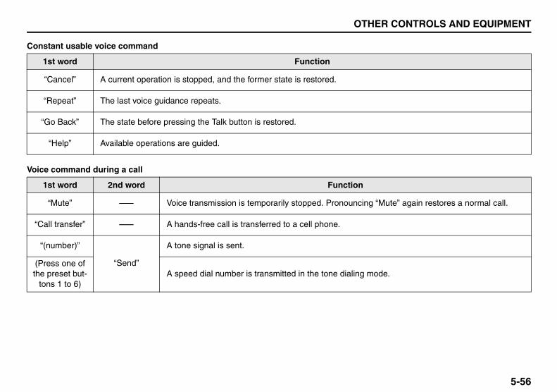
5-56
OTHER CONTROLS AND EQUIPMENT
57L20-03E
Constant usable voice command
Voice command during a call
1st word Function
“Cancel” A current operation is stopped, and the former state is restored.
“Repeat” The last voice guidance repeats.
“Go Back” The state before pressing the Talk button is restored.
“Help” Available operations are guided.
1st word 2nd word Function
“Mute” - Voice transmission is temporarily stopped. Pronouncing “Mute” again restores a normal call.
“Call transfer” - A hands-free call is transferred to a cell phone.
“(number)”
“Send”
A tone signal is sent.
(Press one of the preset but-
tons 1 to 6)A speed dial number is transmitted in the tone dialing mode.

5-57
OTHER CONTROLS AND EQUIPMENT
57L20-03E
Bluetooth® Hands-Free/Dialing
*1 Subsequently pronounce “Confirm” to implement the operation.
1st word 2nd word 3rd word Function
“(tag name)” “Dial” - Dialing the number of “(name)”
“Redial”
“Dial” - Dialing the corresponding number
“Store” - Adding the corresponding number to Phonebook*1
“Delete” - Deleting the corresponding number from the record*1
“Previous” - Back to the previous number
“Callback”
“Dial” - Dialing the corresponding number
“Store” - Adding the corresponding number to Phonebook*1
“Delete” - Deleting the corresponding number from the record*1
“Previous” - Back to the previous number
“Dial by number”“(phone num-
ber)”
“Dial” Dialing the number of “(phone number)”
“Delete” Canceling the number pronounced a moment ago
(Press the Off Hook button)
Dialing the number of “(phone number)”
“Dial by name”
“(tag name)”
“Dial” Dialing the number of “(tag name)”
(Press the Off Hook button)
Dialing the number of “(tag name)”
“List names”(Press the Talk
button)Dialing the number of the telephone that is read at that moment

5-58
OTHER CONTROLS AND EQUIPMENT
57L20-03E
Bluetooth® Hands-Free /Phone book
1st word 2nd word Function
“Phonebook, add entry”
“By voice”
Adding the number to Phonebook with voice1) Pronounce “(phone number)” and pronounce “Confirm” to confirm the operation.2) Pronounce “(tag name)”, and pronounce “Confirm” to confirm the operation.3) If the number is added to the speed dialing list, pronounce “Set speed dial” and
hold down one of the preset buttons 1 to 6 for 2 sec. or more. If the number is notadded to the speed dialing list, pronounce “Confirm” to confirm the operation.
“By phone”
Adding the number from the cell phone to Phonebook1) Make the cell phone ready for this operation, and pronounce “Confirm” to confirm
the operation.2) Pronounce “Previous” or “Next” to select a number, and pronounce “Confirm” to
confirm the selection.3) Pronounce “(tag name)” and pronounce “Confirm” to confirm the operation.4) If the number is added to the speed dialing list, pronounce “Set speed dial” and
hold down one of the preset buttons 1 to 6 for 2 sec. or more. If the number is notadded to the speed dialing list, pronounce “Confirm” to confirm the operation.
“Call history”
Adding the number from the record to Phonebook1) Pronounce “Incoming” to add the number from the incoming call record, and pro-
nounce “Outgoing” to add the number from the outgoing call record.2) Pronounce “Previous” or “Next” to select a number, and pronounce “Confirm” to
confirm the selection.3) Pronounce “(tag name)” and pronounce “Confirm” to confirm the operation.4) If the number is added to the speed dialing list, pronounce “Set speed dial” and
hold down one of the preset buttons 1 to 6 for 2 sec. or more. If the number is notadded to the speed dialing list, pronounce “Confirm” to confirm the operation.

5-59
OTHER CONTROLS AND EQUIPMENT
57L20-03E
*1 When “List phones” is pronounced, telephone names are read in sequence. When the corresponding telephone is read, press theTalk button.
*2 Subsequently pronounce “Confirm” to implement the operation.*3 When “List names” is pronounced, tag names are read in sequence. When the corresponding tag name is read, press the Talk button.
“Phonebook, change name”“(tag name)”*1
Changing the tag name of the number assigned to “(tag name)”*2
“Phonebook, delete entry” Deleting the number of “(tag name)” from Phonebook*2
“Phonebook, list names” (Press the Talk button) Dialing the number of the telephone that is read at that moment
“Phonebook, set speed dial” -
Registering the number in Phonebook on the speed dialing list1) Pronounce “(tag name)”*3 and “Confirm” to confirm the operation.2) Hold down one of the preset buttons 1 to 6 for 2 sec. or more and pro-
nounce “Confirm” to confirm the operation.
“Phonebook, delete speed dial”(Press one of the
preset buttons 1 to 6)Deleting the speed dial registered on the corresponding preset button*2
1st word 2nd word Function

5-60
OTHER CONTROLS AND EQUIPMENT
57L20-03E
*1 If a PIN number is not assigned, pronounce “Set PIN” and subsequently a 4-digit PIN number.
1st word 2nd word Function
“Phonebook”
“Phonebook lock”*1Phonebook is locked. To implement Phonebook locking, pronounce the PIN number andsubsequently “Confirm” to implement the locking.
“Phonebook unlock”Phonebook is unlocked. To implement Phonebook unlocking, pronounce the PIN numberand subsequently “Confirm” to implement the unlocking.
“Add entry” = “Phonebook, add entry”
“Change name” = “Phonebook, change name”
“Delete entry” = “Phonebook, delete entry”
“List names” = “Phonebook, list names”
“Set speed dial” = “Phonebook, set speed dial”
“Delete speed dial” = “Phonebook, delete speed dial”

5-61
OTHER CONTROLS AND EQUIPMENT
57L20-03E
Bluetooth® Hands-Free/Set up
*1 When “List phones” is pronounced, telephone names are read in sequence. When the corresponding telephone is read, press theTalk button.
1st word 2nd word 3rd word Function
“Set up” “Phone setup”
“Pair phone”
Telephone connection1) Pronounce “(phone name)” and “Confirm” to confirm the operation.2) Pronounce “Phone only” or “Internal audio” and subsequently “Confirm”
to confirm the operation.
“Select phone”Telephone selectionPronounce “(phone name)”*1 and “Confirm” to confirm the operation.
“Change name”Change of telephone name1) Pronounce “(phone name)”*1 and “Confirm” to confirm the operation.2) Pronounce “(new phone name)” and “Confirm” to confirm the operation.
“List phone”
Reading of telephone names in sequencePressing the Talk button during reading allows users to select the tele-phone that is read at the moment, and subsequently pronouncing “Selectphone”, “Change name”, or “Delete phone” allows users to implement eachcorresponding operation.
“Set passkey”Passkey settingPronounce “(4- to 8-digit number)” and “Confirm” to confirm the operation.
“Delete phone”Telephone deletionPronounce “(phone name)”*1 and “Confirm” to confirm the operation.
“Handsfree power”HF On/OffPronounce “Turn on” to enable HF and “Turn off” to disable HF.

5-62
OTHER CONTROLS AND EQUIPMENT
57L20-03E
Bluetooth® AudioNOTE:“Set up” is not available when no cell phone is registered. If audio device is registered and no cell phone is connected, you can use 3rdword in Bluetooth® audio mode.
*1 When “List audio players” is pronounced, audio device names are read in sequence. When the corresponding audio device name isread, press the Talk button.
1st word 2nd word 3rd word Function
“Set up”“Bluetooth® audio setup”
“Pair audio player”Audio device connectionPronounce “(audio device name)”*1 and “Confirm” to confirm the operation.
“Select audio player”
Audio device selection1) Pronounce “(audio device name)”*1 and “Confirm” to confirm the operation.2) Pronounce “From car” for connection from this unit or “From audio” for
connection from the audio device and subsequently “Confirm” to con-firm the operation.
“Change name”
Change of audio device name1) Pronounce “(audio device name)”*1 and “Confirm” to confirm the opera-
tion.2) Pronounce “(new audio device name)” and “Confirm” to confirm the
operation.
“List audio player”
Reading of audio device names in sequencePressing the Talk button during reading allows users to select the audiodevice that is read at the moment, and subsequently pronouncing “Selectaudio player”, “Change name”, or “Delete audio player” allows users toimplement each corresponding operation.
“Set Passkey”Passkey settingPronounce “(4- to 8-digit number)” and “Confirm” to confirm the operation.
“Delete audio player”Audio device deletionPronounce “(audio device name)”*1 and “Confirm” to confirm the operation.
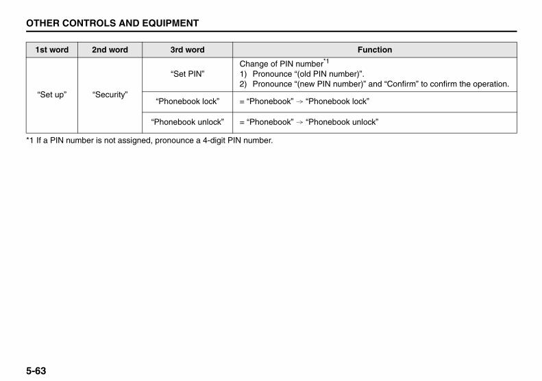
5-63
OTHER CONTROLS AND EQUIPMENT
57L20-03E
*1 If a PIN number is not assigned, pronounce a 4-digit PIN number.
1st word 2nd word 3rd word Function
“Set up” “Security”
“Set PIN”Change of PIN number*1
1) Pronounce “(old PIN number)”.2) Pronounce “(new PIN number)” and “Confirm” to confirm the operation.
“Phonebook lock” = “Phonebook” “Phonebook lock”
“Phonebook unlock” = “Phonebook” “Phonebook unlock”

5-64
OTHER CONTROLS AND EQUIPMENT
57L20-03E
Remote Audio ControlsYou can control basic functions of theaudio system with the switches on thesteering wheel.
Adjusting the volume• To increase the volume, lean the VOL
switch (1) to the upper side. The volumecontinues to increase until you releasethe switch.
• To decrease the volume, lean the VOLswitch (1) to the lower side. The volumecontinues to decrease until you releasethe switch.
• To mute, press the switch (2).
Selecting the modePress the switch (3).Each time the button is pressed, the modeis switched as follows:
You can also turn on the audio system bypushing the switch (3).
(2)
(1) (4)
(3)
FM1 (Radio)
FM2 (Radio)
CD
Bluetooth® audio
USB (iPod®)
AM (Radio)
XM1 (if equipped)
XM2 (if equipped)
XM3 (if equipped)

5-65
OTHER CONTROLS AND EQUIPMENT
57L20-03E
Selecting the radio station (FM1, FM2,AM mode)• To select the next preset station, lean
the SEEK switch (4) to the upper sidebriefly.
• To select the previous preset station,lean the SEEK switch (4) to the lowerside briefly.
• To scan to a higher frequency radio sta-tion, lean the SEEK switch (4) to theupper side for 1 sec. or longer.
• To scan to a lower frequency radio sta-tion, lean the SEEK switch (4) to thelower side for 1 sec. or longer.
Selecting the channel (XM1, XM2, XM3mode)• To select the next preset channel, lean
the SEEK switch (4) to the upper sidebriefly.
• To select the previous preset channel,lean the SEEK switch (4) to the lowerside briefly.
• To select the next channel in the samecategory, lean the SEEK switch (4) tothe upper side for 1 sec. or longer.
• To select the previous channel in thesame category, lean the SEEK switch(4) to the lower side for 1 sec. or longer.
Selecting the track (CD, USB (iPod®),Bluetooth® audio mode)• To advance to the next track, lean the
SEEK switch (4) to the upper sidebriefly.
• To select the previous track, lean theSEEK switch (4) to the lower side briefly.
Fast forwarding/Rewinding a track• To advance a track rapidly, lean the
SEEK switch (4) to the upper side for 1sec. or longer
• To rewind a track, lean the SEEK switch(4) to the lower side for 1 sec. or longer.

5-66
OTHER CONTROLS AND EQUIPMENT
57L20-03E
Anti-Theft Feature
TUNE / FOLDER / CH
DISP AS
RPT
XM USB
MENU
RDM
SEEK/ TRACK/CAT
SOUNDPUSH
1 2
3 4
5 6
VOL PUSH POWER
CDFM/ AM
H M
(2)(3)
(1) (4)
(1) VOL PUSH POWER knob(2) Preset buttons (1 to 6)(3) Up button(4) TUNE FOLDER PUSH SOUND knob

5-67
OTHER CONTROLS AND EQUIPMENT
57L20-03E
The anti-theft feature is intended to dis-courage theft or the audio system by pre-venting the system from operating when itis moved to a different vehicle.This feature works by allowing you to entera Personal Identification Number (PIN).When the audio system is disconnectedfrom its power source, such as when theaudio system is removed or the battery isdisconnected, the system will not operateagain unless the PIN is reentered.
Setting the Anti-Theft Function1) Press the VOL PUSH POWER knob
(1) to power off. 2) Press the Preset buttons (2) 1, 6 and
VOL PUSH POWER knob (1) simulta-neously.“SECURITY” is displayed.
3) Press the Up button (3) and Presetbutton (2) 1 simultaneously.
4) Enter a 4-digit PIN number using thePreset buttons (2) 1-4.
5) Hold down TUNE FOLDER PUSHSOUND knob (4) for 1 sec. or more.
NOTE:Write down your PIN for the future use.
Canceling the anti-theft featureThis operation is to be done when youwant to cancel the anti-theft function orchange your PIN.1) Press the Preset buttons (2) 1, 6 and
the VOL PUSH POWER knob (1)simultaneously.
2) Press the Up button (3) and Presetbutton (2) 1 simultaneously.
3) Enter a 4-digit PIN number using thePreset buttons (2) 1-4.
4) Hold down the TUNE FOLDER PUSHSOUND knob (4) for 1 sec. or more.
NOTE:To change your PIN, first delete your cur-rent PIN, then set a new one.
Confirming Your Personal IdentificationNumber (PIN)When the main power source is discon-nected such as when you exchange yourbattery, etc, you will have to confirm yourPIN to be able to use the audio system.1) Press the engine switch to change the
ignition mode to “ACC”.2) Press the Up button (3) and Preset
button (2) 1 simultaneously. 3) Enter a 4-digit PIN number using the
Preset buttons (2) 1-4. 4) Hold down the TUNE FOLDER PUSH
SOUND knob (4) for 1 sec. or more. If the PIN that you input matches theregistered PIN, the power of the audio-system will turn off, and you will beable to operate the audio system.
NOTE:If you input your PIN incorrectly, “ERROR”will be displayed. If you enter an incorrectPIN more than 10 times, “HELP” will bedisplayed and you can not perform anyfurther operation.

5-68
OTHER CONTROLS AND EQUIPMENT
57L20-03E
TroubleshootingIf you suspect something wrong, check and take steps as described below.If the described suggestions do not solve the problem, it is recommended to take the unit to your nearest dealer.
Problem Possible cause Possible solution
Common
Unable to operate The security function is on.
If the unit displays “SECURITY”, enteryour user ID.If the unit displays “HELP”, consult yourdealer.
Power is not turned on.(No sound is produced)
Fuse is blown. Contact your authorized SUZUKI dealer.
Radio
Much noiseThe unit is not exactly tuned in to the sta-tion.
Tune it in exactly to the station.
Unable to receive by auto tuningThere is no station emitting signals pow-erful enough.
Pick up a station by manual tuning.
XM
Channel unselectable No contact with XM Satellite radio Inc.Refer to the XM’s website to sign up forXM Radio service.
CD
Sound skipping or noise
The disc is dirty. Wipe the disc with a soft cloth.
The disc has a major flaw or is warped.Replace the disc with another withoutflaws.

5-69
OTHER CONTROLS AND EQUIPMENT
57L20-03E
MP3/WMA
No playback The disc has unplayable formatted data. Check the file format.
Sound skipping or noisePlaying VBR (Variable Bit Rate) files maycause sound skipping.
Play Non-VBR files.
USB
Music is not played back even if the USBdevice is connected
There is no music stored in a format thatis supported on this unit.
Check the file format.
The current consumption of the USBdevice exceeds 500 mA.
Use a USB device with a current con-sumption lower than 500 mA.
Bluetooth®
Pairing failed
The distance between this unit and theBluetooth®-ready device is too long, orthe Bluetooth®-ready device is hiddenbehind a metallic object from this unit.
Change the location of the Bluetooth®-ready device.
The Bluetooth® function of the Bluetooth®-ready device is deactivated.
Refer to the Operating Instructions of theBluetooth®-ready device. (With regard tosome devices, the power saving mode isactivated after a certain time.)
Cannot receive a call. Your mobile phone is out of service area.Drive your car to the service area of yourmobile phone.
The voice quality of hands-free is low(Distortion, noise etc.).
There is another wireless device near theunit.
Switch off the wireless device or keep itaway from the unit.
Problem Possible cause Possible solution

5-70
OTHER CONTROLS AND EQUIPMENT
57L20-03E
Error Display Messages
Display Possible cause Possible solution
XM
Ck Antenna XM antenna unconnected. Connect the XM antenna.
No SignalXM broadcasts unreceivable because ofpoor receiving conditions.
Move to an area where XM broadcasts can be receivedwell.
Ch Off Air Channel not in service.This channel is not currently in service. Tune to anotherchannel.
Ch Unavail Channel unavailable. This channel is out of service. Tune to another channel.
Ch Unauth Channel unauthorized. This channel is not authorized. Tune to another channel.

5-71
OTHER CONTROLS AND EQUIPMENT
57L20-03E
CD
ERROR 1 The disc cannot be read.
Insert the disc with its label side up.Check the disc that it is not warped and is free of flaws.If ERROR 1 does not go out when a normal disc isinserted, consult your dealer.
ERROR 3The player developed an error of an uni-dentified cause.
If CD is inserted in the unit, press the CD eject button toremove the disc.If the disc cannot be ejected, consult your dealer.
USB/iPod®
ERROR 1 No operation by some cause.Unplug the USB device and plug it again.If ERROR 1 does not go out when a normal disc isinserted, consult your dealer.
ERROR 3 The USB device is disconnected. Check the connection of the USB device.
ERROR 4The current consumption of the USBdevice exceeds 500 mA.
Check the USB device.
Display Possible cause Possible solution

5-72
OTHER CONTROLS AND EQUIPMENT
57L20-03E
Bluetooth®
ERROR 1The player developed an error of an uni-dentified cause.
Disconnect the Bluetooth®-ready device and connect itagain.If ERROR 1 does not go out, consult your dealer.
Failed Failed to establish pairing Try to establish the pairing again.
Memory FullReaching the upper limit of the register-able device count
Delete the registered data of unnecessary devices andtry to establish the pairing again.
Not Avail. Inoperable during driving Operate the system after pulling over your car.
Pardon? Failed voice recognition Press the Talk button and say what you said again.
Not Linked Telephone disconnected Try to establish the pairing again.
Display Possible cause Possible solution
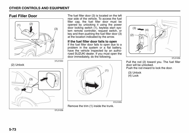
5-73
OTHER CONTROLS AND EQUIPMENT
57L20-03E
Fuel Filler Door
57L51054
(2) Unlock
57L51058
The fuel filler door (3) is located on the leftrear side of the vehicle. To access the fuelfiller cap, the fuel filler door must beopened by unlocking it using the powerdoor locking switch (1), keyless start sys-tem remote controller, request switch, orkey and then pushing the fuel filler door (3)at the location indicated by the arrow.
If the fuel filler door fails to openIf the fuel filler door fails to open due to aproblem in the system or a flat battery,have the vehicle inspected by an autho-rized SUZUKI dealer. If you must open thedoor immediately, do the following.
57L51055
Remove the trim (1) inside the trunk.
57L51056
Pull the rod (2) toward you. The fuel fillerdoor will be unlocked.Push the rod inward to lock the door.
(3) Unlock(4) Lock
(1)(3)
(2)
(3)
(1)
(2)
(3)(4)

5-74
OTHER CONTROLS AND EQUIPMENT
57L20-03E
57L51057
From the outside, push the part indicatedby the arrow of the fuel filler door (5) (seethe illustration). The door will open slightly.
Fuel Filler Cap
79K053
To remove the fuel filler cap:1) Open the fuel filler door.2) Remove the cap by turning it counter-
clockwise.
57L51019
NOTE:The cap holder (1) can hold the fuel fillercap (2) when refueling.
To reinstall the fuel filler cap:1) Turn the cap clockwise until you hear
several clicks.2) Close the fuel filler door.
(5)
WARNINGRemove the fuel filler cap slowly. Thefuel may be under pressure and mayspray out, causing injury.
Open Close
EXAMPLE
WARNINGFuel is extremely flammable. Do notsmoke when refueling, and makesure there are no open flames orsparks in the area.
(1) (2)

5-75
OTHER CONTROLS AND EQUIPMENT
57L20-03E
Engine Hood
57L51020
To open the engine hood:1) Pull the hood release handle (1)
located on the outboard side of thedriver’s side of the instrument panel.This will disengage the engine hoodlock halfway.
57L51066
2) Push the under-hood release lever (2)sideways with your finger, as shown inthe illustration. While pushing the lever,lift up the engine hood.
WARNING• Avoid spilling fuel. Any spilt fuel
must be wiped clean with a softcloth. Leaving the fuel as is couldlead to a fire or other unexpectedaccident. Fuel will also causespots, discoloration or cracks onthe paintwork in the area.
• Close the fuel filler cap firmly afterrefueling. A loose cap may causefuel leakage and eventually a fire.
• If you need to replace the fuel cap,use a genuine SUZUKI cap. Use ofan improper cap can result in amalfunction of the fuel system oremission control system. It mayalso result in fuel leakage in theevent of an accident.
(1)
(2)

5-76
OTHER CONTROLS AND EQUIPMENT
57L20-03E
57L50015
3) Continue to lift up the hood until it ishigh enough to support with the proprod (3).
To close the engine hood:1) Lift the hood up slightly and remove the
prop rod from the hole (5). Put the proprod back to the holding clip (4).
2) Lower the hood close to the bumper,then let it drop down. Make sure thehood is securely latched after closing.
(4)
(3)
(5)
WARNINGMake sure the hood is fully closedand latched before driving. If it is not,it can fly up unexpectedly duringdriving, obstructing your view andresulting in an accident.

5-77
OTHER CONTROLS AND EQUIPMENT
57L20-03E
Sun Visor
57L50032
(1) Hook(2) Vanity mirror cover(3) Ticket holder(4) Extension
The sun visors can be pulled down to blockglare coming through the windshield, orthey can be unhooked and turned to theside to block glare coming through the sidewindow.
The extension (4) can be drawn out toblock glare widely.
Both the driver’s and passenger’s sunvisors have a ticket holder on the side fac-ing the interior when they are pulled down.The ticket holder is on the vanity mirrorcover.
(1) (2)
(3) (4)
CAUTIONWhen unhooking and hooking a sunvisor, be sure to handle it by the hardplastic parts or the sun visor can bedamaged.
CAUTIONDo not leave cards or similar plasticobjects in the ticket holder whenparking under the sun. The cabintemperature may rise high enough tocause the plastic objects to crack ordeform.

5-78
OTHER CONTROLS AND EQUIPMENT
57L20-03E
Interior Light SwitchFront
57L51021
Rear
57L51022
The interior light switch has three posi-tions, which functions as described below.
ON (1)The light comes on and stays on regard-less of whether the door is open or closed.
DOOR (2)The light comes on when the door isopened. After closing all doors, the lightwill remain on for about 15 seconds andthen fade out. If you press the engineswitch to change the ignition mode to“ACC” or “ON” during this time, the light willstart to fade out immediately. If you changethe ignition mode to “LOCK” (OFF) bypressing the engine switch, the light willremain on for about 15 seconds and thengo out.
OFF (3)The light remains off even when the door isopened.
NOTE:If the rear interior light switch is set to“DOOR”, the light is turned on or off at thesame time the front interior light is turnedon or off.
79J075
NOTE:The number of doors involved in the light-ing operation of the interior light dependson the vehicle specification. If there is aswitch (rubber projection) at the dooropening as shown, the door is involved inthe lighting operation. The trunk lid is notinvolved in this operation.
(2)(1)(3)
(1)(3)(2)
EXAMPLE

5-79
OTHER CONTROLS AND EQUIPMENT
57L20-03E
Courtesy Lights
57L51023
Each front door has a courtesy light (1) onits inside bottom. It lights automaticallywhen the door is opened.
Footwell Lights
57L51024
A footwell light is provided in the leg spacein front of each front seat. When a frontdoor is opened, the footwell light on thesame side lights automatically.
Trunk Light
57L50019
When you open the trunk lid, the trunk lightcomes on and remains on as long as youkeep the lid open.
(1)
CAUTIONDo not leave the trunk lid open for along time, or the battery will dis-charge.
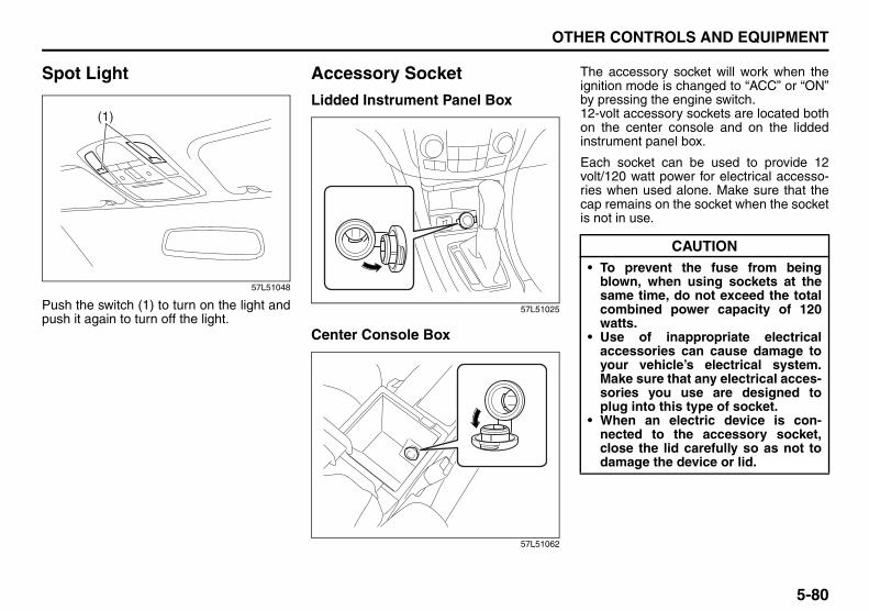
5-80
OTHER CONTROLS AND EQUIPMENT
57L20-03E
Spot Light
57L51048
Push the switch (1) to turn on the light andpush it again to turn off the light.
Accessory SocketLidded Instrument Panel Box
57L51025
Center Console Box
57L51062
The accessory socket will work when theignition mode is changed to “ACC” or “ON”by pressing the engine switch.12-volt accessory sockets are located bothon the center console and on the liddedinstrument panel box.
Each socket can be used to provide 12volt/120 watt power for electrical accesso-ries when used alone. Make sure that thecap remains on the socket when the socketis not in use.
(1)
CAUTION• To prevent the fuse from being
blown, when using sockets at thesame time, do not exceed the totalcombined power capacity of 120watts.
• Use of inappropriate electricalaccessories can cause damage toyour vehicle’s electrical system.Make sure that any electrical acces-sories you use are designed toplug into this type of socket.
• When an electric device is con-nected to the accessory socket,close the lid carefully so as not todamage the device or lid.

5-81
OTHER CONTROLS AND EQUIPMENT
57L20-03E
Universal Serial Bus (USB) Socket
57L51061
Connect your portable digital music player,etc. to this socket to enjoy music throughthe vehicle’s audio system using it as asource. Refer to “Audio Systems” in the“OTHER CONTROL AND EQUIPMENT”section.
Cigarette Lighter (if equipped)
57L51068
The cigarette lighter will work when youpress the engine switch to change the igni-tion mode to “ACC” or “ON”.
To use the cigarette lighter, push it all theway into the receptacle and release it. Itwill automatically heat up and will pop outto its normal position when it is ready foruse.CAUTION
If you close the lid of the liddedinstrument panel box with a devicestill connected to the USB socket, theequipment and the socket may bedamaged.
CAUTIONHolding the cigarette lighter in canoverheat and damage the lighter.Release the lighter after you push itin.
CAUTIONTo avoid damage to the cigarettelighter socket, do not use it as anaccessory power source. Someaccessories’ power plug can damagethe inner mechanism of the cigarettelighter socket.

5-82
OTHER CONTROLS AND EQUIPMENT
57L20-03E
Ashtray (if equipped)
79J047
You can fit the ashtray into any of the cupholders on the center console.
57L51065
Assist Grips
54G249
Assist grips are provided for convenience.
WARNINGMake sure tobacco is fully extin-guished before closing the ashtrays.Never throw waste in the ashtrays: itcould create a fire hazard.
CAUTIONWhen fitting the ashtray into a cupholder on the center console, orient itas shown in the illustration. Doingotherwise may damage the ashtrayand/or the center console.
CAUTIONTo avoid damaging the assist gripand the molded roof lining, do nothang down the assist grip.

5-83
OTHER CONTROLS AND EQUIPMENT
57L20-03E
Coat Hooks
57L51049
You can hang clothing on the coat hooks.These hooks are not designed for large orheavy items.
Sunroof (if equipped)You can tilt or slide the sunroof by operat-ing the “TILT” part of the sunroof switch orthe “SLIDE” part of the sunroof switch afterpressing the engine switch to change theignition mode to “ON”.
There is a system to prevent being pinchedby the sunroof.When the system senses that something ispinched when the sunroof is sliding for-ward, the sunroof will automatically reversedirection and slide rearward. This systemwill operate when the sunroof is closingautomatically. This system does not oper-ate when tilting the sunroof down.
Make sure there are no hands or otherobstructions in the path of the sunroofwhen you close the sunroof even thoughthere is a system to prevent being pinchedby the sunroof.
57L51026
To tilt the sunroof up, slide the sun shaderearward by hand and push the “TILT UP”part (1) of the sunroof switch. To tilt thesunroof down, push the “SLIDE OPEN”part (2) of the sunroof switch.If you push the switch for more than a sec-ond, the sunroof will automatically tilt up ordown fully. To stop the sunroof halfway,push the switch briefly.
WARNINGYour vehicle is equipped with sidecurtain air bags, do not hang sharpitems like a hanger on the coat hook.When hanging the clothes, hang it onhook without using a hanger.
WARNING• The system to prevent being
pinched by the sunroof does notwork in the area where the sunroofis almost completely closed.
• The system to prevent beingpinched by the sunroof may notwork if the battery is not suffi-ciently charged.
(2)
(1)

5-84
OTHER CONTROLS AND EQUIPMENT
57L20-03E
57L51027
To slide the sunroof rearward, push the“SLIDE OPEN” part (2) of the sunroofswitch. To slide the sunroof forward, pushthe “TILT UP” part (1) of the sunroofswitch.If you push the switch for more than a sec-ond, the sunroof will automatically slidefully rearward or forward. To stop the sun-roof halfway, push the switch briefly.
57L51028
The sun shade will open manually andcannot be closed when the sunroof is slidrearward.
How to reactivate the system to preventbeing pinched by the sunroofWhen you disconnect the negative (–) ter-minal from the battery or change the fuses,the features below will not operate.• The system to prevent being pinched by
the sliding sunroof.• The system to automatically open or
close the sunroof fully.
In this case, you must reactivate the fea-tures using the following procedures.1) Press the engine switch to change the
ignition mode to “ON”.2) Push and hold the “TILT UP” part (1) of
the sunroof switch, the sunroof will tiltup fully and then down slightly. After themovement stops completely, releasethe switch. The features are reacti-vated.
3) Make sure you can open or close thesunroof automatically by pushing thesunroof switch for more than about asecond.
(2)
(1)

5-85
OTHER CONTROLS AND EQUIPMENT
57L20-03E
65D612
• Be sure to close the sunroof when youleave the vehicle unattended.
• Periodically inspect the guide rail for dirtand clean it if any dirt has accumulated.
Glove Box
57L51029
(2) Unlock(3) Lock
To open the glove box, pull the latch lever(1). To close it, push the lid until it latchessecurely.To lock the glove box, insert the keyattached to your keyless start systemremote controller into the lock, turn the keyfully clockwise, and pull it out of the lock inthis position.
WARNING• Never allow any part of your body
such as hands or head to get out ofthe sunroof opening while the vehi-cle is moving.
• Be sure there are no hands or otherobstructions in the path of the sun-roof when you close the sunroof.
• Always take the keyless start sys-tem remote controller with youwhen leaving the vehicle even ifonly for a short time. Also do notleave children alone in a parkedvehicle. Unattended children coulduse the sunroof switches and gettrapped by the sunroof.
CAUTIONDo not put your body weight on theroof around the sunroof such as bysitting on it.
WARNINGNever drive with the glove box lidopen. It could cause injury if an acci-dent occurs.
(1)
(3)(2)

5-86
OTHER CONTROLS AND EQUIPMENT
57L20-03E
57L51030
The glove box light stays on while the lid isopen.
Overhead Console
57L51031
Use this stowage to keep small articles.You can open the lid (1) by pressing theraised portion on it.
(1)
CAUTION• Do not drive with the overhead con-
sole lid open, or the articles stowedinside could fall down during brak-ing, acceleration or in the event of acollision. Always close the lid afterputting something into or takingsomething out of the console.
• If you park your vehicle outdoors indirect sunlight or in hot weather,the overhead console can get veryhot since it is close to the roof. So,when parking in such conditions:– Do not leave eyeglasses in the
overhead console. The heat maydistort plastic lenses or frames.
– Do not place flammable items,such as a lighter, in the overheadconsole. The heat may cause afire.
• Do not apply undue force to the lidwhen closing it. Doing so couldbreak the lid and articles inside.
• Place glasses in a case when stow-ing them in the overhead console,or the lenses may be damaged.

5-87
OTHER CONTROLS AND EQUIPMENT
57L20-03E
Lidded Instrument Panel Box
57L51032
Use this stowage to keep small articles.You can open the lid (1) by pressing theraised portion on it.
Cup Holder and Storage Area (if equipped)
57L51069
Cup holders (1) are provided in the centerconsole.You can open the lid (2) by pressing theraised portion on it.
57L51046
The cup holder (1) for rear seat passen-gers is extended ready for use when thearmrest is tilted down and the button (2) ispressed. Push the cup holder backward tostore it.
WARNINGNever drive with the lid of the liddedinstrument panel box open. It couldcause injury if an accident occurs.
(1)
(1)(2) (2)(1)

5-88
OTHER CONTROLS AND EQUIPMENT
57L20-03E
Bottle holderFront
57L50041
(1) Bottle holder
Rear
57L50042
(1) Bottle holder
You should hold a bottle with a cap in theholder.WARNING
Do not use the cup holder or the stor-age bin to hold cups containing hotliquids or sharp-edged, hard orbreakable objects. Objects in thesebins may be thrown about during asudden stop or impact, and couldcause personal injury. If a drink is spilled over the audiosystem (if equipped) or electricswitches, or if a spilled drink reachesthe under-floor wiring or electriccomponents, it could cause the sys-tem to malfunction or even a fire, andimpair normal operation of the SRSair bag system.
(1)
(1)
WARNINGPrevent drink from spilling by cap-ping the bottle as necessary.If a hot drink is spilled, you may bescalded.If a drink is spilled over the audiosystem (if equipped) or electricswitches, or if a spilled drink reachesthe under-floor wiring or electriccomponents, it could cause the sys-tem to malfunction or even a fire, andimpair normal operation of the SRSair bag system.

5-89
OTHER CONTROLS AND EQUIPMENT
57L20-03E
Front Seat Back Pocket (if equipped)
57L50043
(1) Front seat back pocket
This pocket is provided for holding lightand soft things such as gloves, newspa-pers or magazines.
Footrest
57L51033
Use the footrest (1) as a support for yourleft foot.
Center Console BoxUse this stowage for keeping small arti-cles.The box consists of upper and lower com-partments. The upper compartment formsa tray, which also serves as a lid of thelower compartment.
Upper compartmentOpen the upper compartment by raisingthe top lid (2) while keeping the lever (1)up.
57L50045
WARNINGDo not put hard or breakable objectsin the pocket. If an accident occurs,objects such as bottles, cans, etc.can injure the occupants in the rearseat.
(1)
(1)
(2)
(1)

5-90
OTHER CONTROLS AND EQUIPMENT
57L20-03E
Lower compartmentOpen the lower compartment by raisingthe top lid and tray (4) together while keep-ing the lever (3) up.
57L51035
NOTE:• Always close the lid after you put some-
thing into or take something out of thebox.
• The upper compartment (tray) and lowercompartment have slots on their edgesso that the cable of an appliance con-nected to the accessory socket can beled through them. When the top lid or thetop lid and tray combination is raised orlowered to open or close the upper orlower compartment, be careful not totrap a cable under it.
ArmrestFront
57L50069
The lid of the center console box serves asthe front armrest when it is closed.
Rear
57L51047
The armrest (1) is stowed in the center ofthe seatback. Tilt it down forward to use.
57L50070
(4)
(3)
(1)
(1)
WARNING• The seat belt must always be
passed under the armrest. It cannotprovide the intended protection if itruns over the armrest.
• In an accident or sudden stop, therear armrest could fall forward. Ifthere is a child in a rearfacing childrestraint in the center seating posi-tion, the falling armrest could injurethe child. Make sure the armrest issecured in the stowed positionwhen not in use.
(1)
(2)

5-91
OTHER CONTROLS AND EQUIPMENT
57L20-03E
NOTE:There is a lid (1) behind the armrest stow-age in the seatback.• When carrying a long cargo, the lid (1)
can be opened by folding it forward whilekeeping the lever (2) pressed down.
• When closing the lid (1), raise and pushit into position.
Floor Mats (if equipped)
57L51063
(1) UNLOCK(2) LOCK
Both driver-side and passenger-side floormats are retained with fasteners to preventthem from sliding forward and possiblyinterfering with the pedals. Whenever youput the mats back after removing them,correctly position and secure the mats bypassing the fastener knob through eachhole in the mats and turning it to the lockposition as shown in the illustration so thatthe mats will neatly fit under your feet andthe passenger’s feet.
When you replace the floor mats in yourvehicle with a different type such as all-weather floor mats, we highly recommendusing genuine SUZUKI floor mats forproper fitting.
(1)
(2)
WARNINGFailure to take the following precau-tions may result in the driver’s sidefloor mat interfering with the pedalsand causing a loss of vehicle controlor an accident.• Make sure that all fastener knobs
are in their holes in the floor matsand correctly locked.
• Never place additional floor matson top of the existing floor mats.

5-92
OTHER CONTROLS AND EQUIPMENT
57L20-03E
Luggage Under-boxUse this stowage for carrying small bag-gage or the like.• To access the stowage, raise the floor-
board by holding the handle (1) on it andhang the hook (2) on the edge of thetrunk.
57L51050
Net/Rope Hooks
57L50049
There are two net hooks (1), one on eachof the trunk opening sides.There are four rope hooks (2) provided onthe trunk floor.Pull out these hooks to use as shown inthe illustration.An optional rubber net can be hooked tothese hooks to help keep cargo from mov-ing around in the luggage compartmentduring normal driving.
Roof Rack Anchors (if equipped)
80J082
You can use the roof rack anchors toattach the optional roof rack which is avail-able at your SUZUKI dealer. If you use aroof rack, observe the instructions and pre-cautions in this section and provided withthe roof rack.
• Make sure the roof rack is securelyinstalled.
• To mount various types of cargo (suchas skis, bicycles, etc.) properly, use suit-able attachments which are availablefrom your SUZUKI dealer. Be sure toinstall the attachments properly andsecurely according to the instructionsprovided. Do not mount cargo directly onthe roof panel. The cargo can damagethe roof panel.
(1)
(2)(2)
CAUTIONUse the net and rope hooks only forholding light objects.
(2)(1)

5-93
OTHER CONTROLS AND EQUIPMENT
57L20-03E
• The gross weight of the roof rack pluscargo must not exceed the loadingcapacity (50 kg (110 lbs)). Also, do notlet the gross vehicle weight (fully loadedvehicle including driver, passengers,cargo, roof load and trailer tongueweight) exceed the Gross VehicleWeight Rating (GVWR) listed in thedriver’s door lock pillar.
• Mount and secure the cargo onto theroof rack properly according to theinstructions provided. Be sure to stowthe heaviest items at the bottom and dis-tribute the cargo as evenly as possible.
• Do not carry items so large that theyhang over the bumpers or the sides ofthe vehicle, or block your view.
• Secure the front and rear ends of longitems – such as wood panels, surfboardsand so forth – to both the front and rearof the vehicle. You should protect thepainted surfaces of the vehicle fromscuffing caused by tie-down ropes.
• Check periodically to make sure the roofrack is securely installed and free fromdamage.
• For vehicles with roof rack anchors,make sure the anchors are covered withthe caps when not in use.
HomeLink® (if equipped)
66J092
HomeLink®: HomeLink® is a registeredtrademark of Johnson Controls TechnologyCompany.
The HomeLink® Wireless Control Systemprovides a convenient way to replace up tothree hand-held radio-frequency (RF)transmitters used to activate devices suchas gate operators, garage door openers,entry door locks, security systems, evenhome lighting. Additional HomeLink® infor-mation can be found on the Internet atwww.homelink.com or by calling 1-800-355-3515.
Before programming HomeLink® to agarage door opener or gate operator, makesure that people and objects are out of theway of the device to prevent potential harmor damage. When programming a garagedoor opener, it is advised to park outside ofthe garage. Do not use HomeLink® withany garage door opener that lacks safetystop and reverse features as required byU.S. federal safety standards (this includes
WARNING• Abrupt maneuvers or failure to
properly secure cargo can allow thecargo to fly off the vehicle and hitothers, causing personal injury orproperty damage.
• Mount cargo securely and avoidabrupt maneuvers such as “jack-rabbit” starts, sharp turns, fast cor-nering and sudden braking. Checkperiodically to make sure thatcargo is securely fastened.
• Large, bulky, long, or flat items canaffect vehicle aerodynamics or becaught by the wind, and can reducevehicle control resulting in an acci-dent and personal injury. Drive cau-tiously at a safely reduced speedwhen carrying this type of cargo.

5-94
OTHER CONTROLS AND EQUIPMENT
57L20-03E
any garage door opener position manufac-tured before April 1, 1982). A garage doorthat cannot detect an object – signaling thedoor to stop and reverse – does not meetcurrent U.S. federal safety standards. Formore information, contact HomeLink® atwww.homelink.com or by calling 1-800-355-3515.
Retain the original transmitter of the RFdevice you are programming for use inother vehicles as well as for futureHomeLink® programming. It is also sug-gested that upon the sale of the vehicle,the programmed HomeLink® buttons beerased for security purposes. Refer to“Programming HomeLink®” (step 1) only)or, for assistance, contact HomeLink® atwww.homelink.com or by calling 1-800-355-3515.
Programming HomeLink®
NOTE:Some vehicles may require the ignitionswitch to be turned to the second (or“accessories”) position or the “on” positionfor programming and/or operation ofHomeLink®. It is also recommended that anew battery be placed in the hand-heldtransmitter of the device being pro-grammed to HomeLink® for quicker train-ing and accurate transmission of theradiofrequency signal. Do not repeat “Pro-gramming HomeLink®” – step 1) to trainadditional devices to a second or third
HomeLink® button. Begin with “Program-ming HomeLink®” – step 2).
57L51036
1) Press and hold the two outerHomeLink® buttons (buttons one andthree) – releasing only when the indica-tor light begins to flash (after 20 sec-onds). Do not hold the buttons forlonger than 30 seconds and do notrepeat step 1) to program a secondand/or third hand-held transmitter to theremaining two HomeLink® buttons.
2) Position the end of your hand-heldtransmitter 5–14 cm (1–3 inches) awayfrom the HomeLink® button you wish toprogram while keeping the indicatorlight in view.
3) Simultaneously press and hold both thechosen HomeLink® and hand-heldtransmitter buttons. Do not release thebuttons until step 4) has been com-pleted.
NOTE:Some gate operators and garage dooropeners may require you to replace thisProgramming step 3) with proceduresnoted in the “Gate Operator / CanadianProgramming” section.
4) After the HomeLink® indicator lightchanges from a slow to a rapidly blink-ing light, release both the HomeLink®
and hand-held transmitter buttons.
NOTE:If the HomeLink® indicator light does notchange to a rapidly blinking light, contactHomeLink® at www.homelink.com or call1-800-355-3515 for assistance.
5) Press and hold the just-trainedHomeLink® button and observe theindicator light.
– If the indicator light stays on con-stantly, programming is complete andyour device should activate when theHomeLink® button is pressed andreleased.
NOTE:To program the remaining two HomeLink®
buttons, begin with “ProgrammingHomeLink®” – step 2). Do not repeat step1).
– If the indicator light blinks rapidly fortwo seconds and then turns to a con-stant light continue with “Programming

5-95
OTHER CONTROLS AND EQUIPMENT
57L20-03E
HomeLink®” steps 6–8 to complete theprogramming of a rolling codeequipped device (most commonly agarage door opener).
66J051
66J052
6) At the garage door opener receiver(motor-head unit) in the garage, locatethe “learn” or “smart” button. This canusually be found where the hangingantenna wire is attached to the motor-head unit.
7) Firmly press and release the “learn” or“smart” button. (The name and color ofthe button may vary by manufacturer.)
NOTE:There are 30 seconds in which to initiatestep 8).
8) Return to the vehicle and firmly press,hold for two seconds and release theprogrammed HomeLink® button.Repeat the “press/hold/release”sequence a second time, and, depend-ing on the brand of the garage dooropener (or other rolling code equippeddevice), repeat this sequence a thirdtime to complete the programming pro-cess. HomeLink® should now activate yourrolling code equipped device.
NOTE:To program the remaining two HomeLink®
buttons, begin with “ProgrammingHomeLink®” – step 2). Do not repeat step1).
For questions or comments, please con-tact HomeLink® at www.homelink.com or1-800-355-3515.
Gate Operator / Canadian Program-mingCanadian radio-frequency laws requiretransmitter signals to “time-out” (or quit)after several seconds of transmission –which may not be long enough forHomeLink® to pick up the signal duringprogramming. Similar to this Canadian law,some U.S. gate operators are designed to“time-out” in the same manner.
If you live in Canada or you are having diffi-culties programming a gate operator byusing the Programming procedures(regardless of where you live), replace“Programming HomeLink®” step 3) withthe following:
NOTE:If programming a garage door opener orgate operator, it is advised to unplug thedevice during the “cycling” process to pre-vent possible overheating.
3) Continue to press and hold theHomeLink® button while you press andrelease – every two seconds (“cycle”)your hand-held transmitter until the fre-quency signal has successfully beenaccepted by HomeLink®. (The indicatorlight will flash slowly and then rapidly.)
Proceed with “Programming HomeLink®”step 4) to complete.

5-96
OTHER CONTROLS AND EQUIPMENT
57L20-03E
Using HomeLink®
To operate, simply press and release theprogrammed HomeLink® button. Activationwill now occur for the trained device (i.e.garage door opener, gate operator, secu-rity system, entry door lock, home/officelighting, etc.). For convenience, the hand-held transmitter of the device may also beused at any time. In the event that thereare still programming difficulties or ques-tions, contact HomeLink® atwww.homelink.com or 1-800-355-3515.
Erasing HomeLink® ButtonsTo erase programming from the three but-tons (individual buttons cannot be erasedbut can be “reprogrammed” as outlinedbelow), follow the step noted:
Press and hold the two outer HomeLink®
buttons until the indicator light begins toflash-after 20 seconds. Release both but-tons. Do not hold for longer that 30 sec-onds. HomeLink® is now in the train (orlearning) mode and can be programmed atany time beginning with “ProgrammingHomeLink®” – step 2).
Reprogramming a Single HomeLink® ButtonTo program a device to HomeLink® using aHomeLink® button previously trained, fol-low these steps:
1) Press and hold the desired HomeLink®
button. DO NOT release the button.2) The indicator light will begin to flash
after 20 seconds. Without releasing theHomeLink® button, proceed with “Pro-gramming HomeLink®” – step 2).
For questions or comments, contactHomeLink® at www.homelink.com or 1-800-355-3515.
Frame HooksFront hook (1)1) Take out the necessary tools (jack bar,
wheel nut wrench and tow hook) fromthe onboard tool set.
2) Use the end of the jack bar (a) wrappedwith a cloth (b) to open the front towhook cover (c).
57L51037
3) Insert the tow hook (e) into the towhook receptacle (d) and screw the hookin as far as it can be turned by hand.
(c)(a)
(b)
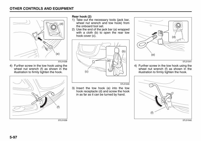
5-97
OTHER CONTROLS AND EQUIPMENT
57L20-03E
57L51038
4) Further screw in the tow hook using thewheel nut wrench (f) as shown in theillustration to firmly tighten the hook.
57L51039
Rear hook (2)1) Take out the necessary tools (jack bar,
wheel nut wrench and tow hook) fromthe onboard tool set.
2) Use the end of the jack bar (a) wrappedwith a cloth (b) to open the rear towhook cover (c).
57L51040
3) Insert the tow hook (e) into the towhook receptacle (d) and screw the hookin as far as it can be turned by hand.
57L51041
4) Further screw in the tow hook using thewheel nut wrench (f) as shown in theillustration to firmly tighten the hook.
57L51042
(d)
(e)
(f)
(a)
(c)
(b)
(d)
(e)
(f)

5-98
OTHER CONTROLS AND EQUIPMENT
57L20-03E
Side (3)
57L51043
57L51044
57L51045
Frame hooks are provided on the front (1),rear (2) and side (3) of the vehicle. Thehooks (1) and (2) are used for emergencysituations. The hooks (3) are used fortrailer/train shipping purposes.The hook (4) is used for transportation byship.
To tow your vehicle on the road or highway,follow the instruction of “Towing” in “EMER-GENCY SERVICE” section.
(3)
Front
(3)
Rear
(4)
WARNINGDo not use the frame hooks to towanother vehicle or to have your vehi-cle towed on the road or highway.The hooks (1) and (2) are designedfor use in emergency situations only,such as if your vehicle or anothervehicle gets stuck in deep mud orsnow.The hooks (3) are provided for trailer/train shipping purpose.The hook (4) is provided for transpor-tation by ship.
CAUTIONNever use the hooks (1) and (2) fortransporting the vehicle by a trailer,train or ship, as doing so may dam-age the vehicle.

5-99
OTHER CONTROLS AND EQUIPMENT
57L20-03E
MEMO

VEHICLE LOADING AND TOWING
6
57L20-03E
54G215
VEHICLE LOADING AND TOWINGVehicle Loading ................................................................... 6-1Trailer Towing ...................................................................... 6-2Towing Your Vehicle (recreational towing) ...................... 6-2

6-1
VEHICLE LOADING AND TOWING
57L20-03E
Vehicle Loading
57L61001
Your vehicle was designed for specificweight capacities. The weight capacities ofyour vehicle are indicated by the GrossVehicle Weight Rating (GVWR), the GrossAxle Weight Rating (GAWR, front and rear)and the Vehicle Capacity Weight. TheGVWR and GAWR (front and rear) arelisted on the Safety Certification Labelwhich is located below the driver’s sidedoor latch striker. The Vehicle CapacityWeight is listed on the Tire InformationLabel which is located below the SafetyCertification Label.
GVWR – Maximum permissible overallweight of the fully loaded vehicle (includingall the occupants, accessories and cargo).GAWR – (Front and Rear) Maximum per-missible weight on an individual axle.
Vehicle Capacity Weight – Maximum per-missible load weight a vehicle can carryincluding the weight of all the occupants,accessories and cargo.
The weight of any accessories alreadyinstalled on your vehicle at the time of pur-chase, or that you or the dealer install afterpurchase, must be subtracted from theVehicle Capacity Weight to determine howmuch capacity remains available for occu-pants and cargo. Contact your dealer forfurther information.
Actual weight of the loaded vehicle andactual loads at the front and rear axles canonly be determined by weighing the vehicleusing a vehicle scale. To measure theweight and load, try taking your vehicle toa highway weighing station, shipping com-pany or inspection station for trucks, etc.Compare these weights to the GVWR andGAWR (front and rear) listed on the SafetyCertification Label. If the gross vehicleweight or the load on either axle exceedsthese ratings, you must remove enoughweight to bring the load down to the ratedcapacity.
WARNINGNever overload your vehicle. Thegross vehicle weight (sum of theweights of the loaded vehicle, driverand passengers) must never exceedthe Gross Vehicle Weight Rating(GVWR) listed on the Safety Certifica-tion Label. In addition, never distrib-ute a load so that the weight on eitherthe front or rear axle exceeds theGross Axle Weight Rating (GAWR)listed on the Safety CertificationLabel.
WARNING• Always distribute cargo evenly.• To avoid personal injury or damage
to your vehicle, always securecargo to prevent it from shifting ifthe vehicle moves suddenly.
• Place heavier objects on the floorand as far forward in the trunk or inthe cargo area as possible.
• Never pile cargo higher than thetop of the seat backs.
Exhaust Gas Warning: NODaily Inspection Checklist: NO

6-2
VEHICLE LOADING AND TOWING
57L20-03E
Trailer Towing
54G639
Do not use your vehicle to tow a trailer. Thevehicle is not designed or intended forsuch use. Towing a trailer can adverselyaffect handling, durability and fuel econ-omy.
Towing Your Vehicle (recreational towing)Your vehicle may be towed behind anothervehicle (such as a motorhome), providedyou use the proper towing method speci-fied for your vehicle. The towing methodyou must use depends on the specifica-tions of your vehicle: whether it is a 2-wheel drive (2WD) or intelligent All WheelDrive (i-AWD) vehicle.
Use the towing instruction table to selectthe proper towing method for your vehicle,and carefully follow the correspondinginstructions. Be sure to use proper towingequipment designed for recreational tow-ing and make sure that towing speed doesnot exceed 90 km/h (55 mph).
TOWING INSTRUCTION TABLE
80J2051
WARNINGAlways use a safety chain when tow-ing your vehicle and be sure toobserve federal, state, and localrequirements for trailer hitches, towbars, lights, etc.
DRIVE TRAIN TRANSAXLE TOWING
METHOD
2WDCVT (AUTO) A
M/T (MANUAL) A Bi-AWDinclud-
ing 2WD mode
CVT none
CAUTIONFor the CVT of intelligent All WheelDrive (i-AWD) models, don’t tow yourvehicle behind another vehicle suchas a motorhome, or the drive trainmay be seriously damaged.
Daily Inspection Checklist: NOStarting the Engine: 1

6-3
VEHICLE LOADING AND TOWING
57L20-03E
80J2052
TOWING METHOD A
FROM THE FRONT:FRONT WHEELS ON A DOLLY AND REAR WHEELS ON THE GROUND
A: 2WD (except 2WD mode of i-AWD)VEHICLES WITH MANUAL TRANS-AXLE or CVT1) Secure the front wheels on a towing
dolly according to the instructions pro-vided by the dolly manufacturer.
2) Release the parking brake.
80J2053
CAUTIONTowing the 2WD or i-AWD CVT vehi-cles with four wheels on the groundcan result in damage to the CVT.
Engine Block Heater: 1

6-4
VEHICLE LOADING AND TOWING
57L20-03E
57L61002
ACCOFF N
TOWING METHOD B
FROM THE FRONT:FOUR WHEELS ON THE GROUND
B: 2WD VEHICLES WITH MANUALTRANSAXLE1) Shift the manual transaxle lever or shift
lever into neutral.2) Press the engine switch to change the
ignition mode to “ACC” to unlock thesteering wheel.
3) Release the parking brake.
80J2054
CAUTIONThe steering column is not strongenough to withstand shocks trans-mitted from the front wheels duringtowing. Always unlock the steeringwheel before towing.
CAUTIONTowing the 2WD or i-AWD CVT vehi-cles with four wheels on the groundcan result in damage to the CVT.
Using the Transaxle: 10

6-5
VEHICLE LOADING AND TOWING
57L20-03E
MEMO
Using the Transaxle: 10

INSPECTION AND MAINTENANCE
7
57L20-03E
60G410
INSPECTION AND MAINTENANCEMaintenance Schedule ....................................................... 7-2Periodic Maintenance Schedule except CANADA ........... 7-3Maintenance Recommended under Severe Driving Conditions except CANADA .............................................. 7-7Periodic Maintenance Schedule for CANADA .................. 7-11Drive Belt ............................................................................. 7-15Engine Oil and Filter ........................................................... 7-15Engine Coolant .................................................................... 7-18Air Cleaner ........................................................................... 7-20Spark Plugs ......................................................................... 7-20Gear Oil ................................................................................ 7-22Clutch Pedal ........................................................................ 7-23Continuously Variable Transaxle (CVT) Fluid .................. 7-24Brakes .................................................................................. 7-25Steering Wheel .................................................................... 7-27Tires ...................................................................................... 7-28Battery .................................................................................. 7-39Fuses .................................................................................... 7-40Headlight Aiming ................................................................. 7-44Bulb Replacement ............................................................... 7-45Wiper Blades ....................................................................... 7-54Windshield Washer Fluid ................................................... 7-56Air Conditioning System .................................................... 7-57

7-1
INSPECTION AND MAINTENANCE
57L20-03E
60A187S
WARNINGYou should take extreme care whenworking on your vehicle to preventaccidental injury. Here are a few pre-cautions that you should be espe-cially careful to observe:• To prevent damage or unintended
inflation of the air bag system, besure the battery is disconnectedand the engine switch has beenpressed to change the ignitionmode to “LOCK” (OFF) and thismode is kept unchanged for atleast 90 seconds before performingany electrical service work on yourSUZUKI. Do not touch air bag sys-tem components or wires. Thewires are wrapped with yellow tapeor yellow tubing, and the couplersare yellow for easy identification.
• Do not leave the engine running ingarages or other confined areas.
• When the engine is running, keephands, clothing, tools and otherobjects away from the moving fanand drive belt.
• When it is necessary to do servicework with the engine running, makesure that the parking brake is setfully and the transaxle is in Neutral(for manual transaxle vehicles) orPark (for CVT).
(Continued)
WARNING(Continued)• Do not touch ignition wires or other
ignition system parts when startingthe engine or when the engine isrunning, or you could receive anelectric shock.
• Be careful not to touch a hotengine, exhaust manifold andpipes, muffler, radiator and waterhoses.
• Do not allow smoking, sparks orflames around fuel or the battery.Flammable fumes are present.
• Do not get under your vehicle if it issupported only with the portablejack provided in your vehicle.
• Be careful not to cause accidentalshort circuits between the positiveand negative battery terminals.
• Keep used oil, engine coolant andother fluids away from children andpets. Dispose of used fluids prop-erly; never pour them on theground, into sewers, etc.
Highway Driving: NODriving on Hills: NO

7-2
INSPECTION AND MAINTENANCE
57L20-03E
NOTICE (for U.S.A.)Maintenance, replacement or repair ofthe emission control devices and sys-tems may be performed by any automo-bile repair establishment or individualusing any part which has been certifiedunder the provisions in the Clean AirAct sec. 207. (a) (2).
Maintenance ScheduleThe following table shows the times whenyou should perform regular maintenanceon your vehicle. This table shows in miles,kilometers and months when you shouldperform inspections, adjustments, lubrica-tion and other services. These intervalsshould be shortened if driving is usuallydone under severe conditions (refer to“Maintenance Recommended UnderSevere Driving Conditions”).
WARNINGSUZUKI recommends that mainte-nance on items marked with an aster-isk (*) be performed by yourauthorized SUZUKI dealer or a quali-fied service technician. If you arequalified, you may perform mainte-nance on the unmarked items byreferring to the instructions in thissection. If you are not sure whetheryou can successfully complete any ofthe unmarked maintenance jobs, askyour authorized SUZUKI dealer to dothe maintenance for you.
CAUTIONWhenever it becomes necessary toreplace parts on your vehicle, it isrecommended that you use genuineSUZUKI replacement parts or theirequivalent.
WARNINGThe shock absorbers are filled withhigh pressure gas. Never attempt todisassemble them or throw them intoa fire. Avoid storing them near aheater or heating device. Whenscrapping the absorber, the gas mustbe released from the absorber safely.Ask your dealer for assistance.
Driving on Hills: NODriving on Slippery Roads: NO

7-3
INSPECTION AND MAINTENANCE
57L20-03E
Periodic Maintenance Schedule except CANADAR: Replace or changeI : Inspect, clean, adjust, lubricate or replace as necessary
#1: Be sure to perform the engine coolant level check under the daily inspection in “OPERATING YOUR VEHICLE” section.If you replace the engine coolant other than the SUZUKI LLC: Super (Blue), follow the schedule of SUZUKI LLC: Standard (Green).
Interval: This interval should be judged byodometer reading or months, whichever comesfirst.
miles (x 1000) 7.5 15 22.5 30 37.5 45 52.5 60 67.5 75km (x 1000) 12.5 25 37.5 50 62.5 75 87.5 100 112.5 125months 7.5 15 22.5 30 37.5 45 52.5 60 67.5 75
ENGINE & EMISSION CONTROL1. Drive belt
Inspect for damage – – – I – – – I – –*2. Valve lash (clearance) – – – – – – – I – –3. Engine oil and oil filter R R R R R R R R R R
*4. Cooling system hoses and connections – – – I – – – I – –5. Engine coolant SUZUKI LLC: Standard (Green) – – – R – – – R – –
SUZUKI LLC: Super (Blue) (#1) First time only: Replace at 150000 km (90000 miles) or 90 monthsSecond time and after: Replace every 75000 km (45000 miles) or 45 months
*6. Exhaust pipes and mountings – – – I – – – I – –*7. EVAP canister Replace every 250000 km (150000 miles) or 180 months*8. Emission-related hoses & tubes – – – – – – – I – –9. Spark plugs – – – – – – – R – –
*10. Ignition coil (plug cap) – – – I – – – I – –*11. Fuel tank & cap – I – I – I – I – I12. Air cleaner filter element (paved road) – – – R – – – R – –
*13. Fuel filter – – – – – – – – – –*14. Fuel lines and connections – – – I – – – I – –*15. Canister air suction filter Replace every 250000 km (150000 miles) or 180 months
Driving on Slippery Roads: NO

7-4
INSPECTION AND MAINTENANCE
57L20-03E
R: Replace or changeI : Inspect, clean, adjust, lubricate or replace as necessary
#1: Be sure to perform the engine coolant level check under the daily inspection in “OPERATING YOUR VEHICLE” section.If you replace the engine coolant other than the SUZUKI LLC: Super (Blue), follow the schedule of SUZUKI LLC: Standard (Green).
#2: Inspect at 250000 km (150000 miles) or 180 months.
NOTE:The maintenance services enclosed with rectangle are recommended maintenance items.
Interval: This interval should be judged byodometer reading or months, whichever comesfirst.
miles (x 1000) 82.5 90 97.5 105 112.5 120 127.5 135 142.5 150km (x 1000) 137.5 150 162.5 175 187.5 200 212.5 225 237.5 250months 82.5 90 97.5 105 112.5 120 127.5 135 142.5 150
ENGINE & EMISSION CONTROL1. Drive belt
Inspect for damage – I – – – I – – – I*2. Valve lash (clearance) – – – – – I – – – –3. Engine oil and oil filter R R R R R R R R R R
*4. Cooling system hoses and connections – I – – – I – – – I5. Engine coolant SUZUKI LLC: Standard (Green) – R – – – R – – – R
SUZUKI LLC: Super (Blue) (#1) First time only: Replace at 150000 km (90000 miles) or 90 monthsSecond time and after: Replace every 75000 km (45000 miles) or 45 months
*6. Exhaust pipes and mountings – I – – – I – – – I*7. EVAP canister Replace every 250000 km (150000 miles) or 180 months*8. Emission-related hoses & tubes – – – – – I – – – I9. Spark plugs – – – – – R – – – –
*10. Ignition coil (plug cap) – I – – – I – – – I*11. Fuel tank & cap – I – I – I – I – I (#2)12. Air cleaner filter element (paved road) – R – – – R – – – R
*13. Fuel filter – – – – – – – – – R*14. Fuel lines and connections – I – – – I – – – I (#2)*15. Canister air suction filter Replace every 250000 km (150000 miles) or 180 months
The U.S. Environmental Protection Agency or the California Air Resources Board has determined that the failure to perform recom-mended maintenance items enclosed with a rectangle will not nullify the emission warranty or limit recall liability prior to the completionof the vehicle’s useful life. SUZUKI, however, urges that all recommended maintenance services be performed at the indicated inter-vals and the maintenance recorded.
Driving on Slippery Roads: NO

7-5
INSPECTION AND MAINTENANCE
57L20-03E
R: Replace or changeI : Inspect, clean, adjust, lubricate or replace as necessary
Interval: This interval should be judged by odometerreading or months, whichever comes first.
miles (x 1000) 7.5 15 22.5 30 37.5 45 52.5 60 67.5 75km (x 1000) 12.5 25 37.5 50 62.5 75 87.5 100 112.5 125months 7.5 15 22.5 30 37.5 45 52.5 60 67.5 75
CHASSIS AND BODY1. Clutch (for manual transaxle)
Pedal and fluid level – I – I – I – I – I*2. Brake discs and pads (front, rear) I – I – I – I – I –*3. Brake hoses and pipes I – I – I – I – I –4. Brake fluid level check, *replacement – I – I – I – R – I5. Brake pedal stroke check, *adjustment – I – I – I – I – I6. Parking brake lever and *cable
Lever movement check, *adjustment I – I – I – I – I –7. Tires (including tire rotation) I I I I I I I I I I8. Wheel discs I I I I I I I I I I
*9. Suspension system I I I I I I I I I I*10. Propeller shafts (i-AWD)/Drive axle boots I I I I I I I I I I*11. Manual transaxle oil Level check & replacement
Genuine “SUZUKI GEAR OIL 75W-80” I – – I – I – I – IOther than “SUZUKI GEAR OIL 75W-80” I – – R – I – R – I
12. Continuously variable transaxle (CVT) Fluid level – I – I – I – I – I*Fluid hose – – – – – I – – – –
*13. Transfer oil (i-AWD) I – – I – I – R – I*14. Rear differential oil (i-AWD) R – – I – I – I – I15. Steering system
Steering wheel movement, *linkage I I I I I I I I I I16. Power steering (if equipped) I I I I I I I I I I17. All latches, hinges and locks I I I I I I I I I I18. Air conditioner filter element (if equipped) – I – R – I – R – I

7-6
INSPECTION AND MAINTENANCE
57L20-03E
R: Replace or changeI : Inspect, clean, adjust, lubricate or replace as necessary
NOTE:This table shows the service schedule up to 250000 km (150000 miles).Beyond 250000 km (150000 miles), perform the same services at the same intervals shown in the chart.Beyond 250000 km (150000 miles), the maintenance services enclosed with a rectangle are required.
Interval: This interval should be judged by odometerreading or months, whichever comes first.
miles (x 1000) 82.5 90 97.5 105 112.5 120 127.5 135 142.5 150km (x 1000) 137.5 150 162.5 175 187.5 200 212.5 225 237.5 250months 82.5 90 97.5 105 112.5 120 127.5 135 142.5 150
CHASSIS AND BODY1. Clutch (for manual transaxle)
Pedal and fluid level – I – I – I – I – I*2. Brake discs and pads (front, rear) I – I – I – I – I –*3. Brake hoses and pipes I – I – I – I – I –4. Brake fluid level check, *replacement – I – I – R – I – I5. Brake pedal stroke check, *adjustment – I – I – I – I – I6. Parking brake lever and *cable
Lever movement check, *adjustment I – I – I – I – I –7. Tires (including tire rotation) I I I I I I I I I I8. Wheel discs I I I I I I I I I I
*9. Suspension system I I I I I I I I I I*10. Propeller shafts (i-AWD)/Drive axle boots I I I I I I I I I I*11. Manual transaxle oil Level check & replacement
Genuine “SUZUKI GEAR OIL 75W-80” – R – I – I – I – IOther than “SUZUKI GEAR OIL 75W-80” – R – I – R – I – R
12. Continuously variable transaxle (CVT) Fluid level – I – I – I – I – I*Fluid hose – I – – – – – I – –
*13. Transfer oil (i-AWD) – I – I – R – I – I*14. Rear differential oil (i-AWD) – I – I – I – I – I15. Steering system
Steering wheel movement, *linkage I I I I I I I I I I16. Power steering (if equipped) I I I I I I I I I I17. All latches, hinges and locks I I I I I I I I I I18. Air conditioner filter element (if equipped) – R – I – R – I – R

7-7
INSPECTION AND MAINTENANCE
57L20-03E
Maintenance Recommended under Severe Driving Conditions except CANADAFollow this schedule if your car is mainly operated under one or more of the following conditions:• When most trips are less than 6 kilometers (4 miles)• When most trips are less than 16 kilometers (10 miles) and outside temperature remain below freezing.• Idling and/or low-speed operation in stop-and-go traffic.• Operating in dusty areas.Schedule should also be followed if the car is used for delivery service, police, taxi or other commercial applications.
R: Replace or changeI : Inspect, clean, adjust, lubricate or replace as necessary
#1: Be sure to perform the engine coolant level check under the daily inspection in “OPERATING YOUR VEHICLE” section.If you replace the engine coolant other than the SUZUKI LLC: Super (Blue), follow the schedule of SUZUKI LLC: Standard (Green).
Interval: This interval should be judged byodometer reading or months, whichevercomes first.
miles (x 1000) 3 6 9 12 15 18 21 24 27 30 33 36 39km (x 1000) 5 10 15 20 25 30 35 40 45 50 55 60 65months 3 6 9 12 15 18 21 24 27 30 33 36 39
ENGINE & EMISSION CONTROL1. Drive belt
Inspect for damage – – – – – – – – – I – – –*2. Valve lash (clearance) – – – – – – – – – – – – –3. Engine oil and oil filter R R R R R R R R R R R R R
*4. Cooling system hoses and connections – – – – I – – – – I – – –5. Engine coolant SUZUKI LLC: Standard (Green) – – – – – – – – – R – – –
SUZUKI LLC: Super (Blue) (#1) First time only: Replace at 150000 km (90000 miles) or 90 monthsSecond time and after: Replace every 75000 km (45000 miles) or 45 months
*6. Exhaust pipes and mountings – – – – I – – – – I – – –*7. EVAP canister Replace every 250000 km (150000 miles) or 180 months*8. Emission-related hoses & tubes – – – – – – – – – – – – –9. Spark plugs – – – – – – – – – – – – –
*10. Ignition coil (plug cap) – – – – – – – – – I – – –*11. Fuel tank & cap – – – – I – – – – I – – –12. Air cleaner filter element (paved road) I I I I I I I I I R I I I
*13. Fuel filter Replace every 250000 km (150000 miles) or 150 months*14. Fuel lines and connections – – – – I – – – – I – – –*15. Canister air suction filter – – – – – – – – – – – – –

7-8
INSPECTION AND MAINTENANCE
57L20-03E
R: Replace or changeI : Inspect, clean, adjust, lubricate or replace as necessary
#1: Be sure to perform the engine coolant level check under the daily inspection in “OPERATING YOUR VEHICLE” section.If you replace the engine coolant other than the SUZUKI LLC: Super (Blue), follow the schedule of SUZUKI LLC: Standard (Green).
Interval: This interval should be judged byodometer reading or months, whichevercomes first.
miles (x 1000) 42 45 48 51 54 57 60 63 66 69 72 75km (x 1000) 70 75 80 85 90 95 100 105 110 115 120 125months 42 45 48 51 54 57 60 63 66 69 72 75
ENGINE & EMISSION CONTROL1. Drive belt
Inspect for damage – – – – – – I – – – – –*2. Valve lash (clearance) – – – – – – I – – – – –3. Engine oil and oil filter R R R R R R R R R R R R
*4. Cooling system hoses and connections – I – – – – I – – – – I5. Engine coolant SUZUKI LLC: Standard (Green) – – – – – – R – – – – –
SUZUKI LLC: Super (Blue) (#1) First time only: Replace at 150000 km (90000 miles) or 90 monthsSecond time and after: Replace every 75000 km (45000 miles) or 45 months
*6. Exhaust pipes and mountings – I – – – – I – – – – I*7. EVAP canister Replace every 250000 km (150000 miles) or 180 months*8. Emission-related hoses & tubes – – – – – – I – – – – –9. Spark plugs – – – – – – R – – – – –
*10. Ignition coil (plug cap) – – – – – – I – – – – –*11. Fuel tank & cap – I – – – – I – – – – I12. Air cleaner filter element (paved road) I I I I I I R I I I I I
*13. Fuel filter Replace every 250000 km (150000 miles) or 150 months*14. Fuel lines and connections – I – – – – I – – – – I*15. Canister air suction filter – – – – – – – – – – – R

7-9
INSPECTION AND MAINTENANCE
57L20-03E
R: Replace or changeI : Inspect, clean, adjust, lubricate or replace as necessary
Interval: This interval should be judged by odometerreading or months, whichever comes first.
miles (x 1000) 3 6 9 12 15 18 21 24 27 30 33 36 39km (x 1000) 5 10 15 20 25 30 35 40 45 50 55 60 65months 3 6 9 12 15 18 21 24 27 30 33 36 39
CHASSIS AND BODY1. Clutch (for manual transaxle)
Pedal and fluid level – – – – I – – – – I – – –*2. Brake discs and pads (front, rear) – I – I – – – I – – – I –*3. Brake hoses and pipes – I – I – – – I – – – I –4. Brake fluid level check, *replacement – – – – I – – – – I – – –5. Brake pedal stroke check, *adjustment – – – – I – – – – I – – –6. Parking brake lever and *cable
Lever movement check, *adjustment – I – – I – – – – I – – –7. Tires (including tire rotation) – I – I – I – I – I – I –8. Wheel discs – I – I – I – I – I – I –
*9. Wheel bearings – – – I – – – I – – – I –*10. Suspension system – I – I – I – I – I – I –*11. Propeller shafts (i-AWD)/Drive axle boots – I – I – I – I – I – I –*12. Manual transaxle oil Level check & replacement
Genuine “SUZUKI GEAR OIL 75W-80” – – – – I – – – – I – – –Other than “SUZUKI GEAR OIL 75W-80” – – – – R – – – – R – – –
13. Continuously variable transaxle (CVT) Fluid level – – – – I – – – – I – – –*Fluid deterioration check*2 – – – – I – – – – I – – –*Fluid hose – – – – – – – – – – – – –
*14. Transfer oil (i-AWD) – – – – R – – – – R – – –*15. Rear differential oil (i-AWD) – – – – R – – – – R – – –16. Steering system
Steering wheel movement, *linkage – I – I – I – I – I – I –17. Power steering (if equipped) – I – I – I – I – I – I –18. All latches, hinges and locks – I – I – I – I – I – I –19. Air conditioner filter element (if equipped)*1 – I – I – I – I – R – I –

7-10
INSPECTION AND MAINTENANCE
57L20-03E
R: Replace or changeI : Inspect, clean, adjust, lubricate or replace as necessary
NOTE:This table shows the service schedule up to 125000 km (75000 miles).Beyond 125000 km (75000 miles), perform the same services at the same intervals shown in the chart.*1 Clean more frequently if the air flow from the air conditioner decreases.*2 Check or replace as necessary if you usually drive with high speed or high engine revolutions.
Interval: This interval should be judged by odometerreading or months, whichever comes first.
miles (x 1000) 42 45 48 51 54 57 60 63 66 69 72 75km (x 1000) 70 75 80 85 90 95 100 105 110 115 120 125months 42 45 48 51 54 57 60 63 66 69 72 75
CHASSIS AND BODY1. Clutch (for manual transaxle)
Pedal and fluid level – I – – – – I – – – – I*2. Brake discs and pads (front, rear) – – I – – – I – – – I –*3. Brake hoses and pipes – – I – – – I – – – I –4. Brake fluid level check, *replacement – I – – – – R – – – – I5. Brake pedal stroke check, *adjustment – I – – – – I – – – – I6. Parking brake lever and *cable
Lever movement check, *adjustment – I – – – – I – – – – I7. Tires (including tire rotation) I – I – I – I – I – I –8. Wheel discs I – I – I – I – I – I –
*9. Wheel bearings – – I – – – I – – – I –*10. Suspension system I – I – I – I – I – I –*11. Propeller shafts (i-AWD)/Drive axle boots I – I – I – I – I – I –*12. Manual transaxle oil Level check & replacement
Genuine “SUZUKI GEAR OIL 75W-80” – R – – – – I – – – – IOther than “SUZUKI GEAR OIL 75W-80” – R – – – – R – – – – R
13. Continuously variable transaxle (CVT) Fluid level – I – – – – I – – – – I*Fluid deterioration check*2 – I – – – – I – – – – I*Fluid hose – I – – – – – – – – – –
*14. Transfer oil (i-AWD) – R – – – – R – – – – R*15. Rear differential oil (i-AWD) – R – – – – R – – – – R16. Steering system
Steering wheel movement, *linkage I – I – I – I – I – I –17. Power steering (if equipped) I – I – I – I – I – I –18. All latches, hinges and locks I – I – I – I – I – I –19. Air conditioner filter element (if equipped)*1 I – I – I – R – I – I –

7-11
INSPECTION AND MAINTENANCE
57L20-03E
Periodic Maintenance Schedule for CANADAR: Replace or changeI : Inspect, clean, adjust, lubricate or replace as necessary
#1: Be sure to perform the engine coolant level check under the daily inspection in “OPERATING YOUR VEHICLE” section.If you replace the engine coolant other than the SUZUKI LLC: Super (Blue), follow the schedule of SUZUKI LLC: Standard (Green).
Interval: This interval should be judged byodometer reading or months, whichevercomes first.
miles (x 1000) 3 6 9 12 15 18 21 24 27 30 33 36 39km (x 1000) 5 10 15 20 25 30 35 40 45 50 55 60 65months 3 6 9 12 15 18 21 24 27 30 33 36 39
ENGINE & EMISSION CONTROL1. Drive belt
Inspect for damage – – – – – – – – – I – – –*2. Valve lash (clearance) – – – – – – – – – – – – –3. Engine oil and oil filter R R R R R R R R R R R R R
*4. Cooling system hoses and connections – – – – I – – – – I – – –5. Engine coolant SUZUKI LLC: Standard (Green) – – – – – – – – – R – – –
SUZUKI LLC: Super (Blue) (#1) First time only: Replace at 150000 km (90000 miles) or 90 monthsSecond time and after: Replace every 75000 km (45000 miles) or 45 months
*6. Exhaust pipes and mountings – – – – I – – – – I – – –*7. EVAP canister Replace every 250000 km (150000 miles) or 180 months*8. Emission-related hoses & tubes – – – – – – – – – – – – –9. Spark plugs – – – – – – – – – – – – –
*10. Ignition coil (plug cap) – – – – – – – – – I – – –*11. Fuel tank & cap – – – – I – – – – I – – –12. Air cleaner filter element (paved road) I I I I I I I I I R I I I
*13. Fuel filter Replace every 250000 km (150000 miles) or 150 months*14. Fuel lines and connections – – – – I – – – – I – – –*15. Canister air suction filter – – – – – – – – – – – – –

7-12
INSPECTION AND MAINTENANCE
57L20-03E
R: Replace or changeI : Inspect, clean, adjust, lubricate or replace as necessary
#1: Be sure to perform the engine coolant level check under the daily inspection in “OPERATING YOUR VEHICLE” section.If you replace the engine coolant other than the SUZUKI LLC: Super (Blue), follow the schedule of SUZUKI LLC: Standard (Green).
Interval: This interval should be judged byodometer reading or months, whichevercomes first.
miles (x 1000) 42 45 48 51 54 57 60 63 66 69 72 75km (x 1000) 70 75 80 85 90 95 100 105 110 115 120 125months 42 45 48 51 54 57 60 63 66 69 72 75
ENGINE & EMISSION CONTROL1. Drive belt
Inspect for damage – – – – – – I – – – – –*2. Valve lash (clearance) – – – – – – I – – – – –3. Engine oil and oil filter R R R R R R R R R R R R
*4. Cooling system hoses and connections – I – – – – I – – – – I5. Engine coolant SUZUKI LLC: Standard (Green) – – – – – – R – – – – –
SUZUKI LLC: Super (Blue) (#1) First time only: Replace at 150000 km (90000 miles) or 90 monthsSecond time and after: Replace every 75000 km (45000 miles) or 45 months
*6. Exhaust pipes and mountings – I – – – – I – – – – I*7. EVAP canister Replace every 250000 km (150000 miles) or 180 months*8. Emission-related hoses & tubes – – – – – – I – – – – –9. Spark plugs – – – – – – R – – – – –
*10. Ignition coil (plug cap) – – – – – – I – – – – –*11. Fuel tank & cap – I – – – – I – – – – I12. Air cleaner filter element (paved road) I I I I I I R I I I I I
*13. Fuel filter Replace every 250000 km (150000 miles) or 150 months*14. Fuel lines and connections – I – – – – I – – – – I*15. Canister air suction filter – – – – – – – – – – – R

7-13
INSPECTION AND MAINTENANCE
57L20-03E
R: Replace or changeI : Inspect, clean, adjust, lubricate or replace as necessary
Interval: This interval should be judged by odometerreading or months, whichever comes first.
miles (x 1000) 3 6 9 12 15 18 21 24 27 30 33 36 39km (x 1000) 5 10 15 20 25 30 35 40 45 50 55 60 65months 3 6 9 12 15 18 21 24 27 30 33 36 39
CHASSIS AND BODY1. Clutch (for manual transaxle)
Pedal and fluid level – – – – I – – – – I – – –*2. Brake discs and pads (front, rear) – I – I – – – I – – – I –*3. Brake hoses and pipes – I – I – – – I – – – I –4. Brake fluid level check, *replacement – – – – I – – – – I – – –5. Brake pedal stroke check, *adjustment – – – – I – – – – I – – –6. Parking brake lever and *cable
Lever movement check, *adjustment – I – – I – – – – I – – –7. Tires (including tire rotation) – I – I – I – I – I – I –8. Wheel discs – I – I – I – I – I – I –
*9. Wheel bearings – – – I – – – I – – – I –*10. Suspension system – I – I – I – I – I – I –*11. Propeller shafts (i-AWD)/Drive axle boots – I – I – I – I – I – I –*12. Manual transaxle oil Level check & replacement
Genuine “SUZUKI GEAR OIL 75W-80” – – – – I – – – – I – – –Other than “SUZUKI GEAR OIL 75W-80” – – – – R – – – – R – – –
13. Continuously variable transaxle (CVT) Fluid level – – – – I – – – – I – – –*Fluid deterioration check*2 – – – – I – – – – I – – –*Fluid hose – – – – – – – – – – – – –
*14. Transfer oil (i-AWD) – – – – R – – – – R – – –*15. Rear differential oil (i-AWD) – – – – R – – – – R – – –16. Steering system
Steering wheel movement, *linkage – I – I – I – I – I – I –17. Power steering (if equipped) – I – I – I – I – I – I –18. All latches, hinges and locks – I – I – I – I – I – I –19. Air conditioner filter element (if equipped)*1 – I – I – I – I – R – I –

7-14
INSPECTION AND MAINTENANCE
57L20-03E
R: Replace or changeI : Inspect, clean, adjust, lubricate or replace as necessary
NOTE:This table shows the service schedule up to 125000 km (75000 miles).Beyond 125000 km (75000 miles), perform the same services at the same intervals shown in the chart.*1 Clean more frequently if the air flow from the air conditioner decreases.*2 Check or replace as necessary if you usually drive with high speed or high engine revolutions.
Interval: This interval should be judged by odometerreading or months, whichever comes first.
miles (x 1000) 42 45 48 51 54 57 60 63 66 69 72 75km (x 1000) 70 75 80 85 90 95 100 105 110 115 120 125months 42 45 48 51 54 57 60 63 66 69 72 75
CHASSIS AND BODY1. Clutch (for manual transaxle)
Pedal and fluid level – I – – – – I – – – – I*2. Brake discs and pads (front, rear) – – I – – – I – – – I –*3. Brake hoses and pipes – – I – – – I – – – I –4. Brake fluid level check, *replacement – I – – – – R – – – – I5. Brake pedal stroke check, *adjustment – I – – – – I – – – – I6. Parking brake lever and *cable
Lever movement check, *adjustment – I – – – – I – – – – I7. Tires (including tire rotation) I – I – I – I – I – I –8. Wheel discs I – I – I – I – I – I –
*9. Wheel bearings – – I – – – I – – – I –*10. Suspension system I – I – I – I – I – I –*11. Propeller shafts (i-AWD)/Drive axle boots I – I – I – I – I – I –*12. Manual transaxle oil Level check & replacement
Genuine “SUZUKI GEAR OIL 75W-80” – R – – – – I – – – – IOther than “SUZUKI GEAR OIL 75W-80” – R – – – – R – – – – R
13. Continuously variable transaxle (CVT) Fluid level – I – – – – I – – – – I*Fluid deterioration check*2 – I – – – – I – – – – I*Fluid hose – I – – – – – – – – – –
*14. Transfer oil (i-AWD) – R – – – – R – – – – R*15. Rear differential oil (i-AWD) – R – – – – R – – – – R16. Steering system
Steering wheel movement, *linkage I – I – I – I – I – I –17. Power steering (if equipped) I – I – I – I – I – I –18. All latches, hinges and locks I – I – I – I – I – I –19. Air conditioner filter element (if equipped)*1 I – I – I – R – I – I –

7-15
INSPECTION AND MAINTENANCE
57L20-03E
Drive Belt
Check the accessory drive belt only fordamage. You do not need check it for ten-sion as it has an automatic tensioner.
If you need to replace or adjust the belthave it done by your SUZUKI dealer.
57L71001
Engine Oil and FilterSpecified Oil
80JC103
Use engine oil with the American Petro-leum Institute Certified For GasolineEngines “Starburst” symbol.
We highly recommend you use SAE 5W-30 oil.
Oil Level CheckEngine oil dipstick
80G064
It is important to keep the engine oil at thecorrect level for proper lubrication of yourvehicle’s engine. Check the oil level withthe vehicle on a level surface. The oil levelindication may be inaccurate if the vehicleis on a slope. The oil level should bechecked either before starting the engineor at least 5 minutes after stopping theengine.
WARNINGWhen the engine is running, keephands, hair, clothing, tools, etc. awayfrom the moving fan and drive belts.
ADB: Accessory drive beltGE: GeneratorAC: Air conditioner compressor
GE
ADB
AC CAUTIONFailure to use the recommended oilcan result in engine damage.
“Starburst”

7-16
INSPECTION AND MAINTENANCE
57L20-03E
52D084
The handle of the engine oil dipstick is col-ored yellow for easy identification.
Pull out the oil dipstick, wipe oil off with aclean cloth, insert the dipstick all the wayinto the engine, then remove it again. Theoil on the stick should be between theupper and lower limits shown on the stick.
If the oil level indication is near the lowerlimit, add enough oil to raise the level to theupper limit.
Refilling
81A147
Remove the oil filler cap and pour oil slowlythrough the filler hole to bring the oil levelto the upper limit on the dipstick. Be carefulnot to overfill. Too much oil is almost asbad as too little oil. After refilling, start theengine and allow it to idle for about aminute. Stop the engine, wait about 5 min-utes and check the oil level again.
Changing Engine Oil and Filter
60G306
Drain the engine oil while the engine is stillwarm.1) Remove the oil filler cap.2) Remove the engine under cover.3) Place a drain pan under the drain plug.4) Using a wrench, remove the drain plug
and drain out the engine oil.
EXAMPLE FULLADD
EXAMPLE
Open Close
WARNINGThe engine oil temperature may behigh enough to burn your fingerswhen the drain plug is loosened. Waituntil the drain plug is cool enough totouch with your bare hands.
EXAMPLE

7-17
INSPECTION AND MAINTENANCE
57L20-03E
5) Reinstall the drain plug and gasket.Tighten the plug with a wrench to thespecified torque.
6) Reinstall the engine under cover.
Replace the Oil Filter
60A198
1) Remove the engine under cover.2) Using an oil filter wrench, turn the oil fil-
ter counterclockwise and remove it.3) Using a clean rag, wipe off the mount-
ing surface on the engine where thenew filter will be seated.
4) Smear a little engine oil around the rub-ber gasket of the new oil filter.
5) Screw on the new filter by hand until thefilter gasket contacts the mounting sur-face.
54G093
(1) Oil filter(2) 3/4 turn
6) Tighten the filter 3/4 turn from the pointof contact with the mounting surface (orto the specified torque) using an oil filterwrench.
7) Reinstall the engine under cover.
WARNINGNew and used oil and solvent can behazardous. Children and pets may beharmed by swallowing new or usedoil or solvent. Repeated, prolongedcontact with used engine oil maycause [skin] cancer. Brief contactwith used oil or solvent may irritateskin.• Keep new and used oil and solvent
away from children and pets.• Wear a long-sleeve shirt and water-
proof gloves.• Wash with soap if oil or solvent
contacts your skin.
Tightening torque specification
35 Nm (25.3 lb-ft, 3.5 kg-m)
CAUTIONTo tighten the oil filter properly, it isimportant to accurately identify theposition at which the filter gasketfirst contacts the mounting surface.
EXAMPLE
Tightening torque specification
14 Nm (10.0 lb-ft, 1.4 kg-m)
CAUTIONTo prevent oil leakage, make surethat the oil filter is tight, but do notovertighten it.

7-18
INSPECTION AND MAINTENANCE
57L20-03E
NOTE:When it is difficult to remove the oil filter,we recommend you take your vehicle toyour SUZUKI dealer for oil filter replace-ment.
Refill with Oil and Check for Leaks1) Pour oil through the filler hole and
install the filler cap. For the approximate capacity of the oil,refer to the “Capacities” item in the“SPECIFICATIONS” section.
2) Start the engine and look carefully forleaks at the oil filter and drain plug. Runthe engine at various speeds for at least5 minutes.
3) Stop the engine and wait about 5 min-utes. Check the oil level again and addoil if necessary. Check for leaks again.
83E010
Engine CoolantSelection of Coolant
To maintain optimum performance anddurability of your engine, use SUZUKIGenuine Coolant or equivalent.
NOTE:If you replace the engine coolant otherthan the SUZUKI LLC: Super (Blue), followthe schedule of SUZUKI LLC: Standard(Green). To see the detail of the mainte-nance schedule, refer to “Periodic Mainte-nance Schedule” in this section.
This type of coolant is best for your coolingsystem as it:• Helps maintain proper engine tempera-
ture.• Gives proper protection against freezing
and boiling.• Gives proper protection against corro-
sion and rust.
CAUTIONWhen replacing the oil filter, it is rec-ommended that you use a genuineSUZUKI replacement filter. If you usean after-market filter, make sure it isof equivalent quality and carefully fol-low the manufacturer’s instructionsand precautions.
CAUTIONOil leaks from around the oil filter ordrain plug indicate incorrect installa-tion or gasket damage. If you find anyleaks or are not sure that the filterhas been properly tightened, havethe vehicle inspected by your SUZUKIdealer.
EXAMPLE
CAUTIONSUZUKI LLC: Super (Blue) coolant; SUZUKI LLC: Super (Blue) coolant isalready diluted to the proper percent-age. Do not dilute with distilled wateradditionally. Doing so may result inthe possibility of freezing coolantand/or overheating.

7-19
INSPECTION AND MAINTENANCE
57L20-03E
Failure to use the proper coolant can dam-age your cooling system. Your authorizedSUZUKI dealer can help you select theproper coolant.
Coolant Level CheckCheck the engine coolant level at thereserve tank, not at the radiator. With theengine cool, the engine coolant levelshould be between the “FULL” and “LOW”marks.
Adding Coolant
57L71002
If the engine coolant level is below the“LOW” mark, more engine coolant shouldbe added. Remove the reserve tank capand add engine coolant until the reservetank level reaches the “FULL” mark. Neverfill the reserve tank above the “FULL” mark.
CAUTIONTo avoid damaging your cooling sys-tem:• Always use a high quality ethylene
glycol base phosphate type coolantdiluted with distilled water at thecorrect mixture concentration.
• Make sure that the proper mix is 50/50 coolant to distilled water and inno case higher than 70/30. Concen-trations greater than 70/30 coolantto distilled water will cause over-heating conditions.
• Do not use straight coolant norplain water (except SUZUKI LLC:Super (Blue)).
• Do not add extra inhibitors or addi-tives. They may not be compatiblewith your cooling system.
• Do not mix different types of basecoolants. Doing so may result inaccelerated seal wear and/or thepossibility of severe overheatingand extensive engine/CVT damage.
FULL
LOW
WARNINGEngine coolant is harmful or fatal ifswallowed or inhaled. Do not drinkantifreeze or coolant solution. If swal-lowed, do not induce vomiting. Imme-diately contact a poison controlcenter or a physician. Avoid inhalingmist or hot vapors; if inhaled, removeto fresh air. If coolant gets in eyes,flush eyes with water and seek medi-cal attention. Wash thoroughly afterhandling. Solution can be poisonousto animals. Keep out of the reach ofchildren and animals.
CAUTIONSUZUKI LLC: Super (Blue) coolant; SUZUKI LLC: Super (Blue) coolant isalready diluted to the proper percent-age. Do not dilute with distilled wateradditionally. Doing so may result inthe possibility of freezing coolantand/or overheating.

7-20
INSPECTION AND MAINTENANCE
57L20-03E
Coolant ReplacementSince special procedures are required, werecommend you take your vehicle to yourSUZUKI dealer for coolant replacement.
Air Cleaner
57L71003
If the air cleaner is clogged with dust, therewill be greater intake resistance, resultingin decreased power output and increasedfuel consumption.
Unclamp the side clamps (1), and removethe element from the air cleaner case. If itappears to be dirty, replace it with a newone.
Spark PlugsYou should inspect spark plugs periodicallyfor carbon deposits. When carbon accu-mulates on a spark plug, a strong sparkmay not be produced. Remove carbondeposits with a wire or pin and adjust thespark plug gap.
To access the spark plugs,
57L71004
1) Remove the front part (1), then removethe rear part (2) of the engine cover.
CAUTIONSUZUKI LLC: Standard (Green) coolant;• The mixture you use should con-
tain 50% concentration of anti-freeze.
• If the lowest ambient temperaturein your area is expected to be –35°C (–31°F) or below, use higherconcentrations up to 60% followingthe instructions on the antifreezecontainer.
CAUTIONWhen putting the cap on the reser-voir tank, line up the mark on the capand the mark on the tank. Failure tofollow this can result in coolant leak-age.
CAUTIONThe air cleaner element should bereplaced every 50000 km (30000miles). More frequent replacement isnecessary when you drive underdusty conditions.
(1)
CAUTIONWhen remove the engine cover, makesure the cover does not interfere thevehicle to avoid damage to the cover.
(1) (2)

7-21
INSPECTION AND MAINTENANCE
57L20-03E
57L71005
2) Disconnect the coupler (3) while push-ing the release lever,
3) Remove the bolt, and4) Pull the ignition coil out.
80G093
(3)
EXAMPLE CAUTION• When servicing the iridium/plati-
num spark plugs (slender centerelectrode type plugs), do not touchthe center electrode, as it is easy todamage.
• When installing the spark plugs,screw them in with your fingers toavoid stripping the threads. Tightenwith a torque wrench to 25 Nm (2.5kg-m, 18.0 lb-ft). Do not allow con-taminants to enter the enginethrough the spark plug holes whenthe plugs are removed.
• Never use spark plugs with thewrong thread size.
CAUTIONWhen replacing spark plugs, youshould use the brand and type speci-fied for your vehicle. For the speci-fied plugs, refer to the“SPECIFICATIONS” section at theend of this book. If you wish to use abrand of spark plug other than thespecified plugs, consult your SUZUKIdealer.
1.0 – 1.1 mm (0.039 – 0.043 in.)
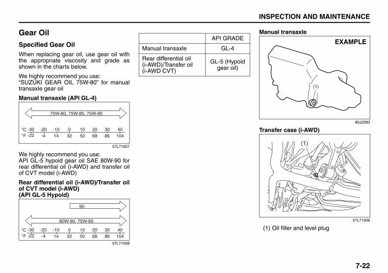
7-22
INSPECTION AND MAINTENANCE
57L20-03E
Gear OilSpecified Gear OilWhen replacing gear oil, use gear oil withthe appropriate viscosity and grade asshown in the charts below.
We highly recommend you use:“SUZUKI GEAR OIL 75W-80” for manualtransaxle gear oil
Manual transaxle (API GL-4)
57L71007
We highly recommend you use:API GL-5 hypoid gear oil SAE 80W-90 forrear differential oil (i-AWD) and transfer oilof CVT model (i-AWD)
Rear differential oil (i-AWD)/Transfer oilof CVT model (i-AWD)(API GL-5 Hypoid)
57L71008
Manual transaxle
80J2083
Transfer case (i-AWD)
57L71006
(1) Oil filler and level plug
CFo
o -30-22
-20-4
-1014 32 50 68 86 104
0 10 20 30 40
75W-80, 75W-85, 75W-90
CFo
o -30-22
-20-4
-1014 32 50 68 86 104
0 10 20 30 40
80W-90, 75W-85
90
API GRADE
Manual transaxle GL-4
Rear differential oil (i-AWD)/Transfer oil (i-AWD CVT)
GL-5 (Hypoid gear oil)
(1)
EXAMPLE
(1)

7-23
INSPECTION AND MAINTENANCE
57L20-03E
Rear differential (i-AWD)
57L71009
(1) Oil filler and level plug
Tightening torque
Gear Oil Level CheckThe manual transaxle, transfer gears (i-AWD CVT) and rear differential (i-AWD)are lubricated with gear oil. To check thegear oil level in any of the above locations,use the following procedure:
1) Park the vehicle on a level surface. Setparking brake and stop the engine.
2) Remove the oil filler plug (1).
For the manual transaxle;3) If gear oil flow from the plug hole, the oil
level is correct. Reinstall the plug.If gear oil do not flow from the plughole, add oil through the filler plug holeuntil a little oil flow from the plug hole.
For the transfer and rear differential;3) Check the inside of the hole with your
finger. If the oil level comes up to thebottom of the plug hole, the oil level iscorrect. If so, reinstall the plug.
4) If the oil level is low, add gear oilthrough the filler plug hole (1) until theoil level reaches the bottom of the fillerhole.
Gear Oil ReplacementSince special procedures, materials andtools are required, it is recommended thatyou trust this job to your authorizedSUZUKI dealer.
Clutch Pedal
57L71010
Check the clutch pedal for smooth opera-tion and clutch fluid level from time to time.If clutch dragging is felt with the pedal fullydepressed, have the clutch inspected byyour SUZUKI dealer. If the clutch fluid levelis near the “MIN” line, fill it up to the “MAX”line with SAE J1703 or DOT3 brake fluid.
Oil Filler Plug
Manual transaxle27 Nm
(19.5 lb-ft) (2.7 kg-m)
Transfer 23 Nm (16.6 lb-ft) (2.3 kg-m)Rear differential
(1)

7-24
INSPECTION AND MAINTENANCE
57L20-03E
Continuously Variable Transaxle (CVT) FluidSpecified FluidUse a CVT fluid SUZUKI CVT FLUIDGREEN-1 or Shell GREEN-1V.
Fluid Level Check
You must check the fluid level with the CVTfluid at normal operating temperature.
To check the fluid level:1) To warm up the CVT fluid, drive the
vehicle or idle the engine until the tem-perature gauge indicates normal oper-ating temperature.
2) Then drive for ten more minutes.
NOTE:Do not check the fluid level if you have justdriven the vehicle for a long time at highspeed, or if you have driven in city traffic in
hot weather. Wait until the fluid cools down(about 30 minutes), or the fluid level indica-tion will not be correct.
3) Park your vehicle on level ground.4) Apply the parking brake and then start
the engine in “P” (Park). Let it idle fortwo minutes and keep it running duringthe fluid level check.
5) With your foot on the brake pedal, movethe gearshift lever through each gear,pausing for about three seconds ineach range. Then move it back to the“P” (Park) position.
75F086
80J2071
80J2072
(1) FULL(2) LOW(3) The lowest point = Fluid level
CAUTIONDriving with too much or too littlefluid can damage the transaxle.
CAUTIONBe sure to use the specified CVTfluid. Using CVT fluid other thanSUZUKI CVT FLUID GREEN-1 or ShellGREEN-1V may damage the CVT ofyour vehicle.
WARNINGBe sure to depress the brake pedalwhen moving the gearshift lever, orthe vehicle can move suddenly.
EXAMPLE
EXAMPLE
(2)
H
C
(1)
(3)
EXAMPLE

7-25
INSPECTION AND MAINTENANCE
57L20-03E
6) The handle of the CVT fluid dipstick iscolored red or orange for easy identifi-cation. Remove the dipstick, clean it and pushit back in until the cap seats. Pull outthe dipstick and read the fluid level. The fluid level should be between thetwo marks in the “HOT” range on thedipstick.
7) Add just enough specified fluid throughthe dipstick hole to fill the transaxle tothe proper level. It takes only 0.6 liters(1.27 US pt) for CVT to raise the levelfrom “LOW” to “FULL”.
Deterioration Checking or Chang-ing FluidSince special procedures, materials andtools are required to check the deteriora-tion of CVT fluid or change, it is recom-mended that you trust this job to yourauthorized SUZUKI dealer.
BrakesBrake Fluid
57L71010
Check the brake fluid level by looking atthe reservoir in the engine compartment.Check that the fluid level is between the“MAX” and “MIN” lines. If the brake fluidlevel is near the “MIN” line, fill it up to the“MAX” line with SAE J1703 or DOT3 brakefluid.
65D477
CAUTIONAfter checking or adding oil, be sureto insert the dipstick securely.
EXAMPLE
WARNINGFailure to follow the guidelines belowcan result in personal injury or seri-ous damage to the brake system.• If the brake fluid in the reservoir
drops below a certain level, thebrake warning light on the instru-ment panel will come on (theengine must be running with theparking brake fully disengaged.)Should the light come on, immedi-ately ask your SUZUKI dealer toinspect the brake system.
• A rapid fluid loss indicates a leak inthe brake system which should beinspected by your SUZUKI dealerimmediately.
• Brake fluid can harm your eyes anddamage painted surfaces. Use cau-tion when refilling the reservoir.
(Continued)

7-26
INSPECTION AND MAINTENANCE
57L20-03E
NOTE:With disc brakes, the fluid level can beexpected to gradually fall as the brakepads wear.
Brake Pedal
65D345
With the engine running and the parkingbrake set, measure the distance betweenthe brake pedal and floor carpet when thepedal is depressed with approximately 300N (66 lbs, 30 kg) of force. The minimumdistance required is as specified. Sinceyour vehicle’s brake system is self-adjust-ing, there is no need for pedal adjustment.If the pedal to floor carpet distance as
measured above is less than the minimumdistance required, have your vehicleinspected by your SUZUKI dealer.
NOTE:When measuring the distance between thebrake pedal and floor wall, be sure not toinclude the floor mat or rubber on the floorwall in your measurement.
60G104
WARNING(Continued)• Do not use any fluid other than SAE
J1703 or DOT3 brake fluid. Do notuse reclaimed fluid or fluid that hasbeen stored in old or open contain-ers. It is essential that foreign parti-cles and other liquids are kept outof the brake fluid reservoir.
WARNINGBrake fluid is harmful or fatal if swal-lowed, and harmful if it comes in con-tact with skin or eyes. If swallowed,do not induce vomiting. Immediatelycontact a poison control center or aphysician. If brake fluid gets in eyes,flush eyes with water and seek medi-cal attention. Wash thoroughly afterhandling. Solution can be poisonousto animals. Keep out of the reach ofchildren and animals.
CAUTIONThe brake fluid should be replacedaccording to the maintenance sched-ule. Have the brake fluid replaced byyour SUZUKI dealer.
Pedal to floor carpet minimum distance“a”
73 mm (2.9 in.)
“a”Floor carpet

7-27
INSPECTION AND MAINTENANCE
57L20-03E
Parking Brake Lever
60A226
Check the parking brake for proper adjust-ment by counting the number of clicksmade by the ratchet teeth as you slowlypull up on the parking brake lever to thepoint of full engagement. The parkingbrake lever should stop between the speci-fied ratchet teeth and the rear wheelsshould be securely locked. If the parkingbrake is not properly adjusted or thebrakes drag after the lever has been fullyreleased, have the parking brake inspectedand/or adjusted by your SUZUKI dealer.
Steering Wheel
80J005
Check the play of the steering wheel bygently turning it from left to right and mea-suring the distance that it moves beforeyou feel slight resistance. The play shouldbe between the specified values. Checkthat the steering wheel turns easily andsmoothly without rattling by turning it all theway to the right and to the left while drivingvery slowly in an open area. If the amountof free play is outside the specification oryou find anything else to be wrong, aninspection must be performed by yourSUZUKI dealer.
WARNINGIf you experience any of the followingproblems with your vehicle’s brakesystem, have the vehicle inspectedimmediately by your SUZUKI dealer.• Poor braking performance• Uneven braking (brakes not work-
ing uniformly on all wheels.)• Excessive pedal travel• Brake dragging• Excessive noise• (Except ABS equipped vehicle)
Pedal pulsation (pedal pulsateswhen pressed for braking.)
Ratchet tooth specification “b”
6th – 8th
200 N (44 lbs, 20 kg)
“b”
Steering wheel play “c”
0 – 30 mm (0.0 – 1.2 in.)
“c”
EXAMPLE

7-28
INSPECTION AND MAINTENANCE
57L20-03E
TiresFor safe operation of your vehicle, it isimportant that the tires be the correcttype and size, in good condition, andproperly inflated. Be sure to follow therequirements and recommendations inthis section.
Tire Sidewall LabelingUseful information about a tire ismolded into its sidewall. The examplebelow shows a typical passenger cartire.
Typical Passenger Car Tire Sidewall
67D027
A. Tire Manufacturer The name of the tire manufactureris shown here.
B. Tire Name/Model The tire name or model is shownhere.
C. Tire Size The tire size code is a combina-tion of letters and numbers usedto define a particular tire’s width,height, aspect ratio, constructiontype, and service description. Seethe “Tire Size” explanation later inthis section for more details.
D. U.S. DOT Tire Identification Num-ber The Department of Transportation(DOT) marking indicates that thetire is in compliance with the U.S.Department of TransportationMotor Vehicle Safety Standards.The letters and numbers followingthe DOT marking is the Tire Iden-tification Number (TIN). The TINidentifies the tire manufacturerand plant, tire size, and date thetire was manufactured.
E. Uniform Tire Quality Grading(UTQG) Tire manufacturers are required tograde tires based on three perfor-mance factors: treadwear, tractionand temperature resistance.Refer to the “Uniform Tire QualityGrading” section for more details.
F. Load Rating Load rating is the maximumweight a tire is designed to sup-port in normal service.
G. Max Inflation Pressure Max inflation pressure is the max-imum inflation pressure a tire isdesigned for.
H. Tire Ply Material These tire markings describe thetype of cord and number of pliesin the sidewall and under thetread.
I. Load Index and Speed Rating The two- or three-digit number isthe tire’s load index, the maximumload a tire can carry at the speedindicated by its speed symbol atthe maximum inflation pressure.The higher the number is, thegreater the load carrying capacity.The letter symbol denotes thespeed at which a tire is designedto be driven for extended periodsof time. (Ratings are listed below.)A
HB
G
EF
D
J
IC
Letter Rating Speed Rating
Q 99 mph
R 106 mph
S 112 mph
T 118 mph

7-29
INSPECTION AND MAINTENANCE
57L20-03E
*The letters ZR may be used on tireswith a maximum speed capability over149 mph and will always be used ontires with a maximum speed capabilityover 186 mph.
J. M+S Marking This marking indicates the tirehas some mud and snow capabili-ties and is designed for all-seasonuse.
Tire SizeThe following illustration shows anexample of a typical passenger car tiresize.
67D028
A. Tire Type This letter code indicates the pri-mary intended use of the tire. Theletter “P” identifies a tire primarilyintended for use on a passengervehicle.
B. Tire Width This three-digit number indicatesthe tire section width in millime-ters from sidewall to sidewall.
C. Aspect Ratio This two-digit number representsthe tire section height divided bythe tire section width.
D. Construction Code This letter code is used to indicatethe type of ply construction in thetire. The letter “R” means radialply tire construction, the letter “D”means diagonal or bias ply con-struction, and the letter “B” meansbelted-bias ply construction.
E. Rim Diameter This two-digit number is the wheelor rim diameter in inches.
U 124 mph
H 130 mph
V 149 mph
W 168 mph*
Y 186 mph*
A B C D EWARNING
Your SUZUKI is equipped withtires which are all the same typeand size. This is important toensure proper steering and han-dling of the vehicle. Never mixtires of different size or type onthe four wheels of your vehicle.Mixing tires could cause you tolose control while driving whichmay lead to an accident. The sizeand type of tires used should beonly those approved by SUZUKIMotor Corporation as standard oroptional equipment for your vehi-cle.

7-30
INSPECTION AND MAINTENANCE
57L20-03E
Tire Inflation PressureTire inflation pressure should bechecked when the tire is cold. “Coldtire inflation pressure” is the pressurein a tire that has been driven less than1 mile (1.6 km) or has been standingfor three hours or more.
80JS025
The front and rear tire pressure speci-fications for your vehicle are shownbelow and are listed on the Tire andLoading Information Label, which islocated on the driver’s door lock pillar.The Tire and Loading InformationLabel contains the following informa-tion:
• Seating Capacity• Maximum Allowed Combined
Weight of Occupants and Cargo• Original Tire Size• Recommended Cold Tire Inflation
Pressure of Original Tires• Size of Compact Spare Tire• Recommended Cold Tire Inflation
Pressure of Compact Spare Tire
NOTE:The tire inflation pressure will changedue to changes in atmospheric pres-sure, temperature or tire temperaturewhen driving. To reduce the chancethat the low tire pressure warning lightwill come on due to normal changes intemperature and atmospheric pres-sure, it is important to check andadjust the tire pressures when the tiresare cold. Tires that appear to be at thespecified pressure when checked afterdriving, when the tires are warm, couldhave pressure below the specificationwhen the tires cool down. Also, tiresthat are inflated to the specified pres-sure in a warm garage may have pres-sure below the specification when thevehicle is driven outside in very coldtemperature. If you adjust the tirepressure in a garage that is warmerthan the outside temperature, youshould add 1 psi to the recommendedcold tire inflation pressure for every10°F difference between garage tem-perature and outside temperature.
EXAMPLE
Recommended Cold Tire InflationPressures
Front Tires 260 kPa38 psi
Rear Tires 260 kPa38 psi
Compact Spare Tire 420 kPa60 psi

7-31
INSPECTION AND MAINTENANCE
57L20-03E
Measuring Air PressureUse the following steps to achieveproper tire inflation:1) Identify the recommended tire pres-
sure on the vehicle’s Tire and Load-ing Information Label or in theowner’s manual.
2) Remove the valve cap from the tirevalve stem.
3) Using a reliable pressure gauge,measure the tire inflation pressureby pressing the tire gauge firmlyonto the valve to get a pressuremeasurement. Remember thatinflation pressures should bechecked when the tires are “cold”,meaning before they have beendriven one mile or after sitting forthree hours or more allowing thetire to cool to ambient air tempera-ture.
4) If the air pressure is too high, slowlyrelease the air by pressing on thetire valve stem with the edge of thetire gauge until you reach the cor-rect pressure.
5) If the air pressure is too low, fill thetire with air at a service station untilit reaches the recommended pres-sure.
6) Make sure all tires have the sameair pressure (unless the owner’smanual indicates otherwise).
Tire InspectionInspect your vehicle’s tires at leastonce a month by performing the fol-lowing checks: 1) Measure the air pressure with a tire
gauge. Adjust the pressure if nec-essary. Remember to check thespare tire, too. Refer to the “Mea-suring Air Pressure” section.
54G136
(1) Tread wear indicator(2) Indicator location mark
2) Check that the depth of the treadgroove is more than 1.6 mm (0.06in.). To help you check this, the tireshave molded-in tread wear indica-tors in the grooves. When the indi-cators appear on the tread surface,the remaining depth of the tread is
WARNING
• Air pressures should bechecked when the tires are coldor you may get inaccurate read-ings.
• Check the inflation pressurefrom time to time while inflatingthe tire gradually, until the spec-ified pressure is obtained.
• Never underinflate or overin-flate the tires. Underinflation can causeunusual handling characteristicsor can cause the rim to slip onthe tire bead, resulting in an acci-dent or damage to the tire or rim. Underinflation can also causetires to overheat, leading to tirefailure. Overinflation can cause the tireto burst, resulting in personalinjury. Overinflation can also causeunusual handling characteristicswhich may result in an accident.

7-32
INSPECTION AND MAINTENANCE
57L20-03E
1.6 mm (0.06 in.) or less and thetire should be replaced.
3) Check for abnormal wear, cracksand damage. Any tires with cracksor other damage should bereplaced. If any tires show abnor-mal wear, have them inspected byyour SUZUKI dealer.
4) Check for loose wheel nuts.5) Check that there are no nails,
stones or other objects sticking intothe tires.
WARNING
Hitting curbs and running overrocks can damage tires and affectwheel alignment. Be sure to havetires and wheel alignmentchecked periodically by yourSUZUKI dealer.
WARNING
Your SUZUKI is equipped withtires which are all the same typeand size. This is important toensure proper steering and han-dling of the vehicle. Never mixtires of different size or type onthe four wheels of your vehicle.The size and type of tires usedshould be only those approved bySUZUKI Motor Corporation asstandard or optional equipmentfor your vehicle.
CAUTION
For intelligent All Wheel Drive (i-AWD) models, replacing a tirewith one of a different size, orusing different brands among thefour tires can result in damage tothe drive train.
WARNING
Replacing the wheels and tiresequipped on your vehicle withcertain combinations of aftermar-ket wheels and tires can signifi-cantly change the steering andhandling characteristics of yourvehicle. Oversized tires may alsorub against the fender overbumps, causing vehicle damageor tire failure. Therefore, use onlythose wheel and tire combina-tions approved by SUZUKI MotorCorporation as standard oroptional equipment for your vehi-cle. For information regarding thespecified tires, refer to the TireInformation Label located on thedriver’s side door pillar or the“SPECIFICATIONS” section.
CAUTION
Replacing the original tires withtires of a different size may resultin false speedometer or odometerreadings. Check with yourSUZUKI dealer before purchas-ing replacement tires that differ insize from the original tires.
7-33
INSPECTION AND MAINTENANCE
57L20-03E
Uniform Tire Quality GradingThe U.S. National Highway TrafficSafety Administration has developed agrading system for evaluating the per-formance of passenger car tires. Thefollowing information will help youunderstand the grading system, whichapplies to vehicles sold in the U.S.Consult your SUZUKI dealer or tireretailer for help in choosing the correctreplacement tires for your vehicle.
Quality grades can be found whereapplicable on the tire sidewall betweentread shoulder and maximum sectionwidth. For example:
Treadwear 200 Traction AA Tempera-ture A
DOT Quality GradesTreadwearTraction AA A B CTemperature A B CAll Passenger Car Tires Must ConformTo Federal Safety Requirements inAddition To These Grades
TreadwearThe treadwear grade is a comparativerating based on the wear rate of the tirewhen tested under controlled condi-tions on a specified government testcourse. For example, a tire graded 150would wear one and one-half (1 1/2)times as well on the government courseas a tire graded 100. The relative per-formance of tires depends upon theactual conditions of their use, howeverand may depart significantly from thenorm due to variations in driving habits,service practices and differences inroad characteristics and climate.
Traction – AA, A, B, CThe traction grades, from highest tolowest, are AA, A, B and C. Thosegrades represent the tire’s ability tostop on wet pavement as measuredunder controlled conditions on speci-fied government test surfaces ofasphalt and concrete. A tire marked Cmay have poor traction performance.
Temperature – A, B, CThe temperature grades are A (thehighest), B and C, representing thetire’s resistance to the generation ofheat and its ability to dissipate heatwhen tested under controlled condi-tions on a specified indoor laboratorytest wheel. Sustained high tempera-ture can cause the material of the tireto degenerate and reduce tire life, andexcessive temperature can lead tosudden tire failure. The grade C corre-sponds to a level of performancewhich all passenger car tires mustmeet under the Federal Motor VehicleSafety Standard No. 109. Grades Band A represent higher levels of per-formance on the laboratory test wheelthan the minimum required by law.
WARNING
The traction grade assigned tothis tire is based on straight-ahead braking traction tests, anddoes not include acceleration,cornering, hydroplaning or peaktraction characteristics.
WARNING
The temperature grade for thistire is established for a tire that isproperly inflated and not over-loaded. Excessive speed, under-inflation or excessive loading,either separately or in combina-tion, can cause heat buildup andpossible tire failure.

7-34
INSPECTION AND MAINTENANCE
57L20-03E
Tire Rotation
54G114
To avoid uneven wear of your tires andto prolong their life, rotate the tires asillustrated. Tires should be rotated asrecommended in the periodic mainte-nance schedule. After rotation, adjustfront and rear tire pressures to thespecification listed on your vehicle’sTire and Loading Information Label.
Compact Spare Tire (if equipped)
54G115
(1) Wear indicator(2) Indicator location mark
Your vehicle comes equipped with thecompact spare tire. The compactspare is designed to save space inyour storage area, and its lighterweight makes it easier to install if a flattire occurs. It is only intended for tem-porary emergency use, until the con-ventional tire can be repaired orreplaced. The inflation pressure of thecompact spare tire should be checkedat least monthly. Use a quality pocket-type inflation pressure gauge and setat 420 kPa (60 psi). At the same time,check that the tire is stored securely. Ifit is not, tighten it.
WARNING
Rust or dirt on a wheel, or on theparts to which it is fastened, canmake wheel nuts become looseafter a time. The wheel couldcome off and cause an accident.When you change a wheel,remove any rust or dirt fromplaces where the wheel attachesto the vehicle. In an emergency,you can use a cloth or a papertowel to do this; but be sure touse a scraper or wire brush later,if you need to, to get all the rustor dirt off.

7-35
INSPECTION AND MAINTENANCE
57L20-03E
Note that two or more compact sparetires should not be used on one vehi-cle simultaneously.
Snow TiresYour vehicle is equipped with all-sea-son tires which are designed for use insummer and most winter conditions.For improved traction in severe winterconditions, SUZUKI recommendsmounting radial snow tires on all fourwheels. Snow tires must be the samesize as the standard tires. Also be sureto use the tires of the same type andbrand on all four wheels of your vehi-cle.
WARNING
The compact spare tire and wheelare intended for temporary emer-gency use only. Continuous useof this spare can result in tire fail-ure and loss of control. Alwaysobserve these precautions whenusing this spare:• Your vehicle will handle differ-
ently with this temporary spare.• Do not exceed 80 km/h (50 mph)
speed.• Replace this spare with a stan-
dard tire and wheel as soon aspossible.
• Use of this spare will reduceground clearance.
• Recommended air pressure forthis spare is 420 kPa (60 psi).
• Do not use tire chains on thecompact spare. If you must usetire chains, rearrange thewheels so standard tires andwheels are fitted to the frontaxle.
(Continued)
WARNING
(Continued)• The compact spare tire has a
much shorter tread life than theconventional tires on your vehi-cle. Replace the tire as soon asthe tread wear indicatorappears.
• When replacing the compacttire, use a replacement tire withthe exact same size and con-struction.
CAUTION
For intelligent All Wheel Drive (i-AWD) models, driving with anunderinflated compact spare tireor over 80 km/h (50 mph) whileusing a compact spare tire canresult in damage to the drivetrain.

7-36
INSPECTION AND MAINTENANCE
57L20-03E
GLOSSARY OF TIRE TERMINOL-OGYAccessory Weight – the combinedweight (in excess of those standarditems which may be replaced) of CVT,power steering, power brakes, powerwindows, power seats, radio, andheater, to the extent that these itemsare available as factory-installedequipment (whether installed or not).
Cold Tire Inflation Pressure – the pres-sure in a tire that has been driven lessthan 1 mile or has been standing forthree hours or more.
Curb Weight – the weight of a motorvehicle with standard equipmentincluding the maximum capacity offuel, oil, and coolant, and, if soequipped, air conditioning and addi-tional weight optional engine.
Intended Outboard Sidewall – (1) thesidewall that contains a whitewall,bears white lettering or bears manu-facturer, brand, and/or model namemolding that is higher or deeper thanthe same molding on the other side-wall of the tire, or (2) the outward fac-ing sidewall of an asymmetrical tirethat has a particular side that mustalways face outward when mountedon a vehicle.
Maximum Inflation Pressure – the max-imum cold inflation pressure a tire isdesigned to support in normal service.
Maximum Loaded Vehicle Weight –the sum of curb weight, accessoryweight, vehicle capacity weight (totalload capacity), and production optionsweight.
Normal Occupant Weight – 68 kilo-grams times the number of occupantsspecified in the second column ofTable 1 (shown below).
Occupant distribution – distribution ofoccupants in a vehicle as specified inthe third column of Table 1 (shownbelow).
Production Options Weight – the com-bined weight of those installed regularproduction options weighing over 2.3kilograms in excess of those standarditems which they replace, not previ-ously considered in curb weight oraccessory weight, including heavyduty brakes, ride levelers, roof rack,heavy duty battery, and special trim.
Recommended Inflation Pressure –the cold tire inflation pressure recom-mended by a manufacturer.
Rim – metal support for a tire or tireand tube assembly upon which the tirebeads are seated.
Vehicle Capacity Weight – the ratedcargo and luggage load plus 68 kilo-grams (150 lbs) times the vehicle’sdesignated seating capacity.
Vehicle Maximum Load on the Tire –the load on an individual tire that isdetermined by distributing to each axleits share of the maximum loaded vehi-cle weight and dividing by two.
Vehicle Normal Load on the Tire – theload on an individual tire that is deter-mined by distributing to each axle itsshare of the curb weight, accessoryweight, and normal occupant weight(distributed in accordance with Table 1shown below) and dividing by 2.
TABLE 1 – Occupant Loading andDistribution For Vehicle NormalLoad For Various Designated Seat-ing Capacities
Designated seating capacity, number of occupants
Vehicle nor-mal load, number of occupants
Occupant distribution in a nor-mally loaded vehicle
2 through 4 2 2 in front
5 through 10 32 in front,
1 in second seat

7-37
INSPECTION AND MAINTENANCE
57L20-03E
Vehicle LoadingYour vehicle was designed for specificload capacities. The load capacities ofyour vehicle are indicated by theGross Vehicle Weight Rating (GVWR),the Gross Axle Weight Rating (GAWR,front and rear), and the total loadcapacity, the seating capacity, and thecargo load capacity. The GVWR andGAWR (front and rear) are listed onthe Safety Certification Label which islocated below the driver’s side doorlatch striker. The total load capacityand seating capacity are listed on theTire and Loading Information Labelwhich is located below the Safety Cer-tification Label. The cargo load capac-ity can be determined as describedbelow.
Cargo Load Capacity – Maximumweight of cargo and luggage that thevehicle can safely carry. Cargo loadcapacity is the difference between thetotal load capacity of the vehicle andthe total combined weight of all vehicleoccupants. Refer to “Steps for Deter-mining Correct Load Limit” for detailson how to determine cargo loadcapacity.
GVWR – Maximum permissible overallweight of the fully loaded vehicle(including all the occupants, accesso-ries and cargo plus the trailer tongueweight if towing a trailer).
GAWR – (Front and Rear) Maximumpermissible weight on an individualaxle.
Seating Capacity – Maximum numberof occupants the vehicle is designed tocarry.
NOTE:Even though the number of occupantsis within the seating capacity, you stillmust make sure that you do notexceed the total load capacity of thevehicle.
Total Load Capacity – Maximum per-missible weight a vehicle can carryincluding the weight of all the occu-pants, accessories, cargo, plus trailertongue weight (if towing a trailer).
The weight of any accessories alreadyinstalled on your vehicle at the time ofpurchase, or that you or the dealerinstall after purchase, must be sub-tracted from the total load capacity todetermine how much capacity remainsavailable for occupants, cargo, andtrailer tongue weight (if towing a
trailer). Contact your dealer for furtherinformation.
Actual weight of the loaded vehicleand actual loads at the front and rearaxles can only be determined byweighing the vehicle using a vehiclescale. To measure the weight andload, try making your vehicle to a high-way weighing station, shipping com-pany or inspection station for trucks,etc. Compare these weights to theGVWR and GAWR (front and rear)listed on the Safety Certification Label.If the gross vehicle weight or the loadon either axle exceeds these ratings,you must remove enough weight tobring the load down to the ratedcapacity.

7-38
INSPECTION AND MAINTENANCE
57L20-03E
Steps for Determining Correct LoadLimit1) Locate the statement “The com-
bined weight of occupants andcargo should never exceed XXX kgor XXX lbs” on your vehicle’s plac-ard.
2) Determine the combined weight ofthe driver and passengers that willbe riding in your vehicle.
3) Subtract the combined weight ofthe driver and passengers fromXXX kg or XXX lbs.
4) The resulting figure equals theavailable amount of cargo and lug-gage load capacity. For example, ifthe “XXX” amount equals 1400 lbsand there will be five 150 lb passen-gers in your vehicle, the amount ofavailable cargo and luggage loadcapacity is 650 lbs (1400 – 750 (5 x150) = 650 lbs).
5) Determine the combined weight ofluggage and cargo being loaded onthe vehicle. That weight may notsafely exceed the available cargoand luggage load capacity calcu-lated in Step 4.
6) If your vehicle will be towing atrailer, load from your trailer will betransferred to your vehicle. Consultthis manual to determine how thisreduces the available cargo and lug-gage load capacity of your vehicle.
Vehicle Loading ExampleAs an example, suppose that the Tireand Loading Information label on yourvehicle indicates that your vehicle’stotal load capacity is 950 lbs. If youwere to drive your vehicle with onepassenger, and the total combinedweight of you and your passenger was350 lbs, then the cargo and luggagecapacity of your vehicle would be 600lbs (950 – 350 = 600 lbs).If you later added 2 more passengers,having a combined weight of 325 lbs,the cargo and luggage capacity ofyour vehicle would be reduced from600 lbs to 275 lbs (600 – 325 = 275lbs). As you can see, as the numberand combined weight of vehicle occu-pants increase, the vehicle’s cargoand luggage capacity decreases.Suppose again, that you were to takea trip in your vehicle with the samethree passengers described above,and you decided to tow a trailer havinga trailer tongue weight of 75 lbs. Thecargo and luggage capacity would bereduced again, to 200 lbs (275 – 75 =200 lbs).
WARNING
Never overload your vehicle. Over-loading your vehicle can causedamage to your tires and lead topoor steering and braking whichcan result in an accident. Thegross vehicle weight (sum of theweights of the loaded vehicle,driver and passengers) mustnever exceed the Gross VehicleWeight Rating (GVWR) listed onthe Safety Certification Label. Inaddition, never distribute a load sothat the weight on either the frontor rear axle exceeds the GrossAxle Weight Rating (GAWR) listedon the Safety Certification Label.
WARNING
• Always distribute cargo evenly.• To avoid personal injury or
damage to your vehicle, alwayssecure cargo to prevent it fromshifting if the vehicle movessuddenly.
• Place heavier objects on thefloor and as far forward in thecargo area as possible. Neverpile cargo higher than the top ofthe seatbacks.

7-39
INSPECTION AND MAINTENANCE
57L20-03E
Determining Compatibility of Tireand Vehicle Load LimitsThe tires on your vehicle, when theyare inflated to the recommended tireinflation pressure, have a load-carry-ing capacity that is greater than theload that will be on the tires when thevehicle is at its GVWR or GAWR limit.Never use replacement tires that havea load-carrying capacity less than theoriginal tires on your vehicle. Tire load-carrying capacity information ismolded into the tire sidewall typicallyshown as “Max. Load”. Use of replace-ment tires with a lower load-carryingcapacity than the original tires, or fail-ure to keep the tires inflated to recom-mended tire pressure, may reduce theGVWR or GAWR limit of your vehicle.
NOTE:Use of replacement tires with a higherload-carrying capacity than the origi-nal tires, or using a tire inflation pres-sure higher than the recommendedtire inflation pressure, will not increasethe GVWR or GAWR limit of your vehi-cle.
Battery
60A269
Your vehicle is equipped with a battery thatrequires infrequent maintenance. You willnever have to add water. You should, how-ever, periodically check the battery, batteryterminals and battery hold-down bracketfor corrosion. Remove corrosion using astiff brush and ammonia mixed with water,or baking soda mixed with water. Afterremoving corrosion, rinse with clean water.
The test indicator on the top of the batteryprovides information on the condition ofthe battery.
If your vehicle is not going to be driven fora month or longer, disconnect the cablefrom the negative terminal of the battery tohelp prevent discharge.
WARNINGBatteries produce flammable hydro-gen gas. Keep flames and sparksaway from the battery or an explosionmay occur. Never smoke when work-ing near the battery.
WARNINGWhen checking or servicing the bat-tery, disconnect the negative cable.Be careful not to cause a short circuitby allowing metal objects to contactthe battery posts and the vehicle atthe same time.
EXAMPLE
WARNINGTo avoid harm to yourself or damageto your vehicle or battery, follow thejump starting instructions in the“EMERGENCY SERVICE” section ofthis manual if it is necessary to jumpstart your vehicle.
WARNINGBattery posts, terminals and relatedaccessories contain lead and leadcompounds. Wash hands after han-dling.

7-40
INSPECTION AND MAINTENANCE
57L20-03E
FusesYour vehicle has three types of fuses, asdescribed below:
Main Fuse – The main fuse takes currentdirectly from the battery.
Primary Fuses – These fuses are betweenthe main fuse and individual fuses, and arefor electrical load groups.
Individual Fuses – These fuses are for indi-vidual electrical circuits.
For details on protected circuits, refer tothe “Fuses and Protected Circuits” sectionin this manual.
To remove a fuse, use the fuse puller pro-vided in the fuse box.
57L71011
Fuses in the Engine Compartment
57L71037
1
10
11
12
13
14
15
16
17
19
20
21
22
23
24
25
26
29
30
31
32
33
3427
28
37
38
39
4041
4443 42
45
35
36
18
2
3
4
5
6
7
8
9
USE THE DESIGNATED FUSES AND RELAYS ONLY
NO. AMPS FUSE NAME
(1) 50A Ignition switch
(2) 30A Radiator fan sub
(3) 30A Radiator fan main
(4) 30A Starting motor
(5) 40A Light
(6) 40A ESP control module
(7) 50A Keyless start controlmodule
(8) 50A Power window, Powerseat
(9) 50A Blower fan
(10) 10A Air conditioning com-pressor
(11) 15A Door mirror heater
(12) 15A Throttle motor
(13) 30A Rear defogger
(14) 30A Blank
(15) 7.5A Head light
(16) 20A Fuel injection
(17) 25A ESP control module
(18) 25A Back up
(19) 15A Head light low (Left)

7-41
INSPECTION AND MAINTENANCE
57L20-03E
The main fuse, primary fuses and some ofthe individual fuses are located in theengine compartment. If the main fuseblows, no electrical component will func-tion. If a primary fuse blows, no electricalcomponent in the corresponding loadgroup will function. When replacing themain fuse, a primary fuse or an individualfuse, use a genuine SUZUKI replacement. To remove a fuse, use the fuse puller pro-vided in the fuse box. The amperage ofeach fuse is shown in the back of the fusebox cover.
60A243
NOTE:Make sure that the fuse box always carriesspare fuses.
(20) 15A Head light low (Right)
(21) 15A Head light high (Left)
(22) 15A Head light high (Right)
(23) 15A CVT
(24) 20A Front fog light
(25) 15A O2 sensor heater
(26) 15A Horn
(27) – Head light low relay(Left)
(28) – Head light low relay(Right)
(29) – Blank
(30) – Blank
(31) – Blank
(32) – Air conditioning com-pressor relay
(33) – Rear defogger relay
(34) – Blank
(35) – Windshield wiper relay2
(36) – Blank
(37) – Windshield wiper relay1
(38) – Starting motor relay
(39) – Fuel pump relay
(40) – Radiator fan relay 3
(41) – Radiator fan relay 1
(42) – Door mirror heaterrelay
(43) – Radiator fan relay 2
(44) – Main relay
(45) – Throttle motor relay
WARNINGIf the main fuse or a primary fuseblows, be sure to have your vehicleinspected by an authorized SUZUKIdealer. Always use a genuine SUZUKIreplacement. Never use a substitutesuch as a wire even for a temporaryfix, or extensive electrical damageand a fire can result.
BLOWN
OK

7-42
INSPECTION AND MAINTENANCE
57L20-03E
Fuses under the Dash BoardDriver’s side
57L71012
(1) Driver’s side fuse box
57L70027
(2) Dashboard undercover(3) Clips
57L70034
The fuses are also located under thedriver’s side of the dashboard. To accessthese fuses, pull the dashboard under-cover to release its clip engagements andthen remove the undercover. The amper-age of each fuse is shown on the top of thedashboard undercover.
(1)
EXAMPLE
(2)
(3)
(3)
NO. AMPS FUSE NAME
(1) 30A Power window
(2) 15A Windshield washermotor
(3) 20A Seat heater
(4) 25A Windshield wiper motor
(5) 7.5A IG2 SIG
(6) 15A Ignition coil
(7) 15A Accessory 2
(8) 15A Accessory
(9) 10A ESP control module
(10) 7.5A Cruise control
1
2
1211
4 5 6 7 8
15 16
26
17
2524
1413
232221201918
109
3
(11) 7.5A IG1 SIG
(12) 7.5A Blank
(13) 7.5A Meter
(14) 10A Back-up light
(15) 10A Air bag
(16) 15A Steering lock
(17) 7.5A BCM
(18) 20A Sunroof
(19) 7.5A Blank
(20) 10A Tail light
(21) 10A Brake light
(22) 10A Hazard
(23) 20A Front power window(Left)
(24) 15A Radio
(25) 10A Dome light
(26) 20A Door lock

7-43
INSPECTION AND MAINTENANCE
57L20-03E
Passenger’s side
57L71013
(1) Passenger’s side fuse box
57L70030
(2) Dashboard undercover(3) Screw
57L70016
CAUTIONRemove the dashboard undercoverwhile being careful not to damage thewiring fitted on it. If the wiring is dam-aged, the courtesy lights will notwork.
(1)
EXAMPLE
(2)
(3)
NO. AMPS FUSE NAME
(1) 20A Rear power window (Right)
(2) 20A Rear power window (Left)
(3) 20A Front power window (Right)
(4) 15A 4WD
(5) 20A Battery fan
(6) 20A Audio
(7) 30A Power seat (Right)
(8) 30A Power seat (Left)
(9) 30A Blank
1
6 7 8 9
2 3 4 5

7-44
INSPECTION AND MAINTENANCE
57L20-03E
The fuses are also located under the pas-senger’s side of the dashboard. Removethe two screws and dashboard undercover. The amperage of each fuse isshown on the top of the dashboard undercover.
81A283
Headlight AimingSince special procedures are required, werecommend you take your vehicle to yourSUZUKI dealer for headlight alignment.
CAUTIONRemove the dashboard undercoverwhile being careful not to damage thewiring fitted on it. If the wiring is dam-aged, the courtesy lights will notwork.
BLOWNOK
WARNINGAlways be sure to replace a blownfuse with a fuse of the correct amper-age. Never use a substitute such asaluminum foil or wire to replace ablown fuse. If you replace a fuse andthe new one blows in a short periodof time, you may have a major electri-cal problem. Have your vehicleinspected immediately by yourSUZUKI dealer.

7-45
INSPECTION AND MAINTENANCE
57L20-03E
Bulb Replacement
NOTE:If it is difficult to replace headlight bulbs orposition light bulbs due to under-hoodcomponents trust this job to your dealer.
Interior LightFront dome light
57L71014
Pull down the lens by using a flat bladescrewdriver covered with a soft cloth asshown. To install it, simply push it back in.
Rear dome Light
57L71015
Pull down the lens by using a flat bladescrewdriver covered with a soft cloth asshown. To install it, simply push it back in.
The bulb can be removed by simply pullingit out. When replacing the bulb, make surethat the contact springs are holding thebulb securely.
WARNING• Light bulbs can be hot enough to
burn your finger right after beingturned off. This is true especiallyfor halogen headlight bulbs.Replace the bulbs after theybecome cool enough.
• The headlight bulbs are filled withpressurized halogen gas. They canburst and injure you if they are hitor dropped. Handle them carefully.
CAUTIONThe oils from your skin may cause ahalogen bulb to overheat and burstwhen the lights are on. Grasp a newbulb with a clean cloth.
CAUTIONFrequent replacement of a bulb indi-cates the need for an inspection ofthe electrical system. This should becarried out by your SUZUKI dealer.
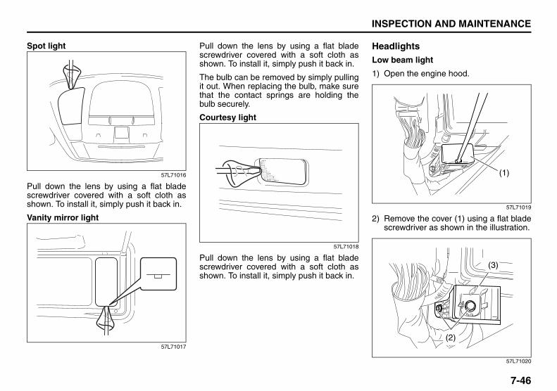
7-46
INSPECTION AND MAINTENANCE
57L20-03E
Spot light
57L71016
Pull down the lens by using a flat bladescrewdriver covered with a soft cloth asshown. To install it, simply push it back in.
Vanity mirror light
57L71017
Pull down the lens by using a flat bladescrewdriver covered with a soft cloth asshown. To install it, simply push it back in.
The bulb can be removed by simply pullingit out. When replacing the bulb, make surethat the contact springs are holding thebulb securely.
Courtesy light
57L71018
Pull down the lens by using a flat bladescrewdriver covered with a soft cloth asshown. To install it, simply push it back in.
HeadlightsLow beam light
1) Open the engine hood.
57L71019
2) Remove the cover (1) using a flat bladescrewdriver as shown in the illustration.
57L71020
(1)
(3)
(2)

7-47
INSPECTION AND MAINTENANCE
57L20-03E
3) Remove the bolts (2) to remove thebracket (3).
57L71021
4) Turn the cover (4) counterclockwise toremove it.
57L71022
5) Disconnect the coupler (5).
57L71023
6) Push the retainer (6) in the direction ofthe arrow (see the illustration) to detachit from the hook (7).
7) Replace the bulb, then follow the abovesteps in reverse to restore the originalstate.
High beam light
1) Open the engine hood.
57L70036
2) To create the space necessary for per-forming the steps that follow, discon-nect the coupler (1) by pressing theclaw.
(4)
(5)
(7)
(6)
(2)
(1)

7-48
INSPECTION AND MAINTENANCE
57L20-03E
3) Turn the cover (2) counterclockwise toremove it.
57L70037
4) Disconnect the coupler (3).
57L70038
5) Push the retainer (4) in the direction ofthe arrow (see the illustration) to detachit from the hook (5).
6) Replace the bulb, then follow the abovesteps in reverse to restore the originalstate.
Other General LightsBulb holder
54G123
(1) Removal(2) Installation
To remove a bulb holder from a light hous-ing, turn the holder counterclockwise andpull it out. To install the holder, push theholder in and turn it clockwise.
(3)
(4)
(5)
(1)
(1)
(2)
(2)
EXAMPLE

7-49
INSPECTION AND MAINTENANCE
57L20-03E
Bulb
54G124
(3) Removal(4) Installation
There are two types of bulb, “Full glasstype” (1) and “Glass/metal type” (2).
To remove and install a full glass type bulb(1), simply pull out or push in the bulb.
To remove a glass metal type bulb (2) froma bulb holder, push in the bulb and turn itcounterclockwise. To install a new bulb,push it in and turn it clockwise.
You can access the individual bulb or bulbholders as follows.
Front parking lights
1) Open the engine hood.
57L70036
2) To create the space necessary for per-forming the steps that follow, discon-nect the coupler (1) by pressing theclaw.
3) Turn the cover (2) counterclockwise toremove it.
57L70037
4) Disconnect the coupler (3).
57L71027
(1)
(2)
(3)
(4)
EXAMPLE
(2)
(1)
(3)
(4)
(3)

7-50
INSPECTION AND MAINTENANCE
57L20-03E
5) Pull on the cable (4) toward the rear ofthe vehicle to remove the bulb socket(5) from the parking light body.
NOTE:You can remove the parking light’s bulbsocket only by pulling on the cable, but thismethod must never be used to remove thebulb sockets of any other lights.
6) Replace the bulb, then follow the abovesteps in reverse to restore the originalstate.
Side turn signal lights
57L71028
1) Pull out the rear end of the side turnsignal light (1) while pushing it towardthe front of the vehicle as shown in theillustration.
57L71029
2) Disconnect the coupler while pushingthe lock release (2) on it.
3) Replace the side turn signal light (1),then follow the above steps in reverseto restore the original state.
Front fog light (if equipped)
1) Start the engine. To facilitate bulbreplacement, turn the steering wheelaway from the front fog light whose bulbis to be replaced, then turn off theengine.
57L70039
2) Remove the screw (1).
(1)
(2)
(1)
EXAMPLE

7-51
INSPECTION AND MAINTENANCE
57L20-03E
57L70040
3) Remove the screws (2).
57L70041
4) Remove the part of the bumper (3) indi-cated in the illustration.
80JM071
5) Disconnect the coupler with pushingthe lock release. Turn the bulb holdercounterclockwise and remove it.
6) Replace the bulb, then follow the abovesteps in reverse to restore the originalstate.
Side marker lights
1) Start the engine. To facilitate bulbreplacement, turn the steering wheelaway from the side marker light whosebulb is to be replaced, then turn off theengine.
57L70039
2) Remove the screw (1).
57L70040
3) Remove the screws (2).
(2) (2)(2)
EXAMPLE
(3)
EXAMPLE
(1)
EXAMPLE
(2) (2)(2)
EXAMPLE

7-52
INSPECTION AND MAINTENANCE
57L20-03E
57L70041
4) Remove the part of the bumper (3) indi-cated in the illustration.
57L71030
5) Disconnect the coupler with pushingthe lock release. Turn the bulb holdercounterclockwise and remove it.
6) Replace the bulb, then follow the abovesteps in reverse to restore the originalstate.
Front turn signal lights
1) Start the engine. To facilitate bulbreplacement, turn the steering wheelaway from the front turn signal lightwhose bulb is to be replaced, then turnoff the engine.
57L70044
2) Insert a flat blade screwdriver into thehole and remove the clip (1) by twistingthe screwdriver as shown in the illustra-tion.
57L70045
3) Open the indicated end of the cover onthe inside of the fender and remove thebulb socket (2) by turning it counter-clockwise.
4) Replace the bulb, then follow the abovesteps in reverse to restore the originalstate.
(3)
(1)
(2)

7-53
INSPECTION AND MAINTENANCE
57L20-03E
Rear combination lights (reversing/turn signal/brake/tail lights)
57L70019
1) Remove the side trim (1) inside thetrunk.
57L70020
57L71036
(3) Reversing light(4) Rear turn signal light(5) Brake/tail light
2) Open the indicated end of the rubberfoam cover (2) to access the lights andreplace the blown bulb(s).
3) Replace the blown bulb(s), then followthe above steps in reverse to restorethe original state.
License plate light
57L70022
1) Open the trunk lid and open the indi-cated end of the trim (1) on the innerside of the lid.
– When opening the trim, remove thecover (2) and clips (3) by prying themoff with a flat blade screwdriver.
(1)
(4)(3)
(2)
(5)(2) (1) (3)
(3)(2)
(3)

7-54
INSPECTION AND MAINTENANCE
57L20-03E
57L70035
2) Disconnect the coupler (4) with pushingthe lock release.
3) Remove the cover (5).
4) Replace the bulb (6), then perform theoperations in 1) in the reverse order torestore the original state.
NOTE:• Make sure that the bulb is fitted correctly
in the holder.• The right-side cover is marked “R” while
the left-side cover is marked “L”.
Trunk room light
57L71033
1) Open the trunk lid and remove the lensby turning it counterclockwise.
2) Replace the bulb, then perform theoperations in 1) in the reverse order torestore the original state.
Wiper Blades
80G083
If the wiper blades become brittle or dam-aged, or make streaks when wiping,replace the wiper blades.
To install new wiper blades, follow the pro-cedures below.
NOTE:Some wiper blades may be different fromthe ones described here depending onvehicle specifications. If so, consult yourSUZUKI dealer for proper replacementmethod.
(6)
(5)
(4)
CAUTIONTo avoid scratching or breaking thewindow, do not let the wiper armstrike the window while replacing thewiper blade.

7-55
INSPECTION AND MAINTENANCE
57L20-03E
For windshield wipers
70G119
1) Hold the wiper arm away from the win-dow.
NOTE:When raising both of the front wiper arms,pull the driver’s side wiper arm up first.When returning the wiper arms, lower thepassenger’s side wiper arm first. Other-wise, the wiper arms may interfere witheach other.
57L71038
2) Squeeze lock lever (1) towards wiperarm (2) and remove the wiper framefrom the arm as shown.
60A260
3) Pull the locked end of the wiper bladefirmly to unlock the blade and slide theblade out as shown.
EXAMPLE (1)
(2)

7-56
INSPECTION AND MAINTENANCE
57L20-03E
52D124
(3) Retainer
4) If the new blade is provided without thetwo metal retainers, move them fromthe old blade to the new one.
Installation
52D125
(4) Locked end
5) Install the new blade in the reverseorder of removal, with the locked endpositioned toward the wiper arm. Makesure the blade is properly retained byall the hooks. Grasp the blade near thelocked end and pull in the direction ofthe arrows to lock the end into place.
6) Reinstall wiper frame to arm, makingsure that the lock lever is snappedsecurely into the arm.
Windshield Washer Fluid
80JM078
57L71034
(or opposite side)

7-57
INSPECTION AND MAINTENANCE
57L20-03E
Check that there is washer fluid in the tankby looking at the washer fluid level gaugewhich is attached to the cap of the washerfluid tank. If the fluid level is near “LOW”mark, refill it.Use a good quality windshield washerfluid, diluted with water as necessary.
Air Conditioning SystemIf you do not use the air conditioner for along period, such as during winter, it maynot give the best performance when youstart using it again. To help maintain opti-mum performance and durability of your airconditioner, it needs to be run periodically.Operate the air conditioner at least once amonth for one minute with the engineidling. This circulates the refrigerant and oiland helps protect the internal components.
WARNINGDo not use “anti-freeze” solution inthe windshield washer reservoir. Thiscan severely impair visibility whensprayed on the windshield, and alsodamage your vehicle’s paint.
CAUTIONDamage may result if the washermotor is operated with no fluid in thewasher tank.

EMERGENCY SERVICE
8
57L20-03E
60G411
EMERGENCY SERVICETire Changing Tool ............................................................. 8-1Jacking Instructions ........................................................... 8-2Changing Wheels ................................................................ 8-5Jump Starting Instructions ................................................ 8-6Towing a Disabled Vehicle ................................................. 8-7If the Starter Does Not Operate .......................................... 8-7If the Engine is Flooded ...................................................... 8-8If the Engine Overheats ...................................................... 8-8

8-1
EMERGENCY SERVICE
57L20-03E
Tire Changing Tool
57L81001
The jack wheel brace and jack handle arestowed in the luggage under-box (2) underthe trunk floorboard (1). The floorboardcan be kept raised using the hook (3).
57L81002
To remove the spare tire, remove the lug-gage under-box (2) and turn the bolt (4)counterclockwise.
57L81003
(1)
(2)
(3)
WARNINGThe jack should be used only tochange wheels. It is important to readthe jacking instructions in this sec-tion before attempting to use thejack.
WARNINGAfter using the jack, jack handle andwheel brace, be sure to stow themsecurely or they can cause injury ifan accident occurs.
(4)
CAUTIONDo not remove the spacer (5) underthe spare tire. The spare tire cannotbe held firmly without the spacer inposition.
(5)
Vehicle Loading: 11

8-2
EMERGENCY SERVICE
57L20-03E
Jacking Instructions
75F062
1) Place the vehicle on level, hard ground.2) Set the parking brake firmly and shift
into “P” (Park) if your vehicle has a CVT,or shift into “R” (Reverse) if your vehiclehas a manual transaxle.
3) Turn on the hazard warning flasher ifyour vehicle is near traffic.
4) Block the front and rear of the wheeldiagonally opposite of the wheel beinglifted.
5) Place the spare wheel near the wheelbeing lifted as shown in the illustrationin case that the jack slips.
57L70047
79K058
(1) Jacking point
6) Position the jack as shown in the illus-tration and raise the jack by turning thejack-head groove fits around the jackingpoint beneath the vehicle body.
WARNING• Be sure to shift into “P” (Park) for a
CVT vehicle, or into “R” (Reverse)for a manual transaxle vehiclewhen you jack up the vehicle.
• Never jack up the vehicle with thetransaxle in “N” (Neutral). Other-wise, an unstable jack may causean accident.
(1)(1)
(1)
Trailer Towing: 5, 11, 13Towing Your Vehicle (recreational towing): 13

8-3
EMERGENCY SERVICE
57L20-03E
57L70032
(2) Jack handle(3) Wheel brace
7) Continue to raise the jack slowly andsmoothly until the tire clears theground. Do not raise the vehicle morethan necessary.
To Raise the Vehicle with a Garage Jack• Apply the garage jack to one of the
points indicated below.• Always support the raised vehicle with
jack stands (commercially available) atthe points indicated below.
(2)
(3)
WARNING• Use the jack only to change wheels
on level, hard ground.• Never jack up the vehicle on an
inclined surface.• Never raise the vehicle with the
jack in a location other than thespecified jacking point (shown inthe illustration) near the wheel tobe changed.
• Make sure that the jack is raised atleast 51 mm (2 inches) before itcontacts the flange. Use of the jackwhen it is within 51 mm (2 inches)of being fully collapsed may resultin failure of the jack.
• Never get under the vehicle when itis supported by the jack.
• Never run the engine when thevehicle is supported by the jackand never allow passengers toremain in the vehicle.
Towing Your Vehicle (recreational towing): 13

8-4
EMERGENCY SERVICE
57L20-03E
57L70048
(1) (4)
(1) (4)
(1)
(2)(3)
(5)
(6) (7)
(8)
(9) (10)
2WD i-AWD
(1) Front(2) Jack stand(3) Jacking point for onboard jack (Do not
use this point for a jack stand.)(4) Rear(5) Jacking point for onboard jack(6) Front suspension frame(7) Rear suspension frame(8) Differential carrier(9) Jacking point for garage jack
(10) Application point for two-column liftand jack stand
NOTE:For more details, please contact an autho-rized SUZUKI dealer.
CAUTIONNever apply a garage jack to theexhaust pipe or engine undercover.
Towing Your Vehicle (recreational towing): 13

8-5
EMERGENCY SERVICE
57L20-03E
Changing WheelsTo change a wheel, use the following pro-cedure:1) Remove the jack, tools and spare wheel
from the vehicle.2) Loosen, but do not remove the wheel
nuts.3) Jack up the vehicle (follow the jacking
instructions in this section).
4) Remove the wheel nuts and wheel.5) Before installing the new wheel, clean
any mud or dirt off from the surface ofthe nuts wheel and hub with a cleancloth. Clean the hub carefully; it may behot from driving.
6) Install the new wheel and replace thewheel nuts with their cone shaped endfacing the wheel. Tighten each nutsnugly by hand until the wheel issecurely seated on the hub.
81A057
7) Lower the jack and fully tighten the nutsin a crisscross fashion with a wrench asshown in the illustration.
Full Wheel Cover (if equipped)
60G309
(1) or (2) Flat end tool
Your vehicle includes two tools, a wheelbrace and a jack crank, one of which has aflat end.Use the tool with the flat end to remove thefull wheel cap, as shown above.
54G117
When installing the cover, make sure that itis positioned so that it does not cover orfoul the air valve.
WARNING• Be sure to shift into “P” (Park) in
CVT, or shift into “R” (Reverse) inmanual transaxle when you jack upthe vehicle.
• Never jack up the vehicle with thetransaxle in “N” (Neutral). Other-wise, unstable jack may cause anaccident.
Wheel tightening torque
140 Nm (103.3 lb-ft, 14.3 kg-m)
WARNINGUse genuine wheel nuts and tightenthem to the specified torque as soonas possible after changing wheels.Incorrect wheel nuts or improperlytightened wheel nuts may comeloose or fall off, which can result inan accident. If you do not have atorque wrench, have the wheel nuttorque checked by an authorizedSUZUKI dealer.
EXAMPLE
EXAMPLE

8-6
EMERGENCY SERVICE
57L20-03E
Jump Starting Instructions
When jump starting your vehicle, usethe following procedure:
60A269
1) Use only a 12-volt battery to jump startyour vehicle. Position the good 12-voltbattery close to your vehicle so that thejumper cables will reach both batteries.When using a battery installed onanother vehicle, DO NOT LET THEVEHICLES TOUCH. Set the parkingbrakes fully on both vehicles.
2) Turn off all vehicle accessories, exceptthose necessary for safety reasons (forexample, headlights or hazard lights).
57L81004
3) Make jumper cable connections as fol-lows:1. Connect one end of the first jumper
cable to the positive (+) terminal ofthe discharged battery (1).
2. Connect the other end to the positive(+) terminal of the booster battery(2).
3. Connect one end of the secondjumper cable to the negative (–) ter-minal of the booster battery (2).
WARNING• Never attempt to jump start your
vehicle if the battery appears to befrozen. Batteries in this conditionmay explode or rupture if jumpstarting is attempted.
• When making jumper cable con-nections, be certain that yourhands and the jumper cablesremain clear from pulleys, belts orfans.
• Batteries produce flammablehydrogen gas. Keep flames andsparks away from the battery or anexplosion may occur. Never smokewhen working near the battery.
• If the booster battery you use forjump starting is installed in anothervehicle, make sure the two vehiclesare not touching each other.
• If your battery discharges repeat-edly, for no apparent reason, haveyour vehicle inspected by an autho-rized SUZUKI dealer.
• To avoid harm to yourself or dam-age to your vehicle or battery, fol-low the jump starting instructionsbelow precisely and in order. If youare in doubt, call for qualified roadservice.
CAUTIONYour vehicle should not be started bypushing or towing. This startingmethod could result in permanentdamage to the catalytic converter.Use jumper cables to start a vehiclewith a weak or run-down battery.
12V BATTERY
(3)
(2)
(1)
1
4
2 3
EXAMPLE

8-7
EMERGENCY SERVICE
57L20-03E
4. Make the final connection to anunpainted, heavy metal part (i.e.engine hook (3)) of the engine of thevehicle with the discharged battery(1).
4) If the booster battery you are using isinstalled on another vehicle, start theengine of the vehicle with the boosterbattery. Run the engine at moderatespeed.
5) Start the engine of the vehicle with thedischarged battery.
6) Remove the jumper cables in the exactreverse order in which you connectedthem.
Towing a Disabled VehicleEmergency TowingIf your vehicle is disabled, it may be towedby a tow truck using one of the followingmethods:1) Tow the vehicle with two wheels lifted
by the tow truck and the other twowheels on a towing dolly.
2) Use the appropriate towing methodspecified for your vehicle in the “TowingYour Vehicle (recreational towing)” sec-tion, but with the wheels lifted by thetow truck instead of on a towing dolly.Be sure to carefully follow the specificinstructions provided in the “TowingYour Vehicle (recreational towing)” sec-tion.
If the Starter Does Not Operate1) While bringing the remote controller
with you, place the gearshift lever in the“P” position and depress the brakepedal.
2) Try pressing the engine switch tochange the ignition mode to “START”with the headlights turned on to deter-mine the battery condition. If the head-lights go excessively dim or go off, itusually means that either the batteryhas run down or battery terminal con-tact is poor. Recharge the battery orcorrect battery terminal contact if nec-essary.
3) If the headlights remain bright, checkthe fuses. If the reason for failure of thestarter is not obvious, there may be amajor electrical problem. Have the vehi-cle inspected by your authorizedSUZUKI dealer.
WARNINGNever connect the jumper cabledirectly to the negative (–) terminal ofthe discharged battery, or an explo-sion may occur.
CAUTIONIf vehicle damage (such as steeringor drivetrain damage, etc.) preventsnormal use of the towing proceduresfor your vehicle described in the“Towing Your Vehicle (recreationaltowing)” section, have your vehicletowed with two wheels lifted by thetow truck and the other two wheelson a towing dolly.

8-8
EMERGENCY SERVICE
57L20-03E
If the Engine is FloodedIf the engine is flooded with gasoline, itmay be hard to start. If this happens, pressthe accelerator pedal all the way to thefloor and hold it there while cranking theengine. (Do not operate the starter motorfor more than 12 seconds).
NOTE:If the engine refuses to start, the startermotor automatically stops after a certainperiod of time. After the starter motor hasautomatically stopped or there is anythingabnormal in the engine starting system,the starter motor runs only while theengine switch is held pressed.
If the Engine OverheatsThe engine could overheat temporarilyunder severe driving conditions. If theengine coolant temperature gauge indi-cates overheating during driving:
1) Turn off the air conditioner, if equipped.2) Take the vehicle to a safe place and
park.3) Let the engine run at normal idle speed
for a few minutes until the indicator iswithin the normal, acceptable tempera-ture range shown by the white bandbetween “H” and “C”.
If the temperature indication does notcome down to within the normal, accept-able range:
1) Turn off the engine and check that thewater pump belt and pulleys are notdamaged or slipping. If any abnormalityis found, correct it.
2) Check the coolant level in the reservoir.If it is found to be lower than the “LOW”line, look for leaks at the radiator, waterpump and radiator and heater hoses. Ifyou locate any leaks that may havecaused the overheating, do not run theengine until these problems have beencorrected.
3) If you do not find a leak, carefully addcoolant to the reservoir and then theradiator, if necessary. (Refer to “EngineCoolant” in the “INSPECTION ANDMAINTENANCE” section.)
WARNINGIf you see or hear escaping steam,stop the vehicle in a safe place andimmediately turn off the engine to letit cool. Do not open the hood whensteam is present. When the steamcan no longer be seen or heard, openthe hood to see if the coolant is stillboiling. If it is, you must wait until itstops boiling before you proceed.Also, be careful not to touch hotengine parts (radiator, water hoses,engine etc.).

8-9
EMERGENCY SERVICE
57L20-03E
65D614
WARNING• It is hazardous to remove the radia-
tor cap when the water temperatureis high, because scalding fluid andsteam may be blown out underpressure. The cap should only betaken off when the coolant temper-ature has lowered.
• To prevent personal injury, keephands, tools and clothing awayfrom the engine cooling fan and air-conditioner fan (if equipped). Theseelectric fans can automatically turnon without warning.

APPEARANCE CARE
9
57L20-03E
60G412
APPEARANCE CARECorrosion Prevention ......................................................... 9-1Vehicle Cleaning ................................................................. 9-3

9-1
APPEARANCE CARE
57L20-03E
Corrosion PreventionIt is important to take good care of yourvehicle to protect it from corrosion.
Listed below are instructions for how tomaintain your vehicle to prevent corrosion. Please read and follow these instructionscarefully.
Important Information About CorrosionCommon causes of corrosion1) Accumulation of road salt, dirt, moisture
or chemicals in hard-to-reach areas ofthe vehicle underbody or frame.
2) Chipping, scratches and any damage totreated or painted metal surfacesresulting from minor accidents orimpact from stones and gravel.
Environmental conditions which accel-erate corrosion1) Road salt, dust control chemicals, sea
air or industrial pollution will all acceler-ate the corrosion of metal.
2) High humidity will increase the rate ofcorrosion particularly when the temper-ature range is just above the freezingpoint.
3) Moisture in certain areas of a vehiclefor an extended period of time may pro-mote corrosion even though other bodysections may be completely dry.
4) High temperatures will cause an accel-erated rate of corrosion to parts of the
vehicle which are not well ventilated topermit quick drying.
52D151
This information illustrates the necessity ofkeeping your vehicle (particularly theunderbody) as clean and dry as possible. Itis equally important to repair any damageto the paint or protective coatings as soonas possible.
How to Help Prevent CorrosionWash your vehicle frequentlyThe best way to preserve the finish on yourvehicle and to help avoid corrosion is tokeep it clean with frequent washing.
Wash your vehicle at least once during thewinter and once immediately after the win-ter. Keep your vehicle, particularly theunderside, as clean and dry as possible.
If you frequently drive on salted roads, yourvehicle should be washed at least once amonth during the winter. If you live near theocean, your vehicle should be washed atleast once a month throughout the year.
For washing instructions, refer to the “Vehi-cle Cleaning” section.
Remove foreign material depositsForeign material such as salts, chemicals,road oil or tar, tree sap, bird droppings andindustrial fall-out may damage the finish ofyour vehicle if it is left on painted surfaces.Remove these types of deposits as quicklyas possible. If these deposits are difficult towash off, an additional cleaner may berequired. Be sure that any cleaner you useis not harmful to painted surfaces and isspecifically intended for your purposes.Follow the manufacturer’s directions whenusing these special cleaners.
Repair finish damageCarefully examine your vehicle for damageto the painted surfaces, especially if it isused off-road. Should you find any chips orscratches in the paint, touch them upimmediately to prevent corrosion fromstarting. If the chips or scratches havegone through to the bare metal, have aqualified body shop make the repair.

9-2
APPEARANCE CARE
57L20-03E
Keep passenger and cargo compart-ments cleanMoisture, dirt or mud can accumulateunder the floor mats and may cause corro-sion. Occasionally, check under thesemats to ensure that this area is clean anddry. More frequent checks are necessary ifthe vehicle is used off road or in wetweather.
Certain cargo such as chemicals, fertiliz-ers, cleaners, salts, etc. are extremely cor-rosive by nature. These products shouldbe transported in sealed containers. If aspill or leak does occur, clean and dry thearea immediately.
Use the body trimThe use of the body trim will help protectyour vehicle, especially if you frequentlydrive on gravel or salted roads. The fittingsfor such guards should also be corrosionresistant. Please check with your autho-rized SUZUKI dealer for information onthese guards.
Store your vehicle in a dry, well-venti-lated areaDo not park your vehicle in a damp, poorlyventilated area. If you often wash yourvehicle in the garage or if you frequentlydrive it in when wet, your garage may bedamp. The high humidity in the garagemay cause or accelerate corrosion. A wetvehicle may corrode even in a heatedgarage if the ventilation is poor.
Cover your vehicle
50G203
If you cannot regularly park your vehicle ina garage, we recommend you use a vehi-cle cover. Years of exposure to midday suncan cause the colors in paint, plastic partsand fabrics to fade. Covering your vehiclewith a high-quality, “breathable” vehiclecover can help protect the finish from theharmful UV rays in sunlight, and canreduce the amount of dust and air pollutionreaching the surface. Your SUZUKI dealercan help you select the right cover for yourvehicle.
WARNINGDo not apply additional undercoatingor rust preventive coating on oraround exhaust system componentssuch as the catalytic converter,exhaust pipes, etc. A fire could bestarted if the undercoating substancebecomes overheated.
Maintenance Schedule: 1, 2, 3, 4, 5, 6, 9, 10

9-3
APPEARANCE CARE
57L20-03E
Vehicle Cleaning
76G044S
Cleaning InteriorVinyl upholsteryPrepare a solution of soap or mild deter-gent mixed with warm water. Apply thesolution to the vinyl with a sponge or softcloth and let it soak for a few minutes toloosen dirt. Rub the surface with a clean,
damp cloth to remove dirt and the soapsolution. If some dirt still remains on thesurface, repeat this procedure.
Fabric upholsteryRemove loose dirt with a vacuum cleaner.Using a mild soap solution, rub stainedareas with a clean damp cloth. To removesoap, rub the areas again with a clothdampened with water. Repeat this until thestain is removed, or use a commercial fab-ric cleaner for tougher stains. If you use afabric cleaner, carefully follow the manu-facturer’s instructions and precautions.
Leather upholsteryRemove loose dirt with a vacuum cleaner.Using a mild soap or saddle soap solution,wipe dirt off with a clean damp soft cloth.To remove soap, wipe the areas again witha soft cloth dampened with water. Wipe theareas dry with a soft dry cloth. Repeat thisuntil the dirt or stain is removed, or use acommercial leather cleaner for tougher dirtor stains. If you use a leather cleaner, care-fully follow the manufacture’s instructionsand precautions. Do not use solvent typecleaners or abrasive cleaners.
NOTE:• In order to keep leather upholstery look-
ing good, it should be cleaned at leasttwice a year.
• If leather upholstery becomes wet,immediately wipe it dry with tissue paper
or a soft cloth. Water may cause leatherto harden and shrink if it is not wiped off.
• When parking on sunny days, select ashady place or use a sunshade. Ifleather upholstery is exposed to directsunlight for a long time, it may discolorand shrink.
• As is common with natural materials,leather is inherently irregular in grain andcowhide has spots in its natural state.These do not affect the performance ofthe leather in any way.
Seat beltsClean seat belts with a mild soap andwater. Do not use bleach or dye on thebelts. They may weaken the fabric in thebelts.
Vinyl floor matsOrdinary dirt can be removed from vinylwith water or mild soap. Use a brush tohelp loosen dirt. After dirt is loosened,rinse the mat thoroughly with water anddry it in the shade.
CarpetsRemove dirt and soil as much as possiblewith a vacuum cleaner. Using a mild soapsolution, rub stained areas with a cleandamp cloth. To remove soap, rub the areasagain with a cloth dampened with water.Repeat this until the stain is removed, oruse a commercial carpet cleaner fortougher stains. If you use a carpet cleaner,
WARNINGWhen cleaning the interior or exteriorof the vehicle, NEVER USE flammablesolvents such lacquer thinners, gas-oline, benzene or cleaning materialssuch as bleaches and strong house-hold detergents. The materials couldcause personal injury or damage tothe vehicle.
Periodic Maintenance Schedule: 1, 2, 3, 4, 5, 6, 9, 10

9-4
APPEARANCE CARE
57L20-03E
carefully follow the manufacturer’s instruc-tions and precautions.
Instrument panel and consoleNOTE:Wipe up spills containing chemicals, alco-hol, etc., immediately with a soft, dampcloth. Use a mild soap solution if neces-sary. Do not use cleaners or polishes con-taining strong solvents or acidic solutions.These chemicals may stain and discolorthe instrument panel and console.
Cleaning the Exterior
Cleaning the Center Pillar Garnishing
57L60003
(1) Center pillar garnishing
NOTE:• The garnishing is vulnerable to damage.
Use chamois or a soft cloth to clean it. Itcan be damaged even when wiped withtissue paper.
• If the garnishing is damaged, you mayrepair it to some extent by using a mate-rial such as headlight polish (commer-cially available).
• Do not use any chemical products thatcontain the following substances forcleaning, as these will cause cracks anddeformation to the garnishing. Also besure to thoroughly read the precautionson the product’s container.– Solvents such as benzine, gasoline,
paint thinner, sticker removing solvent,etc.
– Palm oil based detergent
Caring for Aluminum WheelsNOTE:• Do not use an acidic or alkaline deter-
gent to wash aluminum wheels. Thesetypes of detergent will cause permanentspots, discoloration and cracks on fin-ished surfaces.
• Do not use a bristle brush and soap con-taining an abrasive material. These willdamage finished surfaces.
• Use the same wax you use for the bodysurfaces also for waxing aluminumwheels to protect their clear finish.CAUTION
It is important that your vehicle bekept clean and free from dirt. Failureto keep your vehicle clean may resultin fading of the paint or corrosion tovarious parts of the vehicle body.
(1)
Periodic Maintenance Schedule: 1, 2, 3, 4, 5, 6, 9, 10

9-5
APPEARANCE CARE
57L20-03E
Washing
When washing the vehicle, follow theinstructions below:
1) Flush the underside of body and wheelhousings with pressurized water toremove mud and debris. Use plenty ofwater.
2) Rinse the body to loosen the dirt.Remove dirt and mud from the bodyexterior with running water. You mayuse a soft sponge or brush. Do not usehard materials which can scratch thepaint or plastic. Remember that theheadlight covers or lenses are made ofplastic in many cases.
3) Wash the entire exterior with a milddetergent or car wash soap using asponge or soft cloth. The sponge orcloth should be frequently soaked in thesoap solution.
4) Once the dirt has been completelyremoved, rinse off the detergent withrunning water.
5) After rinsing, wipe off the vehicle bodywith a wet chamois or cloth and allow itto dry in the shade.
6) Check carefully for damage to paintedsurfaces. If there is any damage,“touch-up” the damage following theprocedure below:1. Clean all damaged spots and allow
them to dry.2. Stir the paint and “touch-up” the
damaged spots lightly using a smallbrush.
3. Allow the paint to dry completely.
WARNING• Never attempt to wash and wax
your vehicle with the engine run-ning.
• If your vehicle is equipped with anrain-sensing wiper system, placethe wiper control lever in the “OFF”position. If the lever is left in the“AUTO” position, the wipers couldunexpectedly operate and cause aninjury, and could also be damaged.
• When cleaning the underside of thebody and fender, where there maybe sharp-edged parts, you shouldwear gloves and a long-sleevedshirt to protect your hands andarms from being cut.
• After washing your vehicle, care-fully test the brakes before drivingto make sure they have maintainedtheir normal effectiveness.
CAUTION• When washing the vehicle, avoid
directing steam or hot water ofmore than 80°C (176°F) on plasticparts.
• To avoid damaging engine compo-nents, do not use pressurizedwater in the engine compartment.
CAUTIONTo avoid damage to the paint or plas-tic surface, do not wipe the dirt offwithout ample water. Be sure to fol-low above procedure.
CAUTIONWhen using a commercial car washproduct, observe the cautions speci-fied by the manufacturer. Never usestrong household detergents orsoaps.
CAUTIONIf you use an automatic car wash,make sure that your vehicle’s bodyparts, such as spoilers, cannot bedamaged. If you are in doubt, consultthe car wash operator for advice.
Maintenance Recommended under Severe Driving Condi-tions: 1, 2, 3, 4, 5, 6, 9, 10

9-6
APPEARANCE CARE
57L20-03E
Waxing
60B211S
After washing the vehicle, waxing and pol-ishing are recommended to further protectand beautify the paint.
• Only use waxes and polishes of goodquality.
• When using waxes and polishes,observe the precautions specified by themanufacturers.

9-7
APPEARANCE CARE
57L20-03E
MEMO

GENERAL INFORMATION
10
57L20-03E
54G072
GENERAL INFORMATIONIdentification Numbers ....................................................... 10-1Safety Certification Label ................................................... 10-2Emission Compliance Label (for U.S.A.) ........................... 10-2Warranties ............................................................................ 10-2On-Board Vehicle Computers and Event Data Recorders ............................................................................ 10-3Reporting Safety Defects ................................................... 10-4

10-1
GENERAL INFORMATION
57L20-03E
Identification NumbersVehicle Identification Number
80JC090
79J019
The Vehicle Identification Number (VIN)may be found in the location shown in theabove illustrations. This number is used toregister the vehicle. It is also used to assistyour dealer when ordering parts or refer-ring to special service information.
Engine Serial Number
60G128
The engine serial number is stamped onthe cylinder block as shown in the aboveillustration.
EXAMPLE (for some vehicles)
Jacking Instructions: 5

10-2
GENERAL INFORMATION
57L20-03E
Safety Certification Label
52D059
This label contains important safety-related information about your vehicle. Thelabel is located on the driver’s door lock pil-lar.
Emission Compliance Label (for U.S.A.)
60A412
The EPA emission compliance label islocated under the hood.
WarrantiesThe warranties covering your vehicle areexplained in a separate New Vehicle War-ranty Information booklet given to you atthe time of sale. Please read this bookletcarefully so you can understand your rightsand responsibilities.
For U.S.A. and CanadaThe following warranties are provided withyour vehicle:• New Vehicle Limited Warranty• Limited Warranty For SUZUKI Parts or
Accessories• Emission Components Defect Warranty• Emission Performance Warranty
EXAMPLE
Jacking Instructions: 5

10-3
GENERAL INFORMATION
57L20-03E
On-Board Vehicle Computers and Event Data RecordersYour vehicle is equipped with on-boardcomputer systems which monitor andcontrol several aspects of vehicle per-formance, including the following:• Emission-related components and
engine parameters such as enginespeed and throttle position are moni-tored to provide emissions controland to provide optimum fuel econ-omy. Your vehicle also has an on-board diagnostic system which mon-itors and records information aboutemission-related malfunctions.
• Signals from various sensors aremonitored to provide air bag deploy-ment.
• If your vehicle is equipped withantilock brakes, conditions such asvehicle speed and brake perfor-mance are monitored, so that theABS system can provide effectiveantilock braking. If your vehicle hasan Electronic Stability Program(ESP®) system, conditions such asyaw rate, lateral acceleration, andbrake fluid pressure are monitored,so that the ESP® system can helpthe driver control the vehicle in diffi-cult driving situations.
Some information may be stored bythe on-board computers during normal
operation of the vehicle. This storedinformation can assist technicians inrepairing the vehicle when malfunc-tions occur. Other information is storedonly in the event of crash, by computersystems that are commonly calledEvent Data Recorders (EDRs).
In a crash event, EDRs such as theAirbag Sensing and Diagnostic Mod-ule (SDM) in your vehicle may recordinformation about the condition of thevehicle and how it was operated, suchas data related to airbag readiness,airbag performance, safety belt usage,and the severity of the collision. Thesedata can help provide a better under-standing of the circumstances in whichcrashes and injuries occur and lead tothe designing of safer vehicles. TheSDM in your vehicle does not collector store personal information. Also, theEDRs in your vehicle do not have theability to transmit information to a cen-tral communications system or anyother external devices.
To read the stored information, specialequipment is needed and access tothe vehicle or storage device isrequired. SUZUKI will not access infor-mation about a crash event or share itwith others other than with the consentof the vehicle owner or lessee, inresponse to an official request from
the police or similar government office,as part of SUZUKI’s defense of litiga-tion through the discovery process, oras required by law.
In addition, once SUZUKI collects orreceives data, SUZUKI may use thedata for research conducted bySUZUKI, make the data available foroutside research if need is shown andconfidentiality is assured, or makesummary data which does not identifyspecific vehicles available for outsideresearch.
Others, such as law enforcement per-sonnel, may have access to the spe-cial equipment that can read theinformation if they have access to thevehicle or storage device.
Jacking Instructions: 5

10-4
GENERAL INFORMATION
57L20-03E
Reporting Safety DefectsIf you believe that your vehicle has adefect which could cause a crash orcould cause injury or death, youshould immediately inform theNational Highway Traffic SafetyAdministration (NHTSA) in addition tonotifying American Suzuki Motor Corp.
If NHTSA receives similar complaints,it may open an investigation, and if itfinds that a safety defect exists in agroup of vehicles, it may order a recalland remedy campaign. However,NHTSA cannot become involved inindividual problems between you, yourdealer, or American Suzuki MotorCorp.
To contact NHTSA, you may call theVehicle Safety Hotline toll-free at 1-888-327-4236 (TTY: 1-800-424-9153);go to http://www.safercar.gov; or writeto: Administrator, NHTSA, 1200 NewJersey Ave., SE., Washington, D.C.20590. You can also obtain other infor-mation about motor vehicle safetyfrom http://www.safercar.gov.
To contact American Suzuki, ownersin the continental United States cancall toll-free 1-800-934-0934, or writeto:
American Suzuki Motor CorporationAutomotive Customer Relations3251 East Imperial HighwayBrea, CA 92821-6795
For owners outside the continentalUnited States, please refer to the dis-tributor’s address listed in your War-ranty Information booklet.
For vehicles registered for use andprincipally operated in Canada pleasecontact Suzuki Canada Inc. at 1-905-889-2677 extension 2254 or write to:
Suzuki Canada Inc.Customer Relations100 East Beaver Creek RoadRichmond Hill, OnL4B 1J6
Jacking Instructions: 5Jump Starting Instructions: 7

10-5
GENERAL INFORMATION
57L20-03E
MEMO
Jump Starting Instructions: 7Towing a Disabled Vehicle: 6

11-1
FUSES AND PROTECTED CIRCUITS
57L20-03E
11
FUSES AND PROTECTED CIRCUITS
57L71037
COLOR/SIZE (AMPS) FUSE NAME PROTECTED CIRCUIT
In engine compartment
MAIN FUSE BOX
(1) RED (50) IGN Ignition switch
(2) PINK (30) RDTR2 Radiator fan sub
(3) PINK (30) RDTR Radiator fan main
(4) PINK (30) ST Starting motor
(5) GREEN (40) BTRY Light
(6) GREEN (40) ABS MOT ESP control module
(7) RED (50) IGN2 Keyless start control module
(8) RED (50) BTRY2 Power window, Power seat
1
10
11
12
13
14
15
16
17
19
20
21
22
23
24
25
26
29
30
31
32
33
3427
28
37
38
39
4041
4443 42
45
35
36
18
2
3
4
5
6
7
8
9
USE THE DESIGNATED FUSES AND RELAYS ONLY
Fuses and Protected Circuits: 7

11-2
FUSES AND PROTECTED CIRCUITS
57L20-03E
57L71037
COLOR/SIZE (AMPS) FUSE NAME PROTECTED CIRCUIT
In engine compartment
MAIN FUSE BOX
(9) RED (50) BLW Blower fan
(10) RED (10) A/C Air conditioning compressor
(11) BLUE (15) MRR HTR Door mirror heater
(12) BLUE (15) THR MOT Throttle motor
(13) GREEN (30) RR DEF Rear defogger
(14) GREEN (30) H/L CLNR Blank
(15) BROWN (7.5) H/L Head light
(16) YELLOW (20) FI Fuel injection
(17) WHITE (25) ABS SOL ESP control module
1
10
11
12
13
14
15
16
17
19
20
21
22
23
24
25
26
29
30
31
32
33
3427
28
37
38
39
4041
4443 42
45
35
36
18
2
3
4
5
6
7
8
9
USE THE DESIGNATED FUSES AND RELAYS ONLY
Fuses and Protected Circuits: 7

11-3
FUSES AND PROTECTED CIRCUITS
57L20-03E
57L71037
COLOR/SIZE (AMPS) FUSE NAME PROTECTED CIRCUIT
In engine compartment
MAIN FUSE BOX
(18) WHITE (25) B/U Back up
(19) BLUE (15) H/L LO L Head light low (Left)
(20) BLUE (15) H/L LO R Head light low (Right)
(21) BLUE (15) H/L L Head light high (Left)
(22) BLUE (15) H/L R Head light high (Right)
(23) BLUE (15) AT CVT
(24) YELLOW (20) FR FOG Front fog light
(25) BLUE (15) O2 HTR O2 sensor heater
(26) BLUE (15) HORN Horn
1
10
11
12
13
14
15
16
17
19
20
21
22
23
24
25
26
29
30
31
32
33
3427
28
37
38
39
4041
4443 42
45
35
36
18
2
3
4
5
6
7
8
9
USE THE DESIGNATED FUSES AND RELAYS ONLY
Fuses and Protected Circuits: 7

11-4
FUSES AND PROTECTED CIRCUITS
57L20-03E
57L71037
COLOR/SIZE (AMPS) FUSE NAME PROTECTED CIRCUIT
In engine compartment
MAIN FUSE BOX
(27) – – Head light low relay (Left)
(28) – – Head light low relay (Right)
(29) – – Blank
(30) – – Blank
(31) – – Blank
(32) – – Air conditioning compressor relay
(33) – – Rear defogger relay
(34) – – Blank
(35) – – Windshield wiper relay 2
1
10
11
12
13
14
15
16
17
19
20
21
22
23
24
25
26
29
30
31
32
33
3427
28
37
38
39
4041
4443 42
45
35
36
18
2
3
4
5
6
7
8
9
USE THE DESIGNATED FUSES AND RELAYS ONLY
Fuses and Protected Circuits: 7

11-5
FUSES AND PROTECTED CIRCUITS
57L20-03E
57L71037
COLOR/SIZE (AMPS) FUSE NAME PROTECTED CIRCUIT
In engine compartment
MAIN FUSE BOX
(36) – – Blank
(37) – – Windshield wiper relay 1
(38) – – Starting motor relay
(39) – – Fuel pump relay
(40) – – Radiator fan relay 3
(41) – – Radiator fan relay 1
(42) – – Door mirror heater relay
(43) – – Radiator fan relay 2
(44) – – Main relay
(45) – – Throttle motor relay
1
10
11
12
13
14
15
16
17
19
20
21
22
23
24
25
26
29
30
31
32
33
3427
28
37
38
39
4041
4443 42
45
35
36
18
2
3
4
5
6
7
8
9
USE THE DESIGNATED FUSES AND RELAYS ONLY

11-6
FUSES AND PROTECTED CIRCUITS
57L20-03E
57L70034
COLOR/SIZE (AMPS) FUSE NAME PROTECTED CIRCUIT
Under the dashboard of the driver’s seat side
FUSE BOX
(1) PINK (30) P/W Power window
(2) BLUE (15) WIP Windshield washer motor
(3) YELLOW (20) S/H Seat heater
(4) WHITE (25) FR WIP Windshield wiper motor
(5) BROWN (7.5) IG2 SIG IG2 SIG
(6) BLUE (15) IG COIL Ignition coil
(7) BLUE (15) ACC2 Accessory 2
(8) BLUE (15) ACC Accessory
(9) RED (10) ABS/ESP ESP control module
(10) BROWN (7.5) CRUISE Cruise control
1
2
1211
4 5 6 7 8
15 16
26
17
2524
1413
232221201918
109
3

11-7
FUSES AND PROTECTED CIRCUITS
57L20-03E
57L70034
COLOR/SIZE (AMPS) FUSE NAME PROTECTED CIRCUIT
Under the dashboard of the driver’s seat side
FUSE BOX
(11) BROWN (7.5) IG1 SIG IG1 SIG
(12) BROWN (7.5) BPIM Blank
(13) BROWN (7.5) MTR Meter
(14) RED (10) BACK Back-up light
(15) RED (10) A/B Air bag
(16) BLUE (15) STL Steering lock
(17) BROWN (7.5) BCM BCM
(18) YELLOW (20) S/R Sunroof
(19) BROWN (7.5) RR FOG Blank
(20) RED (10) TAIL Tail light
1
2
1211
4 5 6 7 8
15 16
26
17
2524
1413
232221201918
109
3

11-8
FUSES AND PROTECTED CIRCUITS
57L20-03E
57L70034
COLOR/SIZE (AMPS) FUSE NAME PROTECTED CIRCUIT
Under the dashboard of the driver’s seat side
FUSE BOX
(21) RED (10) STOP Brake light
(22) RED (10) HAZ Hazard
(23) YELLOW (20) DOOR FL Front power window (Left)
(24) BLUE (15) RADIO Radio
(25) RED (10) DOME Dome light
(26) YELLOW (20) D/L Door lock
1
2
1211
4 5 6 7 8
15 16
26
17
2524
1413
232221201918
109
3

11-9
FUSES AND PROTECTED CIRCUITS
57L20-03E
57L70016
COLOR/SIZE (AMPS) FUSE NAME PROTECTED CIRCUIT
Under the dashboard of the passen-ger’s seat side
FUSE BOX
(1) YELLOW (20) DOOR RR Rear power window (Right)
(2) YELLOW (20) DOOR RL Rear power window (Left)
(3) YELLOW (20) DOOR FR Front power window (Right)
(4) BLUE (15) 4WD 4WD
(5) YELLOW (20) BTRY FAN Battery fan
(6) BLUE (20) AUDIO Audio
(7) PINK (30) PWR SEAT R Power seat (Right)
(8) PINK (30) PWR SEAT L Power seat (Left)
(9) PINK (30) BELT Blank
1
6 7 8 9
2 3 4 5

11-10
FUSES AND PROTECTED CIRCUITS
57L20-03E
MEMO

12-1
SPECIFICATIONS
57L20-03E
12
SPECIFICATIONSNOTE:Specifications are subject to change with-out notice.
M/T: Manual transaxleCVT: Continuously variable transaxle
2WD: 2-wheel drivei-AWD: intelligent All Wheel Drive
ITEM: Dimensions UNIT: mm (in.)Overall length 4650 (183.1)Overall width 1820 (71.7)
Overall height 1480 (58.3)
Wheelbase 2700 (106.3)Tread Front 1565 (61.6)
Rear 1565 (61.6)
Minimum running ground clearance 145 (5.7)
ITEM: Weight
Gross axle weight ratingSee the safety certification label and the tire information label whichare located on the driver’s door lock pillar.Gross vehicle weight rating
Vehicle capacity weight
Specifications: 1, 2, 5, 6, 7, 10, 11

12-2
SPECIFICATIONS
57L20-03E
ITEM: Engine
Type J24B (16V DOHC)
Number of cylinders 4
Bore 92.0 mm (3.62 in.)
Stroke 90.0 mm (3.54 in.)
Piston displacement 2393 cm3 (2393 cc, 146.0 cu.in)
Compression ratio 10.0 : 1
ITEM: Electrical
Ignition timing 5° B.T.D.C.
Standard spark plug NGK SILFR6A11
Battery 12V GP24
Fuses See “INSPECTION AND MAINTENANCE” and “FUSES AND PRO-TECTED CIRCUITS” sections.
Specifications: 1, 2, 5, 6, 7, 10, 11

12-3
SPECIFICATIONS
57L20-03E
ITEM: Light WATTAGE BULB No.Headlight 12V 55W H7Front fog light 12V 55W H11
Front turn signal light 12V 27W 2357A
Rear turn signal light 12V 21W PY21WParking light 12V 5W W5W
Brake/tail light 12V 21/5W P21/5W
License plate light 12V 5W C5WReversing light 12V 21W P21W
Front dome light 12V 8W –
Rear dome light 12V 10W –Glove box light 12V 1.4W –
Footwell lights LED –
Trunk room light 12V 5W W5WSpot light 12V 8W –
High mount stop light LED –
Front side marker light 12V 5W 168Curtsey light 12V 5W –
Vanity mirror light 12V 2W –
Specifications: 1, 2, 5, 6, 7, 10, 11

12-4
SPECIFICATIONS
57L20-03E
ITEM: Wheel
Tire size, front and rear P215/60R16, P215/55R17, P235/45R18
Tire pressure For the specified tire pressure, see the Tire Information Label locatedon the driver’s door lock pillar.
ITEM: Steering
Toe-in (total) front 0 ± 2 mm (0 ± 0.08 in.)
rear 2 ± 1 mm (0.08 ± 0.04 in.)
Camber angle front –0° 30’ ± 1°
rear –1° 15’ ± 30’
Caster angle front 4° 10’ ± 1°
ITEM: Capacities
Coolant (including reserve tank) 6.6 L (13.9 US pt)
Fuel tank 63 L (16.7 US gal)
Engine oil (replaced with filter) 4.5 L (4.8 quarts)
Transaxle oil Manual transaxle: 2.5 L (5.3 US pt)
CVT: 8.34 L (17.7 US pt) (when overhauling)
Rear differential oil 0.8 L (1.7 US pt)
Transfer gear box oil 0.9 L (1.9 US pt)
Specifications: 1, 2, 5, 6, 7, 10, 11

13-1
INDEX
13
57L20-03E
INDEXSymbols“CRUISE” Indicator Light.................................................... 2-75“ESP® OFF” Indicator Light................................................ 2-72“ESP® OFF” switch ............................................................. 3-33“i-AWD” Indicator Light ............................................. 2-76, 3-19“SET” Indicator Light .......................................................... 2-75AAccelerator Pedal ................................................................ 3-12Accessory Socket................................................................ 5-80Adding Coolant .................................................................... 7-19Adjusting Seat Position ............................................. 2-23, 2-24Adjusting Seatbacks .................................................. 2-24, 2-25Adjusting the Lumbar Support........................................... 2-26AIR BAG Light...................................................................... 2-73Air Cleaner............................................................................ 7-20Air Conditioning System..................................................... 7-57All Seat Belts Except Rear Center...................................... 2-37Anti-Lock Brake System (ABS) .......................................... 3-29Anti-Lock Brake System (ABS) Warning Light ................. 2-71Armrest ................................................................................. 5-90Ashtray ................................................................................. 5-82Assist Grips.......................................................................... 5-82Audio Systems..................................................................... 5-10Auto Dimming Rearview Mirror .......................................... 2-21Automatic Heating and Air Conditioning System (Climate Control).................................................................... 5-1Automatic Lights Operation ............................................. 2-101Automatic Locking Retractor ............................................. 2-36Average Fuel Consumption ................................................ 2-83
Average Speed .....................................................................2-81BBattery...................................................................................7-39Brake Assist System............................................................3-28Brake Fluid............................................................................7-25Brake Pedal..................................................................3-11, 7-26Brake System Warning Light ..............................................2-70Brakes ...................................................................................7-25Braking..................................................................................3-28Break-In...................................................................................4-1Brightness Control...............................................................2-79Bulb Replacement................................................................7-45CCatalytic Converter ................................................................4-1Center Console Box.............................................................5-89Changing Engine Oil and Filter...........................................7-16Changing Wheels ...................................................................8-5Charging Light......................................................................2-73Child Lock System (rear doors)............................................2-5Child Restraint Systems......................................................2-44Cigarette Lighter ..................................................................5-81Cleaning Interior.....................................................................9-3Cleaning the Exterior .............................................................9-4Clutch Pedal ................................................................3-11, 7-23Coat Hooks ...........................................................................5-83Compact Spare Tire .............................................................7-34Continuously Variable Transaxle (CVT).............................3-15Continuously Variable Transaxle (CVT) Fluid ...................7-24Coolant Level Check............................................................7-19Coolant Replacement ..........................................................7-20Corrosion Prevention ............................................................9-1

13-2
INDEX
57L20-03E
Courtesy Lights ................................................................... 5-79Cruise Control...................................................................... 3-21Cup Holder and Storage Area............................................. 5-87CVT Selector Position (for continuously variable transaxle).............................................................................. 2-81DDaily Inspection Checklist .................................................... 3-1Daytime Running Light (D.R.L.) Indicator Light................ 2-76Daytime Running Light (D.R.L.) System.......................... 2-104Door Locks ............................................................................. 2-3Drive Belt .............................................................................. 7-15Driver’s Seat Belt Reminder Light...................................... 2-73Driving on Hills ...................................................................... 4-3Driving on Slippery Roads.................................................... 4-4Driving Range ...................................................................... 2-81EElectric Power Steering Warning Light ............................. 2-77Electronic Stability Program (ESP®) .................................. 3-31Emergency Locking Retractor (ELR) ................................. 2-36Emission Compliance Label (for U.S.A.) ........................... 10-2Engine Block Heater............................................................ 3-12Engine Coolant .................................................................... 7-18Engine Hood......................................................................... 5-75Engine Oil and Filter............................................................ 7-15Engine Serial Number ......................................................... 10-1Engine Switch ........................................................................ 3-2Engine Switch Illumination ................................................... 3-4ESP® Warning Light ............................................................ 2-71Exhaust Gas Warning............................................................ 3-1FFloor Mats............................................................................. 5-91
Fluid Level Check.................................................................7-24Folding Rear Seats...............................................................2-32Footrest.................................................................................5-89Footwell Lights.....................................................................5-79Frame Hooks ........................................................................5-96Front Air Bags ......................................................................2-57Front Fog Light Switch ......................................................2-105Front Seat Back Pocket .......................................................5-89Front Seat Heater .................................................................2-28Front Seats ...........................................................................2-23Fuel Filler Cap ......................................................................5-74Fuel Filler Door.....................................................................5-73Fuel Gauge............................................................................2-78Fuel Pump Labeling ...............................................................1-1Fuel Recommendation...........................................................1-1Full Wheel Cover ....................................................................8-5Fuses.....................................................................................7-40FUSES AND PROTECTED CIRCUITS .................................11-1Fuses in the Engine Compartment.....................................7-40Fuses under the Dash Board ..............................................7-42GGasoline Containing MTBE ...................................................1-1Gasoline/Ethanol blends .......................................................1-1Gasoline/Methanol blends.....................................................1-1Gear Oil .................................................................................7-22Gear Oil Level Check ...........................................................7-23Gear Oil Replacement..........................................................7-23GLOSSARY OF TIRE TERMINOLOGY ................................7-36Glove Box .............................................................................5-85HHazard Warning Switch .....................................................2-106

13-3
INDEX
57L20-03E
Head Restraints .......................................................... 2-27, 2-29Headlight Aiming ................................................................. 7-44Heated Rear Window and Heated Outside Rearview Mirrors (if equipped) Switch ............................................. 2-111High Beam Indicator Light .................................................. 2-75Highway Driving..................................................................... 4-3Hill Hold Control System..................................................... 3-34HomeLink® ........................................................................... 5-93Horn .................................................................................... 2-111How the ABS Works ............................................................ 3-30IIdentification Numbers........................................................ 10-1If the Engine is Flooded ........................................................ 8-8If the Engine Overheats......................................................... 8-8If the Starter Does Not Operate ............................................ 8-7If You Cannot Shift CVT Gearshift Lever Out of “P” (PARK) ........................................................................... 3-18If Your Vehicle Gets Stuck .................................................... 4-4Illumination Indicator Light................................................. 2-75Immobilizer System ........................................................ 2-2, 3-4Immobilizer/Keyless Start System Warning Light ............ 2-76Improving Fuel Economy...................................................... 4-2Information Display ............................................................. 2-80Inside Rearview Mirror ........................................................ 2-20Installation of Child Restraint with Top Strap................... 2-52Installation with Lap-Shoulder Seat Belts (child restraint with no top strap)....................................... 2-46Installation with the LATCH System .................................. 2-49Instantaneous fuel consumption ....................................... 2-82Instrument Cluster............................................................... 2-68intelligent All Wheel Drive (i-AWD) Indicator Light .......... 2-76
Interior Light Switch ............................................................5-78Interior Workable Area for Engine Starting, Power Supply Mode Selection and “Remote Controller Outside” Warning...................................................................3-6Internal Trunk Release...........................................................2-6JJacking Instructions ..............................................................8-2Jump Starting Instructions ...................................................8-6KKeyless Push Start System...................................................3-4Keyless Start System Remote Controller ............................2-6Keys.........................................................................................2-1LLap-Shoulder Belt ................................................................2-36Lidded Instrument Panel Box .............................................5-87Light Reminder Buzzer ......................................................2-104Lighting Control Lever.......................................................2-100Lighting Operation .............................................................2-100Locking Rear Seatback........................................................2-34Low Fuel Warning Light ......................................................2-74Low Tire Pressure Warning Light..............................2-69, 3-35Luggage Under-box .............................................................5-92MMaintenance Recommended under Severe Driving Conditions .....................................................................7-7, 7-11Maintenance Schedule ..........................................................7-2Malfunction Indicator Light .................................................2-74Manual Transaxle .................................................................3-13Master Warning Indicator Light ..........................................2-77Mirrors...................................................................................2-20

13-4
INDEX
57L20-03E
NNet/Rope Hooks ................................................................... 5-92OOdometer.............................................................................. 2-84Oil Level Check .................................................................... 7-15Oil Pressure Light................................................................ 2-72On-Board Vehicle Computers and Event Data Recorders ............................................................................. 10-3Open Door Warning Light ................................................... 2-75Outside Rearview Mirrors ................................................... 2-22Overhead Console ............................................................... 5-86PParking Brake Lever ................................................... 3-10, 7-27Parking Sensors .................................................................. 3-23Pedals ................................................................................... 3-11Periodic Maintenance Schedule........................................... 7-3Power Door Locking System ................................................ 2-4Power Mirror Control........................................................... 2-22Power Window Controls ..................................................... 2-17Power-Assisted Brakes....................................................... 3-28RRadio Antenna ....................................................................... 5-9Rain-sensing Wipers ......................................................... 2-108Rain-sensing Wipers and Washer Lever ......................... 2-107Rear Center Seat Belt .......................................................... 2-38Rear Seats ............................................................................ 2-29Refill with Oil and Check for Leaks.................................... 7-18Refilling................................................................................. 7-16Replace the Oil Filter ........................................................... 7-17Replacing Tires and/or Wheels .......................................... 3-38Reporting Safety Defects .................................................... 10-4
Roof Rack Anchors..............................................................5-92SSafety Certification Label ....................................................10-2Seat Belt Extender ...............................................................2-53Seat Belt Inspection.............................................................2-43Seat Belt Pretensioner System...........................................2-54Seat Belt Reminder ..............................................................2-40Seat Belts and Child Restraint Systems ............................2-34Seat Position Memory System............................................2-26Selection of Coolant ............................................................7-18Selection of Power Supply Modes........................................3-4Setting Mode.........................................................................2-85Shoulder Anchor Height Adjuster ......................................2-43Side Air Bags and Side Curtain Air Bags ..........................2-59Side Door Locks.....................................................................2-3Snow Tires ............................................................................7-35Spark Plugs ..........................................................................7-20SPECIFICATIONS.................................................................12-1Specified Fluid......................................................................7-24Specified Gear Oil ................................................................7-22Specified Oil .........................................................................7-15Speedometer ........................................................................2-78Spot Light .............................................................................5-80Stability Control System......................................................3-31Starting the Engine ................................................................3-7Steering Wheel .....................................................................7-27Sun Visor ..............................................................................5-77Sunroof .................................................................................5-83Supplemental Restraint System (air bags) ........................2-55TTachometer...........................................................................2-78

13-5
INDEX
57L20-03E
Temperature Gauge............................................................. 2-79Theft Deterrent Alarm System ............................................ 2-14Thermometer........................................................................ 2-84Tilt/Telescoping/Steering Lock Lever .............................. 2-110Tire Chains ............................................................................. 4-5Tire Changing Tool ................................................................ 8-1Tire Inflation Pressure......................................................... 7-30Tire Inspection ..................................................................... 7-31Tire Pressure Monitoring System (TPMS) ......................... 3-34Tire Rotation......................................................................... 7-34Tire Sidewall Labeling ......................................................... 7-28Tire Size ................................................................................ 7-29Tires ...................................................................................... 7-28Towing a Disabled Vehicle.................................................... 8-7Towing Your Vehicle (recreational towing) ......................... 6-2Traction Control System ..................................................... 3-31Trailer Towing ........................................................................ 6-2Transaxle Warning Light..................................................... 2-76Trip meter ............................................................................. 2-84Trunk Lid ................................................................................ 2-5Trunk Lid Lock Switch .......................................................... 2-6Trunk Light ........................................................................... 5-79Turn Signal Control Lever................................................. 2-105Turn Signal Indicators......................................................... 2-75Turn Signal Operation ....................................................... 2-106UUniform Tire Quality Grading ............................................. 7-33Universal Serial Bus (USB) Socket .................................... 5-81Using the 2WD/i-AWD (intelligent All Wheel Drive) Switch ................................................................................... 3-19Using the Transaxle............................................................. 3-13
VVehicle Cleaning ....................................................................9-3Vehicle Identification Number.............................................10-1Vehicle Loading.............................................................6-1, 7-37WWarning and Indicator Lights .............................................2-69Warning and Indicator Messages .......................................2-86Warranties.............................................................................10-2Washing ..................................................................................9-5Waxing ....................................................................................9-6Windows ...............................................................................2-17Windshield Washer ............................................................2-109Windshield Washer Fluid ....................................................7-56Windshield Wipers .............................................................2-107Wiper Blades ........................................................................7-54

13-6
INDEX
57L20-03E
MEMO

This owner’s manual applies to the KIZASHI series:
57L1F001
NOTE: The illustrated model is one of the KIZASHI series.
© 2009 All rights reserved.No part of this document may be reproduced or transmitted in any form or by any means, electronic ormechanical, for any purpose, without the express written permission of Suzuki Motor Corporation.
Prepared by
December, 2010
Part No. 99011-57L20-03EPrinted in U.S.A.
TP384