Embed Size (px)
Citation preview
or
or = 2.5 Rotor Scanning Operation
= 2.1 ON/OFF Button
2. Buttons
Horizontal Set-Up
1.1 RL-87LThe automatic rotary laser RL-87L is an all-round laser for horizontal and vertical use capable of electronic self-levelling over three axes.Equipped with a beam split prism in the rotor head, it can alsobe used as a square or plumb laser. It emits a stationaryor rotating laser beam, which turns into a light plane.It is additionally equipped with manual rotor setting, plumb-down function, aligning function and box levels forhorizontal and vertical mounting each.
1.4 KeyboardClear layout. Big, user-friendly, self-explanatory keys.
1.2 Robust Light Metal HousingPlastic-coated, swept and filled with nitrogen, 100 % watertight.
1.8 Bulging GroundArea, niro St.Central fasteningthread 5/8“. Sliding
Foot
1.12 Identification
1.5 Charging SocketBehind the dust guard cap.
1. Description
1.6 Box levelAid for horizontal set-up.
1.3 Laser Warning SignLaser class 2, < 1 mW
5 - 17 6 - 17 7 - 17 8 - 17 9 - 17 10 - 17
1.7 Antenna Lock
LCD Display scanning level
1/4 1/2 3/4 4/4
When is blinking, the rotor head is vibrated for clear visibility of laser line. At the LCD display additional symbols for modification of rotor scanning operation are indicated. They can be selected by the arrow left/right buttons and changed by the arrow up/down buttons. That means:
1.15 Box levelAid for vertikal set-up.Operating Instructions
4 - 17
Fixing Foot
1.11 Clamping Thread 5/8”For horizontal set-up
Vertical Set-Up 1.13 Rotor HeadRotor speed adjustable from 0 - 800 rpm.
1.14 Box LevelFor plumb-down function.
1.16 Manual Rotor Settingwith rotation
Pressed in: rotor motor cut outExtracted: rotor motor cut in againBy turning: setting of the desired position
1.17 HandleFor easy handling, safe transport and simple set-up.
= Adjust laser line length from point (0) to approx. 1/4 turning (10)
= Turn laser line to the left or the right.
d = Laser line is standing (0) or rotating by 360°.1 = slowly to 10 = max. rotating speed
Finish adjustments by pressing briefly the ON/OFF button. If the selection does not take place within approx. 20 seconds, the clearing is cancelled and the activation mark is indicated under the scanning symbol.
Leave scanning operation: When D is blinking, press the arrow up/down button.
Rotor speedRotor scanning operation laser line length
Turn laser line gradually
Automatical rotation of laser line
0 - 10 (0 = point; 10 = max. length)
0 - 10 (0 = off; 10 = max. rotation)
Arrow symbol when button is pushed
Rotation off
Rotor speed
Scanning operation direction axis
T Kick guard active (see 4.3)
Power supply
indicator
Laser beam symbols:
Laser blinks when levellingLaser off when levelling
Rotor speed 0 - 8
Radio control with FE-53/-61:
connected
connected and laser reception
disconnected
Direction arrow
Congratulations on your new GEO laser
This operating instructions contain enclosed in addition to information on how to use the laser important safety information.
First read the safety instructions on thesupplement page and then the operating instructions carefully before using the laser.
Please note:1 - 3
= 2.6 Direction Setting (horizontal set-up)
Push the corresponding button for electromotive fine/coarse adjustment of the laser beam in direction. Pushing longer changes the direction with increasing speed. When end position is reached, the laser beam blinks slowly. The setting must then be moved back within 2.5 minutes. If this is not done, the laser is switched off automatically.
1.9 Battery BoxWatertight with Li Ion rechargeable battery and safety valve.
1.10 LCD DisplayClearly legible, illuminated display for on/off, company data, device data, rotor speed, rotor scanning function, duty type and battery level.
1.18 Antenna Radio Remote Control
The device is switched on by pressing this button. The device and company data are then shown, followed by the LCD main level (see 1.10). The device is then levelled automatically. After the levelling phase the laser beam and laser beam symbol stop blinking. If this does not happen, the device must be moved into the levelling range by tilting it forwards. The display illumination switches off after approx. 30 seconds automatically.The illumination is switched on again by pressing the ON/OFF button shortly. To switch off the device, press the ON/OFF button until “Auf Wiedersehen !” appears.
Menu
OK
+
By pushing the menu/OK button, one after the other the rotor speed D, the rotor scanning operation and the scanning operation S are selected (see 2.9). For identification the position cleared blinks and can be adjusted by the arrow up/down buttons as per the following description. If the adjustment does not take place within approx. 20 seconds, the clearing is cancelled.
= 2.2 Selection - Adjustment - Acknowledgement
or = 2.3 Setting of Rotor Speed
When D is blinking, the rotor speed changes by 100 rpm when pushing briefly the arrow button.Setting range: 0 - 800 rpm
= 2.4 Zero Setting of Rotor Speed
When D is blinking, the rotor speed is set to zero.
Menu
OK
2.7 Quick Setting
In addition to the respective arrow button also press the ON/OFF button.
= 2.8 Locking the Direction Axis
Press the Menu/OK button three times. S (scanning mode) blinks. Scanning mode can then be started to lock the direction axis fully automatically by pressing the arrow up button. This means, the laser light plane is motor driven until it hits the FE-53 and is locked by it with utmost precision.
Note: Prerequisite for this is radio communication with the FE-53, recognisable by the symbol on the LCD display (1.10).
3. Power Supply7.4 V DC internal lithium ion rechargeable battery or 12 V DC external rechargeable battery via connection cable 0117.02.
3.1 Battery Charging
• Carry out charging only with the power and charging unit, type NE-80 or a 12 V DC external rechargeable battery via connection cable 0117.02.
• Keep charger dry and only use in rooms.• For charging take the laser out of the transport case.• Permissible charging temperature 0° C to + 40° C, as best + 10° C to + 25° C.• After approx. 5 hours the charging time is finished. The display turns off or
the battery symbol shows a full battery. • Low ambient temperatures reduce the running time, high temperatures
reduce the battery life.• Damaged batteries must be disposed.
4. Device Settings
Menu
OKSelect Menu Level
Keep the button pressed until the adjustment menu is shown.
Changing the Factory Defaults
or
or
= Back to Operating Display
= Select Letter
= Change Settings
The selected letter begins to blink.
on/offLaser blinks when levellingLaser off when levelling
off/on, monitoredS = standard for FE-61
P = db
- = off
F = flicker for LE-7x standing on/offoff/on
- Automatic off Y axis
+ Automatic off X + Y axes
1 - 3 = approx. 5 - 15 mm/100 m
1 2 3 4 5 6 7 8 9 10
laser beam
Factory defaults
A = Automatic levelling Sensivity
Kick guard
Radio control
J = Adjustment (see 7.3)
Direction automatic
Duty type - laser beam
Factory defaults
Service/workshop information
E =T =K =
M = Laser beam modulation
R = B =W=S =
Factory defaults
4.1
= Automatic levelling switched on (factory defaults)
= A
= A
factory defaults
Automatic Levelling Cut-Out
utomatic levelling cutted out for the Y axis.On the display Y-A OFF is indicated.
utomatic self-levelling cutted out for both axes.On the display X-A OFF + Y-A OFF is indicated.
When the automatic is cutted out, the laser can be positioned just as you like it. For electromotive fine/coarse adjustment of the laser beam, push the respective arrow buttons. Longer pushing changes the direction with increasing speed.
4.2 Sensitivity Setting Wind/Vibration
The self-levelling function corrects even the smallest deviation. Additionally the laser beam and the laser beam symbol at the operating mode display blink when the limit values of step 1 to 3 are exceeded, i. e. by influence of wind and/or vibration.
1 = 0.005 % no effect2 = 0.010 % weak effect ( )3 = 0.015 % strong effect
4.3 Kick Guard (Automatic Laser Beam Cut-Out)
= Kick guard switched on. It is only active after 30 sec. Then a T appearsin front of the battery symbol at the operating mode displayThis means the laser is switched off automatically as a precautionary measure in the event of a jerky movement (bump). The T then begins to blink. The laser must be switched on again and the positioning checked and corrected if necessary.
= F : Kick guard switched off.
4.4 Radio Control On/Off
Is required for the operation with the locking receiver FE-53.
= off (energy-saving mode)
= on ( )
4.5 Automatic Adjustment of Horizontal Light Plane
(see 7.3)
4.6 Laser Beam Modulation Mode
= Standard modulation for FE-61 ( )
= db
= Modulation off
= Flickering for LE-7x stationary beam
4.7 Direction Automatic Monitoring
When using the locking receiver FE-53 the automatic locking can be monitored. The laser beam switches off when the laser or radio contact is interruped for more than 3 min.It can be switched on again by briefly pressing the laser ON button.
= off ( )
= on
4.8 Operating Mode Laser Beam
Laser beam and laser beam symbol blink at the operating mode =display when levelling ( ).
= Laser beam is off when levelling.However the symbol blinks at the operating mode display.
4.9 F
= All set to factory defaults.
4.10 Service/Workshop Notice
First off all a phone no. for service/help appears. Then authorized personnel can put in a numerical code to come to the adjustment mode.
.
actory defaults
factory defaults
factory defaults
factory defaults
factory defaults
actory defaults
6. Radio Control
1. The serial numbers of the laser, FE-53/-61 and FB-10 must correspond with each other.
2. Simultaneous operation of FE-53/-61 and FB-10 is not possible.
7. Adjustment
7.1. Checking the AdjustmentSet-up the laser upright and mark laser beam in the height of the required measuring distance. Turn laser device on the tripod by 180°, mark once again. If the adjustment is perfect, the first mark does not deviate from the second one. Turn device by 90°, repeat this process.
The laser can be adjusted in the field without having to open the device. For safety reasons, however, adjustment should only be carried out by authorized personnel. See the special adjustment instructions in this regard.
7.2. Adjustment
5. Locking Automatic The light plane can be fixed in the Y-axis in connection with the locking receiver FE-5 and the plumb beam in the Y- and X-axes with the FE-61 (see 14.)3 (see 13.) .
Menu
OK
7.3.3 Adjustment
1. 1 x until the menu is shown
2. 4 x until "J" blinks
3. 1 x and wait until "Y2 -> LE-7x -> OK" blinks, then
4. 1 x and wait until "Y4 -> LE-7x -> OK" blinks, then
5. = turn laser by 180°, then
6. 1 x and wait until "X3 -> LE-7x -> OK" blinks, then
7. = turn laser by 90°, then
8. 1 x and wait until the operating mode display is shown again. The adjustment is finished now.
Please note: It is absolutely neccessary to check the correctness of the adjustment. If the deviations are too big, the adjustment process must be repeated.
7.3.4 Input of the MAC Address
1. Write down the MAC address of the LE-7x.To find it, go to Settings > Bluetooth MAC/ID in the LE-7x menu.
2. Press Menu/OK button until the second menu plane is shown. Choose "J" by the right arrow button and enter with the arrow up button.Start the input of the MAC address by pressing the ON button. Enter the LE-7x Mac-Address. Use left/right arrow to select the digit and change it with the arrow up and down buttons. Save all by Menu/OK button.
7.3.5 Error Messages
"Bluetooth is not error if bluetooth was switched off active -> ABORT"
"ERROR:WRONG MODE" automatic is not switched on in both axes, i. e. device is lying.
"ZEROADJ. ABORT !" abortion by ON button
"DATA-IO-ERROR ! " receiver type not compatible
Menu
OK
Menu
OK
Menu
OK
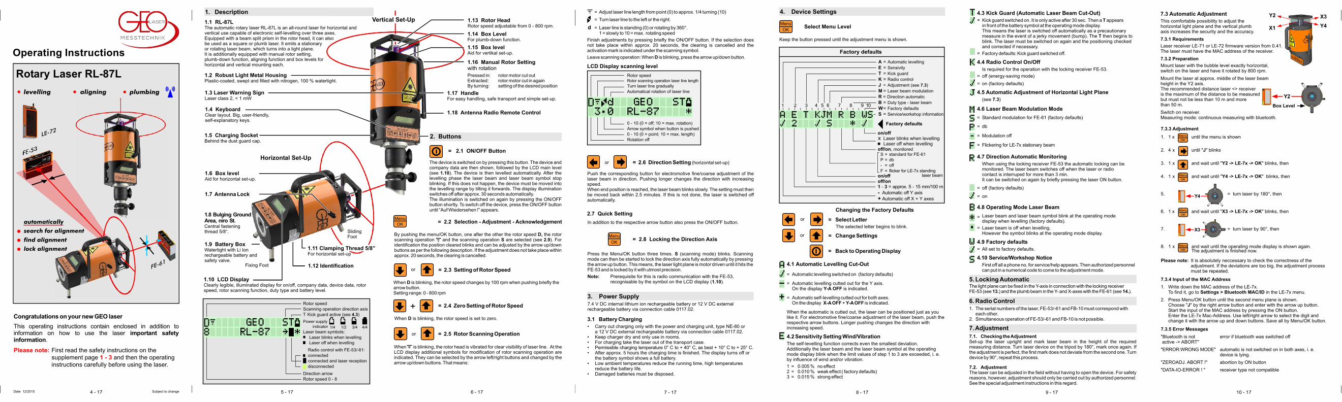
Y4
X3
X1
Y2 X3
Y4
Box Level
Y2
7.3 Automatic Adjustment
This comfortable possibility to adjust thehorizontal light plane and the vertical plumbaxis increases the security and the accuracy.
7.3.1 Requirements
Laser receiver LE-71 or LE-72 firmware version from 0.41.The laser must have the MAC address of the receiver.
7.3.2 Preparation
Mount laser with the bubble level exactly horizontal,switch on the laser and have it rotated by 800 rpm.
Mount the laser at approx. middle of the laser beam height in the Y2 axis.The recommended distance laser <> receiveris the maximum of the distance to be measuredbut must not be less than 10 m and morethan 50 m.
Switch on receiver. Measuring mode: continuous measuring with bluetooth.
Rotary Laser RL-87L
plumbingaligninglevelling
53FE-
FE 61-
EL2-7
automatically
search for alignment
find alignment
lock alignment
Date 12/2015 Subject to change

11 - 1712 - 17 13 - 17 14 - 17 15 - 17 16 - 17 17 - 17
Functions
14.1 Measuring Receiver
The laser receiver FE-61 receives a stationary or rotating plumb laser beam and indicates its position to the light plane by double indication of LEDs.
14.2 Locking Receiver for the Plumb-Axis
It automatically directs the stationary or rotating plumb laser beam to the centre position of the lasers and locks it there. Accuracy to ± 1mm/100 m.
14.3 Receiver Description
X1
X3
Y4
Y2
1X
X 3
Y
2
Y
4
14.6 Outstanding Technical Specifications:
Accuracy measuring receiver: . . . . . . . . . . . . . . . . . . . . . . . . . . . . . to ± 0.1 mmAccuracy locking automatic: . . . . . . . . . . . . . . . . . . . . . . . . . . . to ± 1 mm/100 m
Signal tone: . . . . . . . . . . . . . . . . . . . . . . . . . . . . . . . . . . . . . . . . . . loud, quiet or off
Power supply: . . . . . . . . . . . . . . . . . . . . . 2 x round cell/AA (battery or rech. battery)Current consumption: . . . . . . . . . . . . . approx. 100 mA (operating time to 20 hours)Housing:. . . . . . . . . . . . . . . . . . . . . . . . . . . . . . . . . watertight, except battery coverDimensions / weight: . . . . . . . . . . . . . . . . . . . . . . . . . 140 x 100 x 32 mm / 0.52 kg
Frequency range:. . . . . . . . . . . . . . . . . . . . . . . . . . . . . . . . . . . . 2.4 Ghz ISM BandTransmission power : . . . . . . . . . . . . . . . . . . . . . . . . . . . . . . . . < 100 mW (EIRP)
Guarantee: . . . . . . . . . . . . . . . . . . . . . . . . . . . . . . . . . . . . . . . . . . . . . . 24 monthsCE: . . . . . . . . . . . . . . . . . . . . . . . . . . . . . . . . . . . . . . . . . . . . . . . . . . . . . . certified
Reception: . . . . . . . . . . . . . . . . laser (633 - 815 nm homogeneous beam profile). . . . . . . . . . . . . . . . . . . . . . . . . . . . . . . . . . . . . . . Ø von 5 - 20 mm, 0.8 - 2 mW
Range . . . . . . . . . . . . . . . . . . . . . . . . . . . . . . 2 to 100 mdepending on laser typeDistance to illuminants and high-voltage power lines: . . . . . . . . . . . . . . . > 1.5 m
Conformity with national regulations:GEO-Feinmechanik GmbH herewith declares that the FE-61 conforms to the fundamental requirements and other relevant regulations of directive 1999/5/EG. The declaration of conformity can be found at the following address: http://www.geo-laser.de. In countries with national regulations that are not covered by European directives the operator must himself check the provisions and permits for use.The permit for use is only valid for use with antenna of up to 3 dBi.
No. Order No. Type Description
- 0085.03 LM5 Laser Messfix S, 5 m- 1001.03 TN21 Flexi rod 2.6 m- 8040.01 Floor support for flexi rod TN21- 1005.12 TNL5 Telescopic levelling rod, 5 m- 1021.09 FS-23 Al tripod, min. 1.05 m, max. 1.70 m- 1021.21 FS-30L Al crank tripod, min. 0.95 m, max. 2.85 m- 0059.06.1 ST-10 Al crank tripod, min. 0.55 m, max. 0.94 m- 0059.01.1 ST-20 Al crank tripod, min. 0.93 m, max. 1.99 m- 0059.11.1 ST-30 Al crank tripod, min. 1.18 m, max. 3.00 m
= lock automaticallyA1 x briefly = The radio link with the laser is set up.
Once the rotating plumb beam hits the measuring quadrant of the receiver it is automatically directed to the center and fixed there. By slowly moving the laser receiver, the position of the light surface is changed. The reception is indicated by symbols on laser and LEDs on receiver.LEDs blink alternately right and left: centre found and locked, the setting phase
is completed
Switch off receiver to switch off the locking function.
= tone loud, quiet or off
1 x briefly = switch on: The FE-61 works as measuring receiver.
1 x long = switch off
Keep the button pressed until the LED of the operating mode display lights accompanied by a tone sequence or automatically after 15 min. without .
Switch on the FE-61 and move it to the laser light plane until the reception of the light plane is indicated by LEDs and signal tones.To receive the required accuracy, move the FE-61 in arrow direction.
reception
= switch on
14.5 Operation
Remote Control
It is possible to adjust manually the direction and height of the laser with the FE-61.
To activate the remote control when turning on the receiver press the power button until the remote LED flashes.
The side (Y axis) can be adjusted with the keys next to the LED.
Switch to the height (X axis) by briefly pressing the power button. The remote control LED blinks faster.Now the height can be adjusted using the buttons next to the LED.
Press briefly to return to the measuring receiver function.
10. Technical Specifications RL-87L
Laser class: . . . . . . . . . . . . . . . . . . . . . . . . . . . . . . . . . . . . . . . . . . . . . . . . . . . 2Output power plumb and rotating beam: . . . . . . . . . . . . . . . . . . . < 1 mW eachLaser type: . . . . . . . . . . . . . . . . . . . . . . . . . . . . . . . . . diode, visible red, 635 nmBeam diameter: . . . . . . . . . . . . . . . . . . . . . . . . . . . . . . . . . . . . . at laser 13 mmRange depending on circumstances: . . . . . . . . . . . . . . . . . to 200 m, 00 m
Automatic function: . . . . . . . . . . . . . . . . . . . . . . . . . . . . . horizontal and verticalAutomatic function can be switched off: . . . . . . . . yes, either one or both axesRotor speed: . . . . . . . . . . . . . . . . . . adjustable: 0, 100, 200, 300, 600, 800 rpm
Self-levelling range: . . . . . . . . . . . . . . . . . . . . . . . . . . . . . . . . . . . . . . . . . ± 5 %Direction setting: . . . . . . . . . . . . . . . . . . . . . . . . . . . . . . . . . . . . . . . . . . . . ± 5 %Permissible deviation: . . . . . . . . . . . . . . . . . . . . . . . . . . . . . . . . . ± 5 mm/100 m
Automatic locking of laser light plane: . . . . to 200 m via locking receiver FE-53Automatic locking of plumb beam: . . . . . . to 100 m via locking receiver FE-61
: . . . . . . . . . . .
External power supply: . . . . . . . . . . . . . . . . . 11 to 14 V DC with cable 0117.02Low battery cut-out:. . . . . . . . . . . . . . . . . . . . . . . . . . . . . . . . . . . . . . . . . . . . yes
Watertight: . . . . . . . . . . . . . . . . . . . . . . . . . . . . . . . . . . . . . . . . . . . . . . . to 3.5 mTemperature range: . . . . . . . . . . . . . . . . . . . . . . . . . . . . . . . . - 10° C to + 50° CWeight: . . . . . . . . . . . . . . . . . . . . . . . . . . . . . . . . . . . . . . . . . . . . . . . . . . . 3.4 kgAdjustment: . . . . . . . . . . possible in the field without having to open the device
Guarantee: . . . . . . . . . . . . . . . . . . . . . . . . . . . . . . . . . . . . . . . . . . . . . 24 monthsCE: . . . . . . . . . . . . . . . . . . . . . . . . . . . . . . . . . . . . . . . . . . . . . . . . . . certified
Frequency range: . . . . . . . . . . . . . . . . . . . . . . . . . . . . . . . . . 2.4 Ghz ISM BandTransmission power : . . . . . . . . . . . . . . . . . . . . . . . . . . . . . . . < 100 mW (EIRP)
Ø 4
Operating time with 7.4 V DC Li Ion recharg. battery to 28 hours
Conformity with national regulations:GEO-Feinmechanik GmbH herewith declares that the devices RL-87L, FE-53, FE-61 and FB-10 conform to the fundamental requirements and other relevant regulations of directive 1999/5/EG. The declaration of conformity can be found at the following address: http://www.geo-laser.de. In countries with national regulations that are not covered by European directives the operator must himself check the provisions and permits for use.The permit for use is only valid for use with antenna of up to 3 dBi.
No. Order No. Type Description
1 2 0037.18 Power supply/Battery charger 3 Transport case
with standard delivery package
0001.675 RL-87L Rotary Laser NE-80
0077.36
1- 3 0001.675.1 RL-87L
1 2 3
No. Order No. Type Description
Laser receiverLaser receiver
3 0009.36.1 FE-53 Locking receiver for laser light plane4 Locking receiver for plumb beam
5 0026.07 FB-10 Two-way radio remote control 6
7 0061.01.2 BW-80 Base plate/Wall mount8 0122.01.1 ST-05 Facade mounting system
1 1035.27 Storm with digital data display 2 0009.39.1 LE-72 with digital data display
0009.70.1 FE-61
0117.02 12 V DC Li Ion connection cable
11. Standard Delivery Package
12. Optional Accessories
8. Troubleshooting
1. No laser beam - check battery charge.2. Low range - clean laser beam exit window.3. Laser beam blinks slowly - move device into the levelling range by tilting
forwards.4. Laser beam and banking arrows blink slowly - reset laser from the limitation.
If the errors of points 3 and 4 are not corrected within 2.5 minutes, the deviceis switched off automatically.
5. Laser switched off automatically (kick guard or direction automaticmonitoring) - Switch on l
6. Rotor does not rotate: Manual rotor setting: extract knob by turning it aser beam by pressing the ON button shortly.
(see 1.16).
9. MaintenanceThe laser requires no special maintenance. Keep the electrical connections clean. Do not clean with water spray. Clean glass parts with a soft, clean cloth. Store dry. Always transport the laser in its original case.
13.6 Outstanding Technical Specifications:
Accuracy direction automatic: . . . . . . . . . . . . . . . . . . . . . . . . . . to ± 1 mm/100 mAccuracy receiver: . . . . . . . . . . . . . . . . . . . . . . . . . . . . . . . . ± 1 mm or ± 0.1 mmReception range/-angle:. . . . . . . . . . . . . . . . . . . . . . . . . . . . . . . . 85 mm / > 100°Rotor speed: . . . . . . . . . . . . . . . . . . . . . . . . . . . . . . . . . . . . . . . . . . 300 - 800 rpmSignal tone: . . . . . . . . . . . . . . . . . . . . . . . . . . . . . . . . . . . . . . . . . . loud, quiet or off
Power supply: . . . . . . . . . . . . . . . . . . . . . 2 x round cell/AA (battery or rech. battery)Current consumption: . . . . . . . . . . . . . approx. 100 mA (operating time to 20 hours)Housing:. . . . . . . . . . . . . . . . . . . . . . . . . . . . . . . . . watertight, except battery coverDimensions / weight: . . . . . . . . . . . . . . . . . . . . . . . . . 140 x 100 x 32 mm / 0.52 kg
Frequency range:. . . . . . . . . . . . . . . . . . . . . . . . . . . . . . . . . . . . 2.4 Ghz ISM BandTransmission power : . . . . . . . . . . . . . . . . . . . . . . . . . . . . . . . . < 100 mW (EIRP)
Guarantee:. . . . . . . . . . . . . . . . . . . . . . . . . . . . . . . . . . . . . . . . . . . . . . 24 monthsCE: . . . . . . . . . . . . . . . . . . . . . . . . . . . . . . . . . . . . . . . . . . . . . . . . . . . . . . certified
Range depending on laser type: . . . . . . . . . . . . . . . . . . . . . . . . . . . . 2 to 200 mDistance to illuminants and high-voltage power lines: . . . . . . . . . . . . . . . > 1.5 m
Conformity with national regulations:GEO-Feinmechanik GmbH herewith declares that the FE-53 conforms to the fundamental requirements and other relevant regulations of Directive 1999/5/EG. The declaration of conformity can be found at the following address: http://www.geo-laser.de. In countries with national regulations that are not covered by European directives the operator must himself check the provisions and permits for use.The permit for use is only valid for use with antenna of up to 3 dBi.
Apart from the ON button, the functions correspond to those of the keyboard and display of the laser.
Note: It is not possible to switch on the laser and the radio transmission and to switch off the laser by the FB-10.
15. Wireless Control FB-10
15.1 Functional Description
The remote control FB-10 allows a wireless operation of GEO lasers with radio module. Laser and receiver have the same keyboards, operating mode displays, radio transmitters and receivers.Range while visual contact up to 350 m.
15.2 Device Description
15.3 Button Description (see 2.)
= ON only FB-10
1 x short = ON: The message "Try to connect .. Please wait .." appearsand the remote control connects to the GEO laser within approx. 20 seconds.
1. x long = laser beam + rotor switched off (stand-by mode)
2. x long = laser beam + rotor switched on again
Note: Press the button until the desired symbol or appears.
OFF = Auto off after approx. two minutes if no buttons pressed.
Robust Metal Housing: plastic-coated, 100 % watertight.
15.4 Error Messages:
"Connection Lost!": Communication between laser and remote control interrupted - establish visual contact with the laser or reduce the distance to the laser.Activate wireless remote control in the menu of the GEO laser (see instructions for use of laser).
"BATTERY LOW": Replace batteries soon.The LCD light stays off to save power.
"BATTERY EMPTY!": The batteries must be replaced immediately.
Note: The radio transmission can be switched off either in the second menu level of the laser or of the remote control. A renewed switch-on of the radio transmission is possible only at the laser.
LCD-DisplayClearly legible, illuminated display
Battery Compartment LidTo open in direction of arrow. When inserting the battery observe the correct polarity.
Antenna
Antenna Lock
KeyboardEasy to handle, clear layout, user-friendly.
14.4 Control Principle
14. Locking and Receiver FE-61Measuring
Robust Metal HousingPlastic-coated, watertight.M5 mounting thread at the back of the housing.
Power Indicator:LED blinks slowly = device switched onLED blinks quickly = battery almost
emptyLED off = device switched off
Battery
Compartment LidTo open in direction of arrow.Make sure the polarity is correct when installing the new battery.
Locking Receiver:
Measuring Receiver:
LED blinks = device switched onLED off = device switched off
Operating Mode Display
LED blinks = Radio control dial-upLED off = Radio control connectedLED on = Radio control failure
Remote Control DisplayY axis: LED blinks slowlyX axis: LED blinks quickly
Orientation Notches
Measuring Quadrantwith solar cells sensor and LED display
Table of Contents Page
Safety Information . . . . . 1 - 2
Laser safety . . . . . . . . 2 - 3
Repair . . . . . . . . . . . . . 3
EMC . . . . . . . . . . . . . 3
Guarantee . . . . . . . . . . 3
Disposal. . . . . . . . . . . . 3
1. Laser Description . . . . . 5 - 6
2. Buttons 6 - 7
3. Power Supply . . . . . . . . 7
4. Device settings . . . . . . 8 - 9
5. Locking Automatic . . . . . . 9
S1
S2
S3
S4
S4
S5
. . . . . . . . . .
Page
9
9 - 10
11
Maintenance
11. . 12
12. . . . . 12
13. . 13 - 14
14.
15. Wireless Control FB-10 . . . 17
6. Radio Control . . . . . . . . .
7. Adjustment . . . . . . . .
8. Troubleshooting . . . . . . .
9. . . . . . . . . . 11
10. Technical Specifications . . . 11
Laser Receiver FE-53
Laser Receiver FE-61 . . 15 - 16
Standard Delivery Package
Optional Accessories
1 2 3 4 5 76 8
13. Locking and Measuring Receiver FE-53
Functions
13.1 Laser Receiver
. Accuracy approx. 1 resp. mm.
13.2 Locking Receiver for the Y-axis (Direction)
The laser receiver type FE-53 receives a rotating laser or diode laser beam and indicates its position to the light plane by way of two resp. three LEDs and various signal tones
The rotating laser beam is received by the locking receiver FE-53 and then automatically directed to the position fixed before. Deviations are detected and corrected immediately. Accuracy to
± ± 0,1
± 1mm/100 m.
13.3 Receiver Description
Robust Metal HousingPlastic-coated, watertight.M5 mounting thread at the back of the housing.
Power Indicator:LED blinks slowly = device switched onLED blinks quickly = battery almost emptyLED off = device switched off
Battery
Compartment LidTo open in direction of arrow. Make sure the polarity is correct when installing the new battery.
Locking Receiver
Meas. Receiver ± 0.1 mm Meas. Receiver ± 1 mm
LED + slow tone sequence
LED + quick tone sequence
LED + steady tone = middle
LED + Tone alternating = middle
Locking Receiver:
Meas. Receiver:
LED blinks = device switched onLED off = device switched off
Operating Mode Display
LED blinks = Radio control dial-upLED off = Radio control connectedLED on = Radio control failure
6
laser beam
13.4 Control Principle
The FE-53 can be mounted either on the left or on the right side of the laser. Because of reasons of functionality, the keyboards of both devices must be on the same side.
YY
13. Locking and Measuring Receiver FE-53
switch over from measuring to locking receiver:search, find and lock automatically
13.5 Operation
A
1. x briefly = The radio link with the laser is set-up and the laser light plane is directed to the centre of the receiver and locked there automatically. As soon as the rotating laser beam hits the arrow range of the receiver, it is automatically directed to the middle and locked there. The direction of the laser light plane can be changed by slowly moving the laser receiver. The reception is indicated by a symbol at the laser and LEDs at the receiver:
- LEDs blink simultaneously right and left > laser searches for receiver - LED blinks right or left > receiver found- LEDs blink alternately right and left > setting finished:
centre found and locked
2. x briefly = laser searches for the receiver again.
Switch off receiver to switch off the locking function.
1. x briefly = Measuring receiver with an accuracy of +/- 1 mm.Move FE-53 towards the light plane until the reception of the light plane is indicated by LED and signal tone.To reach the desired accuracy move the FE-53 in arrow direction:Accuracy: One LED blinks in the middle = +/- 1 mm
2. x briefly = Measuring receiver with an accuracy of +/- 0.1 mmAccuracy: Two LED's blink alternately = +/- 0.1 mm
3. x briefly = Back to measuring receiver with an accuracy of +/- 1 mm.
1 x long = Switch offPress button until the LED of the operating mode display flashes accompanied by a tone sequence or automatically after 15 min. without reception.
=
= tone loud, quiet or off
= switch on/off
GEO-Laser GmbHSolinger Str. 845481 Muelheim an der RuhrGermany
Phone +49 208 99357-0Fax +49 208 [email protected]
GEO - partner of the construction industry for 50 years

![S A OPE 19 U A E 19 OPE 196 T · 2020-03-09 · A I SP L A S A U A E OPE 9HQH]XHOD OPE OPE OPE T T T A I IR I SP L A N U A E S A 196 191 199 196 2000 196 19 196 200 19 OPE 196 P E](https://img.pdfslide.us/doc/110x75/5eb193773ed8566dce459833/s-a-ope-19-u-a-e-19-ope-196-t-2020-03-09-a-i-sp-l-a-s-a-u-a-e-ope-9hqhxhod-ope.jpg)