Embed Size (px)
Citation preview

U S B
A c c e l # 1A c c e l # 2I R S e n s o r
Se
lec
t
# 1
# 2
www.DynexHobby.com
This manual and a proportion of its content is copyright of © DynexHobby 2020. All rights reserved.

1 | P a g e © C o p y r i g h t D y n e x H o b b y 2 0 2 0
High speed rotors contain enough energy to cause damage to people and
property. Manufacturer’s safety precautions MUST be adhered to during
testing and operation of devices.
Safety goggles must be worn during testing and operation of devices. High
speed rotors can expel high velocity debris during an adverse event.
WARNING!
✓ Never stand in front of or alongside a spinning rotor. Stand behind at a safe distance.
✓ Ensure bystanders are well away from the test article at a safe distance.
✓ NEVER run a rotor at full speed when balancing. Mounting cradles are not designed
to restrain running devices at operational speeds.
✓ Run devices at the slowest possible speeds to avoid injury.
✓ Do not leave loose items nearby that can be caught by a spinning rotor.
✓ Secure all loose cables to prevent being caught in moving parts.
✓ Always stop running devices before working on them.
✓ Never place a limb in front of a rotor to stop it or slow it down.
✓ Fasten devices in secure mounts when operating at full speed. Follow the
manufacturer’s instructions for correct device operation.
✓ Impulse was not designed for full size vehicles or industrial applications.
✓ Due to the high operational speeds, this system is not recommended for gas turbine
engines.
Before you begin
Your safety is your own responsibility, including proper use of equipment and safety gear,
and determining whether you have adequate skill and experience. Improper use of
modeling gear is dangerous, unless used properly and with adequate precautions, including
safety gear. Some illustrative photos do not depict safety precautions or equipment, in
order to show operating instructions more clearly. These products are not intended for use
by children. These products are intended for radio control model applications and should
never be used on industrial equipment.
Use of our products and content on DynexHobby.com is at your own risk. It is your
responsibility to make sure that your activities comply with applicable laws, including
copyright. The United States Fire Administration (USFA) has a guide and many simple steps
you can take to prevent the loss of life and property resulting from electrical fires.

2 | P a g e © C o p y r i g h t D y n e x H o b b y 2 0 2 0
Introduction
Impulse is a combined dynamic balancer and vibration analyzer for hobbyist. It is capable of
balancing rotors and shaft assemblies to reduce wear and improve performance. This
manual outlines the Impulse system.
The Impulse system consists of the following parts. The analyzer is the central processing
unit. It collects and analyses vibration signals for dynamic balancing and spectrum analysis.
Impulse is connected to a PC via a USB cable.
The system includes an accelerometer for measuring the acceleration levels of vibration. An
infra-red detector and strobe light is also available for synchronizing the location of
corrective weights required for balancing.
Impulse Analyzer
USB Mini Cable Accelerometer IR Sensor (Optional)
Laser Module (Optional)
U S B
A c c e l # 1A c c e l # 2I R S e n s o r
Se
lec
t
# 1
# 2
www.DynexHobby.com

3 | P a g e © C o p y r i g h t D y n e x H o b b y 2 0 2 0
Item Quantity
Impulse • USB powered –0.3V to 6.5V
• Dimensions (outer): 10mm(0.25")(H)x30mm(1.2")(W)x67mm(2.6")(L)
• Maximum input voltages Ch1 and Ch2: –0.3V to 4V
• Sampling frequencies (kHz): 8, 11.025, 16, 22.05, 32, 44.1 & 48
• Resolution 8, 16 bits
IR Detector • Dimensions: 0.3" x 0.5" x 0.1"
• Operating voltage: 5.0V
• Supply current: 25mA
• Output format: analog voltage
• Optimal sensing distance: 0.125" (3 mm)
• Maximum recommended sensing distance: 0.25" (6 mm)
Accelerometer (ACC1) • Range: +/- 3g
• Sensitivity: 300 mV/g
• Small, low-profile package
• 1.8 V to 5 V operating range
• 10,000g shock survival
• Excellent temperature stability
• Output Type: Analog
• Typical Bandwidth (kHz): 1.5kHz
• Noise Density (µg/rtHz): 300

4 | P a g e © C o p y r i g h t D y n e x H o b b y 2 0 2 0
Item Function
On Light illuminates when power is applied to Impulse
Select Switch selects between Accelerometer 1 and Accelerometer 2
IR Connection for infra-red reference detector
Accel #1 Accelerometer 1 sensor
Accel #2 Accelerometer 2 sensor (optional)
USB USB cable connector
U S B
A c c e l # 1A c c e l # 2I R S e n s o r
Se
lec
t# 1
# 2
www.DynexHobby.com
USB
Select
On LED
IR Sensor Accelerometer 2 Accelerometer 1

5 | P a g e © C o p y r i g h t D y n e x H o b b y 2 0 2 0
The diagram below illustrates the typical connections for the Impulse system.
USB CABLE: Impulse communicates to a PC via a USB cable which is connected to a spare
USB port. The USB cable can be connected at any time, however the cable must be
connected when performing balancing or vibration spectrum analysis.
ACCELEROMETER 1: Must be connected to Accel #1. Accelerometer 1 is used for plane 1
during balancing.
ACCELEROMETER 2: Must be connected to Accel #2. Accelerometer 2 is used for plane 2
during two plane balancing.
IR SENSOR: Must be connected to the IR port. The IR Sensor is used during balancing only. It
is not required for the “Strobe Balancing Method”.
U S B
A c c e l # 1A c c e l # 2I R S e n s o r
Se
lec
t
# 1
# 2
www.DynexHobby.com
Accelerometer 1
IR Detector
Accelerometer 2
PC

6 | P a g e © C o p y r i g h t D y n e x H o b b y 2 0 2 0
ADDITIONAL NOTES
The arrow above indicates the sensor direction. The accelerometer will sense
motion only along this axis.
Mounting the Accelerometers.
The following diagram illustrates the connection of sensors to Impulse. The power pin can
provide +5V to sensors and external devices. If connecting devices that are powered
externally, disconnect the power pin to Impulse. Failure to do so may damage Impulse!
Install the accelerometer on the rotor suspension system. It is best to install it in a
horizontal position. The accelerometer can be positioned at any angle as desired, however
the full scale deflection can be limited.
The smooth side is positioned downward and glued to the device under test. Experiments
have shown that attaching the accelerometer using “Blu-tack” is adequate.
Wire Designation
• Black - Ground (GND)
• Red - Power (+)
• White - Signal
CAUTION!
Black
Red
White

7 | P a g e © C o p y r i g h t D y n e x H o b b y 2 0 2 0
1. Secure any loose cables to the device using “Blu-tack” or tape. This will prevent
cables from getting caught in the spinning rotor and reduces mechanical noise during
testing.
2. Do not install any part of Impulse to moving or rotating parts.

8 | P a g e © C o p y r i g h t D y n e x H o b b y 2 0 2 0
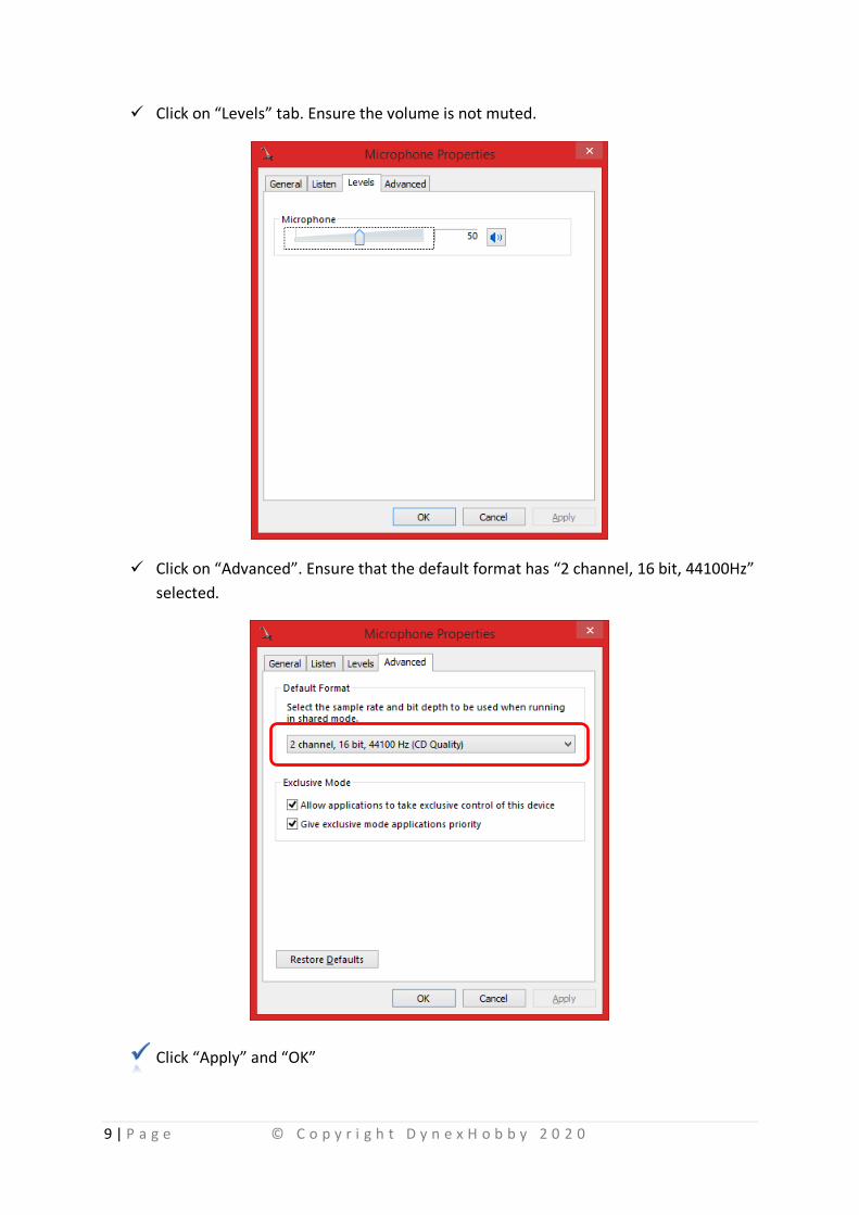
The Impulse requires configuration in Windows. The following method illustrates the
preferred setup method.
✓ Open “Control Panel” in Windows. Click on “Sound” to open the available sound
devices.
✓ Click on the “Recording” tab and double click on the recording device that Impulse is
connected to. e.g. Microphone.
9 | P a g e © C o p y r i g h t D y n e x H o b b y 2 0 2 0
✓ Click on “Levels” tab. Ensure the volume is not muted.
✓ Click on “Advanced”. Ensure that the default format has “2 channel, 16 bit, 44100Hz”
selected.
Click “Apply” and “OK”

10 | P a g e © C o p y r i g h t D y n e x H o b b y 2 0 2 0
Introduction
DynexHobby provides analysis tools to determine the balance of rotors. There are two tools
available listed below. These can be downloaded from www.dynexhobby.com.
Name Image Application
Dynex Analysis
Used for all balance methods. This application runs under Microsoft Windows. Note that .NET 4 must be installed for this application to function.
Scope Tool
The scope tool can be used as an alternative to the Dynex Analysis package. It has a few additional features such as signal generation and vibration recording. This program is now superseded.
11 | P a g e © C o p y r i g h t D y n e x H o b b y 2 0 2 0
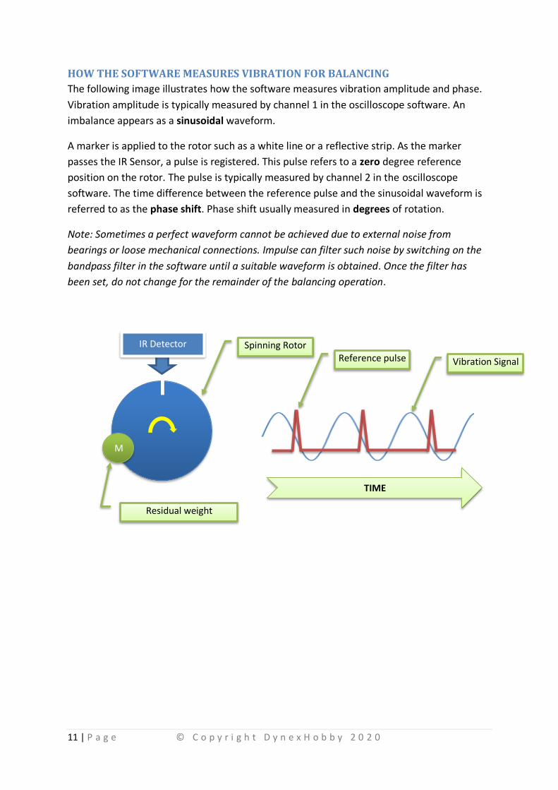
HOW THE SOFTWARE MEASURES VIBRATION FOR BALANCING
The following image illustrates how the software measures vibration amplitude and phase.
Vibration amplitude is typically measured by channel 1 in the oscilloscope software. An
imbalance appears as a sinusoidal waveform.
A marker is applied to the rotor such as a white line or a reflective strip. As the marker
passes the IR Sensor, a pulse is registered. This pulse refers to a zero degree reference
position on the rotor. The pulse is typically measured by channel 2 in the oscilloscope
software. The time difference between the reference pulse and the sinusoidal waveform is
referred to as the phase shift. Phase shift usually measured in degrees of rotation.
Note: Sometimes a perfect waveform cannot be achieved due to external noise from
bearings or loose mechanical connections. Impulse can filter such noise by switching on the
bandpass filter in the software until a suitable waveform is obtained. Once the filter has
been set, do not change for the remainder of the balancing operation.
M
IR Detector
Reference pulse Vibration Signal
TIME
Spinning Rotor
Residual weight

12 | P a g e © C o p y r i g h t D y n e x H o b b y 2 0 2 0
Introduction
Unbalanced rotors have relatively high force effects on bearings. High levels of unbalance
can cause vibration, deformation, power degradation, friction and can degrade service life.
In the case of a rotating shaft, the unbalance causes periodical forces to the suspension
system which corresponds to the rotational speed. In other words it is synchronous with
rotational speed (first order). In order to balance the rotor the correct running speed should
be selected in the balancing instrument. The test speed is usually much lower than the
operational speed for safety reasons. The correct running speed reduces the disturbance
caused by the noise, harmonics, bearings and blade frequencies.
The unbalance is radial in their line of action and it is a vector quantity. A vector has both
magnitude and direction. The direction can be characterized by the phase between the
unbalance vector (from the center of the shaft) and a vector to the reference point at the
shaft (from the center of the shaft).
Static Unbalance
The general dynamic unbalance consists of the static (single plane) unbalance. This is when
the mass center line is parallel and not coincidental with the rotational axis. This kind of
balance exists in disk shape structures. It can be eliminated by a compensating weight. This
method is appropriate for balancing ducted fan units, wheels or any disc shaped rotors.
Coupled Unbalance
The other type of unbalance is when a pair of weights are at two ends of the shaft but on
opposite sides to each other (180°). The rotor is in static balance, but the centrifugal forces
will produce a moment about the center of mass when the rotor turns. In this case, only a
couple unbalance exists. The mass center line crosses the shaft axes at the center of gravity.

13 | P a g e © C o p y r i g h t D y n e x H o b b y 2 0 2 0
The couple unbalance can be compensated by two weights, which are positioned to
counteract the couple unbalance at two planes. The ideal balancing task is to reduce the
inhomogeneous mass distribution caused forces by adding or removing weights along the
shaft.
To perform balancing, refer to DynexHobby’s Balancing Methods Manual.

14 | P a g e © C o p y r i g h t D y n e x H o b b y 2 0 2 0
SUSPENSION SYSTEM (MOUNTING CRADLE)
The suspension system or the mounting cradle is crucial for single or double plane
balancing. The cradle allows the rotor system to oscillate back and forth near its natural
state. The oscillation is important for Impulse to sense vibration and analyze the imbalance.
Note: Mounting cradles are not supplied by DynexHobby. Cradles can easily be made from
components supplied by your local hardware or electronics store. Sample cradles are shown
below.

15 | P a g e © C o p y r i g h t D y n e x H o b b y 2 0 2 0
Each suspension system has a natural mode of vibration or natural frequency. If tests are
conducted at the natural frequency (a specified RPM that cause’s natural vibration of the
system), then the balancing results will be difficult to achieve.
To avoid this, the following recommendations should be considered:
• Run balancing at speeds above or below the natural frequency. This would be in a
region where phase angle and amplitude are flat in the charts above.
• Soft suspension construction to provide a low resonance frequency.
• Allow the cradle to rock smoothly using frictionless supports. Teflon bearings or
magnetic supports are ideal.
• Provide additional damping to reduce overshoot of the cradle. Foam rubber works
well.
• Mechanically isolate the suspension system from the bench. This can be achieved by
using a rubber mat.

16 | P a g e © C o p y r i g h t D y n e x H o b b y 2 0 2 0
DETERMINING THE SUSPENSION SYSTEM NATURAL FREQUENCY
METHOD 1
The following is a method for identifying the suspension system natural frequency.
✓ Mount rotor in cradle.
✓ Run motor incrementally from the lowest possible RPM to the highest safest speed.
Please ensure safety when operating the rotor and follow manufacturer’s
instructions. Protective gear is recommended.
✓ Plot the vibration amplitude and phase angle with incremental RPM.
✓ The natural frequency is identified by the peak in the vibration amplitude.
A sample of the Impulse suspension system is shown below. The ideal running speed would
be above 40Hz.

17 | P a g e © C o p y r i g h t D y n e x H o b b y 2 0 2 0
METHOD 2
The following method is simple and generally used by DynexHobby.
✓ Open the “Scope” software and click on the “frequency” tab.
✓ Click on “peak hold”.
✓ With your rotor at rest on the cradle and sensor attached, quickly tap the cradle
support with a tap hammer. A light tap is all that is needed.
The peak frequency generated is your cradles natural frequency, example below. Generally
DynexHobby cradles are around 20~30Hz, so balancing can be carried out about 40~60Hz.

18 | P a g e © C o p y r i g h t D y n e x H o b b y 2 0 2 0
The Impulse is capable of being used as a 2 channel oscilloscope. To start using this function
start the “Scope” program and select the Impulse audio device.
Connect a signal source to the signal pins ensuring the ground pin is also connected. Note
that Impulse can also supply +5V to your signal source if required. If your source signal has
its own power supply, do not feed power back into Impulse as it will damage the circuitry.
The following example demonstrates connectivity between a signal source and Impulse.
The scope software has the same tool set as seen in many commercial oscilloscopes.
U S B
A c c e l # 1A c c e l # 2I R S e n s o r
Se
lec
t
# 1
# 2
www.DynexHobby.com

19 | P a g e © C o p y r i g h t D y n e x H o b b y 2 0 2 0
Introduction
Impulse is an AC coupled device which is optimized to measure vibration signals. As a result
Impulse is not capable of measuring DC voltage level signals.
Whilst measuring square wave signals, a slight decay in the peak voltage may occur when
the pulse width is significantly large. However this will not present a problem for most
general applications.
1. Do I need the IR Sensor or Laser Module to conduct balancing?
a. These sensors are only required if performing Single Plane or 2 Plane
balancing. These sensors are not required for 4 Point or propeller balance
methods.
2. The Impulse shows Channel 1 but not Channel 2? Why?
a. Impulse must be set to 2 Channel, 16 bit, 44100Hz in Windows setup.
3. How can I tell if the Impulse input ports are working?
a. Connect the accelerometer to all ports. Shake the accelerometer by hand. If a
signal that looks like a wave appear appears in the Scope software, then the
Impulse is working correctly.
4. What colour mark do I need to place on the rotor to detect RPM?
a. Any contrasting colour will work. For example
i. On an aluminum rotor, a black marker is sufficient.
ii. On a black rotor, a white paint mark is sufficient.
5. Device drivers are not installing for Impulse. Why?
a. Windows automatically detects Impulse and installs the correct driver. Check
that the firewall isn’t blocking drivers. Under certain circumstances, special
Windows installations may require enabling sound devices for Impulse to
work.
6. My RPM readings jump around a lot when IR Sensor is selected in software. Why?
a. The IR and Laser sensors are used to detect accurate RPM. The sensors use
light reflected off a surface to detect speed. The relative position of these
sensors will ensure correct readings.
i. For IR sensor ideal position is 3-5mm from marker.
ii. For Laser Sensor ideal position is 100mm from marker.
iii. Note: Direct sunlight can affect measurements.
7. How do I measure the balance weights?
a. Use a Jewelers Scale with 0.001g accuracy.
8. What is the minimum speed I can run Impulse?

20 | P a g e © C o p y r i g h t D y n e x H o b b y 2 0 2 0
a. 1320RPM.
9. What direction should the accelerometers be mounted for 2 plane balancing?
a. The sensors must be mounted in the same orientation for Plane 1 and 2.

21 | P a g e © C o p y r i g h t D y n e x H o b b y 2 0 2 0
TERMS & CONDITIONS
PLEASE READ THE FOLLOWING TERMS AND CONDITIONS OF USE CAREFULLY BEFORE USING DynexHobby.com. All users of this site agree
that access to and use of this site are subject to the following terms and conditions and other applicable law. If you do not agree to these
terms and conditions, please do not use this site.
COPYRIGHT
The entire content included in this site, including but not limited to text, graphics or code is copyrighted as a collective work under
copyright laws, and is the property of DynexHobby.com. The collective work includes works that are licensed to DynexHobby.com.
Copyright 2012, DynexHobby.com ALL RIGHTS RESERVED. Permission is granted to electronically copy and print hard copy portions of this
site for the sole purpose of placing an order with DynexHobby.com or purchasing DynexHobby.com products. You may display and, subject
to any expressly stated restrictions or limitations relating to specific material, download or print portions of the material from the different
areas of the site solely for your own non-commercial use, or to place an order with DynexHobby.com or to purchase DynexHobby.com
products. Any other use, including but not limited to the reproduction, distribution, display or transmission of the content of this site is
strictly prohibited, unless authorized by DynexHobby.com. You further agree not to change or delete any proprietary notices from
materials downloaded from the site.
TRADEMARKS
All trademarks, service marks and trade names of DynexHobby.com used in the site are trademarks or registered trademarks of
DynexHobby.com
WARRANTY DISCLAIMER
This site and the materials and products on this site are provided "as is" and without warranties of any kind, whether express or implied.
To the fullest extent permissible pursuant to applicable law, DynexHobby.com disclaims all warranties, express or implied, including, but
not limited to, implied warranties of merchantability and fitness for a particular purpose and non-infringement. DynexHobby.com does not
represent or warrant that the functions contained in the site will be uninterrupted or error-free, that the defects will be corrected, or that
this site or the server that makes the site available are free of viruses or other harmful components. DynexHobby.com does not make any
warrantees or representations regarding the use of the materials in this site in terms of their correctness, accuracy, adequacy, usefulness,
timeliness, reliability or otherwise. Some states do not permit limitations or exclusions on warranties, so the above limitations may not
apply to you.
DEFECTIVE MERCHANDISE
All defective merchandise from DynexHobby.com must be returned directly to us. An email must be sent to us informing us of defective
items. All defective products can be returned for exchange under the following conditions: Merchandise must be returned in its original
package within 30 days from the date of purchase. Do not write on the package. We will not exchange or refund any product with the
product package having "defective" or anything else written on it. Returned items must be in resale condition, with the original packing
material, unopened with all shipped items included.
LIMITATION OF LIABILITY
DynexHobby.com products are not toys nor intended to be used with a toy. All safety precautions recommended by manufacturers MUST
be adhered to.
DynexHobby.com shall not be liable for any special or consequential damages that result from the use of, or the inability to use, the
materials on this site or the performance of the products, even if DynexHobby.com has been advised of the possibility of such damages.
Applicable law may not allow the limitation of exclusion of liability or incidental or consequential damages, so the above limitation or
exclusion may not apply to you.
TYPOGRAPHICAL ERRORS
In the event that a DynexHobby.com product is mistakenly listed at an incorrect price, DynexHobby.com reserves the right to refuse or
cancel any orders placed for product listed at the incorrect price. DynexHobby.com reserves the right to refuse or cancel any such orders
whether or not the order has been confirmed and your credit card charged. If your credit card has already been charged for the purchase
and your order is cancelled, DynexHobby.com shall issue a credit to your credit card account in the amount of the incorrect price.
TERM; TERMINATION
These terms and conditions are applicable to you upon your accessing the site and/or completing the registration or shopping process.
These terms and conditions, or any part of them, may be terminated by DynexHobby.com without notice at any time, for any reason. The
provisions relating to Copyrights, Trademark, Disclaimer, Limitation of Liability, Indemnification and Miscellaneous, shall survive any
termination.
NOTICE
DynexHobby.com may deliver notice to you by means of e-mail, a general notice on the site, or by other reliable method to the address
you have provided to DynexHobby.com.

22 | P a g e © C o p y r i g h t D y n e x H o b b y 2 0 2 0
PARTICIPATION DISCLAIMER
DynexHobby.com does not and cannot review all communications and materials posted to or created by users accessing the site, and is
not in any manner responsible for the content of these communications and materials. You acknowledge that by providing you with the
ability to view and distribute user-generated content on the site, DynexHobby.com is merely acting as a passive conduit for such
distribution and is not undertaking any obligation or liability relating to any contents or activities on the site. However, DynexHobby.com
reserves the right to block or remove communications or materials that it determines to be (a) abusive, defamatory, or obscene, (b)
fraudulent, deceptive, or misleading, (c) in violation of a copyright, trademark or; other intellectual property right of another or (d)
offensive or otherwise unacceptable to DynexHobby.com in its sole discretion.
INDEMNIFICATION
You agree to indemnify, defend, and hold harmless DynexHobby.com, its employees, agents, licensors and suppliers (collectively the
"Service Providers") from and against all losses, expenses, damages and costs, including reasonable attorneys' fees, resulting from any
violation of these terms and conditions or any activity related to your account (including negligent or wrongful conduct) by you or any
other person accessing the site using your Internet account.
THIRD-PARTY LINKS
In an attempt to provide increased value to our visitors, DynexHobby.com may link to sites operated by third parties. However, even if the
third party is affiliated with DynexHobby.com, DynexHobby.com has no control over these linked sites, all of which have separate privacy
and data collection practices, independent of DynexHobby.com. These linked sites are only for your convenience and therefore you access
them at your own risk. Nonetheless, DynexHobby.com seeks to protect the integrity of its web site and the links placed upon i t and
therefore requests any feedback on not only its own site, but for sites it links to as well (including if a specific link does not work).
RETURNS
When you using our website, and in a case of returned goods, you have to wrap it and pack it the best as possible, and you wi ll held the
responsibility of the package condition when it arrives back to us. We will NOT accept broken goods returned, that was broken while the
shipment, or new item returns in a bad condition. We may apply 20% restocking fee for returned goods.