Embed Size (px)
Citation preview
This is a Free Preview of actual seminar Handout materials (Notes) and presentation Slides used in the training seminars offered by Nutek, Inc. If you are planning to get an appreciation and develop understanding of the subject matter, read the Notes (First of the available files). Should you wish to self-study and learn how to apply the technique, consider purchasing both Notes and Slides when available. Recommended Self-study steps: • Review Notes first. • Use Slides as more focused study. Review Notes to
clarify concepts. • Review examples and carry out exercises presented.
To train a group of people at your facility, visit our web sites to explore options and details: http://nutek-us.com/wp-sem.html
Nutek, Inc. 3829 Quarton Road, Suite 102
Bloomfield Hills, Michigan 48302, USA. Tel: 1-248-540-4827, E-mail: [email protected]
Web site: http://nutek-us.com/wp-sem.html
Section 0 Introduction and Content Page ii
Nutek, Inc. All Rights Reserved. www.nutek-us.com Design and Behavior of Bolted Joints Version: 0602
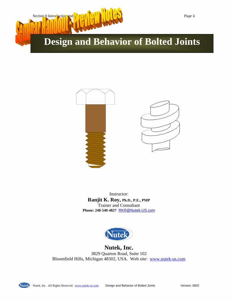
Instructor: Ranjit K. Roy, Ph.D., P.E., PMP
Trainer and Consultant Phone: 248-540-4827 [email protected]
Nutek, Inc. 3829 Quarton Road, Suite 102
Bloomfield Hills, Michigan 48302, USA. Web site: www.nutek-us.com
Design and Behavior of Bolted Joints
Section 0 Introduction and Content Page iii
Nutek, Inc. All Rights Reserved. www.nutek-us.com Design and Behavior of Bolted Joints Version: 0602
Design and Behavior of Bolted Joints Course Description:
Modern buildings, vehicles, machinery, and physical products of all sizes and shapes are put together by joining smaller components with another. A vast majority among these is assembled with fasteners, as they need to come apart for potential repair, replacement, or maintenance. Simply put, a fastener is a screw, nut, bolt or stud with external or internal threads. Although, there are numerous types of fasteners used in commerce, understanding the design and behavior of a threaded joint serves to comprehend the basic principles applicable to all fasteners.
Why should you study fasteners? Approximately 200 billion fasteners are utilized by the industry each year. Many such fasteners play important roles in transportation, safety and comfort of our modern life. A typical automobile, for example, uses about 4000 nuts and bolts. Because a few of them once in a while would come loose, over half of the warranty dollars for the same automobile can be related to fasteners.
In spite of its immense importance, bolted joints are not well understood. Part of the theoretical and empirical relations work fairly well in the design phase. Unfortunately, in installations, that is, in the assembly process, the behavior of a bolted joint depends on a large number of variables that are difficult or impossible to predict and control. Obtaining the desired load and configuration is subjected to a high degree of uncertainty that calls for a greater need for understanding of the operating principles involved. Thus the specialists who design and assemble things which must not fail; airplanes, nuclear reactor, engine connecting rods, engine block heads, all kinds of safety related items in an automobile, etc., must learn all there is to known about the behavior of the joints concerned.
This short session is intended for practicing design and manufacturing professionals who are involved in assembly of electro-mechanical hardware components of any size and shapes with fasteners of all kinds. Attendees are expected to participate in hands-on group exercises and solve a number of problems on theoretical principles discussed in the class (Attendees are required to bring a scientific calculator). Learning Objectives (bullet form): Upon completion of this seminar, you will learn how to: - Calculate forces in the fasteners - Establish what torque to specify - How to increase functional life of a joint - Analyze joints and its failure mechanism - Achieve better control of bolt tension and applied torque in the assembly operations - Utilize torque application machines more effectively - Reduce fastener related warranty and rework costs
Section 0 Introduction and Content Page iv
Nutek, Inc. All Rights Reserved. www.nutek-us.com Design and Behavior of Bolted Joints Version: 0602
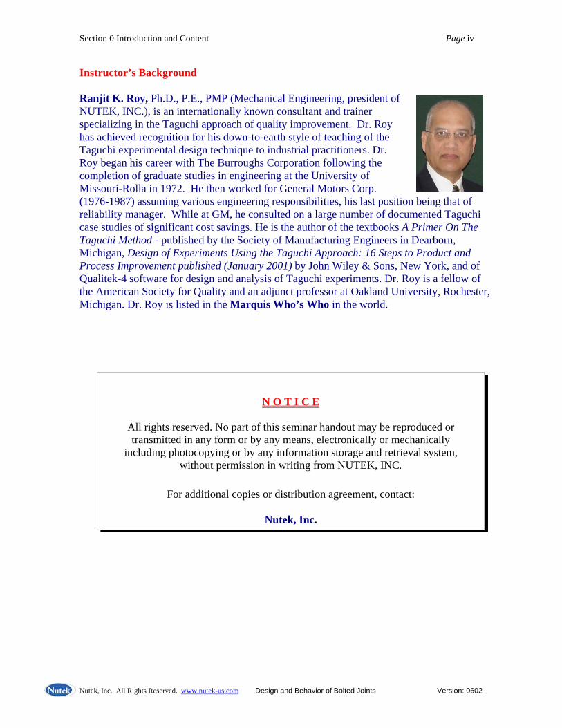
Instructor’s Background Ranjit K. Roy, Ph.D., P.E., PMP (Mechanical Engineering, president of NUTEK, INC.), is an internationally known consultant and trainer specializing in the Taguchi approach of quality improvement. Dr. Roy has achieved recognition for his down-to-earth style of teaching of the Taguchi experimental design technique to industrial practitioners. Dr. Roy began his career with The Burroughs Corporation following the completion of graduate studies in engineering at the University of Missouri-Rolla in 1972. He then worked for General Motors Corp. (1976-1987) assuming various engineering responsibilities, his last position being that of reliability manager. While at GM, he consulted on a large number of documented Taguchi case studies of significant cost savings. He is the author of the textbooks A Primer On The Taguchi Method - published by the Society of Manufacturing Engineers in Dearborn, Michigan, Design of Experiments Using the Taguchi Approach: 16 Steps to Product and Process Improvement published (January 2001) by John Wiley & Sons, New York, and of Qualitek-4 software for design and analysis of Taguchi experiments. Dr. Roy is a fellow of the American Society for Quality and an adjunct professor at Oakland University, Rochester, Michigan. Dr. Roy is listed in the Marquis Who’s Who in the world.
N O T I C E
All rights reserved. No part of this seminar handout may be reproduced or
transmitted in any form or by any means, electronically or mechanically including photocopying or by any information storage and retrieval system,
without permission in writing from NUTEK, INC.
For additional copies or distribution agreement, contact:
Nutek, Inc.

Section 0 Introduction and Content Page v
Nutek, Inc. All Rights Reserved. www.nutek-us.com Design and Behavior of Bolted Joints Version: 0602
ABOUT THE COURSE Course Content Section - A Fundamental Principles and Supporting Theories
• Why Study Fasteners? • Basic Principles of BOLT Operation • English vs. Metric Units of Measurements • Physics of Stationery Bodies • Rigid Body in a State of Equilibrium • Bolt Load and Free Body Diagram (FBD) • Effect of Friction • Friction Forces on Inclined Plane • Principles of Conservation of Energy • General Stiffness Principles • Stress, Strain and Mechanical Properties • Properties of Engineering Materials • Equivalent Joint Stiffness • Effect Of Joint Relaxation On Preload • How To Minimize Relaxation • Thermal Effect On Bolt Tension • Joint Behavior And Geometry Under External Load
Section B Fasteners Design Strategies and Assembly Considerations
• Torque and Tension Relationship • The Short-Form of Torque vs. Tension Relation • Uncertainty in Assembly Caused By Variability in Nut factor (K) • Factors That Affect Tension Variability • Assembly Torque and Tension Behavior • Process Variation and Process Capabilities • Primary Influencing Factors Affecting Preload • Bolt Tightening Strategies • Three Strategies Commonly Used to Control Preload • Inspection of Installed Torque • Bolt And Thread Geometry • Bolt Identification • Torque, Angle, and Tension Measuring Devices • Torque Scatter Due To Tool • Standardized Torque and Tension Values
Section 0 Introduction and Content Page vi
Nutek, Inc. All Rights Reserved. www.nutek-us.com Design and Behavior of Bolted Joints Version: 0602
• Bolted Joint Design Strategy • Joint Assembly and Behavior • Generalized Hooke’s Law • Mechanical Properties of Steel
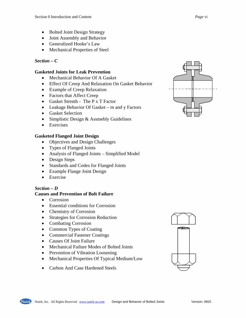
Section – C Gasketed Joints for Leak Prevention
• Mechanical Behavior Of A Gasket • Effect Of Creep And Relaxation On Gasket Behavior • Example of Creep Relaxation • Factors that Affect Creep • Gasket Strenth - The P x T Factor • Leakage Behavior Of Gasket – m and y Factors • Gasket Selection • Simplistic Design & Assmebly Guidelines • Exercises
Gasketed Flanged Joint Design
• Objectives and Design Challenges • Types of Flanged Joints • Analysis of Flanged Joints – Simplified Model • Design Steps • Standards and Codes for Flanged Joints • Example Flange Joint Design • Exercise
Section – D Causes and Prevention of Bolt Failure
• Corrosion • Essential conditions for Corrosion • Chemistry of Corrosion • Strategies for Corrosion Reduction • Combating Corrosion • Common Types of Coating • Commercial Fastener Coatings • Causes Of Joint Failure • Mechanical Failure Modes of Bolted Joints • Prevention of Vibration Loosening • Mechanical Properties Of Typical Medium/Low
• Carbon And Case Hardened Steels

Section 0 Introduction and Content Page vii
Nutek, Inc. All Rights Reserved. www.nutek-us.com Design and Behavior of Bolted Joints Version: 0602
• Numbering Systems for Carbon and Alloy Steels • Load Magnification on Joints • Fatigue Failure • Reducing Fatigue Problems
Appendix
• Sources of Bolting Specifications • The Fastener Quality Act: Insignia Recordals • Glossary of Fastener and Bolted Joint Terms • References
Continued ……………..
Design and Behavior of Bolted Joints
byRanjit K. Roy, Ph.D., P.E., PMP
Nutek, Inc.3829 Quarton Road, Suite 102
Bloomfield Hills, Michigan 48302, USA.Web Site: http://Nutek-us.com , E-mail: [email protected] 0807
Design and Behavior of Bolted JointsDesign and Behavior of Bolted Joints
W l !Welcome!
Participants from ????p
Slide 2Slide 2 R. Roy/Nutek, Inc. All Rights Reserved, Design and Behavior of Bolted Joints http://Nutek-us.com
Class Starts at: 8:00 AM Instructor: Ranjit Roy
Seminar Logistics
Start Time
Ref. Page N/A
End TimeBreaks (15 min after 55 -70 minutes of class)Lunch Time (55 minutes)( )Second day of the seminar – ScheduleFacilitiesActivities: Examples/solutions and group exercises c v es: a p es/so u o s a d g oup e e c sesthat require calculations (need a scientific calculator)Slides to Handout (Reference and textbook) Distractions: Please turn off cell phones and pagersp p g
Slide 3Slide 3 R. Roy/Nutek, Inc. All Rights Reserved, Design and Behavior of Bolted Joints http://Nutek-us.com
Introduction
Instructor:
Ref. Page N/A
Instructor:Mechanical engineerWorking in industry since 1973.I d d t lt t i 1987Independent consultant since 1987Specializes in product and process design improvement techniquePublished books and developed technical softwareAdjunct professor (Oakland University, Rochester, MI since 1976)
Slide 4Slide 4 R. Roy/Nutek, Inc. All Rights Reserved, Design and Behavior of Bolted Joints http://Nutek-us.com
Participant Introduction
Participants: (please tell the class)• Who you are• Your reasons for attending this session• How you would make use of information fromHow you would make use of information from this seminar• What do you WISH to do most when you have some free timesome free time
Slide 5Slide 5 R. Roy/Nutek, Inc. All Rights Reserved, Design and Behavior of Bolted Joints http://Nutek-us.com
Training Reference Materials
Handout - Content of most slides shown in this part of the presentation may be found in the seminar handout.p y
Slide 6Slide 6 R. Roy/Nutek, Inc. All Rights Reserved, Design and Behavior of Bolted Joints http://Nutek-us.com
Design and Behavior of Bolted JointsDesign and Behavior of Bolted Joints
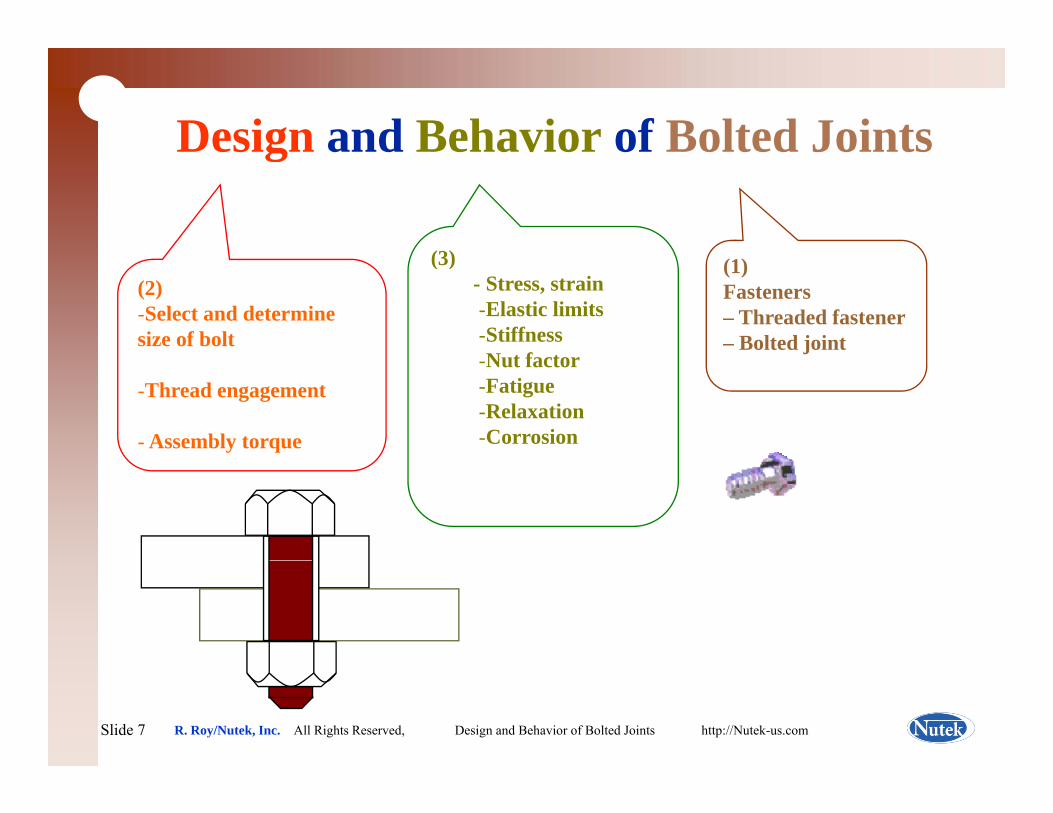
(3)(2)-Select and determine size of bolt
(1)Fasteners – Threaded fastener– Bolted joint
(3)- Stress, strain-Elastic limits-StiffnessN t f t
-Thread engagement
- Assembly torque
-Nut factor-Fatigue-Relaxation-Corrosion
Slide 7Slide 7 R. Roy/Nutek, Inc. All Rights Reserved, Design and Behavior of Bolted Joints http://Nutek-us.com
Expected Participant Benefits
Understand the engineering principles that control the behavior of threaded fasteners (Bolted Joints)
Ref. Page N/A
of threaded fasteners (Bolted Joints)Calculate design specifications from book values (Theoretical data)Cond ct appropriate st dies to generate joint dataConduct appropriate studies to generate joint dataSpecify assembly instructions
Torque requiredDesign Flanged Joints and specify required torqueUnderstand different modes of joint failure
Slide 8Slide 8 R. Roy/Nutek, Inc. All Rights Reserved, Design and Behavior of Bolted Joints http://Nutek-us.com
Why Study Fasteners
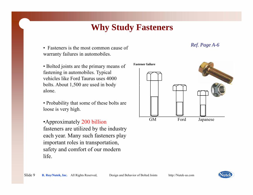
Ref. Page A-6• Fasteners is the most common cause of warranty failures in automobiles.
• Bolted joints are the primary means of fastening in automobiles. Typical vehicles like Ford Taurus uses 4000 bolts About 1 500 are used in body
Fastener failure
bolts. About 1,500 are used in body alone.
• Probability that some of these bolts are loose is very highloose is very high.
•Approximately 200 billionfasteners are utilized by the industry
h M h f t l
GM Ford Japanese
each year. Many such fasteners play important roles in transportation, safety and comfort of our modern life.
Slide 9Slide 9 R. Roy/Nutek, Inc. All Rights Reserved, Design and Behavior of Bolted Joints http://Nutek-us.com
Why Bolted Joints?
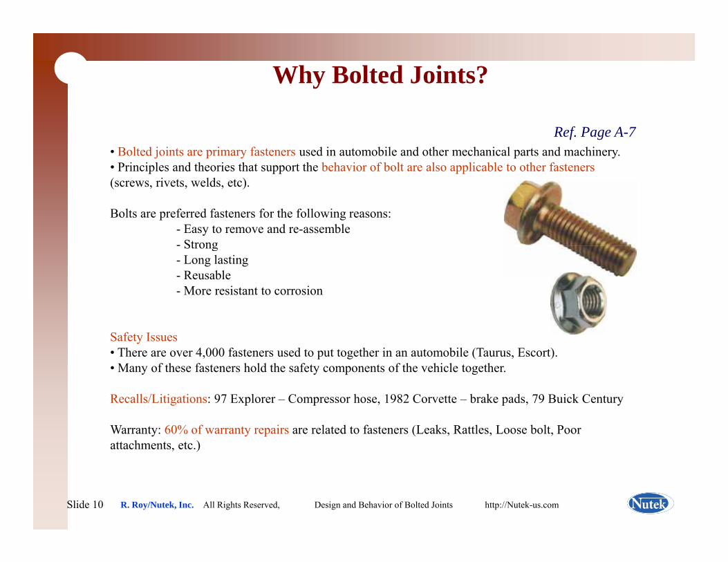
Ref. Page A-7• Bolted joints are primary fasteners used in automobile and other mechanical parts and machinery. • Principles and theories that support the behavior of bolt are also applicable to other fasteners(screws, rivets, welds, etc).
Bolts are preferred fasteners for the following reasons:- Easy to remove and re-assemble- Strong- Strong- Long lasting- Reusable- More resistant to corrosion
Safety Issues• There are over 4,000 fasteners used to put together in an automobile (Taurus, Escort).• Many of these fasteners hold the safety components of the vehicle together.
Recalls/Litigations: 97 Explorer – Compressor hose, 1982 Corvette – brake pads, 79 Buick Century
Warranty: 60% of warranty repairs are related to fasteners (Leaks, Rattles, Loose bolt, Poor attachments, etc.)
Slide 10Slide 10 R. Roy/Nutek, Inc. All Rights Reserved, Design and Behavior of Bolted Joints http://Nutek-us.com
Basic Principles of Bolt Operation
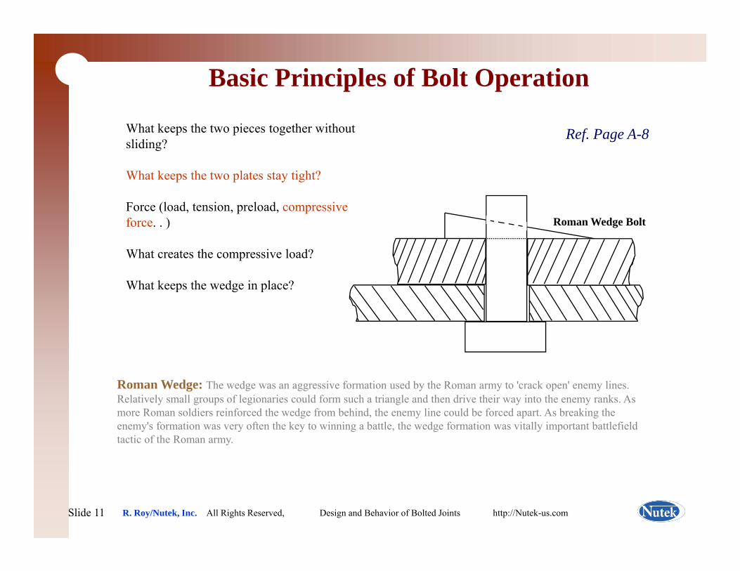
Ref. Page A-8What keeps the two pieces together without sliding?
What keeps the two plates stay tight?What keeps the two plates stay tight?
Force (load, tension, preload, compressive force. . )
Wh h i l d?
Roman Wedge Bolt
What creates the compressive load?
What keeps the wedge in place?
Roman Wedge: The wedge was an aggressive formation used by the Roman army to 'crack open' enemy lines. Relatively small groups of legionaries could form such a triangle and then drive their way into the enemy ranks. As more Roman soldiers reinforced the wedge from behind, the enemy line could be forced apart. As breaking the enemy's formation was very often the key to winning a battle, the wedge formation was vitally important battlefield tactic of the Roman army.
Slide 11Slide 11 R. Roy/Nutek, Inc. All Rights Reserved, Design and Behavior of Bolted Joints http://Nutek-us.com
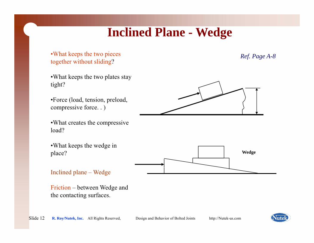
Inclined Plane - Wedge
Ref. Page A-8•What keeps the two pieces together without sliding?
Wh t k th t l t t•What keeps the two plates stay tight?
•Force (load, tension, preload, i f )compressive force. . )
•What creates the compressive load?
•What keeps the wedge in place? Wedge
Inclined plane – Wedge
Friction – between Wedge and the contacting surfaces.
Slide 12Slide 12 R. Roy/Nutek, Inc. All Rights Reserved, Design and Behavior of Bolted Joints http://Nutek-us.com
g

Screw – Spiraled Inclined Surface
Ref. Page A-9
Instead of the WEDGE, modern / h d SPIRAL/INCLINEDscrew/thread uses SPIRAL/INCLINED
surface to produce the load in the bolt.
A turn of the screw moves the screw oneA turn of the screw moves the screw one pitch distance.
Example: Screw Jack for automobilelifts the vehicle one pitch distance when Spiraled Inclined Surface –lifts the vehicle one pitch distance when turned one full revolution.
Securing assembly is the objective of any fastener. The key to securing
SCREW
a y as e e . e ey o secu gassembly that last for the life of the product is PROPER CLAMP LOAD. Clamp
T
Slide 13Slide 13 R. Roy/Nutek, Inc. All Rights Reserved, Design and Behavior of Bolted Joints http://Nutek-us.com
T
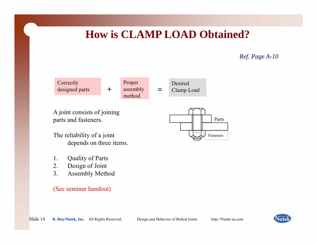
How is CLAMP LOAD Obtained?
Ref. Page A-10
Correctly designed parts +
Proper assembly method
=Desired Clamp Load
A joint consists of joining parts and fasteners.
The reliability of a joint
Parts
Fastenersy jdepends on three items.
1. Quality of Parts2. Design of Jointg3. Assembly Method
(See seminar handout)
Slide 14Slide 14 R. Roy/Nutek, Inc. All Rights Reserved, Design and Behavior of Bolted Joints http://Nutek-us.com
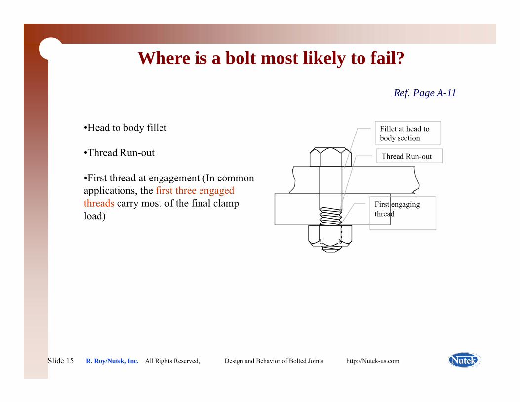
Where is a bolt most likely to fail?
Ref. Page A-11
H d t b d fill t•Head to body fillet
•Thread Run-out
Fi t th d t t (I
Fillet at head to body section
Thread Run-out
•First thread at engagement (In common applications, the first three engaged threads carry most of the final clamp load)
First engaging thread
Slide 15Slide 15 R. Roy/Nutek, Inc. All Rights Reserved, Design and Behavior of Bolted Joints http://Nutek-us.com
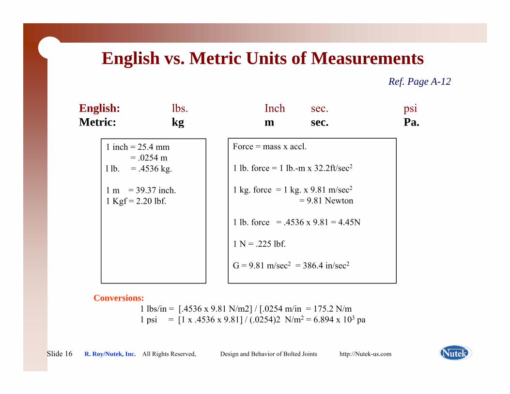
English vs. Metric Units of MeasurementsRef. Page A-12
English: lbs. Inch sec. psiMetric: kg m sec PaMetric: kg m sec. Pa.
1 inch = 25.4 mm= .0254 m
l lb. = .4536 kg.
Force = mass x accl.
1 lb. force = 1 lb.-m x 32.2ft/sec2g
1 m = 39.37 inch.1 Kgf = 2.20 lbf.
1 kg. force = 1 kg. x 9.81 m/sec2
= 9.81 Newton
1 lb force = 4536 x 9 81 = 4 45N1 lb. force = .4536 x 9.81 = 4.45N
1 N = .225 lbf.
G = 9.81 m/sec2 = 386.4 in/sec2
Conversions:1 lbs/in = [.4536 x 9.81 N/m2] / [.0254 m/in = 175.2 N/m1 psi = [1 x 4536 x 9 81] / ( 0254)2 N/m2 = 6 894 x 103 pa
Slide 16Slide 16 R. Roy/Nutek, Inc. All Rights Reserved, Design and Behavior of Bolted Joints http://Nutek-us.com
1 psi [1 x .4536 x 9.81] / (.0254)2 N/m 6.894 x 10 pa
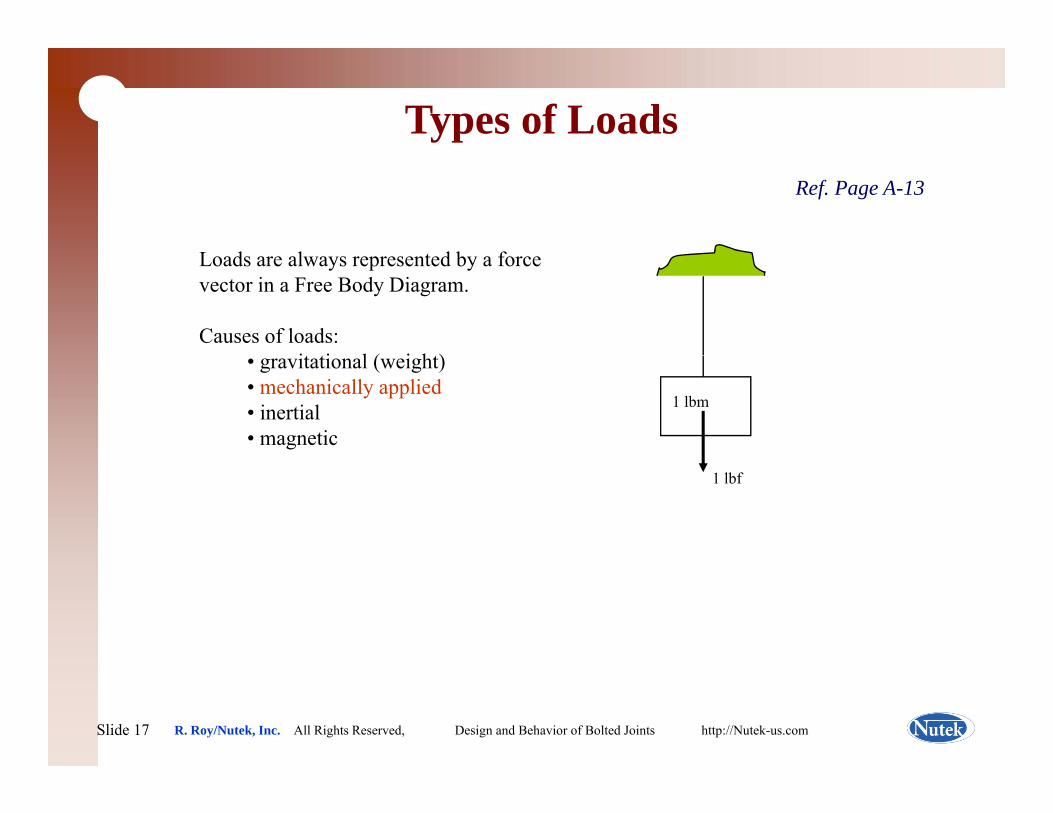
Types of LoadsRef. Page A-13
L d l d b fLoads are always represented by a force vector in a Free Body Diagram.
Causes of loads:i i l ( i h )• gravitational (weight)
• mechanically applied• inertial• magnetic
1 lbm
1 lbf
Slide 17Slide 17 R. Roy/Nutek, Inc. All Rights Reserved, Design and Behavior of Bolted Joints http://Nutek-us.com
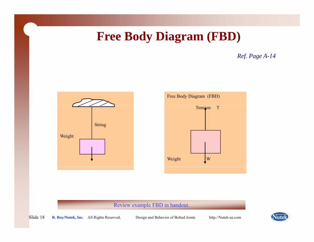
Free Body Diagram (FBD)Ref. Page A-14
Free Body Diagram (FBD)
i
String
Weight
Tension T
Weight
W
Weight W
Slide 18Slide 18 R. Roy/Nutek, Inc. All Rights Reserved, Design and Behavior of Bolted Joints http://Nutek-us.com
Review example FBD in handout.
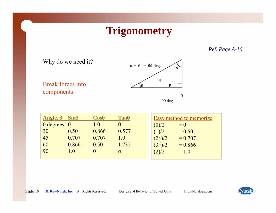
TrigonometryRef. Page A-16
Why do we need it?α + θ = 90 deg
Break forces into components.
α + θ 90 deg.
HP
α
θ
components.B
90 deg
Angle, θ Sinθ Cosθ Tanθ Easy method to memorizeg ,0 degrees 0 1.0 030 0.50 0.866 0.57745 0.707 0.707 1.060 0.866 0.50 1.732
y(0)/2 = 0(1)/2 = 0.50(2½)/2 = 0.707(3½)/2 = 0.866
90 1.0 0 α( )(2)/2 = 1.0
Slide 19Slide 19 R. Roy/Nutek, Inc. All Rights Reserved, Design and Behavior of Bolted Joints http://Nutek-us.com
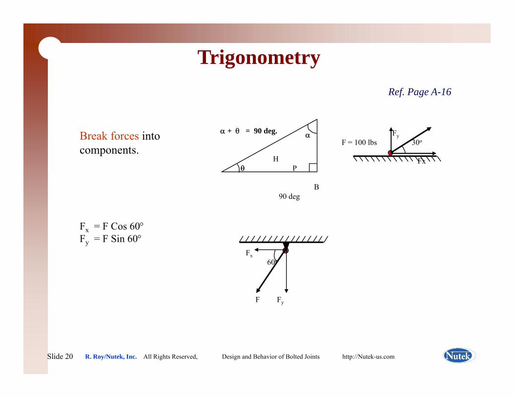
TrigonometryRef. Page A-16
Break forces into components.
α + θ = 90 deg.
HP
α
θ
FyF = 100 lbs 30o
Fx
F F C 60°
B90 deg
Fx = F Cos 60°Fy = F Sin 60°
Fx60o
F Fy
Slide 20Slide 20 R. Roy/Nutek, Inc. All Rights Reserved, Design and Behavior of Bolted Joints http://Nutek-us.com
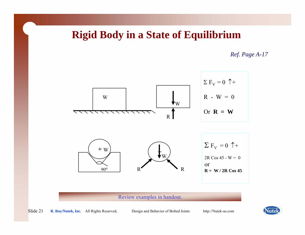
Rigid Body in a State of Equilibrium
Ref. Page A-17
WW
Σ FV = 0 ↑+
R - W = 0W
ROr R = W
WW
Σ FV = 0 ↑+
2R Cos 45 - W = 0
90o R Ror R = W / 2R Cos 45
Slide 21Slide 21 R. Roy/Nutek, Inc. All Rights Reserved, Design and Behavior of Bolted Joints http://Nutek-us.com
Review examples in handout.
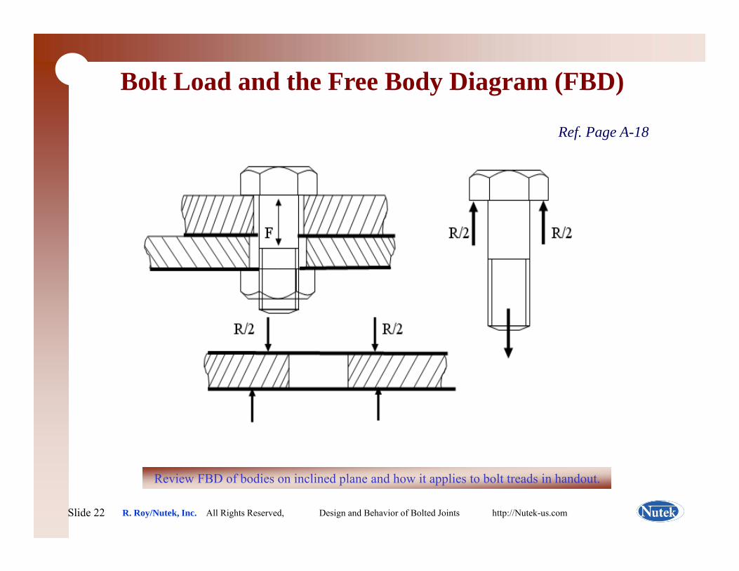
Bolt Load and the Free Body Diagram (FBD)
Ref. Page A-18
Slide 22Slide 22 R. Roy/Nutek, Inc. All Rights Reserved, Design and Behavior of Bolted Joints http://Nutek-us.com
Review FBD of bodies on inclined plane and how it applies to bolt treads in handout.
Time to Practice & LearnRef. Page N/A
Let’s do some calculation and see how the concepts discussed apply to real life
applicationspp
Most of the practice exercises are not in your handout. Please take notes and/or do it
yourself.
Slide 23Slide 23 R. Roy/Nutek, Inc. All Rights Reserved, Design and Behavior of Bolted Joints http://Nutek-us.com
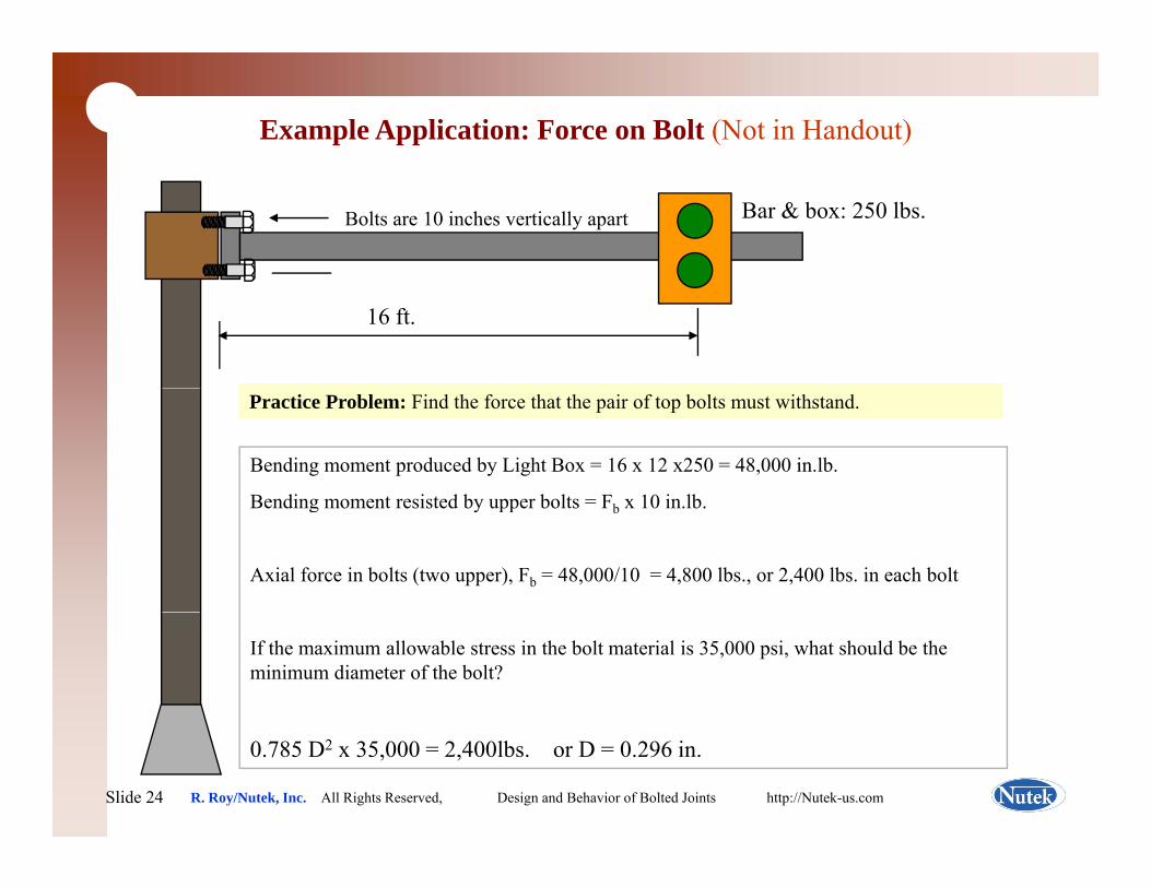
Example Application: Force on Bolt (Not in Handout)
Bolts are 10 inches vertically apart Bar & box: 250 lbs.
16 ft.
Bending moment produced by Light Box = 16 x 12 x250 = 48,000 in.lb.
Bending moment resisted by upper bolts = F x 10 in lb
Practice Problem: Find the force that the pair of top bolts must withstand.
Bending moment resisted by upper bolts = Fb x 10 in.lb.
Axial force in bolts (two upper), Fb = 48,000/10 = 4,800 lbs., or 2,400 lbs. in each bolt
If the maximum allowable stress in the bolt material is 35,000 psi, what should be the minimum diameter of the bolt?
Slide 24Slide 24 R. Roy/Nutek, Inc. All Rights Reserved, Design and Behavior of Bolted Joints http://Nutek-us.com
0.785 D2 x 35,000 = 2,400lbs. or D = 0.296 in.
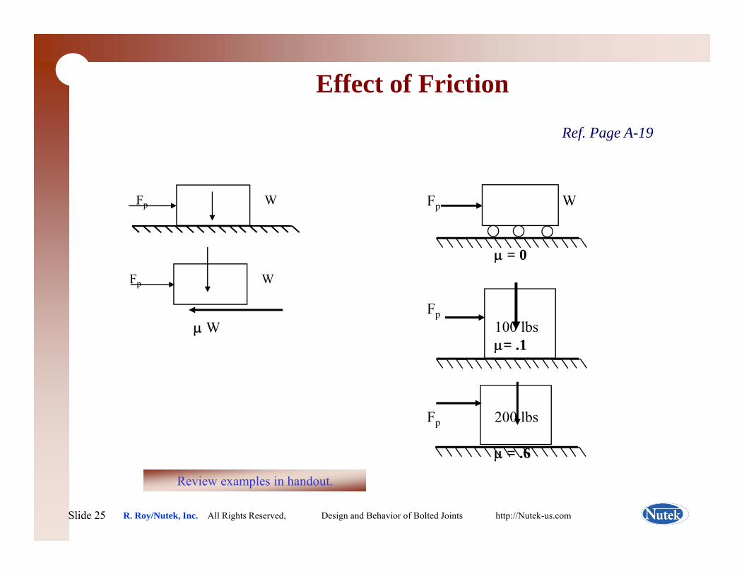
Effect of Friction
Ref. Page A-19
Fp W Fp W
0Fp W
W
μ = 0
Fp100 lbμ W 100 lbsμ= .1
Fp 200 lbs
μ = .6
Slide 25Slide 25 R. Roy/Nutek, Inc. All Rights Reserved, Design and Behavior of Bolted Joints http://Nutek-us.com
Review examples in handout.
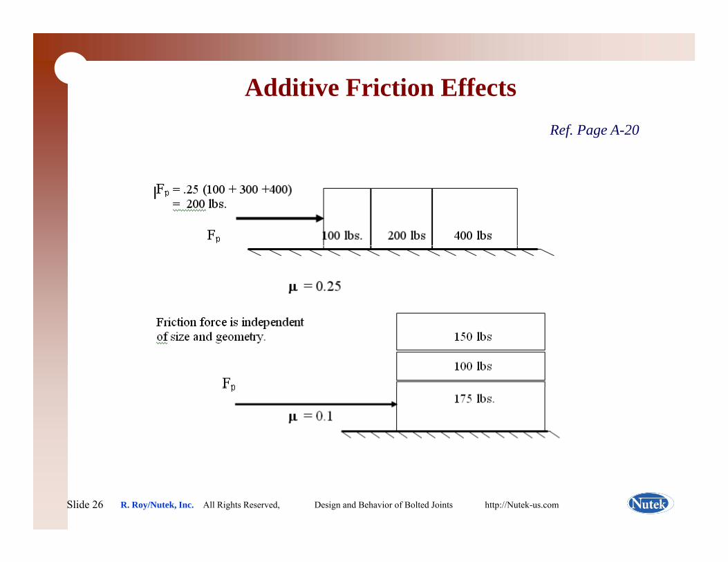
Additive Friction EffectsRef. Page A-20
Slide 26Slide 26 R. Roy/Nutek, Inc. All Rights Reserved, Design and Behavior of Bolted Joints http://Nutek-us.com
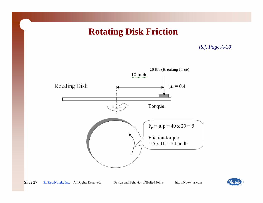
Rotating Disk Friction Ref. Page A-20
Slide 27Slide 27 R. Roy/Nutek, Inc. All Rights Reserved, Design and Behavior of Bolted Joints http://Nutek-us.com

Time to Practice & LearnRef. Page N/A
Let’s do some calculation and see how the concepts discussed apply to real life
applicationspp
Most of the practice exercises are not in your handout. Please take notes and/or do it
yourself.
Slide 28Slide 28 R. Roy/Nutek, Inc. All Rights Reserved, Design and Behavior of Bolted Joints http://Nutek-us.com
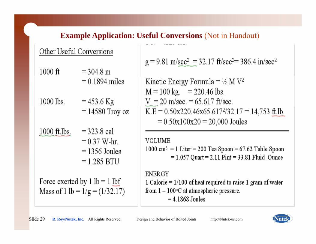
Example Application: Useful Conversions (Not in Handout)
Ref. Page B-xx
Slide 29Slide 29 R. Roy/Nutek, Inc. All Rights Reserved, Design and Behavior of Bolted Joints http://Nutek-us.com
Force on Bolts Fastening Brake PadsRef. Page B-N/A
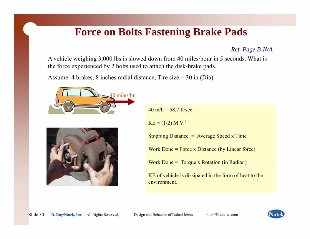
A vehicle weighing 3,000 lbs is slowed down from 40 miles/hour in 5 seconds. What is the force experienced by 2 bolts used to attach the disk-brake pads.
Assume: 4 brakes, 8 inches radial distance, Tire size = 30 in (Dia).
40 miles/hr
40 m/h = 58.7 ft/sec.
KE = (1/2) M V 2
St i Di t A S d TiStopping Distance = Average Speed x Time
Work Done = Force x Distance (by Linear force)
Work Done = Torque x Rotation (in Radian)q ( )
KE of vehicle is dissipated in the form of heat to the environment.
Slide 30Slide 30 R. Roy/Nutek, Inc. All Rights Reserved, Design and Behavior of Bolted Joints http://Nutek-us.com
Force on Bolts Fastening Brake Pads
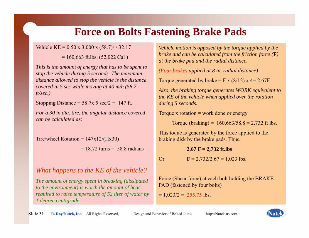
Ref. Page B-xxVehicle motion is opposed by the torque applied by the brake and can be calculated from the friction force (F) at the brake pad and the radial distance.
(Four brakes applied at 8 in. radial distance)
Vehicle KE = 0.50 x 3,000 x (58.7)2 / 32.17
= 160,663 ft.lbs. (52,022 Cal )
This is the amount of energy that has to be spent to stop the vehicle during 5 seconds The maximum
Torque generated by brake = F x (8/12) x 4= 2.67F
Also, the braking torque generates WORK equivalent to the KE of the vehicle when applied over the rotation during 5 seconds
stop the vehicle during 5 seconds. The maximum distance allowed to stop the vehicle is the distance covered in 5 sec while moving at 40 m/h (58.7 ft/sec.)
Stopping Distance = 58 7x 5 sec/2 = 147 ft during 5 seconds.
Torque x rotation = work done or energy
Torque (braking) = 160,663/58.8 = 2,732 ft lbs.
This toque is generated by the force applied to the
Stopping Distance 58.7x 5 sec/2 147 ft.
For a 30 in dia. tire, the angular distance covered can be calculated as:
This toque is generated by the force applied to the braking disk by the brake pads. Thus,
2.67 F = 2,732 ft.lbs
Or F = 2,732/2.67 = 1,023 lbs.
Tire/wheel Rotation = 147x12/(Πx30)
= 18.72 turns = 58.8 radians
Force (Shear force) at each bolt holding the BRAKE PAD (fastened by four bolts)
1 023/2 255 75 lbs
What happens to the KE of the vehicle?The amount of energy spent in breaking (dissipated to the environment) is worth the amount of heat required to raise temperature of 52 liter of water by
Slide 31Slide 31 R. Roy/Nutek, Inc. All Rights Reserved, Design and Behavior of Bolted Joints http://Nutek-us.com
= 1,023/2 = 255.75 lbs.required to raise temperature of 52 liter of water by 1 degree centigrade.
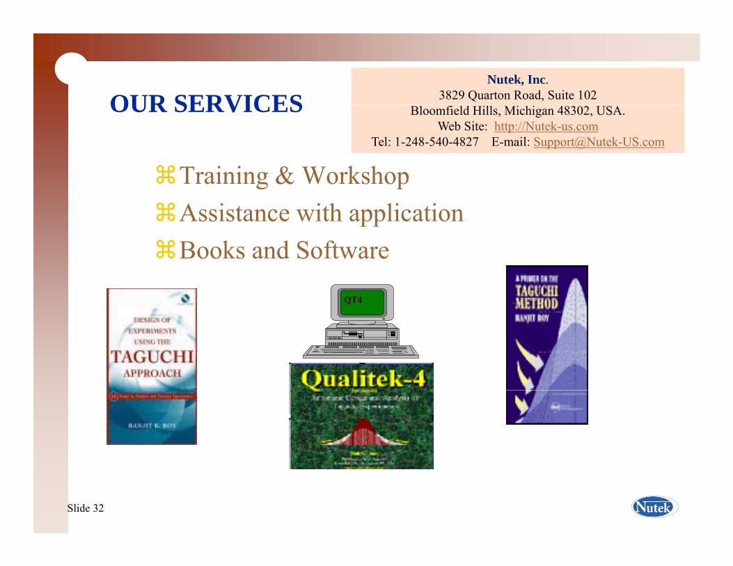
OUR SERVICESNutek, Inc.
3829 Quarton Road, Suite 102OUR SERVICES
Training & Workshop
Bloomfield Hills, Michigan 48302, USA.Web Site: http://Nutek-us.com
Tel: 1-248-540-4827 E-mail: [email protected]
Training & WorkshopAssistance with application Books and SoftwareBooks and Software
QT4
Slide 32Slide 32


![Logic Models Handout 1. Morehouse’s Logic Model [handout] Handout 2](https://img.pdfslide.us/doc/110x75/56649e685503460f94b6500c/logic-models-handout-1-morehouses-logic-model-handout-handout-2.jpg)