Embed Size (px)
Citation preview

This file is provided FREE OF CHARGE from the electromaniacs.com community You are free to distribute this file to other persons who needs it , but without of charge Also on http://electromaniacs.com you can find thousands of service manuals , schematics free of charge

PDP(Plasma Display Panel ) Display
LG Electronics DND Division
1. What is Plasma?2. What is Plasma Display Panel(PDP)?3. LG PDP Display(MNT & STB)4. SVC Precaution5. One Point SVC Guide

LG Electronics2TOP in Digital
1. What is Plasma?
Plasma can be accelerated and steered by electric and magnetic fields which allowsit to be controlled and applied. Plasma research is yielding a greater understanding ofthe universe.It also provides many practical uses: new manufacturing techniques, consumer products, and the prospect of abundant energy.
Ex.) Lightning, Aurora, Nebula, Flames, Neon Sign, Solar core Ex.) Lightning, Aurora, Nebula, Flames, Neon Sign, Solar core ……..
Plasma ?Plasma ?
Plasma is by far the most common form of matter.Plasma in the stars and in the tenuous space between them makes up over 99% of thevisible universe and perhaps most of that which is not visible.
Plasma consists of a collection of free-moving electrons and ions - atoms that have lostelectrons. Energy is needed to strip electrons from atoms to make plasma. The energy can be ofvarious origins:thermal, electrical, or light (ultraviolet light or intense visible light from a laser). With insufficient sustaining power, plasmas recombine into neutral gas.
Solid Solid ⇒⇒⇒⇒⇒⇒⇒⇒ Liquid Liquid ⇒⇒⇒⇒⇒⇒⇒⇒ Gas Gas ⇒⇒⇒⇒⇒⇒⇒⇒ Ion, Electron : The 4th State of Matter Ion, Electron : The 4th State of Matter

LG Electronics3TOP in Digital
Plasma Plasma --The 4th State of MatterThe 4th State of Matter
Plasma ?Plasma ?

LG Electronics4TOP in Digital
2. What is Plasma Display Panel(PDP)?
(1) How does it work?
(2) The Structure and mechanism of PDP
(3) Flow chart of a PDP fabrication
(4) Advantage of PDP Display
(5) Comparison of Display Devices
(6) Display Product Segments
(7) Usage of PDP Display

LG Electronics5TOP in Digital
2.What is Plasma Display Panel(PDP)? (1) How does it work?
Plasma display panel is the latest display technology and the best way to achieve flat panel displays with excellent image quality and large screen size that is easily viewable in any environment. PDP is an array of cells, known as pixels, which are composed of 3 sub-pixels, corresponding to the colors
Red, Green and Blue. Gas in a plasma state is used to react with phosphors in each sub-pixel to produce colored light (red, green or blue). These phosphors are the same types used in Cathode Ray Tube(CRT) devices such as televisions and standard computer monitors. You get the rich, dynamic colors that you expect. Each sub-pixel is individually controlled by advanced electronics to produce over 16 million different colors. All of this means that you get perfect images that are easily viewable in a display that is less than 6 inches thick.
Gas Discharge
YUV Generate
Visible Illuminate
Display
Scan(Y) ElectrodeSustain(Z) Electrode
(MgO)

LG Electronics6TOP in Digital
(2) The structure and mechanism of Panel
Protection(MgO) Dielectric
BUSElectrode
ITO Electrode
PlasmaPlasma
Visible Light
UV light
Address Electrode Glass
Barrier Rib
Bus ElectrodeITO Electrode
W/B
Barrier Rib
Electrode Fluorescent
< Upper Panel > < Lower Panel >
Fluorescent(R,G,B)
LG Electronics7TOP in Digital
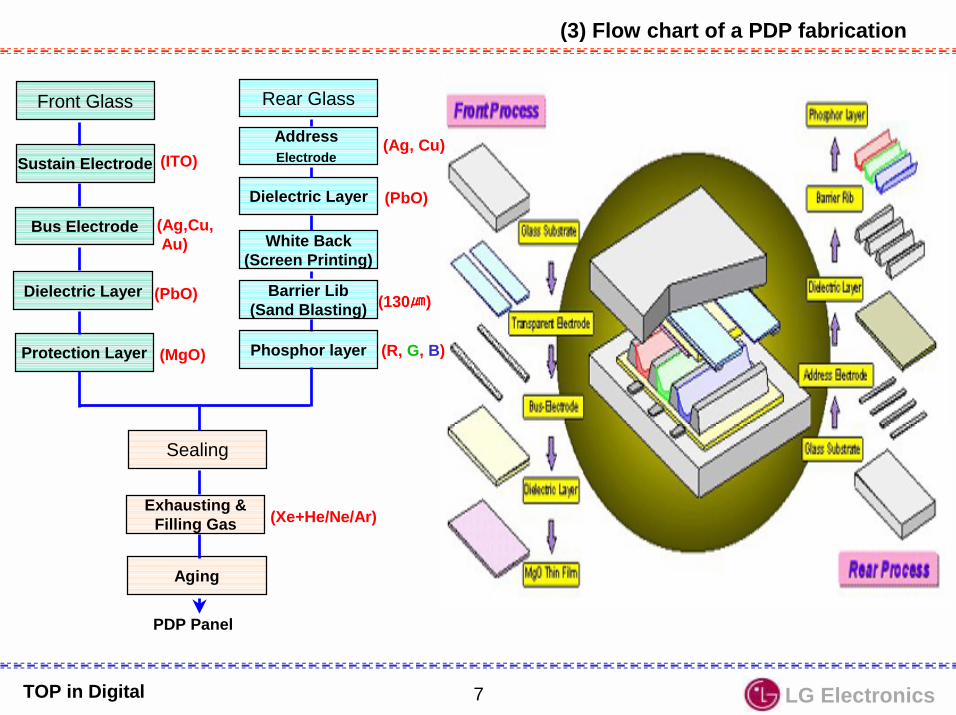
(3) Flow chart of a PDP fabrication
Front Glass
Sustain Electrode
Bus Electrode
Dielectric Layer
Protection Layer
Rear Glass
Address Electrode
Dielectric Layer
Barrier Lib(Sand Blasting)
Sealing
Exhausting &Filling Gas
Aging
(ITO)
(Ag,Cu,Au)
(PbO)
(Xe+He/Ne/Ar)
(Ag, Cu)
(PbO)
(R, G, B)(MgO)
(130)
Phosphor layer
White Back(Screen Printing)
PDP Panel

LG Electronics8TOP in Digital
(4) Advantages of PDP Display

LG Electronics9TOP in Digital
(5) Comparison of Display devices
Rear Projection

LG Electronics10TOP in Digital
(6) Display Market Segments
ELCRT
LCD
FED
PDP
Projection(Rear CRT/LCD)
PDA/Car Nav.Potable TV
NotebookPC
PC Monitor / TV PublicScreen
JumboScreen
10” 20” 30” 40” 50” 60” 70”
* FED : Field Emission Display** EL : Organic Electro Luminescent Diode
Projector

LG Electronics11TOP in Digital
(7) Usage of PDP Display
=> Home Theatre, A digital “poster” for the showroom, Visual guide or digital art display, Informationdisplay in reception areas, Business presentations, Easy-to-see monitor for fitness club
Home Theatre
Commercial Shop Public Display
Information Board Conference Room
Sports Center

LG Electronics12TOP in Digital
3. LG PDP Display(TV & MNT) (1) PDP Display System Structure(1)
MN-40PA10 & RN-BA10(Korea/USA)Interface between MP-40PA10 PDP Monitor and other AV machines
Set Top Box ( HD STB )
External Input(Right-Audio Left-Video
Component Audio
COMPONENT ( 480i /480P/720P/1080i )DVD / DTV INPUTY, PB, PR
RGB-PC input(VGA,SVGA)RGB-DTV(480P/720P/1080i)
CompositeVideo(Input output)
DVD ( 480i / 480P )
Audio InputRight - Left
RGB-PC/DTV

LG Electronics13TOP in Digital
RGB-PC input(VGA, SVGA)
Set Top Box ( HD STB )
Component 1 ( 480i input )
input1,2(R-voice, L-image)
RGB-DTV input(480P/720P/1080i)
Output(Right-Audio,Left-Video)
RGB INPUT/CONTROLAudio OUTPUT Right/Left25Pin D-Sub.
COMPONENT 2( 480P/720P
1080i )
DVD
VCR
PC
ANT INS Video input
DVD/DTV INPUT
RGB-PC/ DTV output
MN-40PA10 (PDP) connection MN-40PA10 ++++ RN-BA10(Analog STB)
LG Electronics14TOP in Digital
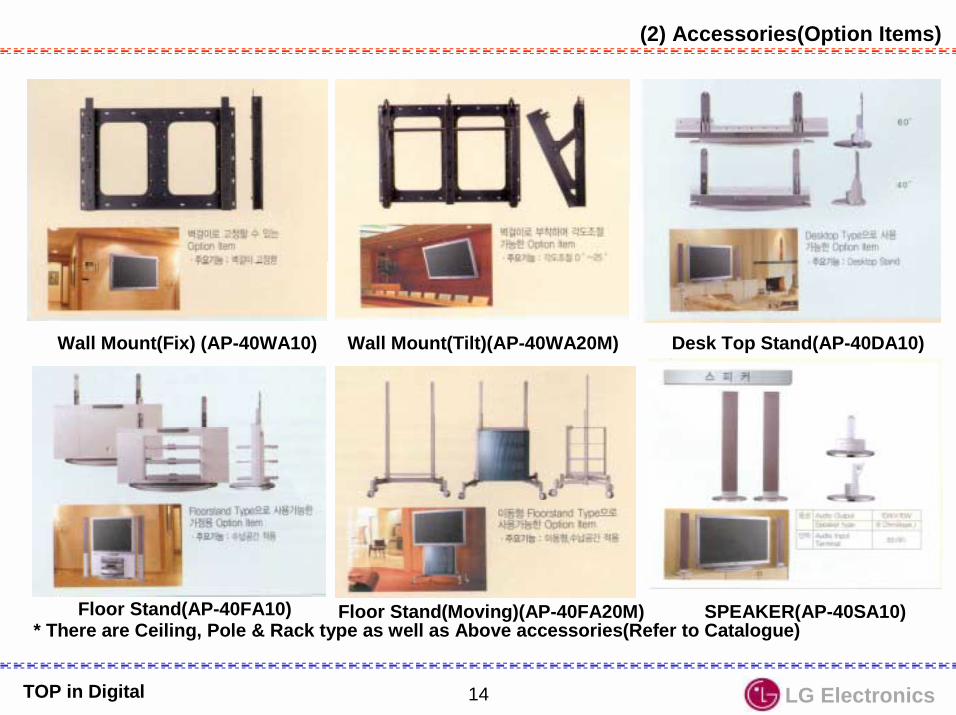
(2) Accessories(Option Items)
Wall Mount(Fix) (AP-40WA10) Wall Mount(Tilt)(AP-40WA20M) Desk Top Stand(AP-40DA10)
Floor Stand(Moving)(AP-40FA20M)Floor Stand(AP-40FA10) SPEAKER(AP-40SA10)* There are Ceiling, Pole & Rack type as well as Above accessories(Refer to Catalogue)

LG Electronics15TOP in Digital
Description Model Name
Desktop StandSpeaker
Speaker Stand
AP-40DA10
AP-40SA10
AP-40WA10
AP-40WA20M
AP-40CA10MN-40PA10
Description Model Name
AP-40FA10Floor Type
Stand RN-BA10
PLASMA Monitor
Wall MountingBracket
Tilt Wall Mounting
Bracket
Ceiling Mounting Bracket
PDP Tuner
AP-40SA10D
Floor TypeSpeaker Stand
AP-40SA10F

LG Electronics16TOP in Digital
Cord Length
RGB IN/Control 3000 mm
Terminal
External SPK 5000 mm
AC Input 2500 mm
(3) External Connection Terminals
(+) (-) (+) (-)
Ext. SPK(8Ω) Audio IN
PC In/DTV In 1(RGB/HV)
A Video
External Input
Y Cb/Pb Cr/Pr
DVD In/DTV In 2
AC InputR L R L RGB In/Control R L
A Video
External Input
Y Cb/Pb Cr/Pr
DVD In/DTV In2
R L PC In/DTV In 1(RGB/HV) Audio Input
R L RGB In/Control S Video(+) (-) (+) (-)
Ext. SPK(8Ω)
R L AC Input
1.40”/42”
2. 60”

LG Electronics17TOP in Digital
4-1)MP-40PA10(40” PDP)
1
2
3
4
5
6
7
8
9
10
- Fixing Points : Fix with M5 screws(3,4,5,6,7,8 ; 6 points)
- SPK Fixing Points : Fix with 3 tapping screws (1,2,9,10 (2 points each); 8 Points)
D/T,F/S Fixing Points
Wall Mount Fixing Points
(4) Fixing Points

LG Electronics18TOP in Digital
4-2)MN-60PZ10(60” PDP) - Fix with M8 Screw- Total 16 fixing points
( ; Wall Mount Holder orFLOOR STAND Fixing)
-1,3 4,6 : For SPK
1
2
3
4
5
6
7
8
10
9
11
12
13
15
14
16
D/T,F/S Fixing Points
Fixing Points
Pre-Fixing Point

LG Electronics19TOP in Digital
5-1)MONITOR PART
21
3
4
65
7
Cabinet
Filter
Line Filter
3790V00266B
NAMENO.
98
10
PCB ASSY, VSC
Supporter,Vertical
Back Cover Assy
4980V00164B/C
Supporter,Filter
1
2
4
3
5
8
6
9
Module Assy
Part Number3091V00288C
3809V00212C
10
Plate, Rear A/V 3301V00005A
(5) EXPLODE VIEW
3501V00028A6348Q-A002A
7
6871VMM602B
PCB ASSY, POWER 3501V00027E

LG Electronics20TOP in Digital
5-2)SET TOP BOX ASSY
1
345
NO. NAME Material
Panel,Control ABS
Panel, Front HIPS
1
2
Part Number
3720V00080B
3720V00079A
2
Case, Bottom SECC 1.0t
Case, Rear SECC 1.0t
Case, Top SECC 1.0t
3
4
5
3110V00101B
3110V00111C
3110V00102A

LG Electronics21TOP in Digital
VSC(VideoScanCon-verter)
PSU(PowerSupplyUnit)
5-3) PSU & VSC Board

LG Electronics22TOP in Digital
Local Key Board Local Key Board 7p P003A
7P
40P
4P
4P
P004A
PD501
P006A
P007A
6P
7P
12P
P002A
P005A
P003A 7P
12P P809
P815
6P
4P
P813
P810
8P
6P
P801
P814
4p 8p
6P
8P
P811
P807
6P P812
PDPControlBoard
6p 6p
4p 8p
12P
8P CON300
CON10240P
CON100
12P
8P CON102
CON101
CON302 CON301
CON3 CON2
6pCON304
6p CON303P801 P802
VSC
POWER
PDP MODULE(Upper X-Board)
POWER SW.B/D
P802 P803
2P CN8014PP007A
SPEAKER
2PEMI pack
(6) Inter-Connection Guide
PDP MODULE(Lower X-Board)
Y-Board(Scan)
Z-Board(Sustain)
TOP in Digital

LG Electronics23TOP in Digital
ADDRESS DRIVER(X)
ADDRESS DRIVER(X)
PANEL640XR,G,BX480
COMMONSUSTAINDRIVER(Z)
SCANSUSTAINDRIVER
(Y)VS(180V)
VA(80V)V set-up(275V)
Image Processing
Logic&
Scan-Controller(Control)
RGB(24bit)
VSYNC
HSYNC
BLANK
DISPEN
VS
+5vdrv
+15vdrv
VA
VA
Vsb
VSetup
VS
+5V
+15V
+5V
+15V
+5V
+15V
+5V
+15V
DATA( 41PIN )
PowerSupply
(AC-DC,DC-DC)
(7) Block Diagram
VideoScan
Converter&
Audio Amp.Ext. I/F(VSC)
EMI Filter AC Input
R/L
V/R/L
DVD
PC
(Spk.)
TD-620Set Top
Box
Control& RGB/HV,RL(25pin)
V/R/L
DVD
PC
ANT
PC/DTV
DTV
+5VST 5V+9V+32V
STBPower
AC Input
+5Vcntl
VSb(75V)
PDP Module

LG Electronics24TOP in Digital
MP--40PA10 VSC Board
Chip for flat panel display applicationVGA XGA(scale up/down)
Triple 8Bit, 80MSPS, 3.3V Video&Graphic Digitizerwith Digital PLL
Generates D-R/G/B(24bit) signal from Analog RGB
Display Processor & Scan Rate Converter(Format Converter)
Converts Interlace into Progressive15KHz 31KHz(2H, 1V)
Comb Filter & Video ProcessorSeparates CVBS signal into Y,U &V
P101V/R/L
P102DVD
DS102
DS101
IC203VPC3230Decoder
80Pin
IC203VPC3230Decoder
80Pin
3
Y,Cb,Cr
CVBS(A)
1IC204
SDA9410De-interlace
&D/A
100Pin
IC204SDA9410
De-interlace&
D/A100Pin
8 LU0-7
8 CHR0-7
IC303CXA2101AQVideo&Chroma
80Pin
IC303CXA2101AQVideo&Chroma
80Pin
STB-R/G/B/HS/VS(A)
5
PC-R/G/B/HS/VS (A)
5DTV-Y/Pb/Pr (A)
3 TV-Y/U/ V/HVs(A)
4
IC304THS8083
100Pin
IC304THS8083
100Pin
3 CXA-R/G/B(A )
IC401MX88L284
3X2M Scan converter
208Pin
IC401MX88L284
3X2M Scan converter
208Pin
IC001M37270
EEPROMµ-Com
IC001M37270
EEPROMµ-Com
IC4032M
SDRAM
IC4022M SDRAM
(R/G/B)(D)CAX-HS/VS 2
16D0-16
A0-10 D16-3111 16
OSD_R/G/B/YS
4 IC50174F541
IC50274F541
IC50374F541Buffer
IC50474F541
OSD_HS/VS2
HS/VS_OUT 2
8 DOR0-7
8 DOG0-7
8 DOB0-7
STB-POWERVSC DET/POWERHDSTB_DETSTB_SCL/SDAANA_STB_DET
7 PVS/PHS_OUT
2
PAR0-7
8
PAG0-7
8
PAB0-7
8
PD501(41Pin)
PDP Module
(D)
3X8
Multi-Component Processor(Baseband Video Signal Processor)
Outputs Analog R,G & B signal fromSTB,PC,DTV & TV signal
D-sub
25
D-sub
15
IC604LA7222
(Audio S/W)
(A)
P601L/R
STB/PC/DTV1
AV/DVD/DTV2IC602
CXA2022S(Tone Control)
IC602CXA2022S
(Tone Control)
IC603LA4282
Audio Amp.(12Wx2)
IC603LA4282
Audio Amp.(12Wx2)
Lout
Rout
P007A(SPK. Jack : 8Ω)10x10Wrms
I²C Bus
IC00224C08

LG Electronics25TOP in Digital
IC203VPC3230Decoder80 Pin
IC203VPC3230Decoder80 Pin
IC204SDA9410
De-interlace &D/A
100 Pin
IC204SDA9410
De-interlace &D/A
100 Pin
IC303CXA2101AQ
Video & Chroma80 Pin
IC303CXA2101AQ
Video & Chroma80 Pin
IC304THS8083100 Pin
IC304THS8083100 Pin
IC401MX88L284
3X2MScan Converter
208 Pin
IC401MX88L284
3X2MScan Converter
208 Pin
PD501(41Pin)PD501(41Pin)
CVBS
Y,Cb,Cr( 480 i ) LUM0-7
CHR0-7LLC1/2
TV-Y/U/V/HS/VS
Y/Pb/Pr( 480 p )
PC-R/G/B/HS/VS
3 CXA-R/G/B
3X8( R/G/B ) ( D )
PDP Module
Heat-Run pattern.Outputs Blue/Red/Green/White Patternwith 225 steps
VSC Board Block

LG Electronics26TOP in Digital
MICOM
EEPROMX2416P
VIDEO SWITCH
(M52758FP)
AUDIO
L
RAUDIO
AMPLA4282(L & R)
5
5
RGBHV
RGBHV 3
H/VSOG
COLOR DECODER
(VPC3230D) DEINTER-LACER
(FLI2200)
MEMORY(4M-BYTE)
Digital VideoEnhancer(FLI2220)
COLOR CONTROL&
VIDEO SWITCH
(CXA2101Q)
3Y,Pb,Pr(STB)
3Y,Pb,Pr(MNT)
A/D CONVERTER
(CXA3516R)SCALER
(JAG200)
MEMORY(6M-BYTE)
EPLD
(GEN. CLAMP)
TMDS TX
(SII150)
H
V
Clamp
2H/V
H
H
V
2PLLH/CLK
5
H/V/CLK/HBLK/VBLK
4
H/V/DE/CLK
DISP_EN
5
RGBHV
3RGB
3RGB
5Y,U,V,H,V
AUDIOSWITCH
(LA7222)
2H/V
MONOSTABLE MULTIBIB.(74LS123)
SOG_OUT CLAMP_AD
PORT EXP(M62320X4)
ROM(AT29C010)
(74HCT373)
YCbCr/YPbPr
CVBS
Y/C
2
YUV
21P8
4
H/V/FIELD/LLC1
42”/60” New VSC Board
Multi-Component Processor(Baseband Video Signal
Processor)bipolar IC which integratesbaseband signal processing, RGB signal processing and 4 video switching systems (including HV sync signalprocessing) using YCbCrinputs developed for multi-scan TV & configuring
high-end TV systems
Comb Filter Video Processorhigh quality video front -end, which
is targeted for 4:3 for 16:9, 50/60 & 100/120Hz TV sets, color decoder PAL/NTSC/SECAM PIP processing
Digital Component VideoDe-Interlacer/Line Doubler
8bit 135Mhz ADC(3),PLL(3), PIP,Gamma,
High order 3’rd generation Scaling

LG Electronics27TOP in Digital
A: Vsc(75V)TransB: Vsetup(275V) TransC: Va Inductor TransD: 5V Inductor TransE: Multi Inductor TransF: Multi(5V/15V/12V/30V/Va)TransG: St-By(5V/15V)TransH: Vs Inductor TransI : Vs(180V)TransJ: PFC Inductor Trans
<Adjustment Point>
VR802 : Va adjust(typ.70±±±±5V)VR804 : Vs adjust(typ.180±±±±5V)VR805 : Vsetup adjust(typ.275V)VR806 : Vsc adjust(typ.75V)
VsINDUCTOR
TRANS
VsTRANS
CEMENT
CEMENT
CEMENT
CEMENT
HEAT SIN
K
HEA
T SI
NK
Va Inductor 5V
Inductor
MultiInductor
MULTI-TRANS
TRANSPFC Inductor
HEAT SIN
K
ST-BYTRANS
HEAT SIN
K
HEAT SINK
HEAT SIN
K
CEMENT저항저항저항저항
VscTRANS
VsetupTRANS
A
B
D
G
F
E
H
I
J
C
HEAT SIN
K
AC In
1
2
3
4
VR803(Va)
VR802(5V Adj.)
VR801(32V Adj.)
VR804Vs
VR805Vset
VR806Vsc
CEMENT
VsDrive
MultiDrive
EMI(Line Filter) Pack EMIPowerSwitch
Power Supply Unit (40”)

LG Electronics28TOP in Digital
ST-BYSTR-G6100
5V
15V
PFCMC33262
380V 5V15V12V30V
ForwardTypeTL494
RCC TypeTL494
Va75V
Half-BridgeType
TL494Vs180V
RCC TypeTL494
VSC75VVsetup275V
Relay
AC Input90Vac~265Vac
Rectifier DIODE
Rectifier DIODE
POWER BLOCK
Best LG with Best TechnologyBest LG with Best TechnologyBest LG with Best TechnologyBest LG with Best Technology

LG Electronics29TOP in Digital
(8) Basic Structure of Optical Filter(Screen Filter)
Features of Optical Filter-. Reduce Electromagnetic Radiation and NIR(Near infrared light) emission.: EMI regulation(FCC A-class for Industry use, B-class for consumer use)
-.Transparency Control(40 ~ 70%), ex) FCC -A(sheet resistance = 2.5~3.5W) @ 60% , FCC -B(sheet resistance = 1.1~1.5W) @ 45%
-.Color Control : Color Temperature & Color Reproducibility control-.Reduce Surface Reflection-.Enhancement of Contrast-.Protection of PDP panel
Frame Printings(Screen Size)
Colored adhesive layer
Tempered Glass
Adhesive layer
AR(Antireflection) Film
Adhesive layer
PET Film with Multilayersputter-coatings
Multilayer sputter-coatingfor EMI shielding & NIR(Near Infrared Light)blocking
AR(Antireflection) Film
Electrode(Bus Bar)* EMI shielding : Mesh Fiber type & Film coating Type
Best LG with Best Technology

LG Electronics30TOP in Digital
Top View
Back Panel(Signal Input)
Inside
Best LG with Best TechnologyBest LG with Best TechnologyBest LG with Best TechnologyBest LG with Best Technology
RT-BA10(N-EU Multi) RZ-BA10(EU Multi)RN-BA10(NTSC) RP-BA10(Latin America)
(9) PDP Tuner(Set Top Box)
Interface Board
SMPS Board
Main Board

LG Electronics31TOP in Digital
12P 10P 7P
7P12P 10P
10P
8P
10P
8P
12P
12P
PX002 PX001 PX003STB Interface B/D
P403
P402 P401
STB - MAIN P002
P003
P810S
P870S
P001
PF01STB-CONTROL B/D
STB - POWER
PowerSwitch
Tuner
(10) RT-BA10( STB ) Inter-Connection
Best LG with Best TechnologyBest LG with Best TechnologyBest LG with Best TechnologyBest LG with Best Technology

LG Electronics32TOP in Digital
Single chip multi-standard Sound processors(Dolby Virtual)전체적인 TV음성신호처리
Mono/Stereo/Bilingual
A/V 1
SVHS
A/V 2
MNTOUT
DTV2in
IC 201CXA2069Q
64pin
IC 201CXA2069Q
64pin
3 (VRL)
2(Y/C)
3
3
MNT-L/R/V
TUNERTUNER
IC 601MSP3401
80pin
IC 601MSP3401
80pin
DCF(3D)(Digital Comb Filter)
DCF(3D)(Digital Comb Filter)TV Signal
(CVBS)
2TV-L/R
2AV-L/R
2
DCF-C/Y
1 DCF-VINIC 301
VPC323080pin
IC 301VPC3230
80pin
IC 701LGTV1001
64pin
IC 701LGTV1001
64pin
IC 302SDA9410
100pin
IC 302SDA9410
100pin
IC 001M37272u-COM
IC 001M37272u-COM
KEY-1
DVDin
3Y/U/V
IC 401CXA2101AQ
80pin
IC 401CXA2101AQ
80pin
IC 402BA7657
24pin
IC 402BA7657
24pin
P003P0033 OSD R/G/B/YS
3 SCL_A, SDA_B PC/DTV
1 S-MUTE
3
W/F-OUTOUT-LOUT-R
3KIN
KOUT 3
5SDA-HS/VS/U/V/Y
3SDA Y/V/U
2SDA-HS/VS
8CHROMA0-7
8LUMA0-7 8 C0-7
8Y0-7
2
SCL-ASDL-A
3CXA R/G/B
2CXA HS/VS
1
CXA-PC5
R/G/B/HS/VS
P401
P402
P403
PCR/G/BHS/VS
DTVR/G/BHS/VS
PCDTV
PC-R/L
ICX 001BA7657FICX 001BA7657F
DTV 1IN
PC INPCRGB/HV
PC/DTV-OUT
5 DTV-R/G/BHS/VS
3 PC-R/G/B
2PC-HS/VS IS 501
(25PinCable)
Input select switch for high definition display
Internal broadband RGB s/w
2
Y/C
3(DTV 2)Y/U/V
PDP M
OD
UA
L
Interface Board
TV Audio(SIF)
(VRL)
(Y,Cb,Cr)
(R,L)
IC 602/3/4SRS block
(option)
IC 602/3/4SRS block
(option)
7input/3outputwideband video Amp(20MHz, -3dB)
Y/C mix circuitA/V switch featuring I2C BUS
DTV2(R,L)
(Y,Pb,Pr)
SCL-ASDL-A2
CXA2069Q(pin 23/25)
R/LPC Audio(Stereo)
DTVRGB/HV
(R,L)
Comb filter video processorTV신호를 Digital Y/Cr/Cb化Multi-standard color decoder
A/D converter
8bit UVin 8bit UVout8bit Yin 8bit Yout
Improve the Image
Format converterInterlace scanning toProgressive scanning
SDA-U/V/Y
Multi-Component ProcessorAnalog R/G/B 출력
R/G/B化R/G/B Y/U/V
(Woofer Spk.Jack : 8Ω)15Wrms
(11) STB Block Diagram(1)
LG Electronics33TOP in Digital
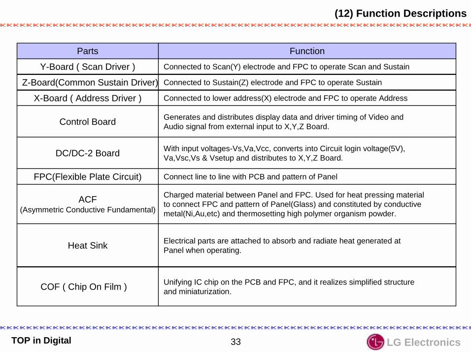
(12) Function Descriptions
Parts Function
Y-Board ( Scan Driver ) Connected to Scan(Y) electrode and FPC to operate Scan and Sustain
Z-Board(Common Sustain Driver) Connected to Sustain(Z) electrode and FPC to operate Sustain
X-Board ( Address Driver ) Connected to lower address(X) electrode and FPC to operate Address
Control Board Generates and distributes display data and driver timing of Video andAudio signal from external input to X,Y,Z Board.
DC/DC-2 Board With input voltages-Vs,Va,Vcc, converts into Circuit login voltage(5V),Va,Vsc,Vs & Vsetup and distributes to X,Y,Z Board.
FPC(Flexible Plate Circuit) Connect line to line with PCB and pattern of Panel
ACF(Asymmetric Conductive Fundamental)
Charged material between Panel and FPC. Used for heat pressing materialto connect FPC and pattern of Panel(Glass) and constituted by conductivemetal(Ni,Au,etc) and thermosetting high polymer organism powder.
Heat Sink Electrical parts are attached to absorb and radiate heat generated atPanel when operating.
COF ( Chip On Film ) Unifying IC chip on the PCB and FPC, and it realizes simplified structureand miniaturization.

LG Electronics34TOP in Digital
(13) Definition of Defect
A. Definition
Item Definition
Dark Dot Non lighting Cell Defect
Cause
Foreign material atCell or structural
defect
Flashing Cell Defect Toggles On/Off
Non-extinguishing Cell Defect Turn on always
High Intensity Cell Defect Brighter than other cell at same color or displayother color
Dark Dot
Bright Dot
Flashing Dot
High Intensity Dot
A zone
N ≤ 2 [cell/scn]Neighboring 2 Cells ≤ 1Neighboring over 3 Cells : 0
N ≤ 2 [cell/scn]Neighboring 2 Cells ≤ 1Neighboring over 3 Cells : 0
N ≤ 2 [cell/scn]Neighboring 2 Cells ≤ 1Neighboring over 3 Cells : 0
N ≤ 0 [cell/scn]
B zone
N ≤ 4 [cell/scn]Neighboring 2 Cells ≤ 1Neighboring over 3 Cells : 0
N ≤ 0 [cell/scn]
N ≤ 4 [cell/scn]Neighboring 2 Cells ≤ 1Neighboring over 3 Cells : 0
N ≤ 4 [cell/scn]Neighboring 2 Cells ≤ 1Neighboring over 3 Cells : 0
B. Specification

LG Electronics35TOP in Digital
Lift up the right and left of X-BOARD CONNECTOR.Lift up X-BOARD CONNECTOR and separate COP CONNECTOR by pulling up.
When you handle COF CONNECTOR, don’t pressure. First release LOCK and separate.If COF CONNECTOR is damaged, you should replace MODULE ASS’Y. So, be aware of this!!
1) X - Board COF Connector separation
When you exchange X-Board, first you should separate COF Connector. Be careful to handle it.COF Connector is attached to Module. When COF Connector is broken, Module ASS’Y must be replaced a new one.
When you exchange X-Board, first you should separate COF Connector. Be careful to handle it.COF Connector is attached to Module. When COF Connector is broken, Module ASS’Y must be replaced a new one.
WarningWarning
COF Connector
SVC Precaution

LG Electronics36TOP in Digital
Lift up each edge of left/right. Lifted condition
2) X - Board Connector separation
It’s easy to separate it by releasing Connector Lock .
Do not pressure or it can be hurt. When LOCK is hurt, replace a new X-BOARD
WarningWarning
Be careful to handle LOCK or it can be broken. When LOCK is broken, replace a new X-BOARD.

LG Electronics37TOP in Digital
Pull the white LOCK as shown in arrow
Pull the white LOCK as shown in arrow.
Separate COF CONNECTOR by pulling in the left.
3) Y - Board COF Connector separation
WarningWarning
Be careful to handle LOCK and COF Connector. When LOCK part is damaged, you should replacea new Y-Board. In case of COF Connector, Module Assembly.

LG Electronics38TOP in Digital
4) Z - Board COF Connector separation
Separate the fixed Screw of Z-Board.Pull out Lock as shown in arrow.
Condition in Lock part is pulled Pull COF Connector as shown in arrow.
It’s easy to separate COF on conditionthat Z-Board Screw is separated. In case Z-Board is assembled, it’s reallyhard to separate.
Be careful not to tear COF Connector.If COF Connector is torn, replace a new Module Assembly
WarningWarning COF Connector

LG Electronics39TOP in Digital
Push LOCK and pull out
PUSH PUSH PUSH
5) Connector separation Guide
PUSH PUSH PULL

LG Electronics40TOP in Digital
6) Control Board & VSC Board Connector

LG Electronics41TOP in Digital
Be sealed up after gas injection
Be careful to handle the sealed-up part after gas injection. If it is broken, the gas escapes. So, replace the Module.
7) Gas injection (Sealing up) condition
WarningWarning
Be sealed up after gas injection

LG Electronics42TOP in Digital
Power off in 2 ~ 3 minutes(Protection)
Power is On and off 2~3 minutes.(Protection)
Power is On and off 2~3 minutes.(Protection)
P301 Connector Open Check.P301 Connector Open Check. X - Board Top Right Change.X - Board Top Right Change.
P302 Connector Open CheckP302 Connector Open Check X - Board Top Left Change.X - Board Top Left Change.
P303 Connector Open CheckP303 Connector Open Check
P304 Connector Open CheckP304 Connector Open Check
P102 Connector Open CheckP102 Connector Open Check
X - Board Bottom Right Change.X - Board Bottom Right Change.
X - Board Bottom Left Change.X - Board Bottom Left Change.
Z - Board Change.Z - Board Change.
P3, P2 Connector Open CheckP3, P2 Connector Open Check Y - Board Change.Y - Board Change.
P005, P003 Connector Open CheckP005, P003 Connector Open Check
P006 Connector Open CheckP006 Connector Open Check
VSC- Board Change.VSC- Board Change.
VSC - Board Change.Sound Output IC Short Check
VSC - Board Change.Sound Output IC Short Check
Power Board ChangePower Board Change
OK
OK
OK
OK
OK
OK
OK
OKPROTECT operation;
When the load voltage is short.
When each voltage doesn’t work (in general)
PROTECT operation;
When the load voltage is short.
When each voltage doesn’t work (in general)
One Point SVC Guide

LG Electronics43TOP in Digital
L813 Cold Solder
Power off in 2 ~ 3 minutes(Protection)
CheckCheck
Open the Connector connecting to each Board to check the power is off.if each Board is same, check the Power Board and voltage.
Symptom : As soon as the power on,it’s off in 2 - 3minutes.(PROTECT operation)
Cause : No VS voltageL813 Coil cold soldering.

LG Electronics44TOP in Digital
MP-40PA10 uses 4 board such as left,right, top and bottom.Divide the screen in 4 and once you see ADD BAR check COF CONNECTORbetween MODULE and X-BOARD.If there is no defect in COF CONNECTOR replace X-BOARD.But the problem still remains and check the connector between X-BOARD andCONTROL BOARD. And if you can’t find defect, check CONTROL.
ADD BAR inspection and repair
HEATRUN : WHITE
Press the ADJ KEY and check the position of add bar by changing WHITE orRED or BLUE or GREEN
Top Right Top Left
Bottom Right Bottom Left
LG Electronics45TOP in Digital
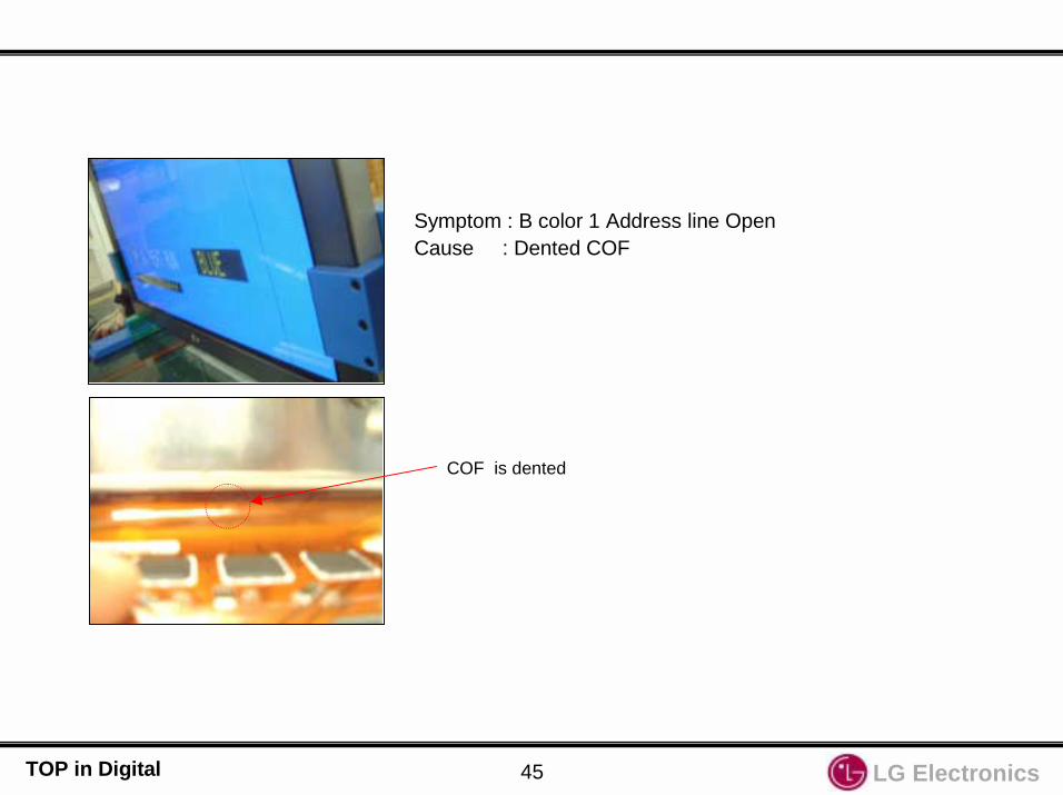
Symptom : B color 1 Address line OpenCause : Dented COF
COF is dented

LG Electronics46TOP in Digital
Symptom : Inferior R Address color Cause : Inferior DATA output by cold soldering 16 pin of IC14 in X-L-TOP
( Normal waveform after tearing off IC Pin)Countermeasure : Replace X-L-TOP board.
IC14
Cold Soldering
Abnormal waveform by cold soldering
Normal waveform after tearing off IC pin

LG Electronics47TOP in Digital
CheckCheck
The blue spreads on the screen (Mis-discharge) and power off in 2 ~ 3 seconds.If you turn on again, it will be same problem.
Symptom Causes Countermeasure
If 15V line voltage reduces below 14V,Mis-discharge occurs and power off because of protection circuit.
Replace PSU(Power Supply Unit)and defective X-Board.
If when Power on, screen shows like above and turn off in 2 seconds, check if turning off or not by disconnectingall X & Y boards.
Defective X-Board

LG Electronics48TOP in Digital
CheckCheck
The top left part of screen is broken(Top Right X-BOARD)
Symptom Cause Countermeasure
No 5V supply to Top rightX-Board.
Connect 5V line
Check Top right X-BOARD 5V.(If 0V, it happens)
Check 5V line from SMPS to X-BOARD.

LG Electronics49TOP in Digital
CheckCheck
Pinkish screen in the top left.(Top right X-BOARD)
Symptom Cause Countermeasure
No Va(70V) supply to Top right X-Board.
Connect 70V line
Check Top right X-BOARD Va(70V).(If 0V, it happens)
Check 70V(Va) line from SMPS to X-BOARD.

LG Electronics50TOP in Digital
CheckCheck
The 3/5 top left in the screen is blank(Top Right X-BOARD)
Symptom Cause Countermeasure
Check Top right X-BOARD 12V.( If 0V, it happens )
Check Top right X-BOARD Va(70V).(If 0V, it happens)
Check 12V & 70V(Va) line from SMPS to X-BOARD.
No 12V supply to Top rightX-Board.
No Va(70V) supply to Top right X-Board.
Connect 12V line
Connect 70V line

LG Electronics51TOP in Digital
CheckCheck
The 3/5 top right of the screen is blank.(Top left X-BOARD)
Symptom Cause Countermeasure
No 12V supply to Top leftX-Board.
No Va(70V) supply to Top left X-Board.
Connect 12V line
Connect 70V line
Check Top left X-BOARD 12V.( If 0V, it happens )
Check Top left X-BOARD Va(70V).(If 0V, it happens)
Check 12V & Va(70V) line from SMPS to X-BOARD.

LG Electronics52TOP in Digital
CheckCheck
Pinkish screen in the 1/5 top right(Top left X-BOARD)
P1 COF connector on Top leftX-Board is open.
Reassemble it
Check the contact point and Locking of P1 on Top left X-BOARD.
Symptom Cause Countermeasure

LG Electronics53TOP in Digital
CheckCheck
The 3/5 bottom left of screen is broken.(BOTTOM RIGHT X-BOARD)
Symptom Cause Countermeasure
No 5V supply to bottom rightX-Board.
Connect 5V line
Check Bottom right X-BOARD 5V.( If 0V, it happens )
Check 5V line from SMPS to X-BOARD.

LG Electronics54TOP in Digital
CheckCheck
The 3/5 bottom left of the screen is Blank.(Bottom Right X-BOARD)
Symptom Cause Countermeasure
Check Bottom right X-BOARD 12V.( If 0V, it happens )
Check 12V line from SMPS to X-BOARD.
No 12V supply to bottom rightX-Board.
No Va(70V) supply to bottom right X-Board.
Connect 12V line

LG Electronics55TOP in Digital
CheckCheck
The 2/5 right of the screen is broken.(Bottom left X-BOARD)
Symptom Cause Countermeasure
Check Bottom left X-BOARD 5V.( If 0V, it happens )
Check 5V line from SMPS to X-BOARD.
No 5V supply to bottom leftX-Board.
Connect 5V line

LG Electronics56TOP in Digital
CheckCheck
The 2/5 right part of the screen is blank.(Bottom left X-BOARD )
No 12V supply to bottom leftX-Board.
Connect 12V line
Check Bottom left X-BOARD 12V.( If 0V, it happens )
Check 12V line from SMPS to X-BOARD.
Symptom Cause Countermeasure

LG Electronics57TOP in Digital
CheckCheck
ADDRESS bar appears in the right bottom of the screen. (X-BOARD BOTTOM LEFT)
The connecting of X-Board bottomleft connector is bad.
Reassemble it.
Check connecting of the connector of bottom left X-BOARD.
Reassemble it.
X-BOARD BOTTOM LEFT CONNECTOROPEN.
Symptom Cause Countermeasure

LG Electronics58TOP in Digital
Examples

LG Electronics59TOP in Digital
CheckCheck
Screen is divided in top and bottom, and vertical barappears.
Connector(P13) is OPEN or Connecting condition is bad
Reassemble P13.
P13 CONNECTOR contact point inferior CHECK.
P13 CONNECTOR SIGNAL CHEK.
P13 CONNECTOR
Symptom Cause Countermeasure

LG Electronics60TOP in Digital
CheckCheck
Screen is broken and has the vertical/horizontal bar.
VSC Board Connector is Open. Reassemble VSC BoardConnector
Check the connector connectingReassemble the Connector
Symptom Cause Countermeasure

LG Electronics61TOP in Digital
CheckCheck
The screen is bluish(Mosaic screen)
Loose VSC Board Connector Reassemble VSC BOARDConnector
Check the connection condition of the Connector.
Reassemble the Connector.
Symptom Cause Countermeasure

LG Electronics62TOP in Digital
CheckCheck
The mosaic appears in the screen when it connects to VIDEO Input.(The sensibility of Y-signal is low.)When connected to Component Input, it is O.K.
Bad IC203 Replace IC203(VPC3230D)
Check if X201 on VSC board oscillates.Check Video In/Out of IC203 on VSC board.
IC201(VPC3230D)Decoder IC
Symptom Cause Countermeasure
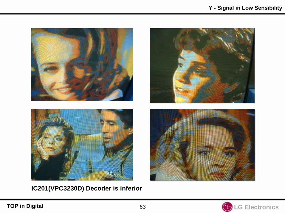
LG Electronics63TOP in Digital
Y - Signal in Low Sensibility
IC201(VPC3230D) Decoder is inferior

LG Electronics64TOP in Digital
CheckCheck
Noise with division of colors
Bad Connector connectingControl Board and VSC B/D.
Contact point and signal condition of Connector Control Board and VSC Board.
Abnormal Normal
Bad Connector
Symptom CauseCountermeasure
Change the Connector
LG ElectronicsTOP in Digital
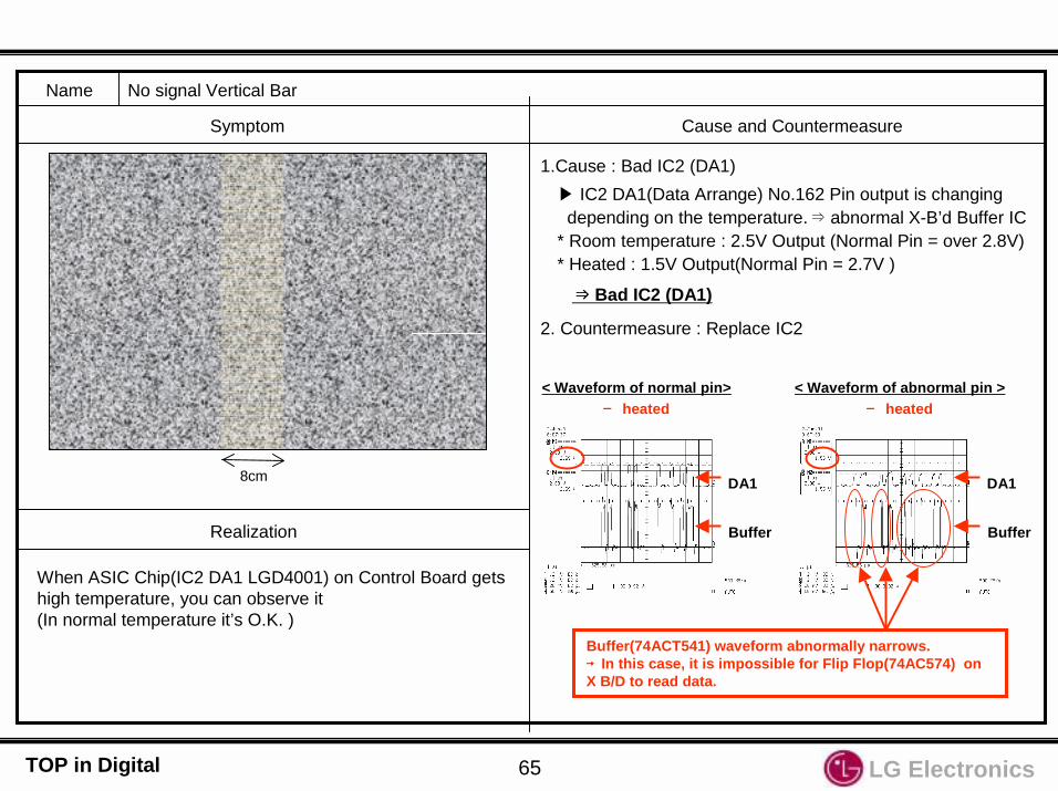
Name No signal Vertical Bar
Symptom Cause and Countermeasure
Realization
1.Cause : Bad IC2 (DA1)
8cm
When ASIC Chip(IC2 DA1 LGD4001) on Control Board getshigh temperature, you can observe it(In normal temperature it’s O.K. )
IC2 DA1(Data Arrange) No.162 Pin output is changing depending on the temperature.⇒ abnormal X-B’d Buffer IC
* Room temperature : 2.5V Output (Normal Pin = over 2.8V)* Heated : 1.5V Output(Normal Pin = 2.7V )
⇒⇒⇒⇒ Bad IC2 (DA1)
< Waveform of normal pin> heated
< Waveform of abnormal pin > heated
DA1
Buffer
DA1
Buffer
Buffer(74ACT541) waveform abnormally narrows. →→→→ In this case, it is impossible for Flip Flop(74AC574) on X B/D to read data.
2. Countermeasure : Replace IC2
65

LG ElectronicsTOP in Digital
Name Add Open (Green 1 Line)
Symptom Cause and Countermeasure
1.cause: Add. COF Drive IC inferior
Normal Line Data waveform Open Line Data output waveform
the output of inferior line less than that of the normal LineAdd. COF Drive IC inferior COF inspection검사기 : 24V Open check (normal 50V)
Add. COF Drive IC
COF불량시불량시불량시불량시부품변경부품변경부품변경부품변경가능한가가능한가가능한가가능한가?
66

LG ElectronicsTOP in Digital
Name Vertical bar when Power off/on(Mis-discharge)
Symptom Cause and Countermeasure
Realization
1.PDP Power on Mode external input (regardless of wire/wireless signal but it’s easy to reenact in wireless
signal)2. Remove Power Cord (Power’s off)3.after about 20minutes, insert Power cord (automatically the Power’s on and the vertical bar is shown as above)
1.Cause : Control board malfunctions when Power off/on.
2.Countermeasure: Change some parts on Control board.
3.Changing parts : A32_CTRL_03 B/D (Marked on PCB)-.R14,17,18,21 : 330 ==> 4.7K (Chip Resistor)-.R15,16,19,20 : 22K ==> 4.7K (Chip Resistor)-.C504, 505 : 0.1uF / 50V add (Chip Capacitor)
Control board
67


![Team Sales has a game plan to meet your needs. 500 000 ... SPARTANS SGT004 SGT009 COLUMBUS ... (additional charge]. Script font is additional charge](https://img.pdfslide.us/doc/110x75/5af330c97f8b9ad06191b8a9/team-sales-has-a-game-plan-to-meet-your-needs-500-000-spartans-sgt004-sgt009.jpg)


![This file is provided FREE OF CHARGE from the who needs it , but … · 2008. 10. 2. · the service menu [STATUS/TEST] block. If the abnormal status exceeds the allowable limit,](https://img.pdfslide.us/doc/110x75/6127b511da37a869995b7b4c/this-file-is-provided-free-of-charge-from-the-who-needs-it-but-2008-10-2.jpg)


