Embed Size (px)
Citation preview

This file is available for free download at http://www.iluvmyrx7.com
This file is fully text-searchable – select Edit and Find and type in what you’re looking for. This file is intended more for online viewing than printing out so some graphics may not print 100% legibly, you can zoom in on them if you need to.
www.iluvmyrx7.com

BRAKE SYSTEMArticle Text
1983 Mazda RX7For www.iluvmyrx7.com
Copyright © 1998 Mitchell Repair Information Company, LLCSunday, August 26, 2001 04:54PM
ARTICLE BEGINNING
1983 Brakes MAZDA
GLC Wagon, Pickups, RX7
DESCRIPTION
Brake system is hydraulically-operated, using a tandemmaster cylinder and power brake unit. Front brakes are floatingcaliper disc. Rear brakes on most models are leading/trailing drums. Floating caliper rear disc brakes are available on RX7 as anoption. Proportioning valves are used on most models to preventpremature lockup of rear wheels.
ADJUSTMENT
REAR DRUM BRAKE SHOES
GLC Wagon, RX7 & Pickups 1) Raise and support rear of vehicle. Release parking brake.Remove rear wheel. Through the hole in the brake drum of the GLCWagon or on the backing plate of all others, remove the star wheelplug. Insert a flat-tipped screwdriver, and move the star wheelforward until the wheel is locked. See Fig. 1.
Fig. 1: Adjusting Rear Brake Shoe-to-Drum Position
2) On all backing plates, remove the pawl lever hole plug.Insert a flat-tipped screwdriver through hole. Push on the pawl leverself-adjuster, so the star wheel may be moved in the reversedirection. 3) Back off the star wheel about 3 or 4 notches, so the
BRAKE SYSTEMArticle Text (p. 2)
1983 Mazda RX7For www.iluvmyrx7.com
Copyright © 1998 Mitchell Repair Information Company, LLCSunday, August 26, 2001 04:54PM
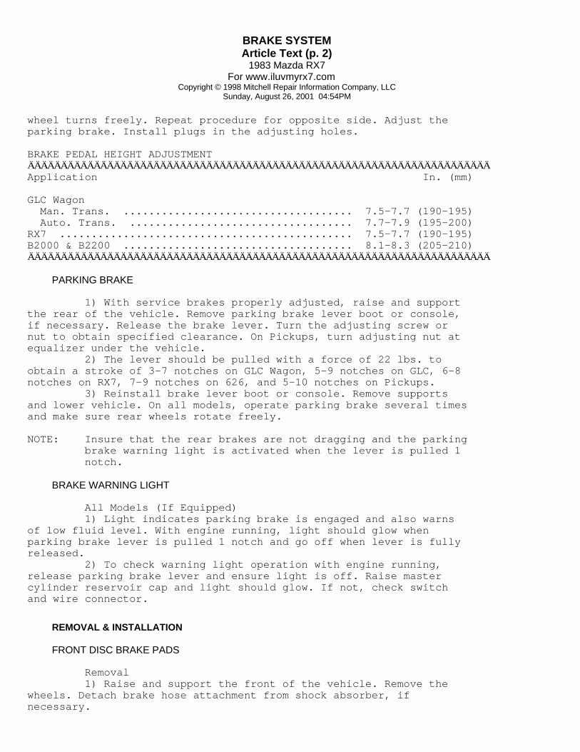
wheel turns freely. Repeat procedure for opposite side. Adjust theparking brake. Install plugs in the adjusting holes.
BRAKE PEDAL HEIGHT ADJUSTMENTÄÄÄÄÄÄÄÄÄÄÄÄÄÄÄÄÄÄÄÄÄÄÄÄÄÄÄÄÄÄÄÄÄÄÄÄÄÄÄÄÄÄÄÄÄÄÄÄÄÄÄÄÄÄÄÄÄÄÄÄÄÄÄÄÄÄÄÄÄÄApplication In. (mm)
GLC Wagon Man. Trans. .................................... 7.5-7.7 (190-195) Auto. Trans. ................................... 7.7-7.9 (195-200)RX7 .............................................. 7.5-7.7 (190-195)B2000 & B2200 .................................... 8.1-8.3 (205-210)ÄÄÄÄÄÄÄÄÄÄÄÄÄÄÄÄÄÄÄÄÄÄÄÄÄÄÄÄÄÄÄÄÄÄÄÄÄÄÄÄÄÄÄÄÄÄÄÄÄÄÄÄÄÄÄÄÄÄÄÄÄÄÄÄÄÄÄÄÄÄ
PARKING BRAKE
1) With service brakes properly adjusted, raise and supportthe rear of the vehicle. Remove parking brake lever boot or console,if necessary. Release the brake lever. Turn the adjusting screw ornut to obtain specified clearance. On Pickups, turn adjusting nut atequalizer under the vehicle. 2) The lever should be pulled with a force of 22 lbs. toobtain a stroke of 3-7 notches on GLC Wagon, 5-9 notches on GLC, 6-8notches on RX7, 7-9 notches on 626, and 5-10 notches on Pickups. 3) Reinstall brake lever boot or console. Remove supportsand lower vehicle. On all models, operate parking brake several timesand make sure rear wheels rotate freely.
NOTE: Insure that the rear brakes are not dragging and the parking brake warning light is activated when the lever is pulled 1 notch.
BRAKE WARNING LIGHT
All Models (If Equipped) 1) Light indicates parking brake is engaged and also warnsof low fluid level. With engine running, light should glow whenparking brake lever is pulled 1 notch and go off when lever is fullyreleased. 2) To check warning light operation with engine running,release parking brake lever and ensure light is off. Raise mastercylinder reservoir cap and light should glow. If not, check switchand wire connector.
REMOVAL & INSTALLATION
FRONT DISC BRAKE PADS
Removal 1) Raise and support the front of the vehicle. Remove thewheels. Detach brake hose attachment from shock absorber, ifnecessary.

BRAKE SYSTEMArticle Text (p. 3)
1983 Mazda RX7For www.iluvmyrx7.com
Copyright © 1998 Mitchell Repair Information Company, LLCSunday, August 26, 2001 04:54PM
2) On RX7 remove lower caliper guide pin andpivot caliper body up out of way. On GLC Wagon and Pickups removelocking clips and stopper plates. 3) Remove caliper body and hang from frame with wire. Do notdisconnect hydraulic lines. On all models, remove anti-rattle springs(clips), pads, and shims, if equipped.
Installation 1) To install, reverse removal procedure. Before mountingcaliper, loosen bleed screw, and seat piston. Tighten bleed screw. 2) After pad installation, depress brake pedal several timesto seat pads. Bleed hydraulic system, if required.
NOTE: Grease pad mounting support, caliper contact area, and shims with special grease (NLGI No. 2 or equivalent).
REAR DISC BRAKE PADS
Removal (RX7) 1) Raise and support the rear of the vehicle. Remove wheel.Disconnect parking brake cable from caliper. Remove lower caliperattaching bolt. 2) Lift the lower side of caliper. Remove anti-rattlespring. Remove disc brake pads and shims.
Installation 1) Using brake piston wrench (49 FA18 602), turn pistonclockwise until piston is inserted into caliper fully. 2) Position piston so that dowel on pad will seat in pistonstopper groove. To complete installation, reverse removal procedure.
FRONT DISC BRAKE CALIPER
Removal 1) Raise and support the front of the vehicle. Remove thewheel. Disconnect and plug the fluid line at caliper. On RX7, removelower caliper bolt, lift the caliper body, and remove by slidingtoward the inside of the vehicle. 2) On GLC Wagon and Pickups, remove locking clips, stopperplates, and anti-rattle spring. Lift off caliper. Remove disc pads aspreviously described.
Installation To install, reverse removal procedure and bleed hydraulicsystem.
REAR BRAKE CALIPER
Removal (RX7) 1) Raise and support the rear of the vehicle. Remove thewheel. Disconnect parking brake cable from caliper. 2) Remove caliper attaching bolt (lower side). Lift up
BRAKE SYSTEMArticle Text (p. 4)
1983 Mazda RX7For www.iluvmyrx7.com
Copyright © 1998 Mitchell Repair Information Company, LLCSunday, August 26, 2001 04:54PM
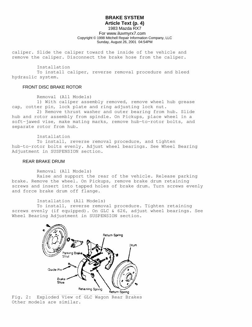
caliper. Slide the caliper toward the inside of the vehicle andremove the caliper. Disconnect the brake hose from the caliper.
Installation To install caliper, reverse removal procedure and bleedhydraulic system.
FRONT DISC BRAKE ROTOR
Removal (All Models) 1) With caliper assembly removed, remove wheel hub greasecap, cotter pin, lock plate and ring adjusting lock nut. 2) Remove thrust washer and outer bearing from hub. Slidehub and rotor assembly from spindle. On Pickups, place wheel in asoft-jawed vise, make mating marks, remove hub-to-rotor bolts, andseparate rotor from hub.
Installation To install, reverse removal procedure, and tightenhub-to-rotor bolts evenly. Adjust wheel bearings. See Wheel BearingAdjustment in SUSPENSION section.
REAR BRAKE DRUM
Removal (All Models) Raise and support the rear of the vehicle. Release parkingbrake. Remove the wheel. On Pickups, remove brake drum retainingscrews and insert into tapped holes of brake drum. Turn screws evenlyand force brake drum off flange.
Installation (All Models) To install, reverse removal procedure. Tighten retainingscrews evenly (if equipped). On GLC & 626, adjust wheel bearings. SeeWheel Bearing Adjustment in SUSPENSION section.
Fig. 2: Exploded View of GLC Wagon Rear BrakesOther models are similar.

BRAKE SYSTEMArticle Text (p. 5)
1983 Mazda RX7For www.iluvmyrx7.com
Copyright © 1998 Mitchell Repair Information Company, LLCSunday, August 26, 2001 04:54PM
REAR BRAKE SHOES
Removal (All Models) 1) With brake drum removed, remove brake shoe returnsprings, retaining springs and guide pins. Remove brake shoes. 2) Remove parking brake strut and disconnect parking brakecable from operating lever of secondary shoe.
Installation 1) Lubricate adjusting screw threads and contact surfaces ofshoes and backing plate with brake grease. Install parking brakeoperating lever to secondary shoe and secure with clip. Engageoperating lever with parking brake cable. 2) Position operating strut between slots of shoes. Mountassembly to backing plate so slots in shoes are toward adjustingscrews. Install return springs and retainer springs.
MASTER CYLINDER
Removal 1) Disconnect fluid level sensor coupler, if equipped.Disconnect and plug hydraulic lines at master cylinder to prevententry of dirt and loss of fluid. 2) Remove nuts attaching master cylinder to firewall orpower brake unit and remove master cylinder from vehicle. On RX7,remove proportioning valve by-pass bolt.
Installation To install, reverse removal procedure and bleed hydraulicsystem.
POWER BRAKE UNIT
Removal 1) Remove master cylinder from power brake unit beforeremoving power brake unit. Disconnect vacuum line at power brake unit. 2) From inside vehicle, remove cotter pin and clevis pinattaching push rod to brake pedal, and separate. 3) Remove nuts retaining power unit to firewall. Removepower brake unit and master cylinder as an assembly. Separate mastercylinder from power brake unit.
Installation To install, reverse removal procedure and bleed hydraulicsystem.
OVERHAUL
FRONT DISC BRAKE CALIPER
Disassembly 1) Thoroughly clean exterior of caliper and remove retainer
BRAKE SYSTEMArticle Text (p. 6)
1983 Mazda RX7For www.iluvmyrx7.com
Copyright © 1998 Mitchell Repair Information Company, LLCSunday, August 26, 2001 04:54PM
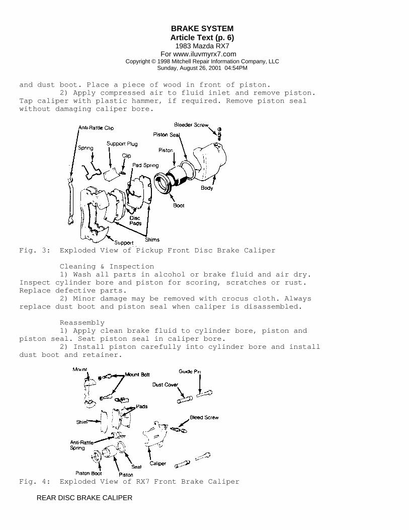
and dust boot. Place a piece of wood in front of piston. 2) Apply compressed air to fluid inlet and remove piston.Tap caliper with plastic hammer, if required. Remove piston sealwithout damaging caliper bore.
Fig. 3: Exploded View of Pickup Front Disc Brake Caliper
Cleaning & Inspection 1) Wash all parts in alcohol or brake fluid and air dry.Inspect cylinder bore and piston for scoring, scratches or rust.Replace defective parts. 2) Minor damage may be removed with crocus cloth. Alwaysreplace dust boot and piston seal when caliper is disassembled.
Reassembly 1) Apply clean brake fluid to cylinder bore, piston andpiston seal. Seat piston seal in caliper bore. 2) Install piston carefully into cylinder bore and installdust boot and retainer.
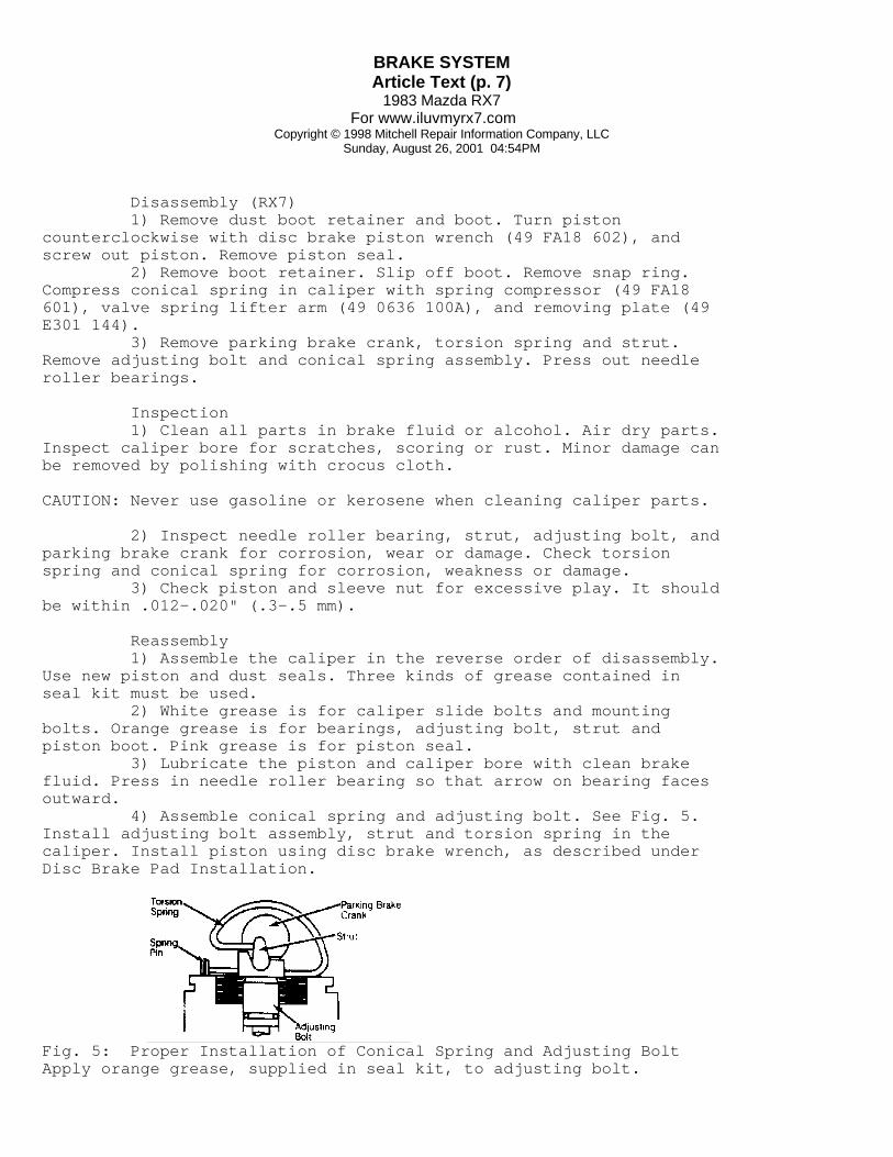
Fig. 4: Exploded View of RX7 Front Brake Caliper
REAR DISC BRAKE CALIPER
BRAKE SYSTEMArticle Text (p. 7)
1983 Mazda RX7For www.iluvmyrx7.com
Copyright © 1998 Mitchell Repair Information Company, LLCSunday, August 26, 2001 04:54PM
Disassembly (RX7) 1) Remove dust boot retainer and boot. Turn pistoncounterclockwise with disc brake piston wrench (49 FA18 602), andscrew out piston. Remove piston seal. 2) Remove boot retainer. Slip off boot. Remove snap ring.Compress conical spring in caliper with spring compressor (49 FA18601), valve spring lifter arm (49 0636 100A), and removing plate (49E301 144). 3) Remove parking brake crank, torsion spring and strut.Remove adjusting bolt and conical spring assembly. Press out needleroller bearings.
Inspection 1) Clean all parts in brake fluid or alcohol. Air dry parts.Inspect caliper bore for scratches, scoring or rust. Minor damage canbe removed by polishing with crocus cloth.
CAUTION: Never use gasoline or kerosene when cleaning caliper parts.
2) Inspect needle roller bearing, strut, adjusting bolt, andparking brake crank for corrosion, wear or damage. Check torsionspring and conical spring for corrosion, weakness or damage. 3) Check piston and sleeve nut for excessive play. It shouldbe within .012-.020" (.3-.5 mm).
Reassembly 1) Assemble the caliper in the reverse order of disassembly.Use new piston and dust seals. Three kinds of grease contained inseal kit must be used. 2) White grease is for caliper slide bolts and mountingbolts. Orange grease is for bearings, adjusting bolt, strut andpiston boot. Pink grease is for piston seal. 3) Lubricate the piston and caliper bore with clean brakefluid. Press in needle roller bearing so that arrow on bearing facesoutward. 4) Assemble conical spring and adjusting bolt. See Fig. 5.Install adjusting bolt assembly, strut and torsion spring in thecaliper. Install piston using disc brake wrench, as described underDisc Brake Pad Installation.
Fig. 5: Proper Installation of Conical Spring and Adjusting BoltApply orange grease, supplied in seal kit, to adjusting bolt.

BRAKE SYSTEMArticle Text (p. 8)
1983 Mazda RX7For www.iluvmyrx7.com
Copyright © 1998 Mitchell Repair Information Company, LLCSunday, August 26, 2001 04:54PM
WHEEL CYLINDERS
Disassembly Remove dust boots. Remove piston assemblies by pressing oncylinder cup to force out filling blocks and return spring.
Cleaning & Inspection 1) Clean all parts in alcohol or brake fluid. Check cylinderbore and pistons for scores, roughness or wear. 2) Check clearance between cylinder bore and pistons.Replace if clearance exceeds .006" (.15 mm). Check cups fordeformation. Replace as necessary.
Fig. 6: Exploded View of Wheel CylinderFlat side of cylinder cups face outward.
Reassembly 1) Reverse disassembly procedure. Coat all parts with cleanbrake fluid before reassembly. 2) When installing cylinder cups, make sure flat side of cupfaces outward.
MASTER CYLINDER
Disassembly 1) Thoroughly clean outside of master cylinder, and pour outany remaining brake fluid. If equipped, remove reservoir and dustboot. Depress primary piston assembly. See Fig. 7. 2) From rear of cylinder bore, remove retaining ring ,washer, primary piston assembly, and return spring. Remove stopperbolt and secondary piston by blowing compressed air through theoutlet port. See Fig. 8. 3) Carefully withdraw secondary piston assembly and returnspring. Remove fittings, check valves, and springs.

BRAKE SYSTEMArticle Text (p. 9)
1983 Mazda RX7For www.iluvmyrx7.com
Copyright © 1998 Mitchell Repair Information Company, LLCSunday, August 26, 2001 04:54PM
Fig. 7: Exploded View of Typical Master CylinderSome models may vary slightly.
Cleaning & Inspection 1) Clean all parts in alcohol or brake fluid. Check allparts for scoring, roughness or wear. Check piston-to-cylinderclearance. 2) If clearance exceeds .006" (.15 mm), replace parts asnecessary. Remove all foreign matter from internal passages andrecesses with compressed air. 3) Check cylinder cups for deformation and replace asrequired.
Reassembly 1) Reverse disassembly procedure. Coat all parts with cleanbrake fluid before reassembly. Use new gaskets at all hydraulicunions. 2) When assembled, make sure piston cups do not covercompensating ports. Make sure valve with hole in center, faces frontside outlet hole.
POWER BRAKE UNIT
NOTE: Power brake units vary slightly between model applications. The following general overhaul procedures can be used if attention is paid to specific order of components.
Disassembly 1) Remove master cylinder and check valve from power unit.Place power unit in a vise with push rod up. 2) Scribe alignment marks on front and rear shells to assurereassembly in original position. Remove clevis, lock nut, and dustboot from rear shell.
CAUTION: Separate front and rear shells carefully. Spring tension may cause rear shell to release quickly.

BRAKE SYSTEMArticle Text (p. 10)
1983 Mazda RX7For www.iluvmyrx7.com
Copyright © 1998 Mitchell Repair Information Company, LLCSunday, August 26, 2001 04:54PM
3) Attach suitable tool to rear shell mounting studs. Pressdown on tool while rotating it clockwise to unlock rear shell. 4) Lift rear shell assembly from power unit, remove airsilencer retainer, and separate diaphragm from power piston assembly.Remove valve rod with plunger assembly from rear shell. 5) Remove lock plate and press the valve rod in to removethe valve retainer key. Remove valve rod and plunger assembly. Removeair silencer and filter.
NOTE: Service the valve rod plungers as an assembly.
6) Remove retainer, bearing, and rear seal.
NOTE: Never remove the rear seal from the rear shell unless seal is defective and a new one is available.
7) Remove the push rod, front seal, and the support plate.
Cleaning & Inspection 1) Clean all parts and blow dry with compressed air. Inspectall rubber parts for cuts, nicks, deterioration or other damage. 2) Check power piston for cracks, distortion, chipping, anddamaged seats. Inspect front and rear shells for scratches, scores,pits, dents or other damage. Replace any defective parts.
Reassembly 1) Reverse disassembly procedure. Apply silicone grease toparts before reassembly. When assembling rear shell to front shell,make sure index marks are aligned. 2) Before installing master cylinder to power unit, measureclearance between primary piston and power unit push rod. Clearanceon RX7 & GLC Wagon should be .004-.012" (.1-.3 mm). 3) On all other models, clearance should be .004-.020"(.1-.5 mm). If clearance is not to specifications, correct byadjusting push rod length.
Fig. 8: Exploded View of Typical Power Brake UnitSome models may vary slightly.

BRAKE SYSTEMArticle Text (p. 11)
1983 Mazda RX7For www.iluvmyrx7.com
Copyright © 1998 Mitchell Repair Information Company, LLCSunday, August 26, 2001 04:54PM
TORQUE SPECIFICATIONS
TORQUE SPECIFICATIONS TABLEÄÄÄÄÄÄÄÄÄÄÄÄÄÄÄÄÄÄÄÄÄÄÄÄÄÄÄÄÄÄÄÄÄÄÄÄÄÄÄÄÄÄÄÄÄÄÄÄÄÄÄÄÄÄÄÄÄÄÄÄÄÄÄÄÄÄÄÄÄÄApplication Ft. Lbs. (N.m)
Caliper Mounting Bracket Pickups ............................................ 40-47 (55-65) GLC Wagon .......................................... 33-40 (45-55)Caliper Guide Pin .................................... 33-40 (45-55)ÄÄÄÄÄÄÄÄÄÄÄÄÄÄÄÄÄÄÄÄÄÄÄÄÄÄÄÄÄÄÄÄÄÄÄÄÄÄÄÄÄÄÄÄÄÄÄÄÄÄÄÄÄÄÄÄÄÄÄÄÄÄÄÄÄÄÄÄÄÄ
DISC SPECIFICATIONS
DISC BRAKE ROTOR SPECIFICATIONS TABLEÄÄÄÄÄÄÄÄÄÄÄÄÄÄÄÄÄÄÄÄÄÄÄÄÄÄÄÄÄÄÄÄÄÄÄÄÄÄÄÄÄÄÄÄÄÄÄÄÄÄÄÄÄÄÄÄÄÄÄÄÄÄÄÄÄÄÄÄÄÄApplication In. (mm)
GLC Wagon Disc. Diameter ......................................... 9.02 (229) Lateral Runout ......................................... .002 (.06) Parallelism ........................................................ Original Thickness ...................................... .512 (13) Min. Refinish Thickness ............................................ Discard Thickness ....................................... .472 (12)
RX7 Disc. Diameter Front / Rear .................................................... Lateral Runout Front / Rear ......................................... .004 (.10) Parallelism ........................................................ Original Thickness Front ................................................. .709 (18) Rear .................................................. .394 (10) Min. Refinish Thickness ............................................ Discard Thickness Front ................................................. .669 (17) Rear ................................................... .354 (9)
B2000 Disc. Diameter ........................................ 10.08 (256) Lateral Runout ......................................... .004 (.10) Parallelism ........................................................ Original Thickness ...................................... .472 (12) Min. Refinish Thickness ............................................ Discard Thickness ....................................... .433 (11)
B2200 Disc. Diameter ........................................ 10.08 (256) Lateral Runout ......................................... .004 (.10) Parallelism ........................................................

BRAKE SYSTEMArticle Text (p. 12)
1983 Mazda RX7For www.iluvmyrx7.com
Copyright © 1998 Mitchell Repair Information Company, LLCSunday, August 26, 2001 04:54PM
Original Thickness ...................................... .787 (20) Min. Refinish Thickness ............................................ Discard Thickness ....................................... .748 (19)ÄÄÄÄÄÄÄÄÄÄÄÄÄÄÄÄÄÄÄÄÄÄÄÄÄÄÄÄÄÄÄÄÄÄÄÄÄÄÄÄÄÄÄÄÄÄÄÄÄÄÄÄÄÄÄÄÄÄÄÄÄÄÄÄÄÄÄÄÄÄ
DRUM SPECIFICATIONS
DRUM BRAKE SPECIFICATIONS TABLEÄÄÄÄÄÄÄÄÄÄÄÄÄÄÄÄÄÄÄÄÄÄÄÄÄÄÄÄÄÄÄÄÄÄÄÄÄÄÄÄÄÄÄÄÄÄÄÄÄÄÄÄÄÄÄÄÄÄÄÄÄÄÄÄÄÄÄÄÄApplication In. (mm)
Mazda GLC Wagon Drum Diameter ....................................... 7.87 (200) Drum Width ...................................................... Max. Drum Refinish Diam. ............................ 7.91 (201) Wheel Cyl. Diameter ................................ .750 (19.0) Master Cyl. Diameter .............................. .8125 (20.6)
RX7 Drum Diameter ....................................... 7.87 (200) Drum Width ...................................................... Max. Drum Refinish Diam. ............................ 7.91 (201) Wheel Cyl. Diameter ................................ .750 (19.0) Master Cyl. Diameter .............................. .8125 (22.2)
B2000 & B2200 Drum Diameter ...................................... 10.23 (260) Drum Width ...................................................... Max. Drum Refinish Diam. ........................... 10.27 (261) Wheel Cyl. Diameter ................................ .875 (22.2) Master Cyl. Diameter ............................... .875 (22.2)ÄÄÄÄÄÄÄÄÄÄÄÄÄÄÄÄÄÄÄÄÄÄÄÄÄÄÄÄÄÄÄÄÄÄÄÄÄÄÄÄÄÄÄÄÄÄÄÄÄÄÄÄÄÄÄÄÄÄÄÄÄÄÄÄÄÄÄÄÄ
END OF ARTICLE