Embed Size (px)
Citation preview

2
This equipment has been tested in accordance with the
requirements contained in the appropriate Commission
regulations. To the best of our knowledge, these tests were
performed using measurement procedures consistent with
industry or Commission standards and demonstrate that the
equipment complies with the appropriate standards. Each
unit manufactured, imported or marketed, as defined in
the Commission’s regulations, will comform to the sample(s)
tested within the variations that can be expected due to
quality production and testing on a statistical basis.
We further certify that the necessary measurments were
made by Kansai Electronic Industry Development Center,
Ikoma Emission Measrement Station, 10830, Takayama-
Cho, Ikoma-City, Nara, 630-01 Japan.

3
SECTION I INTRODUCTION
RD8000 Radio Control SystemRD8000 Transmitter/Receiver SpecificationsAcademy of Model AeronauticsInitial PreparationRD8000 Transmitter FeaturesAirborne System ConnectionsNiCd Battery ChargingAirborne ComponentsConnectorsAudio Low Voltage AlarmTransmitter Battery RemovalControl Stick Length AdjustmentThrottle High WarningTransmitter Stick Tension AdjustmentTrainer SystemUsing the RD8000 Micro-ProcessorAero Features DescriptionHeli Features Description
SECTION II AIRPLANE
Implementation of Control FunctionServo ReversingControl CenteringData ResetModel SelectionStop WatchIntegral TimerModel NamingExponentialModulationData CopySwitch ReverseClickThrottle CutRD8000 Transmitter - AircraftAircraft Menu StructureProgramming for Aircraft (Model Type)Dual RateEnd Point AdjustmentsLanding Gear End PointsTrim Memory3 Position Flap SwitchFlaperonsAlarmsDelta (Elevons)Aileron to Rudder MixV-Tail (Rudder to Elevator Mix)Throttle to Elevator MixCompensation Mixers (C-Mix)
TABLE OF CONTENTS
5566788999
1010101112131415
1616171819202122232526282930313233353637383839414243444546
Page #
Elev-Flap MixingRud-Aileron MixingRud-Elevator MixingFlap-Elevator MixingSpoilronAileron DifferentialLanding DifferentialCrow Left AileronCrow Right AileronOption Menu ScreenTrim StepFail Safe (PCM Only)B-F-S (Battery Fail Safe)PCM OnlyBasic ON / OFFDual Elevator Mixing
484949505051525353545556575758

4
SECTION III HELICOPTER
RD8000 Transmitter - HelicopterAirborne System ConnectionsHelicopter Menu StructureProgramming for Helicopter (Type)Pitch CurvesThrottle CurvesRevolution MixingGyro AdjustmentTrim MemoryExponentialDual RateDynamic Trim Memory (DTM)Swash Plate Type (CCPM)Changing Flight Mode 1 and 2 Switch LocationsImplementation of Control FunctionServo ReversingControl CenteringData ResetModel SelectionStop WatchIntegral TimerModel NamingExponentialModulationData CopySwitch ReverseClickThrottle CutEnd Point AdjustmentTrim MemoryAlarms ( Throttle High and Flight Mode Only)Compensation Mixers (C-Mix)Option MenuTrim StepFail Safe (PCM Only)B-F-S (Battery Fail Safe) PCM OnlyBasic ON / OFF
APPENDIX I
RD8000 Aircraft and Helicopter Setup pages
598
6061636668697023357172731616171819202122232526282930363841465455565757
Page #
74
5
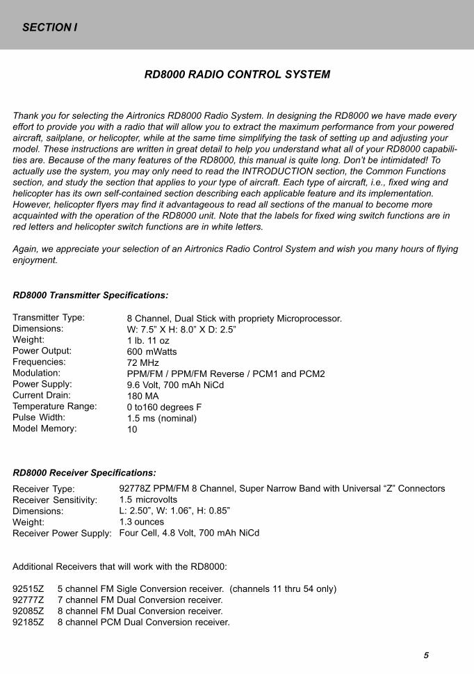
RD8000 Transmitter Specifications:
Transmitter Type:Dimensions:Weight:Power Output:Frequencies:Modulation:Power Supply:Current Drain:Temperature Range:Pulse Width:Model Memory:
RD8000 Receiver Specifications:
8 Channel, Dual Stick with propriety Microprocessor.W: 7.5” X H: 8.0” X D: 2.5”1 lb. 11 oz600 mWatts72 MHzPPM/FM / PPM/FM Reverse / PCM1 and PCM29.6 Volt, 700 mAh NiCd180 MA0 to160 degrees F1.5 ms (nominal)10
Receiver Type:Receiver Sensitivity:Dimensions:Weight:Receiver Power Supply:
Additional Receivers that will work with the RD8000:
92515Z 5 channel FM Sigle Conversion receiver. (channels 11 thru 54 only)92777Z 7 channel FM Dual Conversion receiver.92085Z 8 channel FM Dual Conversion receiver.92185Z 8 channel PCM Dual Conversion receiver.
92778Z PPM/FM 8 Channel, Super Narrow Band with Universal “Z” Connectors1.5 microvoltsL: 2.50”, W: 1.06”, H: 0.85”1.3 ouncesFour Cell, 4.8 Volt, 700 mAh NiCd
RD8000 RADIO CONTROL SYSTEM
Thank you for selecting the Airtronics RD8000 Radio System. In designing the RD8000 we have made everyeffort to provide you with a radio that will allow you to extract the maximum performance from your poweredaircraft, sailplane, or helicopter, while at the same time simplifying the task of setting up and adjusting yourmodel. These instructions are written in great detail to help you understand what all of your RD8000 capabili-ties are. Because of the many features of the RD8000, this manual is quite long. Don’t be intimidated! Toactually use the system, you may only need to read the INTRODUCTION section, the Common Functionssection, and study the section that applies to your type of aircraft. Each type of aircraft, i.e., fixed wing andhelicopter has its own self-contained section describing each applicable feature and its implementation.However, helicopter flyers may find it advantageous to read all sections of the manual to become moreacquainted with the operation of the RD8000 unit. Note that the labels for fixed wing switch functions are inred letters and helicopter switch functions are in white letters.
Again, we appreciate your selection of an Airtronics Radio Control System and wish you many hours of flyingenjoyment.
SECTION I

6
ACADEMY OF MODEL AERONAUTICS5161 East Memorial Drive
Muncie, Indiana 47302
The Academy of Model Aeronautics (AMA) is a national organization representing modelers in the United States. Weurge you to examine the benefits of membership, including liability protection in the event of certain injuries. TheAcademy has adopted simple and sane rules which are especially pertinent for radio controlled flight as the OFFICIALAMA NATIONAL MODEL AIRCRAFT SAFETY CODE, which we have partially reprinted below:
I will not fly my model aircraft in sanctioned events, airshows or model flying demonstrations until it has been proven tobe airworthy by having been previously, successfully flight tested.I will not fly my model higher than approximately 400 feet within 3 miles of an airport without notifying the airportoperator. I will give the right-of-way and avoid flying in the proximity of full-scale aircraft. Where necessary, an ob-server shall be utilized to supervise flying to avoid having models fly in the proximity of full-scale aircraft.Where established, I will abide by the safety rules for the flying site I use, and I will not willfully and deliberately fly mymodels in a careless, reckless and/or dangerous manner.I will have completed a successful radio equipment ground range check before the first flight of a new or repairedmodel.I will not fly my model aircraft in the presence of spectators until I become a qualified flyer, unless assisted by andexperienced helper.I will perform my initial turn after take off away from the pit or spectator areas, unless beyond my control.I will operate my model using only radio control frequencies currently allowed by the Federal Communications Commis-sion. (See chart below) Only properly licensed amateurs are authorized to operate equipment on amateur band frequen-cies.
72 MHz BAND by Channel and Channel Frequency
11 72.01012 72.03013 72.05014 72.07015 72.09016 72.11017 72.13018 72.15019 72.17020 72.190
21 72.21022 72.23023 72.25024 72.27025 72.29026 72.31027 72.33028 72.35029 72.37030 72.390
31 72.41032 72.43033 72.45034 72.47035 72.49036 72.51037 72.53038 72.55039 72.57040 72.590
41 72.61042 72.63043 72.65044 72.67045 72.69046 72.71047 72.73048 72.75049 72.77050 72.790
51 72.81052 72.83053 72.85054 72.87055 72.89056 72.91057 72.93058 72.95059 72.97060 72.990
INITIAL PREPARATION
PACKAGING:
The packaging of your Airtronics RD8000 Radio Control System has been especially designed for the safe transporta-tion and storage of the radio’s components. After unpacking your radio, DO NOT DISCARD THE CONTAINERS! Youshould set the packaging aside for use if you ever need to send your radio in for service, or to store your radio in caseyou do not plan to use it for an extended period of time.

7
RD8000 TRANSMITTERS FEATURES
The RD8000 narrow band PPM/FM computer radio control system is designed for the use by power model, sailplane,and helicopter pilots who demand a quality product. The RD8000 is packed with all of the capabilities that the beginneras well as the more advanced modelers demand for all three types of flying. It has the features available to get the mostout of any type of model.
Program Features for all types of models (BASIC turned ON)
10 Model MemoryStop WatchDigital TrimsServo Reversing on all channelsDual Rate on Elevator and Aileron channels(Plus Rudder on Helicopter)Large Screen Liquid Crystal Display (LCD)End Point Adjustment on all channels
Aircraft Advanced Features (BASIC turned OFF)
All of the features listed under the program with the BASIC turned ON are also included in this Advanced Featuressection.
Exponential Aileron DifferentialTrim Memeoy Landing DifferentialTrim Authority (STEP) for digital trims CrowModel Naming (3 Letters) Dual Rate AlarmFailsafe / Hold (PCM Rx only) Menu OptionsReceiver Battery Failsafe (PCM Rx only) Flap to Elevator MixLow Battery Alarm Throttle to Elevator MixIntegral System Timer Rudder to Aileron MixData Copy Aileron to Rudder MixFlaperon Mix Rudder to Elevator MixSpoilron Mix Elevator to Flap MixElevon Mix Switch ReversingV-Tail Mix 2 Compensation MixersThrottle Cut 4 Modulation ModesClick Delta MixDual Elevator Mix
Helicoter Features (BASIC) Helicopter Features (Advanced) includes Basic
Stop Watch ExponentialServo Reversing Fail Safe (PCM Rx Only)Dual Rate Elev, Ail and Rud Throttle CutServo Centering Model Naming (3 Letters)End Point Adjustment 2 Compensation MixersThrottle Curve (5 Point) in all Flight modes Integral System TimerRevo Mix (3 Point) in all Flight Modes Trim Step4 Flight Modes Switch ReversingGyro Sensitivity Adjustment in all Flight Modes Data CopyPitch Curve (5 Point) in all Flight Modes 4 Modulation ModesModel Select ClickModel Type Battery Fail Safe (PCM Rx only)Data Reset Dynamic Trim MemoryBasic ON Swash Plate Type
Basic OFFOption Menu
Model Type selectionCenter Adjustment on all channelsData ResetLCD Transmitter Voltage MeterHigh Capacity Transmitter/Receiver NiCdBatteriesAdjustable Stick Tension and LengthLow Battery, High Throttle and Power Alarms

8
The above diagram shows how to connect the components of your RD8000 system together. At this point your objectiveis to get the system operating on your workbench. Once connected you must then refer to the corresponding diagramfor your system, i.e., either AERO or HELI showing the transmitter control stick function.
NiCd BATTERY CHARGING INFORMATION:
In order to protect the charging circuit in your RD8000 transmitter, a diode has been installed to protect it from some ofthe high discharge rate “cycler’s” on the market. We recommend that you charge the transmitter battery (while installed)with the supplied ATX charger, Part # 95033Z.Should you wish to “cycle” or discharge the transmitter battery, you must first remove it from the transmitter. This allowsyou to bypass the protective diode.The following two Airtronics service items will allow you to “cycle” your RD8000 transmitter battery. See your localdealer for these items.
(1) #99704 Transmitter Charging Plug with Cable for use with your cycling device (black wire w/white tracer is positive.
(1) #97051 Transmitter Battery Cycling Adapter Cable.
Above items will also work with Airtronics Quasar, Radiant, Vanguard, VG Series and all RD Series transmitter batter-ies.
AIRBORNE SYSTEM CONNECTIONS
NiCdBattery
Switch HarnessChargeConnector
92778Z Receiver
AERO HELI
Flap
Retract Gear
Rudder
Throttle
Aileron
Elevator
Collective Pitch
Gyro
Rudder(Tail Rotor)
Throttle
Aileron(L/R Cyclic)
Elevator(F/A Cyclic)
AUX 2 AUX 2
AUX 1 AUX 1
97020Z Y Harnessor connect the SwitchHarness directly intothe Receiver
9
AIRBORNE COMPONENTS
While your systems batteries are charging, you can familiarize yourself with the airborne portion of your radio. Theairborne portion of the radio refers to any components which are mounted in your plane or helicopter and carried aloftwhen you fly. The airborne components consist of the receiver, which receives the signals from the transmitter, decodesthem, and relays the commands to the servos; the servos which are simply electronically controlled motors used tomove the controls of the plane; the NiCd battery pack which provides power for the receiver and servos to operate; andthe switch harness which allows you to turn the airborne package on and off.
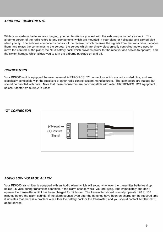
CONNECTORS
Your RD8000 unit is equipped the new universal AIRTRONICS “Z” connectors which are color coded blue, and areelectrically compatible with the receivers of other radio control system manufacturers. The connectors are rugged butshould be handled with care. Note that these connectors are not compatible with older AIRTRONICS R/C equipmentunless Adapter p/n 99399Z is used!
“Z” CONNECTOR
(-)Negative(+)Positive
Signal
AUDIO LOW VOLTAGE ALARM
Your RD8000 transmitter is equipped with an Audio Alarm which will sound whenever the transmitter batteries dropbelow 9.5 volts during transmitter operation. If the alarm sounds while you are flying, land immediately and don’toperate the transmitter until it has been charged for 12 hours. The transmitter should normally operate 120 to 150minutes before the alarm sounds. If the alarm sounds even after the batteries have been on charge for the required timeit indicates that there is a problem with either the battery pack or the transmitter, and you should contact AIRTRONICSabout service.
10
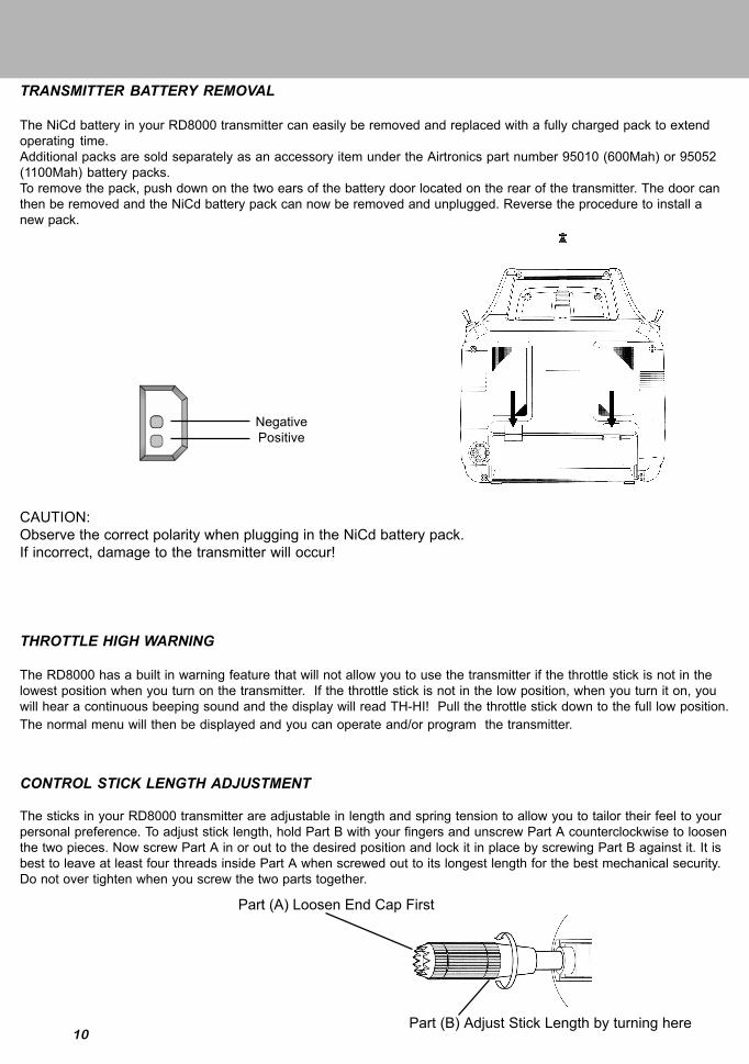
TRANSMITTER BATTERY REMOVAL
The NiCd battery in your RD8000 transmitter can easily be removed and replaced with a fully charged pack to extendoperating time.Additional packs are sold separately as an accessory item under the Airtronics part number 95010 (600Mah) or 95052(1100Mah) battery packs.To remove the pack, push down on the two ears of the battery door located on the rear of the transmitter. The door canthen be removed and the NiCd battery pack can now be removed and unplugged. Reverse the procedure to install anew pack.
CAUTION:Observe the correct polarity when plugging in the NiCd battery pack.If incorrect, damage to the transmitter will occur!
CONTROL STICK LENGTH ADJUSTMENT
The sticks in your RD8000 transmitter are adjustable in length and spring tension to allow you to tailor their feel to yourpersonal preference. To adjust stick length, hold Part B with your fingers and unscrew Part A counterclockwise to loosenthe two pieces. Now screw Part A in or out to the desired position and lock it in place by screwing Part B against it. It isbest to leave at least four threads inside Part A when screwed out to its longest length for the best mechanical security.Do not over tighten when you screw the two parts together.
THROTTLE HIGH WARNING
The RD8000 has a built in warning feature that will not allow you to use the transmitter if the throttle stick is not in thelowest position when you turn on the transmitter. If the throttle stick is not in the low position, when you turn it on, youwill hear a continuous beeping sound and the display will read TH-HI! Pull the throttle stick down to the full low position.The normal menu will then be displayed and you can operate and/or program the transmitter.
Part (A) Loosen End Cap First
Part (B) Adjust Stick Length by turning here
NegativePositive

11
TRANSMITTER STICK TENSION ADJUSTMENT
To adjust the spring tension of the transmitter sticks you need to remove the back of the transmitter case. First removethe antenna and the NiCd battery pack from the transmitter. Now remove the eight screws that hold the case back inplace, four in the main case, two in the LCD back cover and two on the handle.Once the screws are removed swing the back of the case away from the transmitter being careful of the trainer plugwiring.
There are four locations for the stick tension adjustment screws installed because the stick controlling the throttle isratcheted and has no tension adjustment. The #1 and #3 screws adjust the tension for the vertical motion of each stick.The #2 and #4 screws adjust the tension for the horizontal motion of each stick. To make the tension adjustment use asmall phillips type screwdriver to turn the adjustment screws. Turning the screw clockwise will increase the stick tension,turning it counterclockwise will decrease the tension. Once you have completed your stick adjustments, replace the caseback and install the NiCd battery pack and antenna. Be careful to line the battery charging port pins when replacing theback cover.
WARNING:
Any other modifications made to the transmitter other than adjusting stick tension will void any and all warrantiescovered be Airtronics Inc.
Screw Locations
1
2 3
4

12
TRAINER SYSTEM
The Trainer system in the RD8000 transmitter allows you to connect any two Airtronics RD series transmitters togetherfor the purpose of training a new pilot. You can also connect the RD8000 to either VG 400, VG 600, Radiant or Van-guard PPM unit. The Trainer cord to use is the ATX Part # 97100. The RD8000 is NOT compatible with Infinity 660 orQuasar units.In actual use, one of the two transmitters will serve as the Master and the second transmitter will serve as the Trainer.The Master transmitter is held by the instructing pilot, AND IS THE TRANSMITTER THAT MUST MATCH THE RE-CEIVER FREQUENCY INSTALLED IN THE MODEL! The trainer transmitter is held by the learning pilot, and does notneed to be on the same frequency as the model. The frequency of the Trainer transmitter is unimportant because theswitch of the trainer transmitter is NOT turned on during instructional flying. Normally during training, the instructortakes the model off and flies it to a reasonable altitude. While the Master/Trainer switch on the Instructors transmitter isleft in its OFF position, the Master transmitter will have full control of the model. When the instructor is ready to begintraining, he presses and holds the spring loaded switch on his transmitter which transfers control to the student.
(As long as the instructor holds his Trainer switch in the ON position, the model will respond to the commands of theTrainer transmitter sticks allowing the student to fly the model. It is not necessary for the student to hold the trainerswitch on the Trainer transmitter.)
When the instructor ceases to stop training, or if he feels that the student is in a situation that endangers the model, theinstructor can release the spring loaded switch and control of the model will immediately return to the Master transmitter.To use the Trainer system, you must plug the appropriate Trainer cable into the back of both the Master and the Trainertransmitters. Turn on the Master transmitter and the Model. The cable will energize the encoder section of the Trainertransmitter. Once you have verified that both the Master and the Trainer transmitters will control the model with the springloaded switch in the appropriate position you are ready to start training.
NOTE:
Both transmitters must be programmed identically for the trainer system to function properly. All servos must operate inthe same direction, centering, end points, and other settings such as type of Modulation must be identical.
Trainer Switch(Spring Loaded)
Master Transmitter Trainer Transmitter

13
USING THE RD8000 MICROPROCESSOR
Airtronics has invested a large amount of design effort to ensure that the powerful capabilities of the RD8000 are assimple as possible to use. This manual has been written to offer the user complete instructions for either fixed wingaircraft or helicopter models. The manual is divided into three sections. One for introduction and another for aircraft(both powered and sailplane), and one for helicopters. You only need to read the introduction section and the one thatapplies to your type of model. In most cases all of the programming of a setup is accomplished through the use of theinput keys on the RD8000 transmitter. The function(s) of these are shown below.
Note: Pressing the INC+/YES and DEC-/NO keys simultaneously will clear a setting and return it to the default value.
BAR GRAPH VOLTAGE INDICATOR
As a convenience the RD8000 transmitter provides a Bar Graph transmitter battery voltage indicator at the top of theLiquid Crystal Display screen labeled “E” and “F”. The “F” symbol indicates FULL and the “E” indicates EMPTY. You canconsider it similar to a visible gas gauge. The Bar Graph indicator is in addition to the normal battery voltage that isdisplayed on the main screen when ever you select either AIR or HELI by pushing the END key twice. When the BarGraph reads less than half you should not fly until you recharge the transmitter.
Press this key to move up in a menuPress this key to increase a value or to indicate YES
Press this key todecrease a value or toindicate NO
Press this key to return tothe previous screen
Select Flight Mode (Helicopter)Press this key to movedown in the menu
Press this key to select achannel and move to the left
Press this key to select achannel and move to the Right

14
RD8000 AERO FEATURES
FEATURES
STW (Stopwatch)
REV (Reverse)
D/R (Dual Rate)
CNT (Center)
TRM (Trim)
EXP (Exponential)
EPA (End Point Adjustment)
M-SL (Model Select)
MOD (Modulation)
TYP (Type of Model)
INT (Integral Timer)
RST (Reset)
CLK (Click)
NAM (Name)
SW-R (Switch Reverse)
CPY (Copy)
FLAPE (Flaperons)
DELTA (Elevons)
V-TAIL (Rudder and Elevator)
D/A-A (Dual Rate Alarm)
DESCRIPTION
Used as a stopwatch or tocountdown to a preset time.
Reverses the servo operatingdirection.
Adjusts servo throw. Available onElev and Ail.
Changes servo neutral position.
The LCD provides an indicator ofthe value, as well as the direction ofthe trim.
Changes the linear movement of theservo to the relation of the stickmovement. Can be set Positive orNegative.
Limits the total movement of a servoin each direction.
Select models 1~10.
Transmitting Modulation PPM/FM,PPM/Reverse FM, PCM1, PCM2.
Model Type Aircraft or Helicopter.
Used to show how long thetransmitter has been in use. Can bereset to zero.
Clears all setup data in any model tofactory default settings.
A beep sound can be heard everytime you press a transmitter key.Options Active or Inoperative.
You can use up to 3 characters toname your model.
You can reverse the default directionof all control switches.
Copy one model to another.
Activates 2 channels to be used forAilerons.
Ailerons operate as ailerons and aswell as Elevators. Used for flyingwings.
Used for V-Tail models.
Alerts you when a Dual Rate switchis on. Options On or Off.
T-CUT (Throttle Cut)
C-MIX (Compensation Mixing)
E>F (Elevator to Flap Mixing)
R>A (Rudder to Aileron Mixing)
R>E (Ruder to Elevator Mixing)
F>E (Flap to Elevator Mixing)
SPOIR (Spoilerons)
AI-DIF (Aileron Differential)
L-DIF (Landing Differential)
CR:LA (Crow Left Aileron)CR:RA (Crow Right Aileron)
OPT (Option Menu)
Step (Trim Step)
FAIL (Fail Safe)
B-F-S ( Battery Fail Safe)
BASIC ( ON/OFF )
D-EL ( DUAL ELEVATOR )
You can set the point where thethrottle can be cut using thethrottle cut-off button.
Ability to mix a master channel toanother slave channel with a C-Mix Switch.
Ability to mix Elevator to Flap.
Ability to mix Rudder to Ailerons.
Ability to mix Ruder to Elevator.
Ability to mix Flap to Elevator.
For sailplanes. Both ailerons willact as spoilers as the throttle stickis used.
Changes the total amount of throwup and down to both aileronservos independently to help stopa bad yaw.
Allows Aileron control to remaineffective when Crow or Spoilersare used (Sailplane)
Crow is used to slow the sailplanedown. Ailerons go up when flapsgo down. Left andRight Ailerons are adjustable
Advanced program allows you toturn off or on function displays.
Sets the amount of movement aservo will move with one beep ofthe trim.
You can preset a default controlinput when aircraft loses it’s signalfrom the transmitter. Only workswith a PCM receiver.
Will bring the throttle servo to idlewhen the airborne battery reachesa predetermaned low voltage. Onlyworks with a PCM receiver.
Turn Basic menu on or off
Activates 2 channels to be usedfor dual elevator servosCh 1 left servoCh 7 Right servo
FEATURES DESCRIPTION

15
RD8000 HELI FEATURES
FEATURES
STW (Stopwatch)
REV (Reverse)
D/R (Dual Rate)
CNT (Center)
TRM (Trim)
EXP (Exponential)
EPA (End Point Adjustment)
M-SL (Model Select)
MOD (Modulation)
TYP (Type of Model)
INT (Integral Timer)
RST (Reset)
CLK (Click)
NAM (Name)
SW-R (Switch Reverse)
CPY (Copy)
T-CUT (Throttle Cut)
DTM (Dynamic Trim Memory)
GYR (Gyro)
CV-P# (Throttle Curve)
CV-P# (Pitch Curve)
RV (Revolution Mixing)
FAIL (Fail Safe)
C-MIX (Compensation Mixing)
STEP (Trim Step)
B-F-S (Battery Fail Safe)
SWH (Cyclic Type)
BASIC ( ON/OFF)
OPT (Option Menu)
DESCRIPTION
Used as a stopwatch or to countdown to a preset time.
Reverses the servo operating direction.
Adjusts servo throw. On Elev, Ail and (Rud in Heli Mode)
Changes servo neutral position.
The LCD provides an indicator of the value, as well as the direction of the trim.
Changes the linear movement of the servo to the relation of the stick movement. Canbe set Positive or Negative.
Limits the total movement of a servo in each direction.
Select models 1~ 10.
Transmitting Modulation PPM/FM, PPM/Reverse FM, PCM1, PCM2.
Model Type Aircraft or Helicopter.
Used to show how long the transmitter has been in use. Can be reset to zero.
Clears all setup data in any model to factory default settings.
A beep sound can be heard every time you press a transmitter key. Options Active orInoperative.
You can use up to 3 characters to name your model.
You can reverse the default direction of all control switches.
Copy one model to another.
You can set the point where the throttle can be cut using the throttle cut off button.
Memorizes trims in each flight mode.
Gyro sensitivity for each flight mode
To setup a curve in all flight modes.
To setup a curve in all flight modes.
Tail rotor offset mixing
You can preset a default control input when aircraft loses it’s signal from thetransmitter. Only works with a PCM receiver.
Ability to mix a master channel to another slave channel with a C-MIX switch.
Sets the amount of movement a servo will move with one beep of the trim.
Will bring the throttle servo to idle when the airborne battery reaches a predetermanedlow voltage. Only works with a PCM receiver.
5 Cyclic Options (Normal, CP3F, CP3B, CP4F, CP4B)
Basic menu ON or Off
Advanced program allows you to turn off or on function displays.

16
SECTION II COMMON FUNCTIONS
The following functions are common and are applicable to both Aircraft and Helicopter sections of this manual. TheLiquid Crystal Display shows an Aero model selected; however, a similar screen will be displayed when a Helicoptertype model is selected.
NOTE: Switches labeled with red lettering are for aircraft and blue lettering is used for helicopter.
IMPLEMENTATION OF CONTROL FUNCTIONS
In this section you will learn how to implement the control functions and tailor the servo movement and centering foreach control. Pressing the END key on the front panel several times will bring you to the following screen, i.e., the initialscreen that indicates the current model type and number, PPM modulation and the transmitter NiCd battery packvoltage.
Press the (CH +) key to obtain the STW screen. The Elevator channel will appear on the upper part of the screen. Themodel number and aero will be present on the left side and the stop watch will indicate zero since no time has beenprogrammed.
REV (SERVO REVERSING)
The RD8000 allows you to electronically REVERSE the direction of rotation for each of the servos in use. This allowsyou to hook up your control linkages and pushrods in the most mechanically desirable manner without regard to thedirection of servo movement. After installing your linkages check to see if any of the controls move in the wrongdirection when you move the controls. If so proceed as follows for reversing the elevator channel. Reverse for all otherchannels are done the same way.
Press the FUNCTION down key to arrive at the following screen:
If the Elevator servo moves in the wrong direction, press the INC +/YES key to change the direction.

17
CNT (CONTROL CENTERING)
Your RD8000 allows you to fine-tune the CENTER or neutral position of all flight control servos. After hooking up yourcontrols and mechanically centering all linkages to the approximate positions, press the FUNCTION down key to arriveat the following screen for the Elevator control.
(Note that the Aileron, Throttle, Rudder, Flap, AUX-1 and AUX-2 centering operates in the same manner when youselect that channel on the upper part of the screen. You can move across to the CNT function of each channel as wellas some of the other functions by pressing the (CH+ ) key.
By pressing the INC+/YES or DEC-/NO keys you can vary the value from 0 to + or - 100%. Default is 0%
IMPORTANT NOTE:It is desirable to adjust the control linkages as close as possible to the correct center positions, then use the CNT(CENTER) commands to “Fine-tune” the exact position of the control surface when the transmitter control is in neutral.
Using a large amount of electronic centering adjustments will decrease the total throw available for that channel. Inparticular, centering adjustments greater than + or - 50% will tend to make the extreme stick position on one end lessresponsive!

18
If you want to “UNDO” all of your programmed parameters at one time, you can use the RST function. However, becertain that is what you want to do, since this function will reset all settings to the factory default settings. The RSTfunction will only affect the specific model that you have selected. ALL OTHER Models in memory are unaffected bythe RST function.
Press the END key to select the initial AR 1 screen that indicates the Transmitter NiCd pack battery voltage. Now, pressthe CH + to access the STW (Stopwatch) screen. This screen allows you to move up and down as well as left and righton the screen in the RD8000 program.
RST (DATA RESET)
To RESET ALL DATA for this model to default settings press the (CH +) key and the screen will flash YES. Now, pressthe INC +/YES key and the screen will indicate OK! All paramameters on this specific model number have now beenreset to default values. Press the END key twice to return to the STW screen.
Press the CH + key several times to move across the CH indicator portion of the screen until it reads “etc”. Now, pressthe FUNCTION down key three times to move down in the menu until you reach the RST (Data Reset) screen.

19
HOW TO SELECT MODEL SET-UPS: M-SL (Model Select)
The RD8000 has built in memory to store ten model setups in any combination of model types. To use or modify one ofthe model setups you first must select M-SL in the etc menu. Assume that you want to select a second model. To doso, press the END key to bring up the initial screen that indicates transmitter voltage and model number.
Press the (CH +) key to scroll to “etc”. Use the FUNCTION down key to select MSL. Next press the INC +/YES key andthe screen will flash MSL to indicate you can select a second model. Press the INC +/YES key again to select the nextor following model such as AR2.
Press the END key three times to return to the initial screen which will show the model number and the transmitterbattery voltage reading.
NOTE: if the model type is incorrect, i.e., HELI rather than AERO, continue with the model selection procedure. Themodel type can then be selected on the TYP screen.
TYP (MODEL TYPE)To select the type of model you wish to program, press the (CH+) key to scroll to “etc”. Next press the FUNCTION key toselect TYP. Now press the (CH+) key to select the next model type, either HELI or AERO. The screen will flash YES withthe type of model indicated on the LCD display. To confirm your selection, press the INC+/YES key and the screen willindicate OK!
Press the END key three times to return to the inital screen that will then show your model number/type and transmitterbattery voltage.

20
STW (STOPWATCH)
The RD8000 offers a built-in timer and allows the pilot to use the stopwatch function in either elapsed time mode or in acountdown mode of operation. To use the stopwatch, press either the (CH -) or the (CH +) key to select “etc” on theChannel indicator display.
Now press the FUNCTION down key to scroll through the various screen’s until you find the STW screen with theflashing >indicator. This is where you can set your stopwatch countdown time. The STW (set) screen is just above theINT screen as shown on the Menu Structure, page 32.
Use the INC +/YES key to set a value for the Start of your count down; as an example set it at 10.00 minutes. Thescreen will look like the following illustration. If you want to decrease the time, use the DEC - /NO key. If you want toclear the time, press the INC +/YES and the DEC - /NO keys simultaneously.
You can now start the stop watch when you are on any of the channel indicator screens that displays the STW screenand the time you previously programmed. Press the INC+/YES key to start or stop the countdown. When the timereaches 10 seconds, a tone will be heard and one will also be heard every second as it counts down to zero. When thetimer reaches zero, a steady tone will be heard and it will start counting up. Press the INC+/YES key and DEC-/NO keysimultaneously to reset the timer to your previously programmed time.
Note: To program a time, you must be in the BASIC OFF mode of operation.

21
INT (INTEGRAL TIMER)
The Integral Timer function of the RD8000 is activated each time the transmitter power switch is turned on, and contin-ues to time up to 99 hours and 59 seconds at all times when the transmitter is turned on. This time will give an excel-lent indication of how many hours of actual use you RD8000 transmitter has accrued. Or, you may wish to re-set thetimer to zero at certain intervals, for instance, each time you charge the transmitter NiCd battery pack.
The INT (Integral Timer) function is located in the “etc” column of the menu, directly below STW (set). Use theFUNCTION down key to access the INT screen. Note that it will have some indication of how long the transmitter hasbeen operating. It may look like the following screen, but with a different time shown. The time will show a change foreach elapsed second and minute. If you want to reset the Integral Timer to Zero, press the INC +/YES and the DEC -/NO keys simultaneously.
If you desire, you can display the Integral Timer function instead of the STW (stop watch) function on all of the Channelscreens. To do so while you are in the INT screen, press the (CH +) key to obtain the following screen.
Press the INC +/YES key and the bottom line of the screen will change from INH (inhibit) to read ACT (active). You canpress either the DEC -/NO key or the INC +/YES key to change it back to INH. Most pilots prefer to have the Stopwatch function displayed on all of their Channel screens, rather than the Integral Timer, therefore, they leave the IntegralTimer DSP at INH (inhibit). Press the END key twice to get back to the top of the “etc” menu column.
22
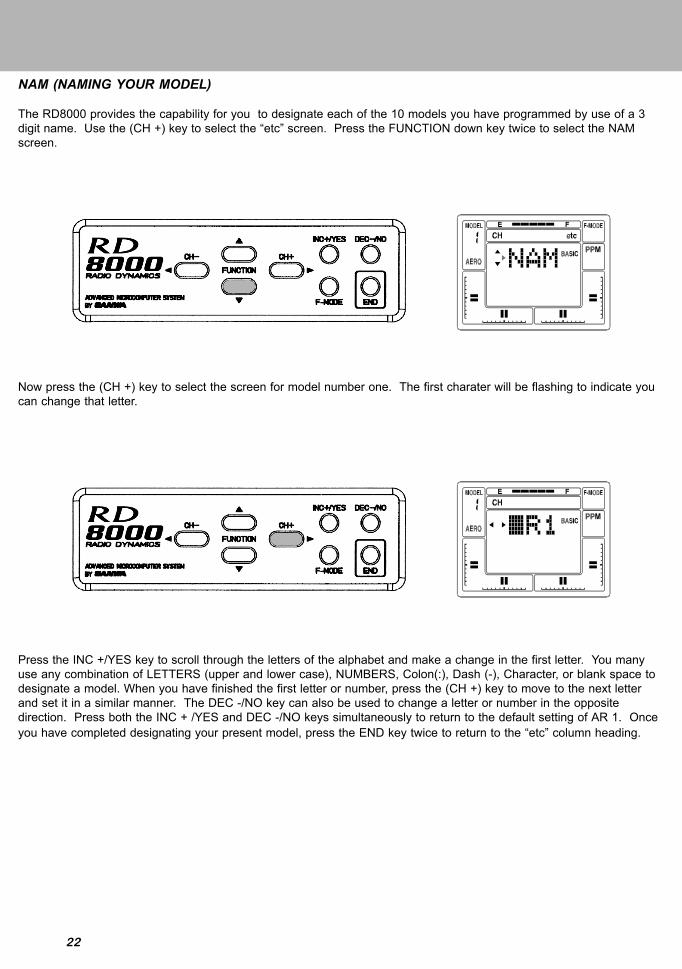
NAM (NAMING YOUR MODEL)
The RD8000 provides the capability for you to designate each of the 10 models you have programmed by use of a 3digit name. Use the (CH +) key to select the “etc” screen. Press the FUNCTION down key twice to select the NAMscreen.
Now press the (CH +) key to select the screen for model number one. The first charater will be flashing to indicate youcan change that letter.
Press the INC +/YES key to scroll through the letters of the alphabet and make a change in the first letter. You manyuse any combination of LETTERS (upper and lower case), NUMBERS, Colon(:), Dash (-), Character, or blank space todesignate a model. When you have finished the first letter or number, press the (CH +) key to move to the next letterand set it in a similar manner. The DEC -/NO key can also be used to change a letter or number in the oppositedirection. Press both the INC + /YES and DEC -/NO keys simultaneously to return to the default setting of AR 1. Onceyou have completed designating your present model, press the END key twice to return to the “etc” column heading.

23
0
25
50
75
100
0 25 50 75 100
0
25
50
75
100
0 25 50 75 100
Serv
o Tr
avel
Serv
o Tr
avel
Stick Deflection Stick Deflection
LINEAR THROW EXPONENTIAL THROW
EXP (EXPONENTIAL)
The RD8000 allows the pilot to choose two settings for Exponential throw for each of the primary flight channels,Elevator, Aileron (and Rudder in helicopter mode).
Exponential throw is primarily used to “soften” or decrease the control stick sensitivity of a control around the neutralpoint. With Exponential disabled, a control funtion servo will move in an amount proportional to the amount of controlstick deflection, i.e., 50% stick deflection will result in 50% servo travel; 75% stick deflection will result in 75% servotravel.
Exponential settings DO NOT change the amount of travel available at 100% stick deflection, but rather it changes theamount of the servo travel that will occur with stick deflections less than 100%. The first 25% of stick deflection may beset to result in only 10% of total servo throw making the control less sensitive around neutral. See the followingillustrations.
If you have used Exponential functions before, you will want to start with a small amount of Exponential (10 to 20%) todetermine wheather you like this sort of control response. Exponential is most useful where strong control response isdesired at extreme stick positions but softer response to small stick movement is desired in order to make very accuratesmall corrections to flight path.
The switch positions for Exponential #1 and Exponential #2 correspond to the Dual Rate switch positions of Elevatorand Aileron. Exponential #1 is with the Dual Rate switch in the down i.e., Off position. Exponential #2 is with the DualRate switch UP i.e.,ON position. (Note however that you can leave the Dual Rate adjustments for Elevator and Aileronset at 100% which is no rate, so that switching a Dual Rate switch ON will activate Exponential only.
NOTE: Setting the Exponential with a positive number will make servo movement soft in the neutral area of the stickmovement. Setting the Exponential with a negative number will make servo movement faster in the neutral area andsofter at the end of the stick travel.
24
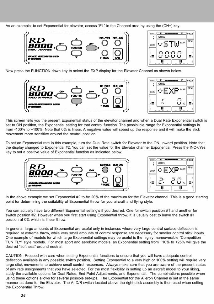
As an example, to set Exponential for elevator, access “EL” in the Channel area by using the (CH+) key.
Now press the FUNCTION down key to select the EXP display for the Elevator Channel as shown below.
This screen tells you the present Exponential status of the elevator channel and when a Dual Rate Exponential switch isset to ON position, the Exponential setting for that control function. The possibilble range for Exponential settings isfrom -100% to +100%. Note that 0% is linear. A negative value will speed up the response and it will make the stickmovement more sensitive around the neutral position.
To set an Exponential rate in this example, turn the Dual Rate switch for Elevator to the ON upward position. Note thatthe display changed to Exponential #2. You can set the value for the Elevator channel Exponential. Press the INC+/Yeskey to set a positive value of Exponential function as indicated below.
In the above example we set Exponential #2 to be 20% of the maximum for the Elevator channel. This is a good startingpoint for determining the suitability of Exponential throw for you aircraft and flying style.
You can actually have two different Exponential setting’s if you desired. One for switch position #1 and another forswitch position #2. However when you first start using Exponential throw, it is usually best to leave the switch #1position at 0% which is linear throw.
In general, large amounts of Exponential are useful only in instances where very large control surface deflection isrequired at extreme throw, while very small amounts of control response are necessary for smaller control stick inputs.One example of models for which large Exponential settings may be useful is the highly maneuverable “CompetitionFUN FLY” style models. For most sport and aerobatic models, an Exponential setting from +10% to +25% will give thedesired “softness” around neutral.
CAUTION: Proceed with care when setting Exponential functions to ensure that you will have adequate controldeflection available in any possible switch position. Setting Exponential to a very high or 100% setting will require verylarge stick movements to achieve small control responses. Always make sure that you are aware of the present statusof any rate assignments that you have selected! For the most flexibility in setting up an aircraft model to your liking,study the available options for Dual Rates, End Point Adjustments, and Exponential. The combinations possible whenusing these options allows for several possible set-ups. The Exponential for the Aileron Channel is set in the samemanner as done for the Elevator. The AI D/R switch located above the right stick assembly is then used when settingthe Exponential Throw.

25
MOD (MODULATION)
An extremely versatile feature of the RD8000 transmitter is the capability to select 4 different types of modulation. Theseare PPM/FM for standard FM receivers and PM/FM-Reverse for “other brand” receivers, PCM1 and PCM2 for AirtronicsPCM Receivers. To access the Modulation screen, press either the (CH –) or (CH +) key to select the “etc” screen.
Next, press the FUNCTION down key to select the MOD (modulation) screen. It will show PP indicating the presentselection is PPM/FM.
If you want to change the Modulation, press the INC +/YES key and the presentation will change to the following screen.Note that the small Modulation Indicator on the right side of the screen will also show the present modulation selectionwhen it is changed, except when you select PPM/FM Reverse.
Press both the INC +/YES and DEC -/NO keys simultaneously to return to the default PP (PPM/FM) modulation. Pressthe END key to return to the STW screen.

26
CPY (DATA COPY)
A valuable feature of the RD8000 is the Data Copy Function. With this function the entire set of control parameters forone aircraft can be ‘copied’ from one model set-up into another. (For instance, if you have your aircraft program inModel #1 and nothing in Model #3, you can copy the Model #1 program into Model #3 with the copy function.
Having copied your control set-up, you can now use MSL (Model Select) to access the Model #3 program and thenmake control changes to that set-up. This allows you to experiment with different control options without changing youroriginal parameters (in this example Model #1).
To use the CPY (copy) function, select “etc” on the Channel indicator using either the (CH –) or (CH +) key. (notethat you must be on the STW screen to move horizontally across the screen to “etc”).
Press the FUNCTION down key to select the CPY (copy) Function.
For this example, assume you want to copy the set-up of Model #1 (which you selected), to Model #3. The first numberon the screen indicates the model number of the model you are copying. The second number indicates the destinationof the model being copied. Press the INC +/YES key to change the destination for the copy to indicate Model #3. Notethat one of the small triangles is blinking which indicates there is another screen associated with this function.
27
On the previous screen, the destination has been set to Model #3. MAKE CERTAIN that this model setup is not oneyou wish to save, because when you copy the Model #1 set-up into Model #3, all data that was in Model #3 is replacedwith the Model #1 data! At this point Model #3 data is still intact, so if you wish to change the destination for the copieddata, do so before proceeding.
Having selected both the data source (Model #1) and the desired destination (in this example Model #3), you can nowproceed to confirm the copy function.
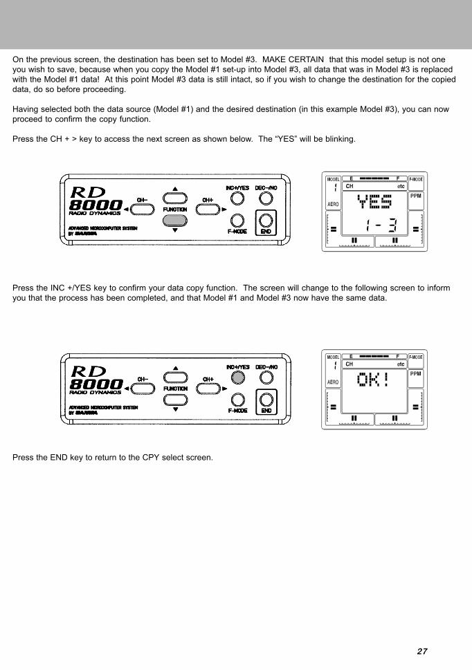
Press the CH + > key to access the next screen as shown below. The “YES” will be blinking.
Press the INC +/YES key to confirm your data copy function. The screen will change to the following screen to informyou that the process has been completed, and that Model #1 and Model #3 now have the same data.
Press the END key to return to the CPY select screen.

28
SW-R (SWITCH REVERSE)
The SW-R Function allows you to reverse the action of the six toggle switches located on your RD8000 transmitter. Thedefault of the SW-R Function is in the NOR (normal) position. CAUTION! The switch reversal function is not selective.If you change it from NOR (normal) to REV (reverse), all switches will be reversed in their action!
To access the SW-R Function, select “etc” on the Channel indicator using either the (CH -) or the (CH +) key. ( Note thatyou must be on the STW screen to move horizontally across the screen to“etc”)
Press the FUNCTION down key to scroll down to the SW-R (switch reverse) screen.
Now, press either the INC +/YES or the DEC -/NO key to change the indication from NOR to REV. All switches on thetransmitter are now reversed in their function. Press END to return to the STW screen.
NOTE: All switches as a NOR normal default (switch off position): Both top toggle switches in the up position and allfour slide switches on the front of the transmitter are down or pulled towards you. Using the SW-R feathure will makethe default off position: Both toggle switchs down and all four slide switches pushed forward or up position as defaultoff.

29
CLK (CLICK)
The RD8000 transmitter normally is set to emit an audio tone when ever the programming keys are pressed, whenvalues are changed and when the stop watch function is started, stopped or reaches the final ten seconds of count-down.
It is possible to disable the “Click” or audio tone, using software settings. When the “Click” tone is disabled, ONLY thestop watch count-down will still cause an audio tone to be emitted.
To set or disable the “Click” function, select “etc” on the Channel indicator using either the (CH –) or the (CH +) key.
Press the FUNCTION down key to access the CLK (CLICK) screen.
Press the INC +/YES key to change the indication from ACT to INH, to disable the Click function. (pressing either theINC +/YES or the DEC -/NO key will toggle the function between “INH and “ACT” settings
Press the END key to return to the STW screen.

30
T-CUT (THROTTLE-CUT)
Another useful function provided by the RD8000 for engine powered models is T-CUT, Throttle Cut. Normally you setyour throttle stick in the extreme low position and use EPA and the digital trim to obtain a steady low engine idle speed.However, if you want to stop the engine at the end of the flight you would have to use the throttle digital trim and laterre-trim for proper idle. The T-CUT function solves this problem by providing a push button that, when pushed, overridesthe throttle sticks low throttle position and drives your throttle servo to a lower position, stopping the engine. The throttlestick must be in the low position for the throttle cut to function.
In order to use T-CUT, press either the (CH -) or the (CH +) key to select TH on the Channel indicator.
Next, press the FUNCTION down key several times to obtain the following screen.
Press the DEC -/NO key to set a value of –100%. Place the throttle stick in the extreme low position. Press and holddown the Throttle Cut push button located above the elevator/aileron stick assembly. The throttle servo will then rotatefurther to close the engines carburetor and stop the engine.

31
Elevator Dual Rate Switch
Trainer Switch
Throttle (U/DRudder (L/R)
Throttle Digital Trim
Rudder Digital Trim
Panel Input Keys
Retract Switch
RD8000 Transmitter - AIRCRAFT
Liquid Crystal Display
AUX-2
Aileron Dual Rate Switch
Throttle Cut Switch
Elevator (U/D)Aileron (L/R)
Elevator Digital Trim
Aileron Digital Trim
Main Power Switch
Flap Switch
92778Z Receiver Channel Assignments
Receiver Plug Number12345678/B
Plug in Servo For:ElevatorAileronThrottleRudderGearFlap or 2nd Aileron ServoAUX 1AUX 2 / Battery
C-MIX 1, 2AUX-1

32
AIRCRAFT BASIC MENU STRUCTURE
(Rx Channel) CH EL AL TH RU G P/F 7 8 etc
Use the four center buttons in the function panel to navigate through the menu’s. (UP / DOWN / LEFT / RIGHT)
AIRCRAFT ADVANCED MENU STRUCTURE
STWREVD/RCNTEPA
STWREVD/RCNTEPA
STWREVCNTEPA
STWREVCNTEPA
STWREVEPA
STWREVCNTEPA
STWREVCNTEPA
STWREVCNTEPA
STWM-SLTYPRST
BASIC
(Rx Channel) CH EL AL TH RU G P/F 7 8 etc
STWTRMREVD/REXPCNTEPAE>FFAIL
STWTRMREVD/REXPCNTEPAA>RFAIL
STWTRMREVCNTEPAT>E
T-CutFAIL
STWTRMREVCNTEPAR>AR>EFAIL
STWREVEPAFAIL
STWTRMREVCNTEPAF>EFAIL
STWREVCNTEPAFAIL
STWREVCNTEPAFAIL
STWM-SLNAMMAS1SLV1E>E1MAS2SLV2E>E2STWINT
STEPTYP
SW-RCPYRSTMODCLK
B-F-SFlapeSpoirDeltaV-TailD-EL
Al-DIFL-DIFCR:LACR:RAD/R-ABASICOPT

33
PROGRAMMING FOR AIRCRAFT
INITIAL SET-UP OF TYP (MODEL TYPE)
When you receive your RD8000 unit the transmitter is preprogrammed for both fixed wing aircraft model’s as well as forhelicopter models as follows:
If you fly only fixed wing model aircraft, you can change model’s 2, 4, 6, 8 and 10 to aircraft.
Turn the transmitter power ON and press the END key untill you come to the default main screen. The inital screen willshow AR1 which indicates the aircraft type as well as showing the NiCd battery voltage.
Press the (CH+) key to scroll across the CH (channel) indicator on the screen to “etc”.
Press the FUNCTION down Key once to access the MSL (model select) screen.
Model #1 is setup AERO Model #5 is setup AERO Model #9 is setup AEROModel #2 is setup HELI Model #6 is setup HELI Model #10 is setup HELIModel #3 is setup AERO Model #7 is setup AEROModel #4 is setup HELI Model #8 is setup HELI

34
Next, press the INC+YES key until the screen reads HL2 (heli model 2). Now press the END key and the screen willshow that you have selected model number two which is a helicopter setup. However, since you are a fixed wing aircraftpilot, you want all of the transmitter setups to be fixed wing aircraft. The TYP (type) of aircraft must be changed fromHeli to Aero.
TYP (Type of Model)
To change the type of model, press the FUNCTION down key to select the TYP (model type) screen.
Note that one of the small triangular indicators will be blinking to show that you should press the (CH+) key. Therefore,press the (CH+) key and the screen will change to AERO with a flashing YES.
To confirm the change of aircraft type, press the INC+/YES key. The screen will then change to read OK! As shown onscreen below to indicate the model type has been changed to AERO for model #2. Press the END key twice to return tothe STW screen. The same procedure as noted above can be used to change model #4, 6, 8 and 10 from HELI toAERO.

35
D/R (DUAL RATE)
Dual Rate adjustments allow you to switch from your “standard “ control deflection to a reduced amount of throw bysimply flipping a switch. The Actual speed of signal processing and servo movement are not affected by the Dual Ratesettings, only the amount of total throw available.
The RD8000 allows Dual Rate settings for Aileron and Elevator. To access the Dual Ratesetting for Elevator when you are on the STW or REV screen, press the FUNCTION down key to reach this screen.
The screen tells you the present rate status, and when a Dual Rate is set to the ON position, the alternate rate for thatcontrol function that is presently set in the program. It is important to understand that the term “Dual Rate” is usedbecause it is an old and familiar description. We are showing an example for the Elevator channel, however, all of theother channels are set in the same way.
The Dual Rate setting can be varied from 0 to 150%. Default for Dual Rate 1 is 100%. We recommend you leave it atthat setting and only change the setting for Dual Rate 2, i.e., when the Dual Rate Switch on the upper left side of thetransmitter panel is turned ON. The normal convention for Dual Rate reduced throw is the switch in the UP position toTurn ON Dual Rate. When you do so, note that the Screen will appear as follows. Press the INC +/YES or DEC -/NOkey to increase or decrease the value. An initial setting of 50% is a good starting point and you can tailor it laterfollowing a test flight.
The Dual Rate switch for Aileron is located above the right stick assembly and is labeled AI D/R. Aileron Dual Rate isprogrammed similar to that as done for Elevator. To set it for Aileron, place the AI DR switch in the upper position anduse the DEC -/NO key to reduce the value shown on the screen to something less than 100%.
CAUTION: Prior to taking off your model, check the position of both of your Dual Rate switches to make sure they arein the position you want!

36
EPA (END POINT ADJUSTMENT)
The RD8000 allows you to adjust the “End Points”, or travel limits, for all flight channels.
In general, it is best to use as close to 100% servo throw as possible. This allows for the best possible resolution andcentering of all control surfaces. However in some cases it is not possible to use full servo movement such as thoseinstances where short control horns must be used because of aircraft design considerations, or with fixed length controlhorns such as a throttle arm.
Assume we want to adjust the EPA of the Elevator channel servo. To electronically do so, we first bring up the STW(stopwatch) screen as previously instructed in INITIAL SETUP. Next press the FUNCTION down key until the EPAscreen appears for the Elevator channel.
The EPA of the Elevator channel can be adjusted from 0% to 150%. By moving the elevator stick up and down, you willsee the LCD arrow change according to the direction you are moving the stick. To set the UP EPA, move the stick backpast the neutral position and release the stick. You can increase or decrease the amount by using the (INC+) or (DEC-)function keys.
Note that you can move across the menu using the (CH+) or (CH-) keys to adjust EPA for all other channels.To adjust the EPA on Gear and Flap channels simply move the toggle switch up or down and adjust the EPAaccordingly.

37
G (Landing Gear End Points)
In most cases, (almost all cases in the past) the total servo throw for the landing gear function could not be set by thetransmitter, because most retract servos are SWITCHED (non-proportional) servos. With these servos, mechanicaladjustment was the only method available to ensure proper operation of the retracts.
Airtronics now offers a high Torque PROPORTIONAL retract servo, p/n 94739. With this servo and the RD8000transmitters, End Point Adjustments for the retract servo are possible, independently setting the “Down” and “UP” lockpositions in mechanical retracts, and precise adjustment of the air valve in pneumatic retracts.
To use this function, select the EPA function as shown on the previous screen.Press the (CH +) key to scroll across the Channel indicator on the screen until you reach G (Landing Gear).
Note that you must set the value for UP and Down landing gear by use of the INC +/YES and DEC -/NO keys. Activatethe Landing Gear toggle switch located on the upper left top of the transmitter when setting the values for the LandingGear. You can vary each one from 0% to 150%. The default values for Landing Gear are –125% and +125%. To restorethe landing gear channel to the default values, press the INC and DEC keys simultaneously.
Press the END key to return to the STW screen.

38
TRM (TRIM MEMORY)
The RD8000 offers the Trim Memory Function on all four of the flight control channels and the Flap Channel. TrimMemory for Elevator, Aileron, Throttle, and Rudder is input by the Digital Trim keys. It can also be set when you use theINC +/YES or DEC -/NO keys to input trim.
Any trim that you set while your model is in flight by use of the Digital Trim keys will automatically be stored in memoryfor that specific channel and model.
The Trim value in % that you set during flight is shown on the TRM screen for each Channel. In addition, there are bargraph indicators on the screen at all times that visually show how much trim has been set for Elevator, Aileron, Throttleand Rudder channels.
3 POSITION FLAPS (FLAP SWITCH)
Using channel 6 as a flaps only channel, you are able to adjust the 3 flap positions. Up 0% flaps, 50% flaps and 100%full flaps down.
By starting in the default screen, push the function CH+ key to move the curser to the right untill you reach the P-F. Allof your flap adjustment is done with the CNT and EPA.
You will be using your EPA and servo centering to change the persentages of how much flap you would like. First movethe 3 position switch to the middle postion. This will position the servo to its center position. With out using the servocentering feature, install the servo arm so the arm is as close to 90 deg as posible.
Now move the 3 poistion flap switch to the up postion and setup your linkage so your flaps will be at 0%.After your linkage is set you can now move the 3 position switch to the middle. This will move your flaps down to the50% position. Moving the 3 position switch to the last or full down position will give you full 100% flaps down.
With the 3 position swtch in the mid position, you can adjust the amount of flaps down in this position with the servocentering feature. REMEMBER! changing the servo centering will change both up and down end points. Besure toreadjust both end points after you change the servo centering.
After adjusting the mid flap position, you can now adjust both the up and full down positions with the EPA feature.

39
FLAPE (FLAPERONS)
The Flaperon function can be used to obtain two separate aileron channels with a servo in each wing. It can also beused so that the strip ailerons act as flaps and deploy in a downward direction to create both lift and drag. In thefollowing example, the ailerons will be programmed to act as flaps that are controlled by the Flap/FL-EL switch.
Press the (CH –) or the (CH+) key to select “etc” on the Channel indicator.
Next, press the FUNCTION down key several times to see the following screen.
Now, press the INC +/YES or the DEC -/NO key to set the FLAPE function to Active. The aileron stick will now operatetwo servos on receiver channels #2 and #6. Press the END key to return to the STW screen at the top of the menu.
Bottom View
Left Wing Channel #2Right Wing Channel #6
Servo linkage must be on the outer side of the servo when mounted like above example.

40
Press the (CH –) key to select P-F on the CHannel indicator.
Use the FUNCTION down key to scroll down to FLAP EPA (endpoint adjust). Note that the default setting is –100%.Range of adjustment is from -150% to +150%. Press either the INC +/YES or the DEC -/NO key to change the valueand / or polarity of the function. The FLAP/FL-EL switch located on the top-right of the transmitter activates theFlaperons. To disable the Flap switch, set the Flap EPA at 0%.
Note that if the ailerons go up when the Flap switch is activated, change the polarity of the programmed value. Use theFLAP TRM (trim) function to fine tune flap operation.

41
ALARMSD/R-A(DUAL RATE ALARM)THROTTLE STICK HIGH
The RD8000 offers an “ALARM” function to warn you if you turn your transmitter on while a Dual Rate Switch is acti-vated, and another to warn you if you turn the transmitter on while the Throttle Stick is in any position other than Full-Low throttle. TH-Hi! Will be displayed on the LCD screen until you place the Throttle stick in the full-low position.
To activate the D/R-A (Dual Rate alarm), press the (CH –) or the (CH +) key to select “etc” on the Channel indicator.
Press the FUNCTION down key several times to scroll down the menu items and select the D/R-A screen.
Next, press either the INC +/YES or the DEC -/NO key to set D/R-A to ACTive.
If a Dual Rate switch is in the ON position when you turn ON the transmitter, an audio tone signal of 3 beeps will occurapproximately every 15 seconds until you turn off a dual rate switch.
If you wish, you can turn off the Dual Rate alarm by pressing either the INC +/YES or the DEC -/NO key to change D/R-A to INHibit.
Note that the High Throttle Stick alarm is always active.
NOTE: The RD8000 transmitter will also sound an alarm if the power switch is left on with out any movment of thecontrols for a period of time that exceeds 15 minutes. The screen will show PWR!.

42
DELTA (ELEVONS)
DELTA mix can be used in a flying wing type model to provide ELEVON control, where the elevator and aileron func-tions are combined.
To access the DELTA function, use either the (CH –) or the (CH +) key to select the STW screen.
Press the FUNCTION down key to scroll down to the DELTA screen.
Now press the INC + /YES key to change the display to ACT(Active). Note that you cannot have FLAPE (Flaperon)Active when DELTA is Active and vice versa. When DELTA is Active, you will have two channels assigned for ELEVONcontrol. Plug these two servos into channels #1 and #2 of your receiver. The two servos will now respond to movementof the elevator/aileron control stick. End Point Adjustments for elevator and aileron can then be made for the amountof throw required.
Press the END key to return to the STW screen.

43
A>R (AILERON-RUDDER MIX)
The RD8000 provides you with the capability to program your aircraft so that Aileron stick deflection will also cause therudder servo to respond in the same direction, (right aileron=right rudder). This automatic coordination of rudder withaileron is useful in many high wing/scale models that suffer from adverse yaw with aileron application. (Note that therudder servo will still respond to rudder stick movement as well as with aileron stick movement).
To use A>R (aileron-rudder) mixing, first access the AL (aileron) channel on the Channel indicator.
Next, press the FUNCTION down key to select the A>R display.
Press the INC +/YES key to adjust the amount of mixing that will occur.
You can now activate the AL>RU mix switch, located above the throttle/rudder stick assembly, to turn-on or off theAL>RU mix function. Press the INC +/YES and DEC -/NO keys simultaneously if you desire to reset A>RU to 0%.

44
V-TAIL (RUDDER-ELEVATOR MIX)
The RD8000 transmitter has the ability to control sailplanes or powered models that utilize a V-Tail control system. Inthese aircraft the two tail controls perform both as elevators and as rudders. Two servos and two channels (receiverchannels #1 and #4 are required for V-Tail operation).
To select the V-Tail operation, first press either the < CH - or the CH + > key to access the “etc” channel indicator.
Next, press the FUNCTION down key to scroll down to the V-TAIL display.
Press the INC +/YES key to see the following screen which will activate the V-TAIL function. If you press the DEC -/NOor the INC +/YES key you can toggle from INH (Inhibit) to ACT (Active). You can use the Rudder and Elevator ServoRev (Reverse) and EPA (End Point Adjustment) functions to fine tune your set-up.
If you desire, you may use the Aileron>Rudder mixing function to allow operation of the V-Tail rudders with the rightaileron control stick. See AL>RU mixing, page 43.
45
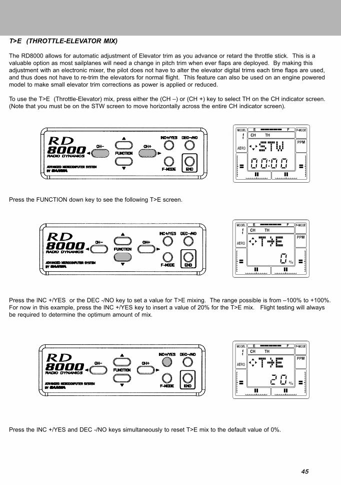
T>E (THROTTLE-ELEVATOR MIX)
The RD8000 allows for automatic adjustment of Elevator trim as you advance or retard the throttle stick. This is avaluable option as most sailplanes will need a change in pitch trim when ever flaps are deployed. By making thisadjustment with an electronic mixer, the pilot does not have to alter the elevator digital trims each time flaps are used,and thus does not have to re-trim the elevators for normal flight. This feature can also be used on an engine poweredmodel to make small elevator trim corrections as power is applied or reduced.
To use the T>E (Throttle-Elevator) mix, press either the (CH –) or (CH +) key to select TH on the CH indicator screen.(Note that you must be on the STW screen to move horizontally across the entire CH indicator screen).
Press the FUNCTION down key to see the following T>E screen.
Press the INC +/YES or the DEC -/NO key to set a value for T>E mixing. The range possible is from –100% to +100%.For now in this example, press the INC +/YES key to insert a value of 20% for the T>E mix. Flight testing will alwaysbe required to determine the optimum amount of mix.
Press the INC +/YES and DEC -/NO keys simultaneously to reset T>E mix to the default value of 0%.
46
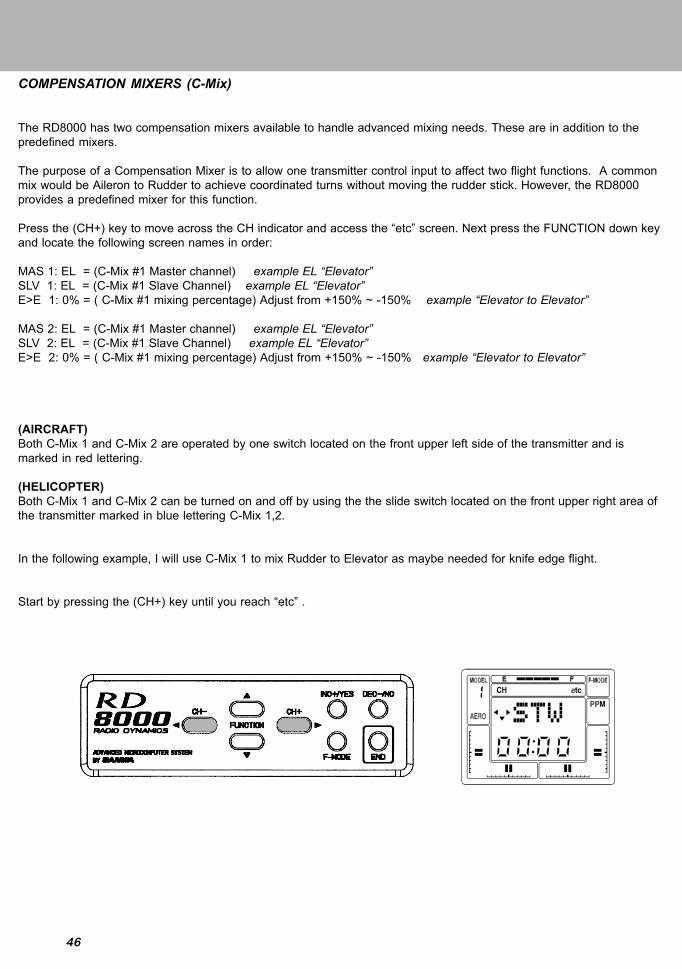
COMPENSATION MIXERS (C-Mix)
The RD8000 has two compensation mixers available to handle advanced mixing needs. These are in addition to thepredefined mixers.
The purpose of a Compensation Mixer is to allow one transmitter control input to affect two flight functions. A commonmix would be Aileron to Rudder to achieve coordinated turns without moving the rudder stick. However, the RD8000provides a predefined mixer for this function.
Press the (CH+) key to move across the CH indicator and access the “etc” screen. Next press the FUNCTION down keyand locate the following screen names in order:
MAS 1: EL = (C-Mix #1 Master channel) example EL “Elevator”SLV 1: EL = (C-Mix #1 Slave Channel) example EL “Elevator”E>E 1: 0% = ( C-Mix #1 mixing percentage) Adjust from +150% ~ -150% example “Elevator to Elevator”
MAS 2: EL = (C-Mix #1 Master channel) example EL “Elevator”SLV 2: EL = (C-Mix #1 Slave Channel) example EL “Elevator”E>E 2: 0% = ( C-Mix #1 mixing percentage) Adjust from +150% ~ -150% example “Elevator to Elevator”
(AIRCRAFT)Both C-Mix 1 and C-Mix 2 are operated by one switch located on the front upper left side of the transmitter and ismarked in red lettering.
(HELICOPTER)Both C-Mix 1 and C-Mix 2 can be turned on and off by using the the slide switch located on the front upper right area ofthe transmitter marked in blue lettering C-Mix 1,2.
In the following example, I will use C-Mix 1 to mix Rudder to Elevator as maybe needed for knife edge flight.
Start by pressing the (CH+) key until you reach “etc” .

47
Now use the FUNCTION down key until you reach the (MAS 1:) screen. Next use the INC or DEC keys untill the RU(rudder) is selected. This will be your Master channel.
Next press the FUNCTION down key once to select (SLV 1:) screen. Now use the INC or DEC keys untill you reach EL(elevator). This will be your Slave channel.
Next press the FUNCTION down key once to select (R>E 1:) screen.By moving the Rudder stick you will see the arrow indicators on the screen change directions acorrding to the directionyou move the stick, left and right. You can set the C-Mix for both directions independantly. For example, when you are ina knife-edge and you give it right rudder but the plane pulls to the top of the aircraft you can simply moved the stick tothe right and press the INC or DEC keys and observe the elevator movment. If by increasing the number moves theelevator in the wrong direction, you can decrease the number into the negative side to change the direction of thecompensation. Only use a small amount of compensation at first. You can set the left compensation in the same manorif any compensation is needed.
When the C-Mix percentages in both directions are at “0”, there will beno compensation mixing.

48
When you use this function you can cause the flaps to deploy when the elevator control stick is moved up or down. Itcan be used with a separete flap servo with an output on the receivers channel #6 or as flaperons with two aileronservos on channel #2 and #6. This function is most commonly used for aerobatic models where deploying flaps (orflaperons), with elevator control can make for tighter corners on maneuvers such as the square loop. In order to use thisfunction with the two aileron servo option you must first active the FLAPERON function. To activate, move the channelselector by pressing the CH+ key until you reach “etc”. Now press the FUNCTION DOWN key several times to reach the“FLAPE” screen and use the YES or No keys to active. Press the END key 2 times to return to the Main screen.
NOTE 1:BASIC must be turned OFF for this feature to operate.
NOTE2: Flap switch must be in the defauft off position “UP”. When activating the FLAPE function, if both servos moveoff center when activating the FLAPE function then move the flap switch down. This will keep the centering of the servoscorrect.
Next press the CH+ key to move to the “EL” indicator. Press the FUNCTION down key until you reach E>F 0% screen.Now you can add elevator to flap amount. Adjustment is from 0~100%.
CAUTION:
Once you activate the E>F mixer by setting in a value, it will be active at all times and the aircraft will respond to allcontrol inputs since you cannot turn it on or off with a switch. You can use a COMPENSATION Mixer feature to be ableto use a switch instead.
ELEVATOR-FLAP MIXING

49
When you use this function you can cause the ailerons to move left and right when the rudder control stick is moved leftor right. The purpose of this mixer is to allow one transmitter control input to affect flight functions. A common usewould be in knife edge flight where you need a small correction in aileron to prevent roll coupleing. To set-up such a mix,use the CH+ key to select RU on the CH indicator.
Next press the FUNCTION down key until you reach R>A 0% screen. Now you can add rudder to aileron mix.Adjustment is from 100~-100%.
You can set both left and right rudder to aileron mix seperatly. By moving the rudder stick you will see the left or rightindicater display on the screen. For example you can set left mix at 20% and right at -30% depending on the directionyou need for the mix.
NOTE 1:BASIC must be turned OFF for this feature to operate.
CAUTION:
Once you activate the R>A mixer by setting in a value, it will be active at all times and the aircraft will respond to allcontrol inputs since you cannot turn it on or off with a switch. You can use a COMPENSATION Mixer feature to be ableto use a switch instead.
RUDDER-AILERON MIXING
RUDDER-ELEVATOR MIXING
Rudder to elevator mixing is used for example when in a knife edge flight, the aircraft pulls to the belly or canopy whenrudder is added.
50
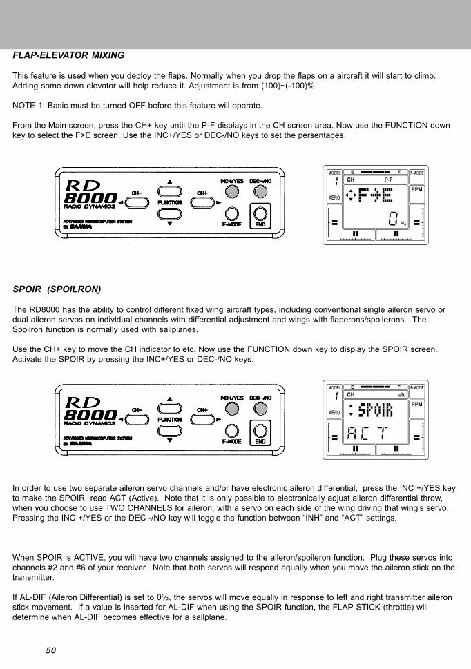
FLAP-ELEVATOR MIXING
This feature is used when you deploy the flaps. Normally when you drop the flaps on a aircraft it will start to climb.Adding some down elevator will help reduce it. Adjustment is from (100)~(-100)%.
NOTE 1: Basic must be turned OFF before this feature will operate.
From the Main screen, press the CH+ key until the P-F displays in the CH screen area. Now use the FUNCTION downkey to select the F>E screen. Use the INC+/YES or DEC-/NO keys to set the persentages.
SPOIR (SPOILRON)
The RD8000 has the ability to control different fixed wing aircraft types, including conventional single aileron servo ordual aileron servos on individual channels with differential adjustment and wings with flaperons/spoilerons. TheSpoilron function is normally used with sailplanes.
Use the CH+ key to move the CH indicator to etc. Now use the FUNCTION down key to display the SPOIR screen.Activate the SPOIR by pressing the INC+/YES or DEC-/NO keys.
In order to use two separate aileron servo channels and/or have electronic aileron differential, press the INC +/YES keyto make the SPOIR read ACT (Active). Note that it is only possible to electronically adjust aileron differential throw,when you choose to use TWO CHANNELS for aileron, with a servo on each side of the wing driving that wing’s servo.Pressing the INC +/YES or the DEC -/NO key will toggle the function between “INH” and “ACT” settings.
When SPOIR is ACTIVE, you will have two channels assigned to the aileron/spoileron function. Plug these servos intochannels #2 and #6 of your receiver. Note that both servos will respond equally when you move the aileron stick on thetransmitter.
If AL-DIF (Aileron Differential) is set to 0%, the servos will move equally in response to left and right transmitter aileronstick movement. If a value is inserted for AL-DIF when using the SPOIR function, the FLAP STICK (throttle) willdetermine when AL-DIF becomes effective for a sailplane.

51
AL-DIF (AILERON DIFFERENTIAL)
The RD8000 has the ability to control several aircraft ‘wing’ types, including conventional single aileron servo, dualaileron servos on individual channels with electronic differential adjustment and delta (or “flying wing”) configurationswith Elevons. It is only possible to electronically adjust differential when using TWO CHANNELS for ailerons, with oneservo on each side of the wing driving that wing’s aileron. The AL-DIF (aileron differential) function only applies to theDELTA and FLAPE menu functions.
Differential refers to the ratio of up-to-down movement of each aileron. Many aircraft need more movement from theupward deflecting aileron than from the downward deflecting aileron in order to eliminate unwanted yaw when aileronsare applied.
Note that differential for the SPOIR (Spoilron) function, that is used with sailplanes, is controlled by the L-DIF (landingdifferential) function. AL-DIF has no effect of SPOIR!
In the following example, we will assume you want to have separate servos for aileron control. Since you must havetwo servos to obtain electronic differential, the first thing to do is activate FLAPE (Flaperons). You now have twochannels assigned to the aileron/flaperon function. Plug these servos into CHANNELS #2 and #6 of your receiver. Notethat both servos will respond equally when you move the transmitter’s aileron control stick. (If you do not want theailerons to act as flaps, select P-H on the Channel indicator, and disable the FLAP switch by setting FLAP EPA to 0%up and down).
Press the FUNCTION down key to select the AL-DIF (aileron differential) screen.
Next, press the INC +/YES key to set a value for aileron differential. In this example the differential is set to 50%. Thismeans that the downward deflecting aileron will move half as much as does the upward-deflecting aileron. The finaladjustments will be determined by actual flight testing.
The above display shows the amount of differential that we have presently programmed. The range of adjustment isfrom –100% to +100%. Default is 0%. If the differential you set is in the wrong direction, i.e., less up-deflection thandown-deflection, change the polarity of the value that you programmed by using the INC +/YES or DEC -/NO keys.

52
L-DIF (LANDING DIFFERENTIAL)
The L-DIF (landing differential) function enables the ailerons of a sailplane to be effective whenever both the left andright ailerons are raised when CROW or SPOIlRON are used in landing. Typical thermal sailplanes require about twiceas much of up travel than down travel of their ailerons in order to produce a coordinated turn. The RD8000 allows you toset the amount of differential aileron travel during the landing mode. To use L-DIF the SPOIR (Spoilron) function mustbe set to Active. See page 50 and activate the SPOIR function.
Next, press the FUNCTION down key to scroll to the L-DIF (landing differential) screen.
Now, press the DEC -/NO key to set a value of –50% for L-DIF.
Note that the application of Landing Differential is controlled by the position of the FLAP (throttle) stick. As you bringthe stick down and deploy your flaps, the aileron landing differential increases to the amount that you programmed. Inthe above example we set L-DIF to –50%. However, the polarity of the setting depends on your specific aircraft’s servoinstallation, i.e., the setting can either be positive or negative.
Move your aileron stick from side to side and observe the change in the ratio of up to down travel as you bring the FLAPstick down.
The range of adjustment of L-DIF is from –100% to +100%. To reset L-DIF to the default value of 0%, press both theINC +/YES and DEC -/NO keys simultaneously.
Flight testing will be required to determine the optimum setting for your L-DIF.

53
CR:LA (CROW LEFT AILERON)CR:RA (CROW RIGHT AILERON)
In a sailplanes landing mode, the flaps provide a large amount of both lift and drag. This causes the plane to fly veryslowly and descend gently. On very light sailplanes the rate of descent may be so slow that the plane tends to “floatright past” the landing spot. CROW (both ailerons up) adds quite a bit of drag while decreasing lift. This increases therate of descent (steepens the glide slope) and improves controllability. The amount of CROW that is used should beadjusted to suit personal preference. In general, higher wing loading sailplanes require less CROW because the rate ofdescent will probably already be high enough.
In order to program the CROW function you must have previously selected the SPOIR(Spoilron) function and set it toActive.
Press the FUNCTION down key to select the CR:LA (Crow left aileron) screen.
Next, press the INC +/YES key to program a value of 25%. Here we have set CROW for the Left Aileron at 25%. TheLeft Aileron now will raise 25% of its travel upwards while the flaps deploy downwards while in the Landing Mode. TheLanding Mode, Flap deployment and CROW are all controlled by the position of the FLAP (throttle) stick. The range ofadjustment for CROW is from +100% to –100%. The default value is 0%.
Now, press the FUNCTION down key to move down to the CR:RA (CROW right aileron) screen. Press the INC +/YESkey to set it at 25%. Now both ailerons respond identically to the CROW command.

54
OPTION MENU SCREEN
In the advanced programming you have the ability to turn off unused programming screens with the OPTION MENUSCREEN. This is vary useful and vary convenient when one of your models only requires some features. For exampleone aircraft is used as a triainer and you do not need to use any C-MIX, CROW, AI-DIF, DELTA, V-TAIL, you can go tothe OPT screen and turn them off so they will not display in the normal programming screens. If you decide later thatyou want to use a feature you have turned off, you can at anytime use the OPT to turn the feature back on.
NOTE 1: Turning off the feature only removes it from the programming screen. It will not however turn off thefeature. Example, you had activated your FLAPE for Flaperons and then in the OPT screen you turnedFLAPE off. Your Flaperons will still be active but you will not see the FLAPE screen in the programmingmenu.
NOTE 2: This feature is best used on an aircraft or helicopter after you have setup your “need on all the time” features.For example the swash plate type for a helicopter, once you select the swash plate type you can then turn theswash plate type screen off because you have no adjustments in that screen and by turning the screen offyou will not mistakenly change the swash plate type.
Before turning off any unused feature screens, make sure they are at there default setting or do not have any affect onany control surface.
Use the CH+ key to move to the etc in the CH area of the main screen. Next use the FUNCTION down key until youreach the OPT screen. Now press the YES key, the OPT will now flash 3 times. Now you can use the FUNCTION downkey to view all the feature screens that can be turned off. Turning the feature on or off is done by using the YES or NOkeys. After selecting YES or NO, you can now press the END key to exit out of the OPT screen. Pressing END 3 timeswill bring you to the main screen.

55
STEP (TRIM STEP)
Any trim that you set while your model is in flight by use of the Digital Trim keys will automatically be stored in memoryfor that specific channel and model; providing that TRM was previously turned OFF in the OPTIONS section of theprogram.
The Trim value in % that you set during flight is shown on the TRM screen for each Channel. In addition, there are bargraph indicators on the screen at all times that visually show how much trim has been set for Elevator, Aileron, Throttleand Rudder channels.
The amount that the Trim Function changes every time you press the Digital Trim key i.e., the Trim Authority, isvariable, and it can be set by the user. For initial test flights of your model it is recommended that it be set at a value of7 to allow for maximum ability to trim your model. After your first flight and your aircraft has been trimmed, you canthen program a more precise adjustment for trim authority by use of the STEP function.
To change the Trim Authority, access the STW screen for EL as previously explained. Press the CH + key several timesto select the “etc” screen. Now press the FUNCTION down key until you find the following screen that indicates STEP.
If you want to change the Trim Authority to a lesser number to make the Digital Trim keys less sensitive for a finersetting, press the DEC -/NO key. If you want to increase the sensitivity to obtain a greater change, press the INC +/YES key. The maximum value of Trim Authority is 15 and the minimum value is 0. CAUTION: If set to zero, you donot have any Trim capability.

56
FAIL (FAIL SAFE)
The RD8000 transmitter provides the capability to program Fail Safe for all six channels. However, Fail Safe is ONLYavailable when you are using a PCM receiver and transmitting in the PCM 1 or PCM 2 Modulation mode. If you aretransmitting PPM/FM or PPM/FM-Reverse, you will not be able to enable the FAIL SAFE function.
The Airtronics PCM receivers have the capability to be programmed to respond to RF signal interference bymomentarily holding the last known good command. If the interference lasts longer than one second, then thereceiver’s microprocessor will drive the servos to the preprogrammed positions you previously set-up using the FAIL (failsafe) function.
To program Fail Safe, you first must select PCM 1 or PCM 2 Modulation for your specific type of receiver.
For example, if you want to set up elevator to occur if interference causes loss of signal at your receiver, select the EL(elevator) channel on the Channel indicator.
Next, press the FUNCTION down key to access the FAIL screen.
Now position your elevator stick in a slightly up position that you want for the Fail Safe position. Press the INC +/YESkey to set the position that the elevator servo will be set to upon loss of signal.
To test the action of your preprogrammed Fail Safe, place your elevator stick in the neutral position. Then turn Off yourtransmitter power switch. Your elevator servo will go to the fail safe position that you previously programmed. To returnto the INHIBIT condition, press the INC +/YES and the DEC -/NO keys simultaneously.
The same procedure as indicated above applies to setting the Fail Safe positions for the other channels. For example, ifyou want to have a small amount of throttle applied during Fail Safe, first select the throttle channel on the Channelindicator. Then scroll down to the TH Fail Safe screen. Hold a small amount of throttle and press the INC +/YES key toprogram the amount of throttle you want for Fail Safe. Test by turning Off your transmiter switch.
NOTE: If interference is present when Fail Safe is not active, in PCM Modulation, the receiver will “hold” the lastcommand received until the signal is again established.

57
B-F-S (BATTERY FAIL SAFE)
Your RD8000 offers a Fail Safe function to warn you of a low voltage condition in your receiver’s battery pack. Thisfunction is only operable when using the AIRTRONICS PCM receivers.
You first must select either PCM 1 or PCM 2 modulation.
To activate the Battery Fail Safe program, select “etc” on the Channel indicator by using either the (CH –) or the(CH +) keys. (Note that you must be on the STW screen to be able to move horizontally across the screen to “etc”.)
Press the FUNCTION down key to select the B-F-S (battery fail safe) screen.
Next, press the Inc +/YES key to change the B-F-S to “ACT”, indicating that the Battery Fail Safe function is now active.(pressing either the INC +/YES or the DEC -/NO key will toggle the function between “INH” and “ACT” settings.)
When the B-F-S is set to “ACT”, the PCM receiver will monitor the receiver pack voltage to warn you when it reaches thetarget level, approximately 4.7 volts. When the airborne battery is at this point, the throttle servo will move to a lowthrottle position for one second, and then return to normal. This cycling of the throttle servo will occur about once eachminute until you land and recharge the NiCd battery pack. IT IS RECOMMENDED THAT YOU LAND IMMEDIATELY ifthe receiver fail safe warns you of low voltage conditions!
Press the END key to return to the STW screen.
BASIC MENU
By default the BASIC aircraft and helicopter programming menu are on. Basic programming gives you the basicfeatures included in the RD8000. By turning BASIC OFF, you are turning on the ADVANCED aircraft or helicopterprogramming menu.
To turn BASIC OFF, press the CH+ key until you reach “etc” in the CH area on the main screen. Now press theFUNCTION down key untill you reach the BASIC ON screen. Press the YES or NO key to turn on the Advancedprogramming menu. Press the END key 2 times to return to the main screen.

58
DUAL ELEVATOR MIXING
Your RD8000 offers a feature that will allow you to use 2 independent channels so you can use 2 seprate servos foreach elevator half. You will be using Channels 1 and 7 on the receiver to use this feature.
Activating the Daul Elevator feature will automaticly disable your AUX-1 channel 7 switch and will allow channel 7 to beused with the elevator stick.
You will be able to set the EPA, REV, CENTER and FAIL safe seperatly for both channels. Use Channel 1 for your leftelevator and use channel 7 for your right elevator.

59
RD8000 Transmitter - HELICOPTER
Gyro
Trainer Switch
Throttle (U/DRudder (L/R)
Throttle Digital Trim
Rudder Digital Trim
Panel Input Keys
Flight Mode 3
(See Page 73 tochange F.M. switchlocations)
Digital Hover Throttle INC / DEC
AUX 2
C-Mix 1, 2
Throttle Cut Switch
Elevator (U/D)Aileron (L/R)
Elevator Digital Trim
Aileron Digital Trim
Main Power Switch
Flight Mode N,1,2
(See Page 73 tochange F.M. switch
locations)
92778Z Receiver Channel Assignments
Receiver Plug Number12345678
Plug in Servo For:Elevator (F/A) CyclicAileron (L/R) CyclicThrottleRudder (Tail Rotor)GyroCollective PitchAUX 1AUX 2 / Battery
Liquid Crystal Display
Digital Hover Pitch INC / DEC
AUX 1
Flight Mode Selector

60
HELICOPTER BASIC MENU STRUCTURE
(Rx Channel) CH EL AL TH RU G P/F 7 8 etcSTW STW STW STW STW STW STW STW STWREV REV REV REV REV REV REV REV M-SLD/R D/R CNT D/R GYR CNT CNT CNT TYPCNT CNT EPA CNT EPA EPA EPA RSTEPA EPA CV-PH EPA CV-PH BASIC ON
CV-P3 RV.H CV-P3CV-P2 RV.M CV-P2CV-P1 RV.L CV-P1CV-PL CV-PL
NOTE: Use the (CH-) and (CH+) keys to move horizontally within the same function.Use the FUNCTION UP and FUNCTION DOWN keys to move vertically within the menu.The small trianges to the left of the function that shows on the LCD screen indicates the direction that you can movehorizontally and vertically in the menu.
Use the four center buttons in the function panel to navigate throught the menu’s. (UP / DOWN / LEFT / RIGHT)
(Rx Channel) CH EL AL TH RU G P/F 7 8 etcSTW STW STW STW STW STW STW STW STWTRM TRM TRM TRM REV REV REV REV M-SLREV REV REV REV GYR CNT CNT CNT NAMD/R D/R CNT D/R FAIL EPA EPA EPA MAS 1EXP EXP EPA EXP CV-PH FAIL FAIL SLV 1CNT CNT CV-PH CNT CV-P3 E>E 1EPA EPA CV-P3 EPA CV-P2 MAS 2FAIL FAIL CV-P2 RV-H CV-P1 SLV 2
CV-P1 RV-M CV-PL E>E 2CV-PL RV-L FAIL STW setT-CUT FAIL INT setFAIL STEP
TYP SW-R CPY RST MOD CLK B-F-S DTM SWH BASIC OFF OPT
HELICOPTER ADVANCED MENU STRUCTURE

61
PROGRAMMING FOR HELICOPTER
INITIAL SET-UP OF TYP (MODEL TYPE)
When you receive your RD8000 unit the transmitter is preprogrammed for both fixed wing aircraft model’s as well as forhelicopter models. If you fly only helicopter model aircraft, you can change model’s 1,3,5,7 and 9 to helicopter.
Turn the transmitter power ON and press the END key until you come to the default main screen. The inital screen willshow AR1 which indicates the aircraft type as well as showing the NiCd battery voltage.
Press the (CH+) key to scroll across the CH (channel) indicator on the screen to “etc”.
Press the FUNCTION down Key once to access the TYP (model type) screen.

62
Note that one of the small triangular indicators will be blinking to show that you should press the (CH+) key. Therefore,press the (CH+) key and the screen will change to read HELI with a flashing YES.
To confirm the change of aircraft type, press the INC+/YES key. The screen will then change to read OK! As shown onscreen below to indicate the model type has been changed to HELI from model #1. Press the END key twice to return tothe STW screen.
Press the END key twice to return to the STW screen. The same procedure as noted above can be used to changeModel #3, 5, 7, 9 from AERO to HELI.

63
PITCH CURVES (FLIGHT MODES)
The RD8000 allows you to customize four distinct flight modes for each helicopter model.
The four pitch curves (flight modes) available for each helicopter model are:
N…………………………..Select Curve N -- NORMAL1…………………………...Select Curve One – IDLE UP 12…………………………...Select Curve Two – IDLE UP 23........................................Select Curve Three -- HOLD
Selecting a pitch curve is done by activating the two FLIGHT MODE switches located on the top of the transmitter asshown below. The default positions are as indicted.
Note that BOTH F-MODE switches must be positioned towards you to select F-MODE NORMAL.
CAUTION: Flight Modes 1, 2 and 3. If either one is activated when you turn on the transmitter, an audio alarm willsound. You must always be aware of which flight mode you have selected before starting your engine or attemptingflight!
NOTE: See page 73 on how to reverse the 2 position and three position switchs. Normal heli flying in the U.S. have thethree position switch on the left side of the transmitter.
F-Mode 3 or Hold:Switch positionedaway from you
F-Mode Normal: Switch positionedtowards you
F-Mode 2:Switch positioned
away from you
F-Mode 1:Switch positioned in
center
F-Mode Normal:Switch positioned
towards you

64
The pitch curve for each flight mode has five points that can be adjusted to suit your specific needs. Within each pitchcurve these points are referred to as PH (high pitch), P3, P2, P1 and PL (low pitch). The range of values and defaultsettings for each is shown below. To activate P3 and P1, press the YES key when in P3 or P1 screens. To set back todefault, press both the YES and NO keys at the same time.
FLIGHT MODE Curve Point Minimum Default Maximum
Normal PH -25% 100% 125%P3 -25% INH 125%P2 -25% 50% 125%P1 -25% INH 125%PL -25% 0% 125%
F. Mode 1 and 2 PH -25% 100% 125%P3 -25% INH% 125%P2 -25% 50% 125%P1 -25% INH 125%PL -25% 0% 125%
F. Mode 3 or Hold PH -25% 0% 125%P3 -25% INH 125%P2 -25% 0% 125%P1 -25% INH 125%PL -25% 0% 125%
To program your pitch curves, press the (CH –) or (CH +) key to select P-F on the Channel indicator.
Next, press the FUNCTION down key and scroll down to the CV-PH screen.
Press the F-MODE (flight mode) switch to toggle through modes 1, 2, 3 and Normal.

65
Now use the F-MODE switch to select the specific flight mode that you want to adjust. As an example, if you wanted toadjust CV-P2 in Normal flight mode, press the FUNCTION down key to select CV-P2. The default value for the Normalflight mode of 55% will be shown.
Press the INC+/YES key to set an increase in value or press the DEC-/NO key to set a lesser value. Press both INC+/YES and DEC-/NO keys simultaneously to return to the default value.
Fine tuning of the Hover Pitch is also available by use of the HOV-PT digital trim switch located above the throttle stick.NOTE: HOV-PI and HOV-TH trims are used only for adjustment in flight mode N (normal). They have no affect on FlightMode 1 or 2.
In normal operation you will usually set the approximate Hovering Pitch with the software in the Pitch screens thenadjust as needed for various weather and flying conditions with the HOV-PI (hover pitch) digital trim switch.
HOV-TH + -Digital Trim
HOV-PI + -Digital Trim

66
THROTTLE CURVES (FLIGHT MODES)
The throttle curve for each flight mode has five points that can be adjusted to suit your specific needs. Within eachthrottle curve these points are referred to as PH (high pitch) P3, P2, P1 and PL (low pitch). The range of values anddefault settings for each is shown below. To activate P3 and P1, press the YES key when in P3 or P1 screens. To setback to default, press both the YES and NO keys at the same time.
FLIGHT MODE Curve Point Minimum Default Maximum
Normal PH -25% 100% 125%P3 -25% INH 125%P2 -25% 50% 125%P1 -25% INH 125%PL -25% 0% 125%
F. Mode 1and 2 PH -25% 100% 125%P3 -25% INH 125%P2 -25% 50% 125%P1 -25% INH 125%PL -25% 0% 125%
F. Mode 3 or Hold PH -25% 0% 125%P3 -25% INH 125%P2 -25% 0% 125%P1 -25% INH 125%PL -25% 0% 125%
To program your throttle curves, press the (CH –) or (CH +) key to select P-F on the Channel indicator.
Next, press the FUNCTION down key and scroll down to the CV-PH screen.

67
Now use the F-MODE switch to select the specific flight mode that you want to adjust. As an example, if you wanted toadjust CV-P2 in Normal flight mode, press the FUNCTION down key to select CV-P2. The default value for the Normalflight mode of 50% will be shown.
Press the INC+/YES key to set an increase in value or press the DEC-/NO key to set a lesser value. Press both INC+/YES and DEC-/NO keys simultaneously to return to the default value.
Fine tuning of the Hover Throttle is also available by use of the HOV-TH digital trim switch located above the elevatorstick.
Press the F-MODE (flight mode) switch to toggle through modes 1, 2, 3 and Normal.

68
REVOLUTION MIXING
The RD8000 provides for setting Revolution Mixing for each of the four Flight Modes. Each Flight Mode has its owncurve for adjusting tail rotor position in response to the throttle/collective stick movements. The default settings for RV.H(Revolution Mixing High Point), RV.M (Revolution Mixing Mid Point), and RV.L (Revolution Mixing Low Point) are asfollows:
FLIGHT MODE RV.H RV.M RV.L
Normal 20% 0% -20%F. Mode #1 0% -2% -5%F.Mode #2 0% -5% -10%F.Mode #3 0% 0% 0%
To program Revolution Mixing, press either the (CH –) or (CH +) key to select RU ( rudder) on the Channel indicator.
Next, press the FUNCTION down key to select RV.H which is the revolution mixing high point.
Use the INC +/YES or DEC -/NO key to change the default value if you desire to do so for any of the three flight modes.In this example we have set RV.H for the Normal flight mode to + 25%.
The same procedure can be used to input values for RV.M and RV.L. Press the Flight Mode switch to select the differentFlight Modes.

69
GYRO ADJUSTMENT
The RD8000 allows you to set the Gyro sensitivity of your helicopter’s gyro if it has that capability. The gain of the gyrocan be adjusted for all of the four Flight Modes and have 2 settings for each. In this manner the pilot can adjust thegyro for a suitable level of sensitivity (gain) for one flight mode (for instance hover), and by changing to a different flightmode alter the sensitivity for either more or less stabilization. Note that you must be using a gyro that offers remotesensitivity adjustment.
Press either the (CH –) or the (CH +) key to select G (Gyro) on the Channel indicator.
Now, press the FUNCTION down key several times to access the GYR (gyro) screen. The display will look like thefollowing screen when the Normal flight mode is selected.
To adjust the gyro sensitivity for a specific flight mode, press either the INC +/YES or DEC- /NO key. Default values are: Normal 100%, F.Mode #1 50%, F.Mode #2 60% and F.Mode #3 100%. The range of adjustment is from – 150% to +150%. Press the Flight Mode switch to change from one flight mode to another.
Fine tuning of your gyro sensitivity for the various flight modes can be accomplished by flight tests.
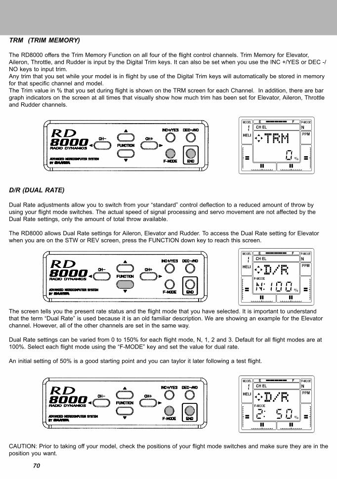
70
TRM (TRIM MEMORY)
The RD8000 offers the Trim Memory Function on all four of the flight control channels. Trim Memory for Elevator,Aileron, Throttle, and Rudder is input by the Digital Trim keys. It can also be set when you use the INC +/YES or DEC -/NO keys to input trim.Any trim that you set while your model is in flight by use of the Digital Trim keys will automatically be stored in memoryfor that specific channel and model.The Trim value in % that you set during flight is shown on the TRM screen for each Channel. In addition, there are bargraph indicators on the screen at all times that visually show how much trim has been set for Elevator, Aileron, Throttleand Rudder channels.
D/R (DUAL RATE)
Dual Rate adjustments allow you to switch from your “standard” control deflection to a reduced amount of throw byusing your flight mode switches. The actual speed of signal processing and servo movement are not affected by theDual Rate settings, only the amount of total throw available.
The RD8000 allows Dual Rate settings for Aileron, Elevator and Rudder. To access the Dual Rate setting for Elevatorwhen you are on the STW or REV screen, press the FUNCTION down key to reach this screen.
The screen tells you the present rate status and the flight mode that you have selected. It is important to understandthat the term “Dual Rate” is used because it is an old familiar description. We are showing an example for the Elevatorchannel. However, all of the other channels are set in the same way.
Dual Rate settings can be varied from 0 to 150% for each flight mode, N, 1, 2 and 3. Default for all flight modes are at100%. Select each flight mode using the “F-MODE” key and set the value for dual rate.
An initial setting of 50% is a good starting point and you can taylor it later following a test flight.
CAUTION: Prior to taking off your model, check the positions of your flight mode switches and make sure they are in theposition you want.

71
DTM (DYNAMIC TRIM MEMORY)
Dynamic Trim Memory (DTM) is an advanced function that can be used in conjunction with the Flight Mode OPTIONS.When activated Dynamic Trim Memory allows you to make trim changes while in any flight mode WITHOUT affectingany other flight mode or model.
Flight Modes are used to allow activation of the DTM function. The four flight modes are:
NORMALF.M. #1………….IDLE-UP 1F.M. #2………….IDLE-UP 2F.M. #3...............THOTTLE HOLD
Activating DTM will allow trim changes made in one flight mode to affect ONLY that specific mode. To activate DynamicTrim Memory, press the (CH +) or the (CH –) key to select “etc” on the Channel indicator.
Now, press the FUNCTION down key to scroll down the menu to the DTM screen.
Press the INC +/YES or the DEC -/NO key to change DTM to ACT (active). Pressing either key will toggle the indicationfrom ACT to INH. Press the END key to return to the STW screen.
Once activated, the Dynamic Trim Memory function is transparent to the pilot. Simply activate a Flight Mode, (forinstance “Normal”) and trim the aircraft for stable hover using the digital trim keys. Then, switch to another flight mode,and do the same as desired. Note that when you change flight modes, the servos affected by the DTM function willreturn to the original neutral position regardless of the value of trim set-in for the previous flight mode. However, thethrottle channel is an exception to the rule. The trim that is set for one flight mode will affect all other flight modes.Also be aware that the throttle trim key only affects the low throttle position of the throttle servo. Throttle trim DOESNOT affect the collective pitch servo.

72
SWH (SWASH PLATE TYPE)
Your RD8000 allows you to select the SWH (Swash) mode of operating the main rotor pitch which is controlled by theSwash Plate moving up or down. When the Swash Mode is selected, the outputs of the Elevator, Aileron and Pitchservos are mixed to control the pitch of the helicopters main rotor. Cyclic, Collective, Pitch Mixing (CCPM) can only beused on a helicopter that is designed for CCPM. The servos are mounted on the side frames directly under the SwashPlate with a direct linkage connection from the servo arm to the Swash Plate. This installation is designed to eliminateany slop that can occur with multiple linkages and levers. The three servos are mixed in various ways to obtain thecontrol response that is needed for Aileron, Elevator and Pitch control.
The RD8000 can control the following types:
NOR Normal type. The elevator, aileron and pitch servos are independent of each other on the receiver channls.
CP3F Three joint balls are located in a triangle. The Elev ball is located in front.
CP3B Same as CP3F but Elevator ball is located in the rear or back.
CP4F The Elevator ball joint is located at 90 degress from the Aileron ball joint. The Elevator ball joint is located inthe front.
CP4B The same as CP4F except the Elevator ball is located in the rear or back.
The following drawings illustrate the various types of CCPM available with the RD8000.

73
CHANEGING FLIGHT MODE 1 and 2 Switch Locations
From the factory flight mode 1 switch is on the right top toggle and flight mode 2 is on the left top toggle switch. Somefliers perfer having flight mode 1 switch on the left top and flight mode 2 on the right top switch. The following will behow to change flight mode 1 and 2 switch locations.
1 Remove the NiCd battery cover and NiCd battery pack.2 Remove the antenna by unscerwing it counter clockwise.3 Remove all 8 scerws located on the back of the transmitter. Refer to page 11 for screw locations.4 Remove both left and right switch retainer nuts located on top of the switches.5 Cut both left and right wire tie’s holding the wiring to both switches.6 With a black marker pin put a dot on the plastic base of the switch to indicate the rear of the switch. This will
help to not mistakenly flip the switch over.7 Remove both switches by sliding them down into the transmitter case and change the locations.8 Reinstall both switch retainer nuts and secure in place.9 Arrange both switch wires away from any moving parts and secure with new wire tie’s making sure the wires
will not get in the way of the antenna as it is being reinstalled.10 Reinstall the transmitter rear case and be careful when placing it over the NiCd battery connector pins.11 Reinstall all 8 case scerws.12 Reinstall Antenna by screwing clockwise.13 Reinstall the NiCd battery and battery Cover.
Before After
Wire Tie locations Wire Tie locationsAfter you have completed the switching over of both flight mode 1 and 2 switches, you can now replace the two frontswitch identifying labels. (new labels are supplied)
Use a small scerw driver to pry up the old label to remove. Be carfull not to damage the plastic transmitter case. Nextpeel the backing off the new label and secure in place.
New switch location labels
WARNING:Any other modifications made to the transmitter other than changing the flight mode switch locations will void any andall warranties covered by Airtronics Inc.

74
RD8000 / TYPE: AERO MODULATION PPM / PPM-R / PCM1 / PCM2
MODEL #........................................................................MODEL NAME....................................................
WING TYPE NORMAL DELTA V-TAIL FLAPERON
FLAPERON & V-TAIL
CH (1) EL (2) AL (3) TH (4) RU (5) G (6) F
TRM
REV NOR / REV
% % % % %
NOR / REV NOR / REV NOR / REV NOR / REV NOR / REV
D/R
EXP
CNT
EPA
1
2
1
2
%
%
%
%
%
%
%
%
% % % % %
UP LT HI LT HI
DN RT LO RT LO
%
%
%
%
%
%
%
%
%
%%
MIX A > R T > E%
%
SPOIRON (GLID) SPOIRON & V-TAIL (GLID)
FAIL% % % % % %
E > F R > ER > A F > E
% % %
%
%
%
%

75
C-MIX T-CUT
TRM
REV
%
%
1
2
MAS SLA VALUE
%
%
%
STW :
STEP
%
SWR-R NOR / REV
%
INH / ACTB-F-S
AI-DIF
L-DIF%
CR:LA
CR:RA
%
D/R-A
BASIC
INH / ACT
ON / OFF
TRMREVD/REXPCNTEPAE>FA>RR>AT>ER>EF>ET-CUTFAILNAMC-MIX1C-MIX2STWINTSTEPTYPSW-RCPYRSTMODCLKB-F-SFLAPESPOIRDELTAV-TAILAI-DIFL-DIFCR:LACR:RAD/R-A
OPT ON ALL ONOFF
RD8000 / TYPE: AERO MODULATION PPM / PPM-R / PCM1 / PCM2
MODEL #........................................................................MODEL NAME....................................................

76
CH (1) EL (2) AL (3) TH (4) RU (5) GY (6) PI
TRM
REV NOR / REV
%
NOR / REV NOR / REV NOR / REV NOR / REV NOR / REV
D/R
EXP
CNT
EPA
N
2
%
%%
%
%
%%
%
% %
UP LT HI LT
DN RT LO RT
%
%
%
%
%
%
%
%
%%
N
1
2
DTMACT %
%
%
%
%
% %
% % %% %
HI
LO
N
1
2
%
%
%
%%
TH-CV PL P1 P2
N1
2
% % %
% % %
% % %
SWASH TYPE NORMAL CP3F CP3B CP4F CP4B
3 (HOLD)
% % %
1
HN
2 1
H % %% %
%
%%
%
%%
%%
H %FAIL % % % % % %
3 (HOLD)
% %
% %
% %
% % % % %
PHP3
RD8000 / TYPE: HELI MODULATION PPM / PPM-R / PCM1 / PCM2
MODEL #........................................................................MODEL NAME....................................................

77
RD8000 / TYPE: HELI
MODEL #........................................................................MODEL NAME....................................................
T-CUTRV PL P2 PH
N1
2
% % %
% % %
% % %
C-MIX MAS SLA VALUE
1
2
%
%
%
%
STW :
STEP NOR/ REV
SW-R NOR/REV
PI-CV PL P1 P2
N1
2
% % %
% % %
% % %
3 (HOLD)
% %
% %
% %
% % % % %
PHP3
% % %3 (HOLD)
%B-F-S
DTM
HOLD INH / ACT
BASIC ON / OFF
INH / ACT
INH / ACT
TRMREVD/REXPCNTEPATH-CPI-CT-CUTRVLFAILNAMC-M1C-M2STWINTSTEPTYPSW-RCPYRSTMODCLKB-F-SDTMSWHALL
ALL ONOPT ON OFF
MODULATION PPM / PPM-R / PCM1 / PCM2