Embed Size (px)
Citation preview

DRAFT SOUTH AFRICAN STANDARD (DSS):
PUBLIC ENQUIRY STAGE
Document number SANS 10287ED2
Reference SABS/TC 021/SC 01/SANS 10287
Date of circulation 25 March 2021
Closing date 25 May 2021
Number, edition and title: SANS 10287ED2: Automatic sprinkler installations for fire-fighting purposes
Remarks:
PLEASE NOTE:
The technical committee, SABS/TC 21/SC01; Fire Safety - Fixed Fire Detection and Extinguishing Systems
responsible for the preparation of this standard has reached consensus that the attached document
should become a South African standard. It is now made available by way of public enquiry to all interested
and affected parties for public comment, and to the technical committee members for record purposes.
Any comments should be sent by the indicated closing date, either by mail, or by fax, or by e-mail to
SABS Standards Division
Attention: Compliance and Development department
Private Bag X191
Pretoria
0001
Fax No.: (012) 344-1568 (for attention: dsscomments)
E-mail: [email protected]
Please use the SABS Commenting template to submit comments.
Please click on this link DSS_COMMENTING_TEMPLATE to download the template. For instructions to
complete the commenting template please click on SABS Template for comments and secretariat observations
- User Guide for the user guide
Any comment on the draft must contain the number of the clause/sub clause to which it refers. A comment
shall be well motivated and, where applicable, contain the proposed amended text.
The public enquiry stage will be repeated if the technical committee agrees to significant technical
changes to the document as a result of public comment. Less urgent technical comments will be
considered at the time of the next amendment.
THIS DOCUMENT IS A DRAFT CIRCULATED FOR PUBLIC COMMENT. IT MAY NOT BE REFERRED TO AS A
SOUTH AFRICAN STANDARD UNTIL PUBLISHED AS SUCH.
IN ADDITION TO THEIR EVALUATION AS BEING ACCEPTABLE FOR INDUSTRIAL, TECHNOLOGICAL,
COMMERCIAL AND USER PURPOSES, DRAFT SOUTH AFRICAN STANDARDS MAY ON OCCASION HAVE TO BE
CONSIDERED IN THE LIGHT OF THEIR POTENTIAL TO BECOME STANDARDS TO WHICH REFERENCE MAY BE
MADE IN LAW.
AZ96.10 2020/03/01 sabs pta
This Draft South African Standard (DSS) is exclusively for use on the local drive of your Personal Computer with access only for your personal use. The
standard may only be used for commenting purposes to facilitate the standards development process. This standards may not be resold.
Draft S
A Stan
dard

ISBN 0-626- SANS 10287:XXXX
Edition 2
SOUTH AFRICAN NATIONAL STANDARD
Automatic sprinkler installations for fire-fighting purposes
WARNING This document references other
documents normatively.
Published by the South African Bureau of Standards 1 Dr Lategan Road Groenkloof Private Bag X191 Pretoria 0001 Tel: +27 12 428 7911 Fax: +27 12 344 1568 www.sabs.co.za
SABS
This Draft South African Standard (DSS) is exclusively for use on the local drive of your Personal Computer with access only for your personal use. The
standard may only be used for commenting purposes to facilitate the standards development process. This standards may not be resold.
Draft S
A Stan
dard

This page has been left blank intentionally
This Draft South African Standard (DSS) is exclusively for use on the local drive of your Personal Computer with access only for your personal use. The
standard may only be used for commenting purposes to facilitate the standards development process. This standards may not be resold.
Draft S
A Stan
dard

COPYRIGHT PROTECTED DOCUMENT
© SABS
In terms of the Standards Act 8 of 2008, the copyright in all South African National Standards or any other publications published by the SABS Standards Division, vests in the SABS. Any use of South African National Standards is limited to use specifically prescribed by the SABS. In the case of a South African National Standard based on an international standard, ownership of the copyright vests in the organization from which the SABS adopted the standard, whether it be under licence or membership agreement. The SABS is obliged to protect such copyright and is authorized to make the relevant international organization aware of any misuse thereof. Unless exemption has been granted, no extract or full text of any South African National Standard may be copied, reproduced, stored in a retrieval system or transmitted in any form or by any means without prior written permission from the SABS Standards Division. This does not preclude the free use, in the course of implementing the standard, of necessary details such as symbols, and size, type or grade designations. If these details are to be used for any purpose other than implementation, prior written permission must be obtained.
Details, advice and limitations of use can be obtained from the Manager: Standards Sales and Information Services. Tel: +27 (0) 12 428 6883 email: [email protected] SABS – Standards Division
The objective of the SABS Standards Division is to develop, promote and maintain South African National Standards. This objective is incorporated in the Standards Act, 2008 (Act No. 8 of 2008).
The SABS continuously strives to improve the quality of its products and services and would therefore be grateful if anyone finding an inaccuracy or ambiguity while using this standard would inform the secretary of the technical committee responsible, the identity of which can be found in the foreword.
Buying Standards
Contact the Sales Office for South African and international standards, which are available in both electronic and hard copy format. Tel: +27 (0) 12 428 6883 email: [email protected] South African National Standards are also available online from the SABS Webstore www.store.sabs.co.za Information on Standards
SABS Customer Services provide comprehensive standards-related information on national, regional and international standards. Tel: +27 (0) 12 428 7911 / 0861 27 7227 email: [email protected]
This Draft South African Standard (DSS) is exclusively for use on the local drive of your Personal Computer with access only for your personal use. The
standard may only be used for commenting purposes to facilitate the standards development process. This standards may not be resold.
Draft S
A Stan
dard

SANS 10287:XXXX Edition 2
Table of changes
Change No. Date Scope
Foreword This South African standard was prepared by National Committee SABS/TC 021/SC 01, Fire safety – Fixed fire detection and extinguishing systems, in accordance with procedures of the South African Bureau of Standards, in compliance with annex 3 of the WTO/TBT agreement. This document was approved for publication in xxxxx 20XX. This document supersedes SABS 0287:2000 (edition 1). Reference is made in 3.1.17 to the "relevant national legislation". In South Africa this means the National Building Regulations and Building Standards Act, 1977 (Act No. 103 of 1977). Compliance with this document cannot confer immunity from legal obligations.
Introduction An automatic sprinkler system is designed to detect a fire and extinguish it with water in its early stages or hold the fire in check so that extinction can be completed by other means. A sprinkler system consists of a water supply (or supplies) and one or more sprinkler installations. Each installation consists of a set of installation main control valves and a pipe array fitted with sprinkler heads. The sprinkler heads are fitted at specified locations at the roof or ceiling, and where necessary between racks, below shelves, and any other location as recommended in this document. The sprinklers operate at predetermined temperatures to discharge water over the affected part of the area below. The flow of water through the alarm valve initiates a fire alarm. The operating temperature is generally selected to suit ambient temperature conditions. Only sprinklers in the vicinity of the fire, i.e. those which become sufficiently heated, operate. The sprinkler system is intended to extend throughout the premises with only limited exceptions. It should also not be assumed that the provision of a sprinkler system entirely obviates the need for other means of fighting fires and it is important to consider the fire precautions in the premises as a whole. Structural fire resistance, escape routes, fire alarm systems, particular hazards needing other fire protection methods, provision of hose reels and fire hydrants and portable fire extinguishers, safe working and goods handling methods, management supervision and good housekeeping all need consideration.
© SABS
This Draft South African Standard (DSS) is exclusively for use on the local drive of your Personal Computer with access only for your personal use. The
standard may only be used for commenting purposes to facilitate the standards development process. This standards may not be resold.
Draft S
A Stan
dard

SANS 10287:XXXX Edition 2
1
Introduction (concluded)
It is essential that sprinkler systems should be properly maintained to ensure operation when required. This routine is liable to be overlooked or given insufficient attention by supervisors. It is, however, neglected at peril to the lives of occupants of the premises and at the risk of crippling financial loss. The importance of proper maintenance cannot be too highly emphasized. When sprinkler systems are out of service extra attention should be paid to fire precautions and the appropriate authority informed. This document is intended for use by those concerned with purchasing, designing, installing, testing, inspecting, approving, operating and maintaining automatic sprinkler systems, in order that such equipment will function as intended throughout its life. This document is intended only for fixed fire sprinkler systems in buildings and other premises on land. Although the general principles may well apply to other uses (for example maritime use), for these other uses additional considerations should be taken into account. It is a basic assumption that this document is for the use of organisations employing personnel competent in the field of application with which it deals. Only suitably trained and experienced competent persons should undertake the design, installation and maintenance of sprinkler systems. Similarly, only competent technicians should be used in the installation and testing of the equipment.
© SABS
This Draft South African Standard (DSS) is exclusively for use on the local drive of your Personal Computer with access only for your personal use. The
standard may only be used for commenting purposes to facilitate the standards development process. This standards may not be resold.
Draft S
A Stan
dard

SANS 10287:XXXX Edition 2
2
Contents
Page
Foreword Introduction 1 Scope ................................................................................................................................ 11 2 Normative references ......................................................................................................... 11 3 Terms and definitions ......................................................................................................... 14
3.1 Definitions .................................................................................................................... 14 3.2 Abbreviations ................................................................................................................. 22
4 Classes of systems ............................................................................................................ 22 4.1 General ........................................................................................................................ 22 4.2 Draft curtains ................................................................................................................. 22 4.3 Design data ................................................................................................................... 22 4.4 Stack height signs ......................................................................................................... 23
5 Storage limitations .............................................................................................................. 23 5.1 Ordinary hazard storage considerations ....................................................................... 23 5.2 Types of storage – High hazard .................................................................................... 24
6 Protection by sprinklers at the roof or ceiling only ............................................................. 26
6.1 Free standing storage or block stacking ....................................................................... 26 6.2 Rack or post pallet storage ........................................................................................... 26 6.3 General requirements applicable to protection by sprinklers at the roof or ceiling ....... 27 6.4 Protection by sprinklers at the roof or ceiling in conjunction with intermediate level protection in storage racks .................................................................................... 28 6.5 Location of intermediate level shelf sprinklers in solid or slatted shelved storage racks ................................................................................................................. 36 6.6 Picking shelves .............................................................................................................. 37 6.7 Shelf and multiple row post pallet storage .................................................................... 37 6.8 Roof or ceiling sprinkler design criteria with intermediate sprinklers ............................ 39 6.9 General requirements applicable to protection by sprinklers at the roof or ceiling in conjunction with intermediate level protection in storage racks .................................... 40 6.10 Location of sprinklers beneath storage mezzanine floors .......................................... 41 6.11 Multiple level mezzanine storage ............................................................................... 42 6.12 Document storage ....................................................................................................... 45 6.13 Water requirements where rack or shelf protection is installed .................................. 46 6.14 Number of intermediate sprinklers in simultaneous operation .................................... 46
7 Protection of special hazards ............................................................................................. 47
7.1 Bonded stores (spirit based liquors in wooden barrels) ................................................ 47 7.2 Aerosols ........................................................................................................................ 47 7.3 Protection of idle pallets ................................................................................................ 52 7.4 Sprinkler protection of oil, flammable liquid stores and solvent based paint storage ... 53 7.5 Clothes in multiple garment hanging storage ................................................................ 56 7.6 Non-woven synthetic fabric ........................................................................................... 58 7.7 Polypropylene or polyethylene storage bins ................................................................. 58
© SABS
This Draft South African Standard (DSS) is exclusively for use on the local drive of your Personal Computer with access only for your personal use. The
standard may only be used for commenting purposes to facilitate the standards development process. This standards may not be resold.
Draft S
A Stan
dard

SANS 10287:XXXX Edition 2
3
Contents (continued)
Page
7.8 Protection of rubber tyres .............................................................................................. 62 7.9 Categorization of goods in storage ............................................................................... 64 7.10 Methodology for categorizing goods ............................................................................. 64
8 Buildings to be protected .................................................................................................... 102
8.1 General .......................................................................................................................... 102 8.2 Buildings communicating directly or indirectly with or adjoining the sprinkler-protected building ........................................................................................... 102 8.3 Exposure hazard from nearby buildings ....................................................................... 102 8.4 Sprinkler-protected buildings ......................................................................................... 100 8.5 Partial protection ........................................................................................................... 104 8.6 Fire-resisting doors ....................................................................................................... 104
9 Provision of hand extinguishing appliances – General requirements ................................ 105 10 Water supplies .................................................................................................................... 105
10.1 General requirements ................................................................................................. 105 10.2 Connections to other services .................................................................................... 106 10.3 Internal ring mains ...................................................................................................... 106 10.4 Required number of water supplies ............................................................................ 106
11 Acceptable sources of supply .......................................................................................... 108
11.1 Town main .................................................................................................................. 108 11.2 Water meters .............................................................................................................. 109 11.3 Elevated private reservoirs ......................................................................................... 109 11.4 Gravity tanks ............................................................................................................... 110 11.5 Automatic pumps ........................................................................................................ 111 11.6 Minimum capacity of water supplies ........................................................................... 111 11.7 Pump suction tanks .................................................................................................... 116 11.8 Pump suction tank sumps .......................................................................................... 119 11.9 Pump balance tanks ................................................................................................... 121 11.10 Suction pits .................................................................................................................. 122
12 Automatic pump ............................................................................................................... 126
12.1 General ....................................................................................................................... 126 12.2 Pump room ................................................................................................................. 126 12.3 Pump set installation and fixing .................................................................................. 130 12.4 Suction pipework and fittings ...................................................................................... 132 12.5 Pumps installed under positive head conditions ........................................................ 134 12.6 Pumps installed under suction lift conditions .............................................................. 134 12.7 Delivery pipework and fittings ..................................................................................... 136 12.8 Jockey or make-up pump ........................................................................................... 137 12.9 General requirements for pumps ................................................................................ 138 12.10 Pump approval ............................................................................................................ 144 12.11 Detailed endurance testing information ...................................................................... 144 12.12 Diesel engine driven pumps ....................................................................................... 146 12.13 Cooling system ........................................................................................................... 147 12.14 Air filtration .................................................................................................................. 148 12.15 Exhaust system .......................................................................................................... 148 12.16 Engine shut down mechanism .................................................................................... 149
© SABS
This Draft South African Standard (DSS) is exclusively for use on the local drive of your Personal Computer with access only for your personal use. The
standard may only be used for commenting purposes to facilitate the standards development process. This standards may not be resold.
Draft S
A Stan
dard
SANS 10287:XXXX Edition 2
4
Contents (continued)
Page
12.17 Fuel ........................................................................................................................... 149 12.18 Fuel tank .................................................................................................................... 149 12.19 Fuel feed pipes ........................................................................................................... 149 12.20 Fuel system auxiliary equipment ................................................................................ 150 12.21 Starting mechanism .................................................................................................... 150 12.22 Batteries .................................................................................................................... 151 12.23 Batteries chargers ....................................................................................................... 151 12.24 Tools ........................................................................................................................ 152 12.25 Spare parts ................................................................................................................. 152 12.26 Engine service ............................................................................................................ 152 12.27 Deration factors .......................................................................................................... 152 12.28 Electric motor driven pumps ....................................................................................... 153
13 Electrical installations ......................................................................................................... 154
13.1 General ....................................................................................................................... 154 13.2 Power supplies ........................................................................................................... 155 13.3 Cables and wires ........................................................................................................ 156 13.4 Wires ........................................................................................................................... 156 13.5 Circuit breakers and switches ..................................................................................... 157 13.6 Fuses, fuse cartridges and fused switchgear ............................................................. 157 13.7 Busbars, contactors, fused switchgear and instruments ............................................ 157 13.8 Power supplies ........................................................................................................... 157
14 Pump drive controllers ....................................................................................................... 162
14.1 General ....................................................................................................................... 162 14.2 Labels ......................................................................................................................... 162 14.3 Starting and control .................................................................................................... 163 14.4 Location of controller .................................................................................................. 163 14.5 Construction ................................................................................................................ 163 14.6 Controller panel testing ................................................................................................ 156 14.7 Electric motor drive controllers ................................................................................... 168 14.8 Compression-ignition engine drive controllers ........................................................... 171 14.9 Electric motor driven jockey pump controllers ............................................................ 173 14.10 Annunciators for sprinkler pump room installations .................................................... 174 14.11 Pressure switches, flow switches, patents or specialized valves and components approval ................................................................................................. 175 14.12 Pump house remote alarm notification and data logger module ................................ 175
15 Spacing and location of sprinklers ................................................................................... 177
15.1 Spacing – General ...................................................................................................... 177 15.2 Ordinary hazard class ................................................................................................. 177 15.3 High hazard class ....................................................................................................... 180 15.4 Staggered spacing ...................................................................................................... 181 15.5 Minimum distance between sprinklers ........................................................................ 181 15.6 Location of sprinklers .................................................................................................. 182 15.7 Walls and partitions .................................................................................................... 183 15.8 Ceilings and roofs ....................................................................................................... 183 15.9 Beams and joists ........................................................................................................ 185 15.10 Coffer, waffle or shofco slab constructions ................................................................. 186
© SABS
This Draft South African Standard (DSS) is exclusively for use on the local drive of your Personal Computer with access only for your personal use. The
standard may only be used for commenting purposes to facilitate the standards development process. This standards may not be resold.
Draft S
A Stan
dard

SANS 10287:XXXX Edition 2
5
Contents (continued)
Page
16 Locations or conditions involving special consideration (supplementary protection) ...... 188
16.1 Concealed spaces ...................................................................................................... 188 16.2 Roof spaces ................................................................................................................ 189 16.3 Floor spaces – Ceiling voids ....................................................................................... 189 16.4 Spaces under floors .................................................................................................... 189 16.5 Ceiling void ventilation systems or air conditioning plenums ..................................... 190 16.6 Roof spaces that vary in depth ................................................................................... 190 16.7 Ceiling voids protected with CPVC pipe ..................................................................... 190 16.8 Suspended ceilings under drawn ceilings .................................................................. 179 16.9 Suspended open ceilings ........................................................................................... 191 16.10 Concealed wall cavities .............................................................................................. 192 16.11 Composite panels and roof or ceiling insulation materials ......................................... 192 16.12 Shopping malls and building atria ............................................................................... 193 16.13 Ventilation in sprinkler-protected premises ................................................................ 193 16.14 Machinery pits where waste may collect and the underside of production lines ........ 193 16.15 Hoists, lift shafts and enclosed chutes through floors ................................................ 193 16.16 Elevators, rope or strap races, gearing boxes and dust receivers ............................. 194 16.17 Corn, rice, provender and oil mills .............................................................................. 194 16.18 Bins and silos .............................................................................................................. 195 16.19 Escalators and lift shafts ............................................................................................. 195 16.20 Canopies .................................................................................................................... 195 16.21 Exterior docks and platforms ...................................................................................... 195 16.22 Enclosed paint lines, drying ovens and drying enclosures ......................................... 196 16.23 Internal mezzanine floors, overhead platforms, heating panels, galleries walkways, stagings, stairs, stairways and chutes ...................................................... 196 16.24 Ducts ........................................................................................................................... 196 16.25 Cooking hoods and extract equipment ....................................................................... 196 16.26 Work tables ................................................................................................................. 197 16.27 Hoods over paper-making machines .......................................................................... 197 16.28 Film and television production studios ........................................................................ 197 16.29 Theatres and music halls ............................................................................................ 197 16.30 Computer areas and archive rooms ........................................................................... 198
17 Early suppression fast response sprinklers (ESFR) ........................................................ 198
17.1 Preliminary arrangements .......................................................................................... 198 17.2 Management systems ................................................................................................ 199 17.3 Occupancies and fire hazards .................................................................................... 199 17.4 Automatic smoke venting ........................................................................................... 200 17.5 Combustible roof insulation ........................................................................................ 200 17.6 Racked, shelved and post pallet storage ................................................................... 200 17.7 Storage tables ............................................................................................................. 200 17.8 Roof or ceilings ........................................................................................................... 219 17.9 Ventilation ................................................................................................................... 219 17.10 Powered ventilation .................................................................................................... 219 17.11 Installation types ......................................................................................................... 220 17.12 ESFR sprinkler location relative to obstructions at or near the ceiling or roof ............ 221 17.13 Calculation parameters ............................................................................................... 222 17.14 Sprinklers beneath walkways and conveyors ............................................................. 223 17.15 Sprinkler protection beneath mezzanines ................................................................... 224 17.16 Sprinkler spacing and location .................................................................................... 224 17.17 Intermediate sprinklers in ESFR occupancies ............................................................ 225
© SABS
This Draft South African Standard (DSS) is exclusively for use on the local drive of your Personal Computer with access only for your personal use. The
standard may only be used for commenting purposes to facilitate the standards development process. This standards may not be resold.
Draft S
A Stan
dard

SANS 10287:XXXX Edition 2
6
Contents (continued)
Page
18 Enhanced protection extended coverage (EPFR) sprinklers .......................................... 226
18.1 General ........................................................................................................................ 226 18.2 Design practice ........................................................................................................... 226 18.3 Occupancy and fire hazard ......................................................................................... 227 18.4 Sprinkler selection ...................................................................................................... 228 18.5 High and low flow conditions ...................................................................................... 228 18.6 Water supplies ............................................................................................................ 229 18.7 Spacing and location of sprinklers .............................................................................. 230 18.8 Protection of concealed spaces in EPEC protected buildings ................................... 233
19 System components ........................................................................................................ 235
19.1 Sprinklers .................................................................................................................... 235 19.2 Type of sprinklers ....................................................................................................... 236 19.3 Sprinkler orifice sizes .................................................................................................. 241 19.4 Types and sizes of sprinklers ...................................................................................... 222 19.5 Temperature rating ..................................................................................................... 243 19.6 Stock of replacement sprinklers ................................................................................. 245 19.7 Anti-corrosion treatment of sprinklers ......................................................................... 246 19.8 Sprinkler guards .......................................................................................................... 246 19.9 Escutcheon plates ...................................................................................................... 246
20 Pipework ........................................................................................................................ 246
20.1 General care of materials and protection of pipework ................................................ 246 20.2 Pipework that feeds sprinklers and sprayers .............................................................. 248 20.3 Pipework that feeds upright or pendent conventional pattern or spray sprinklers ..... 248 20.4 Pipes and sprinkler fittings .......................................................................................... 249 20.5 CPVC plastic pipe ....................................................................................................... 250 20.6 CPVC-exposed pipework ........................................................................................... 251 20.7 Flexible connectors ..................................................................................................... 251 20.8 Flanges and bolting .................................................................................................... 252 20.9 Protection of pipework ................................................................................................ 254 20.10 Welded pipes .............................................................................................................. 254 20.11 Concealment of pipework ........................................................................................... 255 20.12 Feed pipes to high temperature sprinklers ................................................................. 255 20.13 Protection of pipework in non-sprinkler protected buildings ....................................... 255 20.14 Protection of pipework against mechanical damage .................................................. 255 20.15 Flushing of system pipework ...................................................................................... 255 20.16 Terminal drain valve ................................................................................................... 255 20.17 Pipe sizes ................................................................................................................... 256 20.18 Sprinklers in concealed spaces – Ordinary hazard .................................................... 258
© SABS
This Draft South African Standard (DSS) is exclusively for use on the local drive of your Personal Computer with access only for your personal use. The
standard may only be used for commenting purposes to facilitate the standards development process. This standards may not be resold.
Draft S
A Stan
dard

SANS 10287:XXXX Edition 2
7
Contents (continued)
Page
20.19 Sprinklers in concealed spaces – High hazard .......................................................... 258 20.20 Slope of pipes for drainage ......................................................................................... 258
21 Valves ............................................................................................................................. 259
21.1 Installation control valves ........................................................................................ 259 21.2 Fire brigade booster connection inlets ....................................................................... 261 21.3 Pressure gauges ......................................................................................................... 262 21.4 Signage ....................................................................................................................... 262 21.5 Prevention of false alarms .......................................................................................... 263 21.6 Water supply proving test assembly ........................................................................... 263 21.7 Identification of alarm valves and alarm gongs .......................................................... 264 21.8 Alarm devices – Water motor alarms ......................................................................... 264 21.9 Electrically operated alarms ....................................................................................... 265
22 Stop valves ...................................................................................................................... 266
22.1 General ........................................................................................................................ 266 22.2 Stop valves controlling water supplies ........................................................................ 267 22.3 Isolating screwed valve .............................................................................................. 267 22.4 Butterfly valves ........................................................................................................... 267 22.5 Main stop valves ......................................................................................................... 267 22.6 Subsidiary stop valves ................................................................................................ 267 22.7 Non-return valves ....................................................................................................... 268 22.8 Alarm valves ............................................................................................................... 268 22.9 Alarm (wet pipe) valves .............................................................................................. 268 22.10 Alarm (dry pipe) valves ............................................................................................... 269 22.11 Composite alarm valves ............................................................................................. 269 22.12 Accelerators or exhausters for alarm valves (dry system) ......................................... 269 22.13 Pressure reducing valves ........................................................................................... 269 22.14 Deluge and pre-action valves ..................................................................................... 270 22.15 Hazardous process and explosion hazard – Special precautions concerning pipework and valves ................................................................................ 270
23 Support of pipework for sprinkler installations ................................................................. 270
23.1 General ........................................................................................................................ 270 23.2 Strength of pipe supports ........................................................................................... 272 23.3 CPVC pipe support ..................................................................................................... 274 23.4 Fasteners .................................................................................................................... 275 23.5 Spacing and location of hangers ................................................................................ 277 23.6 Corrosion protection ................................................................................................... 258 23.7 Brackets ...................................................................................................................... 278 23.8 Split-ring assemblies .................................................................................................. 278 23.9 Toggle support ............................................................................................................ 278 23.10 Design and construction ............................................................................................. 278 23.11 Installation ................................................................................................................... 279 23.12 Fastening to timber ..................................................................................................... 280 23.13 Fastenings to concrete, brickwork or block work ........................................................ 280
24 Types of systems ............................................................................................................. 281
24.1 General ....................................................................................................................... 281 24.2 Number of sprinklers controlled by valve sets ............................................................ 281
© SABS
This Draft South African Standard (DSS) is exclusively for use on the local drive of your Personal Computer with access only for your personal use. The
standard may only be used for commenting purposes to facilitate the standards development process. This standards may not be resold.
Draft S
A Stan
dard

SANS 10287:XXXX Edition 2
8
Contents (continued)
Page
24.3 Wet pipe systems ....................................................................................................... 282 24.4 Alternate wet and dry pipe systems ............................................................................ 282 24.5 Dry pipe system .......................................................................................................... 283 24.6 Pre-action system ....................................................................................................... 284 24.7 Recycling pre-action system ....................................................................................... 284 24.8 Deluge systems .......................................................................................................... 285 24.9 Tail end alternate wet and dry pipe or tail end dry pipe systems ............................... 285
25 Cold room and freezer protection .................................................................................... 286
25.1 General ....................................................................................................................... 266 25.2 Design performance ................................................................................................... 286 25.3 Pipework ..................................................................................................................... 286 25.4 Pressurization of dry installation pipework ................................................................. 287 25.5 Pressurization of tail end installations on dry pipe systems ....................................... 287 25.6 Dry pendent or upright sprinkler pipe length .............................................................. 287 25.7 Dry pendent or upright calculation .............................................................................. 288 25.8 Dry pendent or upright sprinkler inspection ................................................................ 288
26 Anti-freeze systems ......................................................................................................... 288
26.1 General ....................................................................................................................... 288 26.2 Anti-freeze solutions ................................................................................................... 289 26.3 Arrangement of supply piping and valves .................................................................. 289 26.4 Anti-freeze systems solution maintenance ................................................................. 290 26.5 Anti-freeze systems calculation requirements ............................................................ 291
27 High rise and life safety buildings .................................................................................... 291
27.1 General ....................................................................................................................... 291 27.2 Ordinary hazard .......................................................................................................... 292 27.3 Control valve assemblies ............................................................................................ 293 27.4 Fire brigade booster connection inlets ....................................................................... 294 27.5 Non-return valves and control valve assemblies ........................................................ 294 27.6 Water flow alarm switches .......................................................................................... 295 27.7 Zoning of life safety installations ................................................................................. 295 27.8 Special considerations ................................................................................................ 297 27.9 Special considerations – Hotels and high rise buildings ............................................ 297 27.10 Multi-stage pumps for high rise buildings ................................................................... 298 27.11 Centrifugal horizontal shaft design pumps ................................................................. 303
28 Installation calculation ...................................................................................................... 303
28.1 General .................................................................................................................... 303 28.2 Calculation accuracy .................................................................................................. 303 28.3 Assumed maximum area of operation ........................................................................ 304 28.4 Hydraulically unfavourable assumed maximum area of operation ............................. 304 28.5 Hydraulically most favourable position ....................................................................... 304 28.6 Shape of the hydraulically most unfavourable position .............................................. 305 28.7 Shape of the hydraulically most favourable position .................................................. 307 28.8 Proof of correct position of assumed maximum area of operation ............................. 308 28.9 Density of discharge ................................................................................................... 308 28.10 Actual spacing ............................................................................................................ 308 28.11 Nominal spacing ......................................................................................................... 309
© SABS
This Draft South African Standard (DSS) is exclusively for use on the local drive of your Personal Computer with access only for your personal use. The
standard may only be used for commenting purposes to facilitate the standards development process. This standards may not be resold.
Draft S
A Stan
dard

SANS 10287:XXXX Edition 2
9
Contents (continued)
Page
28.12 Number of sprinklers in operation ............................................................................... 309 28.13 Minimum flow .............................................................................................................. 310 28.14 Minimum pressure ...................................................................................................... 310 28.15 Nominal K-Factor ........................................................................................................ 311 28.16 Calculation of static differences .................................................................................. 311 28.17 Characteristic flow demand ........................................................................................ 311 28.18 Calculation of friction and pressure losses ................................................................. 312 28.19 Pressure loss through fittings and valves ................................................................... 315 28.20 Minimum pipe diameters ............................................................................................ 318 28.21 Orifice plates ............................................................................................................... 318
29 Sprinkler installation maintenance .................................................................................... 320
29.1 Inspection .................................................................................................................... 320 29.2 Information to be supplied ........................................................................................... 320 29.3 Documentation ............................................................................................................ 321 29.4 Water supply information ............................................................................................. 321 29.5 Design submission....................................................................................................... 322 29.6 Detailed calculations .................................................................................................... 322 29.7 Drawings and diagrams ............................................................................................... 323
30 Maintenance contracts ...................................................................................................... 324
30.1 General ....................................................................................................................... 324 30.2 Sprinkler system user personnel ................................................................................. 324 30.3 Maintenance documentation ....................................................................................... 325 30.4 Equipment and components ........................................................................................ 326 30.5 Planned shutdown procedure ...................................................................................... 326 30.6 Notification of shutdown .............................................................................................. 328 30.7 Unplanned shutdown procedure .................................................................................. 329 30.8 Notification of shutdown .............................................................................................. 329 30.9 Precautions and procedures when a system is not operational .................................. 329 30.10 Additional precautions for zoned systems ................................................................... 330 30.11 Installation control valves on life safety systems ......................................................... 330 30.12 Water availability .......................................................................................................... 330 30.13 Action following sprinkler operation ............................................................................. 330 30.14 Maintenance and repairs ............................................................................................. 330
31 Programme of inspection and checking .......................................................................... 331
31.1 General .................................................................................................................... 331 31.2 Daily routine ................................................................................................................ 331 31.3 Weekly routine ............................................................................................................. 332
© SABS
This Draft South African Standard (DSS) is exclusively for use on the local drive of your Personal Computer with access only for your personal use. The
standard may only be used for commenting purposes to facilitate the standards development process. This standards may not be resold.
Draft S
A Stan
dard

SANS 10287:XXXX Edition 2
10
Contents (concluded)
Page 32 Service maintenance and review schedule ...................................................................... 336
32.1 General procedures ..................................................................................................... 336 32.2 Records .................................................................................................................... 336 32.3 Quarterly routine .......................................................................................................... 336 32.4 Review of hazard ......................................................................................................... 336 32.5 Sprinklers, multiple-jet-controls and sprayers ............................................................. 337 32.6 Pipework and hangers — Above ground ..................................................................... 337 32.7 Checks for electrical connections ................................................................................ 337 32.8 Water supplies and their alarms .................................................................................. 337 32.9 Electrical supplies ........................................................................................................ 338 32.10 Stop valves .................................................................................................................. 338 32.11 Flow switches .............................................................................................................. 338 32.12 Replacement parts....................................................................................................... 338 32.13 Half-yearly routine ........................................................................................................ 338 32.14 Dry alarm valves .......................................................................................................... 338 32.15 Relevant authority and remote central station alarms ................................................. 339 32.16 Yearly routine ............................................................................................................... 339 32.17 Deluge, recycling and alternate wet and dry valves .................................................... 339 32.18 Diesel engine and electric motor driver and pump service.......................................... 339 32.19 Automatic pump flow test ............................................................................................ 339 32.20 Diesel engine fail-to-start test — Abortive start routine ............................................... 339 32.21 Manual start test .......................................................................................................... 340 32.22 Float valves or automatic flow control valves on water storage .................................. 340 32.23 Three-yearly routine .................................................................................................... 340
33 Suction and gravity tanks .................................................................................................. 340 34 Water supply stop valves, alarm and non-return valves ................................................... 340 35 Gauges .................................................................................................................... 341 36 Ten yearly routine ............................................................................................................. 341 37 Fifteen-yearly routine ........................................................................................................ 341 38 Twenty-five-yearly routine ................................................................................................. 341
38.1 Sprinkler heads ............................................................................................................ 341 38.2 Corrosive atmospheres ............................................................................................... 341 38.3 Pipework ...................................................................................................................... 342 38.4 Corrosion ..................................................................................................................... 342
© SABS
This Draft South African Standard (DSS) is exclusively for use on the local drive of your Personal Computer with access only for your personal use. The
standard may only be used for commenting purposes to facilitate the standards development process. This standards may not be resold.
Draft S
A Stan
dard

SANS 10287:XXXX Edition 2
11
Automatic sprinkler installations for fire-fighting purposes
1 Scope
1.1 This standard covers procedures for the evaluation of risk, design, installation and maintenance
of sprinkler systems to ensure that they are installed and remain fully operational and that bi-annual assessments are carried out to verify that, inter-alia, protection is appropriate to the hazards. Details of the necessary criteria for evaluation, design, installation, inspections, servicing and maintenance work are identified.
1.2 This standard gives the minimum criteria for effective sprinkler protection.
1.3 It also covers the minimum installation design requirements of automatic sprinkler systems in
buildings where such systems are required in accordance with SANS 10400-T.
2 Normative references The following referenced documents, in whole or in part, are normatively referenced in this document and are indispensable for its application. For dated references, only the edition cited applies. For undated references, the latest edition of the referenced document (including any amendments) applies. Information on currently valid national and international standards can be obtained from the South African Bureau of Standards. BS 476-22, Fire tests on building materials and structures – Part 22: Method for determination of the fire resistance of non-loadbearing elements of construction. ISO 3046-1, Reciprocating internal combustion engines – Performance – Part 1: Declarations of power, fuel and lubricating oil consumptions, and test methods – Additional requirements for engines for general use. NFPA 11, Standard for low, medium, and high-expansion foam. NFPA 15, Standard for water spray fixed systems for fire protection. NFPA 16, Standard for the installation of foam-water sprinkler and foam-water spray systems. NFPA 255, Standard method of test of surface burning characteristics of building materials. SANS 14/ISO 49, Malleable cast iron fittings threaded to ISO 7-1. SANS 62-1, Steel pipes – Part 1: Pipes suitable for threading and of nominal size not exceeding 150 mm.
© SABS
This Draft South African Standard (DSS) is exclusively for use on the local drive of your Personal Computer with access only for your personal use. The
standard may only be used for commenting purposes to facilitate the standards development process. This standards may not be resold.
Draft S
A Stan
dard

SANS 10287:XXXX Edition 2
12
SANS 121/ISO 1461, Hot dip galvanized coatings on fabricated iron and steel articles – Specifications and test methods. SANS 529, Heat-resisting wiring cables. SANS 543, Fire hose reels (with semi-rigid hose). SANS 556-1, Low-voltage switchgear – Part 1: Circuit-breakers. SANS 556-2-1, Low-voltage switchgear – Part 2-1: Earth leakage circuit-breakers. SANS 556-2-2, Low-voltage switchgear – Part 2-2: Earth leakage switches. SANS 676, Reinforced concrete pressure pipes. SANS 719, Electric welded low carbon steel pipes for aqueous fluids (large bore). SANS 815-1, Shoulder-ended and groove-ended piping systems – Part 1: Shoulder-ended steel pipes, fittings and couplings. SANS 815-2, Shoulder-ended and groove-ended pipe systems – Part 2: Groove-ended steel pipes, fittings and couplings. SANS 950, Non-metallic conduit fittings for use in electrical installations. SANS 966-1, Components of pressure pipe systems – Part 1: Unplastized poly (vinyl chloride) (PVC-U) pressure pipe systems. SANS 966-2, Components of pressure pipe systems – Part 2: Modified poly(vinyl chloride)(PVC-M) pressure pipe systems. SANS 975, Prestressed concrete pipes. SANS 1019, Standard voltages, currents and insulation levels for electricity supply. SANS 1123, Pipe flanges. SANS 1143, Mushroom- and countersunk-head bolts and nuts. SANS 1195, Busbars. SANS 1223, Fibre-cement pressure pipes and couplings. SANS 1253, Fire-doors and fire-shutters. SANS 1306-1/ISO 228-1, Pipe threads where pressure-tight joints are not made on the threads – Part 1: Dimensions, tolerances and designation. SANS 1339, Electric cables – Cross-linked polyethylene (XLPE) insulated cables for rated voltages from 3,8/6,6 kV to 19/33 kV. SANS 1433-1, Electrical terminals and connectors – Part 1: Terminal blocks having screw and screwless terminals. SANS 1433-2, Electrical terminals and connectors – Part 2: Flat push-on connectors.
© SABS
This Draft South African Standard (DSS) is exclusively for use on the local drive of your Personal Computer with access only for your personal use. The
standard may only be used for commenting purposes to facilitate the standards development process. This standards may not be resold.
Draft S
A Stan
dard
SANS 10287:XXXX Edition 2
13
SANS 1476, Fabricated flanged steel pipework. SANS 1507-1, Electric cables with extruded solid dielectric insulation for fixed installations (300/500 V to 1 900/3 300 V) – Part 1: General. SANS 1574-3, Electric flexible cables with solid extruded dielectric insulation – Part 3: PVC-insulated cables for industrial use. SANS 1700 (all parts), Fasteners. SANS 1804-2, Induction motors – Part 2: Low-voltage, three-phase standard motors. SANS 9906:2016/ISO 9906:2012, Rotodynamic pumps – Hydraulic performance acceptance tests – Grade 1, 2 and 3. SANS 10064, The preparation of steel surfaces for coating. SANS 10100-1 (SABS 0100-1), The structural use of concrete – Part 1: Design. SANS 10100-2, The structural use of concrete – Part 2: Materials and execution of work. SANS 10131, Above-ground storage tanks for petroleum products. SANS 10140-3, Identification colour markings – Part 3: Contents of pipelines. SANS 10142-1, The wiring of premises. – Part: Low-voltage installations. SANS 10198-2, The selection, handling and installation of electric power cables of rating not exceeding 33 kV – Part 2: Selection of cable type and methods of installation. SANS 10198-4, The selection, handling and installation of electric power cables of rating not exceeding 33 kV – Part 4: Current ratings. SANS 10198-8, The selection, handling and installation of electric power cables of rating not exceeding 33 kV – Part 8: Cable laying and installation. SANS 10252-1, Water supply and drainage for buildings – Part 1: Water supply installations for buildings. SANS 10329, The design and construction of sectional steel tanks for storage of liquids at or above ground level. SANS 10400-T, The application of the National Building Regulations – Part T: Fire protection. SANS 15614-1/ISO 15614-1, Specification and qualification of welding procedures for metallic materials – Welding procedure test – Part 1: Arc and gas welding of steels and arc welding of nickel and nickel alloys. SANS 60034-1/IEC 60034-1, Rotating electrical machines – Part 1: Rating and performance. SANS 62271-103/IEC 62271-103, High-voltage switchgear and controlgear – Part 103: Switches for rated voltages above 1 kV up to and including 52 Kv. SANS 62271-104/IEC 62271-104, High-voltage switchgear and control gear – Part 104: Alternating current switches for rated voltages higher than 52 kV.
© SABS
This Draft South African Standard (DSS) is exclusively for use on the local drive of your Personal Computer with access only for your personal use. The
standard may only be used for commenting purposes to facilitate the standards development process. This standards may not be resold.
Draft S
A Stan
dard

SANS 10287:XXXX Edition 2
14
SANS 62271-200/IEC 62271-200, High-voltage switchgear and control gear – Part 200: AC metal enclosed switchgear and controlgear for rated voltages above 1 kV and up to and including 52 kV.
3 Terms and definitions
3.1 Definitions For the purposes of this document, the following terms and definitions apply. 3.1.1 "A" gauge pressure gauge connected to a town main connection, between the supply stop valve and the non-return valve 3.1.2 accelerator device that reduces the delay in operation of a dry alarm valve, or composite alarm valve in dry mode, by early detection of the drop in air or inert gas pressure on sprinkler operation 3.1.3 aerosol non-reusable container or dispenser made of metal, glass or plastic containing a compressed gas, liquefied or dissolved under pressure, with a liquid, paste or powder, and fitted with a release device allowing the contents to be expelled as solid or liquid particles in suspension in a gas, as a foam, paste or powder, or in a liquefied state NOTE The term aerosol should refer to an aerosol dispenser, aerosol cap and its contents.
3.1.4 aerosol cap device fitted to an aerosol dispenser to release its contents 3.1.5 alarm valve valve, including a check or non-return valve of either the wet, dry or composite type that also initiates the water motor fire alarm when the sprinkler system operates 3.1.6 approved and listed approved acceptable to the parties concluding the purchase contract or to the authority administering the standard 3.1.7 area of operation maximum area, over which it is assumed for design purposes, that sprinklers will operate in a fire 3.1.8 arm pipe pipe less than 0,3 m long other than the last section of a range pipe, feeding a single sprinkler 3.1.9 authority authority having jurisdiction
© SABS
This Draft South African Standard (DSS) is exclusively for use on the local drive of your Personal Computer with access only for your personal use. The
standard may only be used for commenting purposes to facilitate the standards development process. This standards may not be resold.
Draft S
A Stan
dard

SANS 10287:XXXX Edition 2
15
3.1.10 "B" gauge pressure gauge connected to and on the same level as an alarm valve, indicating the pressure on the upstream side of the valve 3.1.11 base product product concentrate and all contents of the aerosol container other than the propellant 3.1.12 branch line pipe that is used on a grid system to connect the supply side main (also known as the near side main) with either a centre main or tie-in side main (also known as the far side main) 3.1.13 "C" gauge pressure gauge connected to and on the same level as an alarm valve, indicating the pressure on the downstream side of the valve 3.1.14 cavity barrier separating element that will resist the passage of flame, heat and fire gases for a period of 30 min when evaluated in accordance with BS 476-22 3.1.15 central alarm station alarm station for transmission of fire signals to the relevant authority responsible for the area within which the sprinkler protected property is situated 3.1.16 centre main main distribution pipe that connects branch lines either from adjacent centre mains or the supply side feed main or to the tie-in side main 3.1.17 competent person person who is qualified by virtue of his/her education, training, exposure and contextual knowledge to make a determination regarding the performance of a building or part thereof in terms of the relevant national legislation (see foreword) 3.1.18 control valve set installation control valve sprinkler control valve assembly valve set comprising an alarm valve, a stop valve and all the associated valves and accessories for the control of one sprinkler installation 3.1.19 cut-off sprinkler pendent or upright spray pattern head (s) in the non-sprinkler protected building or in the non-sprinkler protected portion of a sprinkler protected building fitted over the lintel of a door or window opening in either case to provide full protection to the opening
© SABS
This Draft South African Standard (DSS) is exclusively for use on the local drive of your Personal Computer with access only for your personal use. The
standard may only be used for commenting purposes to facilitate the standards development process. This standards may not be resold.
Draft S
A Stan
dard

SANS 10287:XXXX Edition 2
16
3.1.20 datum point point on the installation pipework at which the water supply pressure and flow characteristics are specified and measured 3.1.21 design density of discharge minimum quantity of water expressed in millimetres per minute or litres per minute per square metre (of floor area delivered over the assumed maximum area of operation) 3.1.22 distribution pipes pipes directly feeding range pipes or single sprinklers on a non-terminal range pipe more than 300 mm long 3.1.23 drencher purpose made sprayer used to distribute water over a surface to provide protection against an exposure fire 3.1.24 early suppression fast response sprinkler ESFR fast response sprinkler that has the capability to provide fire suppression 3.1.25 elevated private reservoirs ground reservoir situated at a higher level than the sprinkler installation, which is under the sole control of the owner of the premises 3.1.26 end-centre arrangement range pipes on both sides of distribution pipes 3.1.27 end-side arrangement range pipes on one side only of the distribution pipes 3.1.28 escutcheon plates rosettes plates that cover the gap between the shank or body of a sprinkler projecting through a suspended ceiling 3.1.29 exhauster device that can rapidly expel the air or inert gas to atmosphere on sprinkler operation from a dry or alternate installation 3.1.30 favourable area of operation flow and pressure calculation for the area of operation of the sprinkler system, regarded as the point of lowest pressure and highest flow
© SABS
This Draft South African Standard (DSS) is exclusively for use on the local drive of your Personal Computer with access only for your personal use. The
standard may only be used for commenting purposes to facilitate the standards development process. This standards may not be resold.
Draft S
A Stan
dard

SANS 10287:XXXX Edition 2
17
3.1.31 fireproof construction or materials that resist the passage of flame for a defined period as given in SANS 10400-T in terms of integrity, stability and insulation 3.1.32 fire retardant substance that is used to slow or stop the spread of fire or reduce its intensity 3.1.33 fire safety official employee or agent of the owner or user of the sprinkler system(s) responsible for the specified tasks relating to the maintenance of the sprinkler protection 3.1.34 gravity tanks purpose-built water containers, erected on the site of the protected premises at such an elevation as to provide the required pressure to flow conditions at the installation valves 3.1.35 grid system system where the water flows by more than one route to an operating sprinkler NOTE 1 Usually where a supply side main distribution pipe and a tie-in side main distribution pipe, (front and back main), are interconnected with branch lines. This does not preclude the use of either one or several central mains. A grid system is defined as follows: a) the sprinkler heads are uniform in respect of operating temperature, response time index (RTI), K-Factors
and distribution patterns; b) the branch lines are uniform in diameter and length and do not change in any instance throughout the grid
under consideration; c) the distance between the sprinklers on the branch lines is uniform throughout the grid; d) the supply side main pipe diameter should not differ from the tie in feed main diameter by more than two pipe
diameter sizes; e) the total number of outriggers fitted to either the supply side or tie in side mains may not exceed the integer
of 40 % of the total number of sprinklers deemed to be in simultaneous operation on a single branch line; and f) grid systems should not be installed for example, in risks where flammable liquids are used or where
racks/shelves run parallel with the branch lines.
NOTE 2 Outriggers is a range pipe or series of range pipes feeding outboard sprinkler heads connected directly to either the supply side feed main or the tie-in side feed main of gridded system.
3.1.36 hanger assembly for suspending pipework from elements of building structure
© SABS
This Draft South African Standard (DSS) is exclusively for use on the local drive of your Personal Computer with access only for your personal use. The
standard may only be used for commenting purposes to facilitate the standards development process. This standards may not be resold.
Draft S
A Stan
dard

SANS 10287:XXXX Edition 2
18
3.1.37 high hazard occupancies normally commercial and industrial occupancies where combustible goods or materials handled or processed could cause abnormal or high fire loads NOTE Examples of high hazard buildings are as follows:
a) where the materials handled or processed are of a combustible nature likely to develop rapid and intensely
burning fires (High hazard – Process risks); and
b) where they involve high piling of combustible goods (High hazard – High piled storage risks).
3.1.38 high rise building building which is more than 30 m in height or a lesser height where the local authority cannot effect evacuation 3.1.39 hydraulically designed installation in which the pipework is sized by hydraulic calculation 3.1.40 hydraulically most favourable location in a sprinkler array of specified shape at which the water flow is the maximum for a specific pressure measured at the control valve set 3.1.41 hydraulically most unfavourable location in a sprinkler array of an area of operation of specified shape at which the water supply pressure measured at the control valve set is the maximum needed to give the specified design density 3.1.42 inspection visual inspection or testing (or both) of a sprinkler system or portion thereof, to verify that it appears to be in operating condition, and is free from physical damage or non-compliance with this standard NOTE These inspections should be undertaken by person(s) competent in fire sprinklers systems and may not be carried out by installing companies or contractors.
3.1.43 installing company company with competence in the interpretation and application of relevant sprinkler standards as well as design and erection of all types and hazard classes of sprinkler systems 3.1.44 intermediate level sprinklers intermediate level protection supplementary sprinkler protection required within racks or shelves NOTE Supplementary sprinkler protection also referred to as in-rack sprinkler protection.
3.1.45 K-factor sprinklers coefficient of discharge where K is equal to the flow from the sprinkler in litres per minute divided by the square root of the pressure in kPa
© SABS
This Draft South African Standard (DSS) is exclusively for use on the local drive of your Personal Computer with access only for your personal use. The
standard may only be used for commenting purposes to facilitate the standards development process. This standards may not be resold.
Draft S
A Stan
dard

SANS 10287:XXXX Edition 2
19
3.1.46 life safety system sprinkler system forming an integral part of measures required for the protection of life 3.1.47 looped main compound loop array where there is more than one distribution pipe which form several interconnected loops or rings along which water may flow to a range pipe 3.1.48 feed main main distribution feed pipes main pipes feeding distribution pipework 3.1.49 mechanical joint pipe fittings other than threaded tubulars, screwed fittings, spigots and socket and flanged joint, used to connect pipes and components 3.1.50 mezzanine floor partial or full intermediate floor or series of floors between two main floors or the floor and a roof of a building 3.1.51 multi-storey building building comprising two or more storeys, above or below ground 3.1.52 node point in pipework at which pressure and flow(s) are calculated NOTE Each node is a datum point for the purposes of hydraulic calculations in the installation.
3.1.53 net positive suction head NPSH difference between the suction head and the liquids vapour head 3.1.54 normal water level water level at the water supply and in a storage facility needed to give the required effective capacity in relation to the low water level, including any necessary margins 3.1.55 ordinary hazard light non-commercial, commercial and industrial occupancies involving the handling, processing and limited storage of mainly ordinary combustible materials unlikely to develop intensely burning fires in the initial stages 3.1.56 picking shelf component of a manual picking system where goods are hand packed or selectively removed
© SABS
This Draft South African Standard (DSS) is exclusively for use on the local drive of your Personal Computer with access only for your personal use. The
standard may only be used for commenting purposes to facilitate the standards development process. This standards may not be resold.
Draft S
A Stan
dard

SANS 10287:XXXX Edition 2
20
3.1.57 pipe array pipes feeding a group of sprinklers NOTE Pipe arrays can be looped, gridded or branched.
3.1.58 plenum unoccupied space, typically a ceiling void, throughout which air is circulated or moved at above or below atmospheric pressure, for heating, ventilation or air conditioning purposes 3.1.59 Pmax
intersect of the calculated pressure and flow of the remote area of operation against the pump pressure and flow curve NOTE Deemed to be the area of operation representing the lowest flow and highest pressure against the intercept of the pump and system curve.
3.1.60 pressure maintenance pump jockey pump small automatic electric motor driven pump set used to replenish minor water loss and maintain system pressure 3.1.61 pump duty point point at which the maximum usable flow and pressure to which the pump is endurance tested and verified via the proving test arrangement within the pump house excluding the run out 3.1.62 Qmax
intersect of the calculated pressure and flow of the favourable area of operation against the pump pressure and flow curve NOTE Deemed to be the area of operation representing highest flow and lowest pressure against the intercept of the pump and system curve.
3.1.63 range pipes series of pipes of restricted length connected to each other and fed from a distribution pipe or main distribution pipe on which sprinklers are attached either directly or through arm, drop or rise pipes that do not exceed 300 mm in combination length NOTE Where an arm, drop, rise pipe or combination of these exceeds 300 mm in length, (excluding fittings), the pipe feeding this array is classed as a distribution pipe.
3.1.64 response time index RTI speed by which the operating element of a sprinkler reacts to the velocity of fire gasses measured in metres per second (m/s) 3.1.65 ring main main feed pipe which is interconnected forming a closed loop
© SABS
This Draft South African Standard (DSS) is exclusively for use on the local drive of your Personal Computer with access only for your personal use. The
standard may only be used for commenting purposes to facilitate the standards development process. This standards may not be resold.
Draft S
A Stan
dard
SANS 10287:XXXX Edition 2
21
3.1.66 vertical pipes risers or drops and main distribution pipe risers and drops main vertical pipes rising, (or dropping), from the installation valves and for linking the pipe network between floors and for linking distribution pipes with ranges, (or single sprinklers if the rise or drop exceeds 300 mm in length) NOTE Should a riser, dropper or arm pipe, or combination thereof exceed an effective length of 300 mm, then the pipe feeding should be classed as a distribution pipe.
3.1.67 run out flow at 110 % of the pump duty point 3.1.68 sprinkler system means of providing sprinkler protection in the premises comprising one or more sprinkler installations, the pipework to the installations and the water supply or supplies in accordance with the requirements of this standard 3.1.69 sprinkler protection user person(s) responsible for the effective control of the sprinkler system provision and its upkeep 3.1.70 spirituous liquor liquid that contains equal to or more than 20 % alcohol 3.1.71 sub-circuit circuit connected to a switch supplied directly from the low or medium voltage busbars on the fire pump room distribution board 3.1.72 suitable for sprinkler use equipment or components accepted as suitable for a particular application in a sprinkler system by complying with the relevant product standard 3.1.73 feed main near side main distribution pipe main distribution pipe immediately downstream of the installation control valve assembly on a grid system into which branch lines are connected 3.1.74 storage warehousing or the temporary depositing of goods or materials whilst undergoing process or relocation 3.1.75 terminal main feed area where the main feed pipe terminates at the end of the system 3.1.76 trunk mains connecting pipe either from the delivery of a pump or town main connecting to the underside of the control valve assembly
© SABS
This Draft South African Standard (DSS) is exclusively for use on the local drive of your Personal Computer with access only for your personal use. The
standard may only be used for commenting purposes to facilitate the standards development process. This standards may not be resold.
Draft S
A Stan
dard

SANS 10287:XXXX Edition 2
22
3.1.77 weekly test card card(s) recording information of weekly testing of sprinkler system alarms and water supplies 3.1.78 zone subdivision of an installation with a specific flow alarm and fitted with a monitored subsidiary stop valve
3.2 Abbreviations CPVC chlorinated poly(vinyl chloride) NOTE The term "CPVC pipe" refers to both CPVC plastic pipe and CPVC plastic pipe fittings which are approved.
4 Classes of systems
4.1 General
4.1.1 Pipework for two or more different classes of hazard systems installed to the same standard may be connected to a common set of control valves provided the total number of sprinklers does not exceed the maximum allowed.
4.1.2 The building shall be sprinkler protected throughout except where the omission of sprinklers is specifically allowed as indicated in this standard. A building which is not so protected shall not be classified as a sprinkler protected building.
4.1.3 Differing equipment, standards, rules or codes shall not be intermixed and it is the installation of origin that generally dictates the standard to which any extension or alteration is carried out.
4.2 Draft curtains
4.2.1 A draft curtain and draught curtain generally assists in restricting the spread of the products of combustion at roof level and can accelerate the operation of the desired sprinklers above the fire area. Factory Mutual Data Sheet 1-10 (3.3) may be used to calculate the depth of draft curtains.
4.2.2 Non-combustible draft curtains shall extend down a minimum of 0,6 m from the ceiling. The bottom edge of the curtain shall be kept level and at a uniform height above the floor.
4.2.3 Draft curtains shall be installed at the interface between differing temperature ratings of sprinklers or adjoining areas, differing hazards categories or design densities of discharge.
4.2.4 The sprinklers on either side of the smoke or draft curtain shall be equal in distance to within 200 mm.
4.3 Design data
4.3.1 The design density is the minimum density of discharge expressed in millimetres of water per square metre of floor area for which a sprinkler installation is designed, determined from the discharge of a specific group of sprinklers.
© SABS
This Draft South African Standard (DSS) is exclusively for use on the local drive of your Personal Computer with access only for your personal use. The
standard may only be used for commenting purposes to facilitate the standards development process. This standards may not be resold.
Draft S
A Stan
dard

SANS 10287:XXXX Edition 2
23
4.3.2 Each system shall be hydraulically designed to provide an appropriate density of discharge over an assumed maximum area of operation (AMAO) in the most hydraulically unfavourable and favourable parts of a protected building.
4.3.3 The design densities of discharge and the assumed maximum area of operation for the two classes of sprinkler systems are given in table 1.
Table 1— Classes of sprinkler systems
1 2
Ordinary hazard systems High hazard systems
Density: 5,0 mm/min Process risks:
a) Density of discharge: 7,5 mm/min to 12,5 mm/min
b) Assumed maximum area of operation: 260 m2 to 450 m2; and
c) Deluge operation: Zoned area of operation.
Assumed maximum area of operation: 130 m2 to 360 m2
High piled storage risks:
a) Design density of discharge: 7,5 mm/min to 30,0 mm/min; and
b) Assumed maximum area of operation: 260 m2 to 450 m2.
4.3.4 Special consideration shall be given to the area density method of protection as in early suppression fast response sprinklers (ESFR) systems where the area of operation is determined by the number of sprinklers deemed to be in simultaneous operation at a predetermined pressure and not an area of operation expressed in square metres (m2).
4.3.5 The protection of high piled storage risks depends on the method of storage, the combustible nature of the stock and the height of storage. 4.3.6 Provision shall be made for protection where sprinklers are only installed at the roof or ceiling and also where additional sprinklers are installed at intermediate levels within storage racks. 4.3.7 Risks have been subdivided into four categories according to the severity of hazards of the stock.
4.4 Stack height signs 4.4.1 Stack height signs not less than 500 mm × 500 mm in size shall be prominently displayed at the maximum level of the allowable storage height in all storage and process risk areas. 4.4.2 Lettering of not less than 35 mm in height shall be clearly stated on each stack height for what type of storage risk the limitation relates to as well as the design density of discharge specific to that area.
5 Storage limitations
5.1 Ordinary hazard storage considerations 5.1.1 Overall storage heights not exceeding those stated in table 2 in the various categories are suitable for ordinary hazard systems and need not be regarded as high-piled storage. 5.1.2 For shelf or rack widths in excess of 1,0 m within ordinary hazard occupancies intermediate sprinkler protection in accordance with this standard shall be installed without necessarily increasing the design density of discharge at roof level providing that the maximum allowable storage heights of table 2 are not exceeded.
© SABS
This Draft South African Standard (DSS) is exclusively for use on the local drive of your Personal Computer with access only for your personal use. The
standard may only be used for commenting purposes to facilitate the standards development process. This standards may not be resold.
Draft S
A Stan
dard
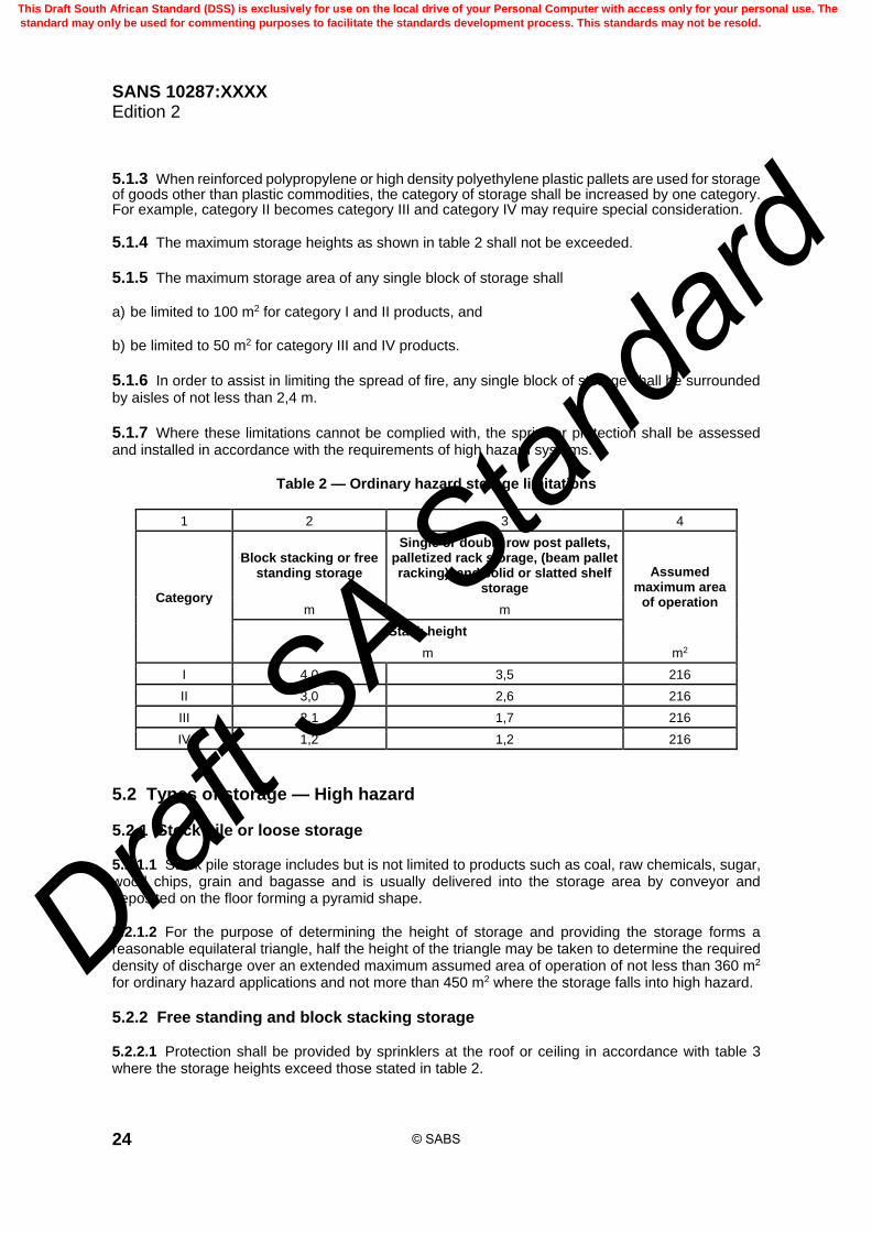
SANS 10287:XXXX Edition 2
24
5.1.3 When reinforced polypropylene or high density polyethylene plastic pallets are used for storage of goods other than plastic commodities, the category of storage shall be increased by one category. For example, category II becomes category III and category IV may require special consideration.
5.1.4 The maximum storage heights as shown in table 2 shall not be exceeded.
5.1.5 The maximum storage area of any single block of storage shall a) be limited to 100 m2 for category I and II products, and b) be limited to 50 m2 for category III and IV products.
5.1.6 In order to assist in limiting the spread of fire, any single block of storage shall be surrounded by aisles of not less than 2,4 m.
5.1.7 Where these limitations cannot be complied with, the sprinkler protection shall be assessed and installed in accordance with the requirements of high hazard systems.
Table 2 — Ordinary hazard storage limitations
1 2 3 4
Category
Block stacking or free standing storage
Single or double row post pallets, palletized rack storage, (beam pallet racking), and solid or slatted shelf
storage
Assumed maximum area
of operation m m
Stack height
m m2
I 4,0 3,5 216
II 3,0 2,6 216
III 2,1 1,7 216
IV 1,2 1,2 216
5.2 Types of storage — High hazard
5.2.1 Stock pile or loose storage 5.2.1.1 Stock pile storage includes but is not limited to products such as coal, raw chemicals, sugar, wood chips, grain and bagasse and is usually delivered into the storage area by conveyor and deposited on the floor forming a pyramid shape. 5.2.1.2 For the purpose of determining the height of storage and providing the storage forms a reasonable equilateral triangle, half the height of the triangle may be taken to determine the required density of discharge over an extended maximum assumed area of operation of not less than 360 m2 for ordinary hazard applications and not more than 450 m2 where the storage falls into high hazard.
5.2.2 Free standing and block stacking storage 5.2.2.1 Protection shall be provided by sprinklers at the roof or ceiling in accordance with table 3 where the storage heights exceed those stated in table 2.
© SABS
This Draft South African Standard (DSS) is exclusively for use on the local drive of your Personal Computer with access only for your personal use. The
standard may only be used for commenting purposes to facilitate the standards development process. This standards may not be resold.
Draft S
A Stan
dard

SANS 10287:XXXX Edition 2
25
5.2.2.2 The maximum storage areas shall not exceed 150 m2 in plan area for any single block of storage and shall be surrounded by aisles of not less than 2,4 m where table 3 is used.
5.2.3 Storage in post or box pallets 5.2.3.1 Where single row post pallet storage stack heights exceed that stated in table 2, the roof or ceiling protection shall be in accordance with table 4. 5.2.3.2 The aisle width between single row post pallets shall not be less than 2,4 m wide. 5.2.3.3 When post or box pallets have solid bottoms, the storage is classed as solid shelves and table 5 shall be used. 5.2.3.4 Where the storage has more than two pallets in more than one direction in the horizontal plane, sprinkler protection at the roof or ceiling shall be used in accordance with table 5.
5.2.4 Storage on solid or slatted shelves 5.2.4.1 Within high hazard occupancies, intermediate level sprinklers shall be fitted under all solid or slatted shelves which exceed 1,0 m in width. 5.2.4.2 Where shelves are positioned back to back and the total width exceeds 1,0 m, a clear longitudinal flue space of 150 mm between shelves shall be maintained. Should the storage height exceed that stated in table 5 for roof or ceiling protection only, intermediate level protection at every tier level with the sprinklers staggered in relation to adjacent tier levels will be required. 5.2.4.3 Where storage heights exceed that given in table 2, protection in accordance with table 5 shall be used for roof or ceiling level. Should the storage heights given in table 5 be exceeded, intermediate sprinklers are required. 5.2.4.4 If it is impossible to install intermediate sprinklers, the plan area of any block of shelved storage shall not exceed 150 m2 with each block of storage being surrounded by aisles of not less than 2,4 m wide. 5.2.4.5 In order to limit the horizontal spread of fire within a shelf, continuous non-combustible vertical bulkheads shall be installed within a shelving configuration where it is impossible to install intermediate sprinklers. 5.2.4.6 Where such bulkheads are installed and the stored goods extend into the aisles beyond the face of the rack, the bulkheads shall also extend beyond the rack at least as far as the storage. 5.2.4.7 Where the aisle widths between any two adjacent shelves are less than 1,2 m, intermediate sprinkler protection shall be installed.
5.2.5 Storage in multiple row, drive through, push back and live racks Intermediate sprinklers shall be used where the storage has more than two pallets in more than one direction in the horizontal plane.
5.2.6 Palletized rack storage (beam pallet racking) 5.2.6.1 The appropriate density of discharge and assumed maximum area of operation according to the category and stack height where beam pallet racking can be protected by roof or ceiling are given in table 4.
© SABS
This Draft South African Standard (DSS) is exclusively for use on the local drive of your Personal Computer with access only for your personal use. The
standard may only be used for commenting purposes to facilitate the standards development process. This standards may not be resold.
Draft S
A Stan
dard

SANS 10287:XXXX Edition 2
26
5.2.6.2 Intermediate level protection shall provide for heights above those indicated in table 4, but where this cannot be achieved, storage configurations shall be provided in accordance with this standard. 5.2.6.3 Rack storage with aisles less than 1,2 m in width or where storage takes place within the aisles shall be treated as multiple row racks due to the ease in which a fire can be radiated from rack to rack and shall have intermediate sprinkler protection installed in accordance with this standard.
6 Protection by sprinklers at the roof or ceiling only
6.1 Free standing storage or block stacking
6.1.1 Table 3 indicates the appropriate density of discharge and assumed maximum area of operation according to the category and stack height where free standing or block storage is to be protected by roof or ceiling protection only.
6.1.2 It is recommended that the actual or assumed height of storage should provide for any future requirements which normally shall not be less than eaves height or to a height 1,0 m below any flat ceiling or roof.
6.1.3 The storage heights of 7,6 m, 7,5 m, 7,2 m and 4,4 m for categories I, II, III and IV respectively indicated in table 3 are deemed to be the maximum for efficient sprinkler protection where sprinklers are provided at the roof or ceiling level only. The design densities of discharge shall not be interpolated.
6.1.4 When reinforced polypropylene or high density polyethylene plastic pallets are used for storage of goods the category of storage shall be classed as Category III. Category IV may require special consideration.
Table 3 — Free standing and block storage
1 2 3 4 5 6
Category I Category II Category III Category IV Design density of
discharge required Assumed maximum
area of operation Stack height
m mm/min m2
5,3 4,1 2,9 1,6 7,5 260
6,5 5,0 3,5 2,0 10,0 260
7,6 5,9 4,1 2,3 12,5 260
–
6,7 4,7 2,7 15,0 260
7,5 5,2 3,0 17,5 260
–
5,7 3,3 20,0 300
6,3 3,6 22,5 300
6,7 3,8 25,0 300
7,2 4,1 27,5 300
4,4 30,0 300
6.2 Rack or post pallet storage
6.2.1 Table 4 indicates the appropriate density of discharge and assumed maximum area of operation according to the category and storage height where single or double row post pallets or palletized rack storage (beam pallet racking), is to be protected.
© SABS
This Draft South African Standard (DSS) is exclusively for use on the local drive of your Personal Computer with access only for your personal use. The
standard may only be used for commenting purposes to facilitate the standards development process. This standards may not be resold.
Draft S
A Stan
dard

SANS 10287:XXXX Edition 2
27
6.2.2 It is recommended that the actual or assumed height of storage should provide for any future requirements which normally shall not be less than eaves height or to a height 1,0 m below any flat ceiling or roof.
Table 4 — Rack and single row post pallet storage
1 2 3 4 5 6
Category I Category II Category III Category IV Design density of discharge
required
Assumed maximum area of operation Stack height
m mm/min m2
4,7 3,4 2,2 1,6 7,5 260
5,7 4,2 2,6 2,0 10,0 260
6,8 5,0 3,2 2,3 12,5 260
–
5,6 3,7 2,7 15,0 260
6,0 4,1 3,0 17,5 260
–
4,4 3,3 20,0 300
4,8 3,6 22,5 300
5,3 3,8 25,0 300
5,6 4,1 27,5 300
6,0 4,4 30,0 300
6.2.3 The storage heights of 6,8 m, 6,0 m, 6,0 m and 4,4 m for categories I, II, III and IV respectively indicated in table 4 are deemed to be the maximum for efficient sprinkler protection where sprinklers are provided at the roof or ceiling level only. The design densities of discharge shall not be interpolated.
6.2.4 When reinforced polypropylene or high density polyethylene plastic pallets are used for storage of goods the category of storage shall be classed as Category III. Category IV may require special consideration.
6.3 General requirements applicable to protection by sprinklers at the roof or ceiling
6.3.1 Standard response sprinklers with a nominal temperature rating of 93 °C shall be used at the roof or ceiling for all high hazard protection unless otherwise noted.
6.3.2 Lower operating temperature sprinklers shall be used for products that produce an initial low heat output such as baled cotton or protection low temperature structures such as cold rooms and freezers.
6.3.3 Where table 4 is used and in order to provide structural integrity and stability, all building columns located within the racks, if not protected by non-combustible materials with a minimum fire resistance of 2 h shall be wetted for cooling purposes by additional sprinklers at the rate of 10,0 mm per minute per square metre over one side of the surface area of the structural member.
6.3.4 Sprinklers shall be positioned at 4,5 m vertical intervals in order to provide uninterrupted rundown below the level of the roof or ceiling level sprinklers.
© SABS
This Draft South African Standard (DSS) is exclusively for use on the local drive of your Personal Computer with access only for your personal use. The
standard may only be used for commenting purposes to facilitate the standards development process. This standards may not be resold.
Draft S
A Stan
dard

SANS 10287:XXXX Edition 2
28
6.3.5 The discharge from these sprinklers within the assumed maximum area of operation shall be included in the water supply and hydraulic calculation considerations.
6.3.6 Whenever possible sprinkler systems shall be installed on the wet pipe system. In unheated buildings alternate wet and dry pipe systems shall be allowed provided that the design area of sprinkler operation is increased by 25 %. Dry pipe systems shall not be intermixed with wet pipe systems, for example, a dry pipe system within racks and wet pipe installation at roof or ceiling level.
6.4 Protection by sprinklers at the roof or ceiling in conjunction with intermediate level protection in storage racks
6.4.1 Location of intermediate level sprinklers in palletized rack storage 6.4.1.1 The design density for the roof or ceiling sprinklers shall be a minimum of 7,5 mm per minute over an assumed maximum area of operation of 260 m2. 6.4.1.2 Where the building is classed as a rack clad where the racks or shelves support the roof or ceiling structure the design density for the roof or ceiling sprinklers shall be a minimum of 10,0 mm per minute over an assumed maximum area of operation of 260 m2. 6.4.1.3 If goods are stored above the highest level of intermediate protection, the design criteria for the roof or ceiling sprinklers shall be taken from table 6. 6.4.1.4 Relative movement can occur between the sprinkler pipework within storage racking that is not fixed to the structure and the distribution pipework that is attached to the building structure. Where movement can be reasonably expected, a flexible swivel joint shall be fitted to the distribution mains at the point of connection. 6.4.1.5 Pipe couplings shall not be used in place of or replace flexible couplings to take up any mild misalignment that may occur due to normal movement. 6.4.1.6 Flexible pipes and swivel joint shall a) be capable of withstanding a test pressure four times the maximum working pressure, or 4000 kPa,
whichever is the greater, and shall not include parts that might impair either the integrity or the performance of sprinkler installations when subjected to fire,
b) not be used to compensate for misalignment between the distribution main and the feed pipe to
intermediate sprinklers, c) contain a continuous pressure retaining inner tube of stainless steel or non-ferrous metal, and d) not be fitted in the fully extended condition. 6.4.1.7 Longitudinal and transverse flues are critical in respect of channelling the passage of heat and water penetration by the sprinklers and shall be continuous for the full height of each block of storage, vertically aligned, free of stored goods, and regularly spaced. (See figure 1.)
© SABS
This Draft South African Standard (DSS) is exclusively for use on the local drive of your Personal Computer with access only for your personal use. The
standard may only be used for commenting purposes to facilitate the standards development process. This standards may not be resold.
Draft S
A Stan
dard

SANS 10287:XXXX Edition 2
29
Figure 1 — Typical rack terminology 6.4.1.8 Sprinkler protection of racks positioned back to back shall be installed within the longitudinal flue spaces at the intersections of the transverse flue. 6.4.1.9 For single racks the sprinklers shall be positioned on the opposing side of the access aisle. 6.4.1.10 It shall be ensured that the water distribution pattern from a sprinkler penetrate the goods stored. 6.4.1.11 Wherever any rack or structural steelwork is likely to interfere with the sprinkler distribution pattern, additional sprinkler protection shall be provided and taken into account in the hydraulic calculations. 6.4.1.12 Where columns are placed between racks positioned back to back and these disrupt the regular spacing of the intermediate sprinklers in relation to the transverse flues or will significantly interfere with the water distribution pattern, a sprinkler shall be placed within 75 mm of either side of the column. The sprinkler range shall be positioned centrally in relation to the column and the rear face of each side of the storage as shown in figure 2. 6.4.1.13 Where the sprinkler exceeds 250 mm from the face of storage, two rows of sprinklers shall be installed within the longitudinal flue space staggered in relation to the opposing level of protection. 6.4.1.14 The distance between goods stored in racks positioned back to back, (longitudinal flue), and between adjacent pallets, (transverse flue), shall not be less than 150 mm and, if required, stops shall be fitted in order to maintain the minimum distances. 6.4.1.15 Where pallets touch in back-to-back racking, the storage configuration shall be regarded as solid shelving, and the protection shall be adjusted in accordance with this standard. 6.4.1.16 The minimum vertical clearance between the spray pattern sprinkler deflector and the stored goods shall not be less than 100 mm and shall be maintained.
© SABS
This Draft South African Standard (DSS) is exclusively for use on the local drive of your Personal Computer with access only for your personal use. The
standard may only be used for commenting purposes to facilitate the standards development process. This standards may not be resold.
Draft S
A Stan
dard

SANS 10287:XXXX Edition 2
30
Figure 2 — Location of intermediate sprinklers in relation to columns
and rear face of storage
6.4.2 Maximum vertical distance between sprinklers 6.4.2.1 For category I, II and III goods the vertical distance from the floor and between tier levels of intermediate protection shall not exceed 3,5 m or every second tier level, whichever is the lesser. 6.4.2.2 For category IV goods the vertical distance from the floor and between tier levels of intermediate protection shall not exceed 2,3 m and shall be positioned at every tier level. 6.4.2.3 An intermediate level of protection shall be installed above the top of storage except where the top of storage is within 4,0 m of the roof or ceiling level protection. 6.4.2.4 The highest level of intermediate sprinkler protection shall not be installed lower than one tier below the top of the storage. 6.4.2.5 Where the highest level of intermediate sprinkler protection is one tier below the top of storage, the design density of discharge at roof or ceiling level shall be in accordance with table 6.
6.4.3 Maximum horizontal distance between sprinklers 6.4.3.1 In the case of category I and II goods the sprinklers shall be positioned within the longitudinal flue and at the intersection of every second pallet transverse flue or a maximum of 3,75 m, whichever is the lesser as shown in figure 3. 6.4.3.2 The sprinklers shall be staggered in relation to the next highest row and the product of the horizontal and vertical distances between the sprinklers for category I and II goods shall not exceed 9,8 m2 (see figure 3).
© SABS
This Draft South African Standard (DSS) is exclusively for use on the local drive of your Personal Computer with access only for your personal use. The
standard may only be used for commenting purposes to facilitate the standards development process. This standards may not be resold.
Draft S
A Stan
dard

SANS 10287:XXXX Edition 2
31
Figure 3 — Location of intermediate protection sprinklers for category I or II 6.4.3.3 In the case of category III goods the sprinklers shall be positioned within the longitudinal flue and at the intersection of every pallet transverse flue or a maximum of 1,9 m, whichever is the lesser (see figure 4). 6.4.3.4 In the case of category IV goods the sprinklers shall be positioned at every tier level within the longitudinal flue and at the intersection of every second pallet transverse flue or a maximum of 2,8 m, whichever is the lesser (see figure 5). 6.4.3.5 For category III and IV goods the sprinklers shall be staggered in relation to the next highest row and the product of the horizontal and vertical distances between the sprinklers shall not exceed 4,9 m2 (see figure 4 and figure 5).
6.4.4 Rack widths 6.4.4.1 The number of rows of sprinklers shall be determined by the rack width in accordance with 6.4.4.3. 6.4.4.2 Where racks are positioned back to back, the total width shall be calculated by adding together the width of each pallet and the distance between them. 6.4.4.3 The maximum width of back to back beam pallet racking shall not exceed 3,2 m which allows a maximum ingress of 1,6 m from centre of the longitudinal flue to the outside face of the pallet.
© SABS
This Draft South African Standard (DSS) is exclusively for use on the local drive of your Personal Computer with access only for your personal use. The
standard may only be used for commenting purposes to facilitate the standards development process. This standards may not be resold.
Draft S
A Stan
dard
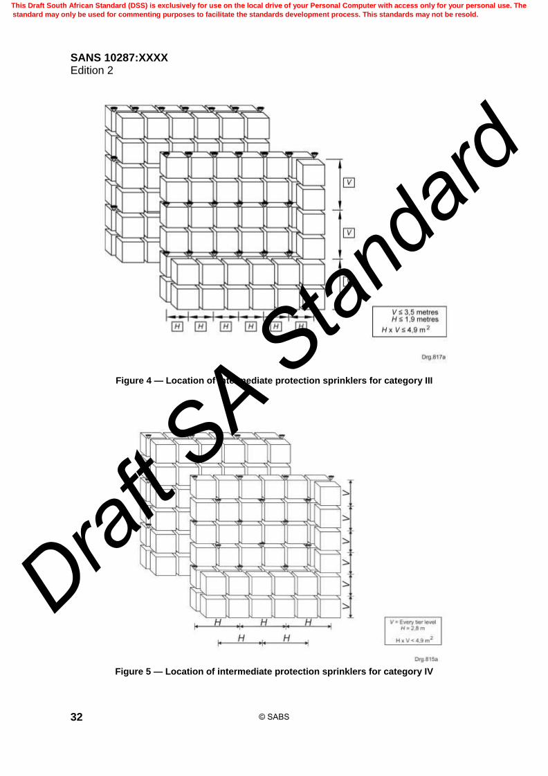
SANS 10287:XXXX Edition 2
32
Figure 4 — Location of intermediate protection sprinklers for category III
Figure 5 — Location of intermediate protection sprinklers for category IV
© SABS
This Draft South African Standard (DSS) is exclusively for use on the local drive of your Personal Computer with access only for your personal use. The
standard may only be used for commenting purposes to facilitate the standards development process. This standards may not be resold.
Draft S
A Stan
dard
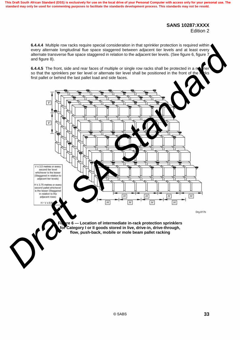
SANS 10287:XXXX Edition 2
33
6.4.4.4 Multiple row racks require special consideration in that sprinkler protection is required within every alternate longitudinal flue space staggered between adjacent tier levels and at least every alternate transverse flue space staggered in relation to the adjacent tier levels. (See figure 6, figure 7 and figure 8). 6.4.4.5 The front, side and rear faces of multiple or single row racks shall be protected in a manner so that the sprinklers per tier level or alternate tier level shall be positioned in the front of the racks first pallet or behind the last pallet load and side faces.
Figure 6 — Location of intermediate in-rack protection sprinklers for Category I or II goods stored in live, drive-in, drive-through,
flow, push-back, mobile or mole beam pallet racking
© SABS
This Draft South African Standard (DSS) is exclusively for use on the local drive of your Personal Computer with access only for your personal use. The
standard may only be used for commenting purposes to facilitate the standards development process. This standards may not be resold.
Draft S
A Stan
dard
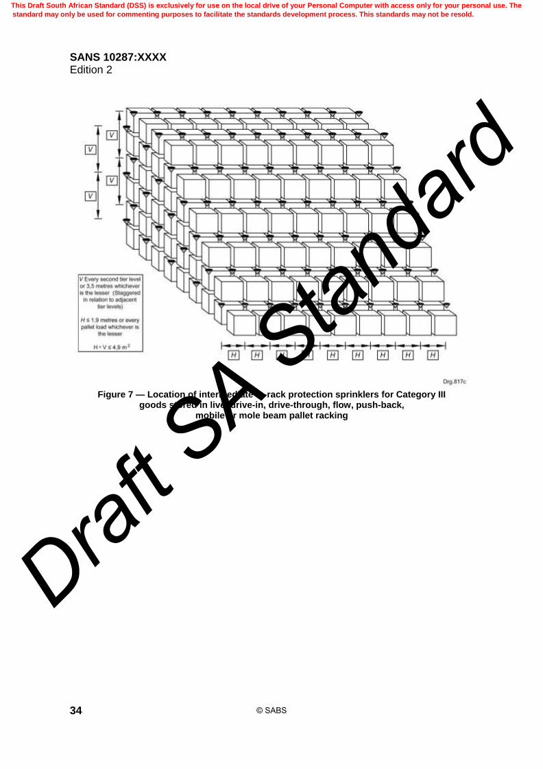
SANS 10287:XXXX Edition 2
34
Figure 7 — Location of intermediate in-rack protection sprinklers for Category III
goods stored in live, drive-in, drive-through, flow, push-back, mobile or mole beam pallet racking
© SABS
This Draft South African Standard (DSS) is exclusively for use on the local drive of your Personal Computer with access only for your personal use. The
standard may only be used for commenting purposes to facilitate the standards development process. This standards may not be resold.
Draft S
A Stan
dard

SANS 10287:XXXX Edition 2
35
Figure 8 — Location of intermediate in-rack protection sprinklers for Category IV goods stored in live, drive-in, drive-through, flow, push-back,
mobile or mole beam pallet racking
6.4.5 Positioning of the sprinkler deflector 6.4.5.1 Where possible the pipework and sprinkler shall be installed in a position that will obviate damage when pallets or goods are being loaded or unloaded into shelves or beam pallet racks. 6.4.5.2 Unless the manufacturer’s requirements differ in respect of the minimum distance that a deflector may be beneath the escutcheon plate of a semi-concealed sprinkler, the minimum distance a sprinkler deflector shall be beneath the framework of a beam pallet rack or longitudinal flue where shelves are positioned back-to-back shall not be less than 25 mm. This measurement shall be taken after beam deflection to account for storage loading.
6.4.6 Excessive clearance 6.4.6.1 The values from tables 2, 3, 4, 5 and table 6 where applicable shall be used to determine the clearance. 6.4.6.2 Where, in any instance, the clearance distance between the storage height and the ceiling sprinkler deflector, exceeds 4,0 m in excess of that allowable when applying table 6, intermediate levels of in-rack sprinklers shall be provided in accordance with this standard above the top of storage for control mode sprinkler protection taking into consideration the alternatives given in 6.4.6.3 and 6.4.6.4.
© SABS
This Draft South African Standard (DSS) is exclusively for use on the local drive of your Personal Computer with access only for your personal use. The
standard may only be used for commenting purposes to facilitate the standards development process. This standards may not be resold.
Draft S
A Stan
dard

SANS 10287:XXXX Edition 2
36
6.4.6.3 Where, in any instance, the clearance distance between the storage height and the ceiling sprinkler deflector, exceeds 4,0 m in excess of that allowable when applying table 6 but not more than 10,0 m, the following shall be applied for control mode sprinkler protection: a) the roof or ceiling level design density of discharge shall be in accordance with tables 2, 3, 4 and
5 as applicable but shall not be less than 12,5 mm per minute; b) the assumed maximum area of operation shall be increased by 25 % in accordance with the table
under consideration, and c) the roof level sprinklers operating temperature shall not exceed 93o C and a K-Factor of
minimum 11,5 shall be used. 6.4.6.4 Where, in any instance, the clearance distance between the storage height and the ceiling sprinkler deflector, exceeds 4,0 m in excess of that allowable when applying table 6, the following may be applied for control mode sprinkler protection: a) increase the roof level design density of discharge for the first excessive metre or part thereof by
2,5 mm per minute; and b) for each additional metre or part thereof, increase the design density of discharge by 1,0 mm per
minute. 6.4.6.5 The roof level sprinklers operating temperature shall not exceed 93o C and a K-Factor of minimum 11,5 shall be used.
6.5 Location of intermediate level shelf sprinkler in solid or slatted shelved storage racks
6.5.1 Where intermediate sprinklers are required they shall be installed at every tier level of the shelf and above the top of stored goods on the uppermost shelf level if the roof or ceiling sprinklers are more than 4,0 m above the goods or water access to the goods is restricted.
6.5.2 Sprinklers in storage racks with solid or slatted shelves shall be located centrally beneath each shelf or shelves not exceeding 3,0 m in width. See figure 9.
6.5.3 Where the shelves exceed 3,0 m but are less than 6,0 m in width, two rows of sprinklers shall be provided. Where shelf width exceed 6,0 m, special consideration is required.
6.5.4 The horizontal spacing of sprinklers within the tier levels shall not exceed 2,8 m irrespective of the category of goods (see figure 9).
6.5.5 The distance from the end of the shelf perpendicular to the range pipelines within a shelf to the nearest sprinkler shall not exceed half the sprinkler spacing or 1,4 m, whichever is the lesser (see figure 9).
6.5.6 The distance from the end of the shelf parallel to the range pipelines within a shelf to the nearest sprinkler shall not exceed 1,5 m.
6.5.7 Where shelves are positioned back to back and a longitudinal flue space is used to protect the tier levels, the sprinklers shall be staggered in relation to the next tier level as shown in figure 9.
© SABS
This Draft South African Standard (DSS) is exclusively for use on the local drive of your Personal Computer with access only for your personal use. The
standard may only be used for commenting purposes to facilitate the standards development process. This standards may not be resold.
Draft S
A Stan
dard
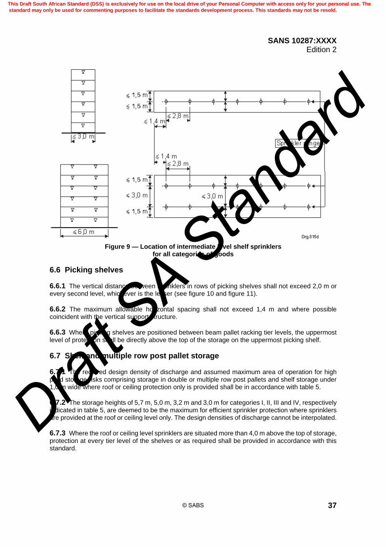
SANS 10287:XXXX Edition 2
37
Figure 9 — Location of intermediate level shelf sprinklers
for all categories of goods
6.6 Picking shelves
6.6.1 The vertical distance between sprinklers in rows of picking shelves shall not exceed 2,0 m or every second level, whichever is the lesser (see figure 10 and figure 11).
6.6.2 The maximum allowable horizontal spacing shall not exceed 1,4 m and where possible coincident with the vertical support structure.
6.6.3 Where picking shelves are positioned between beam pallet racking tier levels, the uppermost level of protection shall be directly above the top of the storage on the uppermost picking shelf.
6.7 Shelf and multiple row post pallet storage
6.7.1 The required design density of discharge and assumed maximum area of operation for high piled storage risks comprising storage in double or multiple row post pallets and shelf storage under 1,0 m wide where roof or ceiling protection only is provided shall be in accordance with table 5.
6.7.2 The storage heights of 5,7 m, 5,0 m, 3,2 m and 3,0 m for categories I, II, III and IV, respectively indicated in table 5, are deemed to be the maximum for efficient sprinkler protection where sprinklers are provided at the roof or ceiling level only. The design densities of discharge cannot be interpolated.
6.7.3 Where the roof or ceiling level sprinklers are situated more than 4,0 m above the top of storage, protection at every tier level of the shelves or as required shall be provided in accordance with this standard.
© SABS
This Draft South African Standard (DSS) is exclusively for use on the local drive of your Personal Computer with access only for your personal use. The
standard may only be used for commenting purposes to facilitate the standards development process. This standards may not be resold.
Draft S
A Stan
dard

SANS 10287:XXXX Edition 2
38
Table 5 — Shelf and multiple row post pallet storage
1 2 3 4 5 6
Category I
Category II
Category III
Category IV Design density of
discharge required Assumed maximum
area of operation Stack height
m mm/min m2
4,7 3,4 2,2 1,6 7,5 260
5,7 4,2 2,6 2,0 10,0 260
–
5,0 3,2 2,3 12,5 260
– – 2,7 15,0 260
3,0 17,5 260
Figure 10 — Location of intermediate sprinklers in picking shelves
© SABS
This Draft South African Standard (DSS) is exclusively for use on the local drive of your Personal Computer with access only for your personal use. The
standard may only be used for commenting purposes to facilitate the standards development process. This standards may not be resold.
Draft S
A Stan
dard

SANS 10287:XXXX Edition 2
39
Figure 11 — Typical location of intermediate sprinklers when shelves are intermixed with beam pallet racking
6.8 Roof or ceiling sprinkler design criteria with intermediate sprinklers
6.8.1 A maximum vertical distance of not more than 4,0 m between the top of the stored goods and the roof or ceiling level protection is permitted in accordance with table 6.
6.8.2 Where the distance between roof or ceiling level protection is less than 4,0 m, a clear vertical distance of not less than 1,0 m shall be maintained between sprinkler deflector and stored goods subject to the limitations of table 6.
6.8.3 Dry and alternate systems shall be not be used but where necessary, the assumed maximum area of operation shall be increased by 25 % using standard response sprinklers.
© SABS
This Draft South African Standard (DSS) is exclusively for use on the local drive of your Personal Computer with access only for your personal use. The
standard may only be used for commenting purposes to facilitate the standards development process. This standards may not be resold.
Draft S
A Stan
dard

SANS 10287:XXXX Edition 2
40
Table 6 — Roof or ceiling sprinkler design criteria with intermediate sprinklers
1 2 3 4 5 6 7
Storage configuration
Maximum permitted storage height above the top level of intermediate protection Design
density
Assumed maximum
area of operation m
Category I Category II Category III Category IV mm/min m2
Palletized racks
3,5 3,4 2,2 1,6 7,5 260
– – 2,2 1,6 7,5 260
2,6 2,0 10,0 260
3,2 2,3 12,5 260
3,5 2,7 15,0 260
Solid or slatted shelves
3,5 3,4 2,2 1,6 7,5 260
– – 2,6 2,0 10,0 260
3,2 2,3 12,5 260
– 2,7 15,0 260
6.9 General requirements applicable to protection by sprinklers at the roof or ceiling in conjunction with intermediate level protection in storage racks
6.9.1 High temperature rated standard response sprinklers with a nominal temperature rating of 93 °C or as specified in this standard shall be used at the roof or ceiling whereas: a) K8,0, 68 °C nominal operating temperature pendent spray pattern fast response sprinklers with a
response time index of less than 50 shall be used at intermediate levels in the racks or shelves; and
b) K11,5, 68 °C nominal temperature pendent spray pattern fast response sprinklers with a response
time index of less than 50 shall be used at intermediate levels in picking shelves.
6.9.2 If the roof or ceiling protection is more than 4,0 m above the top of storage, the row of intermediate sprinklers that would normally be located above the top of the storage may be omitted if the roof or ceiling level protection sprinklers are at 93 °C operating temperature with a fast response rating.
6.9.3 Each intermediate level sprinkler in palletized rack storage and storage on slatted shelves shall be fitted with a metal water shield of 75 mm in diameter which is approved and listed. This precaution will not normally be necessary for sprinklers beneath solid shelves or where the sprinkler is shielded by horizontal barriers. In the case of upright sprinklers, the assembly supporting the shield shall cause minimum obstruction to the water distribution.
6.9.4 Consideration shall be given to the protection of pipework and sprinklers against mechanical damage.
6.9.5 Sprinkler guards which are approved and listed, shall be fitted to intermediate sprinkler protection for palletized rack protection, solid or slatted shelves.
6.9.6 Sprinkler tiers shall be calculated from the top of the storage.
6.9.7 Sprinkler protection is required in every longitudinal flue space regardless of configuration.
© SABS
This Draft South African Standard (DSS) is exclusively for use on the local drive of your Personal Computer with access only for your personal use. The
standard may only be used for commenting purposes to facilitate the standards development process. This standards may not be resold.
Draft S
A Stan
dard

SANS 10287:XXXX Edition 2
41
6.10 Location of sprinklers beneath storage mezzanine floors (see figures 12 – 17)
6.10.1 Where storage in shelving not exceeding the heights given in table 5 or beam pallet racking and single row post pallet storage with storage heights not exceeding those stated in table 4 takes place beneath a mezzanine floor, special consideration shall be given to the sprinkler protection as indicated in 6.9.
6.10.2 Aisle protection alone without longitudinal flue protection for mezzanine levels shall not exceed the storage heights given in table 4 or table 5 regardless of the method of storage employed.
6.10.3 Preference shall be given to the positioning of the sprinklers centrally within the aisles over other services. Where this cannot be achieved, additional rows of protection may be provided and the inclusion of baffles in order to prevent wetting of adjacent sprinklers.
6.10.4 The aisle width shall determine the positioning and location of the sprinklers where shelves or pallets are positioned back to back and a clear 150 mm longitudinal flue space is maintained.
6.10.5 Where half the aisle width and half the shelf or pallet width do not exceed 1,5 m, 1 row of sprinklers centrally located in the aisle shall be provided. The sprinklers shall be staggered in relation to the sprinklers in the adjacent aisle.
6.10.6 Where half the aisle width and half the shelf or pallet width exceeds 1,5 m but does not exceed 3,0 m, two rows of sprinklers shall be provided within the aisle. The sprinklers within the aisles shall be staggered in relation to the opposing row of sprinklers and those in the adjacent aisle.
6.10.7 Where half the aisle width and half the shelf or pallet width exceeds 3,0 m sprinkler protection shall be provided within the aisle and centrally located at every shelf level or in the longitudinal flue space of beam pallet racks.
6.10.8 Where it is not possible to protect within the shelf due to, for example, limited tier level heights, two rows of sprinkler protection shall be provided within the aisles positioned directly above the storage face and staggered in relation to the opposing row of sprinklers.
6.10.9 The sprinklers installed within the aisle, shelf or rack shall be stagger spaced in the horizontal plane, at horizontal intervals of not more than 2,8 m along the length of the aisle, shelf or rack.
6.10.10 Longitudinal and transverse non-combustible vertical bulkheads compartmentalising the shelving or racking into areas not exceeding 150 m2 in floor area shall be installed.
6.10.11 If an aisle requiring two rows of sprinklers is of a width where the sprinklers will be closer than 2,0 m apart, and the maximum allowable shelf ingress of 1,5 m is exceeded, intermediate level shelf protection shall be provided.
6.10.12 In all cases, means shall be provided to prevent the vertical spread of fire to above the mezzanine floor.
6.10.13 The sprinklers shall not be positioned closer than 250 mm from the face of the shelf which allows for a maximum allowable ingress of 1,25 m.
6.10.14 A clear space of not less than 150 mm shall be maintained between sprinkler deflector and top of stored goods at each mezzanine level and 1,0 m between top of stored goods and roof or ceiling protection subject to the design density of discharge and storage heights being in accordance with table 3, table 4 or table 5.
© SABS
This Draft South African Standard (DSS) is exclusively for use on the local drive of your Personal Computer with access only for your personal use. The
standard may only be used for commenting purposes to facilitate the standards development process. This standards may not be resold.
Draft S
A Stan
dard

SANS 10287:XXXX Edition 2
42
6.10.15 Fast response, spray pattern sprinklers shall be used for aisle protection whether or not exposed steel is present and the underside of solid mezzanine floors or mezzanine floors with combustible content located beneath them.
6.10.16 Fast response upright flat spray pattern sprinklers with a response time index of less than 50 rated at an operating temperature of 68o C with a K-Factor of not less than 8,0 shall be used for the protection of mezzanine levels. The sprinklers shall be fitted with sprinkler guards which are approved.
6.10.17 Fast response conventional pattern sprinklers with a response time index of less than 50 and an operating temperature of 93o C with a K-Factor of not less than 8,0 shall be used for the protection of the roof or ceiling level.
6.10.18 Where sprinklers are located in the longitudinal flue space or centrally located beneath shelf tier levels as well as within the aisles, 68o C operating temperature, fast response spray pattern sprinklers shall be used.
6.10.19 If the mezzanine floor is not solid in construction, water shields shall be fitted to the sprinklers.
6.10.20 In order to minimise damage to the sprinklers, upright spray pattern sprinklers shall be used where possible. Mezzanine sprinklers are deemed to be subject to damage and, regardless of the orientation of the sprinkler, they shall be fitted with sprinkler guards which are approved.
6.11 Multiple level mezzanine storage (see figures 12 to 17)
6.11.1 The requirements of 6.10 shall apply where applicable.
6.11.2 Where beam pallet storage takes place and the pallets are positioned back to back, consideration can be given to increased storage heights where protection is positioned within the longitudinal flue of the tier levels and aisles in accordance with this standard.
6.11.3 The sprinklers installed within the aisles, shelf or rack shall be stagger spaced in the horizontal and vertical plane, at horizontal intervals of not more than 2,8 m along the length of the aisle, shelf or rack.
6.11.4 The area of operation at roof level shall be increased by 25 %. The actual design density of discharge at roof level shall be determined by the type of goods stored, the method and height of storage subject to a minimum of 12,5 mm per minute over an assumed maximum area of operation of not less than 325 m2.
6.11.5 The area of operation at each mezzanine level shall be increased by 25 %. The design density of discharge at each mezzanine level shall be determined by the type of goods stored, the method and height of storage subject to a minimum of 10,0 mm per minute over an assumed maximum area of operation of not less than 325 m2.
6.11.6 Proving of the system where not more than two mezzanine levels are installed shall encompass, at the required design density of discharge for each area: a) the operation of four adjacent sprinklers on three adjacent rows encompassing two mezzanine
levels, and b) the balance of protection making up the full design area of operation taken from the roof or ceiling
protection.
© SABS
This Draft South African Standard (DSS) is exclusively for use on the local drive of your Personal Computer with access only for your personal use. The
standard may only be used for commenting purposes to facilitate the standards development process. This standards may not be resold.
Draft S
A Stan
dard

SANS 10287:XXXX Edition 2
43
6.11.7 Proving of the system where three or more mezzanine levels are installed shall encompass, at the required design density of discharge for each area: a) the operation of three adjacent sprinklers on three adjacent rows encompassing three mezzanine
levels, and b) the balance of protection, but not less than 9 sprinklers, making up the full design area of operation
taken from the roof or ceiling protection.
6.11.8 Where ESFR sprinklers are installed at roof or ceiling level 6 sprinklers only need to be taken into simultaneous operation with the mezzanine floors.
6.11.9 In order to limit the horizontal and vertical spread of fire within a shelf, continuous non-combustible vertical and horizontal bulkheads shall be installed within a shelving configuration where it is impossible to install intermediate level sprinklers in risks such as document warehousing.
6.12 Document storage The requirements of 6.10 and 6.11 shall apply where applicable. Additionally, sprinkler protection shall be located centrally over the shelf storage at each tier or walkway level within the longitudinal flue. The maximum allowable single shelf width shall not exceed 3,0 m and shall have a clear longitudinal flue space of not less than 150 mm centrally located into which no goods may protrude. The sprinkler protection shall be staggered relative to each tier or walkway level.
Figure 12 — Typical location of sprinklers beneath a mezzanine floor ≤ 1 500 mm wide
© SABS
This Draft South African Standard (DSS) is exclusively for use on the local drive of your Personal Computer with access only for your personal use. The
standard may only be used for commenting purposes to facilitate the standards development process. This standards may not be resold.
Draft S
A Stan
dard

SANS 10287:XXXX Edition 2
44
Figure 13 — Typical location of sprinklers beneath a mezzanine floor ≤ 1 500 mm but ≤ 3 000 mm wide
Figure 14 — Typical location of sprinklers beneath a mezzanine floor ≥ 3 000 mm wide
© SABS
This Draft South African Standard (DSS) is exclusively for use on the local drive of your Personal Computer with access only for your personal use. The
standard may only be used for commenting purposes to facilitate the standards development process. This standards may not be resold.
Draft S
A Stan
dard

SANS 10287:XXXX Edition 2
45
Figure 15 — Typical location of sprinklers beneath a mezzanine floor
Figure 16 — Typical gridded layout of sprinklers beneath a mezzanine floor
centre of aisle to centre of shelf or racks ≤ 1 500 mm
© SABS
This Draft South African Standard (DSS) is exclusively for use on the local drive of your Personal Computer with access only for your personal use. The
standard may only be used for commenting purposes to facilitate the standards development process. This standards may not be resold.
Draft S
A Stan
dard

SANS 10287:XXXX Edition 2
46
Figure 17 — Typical gridded layout of sprinklers beneath a mezzanine
floor centre of aisle to centre of shelf or racks ≤ 3000 mm
6.13 Water requirements where rack or shelf protection is installed
6.13.1 Unless otherwise indicated, the pressure and flow requirements of intermediate level sprinklers shall be calculated on the assumption that the hydraulically most unfavourable sprinkler operates at a pressure of not less than 200 kPa when using K8,0 sprinklers and 100 kPa when using K11,5 sprinklers for racks, (subject to 200 kPa discharge pressure in picking shelves using K11,5 sprinklers), when the number of sprinklers in table 7 are in simultaneous operation in the hydraulically most unfavourable or favourable location.
6.13.2 It is strongly recommended that K11,5 sprinklers be used for intermediate level protection.
6.14 Number of intermediate sprinklers in simultaneous operation
6.14.1 Intermediate level sprinklers shall be fed from a separate set of installation control valves.
6.14.2 Where not more than 50 intermediate level sprinklers are installed, they may be fed directly from the ceiling sprinkler distribution pipework, subject to the control valve not being less than 150 mm nominal diameter.
© SABS
This Draft South African Standard (DSS) is exclusively for use on the local drive of your Personal Computer with access only for your personal use. The
standard may only be used for commenting purposes to facilitate the standards development process. This standards may not be resold.
Draft S
A Stan
dard
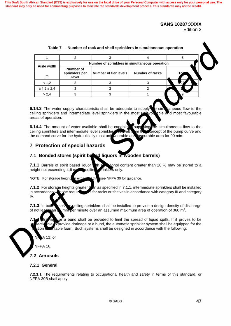
SANS 10287:XXXX Edition 2
47
Table 7 — Number of rack and shelf sprinklers in simultaneous operation
1 2 3 4 5
Aisle width Number of sprinklers in simultaneous operation
Number of sprinklers per
level Number of tier levels Number of racks Total
m
< 1,2 3 3 3 27
≥ 1,2 ≤ 2,4 3 3 2 18
> 2,4 3 3 1 9
6.14.3 The water supply characteristic shall be adequate to supply the simultaneous flow to the ceiling sprinklers and intermediate level sprinklers in the most unfavourable and most favourable areas of operation.
6.14.4 The amount of water available shall be capable of supplying the simultaneous flow to the ceiling sprinklers and intermediate level sprinklers, derived from the intercept of the pump curve and the demand curve for the hydraulically most unfavourable and favourable area for 90 min.
7 Protection of special hazards
7.1 Bonded stores (spirit based liquors in wooden barrels)
7.1.1 Barrels of spirit based liquor with an alcohol content greater than 20 % may be stored to a height not exceeding 4,6 m with ceiling sprinklers only. NOTE For storage heights in excess of this, see NFPA 30 for guidance.
7.1.2 For storage heights greater than as specified in 7.1.1, intermediate sprinklers shall be installed in accordance with the requirements for racks or shelves in accordance with category III and category IV.
7.1.3 In both cases the ceiling sprinklers shall be installed to provide a design density of discharge of not less than 15 mm per minute over an assumed maximum area of operation of 360 m2.
7.1.4 Drainage or a bund shall be provided to limit the spread of liquid spills. If it proves to be impracticable to provide drainage or a bund, the automatic sprinkler system shall be equipped for the injection of suitable foam. Such systems shall be designed in accordance with the following: a) NFPA 11; or b) NFPA 16.
7.2 Aerosols
7.2.1 General 7.2.1.1 The requirements relating to occupational health and safety in terms of this standard, or NFPA 30B shall apply.
© SABS
This Draft South African Standard (DSS) is exclusively for use on the local drive of your Personal Computer with access only for your personal use. The
standard may only be used for commenting purposes to facilitate the standards development process. This standards may not be resold.
Draft S
A Stan
dard
SANS 10287:XXXX Edition 2
48
7.2.1.2 The protection of storage of aerosols is a particular challenge to sprinkler systems. Under fire conditions, failure of an aerosol may occur due to increasing internal pressures caused by the container being subjected to heat. Any failure of a stored aerosol is likely to cause subsequent failure or ejection from the fire site to adjacent aerosols. Tests have shown that under fire conditions unrestrained aerosol containers can travel distances of up to 30,0 m and aerosol caps can travel up to 20,0 m whilst ignited creating a possible secondary ignition source. 7.2.1.3 Aerosol storage is a category IV risk. 7.2.1.4 The base product is product concentrate and all contents of the aerosol container other than the propellant. 7.2.1.5 The term "aerosol" shall refer to an aerosol dispenser, aerosol cap and its contents. 7.2.1.6 An aerosol shall be deemed to have flammable contents if it contains either: a) more than 45 % by weight of flammable substances; or b) more than 250 g of flammable substances. 7.2.1.7 Flammable substances mean highly flammable gases or flammable liquids having closed cup flash points equal to or less than 100 °C.
7.2.2 Segregation of aerosols 7.2.2.1 Aerosols shall be segregated and isolated from other stock, preferably in a separate building or fireproof enclosure with a fire resistance of not less than 120 min. 7.2.2.2 The area of the compartments shall be no greater than the appropriate assumed maximum area of operation as provided by the installation design protecting the aerosol storage. 7.2.2.3 Where this is impracticable, the aerosols shall be totally enclosed within a stout steel mesh cage of appropriate size and strength, including self-closing doors, to prevent rocket ejection of exploding aerosols and parts of aerosols. 7.2.2.4 The plan area of any storage cage shall not exceed 125 m2. Expanded metal or wire mesh may be used providing the metal is: a) at least 2 mm thick and the mesh size does not exceed 25 mm by 25 mm, or b) not lighter than 2,9 mm (9 gauge) steel wire woven into a maximum 50 mm diamond mesh. 7.2.2.5 Small quantities of aerosols may be stored in mesh bins of similar construction. 7.2.2.6 Other than the aerosol packaging, containers and pallets on which aerosols stand, no combustible material shall be stored inside or within 2,5 m of any protective cage. 7.2.2.7 Aerosols shall be stored in a cool, dry, well-ventilated area, free from the risk of freezing, and where the ambient temperature cannot exceed 40 °C. 7.2.2.8 To prevent the possible accumulation of flammable vapours, aerosols shall not be stored in basements or similar sunken areas. 7.2.2.9 Low and high level ventilation direct to the open shall be provided in the storage building or compartment to prevent the accumulation of flammable vapour. This may be achieved by the use of
© SABS
This Draft South African Standard (DSS) is exclusively for use on the local drive of your Personal Computer with access only for your personal use. The
standard may only be used for commenting purposes to facilitate the standards development process. This standards may not be resold.
Draft S
A Stan
dard

SANS 10287:XXXX Edition 2
49
ventilation grills or equivalent. The vent area shall comprise at least 2,5 % of the combined area of the roof (ceiling) and walls. 7.2.2.10 Alternatively, mechanical ventilation may be used, providing at least 6 air changes per hour. Extract shall be at low-level, inlet at high-level, positioned so as to provide cross-flow. Duct openings shall not allow fire spread. Fan motors shall not be positioned within the duct work, and shall be suitable for the hazard zone. 7.2.2.11 Care shall be taken to prevent obstruction of the openings.
7.2.3 Protection of aerosol storage areas 7.2.3.1 Systems shall be of the wet-pipe type only. 7.2.3.2 Conventional or spray pattern sprinklers with a K-Factor of not less than 16,0 shall be used for roof or ceiling protection. 7.2.3.3 Where spray pattern sprinklers are used, the ceiling insulation shall be non-combustible and fire ventilation systems shall be manually operated. 7.2.3.4 Intermediate rack sprinkler protection shall be used. Fast response spray pattern sprinklers with a response time index of less than 50 rated at an operating temperature of 68 °C with a K-Factor of not less than 11,5 shall be used for intermediate protection. The discharge pressure of any operating intermediate sprinkler shall not be less than be 200 kPa. 7.2.3.5 Aerosols stored in free standing or block stacking shall be in accordance with table 8.
© SABS
This Draft South African Standard (DSS) is exclusively for use on the local drive of your Personal Computer with access only for your personal use. The
standard may only be used for commenting purposes to facilitate the standards development process. This standards may not be resold.
Draft S
A Stan
dard
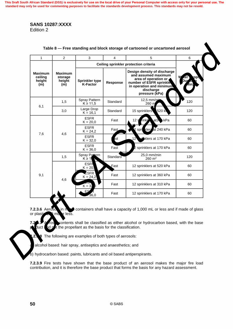
SANS 10287:XXXX Edition 2
50
Table 8 — Free standing and block storage of cartooned or uncartoned aerosol
1 2 3 4 5 6
Maximum ceiling height
(m)
Maximum storage height
(m)
Ceiling sprinkler protection criteria
Water Supply
Duration (Min)
Sprinkler type K-Factor
Response
Design density of discharge and assumed maximum
area of operation or number of ESFR sprinklers in operation and minimum
discharge pressure (kPa)
6,1
1,5 Spray Pattern
K ≥ 11,5 Standard
12,5 mm/min 260 m2
120
3,0 Large Drop
K = 16,1 Standard 15 sprinklers at 520 kPa 120
7,6 4,6
ESFR K = 20,0
Fast 12 sprinklers at340 kPa 60
ESFR K = 24,2
Fast 12 sprinklers at 240 kPa 60
ESFR K = 32,0
Fast 12 sprinklers at 170 kPa 60
ESFR K = 36,0
Fast 12 sprinklers at 170 kPa 60
9,1
1,5 Spray Pattern
K ≥ 16,1 Standard
25,0 mm/min 260 m2
120
4,6
ESFR K = 20,0
Fast 12 sprinklers at 520 kPa 60
ESFR K = 24,2
Fast 12 sprinklers at 360 kPa 60
ESFR K = 32,0
Fast 12 sprinklers at 310 kPa 60
ESFR K = 36,0
Fast 12 sprinklers at 170 kPa 60
7.2.3.6 Aerosols in metal containers shall have a capacity of 1,000 mL or less and if made of glass or plastic 220 mL or less. 7.2.3.7 Aerosol contents shall be classified as either alcohol or hydrocarbon based, with the base product and not the propellant as the basis for the classification. 7.2.3.8 The following are examples of both types of aerosols: a) alcohol based: hair spray, antiseptics and anaesthetics; and b) hydrocarbon based: paints, lubricants and oil based antiperspirants. 7.2.3.9 Fire tests have shown that the base product of an aerosol makes the major fire load contribution, and it is therefore the base product that forms the basis for any hazard assessment.
© SABS
This Draft South African Standard (DSS) is exclusively for use on the local drive of your Personal Computer with access only for your personal use. The
standard may only be used for commenting purposes to facilitate the standards development process. This standards may not be resold.
Draft S
A Stan
dard

SANS 10287:XXXX Edition 2
51
7.2.4 Draught curtains 7.2.4.1 Non-combustible draught curtains shall extend down to a minimum of 0,6 m from the ceiling the underside of the curtain shall run parallel to the floor and be installed at the interface between ordinary and high temperature sprinklers or segregated areas within aerosol storage areas. 7.2.4.2 Smoke and draft curtains fitted at ceiling level within sprinkler arrays to separate differing levels of protection, the sprinklers on either side of the smoke or draft curtain shall be equal in distance to within 200 mm. The distance of sprinklers from the smoke or draft curtain may vary along the length of the curtain if there are changes in the sprinkler spacing.
7.2.4.3 The roof slope shall not exceed 5 for ESFR protection. The area of the design for the required ceiling sprinkler system shall extend 6,0 m beyond any area where the aerosols be stored within a caged off area. 7.2.4.4 The roof or ceiling level design requirements for aerosols stored in racks shall not be less than that stated in given in table 9.
Table 9 — Criteria for aerosol storage
1 2 3 4 5 6
Storage type
Storage height Sprinkler
temperature rating
Ceiling sprinkler density
Assumed maximum
area of operation (AMAO)
m
Alcohol based
Hydrocarbon
baseda °C mm/min m2
Palletized rack Tiers ≤ 1,8 – 93 12,5b 260
– Tiers ≤ 1,8 93 15,0b 260
a Other than alcohol
b Plus intermediate sprinklers
7.2.4.5 Any intermediate sprinklers shall be installed at every tier level of storage at a maximum horizontal spacing of 1,4 m or every pallet. 7.2.4.6 There shall be a minimum vertical clearance of 150 mm between any sprinkler deflector and the storage immediately below. 7.2.4.7 Face sprinklers shall be provided at every alternate tier level or 3,6 m, whichever is the lesser and at the top of storage. These sprinklers shall be spaced at no more than 2,8 m intervals or every second pallet, whichever is the lesser and shall be staggered in relation to the adjacent tier levels. 7.2.4.8 Nine sprinklers are deemed to be in simultaneous operation where one tier level of intermediate protection is installed. 7.2.4.9 Eighteen sprinklers, six sprinklers on two adjacent tier levels, are deemed to be in simultaneous operation where two tier levels of intermediate protection is provided. 7.2.4.10 Twenty-seven sprinklers, six sprinklers on three adjacent tier levels, are deemed to be in simultaneous operation where more than three tier levels of intermediate protection is provided. 7.2.4.11 Minimum aisle widths of not less than 2,4 m shall be maintained.
© SABS
This Draft South African Standard (DSS) is exclusively for use on the local drive of your Personal Computer with access only for your personal use. The
standard may only be used for commenting purposes to facilitate the standards development process. This standards may not be resold.
Draft S
A Stan
dard
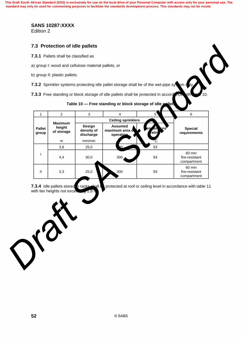
SANS 10287:XXXX Edition 2
52
7.3 Protection of idle pallets
7.3.1 Pallets shall be classified as a) group I: wood and cellulose material pallets, or b) group II: plastic pallets.
7.3.2 Sprinkler systems protecting idle pallet storage shall be of the wet-pipe system only.
7.3.3 Free standing or block storage of idle pallets shall be protected in accordance with table 10.
Table 10 — Free standing or block storage of idle pallets
1 2 3 4 5 6
Pallet group
Maximum height
of storage
Ceiling sprinklers
Special requirements
Design density of discharge
Assumed maximum area of
operation
Temperature rating
m mm/min m2 °C
I
3,8 25,0 300 93
4,4 30,0 300 93 60 min
fire-resistant compartment
II 3,3 25,0 300 93 60 min
fire-resistant compartment
7.3.4 Idle pallets stored in racks shall be protected at roof or ceiling level in accordance with table 11 with tier heights not exceeding 1,8 m.
© SABS
This Draft South African Standard (DSS) is exclusively for use on the local drive of your Personal Computer with access only for your personal use. The
standard may only be used for commenting purposes to facilitate the standards development process. This standards may not be resold.
Draft S
A Stan
dard
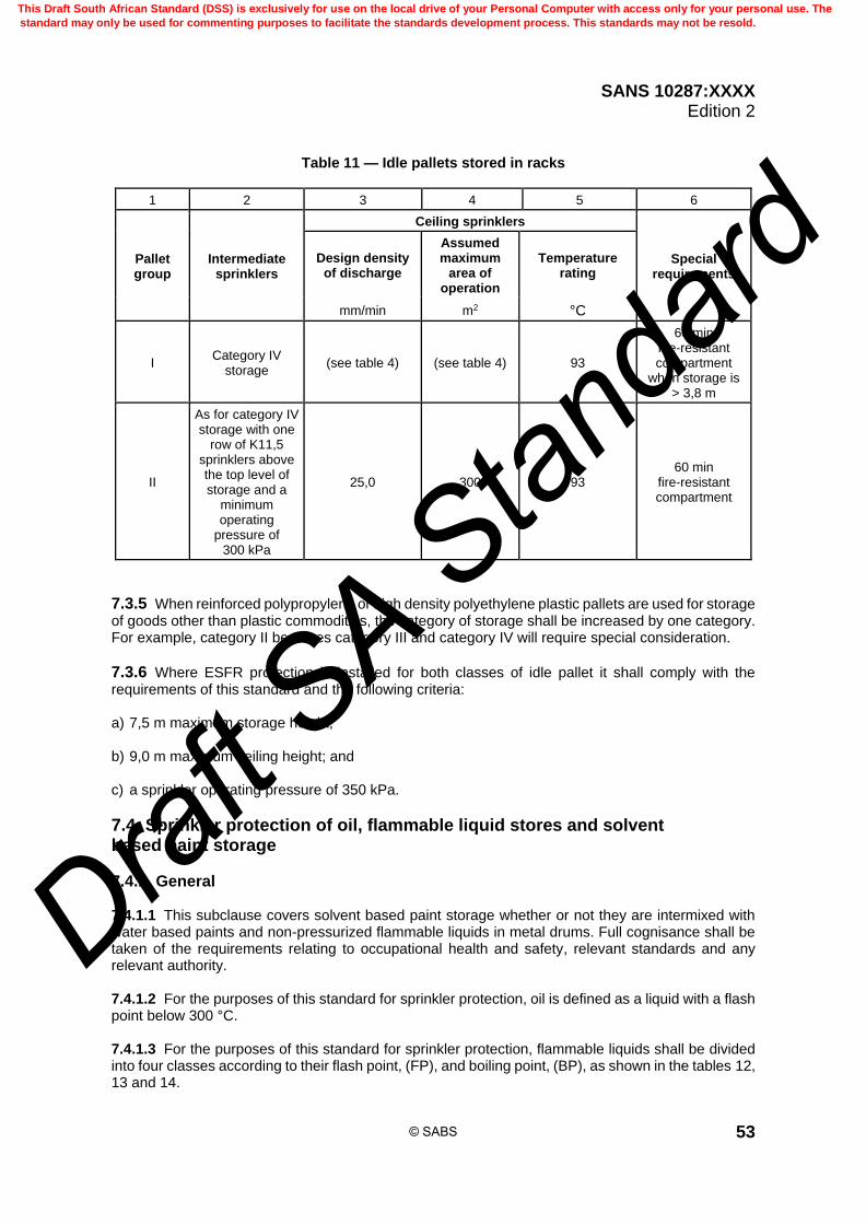
SANS 10287:XXXX Edition 2
53
Table 11 — Idle pallets stored in racks
1 2 3 4 5 6
Pallet group
Intermediate sprinklers
Ceiling sprinklers
Special requirements
Design density of discharge
Assumed maximum
area of operation
Temperature rating
mm/min m2 °C
I Category IV
storage (see table 4) (see table 4) 93
60 min fire-resistant compartment
when storage is > 3,8 m
II
As for category IV storage with one
row of K11,5 sprinklers above the top level of storage and a
minimum operating
pressure of 300 kPa
25,0 300 93 60 min
fire-resistant compartment
7.3.5 When reinforced polypropylene or high density polyethylene plastic pallets are used for storage of goods other than plastic commodities, the category of storage shall be increased by one category. For example, category II becomes category III and category IV will require special consideration.
7.3.6 Where ESFR protection is installed for both classes of idle pallet it shall comply with the requirements of this standard and the following criteria: a) 7,5 m maximum storage height; b) 9,0 m maximum ceiling height; and c) a sprinkler operating pressure of 350 kPa.
7.4 Sprinkler protection of oil, flammable liquid stores and solvent based paint storage
7.4.1 General 7.4.1.1 This subclause covers solvent based paint storage whether or not they are intermixed with water based paints and non-pressurized flammable liquids in metal drums. Full cognisance shall be taken of the requirements relating to occupational health and safety, relevant standards and any relevant authority. 7.4.1.2 For the purposes of this standard for sprinkler protection, oil is defined as a liquid with a flash point below 300 °C. 7.4.1.3 For the purposes of this standard for sprinkler protection, flammable liquids shall be divided into four classes according to their flash point, (FP), and boiling point, (BP), as shown in the tables 12, 13 and 14.
© SABS
This Draft South African Standard (DSS) is exclusively for use on the local drive of your Personal Computer with access only for your personal use. The
standard may only be used for commenting purposes to facilitate the standards development process. This standards may not be resold.
Draft S
A Stan
dard

SANS 10287:XXXX Edition 2
54
7.4.1.4 Roof or ceiling level sprinklers shall be standard response with a nominal operating temperature rating of either 93 °C or 141 °C. 7.4.1.5 Intermediate sprinklers shall be fast response with a response time index of less than 50 and a nominal operating temperature rating of 68 °C with a K-Factor of not less than 8,0. 7.4.1.6 All installations shall be installed on the wet pipe system. If a pre-action system be used, this shall be limited to a compartment size not exceeding 450 m2.
Table 12 — Free standing or block storage of flammable liquids in metal
1 2 3 4 5 6
Class Properties Drum
orientation Permitted storage
Roof or ceiling sprinklers
Design density of discharge
Assumed maximum area of
operation
°C mm/min m2
1 FP > 100 On side On end
≤ 12 drums high ≤ 6 drums high
10,0 450
2 FP ≤ 100 On side On end
≤ 6 drums high ≤ 2 drums high
25,0 450
3 FP ≤ 35a On side On end
≤ 3 drums high 1 drum high
25,0 450
4 FP ≤ 21 and
BP ≤ 35 On side or
On end 1 drum high
Deluge 25,0
Zoned
a Includes liquids where is FP ≤ 23 °C and BP is ≤ 38 °C.
Table 13 — Beam pallet racking storage of flammable liquids in
metal drums > 20 L and ≤ 208 L
1 2 3 4 5 6
Class Properties
Drum
orientationa
Permitted storage
configuration in rack
requirements
Roof or ceiling sprinklers
Design density of discharge
Assumed maximum area of
operation
°C mm/min m2
1 FP > 100 On side On end
every 12th tier every 6th tier
10,0 10,0
450 450
2 FP ≤ 100 On side On end
every 6th tier each tier
25,0 10,0
450 450
3 FP ≤ 35b On side On end
every 3rd tier each tier
25,0 10,0
450 450
4 FP ≤ 21 and
BP ≤ 35 On side or
On end
each tier Deluge
25,0
Zoned
a Drums shall be stored at a height of one drum per tier.
b Includes liquids where FP is ≤ 23 °C and BP is ≤ 38 °C.
© SABS
This Draft South African Standard (DSS) is exclusively for use on the local drive of your Personal Computer with access only for your personal use. The
standard may only be used for commenting purposes to facilitate the standards development process. This standards may not be resold.
Draft S
A Stan
dard

SANS 10287:XXXX Edition 2
55
Table 14 — Free standing, block storage, solid slatted shelf storage less than
or equal to 1,0 m in width or solid and slatted shelves over 1,0 m but less than 6,0 m in width flammable liquids in metal drums
with a capacity of 20 L
1 2 3 4 5 6
Class Properties Drum
orientation
Permitted storage height
Roof or ceiling sprinklers
Design density of discharge
Assumed maximum area of operation
°C m mm/min m2
1 FP > 100 Free standing Block storage
Shelving
5,5 5,5 4,5
7,5 7,5 10,0
450 450 450
2 FP ≤ 100 Free standing Block storage
Shelving
4,0 4,0 4,6
12,5 12,5 12,5
450 450 450
3 FP ≤ 35a
Free standing Block storage
Shelving
1,5 1,5 2,1
12,5 12,5 12,5
450 450 450
4 FP ≤ 21 and
BP ≤ 35
Free standing Block storage
Shelving
1,5 - Deluge 1,5 - Deluge 1,5 - Deluge
12,5 12,5 12,5
Zoned Zoned Zoned
a Includes liquids where FP ≤ 23 °C and BP ≤ 38 °C.
7.4.2 Intermediate sprinkler protection Sprinklers for intermediate protection and the maximum number deemed to be in simultaneous operation shall be designed in accordance with category IV requirements in accordance with this standard.
7.4.3 Foam additive
An aqueous film forming foam shall be added to the sprinkler water in accordance with the manufacturer’s recommendations. The duration of the supply shall not be less than 10 min flow equivalent to 0,5 Qmax.
7.4.4 Control of fire water run-off 7.4.4.1 Consideration shall be given to the control of fire water run-off where the release of such water may result in the damage to the environment. 7.4.4.2 In all cases an assessment of the possible environmental impact of a fire shall be carried out.
7.4.5 Zoned deluge protection The following shall be used for zoned deluge systems, as applicable: a) NFPA 15; b) NFPA 11; or c) NFPA 16.
© SABS
This Draft South African Standard (DSS) is exclusively for use on the local drive of your Personal Computer with access only for your personal use. The
standard may only be used for commenting purposes to facilitate the standards development process. This standards may not be resold.
Draft S
A Stan
dard

SANS 10287:XXXX Edition 2
56
7.5 Clothes in multiple garment hanging storage
7.5.1 General 7.5.1.1 This subclause contains specific requirements for the protection of intensive hanging garment stores having multiple rows or garment racks at two or more levels. They may have automatic or semi-automatic garment delivery, picking or transportation systems. 7.5.1.2 Access to elevated garment storage levels within the warehouse is usually by walkways and ramps. A common feature of hanging garment storage is that there is no fire separation between the decks. Walkways, aisles, ramps and garment racks create a significant obstruction to ceiling level sprinkler protection. 7.5.1.3 The standard does not cover the protection of hanging garments stored in carousels or vertical blocks without aisles. 7.5.1.4 The requirements of this standard shall be applied to all types of garments, irrespective of their storage category.
7.5.2 Sprinkler protection other than at ceiling 7.5.2.1 Sprinkler protection shall be in accordance with the requirements for intermediate sprinklers on the wet-pipe system. 7.5.2.2 Each garment rack shall be limited to two rows of hanging garments, (side by side), and a storage height of 3,5 m between intermediate levels of sprinklers. 7.5.2.3 Each rack shall be separated by an aisle of at least 0,8 m width. 7.5.2.4 The garment racks shall be protected by a single row of sprinklers. 7.5.2.5 The spacing between the sprinkler rows shall not exceed 3,0 m. 7.5.2.6 The sprinklers installed directly above the garment racks shall be stagger spaced in the vertical plane, at horizontal intervals of not more than 2,8 m along the length of the rack. 7.5.2.7 There shall be a sprinkler not more than 1,4 m from the rack end. The clearance between the top of the garments and the sprinkler deflector shall be at least 150 mm (see figure 18). 7.5.2.8 Except as modified as shown in figure 18, each sprinkler row protecting garment storage racks shall be capped by a continuous solid horizontal baffle of at least the length and width of the garment row. The baffle shall be of non-combustible construction. 7.5.2.9 The upper level of sprinkler rack protection and baffle may be omitted providing the clearance between the top of the garments and the deflectors of the ceiling sprinklers does not exceed 3,0 m height. 7.5.2.10 Sprinklers shall be installed below all access ramps, main aisles, walkways and transportation routes, with the exception of aisles, not exceeding 1,2 m wide, between sprinkler protected garment storage rows.
© SABS
This Draft South African Standard (DSS) is exclusively for use on the local drive of your Personal Computer with access only for your personal use. The
standard may only be used for commenting purposes to facilitate the standards development process. This standards may not be resold.
Draft S
A Stan
dard
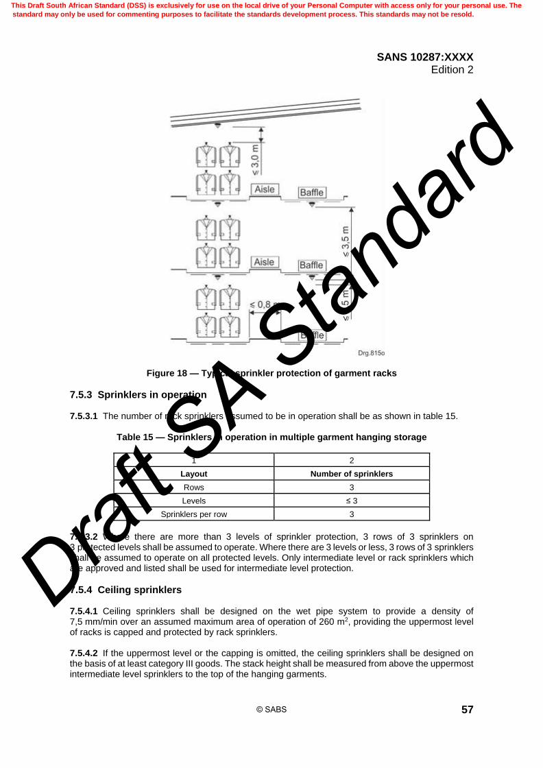
SANS 10287:XXXX Edition 2
57
Figure 18 — Typical sprinkler protection of garment racks
7.5.3 Sprinklers in operation 7.5.3.1 The number of rack sprinklers assumed to be in operation shall be as shown in table 15.
Table 15 — Sprinklers in operation in multiple garment hanging storage
1 2
Layout Number of sprinklers
Rows 3
Levels ≤ 3
Sprinklers per row 3
7.5.3.2 Where there are more than 3 levels of sprinkler protection, 3 rows of 3 sprinklers on 3 protected levels shall be assumed to operate. Where there are 3 levels or less, 3 rows of 3 sprinklers shall be assumed to operate on all protected levels. Only intermediate level or rack sprinklers which are approved and listed shall be used for intermediate level protection.
7.5.4 Ceiling sprinklers 7.5.4.1 Ceiling sprinklers shall be designed on the wet pipe system to provide a density of 7,5 mm/min over an assumed maximum area of operation of 260 m2, providing the uppermost level of racks is capped and protected by rack sprinklers. 7.5.4.2 If the uppermost level or the capping is omitted, the ceiling sprinklers shall be designed on the basis of at least category III goods. The stack height shall be measured from above the uppermost intermediate level sprinklers to the top of the hanging garments.
© SABS
This Draft South African Standard (DSS) is exclusively for use on the local drive of your Personal Computer with access only for your personal use. The
standard may only be used for commenting purposes to facilitate the standards development process. This standards may not be resold.
Draft S
A Stan
dard

SANS 10287:XXXX Edition 2
58
7.5.5 Automatic shutdown Operation of the sprinkler system shall automatically stop all automated distribution systems within the warehouse.
7.6 Non-woven synthetic fabric
7.6.1 General 7.6.1.1 Non-woven synthetic fabric is a manufactured sheet of directionally or randomly orientated fibres bonded by friction or cohesion (or both) or by cohesion or adhesion (or both). 7.6.1.2 Roof or ceiling protection shall be in accordance with table 16. 7.6.1.3 For storage heights in excess of those stated in table 16, consideration shall be given to the use of ESFR or large drop sprinkler protection.
Table 16 — Non-woven synthetic fabric storage heights
1 2 3 4
Storage configuration
Maximum permitted storage height
(see note 1)
Design density of discharge
Assumed maximum area of operation
(see note 2)
m mm/min m2
Free standing or
Block storage
1,6 10,0 260
2,0 12,5 260
2,3 15,0 260
2,7 17,5 260
3,0 20,0 300
3,3 22,5 300
3,6 25,0 300
3,8 27,5 300
4,1 30,0 300
NOTE 1 Maximum permitted storage height is the vertical distance from the floor to the sprinkler deflectors, minus 1,0 m, or the highest value shown in the table, whichever is the lower. NOTE 2 Dry and alternate installations are not permitted.
7.6.2 Rack storage 7.6.2.1 Intermediate sprinkler protection in accordance with category IV shall be used. 7.6.2.2 Roof or ceiling sprinkler protection shall have a minimum design density of discharge of 12,5 mm per minute over an assumed maximum area of operation of 260 m2.
7.7 Polypropylene or polyethylene storage bins
7.7.1 General Unless alternative approved and relevant sprinkler testing is shown, polypropylene and polyethylene storage containers shall be classed as category IV.
© SABS
This Draft South African Standard (DSS) is exclusively for use on the local drive of your Personal Computer with access only for your personal use. The
standard may only be used for commenting purposes to facilitate the standards development process. This standards may not be resold.
Draft S
A Stan
dard

SANS 10287:XXXX Edition 2
59
7.7.2 Plastic packaging recycling plants The different areas of plastic packaging recycling plants shall be protected by sprinkler or deluge systems according to the amount of combustible loading available. Pneumatic conveyor equipment may require additional protection by spark extinguishing systems. As the fire extinguishing of bulk and bale storage requires additional clearing and follow-up extinguishing measures, it is necessary to have direct alarm transmission to a permanently manned station. The protection concept shall be agreed to during the planning stage.
7.7.3 Design data of sprinkler systems for recycling plants 7.7.3.1 A sprinkler system shall be used for a) free standing or block storage, b) bale storage (compressed plastic), and c) sorting area. 7.7.3.2 The following equipment should be protected by an additional water extinguishing system (sprinkler or deluge system): a) material storage bunker; b) comminuting systems (for example shredders, mills); c) drying systems, and d) silo systems. 7.7.3.3 The maximum storage heights for bulk storage and bale storage are given in table 17 and the design data in table 18.
Table 17 — Maximum bulk and bale storage heights
1 2 3
Storage Configuration Maximum storage height
(m) Maximum room height
(m)
Bulk storage 5,0 9,0
Baled storage 4,0 9,0
Table 18 — Design data for sprinkler systems for bulk and bale storage
1 2
Design density of discharge (mm per minute) 17,5
Assumed maximum area of operation (m2) 260 (wet system) 325 (dry system)
Sprinkler sensitivity Fast response
Sprinkler temperature rating ( C) 93
Extinguishing agent Water with film forming foam
Water supply (minutes) 90
Foam supply (minutes) 60
© SABS
This Draft South African Standard (DSS) is exclusively for use on the local drive of your Personal Computer with access only for your personal use. The
standard may only be used for commenting purposes to facilitate the standards development process. This standards may not be resold.
Draft S
A Stan
dard

SANS 10287:XXXX Edition 2
60
7.7.3.4 For local protection of the equipment present in the sorting area a density of discharge of 7,5 mm/min is required. Special or quick response sprinklers shall be used. 7.7.3.5 If dry pipe systems are required for the protection of bulk and bale storage, it shall be ensured that an opening of the test fitting at the end of the pipework induces the discharge of water after 20 s at the latest.
7.7.4 Design data of deluge systems in recycling plants 7.7.4.1 A deluge system shall be used for enclosed mechanical conveyor equipment such as long belt, chain and spiral or vibratory conveyors with a density of discharge of 7,5 mm/min. 7.7.4.2 An alternative to sprinkler protection for bulk and bale storage is that these areas may be protected by a deluge system with a density of discharge of 17,5 mm/min and a proportioning of film-forming foam, provided that the storage heights are in accordance with table 17.
7.7.5 Area of operation for deluge systems (see figures 19 and 20)
Figure 19 — Area of operation of deluge systems
© SABS
This Draft South African Standard (DSS) is exclusively for use on the local drive of your Personal Computer with access only for your personal use. The
standard may only be used for commenting purposes to facilitate the standards development process. This standards may not be resold.
Draft S
A Stan
dard

SANS 10287:XXXX Edition 2
61
Figure 20 — Area of operation of deluge systems 7.7.5.1 The area protected by one deluge installation shall not be less than 100 m2 except in rooms with an area of less than 200 m2. The water supply shall be capable of supplying the total area of operation. The total area of operation shall be found by assuming a fire at the borderline between adjacent areas protected by different deluge installations. All areas are to be supplied at the same time which are touched by a radius of 7,0 m from the most unfavourable possible location of a fire. 7.7.5.2 Upon triggering of the deluge system, the conveyor and screening equipment of the appropriate area shall be disabled automatically. 7.7.5.3 The water demand for the local protection equipment in the operating areas shall be hydraulically taken into account.
7.7.6 Monitoring of sprinkler or deluge system The sprinkler deluge systems shall be monitored for operational availability.
7.7.7 Spark extinguishing systems in recycling plants A spark extinguishing system which is approved shall be used for pneumatic conveyor equipment for waste material and dust (for example, baling presses, filter systems, air separators and press waste container station).
© SABS
This Draft South African Standard (DSS) is exclusively for use on the local drive of your Personal Computer with access only for your personal use. The
standard may only be used for commenting purposes to facilitate the standards development process. This standards may not be resold.
Draft S
A Stan
dard

SANS 10287:XXXX Edition 2
62
7.7.8 Beam pallet racking for polypropylene or polyethylene storage bins 7.7.8.1 Intermediate sprinkler protection shall have a maximum horizontal spacing not exceeding 1,5 m. 7.7.8.2 The vertical spacing shall not exceed 2,0 m. 7.7.8.3 The roof or ceiling level sprinklers shall be of the fast response type with a response time index of less than 50 and shall have a nominal operating temperature rating of 93 °C. 7.7.8.4 The intermediate sprinklers shall have a K-factor of not less than 8,0 and shall be of the spray pattern type, fast response with a response time index of less than 50 with a nominal operating temperature rating of 68 °C.
7.7.9 All other storage of polypropylene or polyethylene storage bins 7.7.9.1 The maximum storage height shall not exceed 3,0 m. 7.7.9.2 Only non-combustible pallets, for example steel pallets shall be used. 7.7.9.3 The stack height per pallet shall not exceed 1,0 m and the uppermost storage container on each pallet shall be closed with a lid. 7.7.9.4 The roof or ceiling level sprinklers shall be of the fast response type with a response time index of less than 50 and shall have a nominal operating temperature rating of 93 °C.
7.8 Protection of rubber tyres
7.8.1 Storage methods 7.8.1.1 This subclause covers tyres stored horizontally, storage of tyres vertically is not covered. 7.8.1.2 The following are the different methods for tyre storage (see also figure 21): a) Banded tyre storage: a number of tyres are strapped together. b) Beam pallet racking: storage of tyres are on pallets that are stored within a typical rack framework. c) Block storage: the tyres are stored in a self-supporting pile either with vertical sides or in a pyramid
fashion for stability. d) Laced tyre storage: the sides of the tyres are stored in an overlapping pattern creating a laced
appearance. e) On side storage: the tyres are stored flat or horizontally. f) On tread tyre storage: the tyres are stored on their treads or vertically. g) Post pallet storage: pallets are stored within post pallets or stillages with either open or solid
bottoms. Tyres can be stored in the laced pattern, on side or on end within the post pallet.
7.8.2 Types of sprinkler for tyre storage 7.8.2.1 For design densities of discharge from 7,5 mm up to 12,5 mm per minute over an assumed maximum area of operation of 260 m2, standard response sprinklers with a K-factor of not less than 11,5 shall be used for the roof or ceiling level protection.
© SABS
This Draft South African Standard (DSS) is exclusively for use on the local drive of your Personal Computer with access only for your personal use. The
standard may only be used for commenting purposes to facilitate the standards development process. This standards may not be resold.
Draft S
A Stan
dard

SANS 10287:XXXX Edition 2
63
Figure 21 — Typical tyre storage methods 7.8.2.2 For design densities of discharge from 12,5 mm to 17,5 mm/min over an assumed maximum area of operation of 260 m2 and from 20,0 mm up to 30,0 mm per minute over an assumed maximum area of operation of 300 m2, standard response sprinklers with a K-factor of not less than 16,0 shall be used for the roof or ceiling level protection.
© SABS
This Draft South African Standard (DSS) is exclusively for use on the local drive of your Personal Computer with access only for your personal use. The
standard may only be used for commenting purposes to facilitate the standards development process. This standards may not be resold.
Draft S
A Stan
dard

SANS 10287:XXXX Edition 2
64
7.8.3 Columns within tyre storage areas 7.8.3.1 All building columns, if not protected by non-combustible materials with a minimum fire resistance of 2 h, shall be wetted for cooling purposes by additional sprinklers at the rate of 10,0 mm/min per square metre over one side of the surface area of the structural member. 7.8.3.2 Sprinklers shall be positioned at 4,5 m vertical intervals in order to provide uninterrupted rundown below the level of the roof or ceiling level sprinklers. 7.8.3.3 The discharge from these sprinklers within the assumed maximum area of operation shall be included in water supply and hydraulic calculation considerations. 7.8.3.4 Column protection may be omitted where ESFR protection is installed.
7.8.4 Intermediate sprinkler water demand 7.8.4.1 The pressure and flow requirements of intermediate level sprinklers shall be calculated on the assumption that the hydraulically most unfavourable sprinkler with a K-factor of not less than 8,0 operates at a pressure of not less than 200 kPa for racks and shelves when a number of sprinklers as specified in table 19 are in simultaneous operation in the hydraulically most unfavourable location
Table 19 — Number rack sprinklers in operation for rubber tyre storage
1 2 3 4
Aisle width
Number of sprinklers in simultaneous operation
m Number of sprinklers per tier level Number of tier levels Number of racks or
shelves
< 1,2 4 3 3
≥ 1,2 ≤ 2,4 4 3 2
> 2,4 4 3 1
7.8.4.2 Where only one rack is deemed to be in operation, a minimum number of 12 sprinklers shall be deemed to be in operation regardless of the number of tier levels.
7.9 Categorization of goods in storage
7.9.1 The fire hazard of stored goods is influenced by many factors such as the rate of heat release, the rate of burning and accessibility to water discharge.
7.9.2 The packaging materials and storage configuration play a major role in determining the level of sprinkler protection required.
7.9.3 To establish the level of protection required the procedure shown in the flow chart in figure 22, shall be followed.
7.10 Methodology for categorizing goods
7.10.1 General 7.10.1.1 To categorize goods containing plastic or rubber requires an analysis of the materials used, including any packaging. The result of this analysis will yield a material factor. 7.10.1.2 The storage configuration of the goods is then considered. The material factor combined with the storage configuration will determine the category of the stored goods.
© SABS
This Draft South African Standard (DSS) is exclusively for use on the local drive of your Personal Computer with access only for your personal use. The
standard may only be used for commenting purposes to facilitate the standards development process. This standards may not be resold.
Draft S
A Stan
dard

SANS 10287:XXXX Edition 2
65
7.10.1.3 In some instances the material factor number and category will be the same, but where plastics are involved the category may be higher than the material factor.
7.10.2 Material factor 7.10.2.1 A material factor of 1 to 4 shall be determined for all goods. The material factor shall take into account the product and packaging and pallet materials. 7.10.2.2 Typical materials factors are given in 7.10.3 to 7.10.6 (inclusive) and modifying influences are shown in figure 23 for material factors with plastic content.
7.10.3 Material factor 1 Non-combustible materials either without packaging or packaging with a low energy content and having a) an unexpanded plastic or rubber content less than 5 % by weight, and b) an expanded plastic or rubber content less than 5 % by volume. EXAMPLE 1 Metal parts or tools with or without cardboard packaging on wooden pallets.
EXAMPLE 2 Powdered foods in sacks.
EXAMPLE 3 Tinned or bottled foods.
EXAMPLE 4 Cloth or fabric made wholly of natural fibres.
EXAMPLE 5 Leather goods.
EXAMPLE 6 Wood products.
EXAMPLE 7 Ceramics in cardboard or wooden packing cases.
EXAMPLE 8 Non-flammable liquids in plastic, glass or waxed paper containers.
EXAMPLE 9 Large electrical appliances with little packaging.
7.10.4 Material factor 2 Goods which are potentially more difficult to sprinkler protect, with a higher energy content than in material factor 1. EXAMPLE 1 Wood or metal furniture with plastic furnishings within the allowable limits.
EXAMPLE 2 Electrical equipment with plastic parts and packaging within the allowable limits.
EXAMPLE 3 Electrical cable on reels or in cartons excluding PVC.
EXAMPLE 4 Cloth or fabric with a synthetic fibre content.
7.10.5 Material factor 3 Goods that are made predominantly of unexpanded plastic or less than 40 % expanded plastic or that have a similar energy content. EXAMPLE 1 Empty car batteries.
EXAMPLE 2 Plastic brief cases.
© SABS
This Draft South African Standard (DSS) is exclusively for use on the local drive of your Personal Computer with access only for your personal use. The
standard may only be used for commenting purposes to facilitate the standards development process. This standards may not be resold.
Draft S
A Stan
dard

SANS 10287:XXXX Edition 2
66
EXAMPLE 3 Personal computers.
EXAMPLE 4 Unexpanded plastic utensils.
7.10.6 Material factor 4 Goods with an expanded plastic or rubber content greater than 40 % by volume or materials with similar burning characteristics. EXAMPLE 1 Foam rubber mattresses.
EXAMPLE 2 Expanded polystyrene packaging.
EXAMPLE 3 Foam upholstery.
Figure 22 — Flow chart for determining the category of goods stored
7.10.7 Determining the category of stored goods using the material factor 7.10.7.1 The category of the stored goods is determined by assessing the influence of storage configuration once the material factor is known. The most appropriate goods storage configuration description shall be identified using columns 1 and 2 of table 20. 7.10.7.2 The category is given at the intersection with the appropriate material factor given in columns 3 to 6 of table 20. 7.10.7.3 If the goods are also listed in table 21 and table 22 and the category is different to that determined using the methodology, the higher of the two categories shall be used.
© SABS
This Draft South African Standard (DSS) is exclusively for use on the local drive of your Personal Computer with access only for your personal use. The
standard may only be used for commenting purposes to facilitate the standards development process. This standards may not be resold.
Draft S
A Stan
dard

SANS 10287:XXXX Edition 2
67
Table 20 — Category determination table
1 2 3 4 5 6
Storage configuration details a Material factor
Exposed surface
Stored goods
1 2 3 4
Unexpanded plastic container
Non-combustible solids and liquids which are in intimate
contact with container
Apply table 21
or table 22
II II b
Unexpanded plastic container
Non-combustible solids forming air gaps
II III b
Unexpanded plastic container
Combustible solid content II III IV
Unexpanded plastic film Non-combustible solids b b b
Unexpanded plastic film Combustible solid content II III IV
Expanded plastic Combustible or
non-combustible IV IV IV
Unexpanded plastic or rubber
Solid blocks II III IV
Paper or cardboard Plastic content II III IV
a The storage configuration details are described in greater detail within this standard.
b Material factor not appropriate to description of storage configuration (for details refer to shrink wrapped
items in 7.12.10).
Figure 23 — Material factor plastic content
© SABS
This Draft South African Standard (DSS) is exclusively for use on the local drive of your Personal Computer with access only for your personal use. The
standard may only be used for commenting purposes to facilitate the standards development process. This standards may not be resold.
Draft S
A Stan
dard

SANS 10287:XXXX Edition 2
68
Table 21 — Product categorization
1 2 3
Product or occupancy Category Comments
Abrasive wheel and powder manufacturers I –
Accumulator manufacturers (Battery) II –
Adhesives with flammable solvents warehouses
III Special protection required
Adhesives without flammable solvents warehouses
I –
Aeroplane instrument manufacturers I –
Aerosols contents and expellant flammable IV See special hazards section
Aerosols contents flammable IV See special hazards section
Aerosols contents and expellant non-flammable
I –
Aircraft engine works I –
Aircraft factories I –
Alcoholic beverages ≤ 20 % proof by volume II In metal or glass containers
Alcoholic beverages > 20 % proof by volume II Cartoned glass bottles
Ammunition – small arms IV Packaged or cartoned
Amusement grounds I Excludes amusement arcades
Appliances – for example stoves, refrigerators I Not packaged – no appreciable plastic trim
Appliances – for example stoves, refrigerators II Cartoned corrugated – no appreciable plastic trim
Appliances – for example stoves, refrigerators III No exposed expanded plastic – packaging in cardboard
Appliances – for example stoves, refrigerators III Appreciable plastic trim – no packaging
Appliances – for example stoves, refrigerators IV Exposed expanded plastic packaging and plastic trim
Artificial manure manufacturers I –
Artificial silk manufacturers II –
Artificial stone manufacturers I –
Asbestos and asbestos millboard manufacturers
I –
Asphalt paper stored horizontally II –
Asphalt paper stored vertically III –
Assayers I Gold and silver
Astronomical instruments manufacturers I –
Athletic clubs and race courses, etc. I –
Athletic goods manufacturers I Excludes clothing and wearing apparel
Automobile spare parts warehouses III and IV –
Bacon curers I –
Bakers and biscuit manufacturers I –
Baked goods II Frozen, packaged in cartons
Baked goods III Packaged in cartons
Bakelite goods manufacturers I –
Baking powder manufacturers II –
Balata belting manufacturers II –
Ballast and sand warehouses I –
Barometer manufacturers I –
© SABS
This Draft South African Standard (DSS) is exclusively for use on the local drive of your Personal Computer with access only for your personal use. The
standard may only be used for commenting purposes to facilitate the standards development process. This standards may not be resold.
Draft S
A Stan
dard
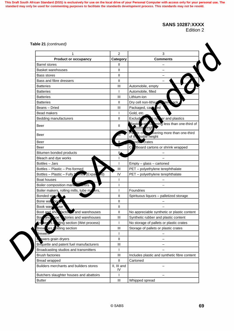
SANS 10287:XXXX Edition 2
69
Table 21 (continued)
1 2 3
Product or occupancy Category Comments
Barrel stores II –
Basket warehouses II –
Bass stores II –
Bass and fibre dressers II –
Batteries III Automobile, empty
Batteries I Automobile, filled
Batteries III Lithium-ion
Batteries II Dry cell non-lithium blister pack
Beans – Dried III Packaged, cartoned
Bead makers I Gold, etc.
Bedding manufacturers II Excluding foam rubber and plastics
Beer II Plastic crate covering less than one-third of the bottle height
Beer III Plastic crate covering more than one-third of the bottle height
Beer II Wooden crates
Beer I Cardboard cartons or shrink wrapped
Bitumen bonded products II –
Bleach and dye works I –
Bottles – Jars I Empty – glass – cartoned
Bottles – Plastic – Pre-formed III PET – polyethylene terephthalate
Bottles – Plastic – Fully formed (Expanded) IV PET – polyethylene terephthalate
Boat houses I –
Boiler composition manufacturers I –
Boiler makers, rolling mills, tube makers, I Foundries
Bonded stores II Spirituous liquors – palletized storage
Bone warehouses II –
Book warehouse II –
Boot and shoe factories and warehouses II No appreciable synthetic or plastic content
Boot and shoe factories and warehouses III Synthetic rubber and plastic content
Breweries bottling section (Wet process) I No storage of pallets or plastic crates
Breweries bottling section III Storage of pallets or plastic crates
Brewers I –
Brewers grain dryers II –
Briquette and patent fuel manufacturers III –
Broadcasting studios and transmitters I –
Brush factories III Includes plastic and synthetic fibre content
Bread wrapped II Cartoned
Builders merchants and builders stores II, III and IV
–
Butchers slaughter houses and abattoirs I –
Butter III Whipped spread
© SABS
This Draft South African Standard (DSS) is exclusively for use on the local drive of your Personal Computer with access only for your personal use. The
standard may only be used for commenting purposes to facilitate the standards development process. This standards may not be resold.
Draft S
A Stan
dard

SANS 10287:XXXX Edition 2
70
Table 21 (continued)
1 2 3
Product or occupancy Category Comments
Cable and telephone companies stores III Includes plastic content and PVC content
Cake mixture manufacturers I –
Camping equipment II No appreciable synthetic or plastic content
Candles III and IV Treat on a case by case basis
Canvas – tar impregnated III –
Carborundum manufacturers I –
Carbon black III –
Carbon paper manufacturers III –
Cardboard – All types II Stored flat
Cardboard – Except corrugated II Rolls stored horizontally
Cardboard – Except corrugated III Rolls stored vertically
Cardboard – Corrugated III Rolls stored horizontally
Cardboard – Corrugated IV Rolls stored vertically
Cardboard cartons II Empty light weight made up boxes
Cardboard cartons III Empty heavy weight made up boxes
Card clothing manufacturers I –
Carob crushing I –
Carpet beaters and cleaners I –
Carpet tiles III –
Carpets without foam backing II Intermediate rack sprinkler protection required
Carpets with foam backing III Intermediate rack sprinkler protection required
Carpets with synthetic fibre mix III Intermediate rack sprinkler protection required
Carriers and transit warehouses II, III and
IV Dependent on goods stored
Cartons – Waxed made up III –
Cartons – Waxed flat II –
Cattle food manufacturers I –
Carvers (Stone) I –
Cellulose – Not cellulose nitrate or cellulose acetate
II Baled
Cellulose pulp II –
Cement works I Includes bagged cement
Ceramics I –
Cereals boxed II –
Charcoal manufacturers II –
Cheese II Packaged and cartoned
Chemical warehouses II, III and
IV May require special consideration
Chemists (Analytical) I –
Chemists (Manufacturers and wholesale) II Assumes no appreciable plastic content
Chemical works II Ordinary – excluding flammable liquids
Chewing gum II Packaged and cartoned
© SABS
This Draft South African Standard (DSS) is exclusively for use on the local drive of your Personal Computer with access only for your personal use. The
standard may only be used for commenting purposes to facilitate the standards development process. This standards may not be resold.
Draft S
A Stan
dard

SANS 10287:XXXX Edition 2
71
Table 21 (continued)
1 2 3
Product or occupancy Category Comments
China merchants I Wholesale and warehouses
Chipboard II Not pegged
Christmas cracker manufacturers II –
Chrome platers I –
Chutney I –
Cigar and cigarette importers warehouses II –
Cloth wool or cotton II –
Cloth synthetic III –
Clothes without linings II Stored flat – assumes no synthetic fibres
Clothes foamed plastic or rubberized linings III Stored flat
Cocoa products II Packaged and cartoned
Coconut matting II –
Cod liver oil manufacturers II –
Coffee hullers and roasters II –
Coffee – Canned Beans bagged II Packaged and cartoned
Coir II Curled hair used in mattresses
Cold storage warehouses II and III Excludes EPS fabric
Colour and paint warehouses II Excludes solvent based product
Compact disks II –
Condensed milk manufacturers I –
Confectionery II –
Containers – Contents unknown III - IV Combustible containers and content treat as Category IV
Copper plate engravers I –
Copra kilns (coconut dried meat or kernel) II –
Cordials and minerals I In glass bottles
Cork factories cutters and dealers II For ordinary hazard – increase area of operation
Cork baled II For ordinary hazard – increase area of operation
Corn merchants warehouses I –
Corn, flour and provender mills I –
Corset manufacturers I –
Cotton baled II Increased area of operation required
Cotton mills I Excluding preparatory processes
Cotton warehouses II –
Cotton waste dealers warehouses III –
Creamery and wholesale dairies I –
Crockery without packaging I –
Curled hair manufacturers II –
Custard powder manufacturers I –
Creamery and wholesale dairies I –
Crockery without packaging I –
© SABS
This Draft South African Standard (DSS) is exclusively for use on the local drive of your Personal Computer with access only for your personal use. The
standard may only be used for commenting purposes to facilitate the standards development process. This standards may not be resold.
Draft S
A Stan
dard

SANS 10287:XXXX Edition 2
72
Table 21 (continued)
1 2 3
Product or occupancy Category Comments
Curled hair manufacturers II –
Custard powder manufacturers I –
Dental material and manufacturers I –
Dental material warehouses I –
Departmental stores II and III Assessment of goods stored is required
Departmental stores III Wooden furniture and foam upholstery
Diapers II Cotton or linen
Diapers – disposable III –
Drapers warehouses II Wholesale
Dried foods II Packaged and cartoned
Drysalters warehouses I –
Earthenware warehouses I –
Elastomers IV –
Electric cable warehouses II Excludes plastic insulation material
Electric cable or wire on reels III Stored in racks requires intermediate sprinklers
Electric lamp and neon light manufacturers I –
Electric wire coverers III –
Electrical dealers, wholesale, warehouses I Plastic content less than or equal to 5 % by volume
Electrical dealers, wholesale, warehouses III Plastic content more than 5 % by mass or volume
Electro platers I –
Electronic equipment with or without packaging
III Plastic content – includes computers and spares
Emery grinders I –
Emery paper cloth manufacturers I –
Empty bottles in cardboard boxes (Glass) II –
Empty bottles in cardboard boxes (Plastic) III and IV PET or similar material
Enamellers I –
Engineering Works I –
Engravers (Metal) I –
Esparto, Halfa or needle grass loose or baled III –
Fancy goods warehouses I Assumes no appreciable plastic content
Feather merchants warehouses II –
Felt manufacturers II –
Fent dealers warehouses I –
Fertilizer – Solid II May require special measures
Fertilizer – Solid II Bagged nitrates and phosphates
© SABS
This Draft South African Standard (DSS) is exclusively for use on the local drive of your Personal Computer with access only for your personal use. The
standard may only be used for commenting purposes to facilitate the standards development process. This standards may not be resold.
Draft S
A Stan
dard

SANS 10287:XXXX Edition 2
73
Table 21 (continued)
1 2 3
Product or occupancy Category Comments
Fibreboard II –
Fibreglass insulation III Paper backed rolls, bagged or unbagged
Fibre goods manufacturers and stores II –
Fibrous plaster, etc. Modellers I –
Film (Photographic) manufacturers I –
Firelighters warehouses III –
Firewood cutter and dealers II –
Fish curers I –
Fishing gear store I –
Fishing net manufacturers II –
Fish meal manufacturers II –
Fish oil manufacturers II –
Flag manufacturers I –
Flax, jute and hemp mills II Excluding preparatory processes
Flax and linen warehouses II –
Flock merchants warehouses II –
Flour in sacks or paper bags II –
Floor tiles (vinyl) IV –
Foodstuffs in sacks II –
Food – Tinned in cardboard boxes or rays I With or without plastic film wrapping
Fountain pen manufacturers II –
French polishers I –
Frozen foods: fish, meat, chicken I Non-waxed, non-plastic packaging
Frozen foods: fish, meat, chicken II Waxed paper containers – cartoned
Frozen foods: fish, meat, chicken III Plastic trays or boxes – cartoned
Fruit and vegetable I Wholesale
Fruit – dried I –
Furniture unexpanded or expanded micro cellular plastic
II –
Furniture upholstered excluding plastics II –
Furniture upholstered with foam rubber or foam plastics
III –
Furniture wooden II –
Furriers and furs II Stored flat in boxes
Galvanizers I –
Glass bevellers, cutters I –
Glass factories and warehouses I –
Glass fibre unfabricated I –
Glass manufacturers warehouses I Empty
Glass merchants I Empty
Glass paper and sand paper manufacturers I –
Glucose manufacturers I –
© SABS
This Draft South African Standard (DSS) is exclusively for use on the local drive of your Personal Computer with access only for your personal use. The
standard may only be used for commenting purposes to facilitate the standards development process. This standards may not be resold.
Draft S
A Stan
dard

SANS 10287:XXXX Edition 2
74
Table 21 (continued)
1 2 3
Product or occupancy Category Comments
Gold and silver smelters I –
Gramophone record manufacturers III Treat as plastic manufacturers
Grain II In sacks
Granaries II –
Granaries merchants warehouses II –
Grease works II –
Greasy cloth, etc. washers II –
Grindstone manufacturers I –
Grocery and provisions II, III and
IV Wholesale
Haberdashery II –
Handloom weavers I –
Hat manufacturers I –
Hay and straw dealers II –
Heald and reed heddle makers I –
Hemp warehouses II For ordinary hazard - increase area of operation
Hide warehouses I –
Hops warehouses II –
Horn and ivory merchants I –
Hose and motor belts on rhino racks II –
Hosiery factories and warehouses II –
Ice factories I –
Ironmongers warehouses (Wholesale) I –
Ivory turners I –
Jewellers warehouses I –
Jewellery factories I –
Jute warehouses II –
Keg stores I –
Knitwear – (see clothes) II, III –
Lace bleachers and dyers I –
Lace factories I –
Lace warehouses I –
© SABS
This Draft South African Standard (DSS) is exclusively for use on the local drive of your Personal Computer with access only for your personal use. The
standard may only be used for commenting purposes to facilitate the standards development process. This standards may not be resold.
Draft S
A Stan
dard

SANS 10287:XXXX Edition 2
75
Table 21 (continued)
1 2 3
Product or occupancy Category Comments
Laminated board II –
Lamp shade manufacturers I –
Lard and fat refineries II –
Laundries I –
Lead light manufacturers I –
Leather goods factories II –
Leather substitute manufacturers II –
Leather warehouses II –
Lens manufacturers and optics manufacturers I –
Lighters – Butane IV Blister packs otherwise treat as aerosols
Lime, Warehouses I –
Linen II –
Linoleum III –
Logistics warehouses III and IV –
Looking glass manufacturers I –
Luggage IV –
Magnetic tapes III –
Manchester (linen) warehouses II –
Manganese powder in drums II –
Manure merchants warehouses I –
Marble and slate works I –
Margarine works and warehouses – excludes extraction
III Up to 50 % oil – any packaging
Margarine works and warehouses – excludes extraction
IV Between 50 % and 80 % oil any packaging
Marine store dealers warehouses I –
Market gardeners I –
Matches III For ordinary hazard – increase area of operation
Mattresses II With no foam rubber or expanded plastic
Mattresses IV Limited or full foam rubber or expanded plastics
Meat II Chilled or frozen
Metal cans II Plastic shrouded or corrugated cardboard
Metal cans not shrouded I –
Margarine works and warehouses - excludes extraction
III Up to 50 % oil – any packaging
Metal goods I –
Metal workers I –
Milk powder II Bags or sacks
Mirror manufacturers I –
© SABS
This Draft South African Standard (DSS) is exclusively for use on the local drive of your Personal Computer with access only for your personal use. The
standard may only be used for commenting purposes to facilitate the standards development process. This standards may not be resold.
Draft S
A Stan
dard

SANS 10287:XXXX Edition 2
76
Table 21 (continued)
1 2 3
Product or occupancy Category Comments
Mohair I –
Monument masons I –
Motor garages I Excludes flammable liquid stores
Motor vehicle manufacturers and assembly plants
III Special consideration required
Mustard, pepper and chicory mills I –
Nail polish IV –
Natural rubber III If expanded
Nickel plating works I –
Nitrate storage II –
Nuts II Canned, cartoned or bagged
Office material and stationary suppliers III –
Oil seeds II Includes sunflower and seed husks
Oil warehouses II Flash point ≥ 300 °C excludes plastic packaging
Oil warehouses III Flash point ≥ 300 °C includes plastic packaging
Ore grinders I –
Paints water based I –
Paints (oil based) – Flash point < 32 °C IV Foam induction required – Flammable liquids
Paints (solvent-based) IV Foam induction required – Flammable liquids
Paper I Sheets stored horizontally
Paper II Sheets stored vertically
Paper weight ≤ 5 kg/100m2 III For example, Tissue paper stored horizontally
Paper weight ≤ 5 kg/100m2 IV For example, Tissue paper stored vertically
Paper weight > 5 kg/100m2 III For example, Newspaper rolls stored vertically
Paper weight > 5 kg/100m2 II For example, Newspaper rolls stored horizontally
Paper bitumen coated III –
Paper pulp II Rolled or baled
Paper waste III For ordinary hazard – increase area of operation
Paper wax coated III –
Parking basements I Special considerations in area of operation
Particle board II –
Patent flour manufacturers II –
Pea warehouses II Packaged and cartoned
Pharmaceuticals III Plastic bottles cartoned
Photographic supplies manufacturers II 35 mm in metal film cartridges and bulk film rolls
© SABS
This Draft South African Standard (DSS) is exclusively for use on the local drive of your Personal Computer with access only for your personal use. The
standard may only be used for commenting purposes to facilitate the standards development process. This standards may not be resold.
Draft S
A Stan
dard
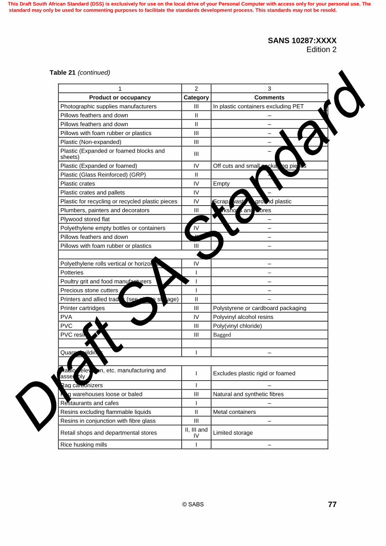
SANS 10287:XXXX Edition 2
77
Table 21 (continued)
1 2 3
Product or occupancy Category Comments
Photographic supplies manufacturers III In plastic containers excluding PET
Pillows feathers and down II –
Pillows feathers and down II –
Pillows with foam rubber or plastics III –
Plastic (Non-expanded) III –
Plastic (Expanded or foamed blocks and sheets)
III –
Plastic (Expanded or foamed) IV Off cuts and small packaging pieces
Plastic (Glass Reinforced) (GRP) II –
Plastic crates IV Empty
Plastic crates and pallets IV –
Plastic for recycling or recycled plastic pieces IV Scrap, waste or ground plastic
Plumbers, painters and decorators III Workshops and stores
Plywood stored flat II –
Polyethylene empty bottles or containers IV –
Pillows feathers and down II –
Pillows with foam rubber or plastics III –
Polyethylene rolls vertical or horizontal IV –
Potteries I –
Poultry grit and food manufacturers I –
Precious stone cutters I –
Printers and allied trades (see nitrate storage) II –
Printer cartridges III Polystyrene or cardboard packaging
PVA IV Polyvinyl alcohol resins
PVC III Poly(vinyl chloride)
PVC resins III Bagged
Quarry buildings I –
Radio, television, etc. manufacturing and assembly
I Excludes plastic rigid or foamed
Rag carbonizers I –
Rag warehouses loose or baled III Natural and synthetic fibres
Restaurants and cafes I –
Resins excluding flammable liquids II Metal containers
Resins in conjunction with fibre glass III –
Retail shops and departmental stores II, III and
IV Limited storage
Rice husking mills I –
© SABS
This Draft South African Standard (DSS) is exclusively for use on the local drive of your Personal Computer with access only for your personal use. The
standard may only be used for commenting purposes to facilitate the standards development process. This standards may not be resold.
Draft S
A Stan
dard
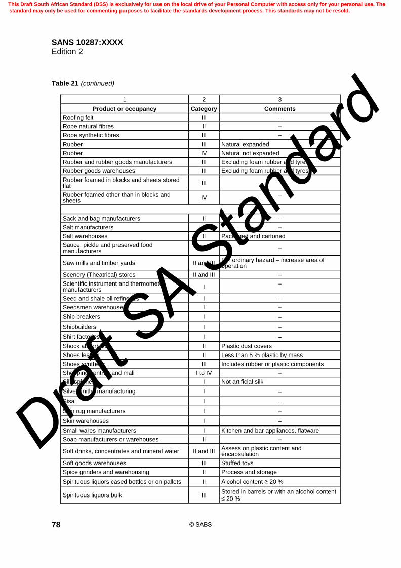
SANS 10287:XXXX Edition 2
78
Table 21 (continued)
1 2 3
Product or occupancy Category Comments
Roofing felt III –
Rope natural fibres II –
Rope synthetic fibres III –
Rubber III Natural expanded
Rubber IV Natural not expanded
Rubber and rubber goods manufacturers III Excluding foam rubber and tyres
Rubber goods warehouses III Excluding foam rubber and tyres
Rubber foamed in blocks and sheets stored flat
III –
Rubber foamed other than in blocks and sheets
IV –
Sack and bag manufacturers II –
Salt manufacturers I –
Salt warehouses II Packaged and cartoned
Sauce, pickle and preserved food manufacturers
I –
Saw mills and timber yards II and III For ordinary hazard – increase area of operation
Scenery (Theatrical) stores II and III –
Scientific instrument and thermometer manufacturers
I –
Seed and shale oil refineries I –
Seedsmen warehouses I –
Ship breakers I –
Shipbuilders I –
Shirt factories I –
Shock absorbers II Plastic dust covers
Shoes leather II Less than 5 % plastic by mass
Shoes synthetic III Includes rubber or plastic components
Shopping centres and mall I to IV –
Silk spinners I Not artificial silk
Silversmiths manufacturing I –
Sisal I –
Skin rug manufacturers I –
Skin warehouses I –
Small wares manufacturers I Kitchen and bar appliances, flatware
Soap manufacturers or warehouses II –
Soft drinks, concentrates and mineral water II and III Assess on plastic content and encapsulation
Soft goods warehouses III Stuffed toys
Spice grinders and warehousing II Process and storage
Spirituous liquors cased bottles or on pallets II Alcohol content ≥ 20 %
Spirituous liquors bulk III Stored in barrels or with an alcohol content ≤ 20 %
© SABS
This Draft South African Standard (DSS) is exclusively for use on the local drive of your Personal Computer with access only for your personal use. The
standard may only be used for commenting purposes to facilitate the standards development process. This standards may not be resold.
Draft S
A Stan
dard

SANS 10287:XXXX Edition 2
79
Table 21 (continued)
1 2 3
Product or occupancy Category Comments
Sports goods warehousing III Including sports clothing
Stables I –
Stained glass manufacturers I –
Starch works I –
Stationery and office supplies III –
Steel wool III -
Stone masons I –
Straw plait and straw hat manufacturers II –
String natural materials I –
String synthetic materials II –
Stucco manufacturers I –
Suet manufacturers I –
Sugar warehouses factories and refineries II –
Tailors' wadding manufacturers I –
Tallow warehouses II Beef or mutton fat
Tanneries I –
Tanners' warehouses and dried skins II –
Tarpaulin and tent manufacturers and warehousing
III –
Tar products roofing and bitumen products III –
Tea factories I –
Telegraph and telephone wire coverers III –
Timber un-sawn II –
Timber (sawn not in ventilated stacks) II –
Timber (sawn in ventilated stacks) III –
Tobacco bonds II –
Tobacco manufacturers II –
Tobacco warehouses II –
Tortoiseshell works II –
Toys metal I –
Toys expanded plastic III –
Toy warehouses III –
Toys wooden II –
Tripe boilers I –
Twine warehouses II –
Typewriter ribbon manufacturers II –
Tyre warehouse IV Stored horizontally – vertically is not covered
Umbrella manufacturers I –
Uralite manufacturers I –
Upholstery II Excluding foam rubber and plastics
© SABS
This Draft South African Standard (DSS) is exclusively for use on the local drive of your Personal Computer with access only for your personal use. The
standard may only be used for commenting purposes to facilitate the standards development process. This standards may not be resold.
Draft S
A Stan
dard
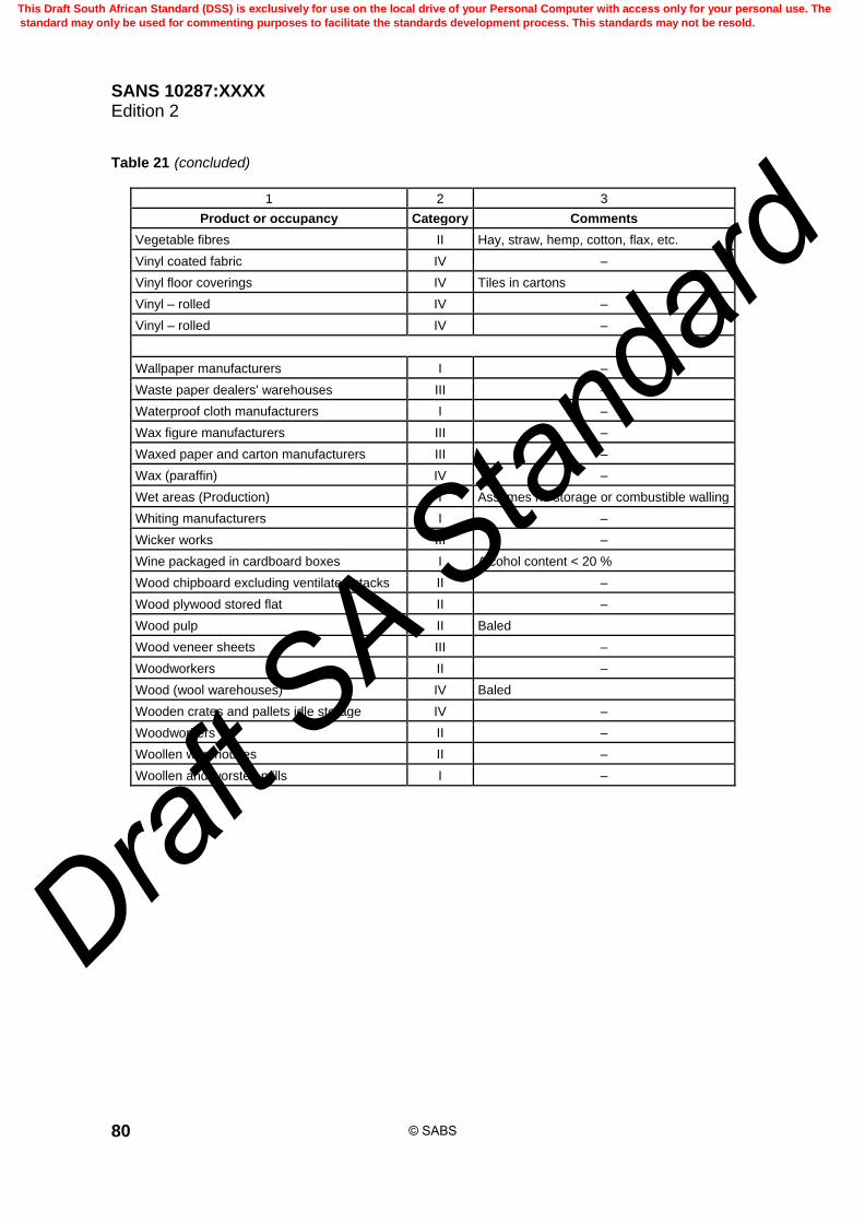
SANS 10287:XXXX Edition 2
80
Table 21 (concluded)
1 2 3
Product or occupancy Category Comments
Vegetable fibres II Hay, straw, hemp, cotton, flax, etc.
Vinyl coated fabric IV –
Vinyl floor coverings IV Tiles in cartons
Vinyl – rolled IV –
Vinyl – rolled IV –
Wallpaper manufacturers I –
Waste paper dealers' warehouses III –
Waterproof cloth manufacturers I –
Wax figure manufacturers III –
Waxed paper and carton manufacturers III –
Wax (paraffin) IV –
Wet areas (Production) I Assumes no storage or combustible walling
Whiting manufacturers I –
Wicker works III –
Wine packaged in cardboard boxes I Alcohol content < 20 %
Wood chipboard excluding ventilated stacks II –
Wood plywood stored flat II –
Wood pulp II Baled
Wood veneer sheets III –
Woodworkers II –
Wood (wool warehouses) IV Baled
Wooden crates and pallets idle storage IV –
Woodworkers II –
Woollen warehouses II –
Woollen and worsted mills I –
© SABS
This Draft South African Standard (DSS) is exclusively for use on the local drive of your Personal Computer with access only for your personal use. The
standard may only be used for commenting purposes to facilitate the standards development process. This standards may not be resold.
Draft S
A Stan
dard

SANS 10287:XXXX Edition 2
81
Table 22 — Plastics categorization
1 2 3
Product or trade name
Type of plastic Category
ABS Acrylonitrile-butadiene-styrene copolymer III
Acribel Acrylic II
Acrilan Acrylic III
Acronal Polyacrylic III
Acrylonitrile butadiene styrene resins
Acrylonitrile butadiene rubber III
Acetal and acetal resins
Polyformaldehyde III
Acrylic fibre yarn
Polymethyl methacrylate III and IV
Acrylic resins – III
Aerolite Amino I
Aerodux Formaldehyde II
Aero jablex PVC III
Akulon Nylon III
Alkathene Polythene III
Alprokyd Alkyd resin I
Alathon Polythene III
Alloprene Chlorinated rubber III
Alvar Polyvinyl acetal III
Aldehydes Formaldehydes, etc. I
Aklyd resins – I
Amberlite Phenol formaldehyde resin II
Amino plastics – II
Aniline formaldehyde
– I
Armourbex Cellulose acetate II
Araldite Epoxide II
Armoride Vinyl IV
Arlingcalf PVC coated Leather cloth III
Arlinghide PVC coated Leather cloth III
Armacord PVC coated Leather cloth III
Arnioride PVC coated Leather cloth III
Ardil fibre Protein I
Artilana No information III
Ashlam Amino I
Ashlam laminate
Amino III
ASP Phenolic II
Astralon Vinyl IV
NOTE If solvents are used with category I, classify as category III or with categories II or III classify as category IV.
© SABS
This Draft South African Standard (DSS) is exclusively for use on the local drive of your Personal Computer with access only for your personal use. The
standard may only be used for commenting purposes to facilitate the standards development process. This standards may not be resold.
Draft S
A Stan
dard

SANS 10287:XXXX Edition 2
82
Table 22 (continued)
1 2 3
Product or trade name
Type of plastic Category
Bakelite Phenolic and cresylic or polyester III
Beautide Vinyl IV
Beckacite Phenol formaldehyde I
Beckamino Amino I
Beckophen Phenolic and cresylic II
Beckosol Aklyd resin I
Bedacryl Acrylic resin III
Bedafin Alkyd I
Bedesol Phenolic and cresylic II
Beetle Alkyd or polyester resin II
Beetle U.F. Amino I
Bexan Vinyl IV
Bexfilm Cellulose acetate II
Bexform Expanded polystyrene IV
Bexoid Cellulose acetate II
Bexol Cellulose nitrate IV
Bexone Polyvinyl acetate III
Bexphane Polypropylene III
Bextrene Unexpanded polystyrene III
Breon Vinyl IV
Brulon Nylon III
Butacite Polyvinyl butyl III
Butyl rubber – III
Calaroc Alkyd I
Calatac Acrylic III
Calature Amino I
Carinex Unexpanded polystyrene III
Carlona Polythene III
Carp Phenolic and cresylic II
Cascamite Amino I
Casco-resin Amino I
Cascophan Phenolic and cresylic II
Casein Protein I
Catabond Polyester III
Catacol Phenolic and cresylic II
NOTE If solvents are used with category I, classify as category III or with categories II or III classify as category IV.
© SABS
This Draft South African Standard (DSS) is exclusively for use on the local drive of your Personal Computer with access only for your personal use. The
standard may only be used for commenting purposes to facilitate the standards development process. This standards may not be resold.
Draft S
A Stan
dard
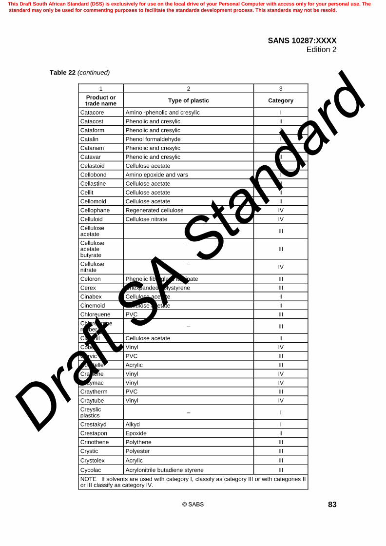
SANS 10287:XXXX Edition 2
83
Table 22 (continued)
1 2 3
Product or trade name
Type of plastic Category
Catacore Amino -phenolic and cresylic I
Catacost Phenolic and cresylic II
Cataform Phenolic and cresylic II
Catalin Phenol formaldehyde I
Catanam Phenolic and cresylic II
Catavar Phenolic and cresylic II
Celastoid Cellulose acetate II
Cellobond Amino epoxide and vars I
Cellastine Cellulose acetate II
Cellit Cellulose acetate II
Cellomold Cellulose acetate II
Cellophane Regenerated cellulose IV
Celluloid Cellulose nitrate IV
Cellulose acetate
– III
Cellulose acetate butyrate
– III
Cellulose nitrate
– IV
Celoron Phenolic fibreglass laminate III
Cerex Unexpanded polystyrene III
Cinabex Cellulose acetate II
Cinemoid Cellulose acetate II
Chloreuene PVC III
Chloroprene rubber
– III
Clarifoil Cellulose acetate II
Cobex Vinyl IV
Corvic PVC III
Courtelle Acrylic III
Craylene Vinyl IV
Craymac Vinyl IV
Craytherm PVC III
Craytube Vinyl IV
Creyslic plastics
– I
Crestakyd Alkyd I
Crestapon Epoxide II
Crinothene Polythene III
Crystic Polyester III
Crystolex Acrylic III
Cycolac Acrylonitrile butadiene styrene III
NOTE If solvents are used with category I, classify as category III or with categories II or III classify as category IV.
© SABS
This Draft South African Standard (DSS) is exclusively for use on the local drive of your Personal Computer with access only for your personal use. The
standard may only be used for commenting purposes to facilitate the standards development process. This standards may not be resold.
Draft S
A Stan
dard

SANS 10287:XXXX Edition 2
84
Table 22 (continued)
1 2 3
Product or trade name
Type of plastic Category
Delaron Amino I
Delrim Polyacetal III
Dentacryl Acrylic III
Dexel Cellulose acetate II
Dialam Phenolic and cresylic II
Diakon Acrylic II
Dichlorid PVC III
Diolen Polyester III
Diothene Polythene III
Diorid PVC III
Distrene Unexpanded polystyrene III
Dorcasine Protein I
Dralon Acrylic II
Dupraplex PVC-coated fabric III
Duranide PVC-coated fabric III
Duraplex Vinyl IV
Durex Phenolic III
Durethan Polyamide I
Dacron Polyester III
Daltolac Alkyd I
Darvic PVC III
Decorplast Amino I
Delaron Amino I
Delrim Polyacetal III
Dentacryl Acrylic III
Dexel Cellulose acetate II
Dialam Phenolic and cresylic II
Diakon Acrylic II
Dichlorid PVC III
Diolen Polyester III
Diothene Polythene III
Diorid PVC III
Distrene Unexpanded polystyrene III
Dorcasine Protein I
Dralon Acrylic II
NOTE If solvents are used with category I, classify as category III or with categories II or III classify as category IV.
© SABS
This Draft South African Standard (DSS) is exclusively for use on the local drive of your Personal Computer with access only for your personal use. The
standard may only be used for commenting purposes to facilitate the standards development process. This standards may not be resold.
Draft S
A Stan
dard

SANS 10287:XXXX Edition 2
85
Table 22 (continued)
1 2 3
Product or trade name
Type of plastic Category
Dupraplex PVC-coated fabric III
Duranide PVC-coated fabric III
Duraplex Vinyl IV
Durex Phenolic III
Durethan Polyamide I
Durotube PVC III
Durrna Vinyl IV
Dylan Polythene III
Dylene Unexpanded polystyrene III
ECTFE Ethylene-chlorotrifluoro-ethylene copolymer IV
EPDM Ethylene-propylene rubber III
ETFE Ethylene-tetrafluoroethylene copolymer IV
Eanplast Cellulose acetate II
Ecarit Cellulose acetate II
Elo Phenolic and cresylic II
Elvax Vinyl IV
Emitape Cellulose acetate II
Empire Laminated glass fibre-silicone resin III
Enkalon Polyamide I
Epikote Thermosetting resin – no other information II
Epok Alkyd amino I
Epopher Epoxide II
Epoxy or Epoxide resins
– II
Erinite Phenol formaldehyde I
Erinofort Cellulose acetate II
Erinoid Cellulose acetate II
Erinoid Unexpanded polystyrene III
Ethocel Ethyl cellulose II
Ethyl cellulose – III
Everex Polythene III
Everflex PVC-coated fabric III
Expanded plastics
– IV
Exton Nylon III
NOTE If solvents are used with category I, classify as category III or with categories II or III classify as category IV.
© SABS
This Draft South African Standard (DSS) is exclusively for use on the local drive of your Personal Computer with access only for your personal use. The
standard may only be used for commenting purposes to facilitate the standards development process. This standards may not be resold.
Draft S
A Stan
dard

SANS 10287:XXXX Edition 2
86
Table 22 (continued)
1 2 3
Product or trade name
Type of plastic Category
FEP Fluorinated ethylene-propylene copolymer IV
FRP Fibreglass reinforced polyester III
Fablon PVC coated fabric III
Fablothene Polythene III
Featalak Amino I
Featasol Alkyd I
Fibestos Cellulose acetate II
Fibravil Vinyl IV
Fibreglass – III
Filabond Polyester III
Finapic Phenolic and cresylic II
Florafoam PVC-foam fabric IV
Florestin PVC-coated fabric III
Fluon Polytetrafluoroethylene I
Flurocarbons – I
Fluoroplastics – IV
Foampac Urea formaldehyde foam IV
Foam plastics – IV
Formaldehyde plastics
– I
Formapex Phenolic and cresylic II
Formica Phenol formaldehyde III
Formica laminates
Phenol formaldehyde III
Formite Phenolic and cresylic II
Formvar Vinyl IV
Foam plastics – IV
Forticel Cellulose acetate II
Fromocene Vinyl IV
Fromoplas Vinyl IV
Fromosan Vinyl IV
Fromotan Vinyl IV
Fromotex PVC-coated fabric III
NOTE If solvents are used with category I, classify as category III or with categories II or III classify as category IV.
© SABS
This Draft South African Standard (DSS) is exclusively for use on the local drive of your Personal Computer with access only for your personal use. The
standard may only be used for commenting purposes to facilitate the standards development process. This standards may not be resold.
Draft S
A Stan
dard

SANS 10287:XXXX Edition 2
87
Table 22 (continued)
1 2 3
Product or trade name
Type of plastic Category
Gelva Polyvinyl acetate III
Geon PVC III
Geon 101 PVC III
Geon 200 Vinyl chloride III
Grilon Polyamide I
Guttasya PVC III
Harcose C Cellulose acetate II
HDPE High density polyethylene IV
Holoplast Phenolic and cresylic II
Holoplast laminate
Phenolic and cresylic II
Hornblend Amino I
Hostaflon C Polytrifluorochloroethylene I
Hostaflon T.F. Polytetrafluoroethylene I
Hostalen C Polythene III
Hostalen P.P. Polypropylene III
Harcose C Cellulose acetate II
Hostalit PVC III
Igelit PVC III
Insmat Phenolic and cresylic II
Isoflex Cellulose acetate II
Isolene Butylene polymer II
Jectothane Polyurethane II
Kabroloid Cellulose acetate II
Kallodent Polymethyl methacrylate II
Kallodoc Acrylic II
Keebush Phenol formaldehyde I
Kel – F Polytrifluorochloroethylene I
Kematal Acetal copolymer II
Kite Phenolic and cresylic II
Kodaloid Cellulose nitrate IV
Kodapak Cellulose acetate II
Kallodoc Acrylic II
Kollecast Phenolic and cresylic II
Kralastic Acrylonitrile butadiene styrene III
NOTE If solvents are used with category I, classify as category III or with categories II or III classify as category IV.
© SABS
This Draft South African Standard (DSS) is exclusively for use on the local drive of your Personal Computer with access only for your personal use. The
standard may only be used for commenting purposes to facilitate the standards development process. This standards may not be resold.
Draft S
A Stan
dard

SANS 10287:XXXX Edition 2
88
Table 22 (continued)
1 2 3
Product or trade name
Type of plastic Category
Lacisana Protein – Casein I
Lectofil Protein – Casein I
Lactoid Protein – Casein I
Lamalac Laminated III
Laminac Polyester III
Laminated plastics
– III
Lanital Protein – Casein I
Lansil Cellulose acetate II
Lanusa Viscose – Rayon III
Lauxite Phenolic and cresylic II
Layflat Polythene III
Leguval Polyester III
Lexan Polycarbonate I
Loanlin Unexpanded polystyrene III
Lorival Phenolic and cresylic II
Lorival Polythene III
Lorival Vinyl IV
Lucentine Styrene/Devinyl benzene copolymer III
Lucite Polymethyl methacrylate II
Lumarith Cellulose acetate II
Luran Unexpanded polystyrene III
Luron Polyamide I
Lustrette PVC-coated fabric III
Lustrex Unexpanded polystyrene III
Lustron Unexpanded polystyrene III
Lyafol Polyamide I
Lypolene Polythene III
Macite Cellulose acetate II
Makalot Phenolic I
Marco Polyester III
Marcon Polyester III
Marlex Olefin polymer (No information – treat as) III
Malamine Melamine formaldehyde IV
Melloroid PVC-coated fabric III
NOTE If solvents are used with category I, classify as category III or with categories II or III classify as category IV.
© SABS
This Draft South African Standard (DSS) is exclusively for use on the local drive of your Personal Computer with access only for your personal use. The
standard may only be used for commenting purposes to facilitate the standards development process. This standards may not be resold.
Draft S
A Stan
dard

SANS 10287:XXXX Edition 2
89
Table 22 (continued)
1 2 3
Product or trade name
Type of plastic Category
Melinex Polyester III
Melmex Melamine formaldehyde I
Melplas Cellulose acetate II
Methocel Methyl cellulose III
Micanite Laminated glass fabric – silicone resin III
Micor Phenolic and cresylic II
Movil Vinyl IV
Moltopren Polyester and polyether foam IV
Mouldrite Phenolic and cresylic II
Montopore Unexpanded polystyrene III
Mylar Polyester III
Nestor Amino I
Nestorite Amino I
Netlon Thermoplastic (No information – treat as) III
Nitron Cellulose acetate II
Nixonite Cellulose acetate II
Northproof PVC-coated fabric III
Nouellon Cellulose acetate II
Novilon Asbestos tile with PVC face II
Nuron Polyester III
Nylaf Polyamide II
Nylon Polyamide – Nylon 6 – Nylon 6/6 IV
Onazote Expanded ebonite IV
Oppanol Polyisobutylene (No information – treat as) III
Orlon Acrylic II
Panilax Aniline formaldehyde I
Panilax laminate
Aniline formaldehyde III
Paralac Alkyd and amino I
Paxolen Phenolic and cresylic II
Paxolin Amino I
Paxolin laminate
– III
PCTFE Polychlorotrifluoroethylene IV
Pe-Ce Vinyl IV
NOTE If solvents are used with category I, classify as category III or with categories II or III classify as category IV.
© SABS
This Draft South African Standard (DSS) is exclusively for use on the local drive of your Personal Computer with access only for your personal use. The
standard may only be used for commenting purposes to facilitate the standards development process. This standards may not be resold.
Draft S
A Stan
dard

SANS 10287:XXXX Edition 2
90
Table 22 (continued)
1 2 3
Product or trade name
Type of plastic Category
Penton Chlorinated polyether III
PET Polyethylene terephthalate III
Perlon Polyamide I
Permali Phenolic and cresylic II
Permawood Phenolic and cresylic II
Perspex Acrylic II
Phenco PVC III
Phenolic – IV
Phenrib Vinyl IV
Phoenmark Vinyl II
Plaskon Urea formaldehyde I
Plastacele Cellulose acetate III
Plastokyd Alkyd and amino I
Plasoco PVC-coated fabric III
Plasvic Vinyl IV
Plaxide PVC-coated fabric III
Plexiglass Polymethyl methacrylate II
Polana Protein – Casein I
Polyamides – I
Polycarbonate – I
Polyester resins – III
Polyethylene – III
Polygram Phenol formaldehyde I
Polypropylene III
Polystyrene Not foam III
Polystyrene Foamed IV
Polythene – III
Polyvinyl Vinyl – excluding PVC IV
Poly(vinyl)chlori-de)
PVC – plasticiser content up to 20 % III
Poly(vinyl)chlori-de)
PVC – plasticiser content greater than 20 % IV
Polyzote Unexpanded polystyrene III
Polyurethane not foam II
Polyurethane foamed III
NOTE If solvents are used with category I, classify as category III or with categories II or III classify as category IV.
© SABS
This Draft South African Standard (DSS) is exclusively for use on the local drive of your Personal Computer with access only for your personal use. The
standard may only be used for commenting purposes to facilitate the standards development process. This standards may not be resold.
Draft S
A Stan
dard

SANS 10287:XXXX Edition 2
91
Table 22 (continued)
1 2 3
Product or trade name
Type of plastic Category
Polyester yarn Includes polyester elastomer III
PTFE Polytetrafluoroethylene IV
Portex Acrylic II
Portex Polyamide or polythene III
Porvic PVC III
Propathene Polypropylene III
Protein resins – I
Prystal Phenol formaldehyde I
Pyalin Cellulose nitrate IV
Reinforced plastics
– III
Rooplex Polyester III
Resinox Phonolic I
Resolite Amino I
Rhodoid Cellulose acetate II
Rhovil Vinyl IV
Rigidox Polythene III
Rilboard Vinyl IV
Rilcom PVC III
Rilene Vinyl IV
Rilford Vinyl IV
Rilica Amino I
Rilmould Vinyl IV
Rilon PVC III
Rilotex PVC III
Rilplate Vinyl IV
Rilpol Vinyl IV
Rilsan Polyamide I
Rockite Amino I
Saran PVC III
Saroy Unexpanded polystyrene III
Scarab Amino I
Schwarza Viscose rayon III
NOTE If solvents are used with category I, classify as category III or with categories II or III classify as category IV.
© SABS
This Draft South African Standard (DSS) is exclusively for use on the local drive of your Personal Computer with access only for your personal use. The
standard may only be used for commenting purposes to facilitate the standards development process. This standards may not be resold.
Draft S
A Stan
dard

SANS 10287:XXXX Edition 2
92
Table 22 (continued)
1 2 3
Product or trade name
Type of plastic Category
Silicones Excluding rubbers I
Silicone rubber – IV
Silon Polyamide I
Silopex Laminated glass fabric – Silicone resin III
Spauldite Laminated phenolic III
Stellon Methyl methacrylate polymer III
Sternite Phenolic and cresylic II
Storain Vinyl IV
Storaya Vinyl IV
Storeen Vinyl IV
Storide PVC-coated fabric III
Storolan Vinyl IV
Storvic Vinyl IV
Stryaloy 22 Unexpanded polystyrene III
Stymer Unexpanded polystyrene III
Stryafoil Unexpanded polystyrene III
Styramic Unexpanded polystyrene III
Styroflex Unexpanded polystyrene III
Styropor Unexpanded polystyrene III
Styron Unexpanded polystyrene III
Superlom PVC-coated fabric III
Superlon Vinyl IV
Supertone Amino I
Sutron Polyamide I
Survon Polyamide I
Swan Phenolic and cresylic II
Synphorm Phenolic and cresylic II
Sytron Unexpanded polystyrene III
Teca Viscose rayon III
Tedlar Polyvinyl fluoride III
Teflon Polytetrafluoroethylene II
Tego Phenol formaldehyde I
Teklan Acrylic II
Telcothene Polythene III
Tenaplas PVC III
NOTE If solvents are used with category I, classify as category III or with categories II or III classify as category IV.
© SABS
This Draft South African Standard (DSS) is exclusively for use on the local drive of your Personal Computer with access only for your personal use. The
standard may only be used for commenting purposes to facilitate the standards development process. This standards may not be resold.
Draft S
A Stan
dard

SANS 10287:XXXX Edition 2
93
Table 22 (continued)
1 2 3
Product or trade name
Type of plastic Category
Tenasco Viscose rayon III
Tenatube PVC III
Tenite Cellulose acetate III
Tenite I Cellulose acetate III
Tenite II Cellulose acetate III
Tergal Polyester III
Terlonka Polyester III
Terylene Polyester III
Texolex Phenolic and cresylic II
Termovyl Vinyl IV
Thor Amino I
Tiolan Protein-Casein I
T.P.X. No information III
Traffolite Laminated plastic III
Traffolyte Amino I
Transpex I Polymethyl methacrylate II
Transpex II Unexpanded polystyrene III
Trevira Polyester III
Trolit B Cellulose acetate II
Trolit W Cellulose acetate II
Trolit F Cellulose nitrate IV
Trolitul Unexpanded polystyrene III
Tufnol Laminated plastic - no details III
Tulox T.T. Cellulose acetate utyrate II
Tygan Polyvinylidene chloride III
Umaplex Acrylic II
Ultramide Polyamide I
Undulite Polyester III
Utilex Cellulose acetate II
Urea Amino I
Urea Urea formaldehyde IV
Velbex Vinyl IV
Videne Polyethylene III
Vinagel PVC III
Vinalak Acrylic II
NOTE If solvents are used with category I, classify as category III or with categories II or III classify as category IV.
© SABS
This Draft South African Standard (DSS) is exclusively for use on the local drive of your Personal Computer with access only for your personal use. The
standard may only be used for commenting purposes to facilitate the standards development process. This standards may not be resold.
Draft S
A Stan
dard

SANS 10287:XXXX Edition 2
94
Table 22 (concluded)
1 2 3
Product or trade name
Type of plastic Category
Vinamold Vinyl IV
Vinamul Acrylic II
Vinatex PVC III
Vinco PVC-coated fabric III
Vinidur PVC III
Vinifoil PVC III
Vinnol PVC III
Vinylite Vinyl chloride vinyl acetate copolymer IV
Vinyon Vinyl chloride vinyl acetate copolymer IV
Vistanex Polyisobutylene III
Vistralan Cellulose rayon III
Visqueen Polythene III
Vitel Polyethylene III
Vistrathene Polythene III
Vitrite Amino I
Vitrone Vinyl IV
Vole Phenolic and cresylic II
Vuepak Cellulose acetate II
Vulcoplas Polysulphide III
Vybak PVC III
Vybax Vinyl IV
Vykem Vinyl IV
Vynide PVC-coated fabric III
Wareite Amino I
Welvic PVC III
Whale Phenolic and cresylic II
Wireweld Cellulose acetate II
Xylonite Cellulose nitrate IV
Zopide PVC-coated fabric III
Zytel Polyamide – Nylon III
NOTE If solvents are used with category I, classify as category III or with categories II or III classify as category IV.
7.10.8 Exposed unexpanded plastic container with non-combustible solids and liquids which are in intimate contact with the containers 7.10.8.1 This description applies to containers which hold non-flammable liquids or solids which are in direct contact with a high proportion of the internal container surfaces. It does not include metal
© SABS
This Draft South African Standard (DSS) is exclusively for use on the local drive of your Personal Computer with access only for your personal use. The
standard may only be used for commenting purposes to facilitate the standards development process. This standards may not be resold.
Draft S
A Stan
dard

SANS 10287:XXXX Edition 2
95
components in storage bins or boxes. Exposed unexpanded plastic container with non-combustible solids and liquids which are in intimate contact with the containers shall be classified as follows: a) containers with non-combustible liquids: category I; b) small containers (≤ 50 L) with non-combustible solids: category II; and c) large containers (> 50 L) with non-combustible solids: category III. EXAMPLE Plastic bottles of soft drinks or liquids with less than 20 % alcohol and plastic drums containing inert powder such as talcum.
7.10.8.2 Non-combustible materials in plastic containers provide a heat sink and modify the rate of burning of the containers. Liquids usually have a greater effect than solids due to their greater thermal conductivity.
7.10.9 Exposed unexpanded plastic container with non-combustible solids with air gaps This applies to plastic containers in which the contents have little or no heat sink effect. If the contact area between the container and the contents is small, (≤ 25 % of the potential storage envelope), category III ratings shall be increased to category IV. EXAMPLE Metal parts in plastic storage bins.
7.10.10 Unexpanded plastic film covering non-combustible solids 7.10.10.1 These commodities only have a small proportion of plastic by weight (in the plastic wrapping, usually < 5 %) and hence no categories are given for material factors 2, 3 and 4. EXAMPLE Shrink wrapped tinned foods.
7.10.10.2 In a fire, the plastic film is likely to burn rapidly and accelerate the fire spread. Where the packaging and the stored goods are combustible and shrink wrapped or wrapped in plastic film, the category of storage shall be increased by 1. 7.10.10.3 Where shrink wrap is used for the sides of pallet loads leaving the top of the goods stored exposed in order to provide stability the category of product need not be adjusted.
7.10.11 Unexpanded plastic film covering combustible solids 7.10.11.1 Combustible solids may contain plastic and are hence given categories for material factors 1 to 4. 7.10.11.2 In a fire the plastic film is likely to burn rapidly and accelerates the fire spread.
7.10.12 Exposed expanded plastic Exposed expanded plastics are more challenging than expanded plastic in non-plastic containers and are classified as category IV.
7.10.13 Exposed unexpanded rubber, vinyl or plastic in solid blocks Unexpanded materials in solid blocks burn at a slower rate than the same materials with higher surface area to volume and mass ratios. EXAMPLE Vinyl floor tiles.
© SABS
This Draft South African Standard (DSS) is exclusively for use on the local drive of your Personal Computer with access only for your personal use. The
standard may only be used for commenting purposes to facilitate the standards development process. This standards may not be resold.
Draft S
A Stan
dard
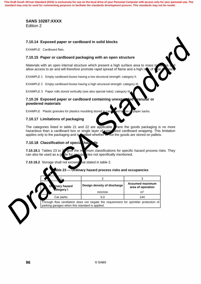
SANS 10287:XXXX Edition 2
96
7.10.14 Exposed paper or cardboard in solid blocks EXAMPLE Cardboard flats.
7.10.15 Paper or cardboard packaging with an open structure Materials with an open internal structure which present a high surface area to mass to flames and allow access to air and will therefore promote rapid spread of flame and a high rate of heat release. EXAMPLE 1 Empty cardboard boxes having a low structural strength: category II.
EXAMPLE 2 Empty cardboard boxes having a high structural strength: category III.
EXAMPLE 3 Paper rolls stored vertically (see also special risks): category III.
7.10.16 Exposed paper or cardboard containing unexpanded granular or powdered materials EXAMPLE Plastic granules for plastics moulding stored in cardboard boxes or paper sacks.
7.10.17 Limitations of packaging The categories listed in table 21 and 22 are applicable where the goods packaging is no more hazardous than a cardboard box or single layer of corrugated cardboard wrapping. This limitation applies only to the packaging and is applied whether or not the goods are stored on pallets.
7.10.18 Classification of special hazards 7.10.18.1 Tables 23 to 30 give the minimum classifications for specific hazard process risks. They can also be used as a guide for occupancies not specifically mentioned. 7.10.18.2 Storage shall not exceed that stated in table 2.
Table 23 — Ordinary hazard process risks and occupancies
1 2 3
Ordinary hazard category I
Design density of discharge Assumed maximum
area of operation
mm/min m2
Car parks 5,0 144
Through flow ventilation does not negate the requirement for sprinkler protection of parking garages when this standard is applied.
© SABS
This Draft South African Standard (DSS) is exclusively for use on the local drive of your Personal Computer with access only for your personal use. The
standard may only be used for commenting purposes to facilitate the standards development process. This standards may not be resold.
Draft S
A Stan
dard
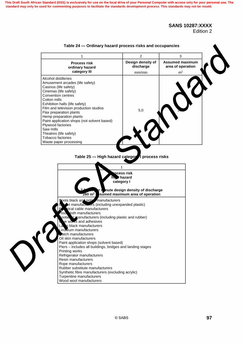
SANS 10287:XXXX Edition 2
97
Table 24 — Ordinary hazard process risks and occupancies
1 2 3
Process risk ordinary hazard
category III
Design density of discharge
Assumed maximum area of operation
mm/min m2
Alcohol distilleries Amusement arcades (life safety) Casinos (life safety) Cinemas (life safety) Convention centres Cotton mills Exhibition halls (life safety) Film and television production studios Flax preparation plants Hemp preparation plants Paint application shops (not solvent based) Plywood factories Saw mills Theatres (life safety) Tobacco factories Waste paper processing
5,0 360
Table 25 — High hazard category I process risks
1
Process risk high hazard category I
7,5 mm per minute design density of discharge
260 m2 assumed maximum area of operation
Boots black and polish manufacturers Carpet manufacturers (including unexpanded plastic) Electrical cable manufacturers Floor cloth manufacturers Footwear manufacturers (including plastic and rubber) Glue works and adhesives Lamp black manufacturers Linoleum manufacturers Match manufacturers Oil skin manufacturers Paint application shops (solvent based) Piers – includes all buildings, bridges and landing stages Printing works Refrigerator manufacturers Resin manufacturers Rope manufacturers Rubber substitute manufacturers Synthetic fibre manufacturers (excluding acrylic) Turpentine manufacturers Wood wool manufacturers
© SABS
This Draft South African Standard (DSS) is exclusively for use on the local drive of your Personal Computer with access only for your personal use. The
standard may only be used for commenting purposes to facilitate the standards development process. This standards may not be resold.
Draft S
A Stan
dard
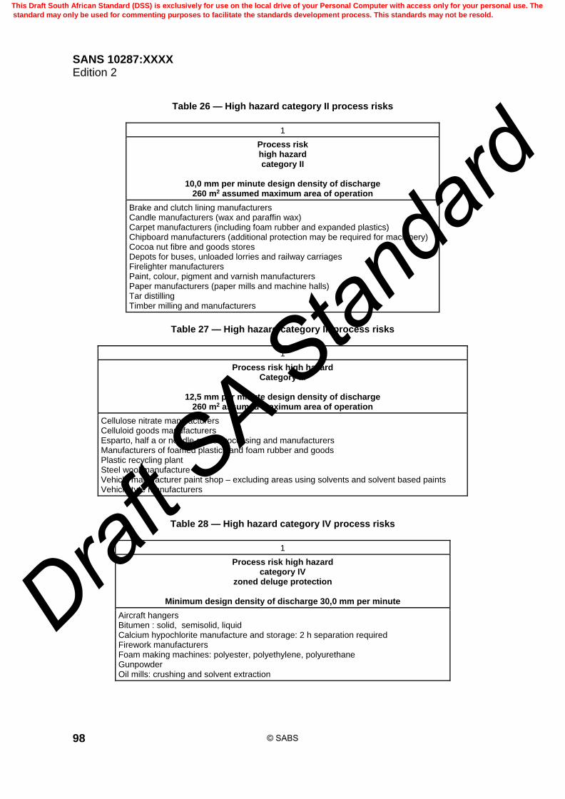
SANS 10287:XXXX Edition 2
98
Table 26 — High hazard category II process risks
1
Process risk high hazard category II
10,0 mm per minute design density of discharge
260 m2 assumed maximum area of operation
Brake and clutch lining manufacturers Candle manufacturers (wax and paraffin wax) Carpet manufacturers (including foam rubber and expanded plastics) Chipboard manufacturers (additional protection may be required for machinery) Cocoa nut fibre and goods stores Depots for buses, unloaded lorries and railway carriages Firelighter manufacturers Paint, colour, pigment and varnish manufacturers Paper manufacturers (paper mills and machine halls) Tar distilling Timber milling and manufacturers
Table 27 — High hazard category III process risks
1
Process risk high hazard Category III
12,5 mm per minute design density of discharge
260 m2 assumed maximum area of operation
Cellulose nitrate manufacturers Celluloid goods manufacturers Esparto, half a or needle grass processing and manufacturers Manufacturers of foamed plastics and foam rubber and goods Plastic recycling plant Steel wool manufacture Vehicle manufacturer paint shop – excluding areas using solvents and solvent based paints Vehicle tyre manufacturers
Table 28 — High hazard category IV process risks
1
Process risk high hazard category IV
zoned deluge protection
Minimum design density of discharge 30,0 mm per minute
Aircraft hangers Bitumen : solid, semisolid, liquid Calcium hypochlorite manufacture and storage: 2 h separation required Firework manufacturers Foam making machines: polyester, polyethylene, polyurethane Gunpowder Oil mills: crushing and solvent extraction
© SABS
This Draft South African Standard (DSS) is exclusively for use on the local drive of your Personal Computer with access only for your personal use. The
standard may only be used for commenting purposes to facilitate the standards development process. This standards may not be resold.
Draft S
A Stan
dard
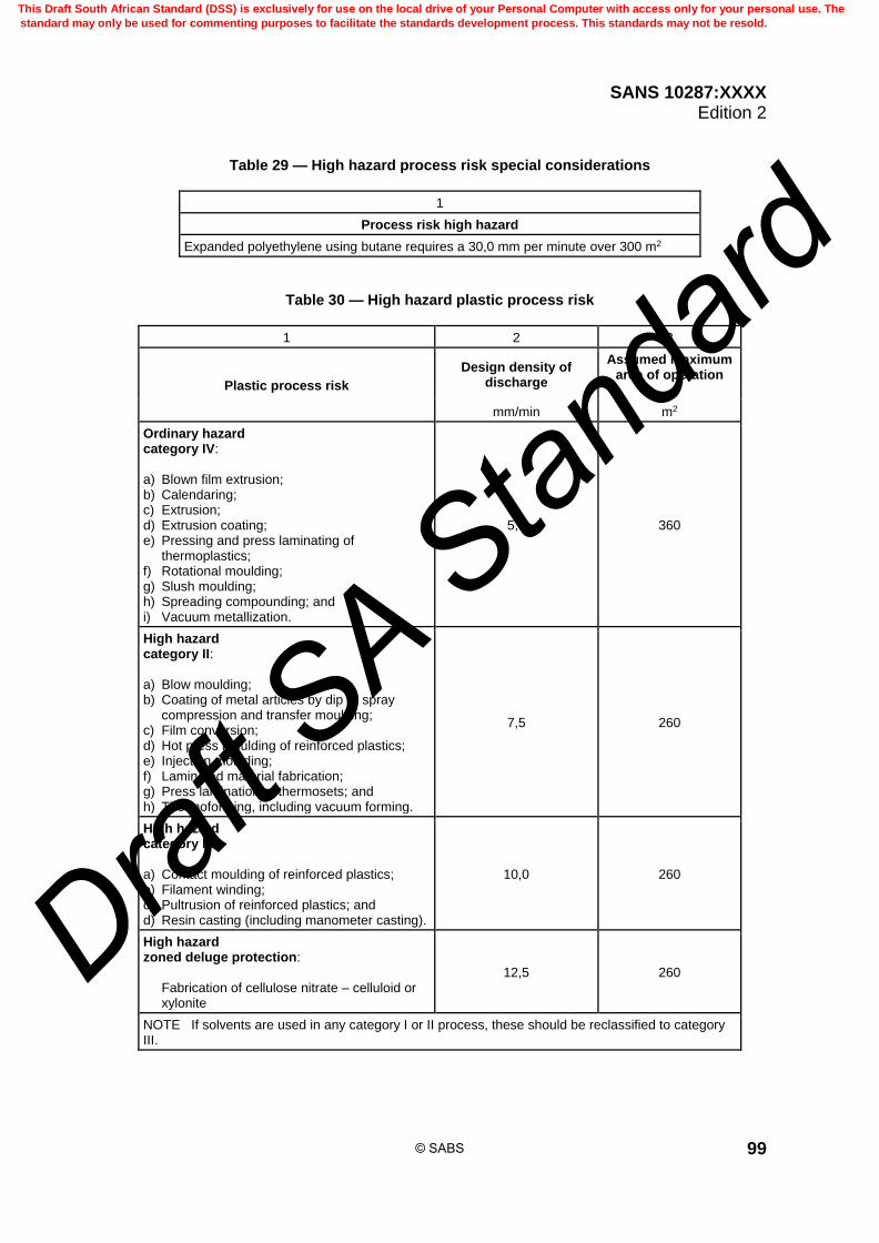
SANS 10287:XXXX Edition 2
99
Table 29 — High hazard process risk special considerations
1
Process risk high hazard
Expanded polyethylene using butane requires a 30,0 mm per minute over 300 m2
Table 30 — High hazard plastic process risk
1 2 3
Plastic process risk
Design density of discharge
Assumed maximum area of operation
mm/min m2
Ordinary hazard category IV: a) Blown film extrusion; b) Calendaring; c) Extrusion; d) Extrusion coating; e) Pressing and press laminating of
thermoplastics; f) Rotational moulding; g) Slush moulding; h) Spreading compounding; and i) Vacuum metallization.
5,0 360
High hazard category II: a) Blow moulding; b) Coating of metal articles by dip or spray
compression and transfer moulding; c) Film conversion; d) Hot press moulding of reinforced plastics; e) Injection moulding; f) Laminated material fabrication; g) Press lamination of thermosets; and h) Thermoforming, including vacuum forming.
7,5 260
High hazard category III: a) Contact moulding of reinforced plastics; b) Filament winding; c) Pultrusion of reinforced plastics; and d) Resin casting (including manometer casting).
10,0 260
High hazard zoned deluge protection: Fabrication of cellulose nitrate – celluloid or
xylonite
12,5 260
NOTE If solvents are used in any category I or II process, these should be reclassified to category III.
© SABS
This Draft South African Standard (DSS) is exclusively for use on the local drive of your Personal Computer with access only for your personal use. The
standard may only be used for commenting purposes to facilitate the standards development process. This standards may not be resold.
Draft S
A Stan
dard

SANS 10287:XXXX Edition 2
100
7.10.19 General storage categorization The lists of items for categorization are not exhaustive and it shall be assumed that items of storage not specifically mentioned are regarded automatically as in doubt whereby external consultation will be required.
7.10.20 Fire retardants NOTE The use of fire retardants does not change the category of storage.
7.10.21 Retail and wholesale outlets 7.10.21.1 Care shall be taken when categorizing retail and wholesale outlets whether or not these are standalone structures or incorporated into shopping centres. The highest hazard dictates the overall protection that will be required which is generally found to be category III. 7.10.21.2 Where a retail outlet on the floor or selling area utilizes picking shelves only, the classification of the occupancy shall be based on the height of storage against the highest category or hazard of goods stored. 7.10.21.3 Where a retail or wholesale outlet utilizes storage above hand picking level, the premises shall be classed as storage or warehouse risk and the level of protection shall be in accordance with this standard based on height of storage and highest hazard or category of goods stored. 7.10.21.4 Sporadic storage of aerosols where beam pallet racking is employed is exempt from the requirements for aerosol storage as detailed in this standard based on the following requirements being adhered to: a) intermediate sprinkler protection need not be provided if the roof level design density of discharge
is in accordance with the requisite category of storage which need not necessarily be based on aerosol category IV if the aerosol storage volume is less than 5 % of the total product stored;
b) should the volume of aerosols exceed 5 % but be equal to or less than 10 %, intermediate
protection shall be provided and shall be in accordance with the category of storage of the general goods stored which need not necessarily be aerosol storage category IV as detailed in this standard;
c) should the volume of aerosols exceed 10 % but be equal to or less than 15 % of the stored goods,
mandatory intermediate protection in accordance with this standard to category IV requirements shall be installed but not necessarily in accordance with the design density for aerosol requirements for roof level protection as detailed in this standard; and
d) where the volume of aerosols is greater than 15 % a separate storage facility or compartmentalized
facility in accordance with the aerosol requirements of this standard shall be provided. 7.10.21.5 In all cases where aerosol storage is less than or equal to 15 % of the storage capacity a) aerosol pallets shall not be stored adjacent to each other in the horizontal plane, b) a minimum horizontal distance of not less than 5,2 m or 3 pallet loads, whichever is the greater,
shall separate pallet loads, c) aerosol pallets may not be stored directly above each other, and d) a minimum vertical distance of not less than 3 tier levels shall separate individual aerosol pallet
storage and shall be offset by at least one pallet load.
© SABS
This Draft South African Standard (DSS) is exclusively for use on the local drive of your Personal Computer with access only for your personal use. The
standard may only be used for commenting purposes to facilitate the standards development process. This standards may not be resold.
Draft S
A Stan
dard

SANS 10287:XXXX Edition 2
101
7.10.22 Transformer and electrical rooms 7.10.22.1 In a sprinkler protected building where there are transformers, switch rooms or other electrical gear housed separately which cannot be protected with water systems, they shall be provided with an alternative automatic fire suppression system. Preference shall be given to locating any oil filled transformers or oil filled electrical equipment outdoors. 7.10.22.2 The enclosure or compartment shall be enclosed in a bund in order to contain 110 % of the envisaged flammable liquid content.
7.10.23 Goods stored in the open 7.10.23.1 Drencher heads are designed to spray water over a surface to provide protection against fire exposure. Standard sprinkler heads with the fusible elements either in place or removed for the purpose of providing wall or face wetting shall not be used. 7.10.23.2 The separation between combustible materials stored in open air and the sprinklered building should be not less than 10,0 m where table 2 is applicable, 15,0 m where tables 3, 4 or 5 are applied or not less than 1,5 times the height of the stored material, whichever is the greater. Where these distances cannot be achieved a drencher system or alternative means of separation shall be installed. 7.10.23.3 The separation between a sprinkler protected area and a non-protected area should be at least 60 min fire resistant and constructed of non-combustible materials. 7.10.23.4 The height of the goods stacked in the open shall not exceed the height of the wall of the building nearest to such goods. 7.10.23.5 The distance of the stored goods from the sprinkler protected building shall be at least equal to 1,5 times the stack height. 7.10.23.6 Should the distance of the stored goods from the sprinkler protected building be less than 10,0 m or 15,0 m (depending on the category of the goods stored), an automatically operated drencher system with a manual override shall be provided to protect the walls unless the separating wall has a fire resistance of not less than 60 min. 7.10.23.7 The drencher system shall extend along the walls of the protected building to a distance of 10,0 m or 15,0 m beyond each end of the stored goods, depending upon the category of the goods. 7.10.23.8 The feed for the drenchers shall be taken from the upstream side of the installation control valves and shall be manually operated with an automatic over-ride. 7.10.23.9 The stop valve controlling the drencher installation shall be located near to the sprinkler control valves, but shall be at least 10,0 m from the goods stored or from the area where they are expected to operate. 7.10.23.10 Zone size shall not exceed the design capacity of the installation. 7.10.23.11 Drencher heads shall be spaced not more than 1,8 m apart and shall deliver not less than 40 L per minute per linear metre. 7.10.23.12 If a fire can be expected to simultaneously operate the drenchers and the sprinkler protection within the building, allowance shall be made for this when calculating the water supplies. 7.10.23.13 Where goods are stored externally, an external hydrant system shall be installed in accordance with SANS 10400-T.
© SABS
This Draft South African Standard (DSS) is exclusively for use on the local drive of your Personal Computer with access only for your personal use. The
standard may only be used for commenting purposes to facilitate the standards development process. This standards may not be resold.
Draft S
A Stan
dard

SANS 10287:XXXX Edition 2
102
8 Buildings to be protected
8.1 General
8.1.1 The protected building shall be sprinkler protected throughout and no part of the unsprinklered building or section shall be located below a sprinklered building or section except where the omission of sprinklers is specifically allowed as an exception as specified in this standard. A building which is not so protected shall not be classified as a sprinkler protected building.
8.1.2 Sprinklers shall be located so as not to exceed the minimum parameters as given in this standard and shall be installed and located in order to provide optimum performance in respect of timely activation and distribution.
8.2 Buildings communicating directly or indirectly with or adjoining the sprinkler-protected building
8.2.1 Every building communicating directly or indirectly with or adjoining the sprinkler protected building shall be sprinkler protected throughout or unless allowed as an exception as specified in this standard.
8.2.2 The separation between a sprinkler protected area and a non-protected area shall have a fire resistance specified by the relevant authority but in no case less than 60 min, doors shall be self-closing or be closed automatically in the event of a fire.
8.3 Exposure hazard from nearby buildings
8.3.1 Sprinkler protection shall be provided in any adjacent building which is within 10,0 m of the protected building and constitutes an exposure hazard.
8.3.2 Where there are practical difficulties in providing such protection as, for example, when the detached building is in separate ownership or where the detached building is lofty and open on all sides, (for example, timber storage sheds), and the value of standard sprinkler protection is doubtful, the sprinkler protection in the protected building shall be extended to provide external sprinkler protection over window and door openings and over any combustible sections of the wall opposing the exposure hazard.
8.4 Sprinkler-protected buildings
8.4.1 General 8.4.1.1 Sprinklers shall be installed throughout the premises and shall be located so as not to exceed the minimum parameters as given in this standard. 8.4.1.2 Sprinklers shall be installed and located in order to provide optimum performance in respect of timely activation and distribution.
8.4.2 Sprinkler-protected buildings — Permitted exceptions 8.4.2.1 Permitted exceptions involving the sprinkler-protected buildings are given in 8.4.2.2 to 8.4.2.13 (inclusive). 8.4.2.2 Staircases or lifts enclosed and constructed in two hour fire rated material. Lifts with metal doors without perforations may have cut-off sprinklers fitted directly above each opening. Window
© SABS
This Draft South African Standard (DSS) is exclusively for use on the local drive of your Personal Computer with access only for your personal use. The
standard may only be used for commenting purposes to facilitate the standards development process. This standards may not be resold.
Draft S
A Stan
dard

SANS 10287:XXXX Edition 2
103
openings fitted with ordinary glass and not exceeding 1,5 m2 in the aggregate allowed in each storey in stair enclosures only, provided that they are protected by cut-off sprinklers. A cut-off sprinkler protects the unprotected side of two areas of which only one is sprinkler protected. 8.4.2.3 A staircase constructed as in 8.4.2.2, but with a non-fireproof ceiling over the top landing with or without a storeroom or storerooms above, need only have sprinkler protection to such non-fireproof ceilings and storerooms (if any). 8.4.2.4 Lavatories and water closets excluding cloakrooms or locker rooms, compartments containing electric switch gear or other electrical apparatus, excluding transformers or emergency generators, used for no other purpose, where no storage takes place. Such rooms are to be fully enclosed by 60 min rated walls of brickwork, masonry, concrete, reinforced concrete or aerated autoclaved concrete blocks, without common ceiling or floor void space to the rest of the premises, with floors and ceilings of non-combustible construction, all windows therefrom being of wired glass or protected by cut-off sprinklers and all other openings therefrom being protected by doors, i.e. "A" or "B" class fire door. 8.4.2.5 In the case of rooms or compartments containing electronic apparatus, with walls of combustible materials and ceilings of non-combustible materials or under-drawn with non-combustible materials provided that a line of open window drenchers is fitted outside the room or compartment along the combustible walls and operated by multiple-jet-controls within the room or compartment. 8.4.2.6 Silos or bins constructed so as to provide a fire rating in accordance with the relevant authority for the storage of grain inside buildings forming part of corn mill, distillery, malting or oil mill premises where the substances expand on contact with water. 8.4.2.7 In the vicinity of industrial furnaces, ovens, kilns, salt baths, smelting ladles or similar equipment, the undersides of screens or shields erected over the wet ends of paper-making machines and if the hazard would be increased by the use of water to extinguish a fire. 8.4.2.8 These areas (see 8.4.2.7) shall be separated from the sprinkler protected portions of the building or be provided with an appropriate automatic fire extinguishing system. 8.4.2.9 A shed, building or storey separated from the sprinkler protected building by a wall constructed in order to provide a fire rating in accordance with the relevant authority in which all openings are protected by fireproof doors which are approved or fireproof shutters or wood fire doors which are approved with cut-off sprinklers. 8.4.2.10 A building occupied solely as offices or private dwelling, separated from the sprinkler protected buildings by a wall constructed in order to provide a fire rating in accordance with the relevant authority or cavity wall in which all door openings are protected by single approved fireproof doors or single approved fireproof shutters, or approved wood doors with cut-off sprinklers. 8.4.2.11 Window openings fixed and fitted with suitably rated glass such as heat strengthened or tempered. Sprinklers used shall be specifically approved and listed as window drenchers. Cognisance shall be taken of any horizontal or vertical obstructions and, if necessary, sprinklers shall be fitted to both sides of the glazing. 8.4.2.12 The protection of the openings between the two non-sprinkler protected buildings is not required if the indirectly communicating building is not at any point within 10,0 m of the sprinkler protected building, and the directly communicating building is of non-combustible construction without combustible linings to walls and roof and is occupied as offices or for purposes not involving the use or storage of combustible materials.
© SABS
This Draft South African Standard (DSS) is exclusively for use on the local drive of your Personal Computer with access only for your personal use. The
standard may only be used for commenting purposes to facilitate the standards development process. This standards may not be resold.
Draft S
A Stan
dard

SANS 10287:XXXX Edition 2
104
8.4.2.13 A building communicating with a sprinkler protected building through a fireproof staircase, provided that all openings to the staircase from the non-sprinkler protected building are protected by single fireproof doors which are approved or single fireproof shutters which are approved, or hardwood doors which are approved and cut-off sprinkler inside the non-sprinkler protected building.
8.5 Partial protection
8.5.1 Partial protection is defined as a portion of premises being sprinkler protected with communicating sections that are not.
8.5.2 Partial protection can lead to a fire originating in the protected area radiating heat into the unprotected portion of the premises and starting secondary fires. The heat from these fires radiates or spreads back into the protected area causing excessive sprinkler operation. This results in a lowering of the available water flow and pressure, excessive fire, water and smoke damage and probable loss of the premises.
8.5.3 Conversely, a fire originating in the unprotected portion will radiate heat or spread into the protected portion rapidly causing unnecessary sprinkler operation overwhelming the sprinkler system installed. NOTE Partial protection is the single largest cause of sprinkler failure.
8.6 Fire-resisting doors
8.6.1 A fire-resisting door which is approved shall comply with the requirements of SANS 1253 and a) shall be complete with door-frame and associated hardware assembly, b) shall be identical to the original door tested in accordance with SANS 1253, and c) shall bear a metal label indicating SANS 1253 approval.
8.6.2 A fire-resisting door which is approved shall comply with the time and size requirements of SANS 1253.
8.6.3 All fire-resisting doors shall be fitted with automatic devices capable of closing from any set position and of holding doors open. Manual movements of the doors shall not be prevented by the automatic device. Where double doors are installed, a leaf co-ordinator mechanism shall be fitted. SANS 1253 gives the requirements for fire door minimum resistance period.
© SABS
This Draft South African Standard (DSS) is exclusively for use on the local drive of your Personal Computer with access only for your personal use. The
standard may only be used for commenting purposes to facilitate the standards development process. This standards may not be resold.
Draft S
A Stan
dard

SANS 10287:XXXX Edition 2
105
8.6.4 For perfect separation between fire-resisting floors a) a one suitably classed fire door is required to be fitted to every opening on each floor, and b) an individual floor may be deemed a separate risk if each opening from that floor is protected by
one class B (or C or D), door and cut-off sprinklers.
8.6.5 For perfect separation between buildings with perfect walls constructed in order to provide a 120 min fire rating a) class A or B doors are not adequate to protect openings, and b) class C doors may be used to protect openings if two doors at least 1,0 m apart if fitted to each
opening; the opening shall be protected by 230 mm brickwork having a concrete slab for a roof so that a fire-resisting cubicle is formed.
9 Provision of hand extinguishing appliances — General requirements
9.1 Hand extinguishing appliances are necessary adjuncts of sprinkler protection. Their main use is
in the extinguishment of fires in the incipient stages before the sprinklers are brought into operation and also for final extinguishment of the small remnants of combustion which may not have been completely extinguished following the operation of the sprinklers. in the case of sprinkler protected premises, hand extinguishing appliances shall be provided in accordance with SANS 10400-T.
9.2 A hose reel complying with the requirements of SANS 543 and bearing this mark of approval
shall count as six units of portable fire extinguishers providing that coverage of the entire premises is achieved taking into account partitions, walls and obstructions.
9.3 Fire hose reel feeds are permitted to be taken from a 50 mm connection upstream of the
installation control valve assembly. The water flow and pressure requirement of the hose reels shall be taken into account when calculating the water demand for the sprinkler system.
9.4 Hose reel connections may not be taken from the downstream side of the sprinkler alarm valve.
10 Water supplies
10.1 General requirements
10.1.1 The sprinkler water supply shall have a flow and pressure characteristic that will adequately supply the simultaneous operation of the hose reels and sprinkler system to the requisite design criteria. It shall be automatic and thoroughly reliable and not subject to either freezing or drought conditions that could deplete the supply.
10.1.2 The maximum allowable static (non-flowing) pressure9 shall not exceed 1200 kPa in any part of a sprinkler installation with the water supply at the normal level.
10.1.3 Should the static or non-flowing pressure exceed 1200 kPa, suitable measures shall be taken to limit this accordingly.
10.1.4 The maximum allowable operating (flowing) pressure, from a single discharging sprinkler up to the assumed maximum area of operation shall not exceed 800 kPa.
© SABS
This Draft South African Standard (DSS) is exclusively for use on the local drive of your Personal Computer with access only for your personal use. The
standard may only be used for commenting purposes to facilitate the standards development process. This standards may not be resold.
Draft S
A Stan
dard

SANS 10287:XXXX Edition 2
106
10.1.5 Water supplies shall be under the control of the occupier of the building containing the installation; where this is not practicable, the right of use of the supply shall be suitably guaranteed.
10.1.6 Only potable water shall be used and free from fibrous or other matter in suspension which may be liable to cause accumulation in the system pipework.
10.1.7 Where the water supply is likely to be influenced by microbiological corrosion, steps such as introducing a suitable biocide into the water shall be taken. Additives or chemicals of any kind shall not be used in sprinkler systems unless they have been proven not to have a detrimental effect of the system.
10.1.8 Salt or brackish water shall not be used. In special circumstances where there is no suitable fresh water source available, consideration may be given to the use of salt or brackish water, provided that the installation is normally charged with fresh water and the system operation is not compromised.
10.2 Connections to other services
10.2.1 The supply pipe or the pipe that connects the water supply to the trunk main of a sprinkler system or to the sprinkler installation valves shall not have any connections thereon except as indicated in table 31 and all such connections shall be provided with a stop valve in close proximity to the supply pipe.
10.2.2 The pumps and the water source of a sprinkler system shall be separate from any pumps and water source of the hydrant installation except as allowed for under 10.4 and 11.5.
10.3 Internal ring mains Where there is a ring main within the premises, it is desirable to provide isolating stop valves of the indicating type normally chained and padlocked in the open position and so situated as to maintain the maximum possible service in the event of fracture or if it is necessary to close down part of the ring main.
Table 31 — Allowable water supply connections
1 2
Water supply type Acceptable connections
A town main supply where the supply pipe is not a dead end and nominal diameter is not less than 100 mm where fed from both ends. In the case of a dead end feed, the nominal diameter of supply pipe shall be 150 mm.
40 mm for non-industrial or domestic use 50 mm fire hose reel connection taken upstream of the alarm valve
Elevated private reservoir 50 mm fire hose reel connection taken upstream of the alarm valve
Gravity tank 50 mm fire hose reel connection taken upstream of the alarm valve
Automatic pump 50 mm fire hose reel connection taken upstream of the alarm valve
10.4 Required number of water supplies
10.4.1 Water features or swimming pools shall not be used as a source of supply.
© SABS
This Draft South African Standard (DSS) is exclusively for use on the local drive of your Personal Computer with access only for your personal use. The
standard may only be used for commenting purposes to facilitate the standards development process. This standards may not be resold.
Draft S
A Stan
dard

SANS 10287:XXXX Edition 2
107
10.4.2 Sprinkler systems are graded according to the number and type of water supplies available. There are two classes (see 10.4.3 and 10.4.4) and each supply shall comply with the requirements of this standard.
10.4.3 Single water supply comprises the following: a) town main; b) elevated private reservoir; c) gravity tank; and d) diesel engine driven pump drawing from a subdivided or two 50 % capacity suction tank(s) which
is approved or a virtually inexhaustible source such as a river, canal or lake.
10.4.4 Duplicate water supplies are strongly recommended for high hazard systems due to the nature of these risks. This ensures that should a one supply be out of service for any reason, at least the alternative supply is operational.
10.4.5 A single supply for a high hazard system may be accepted on the basis that the supply is thoroughly reliable and the water supply as well as the sprinkler system is tested in accordance with the minimum requirements as specified in this standard. Documentation of these tests shall be kept on and off site as proof of compliance.
10.4.6 All maintenance checks and schedules shall be carried out as required. Where installed, the pump house remote alarm notification and data logging unit shall be operational at all times and shall be connected to the persons responsible for the system testing and maintenance.
10.4.7 Failure to produce the required documentation means that the system does not comply with this standard.
10.4.8 Duplicate water supplies shall be provided for: a) life safety installations, b) installations that feed multi-tenancy industrial sites under single ownership, c) water supplies that are designed for the simultaneous operation of sprinklers, d) hydrants and hose reels, and e) ESFR systems as strongly recommended. Where duplicate water supplies incorporate hydrants and hose reels, the hydrants may be installed on the same trunk mains reticulation. The connection to the building hydrant reticulation shall be taken upstream of the installation control valve assembly with installing a separate hydrant control valve arrangement Where firefighting water is added to the sprinkler supply, the hydrant flow of 1200 L/min per hydrant shall be added to the supply capability. The quantity of hydrant in operation shall be the subject of a risk assessment in consultation and agreement with the local authority. Where firefighting water is added to the sprinkler supply, the water storage capacity shall be increased to 120 min supply duration of the hydrant requirement.
© SABS
This Draft South African Standard (DSS) is exclusively for use on the local drive of your Personal Computer with access only for your personal use. The
standard may only be used for commenting purposes to facilitate the standards development process. This standards may not be resold.
Draft S
A Stan
dard

SANS 10287:XXXX Edition 2
108
10.4.9 The following combinations of water supplies are regarded as affording a duplicate water supply service: a) two town mains that are not interconnected; b) town main and elevated private reservoir or gravity tank; c) town main and diesel engine driven pump; d) diesel engine driven pump and elevated private reservoir or gravity tank provided the latter does
not form the source of supply to the diesel engine driven pump; e) two elevated private reservoirs or gravity tanks; f) two automatic pumps where the primary pump may be electric motor driven and the secondary
pump shall be diesel engine driven drawing from a subdivided or two 50 % capacity suction tank(s) which is approved or a virtually inexhaustible source such as a river, canal or lake; and
g) three automatic 50 % capacity pumps, of which at least two shall have a diesel engine drive and
any two shall be capable of providing the required flows and pressures of the sprinkler installations drawing from a subdivided or two 50 % capacity suction tank(s) which is approved or a virtually inexhaustible source such as a river, canal or lake.
h) multiple pump arrangements shall have as near as possible compatible characteristic curves and
be capable of operating in parallel at all possible flow rates.
11 Acceptable sources of supply
11.1 Town main
11.1.1 In-line boosting of a town main supply shall not be used.
11.1.2 Where a town main supply forms part of a duplicate water supply with a pumped water supply, the town main shall be classed as the secondary supply. The pump starting pressure shall be set to above the highest known town main static pressure. NOTE 1 The pressure and flow capacity of town mains are normally not guaranteed by the local authority and flow from such mains to the sprinkler installation might be reduced by fire brigade operations. NOTE 2 If an installation has a town main supply, a reduction in pressure can have adverse consequences. A supply of stored water increases security in this respect.
11.1.3 The actual water pressure in the town mains shall be measured during a flow test at a period of maximum demand and shall be adjusted to take account of static head and friction losses between the test point and the position of the installation control valve "C" or installation pressure gauge.
11.1.4 At the proposed point(s) of the connection to the town main to feed the sprinkler installation, a pressure recording chart shall be installed for a length of time not less than seven continuous days, in order to prove the integrity of the supply.
11.1.5 Where a town’s main forms one or both supplies the usable characteristic of that main shall be assumed to be 85 % of the available pressure at the "C" gauge over the flow range achieved at test, during a period of maximum demand. The assumed pressure reduction shall not be less than 50 kPa.
© SABS
This Draft South African Standard (DSS) is exclusively for use on the local drive of your Personal Computer with access only for your personal use. The
standard may only be used for commenting purposes to facilitate the standards development process. This standards may not be resold.
Draft S
A Stan
dard

SANS 10287:XXXX Edition 2
109
11.1.6 The main shall be capable of furnishing at all times of the day and night the minimum pressure to flow requirements for the simultaneous operation of the hydrants, hose reels and sprinkler system to the requisite design criteria.
11.1.7 The main shall be fed at both ends and each end shall be capable of satisfying the flow and pressure demands of the sprinkler system.
11.1.8 Terminal mains or branch dead end mains of less than 150 mm diameter shall not be used.
11.1.9 Each town main connection shall be fitted with a pressure gauge between the supply pipe stop valve and the non-return valve which shall be designated the installation control valve "A" gauge.
11.1.10 The town main network shall be fed from a source of at least 1000 m3 capacity plus ninety times the maximum envisaged flow requirements for the simultaneous operation of the hydrants, hose reels and sprinkler system to the requisite design criteria.
11.1.11 Any stop valves, apart from those under the control of the water authority, on the branch connection from the town main shall be secured open with a chain and keyed alike padlocks, and under the control of the occupier of the building containing the installation.
11.1.12 Where it is proposed to utilize two mains as a duplicate service, in addition to the requirements mentioned in 11.1.1 to 11.1.11 a) the mains shall either be independent or form part of an interconnected system having stop valves
so arranged that in the event of a breakdown anywhere in the system, at least one of the mains to the installation can remain operative, and
b) the system shall be fed from more than one reservoir.
11.2 Water meters Sprinkler connections shall not be metered. Should a water authority insist on metering, a written guarantee shall be provided that any device fitted shall not reduce the flow or pressure or be subject to non-operation due to foreign matter.
11.3 Elevated private reservoirs
11.3.1 Only potable water shall be used.
11.3.2 An elevated private reservoir is defined as a ground reservoir situated at a higher level than the premises to be protected, which is under the sole control of the owner of the installation. An elevated private reservoir shall not supply sprinkler installations in two or more buildings under separate ownership.
11.3.3 Where such reservoirs serve other than the sprinkler installation, for example, water for trade and domestic purposes, there shall be a constant capacity of at least 1000 m3 plus ninety times the maximum envisaged flow requirement for the simultaneous operation of the hose reels and sprinkler system to the requisite design criteria.
11.3.4 The tank, if the materials used are subject to corrosion, shall be painted or given other suitable protection which reduces the need for emptying the tank for maintenance to periods of no less than 10 years.
© SABS
This Draft South African Standard (DSS) is exclusively for use on the local drive of your Personal Computer with access only for your personal use. The
standard may only be used for commenting purposes to facilitate the standards development process. This standards may not be resold.
Draft S
A Stan
dard

SANS 10287:XXXX Edition 2
110
11.4 Gravity tanks
11.4.1 Only potable water shall be used.
11.4.2 A gravity tank is defined as a purpose-built water container, erected on the site of the protected premises at such an elevation as to provide the requisite pressure to flow conditions at the installation valves. The tank is to be subdivided equally.
11.4.3 Any tank, together with the inlet and outlet pipes shall be adequately protected against freezing where exposed to severe climatic conditions.
11.4.4 The inlet pipe shall be fitted with a strainer.
11.4.5 A gravity tank shall have an overflow and shall be covered to exclude daylight and solid matter in accordance with SANS 10252-1.
11.4.6 Where a gravity tank forms one of two or more supplies, the tank shall be provided with an overflow pipe of at least 100 mm in diameter. Where it forms the sole supply, the size of the overflow pipe shall be related to and in excess of the size of the input pipe. In all cases the overflow pipe shall be taken out of the side of the tank.
11.4.7 The tank shall be fitted with an indicator which is approved and shows the depth of water therein. The water shall be kept clean and free from sediment and the tank shall be cleaned at least once in every three years, when it shall be painted inside if this is found to be necessary in order to prevent corrosion. The opportunity shall be taken at this time to examine and overhaul all back pressure and stop valves.
11.4.8 A substantial permanent ladder or stairway extending a sufficient distance above the top of the tank shall be provided to permit easy access.
11.4.9 Galvanized tanks shall comply with SANS 121.
11.4.10 An adequately sized drain valve of not less than 80 mm shall be fitted to the tank. Adequate drainage arrangements shall be provided.
11.4.11 The tanks stop and non-return valves shall be at or near ground level and readily accessible to authorized persons.
11.4.12 The tank fill pipe shall be fitted with a stop cock and pressure gauge.
11.4.13 When a gravity tank forms one of the supplies, the non-return valve on the supply pipe therefrom shall be fixed not less than 5,0 m below the base of the reservoir or tank.
11.4.14 Dependent upon the sprinkler classification, the tank shall have an effective holding capacity of either 30 min or 60 min for ordinary hazard and 60 min or 90 min for high hazard of the maximum envisaged flow demand of the installations hydraulically calculated requirements.
11.4.15 Should the capacity of the tank exceed these requirements, it is permissible to draw upon the surplus for other purposes by means of an outlet pipe which shall be taken out of the side of the tank above the level of the quantity to be reserved for the sprinkler installation.
11.4.16 No allowance for in-fill in respect of the required holding capacity shall be made.
11.4.17 The quantity of water required for the sprinkler installation shall be automatically maintained.
© SABS
This Draft South African Standard (DSS) is exclusively for use on the local drive of your Personal Computer with access only for your personal use. The
standard may only be used for commenting purposes to facilitate the standards development process. This standards may not be resold.
Draft S
A Stan
dard

SANS 10287:XXXX Edition 2
111
11.4.18 If the tank forms the sole supply to the sprinkler system, the supply to the tank shall be capable of refilling to the capacity required within 6 h.
11.4.19 If the rate of input of the supply to the tank is less than that required to refill it within 6 h, the capacity of the tank shall be increased by the amount of the shortfall.
11.4.20 One tank shall not be used to supply installations in two or more buildings under separate ownership.
11.5 Automatic pumps
11.5.1 Where a single pump is required and this constitutes the primary supply, the prime mover shall be an engine and shall be of the compression ignition type.
11.5.2 Electric motor driven pumps may not be used as a primary supply unless it constitutes a duplicate water supply whereby the second pump is diesel engine driven.
11.5.3 A diesel engine driven generator shall not be used as a source of electrical supply as these are not covered in the scope of this standard.
11.5.4 It is acceptable to combine the flows for sprinklers and hydrants for a site under single or common ownership provided that: a) the quantity of stored water for the hydrants is not less than that stated in column 3 of table 32; b) the flow of the pump shall be increased in accordance with column 4 of table 32; c) any hydrant is fed upstream of the installation control valve assemblies; d) a duplicate water supply is provided, and e) the reticulation feeding the combined system, where possible, is fed from a ring or looped main
reticulation and sized in a manner whereby one leg or portion of the reticulation is isolated, the combined flow and pressure of the simultaneous operation of hydrants, hose reels and sprinkler system is not compromised upstream or downstream of the isolated portion.
11.6 Minimum capacity of water supplies
11.6.1 Water features and swimming pools shall not be used as suction tanks.
11.6.2 Suction tank capacities shall not be sized dependent upon infill.
11.6.3 The minimum capacities of stored water entirely reserved for the sprinkler system, shall be derived from a) 30 times the intercept of the system curves as shown in figure 24 for the most unfavourable and
most favourable areas of operation, whichever is the greater, when overlaid against the pump curve for Enhanced Protection Extended Coverage sprinkler protection (0,030.Qmax = ?m3),
b) 60 times the intercept of the system curves as shown in figure 24 for the most unfavourable and
most favourable areas of operation, whichever is the greater, when overlaid against the pump curve for ordinary hazard systems (0,060.Qmax = ?m3),
© SABS
This Draft South African Standard (DSS) is exclusively for use on the local drive of your Personal Computer with access only for your personal use. The
standard may only be used for commenting purposes to facilitate the standards development process. This standards may not be resold.
Draft S
A Stan
dard

SANS 10287:XXXX Edition 2
112
c) 60 times the intercept of the system curves as shown in figure 24 for the most unfavourable and most favourable areas of operation, whichever is the greater, when overlaid against the pump curve for Early Suppression Fast Response systems (0,060.Qmax = ?m3), and
d) 90 times that of the intercept of the system curves as shown in figure 24 for the most unfavourable
and most favourable areas of operation, whichever is the greater, when overlaid against the pump curve for high hazard systems (0,090.Qmax = ?m3).
11.6.4 In all cases each suction tank where 50 % units are installed or each section where a combined tank is split into 50 % portions shall be provided with a plate issued by the supplying company stating the following: a) The tank approval number. b) The name of the company that supplied the tank(s). c) Date of installation. d) The type of tank, i.e. welded steel, sectional steel, bladder tank or other. e) Whether or not a vortex inhibitor has been installed. f) Required service or refurbishment or inspection interval. (Usually a three yearly inspection
interval.)
© SABS
This Draft South African Standard (DSS) is exclusively for use on the local drive of your Personal Computer with access only for your personal use. The
standard may only be used for commenting purposes to facilitate the standards development process. This standards may not be resold.
Draft S
A Stan
dard

SANS 10287:XXXX Edition 2
113
Figure 24 — Typical pump curve
11.6.5 It is strongly recommended that the pump suction tank capacity be based on the pump duty point.
© SABS
This Draft South African Standard (DSS) is exclusively for use on the local drive of your Personal Computer with access only for your personal use. The
standard may only be used for commenting purposes to facilitate the standards development process. This standards may not be resold.
Draft S
A Stan
dard

SANS 10287:XXXX Edition 2
114
11.6.6 Should a coupling that enables the fire department to draw water from the sprinkler suction tank be installed or the suction tank be used to feed the hydrant reticulation, the effective tank capacity shall be increased in accordance with column 3 of table 32.
11.6.7 Unless the effective stored capacity is proven otherwise by hydraulic calculation in accordance with this standard, the effective stored tank capacity shall not be less than that stated in table 32 to table 37 (inclusive) and increased by 25 % for dry pipe systems or as required, for example, excessive roof or ceiling clearances.
Table 32 — Hydrant suction tank allowance
1 2 3 4
Hydrant consideration Hazard classification
Minimum additional effective tank capacity
Flow
(m3) litres per minute
1 hydrant Ordinary hazard 72 1,200
2 hydrants High hazard 220 2,400
3 hydrants High hazard 325 3,600
Table 33 — EPEC minimum tank capacity
1 2
Hazard classification Minimum tank capacity
m3
Ordinary hazard 10,0 mm/min 60
Ordinary hazard 12,5 mm/min 75
Table 34 — Ordinary hazard minimum tank capacity (5,0 mm per minute design density of discharge)
1 2 3
Assumed maximum area of operation
Height of highest sprinkler above control valve assembly
Minimum tank capacity
m2 m m3
216 15 150
216 30 175
216 45 200
360 15 260
360 30 325
360 45 375
© SABS
This Draft South African Standard (DSS) is exclusively for use on the local drive of your Personal Computer with access only for your personal use. The
standard may only be used for commenting purposes to facilitate the standards development process. This standards may not be resold.
Draft S
A Stan
dard

SANS 10287:XXXX Edition 2
115
Table 35 — Ordinary hazard minimum tank capacity (5,0 mm per minute
design density of discharge life safety application)
1 2 3
Assumed maximum area of operation
Height of highest sprinkler above control valve assembly
Minimum tank capacity
% reduction of 216 m2 m m3
40
15
90
30 105
20 120
10 135
40
30
105
30 125
20 140
10 160
40
45
120
30 140
20 160
10 180
Table 36 — ESFR sprinkler installations minimum tank capacity
1 2
Nominal K-factor Minimum tank capacity
m3
20,0 450
24,2 475
32,0 550
36,0 675
Table 37 — High hazard roof level protection minimum tank capacity
1 2
Design density of discharge Minimum tank capacity
mm/minute m3
7,5 280
10,0 370
12,5 460
15,0 550
17,5 590
20,0 650
22,5 740
25,0 830
27,5 920
30,0 1 010
© SABS
This Draft South African Standard (DSS) is exclusively for use on the local drive of your Personal Computer with access only for your personal use. The
standard may only be used for commenting purposes to facilitate the standards development process. This standards may not be resold.
Draft S
A Stan
dard

SANS 10287:XXXX Edition 2
116
11.6.7 Where rack or shelf protection is installed in conjunction with roof level protection, the additional allowance per sprinkler given in table 38 shall be added to the suction tank storage capacity for roof or ceiling level protection.
Table 38 — Rack or shelf sprinkler minimum tank capacity
1 2 3
K-factor Discharge pressure Additional capacity per
operating sprinkler
metric kPa m3
8,0 200 12
8,0 350 17
11,5 100 12
11,5 200 18
11,5 350 24
11.7 Pump suction tanks
11.7.1 Only potable water shall be used. The water supply temperature should not be less than 4 °C or exceed 25 °C.
11.7.2 This standard provides for full holding pump suction tanks only. The suction tanks shall be subdivided into two equal divisions so that 50 % of the required supply shall be available during maintenance. Alternatively, two separate tanks of 50 % capacity may be used providing that the layout and positioning of the tanks in relation to the pump house are symmetrical.
11.7.3 Provision shall be made for the pumps to draw from either tank so that when one tank is rendered inoperative for cleaning or maintenance, the other tank is available for all pumps.
11.7.4 Before erection of the tank, the installing company shall ensure that any supporting structures and ground conditions comply with the manufacturer's recommendations.
11.7.5 The location of the tanks shall be such that the tank and structure are not subject to fire exposure. If a lack of available space makes this impractical any exposed steelwork shall be suitably fireproofed or shall be protected by open sprinklers. Fireproofing is deemed to be necessary for steelwork within 10,0 m of exposures, combustible buildings or windows, and doors from which a fire may issue.
11.7.6 Flow control valves shall be used to refill the tank automatically and shall be set to operate when the water level is a maximum of 150 mm below the overflow level.
11.7.7 Flow control valves for tank in-fill and all other associated valves shall be readily accessible for testing and maintenance.
11.7.8 Where the pressure characteristic of the town main is not capable of operating a flow control valve, ball valves shall be used for tank in-fill. In order to measure the inflow, a direct reading flow measuring device shall be fitted to the water inlet pipe.
© SABS
This Draft South African Standard (DSS) is exclusively for use on the local drive of your Personal Computer with access only for your personal use. The
standard may only be used for commenting purposes to facilitate the standards development process. This standards may not be resold.
Draft S
A Stan
dard
SANS 10287:XXXX Edition 2
117
11.7.9 The inflow to a tank shall not be less than that required in order to fill the tanks within 36 h. The automatic fill line shall not be less than 100 mm nominal diameter and shall be orientated so that it discharges water a minimum of 4,6 m horizontally, from any part of the vortex inhibitor.
11.7.10 Where the pressure characteristic of the town main is not capable of operating a flow control valve or is beneath the minimum infill rate, a suitable inline booster pump, automatic in operation, shall be fitted to the tank infill pipe sized in accordance with the required rate of infill and of the same construction for a jockey or make-up pump as detailed in this standard.
11.7.11 Flow control valves for tank in-fill and all other associated valves shall be readily accessible for testing and maintenance.
11.7.12 All steelwork, including any roof steel of a suction tank shall be protected against corrosion.
11.7.13 Content gauges shall be provided which shall show the depth of water therein. The use of glass or plastic tube which indicates the level of the water shall not be used due to clouding.
11.7.14 Adequately sized overflow pipes and drainage facilities shall be provided. Where necessary these shall be taken to a suitable drainage point.
11.7.15 Tanks shall be completely enclosed with a roof to exclude daylight and to ensure that water is not entrained and does not become contaminated with extraneous matter such as dirt insects and vermin.
11.7.16 The roof structure, if metal in construction, shall be sloped or domed in order to prevent the accumulation of water and the roof sheets shall overhang the tank walls by 100 mm nominally.
11.7.17 An easily accessible hinged, roof hatch that can be locked with a minimum dimension of 750 mm × 750 mm shall be provided for the roof. The opening shall have a curb of not less than 100 mm high and the cover shall have a minimum downward overlap of 50 mm.
11.7.18 Outside steel ladders that are arranged for convenient passage from one tank to the other and through the roof hatch shall be provided. Ladders shall not interfere with the opening of the roof hatch cover and shall not incline outward from the vertical at any point.
11.7.19 Where inspection hatches are installed at the base of the tank they shall not be less than 600 mm diameter. If inspection hatches are not installed, internal ladders shall be constructed of a suitable material not subject to corrosion.
11.7.20 Ladders shall comply with the relevant safety provisions and shall be fitted with a suitable cage.
11.7.21 Suitable platforms shall be provided for the access hatches with a minimum platform area of not less than 800 mm × 600 mm. All platforms shall be supplied with hand rails to facilitate access to and from the internal and external ladders.
11.7.22 At least one anchor point shall be provided on the hand rail for the attachment of safety equipment used by personnel entering the tank.
11.7.23 Platforms shall have provision for fastening the internal and external ladders.
11.7.24 Platforms shall be fitted with a safety rail which is approved. This safety rail shall restrict access to areas of the roof other than the access hatch.
© SABS
This Draft South African Standard (DSS) is exclusively for use on the local drive of your Personal Computer with access only for your personal use. The
standard may only be used for commenting purposes to facilitate the standards development process. This standards may not be resold.
Draft S
A Stan
dard

SANS 10287:XXXX Edition 2
118
11.7.25 Allowance is made for three types of suction tanks as follows: a) The tank shall be constructed and suitably protected against corrosion in such a way and from
such materials as to obviate the need for emptying, cleaning, maintenance or repair to the fabric of the tank for a period of not less than 15 years. Concrete and galvanized sectional steel tanks generally comply with this requirement although the fabric of the tank shall be examined every 3 years.
b) The tank shall be constructed and suitably protected against corrosion in such a way and from
such materials as to obviate the need for emptying, cleaning, maintenance or repair to the fabric of the tank for a period of not less than 3 years. Welded circular steel tanks generally comply with this requirement.
c) Where bladder tanks or tanks that use an internal lining are used, the manufacturers’
recommendations shall be taken.
11.7.26 Should it be necessary to empty one of the tanks for maintenance, the tank shall be cleaned in a short as time as possible reducing any delay to a minimum.
11.7.27 The following types of storage tank and suction tank will normally be deemed suitable for sprinkler service: a) concrete tanks designed and constructed in accordance with the requirements of SANS 10100-1
or SANS 10100-2 and that have rigid roofs of concrete, metal or plastic reinforced with glass fibre; b) propriety storage which is approved or suction tanks, including their roofs; c) pressed steel constructed in accordance with SANS 10329 are normally galvanized but where this
is not the case they shall be painted with a suitable protective coating; and d) welded steel tanks painted with a suitable protective coating.
11.7.28 The protective coating of tanks such as welded steel tanks shall follow a manufacturer’s specification and shall not need the fabric of the tank attending to at least a three-year period after painting. The painting shall proceed as follows: a) the internal surfaces of the tank to be painted shall be sand-blasted or grit-blasted in accordance
with SANS 10064 to a cleaning degree Sa 3 (white metal cleaned) in accordance with SANS 10064. The profile limits shall be as given in SANS 10064, i.e. 50 µm.
b) Immediately after cleaning, a protective coating comprising at least one coat of an anti-corrosive
primer of dry film thickness 25 µm, (for example an epoxy zinc-rich primer shall be applied). c) After 24 h, one of the following or an equivalent protective coating or coatings shall be applied to
give a protective coating of total dry film thickness at least 225 µm:
1) epoxy tar paint; or
2) vinyl resin-based coating; or
3) chlorinated rubber resin-based coating; or
4) polyurethane resin-based coating.
11.7.29 Paint shall be allowed to dry for one week before the tank is filled with water.
© SABS
This Draft South African Standard (DSS) is exclusively for use on the local drive of your Personal Computer with access only for your personal use. The
standard may only be used for commenting purposes to facilitate the standards development process. This standards may not be resold.
Draft S
A Stan
dard

SANS 10287:XXXX Edition 2
119
11.7.30 Where alternative protection is used, the lining shall be applied and maintained in accordance with the recommendations of the product manufacturer.
11.7.31 Where tanks and where in particular the flow control or ball valve assemblies and feed piping are exposed to severe climatic conditions, protection against freezing shall be provided.
11.7.32 Where necessary, provision shall be made at the point where the supply water enters the tanks for suitable baffles to ensure the minimum entrainment of air when the pump is operational.
11.7.33 In all cases the pump suction tank suction pipe shall be fitted with a suitable vortex inhibitor which allows for the low water level of a suction tank to be taken as 100 mm above the flange attachment to the suction pipe.
11.8 Pump suction tank sumps
11.8.1 In calculating the effective capacity of a pump suction tank, the depth shall be taken as the measurement between the normal water level in the tank or reservoir and the low water level "X" shown in figure 25 which is the level above the inlet to the suction pipe determined by dimension "A" in column 2 of table 39.
11.8.2 Low water level "X" is calculated to be the lowest level before a vortex is created and the pump would draw air. Where a Vortex inhibitor which is approved is installed, dimension "A" in table 39 may be ignored and the low water level "X" can be taken as 100 mm above the flange attachment to the suction pipe.
11.8.3 When the suction pipe is taken from the side of the tank as in figure 25 (examples (A) and (B)), there shall be a clearance of not less than that shown as dimension "B" in column 3 of table 39, between the base of the tank and the lowest level of the pump suction pipe.
11.8.4 Where a vortex inhibitor which is approved is installed, see figure 26, dimension "B" may be taken from the base of the tank to above the flange attachment to the suction pipe in the case of example (A) in figure 25. Example (B) in figure 25 is unlikely to be appropriate to arrangements employing a vortex inhibitor.
11.8.5 Where, under special circumstances, a vortex inhibitor could not be installed within a pump suction tank, the effective stored capacity of the tank shall be taken as starting as dimension "A" in table 39 above the top of the suction pipe.
11.8.6 Where the suction pipe draws water from a sump at the base of a suction tank, dimensions "A" and "B" specified in table 39 and the minimum length dimensions specified in figure 25 apply, the position of the sump is indicated by indication of an "Optional sump" in each example in figure 25.
11.8.7 In addition, the sump width shall be not less than that indicated in column 4 of table 39. The point of entry of water to the suction pipe shall be located centrally across the width of the sump
11.8.8 Where a Vortex inhibitor which is approved is installed, the application of dimension "A" may be ignored.
© SABS
This Draft South African Standard (DSS) is exclusively for use on the local drive of your Personal Computer with access only for your personal use. The
standard may only be used for commenting purposes to facilitate the standards development process. This standards may not be resold.
Draft S
A Stan
dard

SANS 10287:XXXX Edition 2
120
Figure 25 — Effective capacity of suction tanks or suction pits
© SABS
This Draft South African Standard (DSS) is exclusively for use on the local drive of your Personal Computer with access only for your personal use. The
standard may only be used for commenting purposes to facilitate the standards development process. This standards may not be resold.
Draft S
A Stan
dard
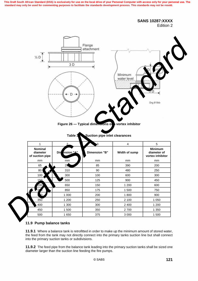
SANS 10287:XXXX Edition 2
121
Figure 26 — Typical dimensions of a vortex inhibitor
Table 39 — Suction pipe inlet clearances
1 2 3 4 5
Nominal diameter
of suction pipe Dimension "A" Dimension "B" Width of sump
Minimum diameter of
vortex inhibitor
mm mm mm mm mm
65 250 85 390 200
80 310 90 480 250
100 300 100 600 300
150 500 125 900 450
200 650 150 1 200 600
250 850 175 1 500 750
300 1 000 200 1 800 900
350 1 200 250 2 100 1 050
400 1 300 300 2 400 1 200
450 1 500 350 2 700 1 350
500 1 650 375 3 000 1 500
11.9 Pump balance tanks
11.9.1 Where a balance tank is retrofitted in order to make up the minimum amount of stored water, the feed from the tank may not directly connect into the primary tanks suction line but shall connect into the primary suction tanks or subdivisions.
11.9.2 The feed pipe from the balance tank leading into the primary suction tanks shall be sized one diameter larger than the suction line feeding the fire pumps.
© SABS
This Draft South African Standard (DSS) is exclusively for use on the local drive of your Personal Computer with access only for your personal use. The
standard may only be used for commenting purposes to facilitate the standards development process. This standards may not be resold.
Draft S
A Stan
dard
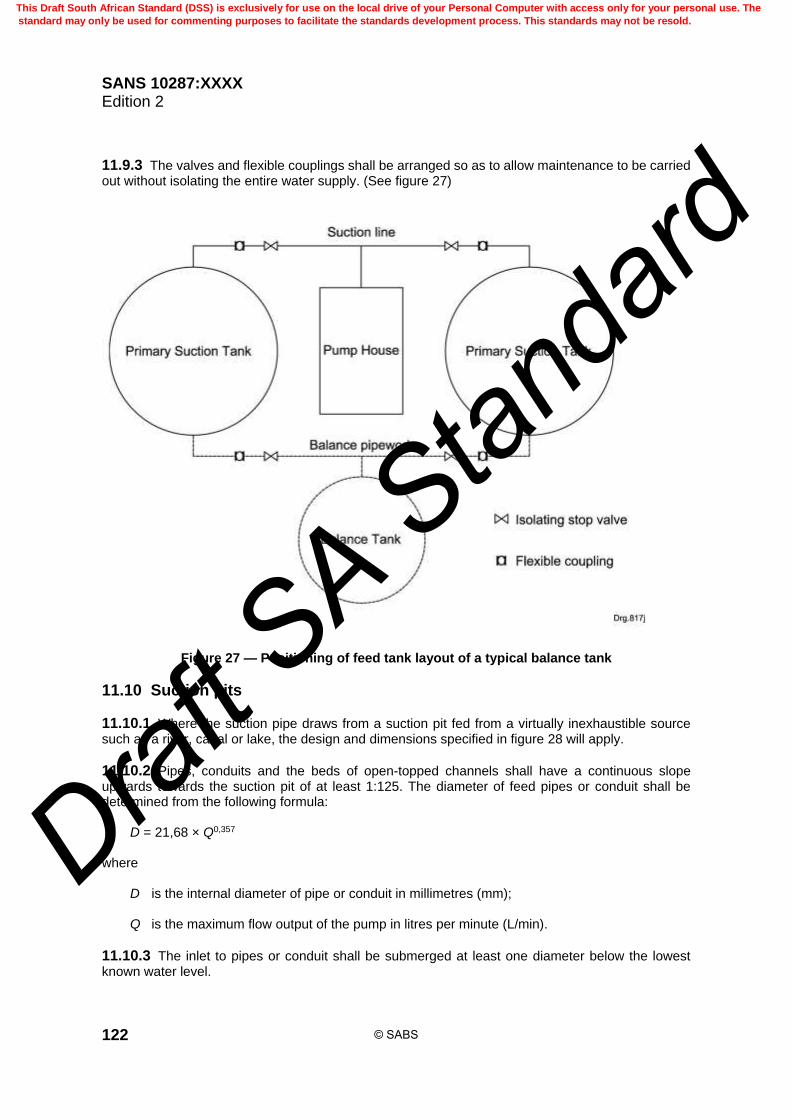
SANS 10287:XXXX Edition 2
122
11.9.3 The valves and flexible couplings shall be arranged so as to allow maintenance to be carried out without isolating the entire water supply. (See figure 27)
Figure 27 — Positioning of feed tank layout of a typical balance tank
11.10 Suction pits
11.10.1 Where the suction pipe draws from a suction pit fed from a virtually inexhaustible source such as a river, canal or lake, the design and dimensions specified in figure 28 will apply.
11.10.2 Pipes, conduits and the beds of open-topped channels shall have a continuous slope upwards towards the suction pit of at least 1:125. The diameter of feed pipes or conduit shall be determined from the following formula: D = 21,68 × Q0,357 where D is the internal diameter of pipe or conduit in millimetres (mm); Q is the maximum flow output of the pump in litres per minute (L/min).
11.10.3 The inlet to pipes or conduit shall be submerged at least one diameter below the lowest known water level.
© SABS
This Draft South African Standard (DSS) is exclusively for use on the local drive of your Personal Computer with access only for your personal use. The
standard may only be used for commenting purposes to facilitate the standards development process. This standards may not be resold.
Draft S
A Stan
dard
SANS 10287:XXXX Edition 2
123
11.10.4 The depth "d" of water in open channels or weirs, including the weir between the settling chamber and suction chamber below the lowest known water level of the water source shall be not less than that shown in table 40 for the corresponding width "w" and flow, where the flow is the maximum flow output of the pump, i.e., the pump duty point.
11.10.5 The total depth of open channels and weirs should accommodate the highest known water level of the water source.
11.10.6 Each suction inlet shall be provided with a separate suction and settling chamber.
11.10.7 Provision shall be made for each suction and settling chamber to be isolated for cleaning, maintenance or repair.
11.10.8 The dimension of the suction chamber and the location of suction pipes from the walls of the chamber their submergence below the lowest known water level and clearance from the bottom shall comply with 11.8 and figure 28.
11.10.9 The settling chamber shall have the same width and depth as the suction chamber and a length of at least 4,4√h, where "h" is the depth of the settling chamber.
11.10.10 Before entering the settling chamber, the water shall first pass through a removable screen of wire mesh or perforated metal plate having an aggregate clear area below the water level of 150 mm2 for each litre per minute of the determined maximum duty of the pump flow. The screen shall have a mesh of not greater than 12,5 mm2 openings and be strong enough to withstand the weight of water if it becomes obstructed.
11.10.11 Two screens shall be provided secured to a metal frame sliding vertically, one in use with the other in a raised position ready for interchange when cleaning is necessary.
11.10.12 Provision shall be made for the suction pit to be isolated for periodical cleaning and maintenance.
11.10.13 The screens and slides shall be constructed of corrosion resistant metallic material such as brass, copper, stainless steel or equivalent.
11.10.14 The inlet to the pipe or conduit feeding the suction pit shall be provided with a strainer having an aggregate clear opening of at least five times the cross-sectional area of the pipe or conduit.
11.10.15 The individual openings shall be of such a size as to restrict the passage of a 25 mm diameter sphere.
11.10.16 Where the suction inlet draws from a walled off area of the bed of the river, canal or lake, the wall itself shall be extended above the water surface with an aperture screening arrangement as described in 11.9. Alternatively, the space between the top of the wall and the water surface shall be enclosed with a screen having sufficient clear area as specified in 11.9.10.
11.10.17 The screen shall be capable of being raised for cleaning.
11.10.18 A scour valve shall be fitted in the settling chamber.
11.10.19 Excavation of the bed of the river, canal or lake to create the necessary depth for a pump suction inlet is not acceptable but, if unavoidable, the area shall be enclosed with the largest practicable screen, but in any case having sufficient clear area as specified in 11.9.10.
© SABS
This Draft South African Standard (DSS) is exclusively for use on the local drive of your Personal Computer with access only for your personal use. The
standard may only be used for commenting purposes to facilitate the standards development process. This standards may not be resold.
Draft S
A Stan
dard

SANS 10287:XXXX Edition 2
124
Table 40 — Minimum depth of water and width of open channels and weirs for corresponding inflows
1 2 3 4 5 6
Depth d mm = 250 Depth d mm = 500 Depth d mm = 1 000
Width Q max Width Q max Width Q max
mm L mm L mm L
88 280 82 522 78 993
125 497 112 891 106 1 687
167 807 143 1 383 134 2 593
215 1 197 176 1 960 163 3 631
307 2 064 235 3 159 210 5 647
334 2 342 250 3 506 223 6 255
410 3 157 291 4 482 254 7 825
500 4 185 334 5 592 286 9 577
564 4 953 361 6 340 306 10 749
750 7 261 429 8 307 353 13 670
1 113 12 054 527 11 415 417 18 066
1 167 12 792 539 11 816 425 18 635
1 500 17 379 600 13 903 462 21 411
2 000 24 395 667 16 271 500 24 395
4 500 60 302 819 21 949 581 31 142
– – 1 000 29 173 667 38 916
– – – – 2 000 203 320
© SABS
This Draft South African Standard (DSS) is exclusively for use on the local drive of your Personal Computer with access only for your personal use. The
standard may only be used for commenting purposes to facilitate the standards development process. This standards may not be resold.
Draft S
A Stan
dard

SANS 10287:XXXX Edition 2
125
Figure 28 — Suction tanks and suction pits
© SABS
This Draft South African Standard (DSS) is exclusively for use on the local drive of your Personal Computer with access only for your personal use. The
standard may only be used for commenting purposes to facilitate the standards development process. This standards may not be resold.
Draft S
A Stan
dard

SANS 10287:XXXX Edition 2
126
12 Automatic pump
12.1 General
12.1.1 The competent sprinkler installer shall be responsible for the supply and installation of automatic pumping sets which shall comply with this standard.
12.1.2 A pump shall have a stable head over flow curve, i.e. one in which the maximum head and shut off head are coincidental, and the total head declines continuously with an increasing rate of flow.
12.1.3 Pump sets shall be capable of satisfying the flow rate and pressure requirements of any assumed maximum areas of operation in the system under consideration when the pump suction tank level is at the low water line.
12.1.4 The pump shall provide a pressure of at least 50 kPa higher than that required for the most unfavourable assumed maximum area of operation (Pmax).
12.1.5 The pump shall have a stable head over flow curve, i.e. one in which the maximum head and shut off head are coincidental, and the total head declines continuously with an increasing rate of flow.
12.1.6 The maximum predicted flow shall be assumed to occur at the intercept of the system demand flow/pressure relationship for the hydraulically most favourable assumed maximum area of operation with the pump performance flow/pressure characteristic, when the pump suction tank water level is at the low water line.
12.1.7 Under no circumstance may any fire pump be stopped other than that which is allowed in this standard.
12.1.8 A fire pump shall start automatically and shall be stopped manually.
12.1.9 The fire pump, driver, controller, water and power supply shall be protected against possible interruption of service through damage caused by weathering of any description, explosion, fire, rodents, insects, vandalism, or any other adverse condition.
12.1.10 Where more than one pump is installed, each pump shall have compatible characteristic curves and be capable of operating in parallel at all possible flow rates.
12.1.11 All main isolating and test valves within and outside the pump house shall be secured in their correct operative positions with 25 mm link chain and padlocks and subsidiary valves with light chain and keyed alike padlocks.
12.1.12 Pumping in series is not an acceptable configuration for sprinkler systems. Fire pumps shall be provided with a float-operated air release valve having a nominal minimum diameter of not less than 12,5 mm discharging to atmosphere.
12.2 Pump room
12.2.1 Direct access to a pump house or pump room shall be from the outside and not through the protected buildings.
12.2.2 The pump room, pump house or compartment shall have a fire resistance of no less than 60 min.
© SABS
This Draft South African Standard (DSS) is exclusively for use on the local drive of your Personal Computer with access only for your personal use. The
standard may only be used for commenting purposes to facilitate the standards development process. This standards may not be resold.
Draft S
A Stan
dard

SANS 10287:XXXX Edition 2
127
12.2.3 If the pump room is located within a building, access shall be through a 120 min fire rated passage, stairs or combination of these.
12.2.4 If the pump room is a compartment within the sprinkler protected premises or is a building adjacent to the protected premises, it shall be constructed from brick, stone or concrete creating the greatest separation possible.
12.2.5 Where the pump room is a separate building it shall be constructed of brick, stone or concrete.
12.2.6 Where the pump room is located within the protected premises, it shall be located within a 120 min fire rated compartment.
12.2.7 Unless all reasonable precautions are taken in order to meet the requirements in this standard, steel shipping containers are not suitable as pump houses for the South African environment.
12.2.8 The temperature of the pump room shall be maintained above 10 °C where compression ignition type engines are used.
12.2.9 Where it is impractical to heat the pump house to the required temperature, all equipment within the pump house shall be heated to 10 °C.
12.2.10 Adequate natural ventilation shall be provided and increased if necessary to limit the temperature rise in the pump room to not more than 10°C above the ambient temperature under stationary to engine full load conditions for a period of not less than 6 h.
12.2.11 All gauges, isolation devices, test valves, control valves shall be located no more than 1,7 m above floor, walkway or platform level and shall be easily accessible and visible and free of clutter.
12.2.12 Where appropriate, platforms, steps or elevated walkways shall be provided to negate trip hazards and obstacles. Positioning of equipment close to exhaust pipes or manifolds shall be avoided.
12.2.13 The pump room shall be locked at all times and a notice stating where the keys are obtainable shall be mounted on the door.
12.2.14 Where a pump room is situated remote from the sprinkler protected premises, such that it is impracticable to provide sprinkler protection from one or other of the installation control valve sets in the premises, the sprinkler protection in such a pump house may be supplied from the nearest accessible point on the downstream side of the non-return valve on the supply pipe from the pump.
12.2.15 In such cases there shall be a controlling stop valve, secured in the open position, fitted on the supply pipe to the sprinklers together with an alarm device which is approved with visible and audible indications of the operation of the sprinklers provided at the pump house.
12.2.16 The alarm shall be in an acceptable position at a manned location in the plant or on the premises.
12.2.17 A 15 mm drain valve shall be provided downstream of the flow alarm to permit a practical test of the alarm system.
12.2.18 Sprinklers for the protection of a pump room shall have a minimum operating temperature of 93 °C.
12.2.19 No sprinkler shall be located within 800 mm of the diesel engine exhaust pipe.
© SABS
This Draft South African Standard (DSS) is exclusively for use on the local drive of your Personal Computer with access only for your personal use. The
standard may only be used for commenting purposes to facilitate the standards development process. This standards may not be resold.
Draft S
A Stan
dard

SANS 10287:XXXX Edition 2
128
12.2.20 Sufficient natural lighting (where the pump house is located above ground) is recommended and artificial and emergency lighting shall be provided in the pump house. Lighting levels throughout the pump room shall be at least 500 lux.
12.2.21 Where possible lighting switches shall be positioned adjacent to the entry to the pump house or room.
12.2.22 Access doors are not acceptable for providing natural lighting.
12.2.23 Where compression ignition type engines are used, the pump house shall have adequate natural and mechanical ventilation for engine aspiration.
12.2.24 Mechanical extraction shall be positioned at high level close to the roof or ceiling of the pump house whereas louvers shall, where possible, be positioned at a lower level in order to draw air across the diesel engine.
12.2.25 Louvers or air bricks alone are not deemed to provide adequate ventilation. It shall be ensured that the minimum extraction rates are in accordance with table 41.
Table 41 — Mechanical ventilation air extraction
1 2
Size of engine Minimum air extraction
2 and 3 cylinder naturally aspirated 6,0 m3 per min
4 cylinder naturally aspirated 6,0 m3 per min
4 cylinder turbo charged 6,0 m3 per min
6 cylinder naturally aspirated 6,0 m3 per min
6 cylinder turbo charged 12,0 m3 per min
8 cylinder engines 15,0 m3 per min
Above 7 L capacity 20,0 m3 per min
12.2.26 Provisions shall be made for the pump house floor to be sloped to provide natural drainage of the pump room where the pump room is above finished ground level.
12.2.27 An adequately sized sump pump shall be provided and a high water level warning device fitted to this for pump rooms which are partially below the finished ground level.
12.2.28 The cooling water from the engine jacket and the leak off water from the pumps shall be taken back to the suction tank or to a suitable drainage point.
12.2.29 The pump house shall be arranged and sized so as to allow easy unobstructed access to pipework, pump units and controlling equipment.
12.2.30 A clearance of not less than 5 mm shall be allowed around all pipes that pass through walls or floors of the pump room to provide relief against any possible movement. The space around the pipe shall be watertight and packed with mineral fibre, asphalt mastic or other suitable material held in place with collars on each side.
12.2.31 All pressure gauges within the pump house shall comply to the requirements of 21.3.
© SABS
This Draft South African Standard (DSS) is exclusively for use on the local drive of your Personal Computer with access only for your personal use. The
standard may only be used for commenting purposes to facilitate the standards development process. This standards may not be resold.
Draft S
A Stan
dard

SANS 10287:XXXX Edition 2
129
12.2.32 There shall be a suitable number of joints on the pipework to allow any of the equipment to be removed for overhauling or replacement to minimize the amount of time the fire pump is inoperative for maintenance or other reasons.
12.2.33 All pipework shall be suitably supported with at least one support on both suction and delivery as close to the pump casing as possible and no strain shall be imposed on the pump casing by the pipework.
12.2.34 It shall be possible to unbolt suction and delivery flange bolts on the pump and no visible movement shall be observed in the pipework at this time.
12.2.35 The pump and driver shall be mounted on a common base plate and connected by the means of a flexible coupling.
12.2.36 A suitable coupling guard shall be fitted over the flexile coupling.
12.2.37 Provision shall be made for suitable lifting lugs permanently attached to the base plate for safe rigging of the unit.
12.2.38 All equipment within the pump room shall be clearly labelled and tagged. This in turn shall relate to comprehensive operating instructions detailing the required testing and maintenance routine.
12.2.39 All test and drainage lines within the pump house shall be taken separately to a suitable drainage point or facility external to the pump house whereby the discharging water will not wet the person testing the system.
12.2.40 The base plate shall be securely attached to a concrete foundation in accordance with the manufacturer’s specifications.
12.2.41 The pump and driver mounted on the common base plate shall be fixed by way of foundation bolts to a reinforced concrete foundation plinth which shall either be a) cast as an integral part of the pump room floor, or b) cast as a separate foundation, set into the pump room floor.
12.2.42 The foundation shall be installed independent and free of expansion joints and shall be at least 300 mm wider than the pump set on all sides.
12.2.43 The minimum height that the foundation shall project above the floor shall not be less than 150 mm but shall have sufficient height to achieve the necessary weight, to accommodate the pockets for fixing bolts and to ensure that the foundation bolts do not come into contact with water. Where a floating plinth is used it shall be between 3 and 5 times the weight of the unit in order to ensure alignment is maintained and vibration is taken up.
12.2.44 The foundation should preferably be made of reinforced concrete that has been poured without interruption to within 25 mm of the finished height.
12.2.45 The top surface shall be well scoured and grooved before the concrete sets in order to provide a bonding surface for the grout.
© SABS
This Draft South African Standard (DSS) is exclusively for use on the local drive of your Personal Computer with access only for your personal use. The
standard may only be used for commenting purposes to facilitate the standards development process. This standards may not be resold.
Draft S
A Stan
dard
SANS 10287:XXXX Edition 2
130
12.2.46 The foundation height may be calculated as follows:
H = 2 400
W
B L
where H is the height of the base in metres (m); W is the total weight of the pump set in kilograms (kg); 2400 is the density of normal concrete in kilograms per cubic metres (kg/m3); B is the foundation width in metres (m); L is the foundation length in metres (m).
12.2.47 Machinery foundations, frames or platforms are acceptable providing these mountings are of sufficient strength and mass to withstand the static and dynamic forces imposed by the pump set.
12.2.48 The base plate with pump and driver mounted on it shall be set level on the foundation. The coupling halves shall be disconnected and the pump and driver checked for alignment. They shall be checked for alignment again after all pipework has been connected, the base plate levelled, and the base plate and foundation bolts grouted in concrete.
12.2.49 Only after alignment are the coupling halves to be reconnected.
12.2.50 After commissioning the pump base plate shall be completely filled with grout of high strength and poured in accordance with the manufacturer’s instructions. This will compensate for uneven foundations as well as evenly distribute the weight of the pump set, prevent movement and reduce vibration.
12.2.51 When the grout has thoroughly dried, an oil based paint which is approved shall be applied to the exposed faces of the grout in order to prevent air and moisture coming into contact with it.
12.3 Pump set installation and fixing
12.3.1 The pump set shall be installed before installing the suction and delivery lines. This will ensure that the pipes are positioned to match the pump location and prevent a transmission of load which will induce strain onto the pump casing.
12.3.2 The following procedures shall be carried out before and during the pump installation: a) check the position and dimensions of the foundation for correctness before the pump set is put in
place; b) position the pump set level on the foundation using shims or packing pieces at the point specified
by the pump set manufacturer; c) support the pump set frame on at least two sides of any anchor bolt using shims or packing pieces.
After levelling the pumps at the nuts, the anchor bolts may be partially tightened, systematically and evenly, but not to the final torque setting;
d) ensure that foundation bolts pass through purpose made holes in the pump set base frame and
not through lugs welded to the side of the base plate frame;
© SABS
This Draft South African Standard (DSS) is exclusively for use on the local drive of your Personal Computer with access only for your personal use. The
standard may only be used for commenting purposes to facilitate the standards development process. This standards may not be resold.
Draft S
A Stan
dard

SANS 10287:XXXX Edition 2
131
e) where specified by the pump set manufacturer, grout pump sets to the foundation by filling the
pump base with grout as required by this standard; f) grout the shims or packing pieces in place with grout extending along the full length of the frame; g) after the grout is fully cured, tighten the nuts on the anchor bolts to the torque setting recommended
by the pump set manufacturer; and
h) check the pump set alignment after the pipework has been connected to the pump.
12.3.4 The pump set shall not be re-shimmed or moved to accommodate misalignments of the system pipework.
12.3.5 The pump set anchor bolt nut threads shall be fully engaged with the bolt which shall extend beyond the nut by at least two threads.
12.3.6 The weight of pump suction pipework, delivery pipework and valves, and any dynamic forces acting on them shall be carried by purpose made pipe supports and not by the pump branches.
12.3.7 Pump test lines shall be adequately anchored and restrained (see figures 29 and 30).
Figure 29 — Typical examples of pump set base frame fixing
© SABS
This Draft South African Standard (DSS) is exclusively for use on the local drive of your Personal Computer with access only for your personal use. The
standard may only be used for commenting purposes to facilitate the standards development process. This standards may not be resold.
Draft S
A Stan
dard

SANS 10287:XXXX Edition 2
132
Figure 30 — Typical examples of pump set base frame fixing
12.4 Suction pipework and fittings
12.4.1 Gear driven butterfly valves are acceptable for use on suction lines in accordance with this standard. These can increase turbulence and increase the possibility of blockages. It is recommended that the pump suction stop valves be of the outside screw and yoke (OS and Y) gate valve type (see figure 31).
12.4.2 Valves or flexible couplings shall not be fitted directly to the pump suction inlet. It is recommended that a distance of ten diameters be allowed between any fitting and the pump inlet on the suction line.
12.4.3 Centrifugal pumps shall be installed below the minimum effective storage level of the water supply which in the case of suction tanks is the low water level "X", (see figure 25), and in the case of natural unlimited water supplies such as rivers, canals or lakes will be the lowest known water level of the supply.
12.4.4 Means shall be provided for the release of air which might become trapped in the upper part of the pump case. This shall be achieved automatically where a pump operates under suction lift conditions.
12.4.5 The suction pipes under positive head conditions shall be symmetrical so that the suction tanks will drain proportionately and, in the case of more than one pump set being installed, each pump will receive its proportional supply.
12.4.6 When the suction pipe and the pump suction are not of the same size, they shall be connected with an eccentric tapered reducer, (transition piece), in such a way as to avoid air pockets in the pipework, i.e. belly down. The transition piece shall have a maximum included angle not exceeding 15o and shall be at least 2 diameters long.
12.4.7 Bends in the suction pipework shall be kept to a minimum. Bends shall be of the smooth swept type having a radius of curvature of not less than one-and-a-half-times the diameter of the suction pipe.
12.4.8 Tees shall be swept tees.
© SABS
This Draft South African Standard (DSS) is exclusively for use on the local drive of your Personal Computer with access only for your personal use. The
standard may only be used for commenting purposes to facilitate the standards development process. This standards may not be resold.
Draft S
A Stan
dard
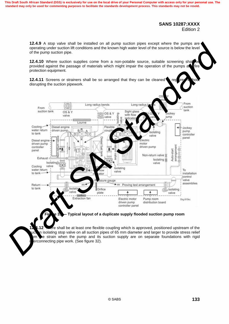
SANS 10287:XXXX Edition 2
133
12.4.9 A stop valve shall be installed on all pump suction pipes except where the pumps are operating under suction lift conditions and the known high water level of the source is below the level of the pump suction pipe.
12.4.10 Where suction supplies come from a non-potable source, suitable screening shall be provided against the passage of materials which might impair the operation of the pumps and fire protection equipment.
12.4.11 Screens or strainers shall be so arranged that they can be cleaned or repaired without disrupting the suction pipework.
Figure 31 — Typical layout of a duplicate supply flooded suction pump room
12.4.12 There shall be at least one flexible coupling which is approved, positioned upstream of the suction isolating stop valve on all suction pipes of 65 mm diameter and larger to provide stress relief from the strain when the pump and its suction supply are on separate foundations with rigid interconnecting pipe work. (See figure 32).
© SABS
This Draft South African Standard (DSS) is exclusively for use on the local drive of your Personal Computer with access only for your personal use. The
standard may only be used for commenting purposes to facilitate the standards development process. This standards may not be resold.
Draft S
A Stan
dard

SANS 10287:XXXX Edition 2
134
Figure 32 — Typical schematic layout of pump suction and delivery pipework
12.5 Pumps installed under positive head conditions
12.5.1 Where pumps are installed under positive head conditions a common suction pipe is permitted and the additional conditions given in 12.5.2 to 12.5.4 (inclusive) shall be observed.
12.5.2 The diameter of the pipe shall be such that a velocity of 1,8 m per second is not exceeded when the pump is operating at maximum flow rate, i.e. Qmax.
12.5.3 The suction line shall be laid truly horizontal or a fall towards the pump may be allowed provided so that no air can be trapped in the suction pipe for flooded suction or positive head conditions.
12.5.4 In the case of positive head conditions for open water sources such as rivers, lakes canals and water features, the strainer shall be fitted between the suction tank and pump, outside the pump house and shall have a stop valve installed on the upstream side.
12.6 Pumps installed under suction lift conditions
12.6.1 Suction lift is to be avoided where possible.
12.6.2 Figure 33 provides the general arrangement of a pump operating under suction lift conditions.
12.6.3 Where pumps are installed with their centre line above the minimum effective storage level of the water supply or installed with less than two-thirds of the effective storage capacity in the tank above the top of the pump casing, or where, in the case of natural unlimited water supplies such as
© SABS
This Draft South African Standard (DSS) is exclusively for use on the local drive of your Personal Computer with access only for your personal use. The
standard may only be used for commenting purposes to facilitate the standards development process. This standards may not be resold.
Draft S
A Stan
dard

SANS 10287:XXXX Edition 2
135
rivers, canals or lakes, the lowest known water level of the supply is below the top of the pump casing, they are considered to be under suction lift conditions.
12.6.4 The diameter of the pipe shall be such that a velocity of 1,5 m per second is not exceeded when the pump is operating at maximum flow rate up to Qmax.
12.6.5 For such installations the vertical height between the lowest level of the water supply and the centre line of the pump shall not exceed 3,2 m at sea level.
12.6.6 For every 100 m increase above sea level the vertical height shall be reduced by 100 mm. Pumps in general and those working at high altitudes should be under positive head conditions.
12.6.7 At the lowest point on the pump suction pipe a foot valve shall be provided and the position of the point of entry to the foot valve shall comply with the dimensions given in columns 2 and 3 of table 39.
12.6.8 Where a pump is installed under suction lift conditions, a strainer with openings that shall prevent the induction of a 5 mm solid sphere shall be fitted upstream of the foot valve on the pump suction line and shall have an aggregate open area of at least 1,5 times the cross-sectional area of the suction pipe. It shall be fitted in order to ensure it can be cleaned without the tank having to be emptied.
12.6.9 Where the pump is operating under suction lift conditions, there shall be adequate provision made, (lifting lugs), to ensure that the foot valve and strainer can easily be removed for an overhaul. There shall be at least one flanged joint above the level of the water and before the pump. Consideration shall be given to the provision of guides or runners to enable the assembly to be removed and repositioned without causing damage or stressing other components.
12.6.10 Automatic priming equipment shall be provided to ensure that the pump will be fully primed with water at all times, and shall take the form of an elevated cistern maintained automatically filled from an alternative supply, with a priming pipe therefrom taken direct to the pump delivery branch upstream of the non-return valve on the connection in close proximity to the pump.
12.6.11 Where pumps are under suction lift or negative head conditions, there shall be independent suction pipes and elevated priming arrangements for each unit which shall not be interconnected.
12.6.12 The suction pipework shall be laid truly horizontal or with a continuous rise towards the pump to avoid the possibility of air locks for suction lift conditions and shall not exceed 30,0 m in length inclusive of fittings. Mechanical seals shall be used on pumps installed under suction lift conditions.
12.6.13 Means shall be provided whereby the cistern, the pump case and the suction pipework are maintained filled with water notwithstanding serious leakage from the foot valve, the arrangements being such that the pump is started if the water in the cistern drains from it at a greater rate than can be supplied from the normal source and the water level drops to two thirds of the normal level.
12.6.14 The water for priming the pump suction connection shall be provided by a connection from a branch from a town main forming a supply to the premises. Such connection shall be made on the town main side of the non-return valve, upstream of any pressure tapping for the pump starting device.
12.6.15 The size of the priming tank shall not be less than four times the capacity of the suction pipe from the pump to the foot valve or 500 L capacity whichever is the greater.
12.6.16 The size of the priming pipe shall not be less than 50 mm nominal diameter.
© SABS
This Draft South African Standard (DSS) is exclusively for use on the local drive of your Personal Computer with access only for your personal use. The
standard may only be used for commenting purposes to facilitate the standards development process. This standards may not be resold.
Draft S
A Stan
dard

SANS 10287:XXXX Edition 2
136
Figure 33 — General arrangements for a pump under suction lift conditions
12.7 Delivery pipework and fittings
12.7.1 A town main bypass connection shall be provided unless duplicate supplies are provided whereby the bypass is recommended but not required. The connection is to be taken to the delivery side of the pump downstream of the non-return and stop valve. The bypass shall be the same diameter as the water supply connection and shall be fitted with a non-return valve. Stop valves, chained in the closed position, shall be fitted on the upstream and the downstream side of the non-return valve.
12.7.2 When the delivery pipework and the pump delivery are not of the same size, they shall be connected with a concentric reducer, i.e. a nozzle shaped transition piece. It shall be ensured that all downstream pipework is suitably rated in terms of the static and working pressure of the system.
12.7.3 A non-return valve shall be installed on all pump delivery assemblies.
12.7.4 A stop valve shall be installed on the downstream side of the non-return valve to make the non-return valve and pump accessible for repair.
12.7.5 A pressure gauge shall be connected to the delivery pipework between the non-return valve and the pump delivery via a 10 mm isolating gauge cock or on the pump casing if an outlet has been provided by the pump manufacturer. The face of the dial shall read in kilopascals and have a pressure range of at least 1,5 times the rated working pressure of the pump and not less than 10 % above the pump churn pressure.
12.7.6 There shall be a test valve and pipe connection coupled to the pump delivery branch downstream of the non-return valve, including an orifice plate, if necessary, to facilitate a running pressure test on the pump at any flow up to Qmax.
© SABS
This Draft South African Standard (DSS) is exclusively for use on the local drive of your Personal Computer with access only for your personal use. The
standard may only be used for commenting purposes to facilitate the standards development process. This standards may not be resold.
Draft S
A Stan
dard

SANS 10287:XXXX Edition 2
137
12.7.7 Alternatively, a direct reading flow meter which is approved may be used to test the pump. Where the pump draws its water from a sump, care shall be taken to avoid aeration of the water during testing.
12.7.8 The test water shall be returned to the suction tank.
12.7.9 Where it is impracticable to dispose of the water discharged under a full load test condition, details of the facilities available shall be acceptable to all parties.
12.7.10 Where more than one pump forms the source of supply to the fire protection system and they all have identical characteristics, the test pipe may be taken from the common delivery pipe, provided a stop valve is fitted in the delivery pipe downstream of the test connection.
12.7.11 The test pipe shall have a direct reading flow meter or other device attached which is approved.
12.7.12 While not testing, the stop valves on the test pipe shall be secured in the closed position by a chain and padlock.
12.7.13 All pump delivery stop valves shall be of the gear driven butterfly type and secured in the open position by 25 mm link chains and padlocks.
12.7.14 A direct connection, without isolating facilities, for the starting mechanism shall be taken from downstream of the delivery stop valve and shall be not less than 20 mm diameter.
12.7.15 Each pump shall have separate starting arrangements.
12.7.16 All pump delivery pipework, inclusive of the installation pipework, shall be pressure tested to at least one and a half times the maximum envisaged pressure that will be exerted on the system at the highest sprinkler for a period of not less than 2 h.
12.7.17 Sprinkler pipework shall be pressure tested to the above minimum pressure regardless of the type and class of water supply installed.
12.8 Jockey or make-up pump
12.8.1 Where automatic pumps are installed and in order to cater for natural leakage a jockey or make-up pump shall be fitted to maintain pressure in the system.
12.8.2 The jockey pump shall be free of hunting and shall not cause water hammer.
12.8.3 The jockey or make-up pump shall have a rated capacity of not less than any normal leakage rate.
12.8.4 The jockey or make-up pump shall be of centrifugal pump design having a discharge pressure sufficient to maintain the desired fire protection system pressure.
12.8.5 They shall have steep head to capacity characteristics to avoid excessive flow when pumping within the pressure operating range.
12.8.6 The jockey pump shall be sized so as to prevent this pump from maintaining one sprinkler in operation without the main fire pump starting.
© SABS
This Draft South African Standard (DSS) is exclusively for use on the local drive of your Personal Computer with access only for your personal use. The
standard may only be used for commenting purposes to facilitate the standards development process. This standards may not be resold.
Draft S
A Stan
dard

SANS 10287:XXXX Edition 2
138
12.8.7 The jockey or make-up pump pressure operating range shall not exceed 1200 kPa at any sprinkler and shall not be less than the pressure switch setting to start the fire pump.
12.8.8 The jockey or make-up pump shall be set to start automatically when the pressure in the system has fallen to a value of not less than 90 % of the churn pressure of the primary pump and to shut off automatically when the system pressure has reached either the churn pressure of the primary pump or 1200 kPa, whichever is the lesser.
12.8.9 A fire pump shall not be used as a pressure maintenance pump.
12.8.10 The kilowatt rating of the jockey pump motor shall be sufficient to drive the jockey pump from no flow to maximum flow condition without overloading.
12.8.11 A jockey or make-up pump shall be of cast iron casing construction with bronze internal parts and high tensile steel shaft or better.
12.8.12 The suction pipe for the jockey or make-up pump shall be taken from the side or top of the main fire pumps suction line and not from the bottom where sediment may be drawn into the unit.
12.8.13 A non-return valve shall be installed in the jockey or make-up pump discharge pipe.
12.8.14 Stop valves and unions shall be installed in such places as needed to make the jockey or make-up pump and non-return valve along with other miscellaneous fittings accessible for repair or removal and replacement.
12.8.15 Means shall be provided to reduce the applied water pressure to the jockey or make-up pump starting device to simulate the conditions of automatic starting and stopping at the requisite pressures.
12.8.16 Full details of the proposed jockey pump shall be submitted to a testing authority simultaneously with the details required for pump performance testing.
12.9 General requirements for pumps
12.9.1 Pumps of differing flow and pressure characteristics shall not be used for making up the total calculated demand of a sprinkler system.
12.9.2 The performance characteristics of pumps shall be such that the pressure falls progressively with the rate of demand, so that whilst being capable of providing the rate of flow and pressure required at the highest and most unfavourable parts of the protected premises, the output will be so controlled that there is not an excessive rate of discharge at the lowest level in areas close to the installation valves.
12.9.3 The pump performance test results shall show that the pressure and flow characteristics of the pump will adequately satisfy the calculated requirements of the most unfavourable and most favourable areas of operation.
12.9.4 It is recommended that the net positive suction head (NPSH), required for any pump when discharging at the maximum flow rate should not exceed 5,9 m.
12.9.5 If the NPSH required by the pump exceeds 5,9 m then the net positive suction head required (NPSHR), required by the pump under installed conditions will be the net positive suction head available (NPSHA) less 1,5 m to a minimum of the maximum available flow capacity of the required flow rate.
© SABS
This Draft South African Standard (DSS) is exclusively for use on the local drive of your Personal Computer with access only for your personal use. The
standard may only be used for commenting purposes to facilitate the standards development process. This standards may not be resold.
Draft S
A Stan
dard
SANS 10287:XXXX Edition 2
139
12.9.6 The available NPSHA shall be calculated at the pumps duty point as follows: NPSHA = Ps + (Pa – 1,5) – Pv − Pf where NPSHA is the net positive suction head available in metres (m);
Ps is the suction head measured from the lowest water level to the pump suction centre line or impeller eye in metres (m);
Pa is the effective absolute atmospheric pressure at the installed altitude in metres (m); Pv is the vapour pressure in metres (m), (assumed to be 0,32 m); Pf is the friction loss in suction pipework in metres (m), using the pump duty point.
12.9.7 The closed outlet valve pressure, under installed conditions shall not exceed 1 200 kPa.
12.9.8 In selecting pump characteristic curves, allowance shall be made for the increase in pressure at zero flow due to an increase in shaft speed of the prime mover and for an increase or decrease in pressure due to a positive or negative pressure at the pump suction flange.
12.9.9 Means for venting all cavities of the pump casing shall be provided unless the pump is made self-venting by arrangement of its branches. If a pump is installed under suction lift conditions, Ps may be negative, however the minimum NPSH available shall not be less than 6,4 m.
12.9.10 Pumps shall be of centrifugal horizontal split case or end suction horizontal shaft design.
12.9.11 Pumps supplying life safety installations and ESFR sprinkler installations shall have positive suction head conditions.
12.9.12 Where the pump parts mentioned in 12.9.14 and 12.9.15 are used, the materials shown in table 42 shall apply.
12.9.13 For end suction pumps bronze case wear rings shall be fitted to the pump casing.
12.9.14 Cast iron shall not be used for any wetted rotating component or stationary part in close running contact with the rotating member. Pumps constructed other than as in 12.9.1 to 12.9.13 shall have the design features which are approved for sprinkler use.
12.9.15 All pump parts shall be standard stock items with no special treatment, i.e. impeller under filing, polishing or other changes are not permissible.
12.9.16 For end suction pumps it shall be ensured that the bearing housing is adequately supported.
© SABS
This Draft South African Standard (DSS) is exclusively for use on the local drive of your Personal Computer with access only for your personal use. The
standard may only be used for commenting purposes to facilitate the standards development process. This standards may not be resold.
Draft S
A Stan
dard

SANS 10287:XXXX Edition 2
140
Table 42 — Pump part materials
1 2
Part Material
Bearings Ball/roller type Stainless steel
Casing Cast Iron
Case wear rings Bronze
Gland Bronze
Gland packing High grade graphite cotton
Impeller Bronze
Lantern rings Bronze or stainless steel
Mechanical seals Carbon ceramic - Suction lift
Shaft E N 8 Steel
Shaft sleeves Bronze
Stuffing box bushes Bronze
12.9.17 The coupling between the engine or motor and the pump shall allow each unit to be removed without disturbing the other.
12.9.18 The pump shall be fully operational at the designed duty point within 15 s after starting.
12.9.19 Pumps shall have a direct drive and shall start automatically.
12.9.20 The automatic starting device for pumps shall be of a pattern which is approved and set to operate the primary pump when the pressure in the trunk main has fallen to a value not less than 80 % of the pressure in the trunk main when the pump is churning or 100 kPa below the duty pressure of Pmax if this is above or equal to 80 % of the churn pressure.
12.9.21 The second pump of a duplicate pump system shall be set to start when the trunk main falls to a value of 100 kPa below the cut in pressure of the primary pump but not less than 60 % of the churn pressure of the primary unit. The second pump of a three half capacity pump system shall be hardwired to start automatically within 30 s of the primary pump coming into operation.
12.9.22 Means shall be provided for manual starting by reproducing the pressure reduction. Once started, the pump shall run continuously until stopped manually.
12.9.23 A fall in water pressure in the sprinkler system, which is intended to initiate the automatic starting of a pump or pumps, shall at the same time provide a visual and audible alarm preferably in an area with responsible manning where the pump house is situated remotely from the risk.
12.9.24 The starting of the pump or pumps shall not cause the cancellation of the alarm.
12.9.25 The visual and audible alarm shall form part of an alarm system which is approved for sprinkler use and shall be initiated by electrically separate contacts. These contacts shall consist of one change-over moving contact and two fixed contacts, one normally open and one normally closed, or two completely separate contacts, one normally open and one normally closed. The contacts shall be wired to clearly identified terminals on the terminal strip of the controller. The contacts shall be of the positive make or break type, but the alarm system shall be designed to operate on "fleeting" signals and shall latch on to either momentary make or break signals.
© SABS
This Draft South African Standard (DSS) is exclusively for use on the local drive of your Personal Computer with access only for your personal use. The
standard may only be used for commenting purposes to facilitate the standards development process. This standards may not be resold.
Draft S
A Stan
dard

SANS 10287:XXXX Edition 2
141
12.9.26 In all cases, each pump shall be provided with a plate stating the following: a) the endurance test approval number; b) the name of the company that supplied the unit; c) the pump model; d) the pump serial number; d) the impeller diameter; e) the rotational speed; f) the churn pressure of the pump; g) the duty point flow and pressure;. h) the maximum power absorbed at the flow rate given; i) the flow and pressure of Pmax; and j) the flow and pressure of Qmax.
12.9.27 Where the performance characteristic is achieved with an orifice plate not integral with the pump delivery, the plate shall carry a reference to the fact that the performance given is that of the pump and orifice plate combination, together with the flow of the pump, pressure loss across the orifice plate and the K-factor of the orifice plate.
12.9.28 Sufficient water shall be permitted to circulate when the pump is running to prevent it from overheating when operating against a closed discharge valve.
12.9.29 The quantity of water discharged in litres per minute may not be less than the equivalent of 10 % of the numerical kilowatt rating of the prime mover and shall be taken into account when sizing a pump.
12.9.30 No water shall circulate when the pump set is shut down. Any incident shall be managed in accordance with the manufacturer's recommendations.
12.9.31 A flow indicator or sight glass shall be provided upstream of an isolating valve that has a 10 mm hole drilled into the gate in order to ensure water passes through this valve when the pump is operational and the valve is closed.
12.9.32 Means shall be provided to reduce the applied water pressure to the starting device to simulate the condition of automatic starting at the requisite pressure.
12.9.33 The means described in 12.9.32 can take the form of a drain valve on the hydraulic connection to the pump starting pressure switch and suitable permanent drainage facilities shall be provided.
12.9.34 Where valves are used to control the drop in pressure as described in 12.9.32 and 12.9.33 they shall be of the diaphragm type.
12.9.35 In order that the pressure may be dropped at a suitable rate to judge the pump cut in pressure, the drain valve referred to in 12.9.33 may be fitted with an orifice plug.
© SABS
This Draft South African Standard (DSS) is exclusively for use on the local drive of your Personal Computer with access only for your personal use. The
standard may only be used for commenting purposes to facilitate the standards development process. This standards may not be resold.
Draft S
A Stan
dard

SANS 10287:XXXX Edition 2
142
12.9.36 To facilitate testing and servicing, an isolating valve, with a bypass, shall be fitted on the hydraulic connection. The bypass shall incorporate a 3 mm orifice and a non-return valve allowing flow towards the trunk main.
12.9.37 A pressure gauge to indicate the pressure at which the pump starts shall be placed between the isolating and drain valves in such a position that it can be read during the starting test. Figure 34 is a typical example of a pump automatic starting arrangement.
12.9.38 Two pressure switches shall be provided to start the diesel engine driven pump. The second pressure switch shall be set to operate at not less than 20 kPa and not more than 50 kPa beneath the starting pressure of the primary switch. They shall be connected in parallel such that closing the contacts of either switch will start the pump with normally open contacts (see figure 34). All pressure switches shall be fitted with a 150 mm sludge and sediment trap of non-corroding material.
12.9.39 Power sufficient to drive the pump at the required pressure shall be available at all times.
12.9.40 All pressure switches, if screwed directly into a tee shall be fitted with a 150 mm sludge and sediment trap of non-corroding material. If the pressure switch is fitted onto a rising sprig of 100 mm in length, a sludge trap is not required.
12.9.41 Power for the warning systems shall be taken from a separately switched sub-circuit to that feeding the pump in the case of an electric pump. In the case of diesel engine driven pumps, the power for the warning system may not be taken from the battery which is used for automatic starting.
12.9.42 The warning system shall be equipped with its own batteries which shall have an ampere-hour capacity to provide 48 h of monitoring the complete system and 1 h of audible and visual alarm. NOTE The term "sub-circuit" means a circuit connected to a switch supplied directly from the low or medium voltage bus-bars on the fire pump room distribution board.
12.9.43 Pumps shall be driven by a diesel engine which is approved if this is the primary supply or electric motor as a primary supply and diesel engine as the secondary supply.
© SABS
This Draft South African Standard (DSS) is exclusively for use on the local drive of your Personal Computer with access only for your personal use. The
standard may only be used for commenting purposes to facilitate the standards development process. This standards may not be resold.
Draft S
A Stan
dard

SANS 10287:XXXX Edition 2
143
Figure 34 — Typical auto-start arrangement
© SABS
This Draft South African Standard (DSS) is exclusively for use on the local drive of your Personal Computer with access only for your personal use. The
standard may only be used for commenting purposes to facilitate the standards development process. This standards may not be resold.
Draft S
A Stan
dard

SANS 10287:XXXX Edition 2
144
12.10 Pump approval
12.10.1 Each complete engine and pump set shall be tested on a suitable test bed and be independently witnessed by a recognised competent person familiar with the requirements of fixed fire protection systems. Prior to testing, the information detailed in 12.11 shall be provided.
12.10.2 Adequate notifications and copies of the detailed information shall be circulated to the competent person in order that they may witness the test. Copies of a certificate showing the records of the hydrostatic and endurance test which shall be conducted as specified in 12.10.3 to 12.10.5 shall be supplied to the competent person.
12.10.3 Before shipment from the factory, each pump shall be hydrostatically tested by the manufacturer for a period of not less than 10 min.
12.10.4 The test pressure shall not be less than 1,5 times the churn pressure of the pump plus its maximum allowable suction head subject to a minimum pressure of 1 800 kPa.
12.10.5 The pump casings shall be tight at the test pressure and during the test no leakage shall occur at any joint.
12.11 Detailed endurance testing information
12.11.1 Pump 12.11.1.1 The pump test acceptance grade shall be in accordance with Class 2U of SANS 9906 in that zero negative tolerances shall be permitted other than efficiency where a negative 5 % can be accepted. The following information shall be provided: a) the pump manufacturer; b) the pump model; c) the pump serial number; d) the pump impeller diameter; e) the pump efficiency curve; f) the sprinkler installers calculated flow; g) the pressure at calculated flow; h) the net positive suction head required at all stated flows and pressures; and i) the power absorbed at calculated flow. 12.11.1.2 If a pump impeller or complete pump unit excluding the prime mover requires replacing once installed, the pump set shall be retested on site or at a suitable test bed for a period of not less than 2 hours at any flow up to the maximum. The test shall be independently witnessed by a recognised competent person familiar with the requirements of fixed fire protection systems.
12.11.2 Diesel engine The following information shall be provided: a) the make of engine;
© SABS
This Draft South African Standard (DSS) is exclusively for use on the local drive of your Personal Computer with access only for your personal use. The
standard may only be used for commenting purposes to facilitate the standards development process. This standards may not be resold.
Draft S
A Stan
dard

SANS 10287:XXXX Edition 2
145
b) the speed of engine for site conditions; and c) the rated power output.
12.11.3 Electric motor The following information shall be provided: a) the make of motor; b) the speed of motor; and c) the rated power output.
12.11.4 Endurance test — Diesel engine driven pump 12.11.4.1 The pump set shall be run at the calculated flow rates of Pmax, Qmax, pump duty and run out for 6 h. If a diesel engine requires rebuilding or replacing once installed, the pump set shall be retested on site or at a suitable test bed for a period of not less than 6 hours. 12.11.4.2 At the end of the test the engine speed, the suction and delivery pressure shall be recorded at zero, 25 %, 50 %, 75 %, 100 % (Qmax), 110 % of Qmax, duty point and 110 % of duty point. Each point shall be clearly indicated on the test curve. 12.11.4.3 The following hourly records shall be made: a) the ambient temperature; b) the lubricating oil temperature; c) the rise in temperature of the cooling water; d) the cooling water flow rate; e) the engine speed; f) if the engine is fitted with a heat exchanger, the initial temperature and the rise in temperature of
the engine closed-circuit cooling water; and g) the pump gland temperature.
12.11.5 Endurance test — Electric motor driven pump 12.11.5.1 The pump set shall be run at the calculated flow rates of Pmax, Qmax, pump duty and run out for 6 h. If an electric motor requires rewinding or replacing once installed, the pump set shall be retested on site or at a suitable test bed for a period of not less than 6 h. 12.11.5.2 At the end of the test the engine speed, the suction and delivery pressure shall be recorded at zero, 25 %, 50 %, 75 %, 100 % (Qmax), 110 % of Qmax, duty point and 110 % of duty point. Each point shall be clearly indicated on the test curve.
© SABS
This Draft South African Standard (DSS) is exclusively for use on the local drive of your Personal Computer with access only for your personal use. The
standard may only be used for commenting purposes to facilitate the standards development process. This standards may not be resold.
Draft S
A Stan
dard

SANS 10287:XXXX Edition 2
146
12.11.5.3 The following hourly records shall be made: a) the ambient temperature; b) the motor bearing temperatures; and c) the stator temperature.
12.12 Diesel engine driven pumps
12.12.1 The diesel engine shall be of the compression ignition type capable of being started without the use of wicks, cartridges, heater plugs or ether, at a pump room temperature of 4 °C and shall accept full load within 15 s from the receipt of the signal to start.
12.12.2 The diesel engine shall be naturally aspirated, supercharged or turbo-charged and either air or water cooled. Charge air cooling shall be water cooled.
12.12.3 Radiator cooling is not an acceptable or a suitable method of cooling in South Africa, however, in the event that radiator cooling is the only option available, the radiator shall be ducted externally to the pump house.
12.12.4 The diesel engine shall be capable of operating continuously on full load at the site elevation for a minimum period of 6 h.
12.12.5 The diesel engine shall be provided with a governor to control the engine speed within 5,0 % of its rated speed under any condition of load up to the full load rating. Should electronic injection be installed in order to achieve the required level of governing engine speed, the following shall be implemented: a) all fail safe features shall be removed; b) where a communication bus is being used: Annunciation of communication failure shall be monitored; c) Where analogue controlled linear actuators are used; Two controllers shall be run in parallel.
12.12.6 The diesel engine shall not have any manual device fitted to the engine which could prevent the engine starting. Where any device is fitted, it shall automatically return to the reset position for automatic starting.
12.12.7 The diesel engine shall be provided with a tachometer and hour meter which shall be permanently attached to the engine or the controller panel.
12.12.8 The diesel engine shall be provided with an excess fuel device for the automatic cold starting of the engine. The device is to return automatically to the reset position for automatic starting.
12.12.9 The diesel engine shall be provided with dual auxiliary starting solenoids which shall be continuously rated.
© SABS
This Draft South African Standard (DSS) is exclusively for use on the local drive of your Personal Computer with access only for your personal use. The
standard may only be used for commenting purposes to facilitate the standards development process. This standards may not be resold.
Draft S
A Stan
dard
SANS 10287:XXXX Edition 2
147
12.13 Cooling system
12.13.1 The following systems are acceptable: a) Cooling by water from the sprinkler pump direct into the engine cylinder jacket(s) via a regulating
valve of not less than 10 mm diameter to limit the applied pressure to a safe value as specified by the engine manufacturer. The outlet connection from this system shall terminate at least 150 mm above the engine water outlet pipe and be directed into an open tundish or sight glass so that the discharge water is visible.
b) A heat exchanger, the raw cooling water being supplied from the sprinkler pump via a regulating
valve, of not less than 10 mm diameter, if necessary, to limit the applied pressure to a safe value as specified by the engine manufacturer. The raw cooling water outlet connection from this system shall terminate at least 150 mm above the water outlet pipe and be directed into an open tundish or sight glass so that the discharge water is visible. The water in the closed circuit shall be circulated by means of an auxiliary pump driven from the engine and the capacity of the closed circuit shall not be less than that recommended by the engine manufacturer. If the auxiliary pump is belt driven, there shall be multiple belts such that should half the belts' break, the remaining belts shall be capable of driving the pump.
c) Direct air cooling of the engine by means of a multiple belt driven fan: when half the belts are
broken, the remaining belts shall be capable of driving the fan.
12.13.2 The cooling water line shall have a suitable strainer fitted prior to entry into the engine jacket or heat exchanger.
12.13.3 All cooling water pipes including return pipes shall be of galvanized steel or copper.
12.13.4 The total water consumption rate for cooling the engine either directly through the cylinder jackets or as raw cooling water supplied to a heat exchanger plus the cooling water consumed to prevent the pump overheating whilst churning shall be provided.
12.13.5 Where engines use cooling water from the pump discharge, means shall be provided to prevent excessive pressure on the engine cooling system. The regulating valve(s) shall be set during site commissioning and locked in the "set-open" position to limit the applied pressure to a safe value as specified by the engine manufacturer. Once pre-set, the regulating valve shall be completely enclosed in a locked housing to prevent the valve working loose due to general vibration of water movement or tampering.
12.13.6 A 0 kPa to 250 kPa, pressure gauge shall be fitted in the line between the regulating valve(s) and the inlet to the engine jackets or heat exchanger.
12.13.7 No thermostat device shall be fitted to prevent an excessive build-up of pressure in the engine jacket. The cooling water lines between the "set-open" regulating valve on the inlet side and the ultimate open discharge shall be free of any other valves or restrictive fittings.
12.13.8 A flow indicator sight glass shall be fitted on the engine cooling water discharge pipe. The piping shall be returned and shall discharge directly to the pump suction tank and may not be taken into the suction or test pipe. In all cases, care shall be taken to ensure that no flow through the engine jacket takes place whilst the engine is stationary.
12.13.9 Spring loaded or electrically operated pressure limiting devices shall not be used.
© SABS
This Draft South African Standard (DSS) is exclusively for use on the local drive of your Personal Computer with access only for your personal use. The
standard may only be used for commenting purposes to facilitate the standards development process. This standards may not be resold.
Draft S
A Stan
dard
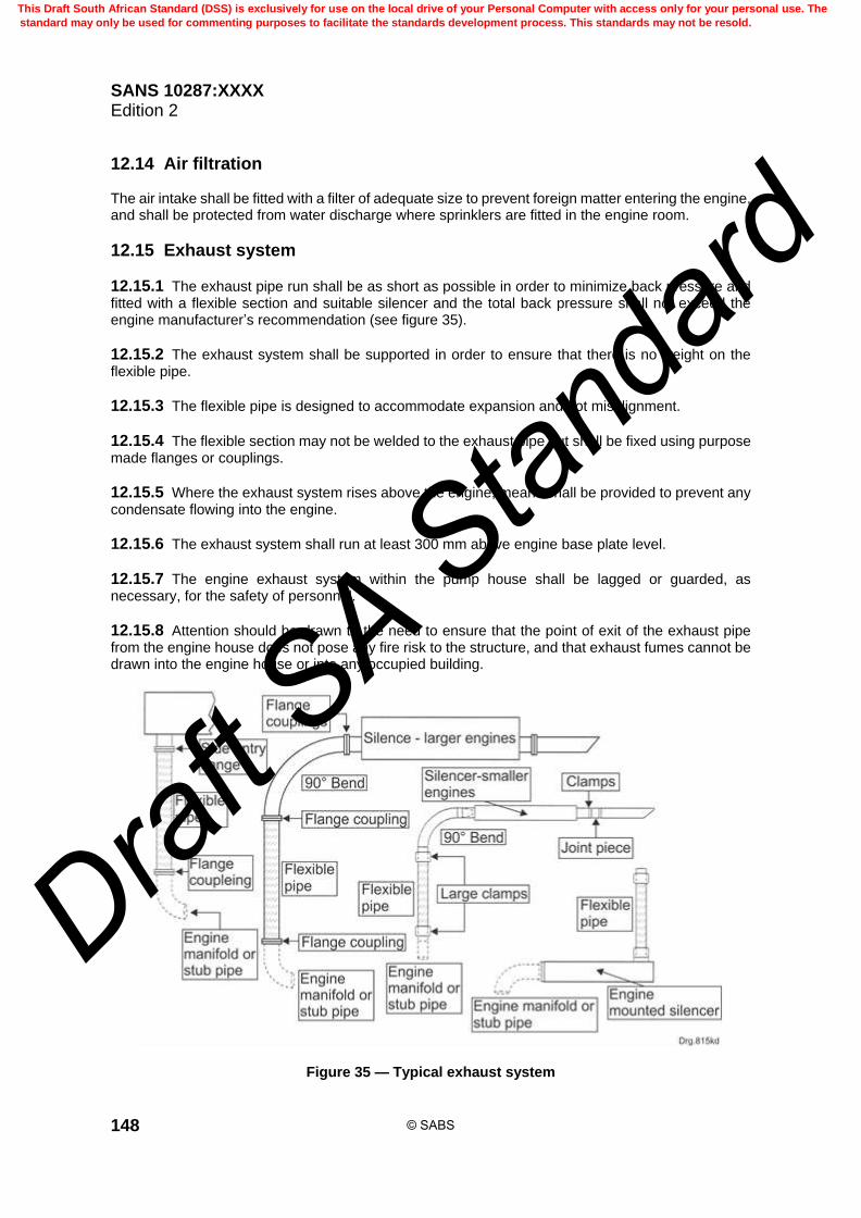
SANS 10287:XXXX Edition 2
148
12.14 Air filtration The air intake shall be fitted with a filter of adequate size to prevent foreign matter entering the engine, and shall be protected from water discharge where sprinklers are fitted in the engine room.
12.15 Exhaust system
12.15.1 The exhaust pipe run shall be as short as possible in order to minimize back pressure and fitted with a flexible section and suitable silencer and the total back pressure shall not exceed the engine manufacturer’s recommendation (see figure 35).
12.15.2 The exhaust system shall be supported in order to ensure that there is no weight on the flexible pipe.
12.15.3 The flexible pipe is designed to accommodate expansion and not misalignment.
12.15.4 The flexible section may not be welded to the exhaust pipe but shall be fixed using purpose made flanges or couplings.
12.15.5 Where the exhaust system rises above the engine, means shall be provided to prevent any condensate flowing into the engine.
12.15.6 The exhaust system shall run at least 300 mm above engine base plate level.
12.15.7 The engine exhaust system within the pump house shall be lagged or guarded, as necessary, for the safety of personnel.
12.15.8 Attention should be drawn to the need to ensure that the point of exit of the exhaust pipe from the engine house does not pose any fire risk to the structure, and that exhaust fumes cannot be drawn into the engine house or into any occupied building.
Figure 35 — Typical exhaust system
© SABS
This Draft South African Standard (DSS) is exclusively for use on the local drive of your Personal Computer with access only for your personal use. The
standard may only be used for commenting purposes to facilitate the standards development process. This standards may not be resold.
Draft S
A Stan
dard

SANS 10287:XXXX Edition 2
149
12.16 Engine shut down mechanism An extended accessible fuel stop control, clearly labelled shall be manually operated and return automatically to the starting position after use.
12.17 Fuel
12.17.1 The engine fuel shall comply with the engine manufacturer’s requirements.
12.17.2 Sufficient fuel to run the engine on full load for 6 h in addition to that in the engine fuel tank shall be kept on hand at all times. Where there are two diesel engine driven pumps they shall have separate fuel tanks and fuel feed pipes.
12.17.3 The capacity of the tank shall be sufficient to allow the engine to run on full load for 6 h and provision shall be made for the retention of any spilled fuel using a brick or similar material bund which shall contain not less than the contents of the fuel tank plus 10 %.
12.18 Fuel tank
12.18.1 The fuel tank shall be of welded steel and shall be located above ground in accordance with SANS 10131. The static head of the fuel tank when full shall not exceed the manufacturer’s pressure limit. The fuel tank shall be fitted with a drain valve of at least 20 mm diameter at the base of the tank.
12.18.2 The fuel tank may be fitted at the end of the pump set furthest away from the pump or outside the pump house but shall be positioned in a safe location in order to ensure there is convenient filling access and that the fuel line runs are as short as possible.
12.18.3 The tank shall be mounted higher than the engine fuel transfer pump and be provided with an indicator showing the level of the fuel in the tank.
12.18.4 The fuel level indicator shall not allow any leakage or spillage of fuel if broken.
12.18.5 Where there is more than one compression ignition engine-driven pump set there shall be a separate fuel tank and fuel feed pipe for each engine.
12.18.6 Fuel tanks shall not be fitted to or above either the engine or the batteries, neither shall they be positioned such that any spillage or leakage from the fuel tank can come into contact with any hot surface on the engine.
12.19 Fuel feed pipes
12.19.1 Any valve in the fuel feed pipe between the fuel tank and the engine shall not automatically close and shall be placed adjacent to the tank locked in the open position.
12.19.2 The fuel feed pipe shall be located at least 20 mm above the bottom of the fuel tank.
12.19.3 Pipes that carry lubricating oil or fuel shall be of flame-resistant reinforced flexible hose or suitable material listed for this service. Pipes shall not be made from plastic, rubber and pipe joints may not be soldered. Piping for any fuel line shall not be copper, cast iron, aluminium or galvanised tubing.
© SABS
This Draft South African Standard (DSS) is exclusively for use on the local drive of your Personal Computer with access only for your personal use. The
standard may only be used for commenting purposes to facilitate the standards development process. This standards may not be resold.
Draft S
A Stan
dard

SANS 10287:XXXX Edition 2
150
12.19.4 Pipe joints shall not be soldered and plastic tubing shall not be used.
12.20 Fuel system auxiliary equipment
12.20.1 The system consists of the following: a) a sludge and sediment trap; b) a readily visible fuel level gauge which shall not be of the glass or plastic tube type; c) an inspection and cleaning hole; d) a filter between the fuel tank and fuel pump mounted in an accessible position for cleaning; e) means to enable the entire fuel system to be bled of air; f) an air vent to prevent air locks or a vacuum forming; and g) means to fill the fuel tank. NOTE Damage of the fuel level gauge should not result in fuel spillage.
12.20.2 Air relief cocks and screwed plugs shall not be used.
12.21 Starting mechanism
12.21.1 Provision shall be made for two separate methods of engine starting as given in 12.21.2 to 12.21.9 (inclusive).
12.21.2 Two separate batteries of adequate capacity shall be provided for automatic and manual starting of the engine.
12.21.3 Where electric starting is used, the system shall operate from a battery supply recommended by the engine supplier.
12.21.4 Automatic starting shall be by means of a battery powered electric starter motor of the axial displacement type having no retaining catches or inertial features. The pinion shall rotate at reduced speed during the process of engagement with the flywheel gear ring, but during the initial engagement the pinion and armature shaft assembly shall mesh by moving axially towards the gear ring.
12.21.5 The starting sequence shall be initiated by a fall in pressure in the water supply pipe to the sprinkler installation, and repeat engagement facilities shall be provided should the starter pinion fail to engage with the engine flywheel ring.
12.21.6 When the engine fires, the starter motor pinion shall be withdrawn from the flywheel ring automatically by means initiated by a directly driven tacho generator or centrifugal speed switch or proximity switch.
12.21.7 Flexible drives shall not be used.
12.21.8 Battery charging, voltage generators, alternators and pressure switches on the engine lubricating system or water pump outlet, as a means of de-energizing the starter motor, shall not be used.
© SABS
This Draft South African Standard (DSS) is exclusively for use on the local drive of your Personal Computer with access only for your personal use. The
standard may only be used for commenting purposes to facilitate the standards development process. This standards may not be resold.
Draft S
A Stan
dard

SANS 10287:XXXX Edition 2
151
12.21.9 The starter motor in combination with each battery power supply shall have a design capability to rotate the engine for at least 3 min or 12 cycles of not less than 15 s cranking and not more than 6 s rest.
12.22 Batteries
12.22.1 Sealed maintenance-free batteries only are acceptable.
12.22.2 Batteries shall be readily accessible for servicing, positioned side by side and not stacked, located on stillages above the floor, secured against displacement and in a position where they will not be exposed to excessive temperature, vibration, mechanical damage or flooding water.
12.22.3 Current carrying parts, regardless of voltage, shall be at least 300 mm above finished floor level. Battery cables shall be at least 50 mm2 with a current carrying capacity of not less than 345 A and be fitted with suitable bolt through lug style terminals. Cable insulation shall be resistant to petrol, diesel, lubricating oils and diluted acids.
12.22.4 Batteries used for starting the diesel engine shall be located as close to the starter motor as possible. The length of the battery cables shall be as short as possible subject to a maximum allowance of 300 mm slack.
12.22.5 A built in hydrometer shall be provided to enable the state of the batteries to be determined. An information chart pertaining to the built in hydrometer shall be mounted on the battery case.
12.22.6 Each battery used for starting shall be of a type suitable to accommodate the method of charging with an expected life of approximately 4 years and not less than 3 years with a capacity to provide 3 min continuous cranking or 12 cycles of cranking a cold engine of 4 °C according to the method of starting employed.
12.22.7 Batteries not used for the automatic starting of diesel engine driven pumps, when fully charged and disconnected from the charger, shall be of sufficient capacity to monitor all specified circuits for at least 48 h, followed by 1 h in fully operational alarm condition.
12.22.8 Any battery used for an automatic power failure alarm shall not be used for the automatic starting of a diesel engine driven pump or for any purpose other than protection against fire.
12.22.9 All batteries within a pump house shall be engraved with the date of installation and shall be replaced at least every 3 years regardless of their condition.
12.23 Battery chargers
12.23.1 The means of charging the batteries shall be by a fully automatic continuously connected constant voltage, variable current up to 5 A charge having automatic trickle and boost charge facilities.
12.23.2 The equipment shall indicate that each battery and the relevant charger circuits are connected and carrying direct current.
12.23.3 The charging rate shall be set so that the battery does not gas excessively at any stage during the charging and the rate shall be automatically adjusted to suit the state of the battery.
12.23.4 The circuits of the batteries shall not be linked so that power may be transferred from one to the other.
12.23.5 The charger shall have self-resetting overload protection and shall be capable of operating on a short circuit.
© SABS
This Draft South African Standard (DSS) is exclusively for use on the local drive of your Personal Computer with access only for your personal use. The
standard may only be used for commenting purposes to facilitate the standards development process. This standards may not be resold.
Draft S
A Stan
dard

SANS 10287:XXXX Edition 2
152
12.23.6 The charger shall operate on a short circuit and operate even when the battery is totally flat.
12.23.7 The charger shall float a fully charged battery continuously.
12.23.8 The charger shall be designed to be protected against damage when an attempt is made to charge a reverse connected battery and shall initiate an alarm when the charger output has failed.
12.24 Tools A standard kit of tools as recommended by the engine manufacturer should be provided with the engine and kept on hand at all times where pumps are installed outside main urban centres.
12.25 Spare parts Spare parts recommended by the engine manufacturer should be supplied and kept on hand at all times when pumps are installed outside main urban centres.
12.26 Engine service
12.26.1 The diesel engine shall be serviced on an annual basis by a competent person who is experienced in the requirements relating to sprinkler installation pumped water supplies.
12.26.2 An identifying name and date tag stating when the engine was last overhauled shall be affixed to the engine.
12.27 Deration factors
12.27.1 The kilowatt output of the diesel engine as determined at sea level is initially derated for altitude. The resultant power available is then derated for temperature.
12.27.2 The deration factors given in tables 43 and 44 shall be allowed for when determining the kilowatt output of the diesel engine.
Table 43 — Diesel engine altitude duration factors
1 2
Type of engine Altitude deration
Naturally aspirated 3,5 % every 300 m above 150 m above sea level
Turbo charged 1,5 % every 300 m above 150 m above sea level
Inter-cooled turbo charged 1,0 % every 300 m above 150 m above sea level
Table 44 — Diesel engine temperature duration factors
1 2
Type of engine Temperature deration
Naturally aspirated 2,0 % every 5,5 °C above 30 °C ambient
Turbo charged 3,0 % every 5,5 °C above 30 °C ambient
Intercooled turbo charged 1,0 % every 5,5 °C above 30 °C ambient
© SABS
This Draft South African Standard (DSS) is exclusively for use on the local drive of your Personal Computer with access only for your personal use. The
standard may only be used for commenting purposes to facilitate the standards development process. This standards may not be resold.
Draft S
A Stan
dard
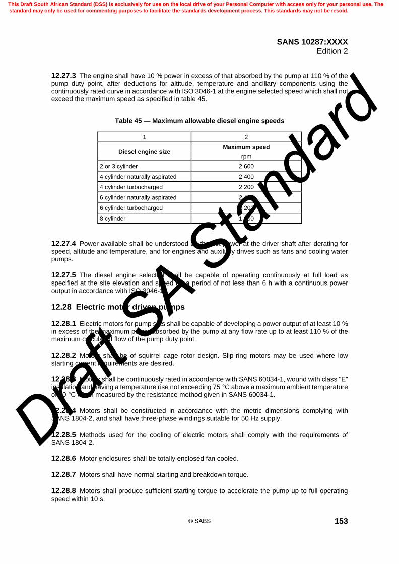
SANS 10287:XXXX Edition 2
153
12.27.3 The engine shall have 10 % power in excess of that absorbed by the pump at 110 % of the pump duty point, after deductions for altitude, temperature and ancillary components using the continuously rated curve in accordance with ISO 3046-1 at the engine selected speed which shall not exceed the maximum speed as specified in table 45.
Table 45 — Maximum allowable diesel engine speeds
1 2
Diesel engine size Maximum speed
rpm
2 or 3 cylinder 2 600
4 cylinder naturally aspirated 2 400
4 cylinder turbocharged 2 200
6 cylinder naturally aspirated 2 400
6 cylinder turbocharged 2 200
8 cylinder 1 800
12.27.4 Power available shall be understood as the net power at the driver shaft after derating for speed, altitude and temperature, and for engines and auxiliary drives such as fans and cooling water pumps.
12.27.5 The diesel engine selected shall be capable of operating continuously at full load as specified at the site elevation and speed for a period of not less than 6 h with a continuous power output in accordance with ISO 3046-1.
12.28 Electric motor driven pumps
12.28.1 Electric motors for pump sets shall be capable of developing a power output of at least 10 % in excess of the maximum power absorbed by the pump at any flow rate up to at least 110 % of the maximum calculated flow of the pump duty point.
12.28.2 Motors shall be of squirrel cage rotor design. Slip-ring motors may be used where low starting current requirements are desired.
12.28.3 Motors shall be continuously rated in accordance with SANS 60034-1, wound with class "E" insulation and having a temperature rise not exceeding 75 °C above a maximum ambient temperature of 40 °C when measured by the resistance method given in SANS 60034-1.
12.28.4 Motors shall be constructed in accordance with the metric dimensions complying with SANS 1804-2, and shall have three-phase windings suitable for 50 Hz supply.
12.28.5 Methods used for the cooling of electric motors shall comply with the requirements of SANS 1804-2.
12.28.6 Motor enclosures shall be totally enclosed fan cooled.
12.28.7 Motors shall have normal starting and breakdown torque.
12.28.8 Motors shall produce sufficient starting torque to accelerate the pump up to full operating speed within 10 s.
© SABS
This Draft South African Standard (DSS) is exclusively for use on the local drive of your Personal Computer with access only for your personal use. The
standard may only be used for commenting purposes to facilitate the standards development process. This standards may not be resold.
Draft S
A Stan
dard

SANS 10287:XXXX Edition 2
154
12.28.9 The starting torque of squirrel cage motors which are to be star or delta started shall be such that the starting torque produced in the star will be sufficient to accelerate the motor up to 75 % of full load speeds within 5 s. These accelerating times shall be achieved under open valve conditions against the specified motion and delivery pressure conditions.
12.28.10 Motors shall have the ends of each winding brought out to six terminals in the terminal box in accordance with SANS 1804-2 in the terminal box so that star or delta starting may be used if desired. Motors of 3 kW power or less shall have the ends of the three windings brought out to 3 terminals.
12.28.11 For the electrical operation of reduced voltage starts, timed automatic acceleration of the motor shall be provided and the period of acceleration shall not exceed 10 s.
12.28.12 Starting resistors shall be so designed as to permit a 15 s starting operation during each period of 80 s, for a period of at least 1 h. 12.28.13 Direct on-line starting is preferred, but star/delta, auto-transformer or stator and rotor type starters may be used if the supply authority, or the user (or both) insists because of limitations in the electric power supply. 12.28.14 The electric supply shall be obtained from a reliable source. 12.28.15 The electrical connections shall be such that a power supply is always available for the motor when the switches for the distribution of other power throughout the premises are open. Any switches on the power feed to the motor shall be clearly labelled as follows:
SPRINKLER PUMP MOTOR SUPPLY NOT TO BE SWITCHED OFF IN THE EVENT OF FIRE
12.28.16 A voltmeter and voltmeter selector switch and a fully integrated combined phase failure and phase reversal relay shall be provided in the controller to indicate there is a power supply available for the motor and the failure of any one phase of the AC supply. Such a phase failure/reversal relay shall not prevent the motor from attempting to start up nor shall it stop the motor while it is operating when any such phase failure/reversal occurs. 12.28.17 The controller shall be positioned in accordance with this standard so that it can be readily seen by maintenance personnel. 12.28.18 An automatic warning of power failure to the motor starting switches (in the case of AC, supply, of any one phase of the supply) shall be given visually and audibly as detailed in this standard. 12.28.19 Power for this warning system shall be taken from a separately switched sub-circuit to that feeding the motor alternatively, where the power is taken from a battery instead of the mains supply, the battery shall be trickle-charged and shall have an ampere hour capacity sufficient to provide 48 h of monitoring the complete system and 1 h of audible and visual alarm. 12.28.20 The power may not be provided from any battery used for automatic starting of a compression-ignition engine driven pump.
13 Electrical installations 13.1 General 13.1.1 Each pump room shall be equipped with a distribution board which shall be designed to interrupt the fault current. 13.1.2 The board shall be fitted with current limiting devices to ensure that the controller, monitoring panel or any other accessory which is connected to the switchboard is afforded suitable short circuit backup protection.
© SABS
This Draft South African Standard (DSS) is exclusively for use on the local drive of your Personal Computer with access only for your personal use. The
standard may only be used for commenting purposes to facilitate the standards development process. This standards may not be resold.
Draft S
A Stan
dard
SANS 10287:XXXX Edition 2
155
13.1.3 The distribution board shall be fitted with a separate switched fuse unit or circuit breaker of suitable rating to supply each of the following: a) the MV Electric drive controller; b) the compression-ignition engine drive controller; c) the jockey pump controller; d) the pump room monitoring panels; e) the pump room heating circuits; f) the pump room lighting circuits; g) the pump room plug circuits; and h) the accessories.
13.1.4 Taking of power for light and plug circuits or any other devices from drive controllers or monitoring panels is strictly prohibited.
13.1.5 Pump room electrical power connections from the distribution board to the pump drive controllers, annunciator panels, audible and visual signalling devices, pressure, flow and level monitors and interconnections between these items shall be designed for sprinkler use.
13.1.6 These power supplies shall be protected by means of suitably rated switch-fuse units or circuit breakers on the main HV or MV switchboards. These protective devices shall be clearly labelled as follows:
SPRINKLER PUMP POWER SUPPLY NOT TO BE SWITCHED OFF IN EVENT OF FIRE
13.1.7 The lettering shall be in 25 mm capitals.
13.1.8 The pump room MV switchboard, pump drive controllers, monitoring panels, etc., may be incorporated in one common panel within the pump room, provided that general arrangement is acceptable for sprinkler service.
13.1.9 Separately switched power sub-circuits shall be used to supply power for a) alarm devices connected to pump(s) and for any mains failure alarm system, and b) any pump that would be the first to come into operation because of a drop in the sprinkler
installation pressure and any mains-powered low-water pressure alarm system.
13.1.10 The indicating equipment shall be mains-powered fed by an uninterruptible power system.
13.2 Power supplies
13.2.1 Control and monitoring panels shall be designed for an electrical fault level of 31 MVA at 415 V, three-phase 50 Hz.
13.2.2 In the case of diesel engine drive controllers, the following shall apply: a) all DC electrical components shall be capable of functioning effectively at the reduced voltage
levels that occur during engine cranking; and
© SABS
This Draft South African Standard (DSS) is exclusively for use on the local drive of your Personal Computer with access only for your personal use. The
standard may only be used for commenting purposes to facilitate the standards development process. This standards may not be resold.
Draft S
A Stan
dard

SANS 10287:XXXX Edition 2
156
b) relays shall not chatter on drop-out and solid state circuits shall not "switch" under reduced voltage conditions.
13.2.3 The battery power supply for indicator panels or alarm systems shall not be supplied from the batteries provided to start the diesel engine(s).
13.3 Cables and wires Electric cables shall be a) suitable for electrical use in conjunction with sprinkler systems, b) selected, handled and installed in accordance with SANS 10198-2, SANS 10198-4 and
SANS 10198-8, c) protected, as far as possible, from direct exposure to fire, d) PVC-U-insulated or rubber-insulated and rubber-armoured, or enclosed in steel conduit, or
mineral-insulated and copper-sheathed, and e) steel wire armoured.
13.4 Wires
13.4.1 Electrical wires shall a) be single core, PVC-U-insulated, annealed copper conductors of 600 V grade in accordance with
SANS 1507-1, b) be continuously rated, and c) not use conductors that have fewer than seven strands or that are of cross-sectional area less than
2,5 mm2.
13.4.2 The following are normally deemed suitable for sprinkler use (depending on the particular application): a) wiring and wire ways that comply with the requirements of SANS 529 and SANS 950; b) cross-linked polyethylene-insulated (XLPE-insulated) electric cables that comply with the
requirements of SANS 1339.
13.4.3 In the case of cables to motors inside buildings, cables that are a) armoured and rubber-insulated in accordance with the requirements of SANS 1574-3, or b) enclosed in screwed steel conduit and that are rubber-insulated in accordance with the
requirements of SANS 1574-3 or that are mineral-insulated and copper-sheathed, and c) wire ways for electrical cables that comply with the requirements of SANS 10142-1.
13.4.4 Steel conduit shall be threaded in accordance with the requirements of SANS 1306-1.
13.4.5 External overhead cables shall not be used.
© SABS
This Draft South African Standard (DSS) is exclusively for use on the local drive of your Personal Computer with access only for your personal use. The
standard may only be used for commenting purposes to facilitate the standards development process. This standards may not be resold.
Draft S
A Stan
dard

SANS 10287:XXXX Edition 2
157
13.5 Circuit breakers and switches
13.5.1 Circuit breakers, isolators and switches shall be suitable for sprinkler use.
13.5.2 Moulded-case circuit breakers shall comply with the requirements of SANS 556-1 and earth-leakage protection units shall comply with the requirements of SANS 556-2-1 and SANS 556-2-2.
13.5.3 The following are deemed suitable for sprinkler use (depending on the particular application): a) electrical switches that comply with the requirements of SANS 60669-1; b) moulded-case circuit breakers that comply with the requirements of SANS 556-1; c) high-voltage AC circuit breakers; d) manually operated air break switches; e) AC disconnectors and earthing switches; and f) electrical high-voltage switches that comply with the requirements of SANS 62271-103
and SANS 62271-104.
13.6 Fuses, fuse cartridges and fused switchgear Fuses, fuse cartridges and fused switchgear shall be suitable for sprinkler use. Fused switchgear that complies with the requirements of SANS 62271-200 is normally deemed suitable for sprinkler use (depending on the particular application).
13.7 Busbars, contactors, fused switchgear and instruments
13.7.1 Busbars, contactors, fused switchgear and instruments shall be suitable for sprinkler use.
13.7.2 The following are deemed suitable for sprinkler use: a) Busbars that comply with the requirements of SANS 1195. b) Electrical terminals and connectors that comply with the requirements of SANS 1433-1 or
SANS 1433-2.
13.8 Power supplies
13.8.1 General 13.8.1.1 The equipment and materials shall be installed in accordance with SANS 10142-1. 13.8.1.2 Power supply voltages, currents and insulation levels for sprinkler installations shall comply with the requirements of SANS 1019. 13.8.1.3 Power supply circuits that serve sprinkler equipment and services shall function independently of any other main or sub-main circuits that do not serve the sprinkler installation. 13.8.1.4 Power for light and plug circuits or any other device shall not be taken from drive controllers or monitoring panels.
© SABS
This Draft South African Standard (DSS) is exclusively for use on the local drive of your Personal Computer with access only for your personal use. The
standard may only be used for commenting purposes to facilitate the standards development process. This standards may not be resold.
Draft S
A Stan
dard

SANS 10287:XXXX Edition 2
158
13.8.2 Main power supplies 13.8.2.1 The power supply shall be obtained from a public electricity supply or other suitable reliable source. 13.8.2.2 If the electricity supply is not taken from a public source, full particulars of the generating plant shall be agreed upon by all parties at the planning stage. 13.8.2.3 The fuel tanks of power-generating plant engines shall be kept fully filled when they are kept on stand-by. 13.8.2.4 Main power supplies for the installation shall be taken direct from a) the main high voltage (HV) switchboard for HV electric motor-drive controllers, and b) the main medium voltage (MV) switchboard for all MV equipment. 13.8.2.5 A typical diagram for the power supplies and the interconnecting of controllers and monitoring equipment for sprinkler installations is given in figure 36. 13.8.2.6 The power supplies for the pump room shall be derived direct from a) the main HV switchboard, in the case of the HV electric motor-driven controllers, and b) the main MV switchboard, in the case of the pump room MV switchboard. 13.8.2.7 Pump room electrical power connections from the distribution board to the pump drive controllers, annunciator or repeater panels, audible and visual signalling devices, pressure, flow and level monitors and interconnections between these items shall be such as to be suitable for sprinkler use. 13.8.2.8 The power supply circuit for electric motor-driven pumps shall be separate from all other circuits in the premises. 13.8.2.9 Power to drive the pumps shall be available at all times. 13.8.2.10 All wiring associated with the electric motor-driven pump shall be in accordance with SANS 10142-1.
13.8.3 Protection 13.8.3.1 The protection of the main and the control circuit power supplies shall be a) designed to suit a design fault level of 31 MVA at 415 V three-phase 50 Hz in situations of varying
fault levels, and b) provided with either high-rupturing capacity fuses of suitable rating or circuit breakers of suitable
rating and breaking capacity (or both). 13.8.3.2 Switches that control the power supplies shall be readily accessible to the fire brigade. 13.8.3.3 Power supply connections to any sprinkler equipment or services shall incorporate suitable isolating protective devices and these devices shall be secured against unauthorized operation.
© SABS
This Draft South African Standard (DSS) is exclusively for use on the local drive of your Personal Computer with access only for your personal use. The
standard may only be used for commenting purposes to facilitate the standards development process. This standards may not be resold.
Draft S
A Stan
dard
SANS 10287:XXXX Edition 2
159
13.8.3.4 Separately switched fuse units or circuit breakers of suitable rating shall be provided for all electric drive controllers, diesel engine drive controllers, jockey pump drive controllers, pump room monitoring panel(s), pump room heating and lighting circuits and plug circuits. 13.8.3.5 Power supply connections to the pump room shall be protected by means of suitably rated switch fuse units or circuit breakers to interrupt the fault current on the HV or MV switchboards. 13.8.3.6 The following shall apply in the case of electric motor-driven pumps: a) the electricity supply to motors shall incorporate fuses of high-rupturing capacity that are capable
of carrying the stalled motor current for a period of not less than 75 % of the period needed for the motor windings to fail;
b) any no-volt release mechanism shall be of the automatic resetting type so that, on restoration of
the supply, the motor can be restarted automatically if the trunk main pressure falls; and c) magnetic and thermal overload trips shall be not be used.
13.8.4 Control panels 13.8.4.1 Control circuit power supplies shall not exceed an AC voltage of 110 VAC/DC and shall be derived from a separate, suitably rated double-wound air-cooled transformer within the enclosure of each controller, monitoring panel or power supply point. 13.8.4.2 Current-carrying parts of any control circuits and panels shall be at least 300 mm above floor level.
13.8.5 Electrical earthing 13.8.5.1 All exposed metalwork in installations shall be efficiently earthed to prevent the metalwork from becoming electrically charged. 13.8.5.2 Sprinkler pipework shall be not used as a means of earthing electrical equipment. 13.8.5.3 Electrical equipment below sprinkler installations shall have normal earthing and overload protection. 13.8.5.4 Sprinkler installation metalwork and metal wire-ways for electric cables shall be efficiently connected to the main earthing terminal of the electrical installation.
13.8.6 Cables and cable routes for electrically driven pumps 13.8.6.1 External overhead cables shall be not used for electrically driven pumps and all cables shall be protected against fire and mechanical damage. 13.8.6.2 If there are two or more electric motor driven pumps, failure (owing to mechanical breakdown or fire damage) of equipment or cables that supply any one pump shall not affect the supply to other pump. 13.8.6.3 The supply to the pump controller shall be solely for use of the sprinkler pump set and separate from all other connections. 13.8.6.4 Where permitted by the electrical supplier, the electric supply to the pump controller shall be taken from the input side of the main switch on the incoming supply to the premises and where this is not permitted, by a connection from the main switch.
© SABS
This Draft South African Standard (DSS) is exclusively for use on the local drive of your Personal Computer with access only for your personal use. The
standard may only be used for commenting purposes to facilitate the standards development process. This standards may not be resold.
Draft S
A Stan
dard

SANS 10287:XXXX Edition 2
160
13.8.6.5 Cables shall be run outside the building to protect them from exposure to fire, or through those parts of the building where the fire risk is negligible and that are separated from any significant fire risk by walls, partitions or floors with a fire-resistance rating of at least 60 min for ordinary hazard occupancies and 90 min for high hazard risks, or they shall be given additional direct protection or be buried. 13.8.6.6 Cables shall be in single lengths with no joins.
© SABS
This Draft South African Standard (DSS) is exclusively for use on the local drive of your Personal Computer with access only for your personal use. The
standard may only be used for commenting purposes to facilitate the standards development process. This standards may not be resold.
Draft S
A Stan
dard

SANS 10287:XXXX Edition 2
161
Figure 36 — Typical diagram of the power supplies for a pump house
© SABS
This Draft South African Standard (DSS) is exclusively for use on the local drive of your Personal Computer with access only for your personal use. The
standard may only be used for commenting purposes to facilitate the standards development process. This standards may not be resold.
Draft S
A Stan
dard

SANS 10287:XXXX Edition 2
162
14 Pump drive controllers
14.1 General
14.1.1 Each pump shall have its own controller which shall be specifically designed for sprinkler fire pump service and verified by a testing authority.
14.1.2 All pump manufacturers shall use the panels which are approved in conjunction with their units.
14.1.3 A certificate of acceptance issued by a testing authority shall be required for every panel and any modifications without prior approval will invalidate the certificate.
14.1.4 The controller shall be completely assembled, wired and tested by the manufacturer and an independent authority before shipment from the factory to site.
14.1.5 The controller shall be labelled in accordance with this standard and the nameplate shall show plainly the name of the manufacturer, the identifying designation, the complete electrical rating, and the certificate of approval number.
14.1.6 The sprinkler installer shall make the necessary arrangements for the services of a manufacturer’s representative, when needed, for installation and adjustment of the equipment.
14.2 Labels
14.2.1 Labels shall consist of a composite red/white/red plastic sandwich type to show white letters on a red background.
14.2.2 Anodized aluminium type labels with red background are acceptable.
14.2.3 Label descriptions shall be in both English and any other required official language.
14.2.4 The letter and numeral sizes which shall be used for labels are shown in table 46.
Table 46 — Pump drive controller labels
1 2
Label type Letter height
mm
Main panel designation 12
Individual component designations 6
Small component designations 3
Control/signal device designations 2,5
14.2.5 Plastic embossed stick-on tape labels shall not be used.
14.2.6 Labels for control fuses shall indicate function and fuse rating.
© SABS
This Draft South African Standard (DSS) is exclusively for use on the local drive of your Personal Computer with access only for your personal use. The
standard may only be used for commenting purposes to facilitate the standards development process. This standards may not be resold.
Draft S
A Stan
dard

SANS 10287:XXXX Edition 2
163
14.2.7 Each operating component of the controller shall be clearly marked to indicate the identifying letter or number referenced to the wiring diagram and the markings shall be located so as to be visible after installation.
14.3 Starting and control
14.3.1 In the control circuit there shall be provided a pressure actuated switch with high and low calibrated adjustments or two pressure actuated switches, one having high and the other having low calibrated adjustments and responsive to water pressure in the fire protection system.
14.3.2 Suitable means shall be made for relieving pressure to the pressure actuated switch, to test the operation of the controller and the pump.
14.3.3 When the pump supplies special water control equipment (such as deluge valves and dry pipe valves), and it is desired to start the pump before the pressure actuated switch(es) would do so, the controller shall be equipped to start the pump upon operation of the fire detection equipment.
14.3.4 The controller shall be wired for manual shut down.
14.3.5 Shut down shall be accomplished by operation of the stop/reset push button on the outside of the control enclosure and, in the case of automatic controllers, shall return the controller to full automatic position.
14.4 Location of controller
14.4.1 The controller shall be located as close as it is practical to the motor/engine it controls and shall be within sight of the motor/engine.
14.4.2 Diesel engine controllers shall, where possible, be located in a position whereby the fuel shut off lever and controller panel buttons can be accessed simultaneously.
14.4.3 The controller shall be so located or so protected that it will not be damaged by water escaping from the pump or pump connection.
14.5 Construction
14.5.1 All controller equipment shall be incorporated within a total enclosed, damp, dust and flash proof enclosure.
14.5.2 All equipment except those items fixed in the door shall be mounted on a removable 2 mm thick rolled mild steel chassis plate which shall be folded and braced to ensure rigidity.
14.5.3 The controller enclosure shall be constructed from 2 mm thick cold rolled mild steel and shall be equipped with a hinged door supported on robust hinges and secured by a sufficient number of substantial catches to ensure proper sealing of the gasket.
14.5.4 The door shall be fitted with a non-deteriorating gasket made from butyl sponge rubber or similar material.
14.5.5 The following shall be provided in a suitable pocket permanently secured inside the enclosure door: a) wiring diagrams with clearly identifiable letters and numbers for all components and wires;
© SABS
This Draft South African Standard (DSS) is exclusively for use on the local drive of your Personal Computer with access only for your personal use. The
standard may only be used for commenting purposes to facilitate the standards development process. This standards may not be resold.
Draft S
A Stan
dard

SANS 10287:XXXX Edition 2
164
b) complete component schedule giving wiring diagram reference, make, type, size and supplier; and c) operation and maintenance instructions.
14.5.6 Complete operating instructions, in English and any official language that may be required, a wiring diagram and a component schedule shall be affixed in the pump room in a suitable weather proof mounting.
14.5.7 Electrical terminals and both ends of all wires shall be plainly marked to correspond with the as-built wiring diagrams for the controller.
14.6 Controller panel testing
14.6.1 General 14.6.1.1 Each complete controller panel shall be cyclically tested at a suitable test facility and witnessed by a recognised competent person familiar with the requirements of fixed fire protection systems. 14.6.1.2 Adequate notification and copies of the detailed information shall be circulated to the competent person in order that they may witness the test. Copies of a certificate showing the records of the test which shall be conducted as specified in 14.6.2 to 14.6.4 shall be supplied to the relevant authority.
14.6.2 Testing of electric motor driven fire pump controllers A minimum of 160 cycles of each test shall be conducted. Should the cycle be interrupted or failure of a component take place, the testing shall be restarted.
Tests performed per cycle Test 1:
a) Initiate a fire condition via the pressure switch;
b) Monitor fire and pump run signals only;
c) Initiate the Stop/Reset button;
d) No signals shall be received at this stage;
e) Test complete. Test 2:
a) Initiate a fire condition via the Test push button;
b) Monitor fire and pump run signals only;
c) Initiate the Stop/Reset button;
d) No signals shall be received at this stage;
e) Test complete.
© SABS
This Draft South African Standard (DSS) is exclusively for use on the local drive of your Personal Computer with access only for your personal use. The
standard may only be used for commenting purposes to facilitate the standards development process. This standards may not be resold.
Draft S
A Stan
dard

SANS 10287:XXXX Edition 2
165
Test 3:
a) Initiate the Emergency Start push button;
b) Monitor the pump run signal only;
c) Initiate the Stop/Reset button;
d) No signals shall be received at this stage;
e) Test complete. Test 4:
a) Initiate a fault on the Delta Contactor;
b) Initiate a fire condition via the pressure switch;
c) Monitor fire and pump fail signals only;
d) Remove the fault condition on the Delta Contactor;
e) Monitor Fire and Pump Fail signals only;
f) Initiate the Stop/Reset button;
g) No signals shall be received at this stage;
h) Test complete. Test 5:
a) Initiate a Mains Fail;
b) Monitor Mains Fail and Control Circuit Fail signals only;
c) Remove Mains Fail condition;
d) No signals shall be received at this stage;
e) Test complete. Test 6:
a) Initiate a Control Circuit Fail;
b) Monitor Control Circuit Fail signal only;
c) Remove Control Circuit Fail condition;
d) No signals shall be received at this stage;
e) Test complete.
© SABS
This Draft South African Standard (DSS) is exclusively for use on the local drive of your Personal Computer with access only for your personal use. The
standard may only be used for commenting purposes to facilitate the standards development process. This standards may not be resold.
Draft S
A Stan
dard

SANS 10287:XXXX Edition 2
166
14.6.3 Testing of diesel engine driven fire pump controllers A minimum of 80 cycles of each test shall be conducted. Should the cycle be interrupted or failure of a component take place, the testing shall be restarted.
Tests performed per cycle Test 1: Fire condition through pressure switch:
a) Monitor for Fire, Pump Run signal;
b) Monitor 220 volt output for pump house extraction fan; Test 2: Fire condition through push buttons:
a) Monitor for Fire, Pump Run signal;
b) Monitor 220 volt output for pump house extraction fan; Test 3: Fire condition through pressure switch with Mains Fail condition:
a) Monitor for Fire, Pump Run, Mains Fail and Battery Charger Fail signals;
b) Initiate a Low Oil condition;
c) Monitor for Fire, Pump Run, Mains Fail, Battery Charger Fail and Low Oil signals; Test 4: Fire condition through pressure switch with Mains Fail condition:
a) Monitor for Fire, Pump Run, Mains Fail and Battery Charger Fail signal;
b) Initiate a High Engine Temperature condition;
c) Monitor for Fire, Pump Run, Mains Fail, Battery Charger Fail and Low Oil signals; Test 5: Fire condition through pressure switch with 300 rpm crank condition:
a) Monitor for 15 seconds crank and 6 seconds dwell time;
b) Monitor alternating crank cycles;
c) Monitor for Fire, Mains Fail and Battery Charger Fail signals;
d) Monitor for Pump Fail signal after six start attempts;
e) Monitor for Fire, Mains Fail and Battery Charger Fail signals;
© SABS
This Draft South African Standard (DSS) is exclusively for use on the local drive of your Personal Computer with access only for your personal use. The
standard may only be used for commenting purposes to facilitate the standards development process. This standards may not be resold.
Draft S
A Stan
dard

SANS 10287:XXXX Edition 2
167
f) Initiate Emergency Start 1;
g) Monitor for Fire, Pump Run, Mains Fail and Battery Charger Fail signals;
Test 6: Fire condition through pressure switch with 300 rpm crank condition:
a) Monitor for 15 seconds crank and 6 seconds dwell time;
b) Monitor alternating crank cycles;
c) Monitor for Fire, Mains Fail and Battery Charger Fail signals;
d) Monitor for Pump Fail signal after six start attempts;
e) Monitor for Fire, Mains Fail and Battery Charger Fail signals;
f) Initiate Emergency Start 2;
g) Monitor for Fire, Pump Run, Mains Fail and Battery Charger Fail signals;
Test 7: Initiate a fire condition through pressure switch continuously:
a) Monitor for Fire and Pump Run signals;
b) Initiate Reset button;
c) Monitor for Fire, and Pump Run Signals; Test 8: De-energise 220 volt AC and 12 or 24 volt DC control circuit supply: Monitor for mains fail, battery charger fail and control circuit fail signals.
14.6.4 Testing of annunciator panels 14.6.4.1 A minimum of 160 cycles of each test shall be conducted. Should the cycle be interrupted or failure of a component take place, the testing shall be restarted. 14.6.4.2 Each signal for the diesel engine driven pump and the electric motor driven pump shall be mimicked. 14.6.4.3 The annunciator shall be checked for the following alarm signals: a) a fire condition shall initiate a continuously sounding sired and strobe light or beacon; b) a pump failure condition shall initiate an intermittent sounding siren and strobe light or beacon; c) pump running or Emergency Start shall initiate a strobe light or beacon; d) mains failure shall initiate an electric motor driven alarm bell and strobe light or beacon; e) controller circuit failure shall initiate an electric motor driven alarm bell and strobe light or beacon;
© SABS
This Draft South African Standard (DSS) is exclusively for use on the local drive of your Personal Computer with access only for your personal use. The
standard may only be used for commenting purposes to facilitate the standards development process. This standards may not be resold.
Draft S
A Stan
dard
SANS 10287:XXXX Edition 2
168
f) battery charger failure shall initiate an electric motor driven alarm bell and strobe light or beacon; g) Low Oil Pressure shall initiate an electric motor driven alarm bell and strobe light or beacon; and h) Pump House Protection shall initiate a continuously sounding siren and strobe light or beacon.
14.7 Electric motor drive controllers
14.7.1 The controller shall be labelled: ELECTRIC MOTOR DRIVEN PUMP CONTROLLER.
14.7.2 All busbars and connections shall be readily accessible for maintenance work after installation of the controller without disconnecting the external circuit conductors.
14.7.3 Circuits which are depended upon for proper operation of the controller shall not have over current protective devices connected in them. Maximum short circuit protection with current limiting facilities shall, however, be provided for all circuits.
14.7.4 All switching equipment for manual use in connecting or disconnecting or starting or stopping the motor shall be externally operable.
14.7.5 A manually operated fused isolating switch shall be mounted within the controller enclosure.
14.7.6 The switch shall be equipped with one fuse in each phase and the switch rating shall be determined by the fuse size.
14.7.7 The fuses shall comply with this standard and the fuse rating shall be in accordance with table 47, irrespective of method of starting.
14.7.8 High rupturing capacity (HRC), cartridges of a suitable rating mounted in insulated removable fuse holders, complying with this standard shall be provided for the protection of each branch circuit conductor.
14.7.9 The removal or blowing of any HRC fuse shall initiate an alarm or fault condition at the alarm annunciator panel.
14.7.10 If used, one complete set of spare main motor circuit and control circuit HRC fuse cartridges shall be secured on brackets inside the enclosure door which are approved.
14.7.11 The ampere rating of the switch shall be determined by the fuse size but shall be at least 115 % of the name plate current rating of the motor.
14.7.12 No over current protective devices shall be installed in the motor circuit.
14.7.13 The motor starter shall be of the AC automatic type, incorporating magnetically operated air break contactors.
14.7.14 For electrical operation of reduced voltage starts, timed automatic acceleration of the motor shall be provided and the period of acceleration shall not exceed 10 s.
14.7.15 Starting resistors shall be designed to permit 15 s starting operation in each 80 s for a period of not less than 1 h.
© SABS
This Draft South African Standard (DSS) is exclusively for use on the local drive of your Personal Computer with access only for your personal use. The
standard may only be used for commenting purposes to facilitate the standards development process. This standards may not be resold.
Draft S
A Stan
dard

SANS 10287:XXXX Edition 2
169
14.7.16 Direct on-line starting is preferred but star or delta, auto-transformer or stator and rotor type starters may be used if the supply authority or user (or both) insist on this because of electric power supply limitations. The installer shall establish what type of starting is permissible.
14.7.17 A fully integrated combined phase failure and phase reversal relay shall be incorporated in the panel. Electrically separate contacts shall be provided on the phase failure relay and these shall be wired out to clearly identified terminals on the controller.
14.7.18 Such a phase failure/reversal relay shall not prevent the motor from attempting to start nor shall it stop the motor while it is operating when any such phase failure/reversal occurs.
14.7.19 A voltmeter complete with fuses and a voltmeter selector switch arranged to select phase to phase and phase to neutral readings shall be provided.
14.7.20 An ammeter, 3 current transformers and a selector switch shall be fitted on the controller connected in such a way as to test each phase in order to check the loading of the motor.
14.7.21 For motors in excess of the ratings in table 47, the manufacturer shall submit details of a proposed back up protection for approval to the relevant independent panel test facility.
14.7.22 The controller shall be fitted with electrically separate potential free contacts to make provision for the following conditions to be maintained: a) fire alarm; b) power failure, (main electrical supply); c) pump failure; d) pump running; and e) control circuit failure, (wired from the end of the control circuit).
14.7.23 Indication on the controller shall be in the form of indicating lamps in duplicate to show the following: a) fire alarm; b) pump failure to start; and c) pump running.
© SABS
This Draft South African Standard (DSS) is exclusively for use on the local drive of your Personal Computer with access only for your personal use. The
standard may only be used for commenting purposes to facilitate the standards development process. This standards may not be resold.
Draft S
A Stan
dard

SANS 10287:XXXX Edition 2
170
Table 47 — High rupturing capacity fuse rating selection chart
1 2 3 4
On 400 VAC On 525 VAC
Maximum motor size
Fuse rating Maximum motor size Fuse rating
kW A kW A
1,5 16 1,5 16
2,2 16 2,2 16
3,0 20 3,0 16
4,0 25 4,0 20
5,5 32 5,5 25
7,5 40 7,5 32
9,2 50 9,2 40
11 63 11 40
15 80 15 50
18,5 80 18,5 63
22 80 22 80
30 125 30 100
37 160 37 125
45 160 45 125
55 200 55 160
75 250 75 200
90 315 90 250
110 355 110 315
132 400 132 355
150 400 150 355
160 400 160 355
185 500 185 400
200 500 200 400
220 500 220 400
250 630 250 500
260 630 260 500
300 800 300 500
315 800 315 630
330 800 330 630
14.7.24 A reset push button shall be fitted on the controller to reset the controller.
14.7.25 The controller shall latch on to a starting signal until the reset push button is pressed.
14.7.26 A push button shall be fitted on the controller for emergency starting which will bypass the automatic starting circuit.
14.7.27 A separate test push button shall be fitted on the controller to initiate the automatic starting sequence operation.
© SABS
This Draft South African Standard (DSS) is exclusively for use on the local drive of your Personal Computer with access only for your personal use. The
standard may only be used for commenting purposes to facilitate the standards development process. This standards may not be resold.
Draft S
A Stan
dard

SANS 10287:XXXX Edition 2
171
14.7.28 Should the power requirements of the fire pump be such that it cannot be started at the same time as the plant is operating, an electrically separate contact and timer shall be provided on the controller to initiate tripping of the plant circuit breaker before power is applied to the motor terminals.
14.8 Compression-ignition engine drive controllers
14.8.1 The controller shall be labelled: DIESEL ENGINE DRIVEN PUMP CONTROLLER.
14.8.2 All switching equipment for manual use in connecting or disconnecting or starting or stopping the engine shall be externally operable.
14.8.3 A manually operated isolating switch shall be mounted within the controller enclosure.
14.8.4 Fuses for protection of both the AC and DC circuits shall be provided and shall comply with this standard and the fuse rating shall be in accordance with table 47.
14.8.5 High rupturing capacity cartridge fuses of suitable rating mounted in insulated removable fuse holders shall be provided for the protection of each branch circuit conductor.
14.8.6 The removal or blowing of any HRC fuse shall initiate an alarm or fault condition at the annunciator panel.
14.8.7 One complete set of spare HRC fuse cartridges shall be secured on brackets inside the enclosure door which are approved.
14.8.8 Automatic starting shall be initiated by one of two external monitoring devices wired in parallel and the starting components shall be arranged to crank for a maximum period of 15 s and dwell for a period of not more than 6 s. Both time periods shall be adjustable and set to suit engine and site conditions.
14.8.9 A pre-settable counter arranged to count each cranking period shall be provided and shall be capable of being pre-set for up to 9 counts, but shall normally be pre-set for 6 counts. If the engine has not started after the pre-set number of counts, the cranking shall be stopped and the pump failure indication and alarm shall be initiated. Only actual cyclic counters shall be used. A timer set for the overall calculated time for the pre-set number of starts shall not be used.
14.8.10 The components shall be arranged to connect each of the two batteries to the engine starter motor on alternate cranking cycles and so designed that the first cycle of a fresh attempted start shall alternate between one battery and the other.
14.8.11 A suitable voltage relay shall be connected across the load side of the main fuses and electrically separate contacts on this relay shall be wired out to clearly identified terminals for initiating the power failure alarm.
14.8.12 An AC voltmeter shall be provided to indicate the input voltage to the controller.
14.8.13 A DC voltmeter shall be provided to indicate the terminal voltage of each battery.
14.8.14 A DC ammeter shall be provided to indicate the charging rate of each battery.
© SABS
This Draft South African Standard (DSS) is exclusively for use on the local drive of your Personal Computer with access only for your personal use. The
standard may only be used for commenting purposes to facilitate the standards development process. This standards may not be resold.
Draft S
A Stan
dard

SANS 10287:XXXX Edition 2
172
14.8.15 Electrically separate potentially free contacts wired out to clearly identified terminals shall be provided for the following conditions to be monitored: a) fire alarm; b) power failure (battery charger electrical supply); c) pump failure; d) pump running; e) low oil pressure; f) charger failure (from both charger outputs in parallel); g) control circuit failure (from the end of the control circuit); and h) electronic governor communication failure.
14.8.16 Duplicate indicating lamps shall be provided to show the following: a) fire alarm; b) pump failure; c) pump running; and d) low oil pressure.
14.8.17 A reset push button shall be provided to reset the controller.
14.8.18 The controller shall latch on to a starting signal until the reset push button is pressed.
14.8.19 One "emergency start" push button shall be provided for each battery and the circuitry shall be arranged so that each push button will bypass the automatic starting circuit and will energize its associated starter motor solenoid. It shall be possible to depress both push buttons and apply power from both batteries simultaneously to the starter motor.
14.8.20 An adjustable voltage sensitive device shall be provided to sense the potential generated by the tacho generator referred to in 12.21.6. One set of normally open contacts of one voltage sensitive relay shall be wired in parallel with that of the other relay to initiate the pump running relay as follows: a) each engine shall be fitted with two tacho generators of different drive points on the engine; or b) a combination of one tacho generator and one proximity sensor may be fitted to the engine to
monitor engine motion. Where such a sensor is used, the controller panel shall be fitted with a matching sensing relay with one set of normally open contacts to be wired in parallel to those of the voltage sensitive relay to initiate the pump running relay.
14.8.21 Manual isolating or selector (or both) switches in the battery to engine starter motor circuits shall not be used.
14.8.22 A separate test button shall be provided to initiate the automatic starting sequence.
© SABS
This Draft South African Standard (DSS) is exclusively for use on the local drive of your Personal Computer with access only for your personal use. The
standard may only be used for commenting purposes to facilitate the standards development process. This standards may not be resold.
Draft S
A Stan
dard

SANS 10287:XXXX Edition 2
173
14.8.23 Controllers mounted on the engine bedplate shall be supported by a substantial frame securely bolted to the engine bedplate and the controller shall be secured to this frame by means of resilient mountings which are approved.
14.8.24 Plug-in components such as fuses, relays, and PC boards, in controllers which are mounted on the engine bedplates shall be provided with suitable spring clips or securing facilities to prevent unplugging due to vibration.
14.8.25 The removal of any relay shall initiate either a "Fault" condition or the "Control Circuit Failure" alarm at the annunciator panel.
14.8.26 Batteries shall be mounted and securely clamped on stands or stillages and located in a readily accessible position where the likelihood of contamination by oil, fuel, damp, pump set cooling water or being damaged by vibration, is unlikely.
14.8.27 The battery shall be installed as close to the starter motor as possible to minimize voltage drops between the battery and starter motor terminals. The batteries shall be mounted on a wooden base.
14.8.28 Continuously rated, heavy current solenoid operated contactors for connecting the battery to the engine starter motor shall be located on the engine or bedplate immediately adjacent to the engine starter motor or batteries.
14.8.29 All DC electrical components shall be capable of functioning effectively at the reduced voltage levels that exist during cranking. Relays shall not chatter or drop out and solid state circuits shall not "switch" under these low voltage conditions.
14.8.30 The battery voltage shall be as specified by the engine manufacturers. 24 V batteries are preferred, but 12 V batteries are acceptable.
14.8.31 The control circuit shall be arranged to operate across the full battery voltage. Connections for any reduced voltage shall not be taken by tapping-off cells in the battery.
14.8.32 The controller shall be equipped with one battery charger in accordance with this standard for each battery.
14.9 Electric motor driven jockey pump controllers
14.9.1 The jockey controller shall comply with clause 13 and 14.7.
14.9.2 The controller shall be labelled: JOCKEY PUMP CONTROLLER.
14.9.3 Starting and stopping of the motor shall be initiated by a pressure actuated switch with high and low calibrated adjustments and which is responsive to water pressure in the fire protection system.
14.9.4 Suitable means shall be made for relieving pressure to the pressure actuated switch to test the operation of the controller and the pump.
14.9.5 The controller shall be fitted with the following: a) suitably rated triple pole isolators with auxiliary contacts as may be necessary; b) suitably rated contactors;
© SABS
This Draft South African Standard (DSS) is exclusively for use on the local drive of your Personal Computer with access only for your personal use. The
standard may only be used for commenting purposes to facilitate the standards development process. This standards may not be resold.
Draft S
A Stan
dard

SANS 10287:XXXX Edition 2
174
c) adjustable, ambient temperature compensated thermal overload relay for motor protection; and d) hand or auto-selector switch.
14.9.6 A timer with a 0 s to 30 s setting normally set to 20 s shall be used.
14.9.7 When the hand or auto-selector switch is in the hand position, the pump shall run continuously, and when the switch is in the auto position, the pump shall start and stop automatically under the control of the pressure switch.
14.9.8 Selector switches incorporating off positions shall not be used.
14.10 Annunciators for sprinkler pump room installations
14.10.1 The controller shall be labelled: PUMP HOUSE ANNUNCIATOR PANEL.
14.10.2 Each pump room shall have its own annunciator panel, audible and visual signalling devices and, where required, a repeater panel, all of which shall be approved for sprinkler use.
14.10.3 The panel manufacturer’s audible and visual signalling devices such as sirens, bells, hooters, beacons and lamps shall be accepted for use in conjunction with annunciator and repeater panels which are approved.
14.10.4 The sprinkler installer shall make the necessary arrangements for the services of a manufacturer’s representative, when needed, for installation and adjustments of annunciator and repeater panels and equipment.
14.10.5 Each component of the alarm or annunciator or repeater panel (or both) shall be clearly marked to indicate the identifying letter or number referenced to the wiring diagram and the markings shall be located so as to be permanently visible after installation.
14.10.6 All circuits, including the pressure switches and battery connections, shall be monitored as follows: a) open circuits shall indicate a "fault" condition; b) high impedance closed circuits shall constitute a normal condition, and no indication is required;
and c) short circuits shall indicate an "alarm" or "warning" condition.
14.10.7 A "fault", "alarm" or "warning" as described in 14.9.7 shall initiate the audible alarm which shall be silenced by means of an "accept" push button.
14.10.8 When a "fault", "alarm" or "warning" condition occurs, the circuit annunciator shall flash on and off until the signal has been accepted, when the annunciator will change from a flashing to a steady visual signal. When the circuit is restored to a normal condition as described in 14.9.8, the steady signal shall reset.
14.10.9 A first alarm condition shall cause the audible alarm to sound and, after acceptance, a second alarm shall again cause the audible alarm to sound. Systems in which the audible alarm is negated after acceptance shall not be used.
14.10.10 Where a pump house repeater panel is required, it shall be mounted in a position which is approved at a manned location in the plant or on the premises.
© SABS
This Draft South African Standard (DSS) is exclusively for use on the local drive of your Personal Computer with access only for your personal use. The
standard may only be used for commenting purposes to facilitate the standards development process. This standards may not be resold.
Draft S
A Stan
dard

SANS 10287:XXXX Edition 2
175
14.10.11 The two audible and one visual signalling device shall be mounted immediately outside the pump room in a position which is approved.
14.10.12 The audible range of all audible signalling devices shall be adequate to suit the distance to be covered and the noise environment of the location with a signal strength of not less than 75 dB. Where this is not practical, a repeater panel shall be installed at a permanently manned position.
14.10.13 A steady audible alarm and a flashing visual alarm shall be initiated when a "fire" condition exists.
14.10.14 An intermittent audible alarm shall be initiated when a "pump failure" condition exists.
14.10.15 A steady audible alarm bell and a flashing visual alarm shall be initiated when a "power failure" condition exists.
14.10.16 The "Pump house protection" alarm shall initiate the steady audible and flashing visual alarms.
14.10.17 The signalling devices shall be suitable for operation from the battery powering the annunciator system.
14.10.18 Battery chargers and batteries shall not be housed in the same enclosure as the annunciator or repeater panels.
14.10.19 The charger and batteries may be housed in a common enclosure but in separate compartments suitably divided and sealed to ensure that charger components are not subjected to battery fumes.
14.11 Pressure switches, flow switches, patents or specialized valves and components (approval) These components shall all be approved for sprinkler installation use.
14.12 Pump house remote alarm notification and data logger module
14.12.1 General Each pump house shall be equipped with a remote alarm notification and data logger module to enable remote monitoring of the pump house events and retrieval of data.
14.12.2 Functionality 14.12.2.1 The data logging module shall have a) the ability to locally log all events that occur within the pump house facility, b) the ability to remotely log all events that occur within the pump house facility, c) the ability to send pump house alarms to personnel via SMS or pager, and d) the ability to send pump house alarms to a computer via SMS or pager. 14.12.2.2 The remote alarm module device shall be located inside the pump house within a metal IP 55 enclosure.
© SABS
This Draft South African Standard (DSS) is exclusively for use on the local drive of your Personal Computer with access only for your personal use. The
standard may only be used for commenting purposes to facilitate the standards development process. This standards may not be resold.
Draft S
A Stan
dard
SANS 10287:XXXX Edition 2
176
14.12.2.3 All controller panels shall have the remote alarm module factory fitted during panel construction before any certification tests. 14.12.2.4 The hardware product shall operate independently from all installed panel systems, i.e. Electric, Diesel, Annunciator or Jockey controllers. 14.12.2.5 The device shall send alarm notification messages via cell phone SMS or pager to both personnel, or remote offsite computers (or both). 14.12.2.6 The device shall have the capability to log events internally if pager or cell phone services are unavailable. 14.12.2.7 The remote alarm module shall: a) be able to store up to 3,500 events internally on a FIFO (First in first out) basis; b) have both a local and remote event log upload facility to obtain log files; c) have a minimum of 6 personnel contact numbers. (for example, a cell phone or pager); d) have a minimum of 20 potential free (dry contact) alarm inputs; e) have a minimum of 2 relay outputs (2A); f) have a minimum of 4 counters and timers so that required pump house rules can be defined; and g) have a 24/7 schedule for daily tests and weekly statistical reports. 14.12.2.8 The remote logger shall comply with the following pump house alarm rules: a) if the jockey pump runs continuously longer than 5 min, then send an alarm; b) if the jockey pump starts more than 10 times within a 1 h period, then send an alarm; and c) if the system is in maintenance mode, then disarm the cell phones or pagers. 14.12.2.9 To facilitate weekly tests the panel shall have a maintenance button that disables remote alarms messages to cell phones or pagers while the pump house is being tested or repaired, however data is still logged on a remote computer for hard copy test reports. 14.12.2.10 The data in table 48 are deemed to be the minimum alarms that shall be monitored.
© SABS
This Draft South African Standard (DSS) is exclusively for use on the local drive of your Personal Computer with access only for your personal use. The
standard may only be used for commenting purposes to facilitate the standards development process. This standards may not be resold.
Draft S
A Stan
dard
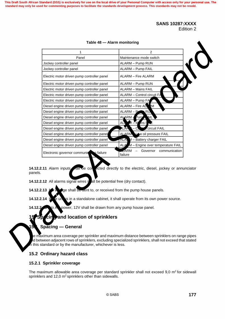
SANS 10287:XXXX Edition 2
177
Table 48 — Alarm monitoring
1 2
Panel Maintenance mode switch
Jockey controller panel ALARM – Pump RUN
Jockey controller panel ALARM – Pump FAIL
Electric motor driven pump controller panel ALARM – Fire ALARM
Electric motor driven pump controller panel ALARM – Pump RUN
Electric motor driven pump controller panel ALARM – Mains FAIL
Electric motor driven pump controller panel ALARM – Control circuit FAIL
Electric motor driven pump controller panel ALARM – Pump FAIL
Diesel engine driven pump controller panel ALARM – Fire ALARM
Diesel engine driven pump controller panel ALARM – Pump RUN
Diesel engine driven pump controller panel ALARM – Pump FAIL
Diesel engine driven pump controller panel ALARM – Mains FAIL
Diesel engine driven pump controller panel ALARM – Control circuit FAIL
Diesel engine driven pump controller panel ALARM – Low oil pressure FAIL
Diesel engine driven pump controller panel ALARM – Battery charger FAIL
Diesel engine driven pump controller panel ALARM – Engine over temperature FAIL
Electronic governor communication failure ALARM – Governor communication failure
14.12.2.11 Alarm inputs shall be connected directly to the electric, diesel, jockey or annunciator panels. 14.12.2.12 All alarms signal wires shall be potential free (dry contact). 14.12.2.13 No voltage shall be sent to, or received from the pump house panels. 14.12.2.14 If the unit is in a standalone cabinet, it shall operate from its own power source. 14.12.2.15 No AC power, 12V shall be drawn from any pump house panel.
15 Spacing and location of sprinklers
15.1 Spacing — General The maximum area coverage per sprinkler and maximum distance between sprinklers on range pipes and between adjacent rows of sprinklers, excluding specialized sprinklers, shall not exceed that stated in this standard or by the manufacturer, whichever is less.
15.2 Ordinary hazard class
15.2.1 Sprinkler coverage The maximum allowable area coverage per standard sprinkler shall not exceed 9,0 m2 for sidewall sprinklers and 12,0 m2 sprinklers other than sidewalls.
© SABS
This Draft South African Standard (DSS) is exclusively for use on the local drive of your Personal Computer with access only for your personal use. The
standard may only be used for commenting purposes to facilitate the standards development process. This standards may not be resold.
Draft S
A Stan
dard

SANS 10287:XXXX Edition 2
178
15.2.2 Sidewall sprinklers Maximum distance between sidewall sprinklers on range pipes and between adjacent rows of sprinklers shall not exceed the following: a) along the walls: Ordinary hazard systems 3,4 m; and b) from end walls: Ordinary hazard systems 1,8 m.
15.2.3 Distance between rows of sidewall sprinklers 15.2.3.1 For rooms not exceeding 3,4 m in width, only one row of sprinklers lengthwise of the room shall be provided. 15.2.3.2 For rooms more than 3,4 m in width but not exceeding 6,8 m, one row of sprinklers at each side lengthwise of the room shall be provided. In the case of rooms exceeding 6,8 m in width, the sprinklers shall be regularly staggered so that sprinklers face midway between the sprinklers on the opposing wall (see figure 37). 15.2.3.3 In rooms exceeding 6,8 m in width, conventional, spray or ceiling type sprinklers centrally positioned under the ceiling shall be provided to supplement the sidewall sprinklers (see figure 37). 15.2.3.4 Sidewall sprinklers are intended for use in rooms with flat, smooth ceilings. 15.2.3.5 There shall be no obstruction at the ceiling within a square extending along the wall 1,0 m on each side of the sprinkler and 1,8 m perpendicular to the wall. 15.2.3.6 Beams on the boundary of this square shall not exceed a depth of 100 mm; beams of a greater depth than 100 mm shall not be closer to a sprinkler than as specified in table 49, otherwise the bays thus formed shall be separately protected. 15.2.3.7 Unless as defined or required by the manufacturer, the deflectors of sidewall sprinklers shall not be more than 150 mm nor less than 100 mm from the ceilings. The centre line of the sprinklers shall be not less than 50 mm or more than 150 mm from the wall face on which it is mounted. 15.2.3.8 Extended coverage sidewall sprinklers are specialized and where installed, the manufacturer’s specifications shall be used.
© SABS
This Draft South African Standard (DSS) is exclusively for use on the local drive of your Personal Computer with access only for your personal use. The
standard may only be used for commenting purposes to facilitate the standards development process. This standards may not be resold.
Draft S
A Stan
dard

SANS 10287:XXXX Edition 2
179
Figure 37 — Sidewall sprinkler room configurations
© SABS
This Draft South African Standard (DSS) is exclusively for use on the local drive of your Personal Computer with access only for your personal use. The
standard may only be used for commenting purposes to facilitate the standards development process. This standards may not be resold.
Draft S
A Stan
dard
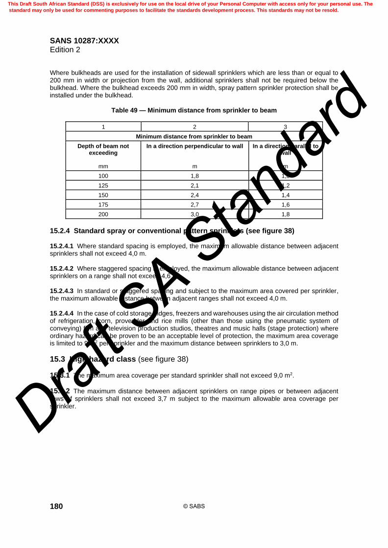
SANS 10287:XXXX Edition 2
180
Where bulkheads are used for the installation of sidewall sprinklers which are less than or equal to 200 mm in width or projection from the wall, additional sprinklers shall not be required below the bulkhead. Where the bulkhead exceeds 200 mm in width, spray pattern sprinkler protection shall be installed under the bulkhead.
Table 49 — Minimum distance from sprinkler to beam
1 2 3
Minimum distance from sprinkler to beam
Depth of beam not exceeding
mm
In a direction perpendicular to wall
m
In a direction parallel to wall
m
100 1,8 1,0
125 2,1 1,2
150 2,4 1,4
175 2,7 1,6
200 3,0 1,8
15.2.4 Standard spray or conventional pattern sprinklers (see figure 38) 15.2.4.1 Where standard spacing is employed, the maximum allowable distance between adjacent sprinklers shall not exceed 4,0 m. 15.2.4.2 Where staggered spacing is employed, the maximum allowable distance between adjacent sprinklers on a range shall not exceed 4,6 m. 15.2.4.3 In standard or staggered spacing and subject to the maximum area covered per sprinkler, the maximum allowable distance between adjacent ranges shall not exceed 4,0 m. 15.2.4.4 In the case of cold storage fridges, freezers and warehouses using the air circulation method of refrigeration, corn, provender and rice mills (other than those using the pneumatic system of conveying) film and television production studios, theatres and music halls (stage protection) where ordinary hazard can be proven to be an acceptable level of protection, the maximum area coverage is limited to 9 m2 per sprinkler and the maximum distance between sprinklers to 3,0 m.
15.3 High hazard class (see figure 38)
15.3.1 The maximum area coverage per standard sprinkler shall not exceed 9,0 m2.
15.3.2 The maximum distance between adjacent sprinklers on range pipes or between adjacent rows of sprinklers shall not exceed 3,7 m subject to the maximum allowable area coverage per sprinkler.
© SABS
This Draft South African Standard (DSS) is exclusively for use on the local drive of your Personal Computer with access only for your personal use. The
standard may only be used for commenting purposes to facilitate the standards development process. This standards may not be resold.
Draft S
A Stan
dard

SANS 10287:XXXX Edition 2
181
Figure 38 — Standard spacing arrangement
15.4 Staggered spacing (see figure 39)
15.4.1 Where sprinklers are required to be staggered, the arrangements shall be uniform.
15.4.2 The distance from the end sprinkler to the wall or partition in each alternate row shall be one-quarter of the design sprinkler spacing down the row and the spacing of the next sprinkler in the same row shall be three-quarters the design spacing.
15.4.3 The maximum area coverage for the respective hazard class as stated in this standard shall not be exceeded.
15.5 Minimum distance between sprinklers
15.5.1 Other than that of intermediate sprinkler protection, sprinklers shall not be spaced closer than 1,8 m for spray pattern sprinklers and 2,0 m for conventional pattern sprinklers except where intervening construction features provide a satisfactory baffle or where special baffles as described in this standard are installed, in order to prevent the first sprinkler operating from wetting adjacent sprinklers.
15.5.2 For extended throw sidewall sprinklers, the adjacent or opposing sprinklers shall be positioned at least 1,0 m past the extremity of the coverage as taken from the manufacturer’s manual.
15.5.3 Baffles shall be not less than 200 mm wide and 150 mm high and preferably of sheet metal or similar incombustible material. They shall be located midway between sprinklers and arranged to baffle the actuating elements. When placed on range pipes, the top of the baffles shall extend above the deflectors by 75 mm to 100 mm.
© SABS
This Draft South African Standard (DSS) is exclusively for use on the local drive of your Personal Computer with access only for your personal use. The
standard may only be used for commenting purposes to facilitate the standards development process. This standards may not be resold.
Draft S
A Stan
dard

SANS 10287:XXXX Edition 2
182
Figure 39 — Staggered spacing arrangement
15.6 Location of sprinklers
15.6.1 Sprinklers shall be located under beams or in bays or a combination of both, provided the locations comply with the requirements specified in this standard.
15.6.2 Where roofs or ceilings are constructed using beams and girders or profile panelling, sprinklers shall be located in bays rather than under beams.
15.6.3 Where the ceiling is profiled the distance from the ceiling shall be measured from the top of the profile. The deflector position relative to the ceiling profiling shall comply with this standard.
15.6.4 The use of any rule in respect of obviating structural obstructions at roof or ceiling level such as beams, columns, girders and trusses in order to avoid bay protection and to space adjacent ranges the maximum distance apart is not an acceptable method of protecting a structure.
15.6.5 In addition to meeting the limitations specified for the maximum area coverage per sprinkler and the maximum distance between sprinklers, sprinklers shall be so located that there will be minimum interference to the discharge pattern by structural members such as beams, columns, girders and trusses, or any other obstructing features.
15.6.6 Sprinklers shall be located at the appropriate distance below ceilings and beams as required in this standard.
© SABS
This Draft South African Standard (DSS) is exclusively for use on the local drive of your Personal Computer with access only for your personal use. The
standard may only be used for commenting purposes to facilitate the standards development process. This standards may not be resold.
Draft S
A Stan
dard

SANS 10287:XXXX Edition 2
183
15.7 Walls and partitions
15.7.1 Except as provided for in this standard, the distance of sprinklers from internal walls or partitions shall not exceed 2,0 m or half the design distance, whichever is the lesser in Ordinary or High Hazard systems.
15.7.2 Where the boundary of the partition is irregular the following equation can be used in order to determine the maximum allowable distance:
M = 0,5 × 22
DS
where M is the distance between a sprinkler and the nearest point of the boundary in metres (m); S is the distance between sprinklers on a range pipe in metres (m); D is the distance between range pipes in metres (m).
15.7.3 The minimum distance a sprinkler may be from a wall, partition, or end or side of fixtures or fittings, (such as lighting that protrudes beneath the finished level of ceilings or roof structures), shall not be less than 150 mm.
15.7.4 In the case of open joist ceilings or where the roof has the rafters exposed, the distance from walls and partitions shall not exceed 1,5 m.
15.7.5 Sprinklers shall not be spaced more than 1,5 m or half the design distance, whichever is the lesser from a) open joist ceilings or where the roof has the rafters exposed, b) open-faced buildings from the open face, c) where the external walls are of or are lined with combustible material, d) where the external walls are combustible material, and e) where the exterior walls are of metal. NOTE The use of combustible wall cladding or lining is not contemplated within sprinkler protected structures.
15.8 Ceilings and roofs
15.8.1 Roof insulation materials shall be classed as non-combustible.
15.8.2 Thermoplastics for roof or ceiling insulation shall not be used.
15.8.2 Where, whether or not being impregnated with retardants the protection is above a structure such as a cold room or freezer where combustible sandwich or composite panel construction is employed, the following is required: a) the protection shall be to High Hazard with a minimum design density of 7,5 mm per minute over
an assumed maximum area of operation of 260 m2.
© SABS
This Draft South African Standard (DSS) is exclusively for use on the local drive of your Personal Computer with access only for your personal use. The
standard may only be used for commenting purposes to facilitate the standards development process. This standards may not be resold.
Draft S
A Stan
dard

SANS 10287:XXXX Edition 2
184
b) A maximum allowable spacing of 3,0 metres between sprinklers on a range and 3,0 metres between adjacent ranges shall not be exceeded.
c) 79 C or 93 C operating temperature, fast response sprinklers shall be used.
15.8.2 Sprinklers shall be located between 75 mm and 150 mm below ceilings and roofs. Where this is not possible, the area involved shall be as small as possible and the sprinklers installed at lower levels shall have their deflectors not more than a) 300 mm below the underside of combustible ceilings and roofs, or b) 450 mm below the underside of: 1) ceilings of incombustible construction which are in no part less than 75 mm thick, or 2) ceilings of incombustible construction less than 75 mm thick but which are affixed to the
underside of a fireproof floor, or 3) roofs entirely of incombustible construction, (excluding asbestos cement sheeting, wired glass
and other similar frangible materials which are to be treated as combustible). The minimum allowable distance of 75 mm shall be adhered to for sprinklers installed in the upright position in order to facilitate their removal.
15.8.3 A hollow block or concrete roof may be covered externally with a weatherproofing material, with or without a layer of heat insulating material between it and the roof, provided there is no intervening air space.
15.8.4 With open joist ceilings the deflectors shall be not more than 150 mm below the underside of the joists.
15.8.5 With exposed common rafters in roofs the measurements shall be taken from the underside of the rafters.
15.8.6 With arched ceilings the measurements are to be taken from the crown of the arch.
15.8.7 With skylights with a volume greater than 1,0 m3 measured above the normal ceiling or roof level shall be sprinkler protected unless the distance from the normal ceiling or roof level and the skylight does not exceed 300 mm, or there is a tightly fitting frame and glass fitted level with the roof or ceiling.
15.8.8 Deflectors of sprinklers shall be parallel to the slope of the ceiling, roof or incline of stairs.
15.8.9 Where sloping ceilings or roofs are concerned, the spacing measurements are to be taken horizontally.
15.8.10 Where the roofs incline changes more than 45, the angle changes shall be treated as a wall or other obstruction, and the sprinkler position will be determined from this point.
15.8.11 Where a roof or ceiling rises or drops more than 450 mm the change in elevation shall be treated as a wall or other obstruction whereby the sprinkler position will be determined from this point.
15.8.12 Where the slope is greater than 1 in 3, a line of sprinklers shall be fixed at the apex or not more than 750 mm radially from it.
© SABS
This Draft South African Standard (DSS) is exclusively for use on the local drive of your Personal Computer with access only for your personal use. The
standard may only be used for commenting purposes to facilitate the standards development process. This standards may not be resold.
Draft S
A Stan
dard
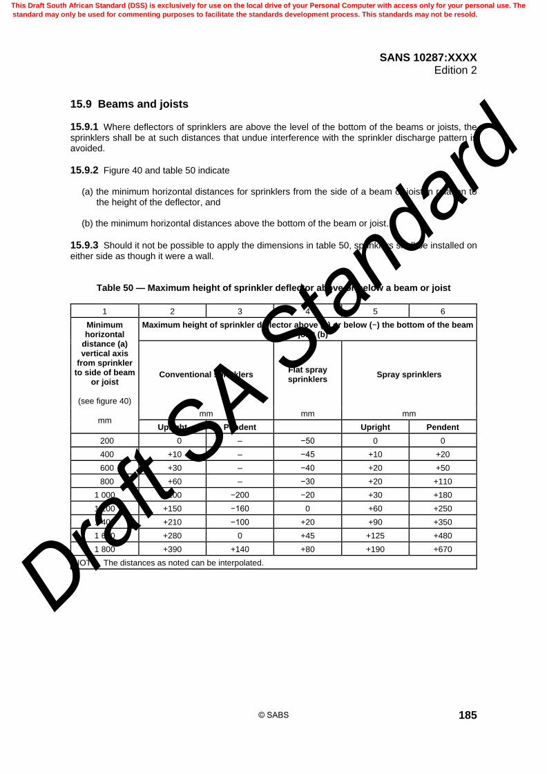
SANS 10287:XXXX Edition 2
185
15.9 Beams and joists
15.9.1 Where deflectors of sprinklers are above the level of the bottom of the beams or joists, the sprinklers shall be at such distances that undue interference with the sprinkler discharge pattern is avoided.
15.9.2 Figure 40 and table 50 indicate
(a) the minimum horizontal distances for sprinklers from the side of a beam or joist in relation to the height of the deflector, and
(b) the minimum horizontal distances above the bottom of the beam or joist.
15.9.3 Should it not be possible to apply the dimensions in table 50, sprinklers shall be installed on either side as though it were a wall.
Table 50 — Maximum height of sprinkler deflector above or below a beam or joist
1 2 3 4 5 6
Minimum horizontal
distance (a) vertical axis
from sprinkler to side of beam
or joist
(see figure 40)
Maximum height of sprinkler deflector above (+) or below (−) the bottom of the beam or joist (b)
Conventional sprinklers Flat spray sprinklers
Spray sprinklers
mm mm mm mm
Upright Pendent Upright Pendent
200 0 – −50 0 0
400 +10 – −45 +10 +20
600 +30 – −40 +20 +50
800 +60 – −30 +20 +110
1 000 +100 −200 −20 +30 +180
1 200 +150 −160 0 +60 +250
1 400 +210 −100 +20 +90 +350
1 600 +280 0 +45 +125 +480
1 800 +390 +140 +80 +190 +670
NOTE The distances as noted can be interpolated.
© SABS
This Draft South African Standard (DSS) is exclusively for use on the local drive of your Personal Computer with access only for your personal use. The
standard may only be used for commenting purposes to facilitate the standards development process. This standards may not be resold.
Draft S
A Stan
dard

SANS 10287:XXXX Edition 2
186
Figure 40 — Distance of a sprinkler deflector from beams
15.10 Coffer, waffle or shofco slab constructions
15.10.1 Providing the sprinkler deflector is within the maximum allowable distance from the soffit of the coffer, the deflector shall be within the coffer itself and shall be positioned on the underside of the rib at the intersect point between the coffers or shofco construction.
15.10.2 The deflector shall be below the level of the rib and range pipes shall be positioned beneath these. In all cases pendent or upright style spray pattern sprinklers shall be used.
15.10.3 Where narrow bays are formed by coffer construction and the beams are spaced at not more than 1,5 m centres, the sprinkler ranges may be positioned beneath the beams and every alternate row of sprinklers shall be positioned within the coffer with the sprinkler deflector within 75 mm to 150 mm of the soffit.
15.10.4 The sprinkler shall be installed at a distance of no greater than 1,0 m from any wall running parallel to the beams and 1,5 m from the walls perpendicular to the beams.
15.10.5 The distance between sprinklers on a range (S) and the distance between adjacent ranges (D) shall not exceed that allowable under the hazard class.
15.10.6 Where the depth of the beam (or joist) exceeds 300 mm (combustible ceilings) or 450 mm, (incombustible ceilings), and it is impracticable to position sprinklers at the required distance from the side of the beam, the beam shall be treated as a wall so far as the sprinklers in the adjoining bay are concerned.
15.10.7 Where the depth of beams (or joists) are such that the dimensions specified in table 50 cannot be complied with and the beams (or joists) are spaced closer than 1,8 m, measured from centre to centre of beam, special consideration may be applied if the parameters do not exceed those of the manufacturer.
15.10.8 In such cases, as mentioned in 15.10.7, sprinklers shall be stagger-spaced as shown in figure 41. Where beams of these depths are spaced closer than 1,2 m, it is strongly recommended that they be under-drawn with substantial incombustible material.
© SABS
This Draft South African Standard (DSS) is exclusively for use on the local drive of your Personal Computer with access only for your personal use. The
standard may only be used for commenting purposes to facilitate the standards development process. This standards may not be resold.
Draft S
A Stan
dard

SANS 10287:XXXX Edition 2
187
Figure 41 — Positioning of sprinkler beneath a typical coffer or beam construction
15.10.9 Columns In general, sprinklers shall be spaced well clear of columns. Where it is unavoidable that individual sprinklers fall within 600 mm of any column, the obstruction to the distribution of water from the sprinkler shall be minimised by placing a sprinkler within 2,0 m of the opposite face of the column.
15.10.10 Girders Sprinklers shall be at least 1,2 m from girders except that where the top flange of girders does not exceed 200 mm nominal in width, sprinklers may be located directly over the girder, provided the sprinkler deflectors are not less than 150 mm above the top of the girder.
15.10.11 Roof trusses Sprinklers shall be installed in accordance with one of the following: a) 150 mm directly above the truss where the flange of the truss is no more than 200 mm wide; b) not less than 300 mm laterally from truss members where the flange of the truss member is not
more than 100 mm in width; or c) where the flange of the truss members exceed 100 mm wide, the sprinklers shall be at least
600 mm laterally therefrom. Where sprinkler ranges are located parallel to the truss members, the distance of the sprinkler deflectors therefrom shall be in accordance with table 50.
© SABS
This Draft South African Standard (DSS) is exclusively for use on the local drive of your Personal Computer with access only for your personal use. The
standard may only be used for commenting purposes to facilitate the standards development process. This standards may not be resold.
Draft S
A Stan
dard

SANS 10287:XXXX Edition 2
188
15.10.12 Clear space below sprinklers In limited head space areas, a clear space of at least 500 mm shall always be maintained below the level of the sprinkler deflectors throughout the room for Ordinary Hazard. For high piled combustible stock, increased clearance of 1,0 m or more shall be provided. Roof trusses shall at all times be accessible to water discharged from the sprinklers. Where sloping ceilings or roofs are concerned, the storage of goods may follow the slope thereof, subject to compliance with the requirements in this standard.
16 Locations or conditions involving special consideration (supplementary protection)
16.1 Concealed spaces
16.1.1 Non-combustible concealed spaces having an exposed combustible insulation where the heat content does not exceed 11,500 kJ per m2 shall not require sprinkler protection.
16.1.2 A plenum is defined as an unoccupied space, typically a ceiling void, throughout which air is circulated or moved at above or below atmospheric pressure, for heating, ventilation or air conditioning purposes.
16.1.3 Concealed spaces of non-combustible and limited combustible construction with minimal combustible loading having no access shall not require sprinkler protection, i.e. less than 11,500 kJ per m2 combustible loading.
16.1.4 Concealed spaces of non-combustible and limited combustible construction with limited access and not permitting occupancy or storage of combustibles shall not require sprinkler protection.
16.1.5 Concealed spaces over isolated small rooms not exceeding 5,0 m2 in area shall not require sprinkler protection.
16.1.6 Concealed spaces where rigid materials are used and the exposed surfaces have a flame spread index of 25 or less, and the materials have been demonstrated not to propagate fire when tested in accordance with NFPA 255, extended for an additional 20 min in the form in which they are installed, shall not require sprinkler protection.
16.1.7 Sprinklers installed in the upright position shall be used for the protection of concealed spaces where practicable.
16.1.8 Sprinklers installed upright are usually more effective than pendent sprinklers where the height of the concealed space is limited.
16.1.9 Sprinklers used to protect concealed spaces shall be rated as fast response thermal sensitivity.
16.1.10 Sprinklers protecting ceiling ventilation intake plenums shall be rated as standard response thermal sensitivity.
© SABS
This Draft South African Standard (DSS) is exclusively for use on the local drive of your Personal Computer with access only for your personal use. The
standard may only be used for commenting purposes to facilitate the standards development process. This standards may not be resold.
Draft S
A Stan
dard

SANS 10287:XXXX Edition 2
189
16.1.11 If there is any communication between the ceiling level sprinklers and the void protection or the void is being used as a return air plenum, the sprinklers protecting a concealed space shall be fed from separate pipework or from the pipework serving an adjoining room.
16.1.12 Where combustible materials are used in construction of concealed spaces, or where there is open communication between the protected room or area and the concealed space, for example, sprinkler protected ventilation plenums, simultaneous operation of sprinklers in the concealed space and the naturally accompanying or associated room shall be assumed when determining pipe sizes and pressure and flow characteristics of the installation.
16.1.13 Where non-combustible materials are used in the construction of concealed spaces and there is no communication between the protected space and the room, simultaneous operation of the void and protection beneath the void ceiling need not be assumed.
16.2 Roof spaces
16.2.1 The spaces between ceilings and roofs including those at the apex and sides of buildings exceeding 800 mm in depth in any portion measured between the underside of the roof and the top of the ceiling or soffit of concrete construction shall be sprinkler protected. In the case of spaces less than 800 mm in depth where combustible construction is involved, a suitable cavity barrier shall be installed.
16.2.2 Such cavity barrier shall be provided for vertical division and at approximately 15,0 m intervals for horizontal division.
16.3 Floor spaces — Ceiling voids
16.3.1 Where concealed spaces between floors and ceilings below exceed 800 mm in depth measured from the top of the ceiling board to the underside of the floor above or soffit if of concrete construction contain any combustible materials, including PVC conduits, they shall be fitted with sprinklers.
16.3.2 In the case of spaces less than 800 mm in depth where combustible construction is involved, suitable cavity barriers shall be installed. Such cavity barriers shall provide compartmented areas not exceeding 225 m2.
16.3.3 Where extensive concealed spaces between floors and ceilings are of non-combustible material, the ceiling tiles and grid system shall have a minimum rating of 30 min and shall resist the passage of flames, heat and smoke for this period. Where it is impractical to install protection a suitable smoke detection system shall be installed. Smoke detection or ventilation is not a substitution for sprinkler protection. Protection at roof or ceiling level may be omitted above cloud ceilings where the open area between does not exceed 20 % of the total area under consideration. The maximum allowable width between ceiling sections shall not exceed 200 mm.
16.4 Spaces under floors Sprinklers shall be installed in all spaces below combustible floors, except where: a) the space is not accessible for storage purposes or entrance of unauthorized persons, and is
protected against accumulation of debris; b) the space contains no equipment such as steam pipes, electric wiring (except cables in metal
conduit or mineral insulated copper-sheathed cables, suitably earthed) shafting or conveyors;
© SABS
This Draft South African Standard (DSS) is exclusively for use on the local drive of your Personal Computer with access only for your personal use. The
standard may only be used for commenting purposes to facilitate the standards development process. This standards may not be resold.
Draft S
A Stan
dard

SANS 10287:XXXX Edition 2
190
c) the floor over the space is tight in respect of services and access; and d) No flammable liquids are stored on the floor above.
16.5 Ceiling void ventilation systems or air conditioning plenums
16.5.1 Where ceiling voids are used as plenums for ventilation or air conditioning systems the following shall apply: a) The ceiling void plenum shall be protected by a suitable automatic fire detection system. Operation
of the ceiling void fire detection shall automatically shut down the ventilation system; b) The ceiling void plenum shall be inspected at least every six months for the build-up of dust or
debris and cleaned as necessary. c) Where the plenum construction is not combustible and the plenum contains combustible material
the plenum void need not be fitted with sprinklers.
16.5.2 Where the plenum construction is combustible or the plenum contains combustible materials such as PVC conduit or wiring, the plenum void shall be sprinkler protected and the assumed maximum area of operation required for the risk as stated in this standard beneath the plenum shall be increased by four sprinklers from within the plenum void area.
16.6 Roof spaces that vary in depth Where the roof space changes in depth and the deeper section requires sprinkler protection the roof space shall be either a) sprinkler protected throughout, or b) sprinkler protected within the section greater than 800 mm in depth and compartmentalized with
cavity barriers in those areas less than 800 mm in depth.
16.7 Ceiling voids protected with CPVC pipe
16.7.1 CPVC pipe shall not be used for the protection of intermediate floor spaces or ceiling voids only.
16.7.2 CPVC pipe may be used within a ceiling void where the pipe is supplying sprinklers protecting the area below the void.
16.7.3 Plastic pipe shall not be used where the floor space or void is used as a ventilation plenum.
16.7.4 Where CPVC pipe is concealed, it shall have a minimum protection of a) one layer of 10 mm gypsum wallboard or equivalent, b) suspended non-combustible ceiling weighing not less than 1,7 kg per m2, or c) alternative protection having not less than 30 min fire rating.
© SABS
This Draft South African Standard (DSS) is exclusively for use on the local drive of your Personal Computer with access only for your personal use. The
standard may only be used for commenting purposes to facilitate the standards development process. This standards may not be resold.
Draft S
A Stan
dard

SANS 10287:XXXX Edition 2
191
16.8 Suspended ceilings under drawn ceilings
16.8.1 The use of any material below the sprinklers, (as for example in connection with diffused lighting), is not allowed unless that material is shown through approved fire testing not to impair sprinkler protection.
16.8.2 Where sprinklers are fitted below suspended ceilings, the material shall be of a type which has been shown through approved testing not to be subject to partial collapse under fire conditions.
16.8.3 Spray pattern sprinklers fitted with escutcheon plates shall be used for the protection of the underside of suspended ceilings.
16.9 Suspended open ceilings
16.9.1 Suspended open ceilings are ceilings with a regular open cell construction recurring throughout their design. They are usually fitted for aesthetic purposes, but when positioned below a sprinkler system shall not prevent its effective operation.
16.9.2 Suspended open ceilings may be permitted beneath ordinary hazard sprinkler systems not involving storage areas. The suspended open ceilings and sprinkler arrangement shall comply with the following requirements: a) suspended open ceilings shall preferably be of non-combustible construction and shall not be liable
to collapse before operation of sprinklers; b) the ceiling shall be suspended on non-combustible supports, and the materials shall not cause
dripping of molten particles in fire conditions; c) the structural integrity of the suspended open ceilings and any other equipment such as light fittings
within the volume above the suspended open ceilings, shall not affect the operation of the sprinkler system;
d) the total plan open area of the suspended open ceiling shall not be less than 70 % of the ceiling
plan area; e) services installed in suspended open ceilings such as light fittings, shall not reduce the open plan
area of the ceiling below 60 % of the total ceiling plan area; f) supplementary sprinklers shall be provided to discharge below light fittings or similar obstructions
exceeding 800 mm in width; g) the minimum dimension of the openings shall not be less than 25 mm or the vertical thickness of
the suspended ceilings, whichever is the greater; h) the sprinkler spacing above suspended open ceilings shall not exceed 3,0 m with an area of
coverage not exceeding 9 m2; i) the vertical separation between any sprinkler deflector and the top of the suspended ceiling shall
not be less than 800 mm for sprinklers other than flat spray sprinklers and not less than 300 mm if flat spray sprinklers are used; and
j) wherever obstructions within the ceiling void are likely to cause significant interference of the water
discharge they shall be treated as walls for the purpose of sprinkler spacing.
© SABS
This Draft South African Standard (DSS) is exclusively for use on the local drive of your Personal Computer with access only for your personal use. The
standard may only be used for commenting purposes to facilitate the standards development process. This standards may not be resold.
Draft S
A Stan
dard

SANS 10287:XXXX Edition 2
192
16.10 Concealed wall cavities
16.10.1 Concealed spaces or cavities between walls which have combustible linings that exceed 100 mm in width and those between roofs and combustible linings which exceed 100 mm in depth shall be fitted with sprinklers.
16.10.2 Electric cables are permitted provided the wiring is either in a screwed steel conduit or in mineral-insulated metal-sheathed cable.
16.11 Composite panels and roof or ceiling insulation materials
16.11.1 A fire involving combustible insulation will result in this spreading in an uncontrolled manner above the line of sprinklers, therefore, tests for determining the fire classification shall comply with relevant standards.
16.11.2 It is the responsibility of the building designer to ensure that the insulation materials used will not contribute to a fire.
16.11.3 A roof or ceiling insulation that is classed as non-combustible in accordance with relevant testing standards shall be used within sprinkler protected premises.
16.11.4 Where the use is unavoidable or existing such as for fridge, freezers and cold rooms and the roof insulation or composite panels which have either a positive flame spread index or are hydrocarbon based (whether or not impregnated or treated with fire retardants), the following requirements shall be applied: a) subject to the storage requirements design densities of discharge, the protection within and above
composite panel structures shall have a minimum design density of discharge of not less than 7,5 mm per minute over an assumed maximum area of operation of 260 m2;
b) the maximum allowable spacing for sprinkler protection within and above a composite panel
structure or a structure that has a roof or ceiling insulation installed that is classed as combustible shall not exceed 3,0 m between adjacent sprinklers on a range and 3,0 m between adjacent ranges and not more than 0,6 m from the side walls;
c) the protection, inclusive of ESFR sprinklers if used, within such a structure shall have a line of
sprinklers not more than 0,6 m from the side walls; d) the ceiling sprinkler protection shall not exceed 3,0 m between adjacent sprinklers on a range and
3,0 m between adjacent ranges; d) where walls are of combustible composite panels but not the roof or ceiling, sprinklers at roof or
ceiling level shall be spaced no more than 0,6 m from each wall; e) for Ordinary Hazard risks and occupancies, conventional pattern, fast response sprinklers with an
operating temperature of 68 C and Response Time Index of less than 50 shall be used for rooms
maintained above freezing which is deemed to be 5 C or more. f) for High Hazard risks and occupancies, conventional pattern, fast response sprinklers with an
operating temperature of 93 C and Response Time Index of less than 50 shall be used for rooms
maintained above freezing which is deemed to be 5 C or more.
16.11.5 Cold rooms, freezers and fridges irrespective of construction materials or constructed of composite panels using expanded plastics, hydrocarbons or similar products such as polystyrene whether or not impregnated with retardants and irrespective of size shall be fully sprinkler protected.
© SABS
This Draft South African Standard (DSS) is exclusively for use on the local drive of your Personal Computer with access only for your personal use. The
standard may only be used for commenting purposes to facilitate the standards development process. This standards may not be resold.
Draft S
A Stan
dard
SANS 10287:XXXX Edition 2
193
16.12 Shopping malls and building atria
16.12.1 The protection of shopping malls and building atria shall not be omitted if the shopping malls and atria are not as described in 16.12.2, as the operation of these critical sprinklers under a fire condition helps to safeguard life safety and structural stability.
16.12.2 Sprinklers may be omitted from shopping malls and atria where a) the shopping mall is of lofty construction, i.e. above 15,0 m, b) the shopping mall is of non-combustible construction, c) the amount of combustible material, (floor level and overall construction), is negligible, d) those portions of the shopping mall or atrium under consideration are not used for seating, display
or retail purposes, e) there is a rated fireproof barrier between each adjacent shop in the shopping mall, f) the void areas are fully sprinkler protected if these exceed 800 mm in depth, g) the shop frontage is sprinkler protected on the shopping mall side, and h) there is a fireproof barrier between the shopping mall and shops or atrium and the ceiling void
above the shops regardless of whether or not such a void is or is not sprinkler protected.
16.12.3 Sprinklers may not be omitted from shop fronts
16.13 Ventilation in sprinkler-protected premises
16.13.1 Sprinkler systems shall be designed to ensure that the sprinkler heads are not positioned beneath the throat of a ventilator or an extract area.
16.13.2 In life safety structures where the opening of vents will facilitate in the evacuation of occupants, a fast opening system such as that linked to a fire detection system should be considered.
16.13.3 Manually operated ventilators shall be used within storage premises where the growth of a fire may be rapid and especially where fast response or specialized sprinklers are used.
16.13.4 Where there are no high stacks of goods or products that represent a high fire load ventilators may open under a fire condition using fusible links, the operating temperature of the link shall be set to above the operating temperature of the roof or ceiling level sprinkler protection.
16.14 Machinery pits where waste may collect and the underside
of production lines Such machinery pits and production lines shall be fully sprinkler protected.
16.15 Hoists, lift shafts and enclosed chutes through floors
16.15.1 All hoists, lift shafts and chutes inside or in communication with the sprinkler protected buildings other than as specified in this standard shall be protected by sprinklers.
© SABS
This Draft South African Standard (DSS) is exclusively for use on the local drive of your Personal Computer with access only for your personal use. The
standard may only be used for commenting purposes to facilitate the standards development process. This standards may not be resold.
Draft S
A Stan
dard

SANS 10287:XXXX Edition 2
194
16.15.2 Where sprinklers are installed at the head of lift shafts, these shall be protected by metal guards which are approved.
16.16 Elevators, rope or strap races, gearing boxes and dust receivers
16.16.1 A sprinkler shall be fitted in the box at the top of every elevator, (other than those of the pneumatic type or which comprise a slow moving endless chain fitted with rings, loops or forks, capable of functioning only when the elevator is full). The sprinkler in each case shall be so placed as to command the head and both legs or shafts of the elevator.
16.16.2 Sprinklers shall be fitted internally in all rope or strap races, gearing boxes and in all enclosed belt or shaft machine drives.
16.16.3 Sprinklers shall be fitted in dust cyclones, collection chambers and boxes where a) housed within the protected building, b) erected outside and directly above the protected building unless the roof is of incombustible
construction, and c) external to but connected with and closely adjacent (within 10,0 m) to the protected buildings.
16.16.4 Where dust cyclones, collection chambers and boxes are erected above non-combustible roofs or where they are situated remote from the protected building (more than 10,0 m) at least one sprinkler shall be fitted inside the trunking where it leaves the protected building.
16.17 Corn, rice, provender and oil mills
16.17.1 Sprinklers shall be fitted not more than 3,0 m apart inside all dust trunks which are more than 30o from the vertical and constructed of combustible materials.
16.17.2 A sprinkler shall be fitted at the head of every dust trunk.
16.17.3 When centrifuges or similar machines are placed one above another in tiers and are less than 1,0 m from each other, sprinklers shall be fitted in the spaces as shown in figure 42.
© SABS
This Draft South African Standard (DSS) is exclusively for use on the local drive of your Personal Computer with access only for your personal use. The
standard may only be used for commenting purposes to facilitate the standards development process. This standards may not be resold.
Draft S
A Stan
dard

SANS 10287:XXXX Edition 2
195
Figure 42 — Suitable location for sprinklers protecting centrifuges
or cyclones spaced less than 1,0 m apart
16.18 Bins and silos
16.18.1 All bins and silos of combustible construction having a plan area in excess of 9 m2 for the storage of flour, bran, or other similar material which has undergone any process of reduction, (in such premises as flour mills, granaries, oil mills or distilleries), or for the storage of sawdust, wood flour, pulverized coal and similar easily ignitable materials which can be extinguished by water, shall be internally protected by sprinklers on the basis of one sprinkler per 9 m2 of the bin or silo area.
16.18.2 If the bin or silo contains material which will swell if wet and thereby incur the risk of bursting, exemption from the requirement in 16.18.1 may be applied.
16.19 Escalators and lift shafts
16.19.1 Providing the area beneath an escalator or stairwell contains no combustible materials or is used for concessions, protection will not be required beneath these structures but the number of sprinklers around the peripheral opening formed by the escalator or stairwell shall be increased.
16.19.2 Sprinklers shall not be more than 1,8 m apart and shall not exceed 0,5 m from the face of the opening.
16.19.3 For the purpose of hydraulic calculation, only the sprinklers on the longer side of the opening need be considered.
16.20 Canopies
16.20.1 Sprinklers shall be installed under all canopies where goods are offloaded, stored or handled and which communicate with the sprinkler-protected building. The design density of discharge for the protection of a canopy shall not be less than that within the main facility.
16.20.2 Canopies which are of incombustible construction and do not extend more than 2,3 m from the wall of the building need not be fully protected provided that cut-off sprinklers are fitted under the canopy over each of the openings into the sprinkler-protected building.
16.20.3 Where such openings do not exceed 2,5 m in width, one sprinkler positioned centrally over each opening will suffice. Where openings exceed 2,5 m in width, the sprinklers over the openings shall be spaced not more than 2,5 m apart and not more than 1,25 m from the sides of the opening.
16.20.4 Where canopies or loading ways for warehousing are less than 1,2 m wide or are over a public street designated as such by a municipality, protection may be waived.
16.20.5 The maximum distance from the edge of a canopy to the terminal sprinklers shall not exceed 1,5 m.
16.21 Exterior docks and platforms Sprinklers shall be installed under exterior docks and loading platforms of combustible construction unless such space is closed off against the accumulation of debris.
© SABS
This Draft South African Standard (DSS) is exclusively for use on the local drive of your Personal Computer with access only for your personal use. The
standard may only be used for commenting purposes to facilitate the standards development process. This standards may not be resold.
Draft S
A Stan
dard
SANS 10287:XXXX Edition 2
196
16.22 Enclosed paint lines, drying ovens and drying enclosures
16.22.1 Sprinkler protection shall be provided inside the above structures. Sidewall sprinklers may be used for this purpose.
16.22.2 Obstructions below sprinklers likely to delay the operation thereof and impair effective water distribution require additional sprinklers beneath them.
16.22.3 Cellophane bags with a thickness of 0,076 mm or less or thin paper bags shall be used to protect sprinklers for spray areas and mixing rooms and in areas where over spray or residue may settle on the sprinklers.
16.22.4 Coverings shall be replaced periodically so that heavy deposits of residue do not accumulate.
16.22.5 Sprinklers that have been painted or coated shall be replaced in accordance with the requirements of this standard.
16.23 Internal mezzanine floors, overhead platforms, heating panels, galleries, walkways, stagings, stairs, stairways, conveyors and chutes Sprinklers are required under these structures if they exceed 800 mm in width regardless of whether they are open grid or of solid construction unless there is at least 150 mm clearance from adjacent walls or partitions and 500 mm clearance below the sprinkler deflector to top of structure when the width without protection may be 1,0 m.
16.24 Ducts Sprinklers are required under rectangular ducts exceeding 800 mm in width and under circular ducts exceeding 1,0 m in diameter, unless there is at least 150 mm clearance from adjacent walls and 500 mm clearance below the sprinkler deflector to top of the duct, when the width without protection may be 1,0 m and 1,2 m respectively.
16.25 Cooking hoods and extract equipment
16.25.1 Cooking areas and surfaces including deep fat fryers shall be protected with nozzles specifically approved for this application. A 6,4 mm orifice or smaller stainless steel wide-angle (120o or larger) full cone discharge water spray nozzles which are approved and listed are deemed to be suitable.
16.25.2 Where the supply has to be taken from a sprinkler installation protecting the remainder of the building, a subsidiary stop valve can be provided to isolate the sprinklers in the event of operation.
16.25.3 Where deep fat frying occurs, if nozzles specifically approved for this purpose are not used,
an automatic foam, dry powder or gas extinguishing system shall be installed.
16.25.4 Water from a sprinkler will initially excite a fat fire before the suppression process commences, occupants of a sprinkler protected kitchen shall leave immediately if a fire occurs.
16.25.5 Sprinkler protection shall be installed within all cooking equipment ventilation systems.
16.25.6 Extraction canopies where these are designed to extract grease laden vapours or heat through a ventilation system shall be fully sprinkler protected, inclusive of exhaust ducts and exhaust
© SABS
This Draft South African Standard (DSS) is exclusively for use on the local drive of your Personal Computer with access only for your personal use. The
standard may only be used for commenting purposes to facilitate the standards development process. This standards may not be resold.
Draft S
A Stan
dard

SANS 10287:XXXX Edition 2
197
plenum chambers, using 93 or 141 °C operating temperature spray pattern type nozzles as appropriate unless alternative protection is installed.
16.25.7 The operation of the fire protection measures taken to protect extract canopies shall automatically shut off any source of fuel and heat.
16.26 Work tables Additional sprinkler protection shall be required beneath work tables over 800 mm in width where the undersides are used for housing of motive power or under which combustible process waste or storage may accumulate.
16.27 Hoods over paper-making machines
16.27.1 The underside of hoods or shields over the dry ends of paper-making machines shall be sprinkler protected. Sidewall sprinklers may be used for this purpose.
16.27.2 Subsidiary stop valves to control these sprinklers may be used.
16.28 Film and television production studios Overhead platforms or walkways including those for lighting or other equipment, whether slatted or not, together with stairs thereto, shall be fitted with sprinklers on the underside if they exceed 800 mm in width. This does not apply to temporary platforms in connection with sets.
16.29 Theatres and music halls
16.29.1 Protection on the stage side of the proscenium wall 16.29.1.1 In addition to the normal sprinkler protection at the roof, sprinklers shall be placed under the grid iron, under the flies, under the stage and in every portion of the stage side of the proscenium wall and in any buildings communicating therewith otherwise than by fireproof doors. 16.29.1.2 Where a fireproof curtain is fitted, it shall be provided with a line of open drenchers spaced at no more than 2,0 m intervals on the apron side of the curtain. The control valve shall be of the quick-opening type and shall be fitted in an easily accessible position at least 10,0 m away from the line of drenchers. 16.29.1.3 The water supply to these open sprinklers or drenchers may be taken from the upstream side of any automatic sprinkler installation valve and shall be capable of catering for the combined operation of the drenchers and the sprinkler system.
16.29.2 Protection on the auditorium side of the proscenium wall 16.29.2.1 Sprinklers shall be placed in the dressing rooms, scenery, storerooms, refreshment bars, cellars, anteroom, in the boxes, under the dress circle, upper circle and under and in the gallery, also directly over the pit and under the ceiling and in the spaces between the ceiling of the auditorium and the roof, whether that space is used for the storage of stage props or not. 16.29.2.2 Where movable scenery is in use (for example under fly gallery floors) and there are projecting sprinklers, particular care shall be taken to ensure that the scenery can be moved safely and that the sprinklers are protected from damage.
16.29.2.3 Sprinklers shall be sited with particular care where personnel might work in close proximity, for example, under the grid, to reduce the risk of impact and injury.
© SABS
This Draft South African Standard (DSS) is exclusively for use on the local drive of your Personal Computer with access only for your personal use. The
standard may only be used for commenting purposes to facilitate the standards development process. This standards may not be resold.
Draft S
A Stan
dard

SANS 10287:XXXX Edition 2
198
16.29.2.4 Stage floors are subject to frequent modification with some parts being removed and others replaced. This is to be taken into account when sprinkler pipework is fitted under the stage. 16.29.2.5 Where hydraulic lifts, etc. are used, special protection should be considered as standard sprinkler protection may not be suitable.
16.30 Computer areas and archive rooms
16.30.1 Sprinkler protection to computer areas or archives is accepted common practice. Circuits within the computer are generally resin-coated with storage media being hermetically sealed. These usually dry quickly after a fire.
16.30.2 However, where a computer is not only a necessity to the operation of a company, but also very costly to replace, two forms of protection shall be installed, i.e. a sprinkler installation and an automatic gas flooding system which is approved.
16.30.3 Sprinklers protecting computer areas shall, where practicable, comprise a separate installation fed directly from the trunk main through a set of main installation control valves. Fast response sprinklers with a response time index of less than 50 shall be used.
16.30.4 However, where the supply has to be taken from a sprinkler installation protecting the remainder of the building, a subsidiary stop valve shall be provided to control the sprinklers in the computer area. The valve shall be either a) electrically monitored at a continuously manned position at which any partial closing of the valve
shall be signalled by a visible and audible alarm, or b) of the interlocking key type.
16.30.5 A local indication of sprinkler operation in the computer area may be given by either a subsidiary alarm valve with hydraulic alarm or a water flow switch which is approved.
16.30.6 A special visual check of sprinkler heads and pipework shall be carried out prior to commissioning.
16.30.7 The system pipework shall be pressurized to 250 kPa with air for 24 h and then retested with water to 1500 kPa. Any leaks revealed by the air pressure test shall be rectified before charging the system with water.
16.30.8 Facilities shall be provided for drainage of the protected area.
16.30.9 Notwithstanding that voids less than 800 mm deep may be left unprotected, there shall be sprinkler protection in such floor and ceiling voids forming cable ways wherever practicable, unless they are protected by an automatic gas extinguishing system which is approved.
17 Early suppression fast response (ESFR) sprinklers
17.1 Preliminary arrangements
17.1.1 The information provided at the preliminary or estimating stage shall include an assessment to establish ability to comply with relevant requirements in this standard.
17.1.2 The assessment shall include a review of the intended actions to comply with all requirements specified in this standard.
© SABS
This Draft South African Standard (DSS) is exclusively for use on the local drive of your Personal Computer with access only for your personal use. The
standard may only be used for commenting purposes to facilitate the standards development process. This standards may not be resold.
Draft S
A Stan
dard

SANS 10287:XXXX Edition 2
199
17.1.3 Any known non-compliance with any other requirements shall be declared.
17.2 Management systems
17.2.1 ESFR sprinkler protection shall only be used in buildings where the property, storage systems and contents are controlled by appropriate management systems.
17.2.2 The management system documentation shall include procedures throughout consisting of at least the following: a) risk assessment controls for incoming goods; b) routine checking and inspection procedures; c) sprinkler system maintenance contract with a sprinkler installer; d) maintenance of an outline specification for the building and fire protection with a record of any
changes which may influence the performance of the sprinkler systems; e) bi-annual review of storage methods; f) bi-annual review of the hazard; g) bi-annual review of compliance with ESFR installation requirements; and h) dealing with non-compliance.
17.2.3 A bi-annual review of the hazard shall include checking that the aisles and flues in the storage comply with the relevant requirements.
17.2.4 The procedures in 17.2.2 shall encompass actions to be taken where non-compliance occurs and shall include informing a relevant authority.
17.3 Occupancies and fire hazards
17.3.1 ESFR sprinklers may be used to protect storage in accordance with tables 8 and 52 to 69.
17.3.2 ESFR sprinklers may be used to protect ordinary hazard and high hazard process areas adjacent to the ESFR protected storage areas.
17.3.3 ESFR sprinklers shall not be used to protect areas where one of the following may be present: a) materials on which fires cannot readily be controlled by sprinklers, (example, acrylic fibre yarn); b) commodities or storage configurations which may give rise to unusual fire characteristics, (for
example, lightweight paper, such as rolls of tissue); c) open top containers, (example, plastic storage boxes such as tote boxes with solid bottoms); d) commodities which have not been assessed or tested for protection by ESFR sprinklers; e) automatic smoke venting; or f) combustible roof insulation.
© SABS
This Draft South African Standard (DSS) is exclusively for use on the local drive of your Personal Computer with access only for your personal use. The
standard may only be used for commenting purposes to facilitate the standards development process. This standards may not be resold.
Draft S
A Stan
dard

SANS 10287:XXXX Edition 2
200
17.3.4 ESFR sprinkler protection may be used in conjunction with manually operated smoke ventilation systems, suitable only for smoke ventilation purposes, operated by the fire brigade.
17.4 Automatic smoke venting ESFR sprinkler protection may be used in conjunction with manually operated smoke ventilation systems, suitable only for smoke ventilation purposes, operated by the fire brigade or fusible links with an operating temperature of above 180 °C with a manual override. Ventilation may also be operated using a flow switch within the rising feed main set to activate once the initial critical sprinklers have opened.
17.5 Combustible roof insulation ESFR sprinklers may not be installed beneath combustible roof insulation.
17.6 Racked, shelved and post pallet storage
17.6.1 All longitudinal and transverse flues shall be continuous for the full height of each block of storage, vertically aligned, free of stored goods and regularly spaced with dimensions as follows: a) Transverse flues shall be at least 75 mm wide and shall be spaced at distances of not more 3,0 m. b) Longitudinal flues shall be at least 150 mm wide and shall be spaced at distances of not more than
3,0 m.
17.6.2 Some ESFR sprinklers are not suited for the protection of shelving solid or slatted and in all cases the manufacturer’s literature shall be adhered to. As a guide, where ESFR sprinklers are acceptable for the protection of shelving, the open plan area of any shelf may not be less than 50 %. Where acceptable to the manufacturer, single and double-row shelved racks shall comply with one of the following: a) Shelves having openings of less than 50% of the plan area shall not exceed 2,0 m2 total plan area
and shall be bounded on all four edges by flue spaces of not less than 150 mm width. b) Slatted shelves shall have shelf-open areas, uniformly interspaced of at least 50 % of the shelf
plan area. The distance openings shall not exceed 150 mm. c) Grated or mesh-type shelves shall have uniform openings of at least 50 % of the shelf plan area.
The horizontal distance between openings shall not exceed 150 mm. d) In multiple row pushback, post pallet, drive in and flow through racks where pallet loads abut one
another, longitudinal flues are required at maximum intervals of 4,8 m. e) Products stored on racks shall not create single areas of obstruction greater than 2 m2 plan area.
17.7 Storage tables
17.7.1 Tables 52 to 69 specify the ceiling height which shall be taken as the maximum vertical distance measured from the floor to the underside of the ceiling and maximum allowable storage heights.
17.7.2 The pressures referred to in the tables 52 to 69 are the minimum operating pressure of any ESFR sprinkler within the assumed maximum number of sprinklers operating.
© SABS
This Draft South African Standard (DSS) is exclusively for use on the local drive of your Personal Computer with access only for your personal use. The
standard may only be used for commenting purposes to facilitate the standards development process. This standards may not be resold.
Draft S
A Stan
dard

SANS 10287:XXXX Edition 2
201
17.7.3 Table 51 provides a guide to ESFR storage tables.
Table 51 — ESFR storage table guide
1 2 3 4 5
Commodity
Free standing
block storage
Solid or slatted
shelving
Post pallets multiple
rows
Beam pallet racking
Aerosols Table 8 – – Table 52
Unexpanded plastics in cartons Table 53 Table 53 Table 54 Table 54
Exposed unexpanded plastic Table 55 Table 55 Table 56 Table 56
Expanded plastic in cartons Table 57 Table 57 Table 58 Table 58
Exposed expanded plastics Table 59 Table 59 Table 60 Table 60
Medium weight paper rolls on end Table 61 – – –
Rolls of tissue paper on end Table 62 – – –
Heavy weight paper rolls on end Table 63 – – –
Plastic coated heavy weight paper rolls on end Table 64 – – –
Rubber tyres – – Table 65 –
Mezzanine floors various commodities Table 66 – – –
Mezzanine floors various commodities – – Table 67 –
Category I, II and III storage Table 68 – – –
Category I, II and III storage – – Table 69a Table 69
a Post pallets with open bases
© SABS
This Draft South African Standard (DSS) is exclusively for use on the local drive of your Personal Computer with access only for your personal use. The
standard may only be used for commenting purposes to facilitate the standards development process. This standards may not be resold.
Draft S
A Stan
dard

SANS 10287:XXXX Edition 2
202
Table 52 — ESFR palletised racking of aerosols
1 2 3 4 5 6
Aerosol packaging materials
Aerosol based product Maximum
ceiling height
(m)
Nominal K-Factor
Minimum sprinkler operating pressure
(kPa)
Alcohol storage height
(m)
Hydrocarbon storage height
(m)
Cardboard cartons
6,0 – 7,6 20,0 350
4,6 – 9,0 20,0 350
– 4,6 7,6 20,0 350
– 4,6 9,0 20,0 520
Plastic film encapsulation
4,6 – 9,0 20,0 350
– 4,6 9,0 20,0 520
NOTE 1 The packaging materials referred to are those which enclose the aerosols. NOTE 2 Where either the packs of aerosols or the pallets are encapsulated in plastic film, the values for "plastic film encapsulation" should be applied. NOTE 3 The aerosol content is the base material which should be either: a) Alcohol based: typically hair spray, antiseptics and anaesthetics, or b) Hydrocarbon based: typically paints, lubricants and oil based anti-antiperspirants.
© SABS
This Draft South African Standard (DSS) is exclusively for use on the local drive of your Personal Computer with access only for your personal use. The
standard may only be used for commenting purposes to facilitate the standards development process. This standards may not be resold.
Draft S
A Stan
dard

SANS 10287:XXXX Edition 2
203
Table 53 — Unexpanded plastics in cartons. (A)
1 2 3 4 5
Storage
Free standing
Block storage
Solid or slatted shelving less than 1,0 m wide
Maximum storage height
(m)
Maximum ceiling heights (m)
9,1 10,7 12,2 13,7
Minimum unfavourable sprinkler operating pressure (kPa)
ESFR pendent sprinkler nominal K-Factor 20,0
7,6 350 520 520 620
9,1 – 520 520 620
10,7 – – 520 620
ESFR pendent sprinkler nominal K-Factor 24,0
7,6 240 360 360 430
9,1 – 360 360 430
10,7 – – 360 430
ESFR upright sprinkler nominal K-Factor 20,0
7,6 350 520 – –
9,1 – 520 – –
ESFR upright sprinkler nominal K-Factor 24,0
7,6 240 360 – –
9,1 – 360 – –
ESFR pendent sprinkler nominal K-Factor 32,0
7,6 170 240 310 350
9,1 – 240 310 350
10,7 – – 310 350
12,2 – – – 350
ESFR pendent sprinkler nominal K-Factor 36,0
7,6 140 210 270 350
9,1 – 210 270 350
10,7 – – 270 350
12,2 – – – 350
© SABS
This Draft South African Standard (DSS) is exclusively for use on the local drive of your Personal Computer with access only for your personal use. The
standard may only be used for commenting purposes to facilitate the standards development process. This standards may not be resold.
Draft S
A Stan
dard

SANS 10287:XXXX Edition 2
204
Table 54 — Unexpanded plastic in cartons. (B)
1 2 3 4 5
Storage
Post pallets in single rows with aisles not less than 2,4 metres wide
Post pallets in multiple (including double) rows
Beam pallet racking
Maximum storage height
m
Maximum ceiling heights (m)
9,1 10,7 12,2 13,7
Minimum unfavourable sprinkler operating pressure (kPa)
ESFR pendent sprinkler nominal K-Factor 20,0
7,6 350 520 520 620 + 1 level of in-rack
9,1 – 520 520 620 + 1 level of in-rack
10,7 – – 520 620 + 1 level of in-rack
12,2 – – – 620 + 1 level of in-rack
ESFR pendent sprinkler nominal K-Factor 24,0
7,6 240 360 360 430 + 1 level of in-rack
9,1 – 360 360 430 + 1 level of in-rack
10,7 – – 360 430 + 1 level of in-rack
12,2 – – – 430 + 1 level of in-rack
ESFR upright sprinkler nominal K-Factor 20,0
7,6 350 520 – –
9,1 – 520 – –
ESFR upright sprinkler nominal K-Factor 24,0
7,6 240 360 – –
9,1 – 360 – –
ESFR pendent sprinkler nominal K-Factor 32,0
7,6 170 240 310 350
9,1 – 240 310 350
10,7 – – 310 350
12,2 – – – 350
ESFR pendent sprinkler nominal K-Factor 36,0
7,6 140 210 270 350
9,1 – 210 270 350
10,7 – – 270 350
12,2 – – – 350
© SABS
This Draft South African Standard (DSS) is exclusively for use on the local drive of your Personal Computer with access only for your personal use. The
standard may only be used for commenting purposes to facilitate the standards development process. This standards may not be resold.
Draft S
A Stan
dard
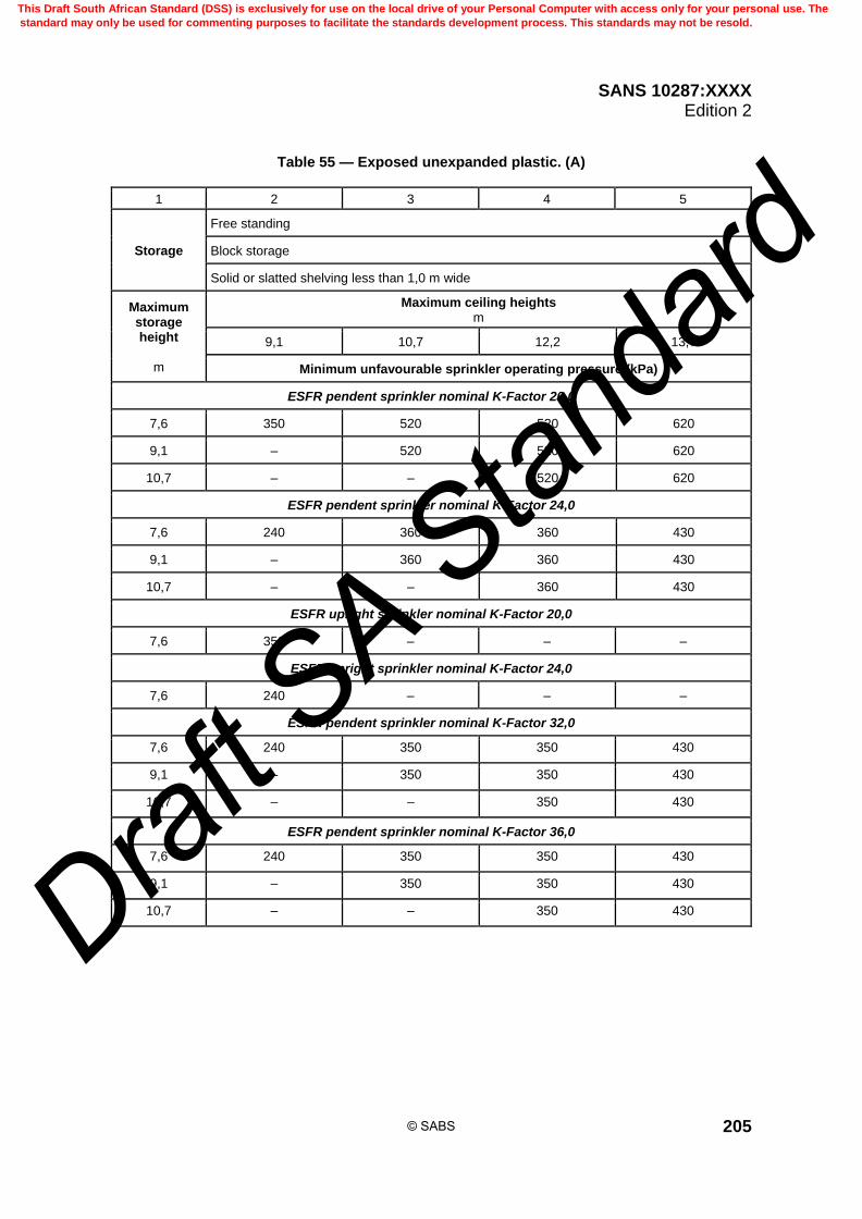
SANS 10287:XXXX Edition 2
205
Table 55 — Exposed unexpanded plastic. (A)
1 2 3 4 5
Storage
Free standing
Block storage
Solid or slatted shelving less than 1,0 m wide
Maximum storage height
m
Maximum ceiling heights m
9,1 10,7 12,2 13,7
Minimum unfavourable sprinkler operating pressure (kPa)
ESFR pendent sprinkler nominal K-Factor 20,0
7,6 350 520 520 620
9,1 – 520 520 620
10,7 – – 520 620
ESFR pendent sprinkler nominal K-Factor 24,0
7,6 240 360 360 430
9,1 – 360 360 430
10,7 – – 360 430
ESFR upright sprinkler nominal K-Factor 20,0
7,6 350 – – –
ESFR upright sprinkler nominal K-Factor 24,0
7,6 240 – – –
ESFR pendent sprinkler nominal K-Factor 32,0
7,6 240 350 350 430
9,1 – 350 350 430
10,7 – – 350 430
ESFR pendent sprinkler nominal K-Factor 36,0
7,6 240 350 350 430
9,1 – 350 350 430
10,7 – – 350 430
© SABS
This Draft South African Standard (DSS) is exclusively for use on the local drive of your Personal Computer with access only for your personal use. The
standard may only be used for commenting purposes to facilitate the standards development process. This standards may not be resold.
Draft S
A Stan
dard

SANS 10287:XXXX Edition 2
206
Table 56 — Exposed unexpanded plastic. (B)
1 2 3 4 5
Storage
Post pallets in single rows with aisles not less than 2,4 m wide
Post pallets in multiple (including double) rows
Beam pallet racking
Maximum storage height
m
Maximum ceiling heights m
9,1 10,7 12,2 13,7
Minimum unfavourable sprinkler operating pressure (kPa)
ESFR pendent sprinkler nominal K-Factor 20,0
7,6 350 520 520 620 + 1 level of in-rack
9,1 – 520 520 620 + 1 level of in-rack
10,7 – – 520 620 + 1 level of in-rack
12,2 – – – 620 + 1 level of in-rack
ESFR pendent sprinkler nominal K-Factor 24,0
7,6 240 360 410 430 + 1 level of in-rack
9,1 – 360 410 430 + 1 level of in-rack
10,7 – – 410 430 + 1 level of in-rack
12,2 – – – 430 + 1 level of in-rack
ESFR pendent sprinkler nominal K-Factor 32,0
7,6 240 350 410 430 + 1 level of in-rack
9,1 – 350 410 430 + 1 level of in-rack
10,7 – – 410 430 + 1 level of in-rack
12,2 – – – 430 + 1 level of in-rack
ESFR pendent sprinkler nominal K-Factor 36,0
7,6 240 350 410 430 + 1 level of in-rack
9,1 – 350 410 430 + 1 level of in-rack
10,7 – – 410 430 + 1 level of in-rack
12,2 – – – 430 + 1 level of in-rack
© SABS
This Draft South African Standard (DSS) is exclusively for use on the local drive of your Personal Computer with access only for your personal use. The
standard may only be used for commenting purposes to facilitate the standards development process. This standards may not be resold.
Draft S
A Stan
dard

SANS 10287:XXXX Edition 2
207
Table 57 — Expanded plastic in cartons. (A)
1 2 3 4 5
Storage
Free standing
Block storage
Solid or slatted shelving less than 1,0 m wide
Maximum storage height
m
Maximum ceiling height m
9,1 10,7 12,2 13,7
Minimum unfavourable sprinkler operating pressure (kPa)
ESFR pendent sprinkler nominal K-Factor 20,0
7,6 350 – – –
ESFR pendent sprinkler nominal K-Factor 24,0
7,6 240 – – –
ESFR upright sprinkler nominal K-Factor 20,0
7,6 350 – – –
ESFR upright sprinkler nominal K-Factor 24,0
7,6 240 – – –
ESFR pendent sprinkler nominal K-Factor 32,0
7,6 240 – – –
ESFR pendent sprinkler nominal K-Factor 36,0
7,6 240 – – –
© SABS
This Draft South African Standard (DSS) is exclusively for use on the local drive of your Personal Computer with access only for your personal use. The
standard may only be used for commenting purposes to facilitate the standards development process. This standards may not be resold.
Draft S
A Stan
dard

SANS 10287:XXXX Edition 2
208
Table 58 — Expanded plastic in cartons. (B)
1 2 3 4 5
Storage
Post pallets in single rows with aisles not less than 2,4 metres wide
Post pallets in multiple (including double) rows
Beam pallet racking
Maximum storage height
m
Maximum ceiling heights m
9,1 10,7 12,2 13,7
Minimum unfavourable sprinkler operating pressure (kPa)
ESFR pendent sprinkler nominal K-Factor 20,0
7,6 350 – – –
ESFR pendent sprinkler nominal K-Factor 24,0
7,6 240 – – –
ESFR upright sprinkler nominal K-Factor 20,0
7,6 350 – – –
ESFR upright sprinkler nominal K-Factor 24,0
7,6 240 – – –
ESFR pendent sprinkler nominal K-Factor 32,0
7,6 240 – – –
ESFR pendent sprinkler nominal K-Factor 36,0
7,6 240 – – –
© SABS
This Draft South African Standard (DSS) is exclusively for use on the local drive of your Personal Computer with access only for your personal use. The
standard may only be used for commenting purposes to facilitate the standards development process. This standards may not be resold.
Draft S
A Stan
dard
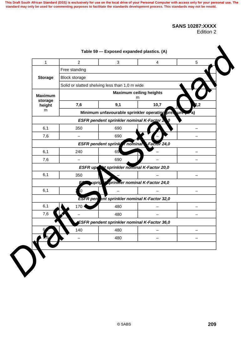
SANS 10287:XXXX Edition 2
209
Table 59 — Exposed expanded plastics. (A)
1 2 3 4 5
Storage
Free standing
Block storage
Solid or slatted shelving less than 1,0 m wide
Maximum storage height
m
Maximum ceiling heights m
7,6 9,1 10,7 12,2
Minimum unfavourable sprinkler operating pressure (kPa)
ESFR pendent sprinkler nominal K-Factor 20,0
6,1 350 690 – –
7,6 – 690 – –
ESFR pendent sprinkler nominal K-Factor 24,0
6,1 240 690 – –
7,6 – 690 – –
ESFR upright sprinkler nominal K-Factor 20,0
6,1 350 – – –
ESFR upright sprinkler nominal K-Factor 24,0
6,1 240 – – –
ESFR pendent sprinkler nominal K-Factor 32,0
6,1 170 480 – –
7,6 – 480 – –
ESFR pendent sprinkler nominal K-Factor 36,0
6,1 140 480 – –
7,6 – 480 – –
© SABS
This Draft South African Standard (DSS) is exclusively for use on the local drive of your Personal Computer with access only for your personal use. The
standard may only be used for commenting purposes to facilitate the standards development process. This standards may not be resold.
Draft S
A Stan
dard

SANS 10287:XXXX Edition 2
210
Table 60 — Exposed expanded plastics. (B)
1 2 3 4 5
Storage
Post pallets in single rows with aisles not less than 2,4 metres wide
Post pallets in multiple (including double) rows
Beam pallet racking
Maximum storage height
(metres)
Maximum ceiling heights (m)
7,6 9,1 10,7 12,2
Minimum unfavourable sprinkler operating pressure (kPa)
ESFR pendent sprinkler nominal K-Factor 20,0
6,1 520 690 – –
7,6 – 690 – –
ESFR pendent sprinkler nominal K-Factor 24,0
6,1 360 480 – –
7,6 – 480 – –
ESFR pendent sprinkler nominal K-Factor 32,0
6,1 360 480 – –
7,6 – 480 – –
ESFR pendent sprinkler nominal K-Factor 36,0
6,1 360 480 – –
7,6 – 480 – –
© SABS
This Draft South African Standard (DSS) is exclusively for use on the local drive of your Personal Computer with access only for your personal use. The
standard may only be used for commenting purposes to facilitate the standards development process. This standards may not be resold.
Draft S
A Stan
dard
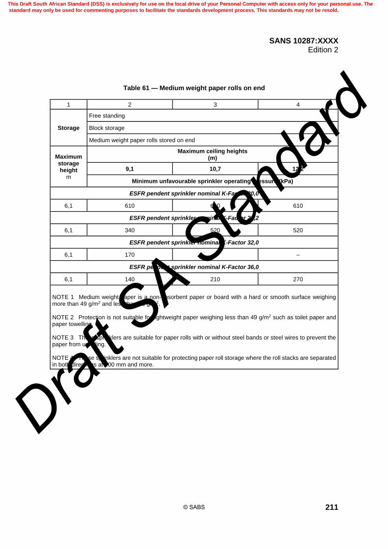
SANS 10287:XXXX Edition 2
211
Table 61 — Medium weight paper rolls on end
1 2 3 4
Storage
Free standing
Block storage
Medium weight paper rolls stored on end
Maximum storage height
m
Maximum ceiling heights (m)
9,1 10,7 12,2
Minimum unfavourable sprinkler operating pressure (kPa)
ESFR pendent sprinkler nominal K-Factor 20,0
6,1 610 610 610
ESFR pendent sprinkler nominal K-Factor 24,2
6,1 340 520 520
ESFR pendent sprinkler nominal K-Factor 32,0
6,1 170 – –
ESFR pendent sprinkler nominal K-Factor 36,0
6,1 140 210 270
NOTE 1 Medium weight paper is a non-absorbent paper or board with a hard or smooth surface weighing more than 49 g/m2 and less than 98 g/m2. NOTE 2 Protection is not suitable for lightweight paper weighing less than 49 g/m2 such as toilet paper and paper towelling. NOTE 3 These sprinklers are suitable for paper rolls with or without steel bands or steel wires to prevent the paper from unrolling. NOTE 4 These sprinklers are not suitable for protecting paper roll storage where the roll stacks are separated in both directions at 100 mm and more.
© SABS
This Draft South African Standard (DSS) is exclusively for use on the local drive of your Personal Computer with access only for your personal use. The
standard may only be used for commenting purposes to facilitate the standards development process. This standards may not be resold.
Draft S
A Stan
dard
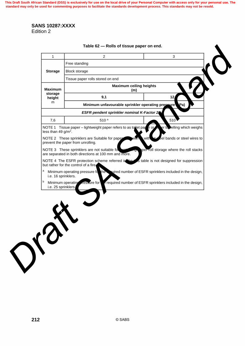
SANS 10287:XXXX Edition 2
212
Table 62 — Rolls of tissue paper on end.
1 2 3
Storage
Free standing
Block storage
Tissue paper rolls stored on end
Maximum storage height
m
Maximum ceiling heights (m)
9,1 12,2
Minimum unfavourable sprinkler operating pressure (kPa)
ESFR pendent sprinkler nominal K-Factor 20,0
7,6 510 a 510 b
NOTE 1 Tissue paper – lightweight paper refers to as toilet paper or paper towelling which weighs less than 49 g/m2.
NOTE 2 These sprinklers are Suitable for paper rolls with or without steel bands or steel wires to prevent the paper from unrolling.
NOTE 3 These sprinklers are not suitable for protecting paper roll storage where the roll stacks are separated in both directions at 100 mm and more.
NOTE 4 The ESFR protection scheme referred in the this table is not designed for suppression but rather for the control of a fire.
a Minimum operating pressure for the required number of ESFR sprinklers included in the design,
i.e. 16 sprinklers.
b Minimum operating pressure for the required number of ESFR sprinklers included in the design,
i.e. 25 sprinklers.
© SABS
This Draft South African Standard (DSS) is exclusively for use on the local drive of your Personal Computer with access only for your personal use. The
standard may only be used for commenting purposes to facilitate the standards development process. This standards may not be resold.
Draft S
A Stan
dard

SANS 10287:XXXX Edition 2
213
Table 63 — Heavy weight paper rolls stored on end.
1 2 3 4
Storage
Free standing
Block storage
Heavy weight paper rolls stored on end
Maximum storage
eight m
Maximum ceiling heights m
9,1 10,7 12,2
Minimum unfavourable sprinkler operating pressure (kPa)
ESFR pendent sprinkler nominal K-Factor 20,0
7,6 340 520 520
9,1 - 520 520
ESFR pendent sprinkler nominal K-Factor 24,2
7,6 240 360 360
9,1 – 360 360
NOTE 1 Heavy weight paper is a non-absorbent paper or board weighing 98 g/m2 or more.
NOTE 2 Where the paper roll stacks are separated in both directions by 100 mm or more the paper roll should have steel bands or steel wires to prevent the paper from unrolling, otherwise the protection is suitable for paper rolls with or without steel bands or steel wires.
© SABS
This Draft South African Standard (DSS) is exclusively for use on the local drive of your Personal Computer with access only for your personal use. The
standard may only be used for commenting purposes to facilitate the standards development process. This standards may not be resold.
Draft S
A Stan
dard

SANS 10287:XXXX Edition 2
214
Table 64 — Plastic coated heavy weight paper rolls stored on end.
1 2 3 4
Storage
Free standing
Block storage
Plastic coated heavy weight paper rolls stored on end
Maximum storage height
m
Maximum ceiling heights m
9,1 10,7 12,2
Minimum unfavourable sprinkler operating pressure (kPa)
ESFR pendent sprinkler nominal K-Factor 20,0
6,1 340 520 520
ESFR pendent sprinkler nominal K-Factor 24,2
6,1 240 360 360
NOTE 1 Heavy weight paper is a non-absorbent paper or board weighing 98 g/m2 or more.
NOTE 2 Where the paper roll stacks are separated in both directions by 100 mm or more the paper roll should have steel bands or steel wires to prevent the paper from unrolling, otherwise the protection is suitable for paper rolls with or without steel bands or steel wires.
© SABS
This Draft South African Standard (DSS) is exclusively for use on the local drive of your Personal Computer with access only for your personal use. The
standard may only be used for commenting purposes to facilitate the standards development process. This standards may not be resold.
Draft S
A Stan
dard

SANS 10287:XXXX Edition 2
215
Table 65 — Rubber tyres.
1 2 3
Storage
Open bottom post pallets in multiple rows
Open bottom palletised racking system
Maximum storage height
m
Maximum ceiling heights m
9,1 12,2
Minimum unfavourable sprinkler operating pressure (kPa)
ESFR pendent sprinkler nominal K-Factor 20,0
7,6 350 –
ESFR pendent sprinkler nominal K-Factor 24,2
7,6 240 –
ESFR pendent sprinkler nominal K-Factor 32,0
7,6 170 –
ESFR pendent sprinkler nominal K-Factor 36,0
7,6 140 –
9,1 – 520
NOTE Tyres may be stored on side or on tread, but not laced.
Table 66 — Various commodities on mezzanines. (A)
1 2
Storage Free standing
Block storage
Commodities
Unexpanded plastics cartoned
Exposed unexpanded plastics
Expanded plastics cartoned
Exposed expanded plastics
Medium weight paper rolls stored on end (See table 61)
Maximum storage height not greater than roof or ceiling height minus 1,0 m
Maximum ceiling heights m
≤ 4,5
Minimum unfavourable sprinkler operating pressure (kPa)
ESFR pendent sprinkler nominal K-Factor 20,0
350
© SABS
This Draft South African Standard (DSS) is exclusively for use on the local drive of your Personal Computer with access only for your personal use. The
standard may only be used for commenting purposes to facilitate the standards development process. This standards may not be resold.
Draft S
A Stan
dard

SANS 10287:XXXX Edition 2
216
Table 67 — Various commodities on mezzanines. (B)
1 2
Storage Post pallets in multiple rows
Palletised racking
Commodities
Unexpanded plastics cartoned
Exposed unexpanded plastics
Expanded plastics cartoned
Exposed expanded plastics
Maximum storage height not greater than roof or ceiling height minus 1,0 m
Maximum ceiling heights m
≤ 4,5
Minimum unfavourable sprinkler operating pressure (kPa)
ESFR pendent sprinkler nominal K-Factor 20,0
350
ESFR pendent sprinkler nominal K-Factor 24,0
240
© SABS
This Draft South African Standard (DSS) is exclusively for use on the local drive of your Personal Computer with access only for your personal use. The
standard may only be used for commenting purposes to facilitate the standards development process. This standards may not be resold.
Draft S
A Stan
dard
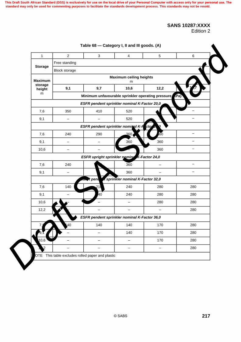
SANS 10287:XXXX Edition 2
217
Table 68 — Category I, II and III goods. (A)
1 2 3 4 5 6
Storage Free standing
Block storage
Maximum storage height
m
Maximum ceiling heights m
9,1 9,7 10,6 12,2 13,7
Minimum unfavourable sprinkler operating pressure (kPa)
ESFR pendent sprinkler nominal K-Factor 20,0
7,6 350 410 520 – –
9,1 – – 520 – –
ESFR pendent sprinkler nominal K-Factor 24,0
7,6 240 290 360 360 –
9,1 – – 360 360 –
10,6 – – – 360 –
ESFR upright sprinkler nominal K-Factor 24,0
7,6 240 290 360 – –
9,1 – – 360 – –
ESFR pendent sprinkler nominal K-Factor 32,0
7,6 140 210 240 280 280
9,1 – 240 240 280 280
10,6 – – – 280 280
12,2 – – – – 280
ESFR pendent sprinkler nominal K-Factor 36,0
7,6 140 140 140 170 280
9,1 – – 140 170 280
10,6 – – – 170 280
12,2 – – – – 280
NOTE This table excludes rolled paper and plastic
© SABS
This Draft South African Standard (DSS) is exclusively for use on the local drive of your Personal Computer with access only for your personal use. The
standard may only be used for commenting purposes to facilitate the standards development process. This standards may not be resold.
Draft S
A Stan
dard
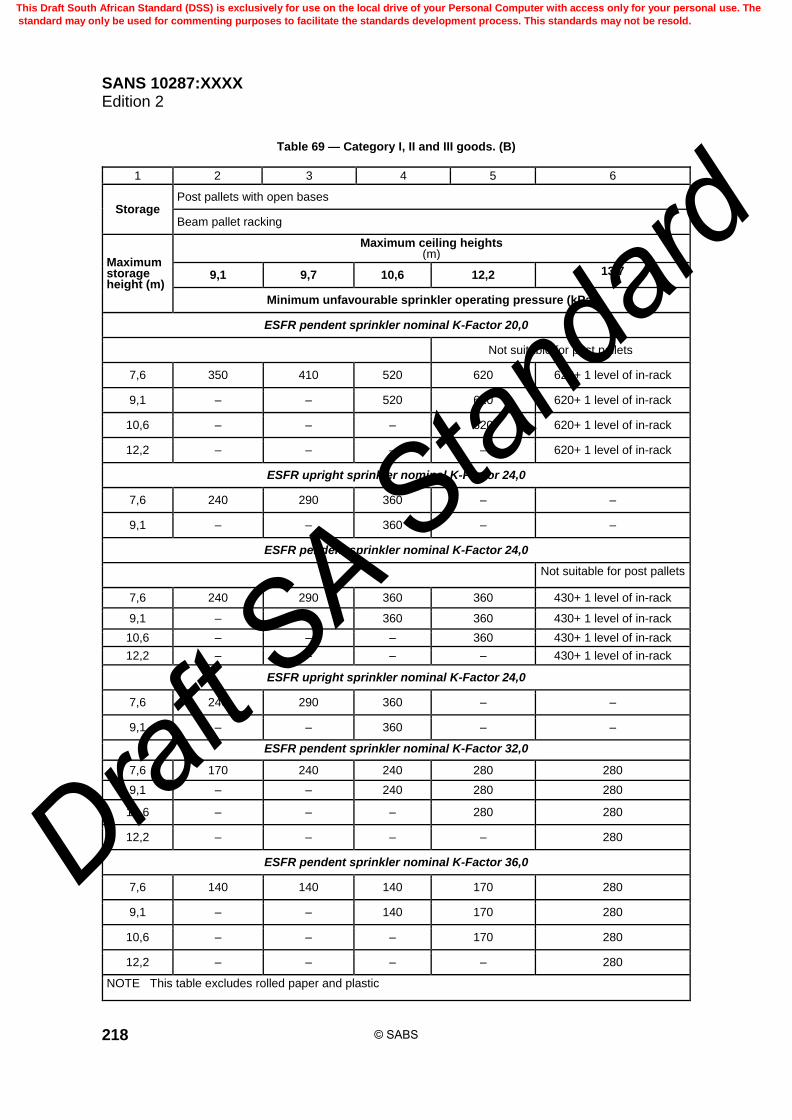
SANS 10287:XXXX Edition 2
218
Table 69 — Category I, II and III goods. (B)
1 2 3 4 5 6
Storage Post pallets with open bases
Beam pallet racking
Maximum storage height (m)
Maximum ceiling heights (m)
9,1 9,7 10,6 12,2 13,7
Minimum unfavourable sprinkler operating pressure (kPa)
ESFR pendent sprinkler nominal K-Factor 20,0
Not suitable for post pallets
7,6 350 410 520 620 620+ 1 level of in-rack
9,1 – – 520 620 620+ 1 level of in-rack
10,6 – – – 620 620+ 1 level of in-rack
12,2 – – – – 620+ 1 level of in-rack
ESFR upright sprinkler nominal K-Factor 24,0
7,6 240 290 360 – –
9,1 – – 360 – –
ESFR pendent sprinkler nominal K-Factor 24,0
Not suitable for post pallets
7,6 240 290 360 360 430+ 1 level of in-rack
9,1 – – 360 360 430+ 1 level of in-rack
10,6 – – – 360 430+ 1 level of in-rack
12,2 – – – – 430+ 1 level of in-rack
ESFR upright sprinkler nominal K-Factor 24,0
7,6 240 290 360 – –
9,1 – – 360 – –
ESFR pendent sprinkler nominal K-Factor 32,0
7,6 170 240 240 280 280
9,1 – – 240 280 280
10,6 – – – 280 280
12,2 – – – – 280
ESFR pendent sprinkler nominal K-Factor 36,0
7,6 140 140 140 170 280
9,1 – – 140 170 280
10,6 – – – 170 280
12,2 – – – – 280
NOTE This table excludes rolled paper and plastic
© SABS
This Draft South African Standard (DSS) is exclusively for use on the local drive of your Personal Computer with access only for your personal use. The
standard may only be used for commenting purposes to facilitate the standards development process. This standards may not be resold.
Draft S
A Stan
dard

SANS 10287:XXXX Edition 2
219
17.8 Roof or ceilings
17.8.1 Only non-combustible roof insulation that complies with the relevant testing standards shall be installed at roof or ceiling level.
17.8.2 The ceiling slope influences the movement of hot gases across the ceiling and therefore influences the operation of the sprinkler heads during a fire. Excessive ceiling slope may result in the operation of sprinklers remote from the fire whilst delaying the operation of those sprinklers in close proximity to the fire.
17.8.3 The roof or ceiling slope shall not exceed 9,5, (170 mm per metre).
17.8.4 Where the roof or ceiling slope exceeds 9,5, the roof or ceiling shall be under drawn with a false ceiling. The false ceiling shall be of non-combustible construction, with an acceptable slope. ESFR sprinklers shall be deployed below the false ceiling. Standard sprinkler protection shall be employed in the roof or ceiling space in accordance with this standard.
17.8.5 Ceilings and any sub-ceilings shall be firmly secured and shall be capable of withstanding a vertical upward thrust of 50 N/m2.
17.8.6 Ceiling materials considered suitable are 10 mm gypsum board, corrugated and sheet steel and mineral tiles.
17.8.7 Roof lights shall be flush to the ceiling or under drawn at ceiling level.
17.8.8 Roof lights shall be capable of withstanding a temperature of 300 °C for a period of not less than 15 min.
17.9 Ventilation Automatic ventilation or open natural ventilation shall not be installed in conjunction with ESFR sprinkler protection. If roof vents or other roof openings are unavoidable, they shall be operated manually.
17.10 Powered ventilation – High Volume Low Speed Fans Where High Volume Low Speed (HVLS) fans are installed in buildings protected with ESFR sprinklers, the following shall be complied with: a) the maximum fan diameter shall be 3,7 m; b) HVLS fans shall be centred between four sprinklers; c) the vertical distance between HVLS fan blades to sprinkler deflector shall be ≥ 0,9 m; d) all HVLS shall be shut down immediately upon sprinkler or fire alarm detection (whichever occurs
first). Where ESFR sprinkler protection is to be employed, any ventilation openings at roof level shall close automatically upon sprinkler or fire alarm detection (whichever occurs first). Powered ventilation systems shall be shut down immediately upon sprinkler or fire alarm detection (whichever occurs first).
© SABS
This Draft South African Standard (DSS) is exclusively for use on the local drive of your Personal Computer with access only for your personal use. The
standard may only be used for commenting purposes to facilitate the standards development process. This standards may not be resold.
Draft S
A Stan
dard

SANS 10287:XXXX Edition 2
220
Powered ventilators and fire dampers should be stopped before the first sprinkler operates. Fire detection systems should be either: a) aspirating smoke detectors installed in all ventilation ducts extracting from the ESFR protected risk;
or b) a fire detection system of detection performance equivalent to an aspirating smoke detection
system.
17.11 Installation types
17.11.1 Sprinkler protection shall only be installed on the wet pipe system.
17.11.2 Sprinklers shall be approved to the relevant standard.
17.11.3 The sprinklers used shall be in accordance with table 70.
Table 70 — Sprinkler nominal K-Factor and shank thread relationship
1 2 3
Sprinkler nominal K-factor
Sprinkler pattern Sprinkler shank thread
mm
11,5 Spray 20
20,0 and 24,2 ESFR 20
32,0 and 36,0 ESFR 25
17.11.4 ESFR sprinklers and any spray pattern sprinklers below walkways and mezzanine shall have a fast response thermal sensitivity rating.
17.11.5 All sprinklers shall have one of the temperature ratings given in table 71 and shall be correspondingly colour-coded.
Table 71 — ESFR sprinkler temperature ratings and colour coding
1 2 3 4
Glass bulb sprinklers Fusible link sprinklers
Temperature rating Colour of bulb liquid
Temperature rating Colour of yoke arms C C
68 Red 68 to 74 Uncoloured
93 Green 93 to 104 White
17.11.6 Under ambient temperature the 74o C operating temperature sprinkler shall be used and the higher temperature ratings shall only be used where needed due to high ambient temperature conditions.
© SABS
This Draft South African Standard (DSS) is exclusively for use on the local drive of your Personal Computer with access only for your personal use. The
standard may only be used for commenting purposes to facilitate the standards development process. This standards may not be resold.
Draft S
A Stan
dard

SANS 10287:XXXX Edition 2
221
17.12 ESFR sprinkler location relative to obstructions at or near the ceiling or roof
17.12.1 ESFR sprinklers shall be located at the appropriate horizontal distance from obstructions at the ceiling and roof such as beams, ducts, joists, distribution pipes, range pipes or light fittings as given in table 72.
17.12.2 ESFR sprinklers shall be located no closer than 100 mm horizontally from the bottom nearside edge of joists, trusses or similar obstructions. In some instances it may be advantageous to vary ESFR sprinkler spacing across the ceilings to avoid obstructions to the sprinkler water distribution.
17.12.3 In the case of upright ESFR sprinklers, obstructions not exceeding 100 mm in width can be located directly below the sprinkler deflector. Upright sprinklers can be installed on range pipes up to and including 80 mm (outside diameter) without the need for risers to raise the sprinkler above the range pipe.
Table 72 — ESFR sprinkler location relative to ceiling obstructions
1 2 3
Distance "a"a Distance "b" a
Minimum horizontal distance from sprinkler axis to side obstruction
Maximum height of ESFR sprinkler deflector above (+)
bottom of obstruction Greater than Less than
mm mm mm
100 300 0
300 500 40
500 600 75
600 800 140
800 900 200
900 1 100 250
1 100 1 200 300
1 200 1 400 380
1 400 1 500 460
1 500 1 700 560
1 700 1 800 660
1 800 1 850 790
a See figure 43 for ESFR sprinkler locations relative to ceiling obstructions.
© SABS
This Draft South African Standard (DSS) is exclusively for use on the local drive of your Personal Computer with access only for your personal use. The
standard may only be used for commenting purposes to facilitate the standards development process. This standards may not be resold.
Draft S
A Stan
dard

SANS 10287:XXXX Edition 2
222
Figure 43 — ESFR sprinkler locations relative to ceiling obstructions
17.13 Calculation parameters
17.13.1 ESFR sprinkler systems flow and pressure demand shall be hydraulically calculated in accordance with this standard.
17.13.2 ESFR sprinkler systems shall be fed from a pumped water supply operating under positive head conditions. A duplicate water supply is strongly recommended.
17.13.3 The minimum nominal bore of any range pipe shall not be less than 25 mm.
17.13.4 The maximum nominal bore of any range pipe shall not exceed 100 mm.
17.13.5 The calculated discharge pressure of any ESFR sprinkler, when all the sprinklers in the assumed maximum number of sprinklers operating plus any additional sprinklers under obstructions are operating shall not be less than that given within the applicable tables used relating to ESFR sprinklers in this standard.
17.13.6 Any additional ESFR sprinklers beneath obstructions, walkways and conveyors may be disregarded in hydraulic calculations.
17.13.7 The number of sprinklers in the assumed maximum number of sprinklers operating shall be 12, except for mezzanines less than 4,0 m high where the assumed maximum number of sprinklers operating shall be 6, plus any additional sprinklers deemed to be operating such as sprinklers under obstructions, walkways or conveyors or intermediate level sprinklers.
17.13.8 For hydraulic calculation purposes, the assumed maximum number of sprinklers operating of 12 sprinkler heads and any in-rack sprinklers shall be located at the hydraulically most unfavourable location based upon the balanced calculation for the 12 ceiling sprinklers plus any in-rack sprinklers included.
17.13.9 Any additional ESFR sprinklers beneath obstructions within the assumed maximum area of operation shall be assumed to be in simultaneous operation at a pressure of not less than that specified for the ESFR sprinkler as specified in this standard.
© SABS
This Draft South African Standard (DSS) is exclusively for use on the local drive of your Personal Computer with access only for your personal use. The
standard may only be used for commenting purposes to facilitate the standards development process. This standards may not be resold.
Draft S
A Stan
dard

SANS 10287:XXXX Edition 2
223
17.13.10 The shape of the assumed maximum area of operation shall be taken as four adjacent sprinklers on a range operating on each of three adjacent range pipes plus any additional sprinklers beneath or above the assumed maximum area of operation.
17.13.11 Where ESFR sprinklers are used to protect storage areas beneath mezzanines and where the assumed maximum number of sprinklers deemed to be in simultaneous operation is reduced to 6 ESFR sprinklers, then 3 adjacent sprinklers on a range shall be assumed to operate on each of 2 adjacent ranges.
17.13.12 Where range pipes have fewer than the designated number of ESFR sprinklers per range, for example, fed from an end-side arrangement, all adjacent sprinklers on a range are assumed to be in simultaneous operation and the number of adjacent ranges shall be increased to compensate.
17.13.13 Changes in sprinkler spacing, array design, elevation, range spacing as well as possible location, whether on or between distribution pipes, shall be considered for the hydraulically most unfavourable location of the assumed maximum number of sprinklers operating.
17.13.14 Full calculation for each possible location is necessary except where it is obvious that an array is similar to another array under consideration and hydraulically nearer the water supply.
17.13.15 Continuous operation of the assumed maximum number of sprinklers operating at the hydraulically most unfavourable location creates the most adverse pressure. This is used to establish that the minimum ESFR sprinkler flow pressure is achieved.
17.13.16 Changes in sprinkler spacing, array design, elevation, range spacing as well as possible location, whether on or between distribution pipes shall be considered for the hydraulically most favourable location of the assumed maximum number of sprinklers operating.
17.13.17 Continuous operation of the assumed maximum number of sprinklers operating at the hydraulically most favourable location defines the flow rate which is used to determine that the pipework design is compatible with the water supply pressure flow characteristic.
17.13.18 Proof of correct position in grid systems is established by displacing the assumed maximum area of operation by one sprinkler pitch in each direction along ranges and by one range pipe in each direction along distribution pipes.
17.13.19 Any additional ESFR sprinklers beneath obstructions within the assumed maximum number of sprinklers operating shall be assumed to be operating, at not less than the specified ESFR sprinkler flow pressure as defined in the tables relating to this protection.
17.14 Sprinklers beneath walkways and conveyors
17.14.1 Walkways and conveyors exceeding 3,0 m in width shall be treated as a mezzanine.
17.14.2 Where sprinklers are installed below walkways as specified in this standard, two sprinklers shall be assumed to be in simultaneous operation at a pressure as given in table 73.
17.14.3 It shall be assumed that the ceiling sprinklers and two sprinklers beneath each walkway in the assumed maximum area of operation are in simultaneous operation.
17.14.4 Elevated walkways, conveyors or similar obstructions shall not be used within racking and aisles.
© SABS
This Draft South African Standard (DSS) is exclusively for use on the local drive of your Personal Computer with access only for your personal use. The
standard may only be used for commenting purposes to facilitate the standards development process. This standards may not be resold.
Draft S
A Stan
dard

SANS 10287:XXXX Edition 2
224
17.14.5 Elsewhere, walkways and conveyors, not exceeding 3,0 m width, shall be protected underneath by a centrally located single row of ESFR sprinklers or spray pattern sprinklers. The sprinklers shall be spaced not more than 3,0 m apart. Walkways and conveyors exceeding 3,0 m width shall be treated as mezzanines.
Table 73 — Minimum operating pressure for sprinklers beneath walkways and conveyors
1 2 3
Sprinkler nominal K-factor Sprinkler pattern Minimum operating pressure
kPa
11,5 Spray 350
20,0 ESFR 350
24,2 ESFR 240
32,0 ESFR 170
36,0 ESFR 140
17.15 Sprinkler protection beneath mezzanines
17.15.1 Where mezzanines exist, they shall be continuous throughout the extent that they feature in the building. Penetrations through the mezzanine shall be adequately fire-stopped. Draught or smoke curtains of depth at least 600 mm shall be installed at the open face perimeter of the mezzanine.
17.15.2 Where the height of the mezzanine level(s) exceeds 4,5 m, the underside of the mezzanine shall be protected by ESFR sprinklers. Where the height of the mezzanines level(s) above the floor is 4,5 m or less, ESFR or appropriate spray pattern sprinkler protection may be employed.
17.15.3 Where spray pattern sprinkler protection is used below low mezzanines, it shall comply with 6.10 and 6.11.
17.15.4 Where mezzanines have openings into the protected building, the storage beneath the mezzanine shall not be closer to the open face than within the bounds of a 600 mm deep draught or smoke curtain.
17.16 Sprinkler spacing and location
17.16.1 ESFR sprinklers shall be installed in a standard and uniform layout pattern.
17.16.2 The area coverage and spacing of ESFR sprinklers shall comply with table 74.
17.16.3 Sprinklers shall be located beneath the ceiling in accordance with table 75.
Table 74 — ESFR sprinkler spacing
1 2 3 4 5
Ceiling height Distance between sprinklers Area of coverage per sprinkler
Min. Max. Min. Max.
m m m m2 m2
≤ 9 2,4 3,7 7,5 9,0
> 9 ≤ 13,7 2,4 3,0 7,5 9,0
© SABS
This Draft South African Standard (DSS) is exclusively for use on the local drive of your Personal Computer with access only for your personal use. The
standard may only be used for commenting purposes to facilitate the standards development process. This standards may not be resold.
Draft S
A Stan
dard

SANS 10287:XXXX Edition 2
225
Table 75 — Sprinkler distance from underside of ceiling
1 2 3 4
Sprinkler nominal K-factor
Sprinkler pattern
Vertical distance from the underside of the ceiling to the sprinkler deflector
Not less than Not more than
mm mm
11,5 Spray 75 150
20,0 and 24,2 (pendant) ESFR 150 350
32,0 and 36,0 (pendant) ESFR 150 460
20,0 and 24,2 (upright) ESFR 75 300
17.16.4 Where roofs or ceilings are constructed using beams and girders or profile panelling, sprinklers shall be located in bays rather than under beams. Bays formed by these methods of ceiling construction shall not exceed 750 mm in depth.
17.16.5 Where the ceiling is profiled, the distance from the ceiling shall be measured from the top of the profile. The deflector position relative to the ceiling profiling shall comply with table 75.
17.16.6 ESFR sprinklers shall be installed with the waterway axes perpendicular to the floor, except that where the ceiling slope is less than or equal to 5° from horizontal it shall also be acceptable for them to be installed with the waterway axes perpendicular to the ceiling.
17.16.7 Throughout the protected area and regardless of hazard rating or occupancy, the clear space below an ESFR sprinkler shall not be less than 1,0 m.
17.16.8 Where draught or smoke curtains are fitted at the ceiling level, the draught or smoke curtain shall be treated as a boundary.
17.16.9 Areas of ESFR protection shall not be subdivided by draught curtains, smoke curtains or barriers (except where required elsewhere in this standard, for example, in the case of the perimeter of mezzanines.
17.16.10 Where ESFR sprinkler protection adjoins areas protected by standard sprinklers, the following requirements shall be complied with: a) Where ESFR and the adjacent sprinklers are at the same ceiling height or where the ESFR
sprinklers are installed at a greater ceiling height than standard sprinklers, smoke and draught curtains shall be installed at the ceiling separating the ESFR and standard sprinklers. The smoke and draught curtains shall be at least 600 mm deep and shall be located at the midpoint between the ESFR and standard sprinklers. The smoke curtain shall be made of non-combustible material.
b) An aisle of not less than one 1,2 m wide, free of all stored goods, shall be maintained between
ESFR protected areas and those protected by standards sprinklers. The centre of the aisles shall coincide with the midpoint between the ESFR and standard sprinklers.
17.17 Intermediate sprinklers in ESFR occupancies Where indicated, ESFR protection specified in this standard, allows for extended storage heights in racks provided intermediate sprinkler protection is installed. Intermediate sprinklers shall be in accordance with the following requirements: a) at least one level of intermediate sprinklers shall be installed;
© SABS
This Draft South African Standard (DSS) is exclusively for use on the local drive of your Personal Computer with access only for your personal use. The
standard may only be used for commenting purposes to facilitate the standards development process. This standards may not be resold.
Draft S
A Stan
dard

SANS 10287:XXXX Edition 2
226
b) the vertical distance from floor to the intermediate sprinklers shall be half the rack height to within one tier height level;
c) intermediate sprinklers shall have the following properties:
1) spray pattern sprinklers;
2) K-Factor of 11,5;
3) fast response sprinkler with an RTI of less than 50;
4) nominal operating temperature of 68 °C;
5) be fitted with a 75 mm diameter metal water shield which is approved; and
6) be fitted with a sprinkler guard which is approved. d) be located within the longitudinal flue at each transverse flue intersection at a maximum spacing
of 1,5 m in either direction; e) at least eight intermediate sprinklers shall be assumed to be in simultaneous operation; f) the minimum pressure of any operating intermediate sprinklers shall not be less than 350 kPa; and g) the water supply shall have sufficient capacity of simultaneous operation of the roof level ESFR
sprinkler protection plus the flow requirement for the intermediate sprinklers.
18 Enhanced protection extended coverage (EPEC) sprinklers
18.1 General
18.1.1 The use of EPEC sprinklers, complying with relevant performance testing, allows increased sprinkler coverage in areas of up to 17,64 m2 per sprinkler. The protection described is based on extensive sprinkler tests involving the actual delivered density and commodity fire tests.
18.1.2 EPEC sprinklers have a nominal K-Factor of 11,5 and are developed for use at 17,64 m2. They have a significantly different water distribution characteristic from conventional and spray pattern sprinklers.
18.1.3 The reduced water supply storage volume is allowed as a result from the increased effectiveness of the sprinkler protection. The sprinkler may be identified by the marking "EPEC".
18.2 Design practice
18.2.1 The system design and general protection method shall be in accordance with this standard, except where otherwise specified in this sub-clause.
18.2.2 EPEC sprinkler installations shall also comply with any requirements or limitations stated in the sprinkler suppliers data sheet.
18.2.3 All pipe sizing shall be by hydraulic calculation.
18.2.4 Where dry-pipe sprinkler installations are to be used, the time for the water to discharge from any sprinkler in the installation shall be predicted by calculation at the design stage and shall not
© SABS
This Draft South African Standard (DSS) is exclusively for use on the local drive of your Personal Computer with access only for your personal use. The
standard may only be used for commenting purposes to facilitate the standards development process. This standards may not be resold.
Draft S
A Stan
dard

SANS 10287:XXXX Edition 2
227
exceed 30 s. It may be prudent to assume a time period of less than 30 s at design stage to ensure compliance when tested. On completion of the installation a discharge test shall be carried out at the remote sprinkler point in order to verify the time taken from operation of sprinkler to discharge of water.
18.3 Occupancy and fire hazard
18.3.1 The occupancies to be protected in accordance with the requirements of this standard shall be ordinary hazard in character and shall be subdivided into the following two groups: a) ordinary hazard 10,0 referred to as OH-10 in table 76, table 77 (determined using calculations in table 78 and table 79; b) ordinary hazard 12,5 referred to as OH-12,5 in table 76, table 77 (determined using calculations in table 78 and table 79.
18.3.2 The following conditions shall be met: a) the maximum storage heights specified in table 76 shall not be exceeded; b) the maximum storage area shall not exceed 100 m2 for any single block with less than 1,5 m
clearance around the block; c) the maximum ceiling height shall not exceed 5,5 m; d) the ceiling slope shall not exceed 9,5° (170 mm per metre); e) containers with an open top shall not be stored in the protected areas; and f) no process occupancy or special hazard shall be within the protected area.
Table 76 — Maximum storage heights for ordinary hazard EPEC protection
1 2 3 4 5
Type of installation
Maximum storage height
m
OH-10 Wet-pipe and pre-action OH-12,5 Dry-pipe systems
OH-12,5 Wet-pipe and pre-action systems
Storage category
Free standing or block storage
Beam pallet racking and shelf
storage
Free standing or
block storagea
Beam pallet racking and shelf
storagea
I 4,0 3,5 4,5 4,0
II 3,0 2,6 4,0 3,5
III 2,1 1,7 3,1 2,6
IV 1,2 1,2 1,5 1,5
a Storage to the height specified may not exceed 4 m2 in plan area. Category IV shall not include exposed
expanded plastics.
18.3.3 Storage in OH-12,5 protection, which exceeds the height for OH-10, shall not be greater than 4,0 m2 in plan area but may be contiguous with lower height storage allowed for OH-10.
© SABS
This Draft South African Standard (DSS) is exclusively for use on the local drive of your Personal Computer with access only for your personal use. The
standard may only be used for commenting purposes to facilitate the standards development process. This standards may not be resold.
Draft S
A Stan
dard

SANS 10287:XXXX Edition 2
228
18.3.4 Where there is more than one area of storage to these heights within a continuous block of storage, storage heights above the heights specified for OH-10 shall be separated by gaps of not less than 1,5 m.
18.3.5 The form of protection in 18.3.4 shall not be used where any of the following conditions occur: a) materials in which fires cannot readily be controlled by sprinklers, for example, acrylic fibre yarn
storage; b) commodities or storage arrangements which may give rise to unusually severe fire characteristics,
for example, lightweight paper storage; c) open top storage containers, for example, open top tote boxes; d) ceilings with joists, deep beams or significant obstructions; e) dry-pipe installations where the calculated time for water to discharge from any sprinkler in the
installation or the measured time from a test valve exceeds the maximum time allowable (30 s); and
f) a town main connection where the performance of the town main has not been verified by extensive
and comprehensive testing.
18.4 Sprinkler selection Sprinklers installed for ceiling or roof protection shall be classed as EPEC sprinklers with a nominal K-factor of 11,5 and shall be of the fast response type.
18.5 High and low flow conditions
18.5.1 The minimum design density and minimum sprinkler operating pressure shall not be less than the appropriate value given in table 77.
Table 77 — EPEC flow design criteria
1 2 3 4 5 6 7
Hazard classificati
on
Maximum area per sprinkler
Low flow conditions High flow conditions
Minimum operating sprinkler pressure
Number of sprinklers operating
Minimum design density
Assumed maximum area of operation
m2
Wet pipe and pre-action
type B installation
Dry pipe installation
m2 kPa mm/min
OH-10 ≤ 16 200 4 6,0 160 –
OH-12,5 ≤ 16 310 4 6,5 160 200
OH-10 > 16 ≤ 17,64 240 4 6,0 160 –
OH-12,5 > 16 ≤ 17,64 370 4 6,5 160 200
© SABS
This Draft South African Standard (DSS) is exclusively for use on the local drive of your Personal Computer with access only for your personal use. The
standard may only be used for commenting purposes to facilitate the standards development process. This standards may not be resold.
Draft S
A Stan
dard

SANS 10287:XXXX Edition 2
229
18.5.2 The minimum sprinkler operating pressure shall not be less than the values specified in table 77 for the low flow conditions when either all the sprinklers in the room or four sprinklers are operating, whichever is the least.
18.5.3 The minimum design density shall not be less than the values specified in table 77 for the high flow conditions when all the sprinklers in the room or the sprinklers in the areas specified are in operation, whichever is the least.
18.5.4 The shape of the high flow condition area shall comply with this standard and shall, where possible, encompass the number of sprinklers operating on a single range.
18.5.5 The shape of the low flow condition group of sprinklers used for hydraulic calculation purposes shall, where possible, be a square or rectangular.
18.5.6 In order to determine that the installation requirements are met, three sets of pressure and flow calculations given in table 78 shall be carried out.
Table 78 — Calculation of maximum flow demand, minimum allowable densities and pressures
1 2 3 4 5
Calculation set
Condition specified in
table 77
Assumed maximum area
of operation (Sprinklers operating)
Location of assumed maximum area of
operation or sprinklers operating
Calculation results
m2
Maximum demand flow
High flow condition
160 wet pipe 200 dry pipe
Hydraulically most favourable
Flow from sprinklers in the assumed maximum area of operation, any additional sprinklers
Minimum allowable density
High flow condition
160 wet pipe 200 dry pipe
Hydraulically most unfavourable
Density from hydraulically most unfavourable four sprinklers within the assumed maximum area of operation
Minimum sprinkler operating pressure
Low flow condition
4 sprinklers Hydraulically most
unfavourable
Sprinkler operating pressure for four sprinklers operating
18.6 Water supplies
18.6.1 The water supplies for the installation shall be capable of providing sufficient pressures and flows to satisfy the installation demand conditions determined by the calculations in table 78.
18.6.2 If the water supply is used by other fire-fighting systems, all qualifying conditions shall be complied with.
18.6.3 The duration of the water supply to the sprinkler installation shall be assumed to be 30 m or the duration required for the other fire-fighting systems, whichever is the greater.
18.6.4 Each water supply shall have sufficient capacity for the minimum duration required.
© SABS
This Draft South African Standard (DSS) is exclusively for use on the local drive of your Personal Computer with access only for your personal use. The
standard may only be used for commenting purposes to facilitate the standards development process. This standards may not be resold.
Draft S
A Stan
dard

SANS 10287:XXXX Edition 2
230
18.6.5 In the case of town mains and other inexhaustible water supplies, the duration is implicit for the requirements for those supplies.
18.6.6 The water supply shall be at least one of the following in accordance with this standard: a) town main; b) pump and tank; a) elevated private reservoir; or b) gravity tank.
18.6.7 The required water volume for the sprinkler installation shall be calculated by multiplying the maximum water flow demand by the required 30 min or the duration required for the other fire-fighting systems, whichever is the greater.
18.6.8 Where a town main is used either as a direct connection to the sprinkler system or for tank in-fill, the flow capacity of the town main shall be assumed to be not more than 75 % of the measured capability at a time of lowest flow capacity.
18.6.9 The lowest flow capacity of the town main may occur either at the time of the highest demand from users or may in some instances, occur at night depending on the water supplies pressure management strategy.
18.6.10 In the case of a pump a nominal rating of at least 120 % of the maximum demand flow at the high flow condition at a pressure of at least 50 % of the maximum demand flow pressure requirement shall be complied with.
18.6.11 The pump shall provide a pressure of at least 50 kPa higher than that required, when measured at the supplies test facility.
18.6.12 For suction pumps a water supply at the normal level shall be used to determine the rating.
18.7 Spacing and location of sprinklers
18.7.1 A clear space of at least 1,0 m shall be maintained below the deflector of roof or ceiling sprinklers.
18.7.2 The maximum area of coverage per sprinkler and spacing between sprinklers shall be in accordance with table 79.
18.7.3 Any sprinkler coverage of spacing recommendations or limitations specified in the supplies data sheet shall be complied with.
Table 79 — Maximum coverage and spacing between EPEC sprinklers
1 2 3 4 5
Hazard class
Maximum area per sprinkler
Maximum distances in accordance with this standard
Standard layout S and D
Staggered layout
m2 S D
OH-10 ≤ 16 4,2 4,6 5,3
OH-12,5 > 16 ≤ 17,64 4,2 4,6 5,9
© SABS
This Draft South African Standard (DSS) is exclusively for use on the local drive of your Personal Computer with access only for your personal use. The
standard may only be used for commenting purposes to facilitate the standards development process. This standards may not be resold.
Draft S
A Stan
dard
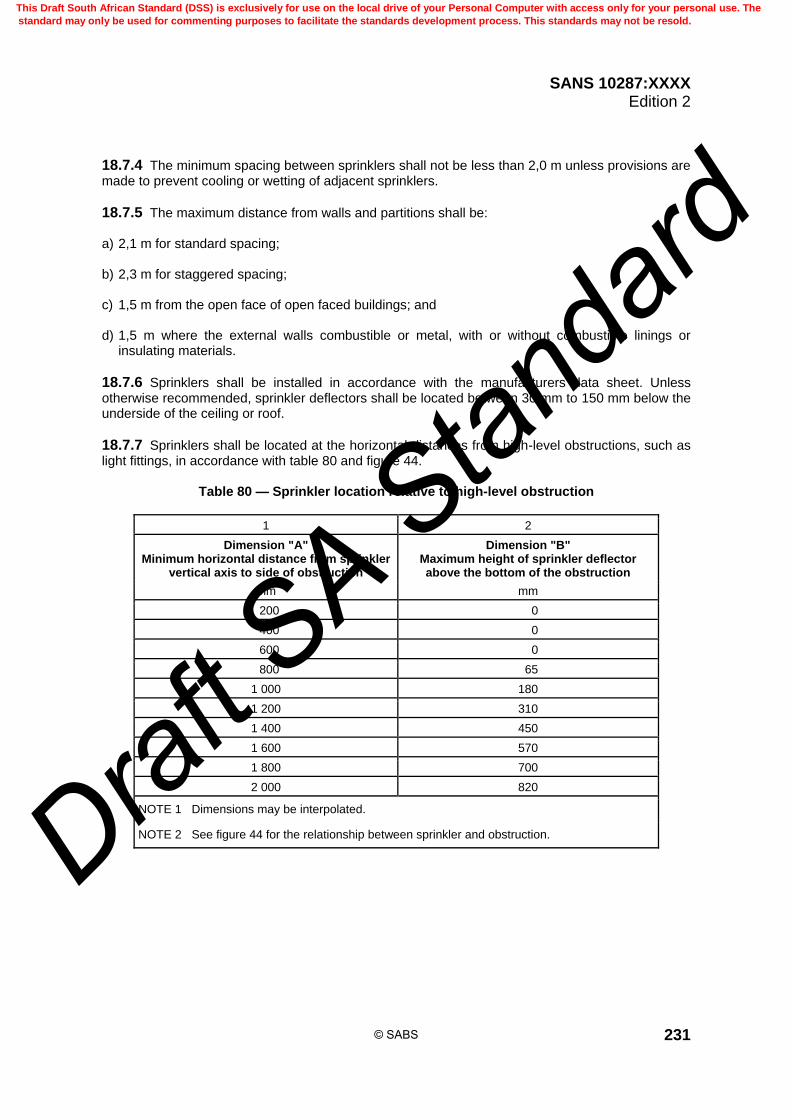
SANS 10287:XXXX Edition 2
231
18.7.4 The minimum spacing between sprinklers shall not be less than 2,0 m unless provisions are made to prevent cooling or wetting of adjacent sprinklers.
18.7.5 The maximum distance from walls and partitions shall be: a) 2,1 m for standard spacing; b) 2,3 m for staggered spacing; c) 1,5 m from the open face of open faced buildings; and d) 1,5 m where the external walls combustible or metal, with or without combustible linings or
insulating materials.
18.7.6 Sprinklers shall be installed in accordance with the manufacturers data sheet. Unless otherwise recommended, sprinkler deflectors shall be located between 30 mm to 150 mm below the underside of the ceiling or roof.
18.7.7 Sprinklers shall be located at the horizontal distances from high-level obstructions, such as light fittings, in accordance with table 80 and figure 44.
Table 80 — Sprinkler location relative to high-level obstruction
1 2
Dimension "A" Minimum horizontal distance from sprinkler
vertical axis to side of obstruction
Dimension "B" Maximum height of sprinkler deflector above the bottom of the obstruction
mm mm
200 0
400 0
600 0
800 65
1 000 180
1 200 310
1 400 450
1 600 570
1 800 700
2 000 820
NOTE 1 Dimensions may be interpolated.
NOTE 2 See figure 44 for the relationship between sprinkler and obstruction.
© SABS
This Draft South African Standard (DSS) is exclusively for use on the local drive of your Personal Computer with access only for your personal use. The
standard may only be used for commenting purposes to facilitate the standards development process. This standards may not be resold.
Draft S
A Stan
dard
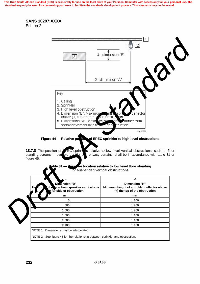
SANS 10287:XXXX Edition 2
232
Figure 44 — Relative position of EPEC sprinkler to high-level obstructions
18.7.8 The position of EPEC sprinklers relative to low level vertical obstructions, such as floor standing screens, moveable partitions or privacy curtains, shall be in accordance with table 81 or figure 45.
Table 81 — Sprinkler location relative to low level floor standing or suspended vertical obstructions
1 2
Dimension "D" Horizontal distance from sprinkler vertical axis
to far side of obstruction
Dimension "H" Minimum height of sprinkler deflector above
(+) the top of the obstruction
mm mm
0 1 100
500 1 700
1 000 1 700
1 500 1 100
2 000 1 100
2 100 1 100
NOTE 1 Dimensions may be interpolated.
NOTE 2 See figure 45 for the relationship between sprinkler and obstruction.
© SABS
This Draft South African Standard (DSS) is exclusively for use on the local drive of your Personal Computer with access only for your personal use. The
standard may only be used for commenting purposes to facilitate the standards development process. This standards may not be resold.
Draft S
A Stan
dard

SANS 10287:XXXX Edition 2
233
Figure 45 — Relationship between EPEC sprinkler and low level, floor standing or suspended vertical obstruction
18.8 Protection of concealed spaces in EPEC protected buildings
18.8.1 Concealed space sprinkler protection using EPEC sprinklers is allowed at extended coverage providing that specified criteria are met.
18.8.2 Where sprinkler protection is required in concealed ceiling or floor spaces in EPEC sprinkler protected buildings, the concealed space protection shall be installed in accordance with this standard using either standard sprinkler protection or EPEC sprinklers.
18.8.3 The space shall be sprinkler protected if the height of the concealed space at the roof, ceiling or floor exceeds 800 mm, measured between a) the underside of the roof and the top of the suspended ceiling, b) the floor slab and the suspended ceiling, and c) between the underside of the raised floor and the top of the floor slab.
18.8.4 If the height of the concealed space is less than 800 mm, the space shall be sprinkler protected only if it is constructed of combustible materials or contains combustible materials.
© SABS
This Draft South African Standard (DSS) is exclusively for use on the local drive of your Personal Computer with access only for your personal use. The
standard may only be used for commenting purposes to facilitate the standards development process. This standards may not be resold.
Draft S
A Stan
dard

SANS 10287:XXXX Edition 2
234
18.8.5 Electrical cables carrying less than 250 V, single-phase, with a maximum of 15 cables per tray are permitted in concealed spaces.
18.8.6 In concealed spaces where the surface above the sprinklers protecting the space does not exceed a slope of 9,5o, (170 mm in 1,0 m), the sprinklers may be installed at a maximum area per sprinkler of 17,64 m2.
18.8.7 Where the slope exceeds 9,5o, the maximum area per sprinkler shall not exceed 12 m2. The maximum distance between adjacent sprinklers shall not exceed 4,2 m.
18.8.8 The degree of obstruction in the concealed space shall also be considered when determining the spacing and positioning of sprinklers to protect the concealed space. In highly obstructed concealed spaces the maximum area coverage per sprinkler shall not exceed 12 m2.
18.8.9 Sprinklers used in concealed spaces shall be in accordance with table 82.
18.8.10 The pipework feeding sprinklers in concealed spaces shall be configured in accordance with this standard.
Table 82 — Sprinkler selection and design details
1 2 3 4 5
Sprinkler pattern
Nominal K-factor
Concealed space depth
Design density Minimum assumed maximum area of
operation
mm mm/min m2
Conventional upright
8,0 < 800 5,0 72
11,5 < 800 5,0 72
Conventional upright or pendent
8,0 ≥ 800 < 2 400 5,0 72
11,5 ≥ 800 < 2 400 5,0 72
Spray 8,0 ≥ 2 400 5,0 72
11,5 ≥ 2 400 5,0 72
Approved ceiling or roof void sprinklers
Use in accordance with suppliers data sheet indicated in the approval listing.
Use in accordance with suppliers data sheet indicated in the approval listing.
The supplier’s recommended value or 5,0 mm per minute, whichever is the greater
The minimum assumed maximum area of operation shall not be less than 72 m2 or the suppliers recommended value, whichever is the greater.
NOTE Upright sprinklers should be used where practicable. Upright sprinklers are usually more effective than pendent sprinklers where the height of the concealed space is restricted.
© SABS
This Draft South African Standard (DSS) is exclusively for use on the local drive of your Personal Computer with access only for your personal use. The
standard may only be used for commenting purposes to facilitate the standards development process. This standards may not be resold.
Draft S
A Stan
dard

SANS 10287:XXXX Edition 2
235
19 System components
19.1 Sprinklers
19.1.1 Sprinklers shall be of makes and types which are approved.
19.1.2 Sprinklers shall not be altered in any respect nor have any type of ornamentation, coating applied or be painted other than by the manufacturer after leaving the manufacturer’s facilities or except as provided in this standard.
19.1.3 Sprinklers shall not be screwed into range pipes before range pipe erection and may only be installed once the pipework is secured in place.
19.1.4 Only the manufacturer’s sprinkler wrench may be used to fit sprinklers to pipework.
19.1.5 Where it is necessary to screw sprinklers into prefabricated ranges at ground level, pipe racks shall be used, and the practice only undertaken immediately prior to hoisting the range into position.
19.1.6 Where sprinkler head protectors are used for shipping in order to prevent damage to the sprinklers, these shall remain in place and be removed when the sprinkler is in its intended installed position.
19.1.7 Sprinkler heads that have been in service may not be reused or relocated regardless of the circumstances. Once a sprinkler or a sprinkler pipe with sprinkler fitted to it is unscrewed from the fitting it shall be discarded.
19.1.8 The year of installation shall as far as possible correspond to that of manufacture.
19.1.9 Where a sprinkler is contaminated by paint or any other substance that adheres to any part of the sprinkler, it shall not be cleaned but shall be replaced with a new one.
19.1.10 Sprinklers shall be installed with the sprinkler frame running parallel to the pipe in order to avoid pipe or frame shadow.
19.1.11 Sprinkler heads shall not be intermixed. All sprinklers within any compartment at roof or ceiling level shall have identical operating characteristics inclusive of K-factor manufacturer, distribution patterns, orientation and thermal sensitivities. A compartment is defined as a room or area separated from any adjoining area with walls or partitions where a door lintel is at least 200 mm below the level of the sprinkler deflector.
19.1.12 On new installations and as far as is practicable for existing systems that are being extended, sprinkler equipment may not be intermixed.
19.1.13 Where rack or shelf sprinklers are installed the sprinkler, water shield and guard shall be supplied by the same manufacturer.
19.1.14 Spray pattern sprinklers with a K-factor greater than 11,5 may be used in high hazard installations only where the roof or ceiling insulation is classed as incombustible in accordance with relevant standards. In all other instances preference shall be given to conventional pattern sprinklers.
19.1.15 The operation of sprinklers operation is susceptible to side draughts which may be produced by roof ventilation, it is therefore preferable that roof ventilation be manually operated in the event of fire.
© SABS
This Draft South African Standard (DSS) is exclusively for use on the local drive of your Personal Computer with access only for your personal use. The
standard may only be used for commenting purposes to facilitate the standards development process. This standards may not be resold.
Draft S
A Stan
dard

SANS 10287:XXXX Edition 2
236
19.2 Type of sprinklers
19.2.1 General 19.2.1.1 In all cases the installation of a sprinkler shall be in accordance with the manufacturer’s requirements. 19.2.1.2 The types of sprinklers given in 19.2.2 to 19.2.17, but not necessarily limited to these, are accepted for use.
19.2.2 Conventional pattern 19.2.2.1 These sprinklers are designed to produce a spherical type of discharge with a proportion of water being thrown upwards to the ceiling. 19.2.2.2 They are usually designed with a universal type deflector, enabling the sprinkler to be erected in either the upright or pendant position. 19.2.2.3 Some conventional pattern sprinklers are made in two types, one suitable for erection in the upright position and the other in the pendent position. 19.2.2.4 Conventional pattern sprinklers shall be used a) to protect premises or portions thereof where there is exposed steelwork, and b) to provide optional protection of flat smooth concrete roofs or ceilings.
19.2.3 Spray pattern 19.2.3.1 These sprinklers are designed to produce a hemispherical discharge below the plane of the deflector with little or no water being discharged upwards to wet the ceiling. 19.2.3.2 They are made in two types, one suitable for erection in the upright position and the other in the pendent position. 19.2.3.3 Spray pattern sprinklers are to be used, if suitable, for the protection of a) rack and shelf in accordance with this standard, b) concrete beneath, coffer or smooth flat ceilings or roofs, and c) offices with under-drawn ceilings. 19.2.3.4 Fast response spray pattern sprinklers are used, for example, for the protection of life safety environments and intermediate level protection of racks and shelves. 19.2.3.5 Standard response spray pattern sprinklers may be used, for example, the protection of the underside of suspended ceilings and concrete construction where the premises do not comply with life safety.
19.2.4 Flat spray sprinklers A flat spray sprinkler produces a flatter spray pattern than a standard sprinkler, enabling them to be used with lower clearances above suspended open ceilings, the underside of mezzanine floors, in racks and within concealed spaces.
© SABS
This Draft South African Standard (DSS) is exclusively for use on the local drive of your Personal Computer with access only for your personal use. The
standard may only be used for commenting purposes to facilitate the standards development process. This standards may not be resold.
Draft S
A Stan
dard

SANS 10287:XXXX Edition 2
237
19.2.5 Ceiling (flush) pattern 19.2.5.1 The use of ceiling flush sprinklers for life safety applications such as hotels and offices is not acceptable as these are regarded as "double knock" operation. The cover plate shall fall away before the fusible element is exposed. In South Africa, the experience with this type of sprinkler is exceptionally poor in that they are either initially or eventually painted or plastered in thus rendering them useless. 19.2.5.2 Concealed sprinklers cannot be examined for correct installation or condition without removing the concealing plate assembly. These sprinklers take longer to respond to a fire due to their design and positioning of the fusible element relative to the fire gas flow. 19.2.5.3 These sprinklers are designed for use with concealed pipework and are installed pendent with a plate or base flush with the ceiling. The heat-sensitive element is positioned above the ceiling line. They are made with spray pattern discharge deflectors. 19.2.5.4 The following are the types of concealed sprinklers: a) those having fixed deflectors; b) those having retracted deflectors that drop to the normal position on actuation; and c) those having fusible cover plates. 19.2.5.5 Sprinklers of the type where the deflector drops to the normal operating position shall not
be fitted under stairs or sloping roofs where the angle of the stairs or roof exceeds 45 from the horizontal. 19.2.5.6 Ceiling flush pattern sprinklers are not considered suitable for use in atmospheres which are corrosive, subject to high dust content or rooms or areas subject to positive pressure.
19.2.6 Semi-concealed sprinklers 19.2.6.1 A sprinkler may be semi-concealed by using a recessed escutcheon plate. The escutcheon plate is fitted into the ceiling and rises slightly above it and the sprinkler is screwed into the fitting directly above the escutcheon plate. 19.2.6.2 These sprinklers are usually spray pattern type and are suitable for under-drawn or plastered ceilings where the pipework is concealed. 19.2.6.3 In all cases, no part of the escutcheon plate shall project from the ceiling below the top of the visible portion of the heat sensitive element of the sprinkler or that of the manufacturer’s requirement.
19.2.7 Sidewall pattern 19.2.7.1 These sprinklers are designed for installation in ordinary hazard occupancies only along the walls of a room close to the ceiling. 19.2.7.2 The design of the sprinkler is usually similar to the standard sprinkler except for a special deflector which causes most of the water to be discharged to one side in a pattern somewhat resembling one quarter of a sphere with a small proportion discharging on the wall behind the sprinkler. 19.2.7.3 Sidewall pattern sprinklers are not considered a substitute for standard sprinklers and their use is, in the main, limited to offices, entrance halls, lobbies, corridors, etc.
© SABS
This Draft South African Standard (DSS) is exclusively for use on the local drive of your Personal Computer with access only for your personal use. The
standard may only be used for commenting purposes to facilitate the standards development process. This standards may not be resold.
Draft S
A Stan
dard

SANS 10287:XXXX Edition 2
238
19.2.7.4 Sidewall sprinklers can, however, be used in the case of drying tunnels and hoods over paper-making machines where condensate dripping from sprinklers and pipework at the ceiling might be troublesome. They can also be used in certain other locations such as sales shop windows and under platforms, etc., having low headroom, where standard sprinklers would be subject to damage. 19.2.7.5 Sidewall sprinklers may also be used for the protection of corridors in high hazard occupancies where no storage takes place, cable ducts and for the protection of columns and structural members in high hazard storage facilities. 19.2.7.6 Sidewall sprinklers shall not be used in high hazard or ordinary hazard storage occupancies or above suspended ceilings for general protection purposes.
19.2.8 Extended coverage horizontal sidewall 19.2.8.1 These sprinklers are designed for use within ordinary hazard occupancies excluding storage risks and have coverage greater than a standard sidewall sprinkler. 19.2.8.2 Their use is limited to low fire loading life safety environments such as offices and hotel rooms where the room length cannot be adequately covered by normal sidewall sprinklers and the installation of standard sprinkler protection is not possible. 19.2.8.3 The distances from the ceiling or roof are critical and in all cases the manufacturer’s requirements shall be adhered to. 19.2.8.4 Care shall be taken in the decision of where to use these sprinklers as the nominal thread diameter varies.
19.2.9 Extended coverage 19.2.9.1 Extended coverage sprinklers are normally of the spray pattern type and are suitable for ordinary hazard risks where extended spacing can be advantageous such as open office areas, retail areas or shopping malls. 19.2.9.2 In all cases the manufacturer’s specifications with respect to the spacing of the sprinklers and the flows and pressures at the predetermined spacing shall be adhered to.
19.2.10 Enhanced protection extended coverage 19.2.10.1 EPEC sprinkler protection is specialised and are used specifically for storage of commodities that have undergone fire tests and for ordinary hazard occupancies. 19.2.10.2 The protection is to be installed in accordance with the requirements of this standard.
19.2.11 Early suppression fast response (ESFR) sprinklers 19.2.11.1 Early suppression fast response, sprinklers are thermo-sensitive devices designed to react at a predetermined temperature by automatically releasing a stream of water and distributing it in a specified pattern and density over a designated area to provide early suppression of a fire when installed on the appropriate sprinkler piping with a suitable water supply. 19.2.11.2 ESFR sprinklers are quick-acting high-performance sprinklers which have the capability of suppressing fires within storage risks.
© SABS
This Draft South African Standard (DSS) is exclusively for use on the local drive of your Personal Computer with access only for your personal use. The
standard may only be used for commenting purposes to facilitate the standards development process. This standards may not be resold.
Draft S
A Stan
dard

SANS 10287:XXXX Edition 2
239
19.2.11.3 Errors in the design and installation of ESFR sprinkler systems are not acceptable. The design principles and the operating characteristics of the ESFR sprinkler systems are significantly different from standard sprinkler protection. 19.2.11.4 ESFR sprinklers may be unable to cope with adverse design features and non-compliance. It is therefore essential that all the requirements of this standard are complied with when applying ESFR protection.
19.2.12 Dry pendent pattern 19.2.12.1 These sprinklers are for use in portions of premises protected by a dry pipe or an alternate wet and dry pipe system where it is not practicable to install standard sprinklers in the upright position or on a wet pipe system where the sprinklers may be subject to frost or freezing such as cold rooms or exposed portions of a building. 19.2.12.2 Apart from the valve arrangement, the sprinklers are of standard design having either conventional or pendent spray pattern type deflectors. 19.2.12.3 Dry pendent pattern droppers are manufactured integral with drop pipes of varying lengths, the valve being so placed that there is no pocket or depression within which water can be trapped. 19.2.12.4 Dry pendent droppers may not be screwed directly into elbows; in all cases tees shall be used.
19.2.13 Dry upright pattern 19.2.13.1 These sprinklers are the same as the dry pendent types except that instead of the spray pattern, an upright type deflector is incorporated. 19.2.13.2 Dry upright pendent pattern are used for the protection of unheated concealed roof spaces in connection with installations on the wet pipe system.
19.2.14 Intermediate level or in-rack sprinkler 19.2.14.1 A sprinkler that is primarily designed for use within in-rack storage and fitted with a water shield which is approved where the operating element or parts close to this shall be shielded from the water discharged from sprinklers at a higher elevation. 19.2.14.2 They may also be used under gratings, on pilot sprinklers for deluge systems, outdoors as a weather shield or any other application where water shielding is required. 19.2.14.3 The sprinkler shall be approved with a water shield as an intermediate level/rack sprinkler.
19.2.15 Medium velocity and high velocity sprayers 19.2.15.1 These are special purpose sprayers that produce a downward conical spray pattern directional onto the risk for use in water spray systems, (which may or may not form part of standard sprinkler systems), intended for the extinguishment or control of fires involving flammable liquids and for the cooling of storage tanks, process plant and exposed structural steelwork against heat from an exposure to fire. 19.2.15.2 Medium velocity spray systems are not recommended to be used for the protection of transformers. It is recommended to emulsify the oil used for cooling purposes and for this purpose high velocity spray systems will be required.
© SABS
This Draft South African Standard (DSS) is exclusively for use on the local drive of your Personal Computer with access only for your personal use. The
standard may only be used for commenting purposes to facilitate the standards development process. This standards may not be resold.
Draft S
A Stan
dard

SANS 10287:XXXX Edition 2
240
19.2.15.3 Where medium or high velocity spray systems are fed from a separate set of valves or tail end system, the requirements of NFPA 15 shall be used. 19.2.15.4 These sprayers have directional discharge characteristics with cone angles ranging from
40 to 180 and with orifice sizes varying from 5 mm to 13 mm. 19.2.15.5 The medium velocity sprayers are produced as either a) sealed sprayers with glass bulbs or soldered links or levers as for standard sprinklers, or b) open sprayers. 19.2.15.6 Medium velocity sprayers are designed for cooling purposes when dealing with fires involving low flash point fire hazards as, for example, liquefied petroleum gases. 19.2.15.7 In such risks the aim is not for automatic extinguishment, but to control the burning within safe limits until the source of gas supply has been shut off, thus avoiding the danger following a fire incident of these heavier-than-air gases continuing to escape and collecting in low lying areas producing an explosion hazard. 19.2.15.8 The high velocity sprayers are of the open type and are designed for the extinguishment of fires involving high flash point liquids.
19.2.16 Multiple-jet-controls 19.2.16.1 These are heat-sensitive sealed valve controlled outlets, (single or double), using either glass bulbs or soldered links or levers as the heat sensitive device. They are for use in systems using medium or high velocity sprayers of the open type in circumstances where it is required to operate small groups of sprayers simultaneously. 19.2.16.2 The controls are made in various sizes relevant to the diameter of the valve and the number of sprayers that are to be fed therefrom. 19.2.16.3 Typically multiple-jet-controls are used for the protection of small flammable liquid stores and standby generators. 19.2.16.4 Multiple-jet-controls have sliding valve components and are susceptible to build-up of corrosion, paint and environmental deposits which may render the device unserviceable or slow to operate. 19.2.16.5 Depending on the installed conditions and service life, these need to be examined on a regular basis and, if necessary, overhauled or replaced.
19.2.17 Sprinklers with a 15 mm shank threads and K-factors of 11,5 Sprinklers with a 15 mm shank thread and a K-factor of 11,5 shall only be used in refit applications. Replacing 15 mm sprinklers (K-factor of 8,0) is allowable in installations where the suitability of the water supplies, pipework and enlarged sprinkler head orifice has been proven and remains within the maximum allowable parameters of the requirements for full hydraulic calculation.
19.2.18 Recessed, horizontal sidewall and concealed heads 19.2.18.1 Recessed, horizontal sidewall and concealed heads are not designated with a thermal sensitivity rating.
© SABS
This Draft South African Standard (DSS) is exclusively for use on the local drive of your Personal Computer with access only for your personal use. The
standard may only be used for commenting purposes to facilitate the standards development process. This standards may not be resold.
Draft S
A Stan
dard

SANS 10287:XXXX Edition 2
241
19.2.18.2 The standard thermal sensitivity test is not appropriate and these are classified as unrated due to at least one of the following reasons: a) the nature of the sprinkler assembly; b) orientation of the sprinkler frame when installed; c) location of the temperature-sensitive element in relation to the roof or ceiling line; and d) sprinklers with protective coatings over the heat-sensitive element. 19.2.18.3 The temperature-sensitive elements and their supporting components used in the construction of these sprinklers shall operate in accordance with the special or quick response requirements when tested on a conventional spray or sidewall pattern sprinkler frame or suitable mounting assembly.
19.3 Sprinkler orifice sizes
19.3.1 Sprinklers having the nominal sizes in column 1 of table 83 are approved for the respective hazard classes given in column 2.
Table 83 — Conventional pattern sprinkler nominal pipe thread diameters
1 2
Nominal size Hazard class
mm
15 Ordinary and high hazard
20 High hazard only
25 High hazard only
19.3.2 To avoid the possibility of inadvertent interchange between sprinklers of different orifice sizes, table 84 shows the general relationship that shall exist between sprinkler nominal thread size and nominal orifice size.
19.3.3 Unless allowed for in this standard, sprinklers of differing types, operating temperature, response times, fusible bulb diameters or distribution patterns may not be intermixed.
19.3.4 The same manufacturer’s equipment shall be used for new installations and extensions to existing systems, i.e. control valves, sprinkler heads, flow switches, detection, etc. as far as practical.
19.3.5 Sprinklers shall be marked on the body or the deflector with an indication of nominal orifice size, type of distribution pattern, approving authority and sprinkler identification number.
© SABS
This Draft South African Standard (DSS) is exclusively for use on the local drive of your Personal Computer with access only for your personal use. The
standard may only be used for commenting purposes to facilitate the standards development process. This standards may not be resold.
Draft S
A Stan
dard
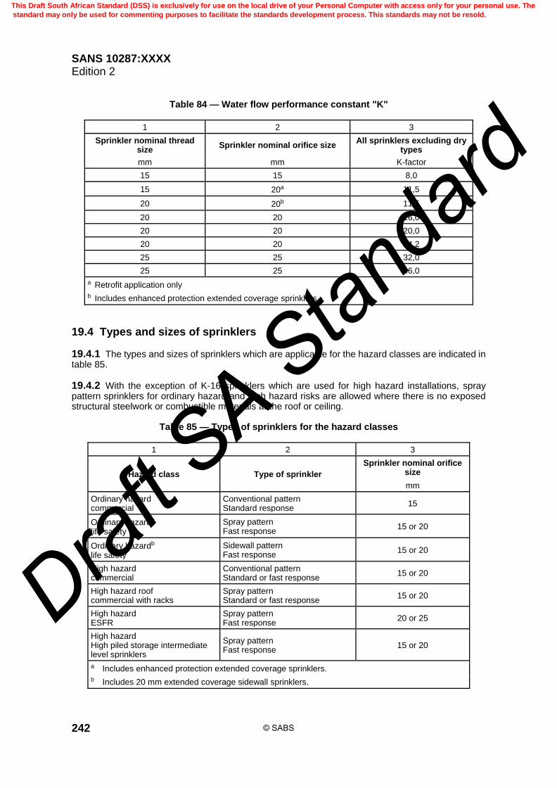
SANS 10287:XXXX Edition 2
242
Table 84 — Water flow performance constant "K"
1 2 3
Sprinkler nominal thread size
Sprinkler nominal orifice size All sprinklers excluding dry
types
mm mm K-factor
15 15 8,0
15 20a 11,5
20 20b 11,5
20 20 16,0
20 20 20,0
20 20 24,2
25 25 32,0
25 25 36,0
a Retrofit application only
b Includes enhanced protection extended coverage sprinklers
19.4 Types and sizes of sprinklers
19.4.1 The types and sizes of sprinklers which are applicable for the hazard classes are indicated in table 85.
19.4.2 With the exception of K-16 sprinklers which are used for high hazard installations, spray pattern sprinklers for ordinary hazard and high hazard risks are allowed where there is no exposed structural steelwork or combustible materials at the roof or ceiling.
Table 85 — Types of sprinklers for the hazard classes
1 2 3
Hazard class Type of sprinkler
Sprinkler nominal orifice size
mm
Ordinary hazard commercial
Conventional pattern Standard response
15
Ordinary hazarda life safety
Spray pattern Fast response
15 or 20
Ordinary hazardb life safety
Sidewall pattern Fast response
15 or 20
High hazard commercial
Conventional pattern Standard or fast response
15 or 20
High hazard roof commercial with racks
Spray pattern Standard or fast response
15 or 20
High hazard ESFR
Spray pattern Fast response
20 or 25
High hazard High piled storage intermediate level sprinklers
Spray pattern Fast response
15 or 20
a Includes enhanced protection extended coverage sprinklers.
b Includes 20 mm extended coverage sidewall sprinklers.
© SABS
This Draft South African Standard (DSS) is exclusively for use on the local drive of your Personal Computer with access only for your personal use. The
standard may only be used for commenting purposes to facilitate the standards development process. This standards may not be resold.
Draft S
A Stan
dard
SANS 10287:XXXX Edition 2
243
19.5 Temperature rating
19.5.1 Sprinklers are approved in nominal temperature ratings ranging from 57 °C to 260 °C.
19.5.2 The temperature rating chosen shall be as close as possible to, but not less than, 30 °C above the highest anticipated temperature conditions.
19.5.3 For conditions in Southern Africa, a rating of 68 °C or 79 °C is generally suitable for ordinary hazard occupancies.
19.5.4 Under glazing and in unventilated concealed spaces which includes ceiling or roof voids and show windows, it will be necessary to install sprinklers with a temperature rating between 93 °C and 141 °C.
19.5.5 In Ordinary Hazard systems installed within cold rooms and freezers where the temperature
is maintained below 5 C, 68 C operating temperature fast response sprinklers with an RTI of less than 50 shall be used.
19.5.6 In High Hazard systems, installed within cold rooms and freezers where the temperature is
maintained below 5 C, 93 C operating temperature fast response sprinklers with an RTI of less than 50 shall be used at roof or ceiling level whether the risk protected is process or protection over racks.
19.5.7 Unless otherwise stipulated, in high hazard systems, 93 °C sprinklers shall be used on all high hazard risks whether they are process or roof protection over racks.
19.5.8 Where high temperature sprinklers are installed within, for example, drying ovens or hoods over paper-making machines, sprinklers at the ceiling or roof immediately over and to a distance of 3,0 m beyond the boundary of such structures shall be of the same temperature rating, subject to a
maximum of 141 C.
19.5.9 In all cases where sprinklers are installed in buildings having PVC, GRP, polycarbonate or similar translucent roof lights, sprinkler heads shall not be installed directly below such roof lights. The sprinkler spacing requirements of this standard shall, however, be observed.
19.5.10 If sprinklers are positioned beneath roof lights, these shall be flush to the ceiling or under drawn at ceiling level. Roof lights shall be capable of withstanding a temperature of 300 °C for a period of not less than 5 min.
19.5.11 In all cases in high hazard risks and where sprinklers having temperature ratings exceeding 68 °C are installed in ordinary hazard risks, the use of PVC roof light or similar material above the sprinklers shall be as follows a) the area of each roof light shall not exceed 5 m2, b) the distance between individual roof lights shall not be less than 1,8 m, and c) the total area of such roof lights does not exceed 15 % of the plan area of the buildings.
19.5.12 Tables 86 and 87 provides the colour codes to distinguish sprinklers of different nominal temperature ratings.
© SABS
This Draft South African Standard (DSS) is exclusively for use on the local drive of your Personal Computer with access only for your personal use. The
standard may only be used for commenting purposes to facilitate the standards development process. This standards may not be resold.
Draft S
A Stan
dard

SANS 10287:XXXX Edition 2
244
Table 86 — Yoke arm colour codes
1 2
Soldered and fusible chemical type Colour of yoke arms
°C
68 and 74 Uncoloured
93 and 100 White
141 Blue
182 Yellow
227 Red
Table 87 — Fusible bulb colour codes
1 2
Glass bulb types Colour of bulbs
°C
57 Orange
68 Red
79 Yellow
93 Green
141 Blue
182 Mauve
204 and 260 Black
19.5.13 The choice of the sprinkler head at roof or ceiling level is critical in ensuring that the optimal design density of discharge is achieved.
19.5.14 Sprinklers spaced to maximum coverage are less effective in controlling a fire than when spacing is reduced due to the higher pressures required in order to achieve the density of discharge.
19.5.15 The higher the pressure the smaller and less efficient the droplet will be and the greater the likelihood of a larger number of sprinklers operating for the control of a fire will be. Preference should be given to a low pressure system.
19.5.16 Table 88 defines the minimum K-factor of sprinkler to be used for specific design densities of discharge.
Table 88 — Sprinkler K-factor against design density of discharge
1 2 3
Category of risk
Design density K-Factor
mm per minute per m2
Metric
Ordinary hazard 5,0 K-8,0
High hazard ≥ 7,5 ≤ 10,0 K-8,0 or K-11,5
High hazard ≥ 12,5 ≤ 17,5 K-11,5 or K-16,0
High hazard > 17,5 K-16,0
© SABS
This Draft South African Standard (DSS) is exclusively for use on the local drive of your Personal Computer with access only for your personal use. The
standard may only be used for commenting purposes to facilitate the standards development process. This standards may not be resold.
Draft S
A Stan
dard

SANS 10287:XXXX Edition 2
245
19.5.17 Where spray pattern sprinklers, K-16,0, are used for the protection of a risk under exposed steel construction, it shall be ensured that the roof level insulation is non-combustible and that the supplementary protection is provided for the steel supports.
19.6 Stock of replacement sprinklers
19.6.1 A stock of spare sprinklers shall be maintained on the premises so that any sprinklers that have been operated or have been damaged in any way may be promptly replaced.
19.6.2 Spare sprinklers shall be kept in cabinets located in a central prominent and easily accessible position where ambient temperature conditions will not exceed 38 °C.
19.6.3 Spare sprinklers suitably sized pipe plugs can be kept within the spares cabinet and the additional stock of replacement sprinklers can be kept within a remote secure area.
19.6.4 The correct sprinkler spanners as provided by the manufacturer shall be kept within the spares box as well as any pipe wrench that may be required in order to remove any sprinkler of the types installed and replace these or plug off the outlet.
19.6.5 The number of spare sprinklers to be maintained on the premises will largely depend on the size of the protected premises and the hazard class of the system.
19.6.6 The minimum number of spare sprinklers and plugs shall be maintained of standard temperature ratings used for the installation under consideration (see table 89).
Table 89 — Stock of replacement sprinklers
1 2
Hazard Number of spares and plugs
Ordinary hazard systems 24
High hazard systems 36
ESFR and special Assumed maximum number of sprinklers in operation
19.6.7 Where there is more than one installation, the stock of replacement sprinklers and plugs shall be increased by 50 %.
19.6.8 Should the systems include sprinklers of higher temperature ratings as, for example, in boiler rooms or drying ovens an adequate number of spare sprinklers of the appropriate temperature rating shall be maintained.
19.6.9 Similarly, if the systems include differing or special types of sprinklers or if there are any multiple-jet-controls, an adequate number of these spares shall be maintained.
19.6.10 The sprinkler installer(s) shall be requested, immediately after an incident, to replenish the spares. Their advice shall be sought regarding the possible necessity of replacing sprinklers on the perimeter of the area, which may not have actually operated, but which might have been affected by the fire.
© SABS
This Draft South African Standard (DSS) is exclusively for use on the local drive of your Personal Computer with access only for your personal use. The
standard may only be used for commenting purposes to facilitate the standards development process. This standards may not be resold.
Draft S
A Stan
dard

SANS 10287:XXXX Edition 2
246
19.7 Anti-corrosion treatment of sprinklers
19.7.1 Sprinklers used in bleach, dye and textile print works, alkali plants, organic fertiliser plants, foundries, pickle and vinegar works, electro plating and galvanizing works, paper mills, tanneries, and in any other premises or portions of premises where corrosive vapours are prevalent, shall have corrosion resistant coating which is approved (applied by the manufacturer) or shall be coated twice with a good quality petroleum jelly, the first coat to be applied before erection and the second after installation.
19.7.2 The petroleum jelly coatings are to be renewed at periodic intervals as may be necessary, but only after the existing coatings have been thoroughly wiped off.
19.7.3 In the case of glass bulb type sprinklers, the anti-corrosion treatment need only be applied to the body and yoke.
19.8 Sprinkler guards In situations where sprinklers are liable to accidental or mechanical damage, for example, cold rooms, freezers, the underside of mezzanine floors, intermediate rack or shelf protection or sprinklers protecting low structures, sprinklers shall be protected by fitting metal guards which are approved as provided by the manufacturer of the sprinkler heads.
19.9 Escutcheon plates
19.9.1 Escutcheon plates or rosettes are plates that cover the gap between the shank or body of a sprinkler projecting through a suspended ceiling and the ceiling.
19.9.2 Where installed, these shall be manufactured from either metal or thermosetting plastic material.
19.9.3 The escutcheon plate shall not be used to support ceilings or other structures. No part of the escutcheon plate may protrude beyond the top of the visible portion of the sprinkler heat sensitive element.
19.9.4 Escutcheon plates used with recessed, semi recessed or flush type sprinklers shall be part of the sprinkler assembly which is approved.
19.9.5 Cover plates used with concealed sprinklers shall be part of the sprinkler assembly which is approved.
20 Pipework
20.1 General care of materials and protection of pipework
20.1.1 Sprinkler pipework shall be suitably rated in terms of the maximum working pressure of a sprinkler system.
20.1.2 Sprinkler pipework that has been in service may not be reused and shall be discarded if stripped out from its original location.
20.1.3 All sprinkler pipework concealed or exposed either above ground or in-ground shall be suitably cleaned, primed and painted with a finished coat in accordance with SANS 10140-3.
20.1.4 Components shall be properly stored on site until they are required for installation.
© SABS
This Draft South African Standard (DSS) is exclusively for use on the local drive of your Personal Computer with access only for your personal use. The
standard may only be used for commenting purposes to facilitate the standards development process. This standards may not be resold.
Draft S
A Stan
dard
SANS 10287:XXXX Edition 2
247
20.1.5 The unloading stacking and storage of components shall be carried out with care to prevent damage to pipe and pipe threads, valves and sprinklers, gauges and any pump and power units used in the installation.
20.1.6 Components shall be so stored that they are not damaged by building operations. Site locations shall be prepared in advance of delivery so that heavy items, such as fire pumps and strainers can be transported direct to their final locations.
20.1.7 Pipes shall be protected, for example, by caps against the entry of foreign matter, such as rubble and cordage, and shall be examined for such matter before erection.
20.1.8 The open ends of pipes shall be capped as building construction proceeds.
20.1.9 Pipes shall be protected from the effects of the vehicular traffic and shall not be located where they are liable to be damaged by forklift trucks or mobile equipment.
20.1.10 Pipes above gangways that are not situated above the maximum equipment height shall be fitted with guards which are approved as shall sprinkler pipework beneath mezzanine floors, racks or under shelves.
20.1.11 Where possible the pipes shall be so located as to be protected from mechanical damage.
20.1.12 If mobile equipment is used, guard rails shall be provided and safety guidelines shall be marked on the floor around pipe risers.
20.1.13 Water supply pipework in the non-sprinkler protected buildings shall be installed at the ground level and enclosed by fire rated dwarf walls covered by concrete slabs.
20.1.14 Sprinkler supply pipework shall not be routed to a sprinkler protected building either through a building that is not sprinkler protected or externally above ground unless the pipe is enclosed within a fire rated enclosure.
20.1.15 Sprinkler pipework shall not be run in the open or within an unprotected building and provide sprinkler protection above the pipe.
20.1.16 Trunk mains to installations that protect buildings with hazardous processes or explosion hazards (or both) shall either be outside the building or shall be protected against possible damage owing to collapse of the building.
20.1.17 Sprinkler pipework shall not be chased into the walls or embedded in the concrete floor or ceiling of the building.
20.1.18 Sprinkler pipes shall not be concealed in any situation where this would result in difficulty or undue expense when the installation is to be modified or expanded.
20.1.19 Underground piping shall be set at a depth that is sufficient to prevent the water they contain from freezing and from the effects of vehicular traffic. A minimum depth of 900 mm below finished ground level is usually deemed to be acceptable. All underground pipe shall be suitably protected and laid on a bed of washed river sand of not less than 250 mm depth and covered to at least 250 mm above the top of any flange or fitting with washed river sand.
20.1.20 the installation of underground pipework thrust and anchor blocks shall be in accordance with the manufacturer's requirements and recommendations. The calculation of thrust and anchor blocks is complex whereby soil types and compaction criteria are critical to the overall mass requirements.
© SABS
This Draft South African Standard (DSS) is exclusively for use on the local drive of your Personal Computer with access only for your personal use. The
standard may only be used for commenting purposes to facilitate the standards development process. This standards may not be resold.
Draft S
A Stan
dard

SANS 10287:XXXX Edition 2
248
20.2 Pipework that feeds sprinklers and sprayers
20.2.1 Individual sprinklers shall not be connected direct to distribution pipes. These are connected using an arm pipe which is a pipe other than the last section of a range pipe that feeds a single sprinkler.
20.2.2 Arm pipes or drop pipes of nominal diameter not exceeding 32 mm shall be used to connect individual sprinklers where these are fed from pipes of nominal diameter exceeding 65 mm.
20.2.3 In the case of range pipes and terminal distribution pipes in ordinary hazard installations, any single sprinkler shall be fed by pipework of nominal diameter at least 25 mm.
20.2.4 The nominal diameter of range pipes shall not be less than 25 mm.
20.2.5 Except where allowed in this standard such as in the case of ESFR sprinkler protection, the nominal diameter of range pipes shall not exceed 65 mm, except where individual sprinklers are connected to pipes of nominal diameter exceeding 65 mm, when the array shall comply with this standard.
20.2.6 Any common main feed or distribution pipe shall be of nominal diameter of at least 65 mm.
20.2.7 Gridded systems shall be of a uniform pipe diameter. Ranges and mains shall be uniform and shall not increase or decrease in diameter.
20.3 Pipework that feeds upright or pendent conventional pattern or spray sprinklers
20.3.1 If upright or pendent conventional or spray sprinklers are installed within 400 mm of the pipe axis alongside a pipe of nominal diameter exceeding 65 mm, the deflector shall be not more than the appropriate distance given in table 90 above the lower edge of the pipe.
20.3.2 If a sprinkler is fitted in a drop from a pipe of nominal diameter exceeding 65 mm, the horizontal centre line of the exposed portion of the sprinkler detector element shall be at least 75 mm below the lower edge of the pipe.
20.3.3 The vertical centre line of detection elements of sidewall sprinklers that are fed from the side of and that spray away from a pipe of nominal diameter exceeding 65 mm shall be situated at least 75 mm distance from the side of the pipe.
Table 90 — Location of sprinklers alongside feed pipes exceeding 65 mm
1 2 3
Minimum horizontal distance from pipe centre
line to sprinkler centre line Maximum height of sprinkler deflector above lower edge of pipe
mm
Conventional sprinkler installed upright
Spray sprinkler, (upright and pendent) and pendent conventional sprinkler mm
100 0 17
200 17 40
400 34 100
NOTE Dimensions can be interpolated.
© SABS
This Draft South African Standard (DSS) is exclusively for use on the local drive of your Personal Computer with access only for your personal use. The
standard may only be used for commenting purposes to facilitate the standards development process. This standards may not be resold.
Draft S
A Stan
dard

SANS 10287:XXXX Edition 2
249
20.4 Pipes and sprinkler fittings
20.4.1 Pipes and sprinkler fittings shall be suitable for sprinkler use.
20.4.2 The following pipes fittings are deemed suitable for sprinkler use (depending on the application): a) steel pipes that comply with SANS 62-1; b) steel pipes, large bore that comply with SANS 719; c) fabricated flanged steel pipes and fittings used upstream of the alarm valve above ground and that
comply with the requirements of SANS 1476; d) shouldered-end pipes, fittings and couplings that comply with the requirements of SANS 815-1 and
SANS 815-2, and specifically approved for sprinkler use; e) malleable cast iron pipe fittings that comply with the requirements of SANS 14; f) cast iron fittings for fibre-cement pressure pipes that comply with the requirements of SANS 1223; g) cast iron fittings and couplings for shouldered-end pipes that comply with the requirements of
SANS 815-1 and SANS 815-2; h) fibre-cement pressure pipes that comply with the requirements of SANS 1223; i) polypropylene pressure pipes and fittings installed below ground; j) pre-stressed concrete pressure pipes that comply with the requirements of SANS 975; k) reinforced concrete pressure pipes that comply with the requirements of SANS 676; and l) class 16 pipe and components of PVC-U pressure pipe systems that comply with the requirements
of SANS 966-1 or SANS 966-2.
20.4.3 Black polyethylene pipe (HDPE) is not deemed suitable for sprinkler use.
20.4.4 One piece reducing fittings shall be used where a change in the size of the pipe is made. Hexagonal or face bushings shall be permitted in reducing the size of openings of fittings only when standard fittings of the required size are not available.
20.4.5 Galvanized pipe shall be used for dry pipe systems and shall be used for the downstream pipework of any test or drain valve installed on the system. Shouldered or grooved couplings are not suitable for use in dry pipe systems. Fittings for dry pipe systems shall be flanged or screwed.
20.4.6 Galvanized pipe shall not be used for systems where foam is introduced.
20.4.7 Where possible and practical the socket or connection for a distribution or feed pipe, sprinkler ranges or return bends (swivel arrangements) shall be taken from the top or side of the pipe feeding in order to avoid the accumulation or deposit of sediment within the pipe.
© SABS
This Draft South African Standard (DSS) is exclusively for use on the local drive of your Personal Computer with access only for your personal use. The
standard may only be used for commenting purposes to facilitate the standards development process. This standards may not be resold.
Draft S
A Stan
dard

SANS 10287:XXXX Edition 2
250
20.5 CPVC plastic pipe
20.5.1 The term "CPVC pipe" refers to both CPVC plastic pipe and CPVC plastic pipe fittings. CPVC requirements in this standard shall be read in conjunction with the supplier’s installation requirements.
20.5.2 If the occupancy under consideration is not suitable for protection as defined within this standard, CPVC pipe may not be used.
20.5.3 Where the system is designated as life safety, careful consideration of the use of CPVC pipe is required.
20.5.4 Sprinkler heads installed with CPVC pipe shall have a temperature rating not exceeding 79 °C.
20.5.5 CPVC pipe can be used only in occupancies classed as ordinary hazard which include or are similar to hotels, hospitals (excluding kitchens and plant rooms) museums, libraries, (excluding stock rooms), court rooms, nursing homes, offices and data processing rooms, schools colleges, prisons, churches, restaurant seating areas, theatres and auditoriums (excluding stages and prosceniums), unused attics and retail sales areas.
20.5.6 Where used in retail sales areas, the storage type is limited to ordinary hazard free standing or block storage of category I goods. Only concealed pipework shall be used for the protection of storage areas, exposed pipework may not be used.
20.5.7 CPVC pipe may only be used in wet pipe systems. CPVC shall not be used in dry pipe, alternate, pre-action or recycling systems. Consideration shall be given to the use of gridded or looped systems such that the operation of a single sprinkler exposes the pipework to flow which will assist in added cooling to the pipe.
20.5.8 CPVC pipework shall only be installed downstream of the installation alarm valve. The maximum nominal bore of pipework shall not exceed 80 mm for distribution pipes and 65 mm for range pipes.
20.5.9 CPVC pipe shall not be installed or used outdoors or in locations that are exposed to UV radiation. Paint or lagging (or both) that is approved by the pipe manufacturer can be used to protect CPVC pipe indoors from UV radiation.
20.5.10 CPVC pipe shall only be used where the expected ambient temperature is in the range from −2 °C to 50 °C.
20.5.11 Where CPVC pipe is used in corrosive conditions, the pipe and fittings shall be tested and approved for use in such areas or conditions.
20.5.12 The installation of CPVC pipe shall be carried out in accordance with the suppliers’ guidelines or design manual (or both) and recommendations of a competent person.
20.5.13 Following installation joints shall be left to cure for the appropriate minimum periods as given by the suppliers’ installation instructions. Particular care shall be taken that the correct curing times for cementing of CPVC pipes are maintained. The pipe size, tightness of fit, temperature and relative humidity, all influence the set and cure times. Drying time is faster for smaller pipes, tighter fits, higher temperatures and drier environments.
20.5.14 Sprinkler heads shall not be installed until after the correct curing time has elapsed.
© SABS
This Draft South African Standard (DSS) is exclusively for use on the local drive of your Personal Computer with access only for your personal use. The
standard may only be used for commenting purposes to facilitate the standards development process. This standards may not be resold.
Draft S
A Stan
dard

SANS 10287:XXXX Edition 2
251
20.5.15 Only PTFE tape, paste or other substances which have been tested and approved by the supplier shall be used when making threaded joints.
20.5.16 CPVC installations shall be pressure tested to 1 500 kPa or 1,5 times the maximum working pressure, whichever is the greater for a period of not less than 2 h. Only water shall be used for pressure testing of pipework. CPVC piping systems are not designed for use of compressed gas, including air and these shall not be used. Any fault disclosed, such as permanent distortion, rupture or leakage shall be corrected and the test repeated.
20.6 CPVC-exposed pipework
20.6.1 Where CPVC pipe is exposed, the following shall be met: a) sprinkler heads shall be rated as fast response with an RTI of less than 50; b) sprinkler pipework shall be installed beneath smooth, flat horizontal ceilings; c) pendent sprinklers shall be installed with their deflectors not more than 150 mm below the ceiling
at centres not exceeding 4,0 m; d) upright sprinklers shall be installed with their deflectors not more than 100 mm below the ceiling at
centres not exceeding 4,0 m; and e) sidewall sprinklers shall be installed with their deflectors not more than 150 mm below the ceiling
and 100 mm from the wall.
20.6.2 Protection above an open cell, or open grid ceiling, shall comply with the requirements in 20.6 for exposed pipework as well as the requirements for suspended open ceilings as detailed in this standard (see 16.9).
20.6.3 The maximum system working pressure under flowing conditions shall not exceed 690 kPa or in accordance with the manufacturer’s recommendations.
20.7 Flexible connectors
20.7.1 Flexible connectors which are approved suitable for sprinkler service only are acceptable and shall comply with the following requirements given in 20.7.2 to 20.7.15, and as shown in figure 46 and figure 47.
20.7.2 Flexible connectors which are approved shall comply with the supplier’s instructions and shall not exceed any limitations of use stated in their certification listing.
20.7.3 These may be used on wet pipe installations only.
20.7.4 The total aggregate bend shall not exceed the value stated in the product certification listing.
20.7.5 All flexible connector sprinkler terminations shall be supported by the product supplier’s certificated support bracket assembly.
20.7.6 The flexible connection shall be of the appropriate length.
20.7.7 Pipe bending to reduce the effective flexible connector length is not permissible.
20.7.8 Flexible connectors can only be used to connect a single sprinkler to a distribution pipe.
© SABS
This Draft South African Standard (DSS) is exclusively for use on the local drive of your Personal Computer with access only for your personal use. The
standard may only be used for commenting purposes to facilitate the standards development process. This standards may not be resold.
Draft S
A Stan
dard

SANS 10287:XXXX Edition 2
252
20.7.9 Where the distribution pipe outlet is on top of the distribution pipe the flexible pipe shall follow a 180o arc before falling vertically towards the sprinkler. For all other connection locations on a distribution pipe, the flexible connector may run either horizontally or be inclined towards the sprinkler termination location.
20.7.10 The bend radii shall not be smaller than the specified minimum bend radius for the product identified in the product certification listing and all bends greater than 45o shall be fitted with the minimum radius indicator.
20.7.11 Any flexible connector which is damaged or kinked shall be replaced.
20.7.12 Flexible connectors shall only be used in accessible locations.
20.7.13 Flexible connectors shall not be used above plasterboard ceilings.
20.7.14 Flexible connectors are used to connect single sprinklers to distribution pipes with a minimum diameter of 32 mm.
20.8 Flanges and bolting
20.8.1 Flanges and bolting shall be suitable for sprinkler use.
20.8.2 The following flanges and bolting are normally deemed suitable for sprinkler use (depending on the particular application): a) flanges that comply with the requirements of SANS 1123; b) bolts and nuts that comply with the requirements of SANS 1700; c) hexagon locknuts that comply with the requirements of SANS 1700; d) mushroom-head and countersunk-head bolts and nuts that comply with the requirements of
SANS 1143; and e) shouldered and grooved couplings that comply with the requirements of SANS 815-1 and
SANS 815-2.
© SABS
This Draft South African Standard (DSS) is exclusively for use on the local drive of your Personal Computer with access only for your personal use. The
standard may only be used for commenting purposes to facilitate the standards development process. This standards may not be resold.
Draft S
A Stan
dard

SANS 10287:XXXX Edition 2
253
Figure 46 — Acceptable single sprinkler flexible connector configurations
Figure 47 — Unacceptable single sprinkler flexible connector configurations
© SABS
This Draft South African Standard (DSS) is exclusively for use on the local drive of your Personal Computer with access only for your personal use. The
standard may only be used for commenting purposes to facilitate the standards development process. This standards may not be resold.
Draft S
A Stan
dard

SANS 10287:XXXX Edition 2
254
20.9 Protection of pipework
20.9.1 In all cases underground pipes shall be protected against corrosion.
20.9.2 Bituminous paint is not regarded as being adequate protection for underground pipework.
20.9.3 Degreasing is an important process step in the surface treatment of sprinkler pipework. Degreasing shall take place in a purpose made bath and it shall be ensured that the grease and ferric oxide contents are kept to within acceptable limits before changing the degreasing agent.
20.9.4 Where pipes are to be welded, degreasing with a suitable deoxidizing agent is required in order to provide an improved weld.
20.9.5 Non-galvanized ferrous pipes above ground shall be supplied on site with one external coat of suitable self-etching primer already applied which is to be touched up after erection.
20.9.6 Ferrous pipes and fittings shall be painted with a suitable finished coat of paint in-situ as soon as practicable after installation.
20.9.7 If hemp is used as a pipe jointing method, the excess hemp shall be cut away from the exposed pipe threads after erection.
20.9.8 Above ground ferrous pipework in premises where corrosive conditions exist shall be thoroughly cleaned and then be protected by suitable coating.
20.9.9 In bleach, dye and textile print works, paper mills, tanneries and in other premises where corrosive conditions exist, pipework shall be thoroughly cleaned and protected by suitable means, for example, by two coats of good quality bituminous paint, one coat to be applied before and one after erection. While this treatment will materially lengthen the effective life of the pipes, it will probably be found necessary to renew the coatings from time to time at intervals from one to five years according to the severity of the conditions.
20.9.10 All installations of 20 years of age or older or where there are obvious signs of corrosion shall have sections of main and range pipes removed for examination, the resultant report shall then be submitted to a relevant authority.
20.10 Welded pipes
20.10.1 The welding procedure qualification shall be in accordance with SANS 15614-1.
20.10.2 Only pipes 50 mm and above may be joined together by welding, provided the joints are fabricated and welded in the workshops of the installing engineers whose welding procedures are approved by a relevant authority.
20.10.3 Where sockets are welded onto pipes, no part of the socket shall protrude into the pipe.
20.10.4 Welding or heat cutting shall not be carried out on any site of erection unless a) a hot work permit has been issued, and b) special permission has been obtained from the owner or developer of the building.
20.10.5 Welding offsite is preferred for the sake of safety and quality control.
© SABS
This Draft South African Standard (DSS) is exclusively for use on the local drive of your Personal Computer with access only for your personal use. The
standard may only be used for commenting purposes to facilitate the standards development process. This standards may not be resold.
Draft S
A Stan
dard

SANS 10287:XXXX Edition 2
255
20.10.6 On-site welding shall be carried out under controlled conditions and appropriate safety precautions shall be observed.
20.10.7 Before galvanised pipes are welded, the zinc coating on both pipes, on the ends and on the outside it, over a distance of 25 mm from the joint, shall be removed by grinding.
20.10.8 After pressure testing of the welded joint, the exposed metal and weld shall be coated with two coats of a zinc rich metal paint.
20.11 Concealment of pipework
20.11.1 Sprinkler pipework shall not be embedded in the concrete floors of a building, nor can it be concealed in any other situation where difficulty or undue expense would be involved in making alterations or additions which may subsequently become necessary.
20.11.2 Concealment of pipework is particularly to be deprecated in the case of buildings of multiple occupancy or tenure when erection of partitions to suit tenants may impair the effective distribution of water from the sprinklers and necessitate alterations in the positioning of sprinklers.
20.12 Feed pipes to high temperature sprinklers The sprinklers in ambient temperature above 70 °C shall be on the dry system.
20.13 Protection of pipework in non-sprinkler protected buildings
20.13.1 Pipework shall not be fastened to the outside of buildings whether or not such buildings are sprinkler protected.
20.13.2 Sprinkler or water supply pipework when above ground shall be in a sprinkler-protected area.
20.14 Protection of pipework against mechanical damage
20.14.1 Sprinkler work shall not be erected in locations where it is prone to damage by forklift trucks and other mobile equipment; in particular, they shall not cross gangways where such equipment is used unless the headroom is in excess of the height of the equipment concerned.
20.14.2 Where it is impracticable to avoid areas subject to such traffic, the pipework shall be protected by adequate guards. Where installation valves or risers are situated in such areas, in addition to guard rails, floor safety guidelines shall be marked out.
20.15 Flushing of system pipework
20.15.1 There shall be a 50 mm flushing connection fitted on the trunk main below each installation control valve.
20.15.2 Such flushing points shall be plugged downstream of an isolating valve to prevent misuse.
20.16 Terminal drain valve
20.16.1 A terminal drain valve of 25 mm shall be fitted at the extremity of the distribution pipe at each level of protection. This is to indicate that there is water at this point and that no blank flanges are left in the installation.
© SABS
This Draft South African Standard (DSS) is exclusively for use on the local drive of your Personal Computer with access only for your personal use. The
standard may only be used for commenting purposes to facilitate the standards development process. This standards may not be resold.
Draft S
A Stan
dard

SANS 10287:XXXX Edition 2
256
20.16.2 Should blank flanges be used during installation work or for any subsequent alteration, addition or extension, these shall be fitted with a white painted handle of not less than 1,0 m long.
20.16.3 A visible numbered indicator tag shall be fitted to the blank flange and shall be numbered in order to aid timely removal.
20.16.4 The valve shall be clearly labelled as the remote test valve or inspectors test valve, be positioned at hand operating level, routed to waste and shall be normally chained in the closed position.
20.16.5 Where ring mains are installed, three test valves shall be fitted in the centre of the peripheral sides.
20.17 Pipe sizes Pipes sizes are determined through design by hydraulic calculation. Figures 48, 49, 50 and 51 provide examples of differing system pipework configurations.
Figure 48 — Main elements of a sprinkler system
© SABS
This Draft South African Standard (DSS) is exclusively for use on the local drive of your Personal Computer with access only for your personal use. The
standard may only be used for commenting purposes to facilitate the standards development process. This standards may not be resold.
Draft S
A Stan
dard

SANS 10287:XXXX Edition 2
257
Figure 49 — Typical sprinkler terminal main configurations
Figure 50 — Typical sprinkler mains configurations
© SABS
This Draft South African Standard (DSS) is exclusively for use on the local drive of your Personal Computer with access only for your personal use. The
standard may only be used for commenting purposes to facilitate the standards development process. This standards may not be resold.
Draft S
A Stan
dard

SANS 10287:XXXX Edition 2
258
Figure 51 — Main elements of a grid system
20.18 Sprinklers in concealed spaces — Ordinary hazard
20.18.1 Sprinklers may be fed individually from the main distribution pipes feeding the sprinklers in the room below.
20.18.2 In determining the sizes of all pipework, the sprinklers above and below the ceiling need not be taken cumulatively if no communication exists between the two areas.
20.19 Sprinklers in concealed spaces — High hazard
20.19.1 The sprinklers shall be fed by separate pipework from that feeding the sprinklers in the room below.
20.19.2 The water requirement of the concealed sprinklers need not be taken into account in assessing the distribution pipework.
20.20 Slope of pipes for drainage
20.20.1 Sprinkler pipes of installations, whether on the wet, dry or alternate system, shall be so installed that the system can be thoroughly drained.
20.20.2 As far as practicable, all pipes shall be arranged to drain to the installation drain valve which shall not be less than 50 mm diameter.
20.20.3 The downstream pipework of the installation drain valves shall be galvanized.
20.20.4 Drains shall not be interconnected and shall be taken separately to waste.
20.20.5 Sprinkler pipes shall be laid to the minimum slopes as stated in table 91.
© SABS
This Draft South African Standard (DSS) is exclusively for use on the local drive of your Personal Computer with access only for your personal use. The
standard may only be used for commenting purposes to facilitate the standards development process. This standards may not be resold.
Draft S
A Stan
dard

SANS 10287:XXXX Edition 2
259
Table 91 — Slope of pipes for drainage
1 2
Type of system Slope of drainage
Wet pipe systems 2 mm in 1 m
Dry pipe and alternate wet and dry pipe systems with pipe diameter 50 mm and above
4 mm in 1 m
Dry pipe and alternate wet and dry pipe systems with pipe diameter less than 50 mm 12 mm in 1 m
20.20.6 The slope required shall be a true slope of pipe and not the slope relative to building structure level, unless the structure level is truly horizontal.
20.20.7 The true pipework slopes shall be shown on the layout drawings.
20.20.8 All trapped sections of pipework, (except where single sprinklers are situated on drop pipes below suspended ceilings), shall be drained through permanent pipework provided with drain valve(s) and plug(s) or cap(s) situated at a level of not more than 3,0 m above floor level to facilitate the task of drainage.
20.20.9 Pipework and valves provided for drainage shall comply with table 92.
20.20.10 Trapped sections of range pipes may be drained by 25 mm pipework and valves.
Table 92 — Pipe diameter for drainage purposes
1 2
Size of pipework to be drained Size of drain, pipework and valves
mm mm
Up to 50 25
65 and 80 40
100 and above 80
21 Valves
2.1.1 Installation control valves
21.1.1 Each installation shall be provided with a set of installation control valves which shall comply with the original approval standard comprising, but not necessarily limited to: a) a main isolating stop valve; b) an alarm valve (wet pipe) or an alarm valve (dry pipe) (or both), or a complete alarm valve suitable
for either wet or dry systems; c) a water motor alarm and gong; d) a "B" pressure gauge located upstream of the alarm valve and "C" pressure gauge located
downstream of the alarm valve (see figure 52); e) a 15 mm test pipe;
© SABS
This Draft South African Standard (DSS) is exclusively for use on the local drive of your Personal Computer with access only for your personal use. The
standard may only be used for commenting purposes to facilitate the standards development process. This standards may not be resold.
Draft S
A Stan
dard

SANS 10287:XXXX Edition 2
260
f) a 50 mm drain pipe; g) a 50 mm flushing connection; h) a direct reading flow proving test arrangement; i) a centrifugal false alarm prevention pump or retarding chamber which is approved; and j) fire brigade booster connection inlet.
21.1.2 In order to ensure that the entire reticulation need not be isolated in the event of maintenance, a block piece shall be fitted between any isolating stop valve positioned upstream or downstream of any alarm valve or device.
21.1.3 The downstream pipework of the installation test and drain valves shall be galvanized and routed in such a way so as to prevent the water from the test and drain pipes from wetting the person conducting tests.
21.1.4 All drain pipes of any description on a sprinkler installation shall not be interconnected and shall be taken separately to waste. This prevents back-pressure from being created in pipework which can result in failure of a component or water backing up a pipe and discharging from the entry point.
21.1.5 The installation control valve assembly shall be externally located as close to an entrance as possible, preferably the main entrance to the premises, in such a position it will always be readily visible and accessible to authorized persons.
21.1.6 The installation control valve assembly shall not be located internally if there is any possibility of storage, under a fire condition, having an adverse effect upon the valve assembly or impeding access to these.
21.1.7 Where located internally, the valve assembly shall be protected against mechanical damage with a barrier and shall be located as close as possible to an external door.
21.1.8 The main control valves shall, where possible, be installed outside the protected premises, providing a substantial brick, concrete or stone compartment with a substantial locked door is built to house them. This compartment shall be sprinkler protected. The rising feed main above the control valve assembly shall be located within the sprinkler protected cabinet or premises and shall not rise on an external face of the building being protected.
21.1.9 Each installation control valve shall have four stop valves fitted, one on each side of a single alarm valve and one on each side of the bypass connection non-return valve. The bypass connection stop valves will be normally closed. For life safety systems only each of the four stop valves shall be fitted with tamper proof devices to monitor their status for all other systems monitoring of the valves is optional (see figure 52).
© SABS
This Draft South African Standard (DSS) is exclusively for use on the local drive of your Personal Computer with access only for your personal use. The
standard may only be used for commenting purposes to facilitate the standards development process. This standards may not be resold.
Draft S
A Stan
dard

SANS 10287:XXXX Edition 2
261
Figure 52 — Typical installation control valve arrangement
21.2 Fire brigade booster connection inlets
21.2.1 Installations shall be fitted with a fire brigade booster connection inlet connected downstream of the installation control valves, to enable the fire brigade to pump water into the installation using their own equipment. It is permissible to install a common fire brigade booster connection inlet upstream of the installation control valves at a location acceptable to a local authority.
21.2.2 The minimum connection shall not be less than 100 mm diameter over its entire length or equal to the size of the alarm valve if this is smaller.
21.2.3 The fire brigade booster connection inlet shall be fitted directly into an expansion chamber that will not restrict the opening of the valve.
21.2.4 If additional fire brigade booster connection inlet are required based on the flow requirements of the installation, these shall be installed in accordance with the requirements of the local chief fire officer.
21.2.5 The minimum number of fire brigade inlets shall not be less than two per installation.
© SABS
This Draft South African Standard (DSS) is exclusively for use on the local drive of your Personal Computer with access only for your personal use. The
standard may only be used for commenting purposes to facilitate the standards development process. This standards may not be resold.
Draft S
A Stan
dard

SANS 10287:XXXX Edition 2
262
21.2.6 The positions of fire brigade inlets shall be externally located and indicated by a notice reading as follows:
SPRINKLER FIRE BRIGADE BOOSTER CONNECTION INLET PRESSURE LIMIT 1 200 kPa
21.2.7 It shall be ensured that, when the booster connectors are fully opened, they can accept the flow and pressure the system is designed to.
21.2.8 Fire brigade booster connection inlet shall be equipped with plugs or caps which are approved, properly secured to the body of the unit and arranged for easy removal by fire departments.
21.3 Pressure gauges
21.3.1 All pressure gauges fitted to a sprinkler system shall a) read in kPa, b) have a maximum scale value of 150 % of the maximum working pressure of the system, c) have divisions not exceeding 20 kPa for pressures up to 1 000 kPa, d) have divisions not exceeding 50 kPa for pressures above 1 000 kPa and up to 1 600 kPa, e) have divisions not exceeding 100 kPa for pressures above 1 600 kPa, f) have a dial face of not less than 100 mm in diameter, g) be of the glycerine filled type, and h) be fitted with an isolating gauge cock with bleed to be able to confirm gauge operation back to zero
and enable each pressure gauge to be readily removed without interruption of the installation water supplies.
21.3.2 On all installations there shall be a pressure gauge (gauge "C"), fitted immediately above the alarm valve and another ("B" gauge), immediately below the alarm and main stop valves.
21.3.3 In the case of installations having a town main connection with a non-return valve on the supply pipe, a pressure gauge (gauge "A"), shall be installed on the supply pipe, (or pipes if there is more than one town main involved), on the town side of the non-return valve, so as to register the pressure in the town main at all times.
21.4 Signage
21.4.1 A valve location plate shall be fixed on the outside of an external wall, as near to the main stop valve as possible, bearing the following words in raised letters or other type of letters which are approved:
SPRINKLER STOP VALVE
INSIDE
21.4.2 The words shall be in letters of at least 35 mm in height. It is recommended that the words be painted white on a black background.
© SABS
This Draft South African Standard (DSS) is exclusively for use on the local drive of your Personal Computer with access only for your personal use. The
standard may only be used for commenting purposes to facilitate the standards development process. This standards may not be resold.
Draft S
A Stan
dard

SANS 10287:XXXX Edition 2
263
21.4.3 A weatherproof valve instruction chart that relates specifically to the control valve assembly installed (not a generic instruction chart) shall be mounted on a wall within the control valve cabinet or if the valves are internally located, as close to these as possible.
21.4.4 A weatherproof block plan of the risk with the position of the main stop valve or valves clearly indicated thereon shall be placed within the building where it can be readily seen by firemen or others responding to the alarm.
21.4.5 A copy of the block plan shall be mounted on a wall within the valve cabinet or room.
21.4.6 The block plan of the premises shall show a) the type(s) of installation(s) and the hazard class(es) and storage categories in the various
buildings, b) the extent of the systems with details of any unprotected areas, c) the calculated flow and pressure requirement of each installation, d) Pmax and Qmax where a pumped water supply is provided, e) general details of the water supply, f) by means of colour shading or hatching the area covered by each installation, g) the location of any subsidiary stop valves, h) where installations are arranged in zones, the block plan shall additionally indicate the positioning
of the zone control valves, and i) a cross-section of the full height of the building or buildings indicating the height of the highest
sprinkler with respect to a stated datum level.
21.4.7 It is the responsibility of the installer to confirm the respective hazard class or classes to which the protection is to be designed.
21.5 Prevention of false alarms
21.5.1 Town main water supplies often have widely fluctuating pressure characteristics such as to exceed the normal installation pressure and thereby cause false alarms.
21.5.2 A retarding chamber or centrifugal false alarm prevention pump shall be installed for each installation or group of installations should a false alarm prevention pump be used. These pumps shall be subject to a maximum boosting pressure of 1 200 kPa.
21.6 Water supply proving test assembly
21.6.1 The assembly shall be of a direct reading flow meter type which is approved and accurate to within 5 %.
21.6.2 The proving test pipe cannot be used in combination or multiples but shall be a single unit calibrated to the required flow.
© SABS
This Draft South African Standard (DSS) is exclusively for use on the local drive of your Personal Computer with access only for your personal use. The
standard may only be used for commenting purposes to facilitate the standards development process. This standards may not be resold.
Draft S
A Stan
dard

SANS 10287:XXXX Edition 2
264
21.6.3 The measuring device shall be designed to be fitted directly on the downstream side of the installation control valves, to straight pipes or into elbow fittings or globe valves or their hydraulic equivalent.
21.6.4 The drain pipework downstream of the proving pipe shall be galvanized and be well secured to prevent movement.
21.6.5 The pipework shall terminate with a horizontal pipe routed to discharge water without flooding into a drain.
21.6.6 The proving test assembly shall be fitted to the installation control valves, regardless of the type of water supply to the installations, in the following situations: a) where there is a number of installation control valves sited together, it is permissible to provide
only one proving test assembly to the highest demand; and b) where the installation control valves are scattered around the premises, each installation control
valve shall have its own proving test assembly.
21.7 Identification of alarm valves and alarm gongs In buildings containing more than one installation, each alarm valve shall have a number indicated thereon and the relevant alarm gong shall bear the same number in bold figures.
21.8 Alarm devices — Water motor alarms
21.8.1 Every installation shall be fitted with a water motor alarm which is approved and it shall be externally located to the building as near the alarm valve as practicable so that in the event of it sounding, it may be recognised for what it is.
21.8.2 The total length of pipework shall not exceed 25,0 m when taking into account all equivalent lengths for fittings.
21.8.3 The water motor alarm shall not be located higher than 6,0 m above the valve. The pipework shall be galvanized, (inside and outside), or be of a non-corrosive material, (brass, copper, gunmetal). Where the length does not exceed 6,0 m, the use of 15 mm nominal diameter is acceptable otherwise it shall be of 20 mm nominal diameter throughout.
21.8.4 The pipework shall be arranged to drain through a fitting (drip union), having an orifice not larger than 3 mm diameter. The orifice plate (which may be integral with the fitting) shall be of stainless steel or of suitable nonferrous material such that the hole will not become blocked by corrosion.
21.8.5 Water motor alarms shall be tested at least once a week. For this purpose there shall be a 15 mm test valve on the installation side of the alarm valve.
21.8.6 In the case of installations on the alternate wet and dry pipe system using both wet pipe and dry pipe alarm valves, testing valves shall be fixed both above the dry pipe alarm valve, (for use when the installation is under water pressure), and between the wet pipe and dry pipe alarm valves (for use when the installation is under air pressure).
21.8.7 The water motor alarm shut off cock shall have an indicator showing whether it is open or closed.
© SABS
This Draft South African Standard (DSS) is exclusively for use on the local drive of your Personal Computer with access only for your personal use. The
standard may only be used for commenting purposes to facilitate the standards development process. This standards may not be resold.
Draft S
A Stan
dard

SANS 10287:XXXX Edition 2
265
21.8.8 Water motor alarm drain pipes shall be galvanized, taken separately to waste and may not be interconnected into common drains due to back-pressures created within the water motor during testing which causes intermittent ringing or eventual failure of the unit.
21.9 Electrically operated alarms
21.9.1 Water flow alarm switches 21.9.1.1 Water flow alarm switches which are approved may be incorporated in the system pipework above the alarm or dry pipe valves to indicate on a central control panel the particular section of the system which is operating. 21.9.1.2 A water flow alarm switch shall detect any flow equal to or more than that from a single operating sprinkler. 21.9.1.3 A 25 mm galvanized steel test pipe fitted with a stop valve shall be fitted not less than two diameters downstream of each water flow alarm switch in order to periodically test the switches and shall simulate the operation of a single sprinkler. 21.9.1.4 The test valve shall be accessible at hand level and are to be normally locked closed. 21.9.1.5 The test pipe shall run into a common drain and shall be fitted above the drain in order to see the test water flow or shall be fitted with a suitable sight glass. 21.9.1.6 For sprinkler systems at the terminal main feed, where multiple water flow alarm switches are installed and there is a chance of simultaneous operation, a non-return valve which is approved shall be fitted two diameters upstream of the alarm switch.
21.9.2 Electric alarm pressure switches 21.9.2.1 Electric alarm pressure switches which are approved are permitted on a system as an auxiliary warning device. 21.9.2.2 Electric alarm pressure switches shall not be used as a substitute for the standard water motor alarm device and shall be fitted with a minimum of a 150 mm sludge and sediment trap of non-corroding material such as galvanized steel.
21.9.3 Transmission of alarm signals to a fire brigade control room or station 21.9.3.1 When arrangements are incorporated in a sprinkler system for the automatic transmission of alarm signals to a fire brigade control room or station, such arrangement will only be regarded as approved if they comply with the following conditions whereby there shall be either: a) A connection directly or through a central fire alarm depot approved for sprinkler use or through a
public fire brigades' control with a public fire station manned by full-time personnel (or both), or part-time retained personnel alerted by sirens and call bells and so situated as to be capable of providing an attendance at the premises of at least one mobile pumping appliance within a maximum time limit of 10 min, or
b) A direct connection to a permanently manned watch room of a private fire brigade consisting of at least one officer and three men always available on the premises and equipped with a power pump or with hydrants, and
c) The direct line from the premises whether to the public fire station, central alarm depot which is
approved or public fire brigade control, shall terminate in a watch room or control room permanently manned day and night. Automatic dialling systems shall not be used.
© SABS
This Draft South African Standard (DSS) is exclusively for use on the local drive of your Personal Computer with access only for your personal use. The
standard may only be used for commenting purposes to facilitate the standards development process. This standards may not be resold.
Draft S
A Stan
dard

SANS 10287:XXXX Edition 2
266
21.9.3.2 The apparatus, including the alarm switch and control unit, shall be approved for sprinkler use and the installation shall be carried out by manufacturers of automatic fire alarm systems which are approved or sprinkler systems or other contractors specially approved by such manufacturers for the purpose. 21.9.3.3 Alarm signals may be initiated either a) by a flow of water in the sprinkler system using an electric alarm pressure switch connected to the
alarm valve in a similar manner to the sprinkler alarm motor or using water flow alarm switches in the system pipework above the alarm valve, or
b) by a fall in pressure in the system pipework above the alarm valve. 21.9.3.4 Pressure switches for transmitting alarm signals to the Fire Brigade shall be of the diaphragm, bellows or a bourdon tube operated type and shall be mounted on a vertical branch pipe at least 300 mm long. 21.9.3.5 Pressure switches shall be sufficiently sensitive to operate when only one sprinkler is actuated. 21.9.3.6 When the alarm switch is situated on the pipe leading to the sprinkler alarm motor, the stop valve controlling the flow of water to the sprinkler alarm motor shall be positioned on the alarm motor side of the alarm switch. 21.9.3.7 When an installation is on the dry system, a method which is approved may be employed to ensure that pressure operation of the alarm switch cannot be prevented either in the event of a fire or during the weekly test of the alarm motor. 21.9.3.8 If at any time the connection to the fire brigade is severed as, for example, during hydraulic testing, then attention shall be automatically drawn to this fact by means of duplicate warning lights conspicuously placed and a buzzer. 21.9.3.9 A test shall be made every weekday (with the exception of holidays), of a) the brigade connection, b) the circuit between the alarm switch and control unit, and d) the batteries. 21.9.3.10 It is permissible for the test to be carried out by a local fire brigade provided they are prepared to give a written undertaking to perform this duty. 21.9.3.11 Where the circuits are continuously monitored or due to special conditions or environments, tests need only be made once per week. 21.9.3.12 A notice indicating a direct alarm connection to the fire local fire brigade shall be placed in close proximity to the sprinkler test valves on each installation.
22 Stop valves
22.1 General
22.1.1 All stop valves regardless of type shall be specifically approved for sprinkler use and shall be pressure rated accordingly.
© SABS
This Draft South African Standard (DSS) is exclusively for use on the local drive of your Personal Computer with access only for your personal use. The
standard may only be used for commenting purposes to facilitate the standards development process. This standards may not be resold.
Draft S
A Stan
dard

SANS 10287:XXXX Edition 2
267
22.1.2 Any valve fitted to a sprinkler system shall not close in less than 5 s when operated at the maximum possible speed from the fully open position.
22.1.3 Zinc base alloys whether or not protected by electro-plating or any other coating are not recommended l for valves when used in sprinkler installations.
22.1.4 All stop valves shall have an open or shut indicator fitted to them.
22.1.5 All stop valves, (except those fixed by the relevant authority on the branches from a town main), shall be "right-handed", i.e. they shall be so constructed that in order to shut the valve, the spindle shall turn clockwise.
22.1.6 The controlling wheels of all stop valves shall be clearly marked showing in which direction the wheel is to be turned to close the valve; there shall be an indicator also which will show whether the valve is open or shut.
22.1.7 Stop valves shall be exercised at every periodical inspection and at least once every three years to ensure that they are working freely.
22.2 Stop valves controlling water supplies
22.2.1 All stop valves controlling water supplies shall be secured open by a keyed alike padlocked chain or a padlocked or riveted strap.
22.2.2 In the case of elevated private reservoirs and gravity tanks, the stop valve shall be fixed close to the non-return valve and on the reservoir or tank side thereof.
22.3 Isolating screwed valve Screwed butterfly or ball valves constructed of bronze, stainless steel or other suitable material shall be supplied with a hole drilled in the handle to facilitate securing.
22.4 Butterfly valves These shall be gear driven. Lever operated valves shall not be used in sprinkler systems.
22.5 Main stop valves
22.5.1 Each installation shall be provided with a main stop valve, which when closed, will shut off all supply of water to the installation.
22.5.2 Each installation shall be secured open by a keyed alike padlocked or riveted chain or strap and adequately protected from the action of frost.
22.6 Subsidiary stop valves
22.6.1 Stop valves subsidiary to the main stop valve, i.e. above the alarm valve, apart from the installation drain and test valves or as allowed within this standard, are not permitted except in the following circumstances: a) To facilitate the testing of a dry pipe valve when a system is permanently on the dry system subject
to the valve being of a glandless interlocking key type which is approved.
© SABS
This Draft South African Standard (DSS) is exclusively for use on the local drive of your Personal Computer with access only for your personal use. The
standard may only be used for commenting purposes to facilitate the standards development process. This standards may not be resold.
Draft S
A Stan
dard
SANS 10287:XXXX Edition 2
268
b) To control small groups of sprinklers in areas not exceeding 100 m2, which are exposed to frost conditions as for example in exposed cart ways, loading places, outside hoists, kitchen canopies or exhaust ducts, outside staircases or gangways. Suitable auxiliary drainage facilities shall be provided.
c) To control sprinklers on a tail-end dry pipe system provided: 1) the stop valve is of the interlocking key type; 2) the valve is positioned in a conspicuous place where, when the valve is temporarily closed, the
key is readily visible; and 3) there are suitable auxiliary drainage facilities. d) In connection with hoods over the drying ends of a paper making machine, to enable cylinders to
be changed etc., provided the stop valves are padlocked in the open position when the hoods are in position.
e) In connection with flushing connections. f) In connection with outlets at the level of the highest sprinkler, where it is required that periodic
running pressure tests be carried out at this level. g) In connection with the test facilities for water flow alarm switches. h) Life safety by-pass arrangement for multi-storey buildings.
22.6.2 Taps, cocks or other attachments for drawing water from an installation other than as specified in this standard shall not be used.
22.7 Non-return valves
22.7.1 All non-return valves shall be approved for sprinkler use and shall be suitably pressure rated.
22.7.2 Where there is more than one water supply to an installation, a non-return valve shall be fitted in each water supply connection and a test cock for testing the valve shall be provided between the non-return valve and the supply control valve subject, in the case of town mains, to a relevant water authority raising no objection.
22.7.3 Non-return valves shall be readily accessible for testing and maintenance. Where the fitting of a non-return valve below ground is unavoidable, the position of the valve shall be indicated and an inspection chamber shall be provided in such cases. The inspection chamber shall be suitably sized to allow full access in order to service the valve.
22.8 Alarm valves An alarm valve is a check or non-return valve which is approved of either the wet, dry or composite type that also initiates a water motor fire alarm when the sprinkler system operates.
22.9 Alarm (wet pipe) valves Alarm, (wet pipe), valves (often referred to as ordinary alarm valves), shall be of a type which is approved. They shall be fixed on the main supply pipe immediately above the block piece that is located above the main stop valve and before any connection is taken off to supply any part of the installation.
© SABS
This Draft South African Standard (DSS) is exclusively for use on the local drive of your Personal Computer with access only for your personal use. The
standard may only be used for commenting purposes to facilitate the standards development process. This standards may not be resold.
Draft S
A Stan
dard

SANS 10287:XXXX Edition 2
269
22.10 Alarm (dry pipe) valves
22.10.1 Alarm (dry pipe), valves (often referred to as "Air valves" or "Dry pipe valves"), shall be of a type which is approved. They shall be fixed on the main supply pipe immediately above the main stop valve, and the alarm (wet pipe), valve in the case of installations on the alternate wet and dry pipe system not employing a composite alarm valve and before any connection is taken off to supply any part of the installation.
22.10.2 In the case of systems maintained permanently under air pressure, the alarm gong water motor shall be connected to the atmospheric chamber of the alarm motor auxiliary valve of the alarm (dry pipe), valve.
22.10.3 In order to facilitate the carrying out of flow tests when the installation is under air pressure, an additional 50 mm drain valve may be fitted below the alarm (dry pipe), valve. Alternatively, a stop valve of a type which is approved may be installed immediately above the alarm (dry pipe), valve.
22.10.4 Alarm (dry pipe) valves are to be exercised at least twice yearly.
22.11 Composite alarm valves Composite alarm valves which shall be of a type which is approved, are dual purpose valves suitable for either wet or dry systems.
22.12 Accelerators or exhausters for alarm valves (dry system)
22.12.1 This is a device that reduces the delay in operation of a dry alarm valve, or composite alarm valve in dry mode, by early detection of the drop in air pressure when a sprinkler operates.
22.12.2 These devices which shall be of a type which is approved, are designed to accelerate the operation of an alarm (dry pipe), valve. They shall be located as close as possible to the alarm (dry pipe), valve or composite alarm valve.
22.12.3 Care shall be taken to ensure that the connection to the device from the system is so located that the restriction orifice and other operating parts are not likely to become flooded with priming water or back drainage under normal conditions.
22.13 Pressure reducing valves
22.13.1 A pressure reducing valve on the branch from a town main to an installation shall not be used but where installed this shall be specifically designed for sprinkler use.
22.13.2 The controlling mechanism for the valve shall be operated from the low pressure side.
22.14 Deluge and pre-action valves
22.14.1 Deluge and pre-action valves shall be overhauled annually.
22.14.2 In order to facilitate testing, an isolating stop valve shall be fitted downstream of a deluge, pre-action or similar valve.
22.14.3 Deluge valves which shall be of a type which is approved are employed to control the water to an array of open sprinklers or sprayers which are required to discharge simultaneously.
© SABS
This Draft South African Standard (DSS) is exclusively for use on the local drive of your Personal Computer with access only for your personal use. The
standard may only be used for commenting purposes to facilitate the standards development process. This standards may not be resold.
Draft S
A Stan
dard

SANS 10287:XXXX Edition 2
270
22.14.4 The valve normally held closed is released automatically by a loss of air pressure from independent pipework carrying purpose made detector sprinklers or initiated by the operation of a heat or smoke detection system which is approved.
22.14.5 Alarm equipment is normally connected to the outlet pipework from the valve so that an alarm is given when water flows into the distribution pipework.
22.14.6 Pre-action valves, which are to be of a type which is approved, are employed a) to control the water supply to a dry sprinkler installation either to prevent water discharge from
pipework of sprinklers which have suffered mechanical damage, or b) to admit water to the pipework of a dry installation prior to the operation of a sprinkler or sprinklers.
22.14.7 In the case of preventing water discharge after mechanical sprinkler damage, the normally closed valve will be released by the operation of a heat or smoke detector system and the valve will be of similar type to the deluge valve but the sprinkler pipework will be charged with air under pressure.
22.14.8 In the case of water being added prior to sprinkler operation, the valve may be a standard alarm (dry pipe) valve, (which may be fitted with an accelerator).
22.14.9 The heat or smoke detector system is arranged to trip the valve in a similar manner to the operation of an accelerator.
22.15 Hazardous process and explosion hazard — Special precautions concerning pipework and valves
22.15.1 In buildings or sections of premises in which particular hazardous processes are carried out or conditions exist which are liable to result in explosions a) a separate set or set of valves shall be provided to control the sprinklers therein, and b) the valves shall be installed in a separate building, accessible from the open and cut-off from the
building in which the said processes are carried out.
22.15.2 Alternatively, a) where it is not practicable to house the valves as specified in 22.15.1 , an isolating stop valve of
the interlocking key type shall be provided external to the buildings concerned, at least 6,0 m therefrom, which will control the water to the particular sprinkler installations,
b) trunk mains leading to and from such installations shall be either carried external to the buildings
concerned or be adequately protected from damage arising from building collapse following an explosion, and
c) no water supplies such as pumps or gravity tanks may be housed therein.
23 Support of pipework for sprinkler installations
23.1 General
23.1.1 Sprinkler pipes shall be adequately supported from the building structure which shall be capable of supporting the additional load of water filled pipes.
© SABS
This Draft South African Standard (DSS) is exclusively for use on the local drive of your Personal Computer with access only for your personal use. The
standard may only be used for commenting purposes to facilitate the standards development process. This standards may not be resold.
Draft S
A Stan
dard
SANS 10287:XXXX Edition 2
271
No object of any description can be attached to or suspended from sprinkler pipework. This includes, but is not necessary limited to all types of wiring regardless of whether or not these carry electrical current, decorations and signage.
23.1.2 During equipment selection, design and erection of sprinkler pipework, consideration shall be given to the following: a) The thermal movement of pipework, pipe supports and the structure. b) Relative movement between the elements of the structure to which pipes are attached, for example
the movement of the roof of the building (possibly wind-generated) relative to a sprinkler-protected platform or duct below. It might be necessary to use flexible or swivelling couplings to allow for the relative movement of the two parts of the installation.
c) The reaction caused by the sudden filling of pipework, pumping effects and water discharge from
sprinklers, (particularly when the water is aerated), or water hammer. d) The uniformity of support. e) Vibration. f) Possible mechanical damage resulting from movements of the plant and machinery. g) Maintaining the integrity of the installation under fire conditions.
23.1.3 Pipe supports, support fittings and associated components, and also the material from which they are manufactured, shall be suitable for sprinkler use.
23.1.4 Pipe supports, support fittings and associated components, the adequacy in respect of which shall deemed suitable for sprinkler use.
23.1.5 All threads shall be standardized metric sizes.
23.1.6 All parts of pipe supports shall be of a) thickness not less than 1,2 mm, in the case of stainless steel of Grade 3045-15, or b) thickness not less than 1,2 mm, 1,6 mm or 2,0 mm as applicable to the nominal pipe diameter,
when protected against corrosion in accordance with SANS 10064 or galvanized, in accordance with SANS 121, or
d) thickness not less than 3,0 mm, in the case of all other ferrous materials that are not protected
against corrosion other than stainless steel.
23.1.7 Eye rods shall be formed from mild steel bar and the eye shall be either a) made separately from square bar and attached to the circular cross-section rod by screwing or
welding, or b) forged integrally, or c) a loop, that has been hot or cold formed.
© SABS
This Draft South African Standard (DSS) is exclusively for use on the local drive of your Personal Computer with access only for your personal use. The
standard may only be used for commenting purposes to facilitate the standards development process. This standards may not be resold.
Draft S
A Stan
dard
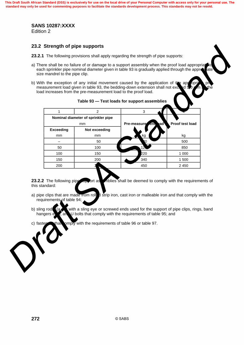
SANS 10287:XXXX Edition 2
272
23.2 Strength of pipe supports
23.2.1 The following provisions shall apply regarding the strength of pipe supports: a) There shall be no failure of or damage to a support assembly when the proof load appropriate to
each sprinkler pipe nominal diameter given in table 93 is gradually applied through the appropriate size mandrel to the pipe clip.
b) With the exception of any initial movement caused by the application of the appropriate pre-
measurement load given in table 93, the bedding-down extension shall not exceed 5,0 mm as the load increases from the pre-measurement load to the proof load.
Table 93 — Test loads for support assemblies
1 2 3 4
Nominal diameter of sprinkler pipe
Pre-measurement load Proof test load mm
Exceeding Not exceeding
mm mm kg kg
– 50 40 500
50 100 120 850
100 150 220 1 000
150 200 340 1 500
200 250 450 2 450
23.2.2 The following pipe support assemblies shall be deemed to comply with the requirements of this standard: a) pipe clips that are made from rolled strip iron, cast iron or malleable iron and that comply with the
requirements of table 94; b) sling rods, (a rod with a sling eye or screwed ends used for the support of pipe clips, rings, band
hangers etc.), and U bolts that comply with the requirements of table 95; and c) fasteners that comply with the requirements of table 96 or table 97.
© SABS
This Draft South African Standard (DSS) is exclusively for use on the local drive of your Personal Computer with access only for your personal use. The
standard may only be used for commenting purposes to facilitate the standards development process. This standards may not be resold.
Draft S
A Stan
dard

SANS 10287:XXXX Edition 2
273
Table 94 — Minimum dimensions of pipe clips
1 2 3 4 5
Nominal diameter of pipe
Type of material
Maximum diameter of hole in clip
Minimum cross-section
mm
Non-corrosion protected ferrous,
other than stainless steel
Corrosion protected ferrous, stainless steel or
non-ferrous
mm
Exceeding Not exceeding mm
– 65 20 × 3,0 20 × 1,2 11
65 100 25 × 3,0 25 × 1,2 11
100 150 32 ×3,0 32 × 1,6 13
150 200 40 × 3,0 40 × 2,0 18
200 250 50 × 3,0 50 × 2,0 22
Table 95 — Sling rods and U bolts
1 2 3
Nominal diameter of pipe Minimum diameter of single
sling rod or bolt mm
Exceeding Not exceeding mm
– 50 8
50 100 10
100 150 12
150 200 16
200 250 20
Table 96 — Coach screws, coach bolts and bolt fasteners
1 2 3 4 5 6 7
Nominal diameter of pipe Coach bolt Coach screw Minimum
number per support
assembly
mm
Exceeding Not
exceeding
Diameter Length Diameter Length
mm mm mm mm
– 50 10 65 10 65 1
50 65 10 65 10 65 2
65 100 10 100 10 100 2
100 150 12 100 10 150 2
100 150 12 150 – 150 2
150 200 12 150 – – 2
200 250 16 200 – – 2
© SABS
This Draft South African Standard (DSS) is exclusively for use on the local drive of your Personal Computer with access only for your personal use. The
standard may only be used for commenting purposes to facilitate the standards development process. This standards may not be resold.
Draft S
A Stan
dard

SANS 10287:XXXX Edition 2
274
Table 97 — Drill or non-drill fasteners in concrete, brickwork
or block-work minimum diameters for drill or non-drill anchors
1 2 3 4
Nominal diameter of pipe Minimum diameter
single fixing Minimum diameter
double fixing mm
Exceeding Not exceeding mm mm
– 50 10 10
50 65 – 10
65 100 – 10
100 200 – 12
200 250 – 20
23.3 CPVC pipe support
23.3.1 The distance between the pipes supports measured along the line of connected pipes, (whether the pipes run nominally horizontally or at some intermediate angle, or change direction), shall not be less than that given in table 98.
23.3.2 Vertical pipes shall be supported at each floor or at 3,0 m intervals, whichever is the smaller distance.
23.3.3 Pipework shall not rely on fittings or joints for support.
23.3.4 All pipe hangers shall have a load bearing surface of not less than 12,7 mm2 and shall be free from any rough or sharp edges which could come into contact with the pipe. They shall be loose fitting and shall allow free axial movement of the pipe.
23.3.5 The amount of bending or snaking in the pipe shall not exceed that as given in the manufacturer’s recommendations.
Table 98 — Maximum distance between pipe supports
1 2
Pipe nominal bore Maximum support spacing
mm mm
25 1 800
32 2 000
40 2 100
50 2 400
65 2 700
80 3 000
23.3.6 Where upright sprinkler heads are used, the maximum horizontal distance from the centre line of the sprinkler to the pipe support shall be 150 mm.
© SABS
This Draft South African Standard (DSS) is exclusively for use on the local drive of your Personal Computer with access only for your personal use. The
standard may only be used for commenting purposes to facilitate the standards development process. This standards may not be resold.
Draft S
A Stan
dard
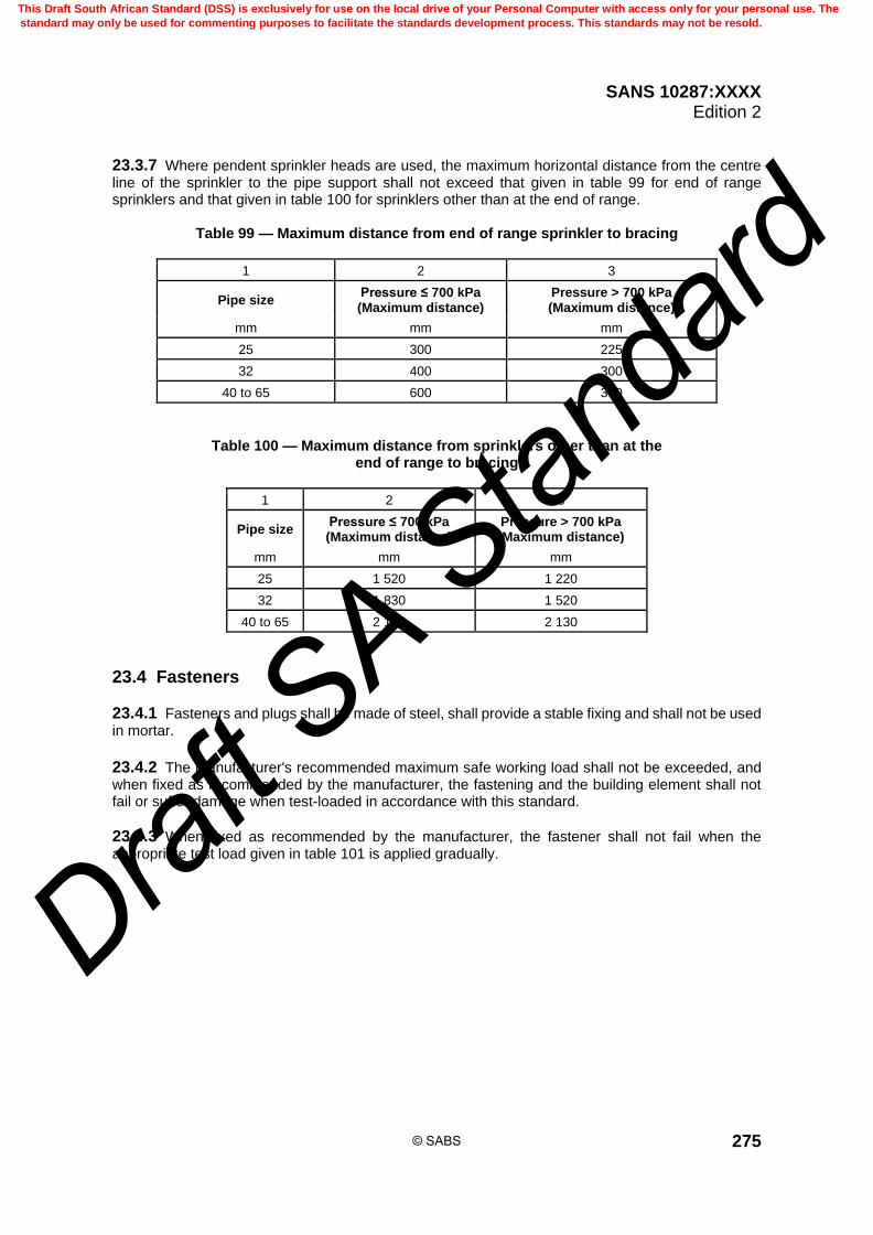
SANS 10287:XXXX Edition 2
275
23.3.7 Where pendent sprinkler heads are used, the maximum horizontal distance from the centre line of the sprinkler to the pipe support shall not exceed that given in table 99 for end of range sprinklers and that given in table 100 for sprinklers other than at the end of range.
Table 99 — Maximum distance from end of range sprinkler to bracing
1 2 3
Pipe size Pressure ≤ 700 kPa (Maximum distance)
Pressure > 700 kPa (Maximum distance)
mm mm mm
25 300 225
32 400 300
40 to 65 600 300
Table 100 — Maximum distance from sprinklers other than at the end of range to bracing
1 2 3
Pipe size Pressure ≤ 700 kPa (Maximum distance)
Pressure > 700 kPa (Maximum distance)
mm mm mm
25 1 520 1 220
32 1 830 1 520
40 to 65 2 130 2 130
23.4 Fasteners
23.4.1 Fasteners and plugs shall be made of steel, shall provide a stable fixing and shall not be used in mortar.
23.4.2 The manufacturer's recommended maximum safe working load shall not be exceeded, and when fixed as recommended by the manufacturer, the fastening and the building element shall not fail or suffer damage when test-loaded in accordance with this standard.
23.4.3 When fixed as recommended by the manufacturer, the fastener shall not fail when the appropriate test load given in table 101 is applied gradually.
© SABS
This Draft South African Standard (DSS) is exclusively for use on the local drive of your Personal Computer with access only for your personal use. The
standard may only be used for commenting purposes to facilitate the standards development process. This standards may not be resold.
Draft S
A Stan
dard

SANS 10287:XXXX Edition 2
276
Table 101 — Test loads for on-site testing of fasteners
1 2 3 4
Nominal diameter of pipe Pre-measurement
load Proof test load mm
Exceeding Not exceeding kg kg
– 50 15 60
50 65 20 80
65 80 40 170
80 100 50 260
100 150 100 510
150 200 100 810
200 250 100 1 290
23.4.4 There shall be no movement as the load is increased from the pre-measurement load to the test load.
23.4.5 Test certificates shall be submitted if required to the installing company, client or client representative.
23.4.6 When installing angle iron brackets for trapeze bars between purlins, table 102 shall be used.
Table 102 — Angle iron brackets – Trapeze or between purlins
1 2 3 4 5 6 7 8
Nominal size of pipe
Trapeze or between purlin span
size
mm
mm 1 900 2 400 2 800 3 300 3 700 4 200 4 700
25 65 × 50 × 5 65 × 50 × 5 65 × 50 × 5 70 × 70 × 6 100 × 65 × 7 100 × 65 × 7 100 × 65 × 7
32 65 × 50 × 5 65 × 50 × 5 65 × 50 × 5 70 × 70 × 6 100 × 65 × 7 100 × 65 × 7 100 × 65 × 7
40 65 × 50 × 5 65 × 50 × 5 65 × 50 × 5 70 × 70 × 6 100 × 65 × 7 100 × 65 × 7 100 × 65 × 7
50 65 × 50 × 5 65 × 50 × 5 65 × 50 × 5 70 × 70 × 6 100 × 65 × 7 100 × 65 × 7 100 × 65 × 7
65 65 × 50 × 5 65 × 50 × 5 65 × 50 × 5 70 × 70 × 6 100 × 65 × 7 100 × 65 × 7 100 × 65 × 7
80 65 × 50 × 5 65 × 50 × 5 75 × 50 × 6 70 × 70 × 6 100 × 65 × 7 100 × 65 × 7 100 × 65 × 7
100 75 × 50 × 6 75 × 50 × 6 75 × 50 × 6 70 × 70 × 6 100 × 65 × 7 100 × 65 × 7 100 × 65 × 7
150 75 × 50 × 6 100 × 65 × 8 100 × 75 × 8 100 × 65 × 7 100 × 65 × 7 100 × 65 ×10 100 × 75 × 10
200 100 × 65 × 8 100 × 75 × 8 100 × 75 × 8 100 × 5 × 7 100 × 65 × 10 100 × 65 × 10 100 × 75 × 10
250 100 × 65 × 8 150 × 75 × 10 150 × 75 × 10 150 × 90 × 15 150 × 90 × 15 150 × 90 × 15 150 × 90 × 15
© SABS
This Draft South African Standard (DSS) is exclusively for use on the local drive of your Personal Computer with access only for your personal use. The
standard may only be used for commenting purposes to facilitate the standards development process. This standards may not be resold.
Draft S
A Stan
dard

SANS 10287:XXXX Edition 2
277
23.5 Spacing and location of hangers
23.5.1 Sprinkler pipes shall not rely on each other for support.
23.5.2 The distance between pipework supports, measured along the line of connected pipes whether the pipes run vertically, nominally horizontally, (which includes pipes with a slope to drain), at some intermediate angle, or change direction, (where pipes change direction, the support spacing dimension is measured along the axis of the connected pipes, and not direct across the angle from support to support), shall not exceed those given in table 103.
Table 103 — Distance between pipe supports
1 2
Nominal diameter of pipe Maximum spacing
mm
Exceeding Not exceeding m
– 65 4,0
65 100 6,1
100 250 6,5
23.5.3 There shall be at least one hanger supporting range pipe lengths between adjacent sprinklers.
23.5.4 There shall be at least one hanger supporting range pipe lengths between a sprinkler and a distribution pipe.
23.5.5 Pipe supports shall be at least 150 mm from the axial centre line of a sprinkler.
23.5.6 The distance from the last hanger to the end of a range pipe shall not exceed 750 mm, but where drop or rise pipes up to 600 mm or horizontal arm pipes up to 450 mm are employed, this distance shall be measured from the end of the drop, rise or arm pipe.
23.5.7 Horizontal arm pipes less than 450 mm or drop or rise pipes less than 600 mm long do not normally require to be supported unless they are at low level or vulnerable to mechanical impact. Pipework shall be prevented from twisting. These measurements are not to be taken cumulatively.
23.5.8 The first hanger on any range pipe shall not be more than 2,0 m from the distribution pipe.
23.5.9 The first hanger on any horizontal distribution pipe shall not be more than 2,0 m from the connection to the main distribution pipe.
23.5.10 The distance from the last hanger to the end of any distribution pipe shall not exceed 450 mm.
23.5.11 Distribution rise or drop pipes shall be secured directly to the building structure or by hangers securing horizontal distribution pipes within 300 mm of the riser.
23.5.12 Distribution rise or drop pipes of less than 1,0 m in length feeding range pipes but not individual sprinklers do not normally require securing.
23.5.13 There shall be at least one pipe support for each mechanical joint in a pipe run.
© SABS
This Draft South African Standard (DSS) is exclusively for use on the local drive of your Personal Computer with access only for your personal use. The
standard may only be used for commenting purposes to facilitate the standards development process. This standards may not be resold.
Draft S
A Stan
dard

SANS 10287:XXXX Edition 2
278
23.5.14 Each section of pipe between two adjacent mechanical joints shall be supported by either a) one support, which shall be located not within the central one-third of the section length, or b) two supports, which shall be separated by not less than one-third of the section length.
23.5.15 Elbows and reducers shall have at least one pipe support that is not more than one-third of the length of the supported pipe away from the fitting on mechanically joined pipes.
23.5.16 On mechanically joined pipes, tees and crosses shall have pipe supports on at least two of the connected pipe lengths, and each support shall be not more than one-third of the length of the relevant supported pipe away from the fitting.
23.6 Corrosion protection Pipe supports in premises or parts of premises where corrosive conditions exist shall be of stainless steel or suitably corrosion-protected.
23.7 Brackets The force on any fixing screw or bolt of a bracket shall not exceed the value of the load supported.
23.8 Split-ring assemblies Split-ring assemblies shall be secured by bolts and nuts.
23.9 Toggle support Toggle supports shall be used only for the support of: a) pipes of nominal diameter 65 mm or less, and then only where no alternative type of hanger can
be used, and b) ranges under ceilings of hollow tile or metal lath and plaster.
23.10 Design and construction
23.10.1 Components of a hanger shall be securely attached to each other by bolts or threaded rod with nuts, lock nuts and washers. Where threaded rod is used, the end of the rod shall terminate not more than 5,0 mm above the top of the pipe the hanger assembly is fitted to in order to prevent undue movement under operational conditions.
23.10.2 Hangers and components in corrosive conditions shall be galvanized.
23.10.3 In any abnormal or highly acidic atmosphere, the hangers and components shall be suitably treated and professional advice shall be obtained.
23.10.4 Split ring assemblies shall be secured by nuts, lock nuts and bolts.
23.10.5 All components shall be true to shape and free from sharp corners. All bolt holes shall be accurately located and free from distortion.
© SABS
This Draft South African Standard (DSS) is exclusively for use on the local drive of your Personal Computer with access only for your personal use. The
standard may only be used for commenting purposes to facilitate the standards development process. This standards may not be resold.
Draft S
A Stan
dard

SANS 10287:XXXX Edition 2
279
23.10.6 Hanger assemblies shall be capable of withstanding loads equivalent to the appropriate proof test loads listed in this standard. The proof test load shall not cause failure or damage to the hanger assembly. Test loads shall be applied to pipe clips using appropriately sized mandrels.
23.10.7 All hanging material shall be approved for sprinkler use and tested to comply with the stress loading in tables 93 and 101.
23.10.8 The manufacturer’s recommended maximum safe working loads for fasteners shall not be exceeded.
23.10.9 Cantilever supports and supplementary supporting steelwork shall be suitable for sprinkler use.
23.10.10 The installing company shall provide the client or his representative with a copy of a certificate stating that the hangers comply with the requirements of this standard.
23.11 Installation
23.11.1 It may be necessary to use flexible pipe or swivelling couplings to allow relative movement of the two parts of the installation.
23.11.2 Unless otherwise allowed within this standard, hangers shall support the pipes directly from the building structure and shall not be used to support any other objects, with the exception of a primary support specially designed for the suspension of several pipes, in which case the supports and in particular the primary support shall be tested for the full load.
23.11.3 The building itself shall be capable of supporting the additional load of water filled pipework and shall not impair the performance of sprinklers under a fire condition.
23.11.4 Pipes shall wherever possible be supported from non-combustible building components in preference to those of combustible materials.
23.11.5 Where pipework rests on a support it shall be secured in position.
23.11.6 The pipes shall be supported independently of the roofing or ceiling cladding and any associated suspension system.
23.11.7 In cases where sprinkler protection is installed below duct work and the pipes cannot be supported from the building structure, pipes may be supported from a steel section supporting the duct work, providing that the steel section and its existing attachments to the building are of sufficient size and shape to support the combined weight of the duct work and water-filled sprinkler pipe.
23.11.8 Hangers shall not be screwed into tee pieces or crosses which are part of the sprinkler installation pipework.
23.11.9 Hangers, other than toggle hangers, which may be attached to the swivel rod by rivets, shall be held together by bolts, or threaded rods, with nuts and washers.
23.11.10 Hangers whose sole means of fixing uses the elasticity of the materials of which they are made, i.e. spring clips shall not be used.
23.11.11 Main feed and main distribution pipes shall not be supported from the roof purlins alone. Purlins may be used as intermediate supports only in conjunction with trapeze bars.
© SABS
This Draft South African Standard (DSS) is exclusively for use on the local drive of your Personal Computer with access only for your personal use. The
standard may only be used for commenting purposes to facilitate the standards development process. This standards may not be resold.
Draft S
A Stan
dard
SANS 10287:XXXX Edition 2
280
23.11.12 Sprinkler pipes shall be supported from the building structure, which itself shall be capable of supporting the additional load of the water-filled pipework and shall not impair the performance of sprinklers under fire conditions.
23.11.13 Sprinkler supports shall not be used to support any other objects except where primary support is designed for the suspension of piped services.
23.11.14 Sprinkler pipes shall not be supported from ceiling sheathing or cladding or from any associated suspension system.
23.11.15 Only pipes of nominal diameter 50 mm or less shall be suspended from metal deck roofs, for example roofs of which the cross section is trapezoid.
23.11.16 All parts shall be true to shape and free from burrs and sharp edges, and bolt holes shall be accurately located and free from distortion.
23.11.17 Hangers shall not be welded or secured direct to sprinkler pipework, (for example, as a redundant tee or cross-fitting), or to structural steel work, or to any portion of the building.
23.11.18 Pipework that rests on a support shall be secured in position and branching pipes shall not rely on each other for support.
23.11.19 Pipework shall be restrained against twisting and misalignment.
23.11.20 Wherever possible, sprinkler pipes shall be supported from non-combustible building elements. Where combustible building elements are used for support, extra protection might be provided by appropriate positioning of sprinklers or by using an appropriate type of sprinkler.
23.12 Fastening to timber
23.12.1 Wood screws and nails shall be not used for fixing hangers and explosively powered fasteners shall not be used on timber.
23.12.2 Coach screws, coach bolts and bolts shall be located at least 10 shank diameters apart (centre-to-centre) and the thread of coach screws shall be completely engaged in the structural timber work.
23.12.3 Pilot holes of the diameter and depth recommended by the manufacturer shall be drilled before coach screws are fitted.
23.12.4 Where the shank of a coach screw or bolt enters structural timber work, clearance of the appropriate length shall be drilled to prevent the timber work from splitting.
23.12.5 Coach screws, coach bolts and bolts fixed in the side of a timber joist shall a) at least be 65 mm above the lower edge of the joist when they support pipes of nominal diameter
65 mm or less, or b) at least be 80 mm above the lower edge when they support pipes of nominal diameter exceeding
65 mm.
23.13 Fastenings to concrete, brickwork or block work
23.13.1 Expansion shield fasteners shall be used in brickwork or block work.
© SABS
This Draft South African Standard (DSS) is exclusively for use on the local drive of your Personal Computer with access only for your personal use. The
standard may only be used for commenting purposes to facilitate the standards development process. This standards may not be resold.
Draft S
A Stan
dard
SANS 10287:XXXX Edition 2
281
23.13.2 When drilling into the building structure, care shall be taken to avoid crumbling of the structure around the hole.
23.13.3 Holes in the face of a concrete beam shall be sufficiently distant from the lower edge to avoid the reinforcing rods, and to prevent flaking of the concrete.
23.13.4 Explosive powered fasteners shall be not used in concrete, brickwork or block work.
23.13.5 Expanding all-steel fasteners or set-in fasteners may be used in structural grade concrete.
24 Types of systems
24.1 General
24.1.1 The types of systems covered by this standard are classed as standard sprinkler systems that may incorporate subsidiary special protection in the form of sealed medium velocity sprayers or open medium (or both) or high velocity sprayers fed through sealed multiple-jet-controls, in relatively small areas involving flammable liquid hazards, for example oil-fired boiler rooms, paint storage areas.
24.1.2 These systems include but are not necessarily limited to the following: a) wet pipe system; b) alternate wet and dry pipe system; c) wet pipe or alternate wet and dry pipe system incorporating tail end dry pipe systems; d) wet pipe system incorporating tail end alternate systems; e) dry pipe systems f) pre-action system; g) recycling pre-action system; and h) deluge systems using open sprinklers or medium (or both) or high velocity sprayers.
24.2 Number of sprinklers controlled by valve sets Sprinkler systems shall be so designed to ensure that the number of sprinklers controlled by one set of valves is logically zoned in either contiguous square area or number of sprinklers in accordance with table 104.
© SABS
This Draft South African Standard (DSS) is exclusively for use on the local drive of your Personal Computer with access only for your personal use. The
standard may only be used for commenting purposes to facilitate the standards development process. This standards may not be resold.
Draft S
A Stan
dard

SANS 10287:XXXX Edition 2
282
Table 104 — Number of sprinklers per valve (excluding life safety premises)
1 2 3
Hazard or class Square area
Number of sprinklers m2
Wet pipe ordinary hazard Void is cumulative if communication exists
12 000 1 000
Wet pipe high hazard Void is cumulative if communication exists
9 000 1 000
Intermediate level protection Racking and shelving
4 000 1 000
ESFR protection N/A 1 000
Alternate wet and dry or dry pipe ordinary and high hazard with an accelerator or exhauster
N/A 500
Alternate wet and dry or dry pipe ordinary and high hazard without an accelerator or exhauster
N/A 250
Recycling pre-action system N/A 1 000
Pre-action system N/A 1 000
Tail end systems N/A 100
24.3 Wet pipe systems
24.3.1 A wet pipe system is a standard sprinkler system permanently charged with water under pressure both above and below the installation alarm valve.
23.3.2 Wet pipe systems shall be installed in premises where there is no danger at any time of the water in the pipes freezing. Where these conditions cannot be ensured throughout the premises, the areas which are unheated may be on a tail end alternate wet and dry pipe system, provided the number of sprinklers thereon does not exceed the limits referred to in table 104 otherwise, the installation shall be erected on the alternate wet and dry pipe system.
23.3.3 Sprinklers in wet pipe systems may be installed in either the upright or pendent position.
23.3.4 Wet pipe systems shall be so designed that either the number of sprinklers or area controlled by one set of valves does not exceed that stated in table 104.
23.3.5 In designing the area covered by a set of valves, cognisance shall be taken of logically zoning the roof level protection with intermediate rack or shelf level protection.
23.3.6 Rack or shelf protection may not overlap multiple valve configurations for roof level protection.
23.3.7 In calculating the total number of sprinklers on one set of valves in wet pipe systems, the number of sprinklers in concealed spaces or in machines, etc., may be ignored.
24.4 Alternate wet and dry pipe systems
24.4.1 A composite valve is suitable for wet, dry or alternate operation whereas a dry alarm valve is suitable for a dry system or an alternate installation.
24.4.2 A subsidiary stop valve which is approved shall be fitted above the alarm valve in order to exercise the valve.
© SABS
This Draft South African Standard (DSS) is exclusively for use on the local drive of your Personal Computer with access only for your personal use. The
standard may only be used for commenting purposes to facilitate the standards development process. This standards may not be resold.
Draft S
A Stan
dard

SANS 10287:XXXX Edition 2
283
24.4.3 An alternate wet and dry pipe system is a standard sprinkler system embodying either a composite alarm valve or a combination set comprising an alarm, (wet pipe), valve and an alarm, (dry pipe), valve where a) during the winter months the system piping above the composite or alarm, (dry pipe), valve is
charged with air under pressure, and the remainder of the system below the valve with water under pressure, and
b) at other times of the year the system operates as a wet pipe system.
24.4.4 Sprinklers in alternate wet and dry pipe systems shall be installed in the upright position above the line of pipes. An exception to this rule is allowed if dry pendent pattern sprinklers which are approved are installed or where standard sprinklers erected pendent have an anti-freezing device incorporated which is approved.
24.4.5 Pipework shall be arranged with adequate slope for drainage as described in this standard.
24.4.6 Alternate wet and dry pipe systems shall be so designed that the number of sprinklers controlled by one set of valves, (inclusive of tail end extensions), does not exceed that stated in this standard.
24.5 Dry pipe system
24.5.1 A subsidiary stop valve which is approved shall be fitted above the alarm valve in order to exercise the valve.
24.5.2 Fast response sprinklers used for dry pipe systems assist in getting water to the remote sprinklers faster due to the speed of operation and the likelihood of more sprinklers opening at the incipient stage of fire.
24.5.3 A dry pipe system is a standard sprinkler system in which the system pipework is permanently charged with air under pressure above the alarm (dry pipe) valve and with water under pressure below the valve.
24.5.4 Dry pipe systems are normally allowed in buildings where the temperature conditions are artificially maintained at less than 5 °C or less such as in cool stores, fur vaults, or where the temperature is maintained above 70 °C as in drying ovens, etc. Special approval is required for dry pipe systems in other circumstances.
24.5.5 Alarm (dry pipe), valves in dry pipe systems shall be exercised at least once every six months. This may be accomplished by removing the inspection cover plate and manually operating the moving parts.
24.5.6 Dry pipe systems shall be so designed that the number of sprinklers controlled by one set of valves does not exceed the limits laid down in this standard for alternate wet and dry pipe systems.
24.5.7 Sprinklers shall be installed in the upright position above the line of pipes in dry pipe systems. An exception to this rule is when dry pendent pattern sprinklers which are approved are installed or where standard sprinklers installed in the pendent position have an anti-freezing device incorporated which is approved.
24.5.8 Pipework shall be arranged with adequate slope for drainage as described in this standard.
© SABS
This Draft South African Standard (DSS) is exclusively for use on the local drive of your Personal Computer with access only for your personal use. The
standard may only be used for commenting purposes to facilitate the standards development process. This standards may not be resold.
Draft S
A Stan
dard

SANS 10287:XXXX Edition 2
284
24.6 Pre-action system
24.6.1 A subsidiary stop valve which is approved shall be fitted above the alarm valve in order to exercise the valve.
24.6.2 A pre-action system is a combination of a standard sprinkler system and an independent system of heat or smoke detectors (or both) which is approved and installed in the same areas as the sprinklers. In general, heat or smoke detectors (or both) operate prior to sprinklers, and so a pre-action valve will open to allow water to flow into the sprinkler pipework before the first sprinkler operates.
24.6.3 The sprinkler system pipework is normally charged with air under pressure and is monitored so that an alarm is given on reduction of the air pressure.
24.6.4 The pre-action alarm valve controlling the water supply is operated either a) Solely by the system of detectors which are approved to allow the sprinkler pipework to become
charged with water, thus reverting to a wet pipe system. The object is to prevent a discharge of water from pipework or sprinklers that have suffered mechanical damage, or
b) By the system of detectors which are approved, or independently by the operation of a sprinkler
releasing the air from the sprinkler pipework (or both). The object is to facilitate an earlier discharge of water from sprinklers on a dry pipe system. Operation of the sprinkler system is unaffected by any failure in the detector system.
24.6.5 In each case the detection system also automatically operates an alarm. The heat or some detection system shall operate a continuously energized valve which is approved, or trip mechanism, to release the pre-action alarm valve when the valve or trip mechanism becomes de-energized.
24.6.6 The maximum number of sprinklers controlled by a pre-action valve, whether in heated or unheated buildings, is 1 000. Sprinklers shall be installed in the upright position and the pipework shall be arranged with an adequate slope for drainage as described in this standard.
24.7 Recycling pre-action system
24.7.1 A subsidiary stop valve which is approved shall be fitted above the alarm valve in order to exercise the valve.
24.7.2 A recycling pre-action system is of the type described in pre-action systems with heat detectors and incorporating a special pre-action flow control valve capable of repeated on/off cycles appropriate to the possible redevelopment of fire in the protected area.
24.7.3 The cycling occurs as a result of heat detector operation which, acting as an electrical interlock, causes the pre-action flow control valve to open and close.
24.7.4 As a safety measure, the re-closing of the flow control valve is delayed for a predetermined period, (usually 5 min), by means of an automatic timer. If, however, the fire rekindles and re-actuates the heat detectors, the flow control valve is reopened without delay and water will again flow from the open sprinklers.
24.7.5 The objects of the recycling pre-action system are a) to restrict water damage after a fire has been extinguished, b) to obviate the need to close the main stop valve when affecting modifications to the system
pipework or the replacement of sprinklers, and
© SABS
This Draft South African Standard (DSS) is exclusively for use on the local drive of your Personal Computer with access only for your personal use. The
standard may only be used for commenting purposes to facilitate the standards development process. This standards may not be resold.
Draft S
A Stan
dard
SANS 10287:XXXX Edition 2
285
c) to avoid water damage caused by accidental mechanical damage to the system pipework or
sprinklers.
24.7.6 The heat detectors shall be spaced not more than 12,0 m apart and not more than 6,0 m from walls. 24.7.7 Sprinklers shall be installed in the upright position and the pipework shall be arranged with an adequate slope for drainage as described in this standard. 24.7.8 Sprinklers may, however, be installed in the pendent position where the system is installed in an adequately heated building.
24.8 Deluge systems 24.8.1 A subsidiary stop valve which is approved shall be fitted above the alarm valve in order to exercise test the valve. 24.8.2 Deluge systems are systems of open sprinklers or nozzles controlled by a quick opening valve (deluge valve), which is operated by a system of heat detectors or sprinklers which are approved and installed in the same areas as the open sprinklers. 24.8.3 Where sprinklers are used as the detector line, these shall be purpose made. 24.8.4 These systems are designed primarily for special hazards where intensive fires with a very fast rate of fire propagation are expected, and it is desirable to apply water simultaneously over a complete zone in which a fire may originate by admitting water to open sprinklers or to medium or high velocity sprayers.
24.9 Tail end alternate wet and dry pipe or tail end dry pipe systems
24.9.1 A subsidiary stop valve which is approved shall be fitted downstream of the tail end valve in order to exercise the valve.
24.9.2 These systems are essentially similar to alternate and dry pipe systems as described in this standard except that they are of comparatively small extent and form extensions to standard sprinkler installations.
24.9.3 These systems are permitted as an extension in a) Comparatively small areas where there is possible frost danger in an otherwise adequately heated
building. b) High temperature ovens or stoves. The tail end systems would be on the alternate wet and dry
pipe principle in case of frost danger and on the dry pipe principle in the case of freezers. c) An alternate wet and dry pipe system in high temperature ovens or stoves, when the tail end
systems would be on the dry pipe principle.
24.9.4 Sprinklers in tail end systems shall be installed in the upright position above the line of pipes. An exception to this rule is allowed if dry pendent pattern sprinklers which are approved and are installed or where standard sprinklers erected pendent have an anti-freezing device incorporated which is approved.
24.9.5 The number of sprinklers in a group of tail end systems controlled by one set of wet pipe system or alternate wet and dry pipe system valves shall not exceed 250 in the aggregate with no more than 100 sprinklers on any one tail end system.
© SABS
This Draft South African Standard (DSS) is exclusively for use on the local drive of your Personal Computer with access only for your personal use. The
standard may only be used for commenting purposes to facilitate the standards development process. This standards may not be resold.
Draft S
A Stan
dard

SANS 10287:XXXX Edition 2
286
24.9.6 Each tail end system shall be provided with a 50 mm drain valve and drain pipe and a pressure gauge fitted at a point above the seating of the tail end valve.
24.9.7 Each tail end system shall be controlled by a subsidiary stop valve as specified in this standard and shall include either a water flow alarm switch or an electric alarm pressure or flow switch to indicate the particular section operating. These sectional warning systems are additional to the water motor alarm on the main control valve.
25 Cold room and freezer protection
25.1 General
25.1.1 In cold storage warehouses refrigerated by air circulation, automatic means shall be provided to shut down the air circulation system immediately on detection of a fire or when the sprinkler system operates.
25.1.2 If there is a false ceiling within the cold chamber forming a plenum for the air circulation system, dry pendent sprinklers will also be required therein.
25.1.3 Sprinklers shall be installed in positions where there is no likelihood of mechanical damage through movement of goods.
25.1.4 Any sprinklers, other than flush sprinklers, installed in a position where there is a risk of accidental damage shall be fitted with a metal guard suitable for the purpose of protecting the sprinkler head.
25.2 Design performance
25.2.1 The water discharge time of dry, pre-action sprinkler systems, including any subsidiary dry pipe extension in cold stores or where used in other applications, shall be determined by calculation at the design stage.
25.2.2 The discharge time performance shall be confirmed by tests at the commissioning stage using the remote test valve as specified in this standard.
25.2.3 The maximum time between sprinkler operation and water discharge shall not be more than the value given in table 105.
Table 105 — Maximum time difference between sprinkler operation and water discharge
1 2
Hazard class Maximum time between sprinkler operation and water discharge
s
Ordinary hazard 60
High hazard 30
25.3 Pipework
23.3.1 The installation design shall allow for the inspection of pipework to establish that it is free from ice or other obstructions. Provision shall be made for the thorough purging of moisture after valve operation.
25.3.2 Installation pipework shall be above ground and accessible.
© SABS
This Draft South African Standard (DSS) is exclusively for use on the local drive of your Personal Computer with access only for your personal use. The
standard may only be used for commenting purposes to facilitate the standards development process. This standards may not be resold.
Draft S
A Stan
dard

SANS 10287:XXXX Edition 2
287
25.3.3 The pipework shall be easily dismantled. 25.3.4 At the point of entry of the pipework into the cold chamber and otherwise where practicable, a change by direction shall be made by a tee with one branch sealed off to allow for inspection. 25.3.5 Pipe fittings shall be fit for purpose and shall facilitate easy removal of the pipework. 25.3.6 Consideration shall be given to the use of compression fittings, mechanical pipe couplings or preferably flanged joints. 25.3.7 Pipe supports shall be such as to facilitate easy removal of the pipework. Hangers of the split ring type secured by hexagonal head bolts and hexagonal nuts are recommended.
25.4 Pressurization of dry installation pipework 25.4.1 The installation pipework downstream of the dry system installation control valve and any tail end control valve shall be pressurized with either a) dry nitrogen gas, or b) air drawn across freezers of lowest temperature in the plant and through a chemical dehydrator. 25.4.2 Nitrogen is an asphyxiating gas and the system owner and user shall be consulted about its use as a pressurizing agent to enable a risk assessment to be carried out. 25.4.3 Nitrogen cylinders shall be fitted with a suitable pressure reducing valve to control the pressure. 25.4.4 A pressure relief valve shall be fitted, to operate at the upper limit of the required installation gas pressure. 25.4.5 The system shall be provided with a low air or gas pressure alarm.
25.5 Pressurization of tail end installations on dry pipe systems 25.5.1 The air or gas pressure in a series of tail-end installations, on one set of main installation control valves operating on the dry pipe or alternate wet and dry pipe principle, shall not be less than the pressure in the feed pipe(s) between the main installation control valve and the tail-end dry pipe. 25.5.2 Differential dry pipe valves used in tail-end installations connected to an installation operating on the dry pipe or alternate wet and dry principle shall be suitable for sprinkler service and shall retain a pressure in the installation pipework between the main control valve and the underside of the tail end dry pipe or valves.
25.6 Dry pendent or upright sprinkler pipe length 25.6.1 The length of the drop or rise pipe on a dry sprinkler within the heated area shall be of sufficient length to prevent freezing at the wet pipe end due to conduction of heat to the cold store. 25.6.2 Where the temperature of the freezer is above −30 °C, the length of the dry pendent dropper above the top of the cold room or freezer insulation shall not be less than 305 mm. Where the temperature of the cold room or freezer is equal to or lower than −30 °C, the minimum length for the drop pipe above the top of the cold room or freezer insulation shall be determined by using the following equation: L = 0,0137 × (Tc + 6,67) + I where
© SABS
This Draft South African Standard (DSS) is exclusively for use on the local drive of your Personal Computer with access only for your personal use. The
standard may only be used for commenting purposes to facilitate the standards development process. This standards may not be resold.
Draft S
A Stan
dard

SANS 10287:XXXX Edition 2
288
L is the minimum length of the drop pipe in metres (m), within the heated area, i.e. drop pipe
length exposed in the heated area. It shall not include the length covered by cold store ceiling insulation or exposed to cold store temperature, which shall be added;
Tc is the minimum temperature of the cold store in degrees celsius (°C). I is the thickness of the ceiling insulation composite panel in metres (m)
25.6.3 The dry pendent dropper shall not be attached to the fabric of the cold room with mastic or insulating material that permanently bonds the dropper to the refrigerated structure.
25.6.4 In the event of collapse of the cold room, the cold room material shall drop away from the sprinkler system.
25.7 Dry pendent or upright calculation
25.7.1 For water flow and pressure calculations, the K-Factor shall include the friction loss in the drop pipe of the unit and if appropriate the effect of any internal mechanical device for obstruction.
25.7.2 The static head gain or loss in the drop or rise pipe respectively shall be allowed for in the hydraulic calculations.
25.8 Dry pendent or upright sprinkler inspection
25.8.1 Dry sprinklers shall be inspected at regular intervals for ice build-up or signs of ice formation in the sprinkler rise or drop pipe. Visual inspections shall take place at least bi-annually.
25.8.2 Water and water vapour ingress into a dry drop sprinkler shall be avoided. Water ingress may occur at a) the valve due to a faulty seal; and b) the connection between the drop pipe and dry sprinkler valve assembly due to poor seals allowing
atmospheric pressure changes and pressure differentials to draw moist air into the dry sprinkler pipe.
25.8.3 Significant pressure differentials may be more prevalent in small cold stores, where the effect of door openings is more significant and with units where they may be cyclical temperature changes.
25.8.4 Any water ingress into the sprinkler pipe will freeze, resulting in ice build-up. Ice build-up may seriously impair sprinkler performance and may prevent sprinkler operation or cause obstructions to the water flow.
25.8.5 Where ice build-up occurs or if ice extrudes through any drain aperture in the sprinkler heat sensitive element support, the dry sprinkler assembly shall be removed and replaced.
26 Anti-freeze systems
26.1 General
26.1.1 Where at all possible, a dry pipe system would be the preferred method of protection as the use of anti-freeze systems is not recommended and the maintenance requirement for anti-freeze systems is onerous and, as a result, would be subject to failure.
© SABS
This Draft South African Standard (DSS) is exclusively for use on the local drive of your Personal Computer with access only for your personal use. The
standard may only be used for commenting purposes to facilitate the standards development process. This standards may not be resold.
Draft S
A Stan
dard

SANS 10287:XXXX Edition 2
289
26.1.2 CPVC sprinkler pipe and fittings which are approved shall be protected from freezing with glycerine only. The use of diethylene, ethylene, or propylene glycols shall be specifically prohibited.
26.1.3 Before commissioning, an anti-freeze system shall be hydrostatically tested with air to 250 kPa for 24 h.
26.1.4 Where deepfreeze conditions or any condition where water in the pipes is liable to freeze with resultant damage, the following systems may be employed: a) dry pendent droppers or dry pendent ESFR systems; b) dry pipe systems; or c) where there is no other viable alternative, anti-freeze systems.
26.1.5 The normal air systems are not suitable where freezing conditions occur as compressed air invariably has a moisture content which is liable to collect at the lowest point in the pipework with resultant damage to the pipes. Where compressed air systems are used and to overcome the moisture content, the air is to be drawn from within the freezer compartment and through a dehumidifier before being introduced into the dry pipe sprinkler system.
26.1.6 The air circulation fans shall be closed down automatically on operation of the sprinkler system.
26.2 Anti-freeze solutions 26.2.1 Only factory premixed anti-freeze solutions specifically formulated for sprinkler systems and provided by or endorsed by the manufacturer of the sprinkler system components used can be used to ensure that the mixture is consistent and that the concentration levels are as required. 26.2.2 Signage at the control valve assembly and entry to the areas where anti-freeze systems are used shall clearly identify the following: a) the manufacturer of the anti-freeze; b) the type and brand of anti-freeze used; c) the concentration of the anti-freeze solution; and d) the volume of the anti-freeze solution in the system. 26.2.3 The use of anti-freeze solutions shall comply with relevant regulations. 26.2.4 An anti-freeze solution shall be supplied by or endorsed by the manufacturer with a freezing point of 10 % or 5 °C, whichever is the greater, below the expected minimum temperature for the locality. 26.2.5 The specific gravity of the prepared solution shall be checked by a hydrometer with suitable scale. 26.2.6 Where ESFR protection is installed, the entire system, premixed anti-freeze solutions used as well as the ESFR sprinkler heads and all related equipment shall be approved and listed for that purpose.
26.3 Arrangement of supply piping and valves
26.3.1 The valve arrangement, equipment and supply pipe layout shall comply with the manufacturer’s requirements.
© SABS
This Draft South African Standard (DSS) is exclusively for use on the local drive of your Personal Computer with access only for your personal use. The
standard may only be used for commenting purposes to facilitate the standards development process. This standards may not be resold.
Draft S
A Stan
dard

SANS 10287:XXXX Edition 2
290
26.3.2 Before freezing weather each year, the solution in the entire system shall be emptied into convenient containers and either replaced or, if allowable, brought to the proper specific gravity by adding concentrated liquid as needed and in accordance with the sprinkler manufacturer’s requirements. The resulting solution may be used to refill the system.
26.3.3 Where the system is continually under freezing conditions, the solution shall be checked every three months.
26.4 Anti-freeze systems solution maintenance
26.4.1 Using installation records, maintenance records, and information from the owner, chemical tests, or other reliable sources of information, the type of anti-freeze in the system shall be determined as follows: a) if the type of anti-freeze is found to be a type that is no longer permitted, the system shall be
drained completely and replaced with an acceptable solution; b) if the type of anti-freeze cannot be reliably determined, then the system shall be drained completely
and replaced with a premixed solution acceptable to the manufacturer of the equipment installed; c) if the anti-freeze is not required to be replaced in accordance with (a) and (b) above, test samples
shall be taken at the top of each system and at the bottom of each system; d) the specific gravity of each solution shall be checked using a hydrometer with a suitable scale or a
refractometer having a scale calibrated for the anti-freeze solution; e) if a concentration is varies from what was originally approved to keep the fluid from freezing,
alternate methods of preventing the pipe from freezing shall be employed; and g) if any of the samples exhibits a concentration in excess or lower than what is permitted, the system
shall be emptied and refilled with a new acceptable premixed solution.
26.4.2 Maintenance shall be carried out annually before the onset of freezing weather, or every three months in the case where the system is continually under freezing weather. The anti-freeze solution shall be tested as follows: a) the manufacturer’s instructions shall be used with regard to the number of test points and refill
procedure. b) if the most remote portion of the system is not near the top or the bottom of the system, an
additional sample shall be taken at the most remote portion; c) if the connection to the water supply piping is not near the top or the bottom of the system, an
additional sample shall be taken at the connection to the water supply; d) the anti-freeze solution shall be tested at its most remote portion and where it interfaces with the
wet pipe system. e) where anti-freeze systems have a capacity larger than 568 L, tests at one additional point for every
379 L shall be made. f) if the results indicate an incorrect freeze point at any point in the system, the system shall be
drained and refilled with new premixed anti-freeze; NOTE Sampling from the top and bottom of the system helps to determine if the solution has settled. Anti-
freeze solutions are heavier than water;
© SABS
This Draft South African Standard (DSS) is exclusively for use on the local drive of your Personal Computer with access only for your personal use. The
standard may only be used for commenting purposes to facilitate the standards development process. This standards may not be resold.
Draft S
A Stan
dard

SANS 10287:XXXX Edition 2
291
g) if the anti-freeze compound is separating from the water due to poor mixing, it will exhibit a higher concentration in the lower portion of the system than in the upper portion of the system;
h) if the concentration is acceptable near the top, but too low near the water connection, it may mean
that the system is becoming diluted near the water supply; and i) if the concentration is either too high or too low in both the samples, it may mean that the wrong
concentration was added to the system.
26.4.3 Test samples are to be drawn 4 times per annum especially if any portion of the system has been drained for maintenance or repairs.
26.4.4 A small hydrometer can be used so that a small sample is sufficient.
26.4.5 Where the sample indicates that the solution has become weakened, the entire system shall be emptied and refilled with acceptable solution.
26.4.6 Where systems are drained in order to be refilled, it is not typically necessary to drain drops as most systems with drops have insufficient volume to cause a problem, even if slightly higher concentration solutions collect in the drops.
26.4.7 For drops in excess of 1,0 m, drops shall be drained if there is evidence that unacceptably high concentrations of anti-freeze have collected in these.
26.4.8 When emptying and refilling anti-freeze solutions every attempt shall be made to recycle the old solution with the anti-freeze manufacturer rather than discarding it.
26.5 Anti-freeze systems calculation requirements For anti-freeze systems greater than 150 L in size, the friction losses shall be calculated using the Darcy-Weisbach formula.
27 High rise and life safety buildings
27.1 General
27.1.1 Notwithstanding the requirements within this standard, special considerations given in 27.1.2 apply to high rise buildings and other life safety occupancies such as hotels.
27.1.2 A life safety environment is classed as a building which is open to the general public, on entering such a building the public would generally not be familiar with the layout. Life safety buildings may be buildings where the occupants are incapacitated or incarcerated. Such buildings include, but are not necessarily limited to: a) High rise buildings. b) Stand-alone office blocks or where fed from a separate set of valves in the case of warehouses. c) Hotels. d) Shopping centres: shopping centres generally do not require fast response sprinkler systems to
be installed. These structures fall largely into the high hazard categories due to the storage that takes place and in such instances, the maximum allowable temperature rating of the sprinklers shall not exceed 93 °C; in all other instances the use of 68 °C sprinklers is required.
e) Places of worship. f) Exhibition halls.
© SABS
This Draft South African Standard (DSS) is exclusively for use on the local drive of your Personal Computer with access only for your personal use. The
standard may only be used for commenting purposes to facilitate the standards development process. This standards may not be resold.
Draft S
A Stan
dard

SANS 10287:XXXX Edition 2
292
g) Places of entertainment for example, cinemas, convention centres, concert halls and theatres. h) Hospitals, medical centres, clinics. i) Education centres for example, schools, universities and libraries. j) Retirement centres, old age homes, frail care facilities, prisons, mental institutions.
27.1.3 High rise sprinkler installations shall be subdivided into sprinkler installations such that the height difference between the highest and lowest sprinkler on any installation does not exceed 45,0 m.
27.1.4 Pipework, fittings, valves and other equipment shall be capable of withstanding the maximum pressures likely to be encountered for a high rise building.
27.2 Ordinary hazard
27.2.1 Life safety occupancy include, but are not necessarily limited to, hotels, office blocks and buildings over 30,0 m in height or of such a height that the fire brigade cannot effect evacuation from street level with their own equipment.
27.2.2 Where fast response sprinklers which are approved with a response time index of less than 50 are used for the protection of life safety occupancies, excluding storage and process risks, shopping centres and any structure where the ceiling height exceeds 6,0 m the assumed maximum area of operation may be reduced in accordance with table 106.
Table 106 — Ordinary hazard life safety occupancies
1 2
Ceiling height Allowable reduction in the assumed maximum area
of operation
m %
≤ 3,0 40
≥ 3,0 to ≤ 3,75 35
≥ 3,75 to ≤ 4,5 30
≥ 4,5 to ≤ 5,25 25
≥ 5,25 to ≤ 6,0 20
> 6,0 0
27.2.3 In life safety occupancies, the sprinkler installation shall provide progressive protection for the building whilst under construction. 27.2.4 Where the room design method is used for determining the assumed maximum area of operation for ordinary hazard life safety occupancies, for hotels and guest houses or residencies, the water supply flow and pressure requirements shall be based on the room(s) which creates the greatest demand subject to a minimum of five sprinklers in operation. This method of determining the assumed maximum area of operation shall encompass a section of corridor of not less than 24,0 m in length or six sprinklers whichever is the greater.
27.2.5 To utilize the room design method, the partitions or separating elements between the rooms shall be equal to or greater than the duration of the water supply for the sprinkler installation. No area, other than corridors shall exceed 130 m2. Failing which, the protection shall be based on ordinary hazard design parameters with an area of operation of not less than 216 m2.
© SABS
This Draft South African Standard (DSS) is exclusively for use on the local drive of your Personal Computer with access only for your personal use. The
standard may only be used for commenting purposes to facilitate the standards development process. This standards may not be resold.
Draft S
A Stan
dard

SANS 10287:XXXX Edition 2
293
27.3 Control valve assemblies 27.3.1 Each installation shall be provided with a set of installation control valves as specified in this standard and in accordance with figure 53. NOTE Non-return valves on the by-pass stop valves are optional for dedicated pump water supply. See figure 53. 27.3.2 The installation control valves shall be located in the central core close to the main escape stairs, where the valves are positioned at various levels of the building. The number of installation control valves is determined by either zoning in accordance with 27.7 or table 104. 27.3.3 The installation control valves shall be located in a sprinkler protected area controlled by another set of valves. 27.3.4 An indication plate shall be installed adjacent to each set of installation valves displaying the number of the installation and the number of floors which it controls. 27.3.5 Each installation shall be fitted with a water motor alarm which is approved in accordance with this standard. 27.3.6 An electric alarm pressure switch which is approved shall be fitted to each installation control valve, which will indicate on the central control panel the particular installation which is operating. 27.3.7 Each installation control valve shall be fitted with fire brigade booster connection inlet in accordance with this standard. 27.3.8 Each installation shall have its own proving arrangement incorporating a sight glass. Adequate drainage shall be provided. 27.3.9 The sprinkler risers feeding the installation control valves shall run through the sprinkler protected areas or be housed in fireproof ducts with a minimum of 2 h fire resistance. The fireproof duct shall not have any openings or communicate in any way with unprotected openings.
© SABS
This Draft South African Standard (DSS) is exclusively for use on the local drive of your Personal Computer with access only for your personal use. The
standard may only be used for commenting purposes to facilitate the standards development process. This standards may not be resold.
Draft S
A Stan
dard
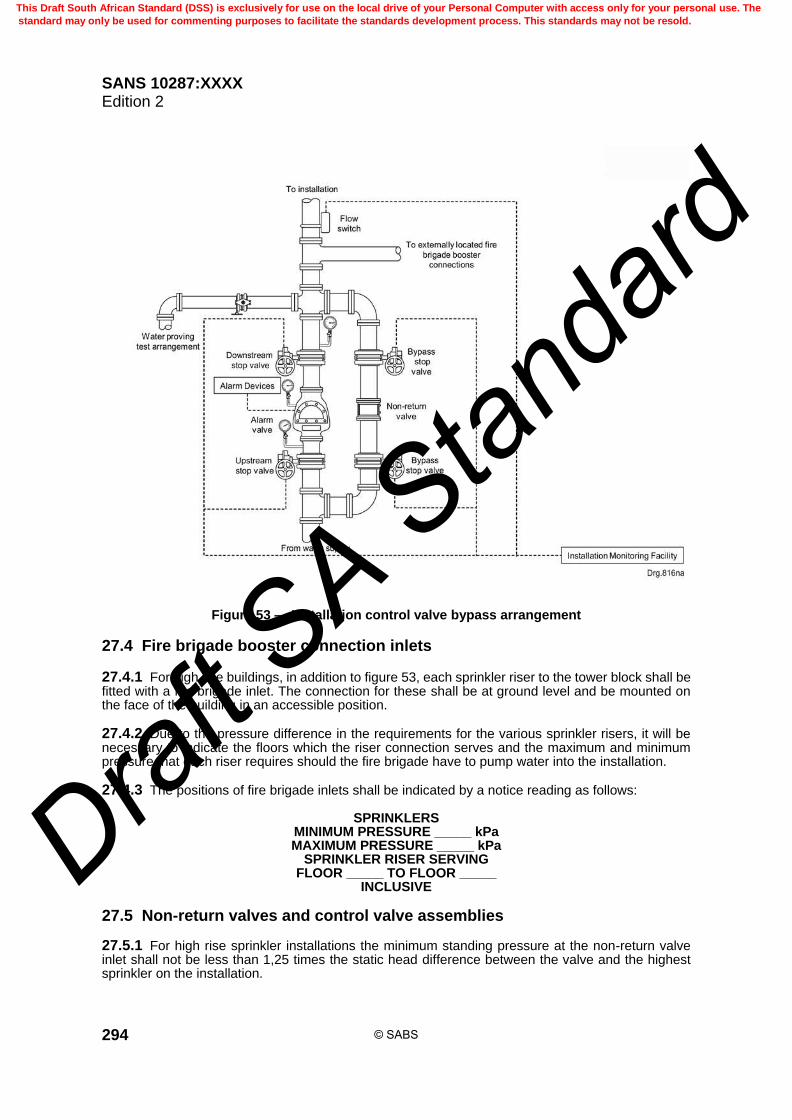
SANS 10287:XXXX Edition 2
294
Figure 53 — Installation control valve bypass arrangement
27.4 Fire brigade booster connection inlets 27.4.1 For high rise buildings, in addition to figure 53, each sprinkler riser to the tower block shall be fitted with a fire brigade inlet. The connection for these shall be at ground level and be mounted on the face of the building in an accessible position. 27.4.2 Due to the pressure difference in the requirements for the various sprinkler risers, it will be necessary to indicate the floors which the riser connection serves and the maximum and minimum pressure that each riser requires should the fire brigade have to pump water into the installation. 27.4.3 The positions of fire brigade inlets shall be indicated by a notice reading as follows:
SPRINKLERS MINIMUM PRESSURE _____ kPa MAXIMUM PRESSURE _____ kPa
SPRINKLER RISER SERVING FLOOR _____ TO FLOOR _____
INCLUSIVE
27.5 Non-return valves and control valve assemblies 27.5.1 For high rise sprinkler installations the minimum standing pressure at the non-return valve inlet shall not be less than 1,25 times the static head difference between the valve and the highest sprinkler on the installation.
© SABS
This Draft South African Standard (DSS) is exclusively for use on the local drive of your Personal Computer with access only for your personal use. The
standard may only be used for commenting purposes to facilitate the standards development process. This standards may not be resold.
Draft S
A Stan
dard

SANS 10287:XXXX Edition 2
295
27.5.2 Non-return valves controlling installation flow shall operate correctly with a ratio of service pressure to installation pressure not exceeding 1,16:1, as measured by valve lift and pressure equalization upstream of the non-return valve.
27.6 Water flow alarm switches 27.6.1 At least one water flow alarm switch which is approved shall be incorporated in the sprinkler system pipework on each floor above the alarm valves, to indicate on a central panel the particular floor on which the sprinkler system is operating. 27.6.2 A bypass arrangement consisting of an isolating valve and a non-return valve shall be fitted immediately upstream of the water flow alarm switch and an isolating valve on the downstream side of the water flow alarm switch. 27.6.3 A bypass arrangement locked in the closed position of not less than the diameter of the distribution pipe feeding the area under consideration shall be fitted. 27.6.4 A 25 mm stop valve shall be fitted not less than 2 diameters immediately downstream of each water flow alarm switch in order to periodically test the switches. The test valve shall be accessible at hand level and will be normally locked closed. The test pipe shall incorporate a sight glass downstream of the test valve which shall feed into an adequately sized common drain running through the height of the building. 27.6.5 Before more than one water flow alarm switch is installed into the sprinkler system on one floor, care shall be taken in positioning the flow switches, such that the activation of one flow switch does not affect another, due to the turbulence caused by the flow of the water. 27.6.6 The central control panel shall ideally be situated on the ground floor in the foyer and where there is 24 h surveillance. 27.6.7 A repeater panel is required to be situated in the caretaker's or security companies' office. 27.6.8 The central control panel shall comply with this standard pertaining to the construction of pump drive controller as shall the panel and battery details.
27.7 Zoning of life safety installations
27.7.1 Zoning is mandatory for wet pipe Ordinary Hazard high rise installations and strongly recommended for all other life safety structures based on suitability.
27.7.2 The number of sprinklers controlled by any one set of installation control valve set shall not exceed 10 000 based on the following restrictions: a) the number of sprinklers to be controlled by any one set of wet installation control valves on any
one floor shall not exceed 1,000; b) the installation shall be zoned in accordance with the requirements of this standard using the life
safety bypass arrangement; c) car parks and areas involving the unloading and storage of goods shall be on a separate un-zoned
installation; and d) the building shall be fully sprinkler protected throughout on all floors.
27.7.3 No zone shall a) include more than 500 sprinklers, and
© SABS
This Draft South African Standard (DSS) is exclusively for use on the local drive of your Personal Computer with access only for your personal use. The
standard may only be used for commenting purposes to facilitate the standards development process. This standards may not be resold.
Draft S
A Stan
dard

SANS 10287:XXXX Edition 2
296
b) cover more than one floor level which may, however, include a mezzanine floor no greater than 100 m2.
27.7.4 Each zone shall be independently controlled by a single zone life safety bypass arrangement as shown in figure 54 which shall be installed in a readily accessible position at the floor level of the zone it controls.
27.7.5 Each valve shall be secured open and be labelled to identify the area of protection it controls.
27.7.6 Each zone shall be fitted with a valve of not less than 25 mm nominal diameter, either on the end of the distribution pipe which is hydraulically most unfavourable from the water supply or on the end of each distribution pipe as appropriate. The valve outlet shall be taken to a suitable drainage point.
27.7.7 Zoned sprinkler installations shall be provided with tamper-proof devices to monitor the status of a) each stop valve’s position either fully open or not fully open including the subsidiary stop valves
which may be capable of interrupting the flow of water to the sprinklers, b) water flow into each zone immediately downstream of each zone subsidiary stop valve to indicate
the operation of each zone by means of a water flow alarm switch capable of detecting a flow equal to or greater than that of a single sprinkler head, and
c) water flow through each main installation control valve assembly.
27.7.8 Permanent test and drainage facilities shall be provided immediately downstream of the water flow alarm switch on each zone.
27.7.9 The test facility shall simulate operation of any single sprinkler head. Adequate provision shall be made for the disposal of the waste water.
27.7.10 The monitoring devices shall be electrically connected to a control and initiating panel installed at an accessible location on the premises where the following indications and warnings shall be given: a) green visual indicators to indicate that each monitored stop valve is in its correct operational
position; b) audible devices and amber visual indicators to indicate that one or more control valve sets are not
fully open; c) audible devices and amber visual indicators to indicate that one or more subsidiary stop valves are
not fully open; d) audible devices and amber visual indicators to indicate that the static pressure in any trunk main
supplying the system has fallen to a value of 50 kPa or more below the normal static pressure; e) audible devices and red visual indicators to indicate that water is flowing into the installation; and f) audible devices and red visual indicators to indicate that water is flowing into one or more zones. 27.7.11 Facilities shall be provided at the indicator panel for silencing the audible alarms but the visual indicators shall continue to operate until the installation is restored to its normal standby condition.
© SABS
This Draft South African Standard (DSS) is exclusively for use on the local drive of your Personal Computer with access only for your personal use. The
standard may only be used for commenting purposes to facilitate the standards development process. This standards may not be resold.
Draft S
A Stan
dard

SANS 10287:XXXX Edition 2
297
27.7.12 Fire and fault signals shall be indicated at a permanently manned location. 27.7.13 Any change in the panel alarm or fault indication after the audible alarm has been silenced shall cause it to resume sounding until it is again silenced or the panel reset to the normal standby condition. 27.7.14 Where installations are arranged in zones, the site block plan shall additionally indicate the positions of the zone control valves.
Figure 54 — Sprinkler high rise floor level life safety bypass arrangement 27.8 Special considerations 27.8.1 Fast response sprinklers shall be used for all life safety applications. 27.8.2 Only one zone and the smallest part necessary of a multi-zone installation shall be shut down at one time and for the minimum time necessary. 27.8.3 The partial or complete shutdown of a life safety sprinkler installation shall be avoided wherever possible. 27.8.4 When a zone is charged or recharged with water after draining, the flushing valves shall be used to check that water is available in all zones. 27.9 Special considerations — Hotels and high rise buildings 27.9.1 Garages parking levels 27.9.1.1 Sprinkler protection is required in all parking levels that are within the high rise footprint or communicate with the sprinkler protected structure. 27.9.1.2 Where sprinkler protection is provided, standard response sprinklers shall be used and the assumed maximum area of operation may be reduced to 144 m2.
© SABS
This Draft South African Standard (DSS) is exclusively for use on the local drive of your Personal Computer with access only for your personal use. The
standard may only be used for commenting purposes to facilitate the standards development process. This standards may not be resold.
Draft S
A Stan
dard

SANS 10287:XXXX Edition 2
298
27.9.2 Utility spaces Complete sprinkler protection in electrical, mechanical, telephone and computer rooms is required.
27.9.3 Loading docks and truck bays Full sprinkler protection within loading docks and truck bays is required.
27.9.4 Freezers and cold rooms Freezers and cold rooms shall be protected. When the temperature is likely to drop or is maintained at or below 5o C, dry pendent droppers off a wet sprinkler system can be used.
27.9.5 Guestroom bathrooms for hotels 27.9.5.1 Sprinklers are not required if the bathroom is less than 5,0 m2. 27.9.5.2 Regardless of bathroom area, sprinklers are required when combustible baths or shower or bath surrounds such as plastic or fibreglass enclosures are used.
27.9.6 Closets, wardrobes, cupboards and pantries 27.9.6.1 Sprinklers are not required in clothes closets, linen closets, wardrobes, cupboards and pantries within a hotel guestroom where the area of the space does not exceed 2,5 m2. 27.9.6.2 Closets and pantries with washer, dryer, water heater, mechanical or electrical equipment within them require sprinkler protection.
27.10 Multi-stage pumps for high rise buildings
27.10.1 For installations where the static head and corresponding performance characteristic of 1 200 kPa is exceeded, multi-stage pumps which is approved shall be used.
27.10.2 Where the protection of a building exceeds 45,0 m in height as would be the case for high rise structures, approved multi-stage, multi-take-off pumps shall be used.
27.10.3 The protection shall be subdivided into installations, each serving a set of floors where the height of the sprinklers on the upper floor of the set above the sprinklers on the lower floor does not exceed 45,0 m.
27.10.4 The pump shall be of robust and compact design built up from a number of stages held together by body bolts between two end covers. The end covers shall incorporate the suction and final delivery branches respectively.
27.10.5 For each intermediate pressure take-off point, an intermediate flanged delivery branch shall be fitted.
27.10.6 Each effective live stage shall contain guide passages to carry the water being pumped from the delivery of one impeller to the eye of the next impeller.
27.10.7 A hydraulic balance valve or disc, or alternatively a suitable thrust bearing of the thrust pad design, shall be fitted to absorb the hydraulic thrusts.
27.10.8 Where the pump parts in column 1 of table 107 are used, the materials given in column 2 of table 107 shall apply:
© SABS
This Draft South African Standard (DSS) is exclusively for use on the local drive of your Personal Computer with access only for your personal use. The
standard may only be used for commenting purposes to facilitate the standards development process. This standards may not be resold.
Draft S
A Stan
dard

SANS 10287:XXXX Edition 2
299
Table 107 — Material composition of multi-stage pumps
1 2
Pump part Material
Balance valve or disc Bronze
Bearings Ball/Roller or sleeve type
Casing neck rings Bronze
Casing neck bushes Bronze
End covers Cast iron
Glands Bronze
Gland packing High grade graphite cotton
Guide passages of diffusers Bronze
Lantern rings Bronze
Impellers Bronze
Middle bodies Cast iron
Partition or division plates Cast iron
Shaft EN 8 Steel
Sleeves Bronze
Thrust bearing Fitting pad double thrust assembly
27.10.9 Cast iron shall not be used for any wetted rotating component or stationary part in close running contact with the rotating member. Pumps constructed other than as above shall have the design features suited for sprinkler use.
27.10.10 Figures 55, 56 and 57 indicate different layouts of water supplies for high rise installations.
© SABS
This Draft South African Standard (DSS) is exclusively for use on the local drive of your Personal Computer with access only for your personal use. The
standard may only be used for commenting purposes to facilitate the standards development process. This standards may not be resold.
Draft S
A Stan
dard

SANS 10287:XXXX Edition 2
300
Figure 55 — Typical high rise building sprinkler layout
© SABS
This Draft South African Standard (DSS) is exclusively for use on the local drive of your Personal Computer with access only for your personal use. The
standard may only be used for commenting purposes to facilitate the standards development process. This standards may not be resold.
Draft S
A Stan
dard

SANS 10287:XXXX Edition 2
301
Figure 56 — Progressive valve layout for a high rise building
© SABS
This Draft South African Standard (DSS) is exclusively for use on the local drive of your Personal Computer with access only for your personal use. The
standard may only be used for commenting purposes to facilitate the standards development process. This standards may not be resold.
Draft S
A Stan
dard

SANS 10287:XXXX Edition 2
302
Figure 57 — Typical high rise building layout with gravity tank and pumps
© SABS
This Draft South African Standard (DSS) is exclusively for use on the local drive of your Personal Computer with access only for your personal use. The
standard may only be used for commenting purposes to facilitate the standards development process. This standards may not be resold.
Draft S
A Stan
dard

SANS 10287:XXXX Edition 2
303
27.11 Centrifugal horizontal shaft design pumps
27.11.1 Approved pumps connected in series may be used as an alternative provided the output pressure can be adequately controlled.
27.11.2 The performance characteristic of the pump(s) shall be such that the pressure falls progressively with the rate of demand, so whilst being capable of providing the rate of flow and pressure required at the highest and most unfavourable parts of each floor, the output will be so controlled that the rate of discharge at the lowest level in areas close to the control valves on any particular floor will not overload the pump set.
27.11.3 Where the height of the building exceeds the capabilities of the sprinkler pumps situated in the lower level of the building, consideration shall be given to additional sprinkler pumps with suction tanks situated at intermediate levels of the building.
27.11.4 Pumps used for life safety applications shall be provided with a positive suction.
27.11.5 The closed outlet valve pressure at the pump, under installed conditions, may exceed 1 200 kPa, but shall be within the design limits of the pump and associated pipework.
27.11.6 Each pump shall have its own controller, which shall be specifically designed for sprinkler fire pump service. The pump drive controller shall comply with this standard.
27.11.7 The pump room shall have its own annunciator panel, audible and visual signalling devices and a repeater panel, all of which shall be approved for sprinkler use.
27.11.8 The pump house annunciator and pump house repeater panel shall comply with this standard.
27.11.9 The pump house repeater panel shall also be capable of monitoring the circuits of all water flow alarm switches.
28 Installation calculation
28.1 General
28.1.1 All sprinkler systems shall be hydraulically calculated in accordance with this standard.
28.1.2 Pre-calculated pipe size tables shall not be used.
28.1.3 Combined pre-calculated and fully hydraulically calculated systems shall not be used.
28.1.4 Combined systems of differing standards are not permitted.
28.2 Calculation accuracy
28.2.1 Calculations shall be carried out in the units and to the accuracy given in table 108.
28.2.2 At every hydraulic junction where flows divide or conjoin a) the total flow into the junction shall equal the total flow out of the junction to an accuracy of 0,1 L
per minute, and b) the pressure shall balance to within 0,1 kPa.
© SABS
This Draft South African Standard (DSS) is exclusively for use on the local drive of your Personal Computer with access only for your personal use. The
standard may only be used for commenting purposes to facilitate the standards development process. This standards may not be resold.
Draft S
A Stan
dard

SANS 10287:XXXX Edition 2
304
Table 108 — Calculation accuracy
1 2 3
Quantity Unit Accuracy
Design density mm/min 0,1
Flow in calculations L/min 0,001
Pressure in calculations kPa 0,001
Velocity m/s 0,001
Pipe elevation m 0,001
Pipe length m 0,001
Equivalent pipe length m 0,001
Area m2 0,01
Length m 0,01
28.3 Assumed maximum area of operation
28.3.1 The assumed maximum area of operation is deemed to be the maximum area, expressed in square metres and is the assumed maximum area, over which it is assumed for design purposes, that sprinklers will operate in a fire.
28.3.2 The assumed maximum area of operation (AMAO), is that specified in this standard or reached by agreement between all parties where special circumstances may prevail.
28.4 Hydraulically unfavourable assumed maximum area of operation
28.4.1 For the purpose of determining the hydraulically most unfavourable position the assumed maximum area of operation shall be located in turn in the hydraulically most unfavourable position on each distribution pipe, or between distribution pipes where they are connected together by range pipes, in the installation; unless it is obvious that an array is similar to another array under consideration and is hydraulically nearer the water supply.
28.4.2 Consideration shall be given to any changes in sprinkler spacing, elevation, range centres, sprinkler orifice and pipe sizes.
28.4.3 Continuous operation of the assumed maximum area of operation at the hydraulically most unfavourable position in the installation creates the most adverse pressure condition. This adverse pressure condition shall be used to establish the minimum sprinkler discharge pressures (Pmax), and the required density averaged over any four adjacent sprinklers, as defined in 28.9.
28.5 Hydraulically most favourable position
28.5.1 For the purpose of determining the correct position, the assumed maximum area of operation shall be located either at the hydraulically most favourable position on each distribution pipe, or between distribution pipes where they are connected by range pipes, that may represent the hydraulically most favourable position for the installation. See figures 58, 59 and 60.
28.5.2 Continuous operation of the assumed maximum area of operation at the hydraulically most favourable position in the installation, when extrapolated onto the water supply pressure/flow characteristic will create the maximum flow load condition (Qmax), at a specified pressure, which shall be used to determine the water supply requirements.
© SABS
This Draft South African Standard (DSS) is exclusively for use on the local drive of your Personal Computer with access only for your personal use. The
standard may only be used for commenting purposes to facilitate the standards development process. This standards may not be resold.
Draft S
A Stan
dard
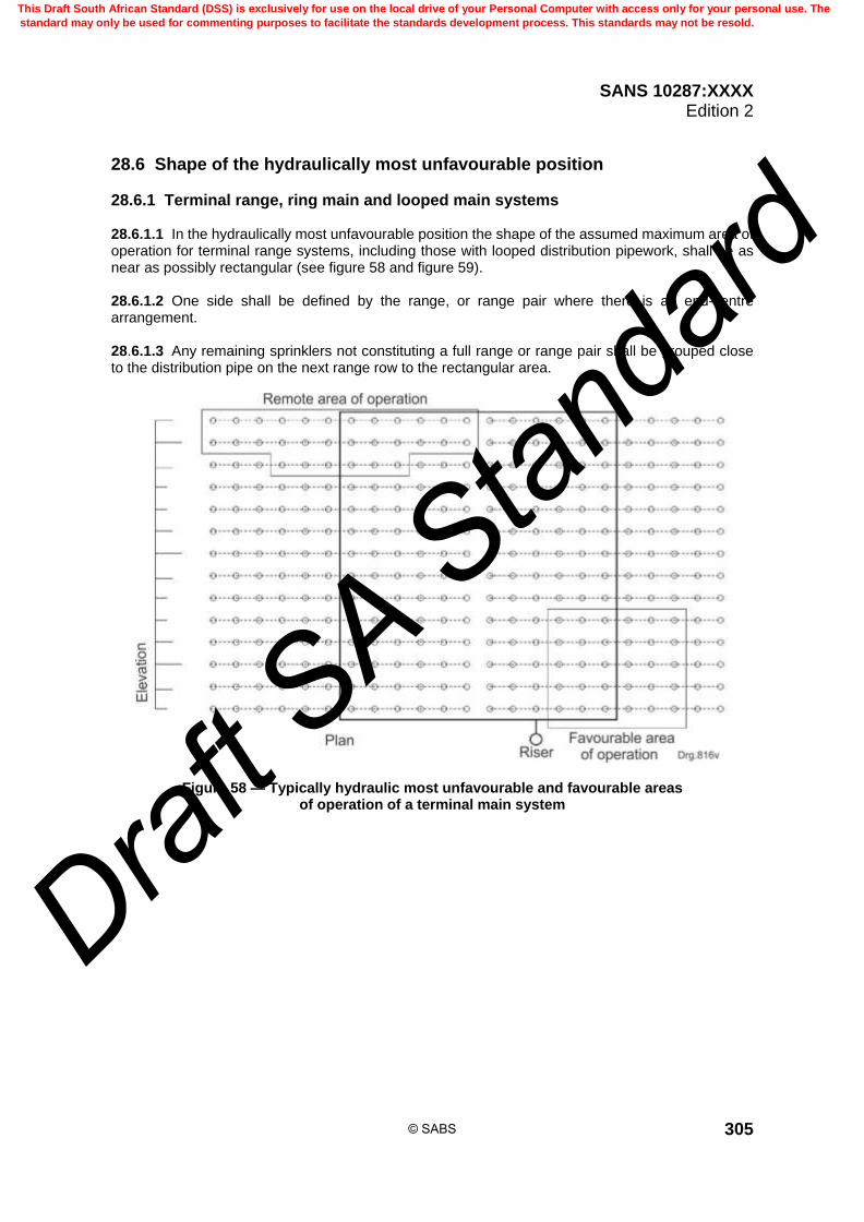
SANS 10287:XXXX Edition 2
305
28.6 Shape of the hydraulically most unfavourable position
28.6.1 Terminal range, ring main and looped main systems 28.6.1.1 In the hydraulically most unfavourable position the shape of the assumed maximum area of operation for terminal range systems, including those with looped distribution pipework, shall be as near as possibly rectangular (see figure 58 and figure 59). 28.6.1.2 One side shall be defined by the range, or range pair where there is an end-centre arrangement. 28.6.1.3 Any remaining sprinklers not constituting a full range or range pair shall be grouped close to the distribution pipe on the next range row to the rectangular area.
Figure 58 — Typically hydraulic most unfavourable and favourable areas of operation of a terminal main system
© SABS
This Draft South African Standard (DSS) is exclusively for use on the local drive of your Personal Computer with access only for your personal use. The
standard may only be used for commenting purposes to facilitate the standards development process. This standards may not be resold.
Draft S
A Stan
dard

SANS 10287:XXXX Edition 2
306
Figure 59 — Typically hydraulic most unfavourable and favourable areas of operation of a ring main system
28.6.2 Gridded systems branch lines 28.6.2.1 Gridded systems may not be installed on the dry pipe system. Where ranges run parallel to the ridge roof with a slope greater than 6o, or along bays formed by beams greater than 1,0 m deep, the shape of the assumed maximum area of operation for the hydraulically most unfavourable position shall be rectangular with a length (L), greater than or equal to 2 times the square root of the area (A). 28.6.2.2 The following method shall be used to determine the number of sprinklers deemed to be in simultaneous operation on a branch line. Where L has a remainder equal to or greater than 0,5, the next integer shall be used to determine the number in operation. Where L has a remainder less than 0,5, the actual integer is used to determine the number in operation. See figure 60.
L ≥ S
A 2
where L is the dimensions of AMAO parallel to range pipes, in metres (m); A is the assumed maximum area of operation, in metres squared (m2); S is the average distance between all sprinklers on a branch line under consideration, in
metres (m). 28.6.2.3 In all other cases the shape of the assumed maximum area of operation shall be rectangular with a length, (L), greater or equal to 1,2 times the square root of the area, A.
© SABS
This Draft South African Standard (DSS) is exclusively for use on the local drive of your Personal Computer with access only for your personal use. The
standard may only be used for commenting purposes to facilitate the standards development process. This standards may not be resold.
Draft S
A Stan
dard

SANS 10287:XXXX Edition 2
307
28.6.2.4 The following method shall be used to determine the number of sprinklers deemed to be in simultaneous operation on a branch line. Where L has a remainder equal to or greater than 0,5, the next higher integer shall be used to determine the number in operation. Where L has a remainder less than 0,5, the actual integer is used to determine the number in operation.
L ≥ S
A1,2
where
L is the dimensions of AMAO parallel to range pipes, in metres (m); A is the assumed maximum area of operation, in square metres (m2); S is the average distance between all sprinklers on a branch line under consideration, in
metres (m). 28.6.2.5 For the purpose of this subclause all measurements shall be made in the horizontal plane, including installations with sloping pipework.
Figure 60 — Typically hydraulic most unfavourable and favourable areas of operation of a grid system
28.7 Shape of the hydraulically most favourable position
28.7.1 Terminal range systems 28.7.1.1 In the hydraulically most favourable position the shape of the assumed maximum area of operation for terminal range systems including those with looped distribution pipework shall be as close as possible to a square, subject to the limitation that it shall, where possible, involve sprinklers on one distribution pipe only (see figure 58).
© SABS
This Draft South African Standard (DSS) is exclusively for use on the local drive of your Personal Computer with access only for your personal use. The
standard may only be used for commenting purposes to facilitate the standards development process. This standards may not be resold.
Draft S
A Stan
dard

SANS 10287:XXXX Edition 2
308
28.7.1.2 The number of sprinklers calculated to be operating on ranges, or range pairs in end centre systems, shall be located on each range or range pair at the hydraulically most favourable position. Any remaining sprinklers not constituting a full range or range pair shall be located on the next range row at the hydraulically closest positions. 28.7.1.3 Where the requirement in 28.7.1.2 is not feasible, agreement between all parties shall be reached.
28.7.2 Gridded systems 28.7.2.1 The shape of the assumed maximum area of operation for the hydraulically most favourable position shall be as close as possible to a square (see figure 60). 28.7.2.2 The number of sprinklers calculated to be operating shall be located on ranges at the hydraulically most favourable position. If there are a remaining number of sprinklers, they shall be located on the next range row at the hydraulically closest positions.
28.8 Proof of correct position of assumed maximum area of operation
28.8.1 Proof will be required that the position of the hydraulically most favourable and unfavourable assumed areas of operation have been established regardless of the type of supply.
28.8.2 Such proof may entail displacing the assumed maximum area of operation by one sprinkler in each direction along ranges pipes or by one range pipe in each direction along distribution pipes (or both).
28.9 Density of discharge
28.9.1 The density of discharge is expressed in millimetres per minute per square metre of floor area.
28.9.2 The density of discharge between any four adjacent sprinklers in a square or rectangle, (or parallelogram where the sprinklers are staggered), shall be assumed to be the sum of the total flow from the four sprinklers, (in litres per minute), divided by 4 times the square, rectangle or parallelogram of the floor area enclosed by the sprinklers.
28.9.3 The calculated density of discharge from any such four adjacent sprinklers within any maximum assumed area of operation with all sprinklers simultaneously discharging shall not be less than the design density of discharge required.
28.10 Actual spacing
28.10.1 The area covered by a sprinkler not on the operating area boundary shall be a square or rectangle centred on the sprinkler and extending along the range to the midpoints between the sprinkler and adjacent sprinklers on the range and, normal to the range, to the midpoints between the sprinkler and adjacent ranges.
28.10.2 The area covered by a sprinkler on the boundary shall be a square or rectangle extending, normal to the boundary, from the boundary to the midway point between the sprinkler and the adjacent sprinkler or range and, parallel to the boundary, from the sprinkler to the midway points between adjacent sprinklers or ranges.
© SABS
This Draft South African Standard (DSS) is exclusively for use on the local drive of your Personal Computer with access only for your personal use. The
standard may only be used for commenting purposes to facilitate the standards development process. This standards may not be resold.
Draft S
A Stan
dard

SANS 10287:XXXX Edition 2
309
28.10.3 The minimum discharge from any sprinkler within the protected area shall not be less than the design density of discharge multiplied by the maximum area covered by any one sprinkler determined as follows: A = S × D
where A is the design area per sprinkler, in square metres (m2);
S is the greater distance between two adjacent sprinklers along a range pipe or twice the
distance to the wall running parallel to the range pipe, in metres (m); D is the greater distance between two adjacent sprinklers on adjacent range pipes or twice
the distance between the last sprinkler perpendicular to the wall, in metres (m).
28.11 Nominal spacing 28.11.1 The nominal spacing of a sprinkler installation is determined by the following method:
S = N
A
where S is the average spacing of the sprinklers within the area (A) under consideration; A is the area under consideration, in square metres (m2); N is the number of sprinklers within the area (A) under consideration. 28.11.2 The area under consideration shall encompass a) a single hazard classification, and b) a single design density of discharge. 28.11.3 Unless the assumed maximum number of sprinklers in operation is given, the nominal spacing is used to determine the number of sprinklers in operation. 28.12 Number of sprinklers in operation 28.12.1 Sprinkler systems that use an assumed maximum number of sprinklers in operation such as the ESFR sprinkler have a predefined number of sprinklers in operation and unless otherwise noted, that number in accordance with this standard shall be used. 28.12.2 The following equation shall be used in order to determine the number of sprinklers deemed to be in simultaneous operation:
N = S
A + R
where N is the number of sprinklers deemed to be in simultaneous operation; A is the assumed maximum area of operation, in square metres (m2); S is the nominal spacing as determined in this standard, in metres (m); R is the number of sprinklers located beneath obstructions in the assumed maximum area
of operation.
© SABS
This Draft South African Standard (DSS) is exclusively for use on the local drive of your Personal Computer with access only for your personal use. The
standard may only be used for commenting purposes to facilitate the standards development process. This standards may not be resold.
Draft S
A Stan
dard

SANS 10287:XXXX Edition 2
310
28.13 Minimum flow
28.13.1 The minimum flow required at any sprinkler, unless otherwise specified in this standard, deemed to be in simultaneous operation within the assumed maximum area of operation shall be derived from the actual spacing of the sprinklers as defined in this standard.
28.13.2 The flow through a sprinkler head is determined as follows:
Q = K × P where Q is the flow, in litres per minute (L/min); K is the nominal K-factor of the sprinkler (metric); P is the pressure, in kilopascals (kPa).
28.13.3 The flow from an individual sprinkler within the area of operation shall be adjusted as determined by the pressure available at that sprinkler.
28.14 Minimum pressure
28.14.1 The minimum operating pressure of a sprinkler shall not be less than 50 kPa unless the application for a specific listing has specified a pressure for the sprinkler, the higher pressure shall be used. The minimum pressure required shall be determined as follows:
P =
2
K
Q
where P is the pressure, in kilopascals (kPa); Q is the flow, in litres per minute (L/min); K is the nominal K-factor of the sprinkler (metric).
28.14.2 The pressure at any sprinkler with all sprinklers discharging simultaneously within any appropriate assumed maximum area of operation shall not be less than that stated in table 109.
Table 109 — Minimum discharge pressure
1 2
Nominal pipe thread Minimum operating pressure
mm kPa
15a 50
15b 50
20 50
a Ordinary hazard occupancies 35 kPa.
b High hazard occupancies 50 kPa.
© SABS
This Draft South African Standard (DSS) is exclusively for use on the local drive of your Personal Computer with access only for your personal use. The
standard may only be used for commenting purposes to facilitate the standards development process. This standards may not be resold.
Draft S
A Stan
dard
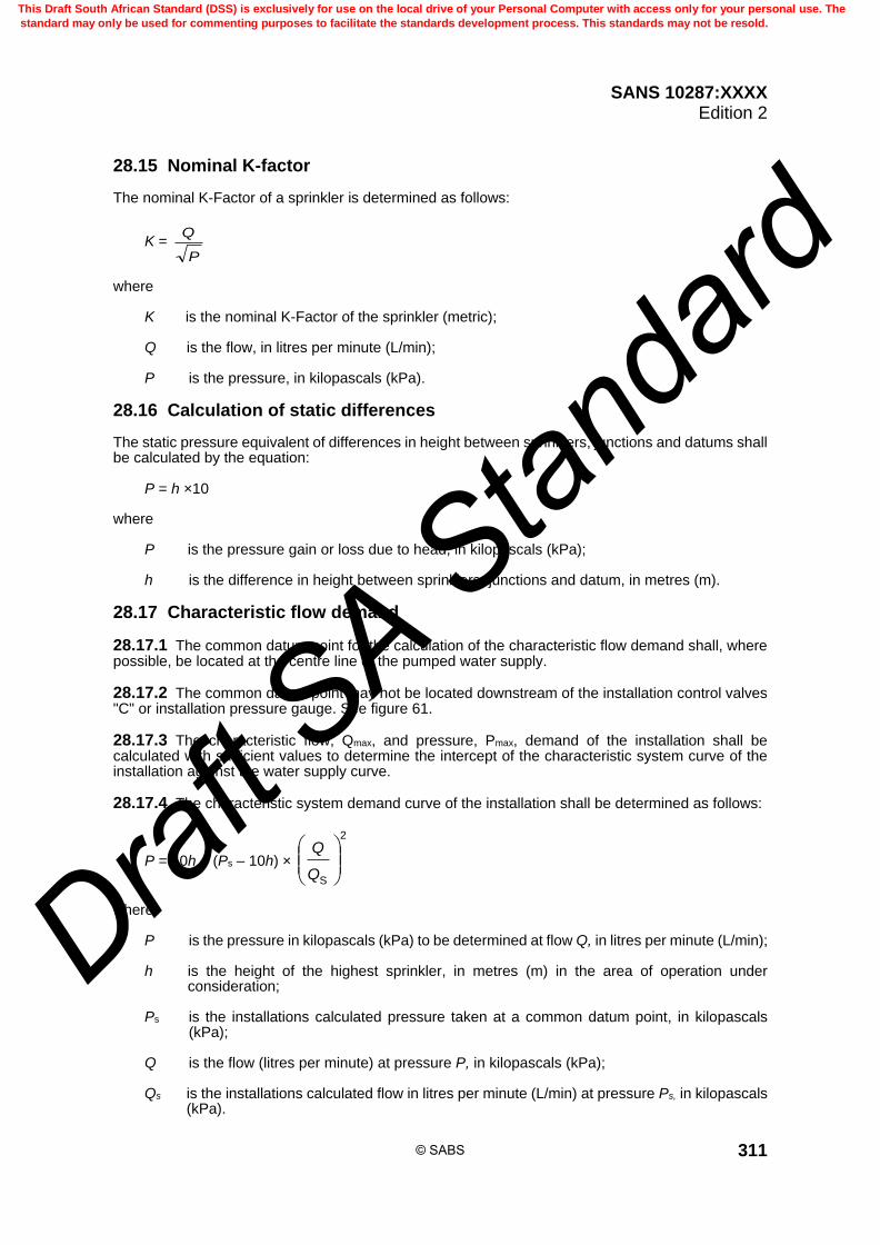
SANS 10287:XXXX Edition 2
311
28.15 Nominal K-factor The nominal K-Factor of a sprinkler is determined as follows:
K = P
Q
where K is the nominal K-Factor of the sprinkler (metric); Q is the flow, in litres per minute (L/min); P is the pressure, in kilopascals (kPa).
28.16 Calculation of static differences The static pressure equivalent of differences in height between sprinklers, junctions and datums shall be calculated by the equation: P = h ×10
where P is the pressure gain or loss due to head, in kilopascals (kPa); h is the difference in height between sprinklers, junctions and datum, in metres (m).
28.17 Characteristic flow demand 28.17.1 The common datum point for the calculation of the characteristic flow demand shall, where possible, be located at the centre line of the pumped water supply. 28.17.2 The common datum point may not be located downstream of the installation control valves "C" or installation pressure gauge. See figure 61. 28.17.3 The characteristic flow, Qmax, and pressure, Pmax, demand of the installation shall be calculated with sufficient values to determine the intercept of the characteristic system curve of the installation against the water supply curve. 28.17.4 The characteristic system demand curve of the installation shall be determined as follows:
P = 10h + (Ps – 10h) ×
2
S
Q
Q
where P is the pressure in kilopascals (kPa) to be determined at flow Q, in litres per minute (L/min);
h is the height of the highest sprinkler, in metres (m) in the area of operation under consideration;
Ps is the installations calculated pressure taken at a common datum point, in kilopascals
(kPa); Q is the flow (litres per minute) at pressure P, in kilopascals (kPa);
Qs is the installations calculated flow in litres per minute (L/min) at pressure Ps, in kilopascals (kPa).
© SABS
This Draft South African Standard (DSS) is exclusively for use on the local drive of your Personal Computer with access only for your personal use. The
standard may only be used for commenting purposes to facilitate the standards development process. This standards may not be resold.
Draft S
A Stan
dard

SANS 10287:XXXX Edition 2
312
28.17.5 Qmax and Pmax are representative of the total flow and pressure requirement of the sprinkler installation. This shall include, but is not necessarily limited to a) the roof or ceiling level sprinkler operation in accordance with the required design density of
discharge to the assumed maximum area of operation, and b) as determined by this standard, the simultaneous operation of any number of sprinkler located at
or in
1) rack,
2) shelf,
3) mezzanine, or
4) sprinklers beneath the assumed maximum area of operation.
Figure 61 — Typical pump and system curves
28.18 Calculation of friction and pressure losses
28.18.1 Calculations of pipe friction losses shall not be less than those derived from the Hazen-Williams formula as follows:
P = 6,05 × 107 ×
4,871,85
1,85
DC
lQ
where P is the pressure loss over the length of the pipe, in kilopascals (kPa); Q is the flow through the pipe, in litres per minute (L/min);
© SABS
This Draft South African Standard (DSS) is exclusively for use on the local drive of your Personal Computer with access only for your personal use. The
standard may only be used for commenting purposes to facilitate the standards development process. This standards may not be resold.
Draft S
A Stan
dard

SANS 10287:XXXX Edition 2
313
l is the length of the pipe, in metres (m); C is the Hazen-Williams roughness coefficient (see table 110); D is the mean nominal inside diameter of the pipe, in millimetres (mm).
28.18.2 The following equation can be used for pipes with the applicable "K" value as given in the tables 111, 112, 113 and 114. P = Q 1.85 × K × L where P is the pressure loss over the length of the pipe, in kilopascals (kPa); Q is the flow through the pipe, in litres per minute (L/min); K the constant for the type of pipe contemplated for use (see tables 111, 112, 113 and 114); L is the length of the pipe, in metres (m).
Table 110 —"C" values for various types of pipes
1 2
Type of pipe Value of "C"
Cast iron 100
Ductile iron 110
Galvanized steel 120
Mild steel 120
Cement lined cast iron 130
Spun cement 130
Asbestos cement 140
Copper 140
HDPE (Not recommended for sprinkler use) 140
PVC-U 140
Reinforced glass fibre 140
Stainless steel 140
CPVC 150
NOTE The list is not exhaustive.
© SABS
This Draft South African Standard (DSS) is exclusively for use on the local drive of your Personal Computer with access only for your personal use. The
standard may only be used for commenting purposes to facilitate the standards development process. This standards may not be resold.
Draft S
A Stan
dard

SANS 10287:XXXX Edition 2
314
Table 111 — Pipe mean diameters and value of "K" steel pipe
1 2 3 4 5 6 7 8 9
Nominal diameter of pipe
Not galvanized medium
(see SANS 62-1)
Not galvanized heavy
(see SANS 719)
Galvanized medium
(see SANS 62-1)
Galvanized heavy
(see SANS 719)
Mean diameter Value of K
Mean diameter Value of K
Mean diameter Value of K
Mean diameter Value of K
mm mm mm mm mm
20 21,63 2,71 × 10 -3 20,42 3,60 × 10 -3 21,46 2,82 × 10 -3 20,24 3,75 × 10 -3
25 27,31 8,72 × 10 -4 25,68 1,18 × 10 -3 27,14 8,99 × 10 -4 25,51 1,22 × 10 -3
32 35,97 2,28 × 10 -4 34,34 2,86 × 10 -4 35,80 2,33 × 10 -4 34,17 2,93 × 10 -4
40 41,86 1,09 × 10 -4 40,23 1,32 × 10 -4 41,69 1,11 × 10 -4 40,16 1,33 × 10 -4
50 52,98 3,46 × 10 -5 51,36 4,02 × 10 -5 52,81 3,51 × 10 -5 51,19 4,09 × 10 -5
65 68,67 9,78 × 10 -6 67,04 1,10 × 10 -5 68,50 9,90 × 10 -6 68,87 1,11 × 10 -5
80 80,68 4,46 × 10 -6 79,06 4,92 × 10 -6 80,51 4,51 × 10 -6 78,89 4,97 × 10 -6
100 105,15 1,23 × 10 -6 103,31 1,34 × 10 -6 104,97 1,24 × 10 -6 103,14 1,35 × 10 -6
150 155,32 1,84 × 10 -7 154,30 1,90 × 10 -7 155,15 1,85 × 10 -7 154,13 1,91 × 10 -7
200 – – 208,30 4,40 × 10 -8 – – 208,13 4,42 × 10 -8
Table 112 — Pipe mean diameters and value of "K" steel pipe
1 2 3 4 5
Nominal diameter of pipe
Not galvanized heavy 4,5 mm wall thickness
(see SANS 719)
Galvanized heavy 4,5 mm wall thickness
(see SANS 719)
Mean diameter Value of K
Mean diameter Value of K
mm mm mm
200 210,10 4,22 × 10 -8 209,93 4,23 × 10 -8
250 264,00 1,39 × 10 -8 263,83 1,39 × 10 -8
300 314,9 5,88 × 10 -9 314,73 5,89 × 10 -9
350 346,60 3,68 × 10 -9 346,43 3,69 × 10 -9
400 397,50 1,89 × 10 -9 397,33 1,89 × 10 -9
500 499,00 6,24 × 10 -10 498,83 6,26 × 10 -10
600 600,60 2,53 × 10 -10 600,43 2,54 × 10 -10
© SABS
This Draft South African Standard (DSS) is exclusively for use on the local drive of your Personal Computer with access only for your personal use. The
standard may only be used for commenting purposes to facilitate the standards development process. This standards may not be resold.
Draft S
A Stan
dard
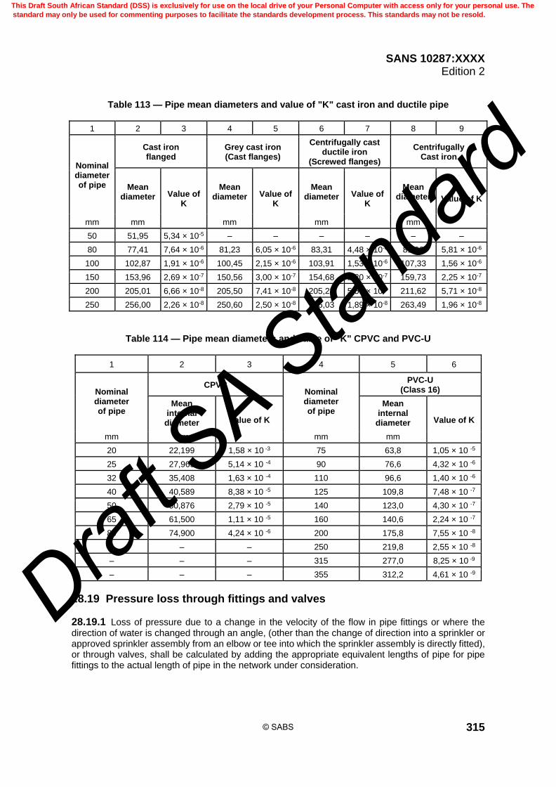
SANS 10287:XXXX Edition 2
315
Table 113 — Pipe mean diameters and value of "K" cast iron and ductile pipe
1 2 3 4 5 6 7 8 9
Nominal diameter of pipe
Cast iron flanged
Grey cast iron (Cast flanges)
Centrifugally cast ductile iron
(Screwed flanges)
Centrifugally Cast iron
Mean diameter Value of
K
Mean diameter Value of
K
Mean diameter Value of
K
Mean diameter Value of K
mm mm mm mm mm
50 51,95 5,34 × 10⁻⁵ – – – – – –
80 77,41 7,64 × 10⁻⁶ 81,23 6,05 × 10⁻⁶ 83,31 4,48 × 10⁻⁶ 81,90 5,81 × 10⁻⁶
100 102,87 1,91 × 10⁻⁶ 100,45 2,15 × 10⁻⁶ 103,91 1,53 × 10⁻⁶ 107,33 1,56 × 10⁻⁶
150 153,96 2,69 × 10⁻⁷ 150,56 3,00 × 10⁻⁷ 154,68 2,20 × 10⁻⁷ 159,73 2,25 × 10⁻⁷
200 205,01 6,66 × 10⁻⁸ 205,50 7,41 × 10⁻⁸ 205,23 5,55 × 10⁻⁸ 211,62 5,71 × 10⁻⁸
250 256,00 2,26 × 10⁻⁸ 250,60 2,50 × 10⁻⁸ 256,03 1,89 × 10⁻⁸ 263,49 1,96 × 10⁻⁸
Table 114 — Pipe mean diameters and value of "K" CPVC and PVC-U
1 2 3 4 5 6
Nominal diameter of pipe
CPVC Nominal diameter of pipe
PVC-U (Class 16)
Mean internal
diameter Value of K
Mean internal
diameter Value of K
mm mm mm mm
20 22,199 1,58 × 10 -3 75 63,8 1,05 × 10 -5
25 27,965 5,14 × 10 -4 90 76,6 4,32 × 10 -6
32 35,408 1,63 × 10 -4 110 96,6 1,40 × 10 -6
40 40,589 8,38 × 10 -5 125 109,8 7,48 × 10 -7
50 50,876 2,79 × 10 -5 140 123,0 4,30 × 10 -7
65 61,500 1,11 × 10 -5 160 140,6 2,24 × 10 -7
80 74,900 4,24 × 10 -6 200 175,8 7,55 × 10 -8
– – – 250 219,8 2,55 × 10 -8
– – – 315 277,0 8,25 × 10 -9
– – – 355 312,2 4,61 × 10 -9
28.19 Pressure loss through fittings and valves
28.19.1 Loss of pressure due to a change in the velocity of the flow in pipe fittings or where the direction of water is changed through an angle, (other than the change of direction into a sprinkler or approved sprinkler assembly from an elbow or tee into which the sprinkler assembly is directly fitted), or through valves, shall be calculated by adding the appropriate equivalent lengths of pipe for pipe fittings to the actual length of pipe in the network under consideration.
© SABS
This Draft South African Standard (DSS) is exclusively for use on the local drive of your Personal Computer with access only for your personal use. The
standard may only be used for commenting purposes to facilitate the standards development process. This standards may not be resold.
Draft S
A Stan
dard

SANS 10287:XXXX Edition 2
316
28.19.2 The equivalent length of straight pipe shall be a) taken from tables 115 or 116 or 117 as appropriate, and b) as specified by the equipment supplier.
28.19.3 Where there is a bend, tee or fitting or change in direction of flow as well as a change in diameter at the same point, the equivalent length of pipe shall be determined using the smaller diameter pipe.
28.19.4 For dry pipe sprinkler assemblies the K-factor shall be considered to apply at the entry to the sprinkler assembly. Allowances shall be made for the head gain or loss due to the length and orientation of the dry pipe.
Table 115 — Equivalent length of steel pipe fittings
1 2 3 4 5 6 7 8 9 10 11 12 13 14 15 16 17
Fittings and valves
Equivalent length of steel straight pipe for a "C" value of 120
m
Pipe diameter 20 25 32 40 50 65 80 100 150 200 250 300 350 400 500 600
mm
90o Screwed elbow (standard)
0,76 0,77 1,0 1,2 1,5 1,9 2,4 3,0 4,3 5,7 7,4 9,1 10,0 11,4 14,3 17,3
90o Welded elbow (r/d 1,5)
0,30 0,36 0,49 0,56 0,69 0,88 1,1 1,4 2,0 2,6 3,4 3,6 4,0 4,6 5,2 5,7
45o Screwed elbow (standard)
0,34 0,40 0,55 0,66 0,76 1,0 1,3 1,6 2,3 3,1 3,9 4,9 5,3 6,1 7,7 9,2
Standard screwed Tee or cross (Flow through branch)
1,3 1,5 2,1 2,4 2,9 3,8 4,8 6,1 8,6 11,0 14,0 18,2 20,0 22,9 28,7 34,5
Gate valve - straight way
– – – – 0,38 0,51 0,63 0,81 1,1 1,5 2,0 2,4 2,7 3,1 3,8 4,6
Alarm or non-return valve (Swinging type)
– – – – 2,4 3,2 3,9 5,1 7,2 9,4 12,0 15,2 16,7 19,1 21,5 23,9
Alarm or non-return valve (Mushroom type)
– – – – 12,0 19,0 19,7 25,0 35,0 47,0 62,0 72,4 79,7 91,4 114,8 138,1
Butterfly valve – – – – 2,2 2,9 3,6 4,6 6,4 8,6 9,9 10,6 11,7 13,7 15,0 17,4
Globe valve – – – – 16,0 21,0 26,0 34,0 48,0 64,0 84,0 103,0 113,5 129,6 145,8 162,6
© SABS
This Draft South African Standard (DSS) is exclusively for use on the local drive of your Personal Computer with access only for your personal use. The
standard may only be used for commenting purposes to facilitate the standards development process. This standards may not be resold.
Draft S
A Stan
dard

SANS 10287:XXXX Edition 2
317
Table 116 — Equivalent length of CPVC pipe fittings
1 2 3 4 5 6 7
Fitting Equivalent length of straight CPVC pipe
"C" factor value 150 m
Pipe diameter 25 32 40 50 65 80
mm
Tee (flow through run) 0,3 0,3 0,3 0,3 0,6 0,6
Tee (flow through branch) 1,5 1,8 2,4 3,0 3,6 4,5
90o elbow 2,1 2,4 2,7 3,3 3,6 3,9
45o elbow 0,3 0,6 0,6 0,6 0,9 1,2
Coupling 0,3 0,3 0,3 0,3 0,6 0,6
Table 117 — Equivalent lengths of PVC-U fittings
1 2 3 4 5 6 7 8 9 10 11 12
Equivalent length of straight uPVC and mPVC pipe C factor value 140
(m)
Fitting
Nominal diameter (mm)
110 125 140 160 200 250 315 355 400 450 500
Tee (flow through run)
1,0 1,1 1,3 1,5 1,8 2,3 2,9 3,2 3,7 4,1 4,6
Tee (flow through branch)
6,0 6,9 7,7 8,8 11,0 13,7 17,2 19,5 22,0 24,7 27,4
90o elbow 3,0 3,4 3,8 4,4 5,5 6,9 8,6 9,7 11,0 12,3 13,7
45o elbow 1,0 1,1 1,3 1,5 1,8 2,3 2,9 3,2 3,7 4,1 4,6
90o bend 1,0 1,1 1,3 1,5 1,8 2,3 2,9 3,2 3,7 4,1 4,6
45o bend 1,0 1,1 1,3 1,5 1,8 2,3 2,9 3,2 3,7 4,1 4,6
Coupling 3,0 3,4 3,8 4,4 5,5 6,9 8,6 9,7 11,0 12,3 13,7
Butterfly valve 13,0 14,8 16,6 19,0 23,8 29,7 37,4 42,2 47,6 53,5 59,5
Diaphragm valve 23,1 26,3 29,4 33,6 42,0 52,6 66,2 74,7 84,1 94,7 105,2
Check valve 5,0 5,7 6,4 7,3 9,1 11,4 14,4 16,2 18,3 20,6 22,9
28.19.5 These equivalent lengths (see table 117) may be converted as necessary for pipes with other "C" values by multiplying by the factors as given in table 118.
Table 118 — Equivalent lengths of fittings for differing roughness coefficients
1 2 3 4 5 6
"C" value 100 110 120 130 140
Factor 1,406 1,179 1,00 0,868 0,755
© SABS
This Draft South African Standard (DSS) is exclusively for use on the local drive of your Personal Computer with access only for your personal use. The
standard may only be used for commenting purposes to facilitate the standards development process. This standards may not be resold.
Draft S
A Stan
dard

SANS 10287:XXXX Edition 2
318
28.20 Minimum pipe diameters
28.20.1 Distribution pipes shall not be less than 32 mm nominal pipe diameter regardless of whether or not it can be proven by calculation that a smaller pipe diameter could be used.
28.20.2 Range pipes, arm pipes, riser or droppers may not be less than 25 mm nominal diameter regardless of whether or not it can be proven by calculation that a smaller pipe diameter could be used.
28.20.3 In order to restrict Qmax and Pmax to manageable limits, the maximum allowable number of sprinklers fed from any one side of a terminal main or ring or looped main system shall not exceed six.
28.20.4 The effect of velocity head may be ignored.
28.20.5 The water velocity shall a) not exceed 6,0 m per second at any valve, multiple-jet-control or flow monitoring device, trunk,
feed main or main distribution pipe, and b) not exceed 8,0 m per second at any other point in the system.
28.21 Orifice plates
28.21.1 The orifice plates within the sprinkler system pipework should not be used and where necessary, the system should be balanced using the feed and distribution pipes.
28.21.2 Where it is considered necessary to fit orifice plates in order to assist in hydraulically balancing a system or to meet pump characteristic curves, the diameter of the orifice shall be not less than 50 % of the diameter of the pipe into which the plate is to be fitted.
28.21.3 Orifice plates are allowed in pipes 50 mm diameter or larger. They shall be fabricated in brass or stainless steel with plain central holes without burrs and of a thickness as stated in table 119.
28.21.4 They shall be situated not less than two pipe diameters from any elbow or bend measured in the direction of flow and full details of the orifice plate and positioning within a sprinkler installation shall be prominently noted on the block plan which is located at the installation control valve assembly.
28.21.5 Orifice plates shall have a projecting identification tag which is readily visible on which is stamped the orifice diameter, the flow through the pipe used to calculate the orifice, the pressure drop across the orifice and the K-factor for the orifice.
28.21.6 The relationship between the size of the orifice, the flow and the pressure loss shall be calculated on the basis of the information given in this standard.
Table 119— Orifice plate thickness
1 2
Nominal size of pipe Orifice plate thickness
mm mm
50 3
65 3
80 3
100 6
150 6
200 9
© SABS
This Draft South African Standard (DSS) is exclusively for use on the local drive of your Personal Computer with access only for your personal use. The
standard may only be used for commenting purposes to facilitate the standards development process. This standards may not be resold.
Draft S
A Stan
dard

SANS 10287:XXXX Edition 2
319
28.21.7 The following equation may be used to calculate the appropriate diameter of an orifice to achieve the desired hydraulic balance as given in this standard:
d =
4
22
10,04024
Q
DP
D
where d is the orifice plate diameter, in millimetres (mm); D is the mean diameter of the pipe, in millimetres (mm); P is the pressure drop required across the orifice, in kilopascals (kPa); Q is the flow through the orifice, in litres per minute (L/min).
28.21.8 The pressure drop across the calculated orifice, as indicated in figure 62 at a differing flow can be determined by using the following equation:
P =
44
4428
253009
101,5625
Dd
dDQ
where d is the orifice plate diameter, in millimetres (mm); D is the mean diameter of the pipe, in millimetres (mm); P is the pressure drop required across the orifice, in kilopascals (kPa); Q is the flow through the orifice, in litres per minute (L/min).
© SABS
This Draft South African Standard (DSS) is exclusively for use on the local drive of your Personal Computer with access only for your personal use. The
standard may only be used for commenting purposes to facilitate the standards development process. This standards may not be resold.
Draft S
A Stan
dard
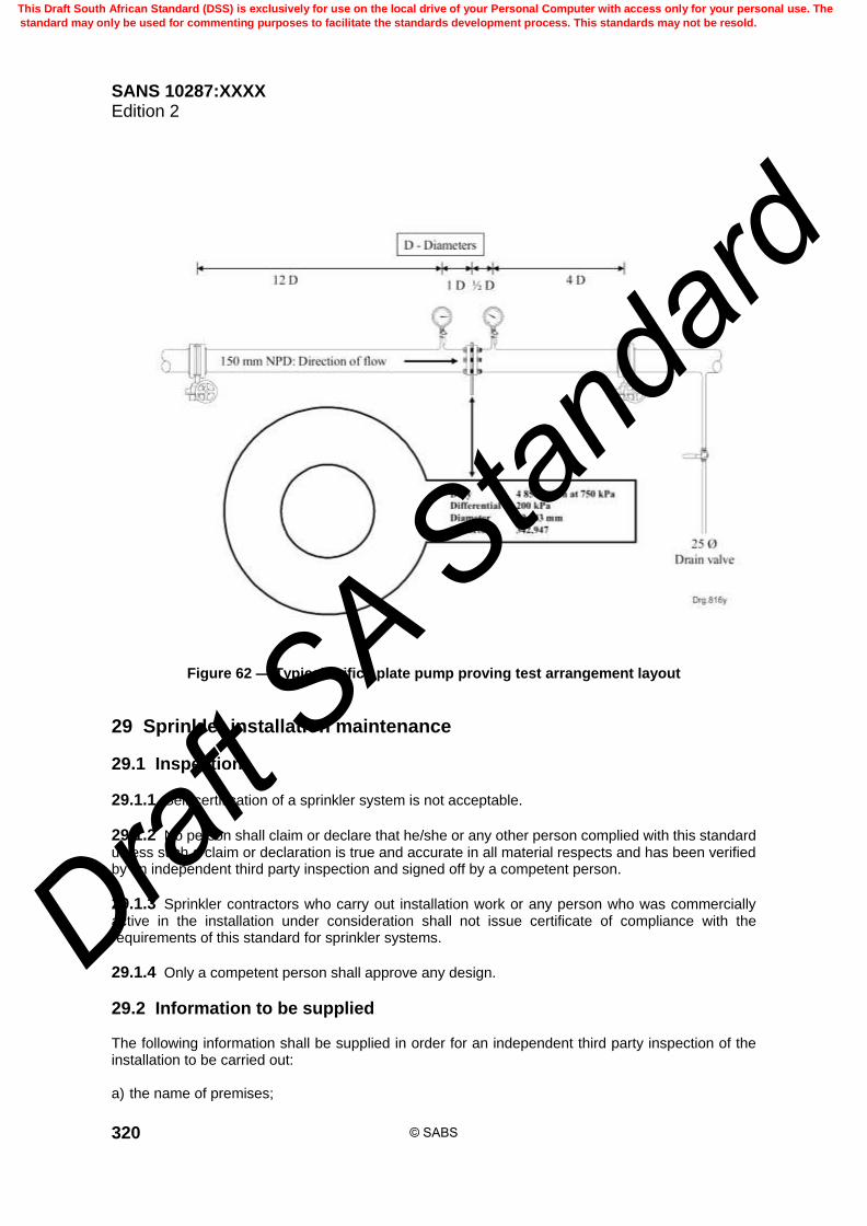
SANS 10287:XXXX Edition 2
320
Figure 62 — Typical orifice plate pump proving test arrangement layout
29 Sprinkler installation maintenance
29.1 Inspection
29.1.1 Self-certification of a sprinkler system is not acceptable.
29.1.2 No person shall claim or declare that he/she or any other person complied with this standard unless such a claim or declaration is true and accurate in all material respects and has been verified by an independent third party inspection and signed off by a competent person.
29.1.3 Sprinkler contractors who carry out installation work or any person who was commercially active in the installation under consideration shall not issue certificate of compliance with the requirements of this standard for sprinkler systems.
29.1.4 Only a competent person shall approve any design.
29.2 Information to be supplied The following information shall be supplied in order for an independent third party inspection of the installation to be carried out: a) the name of premises;
© SABS
This Draft South African Standard (DSS) is exclusively for use on the local drive of your Personal Computer with access only for your personal use. The
standard may only be used for commenting purposes to facilitate the standards development process. This standards may not be resold.
Draft S
A Stan
dard

SANS 10287:XXXX Edition 2
321
b) physical location of premises; c) the name of client occupying premises or owner of premises; d) a postal address of client occupying premises or owner of premises; and e) contact person and contact details of responsible person.
29.3 Documentation All documents submitted for approval shall be identified as follows: a) Drawing or document number or reference. b) Issue number. c) Date of issue. d) Name of project. e) Drawing or document title. f) Installation number or reference. g) Reference for assumed maximum areas of operation under consideration. h) Name of designer. i) Name of the responsible person who shall not be the designer.
29.4 Water supply information 29.4.1 Town main Where a town main forms one or both of the supplies or provides in-fill to a suction tank, the following information shall be supplied: a) Nominal diameter of the town main. b) Details of town main reticulation, i.e. whether dead end or double end feed; if a dead end, the
nearest connecting double end feed main. c) A graph showing: i) The pressure/flow characteristic of the town main which shall be determined by test at a
period of peak demand and which shall be adjusted to allow for frictional losses and static head difference between the test location and the installation alarm valve "C" pressure gauge or the relevant suction tank in-fill valve.
ii) A modified pressure flow characteristic indicating the usable pressure as defined in this
standard at any flow up to the maximum system demand. iii) The system demand pressure/flow characteristic for the hydraulically most unfavourable
assumed maximum area of operation with pressures taken as at the installation alarm valve "C" pressure gauge. The date and time of test on town main.
b) A diagram showing the town main test location relative to the installation control valve.
© SABS
This Draft South African Standard (DSS) is exclusively for use on the local drive of your Personal Computer with access only for your personal use. The
standard may only be used for commenting purposes to facilitate the standards development process. This standards may not be resold.
Draft S
A Stan
dard

SANS 10287:XXXX Edition 2
322
29.4.2 Automatic pump sets Where automatic pump sets form one or more of the supplies, the following shall be supplied (see figure 24) a) Generated head graph; b) Power absorption graph; c) NPSH graph; d) A statement of power output for each prime mover; e) Installers data sheet showing
i) the pump set installed performance pressure/flow characteristic for low water level "X", and
ii) the pump set installed performance pressure/flow characteristic for normal water line. f) The system demand pressure/flow characteristic for the hydraulically most unfavourable and
favourable assumed maximum area of operation, calculated in accordance with this standard. g) Statement of available NPSH at maximum predicted flow.
29.5 Design submission For each design assumed maximum area of operation, the following shall be supplied: a) area identification; b) classification of system; c) required density of discharge, (mm/min); d) assumed maximum area of operation, (m2); e) number of sprinklers operating; f) sprinkler nominal orifice size, (mm); g) maximum area covered per sprinkler, (m2); h) pressure loss formula used. (Hazen-Williams full or simplified or Darcy-Weisbach if foam is used).
29.6 Detailed calculations For each operating sprinkler the following shall be provided on purpose designed work sheets or a computer printout: a) node or reference number. b) sprinkler nominal K factor. c) flow through sprinkler, (litres per minute).
© SABS
This Draft South African Standard (DSS) is exclusively for use on the local drive of your Personal Computer with access only for your personal use. The
standard may only be used for commenting purposes to facilitate the standards development process. This standards may not be resold.
Draft S
A Stan
dard
SANS 10287:XXXX Edition 2
323
d) pressure at entry to sprinkler or sprinkler assembly, (kPa). For each hydraulically significant pipe: a) pipe nodes or reference; b) pipe nominal bore, (mm); c) Hazen-Williams constant, "C" or shortened K pipe "K-Factor". d) flow through pipe, (litres per minute); e) length of pipe, (metres); f) numbers, types and equivalent lengths of fittings; g) static head change in pipe, (metres); h) pressures at inlet and outlet of pipe, (kPa); i) friction loss in pipe, (kPa). j) indication of flow direction.
29.7 Drawings and diagrams
29.7.1 Fully detailed and dimensioned working drawings shall be provided. All drawings shall include: a) a node or pipe reference scheme which provides unique identification of pipes, junctions, sprinkler
heads and any pipe fittings which require hydraulic consideration; b) the position of the hydraulically most unfavourable assumed maximum area of operation; c) the position of the hydraulically most favourable assumed maximum area of operation; d) the four sprinklers upon which the average density of discharge is based; and e) the height of each identified pressure value above a datum.
29.7.2 A line diagram(s) shall be supplied and include the following information: a) node or pipe reference numbers; b) distribution pipes under consideration; c) range pipes under consideration; d) sprinkler heads under consideration; e) identification of the four hydraulically most unfavourable sprinkler heads; and f) flow through and pressure at the end of each hydraulically relevant pipe.
© SABS
This Draft South African Standard (DSS) is exclusively for use on the local drive of your Personal Computer with access only for your personal use. The
standard may only be used for commenting purposes to facilitate the standards development process. This standards may not be resold.
Draft S
A Stan
dard
SANS 10287:XXXX Edition 2
324
29.7.3 A durable notice shall be affixed to the riser pipe immediately adjacent to the alarm valve set, of any installation which has been hydraulically calculated. The notice shall include at least the following information: a) Installation number. b) Installation hazard classification(s). For each hazard class within the installations: i) the system design requirements at the installation "C" gauge for the most unfavourable and
favourable assumed areas of operation. ii) the system design requirement at the pump delivery pressure gauge for the most
unfavourable and favourable assumed areas of operation. iii) Height of highest sprinklers above the "C" gauge in the most unfavourable and favourable
assumed maximum area of operation. c) Height difference between "C" gauge and pump delivery pressure gauge.
29.7.4 The following information shall be displayed in the sprinkler pump house and supplied to the third party independent inspectorate. Installers' data sheets showing: a) Pump manufacturers’ data sheets and copy of endurance test. b) schedule listing each installation technical data as required in this standard. c) A copy of the installers’ Data sheet modified to show the "as installed" performance.
30 Maintenance contracts
30.1 General
30.1.1 Sprinkler systems shall be appropriately maintained, as specified in this clause and a contract shall be place for the maintenance of the sprinkler systems, with a sprinkler servicing contractor.
30.1.2 To maintain the validity of any clearance certification, the system shall be inspected by a competent person and serviced and maintained by a sprinkler servicing contractor.
30.1.3 The review of hazard and the re-validation of any clearance certification shall be carried out by a company experienced in this field.
30.1.4 An appointed sprinkler contractor shall not carry out inspections.
30.2 Sprinkler system user personnel
30.2.1 Appointment of fire safety officials by the sprinkler system user 30.2.1.1 The sprinkler system user shall appoint a fire safety official who shall be responsible for the sprinkler systems care and maintenance. 30.2.1.2 Fire safety officials shall receive relevant training for the sprinkler systems care and maintenance.
© SABS
This Draft South African Standard (DSS) is exclusively for use on the local drive of your Personal Computer with access only for your personal use. The
standard may only be used for commenting purposes to facilitate the standards development process. This standards may not be resold.
Draft S
A Stan
dard

SANS 10287:XXXX Edition 2
325
30.2.2 Staff responsible for weekly testing and emergency actions The following shall be adhered to: a) only appropriately trained personnel shall undertake weekly testing of sprinkler systems or
emergency actions; b) appropriate staff, including security staff, within a sprinkler protected property shall be provided
with relevant instruction by the sprinkler servicing contractor on
1) the purpose of the sprinkler system,
2) how the system operates in the event of a fire,
3) what to do if the system operates either in a fire or accidentally,
4) keeping sprinkler heads clear of obstruction,
5) the avoidance of damage to sprinkler heads and pipework,
6) upkeep of records and documentation.
30.3 Maintenance documentation
30.3.1 General The sprinkler installing company shall provide the following documents: a) a maintenance and test schedule for the sprinkler system; b) a log book or folder for the sprinkler system which shall contain at least the following at system
commissioning:
1) as-built drawings and hydraulic data or calculations; 2) proprietary equipment specifications, data sheets, and maintenance requirements, including
pump data provided by the pump set supplier; 3) maintenance, inspection and test schedules;
4) where appropriate, a weekly test card;
5) the installing contractor records and reports; and
6) clearance certificates; c) comprehensive sprinkler system maintenance test schedules for pumped water supplies.
30.3.2 Records and documents Records and documents shall be kept as follows: a) appropriate records including the sprinkler system log book or folder shall be kept on the sprinkler
protected premises and updated by the fire safety official; b) when requested by any authority, these records shall be made available by the fire safety official
for inspection; c) the records shall be kept up to date and shall include at least the following:
© SABS
This Draft South African Standard (DSS) is exclusively for use on the local drive of your Personal Computer with access only for your personal use. The
standard may only be used for commenting purposes to facilitate the standards development process. This standards may not be resold.
Draft S
A Stan
dard
SANS 10287:XXXX Edition 2
326
1) details of all modifications, changes and alterations;
2) details of all work and inspections carried out on the sprinkler system;
3) details of any hazard analysis relevant to the sprinkler protection;
4) full and up to date list of emergency contacts including: the property owner or their agent, the
relevant inspection authority, the sprinkler servicing company, the sprinkler installer, the pump supplier or pump maintenance company, the electrical contractor, the central alarm station contact numbers; the suction tank supplier, and the sprinkler monitoring equipment suppliers;
5) records detailing calls to and from the central alarm station, taking the station off watch,
restoring the station back on watch and notification of alarms or faults. The details recorded shall include at least, the nature of event, date and time of the call, the name of the caller and recipient, and the central alarm station reference;
6) details of staff training.
d) The master records shall be kept in the sprinkler log book or folder off site.
30.4 Equipment and components
30.4.1 Replacement sprinklers Replacement sprinklers shall be maintained as follows: a) a stock of spare sprinklers shall be kept on the premises as replacements for operated or damaged
sprinklers; b) sprinkler spares shall be replaced within 7 d after use. The numbers specified in table 89 are a
minimum; and c) where installations contain high-temperature sprinklers, sidewall or other variations of sprinkler
pattern or contain multiple-jet-controls, an adequate number of spares shall be maintained.
30.4.2 Components and replacement parts Components shall be maintained in accordance with the supplier's instructions, and where replacement parts may be required only proprietary parts provided by the original equipment supplier, shall be used.
30.5 Planned shutdown procedure
30.5.1 Preparation for shutdown 30.5.1.1 Servicing and repairs shall be planned to ensure that work is carried out at an appropriate time and with a minimum of down-time. 30.5.1.2 During routine inspection or testing (or both), a number of defects may be revealed which require remedial attention. 29.5.1.3 Any repairs found necessary may require to be undertaken outside of normal working hours due to the possible requirements relating to occupational health and safety or a local authority requirement that systems may not be turned off during times of occupancy, for example; in an enclosed shopping mall.
© SABS
This Draft South African Standard (DSS) is exclusively for use on the local drive of your Personal Computer with access only for your personal use. The
standard may only be used for commenting purposes to facilitate the standards development process. This standards may not be resold.
Draft S
A Stan
dard
SANS 10287:XXXX Edition 2
327
30.5.1.4 Liaison with all interested parties is essential prior to the commencement of any tests or repair work. 30.5.1.5 Any servicing or repair work during weekends or public holidays shall, where possible, only be undertaken after it has been ascertained that all necessary resources are available to complete the task and re-commission the system. 30.5.1.6 It is important to plan in advance where possible, for work to be carried out, thus ensuring that all procedures are carried out with the minimum of risk and disturbance.
30.5.2 Planning for maintenance Where maintenance of a sprinkler system or building fabric is anticipated that will result in impairment of the sprinkler protection, a written maintenance plan shall be prepared by the user and agreed with the relevant authority prior to commencement of the maintenance work. The procedures outlined in this subclause shall be included in the plan.
30.5.3 Before maintenance begins The following shall be carried out: a) notification of the relevant authority and the central alarm station; b) designation of named personnel to undertake specified tasks; c) identification of resources required for the maintenance period; d) consultation with key personnel; f) inspection and review of passive and other active fire protection measures (including fire doors,
gaseous extinguishing systems and portable fire extinguishing appliances); g) rectification of impaired passive and active fire protection measures; h) reduction of stocking levels of hazardous goods (for example flammable liquids, aerosols with
flammable contents); i) notification to the fire engineering sprinkler contractor of the company procedures and regulations
with which they are required to comply (for example work permits, hot work prohibitions); j) considerations to minimizing the area of coverage isolated at any one time; k) the provision and review of a written method statement prepared by the fire engineering sprinkler
contractor; l) procedures ensuring all the necessary tools, equipment and trained personnel are available; m) consultation with staff about the work plan, increasing awareness and precautionary measures; n) procurement and placement of additional portable fire extinguishing appliances in the affected
areas, ensuring that personnel are trained in their use; o) issue of permits to commence work, whilst maintenance work is in progress; p) suspension of operations, in particular any hazardous processes machinery and plant;
© SABS
This Draft South African Standard (DSS) is exclusively for use on the local drive of your Personal Computer with access only for your personal use. The
standard may only be used for commenting purposes to facilitate the standards development process. This standards may not be resold.
Draft S
A Stan
dard

SANS 10287:XXXX Edition 2
328
q) smoking prohibition; r) implementation of regular fire patrols, during and after re-commissioning the system; s) hydrostatic pressure testing of modified pipework or pipework extensions; t) water supply performance tests if changes have been made to the water supply or the water supply
connections; u) notification to all key staff, relevant authority and the central alarm station of the reinstatement of
the sprinkler protection; v) checks to establish that all valves, switches and other equipment have been restored to their
correct stand-by setting; w) provision of a written statement or certificate by the sprinkler servicing contractor and counter
signed by the system user signifying that the work has been completed and that the system is fully operational;
x) re-validation of the clearance certificate; and z) statements and certificates shall be filed in the sprinkler system log book.
30.5.4 Permission for installation or zone shutdown 30.5.4.1 Only the user shall give permission for a sprinkler installation or zone to be shut down for any reason other than an emergency. 30.5.4.2 Some of the authorities specified may ask to be informed whenever a sprinkler installation is shutdown.
30.5.5 Pre-shutdown checks Before a system is wholly or partly shutdown every part of the premises shall be checked to ensure that there is no indication of fire.
30.6 Notification of shutdown
30.6.1 Advising the relevant authority 30.6.1.1 Except where there are contingency plans previously agreed with the relevant authority, the fire safety official shall advise all the relevant authority in advance, of any intention to shut down all or part of an installation. 30.6.1.2 When all or part of a life safety sprinkler installation is not operational the relevant authority may wish to restrict access to the premises until the sprinkler installation is fully operational.
30.6.2 Informing other users 30.6.2.1 Where premises are subdivided into separate occupancies constituting buildings in communication or at risk protected by common sprinkler systems or installations, the fire safety official shall consult the various occupiers about the shutdown plans. 30.6.2.2 Particular attention shall be given to situations where installation pipework passes through walls or ceilings as these may feed sprinklers in areas needing special consideration, or notification of further personnel may be needed if the water is turned off.
© SABS
This Draft South African Standard (DSS) is exclusively for use on the local drive of your Personal Computer with access only for your personal use. The
standard may only be used for commenting purposes to facilitate the standards development process. This standards may not be resold.
Draft S
A Stan
dard

SANS 10287:XXXX Edition 2
329
30.7 Unplanned shutdown procedure When an installation is rendered inoperative as a matter of urgency or by accident, the precautions in as far as they are applicable shall be observed with the least possible delay.
30.8 Notification of shutdown
30.8.1 Advising the relevant authority 30.8.1.1 For life safety systems, the relevant authority, shall be advised by the fire safety official immediately of any emergency shutdown, except where there are contingency plans previously agreed with the relevant authority covering compensating actions. 30.8.1.2 The plans shall be put into effect immediately following the shutdown. 30.8.1.3 When all or part of a life safety sprinkler installation is not operational the relevant authority may wish to restrict access to the premises until the sprinkler installation is fully operational.
30.8.2 Informing other users Where premises are subdivided into separate occupancies constituting buildings in communication or a risk protected by common sprinkler system or installations, the fire safety official shall advise the various occupiers that the water is to be turned off.
30.9 Precautions and procedures when a system is not operational
30.9.1 Minimizing the effects 30.9.1.1 Maintenance, alterations and repair of systems not fully operational shall be carried out in a way that will minimize the time and extent of non-operation. 30.9.1.2 When an installation is rendered inoperative the user shall implement compensatory measures. 30.9.1.3 Alterations and repairs to an installation or its water supply (except possibly a life safety installation) shall be carried out during normal working hours. 30.9.1.4 Supervisory staff in the areas affected shall be notified so that the best possible use may be made of the hand extinguishing appliances in case of fire. 30.9.1.5 The area affected shall be patrolled continuously. 30.9.1.6 Any hot work shall be subject to a permit system. 30.9.1.7 Smoking and naked lights shall be prohibited in the vicinity. 30.9.1.8 When an installation remains inoperative outside working hours all fire doors and fire shutters shall be closed for the period concerned. 30.9.1.9 Arrangements shall be made to have fire extinguishing appliances in special readiness with sufficient trained personnel available to handle them.
30.9.2 Reinstatement of serviceable parts of an installation 30.9.2.1 As much as possible the installation shall be retained in an operative condition by blanking-off pipework feeding the inoperative part or parts where work is taking place.
© SABS
This Draft South African Standard (DSS) is exclusively for use on the local drive of your Personal Computer with access only for your personal use. The
standard may only be used for commenting purposes to facilitate the standards development process. This standards may not be resold.
Draft S
A Stan
dard

SANS 10287:XXXX Edition 2
330
30.9.2.2 Where possible, parts of installations shall be reinstated to provide some protection overnight by using blinders and blanks within the pipework. The blinders and blanks shall be fitted with visible indicator tags numbered and logged to aid timely removal.
30.9.3 Reducing the fire risk in manufacturing premises In the case of manufacturing premises, where the alterations or repairs are extensive, or it is necessary to disconnect a pipe exceeding 40 mm nominal diameter, or to overhaul or remove a main stop valve, alarm valve or non-return valve, every effort shall be made to carry out the work whilst the machinery is stopped.
30.9.4 Pump isolation Any pump out of commission shall be isolated by means of the valves provided.
30.10 Additional precautions for zoned systems
30.10.1 Systems other than life safety sprinkler installations Only the smallest part of the installation or zone in a multi-zone installation shall be isolated or shutdown at a time for maintenance. An installation or complete shutdown of a zone shall be avoided where necessary.
30.10.2 Life safety sprinkler systems Only one zone of a multi-zone installation shall be shut down at a time. An installation or zone shall be shut down for the minimum time necessary for maintenance.
30.11 Installation control valves on life safety systems
30.11.1 Duplicate installation control valve sets and alarm valves with a bypass arrangement may have the alarm valves separately serviced at any time, provided the water supply to the installation is maintained.
30.11.2 The following procedure shall be used before servicing duplicate alarm valves: a) check, and if necessary open, the stop valves to the standby alarm valve; b) close one of the stop valves to the alarm valve to be serviced and immediately carry out an alarm
test on the other alarm valve; and c) if water is not available open the stop valve immediately, and rectify the fault before proceeding.
30.12 Water availability When a zone (or zones) is charged, or recharged with water after draining, the flushing valve(s) shall be used to check that water is available in the zone (or zones).
30.13 Action following sprinkler operation
30.13.1 General 30.13.1.1 Following shutdown after operation of an installation, the operated sprinkler heads shall be replaced by heads of the correct type and temperature rating by a sprinkler installer, and the water supply restored.
© SABS
This Draft South African Standard (DSS) is exclusively for use on the local drive of your Personal Computer with access only for your personal use. The
standard may only be used for commenting purposes to facilitate the standards development process. This standards may not be resold.
Draft S
A Stan
dard

SANS 10287:XXXX Edition 2
331
30.13.1.2 Unopened sprinklers around the area in which operation took place shall be checked for damage by heat or other cause and replaced as necessary. 30.13.1.3 Where incidents occur within a sprinkler protected property resulting in a release of water from a sprinkler installation, consideration should be given to the completion and return of an incident report form. 30.13.1.4 Development of sprinkler protection technology, in part, depends on having an insight into the performance of sprinklers in buildings. 30.13.1.5 The water to an installation or zone of an installation that has operated shall not be shut off until any fire has been extinguished.
30.13.1.6 The decision to shut down an installation or zone which has operated because of a fire may only be taken by the relevant authority. 30.13.1.7 Components removed from the system shall be retained by the user for possible examination by a relevant authority.
30.13.2 Dry-pipe installations protecting cold storage warehouses (air circulation refrigeration) The installation shall be dismantled for drying out after each operation.
30.14 Maintenance and repairs 30.14.1 The user shall ensure that a programme of inspections and checks is carried-out, and arrange for testing, servicing and maintenance in accordance with a documented schedule. 30.14.2 Regular inspections and tests shall be carried out under the instructions of the fire safety official. 30.14.3 Inspections and tests shall be conducted at specified intervals. The tests shall be recorded on the weekly test card or on a dedicated test record sheet. 30.14.4 The central alarm station shall be notified of any system tests which will result in the transmission of an alarm. The central alarm station shall be requested to verify that an alarm signal has been received. The central alarm station shall be informed immediately that the test procedures have been completed. 30.14.5 The inspection authority shall provide test cards for record keeping purposes by the sprinkler system user.
31 Programme of inspection and checking
31.1 General The installer shall provide the user with an inspection and checking programme for the system. The programme shall include instruction on the action to be taken in respect of faults, operation of the system in particular the procedure for emergency manual starting of any pumps.
31.2 Daily routine
31.2.1 General The daily routine shall be carried out on each day that the premises are in normal use.
© SABS
This Draft South African Standard (DSS) is exclusively for use on the local drive of your Personal Computer with access only for your personal use. The
standard may only be used for commenting purposes to facilitate the standards development process. This standards may not be resold.
Draft S
A Stan
dard

SANS 10287:XXXX Edition 2
332
31.2.2 Relevant authority and remote central station alarm connection 31.2.2.1 If the circuits are not continuously monitored, the equipment for automatic transmission of alarm signals from a sprinkler installation to a relevant authority or remote manned centre shall be checked for a) continuity of the connection, and b) continuity of the connection between the alarm switch and the control unit. 31.2.2.2 The testing procedure shall be agreed upon with the relevant authority or remote central station centre to avoid false calls. The relevant authority or remote central station may carry out the test and may be prepared to give an undertaking to do so. 31.2.2.3 A relevant local authority may obtain assistance from other sources, (for example, it may purchase services from the private sector), if it does not have within its organization persons who are competent to carry out the tasks envisaged in this standard.
31.3 Weekly routine
31.3.1 General Each part of the weekly routine shall be carried out at intervals of not more than 7 d.
31.3.2 Checks The following shall be checked and recorded: a) any signs of leakage from the system; b) all water and air pressure gauge readings on installations, trunk mains and pressure tanks; c) all water levels in elevated private reservoirs, rivers, canals, lakes, water storage tanks (including
pump priming water tanks) and pressure tanks; and d) the correct position of all main stop valves.
31.3.3 Pump suction tanks 31.3.3.1 The access ladder to all sprinkler water storage tanks shall be checked for correct housing and security and any tank in-fill flow control or ball valve covers shall be secured and locked. 31.3.3.2 Checks on the suction tanks shall include: a) ensuring that all valves are in their correct operative positions specifically: i) The incoming town main feed valves to the suction tank, and ii) The main suction line isolating valves feeding the pumps. b) ensuring that the tank is full and the level indicators are working correctly.
31.3.4 General check of pump house equipment Check all main control and isolating valves are in their correct operative positions. Check the electrical supply on the voltmeters.
© SABS
This Draft South African Standard (DSS) is exclusively for use on the local drive of your Personal Computer with access only for your personal use. The
standard may only be used for commenting purposes to facilitate the standards development process. This standards may not be resold.
Draft S
A Stan
dard

SANS 10287:XXXX Edition 2
333
Check the isolators on the pump house distribution board.
31.3.5 Automatic pump starting test 31.3.5.1 Tests on automatic pumps shall include instructions to: a) reduce water pressure on the starting device, thus simulating the condition of automatic starting. b) When the pump starts record the starting (cut in) pressure, and check that this is correct. c) on diesel pumps, check the oil pressure where gauges are fitted, and the flow of cooling water
through open circuit cooling systems. 31.3.5.2 The typical auto-start tier arrangement can be seen in figure 63. Testing of each tier arrangement shall proceed as follows: a) Close test valve A; b) Slowly open test valve B until a pressure drop is noted; c) Monitor the pressure drop and note the pressure at which the pump being tested comes into
operation; d) Close test valve B, and e) Open Test valve A. 31.3.5.3 Test each tier level on the auto-start arrangement making note of: a) The jockey pump cut in and cut out pressures, and b) The main fire pumps cut in pressures manually shutting down each unit before testing the next.
© SABS
This Draft South African Standard (DSS) is exclusively for use on the local drive of your Personal Computer with access only for your personal use. The
standard may only be used for commenting purposes to facilitate the standards development process. This standards may not be resold.
Draft S
A Stan
dard
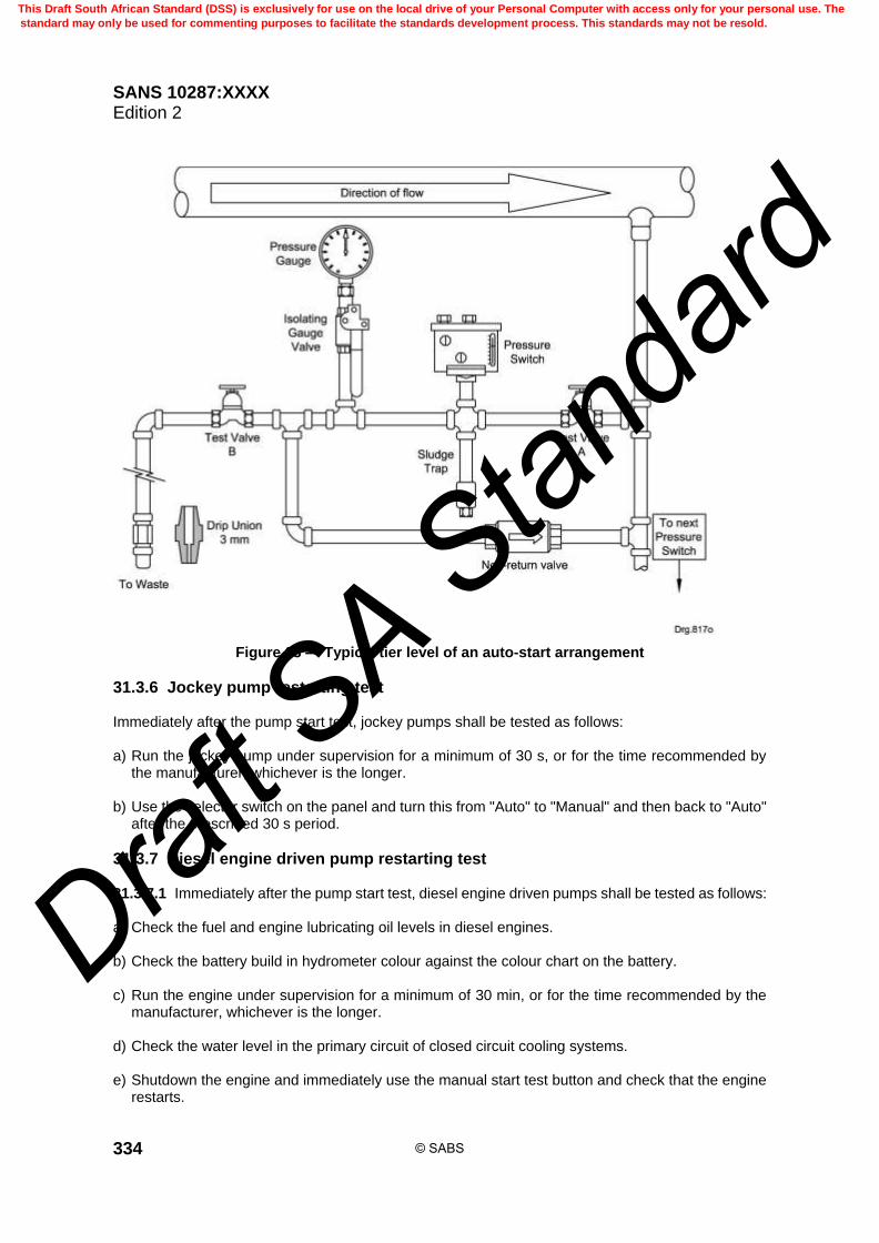
SANS 10287:XXXX Edition 2
334
Figure 63 — Typical tier level of an auto-start arrangement
31.3.6 Jockey pump restarting test Immediately after the pump start test, jockey pumps shall be tested as follows: a) Run the jockey pump under supervision for a minimum of 30 s, or for the time recommended by
the manufacturer, whichever is the longer. b) Use the selector switch on the panel and turn this from "Auto" to "Manual" and then back to "Auto"
after the prescribed 30 s period.
31.3.7 Diesel engine driven pump restarting test 31.3.7.1 Immediately after the pump start test, diesel engine driven pumps shall be tested as follows: a) Check the fuel and engine lubricating oil levels in diesel engines. b) Check the battery build in hydrometer colour against the colour chart on the battery. c) Run the engine under supervision for a minimum of 30 min, or for the time recommended by the
manufacturer, whichever is the longer. d) Check the water level in the primary circuit of closed circuit cooling systems. e) Shutdown the engine and immediately use the manual start test button and check that the engine
restarts.
© SABS
This Draft South African Standard (DSS) is exclusively for use on the local drive of your Personal Computer with access only for your personal use. The
standard may only be used for commenting purposes to facilitate the standards development process. This standards may not be resold.
Draft S
A Stan
dard

SANS 10287:XXXX Edition 2
335
f) Ensure the diesel engine driven pump runs continuously for not less than 30 min. 31.3.7.2 Oil pressure (where gauges are fitted), engine temperatures and coolant flow shall be monitored throughout the test. 31.3.7.3 Oil hoses shall be checked and a general check made for leakage of fuel, coolant or exhaust fumes.
31.3.8 Electric motor driven pump restarting test Immediately after the pump start test, electric motor driven pumps shall be tested as follows: a) Run the motor under supervision for a minimum of ten minutes, or for the time recommended by
the manufacturer, whichever is the longer. b) Check the sight glass in order to ensure water is discharging from the cooling water line fitted to
the pump. c) Shutdown the motor and immediately use the manual start test button and check that the engine
restarts. d) Ensure the electric motor driven pump runs continuously for not less than 5 min.
31.3.9 Water motor alarm test
31.3.9.1 Each water motor alarm shall be sounded continuously for not less than 30 s, by opening a test valve and flowing water to waste through an open nozzle, 15 mm or 25 mm test pipe as appropriate.
31.3.9.2 Where fire pumps are installed, the water motor alarm test shall be carried out only after testing the units is complete. It shall be ensured that when testing the main fire pump comes into operation and that the water flow to the alarm bell is not maintained by the jockey pump. 31.3.9.3 This verifies that the alarm will not ring intermittently. 31.3.9.4 The test may also automatically test any relevant authority or remote central station connection. 31.3.9.5 Automatic pump starting test Tests on automatic pumps shall include instructions to a) check the fuel and engine lubricating oil levels in diesel engines, b) reduce water pressure on the starting device, thus simulating the condition of automatic starting, c) when the pump starts record the starting (cut-in) pressure, and check that this is correct, and d) on diesel pumps, check the oil pressure where gauges are fitted, and the flow of cooling water
through open circuit cooling systems. 31.3.9.6 Monitored systems including zoned and life safety systems 31.3.9.6.1 The mode (fully open or fully closed as the case may be) monitoring system for stop valves (including zone valves) on monitored systems, including zoned and life safety installations, shall be tested for satisfactory operation.
© SABS
This Draft South African Standard (DSS) is exclusively for use on the local drive of your Personal Computer with access only for your personal use. The
standard may only be used for commenting purposes to facilitate the standards development process. This standards may not be resold.
Draft S
A Stan
dard

SANS 10287:XXXX Edition 2
336
31.3.9.6.2 The weekly alarm test shall be carried out without alteration of the setting of stop valves to duplicate installation control valve sets. 31.3.9.7 Relevant authority and remote central station alarm connection 31.3.9.7.1 The equipment for automatic transmission of alarm signals from a sprinkler installation to a relevant authority or remote manned centre shall be checked for a) continuity of the connection, and b) continuity of the connection between the alarm switch and the control unit, if the circuits are
continuously monitored. 31.3.9.7.2 The testing procedure shall be agreed upon with the relevant authority to avoid false calls. The relevant authority may carry out the test and may be prepared to give an undertaking to do so. 31.3.10 Trace heating and localized heating systems Heating systems to prevent freezing in the sprinkler system shall be checked for correct function. 31.3.11 Water storage tanks security The access ladder to all sprinkler water storage tanks shall be checked for correct housing and security and any tank in-fill flow control or ball valve covers shall be secured and locked.
32 Service maintenance and review schedule
32.1 General procedures In addition to the identified procedures, any procedures specified by component suppliers or the relevant inspection authority shall also be carried out.
32.2 Records Sprinkler servicing contractors shall carry out the schedule requirements. The sprinkler inspecting authority shall provide advice on any rectification that needs to be carried out or is needed and advise on any external factors, for example, weather conditions, which may have affected the results.
32.3 Quarterly routine 31.3.1 The quarterly routine shall be carried out, and shall include the daily and weekly maintenance procedures. 32.3.2 Before sprinkler servicing contractors test any installation in any way that might release water, they may wish to obtain an indemnity, signed by the person owning the work site or premises at that time. This shall also indemnify them from a claim from the tenants of the owner.
32.4 Review of hazard
32.4.1 The effect of any changes of structure, occupancy, fire hazard, heating, lighting or equipment of a building on hazard classification or installation design shall be considered.
32.4.2 The sprinkler protection user shall be notified of any non-compliance and corrective action initiated immediately.
32.4.3 The sprinkler protection user shall notify any relevant party of the non-compliance.
32.4.4 Non-compliance may invalidate any certification that is in force.
© SABS
This Draft South African Standard (DSS) is exclusively for use on the local drive of your Personal Computer with access only for your personal use. The
standard may only be used for commenting purposes to facilitate the standards development process. This standards may not be resold.
Draft S
A Stan
dard

SANS 10287:XXXX Edition 2
337
32.4.5 Any assessment of a change in occupancy or fire hazard is to include changes to materials and products used or manufactured method of storage and storage heights.
32.5 Sprinklers, multiple-jet-controls and sprayers
32.5.1 Sprinklers, multiple-jet-controls and sprayers shall be free from deposits, which may influence their performance.
32.5.2 Dusty components shall be carefully cleaned.
32.5.3 Distorted or contaminated (for example paint) sprinkler heads, concealed sprinkler head cover plates, multiple-jet-controls or sprayers shall be replaced.
32.5.4 Where corrosive conditions occur, petroleum jelly coatings shall be checked.
32.5.5 Where necessary the existing coatings shall be removed and the sprinklers, multiple-jet-controls or sprayers shall be coated twice with good-quality petroleum jelly, (in the case of glass bulb sprinklers to the sprinkler body and yoke only).
32.5.6 Particular attention shall be paid to sprinklers in spray booths, where more frequent cleaning, replacement of paper or cellophane bags or protective measures may be necessary.
32.6 Pipework and hangers — Above ground
32.6.1 Pipework and hangers shall be checked tor corrosion and painted as necessary.
32.6.2 Bitumen-based paint on pipework, including the threaded ends of galvanized pipework, and hangers in corrosive occupancies shall be renewed as necessary.
32.6.3 Bitumen-based paint may need renewal at intervals varying from one to five years according to the severity of the conditions.
32.6.4 Tape wrapping on pipes shall be repaired as necessary.
32.7 Checks for electrical connections
32.7.1 The pipework shall be checked for electrical earthing connections.
32.7.2 The sprinkler-protection user shall be notified of any electrical equipment earthing connections on sprinkler pipework.
32.7.3 Alternative electrical earthing arrangements shall be made.
32.8 Water supplies and their alarms
32.8.1 Each water supply shall be tested with each installation in the system.
32.8.2 The pump(s), if fitted, in the supply shall start automatically and the supply pressure at the appropriate flow rate shall be not less than the appropriate value given. Corrective action shall be taken if necessary.
32.8.3 Corrective action shall also be taken if the pressure is lower than the value recorded at commissioning or in terms of this standard.
© SABS
This Draft South African Standard (DSS) is exclusively for use on the local drive of your Personal Computer with access only for your personal use. The
standard may only be used for commenting purposes to facilitate the standards development process. This standards may not be resold.
Draft S
A Stan
dard

SANS 10287:XXXX Edition 2
338
32.9 Electrical supplies
32.9.1 Open nickel-cadmium batteries 32.9.1.1 Where open nickel-cadmium batteries are installed, the electrolyte level and density of all open nickel-cadmium cells (including those in diesel engine starter batteries and those for control panel power supplies) shall be checked. 32.9.1.2 If the density is low the battery charger shall be checked and if necessary repaired or replaced. If the charger is working correctly, the battery or batteries affected shall be replaced.
32.9.2 Secondary electrical supplies from diesel generators 32.9.2.1 The system shall be checked for satisfactory operation. 32.9.2.2 The sprinkler protection user shall be notified of any faults. 32.9.2.3 If faults are found, the sprinkler protection user is responsible for, and he/she shall take corrective action.
32.10 Stop valves
32.10.1 All stop valves controlling the flow of water to sprinklers shall be manipulated to ensure that they are in working order, and securely re-fastened in the correct mode.
32.10.2 This includes the stop valves on all water supplies, at the alarm valve(s) and all zone or other subsidiary stop valves.
32.11 Flow switches Flow switches shall be operated and if necessary corrected.
32.12 Replacement parts Replacement parts held as spares shall be checked for number and condition and supplemented as required.
32.13 Half-yearly routine The half-yearly routine shall be carried out, and shall include the quarterly, weekly and daily maintenance procedures. The half-yearly checks and inspections shall be made at intervals of not more than six months by an independent competent person experienced in this field. Before sprinkler servicing contractors test any installation in any way that might release water, they may wish to obtain an indemnity, signed by the person owning the work site or premises at that time. This shall also indemnify them from a claim from the tenants of the owner.
32.14 Dry alarm valves
32.14.1 Dry alarm valves, accelerators and exhausters, in dry pipe installations and tail-end extensions shall be exercised.
32.14.2 In order to exercise the dry alarm valve, either remove the inspection cover plate, if fitted, and manually operate the moving parts or comply with the supplier’s instructions. Alternatively, if a
© SABS
This Draft South African Standard (DSS) is exclusively for use on the local drive of your Personal Computer with access only for your personal use. The
standard may only be used for commenting purposes to facilitate the standards development process. This standards may not be resold.
Draft S
A Stan
dard

SANS 10287:XXXX Edition 2
339
subsidiary stop valve is fitted downstream of the alarm valve, close the subsidiary stop valve, prime the space between the dry pipe valve clack and the underside of the subsidiary valve with water, and open the installation drain valve.
32.14.3 Alternate systems need not be tested in this way since they are exercised twice a year as a result of the change-over from wet to dry operation, and back.
32.15 Relevant authority and remote central station alarms
32.15.1 The electrical installation shall be checked for satisfactory operation. The sprinkler protection user shall be notified of any faults.
32.15.2 If faults are found, the sprinkler protection user is responsible for, he or she shall take corrective action.
32.16 Yearly routine
32.16.1 The yearly routine shall be carried out, and shall include the half-yearly, quarterly, weekly and daily maintenance procedures.
32.16.2 The checks and inspections shall be made at intervals of not more than 12 months.
32.17 Deluge, recycling and alternate wet and dry valves All deluge, recycling and alternate wet and dry valves, alarm and non-return valves shall be examined, tested and overhauled or replaced if necessary.
32.18 Diesel engine and electric motor driver and pump service
32.18.1 The diesel engine and pump shall be serviced on an annual basis by competent person who is experienced in the requirements relating to sprinkler installation pumped water supplies.
32.18.2 The electric motor and pump shall be serviced on an annual basis by a suitably qualified person who is experienced in the requirements relating to sprinkler installation pumped water supplies.
32.18.3 An identifying name and date tag stating when last overhauled shall be affixed to the engine.
32.19 Automatic pump flow test
32.19.1 Each water supply pump in the installation shall be tested at the full load condition by means of the test line connection coupled to the pump delivery branch downstream of the pump outlet non-return valve and shall deliver the system design requirements.
32.19.2 Allow for pressure losses in the supply pipe and valves between the source and the "C" gauge of each installation and calculate these in accordance with the requirements.
32.20 Diesel engine fail-to-start test — Abortive start routine The fail-to-start (pump failure) alarm shall operate after the sixth cycle of cranking, when the following procedure is carried out: a) the fuel supply is isolated;
© SABS
This Draft South African Standard (DSS) is exclusively for use on the local drive of your Personal Computer with access only for your personal use. The
standard may only be used for commenting purposes to facilitate the standards development process. This standards may not be resold.
Draft S
A Stan
dard

SANS 10287:XXXX Edition 2
340
b) the engine is cranked for not less than 15 s; c) cranking is stopped for not less than 10 s and not more than 15 s; and d) the above are repeated a further five times on alternating batteries.
32.21 Manual start test The engine shall start immediately when, after the abortive test is carried out and the fuel supply restored, the manual starting system is operated.
32.22 Float valves or automatic flow control valves on water storage Float valves or automatic flow control valves on water storage tanks shall be checked for correct function.
32.23 Three-yearly routine
32.23.1 The three-yearly routine shall be carried out, and shall include the yearly, half-yearly, quarterly, weekly and daily maintenance procedures.
32.23.2 All checks and inspections previously noted shall be made at intervals of not more than three years.
32.23.3 All batteries within a pump house shall be replaced.
33 Suction and gravity tanks
33.1 All tanks shall be examined externally for corrosion.
33.2 Suction tanks shall
a) be examined externally and internally for corrosion; and b) be drained if required for cleaning or repainting (or both) and have the corrosion protection
refurbished (or both) as necessary with a specification which is approved in order to prevent the fabric of the tank being attended to for at least a three year period.
c) have an identifying name and date tag affixed to the valves stating when last inspected/refurbished.
33.3 All tanks shall be repainted or have the corrosion protection refurbished (or both), as necessary.
33.4 Welded steel tanks shall be drained, cleaned as necessary, examined internally and externally
for corrosion and repainted in accordance with the specification detailed in this standard which shall be adhered to.
33.5 An identifying name and date tag stating when last overhauled shall be affixed to the tanks.
34 Water supply stop valves, alarm and non-return valves All water supply stop valves, alarm and non-return valves shall be examined, tested and overhauled or replaced if necessary. An identifying name and date tag stating when last overhauled shall be affixed to the valves.
© SABS
This Draft South African Standard (DSS) is exclusively for use on the local drive of your Personal Computer with access only for your personal use. The
standard may only be used for commenting purposes to facilitate the standards development process. This standards may not be resold.
Draft S
A Stan
dard

SANS 10287:XXXX Edition 2
341
35 Gauges Pressure gauges shall be tested with a calibrated gauge and shall be replaced or recalibrated if required.
36 Ten yearly routine Dry barrel sprinklers shall either be replaced at ten year intervals or a representative sample shall be tested every 10 years and then at 10 year intervals thereafter.
37 Fifteen-yearly routine At not more than 15-year intervals, galvanized sectional steel tanks used as pump suction tanks shall be a) drained, b) cleaned or polished as necessary, and c) examined internally and the fabric attended to as necessary.
38 Twenty-five-yearly routine
38.1 Sprinkler heads
38.1.1 At not more than 25 year intervals a random selection of ten sprinklers shall be removed from each sprinkler installation and tested for correct operation, operation temperature, variation of K-Factor, spray obstacles and possible lodgement problems.
38.1.2 A smaller population sample, subject to a minimum of two sprinklers per valve set and not less than ten in total, whichever is the greater, can be taken if there are multiple valves feeding systems with the same year of installation within the same environment.
38.1.3 Should a single control valve feed multiple areas of different occupancy classifications then a minimum of two sprinklers per each different occupancy classification, but not less than ten in total number of samples, whichever is the greater, shall be submitted.
38.1.4 Failure of the sprinklers to operate within the allowable temperature band or any other test that suggests the sprinklers are suspect and may not operate as designed under a fire condition means that replacement of all sprinklers of that installation or within the area they were removed from shall take place. Should the sprinklers pass the required testing they shall be retested at ten year intervals.
38.2 Corrosive atmospheres Where sprinklers are installed in harsh environmental or corrosive atmospheres or water supplies they shall either be replaced at five year intervals or a representative sample shall be tested every five years and then at five year intervals thereafter.
© SABS
This Draft South African Standard (DSS) is exclusively for use on the local drive of your Personal Computer with access only for your personal use. The
standard may only be used for commenting purposes to facilitate the standards development process. This standards may not be resold.
Draft S
A Stan
dard
SANS 10287:XXXX Edition 2
342
38.3 Pipework
38.3.1 The pipework shall be thoroughly flushed out and hydrostatically tested to a pressure equal to the maximum static pressure or 1,800 kPa, whichever is higher.
38.3.2 All installations of 25 years of age or older or where there are obvious signs of corrosion shall have sections of pipe removed for inspection and any defect that might adversely affect the performance of the system shall be eliminated.
38.3.3 Should pipes from a control valve be present within cold rooms, fridges, delivery bays, especially near coastal regions, which may experience acceleration in the rate of development of corrosion, at least one pipe sample shall be submitted from these area(s) to be inspected and tested.
38.3.4 For buildings that contain multiple control valves of the same year of installation and same environment, at least one-third of the total number of control valves shall be evaluated and can be used as representation for the remaining untested control valves.
38.3.5 The pipes shall be clearly marked to identify from which control valve the pipes were removed from.
38.3.6 A representative population of pipework of the following diameters shall be removed from each installation in the area closest to and farthest from the control valve assembly and from the area which is centrally located: a) the removal of a section of small diameter pipe between 25 mm to 50 mm; b) The removal of a medium diameter pipe between 65 mm and 80 mm; c) The removal of a large diameter pipe between 100 mm to 200 mm;
38.3.7 Each pipe sample shall be at least 1,0 m in length or a full section of pipe between fittings with at least one untouched fitting attached to either end.
38.3.8 If external or internal corrosion is noted, the pipes shall be examined by a corrosion expert or metallurgical engineer for opinion and any recommendations are to be adhered to. Should the sprinklers pass the required testing they shall be retested at ten year intervals.
38.4 Corrosion
38.4.1 Anaerobic bacteria are not uncommon and are relatively easily identified.
38.4.2 Every opportunity shall be taken when examining suction tanks or sprinkler pipework to determine if this is present.
38.4.3 Under correct testing procedures being carried out, anaerobic bacteria would not normally be present.
© SABS
This Draft South African Standard (DSS) is exclusively for use on the local drive of your Personal Computer with access only for your personal use. The
standard may only be used for commenting purposes to facilitate the standards development process. This standards may not be resold.
Draft S
A Stan
dard

SANS 10287:XXXX Edition 2
343
Bibliography NFPA 30, Flammable and combustible liquids code. NFPA 30B, Code for the manufacture and storage of aerosol products.
_____________
© SABS
This Draft South African Standard (DSS) is exclusively for use on the local drive of your Personal Computer with access only for your personal use. The
standard may only be used for commenting purposes to facilitate the standards development process. This standards may not be resold.
Draft S
A Stan
dard