Embed Size (px)
Citation preview
IEC/TR 61850-7-510 Edition 1.0 2012-03
TECHNICAL REPORT
Communication networks and systems for power utility automation – Part 7-510: Basic communication structure – Hydroelectric power plants – Modelling concepts and guidelines
IEC
/TR
618
50-7
-510
:201
2(E
)
®
colourinside
This document is a preview
generated by EVS

THIS PUBLICATION IS COPYRIGHT PROTECTED Copyright © 2012 IEC, Geneva, Switzerland All rights reserved. Unless otherwise specified, no part of this publication may be reproduced or utilized in any form or by any means, electronic or mechanical, including photocopying and microfilm, without permission in writing from either IEC or IEC's member National Committee in the country of the requester. If you have any questions about IEC copyright or have an enquiry about obtaining additional rights to this publication, please contact the address below or your local IEC member National Committee for further information.
IEC Central Office Tel.: +41 22 919 02 11 3, rue de Varembé Fax: +41 22 919 03 00 CH-1211 Geneva 20 [email protected] Switzerland www.iec.ch
About the IEC The International Electrotechnical Commission (IEC) is the leading global organization that prepares and publishes International Standards for all electrical, electronic and related technologies.
About IEC publications The technical content of IEC publications is kept under constant review by the IEC. Please make sure that you have the latest edition, a corrigenda or an amendment might have been published. Useful links: IEC publications search - www.iec.ch/searchpub The advanced search enables you to find IEC publications by a variety of criteria (reference number, text, technical committee,…). It also gives information on projects, replaced and withdrawn publications. IEC Just Published - webstore.iec.ch/justpublished Stay up to date on all new IEC publications. Just Published details all new publications released. Available on-line and also once a month by email.
Electropedia - www.electropedia.org The world's leading online dictionary of electronic and electrical terms containing more than 30 000 terms and definitions in English and French, with equivalent terms in additional languages. Also known as the International Electrotechnical Vocabulary (IEV) on-line. Customer Service Centre - webstore.iec.ch/csc If you wish to give us your feedback on this publication or need further assistance, please contact the Customer Service Centre: [email protected].
This document is a preview
generated by EVS
IEC/TR 61850-7-510 Edition 1.0 2012-03
TECHNICAL REPORT
Communication networks and systems for power utility automation – Part 7-510: Basic communication structure – Hydroelectric power plants – Modelling concepts and guidelines
INTERNATIONAL ELECTROTECHNICAL COMMISSION XC ICS 33.200
PRICE CODE
ISBN 978-2-88912-007-9
® Registered trademark of the International Electrotechnical Commission
®
Warning! Make sure that you obtained this publication from an authorized distributor.
colourinside
This document is a preview
generated by EVS
– 2 – TR 61850-7-510 © IEC:2012(E)
CONTENTS
FOREWORD ........................................................................................................................... 6 INTRODUCTION ..................................................................................................................... 8 1 Scope ............................................................................................................................... 9 2 Normative references ....................................................................................................... 9 3 Overall communication structure in a hydropower plant .................................................. 10
3.1 Abstract communication structure .......................................................................... 10 3.2 Communication network ........................................................................................ 10 3.3 Operational modes ................................................................................................ 12 3.4 Fundamental control strategies ............................................................................. 13 3.5 Hydro power plant specific information .................................................................. 14
4 Structuring control systems ............................................................................................ 16 4.1 Basic use of logical nodes ..................................................................................... 16 4.2 Logical device modelling ....................................................................................... 16 4.3 Example of application for an excitation system .................................................... 19
4.3.1 General ..................................................................................................... 19 4.3.2 Voltage regulation example ....................................................................... 22 4.3.3 PSS example ............................................................................................. 24
4.4 Example of application for a turbine governor system ............................................ 25 4.4.1 Conditions of this example ......................................................................... 25 4.4.2 Signal hierarchy ........................................................................................ 25 4.4.3 Basic overview .......................................................................................... 26 4.4.4 Detailed description of used structure ........................................................ 28
4.5 Examples of how to reference a start / stop sequencer of a unit ............................ 34 4.5.1 General ..................................................................................................... 34 4.5.2 Unit sequences definition with IEC 61850 .................................................. 34 4.5.3 Start sequence from a state “stopped” to a state "speed no load not
excited” (included in LD named “SEQ_SnlNexStr”) .................................... 35 4.5.4 Start sequence from state “speed no load not excited” to state
“generation” (included in LD named “SEQ_SnlExcStr” and “SEQ_GenStr”) .......................................................................................... 37
4.5.5 Stop sequence from state “generator” to state “speed no load not excited” (included in LD named “SEQ_GridFaultStop”) .............................. 38
4.5.6 Shutdown sequence from state “generator” to state “stopped” (SEQ_NormalStop) .................................................................................... 40
4.5.7 Quick shutdown sequence from state “generator” to state “stopped” (SEQ_QuickStop) ...................................................................................... 42
4.5.8 Emergency shutdown sequence from state “generator” to state “stopped” (SEQ_EmgStop) ........................................................................ 45
5 Variable speed system example ..................................................................................... 47 5.1 Example of block diagrams and logical nodes of variable speed pumped
storage system ...................................................................................................... 47 5.2 Example of application for an excitation system of variable speed pumped
storage .................................................................................................................. 49 5.2.1 General ..................................................................................................... 49 5.2.2 Automatic power regulator example ........................................................... 49
This document is a preview
generated by EVS
TR 61850-7-510 © IEC:2012(E) – 3 –
5.2.3 Power detector example ............................................................................ 50 5.2.4 Gate pulse generator example ................................................................... 50
5.3 Example of governor system ................................................................................. 51 5.3.1 Guide vane opening function example ....................................................... 51 5.3.2 Guide vane controller example .................................................................. 52 5.3.3 Speed controller example .......................................................................... 53 5.3.4 Optimum speed function example .............................................................. 53
5.4 Example of how to reference a start / stop sequencer for variable speed pumped storage system ........................................................................................ 54 5.4.1 Unit sequences definition for conventional and variable speed
pumped storage ......................................................................................... 54 5.4.2 Start sequence from a state "Stopped" to a state "Synchronous
Condenser (SC) mode in pump direction" .................................................. 55 5.4.3 Start sequence from a state "Synchronous Condenser (SC) mode in
Pump direction" to a state "Pumping"......................................................... 56 5.4.4 Mode Transition sequence from a state "Pumping" to a state
"Synchronous Condenser (SC) mode in Pump direction" ........................... 57 5.4.5 Sequence from a state "pumping" to a state "stopped" .............................. 58 5.4.6 Emergency shutdown sequence from a state "pumping" to a state
"stopped" ................................................................................................... 60 5.4.7 Shutdown sequence from a state "Synchronous Condenser (SC)
mode in pump direction" to a state "stopped" ............................................. 61 5.4.8 Emergency shutdown sequence from a state "Synchronous
Condenser (SC) mode in pump direction" to a state "stopped" ................... 62 6 Pump start priorities of a high pressure oil system .......................................................... 64
6.1 Example of a pump start priority for high pressure oil system ................................ 64 6.1.1 General ..................................................................................................... 64 6.1.2 Sequence to manage a pump start priorities .............................................. 64 6.1.3 Sequence to manage a pump .................................................................... 67
7 Addressing structures, examples of mapping .................................................................. 68 7.1 Basic principles (IEC 61850-6) .............................................................................. 68 7.2 Decentralised ICD file management....................................................................... 68 7.3 Centralised ICD file management .......................................................................... 69 7.4 Power plant structure – ISO/TS 16952-10 (Reference Designation System –
Power Plants) ........................................................................................................ 70 7.4.1 ISO/TS 16952-10 (Reference Designation System – Power Plants) ........... 70 7.4.2 Example 1: Wicket gate indications ........................................................... 73 7.4.3 Example 2: 3 Phase Measurement............................................................. 74 7.4.4 Example 3: Speed Controller ..................................................................... 74 7.4.5 Example 4: Speed measurement with some thresholds .............................. 75 7.4.6 Example 5: Common turbine information ................................................... 76
8 Examples of how to use various types of curves and curve shape descriptions ............... 76 9 Examples of voltage matching function ........................................................................... 80 Bibliography .......................................................................................................................... 82 Figure 1 – Structure of a hydropower plant ........................................................................... 10 Figure 2 – Simplified network of a hydropower plant ............................................................. 12 Figure 3 – Principles for the joint control function .................................................................. 14 Figure 4 – Water flow control of a turbine.............................................................................. 15
This document is a preview
generated by EVS
– 4 – TR 61850-7-510 © IEC:2012(E)
Figure 5 – Pressurised oil systems with LD suffix and with LN prefix ..................................... 18 Figure 6 – Examples of logical nodes used in an excitation system ....................................... 19 Figure 7 – Example of logical devices of the regulation part of an excitation system ............. 21 Figure 8 – AVR basic regulator ............................................................................................. 22 Figure 9 – Superimposed regulators, power factor regulator ................................................. 22 Figure 10 – Superimposed regulators, over-excitation limiter ................................................ 23 Figure 11 – Superimposed regulators, under-excitation limiter .............................................. 23 Figure 12 – Superimposed regulators, follow up .................................................................... 24 Figure 13 – Power system stabilizer function ........................................................................ 24 Figure 14 – Signal hierarchy ................................................................................................. 25 Figure 15 – Use of Logical Node HGOV ................................................................................ 27 Figure 16 – Governor control ................................................................................................ 29 Figure 17 – Flow control ....................................................................................................... 30 Figure 18 – Level control ...................................................................................................... 31 Figure 19 – Speed control ..................................................................................................... 32 Figure 20 – Limitations ......................................................................................................... 33 Figure 21 – Actuator control .................................................................................................. 33 Figure 22 – Sequencer overview ........................................................................................... 34 Figure 23 – Typical block diagram in pumping operation ....................................................... 47 Figure 24 – Typical block diagram in generating operation .................................................... 48 Figure 25 – Typical block diagram in synchronous condenser mode ..................................... 48 Figure 26 – Automatic power regulator.................................................................................. 49 Figure 27 – Power detector ................................................................................................... 50 Figure 28 – Gate pulse generator ......................................................................................... 50 Figure 29 – Guide vane opening function .............................................................................. 51 Figure 30 – Guide vane controller ......................................................................................... 52 Figure 31 – Speed controller ................................................................................................. 53 Figure 32 – Optimum speed function ..................................................................................... 53 Figure 33 – Sequencer overview ........................................................................................... 54 Figure 34 – Graphical representation of the high pressure oil pumping unit........................... 64 Figure 35 – Example of pump priority start logic sequence .................................................... 66 Figure 36 – Example of pump start logic sequence ............................................................... 68 Figure 37 – Exchange of ICD files between system configurators ......................................... 69 Figure 38 – Static Data exchange with vendor's configuration tool ........................................ 70 Figure 39 – Tree structure of a system using RDS-PP .......................................................... 72 Figure 40 – Hydraulic correlation curve ................................................................................. 77 Figure 41 – Turbine correlation curve ................................................................................... 80 Figure 42 – Example of traditional voltage adjusting pulses .................................................. 80 Figure 43 – Example of mapping of the pulse time in IEC 61850 ........................................... 80 Figure 44 – Example of an IEC 61850 voltage adjusting command ....................................... 81 Table 1 – IED within a simplified single unit power plant ....................................................... 11 Table 2 – Recommended LN prefixes ................................................................................... 16
This document is a preview
generated by EVS

TR 61850-7-510 © IEC:2012(E) – 5 –
Table 3 – Logical device structure......................................................................................... 20 Table 4 – Logical device names for functions ........................................................................ 26 Table 5 – Typical sequences................................................................................................. 35 Table 6 – Logical device names for sequence function groups .............................................. 54 Table 7 – RDS-PP designation codes for Hydropower use .................................................... 71
This document is a preview
generated by EVS
– 6 – TR 61850-7-510 © IEC:2012(E)
INTERNATIONAL ELECTROTECHNICAL COMMISSION ____________
COMMUNICATION NETWORKS AND SYSTEMS FOR POWER UTILITY AUTOMATION –
Part 7-510: Basic communication structure –
Hydroelectric power plants – Modelling concepts and guidelines
FOREWORD
1) The International Electrotechnical Commission (IEC) is a worldwide organization for standardization comprising all national electrotechnical committees (IEC National Committees). The object of IEC is to promote international co-operation on all questions concerning standardization in the electrical and electronic fields. To this end and in addition to other activities, IEC publishes International Standards, Technical Specifications, Technical Reports, Publicly Available Specifications (PAS) and Guides (hereafter referred to as “IEC Publication(s)”). Their preparation is entrusted to technical committees; any IEC National Committee interested in the subject dealt with may participate in this preparatory work. International, governmental and non-governmental organizations liaising with the IEC also participate in this preparation. IEC collaborates closely with the International Organization for Standardization (ISO) in accordance with conditions determined by agreement between the two organizations.
2) The formal decisions or agreements of IEC on technical matters express, as nearly as possible, an international consensus of opinion on the relevant subjects since each technical committee has representation from all interested IEC National Committees.
3) IEC Publications have the form of recommendations for international use and are accepted by IEC National Committees in that sense. While all reasonable efforts are made to ensure that the technical content of IEC Publications is accurate, IEC cannot be held responsible for the way in which they are used or for any misinterpretation by any end user.
4) In order to promote international uniformity, IEC National Committees undertake to apply IEC Publications transparently to the maximum extent possible in their national and regional publications. Any divergence between any IEC Publication and the corresponding national or regional publication shall be clearly indicated in the latter.
5) IEC itself does not provide any attestation of conformity. Independent certification bodies provide conformity assessment services and, in some areas, access to IEC marks of conformity. IEC is not responsible for any services carried out by independent certification bodies.
6) All users should ensure that they have the latest edition of this publication.
7) No liability shall attach to IEC or its directors, employees, servants or agents including individual experts and members of its technical committees and IEC National Committees for any personal injury, property damage or other damage of any nature whatsoever, whether direct or indirect, or for costs (including legal fees) and expenses arising out of the publication, use of, or reliance upon, this IEC Publication or any other IEC Publications.
8) Attention is drawn to the Normative references cited in this publication. Use of the referenced publications is indispensable for the correct application of this publication.
9) Attention is drawn to the possibility that some of the elements of this IEC Publication may be the subject of patent rights. IEC shall not be held responsible for identifying any or all such patent rights.
The main task of IEC technical committees is to prepare International Standards. However, a technical committee may propose the publication of a technical report when it has collected data of a different kind from that which is normally published as an International Standard, for example "state of the art".
IEC 61850-7-510, which is a technical report, has been prepared by IEC technical committee 57: Power systems management and associated information exchange.
This document is a preview
generated by EVS
TR 61850-7-510 © IEC:2012(E) – 7 –
The text of this technical report is based on the following documents:
Enquiry draft Report on voting
57/1143/DTR 57/1203/RVC
Full information on the voting for the approval of this technical report can be found in the report on voting indicated in the above table.
This publication has been drafted in accordance with the ISO/IEC Directives, Part 2.
A list of all parts of the IEC 61850 series, under the general title: Communication networks and systems for power utility automation, can be found on the IEC website.
The committee has decided that the contents of this publication will remain unchanged until the stability date indicated on the IEC web site under "http://webstore.iec.ch" in the data related to the specific publication. At this date, the publication will be
• reconfirmed, • withdrawn, • replaced by a revised edition, or • amended.
IMPORTANT – The 'colour inside' logo on the cover page of this publication indicates that it contains colours which are considered to be useful for the correct understanding of its contents. Users should therefore print this document using a colour printer.
A bilingual version of this technical report may be issued at a later date.
This document is a preview
generated by EVS

– 8 – TR 61850-7-510 © IEC:2012(E)
INTRODUCTION
This Technical Report is connected with IEC 61850-7-410, as well as IEC 61850-7-4:2010, explaining how the control system and other functions in a hydropower plant can use logical nodes and information exchange services within the complete IEC 61850 package to specify the information needed and generated by, and exchanged between functions.
The dynamic exchange of values by using polling, GOOSE, Reporting or Sampled Values is beyond the scope of this report. This data flow is specified in the engineering work flow defined in IEC 61850-5; this part of IEC 61850 applies also to applications in hydro power plants.
This document is a preview
generated by EVS
TR 61850-7-510 © IEC:2012(E) – 9 –
COMMUNICATION NETWORKS AND SYSTEMS FOR POWER UTILITY AUTOMATION –
Part 7-510: Basic communication structure –
Hydroelectric power plants – Modelling concepts and guidelines
1 Scope
This part of IEC 61850 is intended to provide explanations on how to use the Logical Nodes defined in IEC 61850-7-410 as well as other documents in the IEC 61850 series to model complex control functions in power plants, including variable speed pumped storage power plants.
IEC 61850-7-410 introduced the general modelling concepts of IEC 61850 to hydroelectric power plants. It is however not obvious from the standard how the modelling concepts can be implemented in actual power plants.
2 Normative references
The following documents, in whole or in part, are normatively referenced in this document and are indispensable for its application. For dated references, only the edition cited applies. For undated references, the latest edition of the referenced document (including any amendments) applies.
IEC 60870-5-104, Telecontrol equipment and systems – Part 5-104: Transmission protocols – Network access for IEC 60870-5-101 using standard transport profiles
IEC 61850-5:2003, Communication networks and systems in substations – Part 5: Communication requirements for functions and device models
IEC 61850-6, Communication networks and systems for power utility automation – Part 6: Configuration description language for communication in electrical substations related to IEDs
IEC 61850-7-2, Communication networks and systems for power utility automation – Part 7-2: Basic information and communication structure – Abstract communication service interface (ACSI)
IEC 61850-7-3, Communication networks and systems for power utility automation – Part 7-3: Basic communication structure – Common data classes
IEC 61850-7-4:2010, Communication networks and systems for power utility automation – Part 7-4: Basic communication structure – Compatible logical node classes and data object classes
IEC 61850-7-410, Communication networks and systems for power utility automation – Part 7-410: Hydroelectric power plants – Communication for monitoring and control
IEC 61850-8-1, Communication networks and systems for power utility automation – Part 8-1: Specific communication service mapping (SCSM) – Mappings to MMS (ISO 9506-1 and ISO 9506-2) and to ISO/IEC 8802-3
This document is a preview
generated by EVS
– 10 – TR 61850-7-510 © IEC:2012(E)
IEC 61850-9-2, Communication networks and systems for power utility automation – Part 9-2: Specific communication service mapping (SCSM) – Sampled values over ISO/IEC 8802-3
ISO/TS 16952-10, Technical product documentation – Reference designation system – Part 10: Power plants
3 Overall communication structure in a hydropower plant
3.1 Abstract communication structure
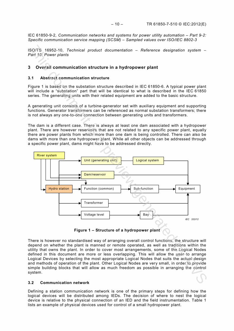
Figure 1 is based on the substation structure described in IEC 61850-6. A typical power plant will include a “substation” part that will be identical to what is described in the IEC 61850 series. The generating units with their related equipment are added to the basic structure.
A generating unit consists of a turbine-generator set with auxiliary equipment and supporting functions. Generator transformers can be referenced as normal substation transformers; there is not always any one-to-one connection between generating units and transformers.
The dam is a different case. There is always at least one dam associated with a hydropower plant. There are however reservoirs that are not related to any specific power plant, equally there are power plants from which more than one dam is being controlled. There can also be dams with more than one hydropower plant. While all other objects can be addressed through a specific power plant, dams might have to be addressed directly.
Figure 1 – Structure of a hydropower plant
There is however no standardised way of arranging overall control functions, the structure will depend on whether the plant is manned or remote operated, as well as traditions within the utility that owns the plant. In order to cover most arrangements, some of the Logical Nodes defined in this document are more or less overlapping. This will allow the user to arrange Logical Devices by selecting the most appropriate Logical Nodes that suits the actual design and methods of operation of the plant. Other Logical Nodes are very small, in order to provide simple building blocks that will allow as much freedom as possible in arranging the control system.
3.2 Communication network
Defining a station communication network is one of the primary steps for defining how the logical devices will be distributed among IEDs. The decision of where to nest the logical device is relative to the physical connection of an IED and the field instrumentation. Table 1 lists an example of physical devices used for control of a small hydropower plant.
River system
Hydro station
Unit (generating unit)
Function (common)
Dam/reservoir
Transformer
Voltage level Bay
Sub-function Equipment
Logical system
IEC 333/12
This document is a preview
generated by EVS