Embed Size (px)
Citation preview
This document has been prepared for the purposes of the PPP IN INFRASTRUCTURE RESOURCE CENTER FOR CONTRACTS, LAWS AND REGULATIONS (PPPIRC)
website. It is a sample document FOR REFERENCE PURPOSES ONLY and SHOULD NOT BE used as a "model". The inclusion of any legal materials on the PPPIRC website does not mean that they are in any way approved,
endorsed or recommended by the World Bank Group or its affiliates. Legal advice should be sought to determine whether a particular legal document is appropriate for any given project, and how the specific terms of the document
should be adapted to fit the circumstances of that project
PPP in Infrastructure Resource Center for Contracts, Laws and Regulations (PPPIRC) Reviewed: Robert Phillips, LEGPS http://www.worldbank.org/ppp February 2007
CONTRACT FOR THE DESIGN, CONSTRUCTION, FINANCE, OPERATION AND MAINTENANCE OF
HIGHWAY [ ] AS A TOLL HIGHWAY, INCLUDING ASSOCIATED DEVELOPMENTS AND
FACILITIES.
ANNEXURE II
ENGINEERING REQUIREMENTS
TABLE OF CONTENTS
LIST OF TENDER DOCUMENTS ............................................................................................................ 2
1. INTRODUCTION ................................................................................................................................. 4
2. ENGINEERING REQUIREMENTS ................................................................................................. 5
3. HIGHWAY PERFORMANCE REQUIREMENTS ..................................................................... 29
SCHEDULE 1 : PERFORMANCE BASED MAINTENANCE REQUIREMENTS
2
PPP in Infrastructure Resource Center for Contracts, Laws and Regulations (PPPIRC) Reviewed: Robert Phillips, LEGPS http://www.worldbank.org/ppp February 2007
LIST OF TENDER DOCUMENTS
VOLUME BOOK DESCRIPTION ANNEXURE
VOLUME 1 INVITATION TO TENDER AND
CONTRACTS
VOLUME 1 BOOK 1 INVITATION TO TENDER
VOLUME 1 BOOK 2 CONCESSION CONTRACT
VOLUME 1 BOOK 3 A SCOPE OF WORKS AND PROGRAMMES ANNEXURE I
VOLUME 1 BOOK 3 B ENGINEERING REQUIREMENTS ANNEXURE II
VOLUME 1 BOOK 3 C DESCRIPTION OF SITE ANNEXURE III
VOLUME 1 BOOK 3 D ENVIRONMENTAL REQUIREMENTS ANNEXURE IV
VOLUME 1 SOCIO ECONOMIC REQUIREMENTS AND
TRAINING
ANNEXURE V
VOLUME 1 INDEPENDENT ENGINEER AGREEMENT ANNEXURE VI
VOLUME 1 BOOK 3 E DESIGN AND CONSTRUCTION CONTRACT ANNEXURE VII
VOLUME 1 OPERATION AND MAINTENANCE
CONTRACT
ANNEXURE VIII
VOLUME 1 FORM OF OPERATIONS AND
MAINTENANCE BOND
ANNEXURE IX
VOLUME 1 FORM OF FINAL MAINTENANCE BOND ANNEXURE X
VOLUME 1 FORM OF RESOLUTIVE CONDITIONS
BOND
ANNEXURE XI
VOLUME 1 FORM OF OPERATIONS REPORT ANNEXURE XII
VOLUME 1 FORM OF CONSTRUCTION PROGRESS
REPORT
ANNEXURE XIII
VOLUME 1 BOOK 3 F FINANCIAL BASE CASE ANNEXURE XIV
VOLUME 1 TOLL STRATEGY AND TOLL TARIFFS ANNEXURE XV
VOLUME 1 HIGHWAY USAGE FEE ANNEXURE XVI
VOLUME 1 EQUITY CONTRIBUTION ANNEXURE XVII
VOLUME 1 INSURANCE REQUIREMENTS ANNEXURE XVIII
VOLUME 1 BOOK 3 G CONCESSIONAIRE DOCUMENTS OF
ASSOCIATION
ANNEXURE XIX
VOLUME 1 KEY PERSONNEL POSITIONS ANNEXURE XX
VOLUME 1 SHAREHOLDERS AGREEMENT ANNEXURE XXI
VOLUME 1 FORM OF ATTORNEYS AFFIRMATION ANNEXURE XXII
VOLUME 1 ASSOCIATED AGREEMENTS ANNEXURE XXIII
VOLUME 1 OVERLOADING ANNEXURE XXIV
VOLUME 1 DEED OF SURETYSHIP ANNEXURE XXV
3
PPP in Infrastructure Resource Center for Contracts, Laws and Regulations (PPPIRC) Reviewed: Robert Phillips, LEGPS http://www.worldbank.org/ppp February 2007
VOLUME 2 STANDARD SPECIFICATIONS
VOLUME 2 BOOK 1 STANDARD SPECIFICATIONS FOR
OPERATIONS AND MAINTENANCE:
GENERAL
VOLUME 2 BOOK 2 STANDARD SPECIFICATIONS FOR
OPERATIONS AND MAINTENANCE:
ELECTRICAL AND MECHANICAL
EQUIPMENT
VOLUME 2 BOOK 3 STANDARD SPECIFICATIONS FOR
OPERATIONS AND MAINTENANCE: TOLL
SYSTEM AND EMERGENCY
COMMUNICATIONS SYSTEM
VOLUME 2 BOOK 4 STANDARD SPECIFICATIONS FOR
OPERATIONS AND MAINTENANCE:
ELECTRONIC TOLL COLLECTION
VOLUME 3 INFORMATION DOCUMENTS
VOLUME 3 BOOK 1 HIGHWAY INFORMATION
VOLUME 3 BOOK 2 TRAFFIC INFORMATION
VOLUME 3 BOOK 3 DRAWINGS
VOLUME 3 BOOK 4 ENVIRONMENTAL SCOPING REPORT
VOLUME 3 BOOK 5 ADDENDUM TO ENVIRONMENTAL
SCOPING REPORT
VOLUME 3 BOOK 6 MACRO ECONOMIC ASSESSMENT
REPORT
4
PPP in Infrastructure Resource Center for Contracts, Laws and Regulations (PPPIRC) Reviewed: Robert Phillips, LEGPS http://www.worldbank.org/ppp February 2007
ROADS AUTHORITY
CONTRACT NO
FOR
THE DESIGN, CONSTRUCTION, FINANCE, OPERATION AND MAINTENANCE OF
HIGHWAY No* AS A TOLL HIGHWAY INCLUDING ASSOCIATED FACILITIES AND
DEVELOPMENTS.
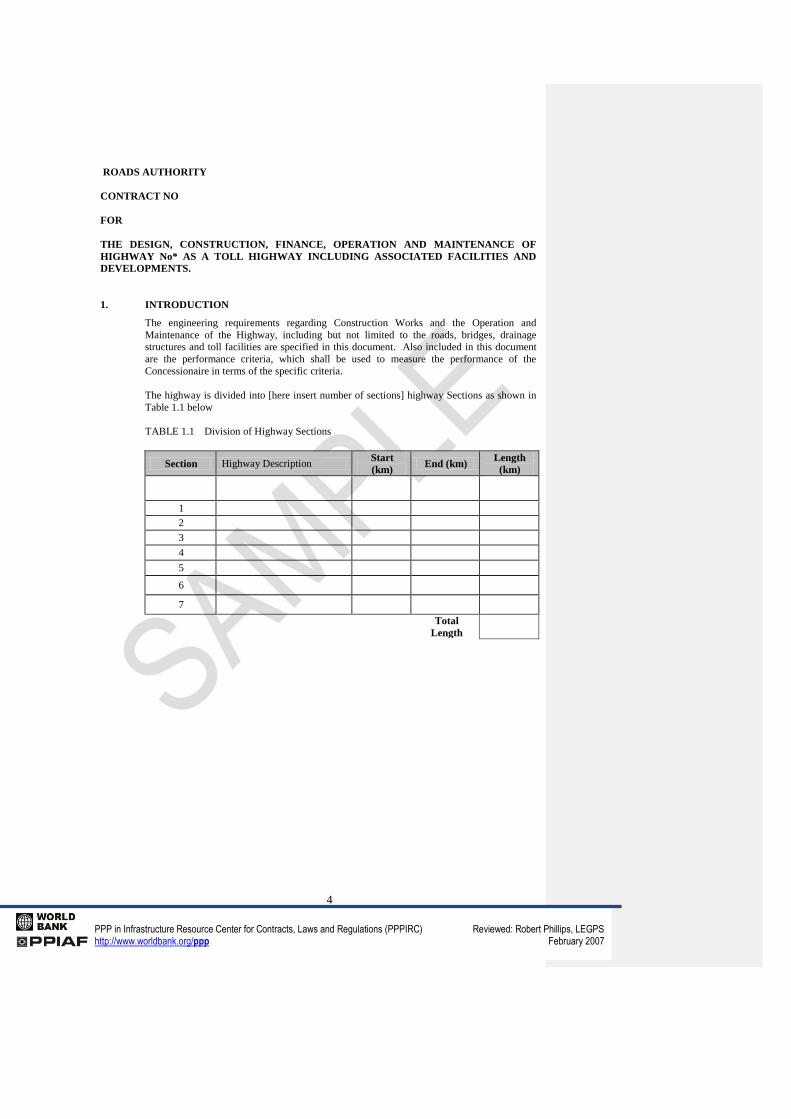
1. INTRODUCTION
The engineering requirements regarding Construction Works and the Operation and
Maintenance of the Highway, including but not limited to the roads, bridges, drainage
structures and toll facilities are specified in this document. Also included in this document
are the performance criteria, which shall be used to measure the performance of the
Concessionaire in terms of the specific criteria.
The highway is divided into [here insert number of sections] highway Sections as shown in
Table 1.1 below
TABLE 1.1 Division of Highway Sections
Section Highway Description Start
(km) End (km)
Length
(km)
1
2
3
4
5
6
7
Total
Length
5
PPP in Infrastructure Resource Center for Contracts, Laws and Regulations (PPPIRC) Reviewed: Robert Phillips, LEGPS http://www.worldbank.org/ppp February 2007
The Preliminary Design for the Initial Construction Works and the Additional Construction
Works shall be submitted to the Independent Engineer for review and recommendations and
to the Authority for approval in accordance with the provisions of the Concession Contract
and within the prescribed periods and subject to the requirements of subclause 2.1 of the
Concession Contract.
Each Detailed Design for the Initial Construction Works and Additional Construction Works
shall be submitted to the Authority for comment and to the Independent Engineer for
approval in accordance with the provisions of the Concession Contract and within the
prescribed periods and subject to the requirements of subclause 2.1 of the Concession
Contract.
Each completed part of the Construction Works and all services and activities required in
terms of an Operation and Maintenance Contract, shall be subject to review by the
Independent Engineer for compliance with these Engineering Requirements. Review and/or
approval by the Independent Engineer and/or the Authority of the aforementioned or any
other aspects of the Project shall not imply that the responsibilities and liabilities of the
Concessionaire are in any way reduced or assumed by the Independent Engineer or the
Authority.
The Authority reserves the right to request the Concessionaire to provide any data which it
has collected and used in determining when Additional Construction Works are to be carried
out, and to check such data if deemed necessary.
All Construction Works shall be in accordance with current (at the time of signing of the
Concession Contract) standard codes and specifications used by the Authority. Should the
use of other codes and specifications be required, such use shall be subject to the approval of
the Authority. The current versions and future amendments of the documents, codes and
specifications referred to herein, shall become the ruling documents, codes and
specifications for the duration of the Concession Contract.
2. ENGINEERING REQUIREMENTS
The requirements stipulated herein are to be used in addition to sound engineering
knowledge and good industry practice. A requirement must not be understood as an
"instruction" to the Concessionaire, who must at all times use its discretion and engineering
expertise to critically evaluate the requirement and, if it decides to deviate from or not to
abide by such requirement, the Concessionaire must motivate recommendations to the
Authority substantiating the reason for the required deviation. All deviations must be
approved by the Authority.
Comment [ID1]: [note-it would be possible to reduce the role of the Independent Engineer by developing a process of certification by or on behalf of the Concessionaire. The Concessionaire could be required to appoint or cause the Contractor to appoint a Designer who would be named as such and the Designer would have to issue a certificate that the design had been properly prepared. In addition and Independent Checker who was not employed by either the Contractor or the Designer could be required to check and certify the design of certain critical structures. Other design of structures of a less critical nature could be checked and certified by a separate team within the Designer. Similar arrangements could exist for construction. The role of the Independent Engineer in those circumstances would be more of an auditor but with the ability to carry out spot checks].
6
PPP in Infrastructure Resource Center for Contracts, Laws and Regulations (PPPIRC) Reviewed: Robert Phillips, LEGPS http://www.worldbank.org/ppp February 2007
2.1 Preliminary and Detailed Design Procedures and
Requirements
2.1.1 Introduction
All the design work undertaken by the Concessionaire in respect of the Concession Contract
shall comply with these procedures and requirements as well as with the requirements of
Annexure IV : Environmental Approval.
The design requirements are divided into the following two stages:
Preliminary Design
Detailed Design
2.1.2 Preliminary Design
The Preliminary Design shall, inter alia, include alignment, position of the road within the
Road Reserve, proposed road cross-sections, toll plaza location and layout, the influence on
land, environment and Utilities, to such detail that a review can be undertaken for
compliance with these requirements. The Preliminary Design shall also demonstrate design
standards clearly so as to enable the Authority and the Independent Engineer to assess the
design.
Due to varying road types and road conditions encountered, the Preliminary Design
requirements are categorised as follows:
Preliminary Designs for:
a. New Construction Works or Upgrade Works
b. Rehabilitation
c. Periodic Maintenance
d. Structures
e Toll plazas
f. Signalisation
g. Lighting
The content of the Preliminary Design submissions shall, inter alia, include the following:
2.1.2.1 New Construction Works or Upgrade Works
Submission of a preliminary design report containing the following:
a. Description of the works
b. Traffic analysis and traffic loading
c. Geometric design
d. Geotechnical evaluation
e. Preliminary materials report and pavement design with
preliminary materials investigation
f. Details regarding drainage design including positions and sizes of drainage structures
g. Information regarding Utilities
h. Details regarding land and additional Road Reserve requirements according to the
procedures as agreed to from time to time.
i. Traffic accommodation during construction
j. Details pertaining to the negotiations with landowners, for additional Road Reserve
requirements; only where applicable, and according to the procedures as agreed to
from time to time.
k. Consideration of environmental impacts.
Comment [ID2]: [note-this will depend upon the scope of consents and approvals acquired by the State or the Authority].
Comment [ID3]: [note-these will be project specific. In this case the project includes taking over and upgrade of existing roads or highways].
7
PPP in Infrastructure Resource Center for Contracts, Laws and Regulations (PPPIRC) Reviewed: Robert Phillips, LEGPS http://www.worldbank.org/ppp February 2007
l. Consideration of safety history for Upgrade Works
m. Drawings consisting of the following:
i. Layout drawings, where applicable, indicating horizontal alignment details,
intersections and accesses
ii. Longitudinal sections indicating proposed vertical alignments, if applicable
iii Typical road cross-sections and pavement details
n. Road furniture
2.1.2.2 Rehabilitation
Compilation and submission of a preliminary design report containing, inter alia, the
following:
a. Description of the works
b. Surface drainage on focus areas
c. History of inadequate drainage
d. Subsurface drainage (in distressed areas only)
e. Traffic accommodation during construction
f. Traffic and traffic loading analysis
g. Applicable functional performance indices
h. Consideration of safety history
i. Drawings consisting of the following:
i. Typical road cross-sections with pavement details
ii. Summary of pavement condition
iii. Summary of pavement rehabilitation measures including
intersections and accesses
2.1.2.3 Periodic Maintenance
Compilation and submission of a preliminary design report containing the following:
a. Description of the works inclusive of a:
i. Summary of pavement condition
ii. Summary of maintenance measures
b. Traffic accommodation during construction
c. Drawings, when applicable, to be included in the
design report
2.1.2.4 Structures
Work on structures is divided into:
New and Upgrade Works
Repair works
2.1.2.4.1 New and Upgrade Works:
Compilation and submission of a preliminary design report containing
inter alia the following:
a. Description of the works
b. Traffic analysis if not already covered elsewhere
c. Preliminary foundation investigation
d. Hydraulic calculations or confirmation of previous hydraulic
calculations in the case of bridge widening
e. Conceptual design
f. Accommodation of Utilities where applicable
g. Requirements for additional Road Reserve and details of
8
PPP in Infrastructure Resource Center for Contracts, Laws and Regulations (PPPIRC) Reviewed: Robert Phillips, LEGPS http://www.worldbank.org/ppp February 2007
negotiations with land owners if applicable, according to the procedures as agreed to
from time to time
h. Traffic accommodation during construction
i. Environmental impact details
j. Diagnostic Survey Report if appropriate.
k. Bridge schedule [ here insert relevant reference document for bridge design]
Waterway structures for which the design flood exceeds [here insert criterion] shall be
regarded as bridges.
2.1.2.4.2 Repair works:
Compilation and submission of a preliminary design report containing, inter alia, the
following:
a. Description of the works
b. Traffic analysis if not already covered elsewhere
c. Conceptual design
d. Accommodation of traffic where necessary
e. Reference to Bridge Management System if it has been
inspected
f. Reference to diagnostic survey reports if appropriate
g. Drawings consisting of conceptual designs as applicable
2.1.2.5 Toll Plazas
Submission of a preliminary design report containing the following:
a. Description of the works
b. Traffic analysis – including peaks in both directions
c. Land acquisition requirements and negotiation with landowners if applicable
according to the procedures as agreed to from time to time.
d. Conceptual designs for plazas and systems
e. Preliminary foundation investigation report
f. Services supply arrangements
g. Traffic accommodation during construction
h. Environmental impact details and mitigation measures as required by legislation.
i. Preliminary Design drawings including:
ii. Plaza layout and lane configuration drawings
iii. Longitudinal sections
iv. Typical cross sections
2.1.2.6 Signalisation
Submission of a preliminary design report containing, inter alia, the
following;
a. Description of the works
b. Traffic analysis
c. Intersection and signal layout
d. Timing plan
9
PPP in Infrastructure Resource Center for Contracts, Laws and Regulations (PPPIRC) Reviewed: Robert Phillips, LEGPS http://www.worldbank.org/ppp February 2007
2.1.2.7 Lighting
Submission of a preliminary design report containing, inter alia, the
following:
a. Description of the works
b. Lighting layout
c. Equipment details (e.g. poles, luminaries etc.)
2.1.2.8 General
Information about consultation on technical and socio-economic matters with Relevant
Authorities and other parties concerned. Details of interviews held with affected land
owners including contact information and agreements reached regarding access
arrangements, accommodation of services as well as other information pertaining to the
Preliminary Design enabling the Independent Engineer to approve such Preliminary
Design.
2.1.3 Detailed Design
The Detailed Design is the preparation of detailed working drawings, project specifications
and the appropriate documentation for construction purposes. After the Initial Construction
Period, the Detailed Design for Additional Construction Works shall also include a schedule
of quantities and rates and prices for those Construction Works.
The Detailed Design of the Highway shall include, but will not be limited to, the following:
a. All working drawings, schedules and designs required for the Construction Works in
accordance with the applicable standards and codes of procedure listed herein.
b. Project specifications and other provisions required for the Construction Works.
c. Schedule of quantities with rates and prices for Additional Construction Works.
d. Design changes to the drawings, to comply with the Engineering Requirements or as
agreed by the Independent Engineer.
e. A detailed geotechnical report.
f. A detailed materials report.
g. Design drawing(s) for bridges consisting of a general arrangement drawing or
drawings as provided for under [ here insert relevant reference to appropriate Code of
Procedure for the Planning and Design of Structures] shall be submitted for approval
prior to the commencement of the Detail Design. All approval requirements of other
relevant authorities shall be adhered to.
h. Requirements for land acquisition related to borrow areas and
temporary accommodation of traffic and details of negotiations with land owners if
applicable, according to the procedures as agreed to from time to time.
i. Traffic analysis and traffic loading.
j. Compliance with environmental requirements.
2.1.4 Submission of Preliminary Designs: Format and Procedure
The Concessionaire shall prepare six (6) copies of the Preliminary Design, of which four (4)
copies shall be submitted to the Independent Engineer and two (2) copies shall be submitted
to the Authority. The number of copies required may be varied as agreed to on a case-by-
case basis. These submissions to the Independent Engineer and to the Authority shall be
done simultaneously and in accordance with the agreed Preliminary Design procedure. The
copies of the document shall comply with the following requirements:
a. Reports of A4 size, printed on good quality 80 gsm paper and suitably bound in book
format.
Comment [ID4]: [note-this again will be project specific. Consideration should be give to allowing the Independent Engineer and Authority to read only access to the hardware on which CAD is run].
10
PPP in Infrastructure Resource Center for Contracts, Laws and Regulations (PPPIRC) Reviewed: Robert Phillips, LEGPS http://www.worldbank.org/ppp February 2007
b. Drawings reduced to A2 size and printed on 80 gsm paper, suitably bound in book
format.
Covers and titles of documents shall be as agreed upon between the Authority and the
Concessionaire.
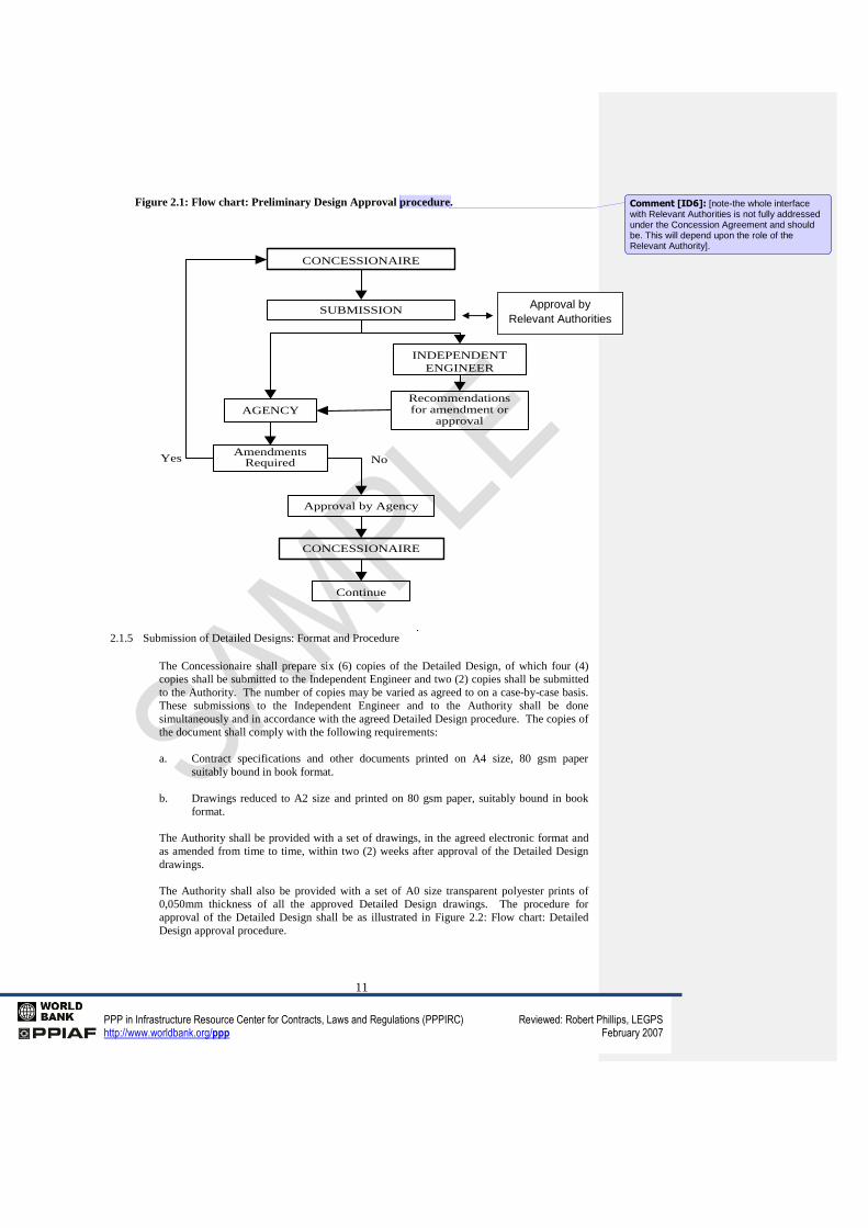
The procedure for approval of the Preliminary Design shall be as illustrated in Figure 2.1. The
Independent Engineer shall review the Preliminary Design and make recommendations to the
Authority for amendments or approval. The Authority shall inform the Concessionaire within
twenty-one (21) Business Days whether amendments are required or whether the Preliminary
Design has been approved.
If the Authority fails to inform the Concessionaire of the approval of the Preliminary Design,
or of the amendments required to any part of the Preliminary Design, by the end of twenty-one
(21) Business Days of its submission (by hand) to the Authority, the Concessionaire shall give
the Authority notice that the Preliminary Design will be deemed to be approved, should no
comments be received within three (3) Business Days from the date of delivery by hand of the
said notice to the Authority.
Subject to the preceding clause, the programme for submission of the Preliminary Designs
must make provision for the submission of a maximum of three (3) submissions per cycle of
eight (8) Business Days. Should more than three (3) Preliminary Designs be submitted to the
Authority for approval within a single eight (8) Business Day period, then the dates of
submission of the submissions in excess of three (3) will be deemed to be submitted in the
period following the one in which they were actually submitted.
If the Authority refers the Preliminary Design back to the Concessionaire for amendments, the
approval procedure as set out herein shall apply to the amended Preliminary Design.
Prior to the submission of the Preliminary Design to the Independent Engineer and the
Authority, the Concessionaire shall ensure that the Operations and Maintenance Contractors
have been given the opportunity to review the Preliminary Design and give their comments
and recommendations.
Approval of the Preliminary Design shall not relieve the Concessionaire of its liabilities and
obligations under the Concession Contract, and it shall not relieve the Contractor or the
Operator of any of their liabilities and obligations under the Design and Construction Contract
and the Operation and Maintenance Contract respectively.
Comment [ID5]: [note-the contractual provisions relating to the approvals process are set out in the Concession Contract. It would be better that contractual terms are dealt with in the body of the Concession Contract and not repeated or added to in the technical annexures].
11
PPP in Infrastructure Resource Center for Contracts, Laws and Regulations (PPPIRC) Reviewed: Robert Phillips, LEGPS http://www.worldbank.org/ppp February 2007
Figure 2.1: Flow chart: Preliminary Design Approval procedure.
2.1.5 Submission of Detailed Designs: Format and Procedure
The Concessionaire shall prepare six (6) copies of the Detailed Design, of which four (4)
copies shall be submitted to the Independent Engineer and two (2) copies shall be submitted
to the Authority. The number of copies may be varied as agreed to on a case-by-case basis.
These submissions to the Independent Engineer and to the Authority shall be done
simultaneously and in accordance with the agreed Detailed Design procedure. The copies of
the document shall comply with the following requirements:
a. Contract specifications and other documents printed on A4 size, 80 gsm paper
suitably bound in book format.
b. Drawings reduced to A2 size and printed on 80 gsm paper, suitably bound in book
format.
The Authority shall be provided with a set of drawings, in the agreed electronic format and
as amended from time to time, within two (2) weeks after approval of the Detailed Design
drawings.
The Authority shall also be provided with a set of A0 size transparent polyester prints of
0,050mm thickness of all the approved Detailed Design drawings. The procedure for
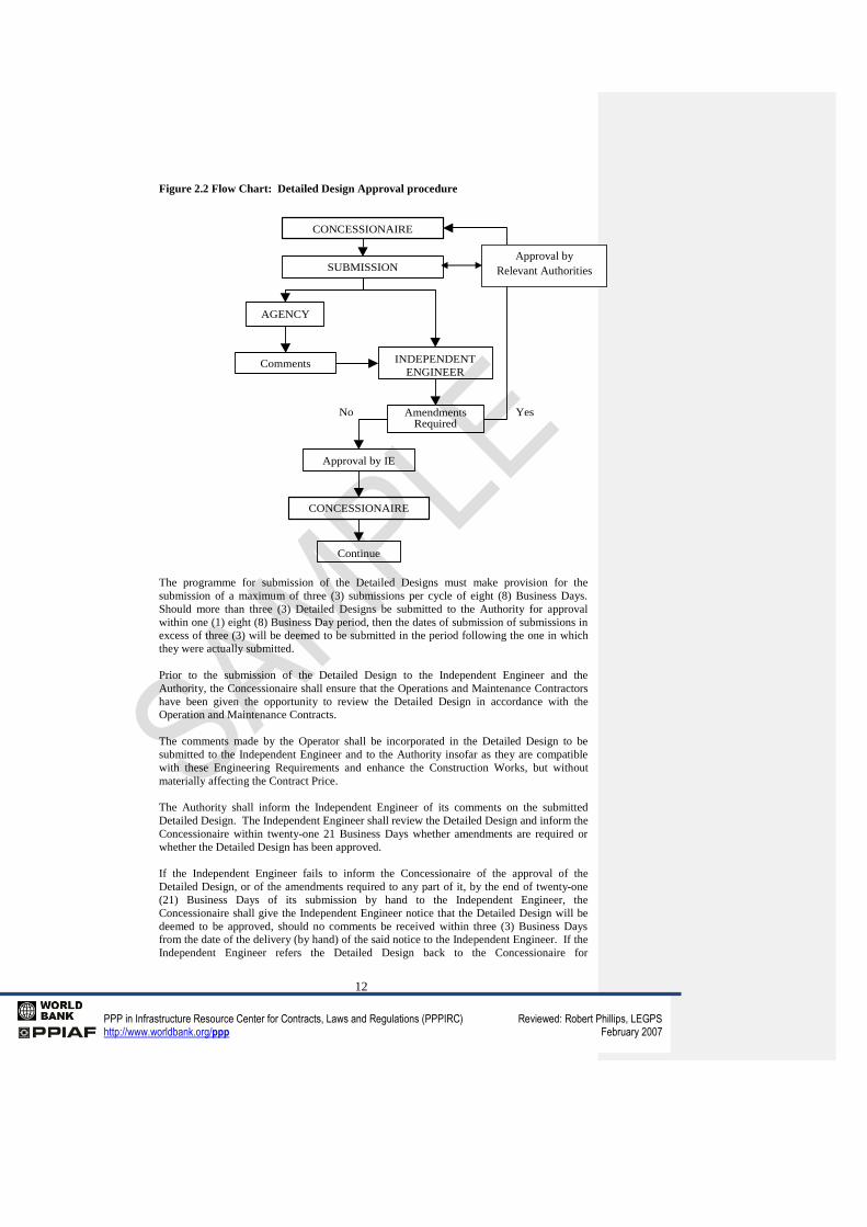
approval of the Detailed Design shall be as illustrated in Figure 2.2: Flow chart: Detailed
Design approval procedure.
CONCESSIONAIRE
SUBMISSION
INDEPENDENT
ENGINEER
Recommendationsfor amendment or
approvalAGENCY
AmendmentsRequiredYes
Approval by Agency
CONCESSIONAIRE
Continue
No
Approval by
Relevant Authorities
Comment [ID6]: [note-the whole interface with Relevant Authorities is not fully addressed under the Concession Agreement and should be. This will depend upon the role of the Relevant Authority].
12
PPP in Infrastructure Resource Center for Contracts, Laws and Regulations (PPPIRC) Reviewed: Robert Phillips, LEGPS http://www.worldbank.org/ppp February 2007
Figure 2.2 Flow Chart: Detailed Design Approval procedure
The programme for submission of the Detailed Designs must make provision for the
submission of a maximum of three (3) submissions per cycle of eight (8) Business Days.
Should more than three (3) Detailed Designs be submitted to the Authority for approval
within one (1) eight (8) Business Day period, then the dates of submission of submissions in
excess of three (3) will be deemed to be submitted in the period following the one in which
they were actually submitted.
Prior to the submission of the Detailed Design to the Independent Engineer and the
Authority, the Concessionaire shall ensure that the Operations and Maintenance Contractors
have been given the opportunity to review the Detailed Design in accordance with the
Operation and Maintenance Contracts.
The comments made by the Operator shall be incorporated in the Detailed Design to be
submitted to the Independent Engineer and to the Authority insofar as they are compatible
with these Engineering Requirements and enhance the Construction Works, but without
materially affecting the Contract Price.
The Authority shall inform the Independent Engineer of its comments on the submitted
Detailed Design. The Independent Engineer shall review the Detailed Design and inform the
Concessionaire within twenty-one 21 Business Days whether amendments are required or
whether the Detailed Design has been approved.
If the Independent Engineer fails to inform the Concessionaire of the approval of the
Detailed Design, or of the amendments required to any part of it, by the end of twenty-one
(21) Business Days of its submission by hand to the Independent Engineer, the
Concessionaire shall give the Independent Engineer notice that the Detailed Design will be
deemed to be approved, should no comments be received within three (3) Business Days
from the date of the delivery (by hand) of the said notice to the Independent Engineer. If the
Independent Engineer refers the Detailed Design back to the Concessionaire for
CONCESSIONAIRE
AmendmentsRequired
SUBMISSION
INDEPENDENT
ENGINEERComments
AGENCY
Approval by IE
CONCESSIONAIRE
Continue
YesNo
Approval by
Relevant Authorities
13
PPP in Infrastructure Resource Center for Contracts, Laws and Regulations (PPPIRC) Reviewed: Robert Phillips, LEGPS http://www.worldbank.org/ppp February 2007
amendments, the approval procedure as set out above shall apply to the amended Detailed
Design.
Approval of the Detailed Design shall not relieve the Concessionaire of its liabilities and
obligations under the Concession Contract and it shall not relieve the Contractor or the
Operator of any of their obligations and liabilities under the Design and Construction
Contract and the Operation and Maintenance Contract respectively.
The Highway Sections (or portions or combinations thereof) or Toll Plaza(s), which are to be
the subject of a particular Detailed Design, shall be realistic portions of work appropriate to
a single Detailed Design, and shall be agreed with the Independent Engineer.
A Detailed Design for roadworks may be submitted for approval with the Detailed Design of
some or all of the bridges and structures being excluded. The Independent Engineer may
approve such a Detailed Design subject to the express provisions that no work may
commence on any structure until the Detailed Design of that structure has been approved in
accordance with the procedures outlined herein and that any changes which may be required
to the approved Detailed Design of roadworks or completed construction works related to
the approved Detailed Design for the roadworks shall be entirely for the account of the
Concessionaire. The Concessionaire shall in such cases agree with the Independent
Engineer a programme for submission of the outstanding Detailed Designs for bridges and
structures.
2.1.6 As-built drawings and construction report
Within three (3) months after the completion of each phase of the Construction Works on a
portion of work which is the subject of a single Detailed Design, the Concessionaire shall
provide the Independent Engineer, copy to the Authority, with a Construction Completion
Report, a schedule of fixed assets and as-built drawings, in hard copy as well as in the agreed
electronic format, and as amended from time to time and all such other records as may be
required and agreed upon. Material as-built records shall be submitted in the same manner
as the as-built drawings within six weeks of each section being completed.
2.2 Geometric Design Requirements
2.2.1 Standard Procedures, Design Manuals and Standard Drawings.
The requirements set forth in the latest version of the documents listed below, or any new
document that may be adopted by the Authority, shall apply where applicable:
a. A Code on Geometric Design of Highways and Streets
b. Highway Capacity Manual .
c. Transportation and Land Development Engineering;
d. Basic Planning of Roads and Bridges.
e. Manual for the Preparation of Detailed Geometric Design Plans for National
Highways.
f. Manual for Final Design Drawings for National Highways
g. Drainage Manual,
h. Geometric Design of non National Highways.
i. Road Traffic Signs Manual.
Comment [ID7]: [note-the relevant manuals ,policies or codes should be inserted in place of the list in 2.2.1].
14
PPP in Infrastructure Resource Center for Contracts, Laws and Regulations (PPPIRC) Reviewed: Robert Phillips, LEGPS http://www.worldbank.org/ppp February 2007
j. Standard and typical plans of the Authority as revised from time to time.
k. Urban Transport Guidelines
l. Code of practice for the lighting of National Highways
2.2.2 Requirements
2.2.2.1 General Principles
The engineering design of the project shall be based on the application of the requirements
herein as well as good industry practice. Any variation from the requirements specified
herein shall be subject to the approval of the Authority and the Concessionaire and must be
motivated in detail to the Authority by the Concessionaire. The requirements specified
herein may be altered as agreed upon in writing between the Authority and the
Concessionaire, dependent on future technological advances in the field of road engineering.
The geometric development of the Highway is to be based on the following:
The requirements specified in this Annexure
Standards of the existing roads
Rural conditions and classification
Urban conditions and classification
2.2.2.2 Geometry
The geometry of the Highway shall be upgraded for the following reasons:
Safety of road users
Capacity improvements
Elimination of unacceptable operational characteristics
Non-conformance with minimum geometric standards.
The design shall be in accordance with the documents specified herein or as specified in this
Volume. Wherever discrepancies arise, this Volume shall take precedence.
a. Classification of Highway Sections
The following general road classification shall apply to Highway Sections:
TABLE 2.1: Classification of Highway Sections
ROAD CLASSIFICATION HIGHWAY SECTIONS
Comment [ID8]: [note-complete in accordance with project requirements].
15
PPP in Infrastructure Resource Center for Contracts, Laws and Regulations (PPPIRC) Reviewed: Robert Phillips, LEGPS http://www.worldbank.org/ppp February 2007
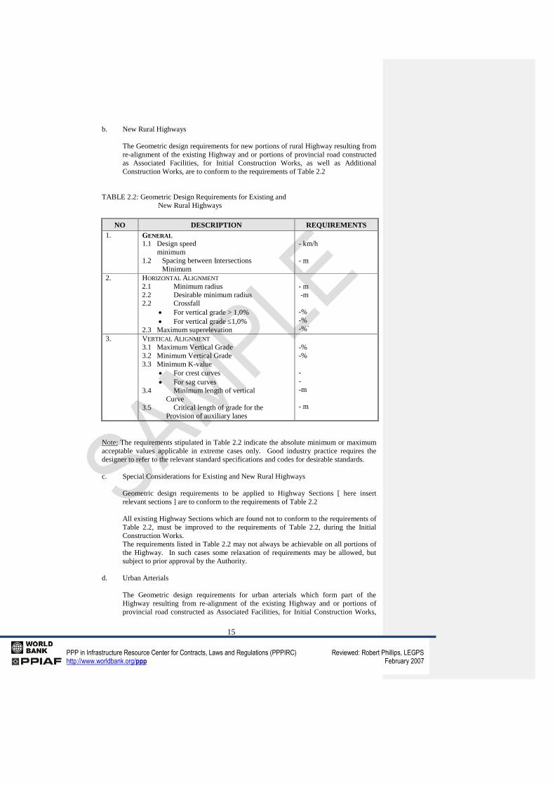
b. New Rural Highways
The Geometric design requirements for new portions of rural Highway resulting from
re-alignment of the existing Highway and or portions of provincial road constructed
as Associated Facilities, for Initial Construction Works, as well as Additional
Construction Works, are to conform to the requirements of Table 2.2
TABLE 2.2: Geometric Design Requirements for Existing and
New Rural Highways
NO DESCRIPTION REQUIREMENTS
1. GENERAL
1.1 Design speed
minimum
1.2 Spacing between Intersections
Minimum
- km/h
- m
2. HORIZONTAL ALIGNMENT
2.1 Minimum radius
2.2 Desirable minimum radius
2.2 Crossfall
For vertical grade > 1,0%
For vertical grade 1,0%
2.3 Maximum superelevation
- m
-m
-%
-%
-%`
3. VERTICAL ALIGNMENT
3.1 Maximum Vertical Grade
3.2 Minimum Vertical Grade
3.3 Minimum K-value
For crest curves
For sag curves
3.4 Minimum length of vertical
Curve
3.5 Critical length of grade for the
Provision of auxiliary lanes
-%
-%
-
-
-m
- m
Note: The requirements stipulated in Table 2.2 indicate the absolute minimum or maximum
acceptable values applicable in extreme cases only. Good industry practice requires the
designer to refer to the relevant standard specifications and codes for desirable standards.
c. Special Considerations for Existing and New Rural Highways
Geometric design requirements to be applied to Highway Sections [ here insert
relevant sections ] are to conform to the requirements of Table 2.2
All existing Highway Sections which are found not to conform to the requirements of
Table 2.2, must be improved to the requirements of Table 2.2, during the Initial
Construction Works.
The requirements listed in Table 2.2 may not always be achievable on all portions of
the Highway. In such cases some relaxation of requirements may be allowed, but
subject to prior approval by the Authority.
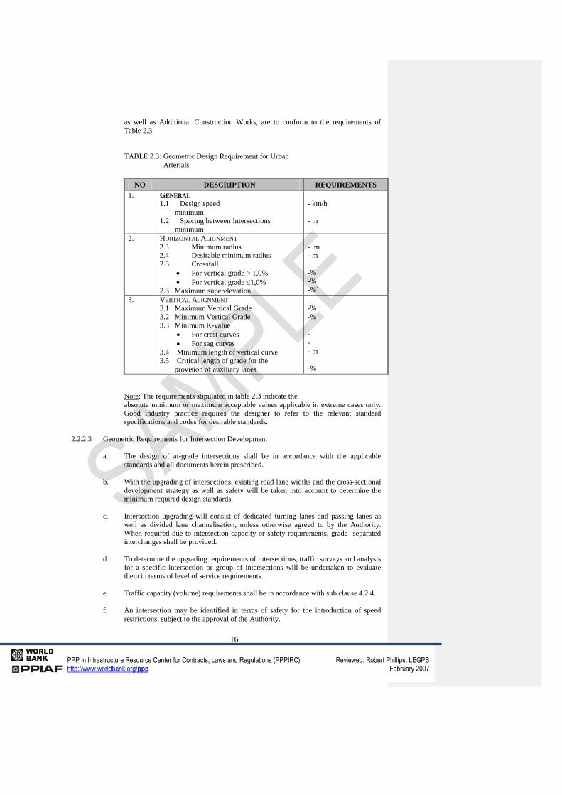
d. Urban Arterials
The Geometric design requirements for urban arterials which form part of the
Highway resulting from re-alignment of the existing Highway and or portions of
provincial road constructed as Associated Facilities, for Initial Construction Works,
16
PPP in Infrastructure Resource Center for Contracts, Laws and Regulations (PPPIRC) Reviewed: Robert Phillips, LEGPS http://www.worldbank.org/ppp February 2007
as well as Additional Construction Works, are to conform to the requirements of
Table 2.3
TABLE 2.3: Geometric Design Requirement for Urban
Arterials
NO DESCRIPTION REQUIREMENTS
1. GENERAL
1.1 Design speed
minimum
1.2 Spacing between Intersections
minimum
- km/h
- m
2. HORIZONTAL ALIGNMENT
2.3 Minimum radius
2.4 Desirable minimum radius
2.3 Crossfall
For vertical grade > 1,0%
For vertical grade 1,0%
2.3 Maximum superelevation
- m
- m
-%
-%
-%`
3. VERTICAL ALIGNMENT
3.1 Maximum Vertical Grade
3.2 Minimum Vertical Grade
3.3 Minimum K-value
For crest curves
For sag curves
3.4 Minimum length of vertical curve
3.5 Critical length of grade for the
provision of auxiliary lanes
-%
-%
-
-
- m
-%
Note: The requirements stipulated in table 2.3 indicate the
absolute minimum or maximum acceptable values applicable in extreme cases only.
Good industry practice requires the designer to refer to the relevant standard
specifications and codes for desirable standards.
2.2.2.3 Geometric Requirements for Intersection Development
a. The design of at-grade intersections shall be in accordance with the applicable
standards and all documents herein prescribed.
b. With the upgrading of intersections, existing road lane widths and the cross-sectional
development strategy as well as safety will be taken into account to determine the
minimum required design standards.
c. Intersection upgrading will consist of dedicated turning lanes and passing lanes as
well as divided lane channelisation, unless otherwise agreed to by the Authority.
When required due to intersection capacity or safety requirements, grade- separated
interchanges shall be provided.
d. To determine the upgrading requirements of intersections, traffic surveys and analysis
for a specific intersection or group of intersections will be undertaken to evaluate
them in terms of level of service requirements.
e. Traffic capacity (volume) requirements shall be in accordance with sub clause 4.2.4.
f. An intersection may be identified in terms of safety for the introduction of speed
restrictions, subject to the approval of the Authority.
17
PPP in Infrastructure Resource Center for Contracts, Laws and Regulations (PPPIRC) Reviewed: Robert Phillips, LEGPS http://www.worldbank.org/ppp February 2007
g. Minimum spacing between intersections will also depend on terrain and sight
distance. Sight distance calculations at intersections shall be in accordance with the
G2 Manual requirements for "stopping" sight distance.
h. The minimum curve radius for intersections on curves shall be R = [here insert
relevant distance ]. Intersections on curves with radius less than R must be well
motivated, and each case will be judged on its own merits by the Authority. Care
must be exercised not to exceed a [ here insert relevant percentage]% superelevation
of the main road at any intersection.
i. In special cases, if well motivated by the Concessionaire and accepted by the
Authority, the improvement of existing intersections to comply with the
requirements, could be postponed from the Initial Construction period to a later date
in the Concession Period, provided that the said improvement shall take place during
the first rehabilitation activity that includes the reconstruction of the base course of
the existing road and the safety of the intersection is monitored continuously.
j. Should the intersection prove to be unsafe, immediate remedial action shall be taken
to improve the intersection to the required standards.
k. Where dual carriageways or multi-lane facilities have to be established in an urban
environment without grade-separated interchanges, signalised intersections shall be
suitably spaced in terms of applicable design standards or traffic capacity
requirements. In such cases property access will have to be reduced by the
construction of Associated Facilities such as service roads or collector roads parallel
to the Highway. This is to be agreed upon with Relevant Authorities where
applicable.
l. The upgrading of intersections in an urban environment on the Highway (primary or
secondary arterial) will be by lane addition in terms of the strategy described below:
i. The spacing of intersections (or accesses) shall be suitable for co-ordination of
signalised intersections when required for capacity reasons.
ii. Where required, the crossing of the median on a four or more lane road shall
be limited to identified positions on the Highway approved by the Authority.
iii. Existing access points may be closed and diverted via parallel service and/or
collector roads.
m. The signal timing of the signalised intersections will be agreed with the local
authority. The Concessionaire will be responsible for operating and maintaining the
traffic signals
n. All intersections will be provided with lighting as specified in the latest version of
[here insert relevant Code of Practice for the Lighting of National Highways ]. The
Concessionaire will be responsible for operating and maintaining the lighting.
2.2.2.4 Geometric Requirements for Interchange Development
Interchanges shall be upgraded to ensure compliance with the relevant clauses in the
Concession Contract.
The design of interchanges shall be in accordance with the applicable standards and all
documents herein prescribed.
Geometric standards for interchanges will also be determined by the applicable Relevant
Authority's classification of the crossroad subject to the Authority’s approval.
Comment [ID9]: [note-see previous comment as to issue of Relevant Authorities].
18
PPP in Infrastructure Resource Center for Contracts, Laws and Regulations (PPPIRC) Reviewed: Robert Phillips, LEGPS http://www.worldbank.org/ppp February 2007
2.2.2.5 Cross-Sections and Cross-Section Development Strategy
The cross section of the Highway shall be upgraded to ensure compliance with the relevant
clauses in the Concession Contract. The existing and proposed cross-sections as well as the
development strategy required are given in Annexure I : Scope of Works and Programmes as
well as in the G2 Manual and may be revised after consultation between the Authority and
the Concessionaire if so warranted in special cases such as Road Reserve restrictions,
alternative upgrading requirements, etc.
2.2.2.6 Geometric Requirements for Toll Plazas
Suitable transition between the road cross-section and toll plaza cross section shall be
established in the vicinity of the toll plaza, all subject to the approval of the Authority.
Details for the design of the Toll Plazas are specified under
Item 2.5.
Geometric Requirements for Associated Facilities and
Developments
Standards shall comply with the design codes specified herein, and with the requirements of
the Relevant Authorities, unless otherwise agreed.
2.3 Design Requirements for Bridges and Drainage Structures
The Concessionaire shall take into account the following requirements regarding the design
of bridges and drainage structures.
2.3.1 Bridges
2.3.1.1 Standard Procedures and Design Manuals
[Here insert details of relevant codes or manuals].
It is incumbent on the Concessionaire to provide the Authority with an aesthetically pleasing
and effective practical solution by taking cognisance of all factors, including environmental
factors and other factors not directly connected to the structural integrity, such as concrete
durability, that may have an influence on the design of the structure.
2.3.1.2 Requirements
a. Width of bridges
The width of bridges as measured between the inside edges of the balustrades shall be
as follows:
i. For multi-lanes, [here insert details].
ii. For over passing crossroads [here insert details].
iii. For agricultural overpasses [here insert details].
iv. For agricultural underpasses[here insert details].
v. For ramps and loops [ here insert details].
vi. For under passing crossroads minimum clear shoulder widths [here insert
details].
19
PPP in Infrastructure Resource Center for Contracts, Laws and Regulations (PPPIRC) Reviewed: Robert Phillips, LEGPS http://www.worldbank.org/ppp February 2007
vii. For pedestrian bridges a minimum clear width of [here insert details].
b. Clearance
i Vertical clearance
Minimum vertical clearances for road over rail bridges shall be :
[ here insert details]
The minimum vertical clearance for new structures shall be
[here insert details].
The minimum vertical clearance on all agricultural underpasses used by heavy
vehicles shall be [ here insert details].
ii Horizontal clearance
The horizontal clearances for road over rail bridges shall be as follows:[here insert
details]
c. Width of Sidewalks
[ here insert details]
2.3.2 Drainage structures
2.3.2.1 Standard Procedures and Design Manuals
The requirements set forth in the documents listed below shall apply:
[here insert details]
2.3.2.2 Requirements
The requirements shall be those specified in the applicable manuals and codes of the [host
country] as well as the following:
[here insert details]
a. Design Flood Return Periods
b. In urban areas the road cross-section may be used as a part of
the drainage discharge system for higher flood frequencies.
c. The drainage design criteria shall always be tested in terms of
risk of adjoining property damage and be accordingly adjusted where required.
d. If existing property is damaged repeatedly by the assumption of
short design flood return periods, these shall be increased by period commensurate
with the damage that could ensue.
e. In urban areas the use of large open channel drainage systems
are discouraged. In special cases the Concessionaire may motivate the use of such
systems to the Authority. Special attention shall be given to safety and security
aspects of the design.
f. In the case of a bridge which is designed to pass the design
flood below the soffit of the super-structure its stability shall also be checked to be
safe when subjected to the regional maximum flood (RMF).
20
PPP in Infrastructure Resource Center for Contracts, Laws and Regulations (PPPIRC) Reviewed: Robert Phillips, LEGPS http://www.worldbank.org/ppp February 2007
2.3.3 Livestock Crossings
2.3.3.1 Scope
At grade crossing of livestock is not permitted.
Design Requirements for Livestock Culverts /Agricultural
Underpasses
a. General Requirements
Since these structures pass under the road foundation, they must be structurally
capable of carrying the imposed live and dead loads, and steep enough so that
drainage is not impeded. They must be easily usable by the type of livestock and
agricultural equipment for which they are provided.
b. Design Requirements
The design of livestock culverts and agricultural underpasses shall be in accordance
with the applicable standards and all documents herein prescribed.
i. Structural Design
[ here insert details]
ii. Drainage Design
[ here insert details]
iii. Culvert size
[ here insert details]
iv. Finishing of culvert floors
[ here insert details]
v. Finishing of culvert approaches
[here insert details].
2.3.4 Requirements for Concrete Durability in Structures
Additional to the normal concrete tests, concrete durability tests for all drainage structures,
livestock culverts and bridges will be done to establish base factors for the concrete.
Before the construction starts, the Concessionaire will provide a testing program for
approval. As a guide it will be expected that for a typical road-over-road bridge, one test
will be done on the deck soffit, at least one test on the columns and one on each abutment.
Each test will consist of 3 cores taken at random positions. Results have to be handed over
to the Authority in a prescribed format directly after completion of the specific structures on
a Highway Section. Cover meter tests should cover at least *m2 for every **m
2 exposed.
21
PPP in Infrastructure Resource Center for Contracts, Laws and Regulations (PPPIRC) Reviewed: Robert Phillips, LEGPS http://www.worldbank.org/ppp February 2007
To ensure that the concrete has been placed, compacted and cured correctly, a nominated
laboratory shall carry out the following tests after 28 days in terms of the latest specifications
of [ here insert details]:
a. Water sorptivity
b. Oxygen Permeability
c. Rapid chloride conductivity (only to be applied in an
environment subjected to a salt laden atmosphere)
d. Measure the depth of concrete cover
Results obtained in accordance with the specified test methods, shall be assessed in terms of
the ranges specified by [ here insert details]. These values are guideline values, which will
be refined and agreed during the Concession Period.
The Concessionaire will indicate the positions at which the cores shall be extracted on site.
2.4 Pavement and Geotechnical Design Requirements
2.4.1 Scope
The requirements contained in this clause cover road pavement design, cut and fill stabilities
and road building materials for new works, upgrades and rehabilitation. This clause does not
contain geotechnical requirements for bridges or other structures. In general, the provisions
[ here insert details of the Code of Procedure to be followed for bridges and structures.
The Concessionaire shall take into account the following requirements and standards
regarding road pavement and geotechnical designs.
2.4.2 Road Pavement Designs
The design codes and methods currently used by and acceptable to the Authority are listed
below but do not exclude the use of any other recognised or innovative design method(s).
[here insert details].
2.4.3 Cut and fill design
It is a general requirement that the stability (subsurface and other) of cuts and fills shall be
properly investigated and designed. In doing so the Concessionaire shall procure that the
services of a reputable and professional geotechnical engineer be used.
The minimum factor of safety for the stability of cuts and fills shall be **. The stability of
cuts and fills shall be certified safe in all respects by a professional geotechnical engineer.
2.4.4 Road building materials
The Concessionaire shall ensure that all materials are compatible with the environment and
health regulations and practices. The procurement and quality of road building materials
shall be the responsibility of the Concessionaire including the acquisition of a mining permit
in the event of material obtained from a non-commercial source. The following
standards/guidelines are generally used by the Authority:
[here insert details]
22
PPP in Infrastructure Resource Center for Contracts, Laws and Regulations (PPPIRC) Reviewed: Robert Phillips, LEGPS http://www.worldbank.org/ppp February 2007
2.5 Design Requirements for Toll Plazas
2.5.1 Scope
The design of toll plazas includes the following disciplines:
a. Civils (geometric alignments, pavement structures, drainage,
water supply, sewerage, etc.)
b. Structures (toll islands, canopies, tunnels, foundations,
manholes, etc.)
c. Buildings (plaza buildings, plant buildings, toll booths etc.,
inclusive of all internal Utilities)
d. Electrical (area lighting, uninterrupted power supply (UPS),
generators and lightning protection)
e. Mechanical (fresh air supply, pressurised air supply to toll
booths, air-conditioning, heating, etc.)
f. Electronic lane equipment (toll collection equipment, toll
collection control equipment, traffic event logger (TEL), etc.)
g. Management Information System (MIS) (this includes the
computer hardware, computer software packages and MIS
programmes.)
2.5.2 Standard Procedures and Specifications
The standard procedures for geometric design, pavement design, geotechnical design,
structural design and drainage design as covered by the preceding clauses as well as the
latest version of the following additional publications shall apply:
[here insert details].
2.5.3 Requirements for Civil and Structural Works
Notwithstanding the requirements given elsewhere the following shall
apply:
a. Vertical canopy clearance: ** m minimum
b. Highway approach gradient: *% maximum for a distance of * km
on each side of the toll plaza measured from the tollbooths
c. Longitudinal gradient for mainline plazas: **% maximum (* m
either side of plaza centre line)
d. Longitudinal gradient for ramp plazas: % maximum (* m either
side of plaza centre line)
e. Plaza approach tapers: ** minimum
f. Plaza exit tapers: ** minimum
g. Length of plaza approaches: ** m minimum on approach and
exits at full width both sides
h. Type of pavement for toll plaza area: concrete or block paving
23
PPP in Infrastructure Resource Center for Contracts, Laws and Regulations (PPPIRC) Reviewed: Robert Phillips, LEGPS http://www.worldbank.org/ppp February 2007
i. Normal toll lane width within the toll plaza area: **m minimum
j. The minimum width for an electronic toll collection lane shall be
**m.
k. Extra wide toll lane width for abnormal vehicles (one per
direction): ** m minimum
l. Toll island width in toll plaza area: ** m minimum
m. Toll island length in toll plaza area:** m minimum
n. Total length of canopy along the road centreline (including
overhang): ** m minimum
o. The number of lanes for the toll plaza shall be adequate to
provide an average waiting time, including transaction time, of less than ** seconds,
**% of the time for the **th highest hourly traffic volume of the design year (see
requirement in clause 4.4)
p. Tollbooth protection structures shall be provided
q. Impact attenuators for the safety of road users against direct
impact shall be provided
2.5.4 Requirements for Electrical and Mechanical Works
The power supply to the toll plaza area shall consist of:
a. **/** volts as locally supplied.
b. Power connection from a commercial power supplier where
available, a generator set, and an UPS set capable to support the operations of the toll
plaza for at least one hour.
c. Where no commercial power supply is available a second
generator set shall be provided.
i. Suitable electro-mechanical interlock mechanisms shall be
provided
Both generators shall be of the same type and capacity
[here insert other details]
d. Supply of fresh air / ventilation equipment
i. The mechanical systems shall provide an environment for
the toll collector that shall comply with the minimum
standards as specified in [here insert standards for : Fresh Air
Ventilation].
ii. The Carbon monoxide level within the tollbooth shall be
limited to less than ** parts per million (ppm) at all times.
24
PPP in Infrastructure Resource Center for Contracts, Laws and Regulations (PPPIRC) Reviewed: Robert Phillips, LEGPS http://www.worldbank.org/ppp February 2007
2.5.5 Requirements for Lane Equipment and Management Information
Systems
The design for the toll plazas must cover the toll collection equipment, toll collection control
equipment, traffic event logger (TEL), computer hardware, computer software packages and
management information systems (MIS) programmes.
The design and configuration of all lane equipment shall be compatible with the existing toll
plaza systems in [here insert location] under the jurisdiction of the Authority.
The management information system (MIS) to be used shall be compatible with that
described in [here insert cross reference] and must be approved by the Authority.
All proposed changes to the lane equipment and MIS subsequent to the original approval(s)
must be agreed with the Authority. Furthermore any changes to lane equipment and MIS
required by the Authority shall be implemented by the Concessionaire within three months
from the date of serving notice or such longer period as may be reasonable.
Electronic Toll Collection (ETC) used by the Concessionaire shall conform to the
requirements of [here insert cross reference].
2.6 Operational Requirements
The operational requirements are divided into requirements for toll plazas and for roads.
These operational requirements shall also be read in conjunction with the Operations and
Maintenance Manuals as well as other clauses herein.
2.6.1 Toll Plazas
2.6.1.1 Scope
The operation of the toll plazas consists of, but is not necessarily limited to, the
establishment of suitable resources and manpower to operate the toll plazas, the training of
personnel, the provision of a toll collection and a financial management function, the
management of services at plazas, liaison with relevant public and emergency authorities and
the provision of a day to day cleaning and domestic service.
2.6.1.2 Standard Procedures and Specifications
The requirements set forth in [ here insert cross reference] shall apply.
2.6.1.3 Detailed Requirements
a. The toll plazas shall be operational 24 hours per day
b. The Concessionaire shall submit to the Authority within two (2) months prior to the
commencement of operations of any toll plazas, operation manuals including, inter
alia, the following:
i. An outline of personnel resources to be employed
ii. Security aspects
iii. Procedures relating to auditing - financial and technical
iv. Procedures for handling complaints
v. Procedures for financial management and reporting
vi. Procedures for incidents and emergencies
vii. Quality assurance procedures for operating functions
Comment [ID10]: [note this should be connected into the change procedure recommended in the comments to the Concession Contract].
25
PPP in Infrastructure Resource Center for Contracts, Laws and Regulations (PPPIRC) Reviewed: Robert Phillips, LEGPS http://www.worldbank.org/ppp February 2007
c. The Concessionaire shall submit monthly to the Authority the following reports:
i. Total income per plaza, break down per payment method and discount and/or
concessions granted.
ii. Total operating cost per plaza.
iii. Traffic data for each toll plaza per day and per class.
iv. Statistics on percentage attraction in comparison with alternative routes
v. Number of vehicles which drive through toll booths without paying
appropriate toll fees
vii. Other relevant information that may be required.
d. The methods of payment shall be in accordance with the methods of payment
currently processed by the MIS used at all toll plazas in [ the host country or other
location]. Any new payment method and/or toll authority cards must be approved by
the Authority and the MIS must process the transaction.
e. A system shall be implemented to process vehicles exempted from paying tolls as
provided for in the Concession Contract.
2.6.2 The Highway
2.6.2.1 Scope
The operation of the Highway consists of, but is not necessarily limited to, route
management and route patrol services specifically regarding the accommodation of traffic at
incidents, maintaining a traffic management function, inclusive of road user interaction and
liaison with Relevant Authorities.
2.6.2.2 Standard Procedures and Specifications
The requirements set forth in the documents listed below shall apply:
[here insert details]
2.6.2.3 Detailed Requirements
a. The Concessionaire shall submit to the Authority within two (2) months prior to the
commencement of operations of any part of the Highway, operation manuals
including, inter alia, the following:
i. Procedures relating to route patrol services
ii. Procedures relating to operating SOS-telephones
iii. Procedures for handling complaints
iv. Procedures for traffic management and reporting
v. Procedures for incidents and emergencies (Incident Management System)
vi Quality assurance procedures for operating functions
vii Preventative maintenance plan of critical plaza equipment
b. The Concessionaire shall make available for inspection to the Authority and the
Independent Engineer the following monthly reports:
i. Route Patrol Services Report
ii Traffic Management Report
iii Incident Management Report
iv Other relevant information that may be required.
c. The Concessionaire shall implement an emergency communication system in
accordance with [ here insert code or procedure].
26
PPP in Infrastructure Resource Center for Contracts, Laws and Regulations (PPPIRC) Reviewed: Robert Phillips, LEGPS http://www.worldbank.org/ppp February 2007
d. The Concessionaire shall prepare preventative maintenance plans aimed at the
Routine Maintenance of critical items at the plazas, which plans shall be drawn up
and made available for inspection as from the day of opening of each toll plaza.
e. The Concessionaire shall implement route services to assist users of the Highway in
case of an emergency incident and render support to emergency services till such time
that the victims can be transported to the nearest medical facility by emergency
services.
f. Duties of the route patrol service shall also include the following as stipulated in the
[here insert code or procedure]
i. Reporting of statutory control
ii. Emergency assistance at collisions and traffic incidents
The Concessionaire shall start the implementation of safety procedures
(securing the collision site, putting out road signing, informing road users and
the Relevant Authorities) as soon as possible, but in no event later than **
minutes from notification of the occurrence of a collision.
iii. General assistance to road users
The Concessionaire shall provide patrols in each direction of the whole
Highway at least ** times a day, but during the holiday seasons the patrols
shall be increased to at least ** times a day.
g. Evaluate, comment on and keep a register of all applications for way-leaves, signage,
accesses and other regulatory matters referred to the Concessionaire, according to the
procedures agreed to with the Authority.
h. The Concessionaire shall operate the road in accordance with the Environmental
Approval.
2.7 Routine Maintenance Requirements
The Concessionaire shall take into account the following requirements regarding the Routine
Maintenance of the Highway and the toll plazas. Excluded is periodic maintenance, which is
covered elsewhere.
“Routine Maintenance” means repair and replacement work such as defined herein, aimed at
maintaining the Highway in the specified condition. Such work is mostly carried out
manually or with light equipment.
“Periodic Maintenance” means that maintenance work which is pre-planned over periods
exceeding six (6) months and for which a programme and design has to be submitted for
approval. Such work is mostly done by specialised contractors or with heavier equipment.
Routine Maintenance requirements for the road and for the toll plazas are described
separately in the following paragraphs.
2.7.1 Toll Plaza Routine Maintenance
2.7.1.1 Scope
The Routine Maintenance work associated with toll plazas involves, but is not limited to, the
following activities and also as described in the applicable standard specifications specified
herein:
a. Day to day gardening, cleaning and litter removal
b. Structural maintenance
c. Electrical and mechanical maintenance
d. Sewerage and water reticulation maintenance
27
PPP in Infrastructure Resource Center for Contracts, Laws and Regulations (PPPIRC) Reviewed: Robert Phillips, LEGPS http://www.worldbank.org/ppp February 2007
e. Electronic toll equipment system maintenance
f. Emergency call and road management control and monitoring systems maintenance
g. Toll management information system support and hardware maintenance.
2.7.1.2 Standard Specifications
The standard specifications set forth in [ here insert code or procedure] shall apply
2.7.1.3 Requirements
The requirements for the Routine Maintenance of toll plazas shall be those stipulated in the [
here insert applicable standard specifications and codes ].
2.7.2 Routine Road Maintenance
2.7.2.1 Scope
Routine road maintenance involves, but is not limited to, the following activities as
described in the [ here insert the Standard Specification for Routine Road Maintenance ]:
a. General Responsibilities
i Route Patrol Services (excluding those duties covered under operational
requirements)
ii. Accommodation of traffic at work sites
b. Pavement Maintenance
i. Localized failures in pavement layers and surfacing repair
ii. Repair of potholes, edge breaks and patching
iii. Crack sealing
iv. Bleeding repair
v. Surface repairs of concrete pavements
vi. Localized areas of surface treatment of surfaced roads
vii. Emergency earth and layer works repairs
c. Drainage Maintenance
i. Maintenance and repairs of existing culverts
ii. Maintenance and repairs of inlet, outlet and other
structures
iii. Subsoil drain repairs and maintenance
iv. Cleaning of waterway structures
v. Cleaning of prefabricated culverts
vi. Cleaning of concrete drains and channels
vii. Cleaning and maintenance of earth channels
viii. Edge build-up removal
ix Maintenance and repair of concrete drains and channels
d. Roadside Maintenance
i. Maintenance of rest areas
ii. Closing of unsafe and/or illegal stopping areas
iii. Maintenance and repair of fencing including the clearing under fencing
iv. Collection and removal of debris and litter
v. Maintenance and repair of guardrails and barriers
vi. Maintenance of kerbing and channels
vii. Maintenance and repair of kilometre markers
viii Maintenance and repair of dazzle screens
ix. Maintenance and repair of highway lighting
x. Maintenance and repair of other facilities such as impact attenuators
e. Road Traffic Signs and Roadside Furniture Maintenance
28
PPP in Infrastructure Resource Center for Contracts, Laws and Regulations (PPPIRC) Reviewed: Robert Phillips, LEGPS http://www.worldbank.org/ppp February 2007
i. Repair and re-erection of road traffic signs
ii. Road sign cleaning and removal of illegal signs
iii. Road stud repair and replacement
iv. Road marking maintenance
f. Protection Work
i. Maintenance of erosion protection facilities
ii. Slope and fill protection
g. Vegetation Maintenance
i. Controlling vegetation growth: Mowing and cutting
ii. Chemical control of vegetation and eradication of undesirable vegetation
according to legislation
iii. Physical eradication of undesirable vegetation
iv. Maintenance and re-establishment of plants, trees and shrubs
v. Re-establishment of grass
vi Burning of fire breaks
h. Maintenance to Structures
i. Small repairs to structures
ii. Maintenance of bridge joints
iii. Maintenance and cleaning of drainage holes in bridges
2.7.2.2 Standard Specifications
The standard specifications set forth in the documents listed below shall apply:
[here insert details]
2.7.2.3 Requirements
The requirements for the Routine Maintenance of the road shall be those set out in Section
3.5 in this Annexure and [ here insert details of the applicable standard specifications and
codes ].
2.7.2.3.1 Classification of Routine Maintenance activities
Routine Maintenance Activities are divided into:
Scheduled Routine Maintenance activities
Ad-hoc Routine Maintenance activities, which are sub-divided into:
Critical activities, and
Non-critical activities
Critical Routine Maintenance activities are activities to be carried out on road elements,
which are or could result in a safety hazard if not attended to urgently.
Non-critical Routine Maintenance activities are activities, which require attention of a less
urgent nature and do not pose any immediate danger to the road user.
In addition to the requirements stipulated in the standard specifications, the following
requirements shall apply:
a. Scheduled Routine Maintenance activities
29
PPP in Infrastructure Resource Center for Contracts, Laws and Regulations (PPPIRC) Reviewed: Robert Phillips, LEGPS http://www.worldbank.org/ppp February 2007
Scheduled Routine Maintenance activities are those activities, which are carried out
on the road during a specific time of the year or on a more regular basis and are pre-
scheduled. These activities are non-critical and are usually aimed at larger portions
of work of a homogenous nature. Action plans are to be submitted to the Independent
Engineer for the review in the Operations and Maintenance monthly report indicating
when the Concessionaire plans to carry out the Scheduled Routine Maintenance
activities.
b. Ad-hoc Routine Maintenance activities
Ad-hoc Routine Maintenance activities are those activities which occur as a result of
collisions, incidents or deterioration of the road and/or Road Reserve due to traffic
impact or other natural conditions which require relatively urgent attention to prevent
a hazardous situation continuing or developing, or to maintain the highway in the
specified condition of serviceability.
2.7.2.3.2 Reports
Together with the submission of the Operation and Maintenance Manuals, the
Concessionaire shall submit to the Authority and the Independent Engineer the format of the
monthly Routine Maintenance Report for approval.
The Concessionaire shall make available on request to the Independent Engineer the
monthly Routine Maintenance Report and the monthly Incidence Report.
3. HIGHWAY PERFORMANCE REQUIREMENTS
On the Effective Date the Operation and Maintenance of the existing Highway Sections
shall, except for Traffic as described in sub clause 3.2, Toll Plazas as described in sub clause
3.4 and Routine Maintenance as described in sub clause 3.5 not be evaluated in terms of the
minimum performance criteria as specified in this clause. Such sections will, however, be
subject to compliance after the Initial Construction Period and will be included for future
review in the Additional Construction Works Programme discussions.
3.1 Pavement and Geotechnical
3.1.1 Scope
Pavement and geotechnical performance requirements cover pavements and the stability of
cuts and fills. The objective of the specification is to ensure that:
a. During the contract period, the functional condition of the
Highway will be operated at a level that :
will limit excessive road user cost due to road roughness
(riding quality), and
will limit the risk of accidents due to poor functional
condition.
b. The extent and frequency of patching operations as part of
Routine Maintenance are limited.
c. The condition of the pavement and the stability of cuts and fills
do not prejudice the safety of the public.
d. The pavement structure will meet the specified minimum visual,
30
PPP in Infrastructure Resource Center for Contracts, Laws and Regulations (PPPIRC) Reviewed: Robert Phillips, LEGPS http://www.worldbank.org/ppp February 2007
functional and structural requirements at the end of the Contract
period.
In respect of certain functional and structural requirements the Highway Sections are classified
in ** categories. The Highway Sections are described [here insert cross reference]. The
Highway Sections included in each Category are the following:
[here insert details]
To obtain the stated objective, the following methodology will be used:
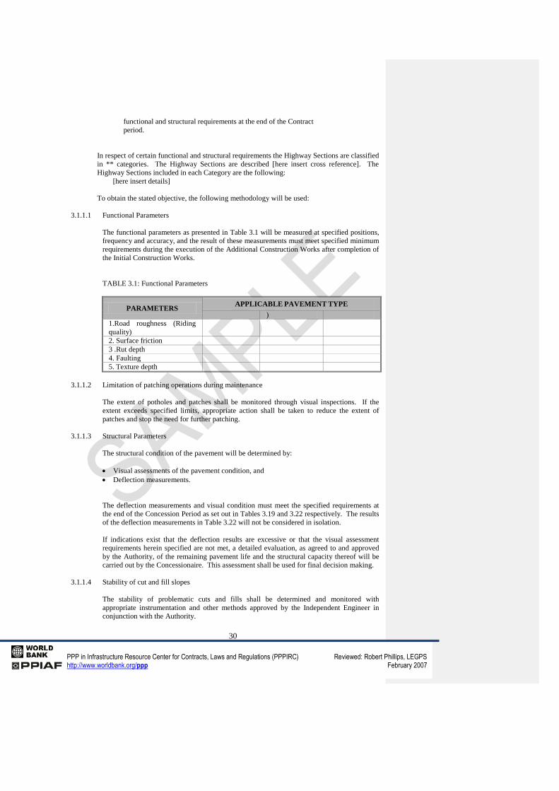
3.1.1.1 Functional Parameters
The functional parameters as presented in Table 3.1 will be measured at specified positions,
frequency and accuracy, and the result of these measurements must meet specified minimum
requirements during the execution of the Additional Construction Works after completion of
the Initial Construction Works.
TABLE 3.1: Functional Parameters
PARAMETERS APPLICABLE PAVEMENT TYPE
)
1.Road roughness (Riding
quality)
2. Surface friction
3 .Rut depth
4. Faulting
5. Texture depth
3.1.1.2 Limitation of patching operations during maintenance
The extent of potholes and patches shall be monitored through visual inspections. If the
extent exceeds specified limits, appropriate action shall be taken to reduce the extent of
patches and stop the need for further patching.
3.1.1.3 Structural Parameters
The structural condition of the pavement will be determined by:
Visual assessments of the pavement condition, and
Deflection measurements.
The deflection measurements and visual condition must meet the specified requirements at
the end of the Concession Period as set out in Tables 3.19 and 3.22 respectively. The results
of the deflection measurements in Table 3.22 will not be considered in isolation.
If indications exist that the deflection results are excessive or that the visual assessment
requirements herein specified are not met, a detailed evaluation, as agreed to and approved
by the Authority, of the remaining pavement life and the structural capacity thereof will be
carried out by the Concessionaire. This assessment shall be used for final decision making.
3.1.1.4 Stability of cut and fill slopes
The stability of problematic cuts and fills shall be determined and monitored with
appropriate instrumentation and other methods approved by the Independent Engineer in
conjunction with the Authority.
31
PPP in Infrastructure Resource Center for Contracts, Laws and Regulations (PPPIRC) Reviewed: Robert Phillips, LEGPS http://www.worldbank.org/ppp February 2007
3.1.1.5 Data capturing and management systems
The frequency of monitoring given in this section must be considered as a minimum
requirement only and the Concessionaire must determine appropriate higher frequencies
according to needs. The data must be processed and captured in a compatible and acceptable
management system agreed with the Authority.
3.1.2 Specifications for Functional Condition
3.1.2.1 Introduction
Assessments of functional conditions shall be undertaken by the Concessionaire or its agent
at prescribed dates and reported in an agreed format.
Before such assessments commence the Concessionaire must notify the Authority and afford
it the opportunity to be represented during the assessments. In addition the Authority
reserves the right to carry out its own assessments.
The systems for the functional conditions are described below:
Specification of the field measurement process:
- Definition of items to be measured.
- Accuracy of measurement.
- Position of measurements.
- Frequency of measurements.
- Measuring equipment.
Specification of data processing and outputs:
- Calculation of functional parameter.
- Statistical processing.
Specification of acceptance criteria:
- Percentile acceptance limits.
- Absolute minimum acceptable values.
3.1.2.2 Road Roughness (Riding Quality)
3.1.2.2.1 Definition
Road roughness is defined as the deviation of a pavement from a true planar surface that
affect vehicle dynamics, riding quality and the dynamic loads exerted on the pavement.
3.1.2.2.2 Measuring equipment
Measurements will be done with an inertial profilometer or similar equipment capable of
producing here insert Class] vertical measurement resolution, and a [ here insert Class ]
longitudinal sampling distance, as defined in [ Here in se code or procedure].
3.1.2.2.3 Calibration and operation
Calibration, validation and operation of the inertial profilometer must be done in accordance
with the manufacturer's requirements, which shall at least meet the requirements of the
Authority.
32
PPP in Infrastructure Resource Center for Contracts, Laws and Regulations (PPPIRC) Reviewed: Robert Phillips, LEGPS http://www.worldbank.org/ppp February 2007
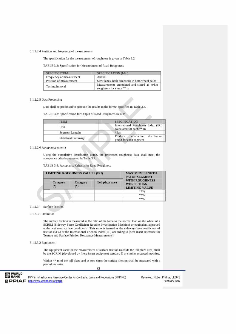
3.1.2.2.4 Position and frequency of measurements
The specification for the measurement of roughness is given in Table 3.2
TABLE 3.2: Specification for Measurement of Road Roughness
SPECIFIC ITEM SPECIFICATION (Min)
Frequency of measurement Annual
Position of measurement Slow lanes, both directions in both wheel paths
Testing interval Measurements cumulated and stored as m/km
roughness for every ** m
3.1.2.2.5 Data Processing
Data shall be processed to produce the results in the format specified in Table 3.3.
TABLE 3.3: Specification for Output of Road Roughness Results
ITEM SPECIFICATION
Unit International Roughness Index (IRI)
calculated for each ** m
Segment Lengths * km
Statistical Summary Produce cumulative distribution
graph for each segment
3.1.2.2.6 Acceptance criteria
Using the cumulative distribution graph, the processed roughness data shall meet the
acceptance criteria presented in Table 3.4.
TABLE 3.4: Acceptance Criteria for Road Roughness
LIMITING ROUGHNESS VALUES (IRI)
MAXIMUM LENGTH
(%) OF SEGMENT
WITH ROUGHNESS
WORSE THAN
LIMITING VALUE
Category
(*)
Category
(*)
Toll plaza area
**%
**%
**%
3.1.2.3 Surface Friction
3.1.2.3.1 Definition
The surface friction is measured as the ratio of the force to the normal load on the wheel of a
SCRIM (Sideway-Force Coefficient Routine Investigation Machine) or equivalent approved
under wet road surface conditions. This ratio is termed as the sideway-force coefficient of
friction (SFC) or the International Friction Index (IFI) according to [here insert reference for
Texture and Surface Friction Resistance Measurements].
3.1.2.3.2 Equipment
The equipment used for the measurement of surface friction (outside the toll plaza area) shall
be the SCRIM (developed by [here insert equipment standard ]) or similar accepted machine.
Within ** m of the toll plaza and at stop signs the surface friction shall be measured with a
pendulum tester.
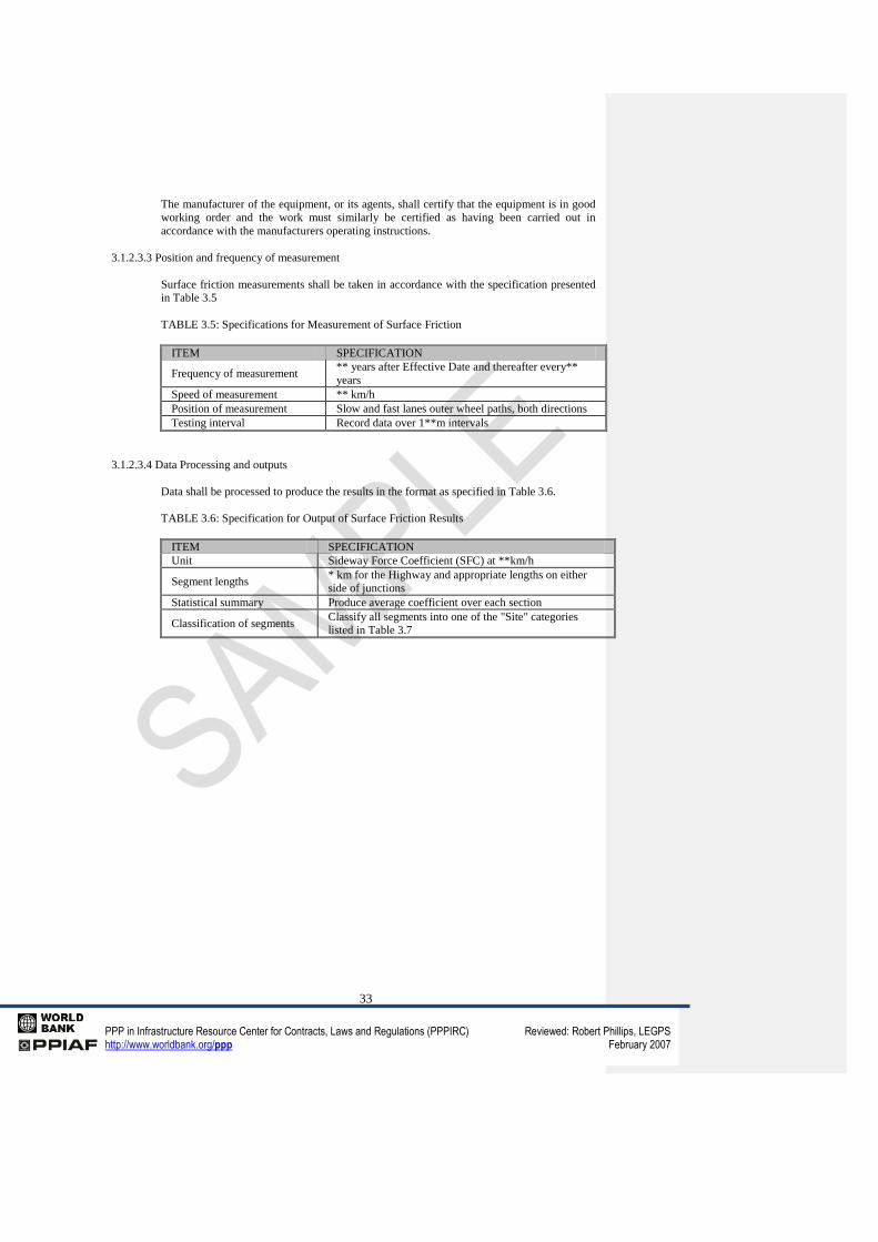
33
PPP in Infrastructure Resource Center for Contracts, Laws and Regulations (PPPIRC) Reviewed: Robert Phillips, LEGPS http://www.worldbank.org/ppp February 2007
The manufacturer of the equipment, or its agents, shall certify that the equipment is in good
working order and the work must similarly be certified as having been carried out in
accordance with the manufacturers operating instructions.
3.1.2.3.3 Position and frequency of measurement
Surface friction measurements shall be taken in accordance with the specification presented
in Table 3.5
TABLE 3.5: Specifications for Measurement of Surface Friction
ITEM SPECIFICATION
Frequency of measurement ** years after Effective Date and thereafter every**
years
Speed of measurement ** km/h
Position of measurement Slow and fast lanes outer wheel paths, both directions
Testing interval Record data over 1**m intervals
3.1.2.3.4 Data Processing and outputs
Data shall be processed to produce the results in the format as specified in Table 3.6.
TABLE 3.6: Specification for Output of Surface Friction Results
ITEM SPECIFICATION
Unit Sideway Force Coefficient (SFC) at **km/h
Segment lengths * km for the Highway and appropriate lengths on either
side of junctions
Statistical summary Produce average coefficient over each section
Classification of segments Classify all segments into one of the "Site" categories
listed in Table 3.7
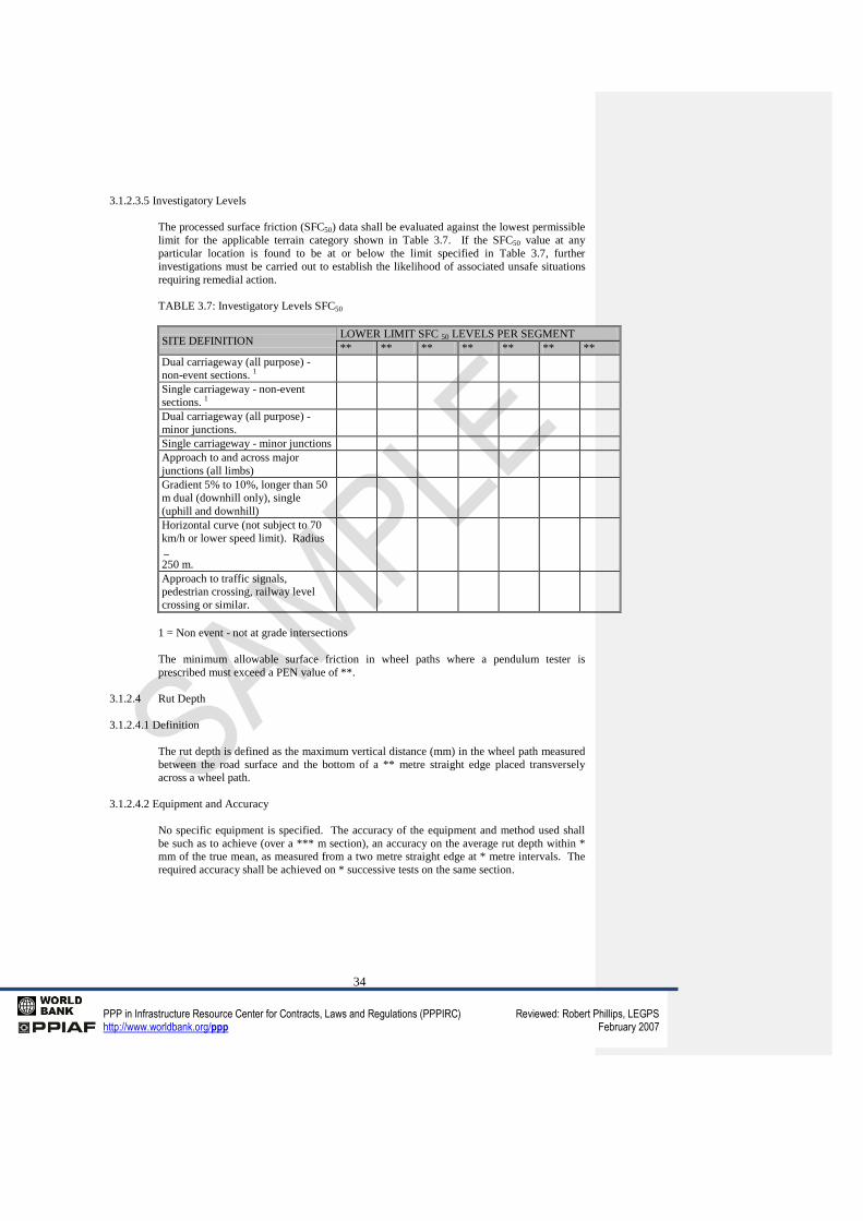
34
PPP in Infrastructure Resource Center for Contracts, Laws and Regulations (PPPIRC) Reviewed: Robert Phillips, LEGPS http://www.worldbank.org/ppp February 2007
3.1.2.3.5 Investigatory Levels
The processed surface friction (SFC50) data shall be evaluated against the lowest permissible
limit for the applicable terrain category shown in Table 3.7. If the SFC50 value at any
particular location is found to be at or below the limit specified in Table 3.7, further
investigations must be carried out to establish the likelihood of associated unsafe situations
requiring remedial action.
TABLE 3.7: Investigatory Levels SFC50
SITE DEFINITION LOWER LIMIT SFC 50 LEVELS PER SEGMENT
** ** ** ** ** ** **
Dual carriageway (all purpose) -
non-event sections. 1
Single carriageway - non-event
sections. 1
Dual carriageway (all purpose) -
minor junctions.
Single carriageway - minor junctions
Approach to and across major
junctions (all limbs)
Gradient 5% to 10%, longer than 50
m dual (downhill only), single
(uphill and downhill)
Horizontal curve (not subject to 70
km/h or lower speed limit). Radius
250 m.
Approach to traffic signals,
pedestrian crossing, railway level
crossing or similar.
1 = Non event - not at grade intersections
The minimum allowable surface friction in wheel paths where a pendulum tester is
prescribed must exceed a PEN value of **.
3.1.2.4 Rut Depth
3.1.2.4.1 Definition
The rut depth is defined as the maximum vertical distance (mm) in the wheel path measured
between the road surface and the bottom of a ** metre straight edge placed transversely
across a wheel path.
3.1.2.4.2 Equipment and Accuracy
No specific equipment is specified. The accuracy of the equipment and method used shall
be such as to achieve (over a *** m section), an accuracy on the average rut depth within *
mm of the true mean, as measured from a two metre straight edge at * metre intervals. The
required accuracy shall be achieved on * successive tests on the same section.
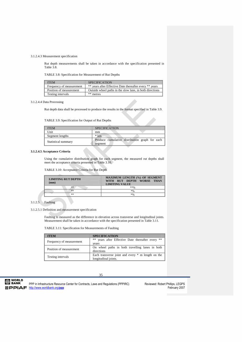
35
PPP in Infrastructure Resource Center for Contracts, Laws and Regulations (PPPIRC) Reviewed: Robert Phillips, LEGPS http://www.worldbank.org/ppp February 2007
3.1.2.4.3 Measurement specification
Rut depth measurements shall be taken in accordance with the specification presented in
Table 3.8.
TABLE 3.8: Specification for Measurement of Rut Depths
ITEM SPECIFICATION
Frequency of measurement ** years after Effective Date thereafter every ** years
Position of measurement Outside wheel paths in the slow lane, in both directions
Testing intervals ** metres
3.1.2.4.4 Data Processing
Rut depth data shall be processed to produce the results in the format specified in Table 3.9.
TABLE 3.9: Specification for Output of Rut Depths
ITEM SPECIFICATION
Unit mm
Segment lengths * km
Statistical summary Produce cumulative distribution graph for each
segment
3.1.2.4.5 Acceptance Criteria
Using the cumulative distribution graph for each segment, the measured rut depths shall
meet the acceptance criteria presented in Table 3.10.
TABLE 3.10: Acceptance Criteria for Rut Depth
LIMITING RUT DEPTH
(mm)
MAXIMUM LENGTH (%) OF SEGMENT
WITH RUT DEPTH WORSE THAN
LIMITING VALUE
** **%
** *%
** *%
3.1.2.5 Faulting
3.1.2.5.1 Definition and measurement specification
Faulting is measured as the difference in elevation across transverse and longitudinal joints.
Measurement shall be taken in accordance with the specification presented in Table 3.11.
TABLE 3.11: Specification for Measurements of Faulting
ITEM SPECIFICATION
Frequency of measurement ** years after Effective Date thereafter every **
years
Position of measurement On wheel paths in both travelling lanes in both
directions
Testing intervals Each transverse joint and every * m length on the
longitudinal joints.
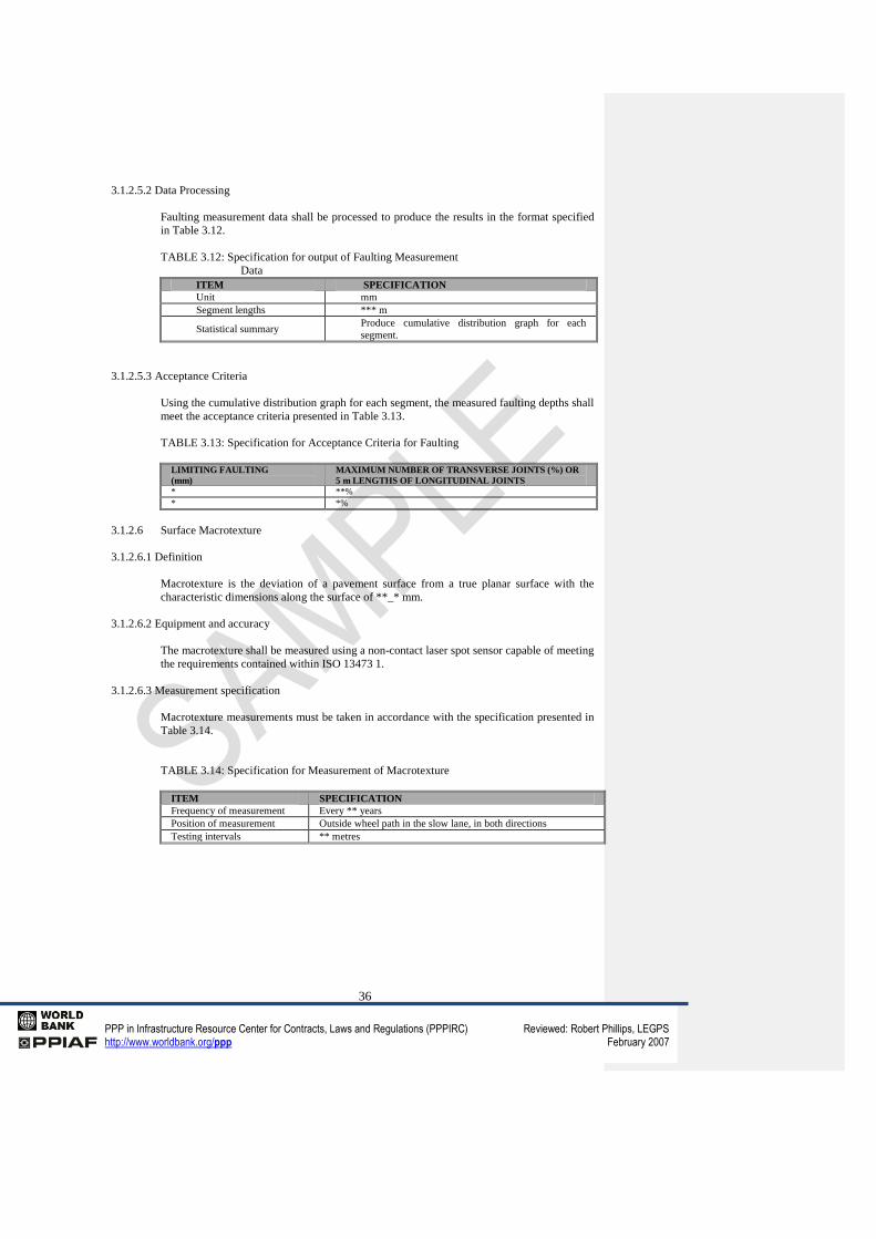
36
PPP in Infrastructure Resource Center for Contracts, Laws and Regulations (PPPIRC) Reviewed: Robert Phillips, LEGPS http://www.worldbank.org/ppp February 2007
3.1.2.5.2 Data Processing
Faulting measurement data shall be processed to produce the results in the format specified
in Table 3.12.
TABLE 3.12: Specification for output of Faulting Measurement
Data
ITEM SPECIFICATION
Unit mm
Segment lengths *** m
Statistical summary Produce cumulative distribution graph for each
segment.
3.1.2.5.3 Acceptance Criteria
Using the cumulative distribution graph for each segment, the measured faulting depths shall
meet the acceptance criteria presented in Table 3.13.
TABLE 3.13: Specification for Acceptance Criteria for Faulting
LIMITING FAULTING
(mm)
MAXIMUM NUMBER OF TRANSVERSE JOINTS (%) OR
5 m LENGTHS OF LONGITUDINAL JOINTS
* **%
* *%
3.1.2.6 Surface Macrotexture
3.1.2.6.1 Definition
Macrotexture is the deviation of a pavement surface from a true planar surface with the
characteristic dimensions along the surface of **_* mm.
3.1.2.6.2 Equipment and accuracy
The macrotexture shall be measured using a non-contact laser spot sensor capable of meeting
the requirements contained within ISO 13473 1.
3.1.2.6.3 Measurement specification
Macrotexture measurements must be taken in accordance with the specification presented in
Table 3.14.
TABLE 3.14: Specification for Measurement of Macrotexture
ITEM SPECIFICATION
Frequency of measurement Every ** years
Position of measurement Outside wheel path in the slow lane, in both directions
Testing intervals ** metres
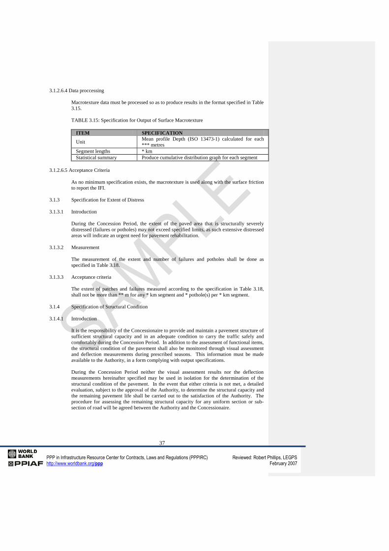
37
PPP in Infrastructure Resource Center for Contracts, Laws and Regulations (PPPIRC) Reviewed: Robert Phillips, LEGPS http://www.worldbank.org/ppp February 2007
3.1.2.6.4 Data proccessing
Macrotexture data must be processed so as to produce results in the format specified in Table
3.15.
TABLE 3.15: Specification for Output of Surface Macrotexture
ITEM SPECIFICATION
Unit Mean profile Depth (ISO 13473-1) calculated for each
*** metres
Segment lengths * km
Statistical summary Produce cumulative distribution graph for each segment
3.1.2.6.5 Acceptance Criteria
As no minimum specification exists, the macrotexture is used along with the surface friction
to report the IFI.
3.1.3 Specification for Extent of Distress
3.1.3.1 Introduction
During the Concession Period, the extent of the paved area that is structurally severely
distressed (failures or potholes) may not exceed specified limits, as such extensive distressed
areas will indicate an urgent need for pavement rehabilitation.
3.1.3.2 Measurement
The measurement of the extent and number of failures and potholes shall be done as
specified in Table 3.18.
3.1.3.3 Acceptance criteria
The extent of patches and failures measured according to the specification in Table 3.18,
shall not be more than ** m for any * km segment and * pothole(s) per * km segment.
3.1.4 Specification of Structural Condition
3.1.4.1 Introduction
It is the responsibility of the Concessionaire to provide and maintain a pavement structure of
sufficient structural capacity and in an adequate condition to carry the traffic safely and
comfortably during the Concession Period. In addition to the assessment of functional items,
the structural condition of the pavement shall also be monitored through visual assessment
and deflection measurements during prescribed seasons. This information must be made
available to the Authority, in a form complying with output specifications.
During the Concession Period neither the visual assessment results nor the deflection
measurements hereinafter specified may be used in isolation for the determination of the
structural condition of the pavement. In the event that either criteria is not met, a detailed
evaluation, subject to the approval of the Authority, to determine the structural capacity and
the remaining pavement life shall be carried out to the satisfaction of the Authority. The
procedure for assessing the remaining structural capacity for any uniform section or sub-
section of road will be agreed between the Authority and the Concessionaire.
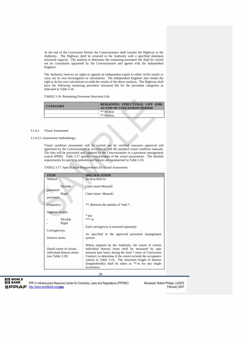
38
PPP in Infrastructure Resource Center for Contracts, Laws and Regulations (PPPIRC) Reviewed: Robert Phillips, LEGPS http://www.worldbank.org/ppp February 2007
At the end of the Concession Period, the Concessionaire shall transfer the Highway to the
Authority. The Highway shall be returned to the Authority with a specified minimum
structural capacity. The analysis to determine the remaining pavement life shall be carried
out by consultants appointed by the Concessionaire and agreed with the Independent
Engineer.
The Authority reserves its rights to appoint an independent expert to either verify results or
carry out its own investigation or calculations. The Independent Engineer also retains the
right to do his own calculations to audit the results of the above analysis. The Highway shall
have the following remaining pavement structural life for the pavement categories as
indicated in Table 3.16.
TABLE 3.16: Remaining Pavement Structural Life
CATEGORY REMAINING STRUCTURAL LIFE (E80)
AT END OF CONCESSION PERIOD
** Million
** Million
3.1.4.2 Visual Assessment
3.1.4.2.1 Assessment methodology:
Visual condition assessment will be carried out by certified assessors approved and
appointed by the Concessionaire in accordance with the standard visual condition manuals.
The data will be processed and captured by the Concessionaire in a pavement management
system (PMS). Table 3.17 specifies requirements of the visual assessments. The detailed
requirements for patching potholes and failures are summarised in Table 3.18.
TABLE 3.17: Specification Requirements for Visual Assessment
ITEM SPECIFICATION
Method:
- Flexible
pavement
- Rigid
pavement
Frequency:
Segment length:
- Flexible
- Rigid
Carriageways:
Distress items:
Detail extent of certain
individual distress items:
(see Table 3.19)
As described in:
[ here insert Manual]
[ here insert Manual}
**: Between the months of *and *.
* km
*** m
Each carriageway is assessed separately
As specified in the approved pavement management
system
Where required by the Authority, the extent of certain
individual distress items shall be measured by tape
measure (per lane), during the final * years of Concession
Contract, to determine if the extent exceeds the acceptance
criteria in Table 3.19. The minimum length of distress
(longitudinally) shall be taken as ** m for any single
occurrence.

39
PPP in Infrastructure Resource Center for Contracts, Laws and Regulations (PPPIRC) Reviewed: Robert Phillips, LEGPS http://www.worldbank.org/ppp February 2007
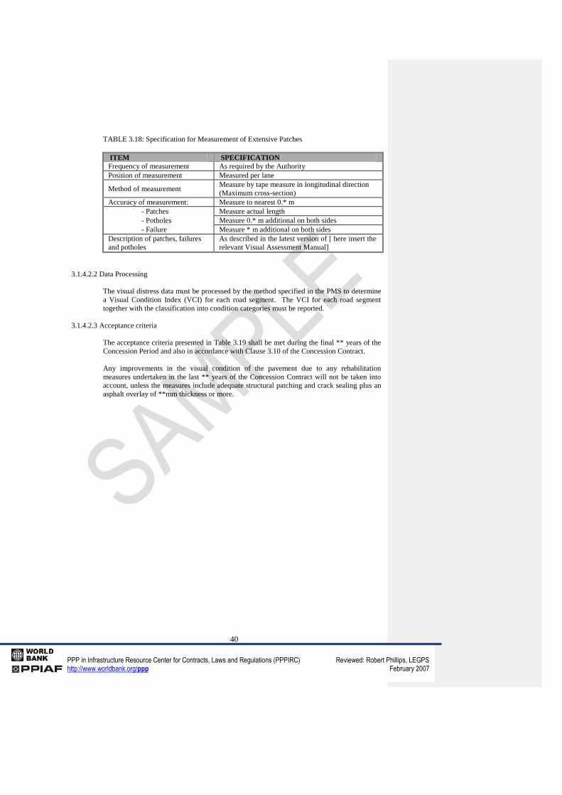
40
PPP in Infrastructure Resource Center for Contracts, Laws and Regulations (PPPIRC) Reviewed: Robert Phillips, LEGPS http://www.worldbank.org/ppp February 2007
TABLE 3.18: Specification for Measurement of Extensive Patches
ITEM SPECIFICATION
Frequency of measurement As required by the Authority
Position of measurement Measured per lane
Method of measurement Measure by tape measure in longitudinal direction
(Maximum cross-section)
Accuracy of measurement: Measure to nearest 0.* m
- Patches Measure actual length
- Potholes Measure 0.* m additional on both sides
- Failure Measure * m additional on both sides
Description of patches, failures
and potholes
As described in the latest version of [ here insert the
relevant Visual Assessment Manual]
3.1.4.2.2 Data Processing
The visual distress data must be processed by the method specified in the PMS to determine
a Visual Condition Index (VCI) for each road segment. The VCI for each road segment
together with the classification into condition categories must be reported.
3.1.4.2.3 Acceptance criteria
The acceptance criteria presented in Table 3.19 shall be met during the final ** years of the
Concession Period and also in accordance with Clause 3.10 of the Concession Contract.
Any improvements in the visual condition of the pavement due to any rehabilitation
measures undertaken in the last ** years of the Concession Contract will not be taken into
account, unless the measures include adequate structural patching and crack sealing plus an
asphalt overlay of **mm thickness or more.
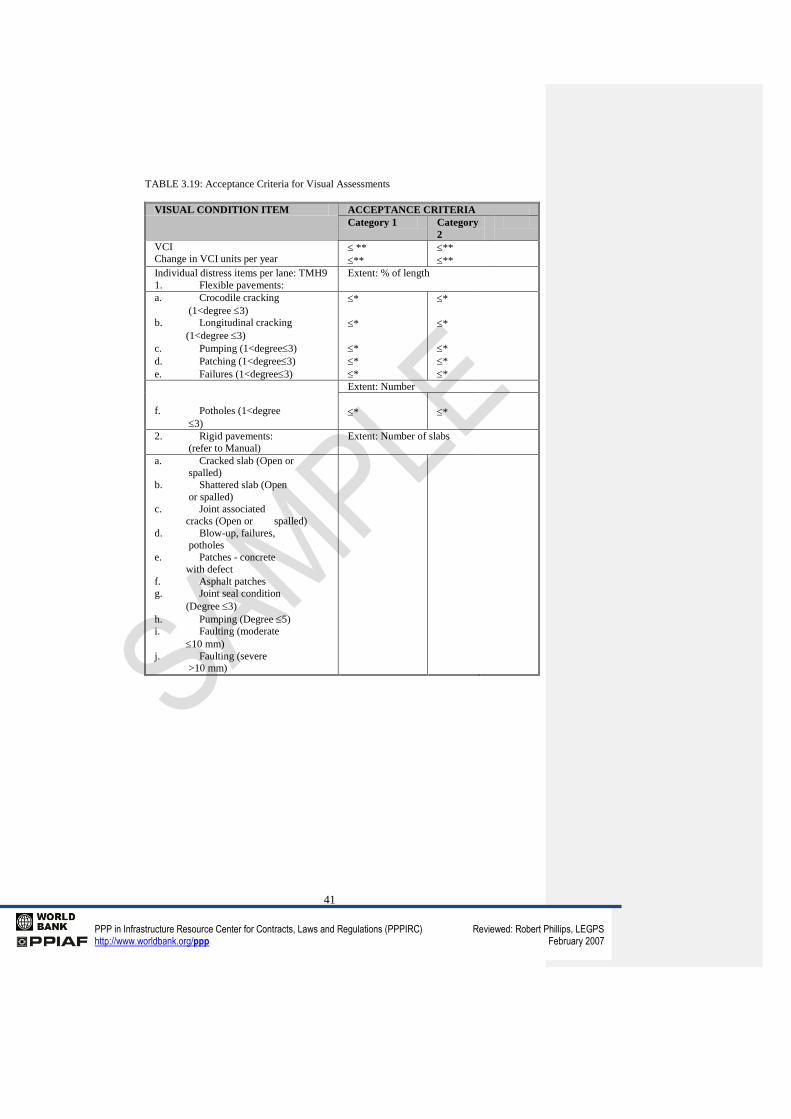
41
PPP in Infrastructure Resource Center for Contracts, Laws and Regulations (PPPIRC) Reviewed: Robert Phillips, LEGPS http://www.worldbank.org/ppp February 2007
TABLE 3.19: Acceptance Criteria for Visual Assessments
VISUAL CONDITION ITEM ACCEPTANCE CRITERIA
Category 1 Category
2
VCI
Change in VCI units per year **
**
**
**
Individual distress items per lane: TMH9
1. Flexible pavements:
Extent: % of length
a. Crocodile cracking
(1<degree 3)
b. Longitudinal cracking
(1<degree 3)
c. Pumping (1<degree3)
d. Patching (1<degree3)
e. Failures (1<degree3)
*
*
*
*
*
*
*
*
*
*
f. Potholes (1<degree
3)
Extent: Number
*
*
2. Rigid pavements:
(refer to Manual)
Extent: Number of slabs
a. Cracked slab (Open or
spalled)
b. Shattered slab (Open
or spalled)
c. Joint associated
cracks (Open or spalled)
d. Blow-up, failures,
potholes
e. Patches - concrete
with defect
f. Asphalt patches
g. Joint seal condition
(Degree 3)
h. Pumping (Degree 5)
i. Faulting (moderate
10 mm)
j. Faulting (severe
>10 mm)
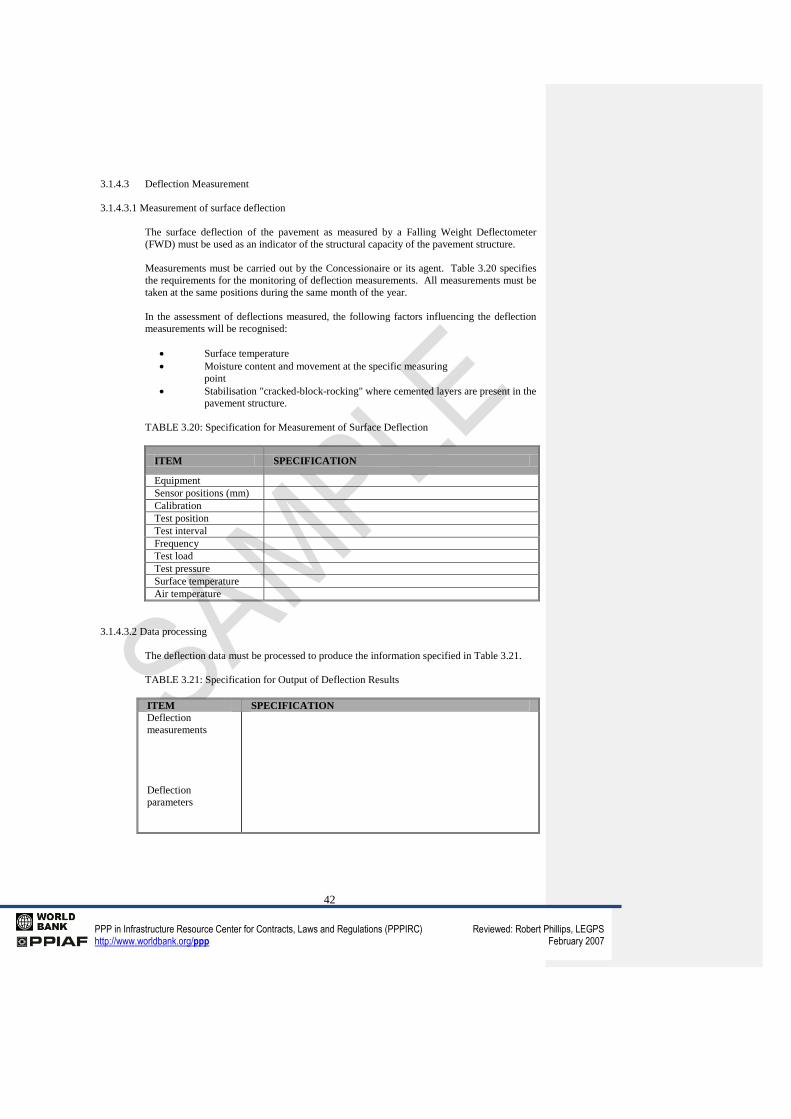
42
PPP in Infrastructure Resource Center for Contracts, Laws and Regulations (PPPIRC) Reviewed: Robert Phillips, LEGPS http://www.worldbank.org/ppp February 2007
3.1.4.3 Deflection Measurement
3.1.4.3.1 Measurement of surface deflection
The surface deflection of the pavement as measured by a Falling Weight Deflectometer
(FWD) must be used as an indicator of the structural capacity of the pavement structure.
Measurements must be carried out by the Concessionaire or its agent. Table 3.20 specifies
the requirements for the monitoring of deflection measurements. All measurements must be
taken at the same positions during the same month of the year.
In the assessment of deflections measured, the following factors influencing the deflection
measurements will be recognised:
Surface temperature
Moisture content and movement at the specific measuring
point
Stabilisation "cracked-block-rocking" where cemented layers are present in the
pavement structure.
TABLE 3.20: Specification for Measurement of Surface Deflection
ITEM SPECIFICATION
Equipment
Sensor positions (mm)
Calibration
Test position
Test interval
Frequency
Test load
Test pressure
Surface temperature
Air temperature
3.1.4.3.2 Data processing
The deflection data must be processed to produce the information specified in Table 3.21.
TABLE 3.21: Specification for Output of Deflection Results
ITEM SPECIFICATION
Deflection
measurements
Deflection
parameters
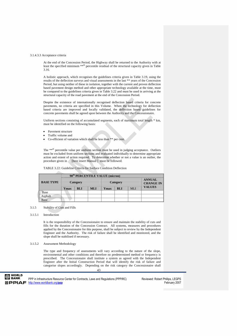
43
PPP in Infrastructure Resource Center for Contracts, Laws and Regulations (PPPIRC) Reviewed: Robert Phillips, LEGPS http://www.worldbank.org/ppp February 2007
3.1.4.3.3 Acceptance criteria
At the end of the Concession Period, the Highway shall be returned to the Authority with at
least the specified minimum **th
percentile residual of the structural capacity given in Table
3.16.
A holistic approach, which recognises the guidelines criteria given in Table 3.19, using the
results of the deflection surveys and visual assessments in the last ** years of the Concession
Period, but using neither of these in isolation, together with the current and proven deflection
based pavement design method and other appropriate technology available at the time, must
be compared to the guidelines criteria given in Table 3.22 and must be used in arriving at the
structural capacity of the road pavement at the end of the Concession Period.
Despite the existence of internationally recognised deflection based criteria for concrete
pavements, no criteria are specified in this Volume. When the technology for deflection
based criteria are improved and locally validated, the deflection based guidelines for
concrete pavements shall be agreed upon between the Authority and the Concessionaire.
Uniform sections consisting of accumulated segments, each of maximum total length * km,
must be identified on the following basis:
Pavement structure
Traffic volume and
Co-efficient of variation which shall be less than ** per cent.
The **th
percentile value per uniform section must be used in judging acceptance. Outliers
must be excluded from uniform sections and evaluated individually to determine appropriate
action and extent of action required. To determine whether or not a value is an outlier, the
procedure given in [here insert Manual ] must be followed.
TABLE 3.22: Guideline Criteria for Surface Condition Deflection
BASE TYPE
90th
PERCENTILE VALUE (micron)
Category Category ANNUAL
CHANGE IN
VALUES Ymax BLI MLI Ymax BLI MLI
Base
Asphalt
Base
3.1.5 Stability of Cuts and Fills
3.1.5.1 Introduction
It is the responsibility of the Concessionaire to ensure and maintain the stability of cuts and
fills for the duration of the Concession Contract. All systems, measures and procedures
applied by the Concessionaire for this purpose, shall be subject to review by the Independent
Engineer and the Authority. The risk of failure shall be identified and monitored, and the
slope shall be stabilised if necessary.
3.1.5.2 Assessment Methodology
The type and frequency of assessments will vary according to the nature of the slope,
environmental and other conditions and therefore no predetermined method or frequency is
prescribed. The Concessionaire shall institute a system as agreed with the Independent
Engineer after the Initial Construction Period that will identify the risk of failure and
categorise slopes accordingly. Depending on the risk category the Concessionaire shall
44
PPP in Infrastructure Resource Center for Contracts, Laws and Regulations (PPPIRC) Reviewed: Robert Phillips, LEGPS http://www.worldbank.org/ppp February 2007
institute appropriate monitoring procedures. The monitoring procedures shall, amongst
other things, include the recording of movements, crack development, seepage, slides, slips,
rockfall etc.
All geotechnical measures used for stabilising fills and slopes like core drains, anchors,
dowels, pins, subsurface and other drains, retaining walls etc. shall also be monitored
regularly for effectiveness.
3.1.5.3 Acceptance criteria
The output from the regular assessments shall be analysed by a professional geotechnical
engineer and compared with acceptable criteria for the type and nature of the slopes. During
this process stabilisation measures shall be identified and, where necessary, implemented to
safeguard motorists and the integrity of the facility.
3.2 Traffic
3.2.1 General
The Concessionaire shall install and maintain a system of traffic monitoring stations as part
of a traffic management system, in order to monitor traffic movements and loading along,
across and entering and leaving the Highway.
The counts shall include all details required to calculate the Level of Service (LOS) at all
segments along the road as well as at interchanges and at intersections as and when required.
Where Construction Works necessitate the removal or destruction of a counting station, it
must be reinstated as soon as practically possible. Whenever damage is caused to one of the
Authority's Comprehensive Traffic Observations (CTO) counting stations by the
Concessionaire's Activities, the Concessionaire must reimburse the Authority for reinstating
such counting station.
3.2.2 Traffic Monitoring
To evaluate traffic flows and traffic loading, monitoring is required on an ongoing basis.
The Concessionaire shall provide the Authority with traffic data annually and when required.
The traffic counting programme shall comply with the following requirements:
a. Counting stations shall be installed by the Concessionaire and shall be made
operational and be maintained. Where construction or rehabilitation work
necessitates the removal or destruction of a station, this station shall be replaced on
completion of the construction/rehabilitation work, or alternatively, on agreement
between the Authority and the Concessionaire, relocated to another location.
b. A traffic counting plan will be drawn up and discussed on an annual basis.
c. In addition to the above, counts available from the toll plazas shall be utilised for
traffic assessments.
d. It is a requirement that all the counting stations are permanent. The Authority
requires counting stations to be fully functional for an average of at least **% of the
time calculated on a yearly basis.
e. Traffic information required for a specific section where no counter or counting
station has been installed will be derived from traffic study information if suitable.
Should it however be required, short term machine counting will be arranged to
substantiate traffic study figures and or other permanent counting stations.
f. { Does the Authority currently have an existing CTO station on the Highway?] The
Concessionaire must, however, install, operate and maintain a permanent counting
station in accordance with the agreed traffic counting plan. A suitable location for
this would be at the Toll Plaza.
g. At all significant interchanges and intersections automatic traffic counts of ** week
duration annually shall be undertaken. These counts shall be supplemented by a **
day (** hr) count to individually account for all turning movements at the
45
PPP in Infrastructure Resource Center for Contracts, Laws and Regulations (PPPIRC) Reviewed: Robert Phillips, LEGPS http://www.worldbank.org/ppp February 2007
intersections. The specific week for conducting the **week intersection counts shall
be determined from the output of the permanent stations outside normal peak hours
and subject to the approval of the Authority. Interchange ramp terminals must be
dealt with in the same way.
3.2.3 Traffic Analysis Strategy
a. For the Highway
Uniform segments of the Highway must be identified in terms of cross-sections,
horizontal and vertical design standards, access control, and traffic patterns. These
uniform segments must be recorded on a distance-flow rate diagram. Traffic patterns
can be derived from permanent and other traffic counting stations.
Each uniform segment of Highway must be analysed for specific road characteristics
as indicated in the latest Highway Capacity Manual (HCM). The variables used in
the analysis must be in accordance with good industry practice.
The following information must be made available in advance of every meeting
pertaining to the establishment of an Additional Construction Works Programme:
i. a distance-flow rate diagram for "LOS 'D' " of the Highway, indicating
capacity demand and capacity provided;
ii. reporting on and re-assessment of traffic volumes;
iii level of service of each uniform segment of Highway;
iv the estimated remaining period for each uniform segment of Highway before
upgrading will be required; and
v. safety report and remedial measures necessary to ensure safe operations.
b. For intersections
Data from detailed intersection traffic counts and other counts shall be subjected to
detailed capacity analysis of all turning and through movements using the latest
suitable computer software. Such an analysis must be conducted for each intersection
annually.
A report of the results of each analysis must be prepared and must contain:
i. the prevailing levels of service, average delays, and volume to capacity ratio
experienced for each movement at the intersection concerned;
ii. the expected capacity lifespan of the intersection or parts thereof in terms of
the traffic capacity requirements specified; and
iii recommendations for the upgrading of the intersection or parts thereof to fulfil
the capacity criteria.
c. For the [relevant] Interchange
Data from detailed traffic counts at interchange ramp terminals and other available
traffic counts must be used for conducting detailed analyses of all turning movements
at ramp terminals, as well as merging and diverging movements at on- and off-ramps.
Such an analysis must be conducted for each Interchange annually. A report must be
prepared of the results of the analysis and must contain;
i. the prevailing levels of service, average delays and volume to capacity (V/C)
ratios experienced for each movement at the interchange ramp terminals;
ii. levels of service for merging and diverging movements for the on- and off-
ramps;
iii the expected capacity lifespan of the interchange and all parts thereof in terms
of the traffic capacity requirements specified; and
46
PPP in Infrastructure Resource Center for Contracts, Laws and Regulations (PPPIRC) Reviewed: Robert Phillips, LEGPS http://www.worldbank.org/ppp February 2007
iv recommendations for upgrading the interchange or parts thereof to fulfil the
required capacity criteria.
3.2.4 Highway Capacity
a. Capacity criteria for the Highway
Subject to the requirements of the Concession Contract the Concessionaire shall
ensure that a Level of Service D (LOSD), [here insert relevant reference manual] will
be achieved along the road during all hours of the year except the ** hours with the
highest traffic volumes. In addition, Level of Service D (LOSD) shall be achievable
during the peak hour.
The peak hour for urban road Level of Service assessment shall be taken as the
average weekday peak hour, where “average weekday peak hour” means the average
peak hour traffic volume for ** consecutive weekdays (excluding Saturdays and
Sundays) outside holiday periods. For dual carriageway roads in urban areas, the
average weekday peak hour as well as the peak hour assessment shall be calculated
separately for each carriageway.
If this cannot be achieved, capacity improvements shall be introduced by means of
industry accepted traffic management procedures, additional lanes, climbing lanes,
passing lanes or other suitable acceptable means as agreed with the Authority. The
maximum cross section of freeways in an urban environment shall be ** lanes per
direction.
Where the level of service on an ** lane freeway in an urban environment exceeds
(LOSD) during the average weekday peak hour and will not be addressed by the
construction of other portions of the road network in the area, the Concessionaire
undertakes to introduce management systems to remedy the situation such as:
Access Management to limit the demand on the specific section of Highway
involved
Differential tolling rates to achieve a more balanced distribution of traffic and
thus limit the demand in the peak hours.
Any other systems approved by the Authority.
The Concessionaire also undertakes to take due cognisance of blockages of cross
roads and to enter into discussions with the Relevant Authorities on road planning
issues with the objective of resolving the situation. In urban sections along the road,
intersection capacity analysis as per prescribed specifications shall be used to carry
out level of service calculations. The specified level of service to be maintained at
intersections is as specified in sub-paragraph (b) below.
b. Capacity criteria for intersections
i. For urban intersections
Capacity related requirements for urban intersections must be judged in terms
of the performance (measure of effectiveness) of the intersections during
average weekday morning and afternoon peak hours and the Saturday peak
hour. The measure of effectiveness is the average stopped delay and/or volume
to capacity ratio per lane group for a signalised intersection and average total
delay for a priority controlled intersection. The level of service at which a lane
group operates is based on the delay per vehicle. Intersections must be
upgraded when the level of service of any particular lane group is worse than
LOSD and/or the average volume to capacity ratio exceeds ** for a signalised
intersection. In addition, for right turning movements at signalised
intersections, the capacity requirements, namely LOSD and volume to capacity
Comment [ID11]: [note-week-end depends upon cultural background and will be depend upon location of the Project].
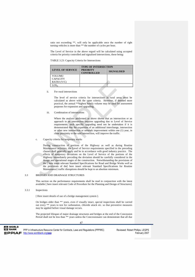
47
PPP in Infrastructure Resource Center for Contracts, Laws and Regulations (PPPIRC) Reviewed: Robert Phillips, LEGPS http://www.worldbank.org/ppp February 2007
ratio not exceeding **, will only be applicable once the number of right
turning vehicles is more than ** the number of cycles per hour.
The Level of Service in the above regard will be calculated using accepted
criteria for priority controlled and signalised intersections, these being:
TABLE 3.23: Capacity Criteria for Intersections
LEVEL OF SERVICE
TYPE OF INTERSECTION
PRIORITY
CONTROLLED SIGNALISED
VOLUME/
CAPACITY
RATIO (V/C)
LOSD
ii. For rural intersections
The level of service criteria for intersections in rural areas must be
calculated as above with the same criteria. However, if deemed more
practical, the annual **highest hourly volume may be used for assessment
purposes for expansion and upgrading.
iii. Combination of intersections
Where the analysis performed as above shows that an intersection or an
approach to an intersection requires upgrading due to Level of Service
requirements, such specific upgrading need not be undertaken if it is
demonstrated that the expansion of an additional interchange, intersection
or other new intersection or network improvement within one (1) year, in
close proximity to the said intersection, will improve the traffic.
c. Capacity criteria for temporary works
During construction of portions of the Highway as well as during Routine
Maintenance activities, the Level of Service requirements specified in the preceding
clauses shall generally apply and be in accordance with good industry practice. The
effects of temporary deviations on the Level of Service of the portions of the
Highway immediately preceding the deviation should be carefully considered in the
design and operational stages of the construction. Notwithstanding the provisions of
the [ here insert relevant Standard Specifications for Road and Bridge Works well as
the provisions of the[ here insert relevant Standard Specifications for Routine
Maintenance} traffic disruptions should be kept to an absolute minimum.
3.3 BRIDGES AND DRAINAGE STRUCTURES
This section on the performance requirements shall be read in conjunction with the latest
available [ here insert relevant Code of Procedure for the Planning and Design of Structures].
3.3.1 Inspections
[ Here insert details of use of a bridge management system ].
On bridges older than ** years, even if visually intact, special inspections shall be carried
out every ** years to test for carbonation, chloride attack etc. so that preventive measures
may be applied before visual damage occurs.
The projected lifespan of major drainage structures and bridges at the end of the Concession
Period shall not be less than ** years unless the Concessionaire can demonstrate that all due
48
PPP in Infrastructure Resource Center for Contracts, Laws and Regulations (PPPIRC) Reviewed: Robert Phillips, LEGPS http://www.worldbank.org/ppp February 2007
care had been taken to limit the penetration of carbonation or chloride salts or other chemical
activities that lead to the corrosion of the reinforcement steel.
The project lifetime calculations, and the tests required for these, shall be carried out by an
authority mutually agreed to by the Authority and the Concessionaire.
3.3.2 Ratings of Bridge Elements
The bridge management system to be adopted by the Concessionaire ( the Bridge
Management System} shall be is based on [ here insert relevant Defect, Extent and
Relevancy (DER) system ]. For a bridge to be considered acceptable the rating of any defect
of all its elements shall not be more than *. Any element that has a relevancy or urgency
rating of * shall be regarded as Critical or Urgent and shall be dealt with as soon as possible.
3.3.3 Concrete Defects
Any defects falling below an acceptable rating shall be monitored and shall be repaired
before the defect becomes so serious as to be hazardous. The Concessionaire shall use [ here
insert relevant code or procedure for the Rehabilitation and Repair of Concrete Bridges ] as a
guide for the repair of all concrete elements.
3.3.4 Accidental Damage to Structures
The structure shall immediately be made safe and repairs effected to restore the structure to
its original condition.
3.3.5 Expansion Joints
a. General
All expansion joints shall be tested to ensure that they are watertight at the time of
installation and during its service life. In addition the maximum gap between
concrete nosings, or metal cross beams in the case of multi-element joints, shall be
**mm under the worst minimum temperature conditions. For new bridge structures
under **m in length jointless bridges shall be preferred (if possible) to minimize
maintenance in the future.
The bridge inspections shall be carried out at maximum ** year intervals in
compliance with the Bridge Management System and which shall include watertight
tests as described below.
b. Water tightness test
On completion of the joint or component installation, the Concessionaire shall
perform a water tightness test of the joint. The test shall consist of ponding water to a
depth of at least **mm above the highest point of the joint constructed under the
particular phase of work (i.e. half width). The ponding shall be maintained for
**hour(s) and if no evidence of leakage is detected, the joint shall be accepted as
being of watertight construction.
If the joint is found to be leaking, the Concessionaire shall remedy the situation and
repeat tests on the affected section of joint. The testing shall be carried out
immediately on completion of the section of the joint to take advantage of the
accommodation of traffic arrangements in existence at the time.
3.3.6 Rehabilitation
The rehabilitation of a bridge shall include the following:
a. The repair of existing balustrades/parapets.
49
PPP in Infrastructure Resource Center for Contracts, Laws and Regulations (PPPIRC) Reviewed: Robert Phillips, LEGPS http://www.worldbank.org/ppp February 2007
b. The refurbishment / replacement of bearings.
c. The replacement of neoprene seals in gland type joints, the removal of failed pressfit
seals which are replaced by a silicon sealant if the concrete nosings are in a sound
condition or the total replacement of an expansion joint.
d. The repair of concrete spalling, crack repair by injection/ sealing, corrosion repair of
reinforcement, replacement/ repair/painting of guardrails.
e. Reinstatement of embankment erosion/scour protection.
f. Repair of road approaches and bridge surfacing.
Upgrading
[ here set out regime if one is to be created]
3.4 Toll Plazas
The average service time (queuing and processing) at the toll plazas shall not be longer than
** seconds. When ** random observations are made during any ** minute period the
maximum number of vehicles queuing shall not exceed more than once the value of **
multiplied by the number of open lanes (see requirement in subclause 2.5.3.)
3.5 Routine Maintenance
3.5.1 Scope
The scope of Routine Maintenance shall be as specified in Clause 2.7, and Schedule 1 and
in the relevant standard specifications of the [ here insert relevant code or procedure].
3.5.2 Performance Inspection
The Independence Engineer may, at any time, and at any frequency determined by the
Independent Engineer inspect any Test Section (or any number of Test Sections) to audit
compliance of a relevant Routine Maintenance Section with the Acceptance Criteria.
For the purpose of this clause 3.5:
“Acceptance Criteria” means the acceptance criteria of the Highway specified in Schedule 1.
“Non-Performance Points” means a point or points given to the urgency rating / weighing
for Routine Maintenance features listed in Schedule 1.
“Test Section” mains any continuous or cumulative** km portion of a Routine Maintenance
Section (as randomly determined by the Independent Engineer) as measured along the
centreline of the Highway.
“Routine Maintenance Section” means continuous ** km sections of
the Highway as agreed by the parties prior to the Effective Date.
3.5.3 First Non-Conformance Certificate
3.5.3.1 If, on an inspection of any Test Sections, the Independent Engineer determines that any
Acceptance Criteria is not satisfied then the Independent Engineer shall notify the
Concessionaire of the non-compliance.
3.5.3.2 Within * Business Days of the Independent Engineer having delivered to the Concessionaire
the notification referred to in clause 3.5.3.1 above, the Concessionaire may deliver to the
50
PPP in Infrastructure Resource Center for Contracts, Laws and Regulations (PPPIRC) Reviewed: Robert Phillips, LEGPS http://www.worldbank.org/ppp February 2007
Independent Engineer proof that the non-conformance with the Acceptance Criteria has not
continued for a period longer than the relevant Correction Period for such non-conformance
as specified in Schedule 1 (the “Correction Period”).
3.5.3.3 If the Concessionaire has not demonstrated to the reasonable satisfaction of the Independent
Engineer within the period specified in clause 3.5.3.2 that the non-conformance of any
Routine Road Maintenance feature in terms of the Acceptance Criteria has not continued for
a period longer than the Correction Period, the Concessionaire shall accrue Non-
conformance Points for such non-conforming features (as specified in Schedule 1) which
exceeded their respective Correction Periods.
3.5.3.4 If 5 or more Non-Performance Points have accrued in respect of a Test Section (as
determined by the Independent Engineer)
a) the Independent Engineer shall issue a notice to the Concessionaire (the “First Non-
Conformance Notice”) setting out the aggregate of Non-Performance Points for the
relevant Test Section in a particular ** km Routine Maintenance Section as
determined by the Independent Engineer, and
b) the Concessionaire shall pay to the Authority a penalty calculated pursuant to clause
3.5.3.5 in respect of the relevant Routine Maintenance Section.
3.5.3.5 The penalty for non-compliance with the Acceptance Criteria specified in a First Non-
Conformance Notice shall be equal to an amount calculated as follows :
P = Y (Gross Daily Toll revenue x F)
Where
P = the penalty
Y = a percentage (of the full penalty) being equal to:
If there are X or less Non-Performance Point in
aggregrate 0%
If there are between * and * Non-Performance *% x (N-X)
Points (inclusive) in aggregate where;
N=Non-Performance Points accrued in relevant
Test Section.
If there are more than ** Non-Performance Points **%
in aggregate
Gross Daily Toll Revenue = the Gross Daily Toll Revenue of the Highway Section to which
the Routine Maintenance Section belongs
F= the relevant penalty adjustment factor specified in Table 3.24
TABLE 3.24 : Routine Maintenance Penalty Adjustment Factor
per Toll and O&M Sector
HIGHWAY SECTION PENALTY ADJUSTMENT FACTOR (F)
Section 1 This factor needs to be tendered
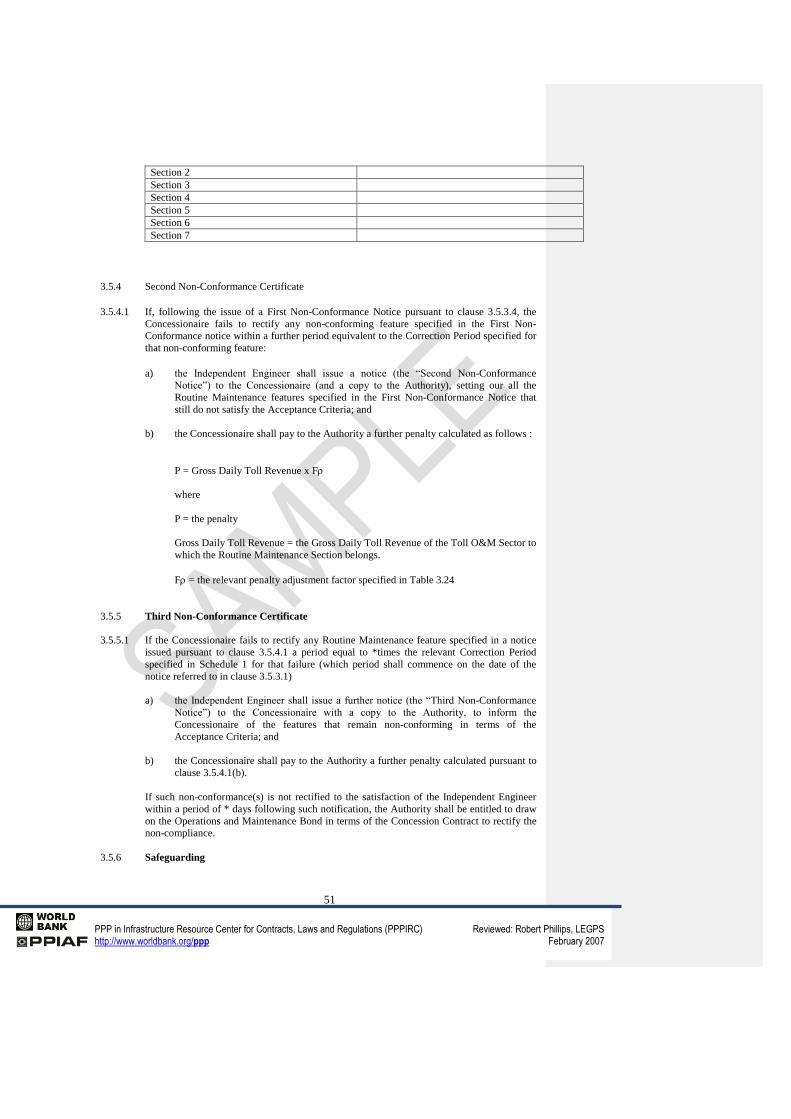
51
PPP in Infrastructure Resource Center for Contracts, Laws and Regulations (PPPIRC) Reviewed: Robert Phillips, LEGPS http://www.worldbank.org/ppp February 2007
Section 2
Section 3
Section 4
Section 5
Section 6
Section 7
3.5.4 Second Non-Conformance Certificate
3.5.4.1 If, following the issue of a First Non-Conformance Notice pursuant to clause 3.5.3.4, the
Concessionaire fails to rectify any non-conforming feature specified in the First Non-
Conformance notice within a further period equivalent to the Correction Period specified for
that non-conforming feature:
a) the Independent Engineer shall issue a notice (the “Second Non-Conformance
Notice”) to the Concessionaire (and a copy to the Authority), setting our all the
Routine Maintenance features specified in the First Non-Conformance Notice that
still do not satisfy the Acceptance Criteria; and
b) the Concessionaire shall pay to the Authority a further penalty calculated as follows :
P = Gross Daily Toll Revenue x F
where
P = the penalty
Gross Daily Toll Revenue = the Gross Daily Toll Revenue of the Toll O&M Sector to
which the Routine Maintenance Section belongs.
F = the relevant penalty adjustment factor specified in Table 3.24
3.5.5 Third Non-Conformance Certificate
3.5.5.1 If the Concessionaire fails to rectify any Routine Maintenance feature specified in a notice
issued pursuant to clause 3.5.4.1 a period equal to *times the relevant Correction Period
specified in Schedule 1 for that failure (which period shall commence on the date of the
notice referred to in clause 3.5.3.1)
a) the Independent Engineer shall issue a further notice (the “Third Non-Conformance
Notice”) to the Concessionaire with a copy to the Authority, to inform the
Concessionaire of the features that remain non-conforming in terms of the
Acceptance Criteria; and
b) the Concessionaire shall pay to the Authority a further penalty calculated pursuant to
clause 3.5.4.1(b).
If such non-conformance(s) is not rectified to the satisfaction of the Independent Engineer
within a period of * days following such notification, the Authority shall be entitled to draw
on the Operations and Maintenance Bond in terms of the Concession Contract to rectify the
non-compliance.
3.5.6 Safeguarding
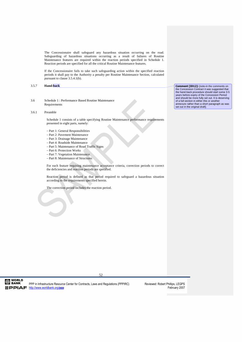
52
PPP in Infrastructure Resource Center for Contracts, Laws and Regulations (PPPIRC) Reviewed: Robert Phillips, LEGPS http://www.worldbank.org/ppp February 2007
The Concessionaire shall safeguard any hazardous situation occurring on the road.
Safeguarding of hazardous situations occurring as a result of failures of Routine
Maintenance features are required within the reaction periods specified in Schedule 1.
Reaction periods are specified for all the critical Routine Maintenance features.
If the Concessionaire fails to take such safeguarding action within the specified reaction
periods it shall pay to the Authority a penalty per Routine Maintenance Section, calculated
pursuant to clause 3.5.4.1(b).
3.5.7 Hand-back
3.6 Schedule 1 : Performance Based Routine Maintenance
Requirements
3.6.1 Preamble
Schedule 1 consists of a table specifying Routine Maintenance performance requirements
presented in eight parts, namely:
Part 1: General Responsibilities
Part 2: Pavement Maintenance
Part 3: Drainage Maintenance
Part 4: Roadside Maintenance
Part 5: Maintenance of Road Traffic Signs
Part 6: Protection Works
Part 7: Vegetation Maintenance
Part 8: Maintenance of Structures
For each feature requiring maintenance acceptance criteria, correction periods to correct
the deficiencies and reaction periods are specified.
Reaction period is defined as that period required to safeguard a hazardous situation
according to the requirements specified herein.
The correction period includes the reaction period.
Comment [ID12]: [note-in the comments on the Concession Contract it was suggested that the hand-back procedure should start some 3-5 years before expiry of the Concession Period and should be more fully set out. It is deserving of a full section in either this or another annexure rather than a short paragraph as was set out in the original draft].
53
PPP in Infrastructure Resource Center for Contracts, Laws and Regulations (PPPIRC) Reviewed: Robert Phillips, LEGPS http://www.worldbank.org/ppp February 2007
SCHEDULE 1
PERFORMANCE BASED MAINTENANCE REQUIREMENTS
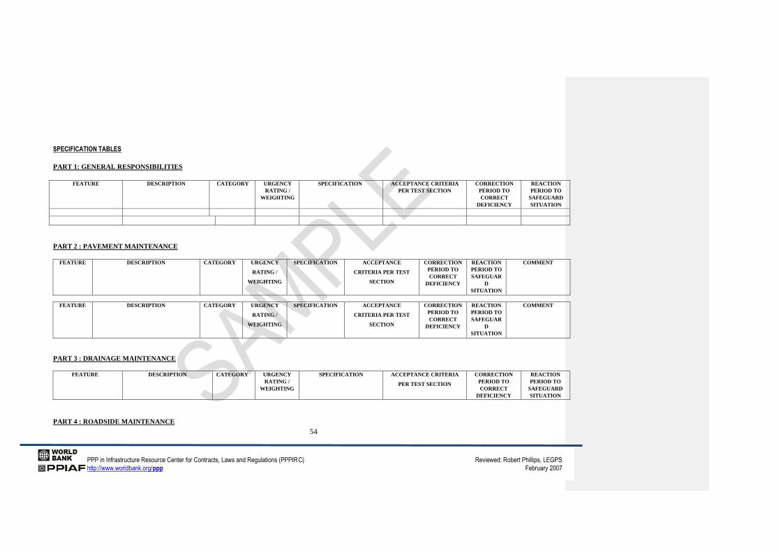
54
PPP in Infrastructure Resource Center for Contracts, Laws and Regulations (PPPIRC) Reviewed: Robert Phillips, LEGPS
http://www.worldbank.org/ppp February 2007
SPECIFICATION TABLES
PART 1: GENERAL RESPONSIBILITIES
FEATURE DESCRIPTION CATEGORY URGENCY
RATING /
WEIGHTING
SPECIFICATION ACCEPTANCE CRITERIA
PER TEST SECTION
CORRECTION
PERIOD TO
CORRECT
DEFICIENCY
REACTION
PERIOD TO
SAFEGUARD
SITUATION
PART 2 : PAVEMENT MAINTENANCE
FEATURE DESCRIPTION CATEGORY URGENCY
RATING /
WEIGHTING
SPECIFICATION ACCEPTANCE
CRITERIA PER TEST
SECTION
CORRECTION
PERIOD TO
CORRECT
DEFICIENCY
REACTION
PERIOD TO
SAFEGUAR
D
SITUATION
COMMENT
FEATURE DESCRIPTION CATEGORY URGENCY
RATING /
WEIGHTING
SPECIFICATION ACCEPTANCE
CRITERIA PER TEST
SECTION
CORRECTION
PERIOD TO
CORRECT
DEFICIENCY
REACTION
PERIOD TO
SAFEGUAR
D
SITUATION
COMMENT
PART 3 : DRAINAGE MAINTENANCE
FEATURE DESCRIPTION CATEGORY URGENCY
RATING /
WEIGHTING
SPECIFICATION ACCEPTANCE CRITERIA
PER TEST SECTION
CORRECTION
PERIOD TO
CORRECT
DEFICIENCY
REACTION
PERIOD TO
SAFEGUARD
SITUATION
PART 4 : ROADSIDE MAINTENANCE
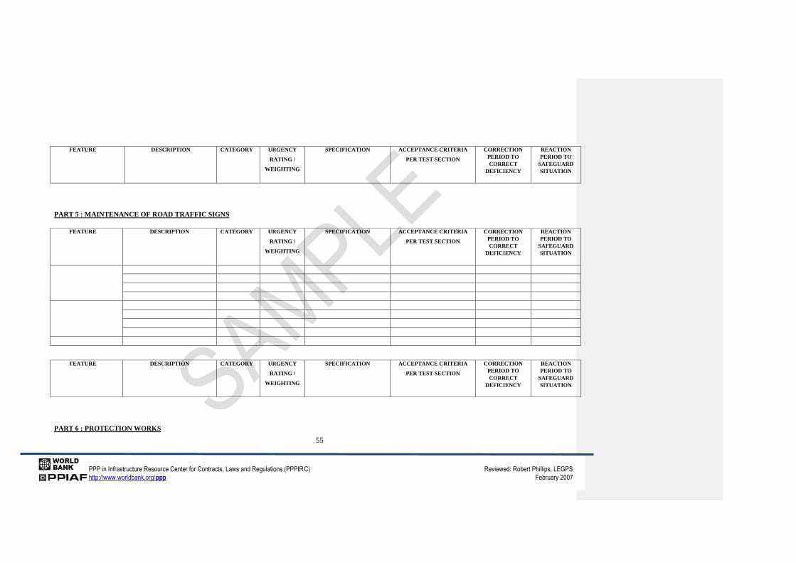
55
PPP in Infrastructure Resource Center for Contracts, Laws and Regulations (PPPIRC) Reviewed: Robert Phillips, LEGPS
http://www.worldbank.org/ppp February 2007
FEATURE DESCRIPTION CATEGORY URGENCY
RATING /
WEIGHTING
SPECIFICATION ACCEPTANCE CRITERIA
PER TEST SECTION
CORRECTION
PERIOD TO
CORRECT
DEFICIENCY
REACTION
PERIOD TO
SAFEGUARD
SITUATION
PART 5 : MAINTENANCE OF ROAD TRAFFIC SIGNS
FEATURE DESCRIPTION CATEGORY URGENCY
RATING /
WEIGHTING
SPECIFICATION ACCEPTANCE CRITERIA
PER TEST SECTION
CORRECTION
PERIOD TO
CORRECT
DEFICIENCY
REACTION
PERIOD TO
SAFEGUARD
SITUATION
FEATURE DESCRIPTION CATEGORY URGENCY
RATING /
WEIGHTING
SPECIFICATION ACCEPTANCE CRITERIA
PER TEST SECTION
CORRECTION
PERIOD TO
CORRECT
DEFICIENCY
REACTION
PERIOD TO
SAFEGUARD
SITUATION
PART 6 : PROTECTION WORKS
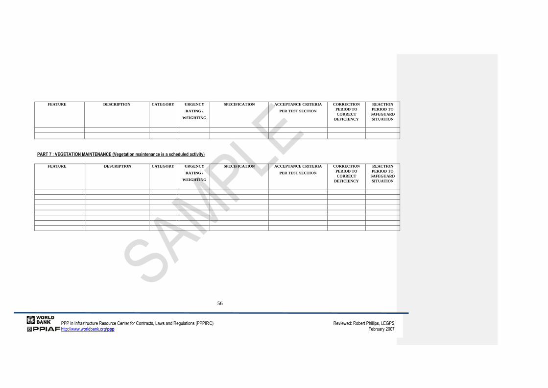
56
PPP in Infrastructure Resource Center for Contracts, Laws and Regulations (PPPIRC) Reviewed: Robert Phillips, LEGPS
http://www.worldbank.org/ppp February 2007
FEATURE DESCRIPTION CATEGORY URGENCY
RATING /
WEIGHTING
SPECIFICATION ACCEPTANCE CRITERIA
PER TEST SECTION
CORRECTION
PERIOD TO
CORRECT
DEFICIENCY
REACTION
PERIOD TO
SAFEGUARD
SITUATION
PART 7 : VEGETATION MAINTENANCE (Vegetation maintenance is a scheduled activity)
FEATURE DESCRIPTION CATEGORY URGENCY
RATING /
WEIGHTING
SPECIFICATION ACCEPTANCE CRITERIA
PER TEST SECTION
CORRECTION
PERIOD TO
CORRECT
DEFICIENCY
REACTION
PERIOD TO
SAFEGUARD
SITUATION
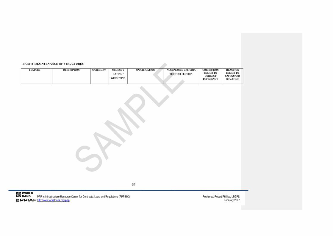
57
PPP in Infrastructure Resource Center for Contracts, Laws and Regulations (PPPIRC) Reviewed: Robert Phillips, LEGPS
http://www.worldbank.org/ppp February 2007
PART 8 : MAINTENANCE OF STRUCTURES
FEATURE DESCRIPTION CATEGORY URGENCY
RATING /
WEIGHTING
SPECIFICATION ACCEPTANCE CRITERIA
PER TEST SECTION
CORRECTION
PERIOD TO
CORRECT
DEFICIENCY
REACTION
PERIOD TO
SAFEGUARD
SITUATION
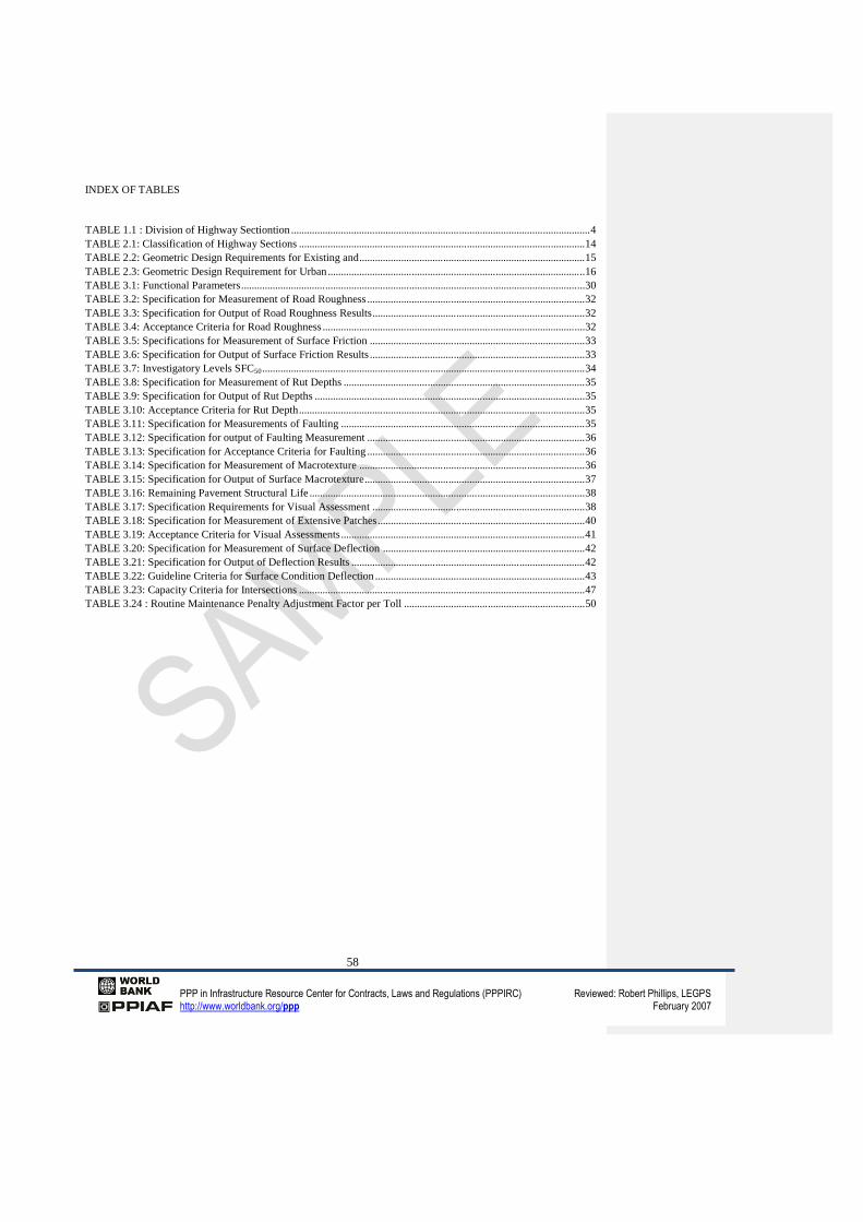
58
PPP in Infrastructure Resource Center for Contracts, Laws and Regulations (PPPIRC) Reviewed: Robert Phillips, LEGPS http://www.worldbank.org/ppp February 2007
INDEX OF TABLES
TABLE 1.1 : Division of Highway Sectiontion .................................................................................................................. 4
TABLE 2.1: Classification of Highway Sections ............................................................................................................. 14
TABLE 2.2: Geometric Design Requirements for Existing and ...................................................................................... 15
TABLE 2.3: Geometric Design Requirement for Urban .................................................................................................. 16
TABLE 3.1: Functional Parameters ................................................................................................................................... 30
TABLE 3.2: Specification for Measurement of Road Roughness ................................................................................... 32
TABLE 3.3: Specification for Output of Road Roughness Results ................................................................................. 32
TABLE 3.4: Acceptance Criteria for Road Roughness .................................................................................................... 32
TABLE 3.5: Specifications for Measurement of Surface Friction .................................................................................. 33
TABLE 3.6: Specification for Output of Surface Friction Results .................................................................................. 33
TABLE 3.7: Investigatory Levels SFC50 ........................................................................................................................... 34
TABLE 3.8: Specification for Measurement of Rut Depths ............................................................................................ 35
TABLE 3.9: Specification for Output of Rut Depths ....................................................................................................... 35
TABLE 3.10: Acceptance Criteria for Rut Depth ............................................................................................................. 35
TABLE 3.11: Specification for Measurements of Faulting ............................................................................................. 35
TABLE 3.12: Specification for output of Faulting Measurement ................................................................................... 36
TABLE 3.13: Specification for Acceptance Criteria for Faulting ................................................................................... 36
TABLE 3.14: Specification for Measurement of Macrotexture ...................................................................................... 36
TABLE 3.15: Specification for Output of Surface Macrotexture .................................................................................... 37
TABLE 3.16: Remaining Pavement Structural Life ......................................................................................................... 38
TABLE 3.17: Specification Requirements for Visual Assessment ................................................................................. 38
TABLE 3.18: Specification for Measurement of Extensive Patches ............................................................................... 40
TABLE 3.19: Acceptance Criteria for Visual Assessments ............................................................................................. 41
TABLE 3.20: Specification for Measurement of Surface Deflection ............................................................................. 42
TABLE 3.21: Specification for Output of Deflection Results ......................................................................................... 42
TABLE 3.22: Guideline Criteria for Surface Condition Deflection ................................................................................ 43
TABLE 3.23: Capacity Criteria for Intersections ............................................................................................................. 47
TABLE 3.24 : Routine Maintenance Penalty Adjustment Factor per Toll ..................................................................... 50


![DATED The [ ] Ports Authority - and - CONCESSION ...ppp.worldbank.org/public-private-partnership/sites/ppp...CONCESSION AGREEMENT For [_____] a BOT Container Terminal the Port of [_____]](https://img.pdfslide.us/doc/110x75/5ab8d3847f8b9ac1058d1b36/dated-the-ports-authority-and-concession-ppp-agreement-for-a.jpg)