Embed Size (px)
Citation preview

Terms and Conditions of Use:
this document downloaded from
vulcanhammer.infothe website about Vulcan Iron Works Inc. and the pile driving equipment it manufactured
All of the information, data and computer software (“information”) presented on this web site is for general information only. While every effort will be made to insure its accuracy, this information should not be used or relied on for any specific application without independent, competent professional examination and verification of its accuracy, suit-ability and applicability by a licensed professional. Anyone making use of this information does so at his or her own risk and assumes any and all liability resulting from such use. The entire risk as to quality or usability of the information contained within is with the reader. In no event will this web page or webmaster be held liable, nor does this web page or its webmaster provide insurance against liability, for any damages including lost profits, lost savings or any other incidental or consequential damages arising from the use
or inability to use the information contained within.
This site is not an official site of Prentice-Hall, Pile Buck, or Vulcan Foundation Equipment. All references to sources of software, equipment, parts, service or
repairs do not constitute an endorsement.
Visit our companion sitehttp://www.vulcanhammer.org
RECBWT VEaP DmxwmmmS Prank ~auschel, George G. ~ o b l e ~ , and Garland E. ~ i k i n ~ ,
INTRODUCTION
During the paat ten yeare, pile driving analysis by tbe wave equation has become a widely acaegfsd metbod. Ths Federal Highway Administration of the United States Department at Tr~nrgorthtion damervam mpecial credit for its erforte %a tbe diameminrrtion of wave mquat ton know-bow by providing
o program and d o a w n t a t i o n packager, o workohops and reminarr, and o rupport for further reeearch and development.
New programe and manuelm heve recently been released which greatly expands the versatility of the spproach. The new releaae includes addi t ional opt ions , results from correlation utudiea, input and output program6 and other enhaaaements. It a180 contain8 changee which may produce result6 which d i f f e r from those produced by other var~ ione .
Tbia paper describes the lataet WRAP developments, discussas the fmpact of eottware changea and highlight8 some of the new options. It i e hoped that th i s information will a i d the engineer fn makfng the best use of the avail- able data and aoftware, that it will contribute to accurate predictions and that it w i l l help t o avoid misinterpretationr.
BACKGROUND
The wave equation approach wae originally developed by Smith 11960) who pre- merited complete numerical analysis model far harmer, driving mystem, p i l e and moil& Smith also racommendsd parsmeterr for variour ryrtem eompenents including the moil baeed on hie experience with the Raymond Company.
Several researcbsru further inveatigatad the ideas of Smith and further extandsd the concept. A t the Texas Transportation Iaetitute, the TTI program wen developed and included in the FWWA software package, (Hirsch, Carr, and Lowery J r . , 1975). The WgAP program (Goble and Rau~ebe, 1976), wan developed mtartfng in 1974 after it becanre evident that the basic Smith and TTI approacb were inadequate for the atlalyriu of dieael hamaera. A large amount of f i e l d data (Gobla, e t al., 1975) 0168 available to the suthora of WgaP and the program warn thoxou8hly tasrted by ownparison w i t h f i e l d r&aulre. WEAP not only provided tha uaer with an Improved hamper model but a l s o with a simpli- i i r d data input. For example, data for moat common hammere was stored in a tile and could be recalled by mimply upecifping the hamar identifying num- ber. Tbe numerical mpring/maee p i l e mods1 wan automatically prrgered from the area and modulur vermua length data. Even tho mil r e r i r t m c e dietribu- tion could br entered in a vary basic form and aevaral common distrfbutiane ware mtored for quick recall, tharmby eliminating the nerd for oaloulatioas by tha unar and reducing the poraibi l i ty of errors.
Frank Raumaha, Prsmident , Raumche Likine and Amnociatea, Ine. George 0. Qoble, Protbrraor, Civil Engfnaeriag, University of Colorado Garland Likinr, Pramidant, P i l e DynamSos, Xno.
Da6pite the proven accuracy of Smith'a pi l e model, the realiem of W3hP1s diesel anmiymie, and the uccumulatsd sxpsrfsnce with the wave equntlonlB eoi l parametera, the need tor further work warn evident. Thus, i n 1981 a first WEAP update was made which included an expandad Uaers Manual.
Developments in microcomputer technology, new harmer typeo, new measurement reeultr, research a t the Univsr~fty of Colorado in Boulder (Hery, 1983) and a etudy on M r performance (Rauachu at al., 1985) muggeatbd Lurtber updating of WEULP. This new program waa presented togather with a new ee t o f manuals (Goble and Uauscbe, 1986). Differences between WEBP end WRAP86 were deeeribed by Rausehe, et al., {1986) .
After a one year tr ia l period, umer axwrieacen ware ineluded i n a slfghtly revised 1987 version of -86. The revised manual aleo contained reeults from an sxtanmive study on the calculated and actual performance o f diesel hamuers . During th ir tima period, additional features were incorporated into the pra- gram in a verrion called ORLWEbP. Preproceasing and postproceesing programs were implemented or improved f o x the PC veroion. With these features, easy sccemrr t o the wave equation war provided to virtually any interested peraon and working witb the program bas been greatly aimplitied. However, it is #till important that the user of the analysis results fa thoroughly familiar with p i l e driving practice, with soil rpechanico, and with the mtrcbnoics of the wave equation approach.
W 8 6 wae alao compared with the earlier WBAP program (Rauache, et al,, 1986). Important new fatutsm were
o Atomized Fuel f nj action Model
o Reeldual Strera Analysis Model
o Addittonal Hamwr Data
o Improved Slack/Splice Model
o PC Application Including Graphics
o Driv ing System Data Collection
In 1987, the following main features ware added.
o Dieeel Hammer Pexformaacs Study o Xnergeeed Speed for Dieeel Analyees o Efficiency Raduction for Battered Pile Driving o BearLng Graph Program for Screen or Plotter
The 1987 releaee alrto includes editorial changes in both code and docmenta- t i o n , mome h m x data sets were corrected or inconsimtenciea were removed. An alternative hmmer data t i l e wee also prepared containing parameters used in the diemel hammer performance atudy.
In thf8 program veraion, the VEAP ruthorri now provide the user w i t h a choice of either SI or Rnglfeh units and with further flexibility for often encourt- tered situations which do not require the ~tandard bearing graph output, Important new features are
o Automatically varied stroke for constant capacity
o Automatic snalysia at various p i l e toe penetration# witb computation o f driving t i m e
o Englieh (kip-f t - fnah-hi) or SI (W-m-ram-ma) units within the same program.
o Maximum number of p i l e aegmsntr at 299 rrtbnr than 99 allowin analysis of p i l e a up to 550 rn (1800 ft) rather than 180 rn (600 ft! long.
These additional feature8 cauamd the program to exceed the FKWA upeciffed 256 ksyte memory. For thia reason, the new program was daveloped on a proprietary basis. B r i e f descr ipt ions of the new opt ions follow.
The Varied Stroke - Conatant Capacity Option
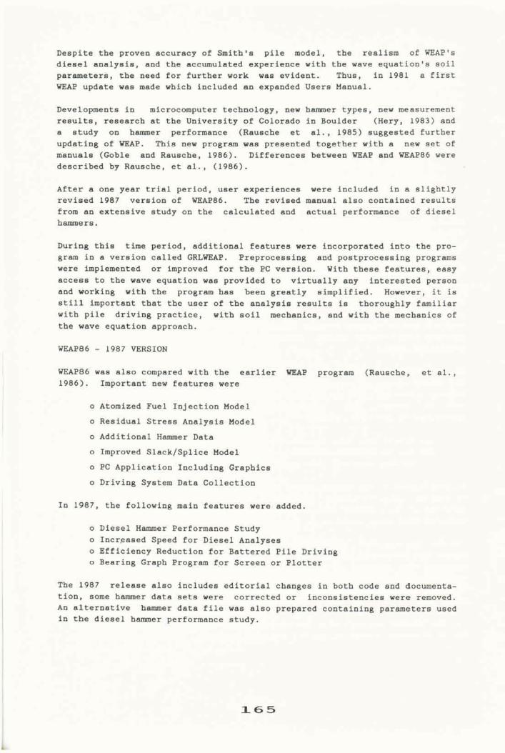
For diesel harmers, the driving criterion ia often linked t o stroka for verification of harmer performance. Typically, however, wave equation analysee are made tor a series oi! increering bearing capacity values w i t h either f i x e d or varying mtrokea and a bearing graph is made wbieh only includes one useful point : blow count for the des i red capacity at one particular mtroke.
To demonstrate both canventlonal and new approaches, Example 1 contained in the WEAPBb manual was reanalyzed. This case represented a Delmag I) I2 baromer driving a 40-foot (12.2 m) 12 x 53 H-pile i n t o granular soil for a 45-ton (408 kW) des ign load. Three analyses were performed to demonstrate the approachee o f past and preeent,
(6) Tradit ional Wave Equation Analys i s witb fixed stroke (b) Coriventfoual WEAP Analysis with variable stroke ( c ) GRLW&AP Analysis with f i x e d ultimate capaci ty
a) Traditionally, the harmer atrake 161 t ixed a t the rated stroke and a series o f bearing capacity valuer i e analyzed. The capacity is then plotted as a function of the computed blow count. ( F i g . la). For a 90-ton capacity, tbe required blow count would be 2 1 blows per foot ( 2 1 blow6/0.3 m).
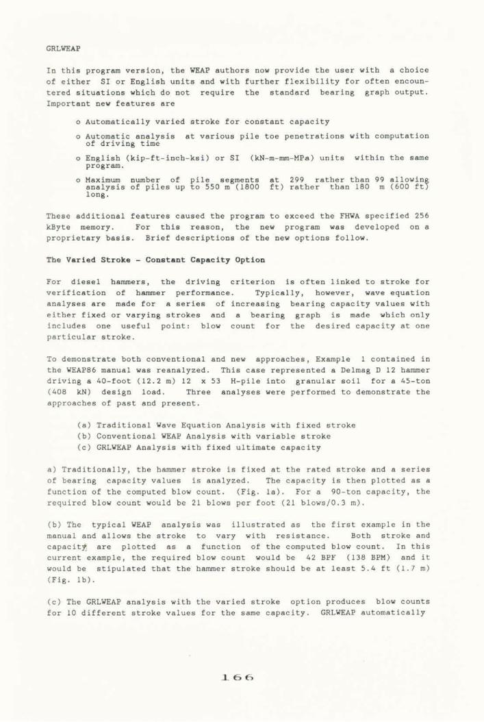
(b) The typical WgAP analysis was illustrated ae the first: example in t b s manual and allows the stroke to vary with reaimtance. Both stroke and capacity are plotted as B function of tbe computed blow count, In t h i s currant example, the required blow count would be 42 BPF (138 BPM) and it would be stipulated that tbe hammer stroke ahould be at least 5.4 ft ( 1 . 7 rn) { F i g . Ib) .
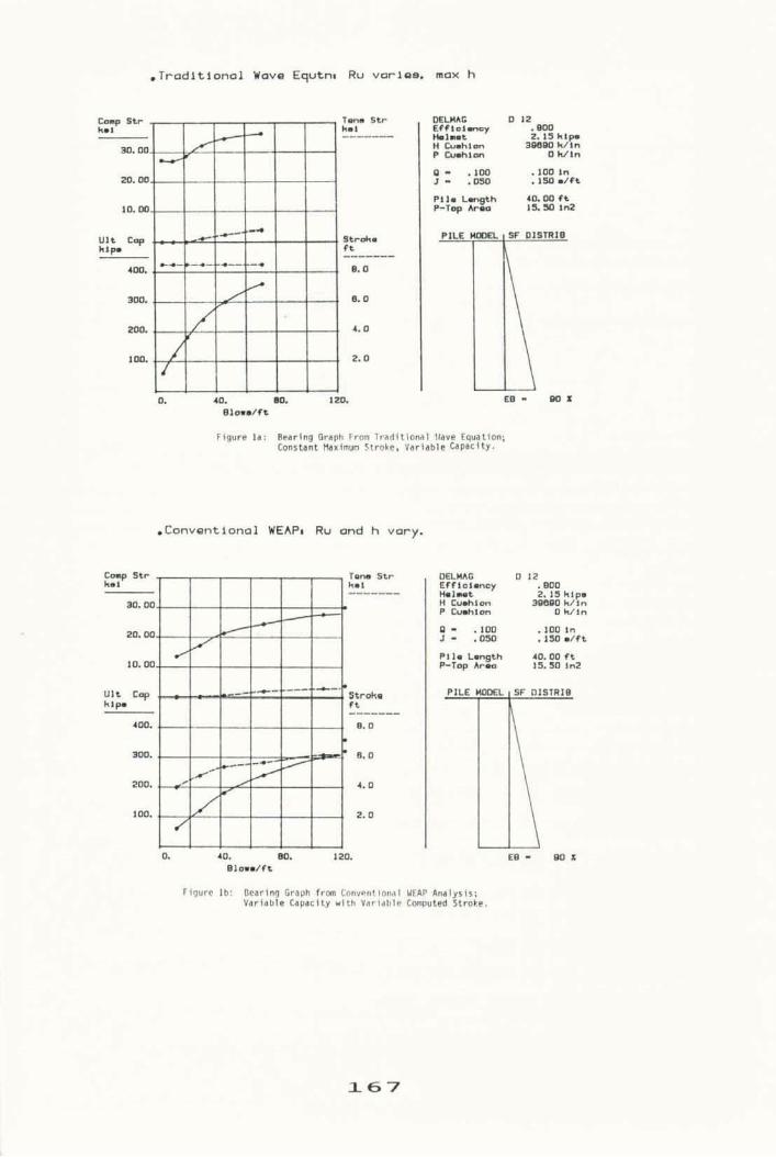
( c ) The GRLWEhP analpsim witb the varied rtroke option produces blow counts for 10 different stroke values for tbe same capaci ty . GRLWWP automatically
,Traditional Wave Equtne Ru varima. mox h
Ftgura la: Berrfng Qmph fron Tradl Constant thxlmn Stroke,
tlonhl llava Equation; , Variable U P C l t y .
.Convantional WEAP* R u and h vary.
Figure lb : Pearln Gnph frm Convsntlonal ~a r iab?a Capacity with Variable
a - .1m . loo In J e .aa ,150 dct
P 1 h Lm@ 4D,W fa P-Tmp hau IS. 50 ln2
HEAP Analysis; twuted Stwke.
adjueta the fuel preesureri such thst downward and upward rtrokea match. In tha f i e l d , the inspector would obeeme the hslamer atroke e.g., by meana o f a Saximater, and would then datemine the mintmum required blow count from the ~ t r o k e ve. blow count p l o t (Fig. lc).
The wuve equation uaer ehould exercise caution and check the pile streaa levels in all three examples. Of course, in saslpois type (a) s reaaalyria with a lower stroke would be necessary if otreaoaa are exca8uiva; 5n (b) the hammer pressure m y be reduced i t ~trea8es ara too high a t the 8peciSied capacity. fn ( c ) mtrokes with high rtrarrru ate uimply diuallowad and the hamner must be run at a lower fuel oe t tgng to obtain correspondingly lower atrokee and higher blow countm.
In a conventional drivablity analyeis, the moil atrength 5 8 umually calcu- lated for a p i l e penetration of particular interest. The ohatt xeuiotaace percent.&+, shaft remiutanee dfstribution, and soil parameters such as damping aad quake are met to the oalue~ approprfate for the depth considered. Attar analyzing a oeriaa of capacitieu, a bearing graph is constructed and blow count^ are gelacted not only for the investigated depth but aleo for othmru in the ne5ghborbaod or over the whole extent of p i l e penetration.
For p i l e drivabl i ty analymia, th ie aimple procesa is not eatisfactory becauee S t lack8 accuracy and many bearin8 graphe ehould be produced to properly cover the total range of p i l e penetration. G R L W now allowe the program ueer t o input the following quantities for up t o twenty different elevations.
o Shaft Resistance per Unit h p t h
o Toe Bearing
o Sbaft and Toe Quakes
o Shaft and Toe Damping
l a k i p
€u* P O X
O l d C h Figure lc: Stroke vs. B lcu b u n t Frar GRLYERP for Fixed Capaclty o f laO kips.
Instead of epecitying a sequence of capacity values, the urar anterr up to ten depth penetration for which an malyais i a t o be performed together with up to s i x eo-callad ahaft realfstance modifications factore. For the first depth, the program utwa the soil input data t o determine toe bearing, toe quake and toe damping all by interpolation, shaft rerai~tenee by rumation and shaft quake and damping by weighted averaging, The first aheft resietance modification factor is applied to the total ehaft resistance. The static weighte, preloading the p i l e before impact, are aubtraeted in a proportional manner from shaft and toe bearing. Theue subtracted wcightm include the hammer 81389mbly, cap, and the p i l e above grade.
The f i r s t wave equation analpsi8 ie now performed and the blow count obtained. Then, the second shaft resistance modification factor fs applied, an analys is i s again performed and repeated until all modification factors for the first pile dtptb have been analyzed. A suolmary, for a first standard bearing graph relating blow count to capaci t iee with constant toe bearing and svaflable ekin fr ic t ion , fa then printed. The program then continue5 to aaa- lyze the second and otbar depth valuer in a similar manner. A f i n a l sumnary is included for each modification factor. This summary gives tom bearing, blow count, atrema maxima, blow rate (blows per minute; variable for diemla) and total driving time for each shaft resiatrace modification factor.
for PC applications, a file musrt be generated which the wave equation program reads and analyzes. The original W 8 6 package imcluded W86IN which guided the user through all neeeesary input phases. Later, MENU wel written which included an extenrliva tutorial; this progxam is recommended for the novice to wave equation analysis. Finally, TEMPUTX was developed which includes a l l data t n b l e s of the manual in it^ wHelp-Filesw. This latter program makes hamer data file eearches rod maintenance particularly convenient.
Preeentation of plotted wave equation result^ i~ much more informative than e l i s t i n g of numerical, values. A progrnm wae therefore prepared for either screen or plotter graphice, The individual p l o t s that t h i s program produces are
o Force and Velocity at pile bead a@ a function of t i m e .
o Three eeleeted variables like Forces, Di~placemente, Accelerations, and Velocities in hammer or p i l e 88 a function of time.
o Pile Variables vs. Time and Length (3-dimensional).
o Bearing Graph
o Stroke vs. Blow Count for a particular capacity.
o Capaeitiea, Strensaa, Blow Count vs. Depth.
GRLWEAP also includes screen graphics of bearing graph and user selectable variables as they are being computed.
DIESEL STUDY
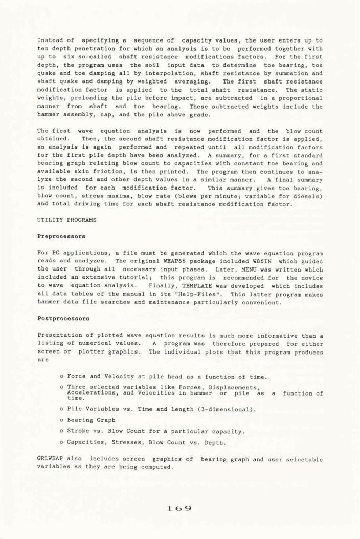
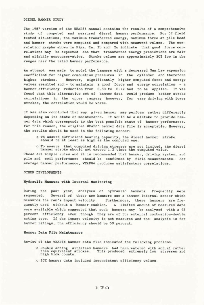
The 1987 vermion of the W 8 6 manual containa the reaultm of a compreheaeive study of oomputed and masured diesel harrmsr performance. For 57 tield teeted situationa, the maximum transtarrsd energy, maximum Ioree at pile bead and harmer stroke were computed and compared with measured valuea. The cor- relation graph6 ehown in Figm. 2a, 2b and 2c indicate tbat good force cor- relations may be expected and tbat traneferred energy predfet iona are fair and slightly nonconssrvative. Stroke value^ are approximately 20s low in the ranges near the rated hamer periormance.
An attempt war made to model the hamera with a decreauad Ga6 Law expaorion coefficient for bigher combuetioa prsssuxea ia the cyl inder and therefore higher strokes. However, 6ignISicantly higher computed force and energy value5 resulted and - to maintain n good force and energy correlation - a hamor efficiency reduction from 0.80 to 0 .72 had to be epplied. It was found that t h i s alternative aet of hamner data would produce better mtruke correlations i n the upper rangem; however, for easy driving with lower strokes, the correlation would be worm.
It was also concluded that any given hamper may perform rather differently depending on i t 8 atate o f maintenance. I t would be a m i a t a h t o provide ham- mer datm which corresponds t o the best possible state 02 hamer psrformanca. For this reaeon, the original W 8 6 bamer data fils i r acceptable. However, the result8 ehwld be uaed in the following manner:
o To assure suttfciatlt bearing ea ac i ty , the diesel hammer stroke mhould be a t l e a s t am high am rEe computed one.
o To assure that corn uted driving 8treseee are not l i m i t e d the diemel hammer .troll( ahoul# not e x ~ e e d I . 2 timaa the computed r d u e .
These are simple rulea and it is reconmended that burner, driv ing system, and pile and moil performance ahould be confirmed by f i e l d meaeuremcnte. For average hammsr performance, -86 producea satisfactory eorr*lbtions.
OTHER DEPEMFMEN!I!S
Hydraulic . e r a with Xnterml Moaitoring
During the past year, analyaea of hydraulic hammers frequently were requested. Several of these new hanmera urns a hammsr-internal sensor whieh measures tba ramtu impact velocity. Furthermore, theme hammer6 are fre- quently uutd without a hamner cushion. A limited amount of measured data were available which suggested that such hammsre may be analyzed with a 95 percent efficiency even though they ate of the external combuetion-double acting type. If the 5mgact veloci ty i6 not meaeured and the analyafs is for b m e x ratings, the ef f ic iency should be SO percent.
HslPpWr Data Pile Maiatmnancm
Review of the W 8 6 hammer data file indicated the following problema.
o Double acting airlsteam bamtrs had been entered w i t h actual rather than ufvalent stfokea. This produced extremely low streeses and high b4ow count^.
o ICE h-r data included inconsietent efficiency valuee.
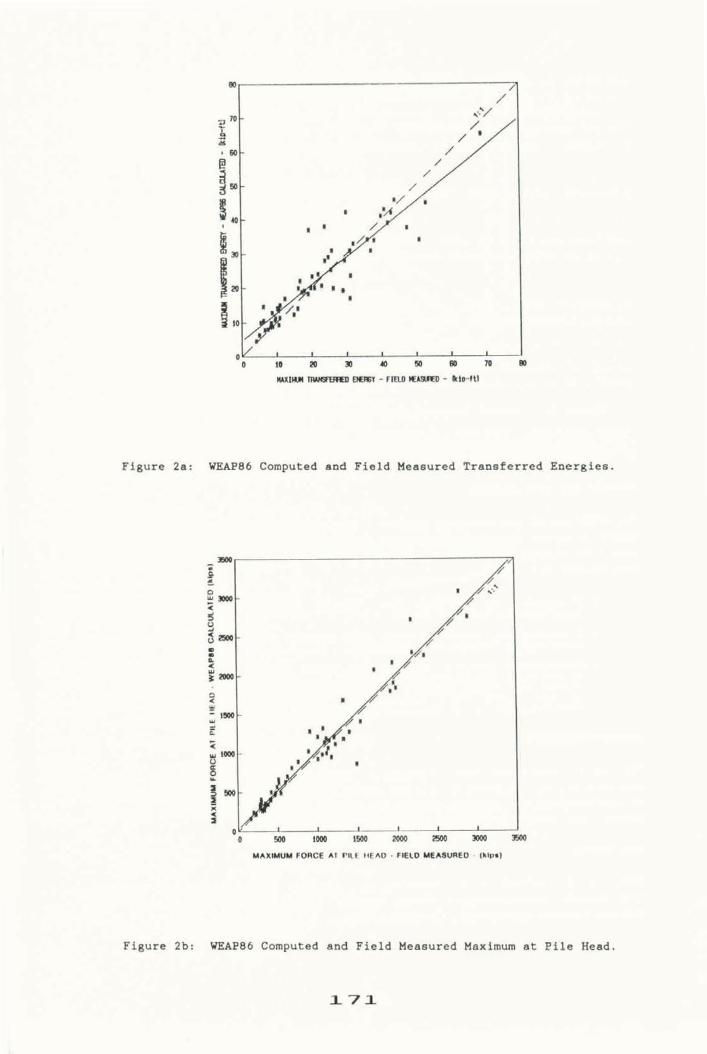
Figure 28: -86 Computed and Field Measured Traneferred Energies.
- b 6 # I O D l m ~ m B W O -
WAX- FOllEe A1 PILE t e A O * CYLO YTMUACD * IUICn)
Figure 2b: -86 Computed and F i e l d Measured Maximum st P i l e Head.
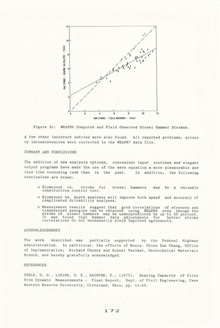
Figure 2c: -86 Computed and F i e l d Obaerved Diesel H a m e t . stroke^.
A few other incorrect entries were also found. All reported problem^, arrorg or inconsistencies were corrected in the WRAP87 date file.
SOPlMARY ANJI CONCLUSIONS
!The addition of new analys is opt ions , convenient input routines and elegant output progrems have made the urre o f the wave equation a more pleasurable and lees time consuming task than in the past. In addition, the following conclue ions are drawn 3
o Blowcount ve. atxoke for diesel hammers map be a valuable conatruetion control tool .
o Blowcount vs. depth analyser w i l l improve both speed and accuracy of oomplicated drivabffity analyses.
o Measurement results suggest that aod eorrelationu of etress~s end tran~ferred ener i e e can be obtain*! usio W 8 6 even though the stroke a t d i e B e f harmer. may be vnderpreaicted by up to 20 percent. It was found that hammer data ad ustmants for better stroke correlatians do aot neceesarfly y i e l d 4 raproved agreements.
The work described warn partially supported by the Federal Highway Administration. In particular, the effort5 of Hssrm. Chien Ten Chaag, Office of Tmplementation; Richard Cheaey and Suneel Vanikar, Geotecbnical Materials Branch, are hereby gratefully aobnowledged.
GOBLE, G. G., LIKINS, G. B., RAUSCHZ, P., (1975). Bearing Capacity of Piles From Dynamio Measuremerite - Final Report, Dept . of Civil Engineering, C a m Weatern Reeerve Uofverefty, Cleveland, Ohio, pp. 41-45.
GOBIg, G. G., and RAUSCEE, F., (1976). Wave Equation h a l y u i a of P i l e Dri- ving - WRAP Program, Vole. i thxwgh 4, =A IP-76-14.1 through IF-76-14.4.
W B U . G. Q . , and RhUSCHE, F., (1986). -86 Program Docmentation in 4 Vols. Premented to the Federal Highway Adminiatration, Office of Impler~entation, Wamhingtou, D. C. 20590.
HEf(Y, P., (1983). Rauidual, Strmue Analyuim in WEAP, HSCE Themfa, Wniverrify I of Colorado, Boulder, Calorudo.
HfRSCH, T. T., CARR, L., and UmERY JR. (1976). Pile Driving Analysis Wave Equation Ueerle Manuala; TTI Program, Vola. 1 through 4, M A IP-76-13.1
! throu&h IP-76-1.3.4.
RAWSCHE, F., LIKTHS, G., GOBLE G. G., and MINER, R., (1985). The Performance of Pile Driving Systeari, Submitted t o the Fedsral Highway Adminiratratiua, Wamhington, D. C. , Main Report, Vol. 4, pp. 2-38.
RAUSCHE, F., LXKI18, G * , HUSSEIN, M., (1986). Dynamic Analysis of Impact Driven Pilea by -86, Paper Prenented at FHWA Symposium on P i l e Group Performance, Waehington, D.C.
SMITH, E . A . L . , (1960). Pile Driving Analysiu by the Wave Equation, AS=, Journal of Soil Macharrice and Foundations Division, Vol . 8 6 , SH4, Paper No. 2574.