Embed Size (px)
Citation preview

This addendum accompanies your equipment documentation and is additional information concerning the heart rate features for your equipment and console.
ImportantThe heart rate features are intended for reference only. They may not be accurate for every user or at every speed and are not intended for use as a medical device. Holding the heart rate handle touch sensor while exercising at higher intensity may also decrease accuracy of the heart rate reading and is not recommended. Please also read your product documentation and visit: www.precor.com/en-us/customer-service/faq.
P/N 305324-101 rev A, ENU©Precor Incorporated | October 2017

EXPERIENCE™ SERIES AMTGETTING STARTED GUIDE
Welcome to a personalized fitness experience for your members
The Experience™ Series cardio line gives operators the proven, reliable performance they count on. Each piece delivers the personalized exercise experience and entertainment choices your members seek. The Adaptive Motion Trainer (AMT) keeps exercisers engaged, challenged, and loyal. For more information about the AMT, visit us at www.amtfitness.com.
Get to know Precor equipment
The AMT with Open Stride™ lets the exerciser adjust stride height from 6.8 to 10 inches (17 to 25 cm). Combine this with the AMT’s ability to dynamically adapt the exerciser's stride length from 0 to 36 inches (0 to 91 cm). Open Stride applies to AMT 800 models only. AMT with dynamic stride length applies to AMT 800 and AMT 700 models.
The StrideGuide™ diagram illustrates the ratio of stride length to stride height.
AMT offers a total body workout in one piece of equipment:
Handlebar positions are optimized for pushing and pullingmotions
Helps exercisers burn more calories with more enjoyment Monitor stride length with Stride Dial™
The AMT fully engages exercisers of all fitness levels with an infinite range of stride paths to create a uniquely effective low-impact workout, making every workout a personalized experience. Your members get boundless training variety without the need to change machines: improve aerobic and anarobic fitness, as well as strength, coordination, and balance on the AMT.
Get to know Precor cardio workouts
Our instructional videos provide information vital to the safe and effective use of the equipment and can help users, trainers, and operators get the most out of their EFX.
A variety of manual and preset programs such as Lose Weight, Be Fit, Get Toned, and Push Performance can help trainers and users meet their goals and build training programs tailored to produce the best possible results.
Instructional videos and complete EFX operating instructions are available at www.precor.com.
Also available at precor.com are regularly-updated blog posts with more ideas about fitness routines and advice from trusted industry experts.
AMT Getting Started Guide | P/N 304439-101 rev C, ENU ©2017 Precor Incorporated | June 2017

TRAINING AND EXERCISING
CAUTION Before beginning any fitness program, see your physician for a thorough physical exam. Seek advice from your physician to learn the target heart rate appropriate for your fitness level.
Read all safety and operating instructions included with your equipment. For more information, visit us at www.precor.com and look for your equipment model number.
Start a workout
Step 1: Place your hands on the fixed side rails and place a foot on each pedal to enter the equipment.
Step 2: Hold on to the stationary grips in the center.
Step 3: Start stepping in a vertical motion. Step 4: Press QuickStart (on screen for touchscreen consoles), or choose a preset workout, then press OK to begin.
Step 5: Adjust the left motion control to change your stride height in one of five levels. You can vary your stride style by lengthening your stride to a maximum of 36 inches.
Step 6: Adjust the right motion control to select a resistance level, (low for warming up and gradually higher as you start exercising).
Step 7: Press Pause to finish. To dismount safely, hold the fixed hand rails then slowly step off the AMT.
Check out our trend-based workouts and Precor product tutorials at www.precor.com/education.

Experience™ Series Adaptive Motion Trainer® (AMT®)
Assembly Guide
Equati on 1: Englis h

2

3
AMT Assembly Requirements
Start assembling the AMT while it is still on the pallet. Remove the AMT from the pallet when instructed to so in this guide.
Follow the steps in the order listed in this assembly guide. For more product information, visit us at www.precor.com.
WARNING At least two people are required to assemble the equipment. DO NOT attempt assembly by yourself.
Assembly requirements Important Before you fully tighten a fastener, check that its head is flush with the surface of the equipment. If not, cross-threading may have occurred. DO NOT attempt to rework the assembly as more damage to the equipment will occur. Instead, contact Customer Support at www. precor.com
We recommend you:
• Assemble the equipment close to where you plan to use it. • Assemble the equipment on a solid, flat surface, so that it remains level and
stable. • Locate the equipment at least 19.7 inches (0.5 meter) away from walls or
furniture on either side of the equipment, and 19.7 inches (0.5 meter) away from objects behind or in front of the equipment.
• DO NOT move the equipment without assistance.

4
Required tools Hardware kit
• #2 Phillips screwdriver • Rubber mallet • 7/16-inch open-end wrench • SAE standard socket set • Wire cutter • Two #1 Phillips screwdrivers • Torque wrench (including a
3/16-inch hex wrench bit)
Component Quantity Component Quantity
Nylon lock nuts (5/16-inch)
6 Screw (#10 x 1 1/4-inch)
10
Hex head bolts (5/16-inch x 1-inch)
4 Flat head hex drive screws (1/4-inch x 5/8-inch)
5
Hex head bolts (5/16-inch x 3 1/2-inch)
6
End caps 2
Bolt sleeve 2 Conduit (optional) 1
Flat Washer (5/16-inch)
6
5
Begin assembly
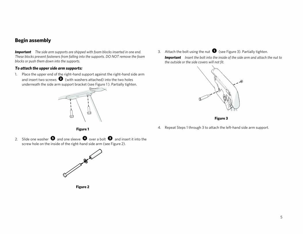
Important The side arm supports are shipped with foam blocks inserted in one end. These blocks prevent fasteners from falling into the supports. DO NOT remove the foam blocks or push them down into the supports.
To attach the upper side arm supports: 1. Place the upper end of the right-hand support against the right-hand side arm
and insert two screws (with washers attached) into the two holes underneath the side arm support bracket (see Figure 1 ). Partially tighten.
Figure 1
2. Slide one washer and one sleeve over a bolt and insert it into the screw hole on the inside of the right-hand side arm (see Figure 2).
Figure 2
3. Attach the bolt using the nut (see Figure 3). Partially tighten. Important Insert the bolt into the inside of the side arm and attach the nut to the outside or the side covers will not fit.
Figure 3
4. Repeat Steps 1 through 3 to attach the left-hand side arm support.

6
To attach the lower side arm supports: 1. Place the two side arm supports against the center support and insert a
narrow screwdriver through the middle holes of each side arm and the center support to keep them aligned (see Figure 4).
Figure 4
2. Slide a washer over each of the four bolts and then, from the opposite side of the center support, insert the four bolts and attach a nut to each bolt. Partially tighten the fasteners (see Figure 5).
Figure 5
3. Tighten the side arm supports to 160 in-lb (18 N-m) of torque. 4. Using a 9/16-inch open-ended wrench, loosen the jam nuts and extend
the adjustable feet on the side arm supports until they touch the floor; then remove the spacer block from under the back end of the AMT.
5. Remove and throw away the two #10 x 3/4-inch Phillips head screws securing the upper back corner of the inner plastic molding to the end of the right side arm.
Figure 6
6. Fit the right-hand inner and outer side arm covers to the right side arm. Insert five screws , then tighten them to 8 to 12 in-lb (1 to 1.35 N-m) using a #2 Phillips screwdriver (see Figure 7). Note Alternatively, tighten the screws until the two side arm covers are in full contact, then turn the screws an additional quarter turn.
Figure 7
7. Repeat Steps 4 and 5 to attach the left side arm.
7
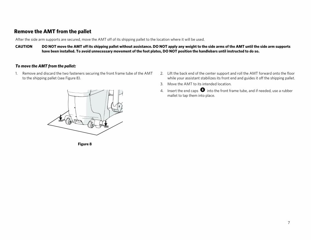
Remove the AMT from the pallet After the side arm supports are secured, move the AMT off of its shipping pallet to the location where it will be used.
CAUTION DO NOT move the AMT off its shipping pallet without assistance. DO NOT apply any weight to the side arms of the AMT until the side arm supports have been installed. To avoid unnecessary movement of the foot plates, DO NOT position the handlebars until instructed to do so.
To move the AMT from the pallet:
1. Remove and discard the two fasteners securing the front frame tube of the AMT to the shipping pallet (see Figure 8).
Figure 8
2. Lift the back end of the center support and roll the AMT forward onto the floor while your assistant stabilizes its front end and guides it off the shipping pallet.
3. Move the AMT to its intended location.
4. Insert the end caps into the front frame tube, and if needed, use a rubber mallet to tap them into place.

8
Remove the access covers Removing the front and side access covers provides sufficient space to install the console cables.
Note If you are installing a non-touchscreen console without a Personal Video System (PVS) or accessory cap, you do not need to remove the access covers.
Important Remove any ties or other materials that hold the side arms in place before the supports are installed.
To remove the access covers: 1. Lift the gasket upward and remove it from the center support (see Figure 9).
Figure 9
2. Extend a finger through the gasket opening and under the front edge of the top cover. While pressing upward on the top cover, use the heel of your hand to tap below its front edge and release it (see Figure 10). Repeat this step to release the other side of the top cover.
Figure 10
3. While holding up the front edge of the top cover, use the heel of your other hand to tap just below the back edge of the cover. Lift the cover up and out of the way.
4. Remove the two #10 x 3/4-inch screws from the bottom corners of the front cover assembly.
5. Gently press in on each of the side covers, just behind the front edge and about 8 1/2 inches from the bottom, while pulling the front cover assembly forward to disengage it. Note Each side cover has a small triangular mark to show you where to press.
6. Move the front cover assembly forward and slightly upward to remove it.

9
Rewire the AMT for a touchscreen console
DANGER DO NOT attempt to connect electrical power until all assembly procedures are complete and the console is properly installed.
Retrieve the following parts from the console package:
TV (coax) coupler
Ethernet (CAT 5) coupler and cable
Cable, and the console power cable
Important Make sure all cables pass through all of the cable clips and DO NOT allow any of the cables to hang near moving parts.
Note In the following steps, pass the console power cable through the opening first, followed by the TV cable. Pass the remaining cables through in order of connector size (see Figure 11).
Figure 11
Thread the cables for each part as follows:
1. TV connection : a. Install the TV (coax) coupler, star washer, and nut, into the jack plate at the
lower end of the AMT and tighten (see Figure 12). b. Connect the TV cable to the inside end of the TV cable coupler. Tighten the
connector using a 7/16-inch open-end wrench.
2. Ethernet connection : a. Attach the Ethernet coupler into the jack plate at the lower front of the AMT
(see Figure 12). b. Plug the Ethernet cable into the coupler.
3. Console connection : a. Plug the console power cable into the jack plate (see Figure 12). b. Slide the quick-disconnect terminal on the grounding lead of the power cable
over the grounding terminal on the equipment frame.
Figure 12
10
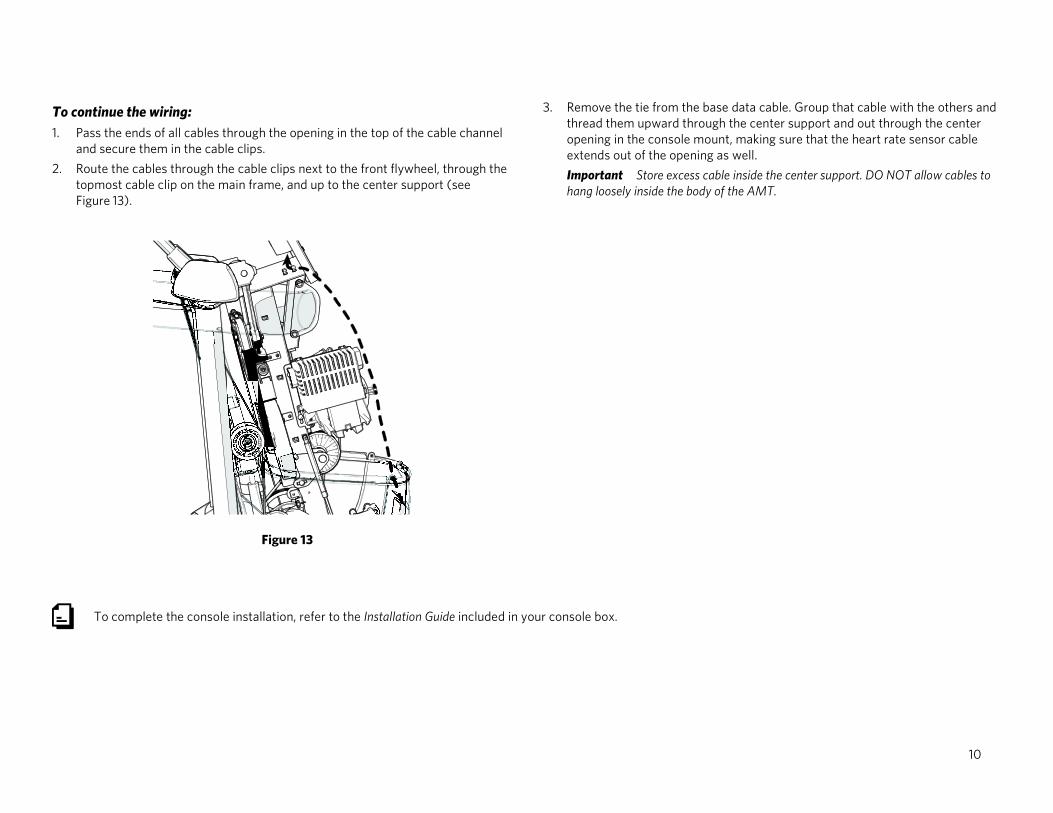
To continue the wiring: 1. Pass the ends of all cables through the opening in the top of the cable channel
and secure them in the cable clips. 2. Route the cables through the cable clips next to the front flywheel, through the
topmost cable clip on the main frame, and up to the center support (see Figure 13).
Figure 13
3. Remove the tie from the base data cable. Group that cable with the others and thread them upward through the center support and out through the center opening in the console mount, making sure that the heart rate sensor cable extends out of the opening as well. Important Store excess cable inside the center support. DO NOT allow cables to hang loosely inside the body of the AMT.
To complete the console installation, refer to the Installation Guide included in your console box.

11
Route cables under the rear pedestal (optional) When the AMT faces away from the cable raceway, use the conduit included in the hardware kit to route the Ethernet, TV, and power cables underneath the center of the AMT and through its rear pedestal.
To use the conduit: 1. Lay out the cables so that they pass directly under the center support of the
AMT and place the conduit on the floor directly behind the center support. 2. Insert the cables, one at a time, into the slot at the top of the conduit.
Important DO NOT clip or tie the segments of the cables that you insert into the conduit.
3. Lower the rear pedestal over the back frame tube and the side arm supports. The pedestal should sit flat on the floor and with the conduit completely inside of it (see Figure 14).
Figure 14
To replace the access covers: 4. Guide the front cover around the arms so that the tabs at the bottom corners are
inside the two side covers. Slide it into place until the latches on the side covers click into place (see Figure 15).
Figure 15
5. Reattach the bottom corners of the front cover using two #10 x 3/4-inch screws. Fully tighten. Important In the following step, DO NOT apply excessive force to seat the cover.
6. Position the rear edge of the top cover so that the clips on the top and back covers are engaged securely.
7. Using the heel of your hand, gently snap the front edge of the top cover into place.
8. Wrap the gasket around the center support below the heart rate sensor grips, then fit it into the top cover making sure the edges of the seal are flush with the top cover (see Figure 16).
Figure 16

12
Position the handlebars During shipment, the AMT is packed with its handlebars reversed. Two set screws are threaded into each handlebar. The plastic boots that eventually cover the screws are positioned just above them on the handlebars.
To position the handlebars for use: 1. Remove the two set screws from one handlebar (see Figure 17).
Figure 17
2. Rotate the handlebar exactly one half turn (180°) (see Figure 18). Note When the handlebar is positioned correctly, it bends slightly outward. The screw holes in the handlebar should also line up with those on the AMT frame.
Figure 18
3. Reinsert the two set screws. Leave the screws partially tightened until you have adjusted both handlebars.
4. Repeat Steps 1 through 3 to position the other handlebar. 5. Adjust the positions of both handlebars outward as much as possible. Both
handlebars should be at equal angles to the body of the AMT and angled slightly outward (see Figure 19).
Figure 19
6. Rotate one of the plastic boots so that it aligns with the surface below it, then press the boot downward to secure it in place (see Figure 20). Repeat this step to position the other plastic boot.
Figure 20
13
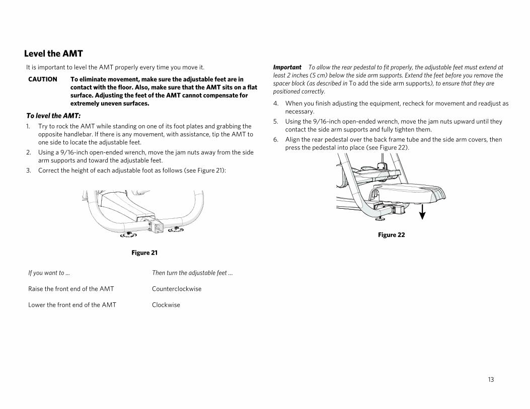
Level the AMT It is important to level the AMT properly every time you move it.
CAUTION To eliminate movement, make sure the adjustable feet are in contact with the floor. Also, make sure that the AMT sits on a flat surface. Adjusting the feet of the AMT cannot compensate for extremely uneven surfaces.
To level the AMT: 1. Try to rock the AMT while standing on one of its foot plates and grabbing the
opposite handlebar. If there is any movement, with assistance, tip the AMT to one side to locate the adjustable feet.
2. Using a 9/16-inch open-ended wrench, move the jam nuts away from the side arm supports and toward the adjustable feet.
3. Correct the height of each adjustable foot as follows (see Figure 21):
Figure 21
If you want to ... Then turn the adjustable feet …
Raise the front end of the AMT Counterclockwise
Lower the front end of the AMT Clockwise
Important To allow the rear pedestal to fit properly, the adjustable feet must extend at least 2 inches (5 cm) below the side arm supports. Extend the feet before you remove the spacer block (as described in To add the side arm supports), to ensure that they are positioned correctly.
4. When you finish adjusting the equipment, recheck for movement and readjust as necessary.
5. Using the 9/16-inch open-ended wrench, move the jam nuts upward until they contact the side arm supports and fully tighten them.
6. Align the rear pedestal over the back frame tube and the side arm covers, then press the pedestal into place (see Figure 22).
Figure 22

14

15

AMT Assembly Guide | P/N 304438-101 rev B, ENU ©2016 Precor Incorporated | October 2016

Cardio Equipment Quick Reference
Maintenance Guide
English Français Deutsch 日本語 中文
Español latinoamericano Português brasileiro

Cardio Equipment Quick Reference Maintenance Guide For complete maintenance and cleaning information, visit us at www.precor.com. For torque settings, review the product Assembly Guide included with your equipment, or go to www.precor.com for more information.
Important The owner is responsible for maintaining Precor equipment in their facility based on the recommendations below and any accompanying material.
Weekly Maintenance Tasks Cleaning procedures
Use a lint-free cloth dampened with water or an approved cleaner in the procedures below.
• Clean the floor under the equipment. DO NOT lift and hold equipment while vacuuming. When the floor is completely dry, restore power and return theequipment to its level position.
• Clean all surfaces of the frame and plastic components. Keep excess moisture away from electronic components to prevent electrical shock or damage, anddry completely.
• Use a soft nylon scrub brush to clean grooves and textured surfaces on foot contact locations.• On LCD- or PVS- equipped equipment, clean the screen using only a diluted solution of one part 91% isopropyl alcohol to one part water on a damped, lint-free cloth.
Dry completely.• For elliptical and treadmill only Clean debris from all wheels (for treadmill and elliptical) and CrossRamp® (for elliptical). Dry completely.
Other weekly maintenance tasks for all equipment • Unplug the power cords from any equipment or entertainment devices plugged into a wall outlet. For treadmill: Turn off the circuit breaker.• Verify all equipment feet sit squarely on the floor, and adjust if necessary to ensure the equipment does not wobble.• Verify that the power cords are not damaged or pinched.• Plug in the equipment, turn it on, and verify the following features are performing properly:
Handheld Heart Rate (HHHR) Incline, Speed, and Resistance controls
• Elliptical only Elevate the equipment to its maximum incline. Clean the ramp (no disassembly required). Debris build-up will shorten the life of the product.
• Treadmill only Verify the safety lanyard works. Emergency Stop Button Elevate the equipment to its maximum incline. Follow the procedures, Check the alignment of the running belt and Adjust the running belt, in this Guide.
4

Monthly Maintenance Tasks Perform all checks listed under Weekly Maintenance Tasks plus the following:
For all equipment • Verify the Wireless Heart Rate feature is performing properly by following the procedure, Verify that the heart rate feature works, in this Guide.• Remove plastic enclosures from the drive compartments and remove any lint or debris, and then do the following in order:
Clean the drive belts and pulleys with a small wire brush. Vacuum out any debris, being careful not to bring the vacuum cleaner nozzle too close to any circuit board. Precor recommends you use a vacuum that protects
against static buildup. Inspect visible welds, frame, and wire connections. Check all fasteners for proper tightness and torque. Treadmill, elliptical, and AMT only Clean and lubricate the lift motor screw with an approved grease such as SuperLube® with Teflon or Mobil 1™ synthetic
grease, if necessary. Treadmill only Verify the power cord clamp is securely installed. Replace all removed plastic enclosures.
• Treadmill only Visually inspect the running deck and belt. Make sure the deck and belt are in good condition and replace the belt, if necessary.• Elliptical only
Verify that the wheels run smoothly on the CrossRamp®. Check all wheels for wear or cracks. Lift the badge plate from the bottom front to loosen the rubber gasket. Remove the gasket (at the split) from the back of the display mount. Clean debris then
replace the gasket from back to front, aligning the tabs as you go.DO NOT pull the gasket ring off before removing the badge plate first.
• AMT and climber only Inspect support belts and pulleys for wear or damage. Check torque on belt clamps.• All equipment except treadmill Verify pedals move smoothly and freely in all directions.• Bikes only Verify that the seat moves through the entire adjustment range and that the position latch works correctly.• For treadmill only Clean the underside of the running belt and top deck by following the procedure, Clean the running belt and deck in this Guide or visit us at
www.precor.com.
5

Quarterly Maintenance Tasks Perform all checks listed under Weekly Maintenance Tasks and Monthly Maintenance Tasks, plus the following:
• Check tension of the running belts and adjust if necessary. Inspect belts for excessive wear.• Perform software diagnostics and check LED function.• AMT only Inspect the gas spring shock. Contact Precor Customer Support if you have questions.• EFX only Check the belt tension.• Bikes only Verify that the seat is secure and stable.• Climber only Inspect the tension springs and pedal stops for damage and function.
Semi-Annual Tasks • All equipment except treadmill Verify battery voltage.• Treadmill only Lubricate the lift motor screw.
6

Error Codes The following is a list of error codes and how to resolve the issue:
Error Codes Action Equipment
00-09, 11-16, 50 Turn the equipment off and on. Repeat twice. If the message still appears, contact a Precor certified service technician. AMT, elliptical, treadmill, RBK, UBK, and CLM
10, 20-23, 26-28, 32, LS, ERR, E2, E4 Contact a Precor-certified service technician. AMT, elliptical, treadmill, RBK, UBK, and CLM
40, 42, 44-46 Logs error and displays code to user. User can continue the workout without interruption. AMT, elliptical, treadmill, RBK, UBK, and CLM
80-83 Turn the equipment off and on. Repeat twice. If the message still appears, contact a Precor certified service technician. AMT, elliptical, treadmill, RBK, UBK, and CLM
30, 31 Displays the error on the console to the user. Restart the equipment or reset the E-STOP to use. Logs as a fatal error. AMT, elliptical, treadmill, RBK, UBK, and CLM
62, 70-77 Contact a Precor certified service technician. AMT only
78 Display the message, "Belts must be changed soon", in place of the standard banner text. Logs the error and allows the user to begin the workout. Contact a Precor certified service technician. AMT only
79 Displays the message, "Belts change required", in place of the standard banner text. No workout can be started. Contact a Precor-certified service technician. AMT only
17-20, 25, 85-88 Turn the equipment off and on. Repeat twice. If the message still appears, contact a Precor certified service technician. treadmill only
29 Displays the error on the console to the user and pauses the workout. The treadmill speed MUST return to 0 before starting again. Logs the error. treadmill only
33, 35-37, 60, 62 Displays the error on the console to the user. Restart the equipment or reset the E-STOP to use. Logs as a fatal error. treadmill only
7

Verify that the heart rate display works To verify that the heart rate display is operational: 1. Begin exercising on the equipment and grasp both touch-sensitive handlebars. The heart icon flashes while the heart rate is read. You must maintain contact with both
metal plates on each handlebar to ensure an accurate reading.2. Within ten seconds, your heart rate number appears in the HEART RATE display. If a number does not appear, perform the following checks:
Verify that the HR cable is properly connected. Repeat the test with a different person. In rare instances, it may not work properly for a few individuals. Repeat this test using a chest strap or a wireless pulse simulator. You’ll get better results than if you only grasp the touch-sensitive handlebars. DO NOT hold
onto the handlebars during the reading or you’ll override those results.
Moving the equipment The equipment is very heavy. If you plan to move it to a new location, obtain the help of an adult assistant and use proper lifting techniques. If the equipment includes roller wheels on one end, use the wheels to reduce the load on yourself and your assistant.
To move the elliptical (EFX): • Precor recommends using a four-wheeled dolly to move the EFX.
To move the AMT: 1. Disconnect, unplug, and remove all external connections (television, Ethernet, and power).2. Lift the rear platform molding to remove it.3. Lift the rear foot supports to tip the AMT forward onto its roller wheels.4. Push the AMT into its new location.5. Lower the rear foot supports to the floor, then reattach the rear platform molding.
To move the treadmill:
A treadmill in an inclined position is easier to move.
Important The plastic end caps on Precor treadmills are designed specifically for lifting. Working with your assistant, place a hand under each side of the end cap. Then, using proper lifting techniques, lift the rear of the treadmill so that it rolls on its front wheels.
8

To put the treadmill into an inclined position for moving: 1. Press GO on the console.2. Increase the incline to Level 4 or more.3. While the treadmill is running, turn the main power switch to OFF.4. Disconnect the treadmill’s power cord.
Check the alignment of the running belt (treadmill only) Important Failure to align the belt may cause the belt to tear or fray, which is not covered by the Precor Limited Warranty.
Proper alignment allows the belt to remain centered and ensures smooth operation. Realigning the belt takes a few simple adjustments. If you are unsure about this procedure, contact Precor Customer Support.
CAUTION DO NOT adjust the running belt when someone is standing on it.
To check the alignment of the running belt: 1. Make sure that the running surface is as level as possible. If necessary, adjust the rear feet to level the treadmill.
Note Adjusting the rear feet cannot compensate for extremely uneven surfaces. If you cannot make the running surface level and stable, move the treadmill.
2. Turn the treadmill on.3. Stand beside the treadmill (not on it), and press GO or QuickStart on the console.4. If necessary, enter the safety code by pressing the number keys in sequence. The running belt starts automatically after a 3-second countdown appears on the console.5. Press SPEED UP until the console shows a speed of 3 mph (5 kph).6. Observe the belt from the rear of the treadmill for a few minutes. The belt should remain centered along the running bed. If it drifts off center, you need to adjustment it.
CAUTION If you hear any rubbing or the running belt appears damaged, press the red STOP button immediately and contact Precor Customer Support.
7. Press STOP to stop the belt and turn the treadmill off.
9

Adjust the running belt (treadmill only) If you are unsure about adjusting the running belt, contact Precor Customer Support.
CAUTION Take special care when aligning the running belt. The treadmill will not stop immediately if an object becomes caught in the belt or rollers. Turn OFF the treadmill while adjusting or working near the rear roller. DO NOT wear loose clothing or allow your hair to hang loose during this procedure. DO NOT adjust the running belt when someone is standing on it. Keep your fingers and any other object clear of the belt and rollers, especially in front of the roller and behind the deck.
Important Make all belt adjustments on the adjusting bolts at the rear corners of the treadmill using the hex key provided, and DO NOT turn either bolt more than ¼ turn before checking the alignment of the running belt again. Overtightening the adjusting bolts can damage the treadmill.
To adjust the running belt:
1. Locate the adjusting bolt in the right side end cap at the rear corner of the treadmill(Figure 1).
Figure 1
2. Use the hex key to tighten the adjusting bolt in the direction that the belt is shifting.Turn the bolt ¼ turn clockwise.If the belt ... Then ...
Continues to shift in the original direction
Turn the same adjusting bolt an additional ¼ turn clockwise.
Starts to shift in the opposite direction
Turn the same adjusting bolt ⅛ turn or less counterclockwise.
3. Recheck the belt position as described in Check the Alignment of the running belt.
Note If the belt slips after you have adjusted it, tighten the adjusting bolt evenly, ¼ turn at a time, until the slipping stops. DO NOT overtighten the belt.
10
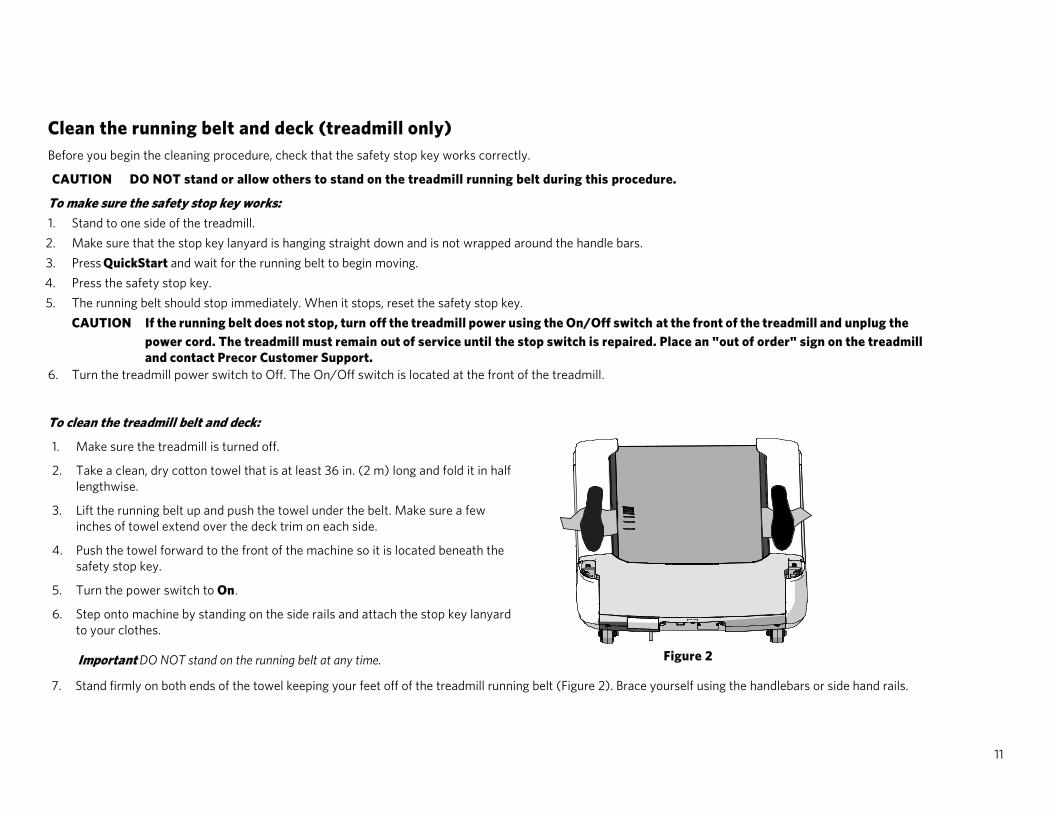
Clean the running belt and deck (treadmill only) Before you begin the cleaning procedure, check that the safety stop key works correctly.
CAUTION DO NOT stand or allow others to stand on the treadmill running belt during this procedure.
To make sure the safety stop key works: 1. Stand to one side of the treadmill.2. Make sure that the stop key lanyard is hanging straight down and is not wrapped around the handle bars.3. Press QuickStart and wait for the running belt to begin moving.4. Press the safety stop key.5. The running belt should stop immediately. When it stops, reset the safety stop key.
CAUTION If the running belt does not stop, turn off the treadmill power using the On/Off switch at the front of the treadmill and unplug the power cord. The treadmill must remain out of service until the stop switch is repaired. Place an "out of order" sign on the treadmill and contact Precor Customer Support.
6. Turn the treadmill power switch to Off. The On/Off switch is located at the front of the treadmill.
To clean the treadmill belt and deck:
1. Make sure the treadmill is turned off.
Figure 2
2. Take a clean, dry cotton towel that is at least 36 in. (2 m) long and fold it in halflengthwise.
3. Lift the running belt up and push the towel under the belt. Make sure a fewinches of towel extend over the deck trim on each side.
4. Push the towel forward to the front of the machine so it is located beneath thesafety stop key.
5. Turn the power switch to On.
6. Step onto machine by standing on the side rails and attach the stop key lanyardto your clothes.
Important DO NOT stand on the running belt at any time.
7. Stand firmly on both ends of the towel keeping your feet off of the treadmill running belt (Figure 2). Brace yourself using the handlebars or side hand rails.
11

8. Press Quick Start.Important You have three seconds before the treadmill belt begins to move. Hold the handlebars or side hand rails to help maintain balance.
9. The treadmill will run at 1 mph. Allow the treadmill to run for one minute while keeping the towel firmly in place.
CAUTION Press the safety stop key if the towel becomes loose to prevent it from being pulled into the treadmill’s rollers.DO NOT adjust the treadmill’s speed or run it higher than 1 mph.
10. After one minute, press Stop to stop the treadmill belt.
11. When the belt is completely stopped, remove the stop key lanyard from your clothing, and step off the treadmill.
12. Turn the treadmill power switch to Off.
13. Grasp both sides of the towel and run it up and down the length of the belt several times to clean the top of the deck before removing it from beneath the belt.
14. Turn the power switch to On and return the treadmill to normal use.
Maintenance Guide | P/N 305034-101 rev A, ENU ©2016 Precor Incorporated | April 2016 12

日本語
中文


日本語
中文