Embed Size (px)
Citation preview
r j
AD-A012 898
THIOVEC(R) TVC NOZZLE WARM GAS ACTUATION
j Conrad R. Huskey
Thiokol Corporation
1
1 K '
Prepared for:
Naval Surface Weapons Center
30 June 1975
DISTRIBUTED BY:
Um InfimitiM Strvict
U. S. DEPARTMENT OF COMMERCE

219106
*
00
00 THIOKOL CORPORATION
ELKTON DIVISION ELKTON, MARYLAND
E125-75
FINAL PROGRAM SUMMARY REPORT
1HIOVECw TVC NOZZLE WARM GAS ACTUATION CONTRACT N60921-74-C-0318
TTT-- PREPARED FOR:
NAVAL SURFACE WEAPONS CENTER WHITE OAK LABORATORY
SILVER SPRING, MARYLAND 20910
PREPARED BY:
MR. CONRAD HUSKEY SENIOR PROJECT ENGINEER
JUNE 30, 1975
kvproduird by
NATIONAL TECHNICAL INFORMATION SERVICE
U 5 Deportment of Commerce Spring4»«! VA 22151
/ ~\ i n c T\\
'•
• '".•• *._
Disirffcullc;; o.J:.-..i..-"J
59«

p» *
Unclassified Security Classification
DOCUMENT CONTROL DATA -R&D (Steurlly claoMilicatlon of tltla, body of ammtmcl and Indafjnj wwcWUon mvit km mntatod wnon Iho mvrmU wort It claaalllaS)
I. OmaiMATIN« ACTIVITY (C to author)
Thiokol Corporation Elkton Division, Elkton, Maryland 21921
»•.MKPOftT SBCUWITV CLASSIFICATION
Unclassified t*. CPOUP
S. RKPOftT TITL«
FINAL PROGRAM SUMMARY REPORT: THIOVEC® TVC NOZZLE WARM GAS ACTUATION
*• EA»CRJPTI v« NOTES (Tyno otropowt and tnchmlra dato»)
" AUTHORts» (Flntnama. atltnUa Initial, loot romp}
Conrad R. Huskey, Senior Project Engineer
•• a«POUT OATS June 30, 1975
aa. CON- N60921-74-C-Ö31S
S.SROJCCTNO. -1529
ta. oisTniauTiON STATCMKMT
9a. TOT*' MO. OF PACKS *A°
76. NO. OF WSrt
aa. cmaiNATOR*S RBPORT NUMSKRIS»
E125-75
aa. oTMss REPORT NOW (Atay maammatQ
Oswl#a AWWvfff sn#f BSV •>• A00f^1#V
II- sui
IS. ABSTRACT
IS. SP >NSORINC MILITARY ACTIVITY ^ü
:wj
Naval Surface Weapons Center White Oak Laboratory Silver Spring. Maryland 20910
Warm gas actuation of a THIOVEC® TVC nozzle was demonstrated using a solid propellant gas generator and a solenoid operated bi-stable flapper-type warm gas valve. The TVC nozzle's dynamic characteristics were obtained in a series of bench tests with simulated motor chamber pressure producing the resistive torques normally experienced under motor operating conditions. These bench tests provided frequency response, phase lag, slew rate, and system hysteresis data which proved the system to be a viable candidate for low- maintenance, cost-effective TVC nozzle system applications.
te DMflsj 1 A "W<* M»i««aa oo roaas tat*, i JAM a«.
taw* «14 73 osaxtTiFea.aaruM. SMfCM IS •iiyi&i «MB
UcAty ftaaaincattoa
---
Scorify CiM«iflc»ttot» 14.
KIY WORD!
actuation pneumatic TVC nozzle
Ifr
LINK A
ROLt WT
LINK • LINK C
ROLI ROLI
Unclassified Security Clattlflcation

P.O. Box 241, Elkton. Maryland 21921 301/398-3000
'/• ELKTON DIVISION
In Reply Refer To: E125-75 June 30, 1975
Naval Surface Weapons Center White Oak Laboratory Silver Spring, Maryland 20910
Attention: Mr. Eugene Eiztfon, WR-12
Subject: Final Program Summary Report; THIOVEC^TVC Nozzle Warm Gas Actuation
Reference: Contract N60921-74-C-0318
Gentlemen:
We are pleased to submit this final program summary report marking the conclusion of a successful Warm Gas Actuation demonstration program of the THIOVEC®TVC nozzle.
The enclosed report contains summaries of the nozzle calibration and Warm Gas Actuation tests which have verified the elimination of hydraulics from a thrust vector control nozzle as practical.
If you have any questions concerning this report, please contact either Joseph Reardon, Program Manager, or F. I. Ochs, Manager, Contracts Administration.
Very truly yours,
THIOKOL CORPORATION ELKTON DIVISION
JER/cm
7. M. Davis General Manager
Ou^
/* A DIVISION OF THIOKOL CORPORATION
E125-75 June 30, 1975
cc: Naval Surface Weapons Center Silver Spring, Maryland 20910
Attention: Code WR-12 (M. Stosz, R. Bardos - 1 copy each) Code WX-21 (1 copy) Code WU-06 (P. Fineran - 1 copy)
Naval Sea Systems Command Washington, D. C. 20360
Attention: Code 0331 (J. Murrin, M. Murphy - 1 copy each) Code 654311B (D. Olsen - 1 copy)
Naval Weapons Center China Lake, California 93555
Attention: Code 457 (R. Feist - 1 copy) Code 4574 (S. Benson, 1 copy)
Chemical Propulsion Information Agency Mailing List
Defense Documentation Center Cameron Station Arlington, Virginia 22314 (12 copies)
>t<

E125-75
THIOKOL CORPORATION ELKTON DIVISION
ELKTON, MARYLAND
FINAL PROGRAM SUMMARY REPORT
iOVEC® TVC NOZZLE WARM GAS ACTUATION CONTRACT N60921-74-C-0318
PREPARED FOR:
NAVAL SURFACE WEAPONS CENTER WHITE OAK LABORATORY
SILVER SPRING, MARYLAND 20910
PREPARED BY:
MR. CONRAD HUSKEY SENIOR PROJECT ENGINEER
JUNE 30, 1975
APPROVED BY:
JU. <^~- T. M. Davis
General Manager
i<
E125-75
FOREWORD
This Final Report of the THIOVEC®TVC Nozzle Warm Gas Actuation program is submitted to the Naval Surface Weapons Center, White Oak Laboratory, Silver Spring, Maryland, in accordance with the requirements of Contract N60921-74-C- 0318.
The following Thiokol personnel contributed to this program:
Conrad Huskey Senior Project Engineer Richard Bourdon Design Engineer Carl Gonce Test Engineer Joseph Reardon Program Manager
Mr. Conrad Huskey was responsible for the technical direction of the program and was the author of this Final Report. Mr. Eugene Elzufon of the Naval Surface Weapons Center was responsible for the technical coordination and monitoring of this Navy-sponsored program.
»•
A
E125-75
TABLE OF CONTENTS
Page
1.0 INTRODUCTION * 1
2.0 PROGRAM OBJECTIVES 2
3.0 DISCUSSION 3
3.1 General 3 3.2 Warm Gas Actuation System 3 3.3 Description of Tests 6
4.0 TEST RESULTS 16
4.1 General 16 4.2 Duty Cycle Tests 16 4.3 Command Input Versus Nozzle Position 20 4.4 Frequency Response and Phase Lags 20
5.0 NOZZLE POST-TEST HARDWARE CONDITION 28
6.0 CONCLUSIONS 38
APPENDIX A, Nozzle Description
ii
E125-75
LIST OF ILLUSTRATIONS
PAGE
1. Pneumatic Control - THIOVEC® TVC 4 2. Nozzle Command Duty Cycle 8 3. Test Arrangement 8 4. Nozzle Assembly, Drawing No. E28478 10 5. Nozzle Assembly, Test Arrangement 11 6. Gas-Test Arrangement, Drawing E27647 12 7. Nozzle Test Arrangment 13 8. Duty Cycle Test Results 17 9. Duty Cycle, Chamber and Vector Set.i Pressure 18
10. Duty Cycle Test, Chamber and Vector Seal Pressure 19 11. Hysteresis Loop Test Result 21 12. Hysteresis Test, Chamber and Vector Seal Pressure 22 13. Hysteresis Test, Chamber and Vector Seal Pressure 23 14. Frequency Response, Test Results 24 15. Frequency Response Test, Chamber and Vector Seal Pressure 25 18. Frequency Response Test, Chamber and Vector Seal Pressure 26 17. Nozzle Frequency Response 27 18. Post-Test Vector Seal Assembly No. 1 29 19. Post-Test Vector Seal Assembly No. 2 30 20. Vector Seal Cover, Post-Test, Seal No. 1 31 21. Vector Seal Cover, Post-Test, Seal No. 2 32 22. Vector Seal Components, Post-Test 33 23. Outer Race, Post-Test 34
iii
E125-75
1.0 INTRODUCTION
A two-phase program was conducted to demonstrate warm gas actuation of the THIOVEC TV C nozzle system. The culmination of the effort was warm gas actuation bench tests which demonstrated fieasibility in Phase I and characterized nozzle performance in Phase II. During the tests, the THIOVEC®TVC nozzle was subjected to simulated chamber pressure, duty cycle, and operating time similar to that which may be experienced aboard a typical underwater missile. The nozzle used was re- furbished from the THIOVEC underwater static test performed under Navy Contract Number N00123-73-C-2925,
Phase I was initiated with the design of the warm gas actuation system, pro- curement of the warm gas servocontrol valve, and manufacture of the warm gas generator. Upon completion of the system design, the remaining components, such as tubing orifices and fixtures, were fabricated. After assembly of the system, nitrogen gas was used for system check-out prior to the warm gas feasibility demon- stration test. Phase I was concluded with the successful warm gas actuation test wherein all test objectives were met and performance exceeded that required. The average nozzle slew rate was 210 deg/sec from null to 90% of full deflection in response to a step command to full nozzle deflection. The nozzle's 90' phase lag and -3 db response point, determined using cold gas, occurred at 20 to 25 Hz.
Characterization of the warm gas actuation system, accomplished in Phase II, provided maximum and average slew rates, phase lag, response, and nozzle hysteresis data. The maximum slew rate was 300 deg/sec and the average was 165 deg/sec. The 90° phase lag occurred at 20 Hz and the -3 db response was at 25 Hz. The hysteresis in the system was measured at ±• 0.2 deg over full range of deflection.
/•
E125-75
2.0 PROGRAM OBJECTIVES
Both the Navy and Thiokol are interested in achieving a low cost, minimum maintenance TVC nozzle system for use in underwater missiles. Studies have shown that the THIOVEC ® TVC nozzle is low in cost relative to the other TVC nozzles, and underwater bench tests and an underwater static test have demonstrated the feasibility of that TVC system for use in underwater missiles.
The program objective is to further demonstrate features which permit the realization of low cost TVC systems. Specifically, the feasibility of warm gas actuation of the THIOVEC nozzle was to be demonstrated. The warm gas actuation system minimizes maintenance since pre launch check-out is not required because the possibility of hydraulic fluid leaks is absent. Of importance in system cost effectiveness studies is the fact that such a warm gas actuation system permits launching from sites which are inaccessible for the purpose of performing the mechani- cal prelaunch check-out ordinarily required when hydraulic actuation is used.
-2-

E125-75
3.0 DISCUSSION
3.1 General
Work in Phase I was directed toward the verification of test hardware, which W\B a necessary first step before characterization of the pneumatic actuation system in Phase II. Electrical and mechanical hardware was involved in building the pneu- matically actuated TVC nozzle system. Mechanical hardware included: 1) an existing THIOVEC® TVC nozzle; 2) a bi-stable warm gas ssrvocontrol valve which is a modification of an existing production valve; and 3) a standard test weight warm gas generator. The electrical equipment included an electronic servovalve controller, the command signal electronics, and the standard test data acquisition equipment to measure and record the pressures, temperatures, and nozzle dynamic characteristics of interest. Phase I, therefore, included all work necessary to design, fabricate, and test the TVC system through the first warm gas actuation system demonstration test. Work ia Phase II was directed toward characterizing the dynamic response of the THIOVEC TVC nozzle using a warm gas actuation system. A total of six warm gas tests were conducted in this program: one in Phase I and five in Phase II. The first two tests in Phase II were required to clear an instrumentation problem prior to initiating characterization tests. A brief description of the THIOVEC® nozzle is presented in Appendix A.
3.2 Warm Gas Actuation System
A schematic show' 4 the test arrangement, designed for single plane motion, is presented in Figure 1. OmniaxiaJ motion can be achieved using an additional control valve, two additional restrictors, and tubing to operate the vector eals in the other pis ne of motion 90° to those shown. The warm gas generator is a standard test vehicle in use at the Elkton Division of Thiokol and is designated TC-1. The propellant grain is an end-burning type 3.75 inches in diameter and 2 inches long. Since this standard grain is larger than that required for supplying the actuation gas, a secondary flow orifice was installed in the gas generator to bleed off the excess gas supply. The Thiokol-developed propellant, TP-Q-3100, is a low flame temperature (1740°F) propellant whose combustion products are free of significant particulate matter and toxic or corrosive chemical species. The Flow Restrictors permit pressurization of one vector seal actuator while sufficiently restricting flow from the generator into the venting side so as to produce the pressure differential necessary to vector the nozzle. The warm gas servocontrol valve is a bi-stable flapper type proportionally controlled with a pulse modulated command signal. The THIOVEC® nozzle is the same as that used in the previously mentioned underwater static test. To permit an economical test program, brackets were attached to this omniaxial nozzle so that it vectors in one plane only. This reduced the required number of pneumatic control valves from two to one per test and also reduced test setup time.
-3-

• H
ü
» P
'
I
Rn
pip
•• •B
^w
«
ii
i .
I.IH
P
SA27
92A
i t
Seco
ndar
y Fl
o*-
Ori
fice
TC
-1 W
arm
Gas
G
ener
ator
Igni
ter Flo
w R
est r
iet o
r
Ele
ctro
nic
Con
trol
ler
4
Feed
-Bac
k Si
gnal
Com
man
d si
gnal
C
omm
and
Ele
ctro
nics
Posi
tion
Tra
nsdu
cer
®
TH
IOV
EC
T
VC
Noz
zle
©
C)
•4)
L W
arm
Gas
Se
rvoc
ontr
ol V
alve
FIG
UR
E 1
.
PN
EU
MA
TIC
CO
NT
RO
L—
TH
IOV
EC
®T
VC N
OZ
ZL
E
TE
ST A
RR
AN
GE
ME
NT F
OR S
ING
LE A
XIS
MO
TIO
N

E125-75
Cold gas tests were conducted prior to each warm gas test to assure proper functioning of the TVC nozzle and control electronics. The cold gas, N2, was introduced into the system through the gas generator chamber, without the solid propellant grain installed. For warm gas testing, the N2 line was disconnected from the gas generator chamber and the propellant grain and igniter installed; the TVC system was then ready for the warm gas test.
Deftign calculations for the warm gas actuation system were conducted using the following assumptions:
1) Sizing of the system would permit a maximum gas generator pressure of 2000 psia under conditions of flow through the secondary orifice and one restrictor; the other restrictor was assumed closed by the valve flapper's being held in the hard-over position long enough for the gas generator to respond to the change in nozzle flow area.
2) Maximum pressure differential across opposing vector seals was assumed to be 1000 psid.
3) The actuation system was sized to provide a maximum nozzle slew rate of 200 deg/sec at an assumed gas stagnation temperature in the vector seals of 660°R.
4) It was assumed that, at the time maximum flow rate through the restrictors occurred, the down stream pressure was low enough to permit sonic flow through the restrictors.
Maximum change in vector seal volume of 0.343 in. occurs when the nozzle travels from the fully deflected position of 10 degrees vector angle to the null position. To achieve the maximum slew rate of 200 deg/sec, the volumetric rate of flow into the vector seal causing that deflection must be 6.86 in. 3/sec. Using the thermo- chemical properties of the gas generator propellant and the maximum chamber pressure, the maximum weight flow rate was calculated to be 0.026 lbs/sec. Based on this maximum flow rate, the gas generator propellant grain, secondary flow orifice, and restrictor orifices were then sized.
-5-

E125-75
.".3 Description of Tests
The following is an outline summarizing the cold and warm gas testing of the THIOVEC® TVC nozzle:
1) Sizing the Warm Gas System for TC-1 Generators
a) Verify size of restrictors and secondary orifices for a 1500 psia nominal generator operating pressure and measure temperature of exhaust gas and tubing during generator operation to assure absence of excessive heating.
b) Equipment: TC-1 gas generator; stainless steel tubing and fittings; restrictors; and secondary orifice.
2) Cold Flow Tests
a) Cold Gas Control System Checkout.
i) Cold gas pressure 500 psig.
ii) Equipment: (a) servocontroller;. (b) PDM valve; (c) TC-1 gas generator without propellant or igniter; (d) restrictors and tubing to valve and nozzle.
b) Nozzle and Control System Tests.
i) Cold gas actuation system supply pressure 1500 psig.
ii) Equipment: (a) servocontroller; (b) PDM valve; (c) TC-1 gas generator without propellant or igniter; (d) tubing, restrictors, and tubing to valve and nozzle,
iii) Nozzle internal pressure at 1500 psia to simulate motor chamber pressure.
iv) Nozzle test: system gain adjusted to maximize response and to eliminate nozzle overshoot prior to data acquisition of following tests:
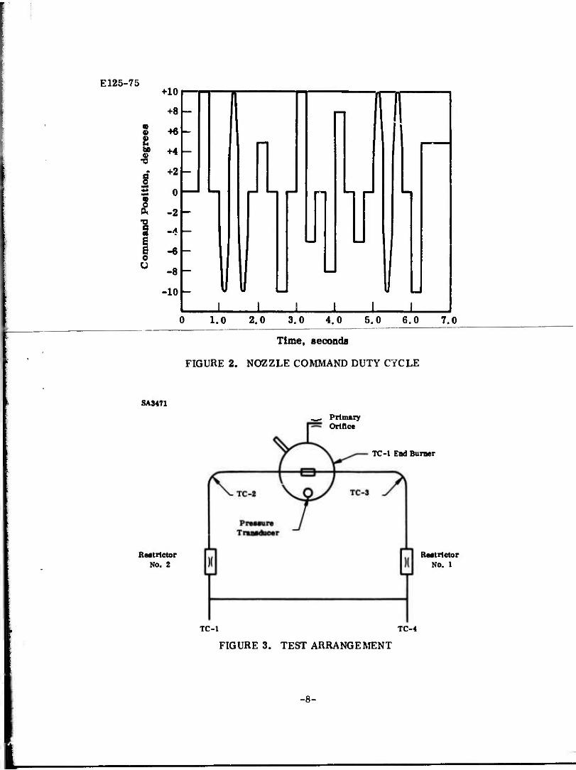
• Duty cycle (see Figure 2).
• Hysteresis loop.
• Nozzle response (-3 db point) and phase lag (90° shift point).
-6-

E125-75
3) Warm Gas Tests
a) Operating pressure of TC-1 gas generator was 1500 psia nominal.
b) Nozzle internal pressure 1500 psia simulating motor chamber pressure.
c) Equipment: same as cold gas except that a propellant grain, igniter, and primary orifice are used and the cold gas system is disconnected.
d) Tests:
i) Duty cycle (see Figure 2).
ii) Hysteresis loop.
ttt) Nozzle response (-3 db point) and phase lag (90° shift point).
The gas generator used to provide the driving force to the THIOVEC® nozzle is a standard end-burning generator designated TC-1. The propellant used was TP-Q-3100. The gas generator, which has a flow rate in excess of that required, used a secondary flow control orifice to permit bleed-off of excess gas. A test arrangement as shovn in Figure 3 was made to verify the orifice sizes. The gas generator was assembled in the same manner as that used for the nozzle actuation tests with the exception that the valve was deleted and the gas permitted to dump overboard after passing through the two restrictors. The intended operating pressure of the gas generator was to be 1500 psia, with both restrictors and the secondary orilice venting to atmosphere.
The tubing and fittings used to duct the gas from the generator were of 316-type stainless steel and were standard commercial items. The secondary and restrictor orif-'ces were made from stainless steel pipe plugs which were drilled to the proper orifice diameters. The drilled plugs could then be easily assembled as they simply threaded in place. All tubing was reused several times without damage or rework except for cleaning.
Thermocouples were placed on the outisde of the tubing and in the exhaust stream. The temperature of the tubing at TC-.' and -3 locations was approximately 1500°F. The approximate static exhaust gas temperature measured at the discharge, locations TC-1 and -4, was approximately 1100°F.
-7-
E125-75 +10
+8
•6
bß 4.4
•8
1
C Ü
+2
0
-2
-6
-8
•10
n " !
; IIM II i i i i i i
0 1.0 2.0 3.0 4.0 5.0 6.0 7.0
SA3471
Time, seconds
FIGURE 2. NOZZLE COMMAND DUTY CYCLE
. Primary Orifice
TC-1 End Burner
Reatrlctor No. 2
Reatrlctor No. 1
TC-1 TC-4
FIGURE 3. TEST ARRANGEMENT
-8-

E125-75
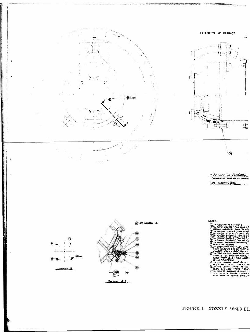
The THIOVEC nozzle assembly, shown in Figure 4 (E28478), was assembled with only two vector seals for single plane nozzle motion instead of the number required for omnial nozzle motion to simplify the test arrangement and to control electronics. A guide bar and rubbing blocks were used on the nozzle to act as a guide to limit actuation to only one plane. This successfully minimizes the cost and complexity of the nozzle tests. It should be noted that the same vector seal assemblies were used for all the test sequences, including the cold gas actuation tests, to demonstrate their compatibility with the warm gas actuation system. A photograph of the nozzle assembly is shown in Figure 5.
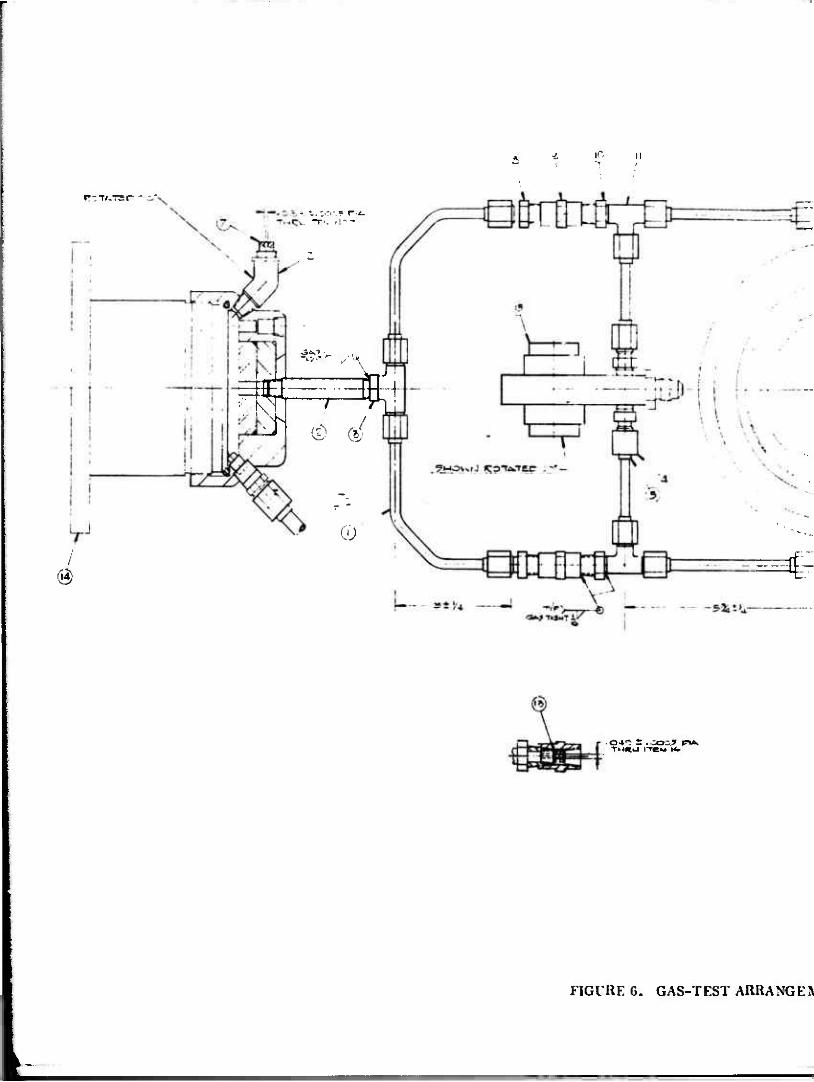
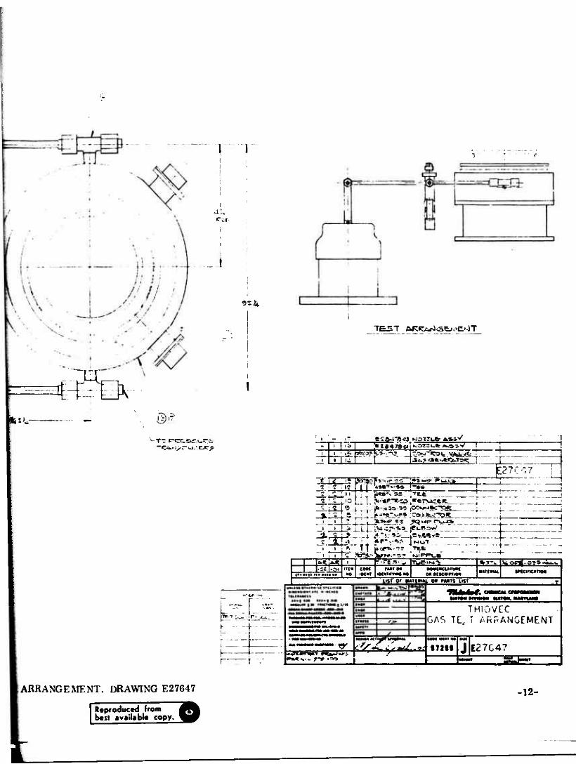
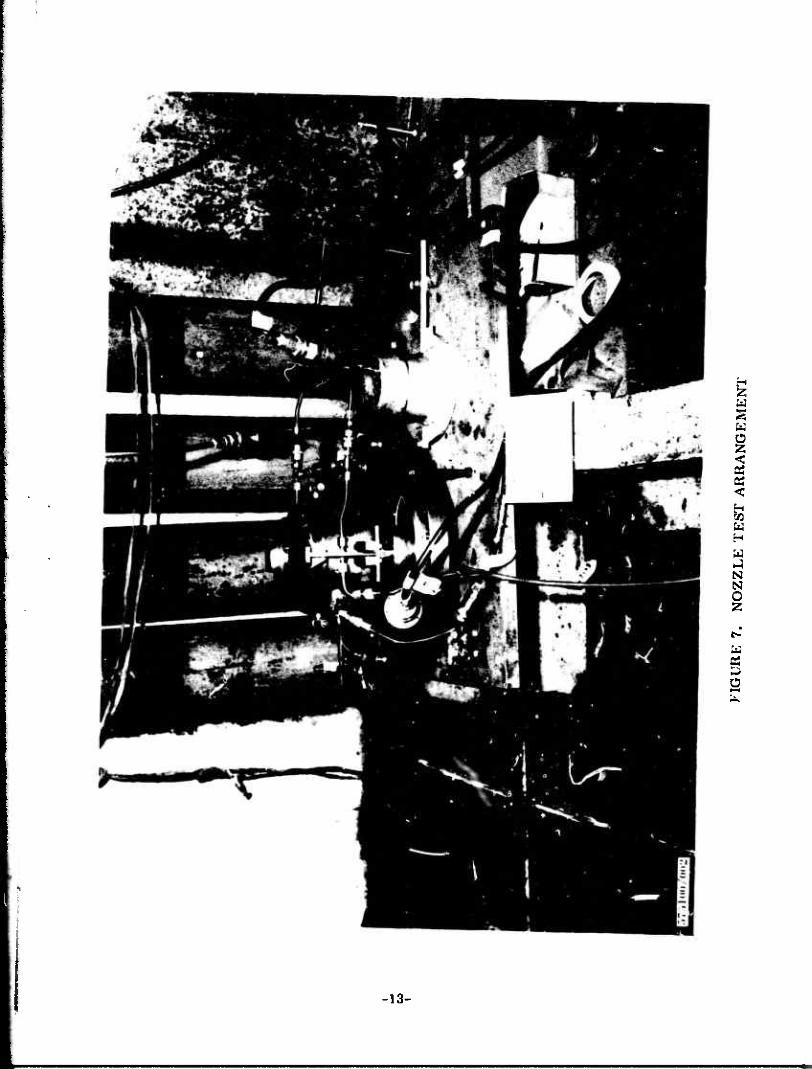
After assembly the nozzle was checked for adequate clearance by performing an internal nozzle pressure versus nozzle axial deflection test to verify that the grease bearing was assembled properly. After successfully completing the test, the nozzle was placed in a static test bay where all nozzle testing was conducted. The nozzle was attache J to thr TC-1 gas generator in accordance with drawing E27647, presented in F ure 6. A photograph of this assembly is shown in Figure 7. The primary orifice and igniter were removed, the flex lines and valves from the cold gas source (GN2 bottles) were attached, and the cold gas actuation testing of the nozzle completed. The pressure from the ON2 bottles was regulated to achieve 1500 psia inside the TC-1 pressure chamber. The test setup was identical for both Phase I and Phase n program.
The arrangements for the cold gas tests were the same as those for the warm gas tests except that the primary orifice, igniter, and propellant grain were not used. The gas exited through a vertical pipe and was directed by means of a tee to two 1/4 inch O.D. tainless steel tubes. Two 0.049 inch diameter restrictors were installed in the line between the gas generator and the valve. The gas flow through each restrictor was directed to the vector seals by means of the warm gas servocontrol valve. The control valve is a bi-stable, flapper-type valve which operates in a pulse duration modulation (PDM) mode and provides proportional control to the nozzle position. It is similar to the single stage flapper valves developed at Aeronutronic Division, Philco-Ford Corporation for the Shillelagh Jet Reaction Control system, and now used for the pilot system of the two-stage Minuteman Roll Control valve which is currently in production.
The valve has a flexurally-mounted armature (flapper) within a cylindrical body which incorporates magnetic pole pieces and flow orifices. The only moving part of the control valve is the flexure-mounted flapper. The flapper is made of ferro- magnetic alloy, welded to a stainless steel flexure. The flexure suspends the flapper between two sets of magnetic pole pieces: gas enters the valve through either of the two control valve flow orifices, as selected by energizing the appropriate solenoid coil and by moving the flapper to close one of the orifices. Gas entering the valve then exhausts through the vent port.
-9-
ff • I
,.~»«<^x«TOTI^W-*TTO«*N?!•^^ •*-*"-.•. <a|W—»WM— „,
EXTENO — ~ RETRACT
V N
..
Ol*
,'\ .-* (:
^E> •• •::
A —>-vJ^ -
/.
3 : :L
13
I. —. cfc
Mg
££=*_
**'— 1
£ :ä* axpraj B
-&$ $
NOTES:
T>«^ir a*(*sto~»"<*•* *) r< 'mr**, suewcss ruce TU iss Ifc* yctQue s.ifMiS ', '** *a #.)
S>2» lOe&Jt SC*£*S .ITiM+C ly
ap-r^v^/Htr- T*euio eeußOm/c (, * ««r-afi o# sctews. 3^=» * utt/caur fl T€M AJG-I*£TO
OVM MC tso* Bf) so y»"9r tf* _rf<*<,.-« «*<VM .*«• ß+cto ^gZ=»VB*T f»7.tc SiM**cr% o*
fwius >i). macK-u* buss',•:
Tfc /*STMu«ro>/ riTs» -OS C0t4*4 30** /W -0/
«T00 **0 **» WS I T- Ji_i> -O* <.¥*/"$ **»«# #1 -<«
#«*V *»*> </« 'T»A#J / yv<«
•OCt IC oce TDT*t ClC*&*
FIGURE 4. NOZZLE ASSEMBL
\

ACT
H
•»
n r! i
A » f •
... '1
' 1
EXTEND RfcTHACT
rr:,.--^-' £>'«%
"1L
9 Jm^p4**; *; :;
T - 6-' H"v
*
* •
»'30
2.'/»
£5
» - i » •
»0/ CQNFiG fSHOWU) -S3 CQjifi ;S>
(fTS* uc •*/.-. *«•»<* mtfi*C£ :- c •?'«& /
* ' •*«<*.;.#; **-J: MtCf-ttS. sort-', >* CS-t?'tH.-i.4fl.. %tl70*/*. t*J /* - ••'•' /vC" I* 1
f/l'tW VC !.'. :".. -/.V •A.X^-itfZ tc *****:<•'£" ** !-.j ?: -T'lc. / -*<«*
* «/£/* 7. 3C/&-. • . *' -«."V* «Vtff
>tfftuf; *7»i«a*.'-?i." *«*-.. «ffr. WMors s* «•-»< #«••#«..•*, «•* .»sjrs
JT/f* UUVi .'-"«/* , • "£^ •* ••. *»*'• 2 ? *J -; ";v
/W» »J
Hf Si KXS '?•* ••• •». "••- T**i- •'-tea ; BK Cist* •• •:«." *. '•* '• *• «•uetM; sc *>.<
'»
3»=! 2 «<•
gtotyci SJTTQH
4*4 »
;i ,"* r*",i%.u-
.'J i'" '. " l1* * ~* ' ' ".. ^,'„,
* /~J» ; 1
' -' ee' »«Jio " ' -it*. J!l*»i___ . ,"G ,»,
# f i T i X».
'Till'.!.' i« :«©••
_±oc»0 CUP sere* MMI4M *>Ttu-"0**Tn
. ItlOlhQI XCOLCtJ*.
sa-nrr
toe m> C0*sca*w ~QUTt* i*ct ___ sat» m*J5 •Q"gl>J6 7-iumt> eeumiuc . ioc »3 CUP sctif-f
J/'f-S». «Mf-«*»Lctl
"/**•*»«•«*•» *»/^ I
/*f;'f **<•»* 4** i
t**SlO-Cl SKTtVS*»,, jjfflmg
\*i*oil-*>t'iC «M4| •i—: 1 —I—
4l*T; c: ;»]<>>:„i 4 [4 I 2 2 '/• g«*»i*ro7/7 Mf«rV R^, !*£= -fj*
tHiii-a eo-nt, »ten* atn. "'• c y4 I* 'j? **«S
• iü-rin rygSI i " ' j-zfcoa-ct /vocMran **+*, nömrö
,'ercti-H \sr»Lj „tc-rct.uq
• I * I * . r< IÖL _ ! sfttt^-c' sr/H. armm*4# j ##[•*. «I 4«f;* " ^uU.COuT
""i**-72-0/ <4A/«4 *»cy "" "
JKMIiLV, Iiinwixr. NO. 12-17 -10-
»I..

•'
••
m»"
.»-'
»••'
•" "
»N.i
wii
i ,_
„„
._,_
„,^
w..,„
„ . i
. J
i. i|
Wi m
BB
.Uo»
FIG
UR
E 5
. N
OZ
ZL
E A
SSE
MB
LY
, T
EST
AR
RA
NG
EM
EN
T
10 ii
p-T/.TEt—-
WF^k 3- CD d
QJ
^~
l
04^ i .cos? n*> TM«IJ ire« •<•
FIGURE G. GAS-TEST ARRANGER
! 1
a!«. Per-
914
TE^sT ARC*r4<3ej.*C'0T
*i>*- . ©.?
""^<fc' i> r* >-». -.c^r i '•2 84 78-0 K3i:i-t*^5V
Z 7 XI
1 ' z , to
h-z. \9%**r'* s=afc "P7C^7
->PJL.
2.L ö*«^** |P»»?»A?
h
h - - • -
1 1 t ••-
feSifeS :2L ' »l.M|D1'»»M NO Igt MT iBl«""»>"C »O
4s ——-
-zi UQ» "t* COM M»T on • re a • y Tuei^-b
OaMKWTTtM
LIST or NATUUL ot nwTs LIST
%-->. IWortf-OS». ancincariM
%iMTO» WgMOII HU». MJHT1A—
THIOVCC GAS TC, T ARRANGEMENT
I27C4?
ARRANGEMENT, DRAWING E27647
Reproduced from best available copy.
-12-
u w o <
<
w H W
N N O
o
-13-
E125-75
One vlave is required for each control axis. The valve operates in a PDM mode to control the pressure differential between the opposing THIOVEC® nozzle vector seals as shown in Figure 1. Gas flow to the vector seals is introduced through a restrictor in the inlet line and is vented through the control valve. The relative sizes of the valve flow orifices and restrictors are such that with the flapper held in a hard-over position, the control valve will vent all the gas entering the inlet restrictor as well as venting the actuator on that side. All of the gas coming through the other restrictor is retained so that differential pressure is obtained.
With the control valve operating in a pulse duration modulation (PDM), the flapper dwell time on each of the restrictors controls the amount of gas in the vector seals. This establishes the differential pressure between opposing vector seals, and the resulting net torque is applied to the nozzle as a function of command.
During the warm gas tests, the flapper cycled from one flow orifice to the other at a constant cyclic rate of 60 Hz. The dwell time on either restrictor was controlled from zero to 100% of the cycle period. The PDM command is expressed on a scale from -100% to +100%, where -100% represents continuous dwell on one restrictor, +100% represents continuous dwell on the other restrictor, and 0 represents a condition where the flapper dwells 50% of the time on one restrictor and 50% on the other. These commands would correspond respectively to nozzle position of hardover one way, hardover the opposite direction, and null. Intermediate positions for pro- portional control are attained with PDM commands proportional to the position desired.
The PDM signal to the valve is generated in an integrated servoamplifier. A summing amplifier is used to compare the command and feedback signals in the pitch and/or yaw axes. The command signals are input to the amplifier module as analog voltages. The feedback signal is generated by the position indicating potentiometers attached to the nozzle.
The command and feedback signals are compared in one amplifier and summed with the PDM waveform. For improved frequency response a rate compensation network was included in the summing amplifier. The valve driver energizes one valve coil when the summing amplifier output is positive and the opposite coil when the output is negative, thus generating the percent PDM command at the waveform generator frequency. Only the summing amplifier and driver circuit need be duplicated for the second control axis.
The propellant grain used for the warm gas tests was an end-burning type which burned for a nominal action time of 6 seconds at 90% of maximum pressure. The propellant's low flame temperature and combustion products, which were free of significant solid particulate and toxic or corrosive elements, proved highly compatible with the nozzle and actuation system hardware.
-14-

E125-75
Cold gas tests were conducted before the warm gas tests to assure that the TVC nozzle and control system functioned properly prior to testing with warm gas.
Test data acquisition included internal nozzle pressure simulating motor chamber pressure, nozzle actuation supply pressure, vector seal (actuator) pressure, nozzle position, nozzle command, and nozzle bearing lubrication pressure. The data was acquired both digitally and as analog.
-15-
E125-75
4.0 TEST RESULTS
4.1 General
Three types of tests were conducted using warm gas:
1) Typical duty cycle to determine general response characteristics and response to step function command (Figure 2).
2) Command input versus nozzle position at a finite frequency to determine hysteresis loop.
3) Frequency response and phase lag.
For the three final warm gas tests the nozzle was not dismantled or cleaned; all tests were completed the same day. The nozzle was checked with cold gas prior to proceeding to the next warm gas test to verify proper operation. The first two tests were conducted with a maximum generator chamber pressure of 1680 psia. The last test had the primary orifice increased to provide a slightly lower (200 psia) pressure and a longer action time to ensure sufficient actio: time to accomplish the frequency sweep.
4.2 Duty Cycle Tests
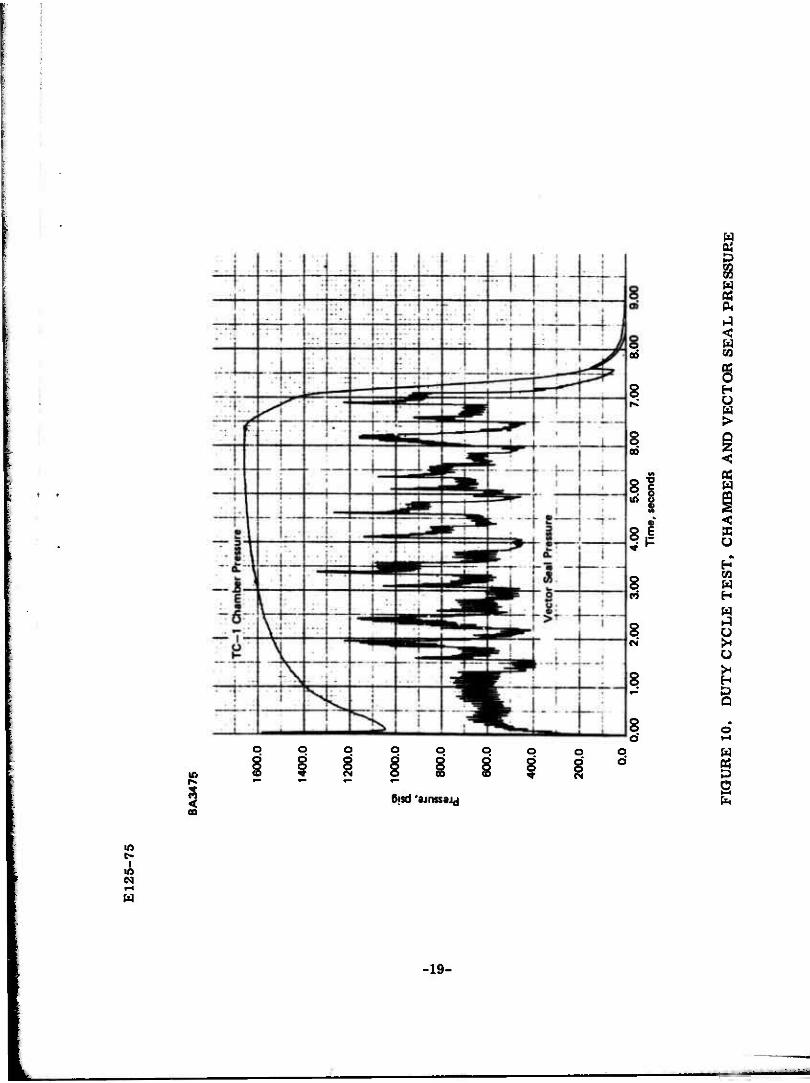
The average slew rate from time of command signal to 90% of full command deflection 10 degrees was nominally 165 deg/sec with a maximum slew rate of 297 deg/ sec. In all responses to step command there was an 0.018 to 0.020 second interval from the time of command signal to the first motion of the nozzle. No nozzle over- shoot occurred in any of the nozzle's responses to the duty cycle indicating that the nozzle had been critically damped. Figure 8 presents the test results showing the commanded duty cycle and the nozzle response. Figures 9 and 10 present the pressure- time curves of the gas generator (supply) pressure and the vector seal actuation pressures,
The maximum pressure differential across the vector seals occurred as the nozzle was reaching the commanded position. At the pre?sure spike the differential pressure was 685 psig. The spike quickly dropped off to a steady differential pressure of 420 psig. Actuation torque, developed during the pressure spike, was 1063 in.-lbs and at the more steady differential pressure condition the torque developed was 650 in.-lbs.
-16-
I I !•!

E125-75
BA3478
12.00
10.03
8.00
6.00
§> 4.00
% c o
I 2.00 o»
N
I 0.00
I -2.00
• | -4.00
-6.00
•8.00
-10.00
-12.00
j 1 1 : 1 ^_r_.j:; •-
' •
i llMf llC . i . '
i •
1 i '' i i n i I 11 i fr Ir . u»— -Hr:i--c:: i • 1 •
! * 1 I i
— ! ... .
: ' ', i ...
1 ! _j_ . „ J
— —r x.
-. J J _4 1 . j -1 ••*•"•. " T I .... ,. I
'
._.
1 H ft ! !
L .. ! I 1
II ! j
I ' i i i i . \ • -i . i
1
i -
-\ -: • - il 1 • i
• ••-- 1 • -* ! M !
1 i
I ! ' ' '.
4--i- - -]•• . j 1 1: • —
•'
--- r - " • -
'— p:
1 f B. i i • i il 1 •!
i i i
1
• 1 - ....
0.00 1.00 2.00 3.00 4.00 5.00 6.00 7.00 8.00 9.00 10.00
Time, seconds
FIGURE 8. DUTY CYCLE TEST RESULTS
-17-

E12
5-75
^fl8
P«ep»w
-«*"
'w^»
?w
«»!P
BA
3476
oo
i
1600
.0
1400
.0
1200
.0
a,
1000
.0
f 80
0.0
600.
0
400.
0
f
T_I
TC
-1 C
ham
ber
Pre
ssur
e -
i
I
,
200.
0 |
- r -
0.00
1.0
0
2.00
3.
00
4.00
5.0
0
6.
00
7
.00
8.00
9.
Ti
me,
sec
onds
FIG
UR
E 9
.
DU
TY
CY
CL
E,
CH
AM
BE
R A
ND
VE
CT
OR
SE
AL
PR
ES
SU
RE
E12
5-75
lyrm
mm
mm
rmm
vm•—
—W
PW
m m
m
u
nwy
*•«—
HM
J.fu
nij
Mi|i
Jii...
"•
"i*
WW
P .m
i" ••
• i>»
...i..
m«i
*"
j'-P
fiy.
BA
3475
I
1600
.0
1400
.0
1200
.0
.5»
100
0.0
I 80
0.0
600.
0
400.
0
200.
0
0.0
0.00
1.0
0
2.00
3.0
0
4.
00
5.00
6.
00
7
.00
8.
C T
ime,
sec
onds
FIG
UR
E 1
0.
DU
TY C
YC
LE T
ES
T,
CH
AM
BE
R A
ND V
EC
TO
R S
EA
L P
RE
SSU
RE
E125-75
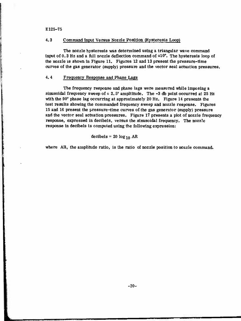
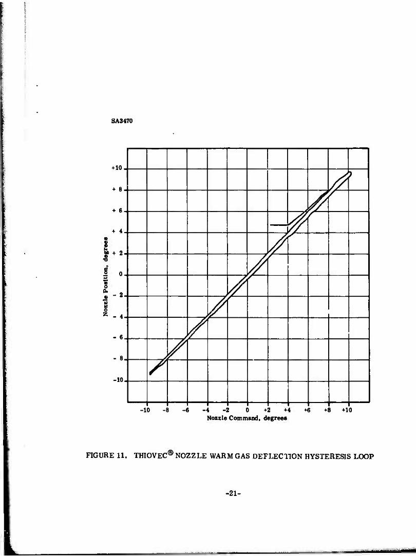
4.3 Command Input Versus Nozzle Position (Hysteresis Loop)
The nozzle hysteresis was determined using a triangular wave command input of 0.3 Hz and a full nozzle deflection command of ±10°. The hysteresis loop of the nozzle is shown in Figure 11. Figures 12 and 13 present the pressure-time curves of the gas generator (supply) pressure and the vector seal actuation pressures.
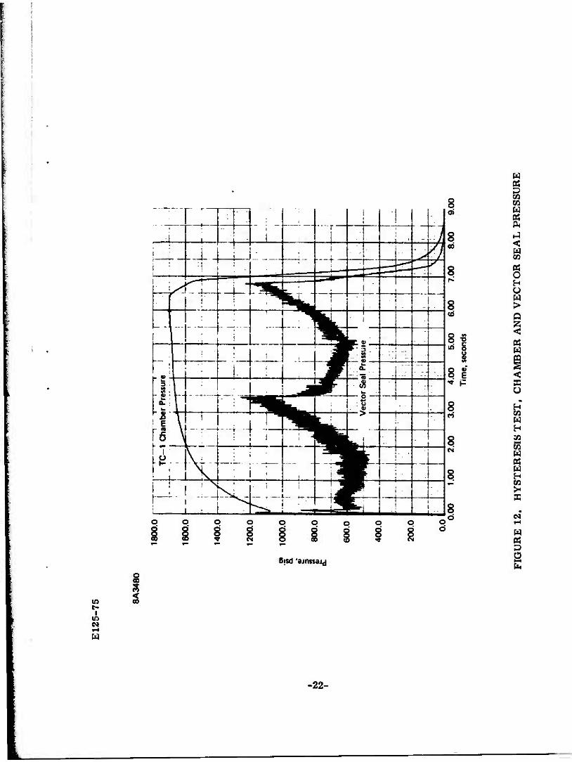
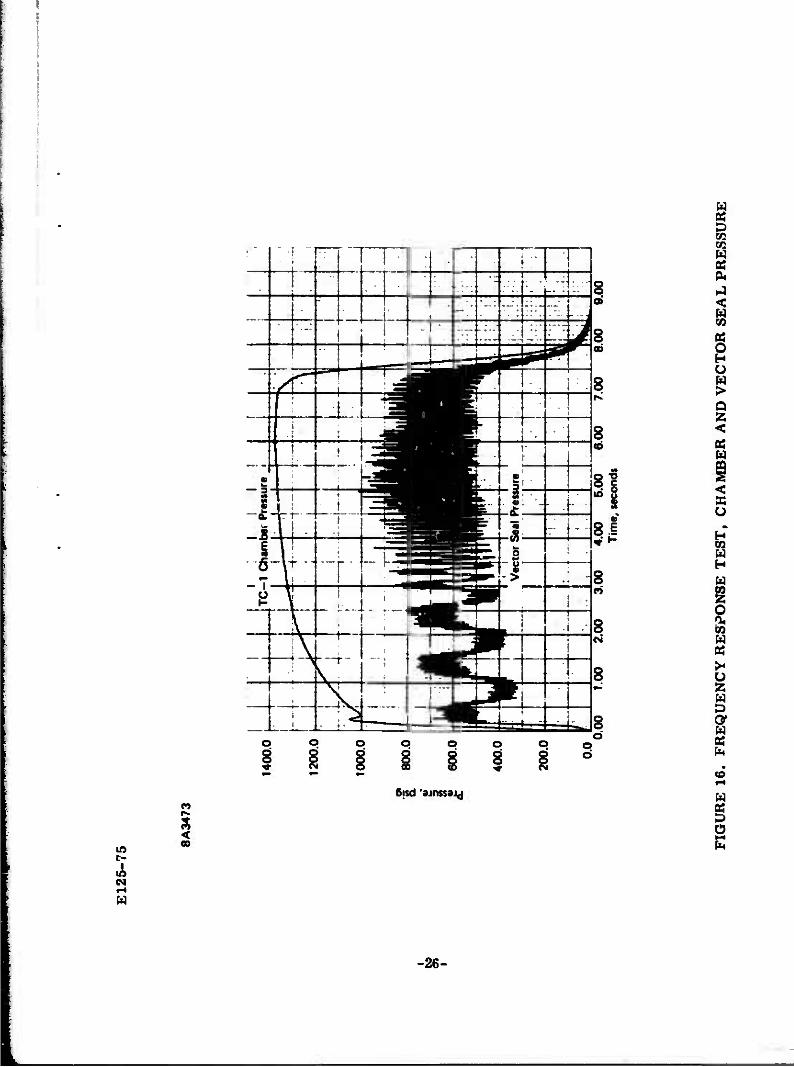
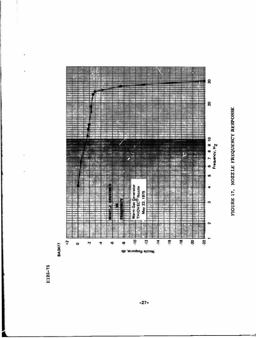
4.4 Frequency Response and Phase Lags
The frequency response and phase lags were measured while imposing a sinusoidal frequency sweep of ± 2.5° ampltitude. The -3 db point occurred at 25 Hz with the 90° phase lag occurring at approximately 20 Hz. Figure 14 presents the test results showing the commanded frequency sweep and nozzle response. Figures 15 and 16 present the pressure-time curves of the gas generator (supply) pressure and the vector seal actuation pressures. Figure 17 presents a plot of nozzle frequency response, expressed in decibels, versus the sinusoidal frequency. The nozzle response in decibels is computed using the following expression:
decibels = 20 log 10 AR
where AR, the amplitude ratio, is the ratio of nozzle position to nozzle command.
-20-
SA3470
+10
+ 8
+ 6
+ 4
1 0 a o
£
g z
- 2
- 4
- 6
- 8
-10
A
-10 -8 -6 -4 -2 0 +2+4+6 +8 +10 Nozzle Command, degree«
FIGURE 11. THIOVEC® NOZZLE WARM GAS DEFLECTION HYSTERESIS LOOP
-21-
• »••
• •M
ipilil
lan
v
• ^
PH
HH
HM
PV
PiM
RfM
pp
PM
i ""
W
mp
iuu
i.
.„.
-,_
.,..
_„-.
• .,
, .
.„,;..,,.
E12
5-75
BA
3480
i to
to
i
1800
.0
1600
.0
1400
.0
1200
.0
•SP
10
00.0
&
« I
800.
0 c
600.
0
400.
0
200.
0
0.0
r —
M
i /
TC—
1 C
ham
ber
Pre
ssur
e I i
] 4..
;
l
: |
' —
I—i
t
• •••
••
1
!
•!
'
i
i
—4—
i Ji
: .
j .. i
4-
•~i
! -
• (••••
1 _.
.i . -
. ...
T
/
i
1
;
i !
I 1
^m
i ! i
i
r -
! i
iJ
•~ 1
-!••
j ! -
• i
1 i—
1 1 u
P "
...
1 (•—
—
—j
•
•
i w
VT
V /e
ctc
1!:
IT?
---J
- -
I i
:-~
-•
-j
«r
:..
;. r:
*r
-r -
-"-
ji'i
r -
i
i ....
0.
00
1.0
0 2.
00
3.00
4.
00
5.0
0
6.
00
Tim
e, s
econ
ds
7.00
8.0
0
9.
00
FIG
UR
E 1
2. H
YST
ER
ESI
S T
ES
T,
CH
AM
BE
R A
ND
VE
CT
OR S
EA
L P
RE
SSU
RE

m*m
^~
>iy
m iv
wi*
*^^m
rn*r
mm
**
E12
5-75
BA
3474
! CO
1600
.0
1400
.0
1200
.0
1000
.0
5
800
.0
600.
0
400.
0
200.
0
0.0
—
• •
!:.'
TC
-1 C
ham
ber
Pre
ssur
e |
: ''•'
flti ]]
'•[
::•:
;'
:•
' . .
* .;
i
i • [
! i
--rr
/
••tä
i.
i
-T~*
I
! . •
—
i •
* V
t •
'
!'
' !;••
\ .
.
/
.' .1
" 1 r.
:i.
• i
•'.
——
/ /
1-
':'
\\\'
*
! •:
,!
~ '
•'"'
/
—
i
:"t
r-
.„-
H ill
; !I!
H
jf
H ii
.-.J L
_ •
U i
i • i
aäB
1
1 j:l
7"
..
r'—
.
: Jil
; •'"
•
! Jh
—
•• U
— •
t •
•. •
W\
. ;
L
i . -
I -
1 1 1 "
! 1^1"
Pres
s ur
e
—-
i
ll
' .j..
. ,
n—
i •
- 4-
- •
1
! --
I
i
•I ..
.. -
i i j ....
^
j
1
i
-Tf—
V
f-— ~
" '7
f
- 1 4-
i r
-h
• i;—
i x;
•'-•*
'—
. :
0.00
1.
00
2
.00
3.00
4
.00
5.
00
6
.00
7.00
8.
Tim
e, s
econ
ds
00
9.00
FIG
UR
E 1
3. H
YST
ER
ESI
S T
ES
T,
CH
AM
BE
R A
ND V
EC
TO
R S
EA
L P
RE
SSU
RE

I I—
—•»
•» •
•
l
l.il.
i ii !
•••
! p
i e^r-•«^"^•
*
E12
5-75
ha
I
BA
3479
S i •* a "«5 6. CO
•o
c
w E E (S
L.
.. ..
.....
••
L. - -
1 i t —
:~1 -
i i
- -
i—
•
i
--j—
-
j
*'T
— -—
i, ~
.: _
..
..
~
k—1
. •
' :—
—
1
i
|:~
III
.._
_
it
ffr
"
1
V '" 1
7n
MM
111
11
2.00
r~V
1 1 7
i W
1 Hi
I
B
0.00
1
.00
2.00
3.
00
4.00
5.
00
6.00
7.0
0
8.00
9.
00
10
.00
11.0
0
12
.00
Tim
e, s
econ
ds
FIG
UR
E 1
4. F
RE
QU
EN
CY
RE
SP
ON
SE
, T
EST
RE
SU
LT
S
E12
5-75
BA
3472
i
1400
.0
1200
.0 0.
00
1.
00
2
.00
3.00
4.0
0
5.
00
6
.00
7.00
8.0
0
9.
( Ti
me,
seco
nds
FIG
UR
E 1
5.
FR
EQ
UE
NC
Y R
ESP
ON
SE T
ES
T,
CH
AM
BE
R A
ND V
EC
TO
R S
EA
L P
RE
SSU
RE
•''•
•'
'"•-
E12
5-75
BA
3473
i 8 i
1400
.0
1200
.0
1000
.0
je
800
.0
• -
&
£
6
00.0
400.
0
200.
0
0.0
•
1
1:1
11
T
C-1 C
ham
ber
Pres
sure
!
r*
1
__
- -
4- —
L«—
i
1 '
1 .
1
1
i.
A.
1 .4
...
! 1
.
; .
i 1 i
1—
|
—-'•
\ i
- -'
- j
1 1
1 1
lilt
iLr
..._
•
^H
-~
IT'
1
:
— —
i ;i
• i
1
i
1
i V
ecto
r Se
al P
ress
ure
' .
i •.
•
1
4 .::
ii
— —
1
—
• i
—
—, —
hi
1 !
• .
•
0.0C
1.0
0
20
0
3
.0C
4
.00
5.
00
6
.00
7.00
8
.0©
9
Tim
e, s
econ
ds
00
FIG
UR
E 1
6.
FR
EQ
UE
NC
Y R
ESP
ON
SE T
ES
T,
CH
AM
BE
R A
ND V
EC
TO
R S
EA
L P
RE
SSU
RE
E12
5-75
pia
ii
w
.i
'••
ii
I I
5
6
7 8
9
10
Fr
eque
ncy,
H^
FIG
UR
E 1
7.
NO
ZZ
LE F
RE
QU
EN
CY R
ESP
ON
SE
E125-75
5.0 NOZZLE HARDWARE POST-TEST CONDITION
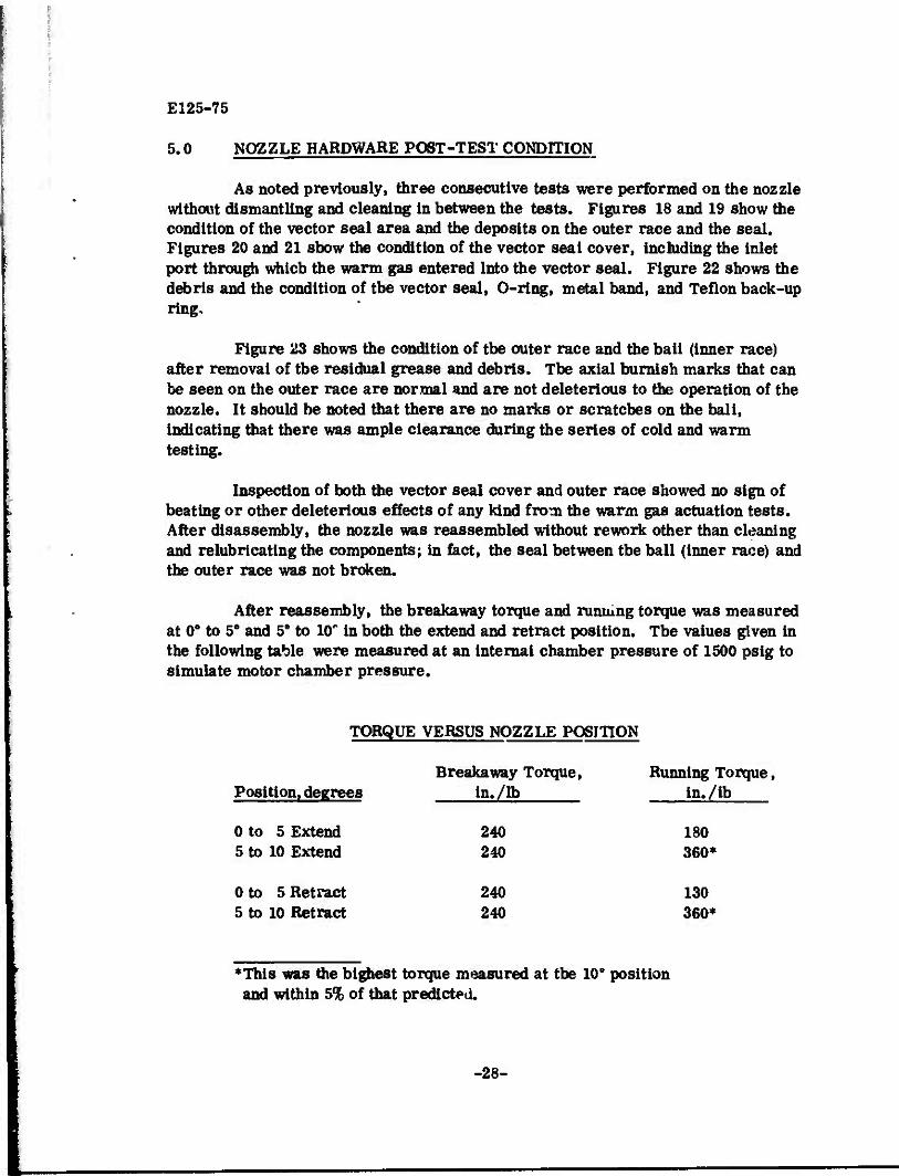
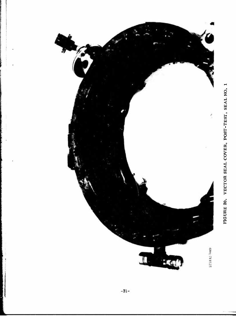
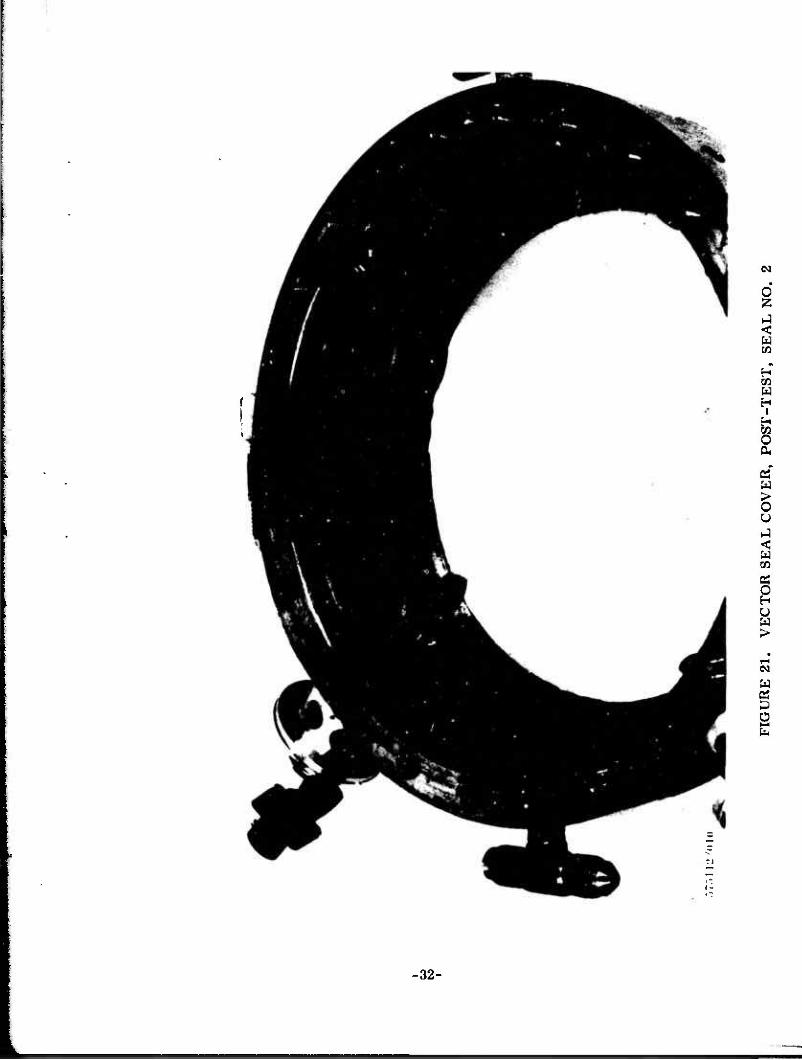
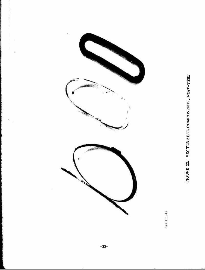
As noted previously, three consecutive tests were performed on the nozzle without dismantling and cleaning in between the tests. Figures 18 and 19 show the condition of the vector seal area and the deposits on the outer race and the seal. Figures 20 and 21 show the condition of the vector seal cover, including the inlet port through which the warm gas entered into the vector seal. Figure 22 shows the debris and the condition of the vector seal, O-ring, metal band, and Teflon back-up ring.
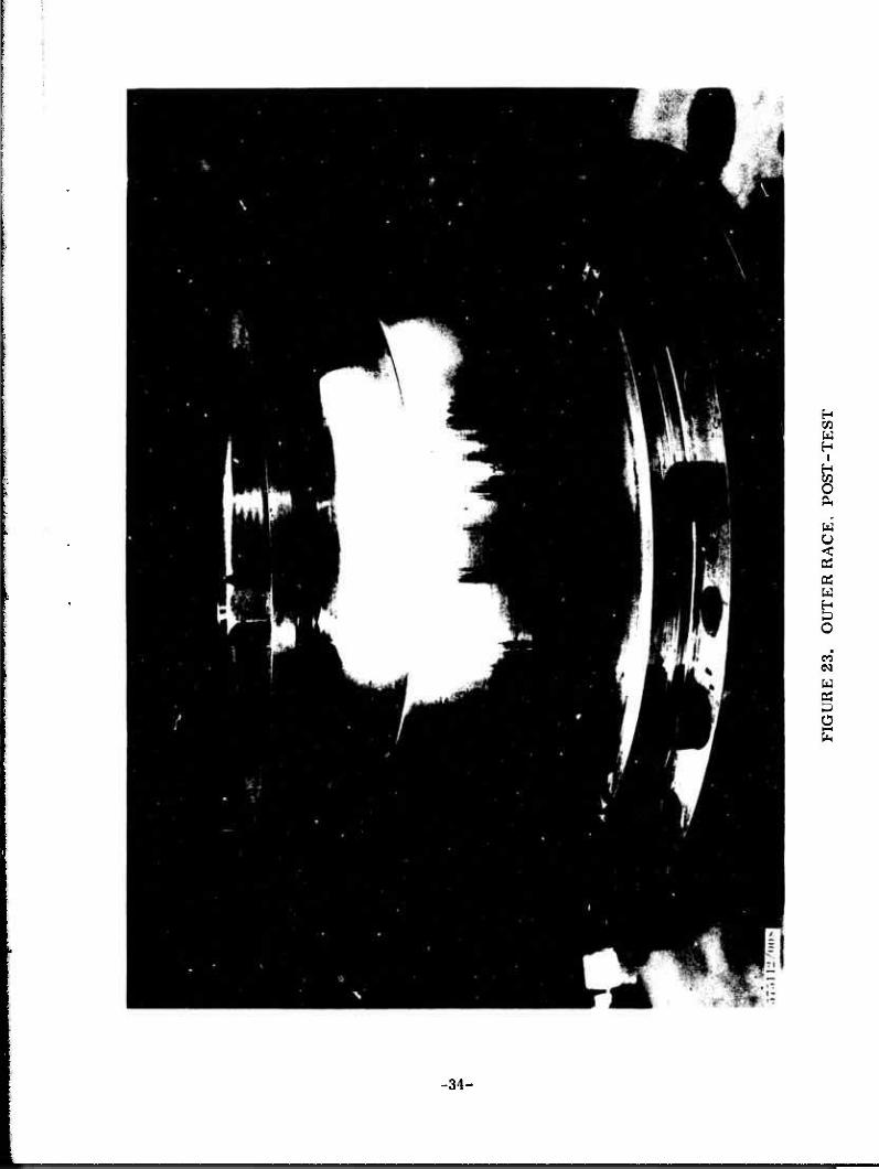
Figure 23 shows the condition of the outer race and the ball (inner race) after removal of the residual grease and debris. The axial burnish marks that can be seen on the outer race are normal and are not deleterious to the operation of the nozzle. It should be noted that there are no marks or scratches on the ball, indicating that there was ample clearance during the series of cold and warm testing.
Inspection of both the vector seal cover and outer race showed no sign of heating or other deleterious effects of any kind from the warm gas actuation tests. After disassembly, the nozzle was reassembled without rework other than cleaning and relubricating the components; in fact, the seal between the ball (inner race) and the outer race was not broken.
After reassembly, the breakaway torque and running torque was measured at 0° to 5° and 5° to 10" in both the extend and retract position. The values given in the following table were measured at an internal chamber pressure of 1500 psig to simulate motor chamber pressure.
TORQUE VERSUS NOZZLE POSITION
Breakaway Torque, Running Torque, Position, degrees In./lb in. /lb
0 to 5 Extend 240 180 5 to 10 Extend 240 360*
0 to 5 Retract 240 130 5 to 10 Retract 240 360*
•This was the highest torque measured at the 10° position and within 5% of that predicted.
-28-

mm
mr*
m
• *•«
.
L
I H
I 1
JUP
'f*i i
vm
w1
iimiii
J 11
iwJi
l to
to
I
FIG
UR
E 1
8.
PO
ST
-TE
ST V
EC
TO
R S
EA
L A
SSE
MB
LY N
O. 1
ilJIlU
MI
>»i
i-ii
ivm
^mm
mm
mm
rm
CO
o
I
FIG
UR
E 1
9.
PO
ST
-TE
ST V
EC
TO
R S
EA
L A
SS
EM
BL
Y N
O. 2
luij
pw
i i i
.uip
u ij
mm
nn
ymi.
wm
mm
mt
I)»"
"
'
—'«
—~
<—
»
,m*
^(W
.'"
-i"
f«
'
-•
T
^—
—
""
ill-
i :r
~ '
BV
1' r
mw
tJU
'.W
I
r»7.
"»iJ2
/<ni
u
FIG
UR
E 2
0.
VE
CT
OR S
EA
L C
OV
ER
, P
OS
T-T
ES
T, S
EA
L N
O. 1
JMN
PM
MO
TI
I CO
to
."»7
5112
(i
In
FIG
UR
E 2
1.
VE
CT
OR S
EA
L C
OV
ER
, P
OS
T-T
ES
T,
SE
AL N
O.
2
II' M
ip.l
..lu
iiji
! n
i ii
iLji
i im
mm
tiiM
I CO
V. -
-
.V«~
.l II
' n
!i>
FIG
UR
E 2
2.
VE
CT
OR S
EA
L C
OM
PO
NE
NT
S,
PO
ST
-TE
ST
Hi
^W
H
'«M
l»»^
1 B
W»»"^
W!»
^W
W
P
CO
FIG
UR
E 2
3.
OU
TE
R R
AC
E,
PO
ST
-TE
ST
E125-75
6.0 CONCLUSIONS
1) The program objective was successfully accomplished in that all test results and the post-test condition of the hardware demonstrated the feasibility of actuating the THIOVEC ®nozzle with warm gas.
2) Since the nozzle hardware was identical to that previously used with a hydraulic fluid actuation system, it can be concluded that the nozzle design features can remain identical and are independent of the type of actuation system, that is, either pneumatic or hydraulic.
3) Phase n of this program has successfully characterized the dynamic response of a warm gas actuated THIOVEC TVC nozzle.
4) Although the nozzle control system was not adjusted or designed for optimum nozzle dynamic characteristics, the nozzle response, phase lag, and slew rate are well within expected requirements for underwater missile TVC systems.
5) The warm gas actuation system produced no nozzle overshoot.
6) Six repetitive warm gas tests using the same nozzle and actuation system hardware with only minimal clean-up after each test have demonstrated the absence of any adverse effects due to warm gas actuation of the THIOVEC® TVC nozzle.
-35-
E125-75
APPENDIX A
NOZZLE DESCRIPTION
1.0 GENERAL
For descriptive purposes, the THIOVEC® TVC nozzle can be considered as consisting of four basic groups of components:
1) THIOVEC® Bearing Assembly
2) Actuator Mechanism
3) Actuation Control System
4) Nozzle Liner (insulation, throat, and exit cone)
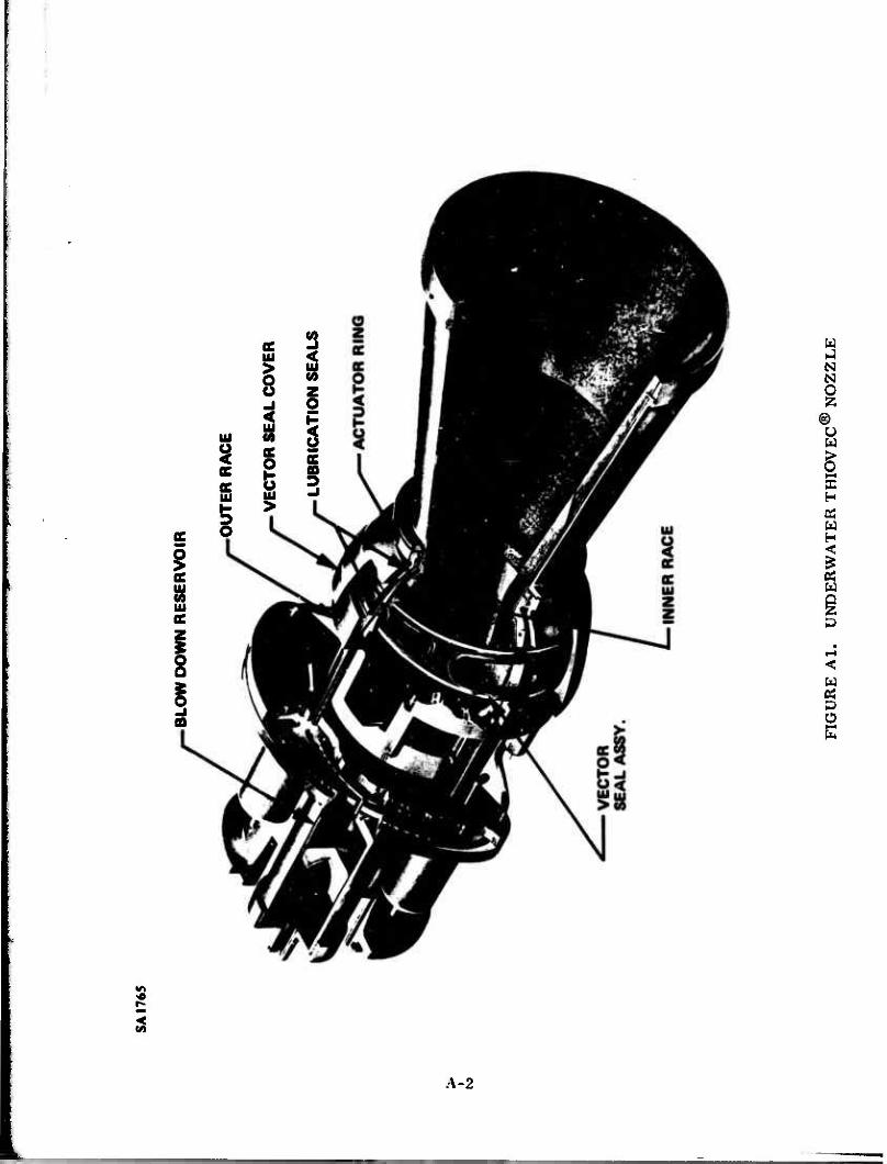
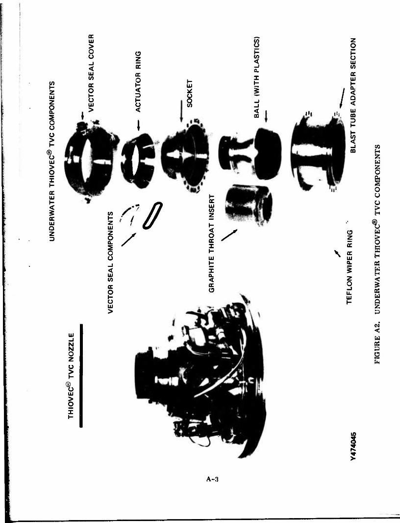
An artist's presentation of a typical THIOVEC® nozzle with cutaway views THIOVEC TVC test are shown in Figures Al and A2.
Only items 1) and 2) above are discussed in this appendix. The Actuation Control Section, Item 3, is discussed in the text of this report. With respect to Item 4),Nozzle liner, the THIOVEC® nozzle structure, which interfaces with and supports the nozzle liner, is no different from that of other movable TVC nozzles.
® 2.0 THIOVEC Bearing Assembly
® The THIOVEC nozzle is basically a ball-and-socket type TVC nozzle. The operating chamber pressure of a rocket motor produces a significant force on the movable ball portion of the nozzle. This force is termed "nozzle blow-out load." This load is reacted against the socket or stationary portion of the nozzle and, in most TVC nozzle designs, causes high friction at the ball-to-socket interface. The most significant feature of the THIOVEC nozzle is the unique method of minimizing the frictional forces resisting movement of the ball within its socket. Frictional forces are low because of the lubricant between the inner r^re (ball) and outer race (socket) of the nozzle. The lubrication seals seal in the lubr ant upon which the inner race "floats." Therefore, the inner race is in contact with only the lubrication seals and lubricant, producing a very-low-friction force resisting rotation of the inner race. Much of ti:e friction force usually found in ball-and-socket type TVC nozzles is replaced by the lower viscous shear force at the ball-lubricant interface.
A-l
mm
m
^^
m*w
m,,
•• .
1.
11 p
ii
SA 1
765
BLO
W D
OW
N R
ES
ER
VO
IR
i to
OU
TE
R R
AC
E
VE
CT
OR
SE
AL
CO
VE
R
LU
BR
ICA
TIO
N S
EA
LS
FIG
UR
E A
l.
UN
DE
RW
AT
ER T
HIO
VE
C®
NO
ZZ
LE
WH
Hfl
M.-
ilf^
fWW
WW
I'il
lWIlL
I
•"•n
^w
i.
,,,-
..„•„.
,.„• j
.iM
UN
DE
RW
AT
ER T
HIO
VE
C®
TV
C C
OM
PO
NE
NTS
TH
IOV
EC
® T
VC N
OZ
ZL
E
>
VE
CT
OR S
EA
L C
OM
PO
NE
NT
S
GR
AP
HIT
E T
HR
OA
T I
NS
ER
T
\
Y47
4045
T
EF
LON W
IPE
R R
ING
VE
CT
OR S
EA
L C
OV
ER
-•-
A
CT
UA
TO
R R
ING
SO
CK
ET
BA
LL (
WIT
H P
LAS
TIC
S)
BLA
ST T
UB
E A
DA
PT
ER S
EC
TIO
N
FIG
UR
E A
2.
UN
DE
RW
AT
ER
TH
IOV
EC
® T
VC C
OM
PO
NE
NT
S
Axial displacement of the inner race occurs in the aft direction at a rate proportional to nozzle blowout load produced by chamber pressure and the axial load produced by the hydraulic actuation system. The nozzle blowout load pressurizes the lubricant, and the subsequent force balance achieved supports the "ball" in its "socket." Axial displacement of the inner race is limited by the extent to which the O-ring lubrication seals are displaced in their grooves and the outer race deflected by the lubrication pressure generated.
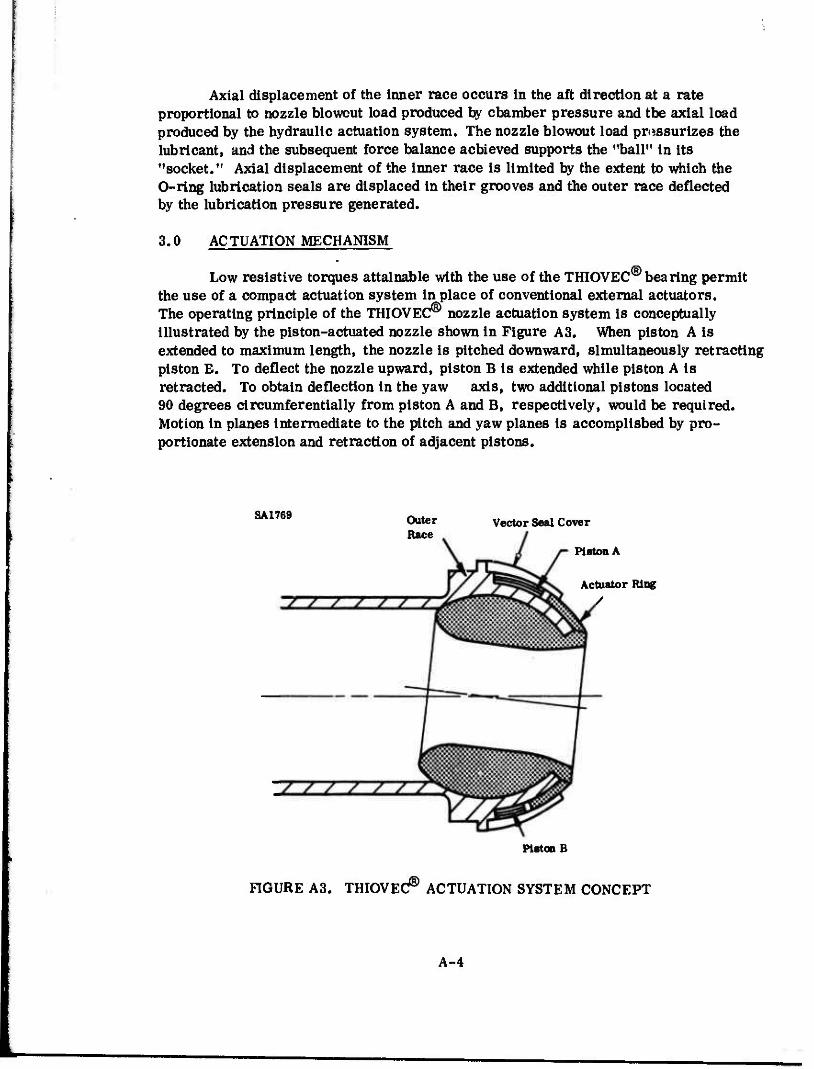
3.0 AC TUATION MECHANISM
Low resistive torques attainable with the use of the THIOVEC® bearing permit the use of a compact actuation system in place of conventional external actuators. The operating principle of the THIOVEC® nozzle actuation system is conceptually illustrated by the piston-actuated nozzle shown in Figure A3. When piston A is extended to maximum length, the nozzle is pitched downward, simultaneously retracting piston B. To deflect the nozzle upward, piston B is extended while piston A is retracted. To obtain deflection in the yaw axis, two additional pistons located 90 degrees circumferentially from piston A and B, respectively, would be required. Motion in planes intermediate to the pitch and yaw planes is accomplished by pro- portionate extension and retraction of adjacent pistons.
SA1769 Outer Race
Vector Seal Cover
Piston A
Actuator Ring /
Piston B
FIGURE A3. THIOVEC^ ACTUATION SYSTEM CONCEPT
A-4

E125-75 In the THIOVEC nozzle, piston functions are performed by four kidney--ahaped
flexible vector-seal assemblies located between the movable actuator ring and a face on the outer race. Kidney-shaped O-rings, with teflon back-up rings contained within their steel bands, are used as the vector seals.
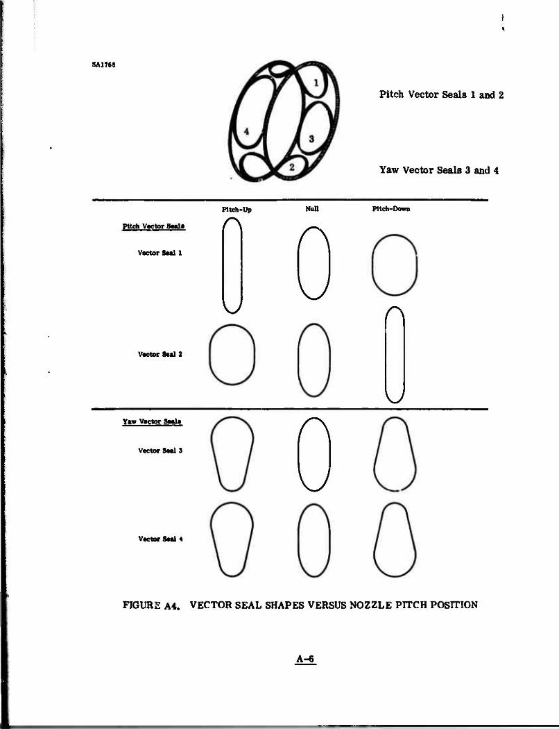
The four vector seals are spaced 90 degrees apart. They flex, as illustrated in Figure A4, during nozzle movement. Figure A4 shows the approximate shape of the four seals at the null, maximum pitch up, and minimum pitch down positions when each seal is viewed perpendicular to the nozzle longitudinal axis. The vector seals are filled with hydraulic fluid that is contained by the inner surface of the vector seal cover and the outer surface of the outer race. Thus, when pressure is applied to the hydraulic fluid, the vector seal attempts to attain a circular form. The actuator ring is forced away causing the nozzle to deflect. The vector seal, 180 degrees from the pressurized seal, is vented to allow nozzle movement.
In Figure A4, note that when the nozzle is vectored in the pitch direction, the yaw seals assume irregular shapes. This produces unbalanced forces tending to rotate the vector seals about the longitudinal axis. In designs such as the Harpoon THIOVEC^ nozzle, where the vector seals are not interconnected but separated, it is necessary to .sstrain each vector seal in its circumferential position by mechanically mating it with the actuator ring and outer race. Rotation of the inner race is resisted by keys mating with longitudinal slots in the accuator ring and attached to the outer race.
Because the vector seal actuation mechanism is contained between the fixed and movable nozzle parts, the nozzle is said to be internally actuated as compared to a TVC nozzle with conventional external actuators.
From the design standpoint, the retracted (compressed) versus the extended (expanded) position of the vector seals must be analyzed. When compressed, the vector seal is longer in the circumferential direction, resulting in an increased effective piston area. Thus, when hydraulic pressure is applied, a force is applied to the actuator ring, a result which, in large, restores torque about the nozzle pivot point. On the other hand, when the vector seal is fully extended, the seal is shorter in the circumferential direction, resulting in a decrease in the effective piston area and providing a reduced torque. Therefore, the piston area varies with the nozzle position. The torque developed is proportional to the piston area times the pressure in the seal.
The three basic torques resisting nozzle movement are lubrication-seal friction, vector-seal friction, and Internal aerodynamic spring torque. Aerodynamic torque is minimized by designing the nozzle throat near the nozzle pivot point.
Actuation fluid is supplied to the vector seals through electromechanical se/vocontrol valves. These are connected by a manifold arrangement. Two servo- control valves are required for omniaxial nozzle motion. As either valve permits pressurization of one vector seal, it simultaneously vents the opposite vector seal.
A-5
SA1768
Pitch Vector Seals 1 and 2
Yaw Vector Seals 3 and 4
Pitch Vector 8—1«
Vector Seal 1
Vector Seal 2
Pitch-Up
\J
Null Pitch-Down
r\
KJ r\
\y
Yaw Vector Seele
Vector Seal 3
Vector Seal 4
r\
\J
FIGURE A4. VECTOR SEAL SHAPES VERSUS NOZZLE PITCH POSITION
A-6


![The Cecil Whig (Elkton, Md.) 1863-02-28 [p ]](https://img.pdfslide.us/doc/110x75/62ae46824dcb543b37596d82/the-cecil-whig-elkton-md-1863-02-28-p-.jpg)