Embed Size (px)
Citation preview
Operator’s Manual
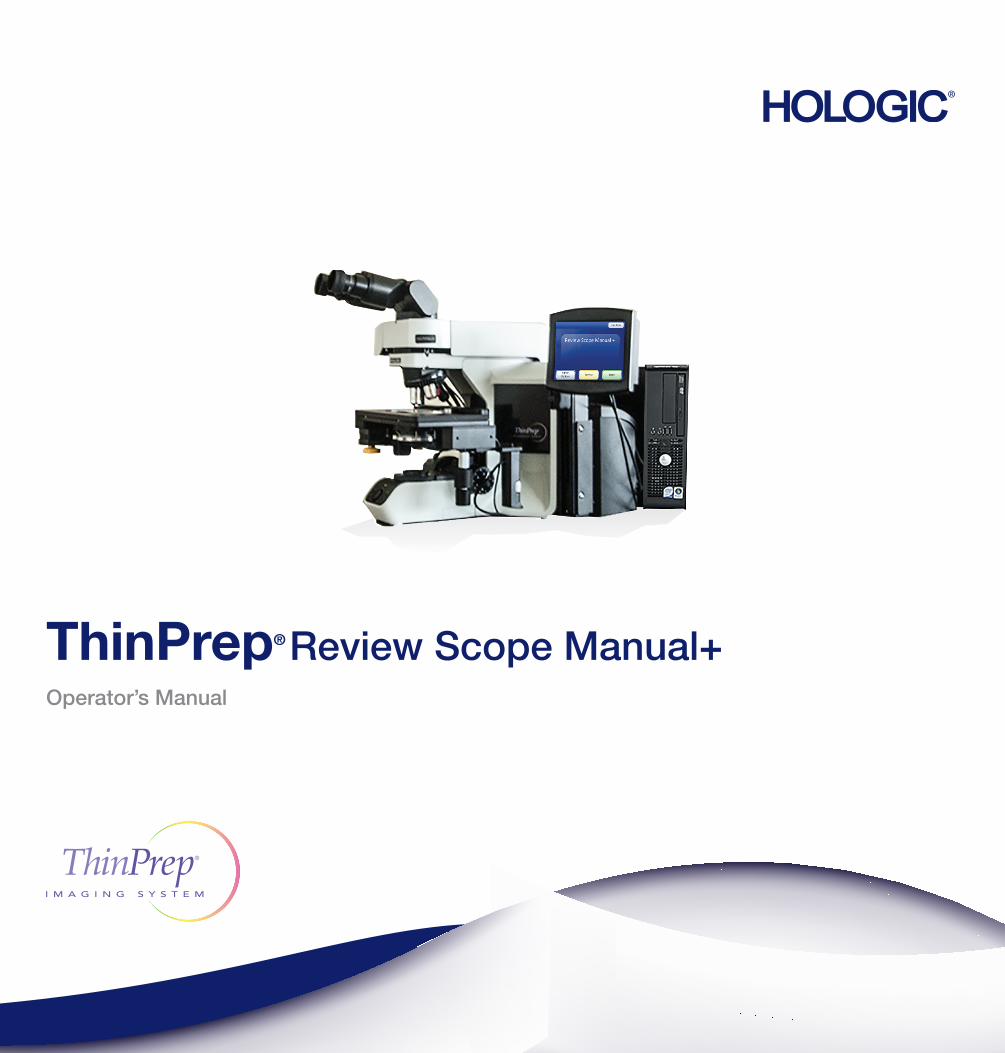
ThinPrep® Review Scope Manual+
ThinPrep® Review Scope Manual+Operator’s Manual
For Use With Version 1.x.y Software
Hologic, Inc.250 Campus DriveMarlborough, MA 01752 USATel: 1-800-442-9892
1-508-263-2900Fax: 1-508-229-2795Web: www.hologic.com

The ThinPrep® Imaging System is a PC-based automated imaging and review system for use with ThinPrep cervical cytology sample slides. The ThinPrep Imaging System is intended to help a cytotechnologist or pathologist highlight areas of a slide for further manual review. The Product is not a replacement for manual review. Determination of slide adequacy and patient diagnosis is at the sole discretion of the cytotechnologists and pathologists trained by Hologic to evaluate ThinPrep- prepared slides. If and only if it is finally determined by a court of competent jurisdiction that the Product sold to Customer hereunder was defective in design or contained a manufacturing defect and that such defect was solely responsible for an error in diagnosis that caused harm to a patient, Hologic shall indemnify Customer for the compensatory damages paid by Customer to discharge the personal injury judgment with respect to Product.
© Hologic, Inc., 2015. All rights reserved. No part of this publication may be reproduced, transmitted, transcribed, stored in a retrieval system, or translated into any language or computer language, in any form, or by any means, electronic, mechanical, magnetic, optical, chemical, manual, or otherwise, without the prior written permission of Hologic, 250 Campus Drive, Marlborough, Massachusetts, 01752, United States of America.
Although this guide has been prepared with every precaution to ensure accuracy, Hologic assumes no liability for any errors or omissions, nor for any damages resulting from the application or use of this information.
This product may be covered by one or more U.S. patents identified at http://www.hologic.com/patentinformation
Hologic, PreservCyt, and ThinPrep are registered trademarks of Hologic, Inc. in the United States and other countries. All other trademarks are the property of their respective companies.
Changes or modifications to this unit not expressly approved by the party responsible for compliance could void the user’s authority to operate the equipment. Use of the ThinPrep Review Scope Manual+ not in accordance with these instructions may void the warranty.
Document Number: AW-10318-001 Rev. 003

Instru
ction
s Fo
r Use In
stru
ctio
ns
Fo
r U
se

Operation Summary and Clinical Information
The ThinPrep® Imaging System

MAN-03938-001 Rev. 002 page 2 of 23
A. INTENDED USE The Hologic ThinPrep® Imaging System (Imager) is a device that uses computer imaging technology to assist in primary cervical cancer screening of ThinPrep Pap Test slides for the presence of atypical cells, cervical neoplasia, including its precursor lesions (Low Grade Squamous Intraepithelial Lesions, High Grade Squamous Intraepithelial Lesions), and carcinoma as well as all other cytologic criteria as defined by 2001 Bethesda System: Terminology for Reporting Results of Cervical Cytology 1.
B. SUMMARY AND EXPLANATION OF THE SYSTEM The ThinPrep Imaging System is an automated imaging and review system for use with ThinPrep Pap Test slides. It combines imaging technology to identify microscopic fields of diagnostic interest with automated stage movement of a microscope in order to locate these fields. In routine use, the ThinPrep Imaging System selects 22 fields of view for a Cytotechnologist to review. Following review of these fields, the Cytotechnologist will either complete the diagnosis if no abnormalities are identified or review the entire slide if any abnormalities are identified. The ThinPrep Imaging System also allows the physical marking of locations of interest for the Cytopathologist.
C. PRINCIPLES OF OPERATION The ThinPrep Imaging System consists of an Image Processor and one, or more, Review Scopes. The system makes use of computer imaging to select fields of view for presentation to a Cytotechnologist on a Review Scope. Slides used with this system must first be prepared on a ThinPrep 2000 or 3000 Processor, and stained with ThinPrep Stain.
The Imaging Processor acquires and processes image data from the slides to identify diagnostically relevant cells or cell groups based on an imaging algorithm that considers cellular features and nuclear darkness. During slide imaging, the alphanumeric slide accession identifier is recorded and the x and y coordinates of 22 fields of interest are stored in the computer database. This computer also coordinates the communication of information between the Image Processor and the Review Scopes.
After image processing, slides are distributed to Cytotechnologists for review utilizing the Review Scopes. The Review Scope is a microscope with an automated stage to facilitate the locating of the 22 fields containing the cells of interest. Additionally, the Review Scope provides a method for automated marking of objects for further review. Slides are individually loaded onto the Review Scope stage, the alphanumeric slide accession identifier is automatically scanned and the stored x and y coordinates representing fields of interest for that slide are electronically downloaded from the computer to the Review Scope. The Cytotechnologist then uses a keypad to step through each of the fields of interest (Autolocate). If the Cytotechnologist identifies any of these fields as containing abnormal objects, that field may be marked electronically. The Review Scope will guide the Cytotechnologist to conduct a review of the entire cell spot for any slide that has had fields electronically marked (Autoscan). The Cytotechnologist determines specimen adequacy and the presence of infections during the review of the 22 fields of view presented by the ThinPrep Imaging System. Either of two methods can be used to determine specimen adequacy. The first method is to count cells and determine the average number of cells in the 22 fields of view presented by the Imager. The second method is to count and determine the average number of cells in 10 fields of view across the diameter of the cell spot. Either method will enable the Cytotechnologist to determine if the minimum cells, as recommended by Bethesda System 2001 criteria, are present on the slide. At the conclusion of the slide review electronically marked objects are automatically ink marked. Any x and y coordinates representing marked locations along with a slide completion status are then electronically transmitted back to the computer for storage.

MAN-03938-001 Rev. 002 page 3 of 23
D. LIMITATIONS Only personnel who have been appropriately trained should operate the ThinPrep® Imaging System
Image Processor or Review Scope.
All slides that undergo primary automated screening with the Image Processor require manual rescreening of the selected fields of view by a Cytotechnologist using a Review Scope.
The ThinPrep Imaging System is only indicated for use with the ThinPrep Pap Test.
The laboratory Technical Supervisor should establish individual workload limits for personnel using the ThinPrep Imaging System. The maximum daily limit specified is only an upper limit and should never be used as an expectation for daily productivity or as a performance target.
The ThinPrep Imaging System has not been proven to be safe or effective at workload levels which exceed product labeling.
ThinPrep slides with fiducial marks must be used.
Slides must be stained using the ThinPrep Stain according to the applicable ThinPrep Imaging System slide staining protocol.
Slides should be clean and free of debris before being placed on the system.
The slide coverslip should be dry and located correctly.
Slides that are broken or poorly coverslipped should not be used.
Slides used with the ThinPrep Imaging System must contain properly formatted accession number identification information as described in the operator’s manual.
Slides once successfully imaged on the Image Processor cannot be imaged again.
The performance of the ThinPrep Imaging System using slides prepared from reprocessed sample vials has not been evaluated; therefore it is recommended that these slides be manually reviewed.
E. WARNINGS The Imager generates, uses, and can radiate radio frequency energy and may cause interference to
radio communications.
A Hologic authorized service representative must install the ThinPrep Imaging System.
F. PRECAUTIONS Caution should be used when loading and unloading glass slides on the ThinPrep Imaging System
to prevent slide breakage and/or injury.
Care should be taken to assure that slides are correctly oriented in the ThinPrep Imaging System cassettes to prevent rejection by the system.
Partially processed slide cassettes should not be removed from the Image Processor, as data may be lost.
The Image Processor should be placed on a flat, sturdy surface away from any vibrating machinery to assure proper operation.
MAN-03938-001 Rev. 002 page 4 of 23
G. PERFORMANCE CHARACTERISTICS A multi-center, two-armed clinical study was performed over an eleven (11) month period at four (4) cytology laboratory sites within the United States. The objective of the study entitled “Multi-Center Trial Evaluating the Primary Screening Capability of the ThinPrep® Imaging System” was to show that routine screening of ThinPrep Pap Test slides using the ThinPrep Imaging System is equivalent to a manual review of ThinPrep slides for all categories used for cytologic diagnosis (specimen adequacy and descriptive diagnosis) as defined by the Bethesda System criteria2.
The two-arm study approach allowed a comparison of the cytologic interpretation (descriptive diagnosis and specimen adequacy) from a single ThinPrep prepared slide, screened first using standard laboratory cervical cytology practices (Manual Review) and then after a 48 day time lag were screened with the assistance of the ThinPrep Imaging System (Imager Review). A subset of slides from the study were reviewed and adjudicated by a panel of three (3) independent Cytopathologists to determine a consensus diagnosis. The consensus diagnosis was used as a “gold standard” for truth to evaluate the results of the study.
G.1 LABORATORY AND PATIENT CHARACTERISTICS
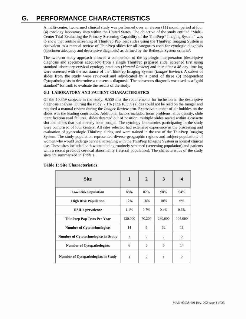
Of the 10,359 subjects in the study, 9,550 met the requirements for inclusion in the descriptive diagnosis analysis. During the study, 7.1% (732/10,359) slides could not be read on the Imager and required a manual review during the Imager Review arm. Excessive number of air bubbles on the slides was the leading contributor. Additional factors included focus problems, slide density, slide identification read failures, slides detected out of position, multiple slides seated within a cassette slot and slides that had already been imaged. The cytology laboratories participating in the study were comprised of four centers. All sites selected had extensive experience in the processing and evaluation of gynecologic ThinPrep slides, and were trained in the use of the ThinPrep Imaging System. The study population represented diverse geographic regions and subject populations of women who would undergo cervical screening with the ThinPrep Imaging System in normal clinical use. These sites included both women being routinely screened (screening population) and patients with a recent previous cervical abnormality (referral population). The characteristics of the study sites are summarized in Table 1.
Table 1: Site Characteristics
Site 1 2 3 4
Low Risk Population 88% 82% 90% 94%
High Risk Population 12% 18% 10% 6%
HSIL+ prevalence 1.1% 0.7% 0.4% 0.6%
ThinPrep Pap Tests Per Year 120,000 70,200 280,000 105,000
Number of Cytotechnologists 14 9 32 11
Number of Cytotechnologists in Study 2 2 2 2
Number of Cytopathologists 6 5 6 14
Number of Cytopathologists in Study 1 2 1 2
MAN-03938-001 Rev. 002 page 5 of 23
G.2 DESCRIPTIVE DIAGNOSIS SENSITIVITY AND SPECIFICITY ESTIMATES
A panel of three independent Cytopathologists adjudicated slides from all discordant (one-grade or higher cytologic difference) descriptive diagnosis cases (639), all concordant positive cases (355) and a random 5% subset of the 8550 negative concordant cases (428). The Cytopathologists on the adjudication panel were board-certified, all of whom had a subspecialty certification in Cytopathology. Their experience levels in Cytopathology ranged from 6 to 12 years. Two of the adjudicators were from university practices and one adjudicator was from a private medical center. The volumes for the adjudicator’s institutions ranged from 12,000 to 30,000 ThinPrep® Pap Tests annually.
A consensus diagnosis was defined as agreement by at least 2 of 3 Cytopathologists. All slides sent to the panel of Cytopathologists were not identified by site nor ordered in any fashion. When a consensus diagnosis could not be obtained by at least 2 of 3 Cytopathologists, the full panel of Cytopathologists reviewed each case simultaneously using a multi-headed microscope to determine a consensus diagnosis.
The adjudicated results were used as a “gold standard” to define the following major “true” descriptive diagnosis classifications of the Bethesda System: Negative, ASCUS, AGUS, LSIL, HSIL, Squamous Cell Carcinoma (SQ CA) and Glandular Cell Carcinoma (GL CA). Estimates of sensitivity and specificity together with 95% confidence intervals were calculated for the Manual Review and Imager Review arms of the study. The differences in sensitivity and specificity between the two arms, together with their 95% confidence intervals were also calculated. Among the random 5% subset of 8,550 cases (428 slides) that were found to be negative by both arms and adjudicated, there were 425 “true” negative and 3 “true” ASCUS slides. A multiple imputation technique was used to adjust the numbers of true positives and true negatives for the 8,550 negative concordant cases based on the 5% of cases that were adjudicated3.
Tables 2-4 below summarize the descriptive diagnosis sensitivity and specificity estimates with 95% confidence intervals for each of the four sites and all sites combined for “true” ASCUS+, LSIL+ and HSIL+.
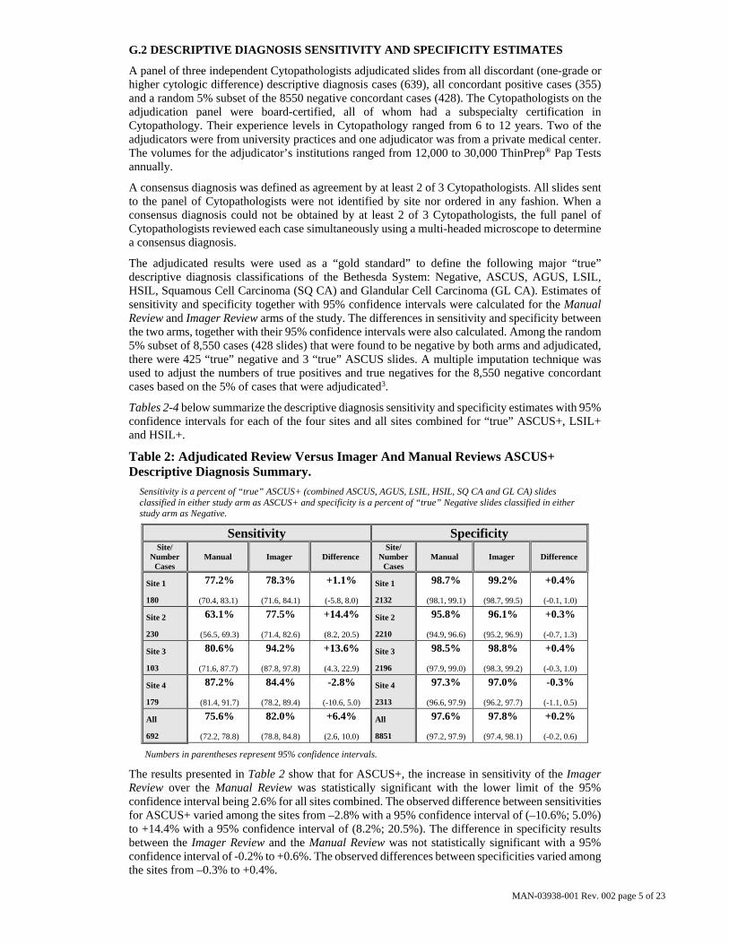
Table 2: Adjudicated Review Versus Imager And Manual Reviews ASCUS+ Descriptive Diagnosis Summary.
Sensitivity is a percent of “true” ASCUS+ (combined ASCUS, AGUS, LSIL, HSIL, SQ CA and GL CA) slides classified in either study arm as ASCUS+ and specificity is a percent of “true” Negative slides classified in either study arm as Negative.
Sensitivity Specificity Site/
Number Cases
Manual Imager Difference Site/
Number Cases
Manual Imager Difference
Site 1
180
77.2%
(70.4, 83.1)
78.3%
(71.6, 84.1)
+1.1%
(-5.8, 8.0)
Site 1
2132
98.7%
(98.1, 99.1)
99.2%
(98.7, 99.5)
+0.4%
(-0.1, 1.0)
Site 2
230
63.1%
(56.5, 69.3)
77.5%
(71.4, 82.6)
+14.4%
(8.2, 20.5)
Site 2
2210
95.8%
(94.9, 96.6)
96.1%
(95.2, 96.9)
+0.3%
(-0.7, 1.3)
Site 3
103
80.6%
(71.6, 87.7)
94.2%
(87.8, 97.8)
+13.6%
(4.3, 22.9)
Site 3
2196
98.5%
(97.9, 99.0)
98.8%
(98.3, 99.2)
+0.4%
(-0.3, 1.0)
Site 4
179
87.2%
(81.4, 91.7)
84.4%
(78.2, 89.4)
-2.8%
(-10.6, 5.0)
Site 4
2313
97.3%
(96.6, 97.9)
97.0%
(96.2, 97.7)
-0.3%
(-1.1, 0.5)
All
692
75.6%
(72.2, 78.8)
82.0%
(78.8, 84.8)
+6.4%
(2.6, 10.0)
All
8851
97.6%
(97.2, 97.9)
97.8%
(97.4, 98.1)
+0.2%
(-0.2, 0.6)
Numbers in parentheses represent 95% confidence intervals.
The results presented in Table 2 show that for ASCUS+, the increase in sensitivity of the Imager Review over the Manual Review was statistically significant with the lower limit of the 95% confidence interval being 2.6% for all sites combined. The observed difference between sensitivities for ASCUS+ varied among the sites from –2.8% with a 95% confidence interval of (–10.6%; 5.0%) to +14.4% with a 95% confidence interval of (8.2%; 20.5%). The difference in specificity results between the Imager Review and the Manual Review was not statistically significant with a 95% confidence interval of -0.2% to +0.6%. The observed differences between specificities varied among the sites from –0.3% to +0.4%.

MAN-03938-001 Rev. 002 page 6 of 23
Table 3: Adjudicated Review Versus Imager Review LSIL+ Descriptive Diagnosis Summary for Each Site and All Sites Combined.
Sensitivity is a percent of “true” LSIL+ (combined LSIL, HSIL, SQ CA and GL CA) slides classified in either study arm as LSIL+ and specificity is a percent of “true” Non-LSIL+ (combined Negative, ASCUS, AGUS) slides classified in either study arm as Non-LSIL+.
Sensitivity Specificity Site/
Number Cases
Manual Imager Difference Site/
Number Cases
Manual Imager Difference
Site 1
104
84.6%
(76.2, 90.9)
82.7%
(74.0, 89.4)
-1.9%
(-9.5, 5.6)
Site 1
2208
98.7%
(98.1, 99.1)
99.3%
(98.9, 99.6)
+0.6%
(0.1, 1.0)
Site 2
98
70.4%
(60.3, 79.2)
72.4%
(62.5, 81.0)
+2.0%
(-6.9, 11.0)
Site 2
2342
99.3%
(98.8, 99.6)
98.9%
(98.4, 99.3)
-0.4%
(-0.8, .001)
Site 3
62
77.4%
(65.0, 87.1)
85.5%
(74.2, 93.1)
+8.1%
(-4.0, 20.1)
Site 3
2237
99.2%
(98.7, 99.5)
99.5%
(99.1, 99.8)
+0.3%
(-0.1, 0.6)
Site 4
111
84.7%
(98.1, 99.1)
78.4%
(76.6, 90.8)
-6.3%
(-14.7, 2.1)
Site 4
2381
98.7%
(98.2, .99.2)
98.7%
(98.1, 99.1)
-0.08%
(-0.6, 0.4)
All
375
79.7%
(75.3, 83.7)
79.2%
(74.7, 83.2)
-0.5%
(-5.0, 4.0)
All
9168
99.0%
(98.8, 99.2)
99.1%
(98.9, 99.3)
+0.09%
(-0.1, 0.3)
Numbers in parentheses represent 95% confidence intervals.
The results presented in Table 3 show that the difference between sensitivities of the Imager Review and Manual Review arms for LSIL+ for all sites combined was not statistically significant with a 95% confidence interval of –5.0% to +4.0%. The observed difference between sensitivities for LSIL+ varied among the sites from –6.3% with a 95% confidence interval of (–14.7%; 2.1%) to +8.1% with a 95% confidence interval of (–4.0%; 20.1%). The difference in specificity results between the Imager Review and the Manual Review was not statistically significant with a 95% confidence interval of -0.1% to +0.3%. The observed differences between specificities varied among the sites from –0.4% to +0.6%.
Table 4: Adjudicated Review Versus Imager Review HSIL+ Descriptive Diagnosis Summary for Each Site and All Sites Combined.
Sensitivity is a percent of “true” HSIL+ (combined HSIL, SQ CA and GL CA) slides classified in either study arm as HSIL+ and specificity is a percent of “true” Non-HSIL+ (combined Negative, ASCUS, AGUS, LSIL) slides classified in either study arm as Non-HSIL+.
Sensitivity Specificity Site/
Number Cases
Manual Imager Difference Site/
Number Cases
Manual Imager Difference
Site 1
38
89.5%
(75.2, 97.1)
92.1%
(78.6, 98.3)
2.6%
(-8.9, 14.1)
Site 1
2274
98.8%
(98.3, 99.2)
99.5%
(99.1, 99.8)
+0.7%
(0.2, 1.2)
Site 2
40
72.5%
(56.1, 85.4)
70.0%
(53.4, 83.4)
-2.5%
(-15.4, 10.4)
Site 2
2400
99.8%
(99.5, 99.9)
99.6%
(99.2, 99.8)
-0.1%
(-0.3, .09)
Site 3
22
72.7%
(49.8, 89.3)
86.4%
(65.1, 97.1)
+13.6%
(-0.7, 28.0)
Site 3
2277
99.7%
(99.4, 99.9)
99.7%
(99.4, 99.9)
0%
(-0.2, 0.2)
Site 4
39
61.5%
(44.6, 76.6)
74.4%
(57.9, 87.0)
+12.8%
(-1.7, 27.4)
Site 4
2453
99.5%
(99.2, 99.8)
99.8%
(99.5, 99.9)
+0.3%
(-0.003, 0.6)
All
139
74.1%
(66.0, 81.2)
79.9%
(72.2, 86.2)
+5.8%
(-1.1, 12.6)
All
9404
99.4 %
(99.2, 99.6)
99.6%
(99.5, 99.7)
+0.2%
(0.06, 0.4)
Numbers in parentheses represent 95% confidence intervals.

MAN-03938-001 Rev. 002 page 7 of 23
The results presented in Table 4 show that the difference between sensitivities of the Imager Review and Manual Review arms for HSIL+ for all sites combined was not statistically significant with a 95% confidence interval of -1.1% to +12.6%. The observed difference between sensitivities for HSIL+ varied among the sites from –2.5% with a 95% confidence interval of (–15.4%; 10.4%) to +13.6% with a 95% confidence interval of (–0.7%; 28.0%). The increase in specificity of the Imager Review over the Manual Review was statistically significant with a 95% confidence interval of +0.06% to +0.4%. The observed differences between specificities varied among the sites from –0.1% to +0.7%.
Tables 5-9 show the performance of the Imager Review and Manual Review compared to the final consensus diagnosis made by the adjudication panel (truth) for the following major descriptive diagnosis classifications of the Bethesda System: Negative, ASCUS, AGUS, LSIL, HSIL, Cancer* (CA) *Includes SQ CA and GL CA. Abbreviations for Diagnoses: NEG = Normal or negative, ASCUS = Atypical Squamous Cells of Undetermined Significance, AGUS = Atypical Glandular Cells of Undetermined Significance, LSIL = Low-grade Squamous Intraepithelial Lesion, HSIL = High-grade Squamous Intraepithelial Lesion, SQ CA = Squamous Cell Carcinoma, GL CA = Glandular Cell Adenocarcinoma.
Table 5: 6x6 “True Negative” Contingency Table For All Sites Combined
All 786 Cases Determined To Be Negative By Adjudication
Unadjudicated Manual Review Arm Diagnosis
Un
adju
dic
ated
Im
ager
R
evie
w A
rm D
iagn
osis
NEG ASCUS AGUS LSIL HSIL CA TOTAL
NEG 425 138 6 10 6 2 587
ASCUS 130 39 1 3 - - 173
AGUS 5 - - - - - 5
LSIL 9 5 - 2 - - 16
HSIL 1 1 - - 3 - 5
CA - - - - - - 0
TOTAL 570 183 7 15 9 2 786
Among the 786 cases determined by the adjudication panel to be Negative, 587 (74.7%) cases in the Imager Review arm and 570 (72.5%) cases in the Manual Review arm were diagnosed as Negative and 21 (2.7%) cases in the Imager Review arm and 26 (3.3%) cases in the Manual Review arm were diagnosed as LSIL+.
Table 6: 6x6 “True ASCUS” Contingency Table For All Sites Combined
All 251 Cases Determined To Be ASCUS By Adjudication
Unadjudicated Manual Review Arm Diagnosis
Un
adju
dic
ated
Im
ager
R
evie
w A
rm D
iagn
osis
NEG ASCUS AGUS LSIL HSIL CA TOTAL
NEG 3 32 - 7 3 - 45
ASCUS 70 47 1 20 4 - 142
AGUS 1 - - - - - 1
LSIL 6 21 - 16 7 - 50
HSIL 2 3 - 5 1 1 12
CA 1 - - - - - 1
TOTAL 83 103 1 48 15 1 251
Among the 251 cases determined by the adjudication panel to be ASCUS, 142 (56.6%) cases in the Imager Review arm and 103 (41.0%) cases in the Manual Review arm were diagnosed as ASCUS and 45 (17.9%) cases in the Imager Review arm and 83 (33.1%) cases in the Manual Review arm were diagnosed as Negative.

MAN-03938-001 Rev. 002 page 8 of 23
Table 7: 6x6 “True AGUS” Contingency Table For All Sites Combined
All 10 Cases Determined To Be AGUS By Adjudication
Unadjudicated Manual Review Arm Diagnosis
Un
adju
dic
ated
Im
ager
R
evie
w A
rm D
iagn
osis
NEG ASCUS AGUS LSIL HSIL CA TOTAL
NEG - 2 1 - 1 - 4
ASCUS - - 1 - - - 1
AGUS 2 - 1 - - 1 4
LSIL - - - - - - 0
HSIL - - - - - - 0
CA - - - - - 1 1
TOTAL 2 2 3 0 1 2 10
Among the 10 cases determined by the adjudication panel to be AGUS, 4 (40.0%) cases in the Imager Review arm and 3 (30.0%) cases in the Manual Review arm were diagnosed as AGUS and 4 (40.0%) cases in the Imager Review arm and 2 (20.0%) cases in the Manual Review arm were diagnosed as Negative.
Table 8: 6x6 “True LSIL” Contingency Table For All Sites Combined
All 236 Cases Determined To Be LSIL By Adjudication
Unadjudicated Manual Review Arm Diagnosis
Un
adju
dic
ated
Im
ager
R
evie
w A
rm D
iagn
osis
NEG ASCUS AGUS LSIL HSIL CA TOTAL
NEG - 4 - 12 1 - 17
ASCUS 13 16 - 20 1 - 50
AGUS - - - - - - 0
LSIL 8 20 - 115 12 - 155
HSIL - - - 5 9 - 14
CA - - - - - - 0
TOTAL 21 40 0 152 23 0 236
Among the 236 cases determined by the adjudication panel to be LSIL, 155 (65.6%) cases in the Imager Review arm and 152 (64.4%) cases in the Manual Review arm were diagnosed as LSIL and 17 (7.2%) cases in the Imager Review arm and 21 (8.9%) cases in the Manual Review arm were diagnosed as Negative.
Table 9: 6x6 “True HSIL” Contingency Table For All Sites Combined
All 138 Cases Determined To Be HSIL By Adjudication
Unadjudicated Manual Review Arm Diagnosis
Un
adju
dic
ated
Im
ager
R
evie
w A
rm D
iagn
osis
NEG ASCUS AGUS LSIL HSIL CA TOTAL
NEG - 1 - - 1 - 2
ASCUS 2 4 - 2 1 - 9
AGUS - - - - - - 0
LSIL 1 - - 10 6 - 17
HSIL 3 3 1 9 91 1 108
CA - - - - 1 1 2
TOTAL 6 8 1 21 100 2 138

MAN-03938-001 Rev. 002 page 9 of 23
Among the 138 cases determined by the adjudication panel to be HSIL, 108 (78.3%) cases in the Imager Review arm and 100 (72.5%) cases in the Manual Review arm were diagnosed as HSIL and 2 (1.4%) cases in the Imager Review arm and 6 (4.3%) cases in the Manual Review arm were diagnosed as Negative.
There was one (1) squamous cell carcinoma (SQ CA) case resulting from adjudication. It was diagnosed as HSIL in the Imager Review arm and SQ CA in the Manual Review arm.
Table 10 shows the study subjects unadjudicated descriptive diagnosis marginal frequencies for benign cellular changes for all sites combined.
Table 10: Unadjudicated Marginal Frequencies Summary of Descriptive Diagnosis for Benign Cellular Changes – All Sites Combined.
Manual Review Imager Review
Number of Patients: 9550 9550
Descriptive Diagnosis N % N %
Benign Cellular Changes: 405 4.2 293 3.1
Infection:
Trichomonas Vaginalis 8 0.1 8 0.1 Fungal organisms consistent with Candida spp. 47 0.5 31 0.3
Predominance of coccobacilli 71 0.7 60 0.6
Bacteria consistent with Actinomyces spp. 1 0.0 1 0.0
Cellular Changes associated with Herpes virus 1 0.0 1 0.0
Other Infection 1 0.0 0 0.0
Reactive Cellular Changes Associated with:
Inflammation 218 2.3 156 1.6
Atrophic with inflammation (atrophic vaginitis) 68 0.7 46 0.5
Radiation 0 0.0 0 0.0
Intrauterine contraceptive device (IUD) 0 0.0 0 0.0
Other Reactive Cellular Change 34 0.4 14 0.1 Note: Some patients had more than one diagnostic subcategory.
The Manual Review showed a higher rate of Benign Cellular Changes (405) than the Imager Review cases (293).
G.3 ANALYTICAL PERFORMANCE OF THINPREP IMAGING SYSTEM FOR DETECTION OF CERVICAL CANCER USING THINPREP® PAP TEST SLIDES FRESHLY PREPARED FROM ARCHIVAL SAMPLES
This analytical study was conducted to compare the Bethesda System 2001 results, obtained by a Cytotechnologist and a Cytopathologist, when their review was limited to 22 fields that were selected by the ThinPrep Imaging System, to their diagnostic results obtained from their independent blinded review of the entire cell spot on the ThinPrep Pap Test slides. All of the reviews were performed in an independent and blinded manner. The test materials consisted of 33 archival PreservCyt-preserved cervical samples that had been previously diagnosed as AGUS or cancer. One ThinPrep Pap Test slide was freshly prepared from each of the 33 original PreservCyt vials. All of the ThinPrep slides used in the study were made on the TP-2000 processor and stained with ThinPrep Stain. Based on the current cervical cancer prevalence rate in the United States, 33 cases of cervical cancer would represent the number of invasive cervical cancer cases in a population of approximately 275,000 women4. Initially, a board-certified Cytopathologist manually reviewed all of the fields on the ThinPrep Pap Test slides and identified and recorded the number of individual cancer cells and clusters of cancer cells that were present. For this part of the study, the Cytopathologist was not required to record any other cells with other Bethesda System 2001 diagnoses. The 33 cases included slides that represented both rare numbers of cancer cells (5-20 per slide), and numerous cancer cells (>20/slide). Cancer cells were categorized according to Bethesda System 2001 criteria for Glandular Cancer, Adenocarcinoma-in-situ and Squamous Cell Cancer. Each slide was then processed on a ThinPrep Imaging System. The Cytotechnologist then reviewed only the 22 fields of view presented by the Autolocate mode of the Review Scope. No review outside of the selected 22 fields of view was permitted. For each field of view, the Cytotechnologist counted and recorded all abnormal cell types based on the following seven Bethesda System classifications: ASCUS, LSIL, HSIL, AGUS, Glandular Cancer, Squamous Cell Carcinoma and Adenocarcinoma-In-Situ.
MAN-03938-001 Rev. 002 page 10 of 23
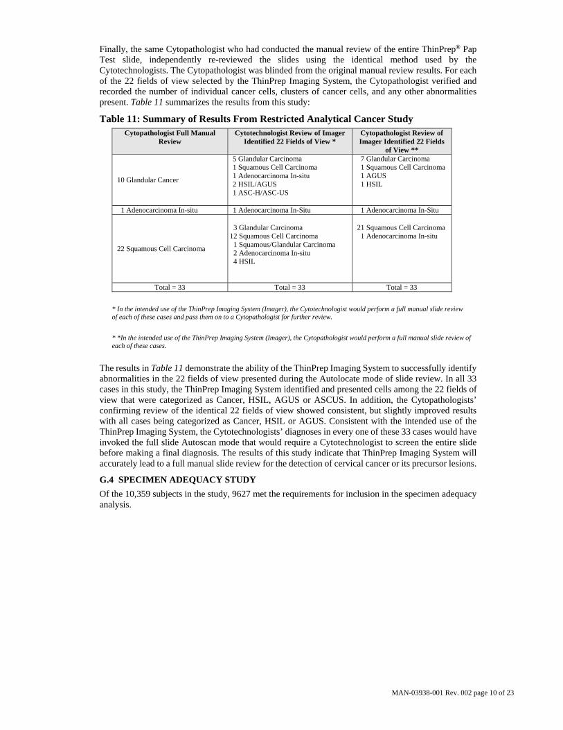
Finally, the same Cytopathologist who had conducted the manual review of the entire ThinPrep® Pap Test slide, independently re-reviewed the slides using the identical method used by the Cytotechnologists. The Cytopathologist was blinded from the original manual review results. For each of the 22 fields of view selected by the ThinPrep Imaging System, the Cytopathologist verified and recorded the number of individual cancer cells, clusters of cancer cells, and any other abnormalities present. Table 11 summarizes the results from this study:
Table 11: Summary of Results From Restricted Analytical Cancer Study Cytopathologist Full Manual
Review Cytotechnologist Review of Imager
Identified 22 Fields of View * Cytopathologist Review of Imager Identified 22 Fields
of View **
10 Glandular Cancer
5 Glandular Carcinoma 1 Squamous Cell Carcinoma 1 Adenocarcinoma In-situ 2 HSIL/AGUS 1 ASC-H/ASC-US
7 Glandular Carcinoma 1 Squamous Cell Carcinoma 1 AGUS 1 HSIL
1 Adenocarcinoma In-situ 1 Adenocarcinoma In-Situ 1 Adenocarcinoma In-Situ
22 Squamous Cell Carcinoma
3 Glandular Carcinoma 12 Squamous Cell Carcinoma 1 Squamous/Glandular Carcinoma 2 Adenocarcinoma In-situ 4 HSIL
21 Squamous Cell Carcinoma 1 Adenocarcinoma In-situ
Total = 33 Total = 33 Total = 33
* In the intended use of the ThinPrep Imaging System (Imager), the Cytotechnologist would perform a full manual slide review of each of these cases and pass them on to a Cytopathologist for further review.
* *In the intended use of the ThinPrep Imaging System (Imager), the Cytopathologist would perform a full manual slide review of each of these cases.
The results in Table 11 demonstrate the ability of the ThinPrep Imaging System to successfully identify abnormalities in the 22 fields of view presented during the Autolocate mode of slide review. In all 33 cases in this study, the ThinPrep Imaging System identified and presented cells among the 22 fields of view that were categorized as Cancer, HSIL, AGUS or ASCUS. In addition, the Cytopathologists’ confirming review of the identical 22 fields of view showed consistent, but slightly improved results with all cases being categorized as Cancer, HSIL or AGUS. Consistent with the intended use of the ThinPrep Imaging System, the Cytotechnologists’ diagnoses in every one of these 33 cases would have invoked the full slide Autoscan mode that would require a Cytotechnologist to screen the entire slide before making a final diagnosis. The results of this study indicate that ThinPrep Imaging System will accurately lead to a full manual slide review for the detection of cervical cancer or its precursor lesions.
G.4 SPECIMEN ADEQUACY STUDY
Of the 10,359 subjects in the study, 9627 met the requirements for inclusion in the specimen adequacy analysis.

MAN-03938-001 Rev. 002 page 11 of 23
Table 12: Unadjudicated Marginal Frequencies Summary of Specimen Adequacy Results – All Sites Combined.
Manual Review Imager Review
Number of Patients: 9627 9627
Descriptive Diagnosis N % N %
Satisfactory for Evaluation 7375 76.6 7346 76.3
Satisfactory but Limited by 2186 22.7 2252 23.4
Endocervical Component Absent 1196 12.4 1397 14.5
Scant Squamous Epithelial Component 92 1.0 102 1.1
Obscuring Blood 45 0.5 17 0.2
Obscuring Inflammation 69 0.7 68 0.7
No Clinical History 982 10.2 933 9.7
Cytolysis 4 0.0 2 0.0
Other 6 0.1 33 0.3
Unsatisfactory for Evaluation 66 0.7 29 0.3
Endocervical Component Absent 6 0.1 0 0.0
Scant Squamous Epithelial Component 35 0.4 22 0.2
Obscuring Blood 17 0.2 2 0.0
Obscuring Inflammation 8 0.1 5 0.1
No Clinical History 2 0.0 2 0.0
Cytolysis 0 0.0 0 0.0
Other 2 0.0 0 0.0
Note: Some patients had more than one diagnostic subcategory.
For SAT cases, there was agreement between the Manual Review cases (7375) and the Imager Review cases (7346). For SBLB cases, there is agreement between the Manual Review cases (2186) and the Imager Review cases (2252). Unsatisfactory cases were greater in the Manual Review cases (66) versus the Imager Review cases (29).
The adjudicated results were used as a “gold standard” to define “true” specimen adequacy classifications of the Bethesda System: SAT/SBLB and UNSAT. There were 58 “true” UNSAT cases and 9569 “true” SAT/SBLB cases.
Table 13 below summarizes specimen adequacy performance for the Imager Review and Manual Review arms for all four sites and all sites combined using the Bethesda System 1991 criteria.
Table 13: Adjudicated Review Versus Imager Review Specimen Adequacy Summary for All Sites and All Sites Combined. Sensitivity is a percent of “true” UNSAT slides classified in either study arm as UNSAT and specificity is a percent of “true” SAT/SBLB slides classified in either study arm as SAT/SBLB.
Sensitivity Specificity Site/
Number Cases
Manual Imager Difference Site/
Number Cases
Manual Imager Difference
Site 1
21
0%
(0/21)
0%
(0/21)
0.0%
(0/21)
Site 1
2292
100%
(2292/2292)
100%
(2292/2292)
0.0%
(0/2292)
Site 2
6
100%
(6/6)
16.7%
(1/6)
-83.3%
(-5/6)
Site 2
2476
98.9%
(2449/2476)
99.6%
(2465/2476)
+0.6%
(16/2476)
Site 3
5
80.0%
(4/5)
60.0%
(3/5)
-20.0%
(-1/5)
Site 3
2323
99.2%
(2304/2323)
99.7%
(2315/2323)
+0.5%
(11/2323)
Site 4
26
30.8%
(8/26)
19.2%
(5/26)
-11.5%
(-3/26)
Site 4
2478
99.9%
(2475/2478)
99.9%
(2476/2478)
+0.04%
(1/2478)
All 58 CI*
29.3% (17/58)
(18.1, 42.7)
13.8% (8/58)
(6.1, 25.4)
-15.5% (-9/58)
(-25.9, -5.0)
All 9569 CI*
99.5% (9520/9569) (99.3, 99.6)
99.8% (9548/9569) (99.7, 99.9)
+0.3% (28/9569) (0.2, 0.4)
All ThinPrep® slides that produced discordant unsatisfactory determinations (Manual Review arm
*95% Confidence Interval

MAN-03938-001 Rev. 002 page 12 of 23
vs. Imager Review arm) during the clinical study were assessed in an additional clinical support study to compare the method used for specimen adequacy in the clinical study with a control cell count of the slides and 3 different methods as follows: (1) Manual assessment of specimen adequacy on the entire microscope slide based on ThinPrep Bethesda System 1991 criteria; (2) Using the “diameter” method of Bethesda System 2001, which requires that the Cytotechnologist counts cells in 10 fields of view along the diameter of the cell spot and calculate the number of cells on the slide; (3) Having the Cytotechnologist count the cells in the 22 fields of view presented by the system and calculate the number of cells on the slide.
This additional support study demonstrated that the Bethesda System 1991 estimation methods, including the method used in the clinical study, do not generate similar specimen adequacy determinations when compared against each other or with the control method. Therefore, the recommended methods for determining specimen adequacy on the ThinPrep Imaging System are (1) the Bethesda System 2001 count of fields along a diagonal of the cell spot or (2) counting the cells in the 22 fields-of-view selected by the ThinPrep Imager System. Refer to the ThinPrep Imaging System Review Scope Operator’s Manual for instructions on the proper use of these methods.
G.5 CYTOTECHNOLOGIST SCREENING RATES Daily Cytotechnologist screening rates were recorded throughout the duration of the clinical study. The study was conducted in a manner designed to reproduce actual clinical conditions. Eight (8) Cytotechnologists participated in the study; two (2) at each clinical site. The experience levels of the Cytotechnologists ranged from 5 to 23 years. During the study the Cytotechnologist’s screening times for the Imager Review arm included automated screening of the 22 fields of view with subsequent full side review of abnormal slides. A full slide review consists of approximately 120 fields of view. The number of hours each Cytotechnologist screened slides per day varied due to logistical issues and scheduling. With the ThinPrep Imaging System, Cytotechnologist screening rates were uniformly faster than the Manual Review method.
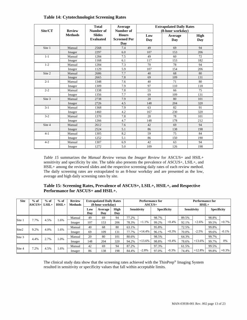
Table 14 summarizes the Cytotechnologist screening rates for both the Imager Review and the Manual Review methods. The total number of slides reviewed in the study and the average number of hours screened per day are presented for each Cytotechnologist and site. Screening rates (extrapolated to an 8 hour workday) are presented as the low, average and high daily screening rates achieved by each Cytotechnologist and site. The low and high daily rates were selected from the lowest and highest daily hourly rates, respectively, and are extrapolated to 8 hours.
MAN-03938-001 Rev. 002 page 13 of 23
Table 14: Cytotechnologist Screening Rates
Site/CT
Review
Methods
Total Number of
Slides Evaluated
Average Number of
Hours Screened Per
Day
Extrapolated Daily Rates (8-hour workday)
Low Day
Average Day
High Day
Site 1 Manual 2568 7.4 49 69 94 Imager 2297 6.0 107 153 206
1-1 Manual 1284 7.5 49 60 72 Imager 1168 6.1 117 153 182
1-2 Manual 1284 7.3 70 78 94 Imager 1129 5.9 107 154 206
Site 2 Manual 2686 7.7 40 68 80 Imager 2665 7.8 69 109 131
2-1 Manual 1348 7.6 40 71 80 Imager 1309 7.9 97 110 118
2-2 Manual 1338 7.8 55 66 75 Imager 1356 7.7 69 109 131
Site 3 Manual 2738 7.9 20 80 101 Imager 2726 4.5 148 204 320
3-1 Manual 1368 7.9 63 82 91 Imager 1460 4.2 167 230 320
3-2 Manual 1370 7.8 20 78 101 Imager 1266 4.7 148 178 212
Site 4 Manual 2612 7.6 42 69 94 Imager 2524 5.1 86 138 198
4-1 Manual 1305 8.2 59 75 84 Imager 1252 5.1 86 150 190
4-2 Manual 1307 6.9 42 63 94 Imager 1272 5.0 109 126 198
Table 15 summarizes the Manual Review versus the Imager Review for ASCUS+ and HSIL+ sensitivity and specificity by site. The table also presents the prevalence of ASCUS+, LSIL+, and HSIL+ among the reviewed slides and the respective screening daily rates of each review method. The daily screening rates are extrapolated to an 8-hour workday and are presented as the low, average and high daily screening rates by site.
Table 15: Screening Rates, Prevalence of ASCUS+, LSIL+, HSIL+, and Respective Performance for ASCUS+ and HSIL+.
Site % of
ASCUS+ % of
LSIL+ % of
HSIL+ Review
Methods Extrapolated Daily Rates
(8-hour workday) Performance for
ASCUS+ Performance for
HSIL+
Low Day
AverageDay
High Day
Sensitivity Specificity Sensitivity Specificity
Site 1 7.7% 4.5% 1.6% Manual 49 69 94 77.2%
+1.1% 98.7%
+0.4% 89.5%
+2.6% 98.8%
+0.7%Imager 107 153 206 78.3% 99.2% 92.1% 99.5%
Site2 9.2% 4.0% 1.6% Manual 40 68 80 63.1%
+14.4%95.8%
+0.3% 72.5%
-2.5% 99.8%
-0.1%Imager 69 109 131 77.7% 96.1% 70.0% 99.6%
Site 3
4.4% 2.7% 1.0% Manual 20 80 101 80.6%
+13.6%98.5%
+0.4% 64.3%
+13.6%99.7%
0% Imager 148 204 320 94.2% 98.8% 78.6% 99.7%
Site 4 7.2% 4.5% 1.6% Manual 42 69 94 87.2%
-2.8% 97.3%
-0.3% 61.5%
+12.8%99.5%
+0.3%Imager 86 138 198 84.4% 97.0% 74.4% 99.8%
The clinical study data show that the screening rates achieved with the ThinPrep® Imaging System resulted in sensitivity or specificity values that fall within acceptable limits.
MAN-03938-001 Rev. 002 page 14 of 23
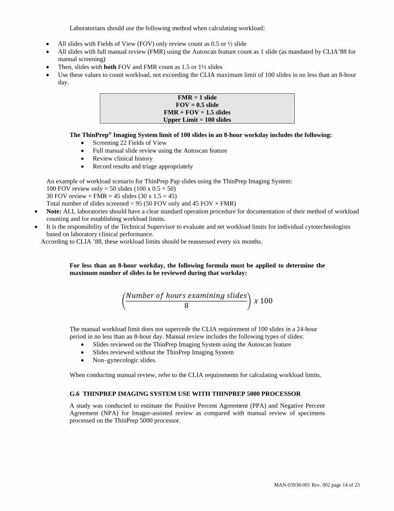
Laboratorians should use the following method when calculating workload:
All slides with Fields of View (FOV) only review count as 0.5 or ½ slide All slides with full manual review (FMR) using the Autoscan feature count as 1 slide (as mandated by CLIA’88 for
manual screening) Then, slides with both FOV and FMR count as 1.5 or 1½ slides Use these values to count workload, not exceeding the CLIA maximum limit of 100 slides in no less than an 8-hour
day.
FMR = 1 slide FOV = 0.5 slide
FMR + FOV = 1.5 slides Upper Limit = 100 slides
The ThinPrep® Imaging System limit of 100 slides in an 8-hour workday includes the following:
Screening 22 Fields of View Full manual slide review using the Autoscan feature Review clinical history Record results and triage appropriately
An example of workload scenario for ThinPrep Pap slides using the ThinPrep Imaging System: 100 FOV review only = 50 slides (100 x 0.5 = 50) 30 FOV review + FMR = 45 slides (30 x 1.5 = 45) Total number of slides screened = 95 (50 FOV only and 45 FOV + FMR)
Note: ALL laboratories should have a clear standard operation procedure for documentation of their method of workload counting and for establishing workload limits.
It is the responsibility of the Technical Supervisor to evaluate and set workload limits for individual cytotechnologists based on laboratory clinical performance.
According to CLIA ’88, these workload limits should be reassessed every six months.
For less than an 8-hour workday, the following formula must be applied to determine the maximum number of slides to be reviewed during that workday:
8
100
The manual workload limit does not supercede the CLIA requirement of 100 slides in a 24-hour period in no less than an 8-hour day. Manual review includes the following types of slides:
Slides reviewed on the ThinPrep Imaging System using the Autoscan feature Slides reviewed without the ThinPrep Imaging System Non–gynecologic slides.
When conducting manual review, refer to the CLIA requirements for calculating workload limits.
G.6 THINPREP IMAGING SYSTEM USE WITH THINPREP 5000 PROCESSOR
A study was conducted to estimate the Positive Percent Agreement (PPA) and Negative Percent Agreement (NPA) for Imager-assisted review as compared with manual review of specimens processed on the ThinPrep 5000 processor.

MAN-03938-001 Rev. 002 page 15 of 23
Clinical Study Design The study was a prospective, multi-center, blinded evaluation of ThinPrep slides of known diagnoses generated from residual cytological specimens which were prepared, reviewed and adjudicated in a previous study.
One thousand two hundred sixty (1260) slides were prepared on a ThinPrep 5000 processor and were reviewed independently by a Cytotechnologist and confirmed by a Pathologist. All cytologic diagnoses were determined in accordance with the Bethesda System 2001 criteria for all slides1. The study was conducted at Hologic, Inc., Marlborough, MA and at two external laboratories in the United States.
Table 16: Laboratory Imager-Assisted Review Diagnosis vs. Laboratory Manual Review Diagnosis by one Pair of Cytotechnologist/Pathologist (Combined Sites)
Lab Imager-Assisted Review Diagnosis
Lab Manual Review Diagnosis
UNSAT NILM ASC-US AGUS LSIL ASC-H HSIL Cancer Total
UNSAT 30 10 2 0 1 0 0 0 43
NILM 10 620 36 1 5 5 3 1 681
ASC-US 3 40 35 10 8 1 2 0 99
AGUS 0 10 28 127 8 0 8 0 181
LSIL 0 4 9 4 14 2 13 0 46
ASC-H 2 2 1 0 1 3 1 2 12
HSIL 1 3 6 15 24 2 111 5 167
Cancer 1 0 0 0 1 1 7 21 31
Total 47 689 117 157 62 14 145 29 1260
Reference Diagnosis by Adjudication Review
All slides were subject to an adjudication review. Adjudication was done at a facility that was not one of the study sites conducting the study. Slides for adjudication were evenly divided between three (3) adjudication panels each consisting of one (1) Cytotechnologist and three (3) independent Pathologists. Each adjudication panel was blinded to the original review diagnosis for all slides and each independent Pathologist within each panel was also blinded to other adjudicator’s diagnoses for all slides. Adjudication consensus agreement was obtained for each slide reviewed. Consensus agreement was achieved when at least two (2) of the three (3) Pathologists from a panel rendered an identical diagnosis. In cases where consensus agreement was not achieved the panel members were brought together at a multi-head microscope to review the slides together and come to a consensus diagnosis.
In the study, there were 18 Cancer, 92 HSIL, 37 ASC-H, 180 LSIL, 18 AGUS, 122 ASC-US, 770 NILM, and 23 UNSAT specimens. Clinical sensitivity and specificity (e.g., with reference to a histological diagnosis) cannot be measured in this study which relied on cytological examination alone. Instead, laboratory positive and negative diagnoses by both methods, Imager-assisted and manual review, for the specimens with Reference Diagnosis of ASC-US+ (combined ASC-US, AGUS, LSIL, ASC-H, HSIL, and Cancer), LSIL+ (combined LSIL, ASC-H, HSIL, and Cancer), ASC-H+ (combined ASC-H, HSIL, and Cancer) and HSIL+ (combined HSIL and Cancer) were compared.

MAN-03938-001 Rev. 002 page 16 of 23
Clinical Study Results Tables 17 through 20 present the comparison of Laboratory true positive and negative rates for ASC-US+, LSIL+, ASC-H+, and HSIL+.
Table 17: Laboratory Imager-Assisted Review Results vs. Laboratory Manual Review Results for the Specimens with Reference Diagnosis of ASC-US+
In the study, there were 467 specimens with Reference Diagnosis of ASC-US+ (combined ASC-US, AGUS, LSIL, ASC-H, HSIL, and Cancer) and 770 specimens with Reference Diagnosis of NILM.
In this table, “Positive” means ASC-US+ or UNSAT, and “Negative” means NILM. All percentages are rounded to the nearest 0.1%.
ASC-US+ Positive Percent Agreement Negative Percent Agreement
Lab CT/ Pathologist
Imager-Assisted Manual Difference Imager-Assisted Manual Difference
(95% CI) (95% CI) (95% CI) (95% CI) (95% CI) (95% CI)
93.8% 95.1% -1.3% 84.4% 81.9% 2.5%
#1 (287/306) (291/306) (-4/306) (434/514) (421/514) (13/514)
(90.5% to 96.0%) (92.1% to 97.0%) (-4.2% to 1.5%) (81.0% to 87.3%) (78.3% to 85.0%) (-0.2% to 5.3%)
91.6% 92.3% -0.6% 84.8% 85.2% -0.4%
#2 (428/467) (431/467) (-3/467) (653/770) (656/770) (-3/770)
(88.8% to 93.8%) (89.5% to 94.4%) (-3.3% to 1.9%) (82.1% to 87.2%) (82.5% to 87.5%) (-2.9% to 2.1%)
91.9% 91.4% 0.4% 83.0% 83.4% -0.4%
#3 (429/467) (427/467) (2/467) (639/770) (642/770) (-3/770)
(89.0% to 94.0%) (88.5% to 93.6%) (-2.1% to 3.0%) (80.2% to 85.5%) (80.6% to 85.8%) (-2.9% to 2.1%)
92.3% 92.7% -0.4% 84.0% 83.7% 0.3%
Combined (1144/1240) (1149/1240) (-5/1240) (1726/2054) (1719/2054) (7/2054)
(90.6% to 93.6%) (91.1% to 94.0%) (-1.9% to 1.1%) (82.4% to 85.6%) (82.0% to 85.2%) (-1.1% to 1.8%)
MAN-03938-001 Rev. 002 page 17 of 23
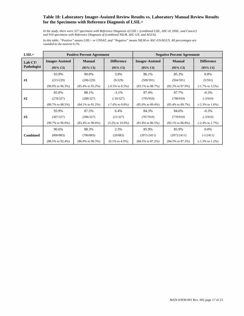
Table 18: Laboratory Imager-Assisted Review Results vs. Laboratory Manual Review Results for the Specimens with Reference Diagnosis of LSIL+
In the study, there were 327 specimens with Reference Diagnosis of LSIL+ (combined LSIL, ASC-H, HSIL, and Cancer) and 910 specimens with Reference Diagnosis of (combined NILM, ASC-US, and AGUS).
In this table, “Positive” means LSIL+ or UNSAT, and “Negative” means NILM or ASC-US/AGUS. All percentages are rounded to the nearest 0.1%.
LSIL+ Positive Percent Agreement Negative Percent Agreement
Lab CT/ Pathologist
Imager-Assisted Manual Difference Imager-Assisted Manual Difference
(95% CI) (95% CI) (95% CI) (95% CI) (95% CI) (95% CI)
93.9% 90.0% 3.9% 86.1% 85.3% 0.8%
#1 (215/229) (206/229) (9/229) (509/591) (504/591) (5/591)
(90.0% to 96.3%) (85.4% to 93.2%) (-0.5% to 8.5%) (83.1% to 88.7%) (82.2% to 87.9%) (-1.7% to 3.5%)
85.0% 88.1% -3.1% 87.4% 87.7% -0.3%
#2 (278/327) (288/327) (-10/327) (795/910) (798/910) (-3/910)
(80.7% to 88.5%) (84.1% to 91.2%) (-7.0% to 0.8%) (85.0% to 89.4%) (85.4% to 89.7%) (-2.3% to 1.6%)
93.9% 87.5% 6.4% 84.3% 84.6% -0.3%
#3 (307/327) (286/327) (21/327) (767/910) (770/910) (-3/910)
(90.7% to 96.0%) (83.4% to 90.6%) (3.2% to 10.0%) (81.8% to 86.5%) (82.1% to 86.8%) (-2.4% to 1.7%)
90.6% 88.3% 2.3% 85.9% 85.9% 0.0%
Combined (800/883) (780/883) (20/883) (2071/2411) (2072/2411) (-1/2411)
(88.5% to 92.4%) (86.0% to 90.3%) (0.1% to 4.5%) (84.5% to 87.2%) (84.5% to 87.3%) (-1.3% to 1.2%)

MAN-03938-001 Rev. 002 page 18 of 23
Table 19: Laboratory Imager-Assisted Review Results vs. Laboratory Manual Review Results for the Specimens with Reference Diagnosis of ASC-H+
In the study, there were 147 specimens with Reference Diagnosis of ASC-H+ (combined ASC-H, HSIL, and Cancer) and 1,090 specimens with Reference Diagnosis of (combined NILM, ASC-US/AGUS, and LSIL).
In this table, “Positive” means ASC-H+ or UNSAT, and “Negative” means NILM, ASC-US/AGUS, or LSIL. All percentages are rounded to the nearest 0.1%.
ASC-H+ Positive Percent Agreement Negative Percent Agreement
Lab CT/ Pathologist
Imaged Manual Difference Imaged Manual Difference
(95% CI) (95% CI) (95% CI) (95% CI) (95% CI) (95% CI)
93.7% 88.3% 5.4% 86.7% 86.7% 0.0%
#1 (104/111) (98/111) (6/111) (615/709) (615/709) (0/709)
(87.6% to 96.9%) (81.0% to 93.0%) (-0.6% to 12.0%) (84.0% to 89.0%) (84.0% to 89.0%) (-2.2% to 2.2%)
86.4% 86.4% 0.0% 89.4% 89.4% -0.1%
#2 (127/147) (127/147) (0/147) (974/1090) (975/1090) (-1/1090)
(79.9% to 91.0%) (79.9% to 91.0%) (-6.8% to 6.8%) (87.4% to 91.1%) (87.5% to 91.1%) (-1.8% to 1.6%)
95.2% 89.8% 5.4% 88.2% 87.4% 0.7%
#3 (140/147) (132/147) (8/147) (961/1090) (953/1090) (8/1090)
(90.5% to 97.7%) (83.8% to 93.7%) (-0.1% to 11.4%) (86.1% to 90.0%) (85.3% to 89.3%) (-1.0% to 2.5%)
91.6% 88.1% 3.5% 88.3% 88.0% 0.2%
Combined (371/405) (357/405) (14/405) (2550/2889) (2543/2889) (7/2889)
(88.5% to 93.9%) (84.6% to 90.9%) (0.0% to 7.0%) (87.0% to 89.4%) (86.8% to 89.2%) (-0.8% to 1.3%)

MAN-03938-001 Rev. 002 page 19 of 23
Table 20: Laboratory Imager-Assisted Review Results vs. Laboratory Manual Review Results for the Specimens with Reference Diagnosis of HSIL+
In the study, there were 110 specimens with Reference Diagnosis of HSIL+ (combined HSIL and Cancer) and 1,127 specimens with Reference Diagnosis of (combined NILM, ASC-US/AGUS, LSIL, and ASC-H).
In this table, “Positive” means HSIL+ or UNSAT, and “Negative” means NILM, ASC-US/AGUS, LSIL, or ASC-H. All percentages are rounded to the nearest 0.1%.
HSIL+ Positive Percent Agreement Negative Percent Agreement
Lab CT/ Pathologist
Imaged Manual Difference Imaged Manual Difference
(95% CI) (95% CI) (95% CI) (95% CI) (95% CI) (95% CI)
90.7% 80.2% 10.5% 86.8% 89.1% -2.3%
#1 (78/86) (69/86) (9/86) (637/734) (654/734) (-17/734)
(82.7% to 95.2%) (70.6% to 87.3%) (2.9% to 18.8%) (84.1% to 89.0%) (86.6% to 91.2%) (-4.6% to -0.1%)
80.9% 74.5% 6.4% 92.1% 92.3% -0.2%
#2 (89/110) (82/110) (7/110) (1038/1127) (1040/1127) (-2/1127)
(72.6% to 87.2%) (65.7% to 81.8%) (-2.0% to 14.7%) (90.4% to 93.5%) (90.6% to 93.7%) (-1.7% to 1.4%)
90.9% 82.7% 8.2% 89.0% 89.7% -0.7%
#3 (100/110) (91/110) (9/110) (1003/1127) (1011/1127) (-8/1127)
(84.1% to 95.0%) (74.6% to 88.7%) (0.7% to 16.0%) (87.0% to 90.7%) (87.8% to 91.3%) (-2.4% to 0.9%)
87.3% 79.1% 8.2% 89.6% 90.5% -0.9%
Combined (267/306) (242/306) (25/306) (2678/2988) (2705/2988) (-27/2988)
(83.1% to 90.5%) (74.2% to 83.3%) (3.7% to 12.7%) (88.5% to 90.7%) (89.4% to 91.5%) (-1.9% to 0.1%)
In the study, there were 1.83% (23/1260) ThinPrep 5000 slides with UNSAT results by Adjudication.

MAN-03938-001 Rev. 002 page 20 of 23
Agreement among Laboratory Cytotechnologists/Pathologists The following tables indicate the extent to which the laboratory Cytotechnologists/Pathologists at a given site agreed amongst themselves on the diagnosis, comparing the Imager-assisted review to the manual review. Tables are provided for ASC-US+ and ASC-H+. Note that since one site had only two CT/Pathologist pairs, the three-way agreement analysis is available for just two sites, with 840 total specimens.
In Table 21 for ASC-H+, the number of specimens is shown for which various levels of agreement among the CTs occurred. Either all three CTs rated the slide as positive (ASC-H+), two out of three rated it positive, one out of three, or none of them.
Table 21: Laboratory Cytotechnologist/Pathologist Agreement, All Results, ASC-H+
Manual Review Three lab CTs have read the same slide
ASC-H+
Three CTs had
ASC-H+
Two CTs had ASC-H+
& one had <ASC-H
One CT had ASC-H+
& two had <ASC-H
Three CTs had <ASC-H
Totals
Imager-Assisted Review
Three lab CTs have read the
same slide
Three CTs had ASC-H+
91 23 8 0 122
Two CTs had ASC-H+ and one had <ASC-H
12 21 7 8 48
One CT had ASC-H+ and two had <ASC-H
3 12 16 11 42
Three CTs had <ASC-H
0 2 22 604 628
Totals 106 58 53 623 840
Manual Review
Three lab CTs have read the same slide
ASC-H+
Three or two CTs had ASC-H+
Three or two CTs had <ASC-H
Totals
Imager-Assisted Review
Three lab CTs have read the
same slide
Three or two CTs had ASC-H+
147 23 170
Three or two CTs had <ASC-H
17 653 670
Totals 164 676 840
MAN-03938-001 Rev. 002 page 21 of 23
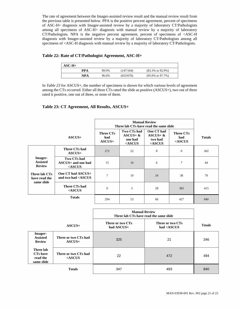
The rate of agreement between the Imager-assisted review result and the manual review result from the previous table is presented below. PPA is the positive percent agreement, percent of specimens of ASC-H+ diagnosis with Imager-assisted review by a majority of laboratory CT/Pathologists among all specimens of ASC-H+ diagnosis with manual review by a majority of laboratory CT/Pathologists. NPA is the negative percent agreement, percent of specimens of <ASC-H diagnosis with Imager-assisted review by a majority of laboratory CT/Pathologists among all specimens of <ASC-H diagnosis with manual review by a majority of laboratory CT/Pathologists.
Table 22: Rate of CT/Pathologist Agreement, ASC-H+
ASC-H+
PPA 89.0% (147/164) (83.3% to 92.9%)
NPA 96.6% (653/676) (95.0% to 97.7%)
In Table 23 for ASCUS+, the number of specimens is shown for which various levels of agreement among the CTs occurred. Either all three CTs rated the slide as positive (ASCUS+), two out of three rated it positive, one out of three, or none of them.
Table 23: CT Agreement, All Results, ASCUS+
Manual Review Three lab CTs have read the same slide
ASCUS+
Three CTs had
ASCUS+
Two CTs had ASCUS+ &
one had <ASCUS
One CT had ASCUS+ &
two had <ASCUS
Three CTs had
<ASCUS Totals
Imager-Assisted Review
Three lab CTs have read the
same slide
Three CTs had ASCUS+
272 22 8 0 302
Two CTs had ASCUS+ and one had
<ASCUS 15 16 6 7 44
One CT had ASCUS+ and two had <ASCUS
7 10 24 38 79
Three CTs had <ASCUS
0 5 28 382 415
Totals
294 53 66 427 840
Manual Review
Three lab CTs have read the same slide
ASCUS+
Three or two CTs had ASCUS+
Three or two CTs had <ASCUS
Totals
Imager-Assisted Review
Three lab CTs have read the
same slide
Three or two CTs had ASCUS+
325 21 346
Three or two CTs had <ASCUS
22 472 494
Totals 347 493 840

MAN-03938-001 Rev. 002 page 22 of 23
The rate of agreement between the Imager-assisted review result and the manual review result from the previous table is presented below. PPA is the positive percent agreement, percent of specimens of ASCUS+ diagnosis with Imager-assisted review by a majority of laboratory CT/Pathologists among all specimens of ASCUS+ diagnosis with manual review by a majority of laboratory CT/Pathologists. NPA is the negative percent agreement, percent of specimens of <ASCUS diagnosis with Imager-assisted review by a majority of laboratory CT/Pathologists among all specimens of <ASCUS diagnosis with manual review by a majority of laboratory CT/Pathologists.
Table 24: Rate of CT Agreement, ASCUS+
ASCUS+
PPA 93.7% (325/347) (90.6% to 95.8%)
NPA 95.7% (472/493) (93.6% to 97.2%)
H. Clinical Investigation Conclusions For all sites combined for ASCUS+, the improvement in sensitivity of the Imager Review
method over the Manual Review method is statistically significant. This increase is 6.4% with a 95% confidence interval of 2.6% to 10.0% for all sites combined. The differences in sensitivity varied among the sites from –2.8% to +14.4%. For LSIL+ and HSIL+ the sensitivity of the Imager Review method is equivalent to the Manual Review method.
For all sites combined for HSIL+, the improvement in specificity of the Imager Review method over the Manual Review method is statistically significant. This increase is 0.2% with a 95% confidence interval of 0.06% to 0.4% for all sites combined. The differences in specificity varied among the sites from –0.1% to +0.7%. For ASCUS+ and LSIL+ the specificity of the Imager Review method is equivalent to the Manual Review method.
Specimen adequacy can be determined using the method described in Bethesda System 2001 or by having the Cytotechnologist count the cells in the 22 fields of view presented by the Imager.
The workload limit for the ThinPrep Imaging System has been established at 200 slides in no less than an 8-hour workday. This workload limit of 200 slides includes the time spent for manual review of slides that is not to exceed 100 slides in an 8 hour workday.
For these clinical sites and these study populations, the data from the clinical trial and clinical support studies demonstrate that the use of the ThinPrep Imaging System to assist during primary screening of ThinPrep Pap Test slides for all cytologic interpretations, as defined by the Bethesda System, is safe and effective for the detection of cervical abnormalities. Performance may vary from site to site as a result of differences in patient populations and reading practices. As a result each laboratory using this device should employ quality assurance and control systems to ensure proper use and selection of appropriate workload limits.

MAN-03938-001 Rev. 002 page 23 of 23
I. Bibliography
1. Solomon D., Davey D, Kurman R, Moriarty A, O’Connor D, Prey M, Raab S, Sherman M, Wilbur D, Wright T, Young N, for the Forum Group Members and the 2001 Bethesda Workshop. The 2001 Bethesda System Terminology for Reporting Results of Cervical Cancer. JAMA. 2002;287:2114-2119.
2. Kurman RJ, Solomon D. The Bethesda System for Reporting Cervical/Vaginal Cytologic Diagnoses. Springer-Verlag 1994.
3. Schafer, J.L. Multiple imputation: a primer. Statistical Methods in Medical Research, 1999, 8:3-15.
4. National Cancer Institute. SEER Cancer Statistics Review 1973-1998. Available at: http://www.seer.cancer.gov. Accessed February 2002.
Hologic, Inc. 250 Campus Drive Marlborough, MA 01752 USA 1-800- 442-9892 www. hologic.com
AW-12515-001 Rev. 001
© 2015 Hologic, Inc. All rights reserved.

Table o
f Co
nten
ts Tab
le o
f C
on
ten
ts

CONTENTS
T a b l e o f C o n t e n t sContents
Chapter One
INTRODUCTION
SECTION A: Overview 1.1
SECTION B: The ThinPrep Imaging System Process 1.2
SECTION C: Specimen Preparation 1.5
SECTION D: Review Scope Manual+ Technical Specifications 1.6
SECTION E: Internal Quality Control 1.10
SECTION F: ThinPrep Review Scope Manual+ Hazards 1.11
SECTION G: Disposal 1.14
Chapter Two
INSTALLATION
SECTION A: General 2.1
SECTION B: Action Upon Delivery 2.1
SECTION C: Preparation Prior to Installation 2.1
SECTION D: Moving the Review Scope Manual+ 2.2
SECTION E: Connecting Review Scope Manual+ Components 2.4
SECTION F: Power On the Review Scope Manual+ 2.8
SECTION G: User Preferences 2.10
SECTION H: Storage and Handling - Post Installation 2.10
SECTION I: System Shutdown 2.10
Chapter Three
USER INTERFACE
SECTION A: Overview 3.1
SECTION B: Startup 3.3
SECTION C: Administrative Options 3.4
SECTION D: Login 3.9
SECTION E: Main Menu 3.10
SECTION F: User Preferences 3.11
SECTION G: Start 3.21
ThinPrep® Review Scope Manual+ Operator’s Manual i

CONTENTS
Chapter Four
OPERATION
SECTION A: Overview 4.1
SECTION B: Materials Required Prior to Operation 4.4
SECTION C: Using the Touch Screen and Review Controls 4.4
SECTION D: Slide Review 4.7
SECTION E: Review of Slides Not for Use with ThinPrep Imaging 4.18
Chapter Five
MAINTENANCE
SECTION A: General Cleaning 5.1
SECTION B: Koehler Alignment 5.2
Chapter Six
TROUBLESHOOTING
SECTION A: Invalid Slide ID 6.1
SECTION B: Failed to Read Slide ID 6.1
SECTION C: Slide ID Mismatch While Completing the Review 6.3
SECTION D: Error Handling 6.4
Chapter Seven
SERVICE INFORMATION 7.1
Chapter Eight
ORDERING INFORMATION 8.1
Index
ii ThinPrep® Review Scope Manual+ Operator’s Manual

1. Intro
du
ction
1. In
tro
du
ctio
n
1INTRODUCTION
C h a p t e r O n e
Introduction
OVERVIEW
The ThinPrep® Review Scope Manual+ is an automated microscope to be used by a cytotechnologist (CT) to screen ThinPrep Pap Test slides that have been imaged by a ThinPrep Image Processor. The microscope is a quality laboratory microscope enhanced with automated features that facilitate review of the slide. The CT views the slide and by means of automatic stage movement, is presented with fields of view containing objects of interest identified by the Imaging System. Using a touch screen monitor and hand controls, the CT is able to screen the slide and target areas for physical marking after the review. The Review Scope Manual+ is networked to the Imaging System and at review, slide data is retrieved from a slide database maintained by the Imaging System. At the con-clusion of a slide review, the slide data is updated in the database.
The Review Scope Manual+ also has the ability to act as a conventional microscope when not used in conjunction with ThinPrep imaging.
The Review Scope Manual+ consists of:
The Microscope, a customized microscope with internal camera for location of slide fiducial marks, slide ID reader, automated stage, hand controls and adjustable touch screen user interface.
Controller, which controls the electromechanical system.
Computer that hosts the system application.
SECTION
A
ThinPrep® Review Scope Manual+ Operator’s Manual 1.1
INTRODUCTION1
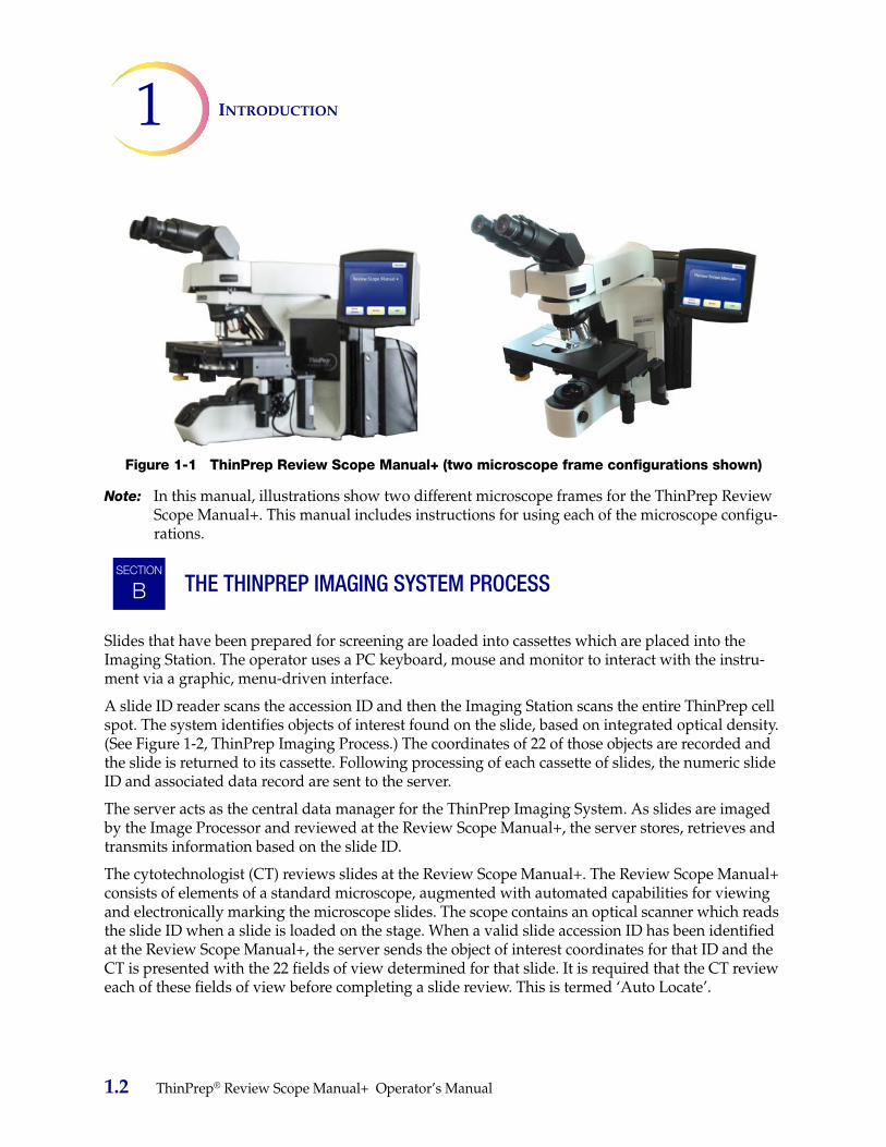
Figure 1-1 ThinPrep Review Scope Manual+ (two microscope frame configurations shown)
Note: In this manual, illustrations show two different microscope frames for the ThinPrep Review Scope Manual+. This manual includes instructions for using each of the microscope configu-rations.
THE THINPREP IMAGING SYSTEM PROCESS
Slides that have been prepared for screening are loaded into cassettes which are placed into the Imaging Station. The operator uses a PC keyboard, mouse and monitor to interact with the instru-ment via a graphic, menu-driven interface.
A slide ID reader scans the accession ID and then the Imaging Station scans the entire ThinPrep cell spot. The system identifies objects of interest found on the slide, based on integrated optical density. (See Figure 1-2, ThinPrep Imaging Process.) The coordinates of 22 of those objects are recorded and the slide is returned to its cassette. Following processing of each cassette of slides, the numeric slide ID and associated data record are sent to the server.
The server acts as the central data manager for the ThinPrep Imaging System. As slides are imaged by the Image Processor and reviewed at the Review Scope Manual+, the server stores, retrieves and transmits information based on the slide ID.
The cytotechnologist (CT) reviews slides at the Review Scope Manual+. The Review Scope Manual+ consists of elements of a standard microscope, augmented with automated capabilities for viewing and electronically marking the microscope slides. The scope contains an optical scanner which reads the slide ID when a slide is loaded on the stage. When a valid slide accession ID has been identified at the Review Scope Manual+, the server sends the object of interest coordinates for that ID and the CT is presented with the 22 fields of view determined for that slide. It is required that the CT review each of these fields of view before completing a slide review. This is termed ‘Auto Locate’.
SECTION
B
1.2 ThinPrep® Review Scope Manual+ Operator’s Manual
1INTRODUCTION
Each field of view is presented to the CT at 10X magnification. The nosepiece also has 4X and 40X objectives, which the CT can switch to manually. Before the next field of view can be presented, the Review Scope Manual+ senses if the 10X objective is engaged in the light path. If not, the system prompts the CT to return the magnification to 10X. This is to ensure that all 22 fields of view will have been presented to the CT at 10X magnification.
Note: The object of interest is typically placed in the center of the field of view, however the CT must screen the entire field of each of the 22 fields of view presented.
During slide review, the CT has the option to electronically mark an area for subsequent review and/or physical marking. One or more electronic marks enforces a review of the entire cell spot, not just the 22 fields of interest. This is termed ‘Auto Scan.’
During Auto Scan review, the CT may add or delete electronic marks. Physical marking of the slide coverslip with a pen is done manually by the CT.
The CT has the option to control the position of the stage manually, which provides complete free-dom to move any portion of the cell spot into the field of view for examination.
ThinPrep® Review Scope Manual+ Operator’s Manual 1.3

INTRODUCTION1
Figure 1-2 ThinPrep Imaging Process
A prepared ThinPrep slide is loaded into a slide cassette, which is loaded into the Image Processing Station.
The cell spot is imaged.
Slide review by the cytotechnologist
Normal slide
The slide imaging system scans the entire cell spot. The system identifies objects of interest found on the slide.
The coordinates of 22 objects of interest with the highest integrated optical density will be stored in the computer’s database.
During Auto Locate the system pres-ents the 22 selected fields of view in geographic order to the cytotechnol-ogist.Suspect cells may be electronically marked by the CT and a review of the entire cell spot is enforced. The slide is manually marked by the CT.At completion, the slide data is updated with the location of any marked areas as well as information on the review session.
Abnormal slides are reviewed by a cytopathologist for interpretation and diagnosis.
1.4 ThinPrep® Review Scope Manual+ Operator’s Manual
1INTRODUCTION
SPECIMEN PREPARATION
Specimens for the ThinPrep® Pap Test cytology slide are collected by a clinician, then immersed and rinsed in a PreservCyt® Solution sample vial. The sample is then capped, labeled and sent to a labo-ratory equipped with a ThinPrep Processor. The samples are processed on ThinPrep Imaging System slides. After being processed, the slides are stained with ThinPrep Stain.
Please refer to the operator’s manuals of these instruments and stain for more information regarding preparation and processing of ThinPrep slides.
Specimen HandlingThe ThinPrep slides are stored, transported and handled the same as conventional cytology slides. Please refer to your laboratory guidelines for specimen handling.
SECTION
C
ThinPrep® Review Scope Manual+ Operator’s Manual 1.5

INTRODUCTION1
2
t
REVIEW SCOPE MANUAL+ TECHNICAL SPECIFICATIONS
Overview of Components
Figure 1-3 Review Scope Manual+ Components (two microscope configurations shown)
SECTION
D
16 15
11110
987
1
6
2
5
14
3
1714
10
9
8
7
23
456
1
16 15
121113
13
4X objective (red stripe)
10X objective (yellow stripe)
40X objective (blue stripe)
10X objective position sensorRevolving nosepiece
1. Eyepieces
2. Binocular tube
3. Revolving nosepiece (4X, 10X, 40X, plus position sen-sor)
4. Motorized stage
5. Condenser (under stage)
6. Collector
7. Coarse/fine focus knob (on left side of microscope)
8. Light intensity adjustment knob
9. X,Y axis stage control knobs (stage control)
10. Microscope power switch (on back left of microscope with black side panel)
11. Allen screwdriver (near the controller on the back of the microscope with the black side panel)
12. Computer
13. Touch screen interface
14. Computer power switch
15. Controller
16. Review control
17. Note:The “SET” button on the microscope with the black side panel, shown on the left, is noused. The “LIM” button is also not used and will illuminate, with no effect, if pushed.
1.6 ThinPrep® Review Scope Manual+ Operator’s Manual

1INTRODUCTION
Dimensions
Figure 1-4 Review Scope Manual+ Dimensions (two microscope configurations shown)
22 in.559 mm
26.75 in.680 mm
18 in.457 mm
Microscope configuration with the grey side panel
Microscope configuration with the black side panel
18 in.457 mm
24 in.609 mm
28 in.711 mm
ThinPrep® Review Scope Manual+ Operator’s Manual 1.7

INTRODUCTION1
ThinPrep® Microscope Slide for Use with the Imaging SystemThe ThinPrep microscope slide is used by the ThinPrep Processor in preparing the patient slide. The slide utilizes fiducial marks, or fixed reference points, which are permanently printed features on the slide that are used to register the slide position on the stage. A coordinate system is based on the fidu-cial marks, for locating objects of interest on the cell spot.Figure 1-5 ThinPrep Microscope Slide
Slide Labeling FormatsThe formats that the optical scanner on the Review Scope Manual+ can read for the accession ID on the slide label are configured on the Imaging System server. Refer to the Image Processor Operator's Manual for specifications for slide label formats.
WeightThe Review Scope Manual+ including the microscope, controller, computer and all cabling weighs approximately 70 lbs. (32 kg).
Environmental
Operating temperature range16°C to 32°C (60°F to 90°F)
Non-operating temperature range-29°C to 50°C (-20°F to 122°F)
Operating humidity range20% to 80% relative humidity, non-condensing
Non-operating humidity range15% to 95% relative humidity, non-condensing
Pollution Degree II, in accordance with IEC 61010-1
14-digit numeric accession ID(OCR label format shown)
Fiducial mark
Fiducial mark
Frosted portion of the slide
Cell spot - contains patient sample cells
Fiducial mark
1.8 ThinPrep® Review Scope Manual+ Operator’s Manual
1INTRODUCTION
Category II. The ThinPrep Review Scope Manual+ is for indoor use only in an office or a clean labo-ratory environment.
Altitude0 meters (sea level) to 2000 meters
Atmospheric pressure1100 millibar to 500 millibar
Sound levelsMaximum A-weighted sound pressure level at the operator’s position and at a bystander’s position is 66.2 dBA.
Power
Voltage100–120V~/220-240V~ single phase, 50–60 Hz ± 5%
PowerLess than 150 Watts (512 Btu/hour) for the microscope and controller, not including the computer
Power cablesMaximum length must be less than 3 m (9.8 ft.).
FusingTwo 3.15A, 250 VAC, time delay, low break capacity (instrument)
Note: Fuses are not user-accessible and are not intended to be changed by users. Contact Technical Support if the instrument does not operate. Do not remove any covers on the components.
Connections to External CircuitsThe external connections from the Review Scope Manual+ to the PC are PELV (Protected Extra Low Voltage) as defined by IEC 61140. Outputs of other devices connected to the PC should also be PELV or SELV (Safety Extra Low Voltage). Only devices approved for safety by an appropriate agency should be connected to the PC.
Note: The computer manufacturer provides documentation for the PC. Refer to that for technical specifications. Do not discard.
Safety, EMI and EMC StandardsThe ThinPrep Review Scope Manual+ has been tested and certified by a U.S. nationally recognized testing Laboratory (NRTL) to comply with current Safety, Electro-Magnetic Interference (EMI) and Electro-Magnetic Compatibility (EMC) standards. Refer to the model/rating label, located on the rear of the controller, to see the safety certification markings. This equipment meets the IEC 61010-2-101 particular safety requirements for IVD equipment.
ThinPrep® Review Scope Manual+ Operator’s Manual 1.9
INTRODUCTION1
This equipment meets the emission and immunity requirements of IEC 61326-2-6. This equipment has been tested and found to comply to CISPR 11 Class A emission limits.
In a domestic environment it may cause radio interference, in which case, measures to mitigate the interference may be necessary. The electromagnetic environment should be evaluated prior to opera-tion of the equipment. Do not use this device in close proximity to sources of strong electromagnetic radiation (e.g., unshielded RF sources), as these may interfere with the proper operation.
This product is in vitro diagnostic (IVD) medical equipment.
This product contains a device classified per EN 60825-1: 1994, Issue 2, June 1997 as a Class I LED product.
INTERNAL QUALITY CONTROL
Power On Self Test (POST)At the time the Review Scope Manual+ is powered on, the system goes through a self-diagnostic test. All electrical, mechanical and software systems are tested to confirm each performs properly. The operator is alerted to any malfunction via a message on the user interface. If the system does not function or there are persistent errors, contact Hologic Technical Support (refer to Chapter 7, Service Information).
Post Scan Functional ChecksAt the completion of slide review, the instrument will do functional checks to ensure integrity of the data gathered during review. The operator is alerted to any malfunction via a message on the user interface. If the system does not function or there are persistent errors, contact Hologic Technical Support (refer to Chapter 7, Service Information).
SECTION
E
1.10 ThinPrep® Review Scope Manual+ Operator’s Manual

1INTRODUCTION
THINPREP REVIEW SCOPE MANUAL+ HAZARDS
The Review Scope Manual+ is intended to be operated in the manner specified in this manual. Be sure to review and understand the information listed below in order to avoid harm to operators and/ or damage to the instrument. Do not operate the instrument with a cover on it.
If this equipment is used in a manner not specified by the manufacturer, then the protection provided by the equipment may be impaired.
Warnings, Cautions and NotesThe terms WARNING, CAUTION and Note have specific meanings in this manual.
• A WARNING advises against certain actions or situations that could result in personal injury or death.
• A CAUTION advises against actions or situations that could damage equipment, produce inaccurate data or invalidate a procedure, although personal injury is unlikely.
• A Note provides useful information within the context of the instructions being provided.
SECTION
F
ThinPrep® Review Scope Manual+ Operator’s Manual 1.11

INTRODUCTION1
Symbols Used on the InstrumentThe following symbols are used on this instrument:
Figure 1-6 Symbols Used on the Instrument
1
2
3
4
5
6
Attention - refer to accompanying documents
Fuse (Not user-accessible)
Waste Electrical and Electronic Equipment Do not dispose in municipal wasteContact Hologic for disposal of the instrument
In vitro diagnostic medical device
Serial number
Manufacturer
Authorized representative in the European Community
On (Power switch on the microscope)
Off (Power switch on the microscope)
Lamp intensity adjustment
Standby power (computer)
USB port icon (computer)
Ethernet port icon (computer)
Monitor display (computer)
1.12 ThinPrep® Review Scope Manual+ Operator’s Manual

1INTRODUCTION
Location of Labels
Figure 1-7 Location of Labels on the Instrument
PC serial number on top (not shown)
USB port
Standby power
Ethernet port
USB ports
Front and Rear of Computer
(Note: The number and exact location of ports may be different, depending on the PC model you have.)
Display port
Instrument part number label
Instrument serial number label
Model/rating label (includes these marks)
Rear of Instrument (PC removed for clarity.)
ThinPrep® Review Scope Manual+ Operator’s Manual 1.13

INTRODUCTION1
Warnings Used in this Manual
WARNING: Service Installation Only. This instrument is to be installed by trained Hologic person-nel only.
WARNING: Grounded Outlet. To ensure safe operation of the instruments use a three-wire grounded outlet.
WARNING: Glass. The instrument uses microscope slides, which have sharp edges. In addition, the slides may be broken in their storage packaging or on the instrument. Use caution when han-dling glass slides and when cleaning the instrument.
DISPOSAL
Disposal of consumablesBroken glass. Dispose of in a sharps container.
Disposal of the devicePlease contact Hologic Service. (Refer to Chapter 7, Service Information.)
Do not dispose in municipal waste.
Hologic, Inc.250 Campus DriveMarlborough, MA 01752 USATel: 1-800-442-9892
1-508-263-2900Fax: 1-508-229-2795Web: www.hologic.com
SECTION
G
1.14 ThinPrep® Review Scope Manual+ Operator’s Manual

2. Installatio
n2.
Inst
alla
tio
n

2INSTALLATION
C h a p t e r T w o
Installation
WARNING: Service Installation Only
GENERAL
The ThinPrep® Review Scope Manual+ must be installed by Hologic service personnel. When installation is complete, Hologic personnel trains the operator(s), using the operator’s manual as the training guide.
ACTION UPON DELIVERY
Remove and read the Operating Instructions Prior to Installation sheet attached to the packing carton.
Inspect the packing cartons for damage. Report any damage immediately to the shipper and/or Hologic Technical Support as soon as possible. (Refer to Chapter 7, Service Information.)
Leave the instrument in the packing cartons for Hologic service installation.
Store the instrument in a suitable environment until installation (cool, dry, vibration-free area).
Note: The computer manufacturer provides documentation for the PC. Refer to that for technical specifications. Do not discard.
PREPARATION PRIOR TO INSTALLATION
Pre-Installation Site AssessmentA pre-installation site assessment is performed by Hologic service personnel. Be sure to have pre-pared any and all site configuration requirements as instructed by the service personnel.
The Review Scope Manual+ will require two outlets to power the instrument. Make sure there is ade-quate electrical supply within 2 meters of the instrument. It must be plugged into a three-prong grounded outlet. Disconnection from the power supply source is by removal of the power cord.
Note: Do not position the instrument so that it is difficult to disconnect the power cords.
SECTION
A
SECTION
B
SECTION
C
ThinPrep® Review Scope Manual+ Operator’s Manual 2.1
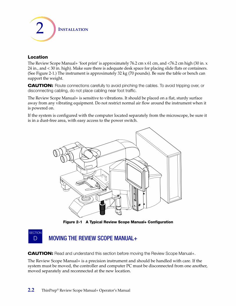
INSTALLATION2
LocationThe Review Scope Manual+ ‘foot print’ is approximately 76.2 cm x 61 cm, and <76.2 cm high (30 in. x 24 in., and < 30 in. high). Make sure there is adequate desk space for placing slide flats or containers. (See Figure 2-1.) The instrument is approximately 32 kg (70 pounds). Be sure the table or bench can support the weight.
CAUTION: Route connections carefully to avoid pinching the cables. To avoid tripping over, or disconnecting cabling, do not place cabling near foot traffic.
The Review Scope Manual+ is sensitive to vibrations. It should be placed on a flat, sturdy surface away from any vibrating equipment. Do not restrict normal air flow around the instrument when it is powered on.
If the system is configured with the computer located separately from the microscope, be sure it is in a dust-free area, with easy access to the power switch.
Figure 2-1 A Typical Review Scope Manual+ Configuration
MOVING THE REVIEW SCOPE MANUAL+
CAUTION: Read and understand this section before moving the Review Scope Manual+.
The Review Scope Manual+ is a precision instrument and should be handled with care. If the system must be moved, the controller and computer PC must be disconnected from one another, moved separately and reconnected at the new location.
SECTION
D
2.2 ThinPrep® Review Scope Manual+ Operator’s Manual

2INSTALLATION
The microscope and controller are mechanically and electronically connected and should NOT be separated. The cabling between the controller and the computer may be disconnected and reconnected. See Figure 2-2.
Before disconnecting any of the components, be sure to observe how they are originally connected. See Figure 2-2. The connectors must go in the exact ports specified
Figure 2-2 Review Scope Manual+ Interconnections
Note: The computer may be set up to face either side, or with the use of the extension cable set, it can be placed further away from the microscope and controller. The final configuration may look slightly different than Figure 2-2. The cable connections to the computer ports remain the same.
Computer AC power cord
1 (USB cable)
2 (USB cable)
Ethernet connection
VGA (for touch screen)
Firewire (for internal camera)
4 (USB cable)
ThinPrep® Review Scope Manual+ Operator’s Manual 2.3

INSTALLATION2
The microscope should be grasped and lifted by the frame housing. Lifting the instrument by the motorized stage will cause damage to the microscope and may render it inoperable. Grasp the frame behind the nosepiece turret as shown in Figure 2-3.CAUTION: The instrument weighs 32 kg (70 lbs.) and should be moved by at least two people.
CAUTION: Lifting the instrument by the motorized stage will cause damage to the microscope and may render it inoperable.
Figure 2-3 Moving the Review Scope Manual+ (two microscope frame configurations shown)
CONNECTING REVIEW SCOPE MANUAL+ COMPONENTS
The ThinPrep Review Scope Manual+ components must be fully assembled before turning on the power and using the instrument. Hologic service personnel will assemble the instrument:
• Controller
• Computer
• Microscope
• Assemble spacers, trinocular head (optional telescoping head or riser)
• Eyepieces
• Objectives
• User interface touch screen and mounting rail
Controller - controls the electromechanical subsystem.
SECTION
E
2.4 ThinPrep® Review Scope Manual+ Operator’s Manual

2INSTALLATION
®
Computer - hosts the system application.
Microscope - a customized microscope with internal camera for locating slide fiducial marks, slide ID camera, automated stage, stage controls and review control.
The trinocular head - a tilting binocular observation tube and a fixed, straight tube for the fiducial mark camera. The light path and camera focus have been optimized by placement of spacers in the assembly of the optical components. Do not add or remove spacers or risers.
One ocular has a diopter adjustment ring to provide common focus capability.
If an optional telescoping head is being used, be sure to use the specific riser that Hologic supplies.
If the optional riser is being used, do not use it in conjunction with the telescoping head. Use one or the other, but not both.
CAUTION: Only use Hologic-supplied eyepieces and objective lenses. DO NOT substitute eye-pieces or objectives.
Eyepieces - 10X magnification with a field size of 22 mm.
Objectives - 4X, 10X and 40X objectives are mounted on the revolving nosepiece at production. They are specifically compatible with the supplied eyepieces.
The other object in the nosepiece is the magnetic 10X position sensor. It must not be removed.
An optional 20X objective is available. (Refer to Chapter 8, Ordering Information.) It can be installed by the operator. If the 20X objective is installed, the objectives should be positioned as shown in Figure 2-4.
Figure 2-4 Positions of Objectives in the Nosepiece
MAG Open
40X
10X
4X
MAG
10X
4X
40X
20X
Front Front
Magnetic 10X position sensor. Do not move.
Standard Configuration for 4X, 10X and 40X
Optional Configuration for 4X, 10X, 20X and 40X
ThinPrep Review Scope Manual+ Operator’s Manual 2.5

INSTALLATION2
User interface touch screen and mounting rail - the touch screen height can be adjusted by moving the screen up or down along the mounting rail. The tilt and rotational angle of the screen may be adjusted by loosening the adjustment knobs, changing the tilt and rotation and then tightening each knob.
The network connection (see Figure 1-7) connects the Review Scope Manual+ to a networking device, enabling communication to the ThinPrep Imaging System server. Refer to the Image Proces-sor Operator's Manual for networking restrictions and requirements.
Note: It is the responsibility of the customer to purchase and install the necessary quantities and lengths of Ethernet cable required for networking the Review Scope Manual+ to the Imaging System. Installation configuration should be planned prior to instrument installation.
2.6 ThinPrep® Review Scope Manual+ Operator’s Manual
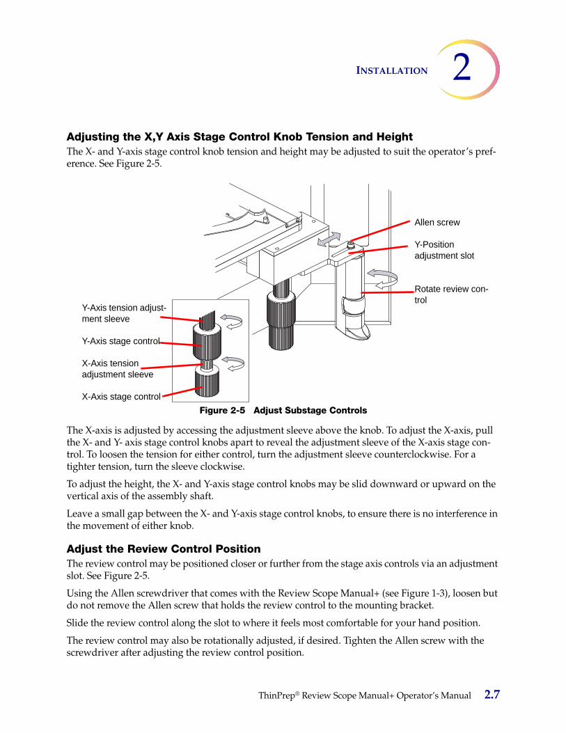
2INSTALLATION
Adjusting the X,Y Axis Stage Control Knob Tension and HeightThe X- and Y-axis stage control knob tension and height may be adjusted to suit the operator’s pref-erence. See Figure 2-5.
Figure 2-5 Adjust Substage Controls
The X-axis is adjusted by accessing the adjustment sleeve above the knob. To adjust the X-axis, pull the X- and Y- axis stage control knobs apart to reveal the adjustment sleeve of the X-axis stage con-trol. To loosen the tension for either control, turn the adjustment sleeve counterclockwise. For a tighter tension, turn the sleeve clockwise.
To adjust the height, the X- and Y-axis stage control knobs may be slid downward or upward on the vertical axis of the assembly shaft.
Leave a small gap between the X- and Y-axis stage control knobs, to ensure there is no interference in the movement of either knob.
Adjust the Review Control PositionThe review control may be positioned closer or further from the stage axis controls via an adjustment slot. See Figure 2-5.
Using the Allen screwdriver that comes with the Review Scope Manual+ (see Figure 1-3), loosen but do not remove the Allen screw that holds the review control to the mounting bracket.
Slide the review control along the slot to where it feels most comfortable for your hand position.
The review control may also be rotationally adjusted, if desired. Tighten the Allen screw with the screwdriver after adjusting the review control position.
Y-Axis tension adjust-ment sleeve
Y-Axis stage control
X-Axis tension adjustment sleeve
X-Axis stage control
Allen screw
Y-Position adjustment slot
Rotate review con-trol
ThinPrep® Review Scope Manual+ Operator’s Manual 2.7

INSTALLATION2
POWER ON THE REVIEW SCOPE MANUAL+
WARNING: Grounded Outlet
To ensure safe operation of the instrument use a three-wire grounded outlet.
Note: All power cords must be plugged into a grounded outlet. Disconnection from the power sup-ply source is by removal of the power cord.
It is important to apply power to the Review Scope Manual+ system in the correct order.
1. First power on the microscope.2. Then power on the computer.
Figure 2-6 Power Switches
On the microscope frame with the black panels, the power switch for the Review Scope Manual+ is located on the back left of the microscope. On the microscope frame with the grey panel, the power switch for the Review Scope Manual+ is located on the right side of the housing just behind the bin-oculars. Press the switch to the on position.
Then press the power button on the computer. Allow the instrument to initialize. While the instru-ment boots up and does self checks, a splash screen is displayed, Figure 2-7. Status messages during
SECTION
F
2Computer power switch
1Microscope power switch
2.8 ThinPrep® Review Scope Manual+ Operator’s Manual

2INSTALLATION
boot up are displayed on the lower left of the screen (For example, doing self test, etc.) The system software version is displayed on the lower right of the screen.
CAUTION: Moving Parts
Figure 2-7 Review Scope Manual+ Startup Screen
The instrument is ready for use when the application main screen is displayed (Figure 2-8).
Figure 2-8 Application Main Screen
Any status messages are displayed here.
System soft-ware version is displayed here.
ThinPrep® Review Scope Manual+ Operator’s Manual 2.9
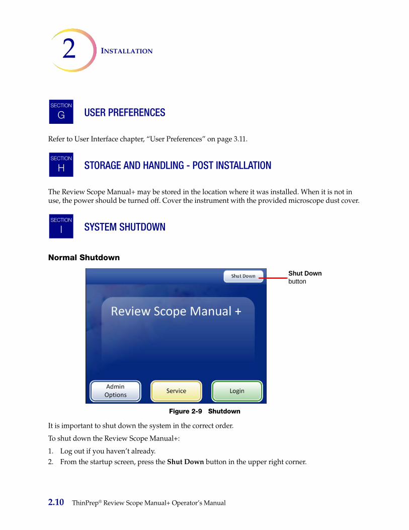
INSTALLATION2
USER PREFERENCES
Refer to User Interface chapter, “User Preferences” on page 3.11.
STORAGE AND HANDLING - POST INSTALLATION
The Review Scope Manual+ may be stored in the location where it was installed. When it is not in use, the power should be turned off. Cover the instrument with the provided microscope dust cover.
SYSTEM SHUTDOWN
Normal Shutdown
Figure 2-9 Shutdown
It is important to shut down the system in the correct order.
To shut down the Review Scope Manual+:
1. Log out if you haven’t already.2. From the startup screen, press the Shut Down button in the upper right corner.
SECTION
G
SECTION
H
SECTION
I
Shut Down button
2.10 ThinPrep® Review Scope Manual+ Operator’s Manual
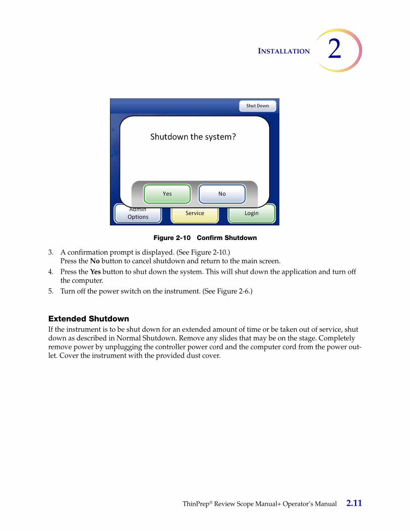
2INSTALLATION
Figure 2-10 Confirm Shutdown
3. A confirmation prompt is displayed. (See Figure 2-10.) Press the No button to cancel shutdown and return to the main screen.
4. Press the Yes button to shut down the system. This will shut down the application and turn off the computer.
5. Turn off the power switch on the instrument. (See Figure 2-6.)
Extended ShutdownIf the instrument is to be shut down for an extended amount of time or be taken out of service, shut down as described in Normal Shutdown. Remove any slides that may be on the stage. Completely remove power by unplugging the controller power cord and the computer cord from the power out-let. Cover the instrument with the provided dust cover.
ThinPrep® Review Scope Manual+ Operator’s Manual 2.11

INSTALLATION2
This page intentionally left blank.
2.12 ThinPrep® Review Scope Manual+ Operator’s Manual

3. User In
terface 3. U
ser
Inte
rfac
e
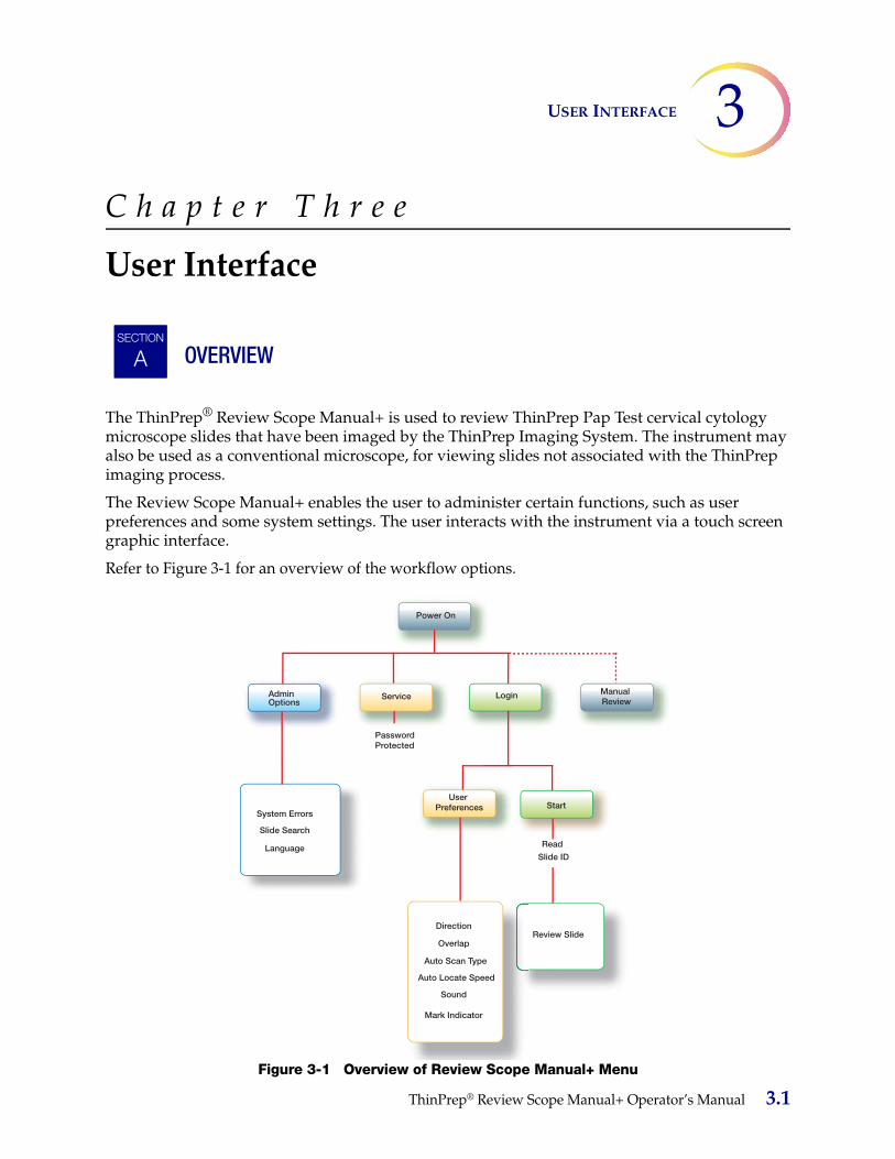
3USER INTERFACE
C h a p t e r T h r e e
User Interface
OVERVIEW
The ThinPrep® Review Scope Manual+ is used to review ThinPrep Pap Test cervical cytology microscope slides that have been imaged by the ThinPrep Imaging System. The instrument may also be used as a conventional microscope, for viewing slides not associated with the ThinPrep imaging process.
The Review Scope Manual+ enables the user to administer certain functions, such as user preferences and some system settings. The user interacts with the instrument via a touch screen graphic interface.
Refer to Figure 3-1 for an overview of the workflow options.
Figure 3-1 Overview of Review Scope Manual+ Menu
SECTION
ASECTION
A
Start
PasswordProtected
User Preferences
Review Slide
System Errors
Slide Search
Language
Direction
Overlap
Auto Scan Type
Auto Locate Speed
Sound
Mark Indicator
Power On
LoginAdminOptions
ServiceManual Review
Read
Slide ID
ThinPrep® Review Scope Manual+ Operator’s Manual 3.1

USER INTERFACE3
This chapter introduces the user interface modules of the Review Scope Manual+ and describes the usage of each. It is recommended that users acquaint themselves with the material in this chapter before operating the instrument.
The content found in this chapter:
STARTUP . . . . . . . . . . . . . . . . . . . . . . . . . . . . . . . . . . . . . . . . . . . . . . . . . . 3.3
ADMINISTRATIVE OPTIONS. . . . . . . . . . . . . . . . . . . . . . . . . . . . . . . . 3.4
• System Errors. . . . . . . . . . . . . . . . . . . . . . . . . . . . . . . . . . . . . . . . . . . . 3.4
• Slide Search . . . . . . . . . . . . . . . . . . . . . . . . . . . . . . . . . . . . . . . . . . . . . 3.5
• Language . . . . . . . . . . . . . . . . . . . . . . . . . . . . . . . . . . . . . . . . . . . . . . . 3.7
LOGIN . . . . . . . . . . . . . . . . . . . . . . . . . . . . . . . . . . . . . . . . . . . . . . . . . . . . 3.9
MAIN MENU . . . . . . . . . . . . . . . . . . . . . . . . . . . . . . . . . . . . . . . . . . . . . . 3.10
USER PREFERENCES . . . . . . . . . . . . . . . . . . . . . . . . . . . . . . . . . . . . . . . 3.11
• Scan Direction . . . . . . . . . . . . . . . . . . . . . . . . . . . . . . . . . . . . . . . . . . . 3.11
• Scan Overlap . . . . . . . . . . . . . . . . . . . . . . . . . . . . . . . . . . . . . . . . . . . . 3.12
• Scan Type . . . . . . . . . . . . . . . . . . . . . . . . . . . . . . . . . . . . . . . . . . . . . . . 3.12
• Speed . . . . . . . . . . . . . . . . . . . . . . . . . . . . . . . . . . . . . . . . . . . . . . . . . . 3.17
• Sound . . . . . . . . . . . . . . . . . . . . . . . . . . . . . . . . . . . . . . . . . . . . . . . . . . 3.19
• Mark Indicator . . . . . . . . . . . . . . . . . . . . . . . . . . . . . . . . . . . . . . . . . . 3.20
START. . . . . . . . . . . . . . . . . . . . . . . . . . . . . . . . . . . . . . . . . . . . . . . . . . . . . 3.21
3.2 ThinPrep® Review Scope Manual+ Operator’s Manual
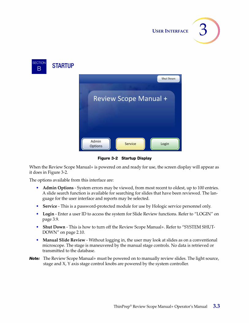
3USER INTERFACE
STARTUP
Figure 3-2 Startup Display
When the Review Scope Manual+ is powered on and ready for use, the screen display will appear as it does in Figure 3-2.
The options available from this interface are:
• Admin Options - System errors may be viewed, from most recent to oldest, up to 100 entries. A slide search function is available for searching for slides that have been reviewed. The lan-guage for the user interface and reports may be selected.
• Service - This is a password-protected module for use by Hologic service personnel only.
• Login - Enter a user ID to access the system for Slide Review functions. Refer to “LOGIN” on page 3.9.
• Shut Down - This is how to turn off the Review Scope Manual+. Refer to “SYSTEM SHUT-DOWN” on page 2.10.
• Manual Slide Review - Without logging in, the user may look at slides as on a conventional microscope. The stage is maneuvered by the manual stage controls. No data is retrieved or transmitted to the database.
Note: The Review Scope Manual+ must be powered on to manually review slides. The light source, stage and X, Y axis stage control knobs are powered by the system controller.
SECTION
B
ThinPrep® Review Scope Manual+ Operator’s Manual 3.3

USER INTERFACE3
ADMINISTRATIVE OPTIONS
Figure 3-3 Administrative Options Screen
The Administrative Options screen displays
• Instrument serial number
• Usage summary
• System errors
• Slide Search
• Language
Instrument Serial NumberThe instrument is given a unique serial number at the factory. This is not user -changeable.
Usage SummaryThe Usage Summary displays the number of slide reviews that have been performed on the instrument. It does not include manual slide reviews that were performed off-line.
System Errors
Figure 3-4 System Errors Button
SECTION
C
3.4 ThinPrep® Review Scope Manual+ Operator’s Manual

3USER INTERFACE
The System Errors screen displays all of the error conditions encountered during slide review (100 are stored at one time). See Figure 3-5. The events are listed from most recent to oldest. Use the up/down arrows to scroll through the list using the touch screen.
Figure 3-5 System Events Screen
Slide Search
Figure 3-6 Slide Search Button
To search for a specific slide, enter the slide ID using the keypad buttons. See Figure 3-7. Press the Continue button when ready to perform the search.
Note: Only enter the first 11 digits of the number. Do not type in the last three CRC digits.
Entering slide IDsDepending on which configuration of the Imaging System server the Review Scope Manual+ is con-nected to, the keypad will be numeric or will have a Switch Keys button, which allows the user access to alternate keypads. Use these alternate keypads to enter a slide ID that contains alphanu-merics or special characters. See Figure 3-8.
Current date
Software version
Scroll button
Instrument serial number
List of system events
Press the Done button to return to the Adminis-trative Options screen.
ThinPrep® Review Scope Manual+ Operator’s Manual 3.5
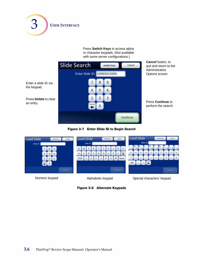
USER INTERFACE3
Figure 3-7 Enter Slide ID to Begin Search
Figure 3-8 Alternate Keypads
Enter a slide ID via the keypad.
Press Delete to clear an entry.
Cancel button, to quit and return to the Administrative Options screen
Press Continue to perform the search.
Press Switch Keys to access alpha or character keypads. (Not available with some server configurations.)
Numeric keypad Alphabetic keypad Special characters’ keypad
3.6 ThinPrep® Review Scope Manual+ Operator’s Manual
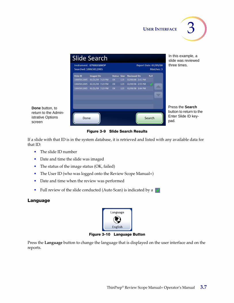
3USER INTERFACE
Figure 3-9 Slide Search Results
If a slide with that ID is in the system database, it is retrieved and listed with any available data for that ID:
• The slide ID number
• Date and time the slide was imaged
• The status of the image status (OK, failed)
• The User ID (who was logged onto the Review Scope Manual+)
• Date and time when the review was performed
• Full review of the slide conducted (Auto Scan) is indicated by a
Language
Figure 3-10 Language Button
Press the Language button to change the language that is displayed on the user interface and on the reports.
In this example, a slide was reviewed three times.
Done button, to return to the Admin-istrative Options screen
Press the Search button to return to the Enter Slide ID key-pad.
ThinPrep® Review Scope Manual+ Operator’s Manual 3.7
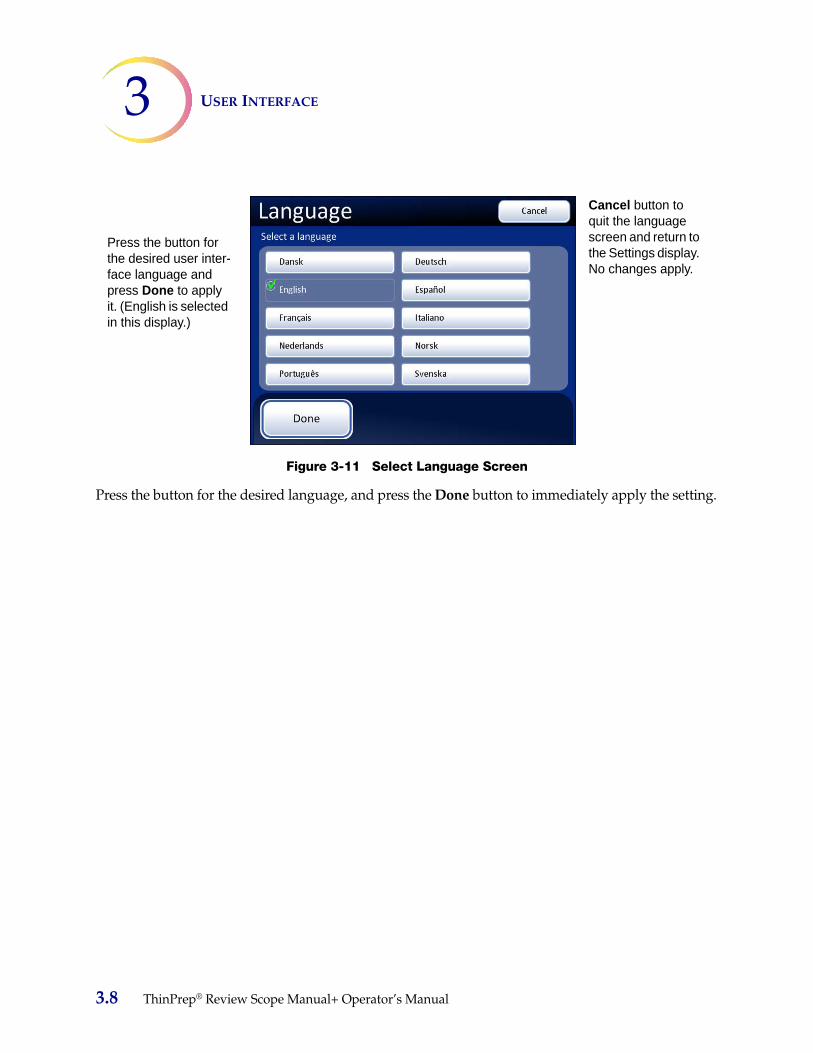
USER INTERFACE3
Figure 3-11 Select Language Screen
Press the button for the desired language, and press the Done button to immediately apply the setting.
Press the button for the desired user inter-face language and press Done to apply it. (English is selected in this display.)
Cancel button to quit the language screen and return to the Settings display. No changes apply.
3.8 ThinPrep® Review Scope Manual+ Operator’s Manual

3USER INTERFACE
LOGIN
Figure 3-12 Login Screen
To access the Slide Review functions of the Review Scope Manual+, a three-digit operator ID must be entered.
Press the digits on the display keypad and touch Continue when done.
Use the Delete key to clear mistakes. To cancel login and return to the startup screen, press the Back button.
As soon as the number is entered, the system database checks that it is a valid operator ID. Any user preferences that have been saved with that ID will be active.
The message “Invalid User ID” might occur if the three-digit number was entered incorrectly, if there is no user ID with that number, or if that number has been retired.
SECTION
D
Enter the three-digit operator ID to access the system.
Use the Delete key to clear incorrect numbers.
Back button, to cancel and return to the Startup Display
Press Continue button after entering operator ID.
ThinPrep® Review Scope Manual+ Operator’s Manual 3.9

USER INTERFACE3
MAIN MENU, (Logged In)
Figure 3-13 Main Menu Screen
Successful login will display the main screen. The name of the user who logged in is shown on the screen. Just below the name is the date and time that login started. The options available from this interface are:
• User Preferences - this module allows the cytotechnologist to adjust some of the parameters for automated slide review, such as scan direction, overlap, type, speed and sound alerts. Refer to “USER PREFERENCES” on page 3.11.
• Start - to begin using the instrument to review a slide, press the Start button. Refer to “Opera-tion” on page 4.1.
• Logout - to end the session with the Review Scope Manual+, press the Logout button. The system will return to the Startup screen. The instrument may be powered off or a user may log in to begin a new session.
SECTION
E
The name of the user
The date and time that the user logged in
User Preferences button selects settings for slide review.
Logout button, to log out and return to the Startup Display
Start button, to begin operating the Review Scope Manual+
3.10 ThinPrep® Review Scope Manual+ Operator’s Manual
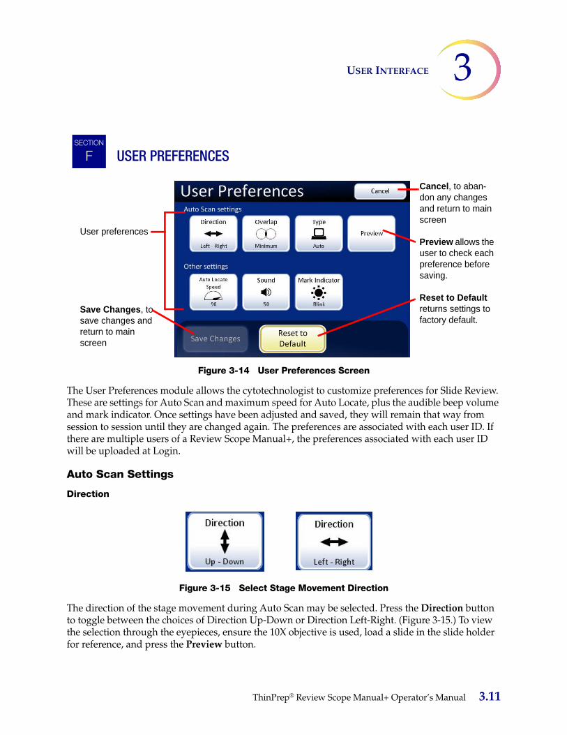
3USER INTERFACE
USER PREFERENCES
Figure 3-14 User Preferences Screen
The User Preferences module allows the cytotechnologist to customize preferences for Slide Review. These are settings for Auto Scan and maximum speed for Auto Locate, plus the audible beep volume and mark indicator. Once settings have been adjusted and saved, they will remain that way from session to session until they are changed again. The preferences are associated with each user ID. If there are multiple users of a Review Scope Manual+, the preferences associated with each user ID will be uploaded at Login.
Auto Scan Settings
Direction
Figure 3-15 Select Stage Movement Direction
The direction of the stage movement during Auto Scan may be selected. Press the Direction button to toggle between the choices of Direction Up-Down or Direction Left-Right. (Figure 3-15.) To view the selection through the eyepieces, ensure the 10X objective is used, load a slide in the slide holder for reference, and press the Preview button.
SECTION
FSECTION
F
User preferences
Save Changes, to save changes and return to main screen
Cancel, to aban-don any changes and return to main screen
Preview allows the user to check each preference before saving.
Reset to Default returns settings to factory default.
ThinPrep® Review Scope Manual+ Operator’s Manual 3.11

USER INTERFACE3
From the User Preferences screen, press Save Changes to retain your preference now, or continue to set your next preference.
Overlap
Figure 3-16 Select Auto Scan Overlap
Auto Scan overlap may be selected. This sets how much the fields of view overlap from row to row during Auto Scan of the cell spot. (Default is minimum.)
Press the Overlap button repeatedly to toggle between the choices of minimum, medium or maximum overlap. (Figure 3-16.) To view the selection through the eyepieces, ensure the 10X objective is in position, load a slide in the slide holder for reference, and press the Preview button.
From the User Preferences screen, press Save Changes to retain your preference now, or continue to set your next preference.
TypeThe Auto Scan function presents the entire cell spot in a defined path at 10X magnification. Three types of scan motion are selectable:
• Automatic Start/Stop
• Semiautomatic Start/Stop
• Manual+
3.12 ThinPrep® Review Scope Manual+ Operator’s Manual

3USER INTERFACE
Auto Scan - Automatic Start/Stop
Figure 3-17 Select Auto Start/Stop Scan
Scan motion is initiated by the Review Scope Manual+ and consists of a series of discrete, overlapping fields of view, including a pause at each view.
The movement of the stage speed from field of view (FOV) to field of view may be adjusted faster or slower by repeatedly pressing the -5 or +5 buttons to slow or increase the speed. (See Figure 3-17.)
The length of pause at the field of view may be adjusted to be shorter or longer by repeatedly pressing the -5 or +5 buttons to define the pause. (See Figure 3-17.)
To preview the setting, press the Done button, and then press the Preview button on the User Preferences screen.
To view the selection through the eyepieces, load a slide in the slide holder for reference, ensure the 10X objective is in position, and press the Preview button. Observe the stage movement.
To pause the scan, scroll the review control forward or press the Pause button on the touch screen. Also, changing the magnification will cause the scan to pause. To resume the scan, scroll the review control forward again or press the Resume button on the touch screen.
During scan pause, the X, Y axis stage controls are available to move the view about the cell spot. Upon resuming, the area of review will return to the part of the cell spot where you left off and continue to present the rest of the cell spot. The display on the touch screen is shown below.
Press the Cancel Scan button on the touch screen to stop the preview.
Stage speedSlowerFaster
Pause at field of viewLongerShorter
Done. Save setting adjustments and return to User Preferences screen.
ThinPrep® Review Scope Manual+ Operator’s Manual 3.13

USER INTERFACE3
Figure 3-18 Automatic Scan Mode Preview
Continue to adjust and preview the stage speed and length of pause for viewing until they are satisfactory. Press the Done button to save the settings and return to the User Preferences screen.
From the User Preferences screen, press Save Changes to retain your preference now, or continue to set your next preference.
Auto Scan - Semiautomatic Start/Stop
Figure 3-19 Select Semiautomatic Start/Stop Scan
Scan in motion Scan paused
Stage speedSlowerFaster
Done. Save setting adjustments and return to User Preferences screen.
3.14 ThinPrep® Review Scope Manual+ Operator’s Manual
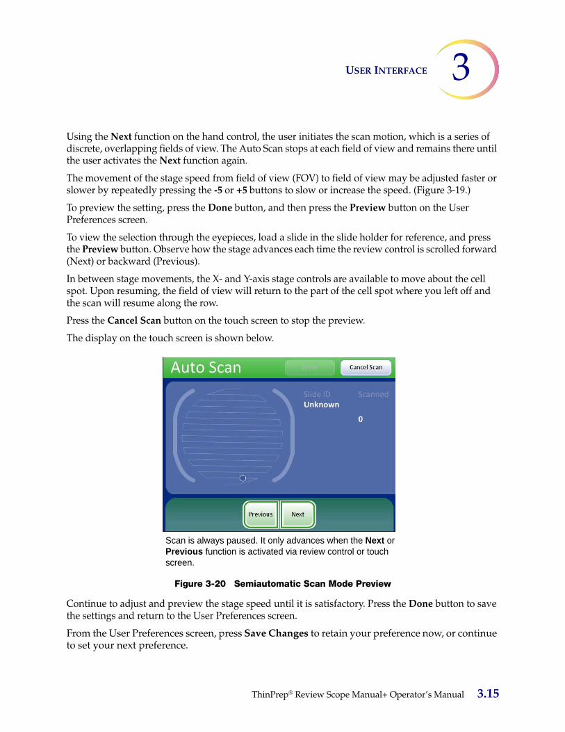
3USER INTERFACE
Using the Next function on the hand control, the user initiates the scan motion, which is a series of discrete, overlapping fields of view. The Auto Scan stops at each field of view and remains there until the user activates the Next function again.
The movement of the stage speed from field of view (FOV) to field of view may be adjusted faster or slower by repeatedly pressing the -5 or +5 buttons to slow or increase the speed. (Figure 3-19.)
To preview the setting, press the Done button, and then press the Preview button on the User Preferences screen.
To view the selection through the eyepieces, load a slide in the slide holder for reference, and press the Preview button. Observe how the stage advances each time the review control is scrolled forward (Next) or backward (Previous).
In between stage movements, the X- and Y-axis stage controls are available to move about the cell spot. Upon resuming, the field of view will return to the part of the cell spot where you left off and the scan will resume along the row.
Press the Cancel Scan button on the touch screen to stop the preview.
The display on the touch screen is shown below.
Figure 3-20 Semiautomatic Scan Mode Preview
Continue to adjust and preview the stage speed until it is satisfactory. Press the Done button to save the settings and return to the User Preferences screen.
From the User Preferences screen, press Save Changes to retain your preference now, or continue to set your next preference.
Scan is always paused. It only advances when the Next or Previous function is activated via review control or touch screen.
ThinPrep® Review Scope Manual+ Operator’s Manual 3.15
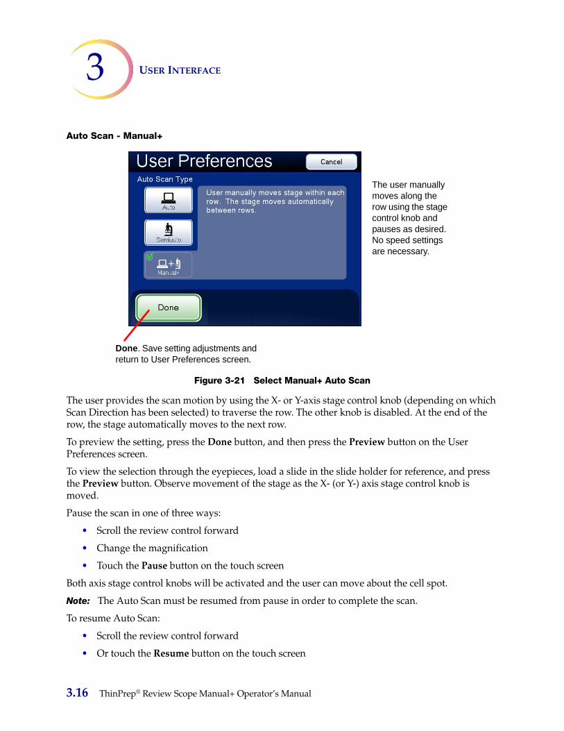
USER INTERFACE3
Auto Scan - Manual+
Figure 3-21 Select Manual+ Auto Scan
The user provides the scan motion by using the X- or Y-axis stage control knob (depending on which Scan Direction has been selected) to traverse the row. The other knob is disabled. At the end of the row, the stage automatically moves to the next row.
To preview the setting, press the Done button, and then press the Preview button on the User Preferences screen.
To view the selection through the eyepieces, load a slide in the slide holder for reference, and press the Preview button. Observe movement of the stage as the X- (or Y-) axis stage control knob is moved.
Pause the scan in one of three ways:
• Scroll the review control forward
• Change the magnification
• Touch the Pause button on the touch screen
Both axis stage control knobs will be activated and the user can move about the cell spot.
Note: The Auto Scan must be resumed from pause in order to complete the scan.
To resume Auto Scan:
• Scroll the review control forward
• Or touch the Resume button on the touch screen
The user manually moves along the row using the stage control knob and pauses as desired. No speed settings are necessary.
Done. Save setting adjustments and return to User Preferences screen.
3.16 ThinPrep® Review Scope Manual+ Operator’s Manual

3USER INTERFACE
Upon resuming, the field of view will return to the part of the cell spot where you left off and the scan will resume along the row. The display on the touch screen is shown below.
Press the Cancel Scan button on the touch screen to stop the preview.
Figure 3-22 Manual+ Scan Mode Preview
Press the Done button to save the setting and return to the User Preferences screen.
From the User Preferences screen, press Save Changes to retain your preference now, or continue to set your next preference.
Auto Locate Speed
The Auto Locate Speed setting adjusts how quickly the stage moves from field to field during presentation of the 22 fields of view. The stage moves to each field of view and stops until the user presses the Next function.
Note: Arrow icon indicates the forward direction of each row that is being scanned.
Scan in motion Scan paused
ThinPrep® Review Scope Manual+ Operator’s Manual 3.17
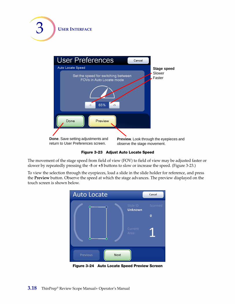
USER INTERFACE3
Figure 3-23 Adjust Auto Locate Speed
The movement of the stage speed from field of view (FOV) to field of view may be adjusted faster or slower by repeatedly pressing the -5 or +5 buttons to slow or increase the speed. (Figure 3-23.)
To view the selection through the eyepieces, load a slide in the slide holder for reference, and press the Preview button. Observe the speed at which the stage advances. The preview displayed on the touch screen is shown below.
Figure 3-24 Auto Locate Speed Preview Screen
Stage speedSlowerFaster
Done. Save setting adjustments and return to User Preferences screen.
Preview. Look through the eyepieces and observe the stage movement.
3.18 ThinPrep® Review Scope Manual+ Operator’s Manual
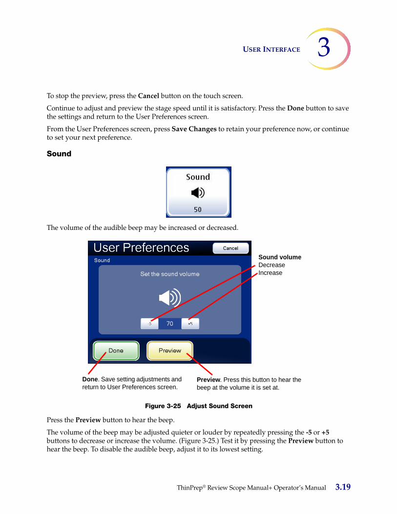
3USER INTERFACE
To stop the preview, press the Cancel button on the touch screen.
Continue to adjust and preview the stage speed until it is satisfactory. Press the Done button to save the settings and return to the User Preferences screen.
From the User Preferences screen, press Save Changes to retain your preference now, or continue to set your next preference.
Sound
The volume of the audible beep may be increased or decreased.
Figure 3-25 Adjust Sound Screen
Press the Preview button to hear the beep.
The volume of the beep may be adjusted quieter or louder by repeatedly pressing the -5 or +5 buttons to decrease or increase the volume. (Figure 3-25.) Test it by pressing the Preview button to hear the beep. To disable the audible beep, adjust it to its lowest setting.
Sound volumeDecreaseIncrease
Done. Save setting adjustments and return to User Preferences screen.
Preview. Press this button to hear the beep at the volume it is set at.
ThinPrep® Review Scope Manual+ Operator’s Manual 3.19

USER INTERFACE3
Continue to adjust and preview the beep volume until it is satisfactory. Press the Done button to save the setting and return to the User Preferences screen.
From the User Preferences screen, press Save Changes to retain your preference now, or continue to set your next preference.
Mark Indicator
Figure 3-26 Mark Indicator Button
When an electronic mark is made via the review control or the touch screen, it is indicated by the instrument either as a blink (seen through the binoculars as the light source turning off then on) or as a beep (heard as an audible alert). Use this setting to select which indicator is enabled.
Figure 3-27 Select Blink or Beep Mark Indicator
When the review control or touch screen is pressed to make a mark, the indicator will blink or beep once. If it is pressed again to unmark the area, the indicator blinks or beeps twice, to differentiate.
Note: The volume of the beep is the same as the sound volume setting in the user preferences.
Therefore, if an audible beep is desired to indicate end of Auto Locate and end of Auto Scan, it will also be heard for mark/unmark.
If the audible beep is turned too low to hear, then it will not be heard for Auto Locate, Auto Scan and mark/unmark.
Mark Indicator - blink selected Mark Indicator - beep selected
3.20 ThinPrep® Review Scope Manual+ Operator’s Manual

3USER INTERFACE
Reset to Default
Figure 3-28 Reset to Default Button
User preferences may be reset to the factory defaults by pressing the Reset to Default button. System defaults are:
• Direction - left/right
• Overlap - minimum
• Auto Scan type - Auto Start/Stop
• Auto Locate speed - 90% (of stage movement capability)
• Stage speed between fields of view - 50%
• Time spent at each field of view - 50%
• Sound - 50% of beep volume
• Mark Indicator - blink
START (Begin using the Review Scope Manual+)
Press the Start button to begin review of a slide.
Refer to Chapter 4, Operation for instructions on operating the Review Scope Manual+.
SECTION
G
ThinPrep® Review Scope Manual+ Operator’s Manual 3.21

USER INTERFACE3
This page intentionally left blank.
3.22 ThinPrep® Review Scope Manual+ Operator’s Manual

4. Op
eration
4. O
per
atio
n

4OPERATION
C h a p t e r F o u r
Operation
OVERVIEW
The ThinPrep® Review Scope Manual+ is used to review ThinPrep Pap Test cervical cytology microscope slides that have been imaged by the ThinPrep Imaging System. The slides are reviewed by a cytotechnologist (CT). The instrument may also be used as a conventional microscope, for viewing slides not associated with the ThinPrep imaging process.
Slide Review
Auto ReviewIn this manual, Auto Review refers to a slide review in which the Review Scope Manual+:
• scans the slide ID number from the slide
• communicates with the database for appropriate slide data record
• makes use of the Auto Locate function (where the 22 fields of view identified by the imaging process are presented to the cytotechnologist)
• makes use of the Auto Scan function, as required or desired
• writes slide data record to the database at conclusion of slide review
(Refer to Figure 4-1 for a graphical representation of the typical slide review process.)
Subsequent ReviewA slide that has undergone Auto Review may be reviewed again, making use of the Auto Locate, review and Auto Scan functions. Further electronic marks may be added (to a maximum of 30 marks on a slide), but no previous marks may be removed. The slide data record will be revised in the database at the conclusion of the review.
Note: Slides previously screened either via Auto Review or manually may always be examined again manually.
Manual ReviewManual Review refers to a slide review in which:
• patient slide data is not retrieved from or communicated to the database
SECTION
ASECTION
A
ThinPrep® Review Scope Manual+ Operator’s Manual 4.1

OPERATION4
• a review of the entire cell spot is conducted by the CT, manually operating the illumination, focus, magnification and stage movement
• there is no update of the slide data record in the database
Slide Data RecordThe slide data record is the accumulation of all imaging and review events the slide encounters. The Usage Summary and Slide Search reports are generated from data that is in the slide data record. A slide data record is generated when a valid slide ID is accepted into the Imaging System’s database. Items that are associated with the slide data record include:
• Date/time stamp when Imaging began and ended (even if imaging was unsuccessful)
• Serial number of the Image Processor that imaged the slide
• Fiducial mark coordinates
• Field of view coordinates
• Date/time stamp when slide review began and ended (including subsequent reviews)
• Serial number of the Review Scope Manual+ that reviewed the slide
• Operator ID for each review of the slide (including subsequent reviews)
• Status whether Auto Scan was completed for each review
• Electronic mark coordinates
4.2 ThinPrep® Review Scope Manual+ Operator’s Manual

4OPERATION
Figure 4-1 Typical Slide Review Process
Electronic MarksMade
No Electronic MarksMade
(Full Review)
Power On
User Login
Load Slide
Scan Slide ID
Locate Fiducial Marks
Auto Locate(22 fields of view)
Review Electronic Marks(optional)
Auto Scan(optional)
Auto Scan
Review Electronic Marks(optional)
Mark Slide Manually
Scan Slide ID
Locate Fiducial Marks
Update Slide Data Record
Unload Slide
ThinPrep® Review Scope Manual+ Operator’s Manual 4.3

OPERATION4
MATERIALS REQUIRED PRIOR TO OPERATION
• Prepared ThinPrep Pap Test microscope slides
• ThinPrep Review Scope Manual+
• Marking pen for slide marking
Important Operational Notes:• During Auto Locate, always examine the entire Field of View.
• Marking the slide - the slides are manually marked by the CT. Follow your laboratory’s guide-lines for marking slides. It is recommended that at least Auto Locate is completed prior to making any physical marks.
USING THE TOUCH SCREEN AND REVIEW CONTROLS
Touch ScreenThe touch screen can be adjusted higher or lower from the desktop by sliding it up or down along its mounting rail. The screen will stay at the height it is left at. The range is between 12.7 to 30.4 cm (5 to 12 inches) above the desktop.
The touch screen horizontal or vertical tilt may be adjusted to fit user preferences. See Figure 4-2. Turn the adjustment knob to loosen and adjust the tilt, then tighten the knob when the screen is in the desired position.
SECTION
B
SECTION
C
4.4 ThinPrep® Review Scope Manual+ Operator’s Manual

4OPERATION
Figure 4-2 Touch Screen Horizontal and Vertical Axes Adjustment (two microscope configurations shown)
Review ControlThe review control has a scroll wheel that acts like the scroll wheel found on a computer mouse. It enables the operator to execute the main review functions (Next, Previous, Mark) without having to take their eyes away from the binoculars.
Adjust vertical axis tilt using the adjustment knob at the top of the rail.
Adjust horizontal axis tilt using the adjustment knob on the rear of the screen.
Adjustment knob
Adjustment knob
ThinPrep® Review Scope Manual+ Operator’s Manual 4.5

OPERATION4
Figure 4-3 The Review Control
The review functions are:
Next used to advance through functions used to pause/resume stage motion during Auto Scan used to adjust user preference settings
Previous used to return to fields of view during review used to adjust user preference settings
Mark used to electronically mark or unmark areas for dotting
Previous(Clockwise) Next
(Counterclock-wise)
Mark/unmark(Push)
4.6 ThinPrep® Review Scope Manual+ Operator’s Manual

4OPERATION
SLIDE REVIEW
To begin slide review, log in to the system with a valid user ID. Press the Start button.
Figure 4-4 Log In and Start
A message on the screen prompts for a slide to be loaded onto the stage.
Figure 4-5 Load Slide Screen
SECTION
D
Press the Start button.
ThinPrep® Review Scope Manual+ Operator’s Manual 4.7
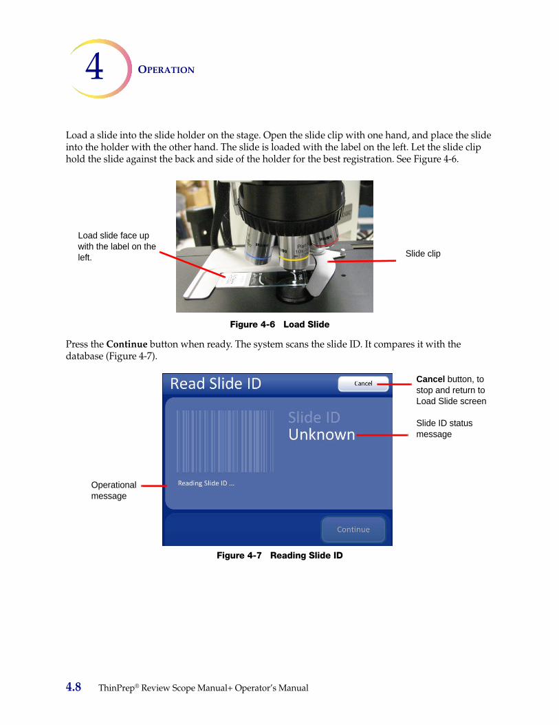
OPERATION4
Load a slide into the slide holder on the stage. Open the slide clip with one hand, and place the slide into the holder with the other hand. The slide is loaded with the label on the left. Let the slide clip hold the slide against the back and side of the holder for the best registration. See Figure 4-6.
Figure 4-6 Load Slide
Press the Continue button when ready. The system scans the slide ID. It compares it with the database (Figure 4-7).
Figure 4-7 Reading Slide ID
Slide clip
Load slide face up with the label on the left.
Operational message
Cancel button, to stop and return to Load Slide screen
Slide ID status message
4.8 ThinPrep® Review Scope Manual+ Operator’s Manual
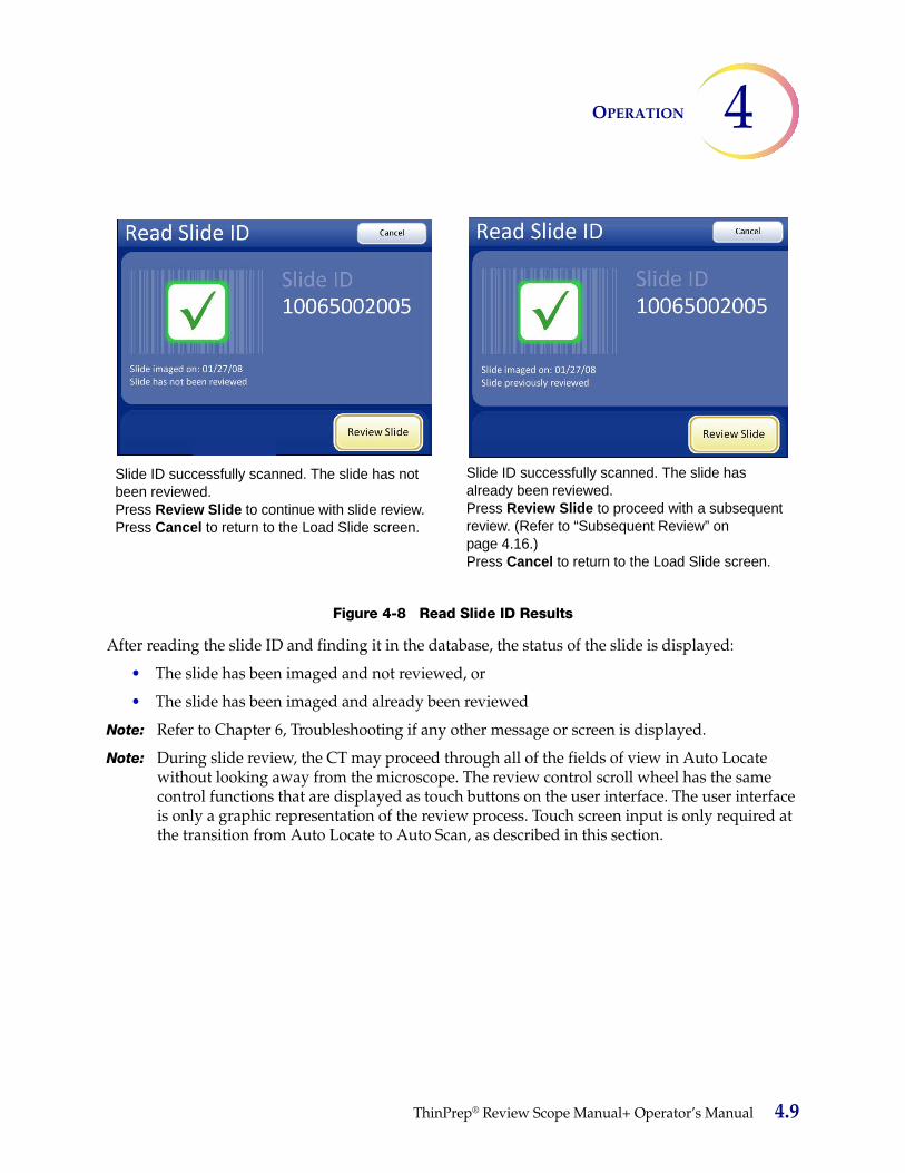
4OPERATION
Figure 4-8 Read Slide ID Results
After reading the slide ID and finding it in the database, the status of the slide is displayed:
• The slide has been imaged and not reviewed, or
• The slide has been imaged and already been reviewed
Note: Refer to Chapter 6, Troubleshooting if any other message or screen is displayed.
Note: During slide review, the CT may proceed through all of the fields of view in Auto Locate without looking away from the microscope. The review control scroll wheel has the same control functions that are displayed as touch buttons on the user interface. The user interface is only a graphic representation of the review process. Touch screen input is only required at the transition from Auto Locate to Auto Scan, as described in this section.
Slide ID successfully scanned. The slide has not been reviewed. Press Review Slide to continue with slide review.Press Cancel to return to the Load Slide screen.
Slide ID successfully scanned. The slide has already been reviewed.Press Review Slide to proceed with a subsequent review. (Refer to “Subsequent Review” on page 4.16.)Press Cancel to return to the Load Slide screen.
ThinPrep® Review Scope Manual+ Operator’s Manual 4.9
OPERATION4
Auto LocateThe Auto Locate feature presents the 22 fields of interest that have been identified by the Imaging system. The fields are presented in geographic order as they are located on the slide, not by any significance in ranking. The CT must scan the entire field of view for each of the 22 fields that are presented.
CAUTION: Scan the entire field of view
Every field is presented at 10X magnification. At each location the operator may:
• focus as necessary
• manually switch to a different objective
• move about the cell spot using the stage control knobs
• return to the previous location by activating Previous using the review control or the touch screen
• add and remove electronic marks by pressing Mark using the review control or the touch screen
To advance to the next location, the 10X objective must be in the engaged position. Activate Next using the review control or the touch screen.
Note: The speed that the stage moves from location to location when Next or Previous is used is a user-adjustable preference. Refer to “Auto Locate Speed” on page 3.17.
4.10 ThinPrep® Review Scope Manual+ Operator’s Manual

4OPERATION
Figure 4-9 Auto Locate Screen
Mark IndicatorThe mark indicator is set up in User Preferences as either a blink in the field of view or an audible beep (page 3.20).
When the review control or touch screen is pressed to make a mark, the indicator will blink or beep once. If it is pressed again to unmark the area, the indicator blinks or beeps twice, to differentiate.
Note: The audible beep that indicates mark/unmark is the same beep for the audible alarm. The beep volume is adjusted via user preference (page 3.19).
22 fields of interest are graphically repre-sented.
As each location is vis-ited, the dot changes.
Previous button, to go back one field of view
Next button, to pro-ceed to next field of view
Mark button, to elec-tronically mark an area of interest.
Cancel button, to end slide review and return to the Load Slide screen
The slide ID and the date of imaging.
Number of electronic marks made.
Current area - which field of view is pre-sented
Auto Locate in prog-ress; electronic marks display as yellow dot with an x.
Number of elec-tronic marks made
Current area - which field of view is pre-sented
Do not remove the slide from the stage during Auto Locate. To end slide review before finishing, press the Cancel button.
ThinPrep® Review Scope Manual+ Operator’s Manual 4.11

OPERATION4
Figure 4-10 Auto Locate Complete
When all 22 fields have been viewed, an audible beep will sound. The display indicates the Auto Locate function is complete. The system is in a paused state. You may go to previous locations and continue to mark and unmark. See Figure 4-10.
Note: If a check for specimen adequacy or endocervical component is indicated, do it now before leaving Auto Locate. See the next section.
Specimen AdequacyAfter presenting the 22 fields of interest in the Auto Locate mode, the stage positions the field of view at the topmost edge of the cell spot and stops. On the user interface, the path through the fields of view is removed. See Figure 4-11.
Figure 4-11 Stage in Position for Specimen Adequacy Check
Auto Locate complete with marks made Auto Locate complete with no marks made
4.12 ThinPrep® Review Scope Manual+ Operator’s Manual

4OPERATION
The system does not determine specimen adequacy; use your standard lab protocol. To estimate the cellularity of the preparation in scantly cellular specimens, a specimen adequacy check can be performed. In accordance with Bethesda 2001 criteria1, a minimum of 10 fields should be counted along a diameter of the cell spot that includes the center. Dependent upon the microscope objective used, use the chart below and count the average number of cells in each field.
Use the stage control knobs to traverse the cell spot.
Press the Continue button to proceed:
• Auto Scan if any marks were made or further review is desired
• complete the review if no marks were made and no further review is desired
• press the Cancel button to cancel the review (No slide data will be written to the database.)
Review MarksIf electronic marks were made during review of the 22 fields of interest, they can be reviewed prior to proceeding with Auto Scan. This is an optional step. Press the Review Marks button on the touch screen. The stage will present the marks in the order they were made. Use Next and Previous to move among the locations. Marks may be added or deleted at this time.
1. Bethesda 2001 Workshop Recommendations. The Bethesda System for Reporting Cervical Cytology, Second edition, 2004, Spring Science and Business Media, LLC.
FN 22 Eyepiece/10X Objective
FN 22 Eyepiece/40X Objective
PREP DIAMmm
AREATotal
Number of Fields
Number of Cells per Field for 5,000 Total
Total Number of Fields
Number of Cells per Field for 5,000 Total
20 314.2 82.6 60.5 1322 3.8
ThinPrep® Review Scope Manual+ Operator’s Manual 4.13

OPERATION4
Figure 4-12 Review Marks Screen
Auto ScanCAUTION: Auto Scan must be done if any electronic marks have been made.
If electronic marks were made during review of the 22 fields of interest, a review of the entire cell spot is required. If no marks were made, a scan of the entire cell spot is available but not required.
The Auto Scan feature presents the entire cell spot in a defined path at 10X objective. During Auto Scan the operator may:
• focus as necessary
• pause and resume stage motion
• manually switch to a different objective
• move about the cell spot using the stage control knobs
• advance to the next location by pressing the Next button using the review control or the touch screen (in Semiautomatic mode)
• return to the previous location by pressing the Previous button using the review control or the touch screen (in Semiautomatic mode)
• add and remove electronic marks by pressing the Mark button using the review control or the touch screen
Note: Preferences for scan mode must be set up ahead of time, in the user preference menu (i.e., scan type, speed, overlap, etc.). Refer to “User Preferences” on page 3.11.
At the Auto Locate Complete screen, press the Continue button.
Areas marked elec-tronically are dis-played as yellow dots with an x. The large dot indicates the cur-rent field of view loca-tion.
Previous button, to go back one field of view
Next button, to advance to next field of view
Return button, to return to Auto Locate screen
Slide data
Number of elec-tronic marks made
Current mark being viewed
Mark button, to make additional marks or unmark existing marks
4.14 ThinPrep® Review Scope Manual+ Operator’s Manual

4OPERATION
Figure 4-13 Auto Scan Screen (Automatic scan type shown)
Depending on the type of scan mode that is chosen, the stage motion is user-initiated or self-driven. Use the scroll wheel on the review control or buttons on the touch screen to pause and resume stage motion as desired. Electronic marks may be added, removed or left as is.
• Automatic Start/Stop: the stage moves and pauses automatically. To enforce a pause to view an object longer or to manually maneuver about the cell spot, move the scroll wheel forward to pause, and forward again to resume. To make an electronic mark, pause the scan and press the scroll wheel.
• Semiautomatic Start/Stop: the stage only moves to the next view by operator prompt. Move the scroll wheel forward for each movement of the stage. Move the scroll wheel back to move to a previous view. Press the scroll wheel to make an electronic mark.
• Manual+ : The operator moves along the length of each row by using the stage control knob. You are constrained to that row until the end has been reached, and then the instrument auto-matically moves over to the next row. To manually maneuver to an object during Auto Scan, move the scroll wheel forward to pause Auto Scan. Move the scroll wheel forward again, to resume Auto Scan. To make an electronic mark, pause the scan and press the scroll wheel.
When the entire cell spot has been scanned, an audible beep will sound. To finish the review, touch the Complete Review button on the touch screen. See Figure 4-14.
Note: Do not remove the slide from the stage during Auto Scan. To end Auto Scan before finishing, press the Cancel Scan button.
The user interface returns to the Auto Locate Complete screen.
During scanning During scan pause
ThinPrep® Review Scope Manual+ Operator’s Manual 4.15

OPERATION4
Figure 4-14 Auto Scan Complete
The operator may:
• press Review Marks to see the electronically marked locations again
• manually mark the slide
Note: To facilitate marking the slide with the marking pen, press the Review Marks button and mark as each location is presented to you.
• press Complete Review to save the slide review data to the database and return to the main screen
• press Cancel Scan to end slide review and return to the Auto Locate Complete screen.
Subsequent ReviewA slide that has already been reviewed may be reviewed again. When the slide ID is scanned, the slide data record is retrieved from the database. See Figure 4-15.
Cancel Scan button, to quit Auto Scan and return to Auto Locate screen.
Review electronic marks that have been made.
Complete Review - the system does functional checks, verifies the slide ID and writes slide data to the database.
4.16 ThinPrep® Review Scope Manual+ Operator’s Manual

4OPERATION
Figure 4-15 Slide Previously Reviewed
Press the Review Slide button to continue with review of the slide. The review goes in the same order as an initial review: Auto Locate and then Auto Scan with a chance to review marks. Auto Scan and Auto Locate are optional during a subsequent review.
Figure 4-16 Auto Locate During Subsequent Review
Auto Locate presents the same 22 fields of interest that have been identified by the Imaging System. (The coordinates are stored as part of the slide data record.) If electronic marks have been made during previous review(s), they are indicated as highlighted areas on the graphic interface.
More electronic marks may be added, up to a total of 30 on a slide. No previous mark can be eliminated.
Slide status message:
Already imaged
Previously reviewed
Cancel button, to return to Load Slide screen
Review Slide but-ton, to proceed with slide review
Auto Locate pres-ents the 22 fields of view including any electronic marks that were made previously.
Skip button to bypass Auto Locate and proceed to the Auto Locate Com-plete screen
ThinPrep® Review Scope Manual+ Operator’s Manual 4.17
OPERATION4
The operator may review marks, perform an Auto Scan, complete review or skip to the Auto Locate Complete screen.
The slide data record will be updated to reflect:
• The time/date stamp that is written to the database at the time the slide is reviewed
• The user ID of the operator who conducted the review
• Coordinates of any electronic marks that were are added during the review
To leave Auto Locate before all 22 fields have been viewed, press the Skip button. This will transition to the Auto Locate complete screen. Then press the Cancel button. No data is saved to the server.
REVIEW OF SLIDES NOT FOR USE WITH THINPREP IMAGING
If the Review Scope Manual+ is used to look at slides not used with the ThinPrep® Imaging system, the power must be on in order for the controller to power the illumination, stage and X,Y axis stage controls.
The stage motion, focus, magnification and illumination are all manually adjusted by the user. Follow your lab protocols for handling and screening of slides not for use with the ThinPrep Imaging System.
SECTION
E
4.18 ThinPrep® Review Scope Manual+ Operator’s Manual

5. Main
tenan
ce 5. M
ain
ten
ance
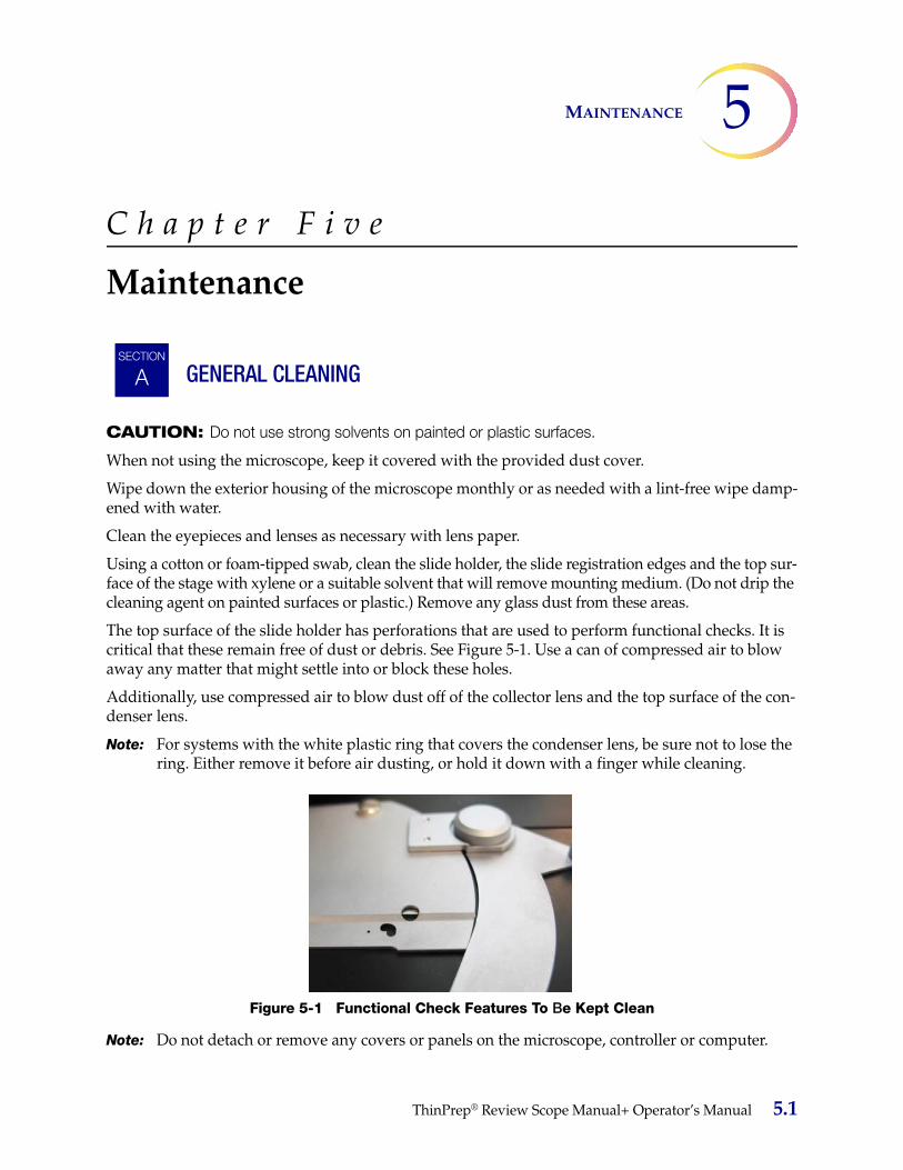
5MAINTENANCE
C h a p t e r F i v e
Maintenance
GENERAL CLEANING
CAUTION: Do not use strong solvents on painted or plastic surfaces.
When not using the microscope, keep it covered with the provided dust cover.
Wipe down the exterior housing of the microscope monthly or as needed with a lint-free wipe damp-ened with water.
Clean the eyepieces and lenses as necessary with lens paper.
Using a cotton or foam-tipped swab, clean the slide holder, the slide registration edges and the top sur-face of the stage with xylene or a suitable solvent that will remove mounting medium. (Do not drip the cleaning agent on painted surfaces or plastic.) Remove any glass dust from these areas.
The top surface of the slide holder has perforations that are used to perform functional checks. It is critical that these remain free of dust or debris. See Figure 5-1. Use a can of compressed air to blow away any matter that might settle into or block these holes.
Additionally, use compressed air to blow dust off of the collector lens and the top surface of the con-denser lens.
Note: For systems with the white plastic ring that covers the condenser lens, be sure not to lose the ring. Either remove it before air dusting, or hold it down with a finger while cleaning.
Figure 5-1 Functional Check Features To Be Kept Clean
Note: Do not detach or remove any covers or panels on the microscope, controller or computer.
SECTION
ASECTION
A
ThinPrep® Review Scope Manual+ Operator’s Manual 5.1

MAINTENANCE5
KOEHLER ALIGNMENT
Keeping the Review Scope Manual+ in good Koehler alignment will help optimize the proper illumi-nation and contrast. It aids CT slide review by reducing extraneous light.
Figure 5-2 Koehler Alignment
1. Lower the condenser down one inch below the stage by adjusting the condenser height knob.2. Load a slide with stained cells into the slide holder (with the slide label on the left).3. Focus on the cells using the 10X objective and observing through the fixed focus ocular on the
right.4. Reduce the collector (field iris) to its smallest aperture diameter by rotating the diaphragm collar
counterclockwise. 5. Focus (sharpen the contrast of the edges of the aperture) by adjusting the condenser height up or
down.6. Open the collector (field iris) aperture until it is slightly smaller than the field of view. 7. Rotate the two condenser centering thumbscrews to center the aperture.8. Adjust the condenser height until sharp, crisp edges are observed.9. Open the collector aperture until it just disappears from view.
SECTION
B
Condenser height adjustment knob
Collector (field iris)diaphragm
Condenser centering screws
Condenser diaphragm adjustment lever
5.2 ThinPrep® Review Scope Manual+ Operator’s Manual

6. Trou
blesh
oo
ting
6. T
rou
ble
sho
oti
ng
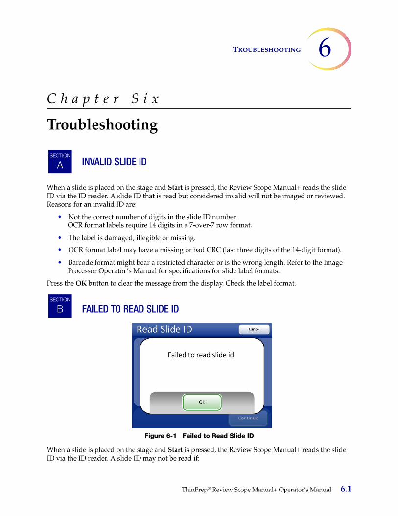
6TROUBLESHOOTING
C h a p t e r S i x
Troubleshooting
INVALID SLIDE ID
When a slide is placed on the stage and Start is pressed, the Review Scope Manual+ reads the slide ID via the ID reader. A slide ID that is read but considered invalid will not be imaged or reviewed. Reasons for an invalid ID are:
• Not the correct number of digits in the slide ID number OCR format labels require 14 digits in a 7-over-7 row format.
• The label is damaged, illegible or missing.
• OCR format label may have a missing or bad CRC (last three digits of the 14-digit format).
• Barcode format might bear a restricted character or is the wrong length. Refer to the Image Processor Operator’s Manual for specifications for slide label formats.
Press the OK button to clear the message from the display. Check the label format.
FAILED TO READ SLIDE ID
Figure 6-1 Failed to Read Slide ID
When a slide is placed on the stage and Start is pressed, the Review Scope Manual+ reads the slide ID via the ID reader. A slide ID may not be read if:
SECTION
A
SECTION
B
ThinPrep® Review Scope Manual+ Operator’s Manual 6.1
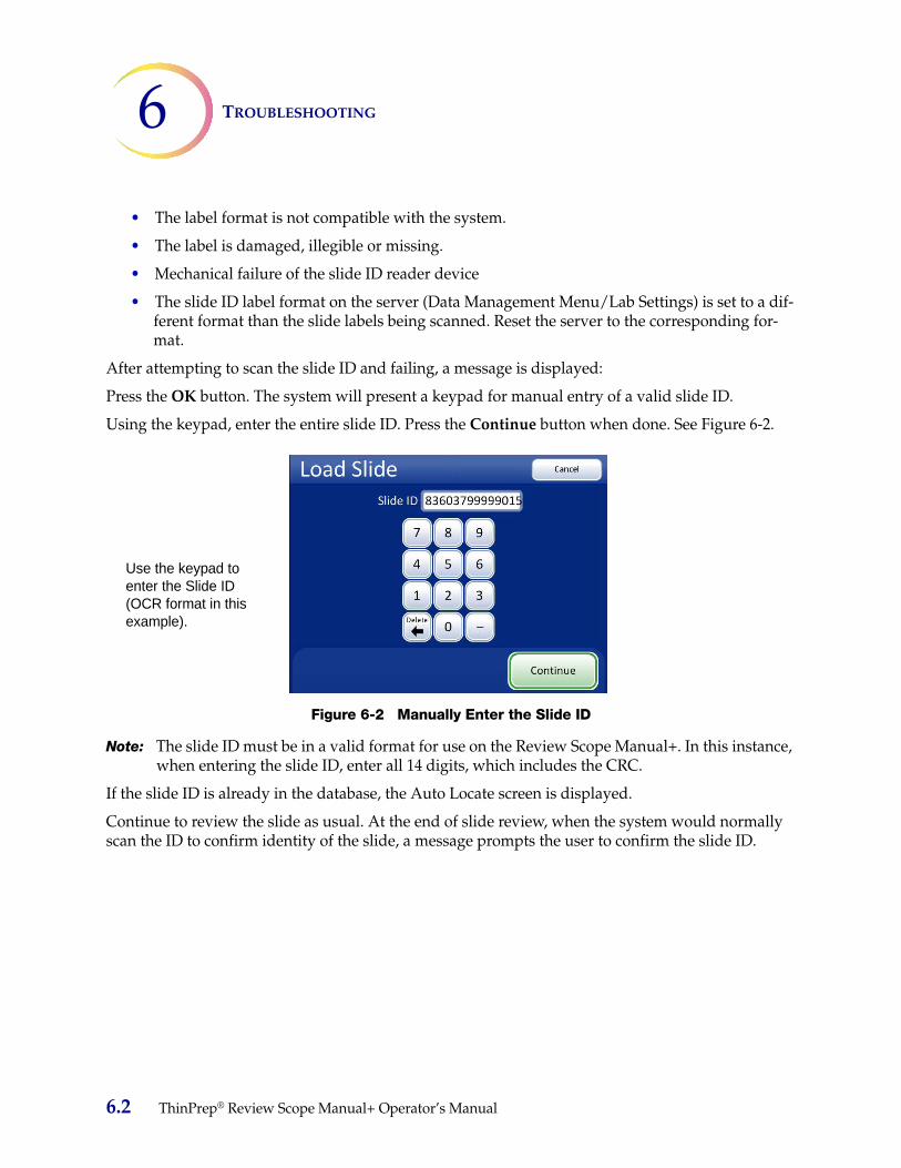
TROUBLESHOOTING6
• The label format is not compatible with the system.
• The label is damaged, illegible or missing.
• Mechanical failure of the slide ID reader device
• The slide ID label format on the server (Data Management Menu/Lab Settings) is set to a dif-ferent format than the slide labels being scanned. Reset the server to the corresponding for-mat.
After attempting to scan the slide ID and failing, a message is displayed:
Press the OK button. The system will present a keypad for manual entry of a valid slide ID.
Using the keypad, enter the entire slide ID. Press the Continue button when done. See Figure 6-2.
Figure 6-2 Manually Enter the Slide ID
Note: The slide ID must be in a valid format for use on the Review Scope Manual+. In this instance, when entering the slide ID, enter all 14 digits, which includes the CRC.
If the slide ID is already in the database, the Auto Locate screen is displayed.
Continue to review the slide as usual. At the end of slide review, when the system would normally scan the ID to confirm identity of the slide, a message prompts the user to confirm the slide ID.
Use the keypad to enter the Slide ID (OCR format in this example).
6.2 ThinPrep® Review Scope Manual+ Operator’s Manual

6TROUBLESHOOTING
Figure 6-3 Confirm Slide ID
Press Yes if the slide ID is correct. The slide review completes, and the Load Next Slide screen appears.
Press No if the ID is not correct. The slide review data will not be written to the database. The slide ID must be reconciled with your records.
Contact Technical Support if this error persists.
SLIDE ID MISMATCH WHILE COMPLETING THE REVIEW
Figure 6-4 Slide ID Mismatch
At the end of a slide review, the system scans the slide ID and compares it with the ID that it read at the beginning of the review. If the slide ID does not match, or it cannot read the slide ID, the review data is not saved to the database, and this error message is displayed. This may be caused by:
• Removal of the slide from the stage during review
• Malfunction of the slide ID reader
SECTION
C
ThinPrep® Review Scope Manual+ Operator’s Manual 6.3

TROUBLESHOOTING6
ERROR HANDLING
Note: Proper slide preparation is critical to the success of imaging by the Imaging System. If your laboratory does any of the ThinPrep® slide preparation processes, please consult the appro-priate user documentation that came with the equipment.
Recoverable ErrorsRecoverable errors are system errors that the Review Scope Manual+ can recover from with user intervention. The instrument will halt operation and present a message on the user interface. The user acknowledges the message and continues operation of the scope. The error is logged to the sys-tem error log.
Non-recoverable ErrorsNon-recoverable errors are system errors that prevent the Review Scope Manual+ from operating properly. The system will stop operation and log the error to the database. The system will need to be restarted to recover. Some of these errors or repeated errors will require field service assistance. Fig-ure 6-5 is an example of a non-recoverable error message.
Figure 6-5 Non-recoverable Error Example
If the system must be restarted to recover from an error condition, acknowledge the error message by pressing the OK button. The user interface transitions to a restricted version of the main screen, with only the Restart, Shut Down and Service buttons enabled. See Figure 6-6.
SECTION
D
6.4 ThinPrep® Review Scope Manual+ Operator’s Manual

6TROUBLESHOOTING
Figure 6-6 System Disabled Screen
To restart the Review Scope Manual+, press the Restart button. The application quits and restarts. (The computer stays powered on.) The splash screen will display while the system goes through the power on self test. The system is ready for use when the main screen displays and the Admin Options and Login buttons are active again.
If an error persists, or if the instrument cannot successfully reboot, contact Technical Support.
If you wish to turn the instrument off, rather than restart, press the Shut Down button and allow the system to quit the application and shut down the computer. Do not interfere with the instrument while this happens. After the computer has shut down, turn off the power switch on the microscope. The error should be cleared when the system next boots up. If it persists or the instrument cannot successfully boot up, contact Technical Support.
The Service button is available for Hologic service personnel to access the service mode, if a field ser-vice call is necessary.
Table 6.1: Review Scope Manual+ Error Codes
Error Number Display Message Error Type Action
6907 Calibration Error Recoverable Press OK. Attempt slide review.
6910 Calibration Error Recoverable Press OK. Attempt slide review.
6911 Calibration Error Recoverable Press OK. Attempt slide review.
6913 Calibration Error Recoverable Press OK. Attempt slide review.
ThinPrep® Review Scope Manual+ Operator’s Manual 6.5
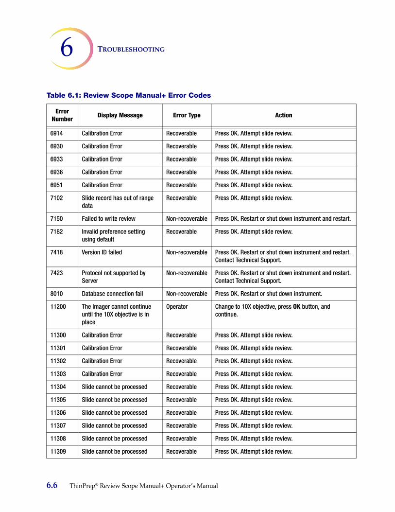
TROUBLESHOOTING6
6914 Calibration Error Recoverable Press OK. Attempt slide review.
6930 Calibration Error Recoverable Press OK. Attempt slide review.
6933 Calibration Error Recoverable Press OK. Attempt slide review.
6936 Calibration Error Recoverable Press OK. Attempt slide review.
6951 Calibration Error Recoverable Press OK. Attempt slide review.
7102 Slide record has out of range data
Recoverable Press OK. Attempt slide review.
7150 Failed to write review Non-recoverable Press OK. Restart or shut down instrument and restart.
7182 Invalid preference setting using default
Recoverable Press OK. Attempt slide review.
7418 Version ID failed Non-recoverable Press OK. Restart or shut down instrument and restart. Contact Technical Support.
7423 Protocol not supported by Server
Non-recoverable Press OK. Restart or shut down instrument and restart. Contact Technical Support.
8010 Database connection fail Non-recoverable Press OK. Restart or shut down instrument.
11200 The Imager cannot continue until the 10X objective is in place
Operator Change to 10X objective, press OK button, and continue.
11300 Calibration Error Recoverable Press OK. Attempt slide review.
11301 Calibration Error Recoverable Press OK. Attempt slide review.
11302 Calibration Error Recoverable Press OK. Attempt slide review.
11303 Calibration Error Recoverable Press OK. Attempt slide review.
11304 Slide cannot be processed Recoverable Press OK. Attempt slide review.
11305 Slide cannot be processed Recoverable Press OK. Attempt slide review.
11306 Slide cannot be processed Recoverable Press OK. Attempt slide review.
11307 Slide cannot be processed Recoverable Press OK. Attempt slide review.
11308 Slide cannot be processed Recoverable Press OK. Attempt slide review.
11309 Slide cannot be processed Recoverable Press OK. Attempt slide review.
Table 6.1: Review Scope Manual+ Error Codes
Error Number Display Message Error Type Action
6.6 ThinPrep® Review Scope Manual+ Operator’s Manual

6TROUBLESHOOTING
11310 Slide cannot be processed Recoverable Press OK. Attempt slide review.
11312 Slide cannot be processed Recoverable Press OK. Attempt slide review.
11400 Slide ID mismatch when completing review
Recoverable Press OK. See if the slide moved during review, check for obstruction to the slide ID reader.
11402 Slide cannot be processed Recoverable Press OK. Check slide cleanliness and quality, attempt to reimage slide.
11403 Slide cannot be processed Recoverable Press OK. Check slide cleanliness and quality, attempt to reimage slide.
11404 This slide was not imaged Recoverable Press OK. Send the slide for imaging or continue with a manual review.
11405 This slide failed to image Recoverable Press OK. Continue with a manual review.
11500 Image camera device error Non-recoverable Press OK. Restart or shut down instrument and restart.
11501 Label reader device error Non-recoverable Press OK. Restart or shut down instrument and restart.
11502 Controller device error Non-recoverable Press OK. Restart or shut down instrument and restart.
11503 Stage device error Non-recoverable Press OK. Restart or shut down instrument and restart.
11504 Image camera device error Recoverable Press OK. Continue with a manual review.
11600 Image camera connection error
Non-recoverable Press OK. Restart or shut down instrument and restart.
11601 Label reader connection error Non-recoverable Press OK. Restart or shut down instrument and restart.
11602 Controller connection error Non-recoverable Press OK. Restart or shut down instrument and restart.
11603 Stage connection error Non-recoverable Press OK. Restart or shut down instrument and restart.
12100 Auto Scan thread startup error Non-recoverable Press OK. Restart or shut down instrument and restart.
12200 Database error Non-recoverable Press OK. Restart or shut down instrument and restart.
12201 Invalid database argument Non-recoverable Press OK. Restart or shut down instrument and restart.
12202 Invalid database operation Non-recoverable Press OK. Restart or shut down instrument and restart.
12203 Database null reference Non-recoverable Press OK. Restart or shut down instrument and restart.
12500 Slide record has invalid data Recoverable Press OK. Slide can only be manually reviewed.
12501 Slide record has invalid data Recoverable Press OK. Slide can only be manually reviewed.
Table 6.1: Review Scope Manual+ Error Codes
Error Number Display Message Error Type Action
ThinPrep® Review Scope Manual+ Operator’s Manual 6.7
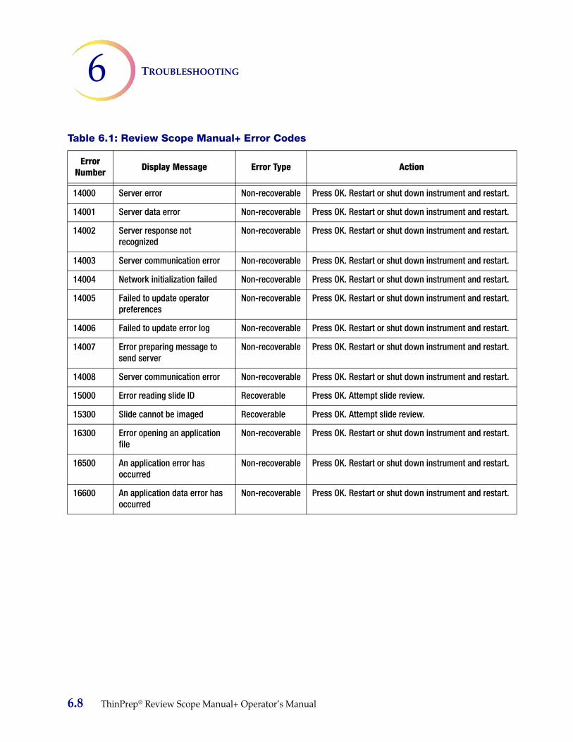
TROUBLESHOOTING6
14000 Server error Non-recoverable Press OK. Restart or shut down instrument and restart.
14001 Server data error Non-recoverable Press OK. Restart or shut down instrument and restart.
14002 Server response not recognized
Non-recoverable Press OK. Restart or shut down instrument and restart.
14003 Server communication error Non-recoverable Press OK. Restart or shut down instrument and restart.
14004 Network initialization failed Non-recoverable Press OK. Restart or shut down instrument and restart.
14005 Failed to update operator preferences
Non-recoverable Press OK. Restart or shut down instrument and restart.
14006 Failed to update error log Non-recoverable Press OK. Restart or shut down instrument and restart.
14007 Error preparing message to send server
Non-recoverable Press OK. Restart or shut down instrument and restart.
14008 Server communication error Non-recoverable Press OK. Restart or shut down instrument and restart.
15000 Error reading slide ID Recoverable Press OK. Attempt slide review.
15300 Slide cannot be imaged Recoverable Press OK. Attempt slide review.
16300 Error opening an application file
Non-recoverable Press OK. Restart or shut down instrument and restart.
16500 An application error has occurred
Non-recoverable Press OK. Restart or shut down instrument and restart.
16600 An application data error has occurred
Non-recoverable Press OK. Restart or shut down instrument and restart.
Table 6.1: Review Scope Manual+ Error Codes
Error Number Display Message Error Type Action
6.8 ThinPrep® Review Scope Manual+ Operator’s Manual

7. Service In
form
ation
7. S
ervi
ce In
form
atio
n

7SERVICE INFORMATION
C h a p t e r S e v e n
Service Information
Corporate AddressHologic, Inc.
250 Campus Drive
Marlborough, MA 01752 USA
Business HoursHologic’s business hours are 8:30 a.m. to 5:30 p.m. EST Monday through Friday, excluding holidays.
Customer ServiceProduct orders, which include standing orders, are placed through Customer Service by phone during business hours at 1-800-442-9892 Option 5 or 508-263-2900.
Orders can also be faxed to the attention of Customer Service at 508-229-2795.
WarrantyA copy of Hologic’s limited warranty and other terms and conditions of sale may be obtained by contacting Customer Service at the numbers listed above.
Technical Support
For questions about ThinPrep® Review Scope Manual+ issues and related application issues, repre-sentatives from Technical Support are available by phone 7:00 a.m. to 7:00 p.m. EST Monday through Friday at 1-800-442-9892 Option 6 or 508- 263-2900.
Service contracts can also be ordered through Technical Support.
Protocol for Returned GoodsFor returns on warranty-covered ThinPrep Review Scope Manual+ accessory and consumable items, contact Technical Support.
ThinPrep® Review Scope Manual+ Operator’s Manual 7.1

SERVICE INFORMATION7
This page intentionally left blank.
7.2 ThinPrep® Review Scope Manual+ Operator’s Manual

8. Ord
ering
In
form
ation 8.
Ord
erin
g
Info
rmat
ion

8ORDERING INFORMATION
C h a p t e r E i g h t
Ordering Information
Mailing AddressHologic, Inc.
250 Campus Drive
Marlborough, MA 01752 USA
Remittance AddressHologic, Inc.
PO Box 3009
Boston, MA 02241-3009 USA
Business HoursHologic’s business hours are 8:30 a.m. to 5:30 p.m. EST Monday through Friday, excluding holidays.
Customer ServiceProduct orders, which include standing orders, are placed through Customer Service by phone during business hours at 1-800-442-9892 Option 5 or 508-263-2900.
Orders can also be faxed to the attention of Customer Service at 508-229-2795.
WarrantyA copy of Hologic’s limited warranty and other terms and conditions of sale may be obtained by contacting Customer Service at the numbers listed above.
Protocol for Returned Goods
For returns on warranty-covered ThinPrep® Review Scope Manual+ accessory and consumable items, contact Technical Support.
ThinPrep® Review Scope Manual+ Operator’s Manual 8.1
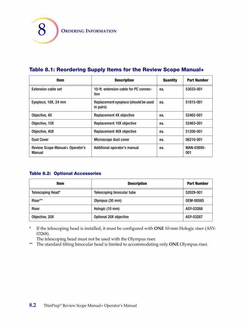
ORDERING INFORMATION8
* If the telescoping head is installed, it must be configured with ONE 10-mm Hologic riser (ASY-03268).The telescoping head must not be used with the Olympus riser.
** The standard tilting binocular head is limited to accommodating only ONE Olympus riser.
Table 8.1: Reordering Supply Items for the Review Scope Manual+
Item Description Quantity Part Number
Extension cable set 10-ft. extension cable for PC connec-tion
ea. 53033-001
Eyepiece, 10X, 24 mm Replacement eyepiece (should be used in pairs)
ea. 51815-001
Objective, 4X Replacement 4X objective ea. 52462-001
Objective, 10X Replacement 10X objective ea. 52463-001
Objective, 40X Replacement 40X objective ea. 51200-001
Dust Cover Microscope dust cover ea. 06210-001
Review Scope Manual+ Operator’s Manual
Additional operator’s manual ea. MAN-03695-001
Table 8.2: Optional Accessories
Item Description Part Number
Telescoping Head* Telescoping binocular tube 52029-001
Riser** Olympus (30 mm) OEM-00585
Riser Hologic (10 mm) ASY-03268
Objective, 20X Optional 20X objective ASY-03287
8.2 ThinPrep® Review Scope Manual+ Operator’s Manual

Ind
ex Ind
ex

INDEX
Index
10X objective 1.6, 8.210X objective position sensor 1.640X objective 1.6, 8.24X objective 1.6, 8.2
AAccessories 8.2administrative options 3.4Auto Locate 4.10Auto Locate speed 3.17Auto Review 4.1Auto Scan 1.3, 4.14Auto Scan direction 3.11Auto Scan overlap 3.11Auto Scan preference settings 3.11Auto Scan type 3.11automatic start/stop Auto Scan 3.13
Bbeep volume 3.19
Ccellularity check 4.13collector 1.6, 5.2component overview 1.6computer 2.5condenser 1.6, 5.2confirm slide ID 6.3controller 2.4Customer Service 7.1, 8.1
ThinPrep® Review Scope Manual+ Operator’s Manual Index.1

INDEX
Ddefault preferences 3.21dimensions 1.7dust cover 8.2
EEntering Slide IDs 3.5Entering the slide ID 3.5error messages 6.5extended shutdown 2.11eyepieces 1.6, 2.5, 8.2
Ffiducial mark 1.8field of view 1.4, 4.10focus knobs 1.6fuses 1.9
Hhazards 1.11head
telescoping 2.5trinocular 2.5
humidity range 1.8
IImaging process 1.4Installation 2.1
Index.2 ThinPrep® Review Scope Manual+ Operator’s Manual

INDEX
KKoehler alignment 5.2
Llabels, location on instrument 1.13light intensity adjustment knob 1.6login 3.9
Mmain menu 3.10manual entry of a slide ID 6.2Manual Review 4.1Manual+ Auto Scan 3.16mark 1.3Mark function 4.6mark indicator 3.20, 4.11materials required 4.4microscope 2.5microscope slide 1.8
NNext function 4.6non-recoverable errors 6.4normal shutdown 2.10nosepiece 1.3
ThinPrep® Review Scope Manual+ Operator’s Manual Index.3

INDEX
Oobject of interest 1.4objective 1.3objectives, 4X, 10X, 40X 1.6, 2.5, 8.2Operator’s Manual 8.2Optical character recognition (OCR) 1.2ordering information 8.1
Pposition sensor, 10X objective 1.6power 1.9, 2.1power cable 1.9power on self test (POST) 1.10power switch
computer 1.6, 2.8microscope 1.6, 2.8
Previous function 4.6
Rread slide ID 4.8recoverable errors 6.4reset preferences to default 3.21restart the Review Scope Manual+ 6.5review control 1.6, 4.5review control, adjust 2.7review marks 4.13
Index.4 ThinPrep® Review Scope Manual+ Operator’s Manual
INDEX
Ssafety standards 1.9screwdriver (on board) 1.6, 2.7Semiautomatic start/stop Auto Scan 3.14shutdown 2.10slide data record 4.2slide ID mismatch 6.3slide review 4.1, 4.7slide review process 4.3Slide Search 3.5sound 3.19Specimen Adequacy 4.13specimen handling 1.5specimen preparation 1.5stage axis knob tension 2.7Stage Control 2.7stage, microscope, motorized 1.6subsequent review 1.3, 4.1system disabled screen 6.5system software version 2.9
TTechnical Support 7.1temperature range 1.8touch screen 2.6, 4.4Troubleshooting 6.1
UUser Interface 3.1user preferences 3.11
ThinPrep® Review Scope Manual+ Operator’s Manual Index.5

INDEX
Vvoltage 1.9volume (sound) 3.19
WWarnings 1.11weight 1.8, 2.2
Index.6 ThinPrep® Review Scope Manual+ Operator’s Manual

Op
erator’s Manual
ThinP
rep®
Review
Scop
e Manual+

MAN-03695-001 Rev. 002
Hologic, Inc.250 Campus Drive Marlborough, MA 01752 USA1-800-442-98921-508-263-2900www.hologic.com

ThinPrep® Review Scope Manual+ Quick Reference Guide
Review Scope Manual+ Components
Review Controls
Previous
(roll back) Next
(roll forward)
Mark
(press)
Touch Screen (example)Review Control with Scroll Wheel
Auto Scan modes - used when performing a full slide review
Automatic start/stop
The stage moves automatically
in discrete, overlapping fi elds of
view. The degree of overlap from
row to row and the speed of
stage movement are user-
adjustable. The user may pause
and resume stage motion.
Semiautomatic start/stop
The user prompts the stage
to advance to the next fi eld of
view. The degree of overlap
from row to row and the speed
of stage movement are user-
adjustable.
Manual+
The user manually moves the
stage within each row using
the stage control knob. The
degree of overlap from row
to row is user-adjustable. The
stage moves automatically be-
tween rows. No speed setting
is necessary.
Hologic, Inc. • 250 Campus Drive • Marlborough, MA 01752 USA • 1-800-442-9892 • 1-508-263-2900 • www.hologic.com
Hologic Ltd. • Heron House, Oaks Business Park • Crewe Road, Wythenshawe • Manchester, M23 9HZ, UK • Tel: +44 (0)161 946 2206
AW-10403-001 Rev. 002
Review Scope Manual+ may differ from the microscope frame style shown here.
Refer to the operator’s manual.
Eyepieces
Binocular Tube
Microscope
Power Switch
(on left side)
Touch Screen
Interface Computer
Revolving Nosepiece
(4X, 10X, 40X, plus
position sensor)
Motorized Stage
Light Intensity
Adjustment
Knob
Review Control Controller
Collector
Condenser
(under stage)
Computer
Power Switch
X, Y Axis Stage Control Knobs
(Stage Control Knobs)
Coarse/Fine
Focus Knob
(on left side)

Power Off1. Run Shut Down2. Power off microscope
Next Slide
Electronic MarksMade
No Electronic MarksMade
(Full Review)
Power On
User Login
Load Slide
Scan Slide ID
Locate Fiducial Marks
Auto Locate(22 fields of view)
Review Electronic Marks(optional)
Auto Scan(optional)
Auto Scan
Review Electronic Marks(optional)
Mark Slide Manually
Scan Slide ID
Locate Fiducial Marks
Update Slide Data Record
Unload Slide
1. Microscope2. Computer
Typical Slide Review Process Software Menu Overview
Start
PasswordProtected
User Preferences
Review Slide
System Errors
Slide Search
Language
Direction
Overlap
Auto Scan Type
Auto Locate Speed
Sound
Mark Indicator
Power On
LoginAdminOptions
ServiceManual Review
Read
Slide ID