Embed Size (px)
Citation preview

Thin Film Scattering:Epitaxial Layers
5th Annual SSRL Workshop on Synchrotron X-ray Scattering Techniques in Materials and Environmental Sciences: Theory and Application
June 1 - 3, 2010
Arturas VailionisGLAM, Stanford University
SIMES, SLAC

• Thin films. Epitaxial thin films
• What basic information we can obtain from x-ray diffraction
• Reciprocal space and epitaxial thin films
• Scan directions – reciprocal vs. real space scenarios
• Mismatch, strain, mosaicity, thickness
• How to choose right scans for your measurements
• Mosaicity vs. lateral correlation length
• SiGe(001) layers on Si(001) example
• Why we need channel analyzer
• What can we learn from reciprocal space maps
• SrRuO3 and La0.67Sr0.33MnO3 films example
• Summary

What is thin film/layer?
Material so thin that its characteristics are dominated primarily by two dimensional effects and are mostly different than its bulk propertiesSource: semiconductorglossary.com
A thin layer of something on a surfaceSource: encarta.msn.com
Material which dimension in the out-of-plane direction is much smaller than in the in-plane direction.

Epitaxial Layer
A single crystal layer that has been deposited or grown on a crystalline substrate having the same structural arrangement.Source: photonics.com
A crystalline layer of a particular orientation on top of another crystal, where the orientation is determined by the underlying crystal.
Homoepitaxial layerthe layer and substrate are the same material and possess the same lattice parameters.
Heteroepitaxial layerthe layer material is different than the substrate and usually has different lattice parameters.

Thin films structural types
Structure Type Definition
Perfect epitaxial Single crystal in perfect registry with the substrate that is also perfect.
Nearly perfect epitaxial Single crystal in nearly perfect registry with the substrate that is also nearly perfect.
Textured epitaxialLayer orientation is close to registry with the substrate in both in-plane and out-of-plane directions. Layer consists of mosaic blocks.
Textured polycrystalline Crystalline grains are preferentially oriented out-of-plane but random in-plane. Grain size distribution.
Perfect polycrystalline Randomly oriented crystallites similar in size and shape.
Amorphous Strong interatomic bonds but no long range order.
P.F. Fewster “X-ray Scattering from Semiconductors”
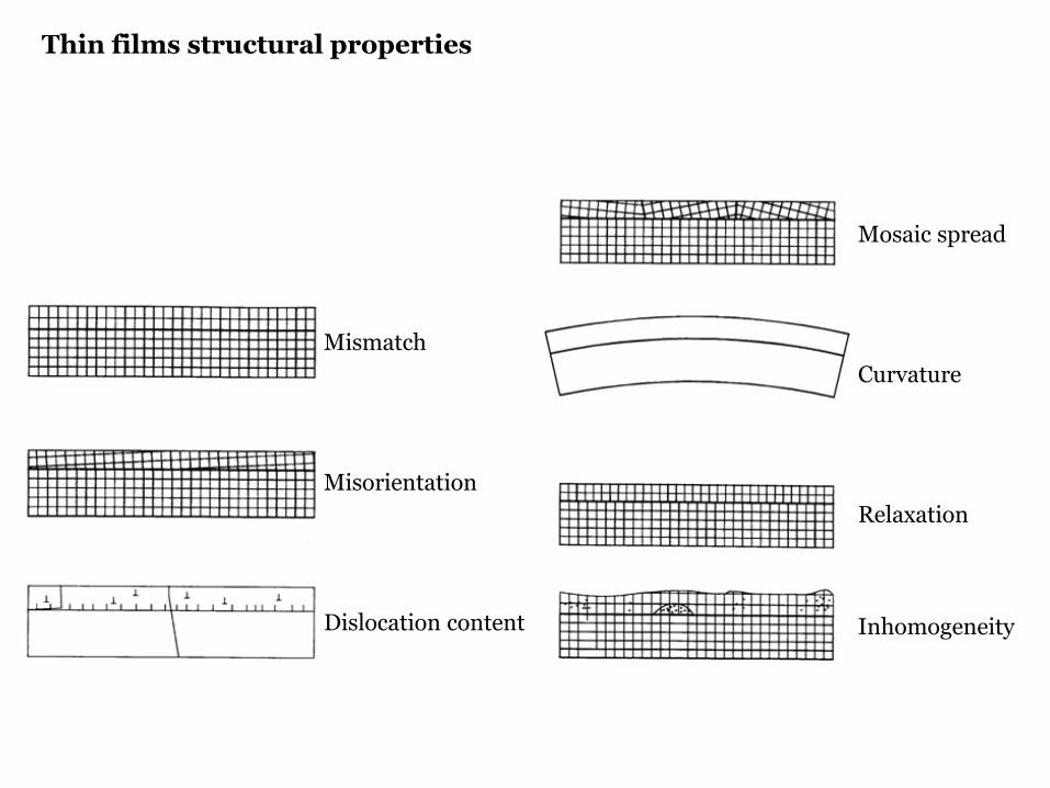
Mosaic spread
Curvature
Relaxation
Inhomogeneity
Mismatch
Misorientation
Dislocation content
Thin films structural properties

Crystalline state of the layers: Epitaxial (coherent with the substrate, relaxed) Polycrystalline (random orientation, preferred orientation) Amorphous
Crystalline quality
Strain state (fully or partially strained, fully relaxed)
Defect structure
Chemical composition
Thickness
Surface and/or interface roughness
What we want to know about thin films?

Thickness Composition Relaxation Distortion Crystalline size Orientation Defects
Perfect epitaxy × × ×Nearly perfect epitaxy × × ? ? ? × ×Textured epitaxy × × × × × × ×Textured polycrystalline × × ? × × × ?Perfect polycrystalline × × × × ?Amorphous × ×
P.F. Fewster “X-ray Scattering from Semiconductors”
Overview of structural parameters that characterize various thin films

Beforedeposition
AfterdepositionR
L
RLL
RL
RLL
zz ddd
aaa −
=−
==⊥⊥
⊥ εε
Tetragonal Distortion
Lattice mismatch betweencubic lattice parameters:
S
SRL
aaa
aa −
=∆
Lattice mismatch induces lattice strain:
RLa
RLa
SaSa
Lc
SL aa =
SaSa
RLa
RLa
SaSa
0≠∆φ
0=∆φ
Relaxed
Strained, coherent, pseudomorphic
Partially relaxed
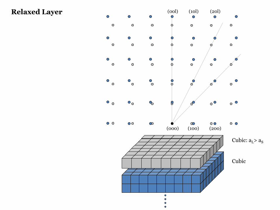
(000)
(00l)
(100)
(10l)
(200)
(20l)
Cubic: aL> aS
Cubic
Relaxed Layer

(000)
(00l)
(100)
(10l)
(200)
(20l)
Tetragonal:
CubicTetragonaldistortion
SL
SIIL
aaaa
>
=⊥
Strained Layer
Compressive strain

Cubic
Cubic
Cubic
Tetragonal
ReciprocalSpace
(000) (000)
(00l) (00l)
(hkl) (hkl)
aL > aS
Perfect Layers: Relaxed and Strained

Reciprocal space – Ewald sphere
θλθλ
sin22
121sin1 *
hklhkl
hkl dd
=→=== dOC
*hkldOB =

Incident beam
Diffracted beam Scattering
vectorhkl
hkl d1sin2 * ===
− dss 0
λθ
λλ
0ss −
λs
λ0s
θθθλ sin2 hkld=
Reciprocal Lattice Point
(000)
(00l)
(hkl)
SymmetricalScan
AsymmetricalScan
(000)
(00l)
(hkl)
(00l) scan
(h00) scan
(h00)
(-hkl)
(00l) scan
Relaxed Layer Strained Layer
Reciprocal space – Scattering vector

Scan Directions
Sample Surface
(00l)
Symmetrical Scanθ - 2θ scan
θθ
2θ
(hkl)
Asymmetrical Scanω - 2θ scan
αα = θ − ω
ω
2θ

Sample Surface
(00l)
(hkl)
Scan Directions
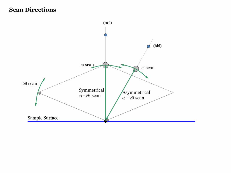
(00l)
(hkl)
Symmetricalω - 2θ scan
Asymmetricalω - 2θ scan
Sample Surface
2θ scan
ω scanω scan
Scan Directions

Compressive strain
L
S
Tensile strain d-spacing variation Mosaicity
Finite thickness effect
cL < aScL > aS
Real RLP shapes
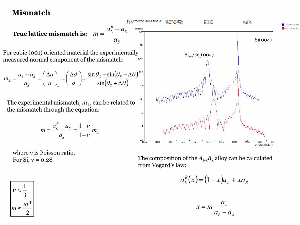
Mismatch
Si(004)
Si1-xGex(004)For cubic (001) oriented material the experimentally measured normal component of the mismatch:
The experimental mismatch, m⊥, can be related to the mismatch through the equation:
True lattice mismatch is:S
SRL
aaam −
=
where ν is Poisson ratio.For Si, ν = 0.28
2*
31
mm ≈
≈ν
( )( )θθ
θθθ∆+
∆+−=
∆
=
∆
=−
=⊥
⊥⊥
S
SS
S
S
dd
aa
aaam
sinsinsin
⊥+−
=−
= ma
aamS
SRL
νν
11
The composition of the A1-xBx alloy can be calculated from Vegard’s law:
( ) ( ) BARL xaaxxa +−= 1
AB
A
aaamx−
=

Substrate Layer SeparationS-peak: L-peak: Separation: Omega(°) 34.5649 Omega(°) 33.9748 Omega(°) 0.590172Theta(°) 69.1298 2Theta(°) 67.9495 2Theta(°) 1.18034
Layer ThicknessMean fringe period (°): 0.09368 Mean thickness (um): 0.113 ± 0.003
2Theta/Omega (°) Fringe Period (°) Thickness (um) _____________________________________________________________________________
66.22698 - 66.32140 0.09442 0.11163766.32140 - 66.41430 0.09290 0.11352866.41430 - 66.50568 0.09138 0.11548166.50568 - 66.59858 0.09290 0.11364866.59858 - 66.69300 0.09442 0.11187866.69300 - 66.78327 0.09027 0.117079
Interference fringes observed in the scattering pattern, due to different optical paths of the x-rays, are related to the thickness of the layer:
( )( )21
21
sinsin2 ωωλ
−−
=nnt
Layer Thickness

(000)
(00l)
(hkl)
Partially Relaxed + Mosaicity
(000)
(00l)
(hkl)
Partially Relaxed + Thin

(000)
(00l)
ω direction
ω-2θ direction
Mosaicity
Defined by receiving optics (e.g. slits) Defined by incident
optics – monochromator
S
L
Symmetrical scan

(000)
(00l)
ω direction
ω-2θ direction
Symmetrical Scan
receivingslit
analyzercrystal
mosaicity
receivingslit
analyzercrystal
d-spacing variation

Ge content: 50% 40% 30% 20% 10%
Triple axis diffractometry
Open detector
Triple axis
Open detector
Triple axis

(000)
(00l)(hkl)
SymmetricalScan
AsymmetricalScan
(000)
(00l)
(hkl)
(00l) scan
(h00) scan(h00)
ω-scan
ω-2θ scan
h-scan
l-scan

Relaxed SiGe on Si(001)
Shape of the RLP might provide much more information
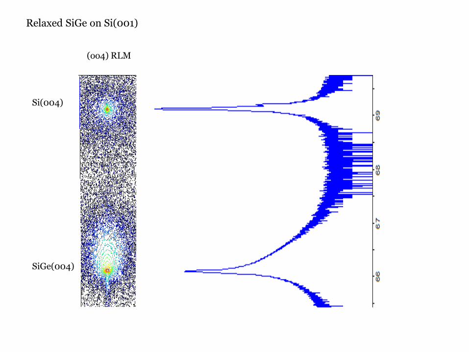
Relaxed SiGe on Si(001)
(oo4) RLM
Si(004)
SiGe(004)

(004) (113)
(000)
(00l)(hkl)
ω-scan
ω-2θ scan

100×−−
=S
RL
SL
aaaaR
The relaxation is defined as:
Relaxation
Grazing incidence Grazing exit Symmetrical scan
To separate the layer tilt from the true splitting we can make grazing incidence and grazing exit measurements:
The effect of tilt on the peak splitting is reversed if the specimen is rotated by 180o about its surface normal.
The splitting due to mismatch will not be affected by such rotation
ϕθθ ∆+∆=∆ gi– grazing incidence
– grazing exitϕθθ ∆−∆=∆ ge
giθ∆ geθ∆ symθ∆
ϕθ −BBθ2 ϕθ +B Bθ2
Bθ2Bθ

Relaxation
Considering (tetragonal distortion):
φφφθθθ
∆+=∆+=
SL
SL
φ – angle between reflecting plane and the surface
LLL cba ≠=
we obtain cell constants for the (00l )-oriented layer:
2
22
sin2
cossin2
lkhla
lc
LL
LLL
+=
=
θλ
φθλ
−−
−−
=
νν
νν
121
12 LL
RL
aca

The Mosaic Spread and Lateral Correlation Length functionality derives information from the shape of a layer peak in a diffraction space map recorded using an asymmetrical reflection
L
qz
L3
L2
L1∆qx
∆qzξ
ϕ
( )ξϕξ+
−=cos
cos
2
1
LL
ξϕ
cossin
2
3 −=LL
∆∆
=
=
∆+∆=
z
x
z
x
zx
qqL
tan
1
tan
1
223
ξ
ϕand
Lateral correlation length
222
1
1
zx qqL
L
+=
=
Microscopic tilt
qx
(000)
Analysis of Laterally Inhomogeneous Layers
∆ω

L
qz
(000)
∆qx1
∆qx2
∆ω
Analysis of Laterally Inhomogeneous Layers
21
2
2
1
1
11
2tan
2
2tan
2
xLxL
z
x
z
x
qqL
∆=
∆=
∆=
∆=∆
ωω
ω
If the contributing profiles have Gaussian shape:
21
21
212
122
21
222
1
222
1
ω
ω
ω
xx
zzz
xxx
xLnnxxn
qqL
qqq
qqq
qqq
∆−∆=
+∆−∆
=∆
∆+∆=∆
Two symmetrical reflections

Λ
t dhkl
Superlattices and Multilayers
Substrate

6
(000)
(00l)
10
(000)
(00l)
2
(000)
(00l)
4
(000)
(00l)
Superlattices and Multilayers

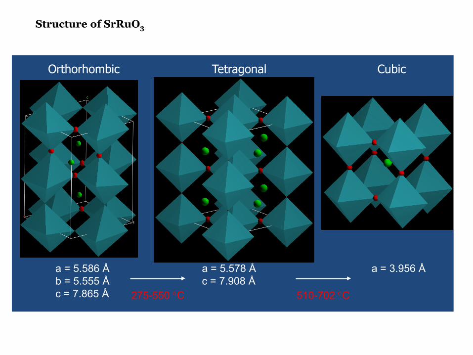
a = 5.586 Åb = 5.555 Åc = 7.865 Å
a = 5.578 Åc = 7.908 Å
a = 3.956 Å
275-550 °C 510-702 °C
Orthorhombic Tetragonal Cubic
Structure of SrRuO3

[1-10]
[110]
NGOLayer
3.85 3.86 3.87 3.88 3.89 3.90 3.91 3.92 3.93 3.94 3.95 3.96
SrTi
O3
NdG
aO3
LSA
T
La0.
67Sr
0.33
MnO
3
SrR
uO3
DyS
cO3
Pseudo-cubic lattice parameters:
Samples:
SrRuO3 on SrTiO3 and DyScO3
La0.67Sr0.33MnO3 on NdGaO3, LSAT, SrTiO3 and DyScO3
a b
c
γ
[1-10]
[110]
STOLayer
[100]
[001]

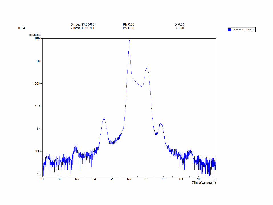
SrTiO3 (002)SrRuO3 (220)
Finite size fringes indicate well ordered films
ω – 2θ symmetrical scans
1.E+02
1.E+03
1.E+04
1.E+05
1.E+06
1.E+07
1.E+08
1.E+09
1.E+10
1.E+11
1.8 1.85 1.9 1.95 2 2.05 2.1 2.15 2.2
H-K (rlu)
Inte
nsity
(a.u
.) LSMO(220)
SrTiO3 (002)
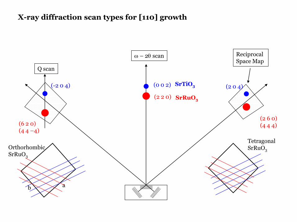
(2 6 0)(4 4 4)(6 2 0)
(4 4 –4)
(2 2 0)
(0 0 2)(-2 0 4) (2 0 4)
ω – 2θ scan Reciprocal Space Map
Q scan
SrTiO3
SrRuO3
ab
OrthorhombicSrRuO3
TetragonalSrRuO3
X-ray diffraction scan types for [110] growth

(0 0
1)
(1 -1 0)
a b
c
γ
Untwinned
(0 0
1)
+ (
1 -1
0)
(1 -1 0) + (0 0 1)
Twinned
Twinning in SrRuO3/SrTiO3

ab
OrthorhombicSrRuO3
(260) (444) (620) (444)
High-Resolution Reciprocal Area Mapping
Substrate
Layer
Orthorhombic to Tetragonal Transition

Orthorhombic
Tetragonal
Cubic
Literature: 510-702 °C
Transition Orthorhombic to Tetragonal ~ 350 °C
Appl. Phys. Lett. 91, 071907 (2007)
O – T Structural Transition, (620) & (260) reflections

Temperature ( oC)
150 200 250 300 350 400
Inte
nsity
(arb
uni
ts)
0.0
0.2
0.4
0.6
0.8
1.0
O – T Structural Transition, (221) reflection
Orthorhombic
Tetragonal
Cubic
Literature: 510-702 °C
Transition Orthorhombic to Tetragonal ~ 310 °C
O – TTransition
(221) Peak
Orthorhombic Present
Tetragonal Absent
Appl. Phys. Lett. 91, 071907 (2007)

Appl. Phys. Lett. 93, 051909 (2008)

Compressive Stress Unit cell is orthorhombica ≠ b
a b
c
γ

Tensile Stress Unit cell is tetragonala = b
a b
c
γ

89.0
89.5
90.0
90.5
91.0
91.5
92.0
92.5
5.45
5.46
5.47
5.48
5.49
5.50
5.51
5.52
NGO LSAT STO DSO
γan
gle
(deg
)
aan
d b
latt
ice
par
amet
ers
(Å)
a b γ
C C T T[110] γ angle accommodates the stress along [1-10]
[1-10]
γ
a b
Substrate a (Å) b (Å) ab (Å) c (Å) Layer a (Å) b (Å) ab (Å) c (Å) γ (O)
NdGaO3 5.428 5.498 7.726 7.708 LSMO/NGO 5.477 5.513 7.725 7.707 89.32
LSAT 5.476 5.476 7.744 7.740 LSMO/LSAT 5.471 5.507 7.744 7.740 89.72
SrTiO3 3.905 LSMO/STO 5.480 5.483 7.809 7.809 90.87
DyScO3 5.444 5.721 7.897 7.904 LSMO/DSO 5.478 5.483 7.895 7.902 92.16
LSMO (O) 5.488 5.524 7.762 7.787
Strain (%)
NdGaO3 LSAT SrTiO3 DyScO3
along ab = -0.79along c = -1.02
along ab = -0.55along c = -0.60
along ab = 0.28along c = 0.28
along ab = 1.39along c = 1.48
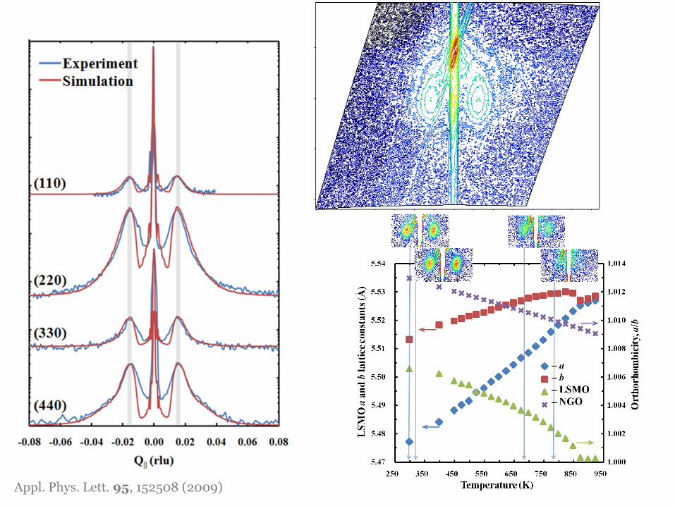
Appl. Phys. Lett. 95, 152508 (2009)
Summary
Reciprocal space for epitaxial thin films is very rich.
Shape and positions of reciprocal lattice points with respect to the substrate reveal information about:
• Mismatch• Strain state• Relaxation• Mosaicity• Composition• Thickness ….
Diffractometer instrumental resolution has to be understood before measurements are performed.

PolycrystallinePreferred orientationSingle crystal