Embed Size (px)
Citation preview

Thilo Pauly, CERN/PH, LECC Heidelberg 2005 Sept 13, 2005
ATLAS Level-1 Trigger Timing-In Strategies
On behalf of
S. Ask1), P. Borrego Amaral1), N. Ellis1), P. Farthouat1), P. Gallno1), J. Haller1), A. Krasznahorkay1)2), T. Maeno1),
T. Pauly1), H. Pessoa Lima Jr.3)4), I. Resurreccion Arcas1),
G. Schuler1), J. M. de Seixas3), R. Spiwoks1), R. Torga Teixeira1), T. Wengler1)
1) CERN, Switzerland2) University of Debrecen, Hungary3) Federal University of Rio de Janeiro, Brazil4) Brazilian Center for Research in Physics, Brazil

Thilo Pauly, CERN/PH, LECC Heidelberg 2005 2Sept 13, 2005
Timing Concept in the Trigger System
Synchronous
Asynchronous
Identifier-based(L1ID, BCID)
Timing-based
(Subject of this talk)
TriggerDelay
L1ADelay
Thilo Pauly, CERN/PH, LECC Heidelberg 2005 3Sept 13, 2005
USA 15
•Time of flight (bunches every 25ns = 7.5m)•Detector response•Cable lengths (10m = 100ns)
The Problem
Need well-defined procedures to do the timing-in.
BC 2
BC 1
BC 1

Thilo Pauly, CERN/PH, LECC Heidelberg 2005 4Sept 13, 2005
Overview
• Timing Signals at ATLAS– Distribution– Local Trigger Processor– Timing Tasks
• ATLAS Timing-In Strategy:– Test Pulses Decent initial timing– Beam Pick-Up Detectors
Filled-Bunch Trigger Bunch-Crossing Trigger
• NEW: Read-out of the Beam Pick-Up Detectors– Beam Pick-up Signal– Global BC Identification with Filled-Bunch Trigger– Clock phase: Read-out system, test results
• Conclusions
Thilo Pauly, CERN/PH, LECC Heidelberg 2005 5Sept 13, 2005
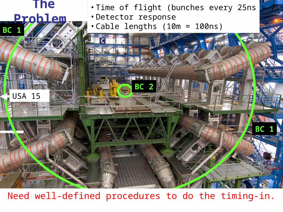
Timing Signals from the CTP
• Level-1 Accept (L1A) • BC = Bunch Clock with 40.08 MHz• Orbit Signal:
– 1 μs long pulse every revolution (89 μs)– Is used as bunch counter reset (BCR) to synchronise the
BC counters in the sub-detector front-ends, i.e. BCID– An LHC cycle consists of 3 564 bunches, each uniquely
identified by a BCID number.
– As reference point the abort gap in the bunch train can be used.

Thilo Pauly, CERN/PH, LECC Heidelberg 2005 6Sept 13, 2005
Distribution of Timing Signals
•CTP distributes L1A, BC, Orbit through CTP_OUT
(see R. Spiwoks “The ATLAS Level-1 Central Trigger Processor”)
•Local Trigger Processor (LTP):– Interface to CTP when running in
global mode– Important tool for sub-system
timing-in– Replaces the CTP when running in
local mode (test-pulses)•Via the TTC system (Timing,
Trigger and Controls)•New Multiplexer Module for
combining partitions
CTPUp to 20 Links
Partitions

Thilo Pauly, CERN/PH, LECC Heidelberg 2005 7Sept 13, 2005
Local Trigger Processor
CTP
Local
CalibrationRequest
TriggerType
LTP2
Interface to CTP+
CTP Replacement for Local Mode
(Local Inputs, Pattern Generator)
+Programmable Switch
Manual: ATL-DA-ES-0033
max 30 m
TTC

Thilo Pauly, CERN/PH, LECC Heidelberg 2005 8Sept 13, 2005
Typical Timing TasksSub-detector-specificTiming Tasks
Global TimingAdjustments
BC Counterfor BCID
Processing
TTCDistribution
Data Forming (Phase between BC & Signal)
Data Alignment (in steps of 25ns)
BC Identification(BCR delay)
Triggered BCIdentification(L1A delay)
BC
BCR
L1A
Sub-detector

Thilo Pauly, CERN/PH, LECC Heidelberg 2005 9Sept 13, 2005
Scenarios for Timing-In
• Timing-in with test-pulses:– Local mode: Stand-alone sub-detector timing-in, without
the CTP, only with LTP– Global mode with CTP
Will already give a decent initial timing set-up (up to a few bunch crossings)
• Single Beams: – Beam pick-ups to see filled bunches– CTP can be programmed to trigger on specific filled
bunches: filled-bunch trigger, bunch-crossing trigger
• Collisions:– Scintillation-counter hodoscopes in front of the end-cap
calorimeter– Coincidence between the two ends will give minimum
bias trigger (also combination with bunch-crossing trigger)
Thilo Pauly, CERN/PH, LECC Heidelberg 2005 10Sept 13, 2005
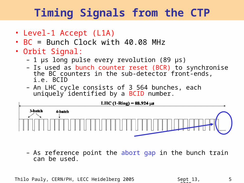
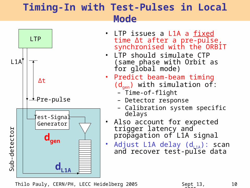
Timing-In with Test-Pulses in Local Mode
• LTP issues a L1A a fixed time Δt after a pre-pulse, synchronised with the ORBIT
• LTP should simulate CTP (same phase with Orbit as for global mode)
• Predict beam-beam timing (dgen) with simulation of:– Time-of-flight– Detector response– Calibration system specific
delays• Also account for expected trigger
latency and propagation of L1A signal
• Adjust L1A delay (dL1A): scan and recover test-pulse data
Test-SignalGenerator
dgen
dL1A
LTP
Pre-pulse
L1A
Δt
Sub
-dete
ctor

Thilo Pauly, CERN/PH, LECC Heidelberg 2005 11Sept 13, 2005
Timing-In with Test-Pulses in Global Mode
• Central Trigger Processor (CTP) triggers on a fixed BCID.
• LTP now in transparent mode• BC identification by comparing
BCIDs of event fragments in the read-out events (BCR offsets)
• Good initial timing setup for beam-beam collisions (up to a few bunch crossings)
• Leaves only the global timing to be established later:– Single beams: global BCR delay– Collisions: clock phase, global
L1A
Test-SignalGenerator
LTP
Test-SignalGenerator
LTP
CTP

Thilo Pauly, CERN/PH, LECC Heidelberg 2005 12Sept 13, 2005
Timing-In With Beam
• Need to “see” the bunches• BPTX = Beam position monitors
for timing purposes• Timing reference wrt bunches• 1 per incoming beam, 175 m
from IP• Electro-static button electrodes• Read-out currently under study

Thilo Pauly, CERN/PH, LECC Heidelberg 2005 13Sept 13, 2005
Usage of the BPTX Signal
BPTX are very powerful:1. Filled-bunch trigger, Bunch-crossing trigger2. Very precise time reference (clock monitoring)
“TTCMachine
Interface”
BC-Ref
BC-RF1
BC-RF2
BPTXRead-outSystem
(Oscilloscopes+ Computer)
BC-RefOrbitBC-RF1BC-RF2
BPTX1/2
Optical Electrical
Apps
Database
Configuration/Steering
Discr. CTP
USA15Electrical
Orbit
200m
(few ns)
(20 ps)
Filled-Bunch Trigger
Monitoring

Thilo Pauly, CERN/PH, LECC Heidelberg 2005 14Sept 13, 2005
Usage of the BPTX Signal
1) Filled-bunch trigger: Global BC Identification
Trigger input for CTP for filled-bunch trigger (Discrimination of the bunch signals by preserving the time information of each bunch at the level of a few ns)
Detection of gaps in the bunch train with CTP bunch-to-bunch scalers of trigger inputs (CTPMON)
BCID
BC=0

Thilo Pauly, CERN/PH, LECC Heidelberg 2005 15Sept 13, 2005
Usage of the BPTX Signal
2)Clock Monitoring:• Check the phase of each individual
bunch with the phase of the clock (accuracy: ~20ps)
• Monitoring of the clock from the machine. Detection of clock drift, due to
Problems in the signal chain Temperature drifts in optical fibres
• Check for satellite bunches in RF buckets (2.5ns)
• Monitoring frequency ~ once per minute

Thilo Pauly, CERN/PH, LECC Heidelberg 2005 16Sept 13, 2005
Expected BPTX Signal
• Very clean signal +20V ... -10V on 50Ω per button (from calculation, no transmission line yet)
• After transmission line: 20% of amplitude• Simple discrimination:
– Zero-crossing independent of bunch intensity– Zero-crossing depends on bunch length: – Bunch length fluctuations at 7 TeV will be %-level
Nominal LHC intensity: 1.15 x 10¹¹ p/bunch
7 TeV

Thilo Pauly, CERN/PH, LECC Heidelberg 2005 17Sept 13, 2005
Information in the BPTX Signal
– Complete signal description exists, and can be used as a fit function. Fit parameters:
• t0 Time of closest approach of bunch to BPTX,
•N Number of protons in bunch
•σ Bunch length (Gaussian σ)
– Background is expected to be small and under control (noise, reflections, etc.)

Thilo Pauly, CERN/PH, LECC Heidelberg 2005 18Sept 13, 2005
Clock Phase wrt LHC Bunches
• Resolution to be 20 ps• NEW: Read-out with oscilloscopes
– Relatively cheap (several 10 kCHF), no hardware and low-level software development
– Guaranteed support– Signal is fully visible, no signal discrimination
before read-out: necessary for debugging– Usually maximum of 4 Channels: 2 scopes
required for 6 signals. For instance:• Scope 1: Orbit, BC-Ref, BC-RF1, BPTX1• Scope 2: Orbit, BC-Ref, BC-RF2, BPTX2

Thilo Pauly, CERN/PH, LECC Heidelberg 2005 19Sept 13, 2005
Test system with Tektronix TDS 3054B
– 5 GS/s real-time sampling rate, i.e. measurements every 200ps
– Memory depth: 10k, i.e. 2μs (Read out 45 chunks of 2μs)
– Max voltage on 50Ω: 5VRMS with peaks < ±30V– 8-bit vertical resolution, ~0.3%– 4 channels– Trigger on long-gap with hold-off time to
88.924μs-x (with x < 2.75μs)– BPTX Test signal: Shaped output from a
pattern generator (Local Trigger Processor)– Built-in ethernet port: configuration and read-
out through HTTP1.1– Data analysis with ROOT and MINUIT
Thilo Pauly, CERN/PH, LECC Heidelberg 2005 20Sept 13, 2005
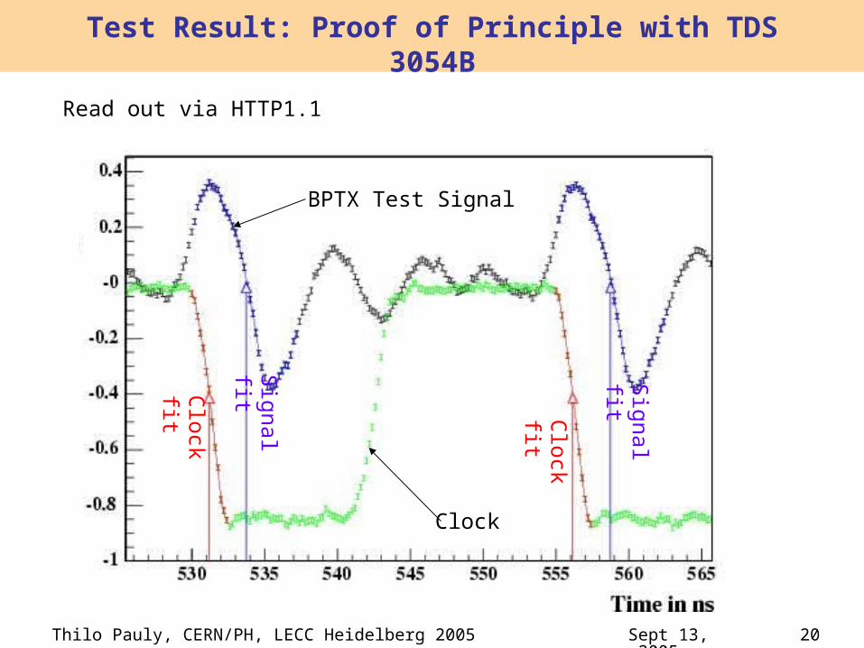
Test Result: Proof of Principle with TDS 3054B
Clock
BPTX Test Signal
Clo
ck fit Clo
ck fit
Sig
nal
fit Sig
nal
fit
Read out via HTTP1.1

Thilo Pauly, CERN/PH, LECC Heidelberg 2005 21Sept 13, 2005
•BPTX resolutions:Toy-Simulation, 1000 samples, TDS3054B resolutions (vertical resolution: 0.2V)t0 = 0 ± 2.6psσ = 252ps ± 3.0psN = (1.150 ± 0.015) x 1011
t0 uncorrelated to σ, NCorrelation between σ and N: 0.68
Test Result: Resolutions
•Clock Phase resolution:– Difference of two consecutive
clock signals– Resolution of phase
measurement: 20ps– Resolution of single time
measurement: 20ps/√2 = 14ps
Measured
Simulated

Thilo Pauly, CERN/PH, LECC Heidelberg 2005 22Sept 13, 2005
BPTX Read-Out: Conclusions
• The read-out requirements for the ATLAS BPTX can be fulfilled with 2 modern off-the-shelf sampling oscilloscopes with:– 4 channels each– Sampling rate ≥ 5 GS/sec– Memory deep enough to accommodate
89μs– Communication via ethernet

Thilo Pauly, CERN/PH, LECC Heidelberg 2005 23Sept 13, 2005
Conclusion
• I have presented strategies for timing in the sub-detectors– With test-pulses in local and global mode a
good initial timing setup can be achieved: up to a few bunch crossings
• ATLAS beam pick-up detectors are very powerful for timing-in with beam:– Filled-bunch trigger: Global BC
identification– Measuring and monitoring of the clock
phase wrt LHC bunches

Thilo Pauly, CERN/PH, LECC Heidelberg 2005 24Sept 13, 2005
Backup slides

Thilo Pauly, CERN/PH, LECC Heidelberg 2005 25Sept 13, 2005
Minimum-bias trigger:One hodoscope plane on each side replacing part of the JM moderator between Inner Detector and LAr
Scintillator Counter Hodoscope
η coverage: z = ± 3.5 m~25 cm < R <
~115 cm ~1.8 < η < ~3.3
φ segmentation: probably 8
Very high efficiency for minimum bias events

Thilo Pauly, CERN/PH, LECC Heidelberg 2005 26Sept 13, 2005
The CTP is timed-in using the beam pick-ups as timing
reference:
• CTP can generate triggers with a fixed latency for specific bunch crossings using the beam pickups
• Using the scintillatior hodoscopes, the CTP can restrict triggers to crossings with interactions
Timing-In CTP Using the Beam Structure
Adjustoffset
BCID LHC
BCID CTP

Thilo Pauly, CERN/PH, LECC Heidelberg 2005 27Sept 13, 2005
1) Sub-detector chooses a quantity with high rate due to
interaction products and small background from other
sources
2) Map out the LHC bunch structure by plotting activity vs.
BCID using random triggers or scanning all BCID values with
L1As
3) Compare to (known) LHC bunch structure, e.g. position of
long gap
Timing Check Using the Beam Structure
Adjust for offsets
But: this procedure can take several days for certain sub-detectors with low rate and acceptance.

Thilo Pauly, CERN/PH, LECC Heidelberg 2005 28Sept 13, 2005
Global BC Identification with Filled-Bunch Trigger
• Discriminate BPTX signal (at the ns level)• Propagation of BPTX signal into CTP is
known• ToF from BPTX position to z=0 is known• CTP has scalers for each PIT bit and each
single bunch: find abort gap for the BPTX trigger signal
BC=0
BCID
Thilo Pauly, CERN/PH, LECC Heidelberg 2005 29Sept 13, 2005
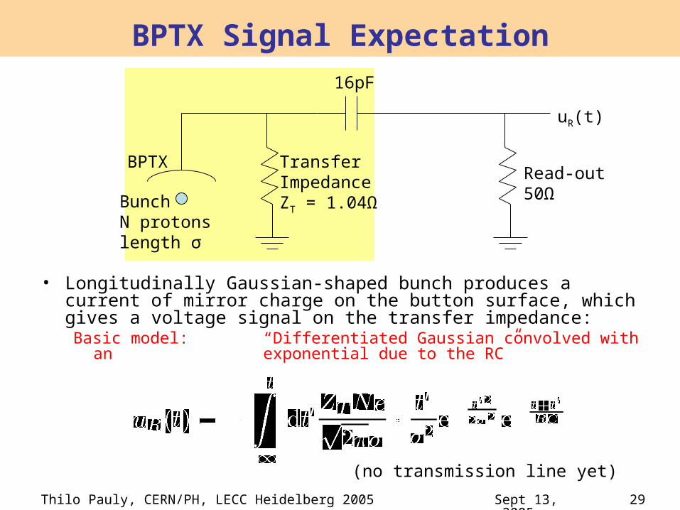
BPTX Signal Expectation
• Longitudinally Gaussian-shaped bunch produces a current of mirror charge on the button surface, which gives a voltage signal on the transfer impedance:Basic model: “Differentiated Gaussian convolved with
an exponential due to the RC”
TransferImpedanceZT = 1.04Ω
Read-out50Ω
BPTX
BunchN protonslength σ
16pF
uR(t)
(no transmission line yet)

Thilo Pauly, CERN/PH, LECC Heidelberg 2005 30Sept 13, 2005
Expected BPTX Signal
• Very clean signal +20V ... -10V on 50Ω per button (from calculation, no transmission line yet)
• Zero-crossing independent of bunch intensity• Zero-crossing depends on bunch length:
– 100ps effect between injection and 7 TeV– Bunch length fluctuations at 7 TeV will be %-level
Nominal LHC intensity: 1.15 x 10¹¹ p/bunch At Injection
At 7 TeV
7 TeV 5 x 10⁹ p/bunch

Thilo Pauly, CERN/PH, LECC Heidelberg 2005 31Sept 13, 2005
Acquisition Mode/Scope Trigger
• Acquisition modes:– Real-time sampling (single shot, averaging mode)
– Equivalent-time sampling (only for repetitive signals)
• Different trigger possibilities:– For a real-time single shot mode, any trigger can be used: whole
bunch train is read out.– For averaging or equivalent-time sampling, a trigger signal with
small jitter is needed. Possibilities:• Orbit signal• Combination: First Orbit, then clock edge• BPTX signal itself, with trigger hold-off time set to find particular gaps
in the bunch train