Embed Size (px)
Citation preview
Master report, IDE 1221, June 2012
Subject: Master Thesis in Embedded and intelligent
system
Peer to Peer VoIP over IEEE 802.11
WLAN
Mast
er
thesi
s Sch
oo
l o
f In
form
ati
on
Sci
en
ce, C
om
pu
ter
an
d E
lect
rica
l En
gin
eeri
ng
Chandrashekar Reddy Palle, Ashwin Mantoor &
Karunakar Antham
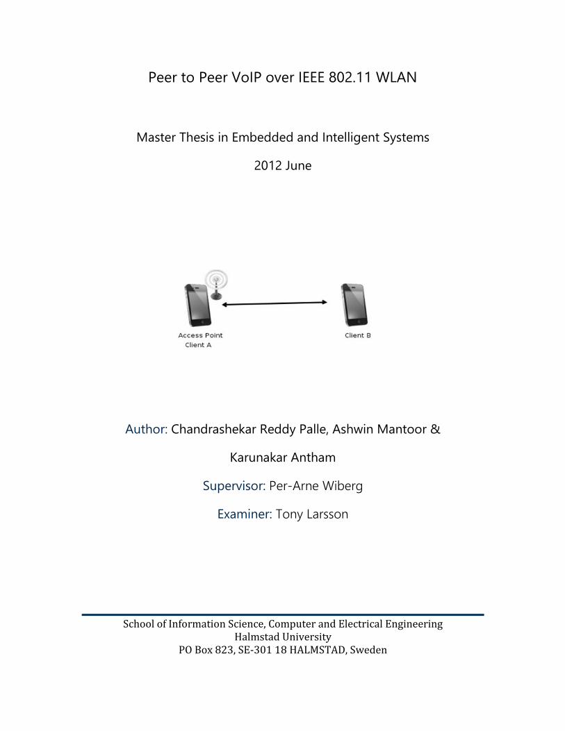
Peer to Peer VoIP over IEEE 802.11 WLAN
Master Thesis in Embedded and Intelligent Systems
2012 June
Author: Chandrashekar Reddy Palle, Ashwin Mantoor &
Karunakar Antham
Supervisor: Per-Arne Wiberg
Examiner: Tony Larsson
School of Information Science, Computer and Electrical Engineering
Halmstad University PO Box 823, SE-301 18 HALMSTAD, Sweden
I
Description of cover page picture: On the Cover page, the Figure Group formation between Client-A and Client B is shown. Here Client A and Client B are Android devices. Client A is acting like an Access-point and Client B connected to it for forming a group to make VoIP calls over WLAN to each other.
© Copyright Chandrashekar Reddy Palle, Ashwin Mantoor & Karunakar Antham , 2012. All rights reserved Master Thesis Report, IDE1221 School of Information Science, Computer and Electrical Engineering Halmstad University

II

III
IV
Preface
We sincerely thank our supervisor Per-Arne Wiberg for his support and valuable suggestions towards this thesis work. We would not have been able to complete this project work without his guidance. Lastly we would like to thank our parents for supporting and motivating us to complete this project.
Chandrashekar Reddy Palle , Ashwin Mantoor & Karunakar Antham
Halmstad University, June 2012

V
VI
Abstract
Voice over Internet Protocol (VoIP) over WLAN is one of the most important technologies in today’s world of communication. VoIP is simply a way to make phone calls through the internet because of the convergence of voice and data networks enables new applications and cost reductions. Voice over WLAN phones are already being offered to enterprises by leading vendors. Most of internet services or applications require centralized network to communicate, but with Ad-hoc networks there is no such requirement at all.
In this report we have established a VoIP session by forming a network between Android mobile devices without using an Access point. Energy consumption is a major problem for VoIP over wireless LAN applications while using them in hand held devices. We investigated the energy consumption characteristics of our Evaluation kit during VoIP session. We further studied about new technology: “Wi-Fi Direct” which allows Wi-Fi equipped devices to share data without using wireless access points.

VII
VIII
List of Abbreviations
IP Internet Protocol
LAN Local Area Network
WLAN Wireless Local Area Network
Wi-Fi Wireless Fidelity
DHCP Dynamic Host Configuration Protocol
QoS Quality of Service
WPA Wi-Fi Protected Access
P2P Peer to Peer
MAC Medium Access Control
PHY Physical Layer
QPSK Quadrature Phase Shift Keying
BPSK Binary Phase Shift Keying
RTS Request to Send
CTS Clear to Send
ACK Acknowledgement
CF-ACK Control Flag Acknowledgement
CF-End Control Flag End
MSDUs MAC Service Data Unit
ATIM Announcement Traffic Indication Message
PSTN Public switched telephone network
PBX private branch exchange
TCP/IP Transfer Internet Protocol/Internet Protocol
DSL Digital Subscriber Line
UDP User Datagram Protocol
IX
Table of Contents
1 Introduction ..................................................................... 1
1.1 Application and Technology Area ........................................................ 1
1.2 Problem Statement ..................................................................................... 1
1.3 Approach Chosen to Solve the Problem ............................................ 1
1.4 Thesis Goals and Expected Results ...................................................... 2
2 Background ...................................................................... 3
2.1 Wireless Networks ....................................................................................... 3
2.2 Wireless Ad-Hoc Networks ...................................................................... 4
2.3 Wi-Fi Direct .................................................................................................... 6
2.3.1 Wi-Fi Direct and existing Wi-Fi standards ............................................... 7
2.3.2 Architectural overview ..................................................................................... 8
2.4 IEEE802.11 Architecture ............................................................................ 9
2.4.1 OSI Reference Model and IEEE 802.11...................................................... 9
2.4.2 The Physical Layer: .......................................................................................... 10
2.4.3 Medium Access Control (MAC) ................................................................. 11
2.4.4 Management..................................................................................................... 13
2.4.5 IEEE 802.11 standard protocols ................................................................ 14
2.5 VOIP ............................................................................................................... 14
2.5.1 VoIP Components ........................................................................................... 15
2.5.2 Difference between PSTN and VoIP ....................................................... 17
2.5.3 Protocols: ............................................................................................................ 18
2.6 Voice compression technology .......................................................... 20
2.6.1 Speex codec: ..................................................................................................... 21
2.7 The Session Initiation Protocol (SIP) ................................................. 21
2.7.1 SIP Components: ............................................................................................. 22
2.7.2 REAL TIME TRANSPORT PROTOCOL (RTP): ......................................... 27
2.7.3 RTCP ..................................................................................................................... 28
3 Solution Principles and Implementation .................... 31
3.1 Solution ........................................................................................................ 31
3.1.1 Group formation ............................................................................................. 31
3.1.2 Test set-up ......................................................................................................... 31
3.2 Implementation of solution.................................................................. 33

X
3.2.1 Setting host PC ................................................................................................ 33
3.2.2 Hardware description .................................................................................... 33
3.2.3 Compilation ....................................................................................................... 34
3.2.4 Hardware setup ............................................................................................... 36
3.2.5 Application development and debugging ........................................... 36
3.3 Test scenario 1 ........................................................................................... 36
3.4 Test scenario 2 ........................................................................................... 37
3.4.1 Implementation of ad-hoc mode in android: ..................................... 38
3.4.2 Implementation of SIP in Android: .......................................................... 42
4 Measurement Results .................................................... 44
4.1 Audio quality measurement ................................................................. 45
4.2 Energy consumption measurement .................................................. 46
4.3 Processor utilization ................................................................................ 49
5 Conclusions and Suggestions to Future Work ........... 51
6 References ...................................................................... 53
7 Appendix ........................................................................ 55
XI
Figures
Figure 2.1: ad-hoc network formation .................................................................................................................................... 5
Figure 2.2 Wi-Fi direct [10] ......................................................................................................................................................... 7
Figure 2.3 : P2P device concurrent connections [10] ........................................................................................................ 8
Figure 2.4 : OSI Reference model ............................................................................................................................................... 9
Figure 2.5 : Infrastructure and ad-hoc mode .................................................................................................................... 10
Figure 2.6 : IEEE802.11 MAC frame format ....................................................................................................................... 12
Figure 2.7 : VoIP network .......................................................................................................................................................... 16
Figure 2.8 : VoIP codecs ............................................................................................................................................................. 20
Figure 2.9 : Session Initiation Protocol ................................................................................................................................ 22
Figure 2.10 Proxy server ............................................................................................................................................................ 23
Figure 2.11: Registration server ............................................................................................................................................. 24
Figure 2.12: Redirect server ..................................................................................................................................................... 24
Figure 2.13 : VoIP functionality .............................................................................................................................................. 25
Figure 2.14 : Invite request ....................................................................................................................................................... 26
Figure 2.15 : Real Time Transport Protocol ...................................................................................................................... 27
Figure 2.16 : RTP header ........................................................................................................................................................... 27
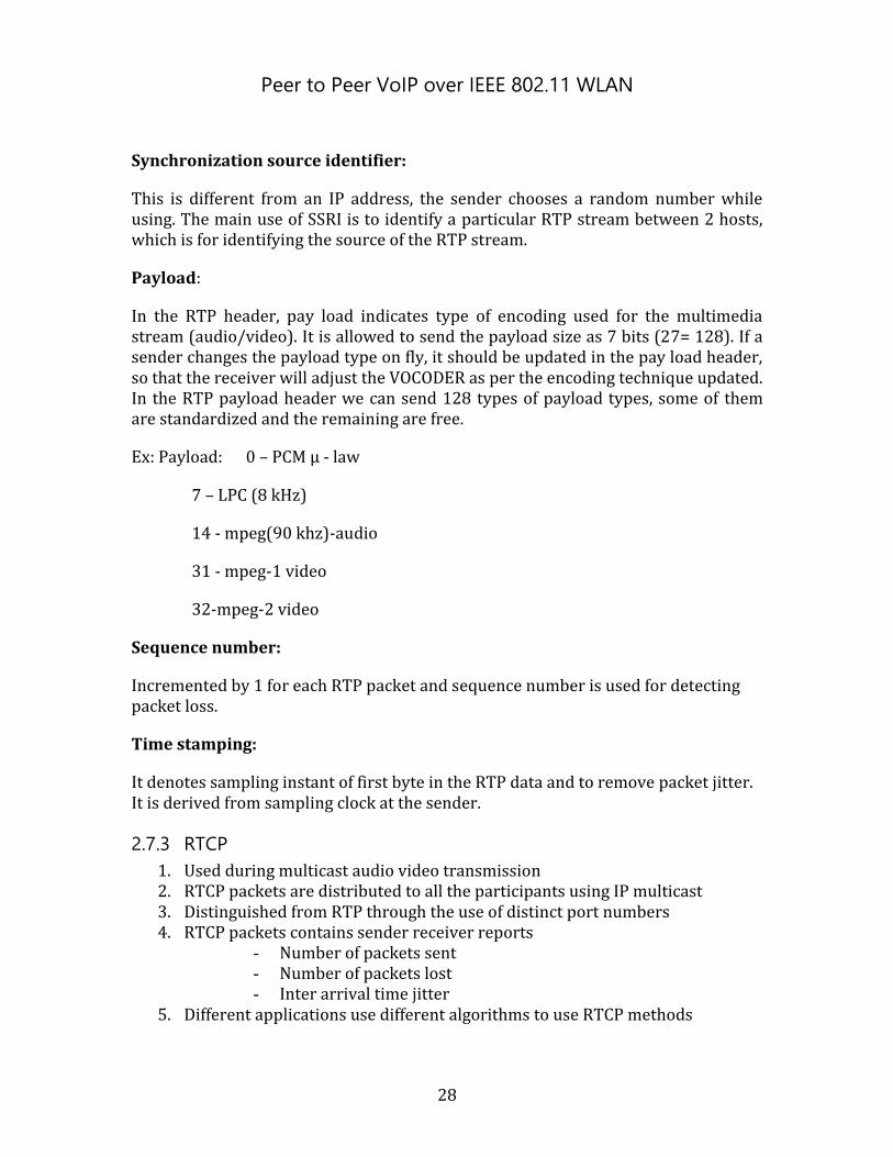
Figure 3.1 : Connecting to an Access-point ........................................................................................................................ 32
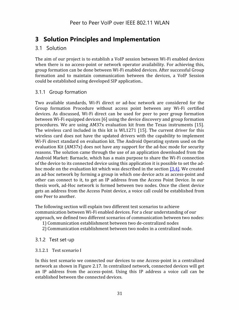
Figure 3.2 : Group formation between devices ................................................................................................................. 32
Figure 3.3 : Getting hardware ready for experiment (Tree view) ............................................................................. 33
Figure 3.4: AM/AM 37 EVM Kit ............................................................................................................................................... 34
Figure 3.5 : Connecting to Access point ............................................................................................................................... 36
Figure 3.6 : Test scenario-1 ...................................................................................................................................................... 37
Figure 3.7 : Test scenario – II .................................................................................................................................................. 38

XII
Figure 3.8 : Group formation between two laptops ........................................................................................................ 38
Figure 3.9 : Access point mode ................................................................................................................................................ 39
Figure 3.10 : Connecting to ad-hoc network...................................................................................................................... 40
Figure 3.11 : Flow chat for Connecting to ad-hoc AP ..................................................................................................... 41
Figure 3.12 : Overview of project ........................................................................................................................................... 43
Figure 4.1 : Test scenario-I ....................................................................................................................................................... 44
Figure 4.2 : Test scenario-II ...................................................................................................................................................... 44
Figure 4.3: Energy consumption measurements for the test scenario I .................................................................. 47
Figure 4.4: Energy consumption measurements for the test scenario II ................................................................ 47
Figure 4.5 : Current measurements ....................................................................................................................................... 48
Figure 4.6 : Application processor Utilization .................................................................................................................. 49
Figure 6.1: Main activity to choose either Ad-Hoc mode or Infrastructure mode .............................................. 55
Figure 6.2 : Ad-hoc activity to setup device in ad-hoc mode ....................................................................................... 55
Figure 6.3: Device running in ad-hoc mode ....................................................................................................................... 56
Figure 6.4: Connected clients are shown using Clients tab activity .......................................................................... 56
Figure 6.5 : Call activity by selecting specific client ........................................................................................................ 57
Figure 6.6 : Signaling between user agents using SIP protocol ................................................................................. 57
Figure 6.7 : Session establishment between user agents .............................................................................................. 58
Figure 6.8 : Device can able to detect ad-hoc networks in scan mode .................................................................... 58
Figure 6.9 : Associating with an ad-hoc device shown by toast view ....................................................................... 59
Figure 6.10: Successful group formation between two devices and call initiation window using toast view .................................................................................................................................................................................................... 59
Figure 6.11 : Call initiation from client side ....................................................................................................................... 60
Figure 6.12 : Session establishment between user agents ............................................................................................ 60
Figure 6.13 : Settings Activity .................................................................................................................................................. 61
Figure 6.14: SIP Settings activity............................................................................................................................................ 61
Figure 6.15 : Wi-Fi Settings activity ...................................................................................................................................... 62
XIII
Tables
Table 2.1: IEEE 802.11 standard protocols ........................................................................................................................ 14
Table 2.2 : Differences between PSTN and VoIP ............................................................................................................... 18
Table 4.1 : Mean Opinion Score test ...................................................................................................................................... 45
Table 4.2 : Audio quality test for Test Scenario I ............................................................................................................. 45
Table 4.3 : Audio quality test for Test scenario II ............................................................................................................ 46
Table 4.4: Current Measurements .......................................................................................................................................... 48
Peer to Peer VoIP over IEEE 802.11 WLAN
1
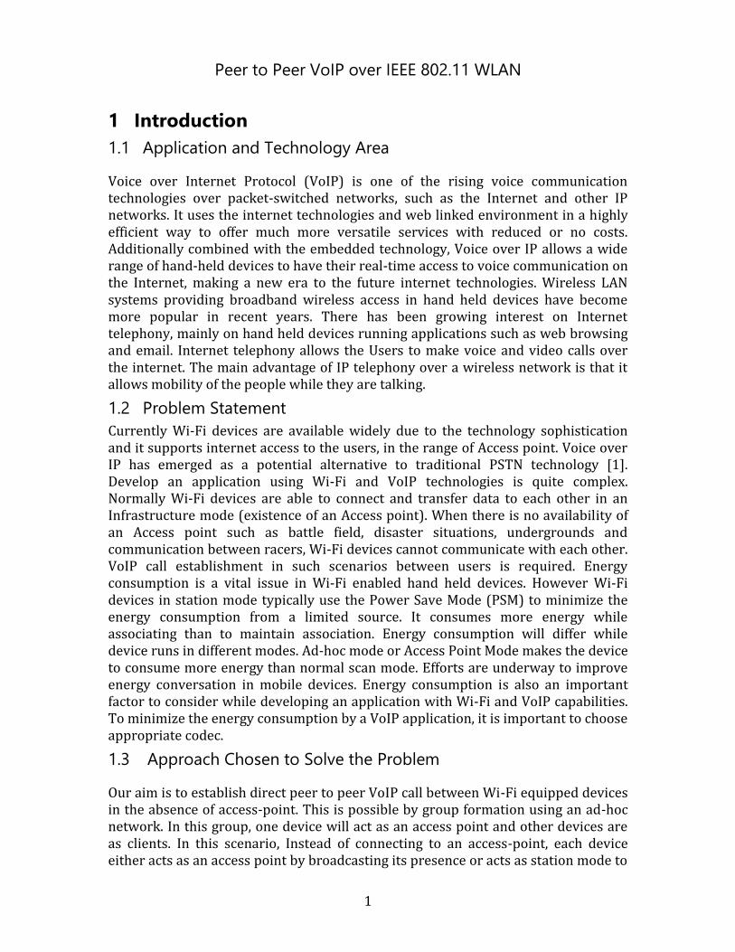
1 Introduction
1.1 Application and Technology Area
Voice over Internet Protocol (VoIP) is one of the rising voice communication technologies over packet-switched networks, such as the Internet and other IP networks. It uses the internet technologies and web linked environment in a highly efficient way to offer much more versatile services with reduced or no costs. Additionally combined with the embedded technology, Voice over IP allows a wide range of hand-held devices to have their real-time access to voice communication on the Internet, making a new era to the future internet technologies. Wireless LAN systems providing broadband wireless access in hand held devices have become more popular in recent years. There has been growing interest on Internet telephony, mainly on hand held devices running applications such as web browsing and email. Internet telephony allows the Users to make voice and video calls over the internet. The main advantage of IP telephony over a wireless network is that it allows mobility of the people while they are talking.
1.2 Problem Statement
Currently Wi-Fi devices are available widely due to the technology sophistication and it supports internet access to the users, in the range of Access point. Voice over IP has emerged as a potential alternative to traditional PSTN technology [1]. Develop an application using Wi-Fi and VoIP technologies is quite complex. Normally Wi-Fi devices are able to connect and transfer data to each other in an Infrastructure mode (existence of an Access point). When there is no availability of an Access point such as battle field, disaster situations, undergrounds and communication between racers, Wi-Fi devices cannot communicate with each other. VoIP call establishment in such scenarios between users is required. Energy consumption is a vital issue in Wi-Fi enabled hand held devices. However Wi-Fi devices in station mode typically use the Power Save Mode (PSM) to minimize the energy consumption from a limited source. It consumes more energy while associating than to maintain association. Energy consumption will differ while device runs in different modes. Ad-hoc mode or Access Point Mode makes the device to consume more energy than normal scan mode. Efforts are underway to improve energy conversation in mobile devices. Energy consumption is also an important factor to consider while developing an application with Wi-Fi and VoIP capabilities. To minimize the energy consumption by a VoIP application, it is important to choose appropriate codec.
1.3 Approach Chosen to Solve the Problem
Our aim is to establish direct peer to peer VoIP call between Wi-Fi equipped devices in the absence of access-point. This is possible by group formation using an ad-hoc network. In this group, one device will act as an access point and other devices are as clients. In this scenario, Instead of connecting to an access-point, each device either acts as an access point by broadcasting its presence or acts as station mode to
Peer to Peer VoIP over IEEE 802.11 WLAN
2
scan other Wi-Fi devices within its range. After group formation between devices, a SIP session needs to be established in order to maintain the communication. Our thesis work is to connect multiple hand held devices within Wi-Fi range so as to make direct IP to IP call between the devices. The device with access point functionality will assign IP addresses to the connected devices dynamically by maintaining DHCP server. In packet switched networks such as VoIP brings the new challenges for the delivery of the real time traffic. Energy consumption is an important factor to consider while developing the application for hand held devices with limited energy source. Our task is based on mobile devices that make us to consider the effect of Wi-Fi and audio codecs on energy consumption. Generally energy consumption will be more when device runs in Access Point Mode. We need to measure and compare energy consumption characteristics in both Access point Mode and Scan Mode. Audio codecs are also show an impact on battery dependent devices during VoIP session. Study of the different codec quality and energy consumption during VoIP session in two test scenarios will give a better approach to increase quality of the application for further development.
1.4 Thesis Goals and Expected Results
1. Group formation between Wi-Fi equipped devices without using Access-point.
2. Establishing a voice call between connected devices in group.
3. Study of the different codec quality during VoIP session in test scenarios I & II
4. Energy consumption measurements of test scenario-I and test scenario-II.
Peer to Peer VoIP over IEEE 802.11 WLAN
3
2 Background
There has been growing interest in VoIP over WLAN. It enables User mobility whilst speaking and Internet access. To make a VoIP call between two Wi-Fi equipped devices, they should have an access to the internet, though they are in the same Wi-Fi range. If two devices are in the same Wi-Fi range, peer to peer voice call can be established without using the internet. Group formation can be done between the devices which are in the same Wi-Fi range. In this project we are going to establish a peer to peer VoIP session by forming a group between devices. First we studied wireless networks, VoIP over WLAN and a new upcoming technology, Wi-Fi direct.
2.1 Wireless Networks
Wireless broadband access to the Internet has recently witnessed excellent growth. Much of this growth has come from the rise of wireless local area networks (WLANs).Wireless LAN network Technologies, commonly in the form of Wi-Fi (802.11) systems, have a huge market growth and penetration in public and private environments, with high speed internet access at numerous locations. Due to high cost, low transmission rate, occupational safety concerns and licensing requirements, this technology was not popular in the past. WLANs today are being widely used in markets such as education, healthcare, manufacturing, retail, hospitality, government and transportation, due to convenience, availability, mobility, reduced cost of ownership and installation flexibility, that making sudden growth in deployment as well as manufacturing of WLAN hardware. At present there are some organizations like FCC, IEEE, the Wi-Fi Alliance and WLANA which are trying to increase the growth of the WLAN technology. WLAN provides mobility to the Users so that we can roam around within the coverage range of WLAN and also it gives fast and less expensive connectivity, without cabling, for reliable data exchange between Users. WLAN used to extend the network by reducing the cost of additional cabling. To connect more than two buildings we can use WLAN technology to make access common network among those Users. Historically, first generation of Wireless modems developed by the amateur groups to an existing short distance radio system such as walkie-talkie. The second generation wireless modems developed for non- military use of the spread spectrum technology. The third generation of wireless modem aimed at compatibility with the present LANs with the data rate on the order of Mbit/s. Home Users and small offices are using Wireless LAN, which gives ease and speed of deployment that makes simple and effective interconnection. Using WLAN, we can create ad-hoc networks (IBSS or Peer to Peer network) for temporary needs, like file sharing and network for the duration of a meeting between a group of people, each with a laptop or hand held devices
Peer to Peer VoIP over IEEE 802.11 WLAN
4
Limitations and challenges: - A wireless LAN cannot be replaced by Wired LAN if we consider data rates
and error rates. - Due to the susceptibility of radio transmissions to noise and interference, the
reliability of data transmission is comparatively less than Wired LAN. - Strength of the transmitted signal will fluctuate in various paths, which
causes fading - Security problems arises due to the possibility of eavesdropping - Spread spectrum techniques also affect the data rates that enforce into the
industrial, scientific and medical (ISM) band users.
2.2 Wireless Ad-Hoc Networks
Wireless networks are being widely used in the field of communication among the wide variety of devices in different sizes, such as personal computers, handhelds, telephones, appliances, industrial machines, sensor devices. These are being used in public and private environments. “A wireless ad hoc network is a collection of wireless nodes that can dynamically self-organize into an arbitrary and temporary topology, to form a network without necessarily using any pre-existing infrastructure” [2]. These characteristics make ad hoc networks well suited for military activities, emergency operations, and disaster recoveries. Nevertheless, as electronic devices are getting smaller, cheaper, and more powerful, the mobile market is rapidly growing and, as a consequence, the need of seamlessly internetworking people and devices becomes mandatory. New wireless technologies enable easy deployment of commercial applications for ad hoc networks. The design of an ad hoc network has to take into account several interesting and difficult problems due to noisy, limited-range and insecure wireless transmissions, added to mobility and energy constraints.
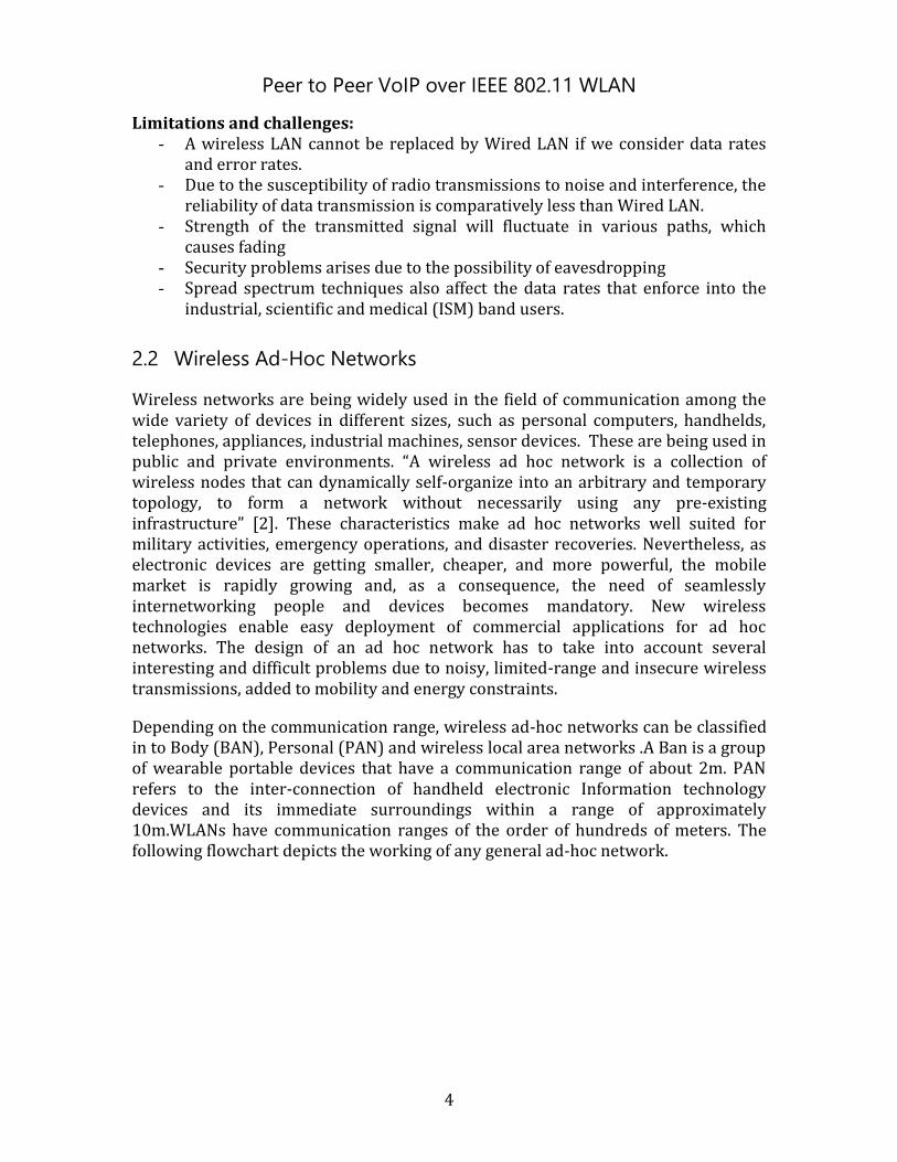
Depending on the communication range, wireless ad-hoc networks can be classified in to Body (BAN), Personal (PAN) and wireless local area networks .A Ban is a group of wearable portable devices that have a communication range of about 2m. PAN refers to the inter-connection of handheld electronic Information technology devices and its immediate surroundings within a range of approximately 10m.WLANs have communication ranges of the order of hundreds of meters. The following flowchart depicts the working of any general ad-hoc network.
Peer to Peer VoIP over IEEE 802.11 WLAN
5
Figure 2.1: ad-hoc network formation
User agents in ad-hoc networks can function not only as end systems such as performing tasks, transforming the information from the sender as source nodes and receiving at the other end as receiver nodes. The dual functionality of the User agents in the network leads to have a chance of communication between two nodes even though they are outside of each other’s transmission ranges by allowing intermediate nodes functioning as routers. If one of the intermediate nodes were to fail (e.g. that User leaves the area), the network will automatically reconfigure itself locating an alternate path from the User to the router. Typically, all available nodes are also network Users, each sharing the total data transfer capacity of the particular hardware and operating protocol being used. The need of self-configurability and adjusting at various levels imposes new challenges in wireless ad-hoc networks.
The design of a Wireless ad hoc network must be considered to solve several interesting and difficult problems, when we are comparing to the traditional wireless communication systems. The problems related to the physical medium, such as low transmission, high bit error rates, limited range and, noise factor must be taken into account to solve them. In the Mac Layer the difficulty of collision detection and problems with the hidden and exposed terminal requires new medium access algorithms .In ad-hoc networking, the wireless accessory nodes may move to a temporary position and the status of the communication links between the ad-Hoc nodes may vary. Conventional Routing protocols used for the wired networks may not suit for the wireless ad-hoc networking. A number of Routing protocols have been proposed to co-operate with the various challenges of ad-hoc
Peer to Peer VoIP over IEEE 802.11 WLAN
6
networks also demanding transport layer protocols to overcome high bit-error rates and frequent route failures.
Basically there are two types of routing protocols: 1. Proactive Routing Protocols: Here in the nodes keep updating their routing tables by
periodical messages. This can be seen in Optimized Link State Routing Protocol (OLSR) and the Topology Broadcast based on Reverse Path Forwarding Protocol (TBRPF).
2. Reactive or On Demand Routing Protocols: Here the routes are created only when they are needed. The application of this protocol can be seen in the Dynamic Source Routing Protocol (DSR) and the ad-hoc On-demand Distance Vector Routing Protocol (AODV).
Currently, the most common ad-hoc protocols are the ad-hoc On-demand Distance Vector routing protocol, Destination-Sequenced Distance-Vector routing protocol and Dynamic Source Routing. All these protocols are quite insecure because attackers can easily obtain information about the network topology. This is because in the AODV and DSR protocols, the route discovery packets are carried in clear text. Thus a malicious node can discover the network structure just by analysing this kind of packets and may be able to determine the role of each node in the network. Using all this information, more serious attacks can be launched in order to disrupt network operations.
2.3 Wi-Fi Direct
In general, Wi-Fi allows the deployment of local area networks for client devices, where cables cannot be run, such as outdoor areas and historical buildings, which can host wireless LAN; this typically reduces the costs of network management and expansion. Normally Wi-Fi networks are set up in infrastructure mode, where the access point acts as a central hub. Wi-Fi has always claimed to support a second mode, "ad-hoc mode", where networking is automatically provided between Wi-Fi enabled devices, using ad-hoc mode, two Wi-Fi devices can theoretically set up a connection between them entirely automatically.
Wi-Fi Direct is an upcoming program from the Wi-Fi Alliance that defines a new way for Wi-Fi devices to work together, to meet the increasing demand for easy, portable wireless network connectivity. Wi-Fi direct is a P2P wireless networking, allowing devices like notebooks, tablets, cameras, and printers to "find" each other and establish wireless connectivity in the absence of an access point, or a hotspot.
Wi-Fi Direct is a set of software protocols that allow Wi-Fi devices to talk and connect to each other without prior setup or the need for joining a traditional wireless access points. [6] A Wi-Fi Direct network can be one-to-one, or one-to-many. The number of devices in a Wi-Fi Direct network is expected to be smaller than the number supported by the traditional infrastructure mode. All Wi-Fi Direct devices will allow the User to connect to an infrastructure or a Wi-Fi Direct network. Some Wi-Fi Direct devices will support connections to both an infrastructure network and Wi-Fi Direct network at the same time. Wi-Fi Direct is developed
Peer to Peer VoIP over IEEE 802.11 WLAN
7
within the Wi-Fi Alliance by member companies and Legacy Wi-Fi devices are supported, as it operates on 802.11 devices (b/g/n) but is not linked to any specific IEEE 802.11 alternation. [9]
Figure 2.2 Wi-Fi direct [10]
2.3.1 Wi-Fi Direct and existing Wi-Fi standards
A Wi-Fi Direct device will be able to make device-to-device connections with existing IEEE 802.11 a/b/g/n standards. The peer to peer networks always allows devices to exchange data with each other without an access point, but implementations affects poor security and degraded throughput. Wi-Fi Direct is a substitution of the affected ad-hoc networking mode as a part of 802.11. The best advantage of the new method is that it can preserve the full bandwidth of 802.11 and overtakes incompatibility issues that ad-hoc would suffer. The most significant difference between traditional Peer-to-Peer networking and Wi-Fi Direct is security. Wi-Fi Direct connections will work, at typical Wi-Fi ranges, protected by WPA security protocols and including WMM QoS mechanisms. It supports WPS and WPA2 by default. The new specification places a premium on security; it was developed to have separate security domains, so your WLAN connection is a separate security domain from your Wi-Fi Direct network. Another difference, Wi-Fi Direct devices can also simultaneously connect to existing wireless networks [7]. More granular control and better discovery of devices also differentiate Wi-Fi Direct from ad-hoc networking. Wi-Fi Direct adds up technology known as “Soft Access Point”, in a few words, it is a software-based access point functionality built into Wi-Fi Direct certified devices [10]. These devices are capable of routing and directing network traffic just like access points and routers. Wi-Fi Direct devices may not provide the overall range of a wireless router or AP. There is more flexibility with Access Points and routers, as they can be placed strategically to provide optimized signal strength. Also, there are security considerations with Wi-Fi Direct; there is a good chance that IT departments with corporate wireless networks may have issues with controlling Wi-Fi Direct devices.
Peer to Peer VoIP over IEEE 802.11 WLAN
8
2.3.2 Architectural overview
In the Wi-Fi direct network architecture, device to device interaction can be done by using Wi-Fi direct enabled devices (P2P device). The P2P device is a Wi-Fi Alliance P2P certified device that is capable of acting as both a P2P Group Owner and a P2P Client supports Wi-Fi simple configuration [8] and P2P discovery mechanism and also may support concurrent operation by working with WLAN and P2P at the same time by using dual mac layer support [10].These certified devices can act as
P2P group owner: It acts as an AP (access point) that offers Basic Service Set functionality with WSC internal registry functionality. It provides communication between associated clients including legacy clients and sometimes it may provide simultaneous W LAN connection between associated clients and P2P Group Owner transmits Beacon frames using OFDM (orthogonal frequency division multiplexing)
P2P Client role: It functions as non-access point device role and it offers WSC enroller functionality.
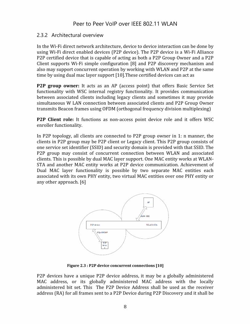
In P2P topology, all clients are connected to P2P group owner in 1: n manner, the clients in P2P group may be P2P client or Legacy client. This P2P group consists of one service set identifier (SSID) and security domain is provided with that SSID. The P2P group may consist of concurrent connection between WLAN and associated clients. This is possible by dual MAC layer support. One MAC entity works at WLAN-STA and another MAC entity works at P2P device communication. Achievement of Dual MAC layer functionality is possible by two separate MAC entities each associated with its own PHY entity, two virtual MAC entities over one PHY entity or any other approach. [6]
Figure 2.3 : P2P device concurrent connections [10]
P2P devices have a unique P2P device address, it may be a globally administered MAC address, or its globally administered MAC address with the locally administered bit set. This The P2P Device Address shall be used as the receiver address (RA) for all frames sent to a P2P Device during P2P Discovery and it shall be
Peer to Peer VoIP over IEEE 802.11 WLAN
9
used as the transmitter address (TA) for all frames sent by a P2P Device during P2P Discovery. The P2P device will act as group owner or client role when it is in a P2P group. The P2P device will assign an interface addressing mechanism, which is used to communicate with P2P group owner or clients within the P2P group. The Interface address may be as same as the device address, provided the requirements for the P2P interface address in this clause are satisfied.
2.4 IEEE802.11 Architecture
The Most wireless networks are based on IEEE 802.11 standards. Basic wireless network consist of set of service stations, communicating each other using radio signals which broadcast in either the 2.4GHz or 5GHz band. Neighbouring channels are 5 MHz apart. IEEE 802.11 standards services include managing associations, delivering data and security. There are mainly three parameters that characterize Wired and Wireless LAN’s. Those are transmission media, topology and medium access control techniques.
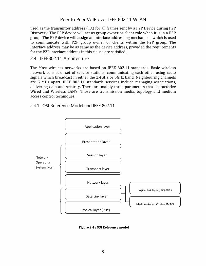
2.4.1 OSI Reference Model and IEEE 802.11
Figure 2.4 : OSI Reference model
Application layer
Presentation layer
Session layer
Transport layer
Network layer
Data Link layer
Physical layer (PHY)
Logical link layer (LLC) 802.2
Medium Access Control (MAC)
Network
Operating
System (NOS)
802.11
Peer to Peer VoIP over IEEE 802.11 WLAN
10
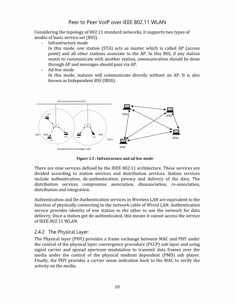
Considering the topology of 802.11 standard networks, it supports two types of modes of basic service set (BSS).
- Infrastructure mode In this mode, one station (STA) acts as master which is called AP (access point) and all other stations associate to the AP. In this BSS, if any station wants to communicate with another station, communication should be done through AP and messages should pass via AP.
- Ad-hoc mode In this mode, stations will communicate directly without an AP. It is also known as Independent BSS (IBSS).
Figure 2.5 : Infrastructure and ad-hoc mode
There are nine services defined by the IEEE 802.11 architecture. These services are divided according to station services and distribution services. Station services include authentication, de-authentication, privacy and delivery of the data. The distribution services compromise association, disassociation, re-association, distribution and integration.
Authentication and De-Authentication services in Wireless LAN are equivalent to the function of physically connecting to the network cable of Wired LAN. Authentication service provides identity of one station to the other to use the network for data delivery. Once a station got de-authenticated, this means it cannot access the service of IEEE 802.11 WLAN.
2.4.2 The Physical Layer:
The Physical layer (PHY) provides a frame exchange between MAC and PHY under the control of the physical layer convergence procedure (PLCP) sub layer and using signal carrier and spread spectrum modulation to transmit data frames over the media under the control of the physical medium dependent (PMD) sub player. Finally, the PHY provides a carrier sense indication back to the MAC to verify the activity on the media.
Peer to Peer VoIP over IEEE 802.11 WLAN
11
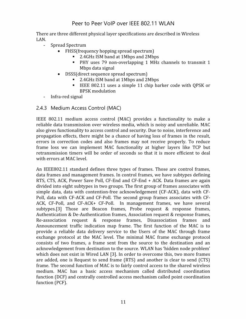
There are three different physical layer specifications are described in Wireless LAN.
- Spread Spectrum FHSS(frequency hopping spread spectrum)
2.4GHz ISM band at 1Mbps and 2Mbps PHY uses 79 non-overlapping 1 MHz channels to transmit 1
Mbps data signal DSSS(direct sequence spread spectrum)
2.4GHz ISM band at 1Mbps and 2Mbps IEEE 802.11 uses a simple 11 chip barker code with QPSK or
BPSK modulation - Infra-red signal
2.4.3 Medium Access Control (MAC)
IEEE 802.11 medium access control (MAC) provides a functionality to make a reliable data transmission over wireless media, which is noisy and unreliable. MAC also gives functionality to access control and security. Due to noise, interference and propagation effects, there might be a chance of having loss of frames in the result, errors in correction codes and also frames may not receive properly. To reduce frame loss we can implement MAC functionality at higher layers like TCP but retransmission timers will be order of seconds so that it is more efficient to deal with errors at MAC level.
An IEEE802.11 standard defines three types of frames. Those are control frames, data frames and management frames. In control frames, we have subtypes defining RTS, CTS, ACK, Power Save Poll, CF-End and CF-End + ACK. Data frames are again divided into eight subtypes in two groups. The first group of frames associates with simple data, data with contention-free acknowledgement (CF-ACK), data with CF-Poll, data with CF-ACK and CF-Poll. The second group frames associates with CF-ACK, CF-Poll, and CF-ACK+ CF-Poll. In management frames, we have several subtypes.[3] Those are Beacon frames, Probe request & response frames, Authentication & De-Authentication frames, Association request & response frames, Re-association request & response frames, Disassociation frames and Announcement traffic indication map frame. The first function of the MAC is to provide a reliable data delivery service to the Users of the MAC through frame exchange protocol at the MAC level. The minimal MAC frame exchange protocol consists of two frames, a frame sent from the source to the destination and an acknowledgement from destination to the source. WLAN has ‘hidden node problem’ which does not exist in Wired LAN [3]. In order to overcome this, two more frames are added, one is Request to send frame (RTS) and another is clear to send (CTS) frame. The second function of MAC is to fairly control access to the shared wireless medium. MAC has a basic access mechanism called distributed coordination function (DCF) and centrally controlled access mechanism called point coordination function (PCF).
Peer to Peer VoIP over IEEE 802.11 WLAN
12
In basic access mechanism, carrier sense multiple access with collision avoidance (CSMA/CA) is used, which is based on the ‘listen before talk’ mechanism. The Station starts using medium for own transmission after checking channel is idle (no other Node is using the channel at that moment) on regular timing intervals. There are two basic intervals defined by PHY, short inter frame space (SIFS) and slot time. [3] Three additional intervals are defined on basic intervals priority inter frame space (PIFS), distributed inter frame space (DIFS) and extended inter frame space (EIPS). Based on these five intervals, DCF and PCF are implemented. In DCF, whenever MAC receives a request to send a frame, it will check the medium by physical and virtual carrier sense mechanism. If the medium is free for an interval of DIFS, MAC will start transmission otherwise it uses back-off interval using binary exponential back-off mechanism until back-off interval expires. PCF (centrally controlled access mechanism) uses polls and response protocol to eliminate the medium contention. It is always located in AP.
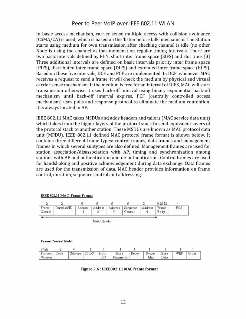
IEEE 802.11 MAC takes MSDUs and adds headers and tailors (MAC service data unit) which takes from the higher layers of the protocol stack to send equivalent layers of the protocol stack to another station. These MSDUs are known as MAC protocol data unit (MPDU). IEEE 802.11 defined MAC protocol frame format is shown below. It contains three different frame types: control frames, data frames and management frames in which several subtypes are also defined. Management frames are used for station association/disassociation with AP, timing and synchronization among stations with AP and authentication and de-authentication. Control frames are used for handshaking and positive acknowledgement during data exchange. Data frames are used for the transmission of data. MAC header provides information on frame control, duration, sequence control and addressing.
Figure 2.6 : IEEE802.11 MAC frame format
Peer to Peer VoIP over IEEE 802.11 WLAN
13
2.4.4 Management
IEEE 802.11 WLAN must deal with some challenges like intermittent connection, eavesdropping, mobility and power management. To overcome all these challenges, IEEE 802.11 standard defines tools: authentication, association, address filtering, power management, privacy, and synchronization. The Authentication mechanism comprises of one station to prove its identity to another station in the WLAN. The steps involved in the authentication process are exchange of questions, assertions and results. There are two algorithms defined in IEEE 802.11 standard. One is open system authentication and the second one is shared key authentication.
Association is the process of a mobile station connecting to an AP and requesting service from the WLAN. Because IEEE802.11 is the alternative solution to the wired connection, so stations will move within the range and all stations should maintain connection with AP.
Power management is the most complex part in IEEE802.11. In this mechanism, mobile stations will be in power saving mode, in which stations will turn off their transmitter and receiver. There are different mechanisms for Infrastructure Mode and ad-hoc Mode. In ad-hoc Mode or independent BSS (IBSS) power management will be distributed among mobile stations. A station must successfully complete a data frame handshake with another station with the power management bit set in the frame header before it goes to low power operating mode. So until completion of the handshake, the station must remain in the wake state. The station must wake up to receive the beacon transmission and it should awake for a period of time after each beacon, which is known as announcement or ad-hoc traffic indication message window (ATIM). The Sending station should get an acknowledgement of an ATIM window from the destination before it transmits the data frame to the destination. The Burden will be more on the sending station than on the receiving station, with the power management mechanism. However, there is a minimum duty cycle required of both senders and destinations, in the ratio of the time of the ATIM window to the time of the beacon period.
Timing synchronization is distributed among mobile stations in IBSS due to absence of AP. Whichever station starts the basic beaconing process, i.e. a station which starts BSS will begin by resetting TSF (timer synchronization function) to zero and transmits a beacon with beacon period. After receiving TBTT (target beacon transmission time) each station in IBSS starts sending beacon frames. At least one beacon frame should send in one beacon period and to avoid collision of beacon frames, each station will choose random delay values. If a station receives beacon from another station before the delay expires, the received station will stop the beacon transmission. Beaconing also plays a major role in power management in IBSS. There should be at least one station in the IBSS awake and able to respond to probe request frames. In IBSS, a station will update TSF timer with the value of a received beacon frame. IEEE 802.11 developed MAC level privacy mechanisms to protect the content of data frames from unwanted monitoring and eavesdropping
Peer to Peer VoIP over IEEE 802.11 WLAN
14
due to medium difference between Wired and Wireless LAN’s. To overcome security and privacy issues in Wireless LAN, IEEE 802.11 defines an optimal MAC layer security system known as wired equivalent privacy (WEP). This can be done with fixed shared key authentication service. Another privacy protocol specification used in wireless LAN is Wireless protected access (WPA).
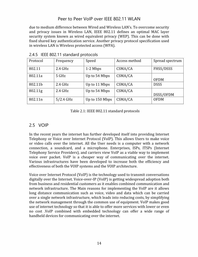
2.4.5 IEEE 802.11 standard protocols
Protocol Frequency Speed Access method Spread spectrum
802.11 2.4 GHz 1-2 Mbps CSMA/CA FHSS/DSSS
802.11a 5 GHz Up to 54 Mbps CSMA/CA OFDM
802.11b 2.4 GHz Up to 11 Mbps CSMA/CA DSSS
802.11g 2.4 GHz Up to 54 Mbps CSMA/CA DSSS/OFDM
802.11n 5/2.4 GHz Up to 150 Mbps CSMA/CA OFDM
Table 2.1: IEEE 802.11 standard protocols
2.5 VOIP
In the recent years the internet has further developed itself into providing Internet Telephony or Voice over Internet Protocol (VoIP). This allows Users to make voice or video calls over the internet. All the User needs is a computer with a network connection, a soundcard, and a microphone. Enterprises, ISPs, ITSPs (Internet Telephony Service Providers), and carriers view VoIP as a viable way to implement voice over packet. VoIP is a cheaper way of communicating over the internet. Various infrastructures have been developed to increase both the efficiency and effectiveness of both the VOIP systems and the VOIP architecture.
Voice over Internet Protocol (VoIP) is the technology used to transmit conversations digitally over the Internet. Voice-over-IP (VoIP) is getting widespread adoption both from business and residential customers as it enables combined communication and network infrastructure. The Main reasons for implementing the VoIP are it allows long distance communication such as voice, video and data which can be carried over a single network infrastructure, which leads into reducing costs, by simplifying the network management through the common use of equipment. VoIP makes good use of internet technology so that it is able to offer more services with lower or even no cost .VoIP combined with embedded technology can offer a wide range of handheld devices for communicating over the internet.
Peer to Peer VoIP over IEEE 802.11 WLAN
15
2.5.1 VoIP Components
The basic steps involved in originating an Internet telephone call are conversion of the analogue voice signal to digital format and compression/translation of the signal into internet protocol packets for transmission over the internet; the process is reversed at the receiving end. Compared to current PSTNs, in order to enable organizations to adopt VoIP as a viable solution, the VoIP components must perform functions such as:
Signaling: Signaling is the way that devices communicate within the network, activating and coordinating the various components needed to complete a call (accomplished by exchange of data grams between end terminals).
Database services: A VoIP network uses an IP address and port number to locate an end point, address abstraction could be accomplished with DNS.
Call bearer control: The connection of a call is made by two endpoints opening a communication session between each other. In a VoIP implementation, connection is a multimedia stream transported in real time. Once communication is complete, the IP sessions are released and optionally network resources are freed.
Codec Operations: The process of converting analogue waveforms to digital information is done with a coder-decoder (VOCODER), the data stream from the VOCODER is put into IP packets and transported across the network to the end terminals. Two end points will use the same ITU encoding standards (ex: G.7 family) and common set of CODEC parameters.
The major components of a VoIP network, while different in approach, deliver very similar functionality to that of a PSTN and enable VoIP networks to perform all of the same tasks that the PSTN does. The one additional requirement is that VoIP networks must contain a gateway component that enables VoIP calls to be sent to a PSTN, and vice - versa. There are four major components to a VoIP network.
- Call Processing Server/IP PBX
- User End-Devices
- Media/VoIP Gateways
- IP network
Peer to Peer VoIP over IEEE 802.11 WLAN
16
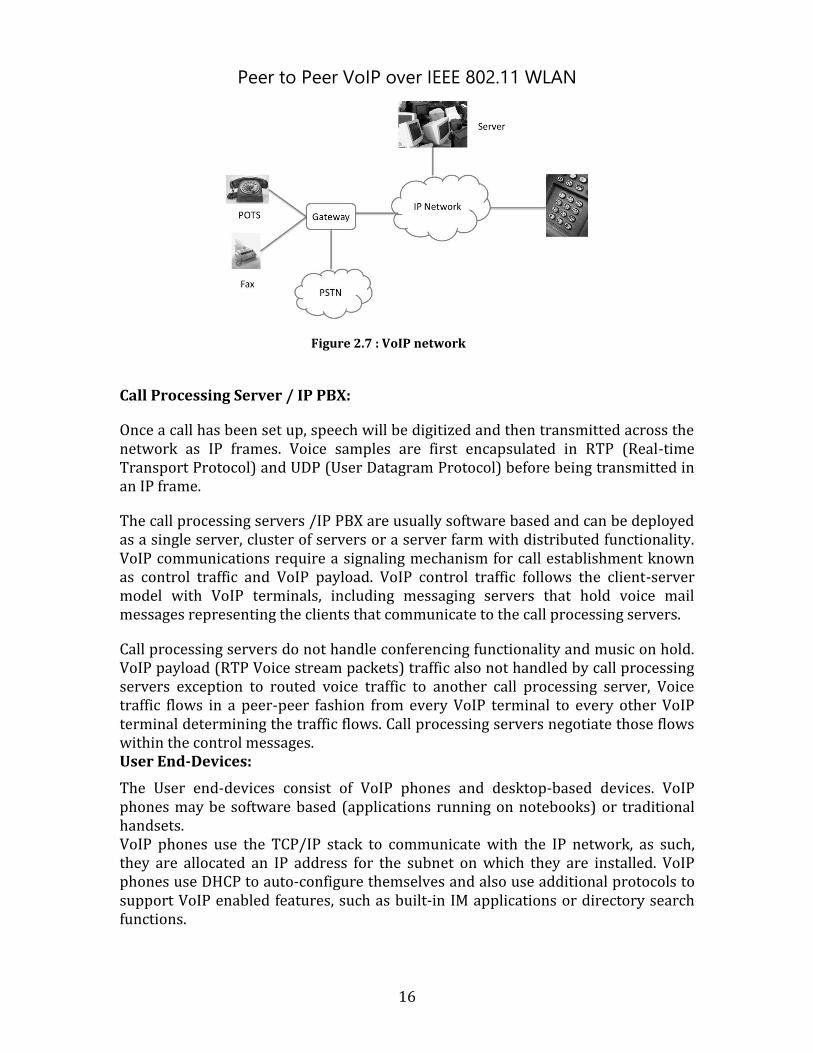
Figure 2.7 : VoIP network
Call Processing Server / IP PBX:
Once a call has been set up, speech will be digitized and then transmitted across the network as IP frames. Voice samples are first encapsulated in RTP (Real-time Transport Protocol) and UDP (User Datagram Protocol) before being transmitted in an IP frame.
The call processing servers /IP PBX are usually software based and can be deployed as a single server, cluster of servers or a server farm with distributed functionality. VoIP communications require a signaling mechanism for call establishment known as control traffic and VoIP payload. VoIP control traffic follows the client-server model with VoIP terminals, including messaging servers that hold voice mail messages representing the clients that communicate to the call processing servers.
Call processing servers do not handle conferencing functionality and music on hold. VoIP payload (RTP Voice stream packets) traffic also not handled by call processing servers exception to routed voice traffic to another call processing server, Voice traffic flows in a peer-peer fashion from every VoIP terminal to every other VoIP terminal determining the traffic flows. Call processing servers negotiate those flows within the control messages. User End-Devices:
The User end-devices consist of VoIP phones and desktop-based devices. VoIP phones may be software based (applications running on notebooks) or traditional handsets. VoIP phones use the TCP/IP stack to communicate with the IP network, as such, they are allocated an IP address for the subnet on which they are installed. VoIP phones use DHCP to auto-configure themselves and also use additional protocols to support VoIP enabled features, such as built-in IM applications or directory search functions.
Peer to Peer VoIP over IEEE 802.11 WLAN
17
VoIP Gateways:
Gateways are mainly used for call admission, control and bandwidth management. The major function of media gateways is analogue to digital conversion of voice and creation of voice IP packets (CODEC functions), in addition, media gateways have optional features such as voice compression, echo cancellation, silence suppression and statistics gathering. The media gateway forms the interface that the voice content uses so it can be transported over the IP network. Media gateways are the sources of bearer traffic. Typically, each conversation (call) is a single IP session transported by a Real-time Transport Protocol (RTP) that runs over UDP or TCP.
Media gateways exist in several forms. Their features and services can include some or all of the following:
- Trunking gateways that interface between the telephone network and a VoIP network. Such gateways typically manage a large number of digital circuits. - Residential gateways that provide a traditional analog interface to a VoIP network. Examples of residential gateways include cable modem/cable set-top boxes, xDSL devices and broadband wireless devices.
- Access media gateways that provide a traditional analog or digital PBX interface to a VoIP network. Examples include small-scale (enterprise) VoIP gateways.
- Business media gateways that provide a traditional digital PBX interface or an integrated soft PBX interface to a VoIP network.
- Network access servers that can attach a modem to a telephone circuit and provide data access to the Internet.
Gateway communication should be secured with internet protocol Security (IPSec) to prevent interference with calls and to prevent unauthorized calls from being set up. The gateway itself is vulnerable to internet protocol based attacks and can be mitigated by using internet protocol Security (IPSec) and by removing any unnecessary services and open ports, as should be done with any server.
2.5.2 Difference between PSTN and VoIP
In the Public Switched Telephone Network (PSTN), the system works by setting up a dedicated channel established between two points for duration of the call. These telephony systems are based on copper wires carrying analogue voice data over the dedicated circuits known as circuit switching networks.
Compared to newer Internet telephony networks based on digital technologies, VoIP uses packet-switched telephony. Using this system, the voice information travels to its destination in countless individual network packets across the Internet. Individual packets may and almost always take different paths to the same place. It is not enough to simply get VoIP packets to their destination. They must arrive through a fairly narrow time window and be assembled in the correct order to be intelligible to the recipient. VoIP employs encoding schemes and compression
Peer to Peer VoIP over IEEE 802.11 WLAN
18
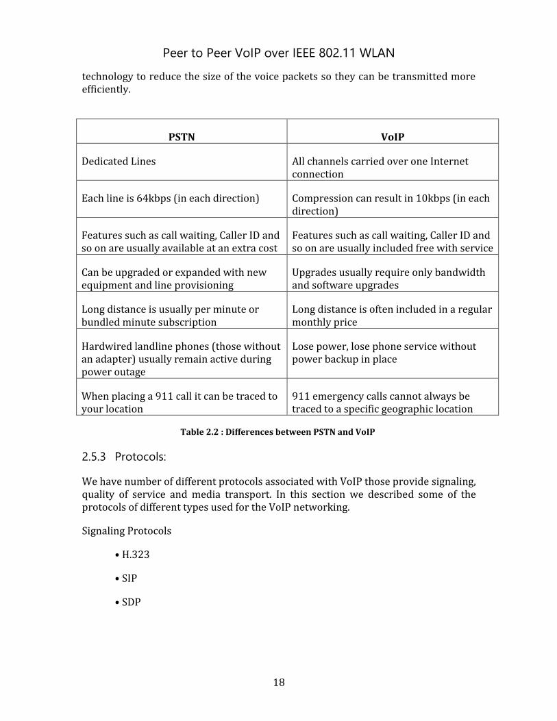
technology to reduce the size of the voice packets so they can be transmitted more efficiently.
PSTN VoIP
Dedicated Lines All channels carried over one Internet connection
Each line is 64kbps (in each direction) Compression can result in 10kbps (in each direction)
Features such as call waiting, Caller ID and so on are usually available at an extra cost
Features such as call waiting, Caller ID and so on are usually included free with service
Can be upgraded or expanded with new equipment and line provisioning
Upgrades usually require only bandwidth and software upgrades
Long distance is usually per minute or bundled minute subscription
Long distance is often included in a regular monthly price
Hardwired landline phones (those without an adapter) usually remain active during power outage
Lose power, lose phone service without power backup in place
When placing a 911 call it can be traced to your location
911 emergency calls cannot always be traced to a specific geographic location
Table 2.2 : Differences between PSTN and VoIP
2.5.3 Protocols:
We have number of different protocols associated with VoIP those provide signaling, quality of service and media transport. In this section we described some of the protocols of different types used for the VoIP networking.
Signaling Protocols
• H.323
• SIP
• SDP
Peer to Peer VoIP over IEEE 802.11 WLAN
19
Quality of service Protocols
• RSVP
• RTCP
• RTSP
Media Transport Protocol
• RTP
Assuming VoIP as a standard service, these protocols are at the heart of any IP session.
i) H.323
In a VoIP session H.323 protocol provides the service for call connection, call management, and call termination. It is a signaling protocol recommended by the International Telecommunications Union (ITU). The ITU describes and standardizes its own set of protocols that differ from those of the Internet Engineering Task Force (IETF). H.323 includes H.245 for control, H.225.0 for connection establishment, H.332 for large conferences, H.450.1 H.450.2 and H.450.3 for supplementary services, H.235 for security, and H.246 for interoperability with circuit-switched services
ii) SDP
The SDP (Session Description Protocol) is a signaling protocol that is used to describe multimedia sessions for VoIP. It describes the media streams that are being transmitted including the number and type of each media. SDP also provides is the payload type that can be transmitted, port numbers and initiator information including name and contact number.
iii) RSVP
The Resource Reservation Protocol is not strictly a quality of service protocol. RSVP handles routing and, as the name suggests, reservation of resources. The resources include bandwidth, grade of service, carrier selection and payment selection. The grade of service and bandwidth relate it to being a quality of service protocol. These reservations can take place either before or after the data begins to be transmitted. Due to the complexity of RSVP, because of extensive features, it is becoming redundant. It has been proposed that the services be completed using Real Time Control Protocol (RTCP) messages. An RTCP message can be modified to contain an additional field that would specify the desired grade of service.
Peer to Peer VoIP over IEEE 802.11 WLAN
20
iv) RTSP
The Real Time Streaming Protocol is used to control video and audio media across a network. It gives the User “VCR” like controls over this media, by controlling a stored media server. It instructs the server using these controls what to do with the media. This is useful for voice mail in IP telephony, or recording a video or audio conference so that it can be listened to again in the future.
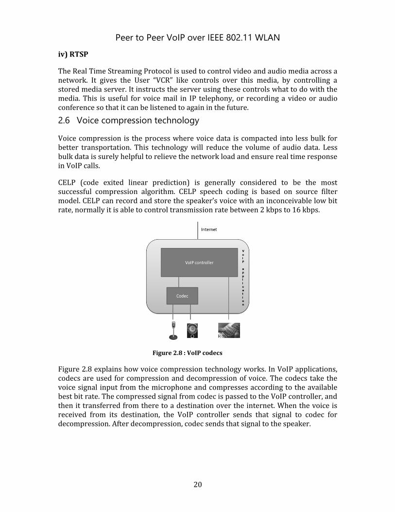
2.6 Voice compression technology
Voice compression is the process where voice data is compacted into less bulk for better transportation. This technology will reduce the volume of audio data. Less bulk data is surely helpful to relieve the network load and ensure real time response in VoIP calls.
CELP (code exited linear prediction) is generally considered to be the most successful compression algorithm. CELP speech coding is based on source filter model. CELP can record and store the speaker’s voice with an inconceivable low bit rate, normally it is able to control transmission rate between 2 kbps to 16 kbps.
Figure 2.8 : VoIP codecs
Figure 2.8 explains how voice compression technology works. In VoIP applications, codecs are used for compression and decompression of voice. The codecs take the voice signal input from the microphone and compresses according to the available best bit rate. The compressed signal from codec is passed to the VoIP controller, and then it transferred from there to a destination over the internet. When the voice is received from its destination, the VoIP controller sends that signal to codec for decompression. After decompression, codec sends that signal to the speaker.
Peer to Peer VoIP over IEEE 802.11 WLAN
21
2.6.1 Speex codec:
Speex is an open source codec, based on the popular Code Exited Linear Prediction (CELP) algorithm with a wide range of bit rate .It is a flexible audio codec for the development of Voice over IP (VoIP) on Linux and other free operating systems. Speex is considered to be optimized for speech and is designed for low latency communication over an unreliable packet switching network [12]. Speex has modest complexity and it is targeted at wide range of devices
Some of the main Speex codec are:
Sampling rate: it is designed for 3 sampling rates referred to as narrowband (8 kHz), wideband (16 kHz), ultra wideband (32 kHz)
Quality: Speex quality parameter ranges from 0to 10.In constant bit (CBR) operation, the quality parameter is an integer while for variable bit-rate, and it is float.
Complexity: Speex allows varying the complexity allowed for the encoder by controlling how the search is performed with the quality parameter.
Variable Bit Rate: It allows audio codec to change its bit rate dynamically to adapt to the hardness of the audio being encoded. Speex codec encodes the high energy transients with high bit rate to achieve good quality while fricatives encoded sufficient with less bits. Regardless of its advantages, there is no guaranty about the final average bit-rate and for the real time applications like VoIP it counts maximum bit-rate without considering the communication channel capacity.
Average bit rate: Average bit-rate solves the problems of VBR. It adjusts VBR quality dynamically in order to meet specific bit rate.
Also includes
- Voice activity detection (VAD, integrated with VBR) and discontinuous transmission (DTX),
- Variable complexity, Ultra-wideband sampling rate 32 kHz,
- Embedded wideband structure(Scalable sampling rate)
- Intensity stereo encoding option, Fixed-point implementation
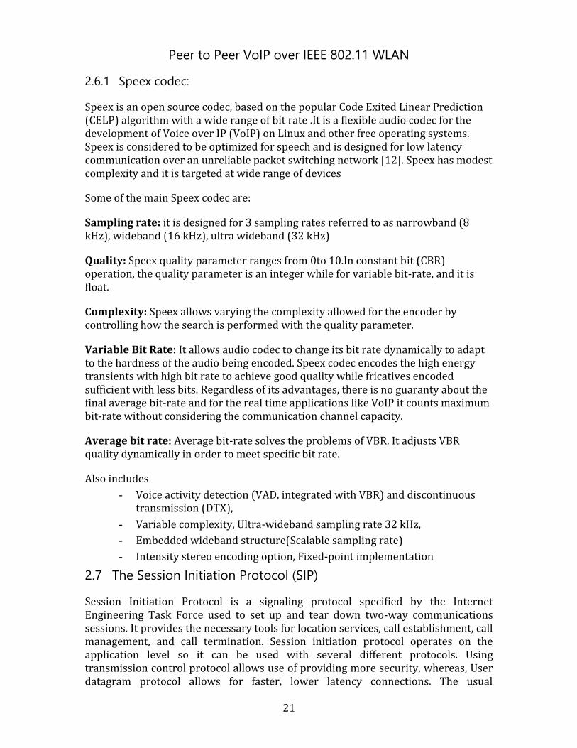
2.7 The Session Initiation Protocol (SIP)
Session Initiation Protocol is a signaling protocol specified by the Internet Engineering Task Force used to set up and tear down two-way communications sessions. It provides the necessary tools for location services, call establishment, call management, and call termination. Session initiation protocol operates on the application level so it can be used with several different protocols. Using transmission control protocol allows use of providing more security, whereas, User datagram protocol allows for faster, lower latency connections. The usual
Peer to Peer VoIP over IEEE 802.11 WLAN
22
components software contains client and server components. The client piece makes outgoing calls and the server is responsible for receiving incoming calls. The proxy server forwards traffic, the registrar server authenticates requests, and the redirect server resolves information for the usual components client. The endpoints begin by connecting with a proxy and/or redirect server which resolves the destination number into an internet protocol address. It then returns that information to the originating end point which is responsible for transmitting the message directly to the destination. SIP does not classify the type of session that is set up, so it could just as easily set up an audio call with or without other data. SIP is similar in syntax to Hypertext Transfer Protocol (HTTP), requests are generated by one host and sent to another [13]. A SIP request contains a header field that gives details about the call and a main body which describes the media being used. A security advantage of session initiation protocol is that it uses one port. The main concerns for security are confidentiality, message integrity, non-repudiation, authentication and privacy. New security mechanisms were not created for session internet protocol; instead session internet protocol uses those provided by Hyper Text Transfer Protocol and Simple Mail Transfer protocol as well as Internet Protocol Security.
Figure 2.9 : Session Initiation Protocol
2.7.1 SIP Components:
The usual components of a Session initiation Protocol system is the User agent, proxy server, registrar server, and the redirect server.
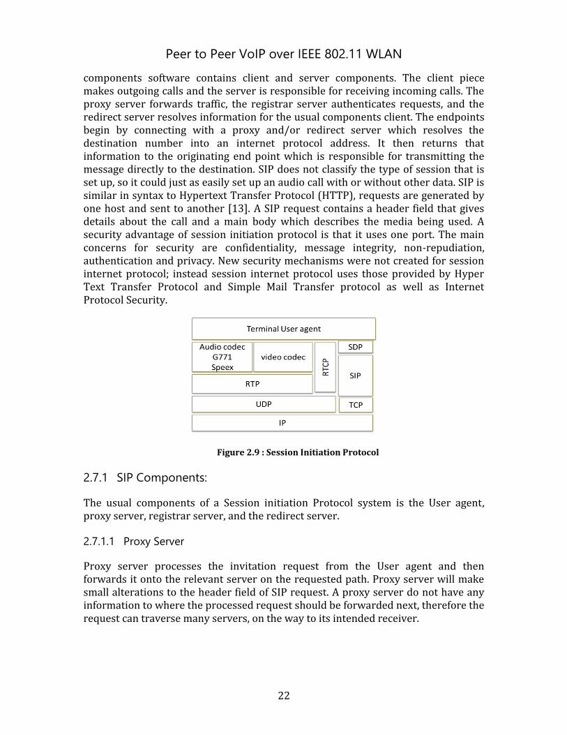
2.7.1.1 Proxy Server
Proxy server processes the invitation request from the User agent and then forwards it onto the relevant server on the requested path. Proxy server will make small alterations to the header field of SIP request. A proxy server do not have any information to where the processed request should be forwarded next, therefore the request can traverse many servers, on the way to its intended receiver.
Peer to Peer VoIP over IEEE 802.11 WLAN
23
Figure 2.10 Proxy server
SIP specification defined by two types of proxies: state full proxy and state less proxy. State less proxy is just a simple message forwarder without saving any transaction context. When it receives a request from a node, the stateless proxy forwards the message in stateless fashion, means that once the message is forwarded the proxy will neglects event task .Simple forwarding allows for improved performance and growth of network, but has some consequences such as the proxy application do not have any information if a transaction was successful or not. Stateless proxy also processes retransmission requests as if this is the first copy of the message it received.
Due to High-throughput and load balancing capability, stateless proxies are often used at the core of carrier and service provider networks assisting in forwarding SIP messages on the network.
Stateful proxy processes the transactions preferably as individual messages. Proxy server manages two types of transactions: server transactions to receive requests and return responses and client transactions to send requests and receive responses. Server transaction processes incoming request and then forwards downstream. An incoming response is received by the client transaction and forwarded back to the server transaction. Stateful proxy is aware of the state of transaction and message history. It is possible to retransmit the data in case of message loss. Stateful proxy is able to generate CANCEL requests and can locally process incoming CANCEL requests.
However Stateful behaviors have some disadvantages in network such as memory consumption, throughputs and underlying SIP stack complexity. Proxy requires the SIP stack to be more modular and export more layers of API than a User agent oriented stack.
Peer to Peer VoIP over IEEE 802.11 WLAN
24
Redirect Server:
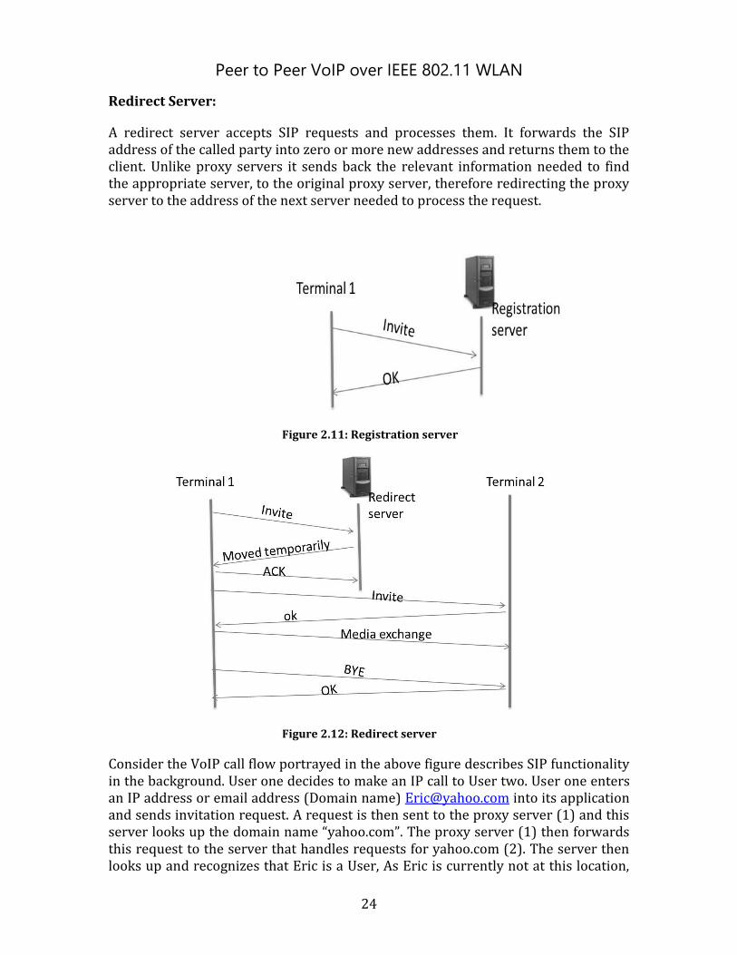
A redirect server accepts SIP requests and processes them. It forwards the SIP address of the called party into zero or more new addresses and returns them to the client. Unlike proxy servers it sends back the relevant information needed to find the appropriate server, to the original proxy server, therefore redirecting the proxy server to the address of the next server needed to process the request.
Figure 2.11: Registration server
Figure 2.12: Redirect server
Consider the VoIP call flow portrayed in the above figure describes SIP functionality in the background. User one decides to make an IP call to User two. User one enters an IP address or email address (Domain name) [email protected] into its application and sends invitation request. A request is then sent to the proxy server (1) and this server looks up the domain name “yahoo.com”. The proxy server (1) then forwards this request to the server that handles requests for yahoo.com (2). The server then looks up and recognizes that Eric is a User, As Eric is currently not at this location,
Peer to Peer VoIP over IEEE 802.11 WLAN
25
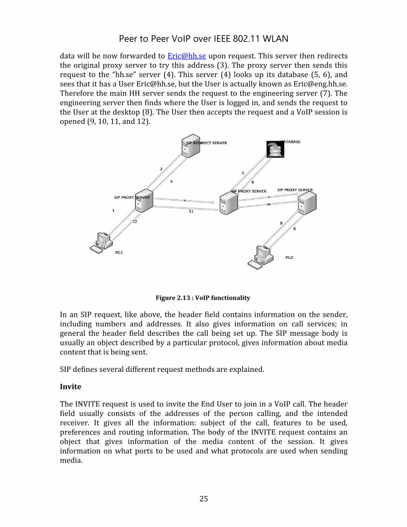
data will be now forwarded to [email protected] upon request. This server then redirects the original proxy server to try this address (3). The proxy server then sends this request to the “hh.se” server (4). This server (4) looks up its database (5, 6), and sees that it has a User [email protected], but the User is actually known as [email protected]. Therefore the main HH server sends the request to the engineering server (7). The engineering server then finds where the User is logged in, and sends the request to the User at the desktop (8). The User then accepts the request and a VoIP session is opened (9, 10, 11, and 12).
Figure 2.13 : VoIP functionality
In an SIP request, like above, the header field contains information on the sender, including numbers and addresses. It also gives information on call services; in general the header field describes the call being set up. The SIP message body is usually an object described by a particular protocol, gives information about media content that is being sent.
SIP defines several different request methods are explained.
Invite
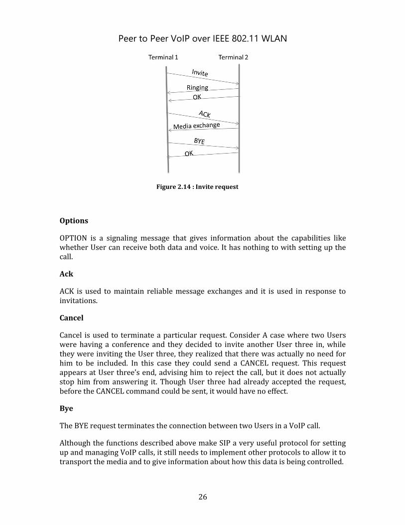
The INVITE request is used to invite the End User to join in a VoIP call. The header field usually consists of the addresses of the person calling, and the intended receiver. It gives all the information: subject of the call, features to be used, preferences and routing information. The body of the INVITE request contains an object that gives information of the media content of the session. It gives information on what ports to be used and what protocols are used when sending media.
Peer to Peer VoIP over IEEE 802.11 WLAN
26
Figure 2.14 : Invite request
Options
OPTION is a signaling message that gives information about the capabilities like whether User can receive both data and voice. It has nothing to with setting up the call.
Ack
ACK is used to maintain reliable message exchanges and it is used in response to invitations.
Cancel
Cancel is used to terminate a particular request. Consider A case where two Users were having a conference and they decided to invite another User three in, while they were inviting the User three, they realized that there was actually no need for him to be included. In this case they could send a CANCEL request. This request appears at User three’s end, advising him to reject the call, but it does not actually stop him from answering it. Though User three had already accepted the request, before the CANCEL command could be sent, it would have no effect.
Bye
The BYE request terminates the connection between two Users in a VoIP call.
Although the functions described above make SIP a very useful protocol for setting up and managing VoIP calls, it still needs to implement other protocols to allow it to transport the media and to give information about how this data is being controlled.
Peer to Peer VoIP over IEEE 802.11 WLAN
27
2.7.2 REAL TIME TRANSPORT PROTOCOL (RTP):
Real time transport protocol provides general transport capabilities for the multimedia applications, including both stream based applications and conversational applications.
RTP works in combination with the User Datagram Protocol to transfer the data packets to the receiver node. VoIP data is inserted into data packets using the RTP protocol, which are then enclosed inside the UDP packets, are then transmitted to the receiving end .VoIP uses UDP protocol, because it transmits the voice data rapidly. Packet loss and delay jitter are the main problems when we send directly, by using UDP. For overcoming packet loss, a retransmission mechanism is not possible in VOIP for real-time services.
To overcome this problem, the receiver must know when the packet is sent. By using time stamping on the data packets while sending we can know when the data is sent at the receiver side. For this we are using a separate protocol called RTP.
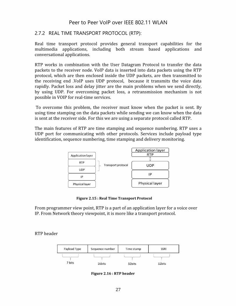
The main features of RTP are time stamping and sequence numbering. RTP uses a UDP port for communicating with other protocols. Services include payload type identification, sequence numbering, time stamping and delivery monitoring.
Figure 2.15 : Real Time Transport Protocol
From programmer view point, RTP is a part of an application layer for a voice over IP. From Network theory viewpoint, it is more like a transport protocol.
RTP header
Figure 2.16 : RTP header
Peer to Peer VoIP over IEEE 802.11 WLAN
28
Synchronization source identifier:
This is different from an IP address, the sender chooses a random number while using. The main use of SSRI is to identify a particular RTP stream between 2 hosts, which is for identifying the source of the RTP stream.
Payload:
In the RTP header, pay load indicates type of encoding used for the multimedia stream (audio/video). It is allowed to send the payload size as 7 bits (27= 128). If a sender changes the payload type on fly, it should be updated in the pay load header, so that the receiver will adjust the VOCODER as per the encoding technique updated. In the RTP payload header we can send 128 types of payload types, some of them are standardized and the remaining are free.
Ex: Payload: 0 – PCM µ - law
7 – LPC (8 kHz)
14 - mpeg(90 khz)-audio
31 - mpeg-1 video
32-mpeg-2 video
Sequence number:
Incremented by 1 for each RTP packet and sequence number is used for detecting packet loss.
Time stamping:
It denotes sampling instant of first byte in the RTP data and to remove packet jitter. It is derived from sampling clock at the sender.
2.7.3 RTCP
1. Used during multicast audio video transmission 2. RTCP packets are distributed to all the participants using IP multicast 3. Distinguished from RTP through the use of distinct port numbers 4. RTCP packets contains sender receiver reports
- Number of packets sent - Number of packets lost - Inter arrival time jitter
5. Different applications use different algorithms to use RTCP methods

Peer to Peer VoIP over IEEE 802.11 WLAN
29
Internally RTP used in cooperation with RTCP. RTP transports audio packets over the internet. RTCP responsible for monitoring the transmitting statistics and maintaining QOS
RTCP packets types: Receiver reception packets, Sender report packets
We can use this information to synch different media streams within a RTP session.

Peer to Peer VoIP over IEEE 802.11 WLAN
30
Peer to Peer VoIP over IEEE 802.11 WLAN
31
3 Solution Principles and Implementation
3.1 Solution
The aim of our project is to establish a VoIP session between Wi-Fi enabled devices when there is no access-point or network operator availability. For achieving this, group formation can be done between Wi-Fi enabled devices. After successful Group formation and to maintain communication between the devices, a VoIP Session could be established using developed SIP application..
3.1.1 Group formation
Two available standards, Wi-Fi direct or ad-hoc network are considered for the Group formation Procedure without access point between any Wi-Fi certified devices. As discussed, Wi-Fi direct can be used for peer to peer group formation between Wi-Fi equipped devices [6] using the device discovery and group formation procedures. We are using AM37x evaluation kit from the Texas instruments [15]. The wireless card included in this kit is WL1271 [15]. The current driver for this wireless card does not have the updated drivers with the capability to implement Wi-Fi direct standard on evaluation kit. The Android Operating system used on the evaluation Kit (AM37x) does not have any support for the ad-hoc mode for security reasons. The solution came through the use of an application downloaded from the Android Market: Barnacle, which has a main purpose to share the Wi-Fi connection of the device to its connected device using this application it is possible to set the ad-hoc mode on the evaluation kit which was described in the section [3.4]. We created an ad-hoc network by forming a group in which one device acts as access-point and other can connect to it, to get an IP address from the Access Point Device. In our thesis work, ad-Hoc network is formed between two nodes. Once the client device gets an address from the Access Point device, a voice call could be established from one Peer to another.
The following section will explain two different test scenarios to achieve communication between Wi-Fi enabled devices. For a clear understanding of our approach, we defined two different scenarios of communication between two nodes:
1) Communication establishment between two de-centralized nodes 2) Communication establishment between two nodes in a centralized node.
3.1.2 Test set-up
3.1.2.1 Test scenario I
In this test scenario we connected our devices to one Access-point in a centralized network as shown in Figure 2.17. In centralized network, connected devices will get an IP address from the access-point. Using this IP address a voice call can be established between the connected devices.
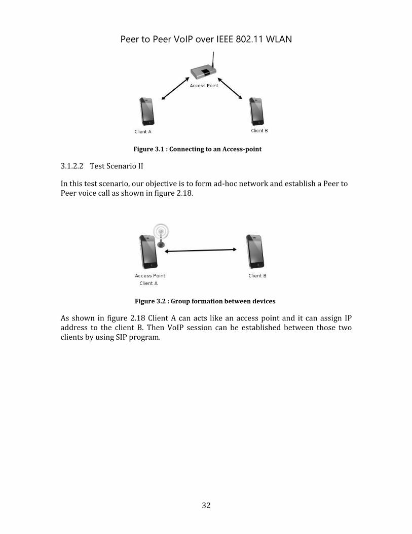
Peer to Peer VoIP over IEEE 802.11 WLAN
32
Figure 3.1 : Connecting to an Access-point
3.1.2.2 Test Scenario II
In this test scenario, our objective is to form ad-hoc network and establish a Peer to Peer voice call as shown in figure 2.18.
Figure 3.2 : Group formation between devices
As shown in figure 2.18 Client A can acts like an access point and it can assign IP address to the client B. Then VoIP session can be established between those two clients by using SIP program.
Peer to Peer VoIP over IEEE 802.11 WLAN
33
3.2 Implementation of solution
In this project, we used Texas Instrument's AM37 Evaluation kit. To prepare the hardware for the Application development, we followed a step by step procedure as shown in Figure 3.1.
Figure 3.3 : Getting hardware ready for experiment (Tree view)
3.2.1 Setting host PC
We started with setting up a host PC with Ubuntu 32 bit Operating system which is recommended by Texas instruments. Ubuntu is good for application development and also it is open source and flexible.
3.2.2 Hardware description
In this project we used AM/DM 37x EVM from “Mistral solutions”. It is a highly integrated development platform and it is easy-to-use. This platform is based on TEXAS INSTRUMENTS's AM/DM 37x Sitara Microprocessor. This EVM is one of the best development platforms for developing wireless/multimedia based applications. And also it has multiple display outputs like VGA LCD, DVI and S-Video. The AM/DM37x EVM platform helps developers to develop the next generation wireless devices and developers can enjoy the benefits of faster User interfaces, speed data access and a robust evaluation environment.
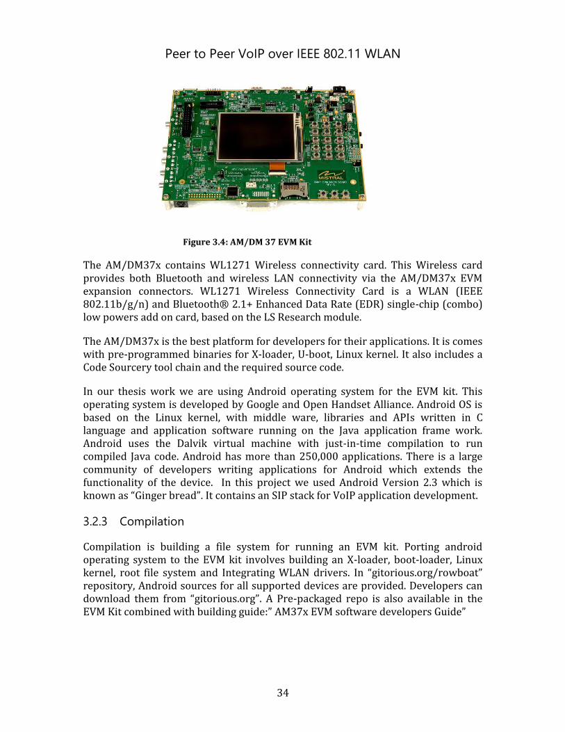
Peer to Peer VoIP over IEEE 802.11 WLAN
34
Figure 3.4: AM/DM 37 EVM Kit
The AM/DM37x contains WL1271 Wireless connectivity card. This Wireless card provides both Bluetooth and wireless LAN connectivity via the AM/DM37x EVM expansion connectors. WL1271 Wireless Connectivity Card is a WLAN (IEEE 802.11b/g/n) and Bluetooth® 2.1+ Enhanced Data Rate (EDR) single-chip (combo) low powers add on card, based on the LS Research module.
The AM/DM37x is the best platform for developers for their applications. It is comes with pre-programmed binaries for X-loader, U-boot, Linux kernel. It also includes a Code Sourcery tool chain and the required source code.
In our thesis work we are using Android operating system for the EVM kit. This operating system is developed by Google and Open Handset Alliance. Android OS is based on the Linux kernel, with middle ware, libraries and APIs written in C language and application software running on the Java application frame work. Android uses the Dalvik virtual machine with just-in-time compilation to run compiled Java code. Android has more than 250,000 applications. There is a large community of developers writing applications for Android which extends the functionality of the device. In this project we used Android Version 2.3 which is known as “Ginger bread”. It contains an SIP stack for VoIP application development.
3.2.3 Compilation
Compilation is building a file system for running an EVM kit. Porting android operating system to the EVM kit involves building an X-loader, boot-loader, Linux kernel, root file system and Integrating WLAN drivers. In “gitorious.org/rowboat” repository, Android sources for all supported devices are provided. Developers can download them from “gitorious.org”. A Pre-packaged repo is also available in the EVM Kit combined with building guide:” AM37x EVM software developers Guide”
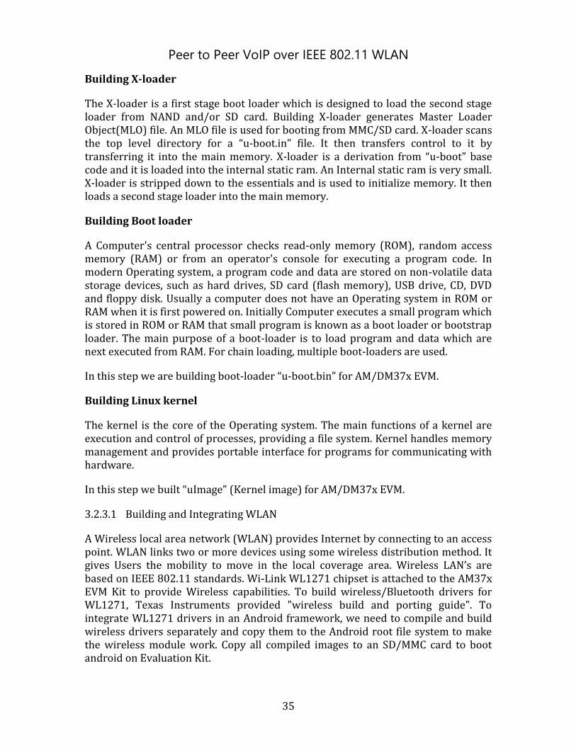
Peer to Peer VoIP over IEEE 802.11 WLAN
35
Building X-loader
The X-loader is a first stage boot loader which is designed to load the second stage loader from NAND and/or SD card. Building X-loader generates Master Loader Object(MLO) file. An MLO file is used for booting from MMC/SD card. X-loader scans the top level directory for a “u-boot.in” file. It then transfers control to it by transferring it into the main memory. X-loader is a derivation from “u-boot” base code and it is loaded into the internal static ram. An Internal static ram is very small. X-loader is stripped down to the essentials and is used to initialize memory. It then loads a second stage loader into the main memory.
Building Boot loader
A Computer's central processor checks read-only memory (ROM), random access memory (RAM) or from an operator's console for executing a program code. In modern Operating system, a program code and data are stored on non-volatile data storage devices, such as hard drives, SD card (flash memory), USB drive, CD, DVD and floppy disk. Usually a computer does not have an Operating system in ROM or RAM when it is first powered on. Initially Computer executes a small program which is stored in ROM or RAM that small program is known as a boot loader or bootstrap loader. The main purpose of a boot-loader is to load program and data which are next executed from RAM. For chain loading, multiple boot-loaders are used.
In this step we are building boot-loader “u-boot.bin” for AM/DM37x EVM.
Building Linux kernel
The kernel is the core of the Operating system. The main functions of a kernel are execution and control of processes, providing a file system. Kernel handles memory management and provides portable interface for programs for communicating with hardware.
In this step we built “uImage” (Kernel image) for AM/DM37x EVM.
3.2.3.1 Building and Integrating WLAN
A Wireless local area network (WLAN) provides Internet by connecting to an access point. WLAN links two or more devices using some wireless distribution method. It gives Users the mobility to move in the local coverage area. Wireless LAN’s are based on IEEE 802.11 standards. Wi-Link WL1271 chipset is attached to the AM37x EVM Kit to provide Wireless capabilities. To build wireless/Bluetooth drivers for WL1271, Texas Instruments provided "wireless build and porting guide". To integrate WL1271 drivers in an Android framework, we need to compile and build wireless drivers separately and copy them to the Android root file system to make the wireless module work. Copy all compiled images to an SD/MMC card to boot android on Evaluation Kit.
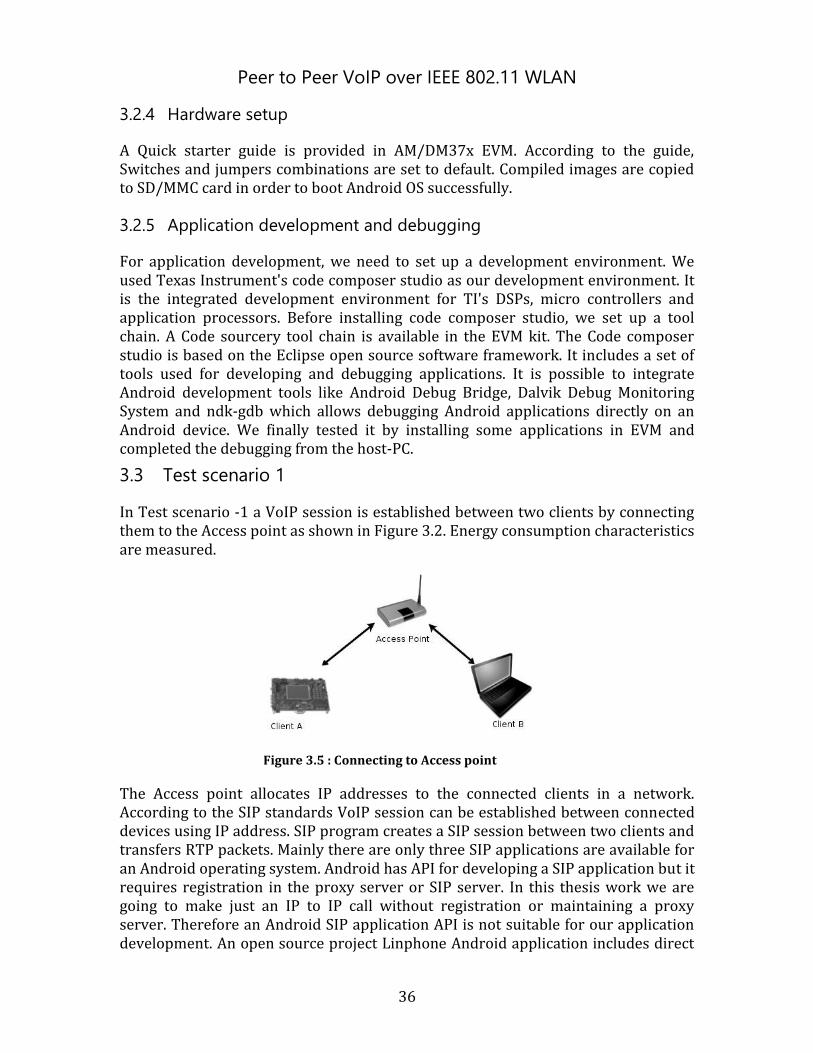
Peer to Peer VoIP over IEEE 802.11 WLAN
36
3.2.4 Hardware setup
A Quick starter guide is provided in AM/DM37x EVM. According to the guide, Switches and jumpers combinations are set to default. Compiled images are copied to SD/MMC card in order to boot Android OS successfully.
3.2.5 Application development and debugging
For application development, we need to set up a development environment. We used Texas Instrument's code composer studio as our development environment. It is the integrated development environment for TI's DSPs, micro controllers and application processors. Before installing code composer studio, we set up a tool chain. A Code sourcery tool chain is available in the EVM kit. The Code composer studio is based on the Eclipse open source software framework. It includes a set of tools used for developing and debugging applications. It is possible to integrate Android development tools like Android Debug Bridge, Dalvik Debug Monitoring System and ndk-gdb which allows debugging Android applications directly on an Android device. We finally tested it by installing some applications in EVM and completed the debugging from the host-PC.
3.3 Test scenario 1
In Test scenario -1 a VoIP session is established between two clients by connecting them to the Access point as shown in Figure 3.2. Energy consumption characteristics are measured.
Figure 3.5 : Connecting to Access point
The Access point allocates IP addresses to the connected clients in a network. According to the SIP standards VoIP session can be established between connected devices using IP address. SIP program creates a SIP session between two clients and transfers RTP packets. Mainly there are only three SIP applications are available for an Android operating system. Android has API for developing a SIP application but it requires registration in the proxy server or SIP server. In this thesis work we are going to make just an IP to IP call without registration or maintaining a proxy server. Therefore an Android SIP application API is not suitable for our application development. An open source project Linphone Android application includes direct
Peer to Peer VoIP over IEEE 802.11 WLAN
37
IP to IP call in local network. This SIP application can establish IP to IP call between two devices.
In Figure 3.3, Test scenario -1 is illustrated as shown in the flow chart. In this Test scenario we installed Linphone application in EVM Kit and laptop. EVM Kit and laptop are connected to the same network and IP addresses are 192.168.2.5 and 192.168.2.11 respectively. According to SIP standards a call has been made by sip:[email protected] to sip:[email protected]. VoIP performance is measured by changing different codecs and energy consumption is calculated using Power Tutor [17].
Figure 3.6 : Test scenario-1
3.4 Test scenario 2
To develop an android application for making an ad-hoc SIP call is quite complex. To achieve this, the first task is to setup an android device in ad-hoc mode and establish a SIP call between android devices those are in the ad-hoc network.
In Test scenario -2, we create an ad-hoc network between devices without using Access point. In Figure 3.4 Test scenario -2 is illustrated using a flowchart. In this group formation one device setup in an ad-hoc mode and other devices act as stations.
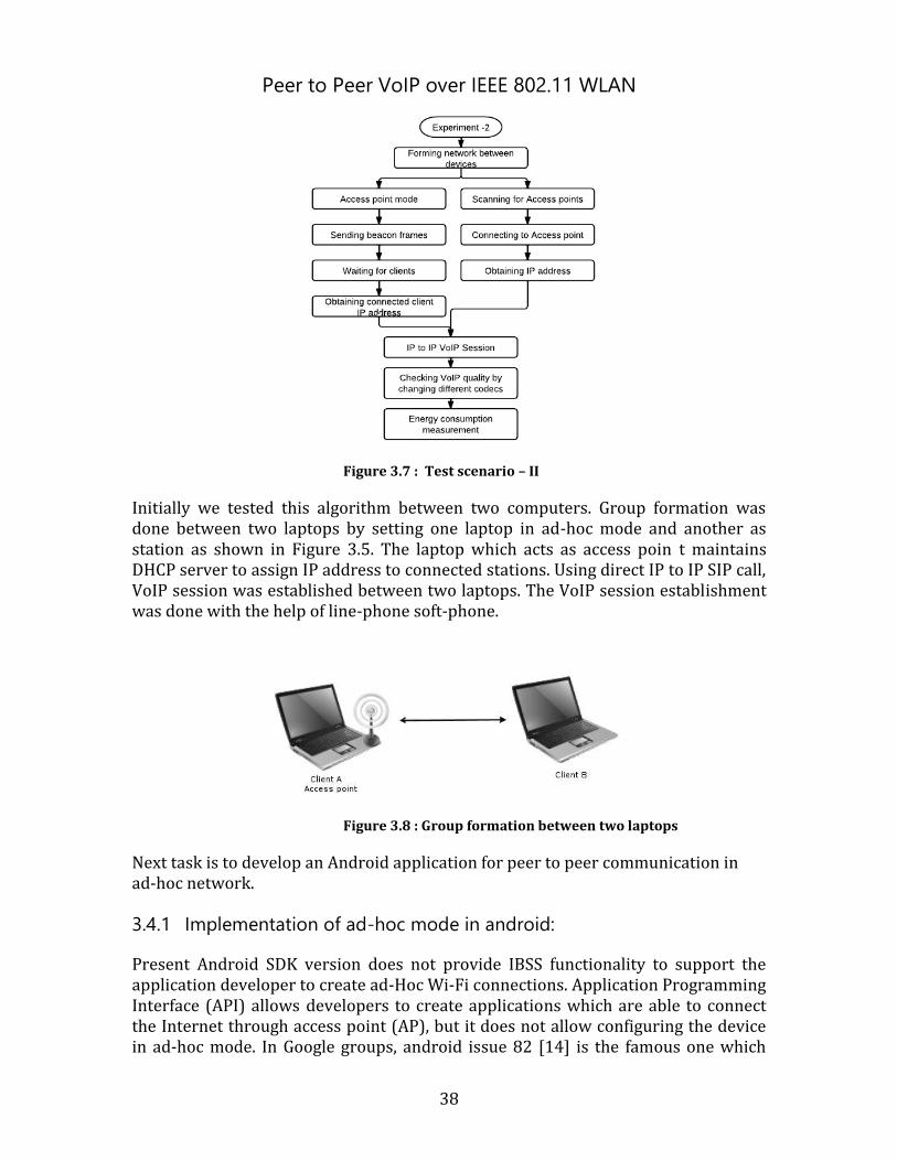
Peer to Peer VoIP over IEEE 802.11 WLAN
38
Figure 3.7 : Test scenario – II
Initially we tested this algorithm between two computers. Group formation was done between two laptops by setting one laptop in ad-hoc mode and another as station as shown in Figure 3.5. The laptop which acts as access poin t maintains DHCP server to assign IP address to connected stations. Using direct IP to IP SIP call, VoIP session was established between two laptops. The VoIP session establishment was done with the help of line-phone soft-phone.
Figure 3.8 : Group formation between two laptops
Next task is to develop an Android application for peer to peer communication in ad-hoc network.
3.4.1 Implementation of ad-hoc mode in android:
Present Android SDK version does not provide IBSS functionality to support the application developer to create ad-Hoc Wi-Fi connections. Application Programming Interface (API) allows developers to create applications which are able to connect the Internet through access point (AP), but it does not allow configuring the device in ad-hoc mode. In Google groups, android issue 82 [14] is the famous one which
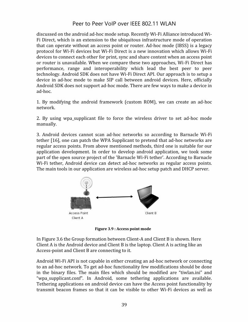
Peer to Peer VoIP over IEEE 802.11 WLAN
39
discussed on the android ad-hoc mode setup. Recently Wi-Fi Alliance introduced Wi-Fi Direct, which is an extension to the ubiquitous infrastructure mode of operation that can operate without an access point or router. Ad-hoc mode (IBSS) is a legacy protocol for Wi-Fi devices but Wi-Fi Direct is a new innovation which allows Wi-Fi devices to connect each other for print, sync and share content when an access point or router is unavailable. When we compare these two approaches, Wi-Fi Direct has performance, range and interoperability which lead the best peer to peer technology. Android SDK does not have Wi-Fi Direct API. Our approach is to setup a device in ad-hoc mode to make SIP call between android devices. Here, officially Android SDK does not support ad-hoc mode. There are few ways to make a device in ad-hoc.
1. By modifying the android framework (custom ROM), we can create an ad-hoc network.
2. By using wpa_supplicant file to force the wireless driver to set ad-hoc mode manually.
3. Android devices cannot scan ad-hoc networks so according to Barnacle Wi-Fi tether [16], one can patch the WPA Supplicant to pretend that ad-hoc networks are regular access points. From above mentioned methods, third one is suitable for our application development. In order to develop android application, we took some part of the open source project of the 'Barnacle Wi-Fi tether'. According to Barnacle Wi-Fi tether, Android device can detect ad-hoc networks as regular access points. The main tools in our application are wireless ad-hoc setup patch and DHCP server.
Figure 3.9 : Access point mode
In Figure 3.6 the Group formation between Client-A and Client B is shown. Here Client A is the Android device and Client B is the laptop. Client A is acting like an Access-point and Client B are connecting to it.
Android Wi-Fi API is not capable in either creating an ad-hoc network or connecting to an ad-hoc network. To get ad-hoc functionality few modifications should be done in the binary files. The main files which should be modified are “tiwlan.ini” and “wpa_supplicant.conf”. In Android, some tethering applications are available. Tethering applications on android device can have the Access point functionality by transmit beacon frames so that it can be visible to other Wi-Fi devices as well as
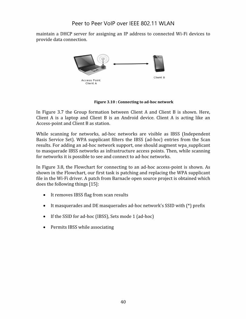
Peer to Peer VoIP over IEEE 802.11 WLAN
40
maintain a DHCP server for assigning an IP address to connected Wi-Fi devices to provide data connection.
Figure 3.10 : Connecting to ad-hoc network
In Figure 3.7 the Group formation between Client A and Client B is shown. Here, Client A is a laptop and Client B is an Android device. Client A is acting like an Access-point and Client B as station.
While scanning for networks, ad-hoc networks are visible as IBSS (Independent Basis Service Set). WPA supplicant filters the IBSS (ad-hoc) entries from the Scan results. For adding an ad-hoc network support, one should augment wpa_supplicant to masquerade IBSS networks as infrastructure access points. Then, while scanning for networks it is possible to see and connect to ad-hoc networks.
In Figure 3.8, the Flowchart for connecting to an ad-hoc access-point is shown. As shown in the Flowchart, our first task is patching and replacing the WPA supplicant file in the Wi-Fi driver. A patch from Barnacle open source project is obtained which does the following things [15]:
It removes IBSS flag from scan results
It masquerades and DE masquerades ad-hoc network's SSID with (*) prefix
If the SSID for ad-hoc (IBSS), Sets mode 1 (ad-hoc)
Permits IBSS while associating
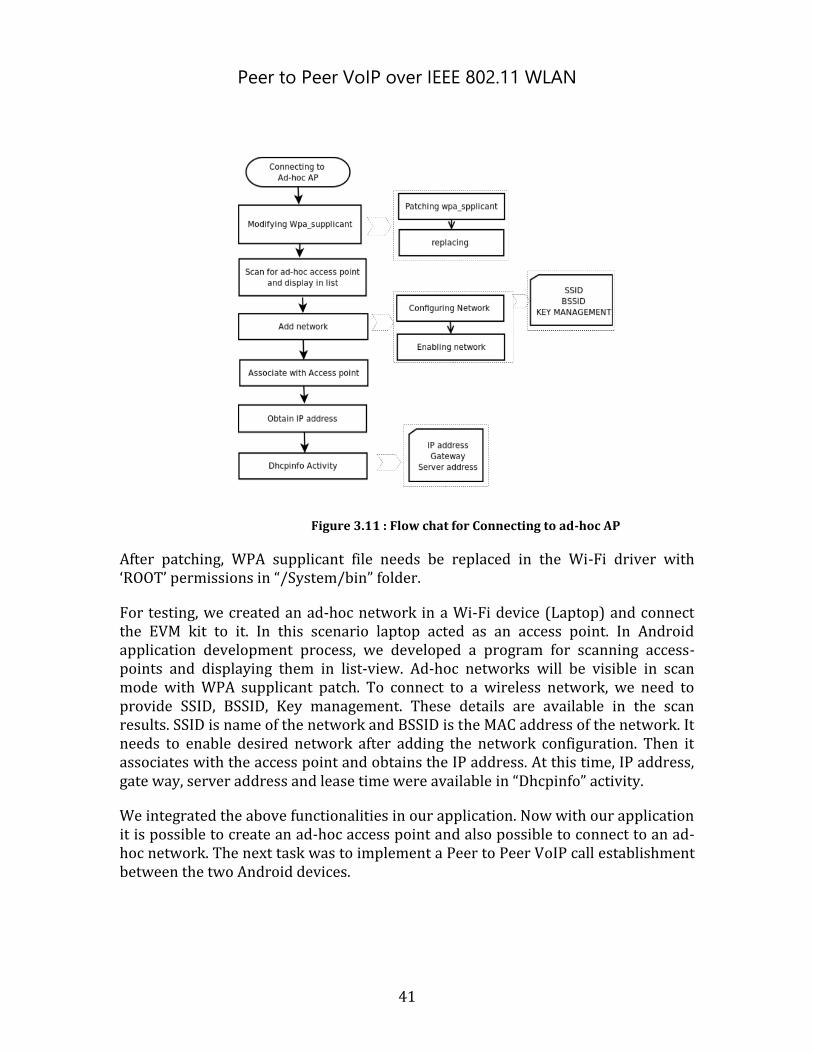
Peer to Peer VoIP over IEEE 802.11 WLAN
41
Figure 3.11 : Flow chat for Connecting to ad-hoc AP
After patching, WPA supplicant file needs be replaced in the Wi-Fi driver with ‘ROOT’ permissions in “/System/bin” folder.
For testing, we created an ad-hoc network in a Wi-Fi device (Laptop) and connect the EVM kit to it. In this scenario laptop acted as an access point. In Android application development process, we developed a program for scanning access-points and displaying them in list-view. Ad-hoc networks will be visible in scan mode with WPA supplicant patch. To connect to a wireless network, we need to provide SSID, BSSID, Key management. These details are available in the scan results. SSID is name of the network and BSSID is the MAC address of the network. It needs to enable desired network after adding the network configuration. Then it associates with the access point and obtains the IP address. At this time, IP address, gate way, server address and lease time were available in “Dhcpinfo” activity.
We integrated the above functionalities in our application. Now with our application it is possible to create an ad-hoc access point and also possible to connect to an ad-hoc network. The next task was to implement a Peer to Peer VoIP call establishment between the two Android devices.
Peer to Peer VoIP over IEEE 802.11 WLAN
42
3.4.2 Implementation of SIP in Android:
SIP is an IETF defined signaling protocol for voice and video over IP. It is an open standard for Internet telephony. From version 2.3 or higher Android includes SIP protocol stack to support Internet telephony. Android SIP API does not provide direct IP to IP call in a local network so that we obtained some required code from the open source project of Linphone Android application [17]. In ad-hoc mode, each device communicates with another device directly so in order to establish a SIP call, each device must have an IP address according to the SIP standards. The main aim of the Android application is to be able to setup an android device in ad-hoc mode then other devices can scan and connect to the device. Host device or client can initiate SIP call.
According to solution for achieving peer-to-peer voice calling functionality, we have taken two test scenarios. First test scenario is to make voice call between two clients by using an Access-point and second test scenario is to form a group between clients by making one device as an access-point.
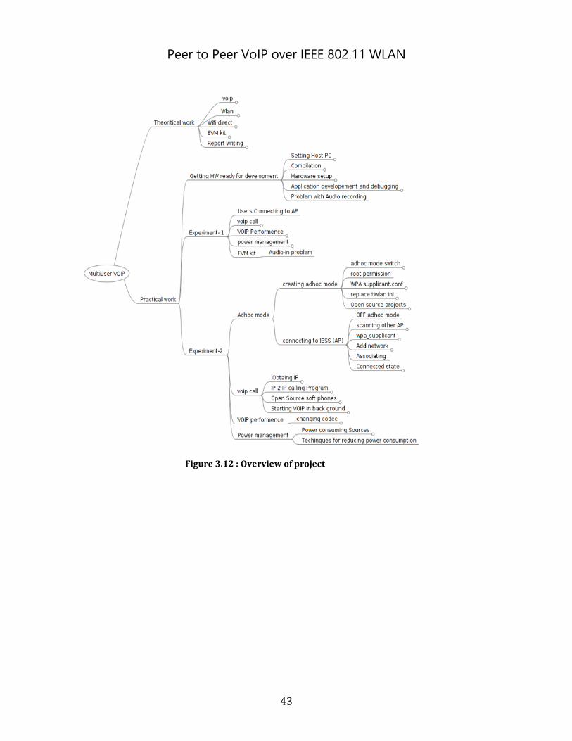
Peer to Peer VoIP over IEEE 802.11 WLAN
43
Figure 3.12 : Overview of project
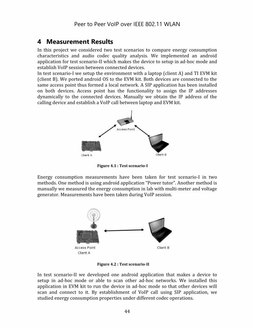
Peer to Peer VoIP over IEEE 802.11 WLAN
44
4 Measurement Results In this project we considered two test scenarios to compare energy consumption characteristics and audio codec quality analysis. We implemented an android application for test scenario-II which makes the device to setup in ad-hoc mode and establish VoIP session between connected devices. In test scenario-I we setup the environment with a laptop (client A) and TI EVM kit (client B). We ported android OS to the EVM kit. Both devices are connected to the same access point thus formed a local network. A SIP application has been installed on both devices. Access point has the functionality to assign the IP addresses dynamically to the connected devices. Manually we obtain the IP address of the calling device and establish a VoIP call between laptop and EVM kit.
Figure 4.1 : Test scenario-I
Energy consumption measurements have been taken for test scenario-I in two methods. One method is using android application “Power tutor”. Another method is manually we measured the energy consumption in lab with multi-meter and voltage generator. Measurements have been taken during VoIP session.
Figure 4.2 : Test scenario-II
In test scenario-II we developed one android application that makes a device to setup in ad-hoc mode or able to scan other ad-hoc networks. We installed this application in EVM kit to run the device in ad-hoc mode so that other devices will scan and connect to it. By establishment of VoIP call using SIP application, we studied energy consumption properties under different codec operations.
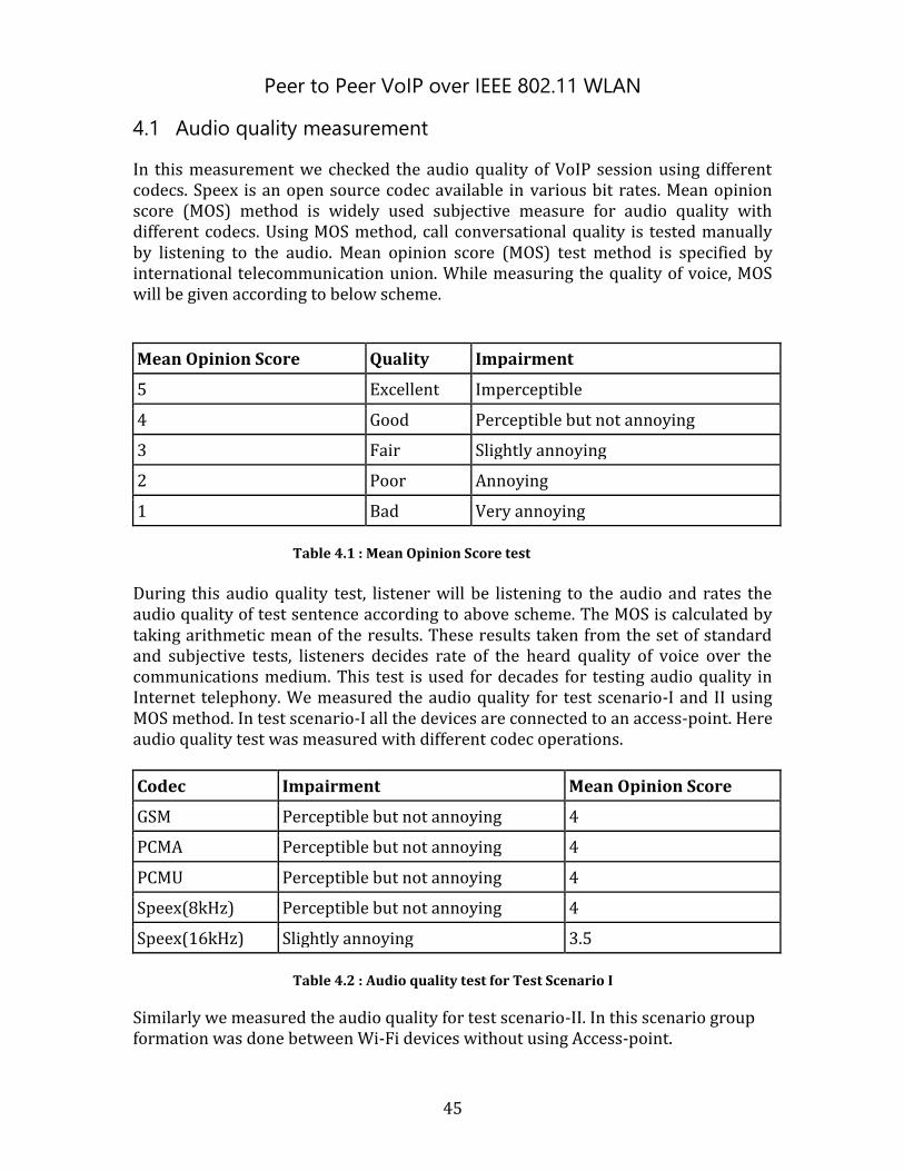
Peer to Peer VoIP over IEEE 802.11 WLAN
45
4.1 Audio quality measurement
In this measurement we checked the audio quality of VoIP session using different codecs. Speex is an open source codec available in various bit rates. Mean opinion score (MOS) method is widely used subjective measure for audio quality with different codecs. Using MOS method, call conversational quality is tested manually by listening to the audio. Mean opinion score (MOS) test method is specified by international telecommunication union. While measuring the quality of voice, MOS will be given according to below scheme.
Mean Opinion Score Quality Impairment
5 Excellent Imperceptible
4 Good Perceptible but not annoying
3 Fair Slightly annoying
2 Poor Annoying
1 Bad Very annoying
Table 4.1 : Mean Opinion Score test
During this audio quality test, listener will be listening to the audio and rates the audio quality of test sentence according to above scheme. The MOS is calculated by taking arithmetic mean of the results. These results taken from the set of standard and subjective tests, listeners decides rate of the heard quality of voice over the communications medium. This test is used for decades for testing audio quality in Internet telephony. We measured the audio quality for test scenario-I and II using MOS method. In test scenario-I all the devices are connected to an access-point. Here audio quality test was measured with different codec operations.
Codec Impairment Mean Opinion Score
GSM Perceptible but not annoying 4
PCMA Perceptible but not annoying 4
PCMU Perceptible but not annoying 4
Speex(8kHz) Perceptible but not annoying 4
Speex(16kHz) Slightly annoying 3.5
Table 4.2 : Audio quality test for Test Scenario I
Similarly we measured the audio quality for test scenario-II. In this scenario group formation was done between Wi-Fi devices without using Access-point.
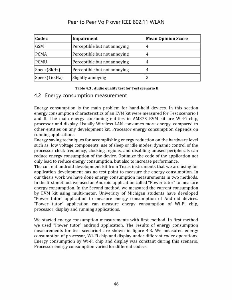
Peer to Peer VoIP over IEEE 802.11 WLAN
46
Codec Impairment Mean Opinion Score
GSM Perceptible but not annoying 4
PCMA Perceptible but not annoying 4
PCMU Perceptible but not annoying 4
Speex(8kHz) Perceptible but not annoying 4
Speex(16kHz) Slightly annoying 3
Table 4.3 : Audio quality test for Test scenario II
4.2 Energy consumption measurement
Energy consumption is the main problem for hand-held devices. In this section energy consumption characteristics of an EVM kit were measured for Test scenario I and II. The main energy consuming entities in AM37X EVM kit are Wi-Fi chip, processor and display. Usually Wireless LAN consumes more energy, compared to other entities on any development kit. Processor energy consumption depends on running applications. Energy saving techniques for accomplishing energy reduction on the hardware level such as: low voltage components, use of sleep or idle modes, dynamic control of the processor clock frequency, clocking regions, and disabling unused peripherals can reduce energy consumption of the device. Optimize the code of the application not only lead to reduce energy consumption, but also to increase performance. The current android development kit from Texas instruments that we are using for application development has no test point to measure the energy consumption. In our thesis work we have done energy consumption measurements in two methods. In the first method, we used an Android application called “Power tutor” to measure energy consumption. In the Second method, we measured the current consumption by EVM kit using multi-meter. University of Michigan students have developed “Power tutor” application to measure energy consumption of Android devices. “Power tutor” application can measure energy consumption of Wi-Fi chip, processor, display and running applications. We started energy consumption measurements with first method. In first method we used “Power tutor” android application. The results of energy consumption measurements for test scenario-I are shown in figure 4.3. We measured energy consumption of processor, Wi-Fi chip and display under different codec operations. Energy consumption by Wi-Fi chip and display was constant during this scenario. Processor energy consumption varied for different codecs.
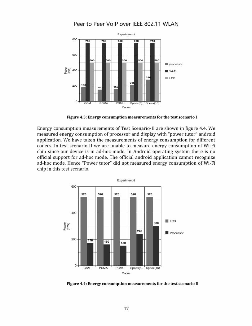
Peer to Peer VoIP over IEEE 802.11 WLAN
47
Figure 4.3: Energy consumption measurements for the test scenario I
Energy consumption measurements of Test Scenario-II are shown in figure 4.4. We measured energy consumption of processor and display with “power tutor” android application. We have taken the measurements of energy consumption for different codecs. In test scenario II we are unable to measure energy consumption of Wi-Fi chip since our device is in ad-hoc mode. In Android operating system there is no official support for ad-hoc mode. The official android application cannot recognize ad-hoc mode. Hence “Power tutor” did not measured energy consumption of Wi-Fi chip in this test scenario.
Figure 4.4: Energy consumption measurements for the test scenario II
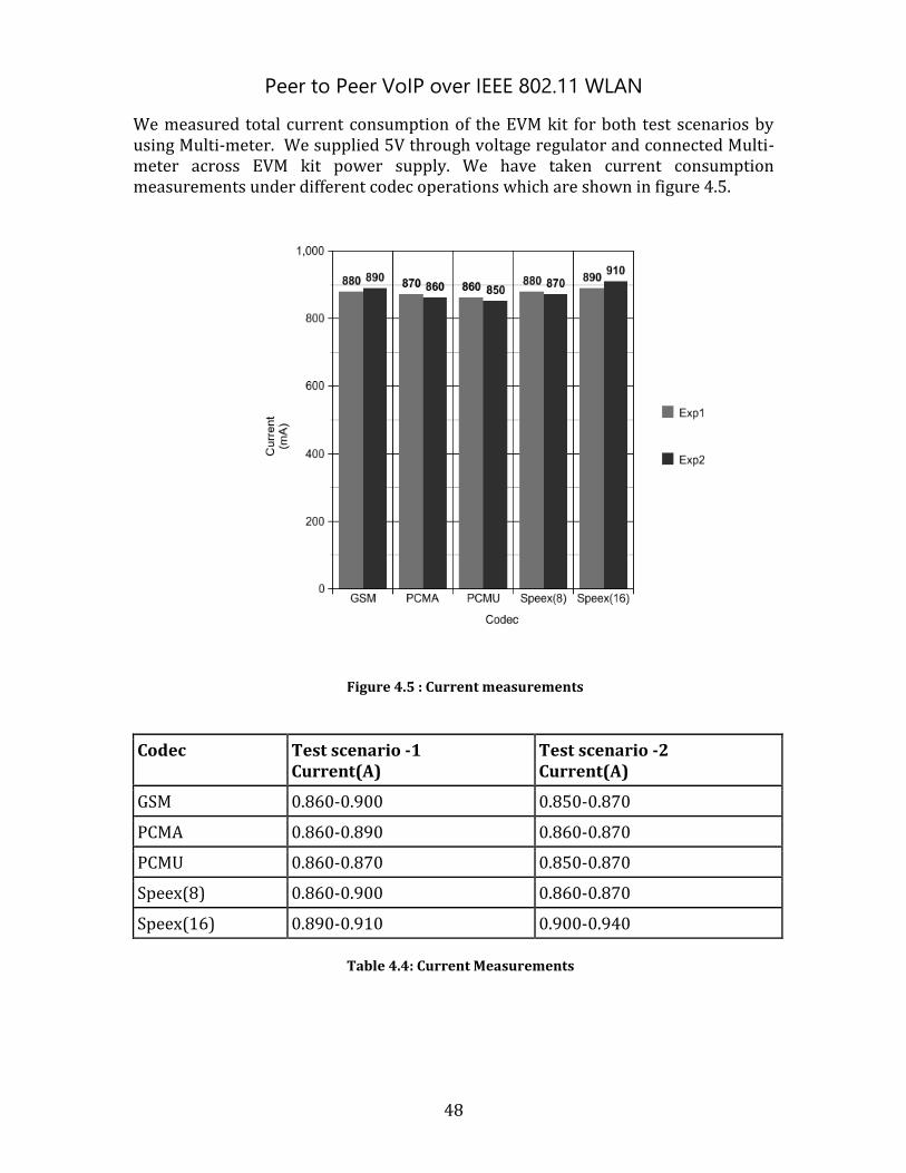
Peer to Peer VoIP over IEEE 802.11 WLAN
48
We measured total current consumption of the EVM kit for both test scenarios by using Multi-meter. We supplied 5V through voltage regulator and connected Multi-meter across EVM kit power supply. We have taken current consumption measurements under different codec operations which are shown in figure 4.5.
Figure 4.5 : Current measurements
Codec Test scenario -1 Current(A)
Test scenario -2 Current(A)
GSM 0.860-0.900 0.850-0.870
PCMA 0.860-0.890 0.860-0.870
PCMU 0.860-0.870 0.850-0.870
Speex(8) 0.860-0.900 0.860-0.870
Speex(16) 0.890-0.910 0.900-0.940
Table 4.4: Current Measurements
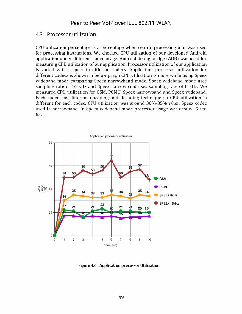
Peer to Peer VoIP over IEEE 802.11 WLAN
49
4.3 Processor utilization
CPU utilization percentage is a percentage when central processing unit was used for processing instructions. We checked CPU utilization of our developed Android application under different codec usage. Android debug bridge (ADB) was used for measuring CPU utilization of our application. Processor utilization of our application is varied with respect to different codecs. Application processor utilization for different codecs is shown in below graph CPU utilization is more while using Speex wideband mode comparing Speex narrowband mode. Speex wideband mode uses sampling rate of 16 kHz and Speex narrowband uses sampling rate of 8 kHz. We measured CPU utilization for GSM, PCMU, Speex narrowband and Speex wideband. Each codec has different encoding and decoding technique so CPU utilization is different for each codec. CPU utilization was around 30%-35% when Speex codec used in narrowband. In Speex wideband mode processor usage was around 50 to 65.
Figure 4.6 : Application processor Utilization

Peer to Peer VoIP over IEEE 802.11 WLAN
50
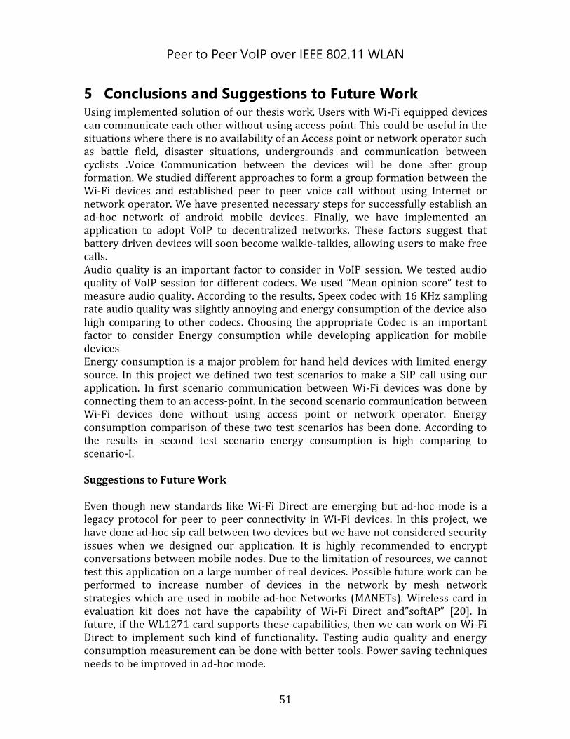
Peer to Peer VoIP over IEEE 802.11 WLAN
51
5 Conclusions and Suggestions to Future Work Using implemented solution of our thesis work, Users with Wi-Fi equipped devices can communicate each other without using access point. This could be useful in the situations where there is no availability of an Access point or network operator such as battle field, disaster situations, undergrounds and communication between cyclists .Voice Communication between the devices will be done after group formation. We studied different approaches to form a group formation between the Wi-Fi devices and established peer to peer voice call without using Internet or network operator. We have presented necessary steps for successfully establish an ad-hoc network of android mobile devices. Finally, we have implemented an application to adopt VoIP to decentralized networks. These factors suggest that battery driven devices will soon become walkie-talkies, allowing users to make free calls. Audio quality is an important factor to consider in VoIP session. We tested audio quality of VoIP session for different codecs. We used “Mean opinion score” test to measure audio quality. According to the results, Speex codec with 16 KHz sampling rate audio quality was slightly annoying and energy consumption of the device also high comparing to other codecs. Choosing the appropriate Codec is an important factor to consider Energy consumption while developing application for mobile devices Energy consumption is a major problem for hand held devices with limited energy source. In this project we defined two test scenarios to make a SIP call using our application. In first scenario communication between Wi-Fi devices was done by connecting them to an access-point. In the second scenario communication between Wi-Fi devices done without using access point or network operator. Energy consumption comparison of these two test scenarios has been done. According to the results in second test scenario energy consumption is high comparing to scenario-I. Suggestions to Future Work Even though new standards like Wi-Fi Direct are emerging but ad-hoc mode is a legacy protocol for peer to peer connectivity in Wi-Fi devices. In this project, we have done ad-hoc sip call between two devices but we have not considered security issues when we designed our application. It is highly recommended to encrypt conversations between mobile nodes. Due to the limitation of resources, we cannot test this application on a large number of real devices. Possible future work can be performed to increase number of devices in the network by mesh network strategies which are used in mobile ad-hoc Networks (MANETs). Wireless card in evaluation kit does not have the capability of Wi-Fi Direct and”softAP” [20]. In future, if the WL1271 card supports these capabilities, then we can work on Wi-Fi Direct to implement such kind of functionality. Testing audio quality and energy consumption measurement can be done with better tools. Power saving techniques needs to be improved in ad-hoc mode.

Peer to Peer VoIP over IEEE 802.11 WLAN
52

Peer to Peer VoIP over IEEE 802.11 WLAN
53
6 References [1] Amir Sinaeepourfard, Helmi Mohamed Hussain, “ Comparison of VoIP and
PSTN Services by Statistical Analysis ”, IEEE Student Conference on Research and Development, 2011.
[2] Edited by guy Pujolle, “IFIP TC6 Mobile IFIP TC6 International Conference on Mobile and Wireless Communications Networks, chapter 1, Pg no. [1-3]”, WCC 8th:2006 Santiago, Chile, ISBN 978-0-387-34634-2.
[3] Bob O'Hara, Al Petrick, “IEEE 802.11 handbook, A designer’s compilation”, IEEE Press, 1999.
[4] Henning Schulzrinne, Jonathan Rosenberg, “Signalling for IP telephony” Network Protocols, 1998. Proceedings. Sixth International Conference, 1998.
[5] William Stallings, “Data and Computer Communications”, 7th Edition, ISBN-10: 0131006819, May 2003.
[6] Wi-Fi alliance, “Wi-Fi Peer-to-Peer (P2P) Technical Specification 2010”, http://www.wi-fi.org/discover-and-learn/wi-fi-direct .
[7] Keith Shaw speech, Kelly Davis-Felner, “new Wi-Fi Direct specification”, Internet, NetworkWorld.com, October 2009, 17 min. http://www.networkworld.com/podcasts/panorama/2009/101409pan-wifidirect.html .
[8] Lisa Grantham, WMM Q&A, “Wi-Fi Alliance”, http://www.wi-fi.org/files/kc_8_WMM%20QandA_3-23-05.pdf, March 2005.
[9] Jeff Goldman, November 2009, “A Closer Look at Wi-Fi Direct, Wi-Fi Planet”, http://www.wi-fiplanet.com/news/article.php/3848451 .
[10] Maury Wright, “Wi-Fi Direct adds Peer-to-Peer Capabilities to Ubiquitous Wireless Network Technology”, http://www.digikey.com/us/en/techzone/wireless/resources/articles/Wi-Fi-Direct-adds-Peer-to-Peer-Capabilities.html .
[11] Daniel Camps-Mur, Xavier Perez-Costa, Sebastia Sallent-Ribes, “Designing Energy Efficient Access Points with Wi-Fi Direct”, http://www.campsmur.cat/files/wifi_direct_CN.pdf .
[12] Speex Audio codec, http://www.speex.org/docs/manual/speex-manual/node4.html#SECTION00420000000000000000 .
[13] XiaofeiLiao, Hai Jin, Chang Shu, “A Voice Gateway System Based on P2P SIP VoIP”, Pervasive Computing and Applications (ICPCA), 2011 6th International Conference, IEEE org.
[14] An Open Handset Alliance Project , “Android Ad-Hoc issue 82”, http://code.google.com/p/android/issues/detail?id=82, Google groups.
[15] Barnacle Wifi-Tether, “Ad-hoc in android” http://szym.net/2010/12/adhoc-wifi-in-android/#more-43 .
[16] Barnacle Wi-Fi tether, “Tethering application” http://szym.net/barnacle/ .

Peer to Peer VoIP over IEEE 802.11 WLAN
54
[17] Power tutor, “Energy measurement application”, http://ziyang.eecs.umich.edu/projects/powertutor/.
[18] EVM kit Description, “http://www.ti.com/tool/tmdsevm3730.” Texas Instruments
[19] Line-phone, “Free SIP VoIP client”, http://www.linphone.org/ .
[20] WLAN SoftAP, “Porting WLAN softAP to Android”, http://omappedia.org/wiki/Porting_WLAN_SoftAP_to_Android
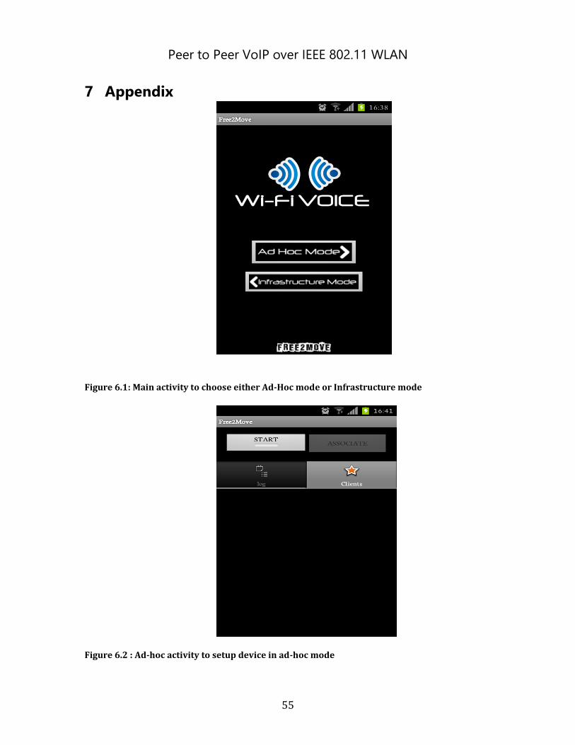
Peer to Peer VoIP over IEEE 802.11 WLAN
55
7 Appendix
Figure 6.1: Main activity to choose either Ad-Hoc mode or Infrastructure mode
Figure 6.2 : Ad-hoc activity to setup device in ad-hoc mode
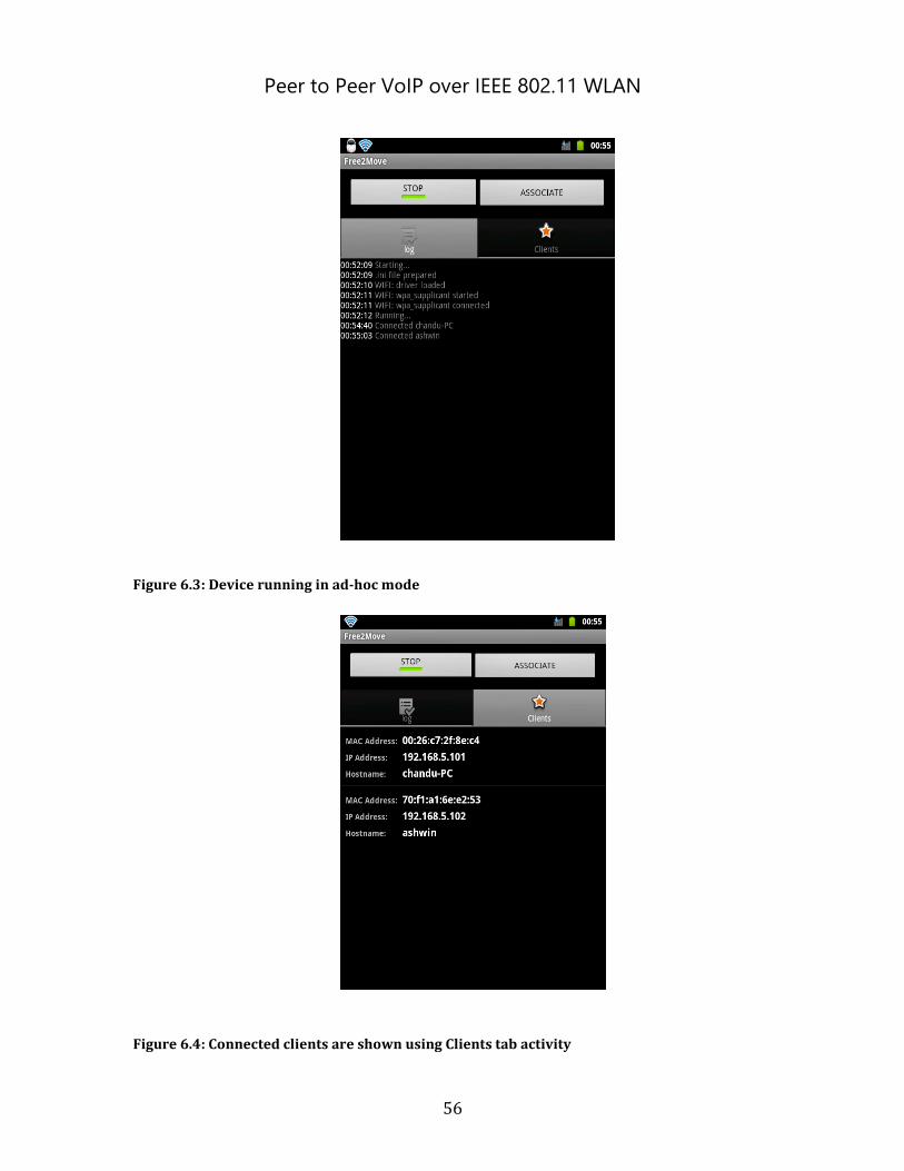
Peer to Peer VoIP over IEEE 802.11 WLAN
56
Figure 6.3: Device running in ad-hoc mode
Figure 6.4: Connected clients are shown using Clients tab activity
Peer to Peer VoIP over IEEE 802.11 WLAN
57
Figure 6.5 : Call activity by selecting specific client
Figure 6.6 : Signaling between user agents using SIP protocol
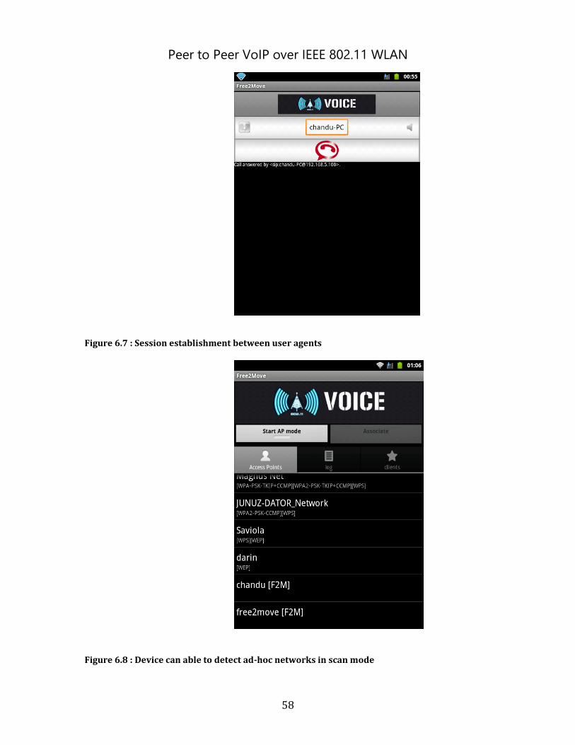
Peer to Peer VoIP over IEEE 802.11 WLAN
58
Figure 6.7 : Session establishment between user agents
Figure 6.8 : Device can able to detect ad-hoc networks in scan mode
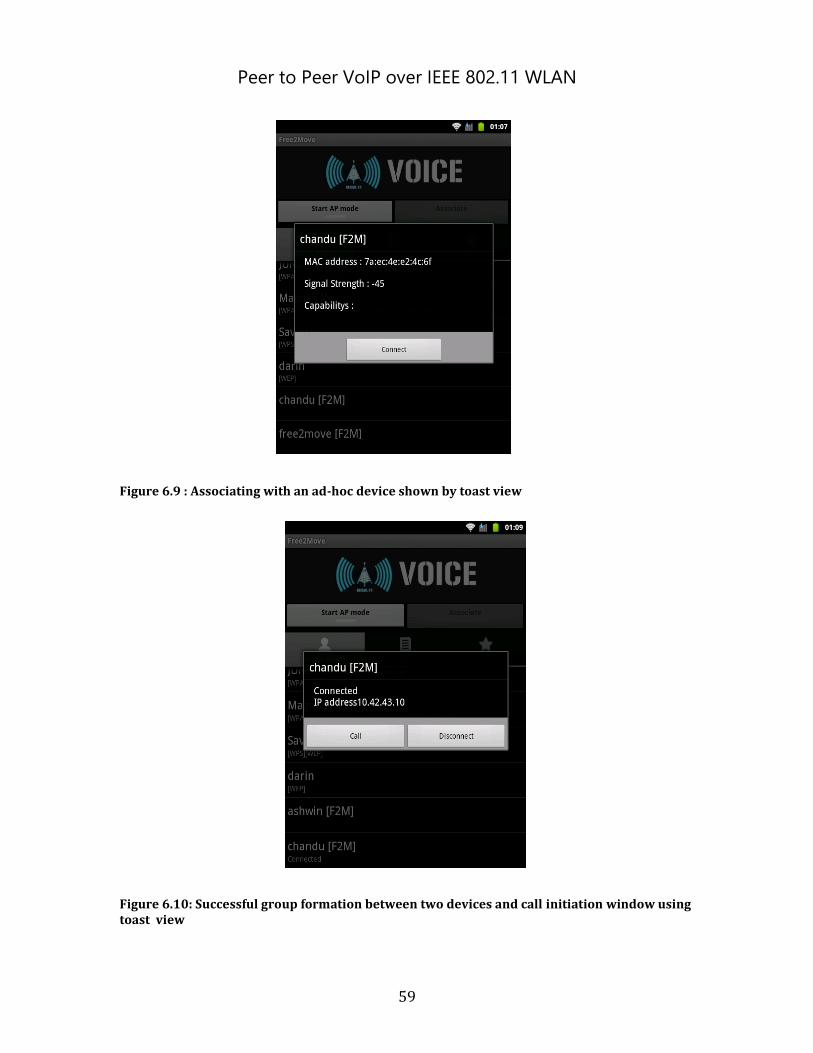
Peer to Peer VoIP over IEEE 802.11 WLAN
59
Figure 6.9 : Associating with an ad-hoc device shown by toast view
Figure 6.10: Successful group formation between two devices and call initiation window using toast view
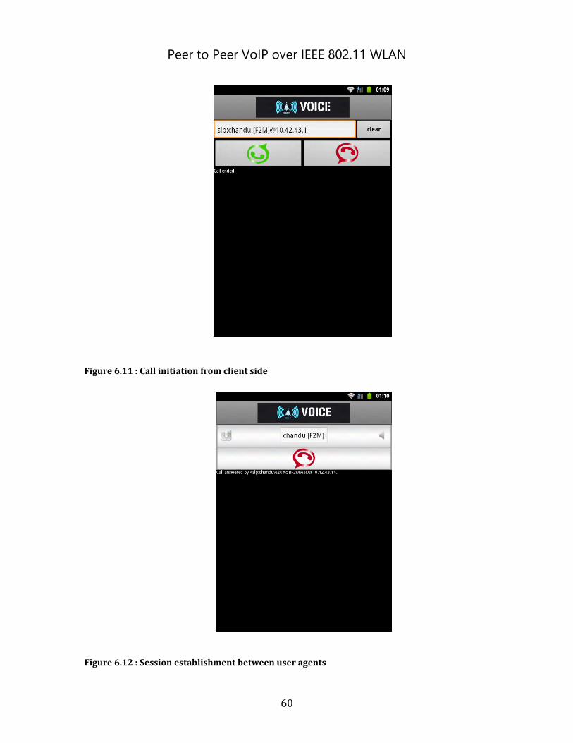
Peer to Peer VoIP over IEEE 802.11 WLAN
60
Figure 6.11 : Call initiation from client side
Figure 6.12 : Session establishment between user agents
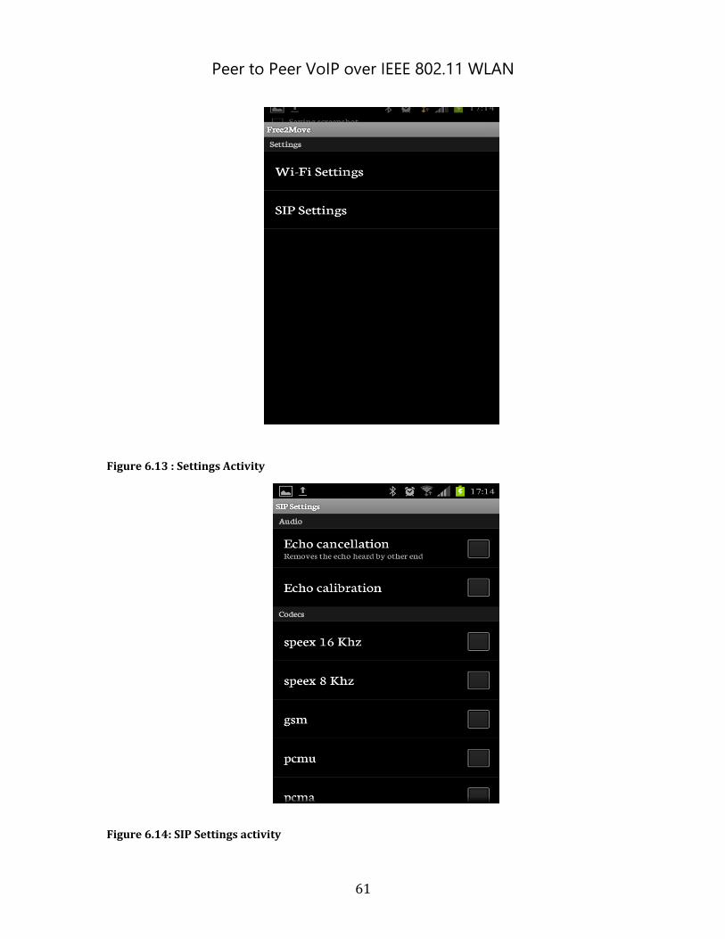
Peer to Peer VoIP over IEEE 802.11 WLAN
61
Figure 6.13 : Settings Activity
Figure 6.14: SIP Settings activity
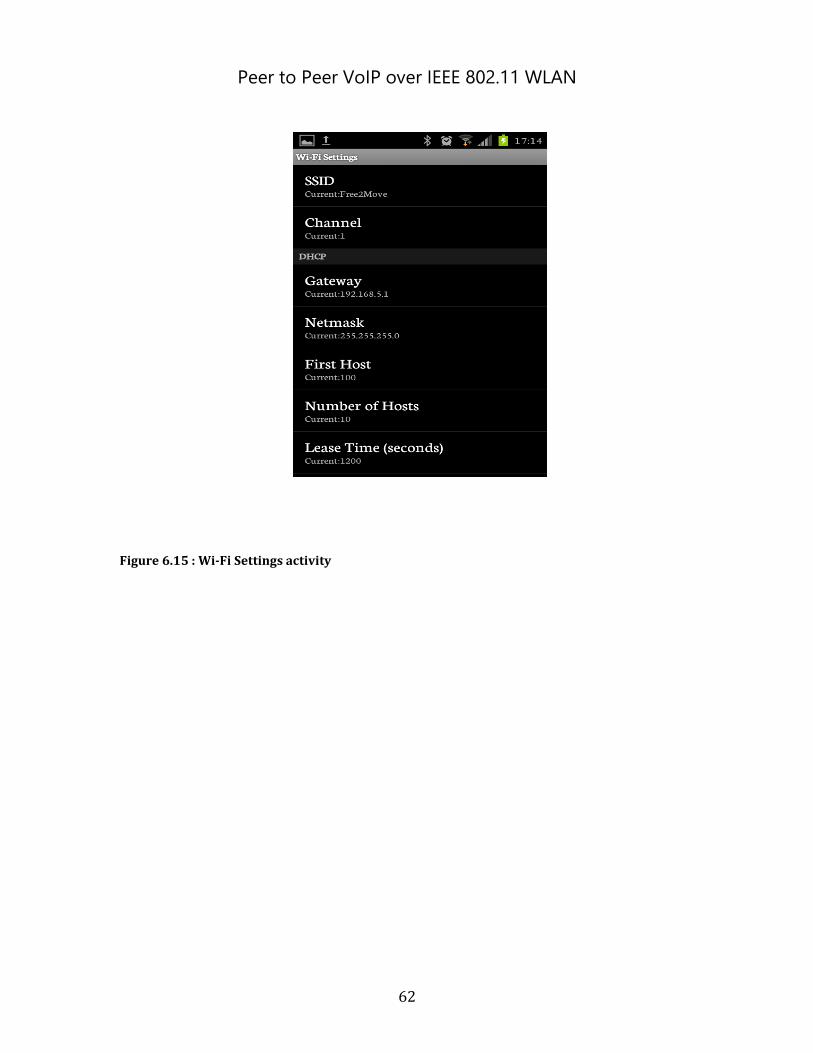
Peer to Peer VoIP over IEEE 802.11 WLAN
62
Figure 6.15 : Wi-Fi Settings activity

63
Presentation of the author(s)
Karunakar Antham [email protected] , +46735608912,
Master student in Embedded and Intelligent Systems, Halmstad University, Sweden Bachelors in Electronics and communication engineering, JNTU, India Research Interest: IP telephony, Internet real-time and multimedia communication systems, and peer-to-peer networks, Embedded Communications
Chandrashekar Reddy Palle [email protected] ,+46760878796 Master student in Embedded and intelligent student, Halmstad University, Sweden Bachelors in electronics and communication engineering, JNTU India Research interest: real time operating systems, Device driver programming for Linux ,Field bus(CAN Bus, profibus), Wireless LAN.
Ashwin kumar Mantoor, [email protected] , +46 739419986 Master Student in embedded and intelligent systems, Halmstad University Bachelors in Electronics and communication engineering, JNTU India Area of Interest: Linux, Android, Embedded systems