Embed Size (px)
Citation preview
Abstract
Title of Thesis HYDROMORPHOLOGY OF ANOMALOUS BRIGHT
LOAMY SOILS ON THE MID-ATLANTIC
COASTAL PLAIN
Philip Klaus Zurheide, Master of Science, 2008
Thesis Directed by: Professor Martin C. Rabenhorst
Department of Environmental Science and Technology
Some loamy textured soils along the Mid-Atlantic coastal plain undergo extended periods
of saturation or ponding, yet lack the hydromorphology that identifies them as hydric by
any of the currently approved Field Indicators of Hydric Soils (FI). Termed Anomalous
Bright Loamy Soils (ABLS), these were identified at four research sites on the Delmarva
Peninsula. The hydrologic and biogeochemical status of these soils was monitored for
three years along a hydrosequence at each site. A series of field and lab experiments were
run to investigate the possible causes for the ABLS-phenomenon. The most likely cause
is a combination of low hydrologic gradient coupled with the length of time since
saturation. Using observed morphology, a newly developed Field Indicator successfully
discriminated between five hydric soils that lacked an approved indicator and those that
were not hydric. This indicator has now been approved as an official FI of Hydric Soils
(F20).

HYDROMORPHOLOGY OF ANOMALOUS BRIGHT
LOAMY SOILS ON THE MID-ATLANTIC
COASTAL PLAIN
by
Philip Klaus Zurheide
Thesis submitted to the Faculty of the Graduate School of the
University of Maryland at College Park in partial fulfillment
Of the requirements for the degree of
Master of Science
2008
Advisory Committee: Dr. Martin C. Rabenhorst, Chair/Advisor Dr. Bruce R. James Dr. Brian A. Needelman


ii
Dedication
I dedicate this thesis to my parents, Gisela and Klaus:
The support you have offered me, not only during the years spent completing this project,
but throughout all of my life as well, has been unwavering and constant, and without any
doubts.
There is no way I could repay what you have given me.
iii
Acknowledgements
There may be no other time of the year when it would be more appropriate for me
to acknowledge my appreciation and thanks for all who have participated in any way to
the successful completion of this project, than on this Thanksgiving Day of 2008.
I would like to extend my gratitude to the U.S. Environmental Protection Agency,
in cooperation with the Maryland Department of the Environment, for proving the funds
to carry out this project; to all the members of the Mid-Atlantic Hydric Soils Committee
and to the National Technical Committee for Hydric Soils who gave their time and
thoughts, and who provided many insightful recommendations over the years.
Thank you to all the professors of my classes who made it possible for me to
realize my own excitement and joy for soils. To all the people who helped me with my
work, when two hands and one mind were simply not enough: John Wah, Steve Burch,
Suzy Park, Cary Coppock, Brian Strong, Karen Vaughan and Rob Vaughan, Carol
Gordon, Danielle Balduff, and David Win of the University of MD; Carla Baker, Charlie
Hanner, Phillip King, and Al Rizzo of the NRCS.
A special thank-you to Rosalynd Orr, who believes that life always looks a little
better after sitting down with a friend and a cup of coffee.
And to my advisor, Dr. Martin Rabenhorst; my sincerest thanks for all that you’ve
taught me, for consistently offering boundless support, and for providing the never-
ending patience over the many years that led to the completion of this project

iv
Table of Contents
Dedication .......................................................................................................................... ii
Acknowledgements .......................................................................................................... iii
Table of Contents ............................................................................................................. iv
List of Tables .................................................................................................................. viii
List of Figures.................................................................................................................... x
1. Thesis Introduction...................................................................................................... 1
Hydrology ....................................................................................................................... 2 Vegetation ....................................................................................................................... 3 Hydric Soils .................................................................................................................... 3 Field Indicators of Hydric Soils...................................................................................... 5 The ABLS phenomenon ................................................................................................. 6 Hypotheses...................................................................................................................... 8 Objectives ....................................................................................................................... 9
2. Background ................................................................................................................ 10
Wetlands ....................................................................................................................... 10 Importance of Wetlands................................................................................................ 11 Components of Wetlands.............................................................................................. 12 Identification of Wetlands............................................................................................. 15 Processes leading to hydric soil morphology................................................................ 17
Seasonal Saturation by Groundwater........................................................................ 17 Development of anaerobic (Fe-reducing) conditions ............................................... 19 Segregation of Iron leads to RMF............................................................................. 22
Hydric Soils .................................................................................................................. 23
3. Soil Water Tables and Redox Data in ABLS Soils ................................................. 27
Introduction................................................................................................................... 27 Materials and Methods.................................................................................................. 29
Field Methodology.................................................................................................... 29 Site Locations........................................................................................................ 29 Water Tables ......................................................................................................... 30 Oxidation-Reduction Potentials and pH ............................................................... 31 Soil Temperatures ................................................................................................. 31 Soil Description and Sampling ............................................................................. 32
Laboratory Methodology .......................................................................................... 32

v
Results and Discussion ................................................................................................. 32 Water Tables ............................................................................................................. 32 Redox Potential and pH ............................................................................................ 39
Lower Landscape Positions .................................................................................. 40 Middle Landscape Positions ................................................................................. 44 Upper Landscape Positions................................................................................... 47
Soil Temperatures ..................................................................................................... 50 Soil Redox Properties vs. Length of Saturation........................................................ 52 Temperature Effects on Redox Potentials................................................................. 58
Conclusions................................................................................................................... 62
4. Relationship between Soil Morphology and Length of Saturation ....................... 63
Introduction................................................................................................................... 63 Materials and Methods.................................................................................................. 65
Study Sites ................................................................................................................ 65 Water Tables ............................................................................................................. 66 Soils........................................................................................................................... 66 Precipitation .............................................................................................................. 67
Results and Discussion ................................................................................................. 68 Soils........................................................................................................................... 68 Precipitation .............................................................................................................. 73 Water Tables ............................................................................................................. 73 Soil Morphology as a function of Cumulative Saturation ...................................... 100
Surface Horizons................................................................................................. 101 Iron Concentrations............................................................................................. 102 Depletions ........................................................................................................... 104
Conclusions................................................................................................................. 110
5. The ABLS Phenomenon .......................................................................................... 112
Introduction................................................................................................................. 112 Materials and Methods................................................................................................ 114
Study Sites .............................................................................................................. 114 Water Tables ........................................................................................................... 115 Soil Oxidation-Reduction Potentials....................................................................... 116 Soil pH .................................................................................................................... 116 Color Change Propensity Index (CCPI) ................................................................. 116
Results and Discussion ............................................................................................... 117 Water Tables ........................................................................................................... 117 Soil Eh and pH........................................................................................................ 119 Color Change Propensity Index (CCPI) ................................................................. 121
Conclusions................................................................................................................. 122
6. Morphological Changes Induced by Leaching of Iron under Anaerobic Conditions - A Mesocosm Study.................................................................................. 124
vi
Introduction................................................................................................................. 124 Materials and Methods................................................................................................ 127
Field ........................................................................................................................ 127 Laboratory............................................................................................................... 127
Mesocosms.......................................................................................................... 128 Redox potentials and pH..................................................................................... 129 Disassembly of Cores ......................................................................................... 129
Results and Discussion ............................................................................................... 130 Redox Potentials and pH......................................................................................... 130 Leached Iron ........................................................................................................... 131 Iron Remaining in the Mesocosms after leaching................................................... 134 Soil Morphology ..................................................................................................... 137
Color Analysis .................................................................................................... 137 Conclusions................................................................................................................. 139
7. Development of a Field Indicator for Identifying Anomalous Bright Loamy Hydric Soils in the Mid-Atlantic Coastal Plain.......................................................... 140
Introduction................................................................................................................. 140 Materials and Methods................................................................................................ 144
Study Sites .............................................................................................................. 144 Water Tables ........................................................................................................... 145 Soils......................................................................................................................... 146 Soil Eh and pH........................................................................................................ 146 Precipitation ............................................................................................................ 147
Results and Discussion ............................................................................................... 147 Water Tables and Redox Potentials ........................................................................ 147 Precipitation ............................................................................................................ 154 Soil Saturation and Reduction ................................................................................ 157 Hydric ABLS-Soils................................................................................................. 164
Epilogue ...................................................................................................................... 166
8. Thesis Conclusions................................................................................................... 167
Appendix A: Soil Descriptions..................................................................................... 170
Appendix B: Organic Carbon Data ........................................................................... 193
Appendix C: Particle Size Analysis............................................................................. 199
Appendix D: Color Change Propensity Index (CCPI) .............................................. 203
Appendix E: Water Tables Graphs (relative to the soil surface) ............................. 213
Appendix F: Redox Potential Data.............................................................................. 217
Appendix G: Soil Temperature Data at 10 cm, 30 cm, and 50 cm........................... 289

vii
Appendix H: Air Temperatures at Eastern Neck Island and Ted Harvey sites ..... 292
Appendix I: Vegetation Analysis ................................................................................. 293
Appendix J: Mesocosm Leached Iron......................................................................... 304
Appendix K: Site Elevation Graphs............................................................................ 307
References...................................................................................................................... 309
viii
List of Tables
Table 3-1: Organic carbon content (g/kg) of ABLS-soils in horizons (excluding surface horizons) to approximately 50 cm (depths based on horizon breaks). ............................. 53
Table 4-1: Precipitation data for years 2000-2003 as compared to long-term averages (*long-term average)......................................................................................................... 73
Tables 4-2 a-c: Pedon descriptions at the lower (a), middle (b), and upper (c) positions of the Blackwater research site (Blackwater National Wildlife Refuge, Dorchester County, MD)................................................................................................................................... 78
Tables 4-3 a-c: Pedon descriptions at the lower (a), middle (b), and upper (c) positions of the Isle of Wight research site (Isle of Wight Wildlife Management Area, Worcester County, MD). .................................................................................................................... 84
Tables 4-4 a-c: Pedon descriptions at the lower (a), middle (b), and upper (c) positions of the Eastern Neck Island research site (Eastern Neck Island National Wildlife Refuge, Kent County, MD). ........................................................................................................... 89
Tables 4-5 a-c: Pedon descriptions at the lower (a), middle (b), and upper (c) positions of the Ted Harvey research site (Ted Harvey Wildlife Area, Kent County, DE). ................ 95
Table 5-1: Length of time (% and weeks/yr) when the lower, middle, and upper soils at each of the four research sites were saturated to 50 cm below the ground surface. ....... 118
Table 5-2: All thirty-three samples of ABLS-soils fell into the “non-problematic” (CCPI>40) range on the Color Change Propensity Index (CCPI) scale, implying that the parent materials of these soils showed no difficulties turning gray under reducing conditions. (Pos.= position at site; Hor.= horizon). ........................................................ 122
Table 6-1: Calculated Fe lost from the mesocosms (based on DCB extractable Fe present in the mesocosms at the conclusion of the study) compared with Fe leached from the mesocosms. Values within columns with the same letter are not significantly different at the 0.05 level................................................................................................................... 135
Table 6-2: Changes in soil matrix colors of leached mesocosms relative to unleached mesocosms. Colors are averages per treatment. ............................................................ 138
Table 7-1: Amount of precipitation during the periods from November through May during three hydrological years. In general, the 2000-2001 period was normal (although it was dryer than normal at the IOW-site). The 2001-2002 period was dryer than normal at all sites, and the 2002-2003 period was wetter than normal at all sites. ..................... 156
Table 7-2: Length of duration (days) of individual events when soils show simultaneous saturation and reduction at depths of 20 cm and 30 cm at the Blackwater, Isle of Wight, Eastern Neck Island, and Ted Harvey research sites. Numbers in bold indicate a period

ix
lasting for a minimum of 14 consecutive days. Paired numbers in italics represent a continuous episode of saturation across years. ............................................................... 162
Table 7-3: Summary evaluations of soils at the study sites showing whether or not they are hydric soils according to the Technical Standard and whether or not they meet a currently approved Field Indicator for hydric soils. Labels in bold indicate where the soil was shown to be hydric according to the TS, but was lacking a currently approved FI. 163
Table 7-4: Evaluation of 12 soils in the ABLS-study using the proposed Field Indicator for ABLS-soils. All five of the hydric soils (according to the TS) that did not meet an approved FI, were identified with the proposed FI. None of the four non-hydric soils were identified using the proposed indicator. NH= not hydric; X=does not meet indicator... 165

x
List of Figures
Figure 1-1: Map showing the Mid-Atlantic region of the United States. Area colored in red depicts the Mid-Atlantic coastal plain. ......................................................................... 7
Figure 2-1: Example of a hydrograph of a Woodstown soil in Worcester County, MD, illustrating fluctuations in water table levels that are directly related to influences of precipitation and evapotranspiration (Figure modified from Fig. A2.2 in Fanning and Fanning, 1989) .................................................................................................................. 18
Figure 2-2: Eh/pH stability diagram showing lines representing boundaries between reducing and oxidizing conditions in the soil (relative to criteria set forth by the National Technical Committee for Hydric Soils (NTCHS, 2000)). The orange and red lines represent the stability fields of the minerals goethite (FeOOH) and hematite (Fe2O3), respectively; and the black line represents the Technical Standard (TS). Goethite and hematite lines were calculated based on Fe-activity of 10-6M.......................................... 21
Figure 3-1: Approximate locations of the four ABLS research sites on the Delmarva Peninsula. (Source:http://www.cbf.org/images/content/pagebuilder/118028.gif)............ 30
Figure 3-2: Complete water table data (Feb 2001 – Feb 2004). Lower, middle, and upper well positions at Blackwater are represented by blue, green, and red lines, respectively. 33
Figure 3-3: Complete water table data (Feb 2001 – Feb 2004). Lower, middle, and upper well positions at Isle of Wight are represented by blue, green, and red lines, respectively............................................................................................................................................ 34
Figure 3-4: Complete water table data (Feb 2001 – Feb 2004). Lower, middle, and upper well positions at Eastern Neck Island are represented by blue, green, and red lines, respectively. ...................................................................................................................... 35
Figure 3-5: Complete water table data (Feb 2001 – Feb 2004). Lower, middle, and upper well positions at Ted Harvey are represented by blue, green, and red lines, respectively............................................................................................................................................ 36
Figure 3-6: Average percentage of the year that the ground water levels reached 30 cm in the lower, middle, and upper soils at each of the four research sites (February 2001-February 2004).................................................................................................................. 38
Figure 3-7: Average percentage of the year that the ground water levels reached the soil surface in the lower, middle, and upper soils at each of the four research sites (February 2001- February 2004). ...................................................................................................... 38
Figure 3-8: Eh/pH stability diagram showing lines representing boundaries between reducing and oxidizing conditions in the soil (relative to criteria set forth by the National Technical Committee for Hydric Soils (NTCHS, 2000)). The orange and red lines represent the stability fields of the minerals goethite (FeOOH) and hematite (Fe2O3),
xi
respectively; and the black line represents the Technical Standard (TS). Goethite and hematite lines were calculated based on Fe-activity of 10-6M.......................................... 40
Figure 3-9 a-d: Redox potentials measured in soils at the lower transect points. Data are means of six replicate measurements at 10, 20, 30, 40, and 50 cm depths below the soil surface. The two black, horizontal lines represent a range within which iron becomes reduced based on the Technical Standard at pH 4 (upper horizontal line) and at pH 5 (lower horizontal line), as the pH values in the soils generally ranged between 4 and 5. 43
Figure 3-10 a-d: Redox potentials measured in soils at the mid-points of the transect. Data are means of six replicate measurements at 10, 20, 30, 40, and 50 cm depths below the soil surface. The two black horizontal lines represent a range within which iron reduces based on the Technical Standard at pH 4 (upper horizontal line) and at pH 5 (lower horizontal line), as the pH values in the soils ranged from 4 to 5. ........................ 46
Figure 3-11 a-d: Redox potentials measured in soils at the upper points of the transect. Data are means of six replicate measurements at 10, 20, 30, 40, and 50 cm depths below the soil surface. The two black horizontal lines represent a range within which iron reduces based on the Technical Standard at pH 4 (upper horizontal line) and at pH 5 (lower horizontal line), as the pH values in the soils ranged from 4 to 5. ........................ 49
Figure 3-12: Soil temperatures measured at 30 cm at the Blackwater, Isle of Wight, and Ted Harvey sites are plotted as seven-day running averages. Data loggers at the Eastern Neck Island site were not recovered. ................................................................................ 51
Figure 3-13: Soil temperatures measured at 10 cm, 30 cm, and 50 cm depths at the Isle of Wight site show how seasonal temperature fluctuations are moderated with depth. Data are plotted as seven-day running averages........................................................................ 51
Figure 3-14: Graph showing soil environment reaching the Technical Standard (qualifying as a “hydric soil”) under continually saturated conditions between soil pH ranges of 4 (dotted horizontal black line) and 5 (solid horizontal black line). Where the least-squares (red) line (best-fit logarithmic regression of the data) crosses the TSpH4 line, soils qualify as “hydric” after approximately 20 days of continuous saturation and where the yellow line crosses the TSpH5 line, soils qualify as hydric after approximately 63 days of continuous saturation. All soil temperatures are included in this data set. .... 56
Figure 3-15: Graph showing measured redox/pH data relative to the Technical Standard. A least squares (red) line (best-fit logarithmic regression of the data) follows the general trend of the data. The soil environment at or below the TS-line is assumed to qualify as “hydric” under continually saturated conditions. Taking all temperature data into account, soils reach “hydric” status where the yellow line crosses the TS-line (after approximately 43 days of continuous saturation). .................................................................................... 57
Figure 3-16: Graph showing soil temperatures grouped into 5°C ranges and their effects on redox rates in the soil. Where colored lines (best-fit logarithmic regression of the data) cross the Technical Standard (horizontal black line) it is assumed that the soil has

xii
reached a reduced state (according to the Technical Standard) after x-days of continuous saturation........................................................................................................................... 60
Figure 3-17: Graph shows the x-intercepts of least-squares best-fit (power regression of the data) temperature range lines from Figure 3-16. Data follow a best-fit power function. Horizontal red lines represent temperature ranges with black +/- standard error bars (of means).................................................................................................................. 61
Figure 4-1: Four study site locations (circles) on the Delmarva Peninsula where ABLS-soils were examined.......................................................................................................... 65
Figures 4-2 a-d: Total soil carbon content (g/kg) within the upper 100 cm at the Blackwater (a), Isle of Wight (b), Eastern Neck Island (c), and Ted Harvey (d) research sites. Sampling depths based on horizon breaks............................................................... 72
Figures 4-3 a-d: Cumulative frequency distribution curves for water tables at the Blackwater (a), Isle of Wight (b), Eastern Neck Island (c), and Ted Harvey (d) research sites. .................................................................................................................................. 76
Figure 4-4: O-horizon thickness of twelve ABLS pedons as a function of the length of time the soil experienced saturation to the mineral surface............................................ 101
Figure 4-5: Abundance of iron concentrations in ABLS-soils (without depletions ≤ 2 chroma) increases with increasing saturation. Solid dots show means of 10% cumulative saturation increments and bars show SE of the means. .................................................. 103
Figure 4-6: Means (center points) and ranges (end points) of cumulative saturation data of soil horizons with iron concentrations, but without chroma ≤ 2 depletions, for the ABLS-soils and for soils reported in other studies. ABLS=this study, C=Castenson, 2004 (PFP-study); G=Galusky, 1997; J=Jacobs et al., 2002; M=Morgan and Stolt, 2006; W=West et al., 1998. ...................................................................................................... 103
Figure 4-7: Results from Analysis of Variance (ANOVA) showing differences between studies that are significant. Values are for soil horizons with Fe-concentrations (without chroma ≤ 2 depletions). Values identified with the same letter are not significantly different from one another (p=0.05). ABLS=this study, C=Castenson, 2004 (PFP-study); G=Galusky, 1997; J=Jacobs et al., 2002; M=Morgan and Stolt, 2006; W=West et al., 1998................................................................................................................................. 104
Figure 4-8: Data showing abundance of depletions (≤ 2 chroma) in ABLS-soils as a function of percentage of time the horizon was saturated. Open circles represent data from individual soil horizons, while solid circles represent means for horizons falling within a ten percentage point range for cumulative saturation ranges (40-50, 50-60, 60-70, 70-80, 80-90, and 90-100). When cumulative saturation was > 80%, soil horizons fell out into two groups; one with a depletion abundance of approximately 20% (lower circle) and the other group with an abundance of approximately 80% (upper circle). .............. 106

xiii
Figure 4-9: Means and ranges of cumulative percent saturation in horizons containing depletions of chroma ≤ 2 (but not a depleted matrix) from this (ABLS) study and other published studies. ABLS=this study, C=Castenson, 2004 (PFP-study); G=Galusky, 1997; J=Jacobs et al., 2002; M=Morgan and Stolt, 2006; W=West et al., 1998. ..................... 107
Figure 4-10: Mean cumulative saturation percentage for horizons containing depletions of chroma ≤ 2 (but not a depleted matrix) for this (ABLS) study an other published studies. Bars identified with the same letter are not significantly different from each other (p=0.05). ABLS=this study, C=Castenson, 2004 (PFP-study); G=Galusky, 1997; J=Jacobs et al., 2002; M=Morgan and Stolt, 2006; W=West et al., 1998. ..................... 107
Figure 4-11: Means (center points) and ranges (end points) of cumulative saturation percentages for soil horizons in this (ABLS) study and in other similar studies that have a depleted matrix. ABLS=this study, C=Castenson, 2004 (PFP-study); G=Galusky, 1997; J=Jacobs et al., 2002; M=Morgan and Stolt, 2006; W=West et al., 1998. ..................... 108
Figure 4-12: Mean cumulative saturation of horizons with a depleted matrix in this (ABLS) study and in other published studies. Bars identified with the same letter are not significantly different from each other (p=0.05). ABLS=this study, C=Castenson, 2004 (PFP-study); G=Galusky, 1997; J=Jacobs et al., 2002; M=Morgan and Stolt, 2006; W=West et al., 1998. ...................................................................................................... 108
Figure 4-13: Cumulative saturation of ABLS-horizons showing various types of redoximorphic features. Black, vertical bars indicate approximate percent saturation where a transition of redox feature-expression in the soil occurs................................... 109
Figure 5-1: Four study site locations (circles) on the Delmarva Peninsula where ABLS-soils were examined........................................................................................................ 115
Figure 5-2: Soil redox potentials at the mid-transect position at the Eastern Neck Island site between 2001 and 2003. The horizontal black line represents the threshold where the soil is considered either oxidizing (above the line) or reducing (below the line) with respect to iron, according to the Technical Standard. Redox potentials dropped below the Technical Standard (reduced) at times when seasonal water tables were near the soil surface. ............................................................................................................................ 120
Figure 6-1: The CCPI of 34 ABLS-soil samples plotted in the “non-problematic” range, indicating that the parent material of ABLS-soils did not show difficulties turning gray under reducing conditions............................................................................................... 126
Figure 6-2: Redox potentials (Eh) of eight, saturated soil-mesocosms measured in triplicate at 15 cm and 25 cm. Averages from each depth were calculated per treatment (three cores per treatment). Note: Essentially all observations were substantially below the Eh-threshold for the Fe-reduction as specified in the Technical Standard for hydric soils (black line).............................................................................................................. 131
Figure 6-3: Ferrous iron concentrations in mesocosm leachate during a six-month period. Points represent the average concentration of iron in the leachate of each treatment group,

xiv
at each time of sampling. Colored lines show a four-sampling moving average for the data.................................................................................................................................. 132
Figure 6-4: Cumulative leached iron (mg) for each core, three cores per treatment. One of the three cores treated with leaves was removed early in the experiment due to a significantly reduced leachate flow rate. ........................................................................ 134
Figure 6-5: Cumulative DCB-extractable iron from 11 mesocosms following the leaching experiment. Values represent the means of three replicate cores from each of the four treatment groups. The leaves-treatment consisted of only two cores. ........................... 136
Figure 6-6: DCB-extractable iron-per-cm from the 11 mesocosms following the leaching experiment. Data from the eight, leached soils were plotted relative to the three, unleached (control) soils. Values are means of three replicate cores from each of the four treatment groups. The leaves-treatment consisted of only two cores. ............................ 136
Figure 6-7: Cumulative DCB-extractable iron from 11 soil mesocosms following the leaching experiment; data are plotted relative to the unleached (control) soils. Values are means of three replicate cores from each of the four treatment groups. The leaves-treatment consisted of only two cores............................................................................. 137
Figure 6-8: Photographs of mesocosm soils representing each of the four leaching treatments (left to right: “unleached control”, “leached control”, “dextrose”, and “leaves”). The leached cores showed a definite “paling” in color, with matrix chromas changing from 4 to 3. ...................................................................................................... 138
Figure 7-1: Eh/pH stability diagram showing lines representing boundaries between reducing and oxidizing conditions in the soil (relative to criteria set forth by the National Technical Committee for Hydric Soils (NTCHS, 2000)). The orange and red lines represent the stability fields of the minerals goethite (FeOOH) and hematite (Fe2O3), respectively; and the black line represents the Technical Standard (TS). Goethite and hematite lines were calculated based on Fe-activity of 10-6M........................................ 143
Figure 7-2: Four study site locations on the Delmarva Peninsula (yellow area) marked by orange circles. ................................................................................................................. 145
Figure 7-3: Percentage of the year that water tables were within 25 cm of the soil surface in the recording wells at the four research sites in this study (February, 2001 - February 2004). .............................................................................................................................. 148
Figure 7-4: Soil redox potentials measured at 10 cm – 50 cm at the Blackwater site (lower, middle, and upper site positions), plotted relative to the Technical standard (black, horizontal line at 0 mV). Positive values would be oxidizing with respect to Fe and negative values would be considered reducing with respect to Fe. ......................... 150
Figure 7-5: Soil redox potentials measured at 10 cm – 50 cm at the Isle of Wight site (lower, middle, and upper site positions), plotted relative to the Technical standard

xv
(black, horizontal line at 0 mV). Positive values would be oxidizing with respect to Fe and negative values would be considered reducing with respect to Fe. ......................... 151
Figure 7-6: Soil redox potentials measured at 10 cm – 50 cm at the Eastern Neck Island site (lower, middle, and upper site positions), plotted relative to the Technical standard (black, horizontal line at 0 mV). Positive values would be oxidizing with respect to Fe and negative values would be considered reducing with respect to Fe. ......................... 152
Figure 7-7: Soil redox potentials measured at 10 cm – 50 cm at the Ted Harvey site (lower, middle, and upper site positions), plotted relative to the Technical standard (black, horizontal line at 0 mV). Positive values would be oxidizing with respect to Fe and negative values would be considered reducing with respect to Fe. ......................... 153
Figure 7-8: Precipitation data collected at Vienna, Md for the Blackwater site. The three-month running average of data is shown in reference to the 30th and 70th percentiles. The colored horizontal line along the bottom of the graph shows periods when the precipitation is above average (blue), average (green), and below average (red). ......... 154
Figure 7-9: Precipitation data collected at the Ocean City Airport, Md for the Isle of Wight site. The three-month running average is shown in reference to the 30th and 70th percentiles. The colored horizontal line along the bottom of the graph shows periods when precipitation is above average (blue), average (green), and below average (red). 155
Figure 7-10: Precipitation data collected at Chestertown, Md for the Eastern Neck Island site. The three-month running average is shown in reference to the 30th and 70th percentiles. The colored horizontal line along the bottom of the graph shows periods when precipitation is above average (blue), average (green), and below average (red). 155
Figure 7-11: Precipitation data collected at Dover, De for the Ted Harvey site. The three-month running average is shown in reference to the 30th and 70th percentiles. The colored horizontal line along the bottom of the graph shows periods when precipitation is above average (blue), average (green), and below average (red). .................................. 156
Figure 7-12: Periods when soils at the Blackwater site were saturated and reducing at depths of 20 cm and 30 cm. Thick, colored lines represent periods of saturation (S); thin, colored lines with markers represent reduced conditions (R); thin black lines represent periods of simultaneous saturation and reduction (S+R)................................................ 158
Figure 7-13: Periods when soils at the Isle of Wight site were saturated and reducing at depths of 20 cm and 30 cm. Thick, colored lines represent periods of saturation (S); thin, colored lines with markers represent reduced conditions (R); thin black lines represent periods of simultaneous saturation and reduction (S+R)................................................ 159
Figure 7-14: Periods when soils at the Eastern Neck Island site were saturated and reducing at depths of 20 cm and 30 cm. Thick, colored lines represent periods of saturation (S); thin, colored lines with markers represent reduced conditions (R); thin black lines represent periods of simultaneous saturation and reduction (S+R). ............. 160

xvi
Figure 7-15: Periods when soils at the Ted Harvey site were saturated and reducing at depths of 20 cm and 30 cm. Thick, colored lines represent periods of saturation (S); thin, colored lines with markers represent reduced conditions (R); thin black lines represent periods of simultaneous saturation and reduction (S+R)................................................ 161
1
1) Thesis Introduction
As population growth continues to transform the dwindling acreage of available
rural spaces and open farm land into housing communities, shopping strips, and light
industry, development boundaries are being pushed to the fringes of environmentally
fragile areas such as wetlands and related transitional zones. Not until recent decades has
the value of these zones been recognized (Dennison and Berry, 1993; Troeh et al., 1999).
Floodwaters that may otherwise inundate communities are attenuated by wetland soils
and vegetation. Rainwater washed off roads, agricultural fields, and construction sites
carrying pollutants such as fertilizers, chemicals, and sediment is mediated by the various
wetland processes yielding higher-quality outgoing surface and ground waters. In times
of drought, wetlands moderate local hydrology by steadily supplying a continuous base
flow to first order creeks and streams (Berry, 1993).
While wetlands provide people and their communities with these and other
beneficial features, they are also highly productive wildlife habitats and home to a diverse
community of plants and animals (National Research Council, 1995). A recurring sense
of urgency to protect these vital areas continues to play a major role in how current
environmental issues are approached and resolved. To protect these important wetlands,
effective ways of systematically distinguishing between those areas that are wetlands and
those that are not must be developed. This concept of a comprehensive method of
wetland identification is founded on a three-parameter approach that considers the
characteristics of wetland soils, wetland hydrology, and wetland vegetation. The official

2
definition of a wetland states that: Wetlands are “…those areas that are inundated or
saturated by surface or ground water at a frequency and duration sufficient to support,
and that under normal conditions do support, a prevalence of vegetation typically adapted
for life in saturated soil conditions” (Environmental Laboratory, 1987). All three
parameters must be present in some capacity before an area qualifies as a wetland, with
each parameter having specific criteria (National Research Council (NRC), 1995).
Hydrology
Water is the primary driving factor in the existence of a wetland (Mitsch and
Gosselink, 2000). If the local water table comes close enough to the soil surface for long
enough periods of time during the year, biogeochemical reactions take place that over
time result in a variety of wetland processes. The definition of the terms “timing”,
“frequency”, and “duration” of saturation varies between several regulatory agencies in
the United States. The 1987 Corps of Engineers (COE) Wetland Delineation Manual
requires continuous inundation and/or saturation to the soil surface for 5 to 12.5% of the
time (duration) during the regional “growing season” (timing). The commonly accepted
duration of an event necessary to bring about anaerobic and reducing conditions in the
soil is 7 days (inundation) or 14 (saturation) (National Research Council (NRC), 1995).
Under “normal” weather conditions (occurrence of monthly precipitation amounts
between the 30th and 70th percentile) the frequency of wetland hydrological conditions is
expected to be at least 50% of the time or at least 50 out of 100 years.

3
Vegetation
Vegetation communities differ from wetland to upland sites. Plants can be
divided into five categories, distinguished by the probability of their occurrence in a
wetland under natural conditions (Mitsch and Gosselink, 2000). Obligate wetland plants
(OBL) are estimated to occur > 99% of time in wetlands and < 1% in non-wetlands;
facultative wetland plants (FACW) are estimated to occur 67-99% of the time in wetlands
and 1-33% in non-wetlands; facultative plants (FAC) share an equal chance (33-67%) of
living in either wetland and/or non-wetland environments; facultative upland plants
(FACU) are estimated to occur 1-33% of the time in wetlands and 67-99% in non-
wetlands, while upland plants (UPL) occur almost exclusively (>99%) in non-wetlands
(Mitsch and Gosselink, 2000). Wetland vegetation communities are normally dominated
by FAC, FACW, or OBL plants (Tiner, 1993).
Hydric Soils
The phenomenon of regular cycling between anaerobic and aerobic conditions
over the years has a distinctive effect on the appearance of a soil (Richardson et al.,
2001). Morphological features that develop are indications of processes that occur in soils
under saturated conditions containing adequate organic matter and facultative anaerobic
bacteria (Mausbach and Parker, 2001; Rabenhorst, 2004).
The currently accepted definition of a hydric soil was published in the Federal
Register, July 13, 1994 and states: “A hydric soil is a soil that formed under conditions of

4
saturation, flooding, or ponding long enough during the growing season to develop
anaerobic conditions in the upper part.”
The phrase “…formed under conditions” refers to the original environment
(hydrological/pedological conditions) under which the soil developed. The hydric soil
component in the definition of a wetland is based on morphological characteristics that
form as a result of wetland hydrology. Due to the persistent nature of redoximorphic
features, the soil does not necessarily have to be saturated, flooded, or ponded at the time
of its description. Based on the definition, drained hydric soils are still considered
“hydric”, however they cannot contribute to an area qualifying as a wetland due to the
lacking hydrological component.
The phrase “…saturation, flooding, or ponding” alludes to the wet conditions that
are necessary to induce the anaerobic conditions characteristic of typical hydric soils.
The phrase “…during the growing season” refers to the time of year when
temperatures are warm enough for soil microbes to be active. The concept of biologic
zero (5°C at 50-cm soil depth) is based on the notion that “metabolic processes of
microorganisms, plant roots, and animals are negligible” at lower temperatures
(Environmental Laboratory, 1987). However, soils in Alaska have demonstrated the
ability of certain bacteria to reduce Fe at temperatures that fall below biological zero
(Clark and Ping, 1997; Gregorich and Janzen, 2000; Rivkina et al., 2000; Vasilas, 2004).
The National Technical Committee for Hydric Soils (NTCHS) continues to deliberate on
this issue (NTCHS, 2003).
The phrase “…anaerobic conditions” involves the soil experiencing saturation
long enough for soil microbes to deplete the oxygen. In relation to a hydric soil, the

5
NTCHS has understood this condition to be demonstrated by a level of reduction,
adequate to transform Fe (III) to Fe (II).
Ideally, the process of hydric soil identification would be straightforward enough
so that consistent and accurate delineations with few complications could be achieved by
relatively non-specialized personnel. This is unfortunately not the case. Over recent
decades the process has become a precise and an increasingly detail-oriented procedure.
The easily recognizable and common characteristics that hydric soils exhibit are the first
traits soil scientists look for. Fundamental to typical wetland soils are the accumulation of
organic matter at the surface and gray soil colors mottled with iron redox concentrations.
To help soil scientists reach a higher degree of accuracy in delineating wetlands, it is
imperative to recognize the highly variable nature that exists in a soil’s morphological
expression of hydric conditions.
Field Indicators of Hydric Soils
Field Indicators of Hydric Soils (FI) have been developed to be used to
systematically identify hydric soils in the field. This guide provides field soil scientists
with a list of soil morphological features that can be used to conclude, proof-positive, that
a soil is hydric. Field Indicators are used throughout the United States; however, not
every Indicator is applicable in every part of the Nation. Using soils, geological, and
land-use properties, the U.S. is separated into regions (Land Resource Regions (LRA) or
Major Land Resource Areas (MLRA)). Within each region particular Field Indicators
may be applied (USDA-NRCS, 2006b). Indicators were developed to be “proof-
positive” in that a soil is considered hydric if it meets any of the approved Indicators.
6
Although occasionally a soil may be suspected of being hydric, based on professional
judgment, it is possible that it may not meet any of the approved Field Indicators; the
absence of an indicator, however, does not automatically exclude it from being hydric.
These hydric soils that lack an approved indicator may be considered “problematic” in
the sense that they do not show morphological characteristics typical for their degree of
wetness. If the problematic soil is of significant geographic extent, research and field
studies may be undertaken to identify new field indicators to accommodate these new
situations (USDA-NRCS, 2006a).
The ABLS phenomenon
Anecdotal observations from field soil scientists in the Mid-Atlantic region (Fig.
1-1) indicated that there were hydric soils in close proximity to tidal waters or marshes
that did not possess morphological features that were commonly associated with hydric
soils. Although they seemed to have high water tables for extended periods of time and
were in proximity to tidal wetlands, they often had the morphology of better-drained
(SWPD or MWD) soils. Some problematic hydric soils have been identified that are
predominantly sandy in texture (Kuehl et al., 1997). Because the soils of this study are
largely loams, sandy loams, and silt loams, they have been termed Anomalous Bright
Loamy Soils or ABLS.
As we began to study the soils, one of our opening speculations was the absence
of saturated conditions. A water table that comes to, or near, the soil surface for extended
periods of time during the year is the driving force behind the onset of anaerobic

7
conditions. We therefore questioned whether these sites were simply not wet enough to
induce anaerobiosis.
Figure 1-1: Map showing the Mid-Atlantic region of the United States. Area colored in red depicts the Mid-Atlantic coastal plain. (Source: http://md.water.usgs.gov/publications/fs-157-00/html/index.htm).
A second, possible explanation was that wetland hydrology did exist at the sites,
but that the soils did not develop the anaerobic conditions that were required for the
production of the morphological features indicative of wetland conditions. Factors that
8
might affect the microbial population or that might keep soils from becoming anaerobic
included elevated levels of dissolved salts (or other chemical components of the soil-
water), temperatures too low for microbes to be active, low amounts of decomposable
organic matter, or oxyaquic conditions (saturation of the soil with oxygenated water).
If both saturation and reduction occur in the soil, yet the soil still does not develop
morphological evidence of such conditions, complications may lie in the particles that
make up the soil itself. Over time, repeated cycles of soil reduction and aeration in most
mineral soils causes the segregation of iron oxides into areas where there are fewer iron
coatings (gray areas – “redox depletions”) and into areas where there more iron coatings
(red areas – “redox concentrations”). Thus, a third possible explanation for ABLS-soils
could be that the mineral grains of the soil itself may be resistant to the development of
gray colors during times of reduction. This could either be a result of the iron species in
the soil being resistant to reducing conditions, or that the uncoated soil mineral grains
themselves are inherently brown.
Hypotheses
In most soils of the Mid-Atlantic coastal plain, when water tables come close
enough to the surface to significantly affect how land-development is approached, these
hydrological conditions are manifested in the form of recognizable soil morphological
features. In the case of ABLS, this relationship is not so straightforward. We have
described a number of processes that could possibly be responsible for the phenomenon.
These are restated below as research hypotheses which can be tested and accepted or
rejected.

9
1. Soils in areas suspected to be wetlands may in fact not be saturated for long
enough periods of time to develop typical wetland morphology.
2. Soils may indeed be saturated, but not reducing due to factors affecting
microbial activity. Such factors include low amounts of decomposable organic matter,
temperatures too low for adequate metabolic activity, salinity of the water. Additionally,
the soil may experience oxyaquic conditions (oxygenated water).
3. Soils may be saturated and reducing but do not show typical redoximorphic
features due to parent material characteristics. These include mineral grains that, although
stripped of their iron coating, appear brown because of the inherent mineralogy. Also,
the species of iron oxide that coats the grains may be more resistant to reduction.
Objectives
Therefore, the objectives of this study were: 1) to document the ABLS-
phenomenon; 2) to understand the cause of the ABLS-phenomenon (various hypotheses
tested); 3) to develop an approach for identifying these problematic soil-landscape
settings (determining which soils in these landscapes are in fact hydric soils); 4) to
evaluate the present Hydric Soil Field Indicators with respect to these ABLS-soils, and 5)
if necessary, to propose an alternate FI that will facilitate in the identification of problem
hydric soils on the Mid-Atlantic coastal plain.

10
2) Background
Wetlands
Up until recent decades, wetlands were considered problem parts of the landscape
that were sources of disease and a hindrance to the development of agricultural lands
(National Research Council, 1995). Practices of wetland destruction through drainage
and filling were accepted and encouraged by some government policies over the past 120
years, up until as recently as the mid 1970’s (Mitsch and Gosselink, 2000). By the mid
1980’s approximately half of the original wetlands in the United States were lost by
either draining or filling. A greater concern developed for more comprehensive wetland
protection practices and federal policies began to take effect by the mid 1970’s. Since
then, awareness and education of the values and benefits of wetlands has dramatically
increased (Mitsch and Gosselink, 2000; National Research Council, 1995; Tiner, 1993),
and the practice of constructing new wetlands has improved while increasing momentum
(Shisler, 1990). Some of the many milestone conservation directives or statutes include
the Federal Water Pollution Control Act (1972, 1977), Section 404 of the Clean Water
Act (1982), the Food Security Act (including the “Swampbuster” provision) (1985), and
the Corps of Engineers Wetlands Delineation Manual (1987) (Mitsch and Gosselink,
2000). Within the United States, wetlands are the only type of ecosystem that is subject to
comprehensive regulation across all public and private lands (National Research Council,
1995). Continuing efforts to refine how wetlands are recognized and identified across

11
landscapes are applied by agencies such as the U.S. Army Corps of Engineers (Wakeley
et al., 1996).
Wetlands can be considered transitional zones between areas that are aquatic and
those that are terrestrial, taking on some attributes of each (National Research Council,
1995). The characteristics of a wetland are attributed to several factors which include
climate, soil type, topography, geology, and the various hydrologic flow-paths into and
out of the area. This last factor is the most influential on how successfully a wetland
functions (Mitsch and Gosselink, 2000; National Research Council, 1995; Braddock,
1995; Finlayson and Moser, 1991).
Importance of Wetlands
Wetlands are a vital component of the landscape that act in many ways to help
maintain ecosystem health. Vegetation growing along shorelines and stream banks helps
to attenuate wave action and prevent soil erosion (Mitsch and Gosselink, 2000).
Marshes along tidal waters help to buffer the impact of storm surges that otherwise may
threaten local developments (Kusler, 1983). Run-off water from these developments is
slowed and filtered by wetland vegetation and soils. Particulates in run-off waters settle
in this environment and chemicals are adsorbed and/or transformed by soil minerals
(Jeffords et al., 1992; Dennison and Berry, 1993). Although wetlands can function as
nutrient “sinks” or “sources” (depending on the seasonal, hydrologic flow-path), wetlands
improve water quality through biogeochemical transformations (National Research
Council, 1995; Braddock, 1995). The quality of water that flows out of a wetland and into
surface or ground waters is greatly improved, containing fewer particulate and chemical

12
contaminants (Kusler, 1983). During drier times of the year, wetlands add to the base-
flow of streams and local surface waters, or during draught, maintain a base-flow
(Braddock, 1995). The wetland habitat provides for a diverse population of plants and
animals. They are considered sanctuaries for wildlife where native plants, animals, fungi,
and bacteria thrive. Of all ecosystems occurring in temperate zones of the world,
wetlands are considered the most productive (Jeffords et al., 1992).
Components of Wetlands
Since the implementation of Section 404 of the Clean Water Act, open waters and
wetlands of the United States have been protected against acts of unregulated dredging
and/or filling. The U.S. Corps of Engineers (Federal Register, 1982) in cooperation with
the Environmental Protection Agency (Federal Register, 1980) has defined wetlands as:
“Those areas that are inundated or saturated by surface or ground water at a frequency
and duration sufficient to support, and that under normal conditions do support, a
prevalence of vegetation typically adapted for life in saturated soil conditions; Wetlands
generally include swamps, marshes, bogs, and similar areas.” (Environmental Laboratory,
1987). In order for an area to qualify as a jurisdictional wetland, there are three
components that must be simultaneously present. These are the hydrologic component,
the vegetative component, and the soil component. Each of these contributes to the
comprehensive functioning of a wetland.
“Hydrology is probably the single most important determinant of the
establishment and maintenance of specific types of wetlands and wetland processes”
(Mitsch and Gosselink, 2000) and “…the influence of water is the key parameter in the

13
presence or absence of wetlands” (Hurt and Carlisle, 2001). The effects of wetland
hydrology are apparent in the type of plants growing in that area (adaptation of
hydrophytic plants) and in the soil morphology that develops (hydric soils), largely due to
the anaerobic conditions that commonly follow saturation (Tiner, 1999). Factors that
influence hydrology are precipitation, flooding, stratigraphy, soil type (clayey vs. sandy),
and plant cover (type and amount) (Environmental Laboratory, 1987; Richardson et al.,
2001; Mitsch and Gosselink, 2000). Primary indicators of wetland hydrology include
drainage patterns, drift lines, sediment deposition, water marks, and visual observation of
saturation or inundation. Secondary indicators are oxidized rhizospheres occurring
within the upper 30 cm or the soil, water-stained leaves, and hydrologic data from a soil
survey report (Environmental Laboratory, 1987). In the event that a primary indicator is
not able to be identified, two secondary indicators may be substituted. Where wetlands
occur in the landscape is largely determined by landscape characteristics and the
wetland’s positions in the landscape (Braddock, 1995). Areas such as depressions, foot-
slope seeps, and low-lying areas adjacent to tidal waters are some examples. These areas
experience wetness conditions that are primarily driven by seasonal water table
fluctuations, precipitation events, flooding, or a combination of these (Mitsch and
Gosselink, 2000).
Hydrophytic plants are the second requirement for wetlands. The COE defines
hydrophytic vegetation as “the sum total of macrophytic plant life that occurs in areas
where the frequency and duration of inundation or soil saturation produce permanently or
periodically saturated soils of sufficient duration to exert a controlling influence on the
plant species present (may consist of more than one plant community (species

14
association))” (Environmental Laboratory, 1987). These plants are physiologically
better-suited to live in moist-to-wet soils, compared to non-hydrophytes, and are
sustained only by the hydrologic component of a wetland (Tiner, 1993). Besides
hydrology, other influencing factors are light, temperature, soil (texture/permeability),
and physical disturbance (Environmental Laboratory, 1987). Indicators of hydrophytic
vegetation being the dominant plant type are the presence of at least 50% of a
combination of OBL, FACW, or FAC species, or morphological adaptations. These
adaptations are a physiological response of the plants exposure to sustained wetness
conditions and include adventitious roots, buttressed trunks, and pneumatophores (Mitsch
and Gosselink, 2000; National Research Council (NRC), 1995; Tiner, 1993).
The third requirement of a wetland is hydric soils. The currently accepted,
technical definition of a hydric soil states that they “…formed under conditions of
saturation, flooding, or ponding long enough during the growing season to develop
anaerobic conditions in the upper part” (Federal Register, 1994). These soils form
morphological characteristics as a direct result of their being saturated and reducing for
an extended period of the year (Genthner et al., 1998). Although morphological features
remain when the hydrological component is removed or altered (through drainage), they
reflect the conditions under which that soil formed (Vasilas, 2004). In general,
fundamental indicators of the presence of a hydric soil are gray, low-chroma matrix
colors, iron concentrations/depletions, and/or a thick, dark-colored surface horizon
(Vepraskas, 2001). The list of Field Indicators of Hydric Soils was developed and is
maintained by the National Technical Committee for Hydric Soils (USDA-NRCS,
2006a).

15
Identification of Wetlands
Identifying an area as a wetland involves a three-parameter approach which
recognizes the hydrological, vegetative, and soil components of a functioning wetland
(Tiner, 1999). Identifying at least one indicator from each of the three parameters
assures the presence of a wetland (Environmental Laboratory, 1987).
Although wetland hydrology may be considered the definitive aspect of the
existence of a wetland, it is also the most difficult of the three parameters to interpret for
identification purposes (National Research Council (NRC), 1995; Mitsch and Gosselink,
2000; Vepraskas, 2001). Water tables in a wetland commonly fluctuate slightly on a
daily or weekly basis; however, the greatest changes to a wetland’s hydroperiod occur
seasonally (Richardson et al., 2001), and is dependant on the contours of the land, as well
as characteristics of sub-surface aspects such as soil, geology, and groundwater (Vasilas,
2004). During drier times of the year, water tables drop significantly and may not be
readily evident at that time. During the wet season, water tables are closer to the soil
surface and are more likely to be observed. With respect to wetland delineation efforts,
to accurately determine the frequency and duration of when soil is saturated, without the
use of instrumentation, is extremely difficult (Hurt and Carlisle, 2001). Wetland
hydrology can be inferred indirectly by considering the expression of the soil and
vegetative components. Because hydrology has a direct effect on these two components,
they may be considered indicators of the degree of the hydrological influence on the area.

16
If the vegetative and soil components of delineating a wetland are met, it is likely (but not
certain) that the hydrological component is also met (Environmental Laboratory, 1987).
Hydrophytic vegetation has developed ways to successfully survive under
hydrologic conditions that periodically saturate or pond the soil throughout the year.
Depending on the frequency and duration of these saturation events, the dominance of the
plant community type reflects either that of a wetland or an upland area. The plant
community in less-obvious wetland areas may be made up of both upland and wetland
species; however, for the vegetation component to qualify for a wetland, at least 50% of
the vegetation community must be considered wetland vegetation (Federal Register,
1994; Tiner, 1993).
Hydric soils develop as a direct result of a saturated and reducing soil
environment (Megonigal et al., 1993). When these conditions persist for long enough
periods of time, morphological features form in soils that are characteristically found in
wetland areas (Veneman et al., 1998). Whether a hydric soil has been drained or not, its
hydromorphology persists over long periods of time, and is an indication of the wet
conditions under which it formed (Vasilas, 2004).
Delineating wetlands can involve uncertainties about how accurately the
hydrological or vegetative components represent the overall, long-term wetland status of
an area. For example, hydrologic conditions in a wetland are heavily influenced by
annual precipitation amounts; therefore, water table heights in a wetland can vary
significantly from one year to the next, consequently affecting vegetation (Richardson et
al., 2001). The inconsistent nature of the hydrological and vegetative components of a

17
wetland may not allow for an accurate representation of the long-term wetland status of
that area.
Because morphological characteristics of wetland soils develop over a span of
decades to centuries, the expression of their features is a result of the long-term, average
hydrological conditions that occur in that area (Rabenhorst, 2004). The morphological
features persist over time and are altered very slowly, unaffected by isolated wet or dry
years. Therefore, because of the persistent nature of the hydromorphology of a soil, the
focus of this project is on the hydric soils component of wetland identification.
Processes leading to hydric soil morphology
Seasonal Saturation by Groundwater
Soil saturation in most Mid-Atlantic wetlands commonly occurs during the cooler
months of the year (November – March). During this time, evapotranspiration rates are
lowest, thereby allowing groundwater to accumulate and to rise closest to the surface in
wetland areas. Water tables fluctuate minimally during this time until vegetation leaf-out
occurs and significant evapotranspiration rates resume.
Statistical analyses are performed on long-term precipitation data gathered from
sites nationally to determine a typical rainfall amount for a given area. The data are
assembled into WETS tables that list a range of monthly precipitation amounts for an
area that is considered “normal”. In a year when normal precipitation falls, water table
data recorded on-site may be considered applicable to wetland assessment efforts.
The hydroperiod of a wetland can be generally defined as the pattern of seasonal
water table fluctuations. Factors that influence the hydroperiod of a wetland are the

18
balance between the in- and out-flows of water, the surface contours of the landscape,
and the sub-surface soil conditions (Mitsch and Gosselink, 2000). Groundwater levels,
and therefore times when the soil is saturated, are dynamic. Short-term fluctuations in
water table levels that occur as a result of precipitation events are evident throughout the
year. These are usually characterized by spikes and troughs in the hydrograph. These
individual events are not considered significant contributors to the overall wetland
hydrological conditions (Richardson et al., 2001). Seasonal changes in water tables
occurring over the course of a year are a result of a balance between precipitation
amounts and the seasonal changes in evapotranspiration.
Figure 2-1: Example of a hydrograph of a Woodstown soil in Worcester County, MD, illustrating fluctuations in water table levels that are directly related to influences of precipitation and evapotranspiration (Figure modified from Fig. A2.2 in Fanning and Fanning, 1989)
Although evapotranspiration has a pronounced effect on soil moisture content and
groundwater levels during the growing season (Dunne and Leopold, 1998), it is
precipitation that most influences water tables throughout the year.
0.00 m
0.50 m
1.00 m
1.50 m
2.00 m
1964 1965 1966Oct Jan Apr Jul Oct Jan Apr Jul

19
Development of anaerobic (Fe-reducing) conditions
For anaerobic conditions to develop in a soil, several conditions need to be met.
Oxygen needs to be excluded from the soil, enough labile organic matter needs to be
available as an energy source for the respiration of anaerobic microbes (Germida and
Siciliano, 2000), and temperatures need to be warm enough to sustain biologic soil
activities (National Research Council, 1995; Tiner, 1993; Vepraskas and Sprecher, 1997).
Although the factors that affect the development of anaerobic conditions in the soil
depend on one another, the overriding influence of soil saturation is most significant.
When a soil becomes saturated, oxygen exchange between the air and the soil is
significantly reduced (Gambrell and Patrick, 1978). Oxygen diffuses through water at a
rate that is 104 times slower than through air, therefore any remaining oxygen levels in
the soil or dissolved in the water are rapidly exhausted (Craft, 2001; Ponnamperuma,
1972). The aerobic soil microbial population, at this point, either dies out or goes
dormant, and anaerobic microbes begin to respire (Craft, 2001; Rowell, 1981). Both the
anaerobic and aerobic microbes require enough decomposable organic matter (OM) to
respire. When microbes oxidize organic matter during respiration, electrons are
transferred to an electron-acceptor. In an aerobic environment, these electrons are
applied to oxygen which reduces to water. Since oxygen is not available as an electron-
acceptor in anaerobic soils, electrons are transferred to other oxidants in the soil, such as
NO3-, Mn4+, Fe3+, SO4
2-, and C4+ species (Vepraskas and Faulkner, 2001). As reducing
conditions persist and become increasingly stronger, the more easily reduced NO3-

20
and Mn4+ species are exhausted. Ferric iron (Fe3+) is the next dominant mineral species
in the soil to become an electron-acceptor and becomes reduced to its ferrous state (Fe2+)
(Rowell, 1981).
Because microbes are the impetus behind the development of reducing conditions
in the soil, temperatures need to be warm enough to sustain respiration (Craft, 2001;
National Research Council (NRC), 1995). The concept of biologic zero (5°C at 50-cm
soil depth) is based on the idea that when temperatures are too cold, “metabolic processes
of microorganisms, plant roots, and animals are negligible” (Environmental Laboratory,
1987). The notion of biologic zero in soils, thereby determining the length of the
growing season and wetland determinations, is highly debated (Rabenhorst, 2005).
Studies in Alaska have shown soil microbial respiration to occur at temperatures below
5°C (Clark and Ping, 1997; Gregorich and Janzen, 2000; Tiner, 1993). Generally
speaking, temperatures that are too low (<4°C) tend to dramatically slow down their
activity, while warmer temperatures (> 9°C) show accelerated microbial rates. Moderate
temperatures (4°C - 9°C) lend themselves to sustained microbial respiration (Rabenhorst
and Castenson, 2005). On average, microbial respiration rates double for every increase
of 10°C in temperature (National Research Council (NRC), 1995).
The degree to which a soil is reducing can be quantified by using relatively simple
methods and materials that are easily available. Commonly, platinum-tipped electrodes
are used in conjunction with a calomel reference electrode and a voltmeter to measure
redox potentials in the soil (Fiedler et al., 2007). Oxidizing conditions are prevalent
when Eh values are between +700 mV and +400 mV, while conditions ranging from
initially anaerobic to extremely reducing are represented by Eh values from +400 mV to -

21
400 mV (Mitsch and Gosselink, 2000; Sparks, 2003). The redox potentials at which
mineral species are reduced are not a static threshold because they are dependant on the
pH of the soil (Mitsch and Gosselink, 2000; National Research Council (NRC), 1995;
Ponnamperuma, 1972; Vepraskas and Sprecher, 1997). Figure 2-2 shows this
relationship in which lower redox potentials are required to reduce a mineral species as
the soil pH increases. Here, the Fe-minerals goethite and hematite are plotted relative to
criteria set forth by the National Technical Committee for Hydric Soils (black line)
(NTCHS, 2000). Soils in which redox potentials plot above the Technical Standard-line
are assumed oxidizing (Fe(III)), while those that plot below the TS-line are assumed
reducing (Fe(II), relative to the criteria set forth by the NTCHS.
-600
-400
-200
0
200
400
600
800
3 3.5 4 4.5 5 5.5 6 6.5 7
pH
Eh (m
V)
TSGoethiteHematite
Reducing Conditions
Oxidizing Conditions
Figure 2-2: Eh/pH stability diagram showing lines representing boundaries between reducing and oxidizing conditions in the soil (relative to criteria set forth by the National Technical Committee for Hydric Soils (NTCHS, 2000)). The orange and red lines represent the stability fields of the minerals goethite (FeOOH) and hematite (Fe2O3), respectively; and the black line represents the Technical Standard (TS). Goethite and hematite lines were calculated based on Fe-activity of 10-6M.
22
Segregation of Iron leads to RMF
The repeated cycle of Fe-reduction and Fe-oxidation leads to the formation of
redoximorphic features (RMFs) in the soil (National Research Council (NRC), 1995).
Redoximorphic features, as related to iron, are considered either Fe-concentrations or Fe-
depletions. Iron concentrations are redder areas in the soil where iron (Fe III) has
accumulated relative to the surrounding soil matrix, whereas iron depletions are paler
zones containing less iron (Fe III) (Vepraskas, 2001). Because ferrous iron (Fe II) is
soluble, water movement in the soil influences the formation of RMFs (Vepraskas, 1992).
These water vectors in the soil can be either vertical fluctuations due to water tables,
lateral movement through the soil because of subtle topographical differences, or also can
occur as a consequence of evapotranspiration (Mitsch and Gosselink, 2000). In each of
these cases, reduced iron (Fe II) that is present in the soil will follow the flow of any of
the water vectors present. When water tables drop and oxygen is introduced into the soil,
pore-water containing ferrous iron is oxidized in-place, perpetuating the development of
iron concentrations (Fe III) (National Research Council (NRC), 1995; Vepraskas, 2001;
Vepraskas and Sprecher, 1997). The root system of most hydrophytic plants brings
oxygen into the rhizosphere. This zone directly adjacent to the roots can become
oxidized creating iron oxide pore linings (Vepraskas, 1992).
Soil textures also influence the formation of RMFs. Coarse-textured soils are
often oxidized more readily compared to finer-textured soils. Textural boundaries can
either slow or accelerate water movement through the soil, resulting in zones where either
iron depletions or iron concentrations form (Clothier et al., 1978).
23
The strongly reducing zone that occurs directly around decaying organic matter
results in higher concentrations of ferrous iron in this area relative to the surrounding soil
matrix. The resulting concentration gradient that occurs between these two areas causes a
diffusion of soluble components through the soil over short distances. The movement of
these components occurs from areas of higher concentration to areas of lower
concentration (Wild, 1981). The zone immediately surrounding decaying OM usually
becomes rapidly deficient of iron (Fe-depletion) that grades outwardly into a more iron-
rich zone (Fe-concentration) (Vepraskas, 1992).
The degree to which a soil is saturated is expressed in the soil’s morphology.
Soils that experience occasional saturation may only have Fe-concentrations. Increased
saturation times develop Fe-depletions. When soils experience prolonged periods of
saturation and reducing conditions the soil matrix color is often gray with few
concentrations of iron. In this case, almost all of the iron occurring as soil coatings has
been reduced and removed from the system revealing the gray, uncoated soil mineral
grains. This depleted matrix is a strong indication of extremely wet soil conditions
(Ponnamperuma, 1972; Rabenhorst, 2004; Vepraskas, 2001).
Hydric Soils
Since the implementation of section 404 of the Clean Water act, wetland
delineation has become an increasingly active area of interest. The hydric soils
component of a wetland is defined as: “…a soil that formed under conditions of
saturation, flooding, or ponding, long enough during the growing season to develop
anaerobic conditions in the upper part” (Federal Register, 1994). The parts of the
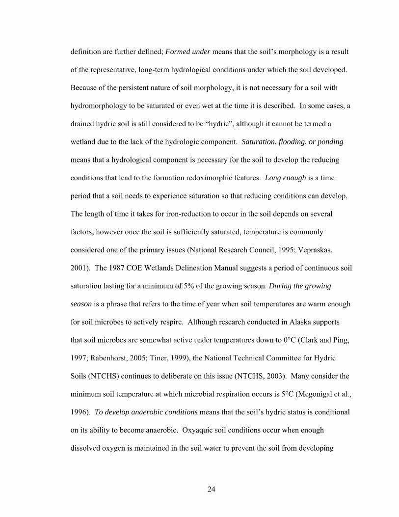
24
definition are further defined; Formed under means that the soil’s morphology is a result
of the representative, long-term hydrological conditions under which the soil developed.
Because of the persistent nature of soil morphology, it is not necessary for a soil with
hydromorphology to be saturated or even wet at the time it is described. In some cases, a
drained hydric soil is still considered to be “hydric”, although it cannot be termed a
wetland due to the lack of the hydrologic component. Saturation, flooding, or ponding
means that a hydrological component is necessary for the soil to develop the reducing
conditions that lead to the formation redoximorphic features. Long enough is a time
period that a soil needs to experience saturation so that reducing conditions can develop.
The length of time it takes for iron-reduction to occur in the soil depends on several
factors; however once the soil is sufficiently saturated, temperature is commonly
considered one of the primary issues (National Research Council, 1995; Vepraskas,
2001). The 1987 COE Wetlands Delineation Manual suggests a period of continuous soil
saturation lasting for a minimum of 5% of the growing season. During the growing
season is a phrase that refers to the time of year when soil temperatures are warm enough
for soil microbes to actively respire. Although research conducted in Alaska supports
that soil microbes are somewhat active under temperatures down to 0°C (Clark and Ping,
1997; Rabenhorst, 2005; Tiner, 1999), the National Technical Committee for Hydric
Soils (NTCHS) continues to deliberate on this issue (NTCHS, 2003). Many consider the
minimum soil temperature at which microbial respiration occurs is 5°C (Megonigal et al.,
1996). To develop anaerobic conditions means that the soil’s hydric status is conditional
on its ability to become anaerobic. Oxyaquic soil conditions occur when enough
dissolved oxygen is maintained in the soil water to prevent the soil from developing

25
anaerobic conditions. Under these oxyaquic conditions, a hydric soil cannot develop
(Vepraskas and Sprecher, 1997; Vepraskas and Faulkner, 2001). In the upper part
typically refers to the top 30 cm of the mineral material that has a texture of loamy fine
sand (or finer), and for soils with coarser textures, it refers to the upper 15 cm (NRCS,
2006)).
Characteristic morphological features of a hydric soil include concentrations and
depletions of iron, a reduced or depleted soil matrix, accumulations of organic matter on
the soil surface, and organic staining/streaking of the matrix (Mitsch and Gosselink,
2000; National Research Council (NRC), 1995; Vepraskas, 1992; Vepraskas, 2001). The
degree to which each of these features is expressed depends directly on how long the soil
is saturated and reduced (Rabenhorst, 2004).
The ability to recognize a soil as being “hydric” relies heavily on the
identification of specific morphological features that are directly related to the degree of
saturation and reducing conditions that occur in the soil. Field Indicators of Hydric Soils
(FI) were developed by The National Technical Committee for Hydric Soils (NTCHS) to
help positively identify a hydric soil. The presence of a FI is considered “proof-positive”
evidence of the soil having undergone simultaneous saturation and reduction, thereby
meeting the definition of a hydric soil (Federal Register, 1994).
All soils that are hydric may not necessarily have an Indicator. Some wetlands
that qualify by means of the hydrologic (saturated and reducing) and vegetative
components can have hydric soils that lack an approved indicator. A standard for
identifying these hydric soils was developed by the National Technical Committee for
Hydric Soils (NTCHS). This Technical Standard (TS) is based on several criteria

26
involving collecting quantitative field data, including water table data and either redox
potential data or the use of alpha-alpha Dipyridyl dye, or the use of IRIS tubes
(Castenson and Rabenhorst, 2006) (NTCHS, 2000). The TS is used in-lieu of a FI or
when evaluating a new FI. The shortcoming of using the TS as a means of determining
the hydric status of a soil is the time-investment. However, when investigating
“problematic” wet soils that are considered hydric, yet lacking a currently accepted FI,
invoking the TS is necessary.
In some cases, when delineating wetlands, the hydrologic and vegetative
components may be identifiable, however the area may not qualify if the hydric soil
component is lacking. In these cases, the soils may be considered problematic hydric
soils. The primary difficulty in identifying problematic hydric soils is that they do not
meet any of the currently accepted FI. Just because a soil does not meet any of the
current FI, however, does not mean that the soil is not hydric. Further investigation
utilizing the TS can resolve the status of questionable hydric soils. Problematic hydric
soils include some soils that formed from parent material which proved resistant to
developing redox features under reducing conditions. Examples are the soils that formed
in Triassic (“Red Parent Material”) and Permian (“Delta Ochric”) red bed materials
(Rabenhorst and Parikh, 2000; Elless, 1992; Elless et al., 1996; Faulkner et al., 1991).
Other problematic hydric soils are young soils or soils forming on active flood plains
(Castenson, 2004; Lindbo, 1997), soils with dark parent material such as Mollisols (Bell
and Richardson, 1997) and Vertisols (Jacob et al., 1997)), and sandy soils (Kuehl et al.,
1997).

27
3) Soil Water Tables and Redox Data in ABLS Soils
INTRODUCTION
This chapter addresses the relationship between soil saturation and the length of
time that is needed to develop reducing conditions strong enough to mobilize iron in
ABLS-soils.
Oxidation-reduction (redox) measurements are made in soils to theoretically determine
when redox sensitive chemical species would be stable in a soil environment (Austin and
Huddleston, 1999; James and Bartlett, 2000; Rowell, 1981). A voltage measurement is
made when a completed circuit is created by a platinum-tipped electrode, a calomel
reference electrode, and a voltmeter (Bohn, 1971; Vepraskas and Faulkner, 2001).
Potentials developed between electrodes inserted into the soil are measured in millivolts
(mV); relatively positive values infer more oxidizing conditions while relatively negative
values suggest more reducing conditions (Cogger et al., 1992; Faulkner et al., 1989).
In most seasonally saturated wetland soils, water tables rise close to (or even
above) the surface during the wet season and fall during drier (higher evapotranspiration
rates) times of the year (Mitsch and Gosselink, 2000). Elevated water tables physically
exclude air that once filled pore spaces in the soil. Under saturated conditions, oxygen-
diffusion into the soil is reduced by a factor of 104 (Craft, 2001; Ponnamperuma, 1972).
Residual oxygen in this saturated environment is quickly consumed by the remaining

28
respiring aerobic microbes (National Research Council (NRC), 1995). The oxidation of
soil organic matter (SOM) continues by anaerobic respiration with the reduction of other
chemical species in place of oxygen. Common soil minerals acting as electron sinks in
this process include manganese and iron oxides. Once reduced, these become soluble and
are able to move through the soil (Vepraskas, 1992). Warmer temperatures and greater
amounts of SOM accelerate microbial activities and result in lower redox potentials
occurring in shorter periods of time. Cooler temperatures tend to slow down microbial
respiration (Vaughan, 2008). Some have suggested that soil microbial activity ceases at
biological zero (5°C) (Vepraskas, 2001). Microbial respiration may continue at
temperatures below 5°C, although at a slower rate (Clark and Ping, 1997; Gregorich and
Janzen, 2000; Tiner, 1993). In some special cases, some soils that are saturated may be
recharged continuously by oxygenated water (oxyaquic conditions) and will not become
anaerobic and therefore not exhibit low redox potentials (Vepraskas and Sprecher, 1997;
Vepraskas and Faulkner, 2001). The degree to which each of these individual factors is
expressed greatly affects how strongly reduced a saturated soil may become.
The objectives of this study were: 1) to document water tables and redox
potentials in selected hydric soil landscapes, 2) to monitor the length of time required to
develop anaerobic conditions in saturated soils, and 3) to evaluate the impact of soil
temperature on the development of anaerobic conditions in saturated ABLS-soils.

29
MATERIALS AND METHODS
Field Methodology
Site Locations
Four study sites were chosen as part of a larger effort to examine typical soil-
landscape settings where the ABLS problem condition exists. At each of the four sites, a
three-point transect was identified that spanned a range of conditions (based on prior
observations) from more poorly drained soils (probably hydric) to better drained soils
(probably non-hydric), including an intermediate transitional site that was generally
thought to be a typical ABLS hydric soil. Sites were selected to ensure that human
impacts on hydrology and drainage were minimal, and that access to the sites was limited
to minimize the potential for vandalism. Sites were located on the Delmarva Peninsula
(Fig. 3-1), with three in Maryland and one in Delaware. The Maryland sites were at the
Blackwater National Wildlife Refuge in Dorchester County, at the Isle of Wight Wildlife
Management Area in Worcester County, and at the Eastern Neck Island National Wildlife
Refuge in Kent County. The Delaware site was located at the Ted Harvey Wildlife Area
in Kent County.

30
Figure 3-1: Approximate locations of the four ABLS research sites on the Delmarva Peninsula. (Source:http://www.cbf.org/images/content/pagebuilder/118028.gif).
Water Tables
Water tables were monitored using automated recording wells (RDS WL80)
installed to an approximate depth of 1.5 m and programmed to record data twice daily.
At each of the four study sites, these wells were located at the three points representing
the lower, middle, and upper portions of the transect (Sprecher, 2008). Data were
downloaded periodically using a hand-held Hewlett-Packard calculator with an infrared

31
interface. Water levels in open wells were observed occasionally to verify the proper
operation of the recording wells.
Oxidation-Reduction Potentials and pH
At each of the transect points and within one meter of the monitoring wells, redox
potentials were measured using six replicate platinum-tipped electrodes, calomel
reference electrodes, and voltmeters. The Pt electrodes were inserted into the soil at
depths of 10, 20, 30, 40, and 50 cm and voltages recorded after permitting some
reasonable time for equilibration (typically, 2-5 minutes). During the wet season
(approximately November through April) redox potentials were measured bi-weekly.
They were measured at monthly intervals during the drier times of the year. pH was
measured on the same occasions and at the same depths as redox potential. To measure
pH, a 16 mm soil corer was used to extract a small soil sample which was made into a 1:1
slurry with de-ionized water. Measurements were taken in the field with a portable pH
meter.
Soil Temperatures
Soil temperatures were recorded at the research sites using automated data
loggers. At each of the four sites, three recorders were buried adjacent to the middle
well, one each at 10, 30, and 50 cm depth. Loggers were programmed to take
measurements every four hours. Data were downloaded at the end of three years using an
optical interface and desktop computer.

32
Soil Description and Sampling
Adjacent to each well, a pit was dug by hand to one to two meters. Soils were
described in detail using protocols of the National Cooperative Soil Survey (NCSS) (Soil
Survey Staff, 1993; Schoeneberger, 2002) and then sampled by horizon. At the base of
some pits, if conditions permitted, a hand auger was used to further describe soils to
depths that ranged from 129 cm to 335 cm. Soils were subsequently classified (Soil
Survey Staff, 2006)
Laboratory Methodology
Organic carbon content was determined on duplicate, ground soil samples from
each pedogenic horizon. Analyses were run by dry combustion (950°C) using a LECO
CNH analyzer (Nelson and Sommers, 1982; Tabatabai and Bremner, 1991).
RESULTS AND DISCUSSION
Water Tables
Water table data collected at all four research sites for a period of approximately
three years, from February, 2001 through February, 2004 are shown in figures 3-2
through 3-5. Within this period, two complete wet (November - April) and dry (May -
October) seasonal cycles were captured for analysis.

33
Mar-01 Jun-01 Sep-01 Dec-01 Mar-02 Jun-02 Sep-02 Dec-02 Mar-03 Jun-03 Sep-03 Dec-03 Mar-04
-2
-1.75
-1.5
-1.25
-1
-0.75
-0.5
-0.25
0
0.25
0.5
0.75
Dep
th (m
)Upper Well Middle Well Lower Well
Water Table HeightsBlackwater NWR, Dorchester Co, MD
Figure 3-2: Complete water table data (Feb 2001 – Feb 2004). Lower, middle, and upper well positions at Blackwater are represented by blue, green, and red lines, respectively.

34
Mar-01 Jun-01 Sep-01 Dec-01 Mar-02 Jun-02 Sep-02 Dec-02 Mar-03 Jun-03 Sep-03 Dec-03 Mar-04
-1.75
-1.5
-1.25
-1
-0.75
-0.5
-0.25
0
0.25
0.5D
epth
(m)
Upper Well Middle Well Lower Well
Water Tables HeightsIsle of Wight WMA, Worcester Co, MD
Figure 3-3: Complete water table data (Feb 2001 – Feb 2004). Lower, middle, and upper well positions at Isle of Wight are represented by blue, green, and red lines, respectively.

35
Mar-01 Jun-01 Sep-01 Dec-01 Mar-02 Jun-02 Sep-02 Dec-02 Mar-03 Jun-03 Sep-03 Dec-03 Mar-04
-2
-1.75
-1.5
-1.25
-1
-0.75
-0.5
-0.25
0
0.25
0.5
0.75
1D
epth
(m)
Upper Well Middle Well Lower Well
Water Table HeightsEastern Neck NWR, Kent Co, MD
Figure 3-4: Complete water table data (Feb 2001 – Feb 2004). Lower, middle, and upper well positions at Eastern Neck Island are represented by blue, green, and red lines, respectively.

36
Mar-01Jun-01
Sep-01Dec-01
Mar-02Jun-02
Sep-02Dec-02
Mar-03Jun-03
Sep-03Dec-03
Mar-04-1.75
-1.5
-1.25
-1
-0.75
-0.5
-0.25
0
0.25
0.5D
epth
(m)
Upper Well Mid Well Lower Well
Water Table HeightsTed Harvey, Kent County, DE
Figure 3-5: Complete water table data (Feb 2001 – Feb 2004). Lower, middle, and upper well positions at Ted Harvey are represented by blue, green, and red lines, respectively.

37
Not surprisingly, soils on the “upper” end of the transects had water tables that
were generally deeper than those at the lower of each end of the transect. Soils at the
midpoint of each transect commonly showed intermediate water table levels. Soils on the
transects were continuously saturated to within 30 cm of the soil surface for periods
ranging from 204 days (Ted Harvey site) to 361 days (Blackwater site) on the “lower”
end of transects and from 62 days (Ted Harvey site) to 361 days (Blackwater site) on the
“upper” end of transects. For the period of study (two hydrologic years: February 2001 –
February 2003), the cumulative time that a soil was saturated was calculated as a
percentage of the year; Figures 3-6 and 3-7 show average percentages of the year that
each soil was saturated to 30 cm and at the surface, respectively. Proximity of water
tables relative to the soil surface differed somewhat from site to sites. Soils at the
Blackwater site were saturated much more often and for longer periods compared to
those at the other sites. Water tables at the remaining three sites were more similar to one
another, although the Ted Harvey site stands out as being less wet than the Eastern Neck
and Isle of Wight sites (Fig. 3-7).

38
0
10
20
30
40
50
60
70
80
90
100
Blackwater Isle of Wight Eastern Neck Island Ted Harvey
Sat
urat
ion
(%)
lower middle upper
Figure 3-6: Average percentage of the year that the ground water levels reached 30 cm in the lower, middle, and upper soils at each of the four research sites (February 2001-February 2004).
0
10
20
30
40
50
60
70
80
90
100
Blackwater Isle of Wight Eastern Neck Island Ted Harvey
Sat
urat
ion
(%)
Lower middle upper Figure 3-7: Average percentage of the year that the ground water levels reached the soil surface in the lower, middle, and upper soils at each of the four research sites (February 2001- February 2004).

39
Redox Potential and pH
The reduction of iron from its insoluble, oxidized form (Fe(III)), to its more-
soluble, reduced state (Fe(II)) is dependent on both the Eh and pH of the soil. Attempts
to predict the reduction of iron oxides in wet soils have been made by using
thermodynamic data and plotting mineral stability fields on an Eh/pH diagram
(Karathanasis, 2002). Taking a more empirical approach, the National Technical
Committee for Hydric Soils (NTCHS) developed a Technical Standard (TS) for hydric
soils that includes criteria for documenting reduced soil conditions. Measured data are
plotted on an Eh/pH diagram, where the equation Eh = 595 - 60 (pH) defines the
threshold between oxidizing and reducing conditions (Fig. 3-8). When the measured Eh
and pH plot above the line, the soil is considered oxidized and when the data plot below
the line, the soil environment is considered reducing. Therefore, both Eh and pH were
measured. Soil pH was observed to change only gradually over time. Therefore, some
missing pH data were interpolated from measurements taken on earlier and later dates.

40
-600
-400
-200
0
200
400
600
800
3 3.5 4 4.5 5 5.5 6 6.5 7
pH
Eh (m
V)
TSGoethiteHematite
Reducing Conditions
Oxidizing Conditions
Figure 3-8: Eh/pH stability diagram showing lines representing boundaries between reducing and oxidizing conditions in the soil (relative to criteria set forth by the National Technical Committee for Hydric Soils (NTCHS, 2000)). The orange and red lines represent the stability fields of the minerals goethite (FeOOH) and hematite (Fe2O3), respectively; and the black line represents the Technical Standard (TS). Goethite and hematite lines were calculated based on Fe-activity of 10-6M.
Lower Landscape Positions
Redox potentials measured in soils at the lower (wet) end of the transects were
generally lower, and reducing conditions lasted longer than in soils at the “middle” and
“upper” sections of the transect. Redox potentials measured at 20-cm depths and below
at the Blackwater site remained below the Technical Standard line (indicating reducing
conditions) for essentially the entire time that Eh was recorded (Feb. 2001 – Aug. 2003).
Although this site was saturated to the surface for most of the year, redox potentials at 10
cm sometimes were oxidizing, perhaps due to movement of oxygenated rainwater into
the upper part of the soil. Contributing to this was a thick, highly porous hemi-to-fibric
surface horizon which physically made it more difficult to obtain accurate redox potential

41
measurements closer to the surface (0-10 cm). At the Isle of Wight site, reducing
conditions (based on the Technical Standard) persisted at depths of 20 cm and below for
periods ranging from 1 to 10 consecutive weeks and at the 30 cm depth from 3.5 to 10
consecutive weeks. The Eastern Neck Island site showed reducing conditions at the 20-
cm depth from 1 to 20 consecutive weeks and at the 30-cm depth from 1 to 23
consecutive weeks; while at the Ted Harvey site, reducing conditions occurred regularly
only at depths of 30 cm and below for periods ranging from 1 to almost 10 consecutive
weeks (Figs. 3-9a, b, c, and d).
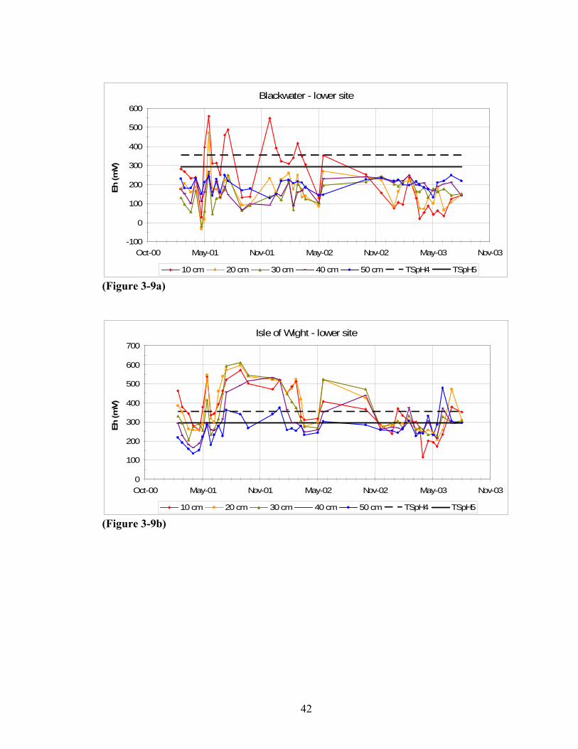
42
Blackwater - lower site
-100
0
100
200
300
400
500
600
Oct-00 May-01 Nov-01 May-02 Nov-02 May-03 Nov-03
Eh (m
V)
10 cm 20 cm 30 cm 40 cm 50 cm TSpH4 TSpH5 (Figure 3-9a)
Isle of Wight - lower site
0
100
200
300
400
500
600
700
Oct-00 May-01 Nov-01 May-02 Nov-02 May-03 Nov-03
Eh (m
V)
10 cm 20 cm 30 cm 40 cm 50 cm TSpH4 TSpH5 (Figure 3-9b)

43
Eastern Neck Island - lower site
0
100
200
300
400
500
600
700
Oct-00 May-01 Nov-01 May-02 Nov-02 May-03 Nov-03
Eh (m
V)
10 cm 20 cm 30 cm 40 cm 50 cm TSpH4 TSpH5 (Figure 3-9c)
Ted Harvey - lower site
0
100
200
300
400
500
600
700
Oct-00 May-01 Nov-01 May-02 Nov-02 May-03 Nov-03
Eh (m
V)
10 cm 20 cm 30 cm 40 cm 50 cm TSpH4 TSpH5
(Figure 3-9d)
Figure 3-9 a-d: Redox potentials measured in soils at the lower transect points. Data are means of six replicate measurements at 10, 20, 30, 40, and 50 cm depths below the soil surface. The two black, horizontal lines represent a range within which iron becomes reduced based on the Technical Standard at pH 4 (upper horizontal line) and at pH 5 (lower horizontal line), as the pH values in the soils generally ranged between 4 and 5.

44
Middle Landscape Positions
Relative to soils at the low end, soils at the middle positions at each site generally
showed shorter periods of reducing conditions, and the reducing conditions generally
were at greater depths in the soil profile. Only the Blackwater site showed little
difference in redox potentials between the lower and middle positions of the transect,
where reducing conditions persisted for approximately 44 weeks to within 20 cm of the
surface, and for nearly 102 weeks at the 30-cm depth and below. At the Isle of Wight
site, both redox and water table data indicated that the middle position is actually slightly
drier, than the upper position on that transect. Reducing conditions were observed at the
depth of 20 cm only for 4 consecutive weeks and then again on two other individual
occasions. At 30 cm, however, the period of reduction was longer, and ranged from 5 to
12 consecutive weeks. At the Eastern Neck Island site, soils at the middle point had
water tables and redox potentials much like soils at that site’s low position. At the Ted
Harvey site, soils at the mid-part only showed evidence of reducing conditions at the 20
cm depth on three, non-sequential occasions. Based on calculations using interpolated pH
data, redox potentials around 30 cm appear to fall below the Technical Standard line for
reducing conditions for approximately 11 weeks (Figs. 3-10a, b, c, and d).

45
Blackwater - middle site
-100
0
100
200
300
400
500
600
Oct-00 May-01 Nov-01 May-02 Nov-02 May-03 Nov-03
Eh (m
V)
10 cm 20 cm 30 cm 40 cm 50 cm TSpH4 TSpH5 (Figure 3-10a)
Isle of Wight - middle site
0
100
200
300
400
500
600
700
Oct-00 May-01 Nov-01 May-02 Nov-02 May-03 Nov-03
Eh (m
V)
10 cm 20 cm 30 cm 40 cm 50 cm TSpH4 TSpH5 (Figure 3-10b)

46
Eastern Neck Island - middle site
0
100
200
300
400
500
600
700
Oct-00 May-01 Nov-01 May-02 Nov-02 May-03 Nov-03
Eh (m
V)
10 cm 20 cm 30 cm 40 cm 50 cm TSpH4 TSpH5 (Figure 3-10c)
Ted Harvey - middle site
0
100
200
300
400
500
600
700
Oct-00 May-01 Nov-01 May-02 Nov-02 May-03 Nov-03
Eh (m
V)
10 cm 20 cm 30 cm 40 cm 50 cm TSpH4 TSpH5 (Figure 3-10d) Figure 3-10 a-d: Redox potentials measured in soils at the mid-points of the transect. Data are means of six replicate measurements at 10, 20, 30, 40, and 50 cm depths below the soil surface. The two black horizontal lines represent a range within which iron reduces based on the Technical Standard at pH 4 (upper horizontal line) and at pH 5 (lower horizontal line), as the pH values in the soils ranged from 4 to 5.

47
Upper Landscape Positions
In general, soils located toward the upper end of the transect generally did not
experience the wetness conditions that are required to induce iron reduction in the upper
part of the soil. Although conditions for iron reduction appeared to be present at most
sites at depths of 40 and 50 cm, the Blackwater site was the exception with soils
experiencing saturation close to the soil surface throughout the year; even at the upper
position. This was partly due to the site’s low elevation and the minimal topographic
variation across the transect. For these reasons, reducing conditions were observed at the
Blackwater site for extended periods ranging from 4 to 27 consecutive weeks at the 20-
cm depth, and from 4 to 44 consecutive weeks at the 30-cm depth. Redox measurements
at 10 cm showed that the soil at this depth occasionally became oxidized. At the upper
end of the transect of the Isle of Wight site, soils were slightly wetter than those at the
middle position; redox potentials therefore paralleled these conditions accordingly.
Measurements at 20 cm indicated reducing conditions for up to 18 weeks, while at the
30-cm depth, periods of reduction occurred more frequently and lasted longer (up to 23
weeks). The Eastern Neck Island site showed trends that were more as expected.
Reducing conditions were documented at 30-cm depths occasionally only during the wet
seasons, and for a four-consecutive-week period only once. The soils at the upper end of
the transect at Ted Harvey site proved to be the driest of all sites. Reducing conditions at
30 cm were not observed on only three non-consecutive visits (Figs. 3-11a, b, c, and d).

48
Blackwater - upper site
-100
0
100
200
300
400
500
600
Oct-00 May-01 Nov-01 May-02 Nov-02 May-03 Nov-03
Eh (m
V)
10 cm 20 cm 30 cm 40 cm 50 cm TSpH4 TSpH5
(Figure 3-11a)
Isle of Wight - upper site
0
100
200
300
400
500
600
700
Oct-00 May-01 Nov-01 May-02 Nov-02 May-03 Nov-03
Eh (m
V)
10 cm 20 cm 30 cm 40 cm 50 cm TSpH4 TSpH5 (Figure 3-11b)

49
Eastern Neck Island - upper site
0
100
200
300
400
500
600
700
Oct-00 May-01 Nov-01 May-02 Nov-02 May-03 Nov-03
Eh (m
V)
10 cm 20 cm 30 cm 40 cm 50 cm TSpH4 TSpH5
(Figure 3-11c)
Ted Harvey - upper site
0
100
200
300
400
500
600
700
Oct-00 May-01 Nov-01 May-02 Nov-02 May-03 Nov-03
Eh (m
V)
10 cm 20 cm 30 cm 40 cm 50 cm TSpH4 TSpH5
(Figure 3-11d)
Figure 3-11 a-d: Redox potentials measured in soils at the upper points of the transect. Data are means of six replicate measurements at 10, 20, 30, 40, and 50 cm depths below the soil surface. The two black horizontal lines represent a range within which iron reduces based on the Technical Standard at pH 4 (upper horizontal line) and at pH 5 (lower horizontal line), as the pH values in the soils ranged from 4 to 5.

50
Soil Temperatures
Distinct, seasonal temperature fluctuations in the soil were evident. Figure 3-12
illustrates soil temperature data at 30 cm from three out of the four research sites; data
loggers buried at the Eastern Neck Island site were not recovered.
Comparing temperatures at soil depths of 10 cm, 30 cm, and 50 cm at a single
site (Isle of Wight), it was apparent that seasonal temperature fluctuations were
increasingly moderated with soil-depth (Fig. 3-13).
Because soil temperatures were relatively similar from the three research sites,
data were averaged at the three depths to represent soil temperature data for the Eastern
Neck Island site. Furthermore, because redox data, pH data, and water table data were
gathered at 10-, 20-, 30-, 40-, and 50-cm depths, it was desirable to also have temperature
data at all depths. Therefore, soil temperatures at depths at 20 cm and 40 cm were
determined by interpolation.
Each of the four sites showed noticeable temperature differences at 10 cm.
Considering the number of days that soil temperatures dropped below 5°C, as well as the
lowest temperatures that were logged at the 10-cm depth, Ted Harvey was the coolest of
the four sites. Oppositely, the soils at the Blackwater site appeared to be warmest,
possibly due to the insulating effects of the thick, organic surface horizon covering the
soil surface or to the extreme wetness they experience. The Isle of Wight site showed
soil temperatures intermediate to Ted Harvey and Blackwater.
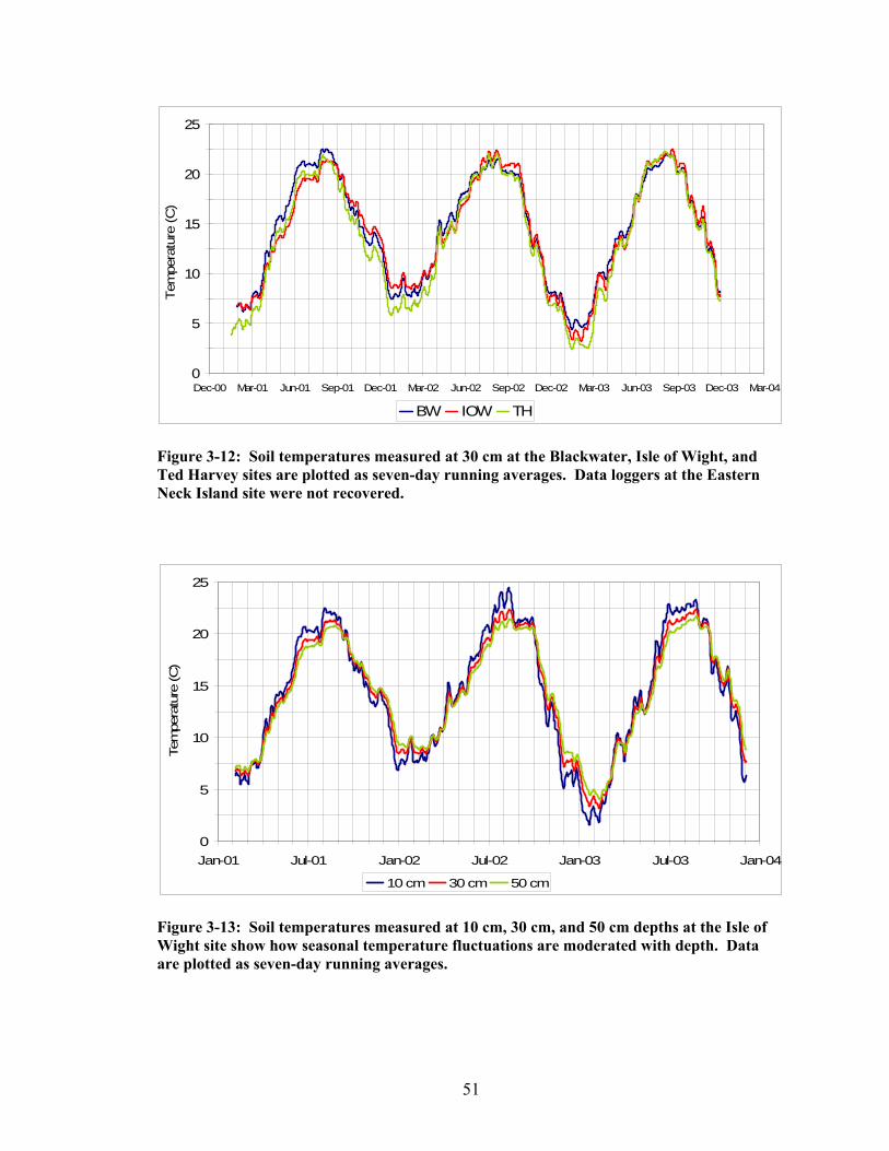
51
0
5
10
15
20
25
Dec-00 Mar-01 Jun-01 Sep-01 Dec-01 Mar-02 Jun-02 Sep-02 Dec-02 Mar-03 Jun-03 Sep-03 Dec-03 Mar-04
Tem
pera
ture
(C)
BW IOW TH Figure 3-12: Soil temperatures measured at 30 cm at the Blackwater, Isle of Wight, and Ted Harvey sites are plotted as seven-day running averages. Data loggers at the Eastern Neck Island site were not recovered.
0
5
10
15
20
25
Jan-01 Jul-01 Jan-02 Jul-02 Jan-03 Jul-03 Jan-04
Tem
pera
ture
(C)
10 cm 30 cm 50 cm Figure 3-13: Soil temperatures measured at 10 cm, 30 cm, and 50 cm depths at the Isle of Wight site show how seasonal temperature fluctuations are moderated with depth. Data are plotted as seven-day running averages.

52
Soil Redox Properties vs. Length of Saturation
Redox potentials are affected by a number of factors inherent to the soil
environment. Of these factors, saturation due to elevated water tables is one of the main
driving forces behind the development of anaerobic conditions in the soil. We know that,
generally, soils first become saturated, and then after some period of time, they become
reducing. The length of time required for saturated soils to become reducing has not been
thoroughly investigated, however has been documented (Vaughan, 2009). We know
from experience that it is a much simpler and less-expensive process to measure soil
water tables than it is to measure soil redox potentials. Therefore, it would be helpful if
we could describe the relationship between saturation and the onset of reducing
conditions. By developing a model that describes the relationship between soil saturation
and the time it takes for soils to develop reducing conditions, available water table data
might then be used to infer a soil’s redox status.
In order to limit the variability in the soil properties that might affect the
development of reducing conditions, certain portions of the soil data set were removed
based on the following reasons:
1. Soil horizons that were saturated for extremely long periods of time (>200
days) were usually continuously and strongly reduced, such as the soils at the Blackwater
site. Under these conditions, those horizons did not adequately transition between
oxidizing and reducing conditions, and therefore would not contribute any significant
information to our model.
2. The upper 10 cm of pedons had highly variable organic carbon (OC) contents
that ranged from 24.5 g/kg to 106.5 g/kg, which also affected the physical properties of

53
these horizons (high porosity) in some soils (Nelson and Sommers, 1982). This led to
difficulties in obtaining reliable Eh measurements and therefore these horizons were
excluded from analyses (Tab. 3-1).
3. The redox data from the 50-cm depth at the upper site at the Isle of Wight were
not included because a coarse sand lens was encountered precisely at that depth causing
the Eh data to be abnormally high there.
Table 3-1: Organic carbon content (g/kg) of ABLS-soils in horizons (excluding surface horizons) to approximately 50 cm (depths based on horizon breaks).
Landscape Position Depth Carbon Content Site Lower cm g/kg Blackwater 16-24 5.04 Blackwater 25-39 4.09 Blackwater 39-53 4.52 Isle of Wight 27-45 2.60 Isle of Wight 45-61 2.75 Eastern Neck Island 15-32 2.55 Eastern Neck Island 32-42 2.54 Eastern Neck Island 42-62 1.75 Ted Harvey 14-26 22.64 Ted Harvey 26-39 6.43 Ted Harvey 39-63 3.82 Middle Blackwater 22-51 3.16 Isle of Wight 20-33 3.81 Isle of Wight 33-49 3.65 Eastern Neck Island 15-28 3.25 Eastern Neck Island 28-45 1.96 Eastern Neck Island 45-69 1.62 Ted Harvey 14-26 12.47 Ted Harvey 26-40 3.75 Ted Harvey 40-68 3.44 Upper Blackwater 16-33 4.51 Blackwater 33-63 3.32 Isle of Wight 18-31 2.17 Isle of Wight 31-55 1.24 Eastern Neck Island 14-38 2.91 Eastern Neck Island 38-56 1.63 Ted Harvey 20-33 6.41 Ted Harvey 33-52 5.42

54
Using this modified data set, the soil Eh and pH were compared with the water
table records at the same depth where Eh was measured. On each day when Eh was
measured, it was determined whether or not the soil was saturated, and if so, for how long
it had been saturated. These data are plotted in figure 3-14. There is a great deal of
natural variability in this system, and that there are factors other than the length of
saturation that are affecting soil redox potentials. Nevertheless, a best-fit line can be
placed in the data that shows that approximately 49% of the variability can be accounted
for by the length of time the soil was saturated.
The soil pH at these sites generally ranged between values of 4 and 5. Based on
the equation for the TS-line (Fig. 3-4), the Eh corresponding to pH values of 4 and 5 are
355 mV and 295 mV, respectively. The best-fit line calculated for the data intersects
these values (355 mV and 295 mV) at 20 days and at 63 days, respectively, suggesting
that in general, these soils become reducing sometime between 20 and 63 days of
continuous saturation.
Relating measured redox potentials to a static pH-range likely obscures our
understanding. Therefore the data set was reevaluated in a way that takes all pH values
into account, resulting in more focused results. Each data point was individually
recalculated using field pH measurements, where Eh and pH (measured at each depth and
at each site) were compared to the TS-line. The difference in mV between measured
field Eh values and the Eh corresponding to the TS at the pH in the soil was then plotted
as “Eh relative to the TS” (Eh=0=TS). These data are shown in figure 3-15. This
approach eliminated variability associated with soil pH and resulted in a slightly better

55
fit, with r2 = 0.54 (Fig. 3-15). This best-fit line intersects the x-axis (TS-line) at
approximately 43 days, indicating that after approximately 43 days of continuous
saturation, soils became reducing as defined by the TS.

56
y = -52.844Ln(x) + 513.68R2 = 0.4932
-400-300-200-100
0100200300400500600700800
0 10 20 30 40 50 60 70 80 90 100 110 120 130 140 150 160 170 180 190 200
Days Continuous Saturation
Eh
(mV)
data TSpH4 TSpH5 20 days 63 days Log. (data)
63 days20 days
Figure 3-14: Graph showing soil environment reaching the Technical Standard (qualifying as a “hydric soil”) under continually saturated conditions between soil pH ranges of 4 (dotted horizontal black line) and 5 (solid horizontal black line). Where the least-squares (red) line (best-fit logarithmic regression of the data) crosses the TSpH4 line, soils qualify as “hydric” after approximately 20 days of continuous saturation and where the yellow line crosses the TSpH5 line, soils qualify as hydric after approximately 63 days of continuous saturation. All soil temperatures are included in this data set.
57
y = -48.55Ln(x) + 182.95R2 = 0.5394
-400-300-200-100
0100200300400500600700800
0 10 20 30 40 50 60 70 80 90 100 110 120 130 140 150 160 170 180 190 200
Days Continuous Saturation
Eh
Rel
ativ
e to
the
TS (m
V)
data TS line 43 days Log. (data)
43 days
Figure 3-15: Graph showing measured redox/pH data relative to the Technical Standard. A least squares (red) line (best-fit logarithmic regression of the data) follows the general trend of the data. The soil environment at or below the TS-line is assumed to qualify as “hydric” under continually saturated conditions. Taking all temperature data into account, soils reach “hydric” status where the yellow line crosses the TS-line (after approximately 43 days of continuous saturation).

58
Temperature Effects on Redox Potentials
Although soil saturation is considered one of the primary driving forces behind
the onset of reducing conditions, we know that microbial respiration is also affected by
soil temperature. Soils usually experience the coldest temperatures of the year during
times when water tables are closest to the surface. Although fully saturated, soil
microbial processes could be expected to be very slow during these times. Therefore, the
redox potentials plotted relative to the Technical Standard in figure 3-15 were
subsequently separated into temperature groups.
Fourteen-day running averages for temperature (calculated for the particular depth
at which the Eh measurements were taken) were used to minimize the effect of short-
termed temperature fluctuations. Redox potentials were assembled into 5°C temperature
ranges (<5.0, 5.0-9.9, 10.0-14.9, and >15.0) and plotted against days of continuous
saturation (Fig. 3-16). Data included in each of these temperature ranges reflected a
relatively even distribution of data; the concept of biological zero (5°C) was taken into
consideration when selecting the ranges.
A least-squares best-fit line was calculated and plotted for the data in each
temperature range. These data are shown in figure 3-16. The point where each of the
lines crosses the TS-line (x-intercept) represents the approximate number of days the
soils were continuously saturated when the soils developed reducing conditions (within
that particular temperature range).
It is evident in figure 3-16, that as the temperature of the saturated soil increases,
it takes less time for reducing conditions to develop. The x-intercepts for the four best-fit
lines were plotted in figure 3-17 to show how differences in soil temperature can affect

59
redox processes. A best-fit power-function was fit to the points and demonstrates the
relationship between length of saturation, soil temperature, and the onset of reducing
conditions. The slope of the curve in figure 3-17 illustrates that as temperatures drop
from 10°C to 5°C, the curve becomes much steeper indicating that microbial activity
slows dramatically. Conversely, at temperatures above 10°C, the curve begins to level
out, indicating at these temperatures microbes are active and are less affected by soil
temperatures.
It is important to note, however, that this data set is comprised wholly of field-
data and therefore includes a great deal of variability as is usually associated with such
research practices. Fine-scale variations in organic matter content, the presence of plant
roots, the amount of active C contributed seasonally during plant senescence, and soil
macro-pores are among the factors, likely contributed to the variability.

60
R2 = 0.2626
R2 = 0.5541
R2 = 0.4761
R2 = 0.6415
-350
-250
-150
-50
50
150
250
350
450
0 10 20 30 40 50 60 70 80 90 100 110 120 130 140 150 160 170 180 190 200
Continuous Saturation (days)
Eh
rela
tive
to th
e TS
<5.0C 5.0-9.9C 10.0-14.9C >15.0C TS Line Log. (<5.0C) Log. (5.0-9.9C) Log. (10.0-14.9C) Log. (>15.0C)
Figure 3-16: Graph showing soil temperatures grouped into 5°C ranges and their effects on redox rates in the soil. Where colored lines (best-fit logarithmic regression of the data) cross the Technical Standard (horizontal black line) it is assumed that the soil has reached a reduced state (according to the Technical Standard) after x-days of continuous saturation.

61
0
20
40
60
80
100
120
140
0 1 2 3 4 5 6 7 8 9 10 11 12 13 14 15 16 17 18 19 20 21 22 23 24 25
Temperature (C)
Con
tinuo
us S
atur
atio
n (d
ays)
avg. temp. wthin range temperature range Power (avg. temp. wthin range)
123 days
57 days
35 days
18 days
Figure 3-17: Graph shows the x-intercepts of least-squares best-fit (power regression of the data) temperature range lines from Figure 3-16. Data follow a best-fit power function. Horizontal red lines represent temperature ranges with black +/- standard error bars (of means).

62
CONCLUSIONS
Soils on the Delmarva Peninsula, representing the ABLS phenomenon, did
experience reducing conditions after being saturated for extended periods of time. An
initial assessment comparing Eh and the period of soil saturation indicated that the soil
became reducing with respect to iron somewhere between 20 and 63 days. This
assessment was refined by including measured soil pH values into the calculations and
comparing each data point to the TS-line [Eh = 595-60(pH)].
Using this approach, we found that ABLS-soils became reducing (relative to the TS) after
approximately 43 days of saturation.
Because soil temperature affects the rates of microbial activity, the calculations
were further refined by separating the data according to measured soil temperature.
These data showed that, although reducing conditions will develop under cold conditions,
the required period of saturation is longer when soil temperatures are colder. At 4°C,
soils needed to be saturated for approximately 123 days in order to become reducing,
whereas at 19°C soils only needed to be saturated for approximately 18 days to become
reducing.
In light of these conclusions, we can reject the first and second hypotheses.

63
4) Relationship between Soil Morphology and Length of Saturation
INTRODUCTION
Wetland soils that experience seasonal saturation due to fluctuating water tables
commonly undergo chemical and morphological changes (Rabenhorst, 2004). Water
tables that saturate the soil exclude soil air and dramatically decrease soil aeration. If
allowed to remain saturated for a long enough period of time when temperatures are
warm enough for microorganisms to respire, the soil environment becomes anaerobic
(Meek et al., 1968). Under these conditions, thermodynamically predicted mineral
transformations take place (James and Bartlett, 2000; Rowell, 1981). Although several
mineral species in the soil are affected, the focus of this chapter is on iron oxides. In their
oxidized state, these minerals are insoluble and act as strong soil pigmenting agents
(Bigham et al., 2002). However, if sufficiently reducing conditions in the soil persist for
long enough periods of time, ferric iron (Fe3+) is reduced to its ferrous state (Fe2+).
Ferrous iron is colorless, soluble, and highly mobile in the soil, and able to move with
soil pore water and groundwater along hydrologic flow paths.
The degree to which a soil experiences saturation and reduction is closely related
to, and expressed by, its morphology (Daniels et al., 1971; Franzmeier et al., 1983; He et
al., 2003; Jacobs et. al., 2002; Pickering and Veneman, 1984; Rabenhorst, 2004). In soils
that repeatedly experience cycles of reducing and oxidizing conditions, Fe accumulates in
some areas, forming iron “concentrations”, while leaving adjacent areas gray and
depleted of iron (iron “depletions”) (D’Amore et al., 2004; Boersma et al., 1972;
Faulkner and Patrick, 1992).
64
There have been numerous studies that relate soil morphology to the duration of
saturation and include work by Galusky et al. (1998), Jacobs et al. (2002), Morgan and
Stolt (2006), West et al. (1998), and Castenson (2004). Galusky’s PhD research
correlated precipitation data to water tables in soils on the Maryland coastal plain. The
studies conducted by Jacobs et al., Morgan and Stolt, and West et al. investigated the
relationship between soil morphology and seasonal water tables of soils on the Middle
Coastal plain in Georgia, the southern coast of Rhode Island, and in the Dougherty Plain
of southwest Georgia, respectively. In general, these studies found similar results: Fe-
concentrations developed when soils were saturated for short periods of time, usually for
between 2 and 20% of the year. Iron depletions formed as the length of saturation
increased to approximately 17 to 40% of the year; and a depleted matrix occurred when
soils were saturated for 42 to 57% of the year. Castenson’s MS thesis project reported on
soils on Mid-Atlantic piedmont floodplains and their reticence to express what was
thought of as typical hydromorphology, probably due to the young age of the parent
material in the alluvial floodplain settings. These piedmont floodplain soils needed
significantly longer saturation times to form the types and abundance of redoximorphic
features similar to those in soils in other settings.
A group of soils on the Mid Atlantic coastal plain was observed that did not
express morphological indicators considered typical for soils experiencing this same
degree of saturation and thus, in this sense, they have been referred to as “problematic”.
This group of soils has been termed “Anomalous Bright Loamy Soils” (ABLS). These
soils have been observed to occur mostly along low-lying coastal areas with a subtle,
convex shape to their landscapes, and nearly always are within 100-200 meters of the
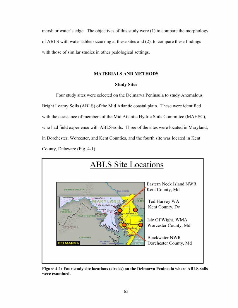
65
marsh or water’s edge. The objectives of this study were (1) to compare the morphology
of ABLS with water tables occurring at these sites and (2), to compare these findings
with those of similar studies in other pedological settings.
MATERIALS AND METHODS
Study Sites
Four study sites were selected on the Delmarva Peninsula to study Anomalous
Bright Loamy Soils (ABLS) of the Mid Atlantic coastal plain. These were identified
with the assistance of members of the Mid Atlantic Hydric Soils Committee (MAHSC),
who had field experience with ABLS-soils. Three of the sites were located in Maryland,
in Dorchester, Worcester, and Kent Counties, and the fourth site was located in Kent
County, Delaware (Fig. 4-1).
ABLS Site Locations
Eastern Neck Island NWRKent County, Md
Ted Harvey WAKent County, De
Isle Of Wight, WMAWorcester County, Md
Blackwater NWRDorchester County, Md
Figure 4-1: Four study site locations (circles) on the Delmarva Peninsula where ABLS-soils were examined.

66
Each of the sites was thought to be representative of typical soil-landscape
settings where the problem ABLS-conditions exists. Sites were selected with several
criteria in mind to ensure the success of the study. In particular, sites were selected to
ensure that present drainage and hydrological conditions had not been significantly
altered (such as by drainage structures), and also that public access to the sites was
limited to reduce possible vandalism of equipment placed at the sites. At each site, a
transect was identified along a hydrosequence where soils ranged from more poorly
drained (probably hydric) to better drained (probably not hydric) conditions.
Water Tables
Water tables were monitored using Remote Data Systems automated recording
wells (RDS, Inc., Wilmington, NC), capturing water table levels twice daily to a
maximum depth of approximately 1.5 m. At each site, three wells were installed along
the transect to confirm the presence of a hydrosequence (Sprecher, 2008). Well data
were periodically downloaded using a hand-held Hewlett-Packard calculator with
infrared interface, and then were off-loaded to a computer for processing.
Soils
Soil pits were dug by hand and described to depths ranging from 88 cm to 170
cm, depending on the depth to water table levels present at the time when soils were
described. Starting at the base of most pits, soils were further described by augering to
depths that ranged from 129 cm to 335 cm. Soil descriptions were made following
standard protocols (Soil Survey Staff, 1993), while focusing detailed attention on the

67
identification and description of redoximorphic features. The percentages of
redoximorphic features were estimated to the nearest percent by comparing with standard
reference charts.
Soil samples were collected from each horizon. In the lab, samples were air-dried
and crushed to pass through a 2-mm sieve. Samples were analyzed for particle size
(PSA) using the pipette-method (Gee and Bauder, 1986). Samples were also analyzed for
organic carbon in the mineral fraction by dry-combustion at 950°C (Nelson and
Sommers, 1982; Tabatabai and Bremner, 1991).
Precipitation
Precipitation data were initially collected for the Isle of Wight, the Eastern Neck
Island, and the Ted Harvey sites using tipping-bucket rain gauges (the Blackwater site
was not instrumented). However, technical difficulties were encountered using these
gauges including mechanical failure and animal (insect) intrusion that made it impractical
to rely solely on these data for analysis. Therefore, the data from local weather stations
positioned relatively close to each of the sites were identified and utilized for substitute
precipitation data. The weather station in Vienna, MD (Dorchester County:
latitude/longitude: 38°29'N / 75°49'W) was referenced for the Blackwater research site
(approximately 19 km (12 mi) away); the weather station at the Ocean City Airport
(Worcester County: latitude/longitude: 38°19'N / 75°07'W) located in Ocean City, MD
was referenced for the Isle of Wight research site (approximately 8 km (5 mi) away); the
weather station in Chestertown, MD (Kent County, MD: latitude/longitude: 39°13'N /
76°03'W) was referenced for the Eastern Neck Island research site (approximately 20 km

68
(12 mi) away); and the weather station in Dover, DE (Kent County, DE:
latitude/longitude: 39°16'N / 75°31'W) was referenced for the Ted Harvey research site
(approximately 7 km (4 mi) away).
RESULTS AND DISCUSSION
Soils
Organic carbon content of ABLS-soils was generally found to be within the range
of Coastal Plain soils with similar drainage found on the Delmarva Peninsula (Figs. 4-2a,
b, c, and d) (Foss et al., 1969, Soil Survey Staff, 2008). Maximum carbon content in
these soils occurred at the surface, in O- and A-horizons. Below these horizons, the
amount of carbon tapered off quickly, generally to less than approximately 5g/kg, within
20 cm of the surface. The distribution of carbon is similar to that commonly found in
older, more stable soils on the Delmarva Peninsula which are well-developed enough and
possess an argillic horizon (Foss et al., 1969, Soil Survey Staff, 2008). Soil textures in
the Bt horizons ranged from silt loams and fine sandy loams to sandy loams. A lithologic
discontinuity occurred at the Blackwater, Eastern Neck Island, and Ted Harvey sites,
distinguishable by a relatively coarser texture below the discontinuity. Twelve pedon
descriptions from the soils examined at the four research sites are listed in Tables 4-2 (a-
c) through 4-5 (a-c). Particle Size Analysis results for these pedons are reported in
Appendix C.

69
(Figure 4-2a)
Blackwater (lower)
-1.00
-0.80
-0.60
-0.40
-0.20
0.000 10 20 30 40 50 60 70 80 90 100 110
Carbon (g/kg)
Dep
th (m
)
Blackwater (middle)
-1.00
-0.80
-0.60
-0.40
-0.20
0.000 10 20 30 40 50 60 70 80 90 100 110
Carbon (g/kg)
Dep
th (m
)
Blackwater (upper)
-1.00
-0.80
-0.60
-0.40
-0.20
0.000 10 20 30 40 50 60 70 80 90 100 110
Carbon (g/kg)
Dep
th (m
)

70
(Figure 4-2b)
Isle of Wight (lower)
-1.00
-0.80
-0.60
-0.40
-0.20
0.000 10 20 30 40 50 60 70 80 90 100 110
Carbon (g/kg)
Dep
th (m
)
Isle of Wight (middle)
-1.00
-0.80
-0.60
-0.40
-0.20
0.000 10 20 30 40 50 60 70 80 90 100 110
Carbon (g/kg)
Dep
th (m
)
Isle of Wight (upper)
-1.00
-0.80
-0.60
-0.40
-0.20
0.000 10 20 30 40 50 60 70 80 90 100 110
Carbon (g/kg)
Dep
th (m
)

71
(Figure 4-2c)
Eastern Neck (lower)
-1.00
-0.80
-0.60
-0.40
-0.20
0.000 10 20 30 40 50 60 70 80 90 100 110
Carbon (g/kg)
Dep
th (m
)
Eastern Neck (middle)
-1.00
-0.80
-0.60
-0.40
-0.20
0.000 10 20 30 40 50 60 70 80 90 100 110
Carbon (g/kg)
Dep
th (m
)
Eastern Neck (upper)
-1.00
-0.80
-0.60
-0.40
-0.20
0.000 10 20 30 40 50 60 70 80 90 100 110
Carbon (g/kg)
Dep
th (m
)

72
(Figure 4-2d) Figures 4-2 a-d: Total soil carbon content (g/kg) within the upper 100 cm at the Blackwater (a), Isle of Wight (b), Eastern Neck Island (c), and Ted Harvey (d) research sites. Sampling depths based on horizon breaks.
Ted Harvey (lower)
-1.00
-0.80
-0.60
-0.40
-0.20
0.000 10 20 30 40 50 60 70 80 90 100 110
Carbon (g/kg)
Dep
th (m
)
Ted Harvey (middle)
-1.00
-0.80
-0.60
-0.40
-0.20
0.000 10 20 30 40 50 60 70 80 90 100 110
Carbon (g/kg)
Dep
th (m
)
Ted Harvey (upper)
-1.00
-0.80
-0.60
-0.40
-0.20
0.000 10 20 30 40 50 60 70 80 90 100 110
Carbon (g/kg)
Dep
th (m
)

73
Precipitation
Summarized precipitation data for ABLS sites appear in Table 4-1. Generally
speaking for the Mid-Atlantic area, precipitation amounts in 2001 were considered
average compared to long-term data, with 2002 being a “dry” year (precipitation totals
significantly below average) and 2003 a “wet” year (precipitation totals significantly
above average). Precipitation at all four research sites was within 5 to 17% of the long-
term average throughout the three-year study; with 2003 clearly being a wetter-than-
average year.
Table 4-1: Precipitation data for years 2000-2003 as compared to long-term averages (*long-term average).
Year
2001 2002 2003
LTA 2001-2003 (3-yr avg.)
Site mm % of LTA* mm % of LTA* mm % of LTA*
mm
mm % of
LTA* Blackwater 1025 93 874 80 1560 142 1097 1153 105 Isle of Wight 669 61 838 76 1221 111 1100 909 83
Eastern Neck Island 1017 89 1088 96 1611 141 1139
1239 109 Ted Harvey 984 84 1308 112 1599 136 1172 1297 111
Water Tables
At each of the four sites, at least some of the soils (the lower lying ones) had
sufficiently high water tables so that they were saturated to the surface or ponded for
extended periods of time. Water tables followed typical patterns and were higher during
winter and early spring (November – March) and dropped significantly during late spring
and summer (April – October); these trends are mostly driven by evapotranspiration rates
that are low in the winter and high in the summer.

74
Cumulative frequency distribution curves of water tables were calculated using a
three-year data set that was collected between February 20, 2001 and February 20, 2004.
Results include data of years that were drier than long-term averages (2001 and 2002)
and of years that were wetter than long-term averages (2003). As would be expected,
water tables were generally closer to the surface for longer periods along the lower points
of the transect (blue lines in Figs. 4-3a, b, c, and d) and lower in the soil along the upper
end of the transect (red lines in Figs. 4-3a, b, c, and d). Exceptions to this generalization
were noted at the Eastern Neck Island and at the Isle of Wight sites. At Eastern Neck
Island, the lower and middle positions experienced almost identical water table levels
(Fig. 4-3c), which is not surprising as the elevation of these two sites was nearly
identical. At Isle of Wight site, soils at the upper end of the transect were slightly wetter
than those at the middle position (Fig. 4-3b). This observation at Isle of Wight was likely
the effect of a seasonally ponded area, less than fifty meters away that occurred above the
upper site. The Blackwater site was by far the wettest of all four sites. Water tables were
at or above the mineral soil surface for between 45 and 90% of the year (Fig. 4-3a).
Conversely, the Ted Harvey site was the driest with the water tables occurring at or above
the surface for less than 2% of the year (Fig. 4-3d).

75
Blackwater
-0.8
-0.7
-0.6
-0.5
-0.4
-0.3
-0.2
-0.1
00 5 10 15 20 25 30 35 40 45 50 55 60 65 70 75 80 85 90 95 100
Cumulative Saturation (%)(February 2001 - February 2004)
Wat
er T
able
Dep
th (m
)
lowermiddleupper
(Figure 4-3a)
Isle of Wight
-1.6
-1.4
-1.2
-1
-0.8
-0.6
-0.4
-0.2
00 5 10 15 20 25 30 35 40 45 50 55 60 65 70 75 80 85 90 95 100
Cumulative Saturation (%)(February 2001 - February 2004)
Wat
er T
able
Dep
th (m
)
lowermiddleupper
(Figure 4-3b)

76
Eastern Neck Island
-1.8
-1.6
-1.4
-1.2
-1
-0.8
-0.6
-0.4
-0.2
00 5 10 15 20 25 30 35 40 45 50 55 60 65 70 75 80 85 90 95 100
Cumulative Saturation (%)(February 2001 - February 2004)
Wat
er T
able
Dep
th (m
)
lowermiddleupper
(Figure 4-3c)
Ted Harvey
-1.8
-1.6
-1.4
-1.2
-1
-0.8
-0.6
-0.4
-0.2
00 5 10 15 20 25 30 35 40 45 50 55 60 65 70 75 80 85 90 95 100
Cumulative Saturation (%)(February 2001 - February 2004)
Wat
er T
able
Dep
th (m
)
lowermiddleupper
(Figure 4-3d) Figures 4-3 a-d: Cumulative frequency distribution curves for water tables at the Blackwater (a), Isle of Wight (b), Eastern Neck Island (c), and Ted Harvey (d) research sites.

77
Soil Morphology as a function of Cumulative Saturation
Soil morphological descriptions for the pedons analyzed in this study are shown
in Tables 4-2 (a-c) through 4-5 (a-c).
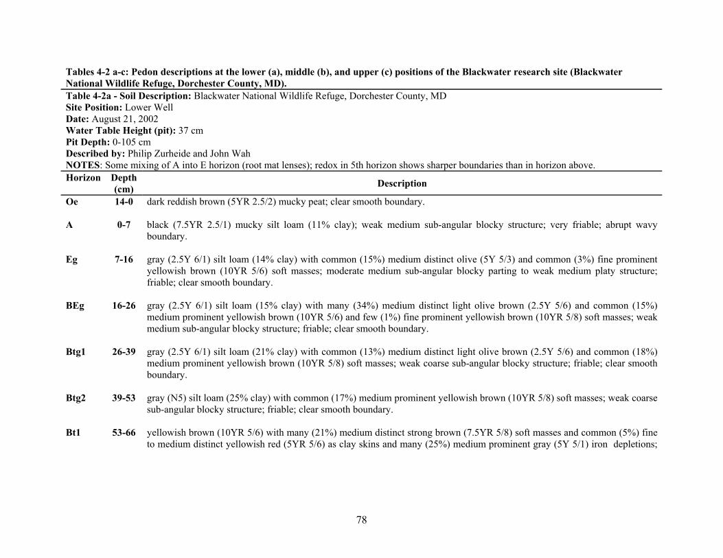
78
Tables 4-2 a-c: Pedon descriptions at the lower (a), middle (b), and upper (c) positions of the Blackwater research site (Blackwater National Wildlife Refuge, Dorchester County, MD). Table 4-2a - Soil Description: Blackwater National Wildlife Refuge, Dorchester County, MD Site Position: Lower Well Date: August 21, 2002 Water Table Height (pit): 37 cm Pit Depth: 0-105 cm Described by: Philip Zurheide and John Wah NOTES: Some mixing of A into E horizon (root mat lenses); redox in 5th horizon shows sharper boundaries than in horizon above. Horizon Depth
(cm) Description
Oe 14-0 dark reddish brown (5YR 2.5/2) mucky peat; clear smooth boundary. A 0-7 black (7.5YR 2.5/1) mucky silt loam (11% clay); weak medium sub-angular blocky structure; very friable; abrupt wavy
boundary. Eg 7-16 gray (2.5Y 6/1) silt loam (14% clay) with common (15%) medium distinct olive (5Y 5/3) and common (3%) fine prominent
yellowish brown (10YR 5/6) soft masses; moderate medium sub-angular blocky parting to weak medium platy structure; friable; clear smooth boundary.
BEg 16-26 gray (2.5Y 6/1) silt loam (15% clay) with many (34%) medium distinct light olive brown (2.5Y 5/6) and common (15%)
medium prominent yellowish brown (10YR 5/6) and few (1%) fine prominent yellowish brown (10YR 5/8) soft masses; weak medium sub-angular blocky structure; friable; clear smooth boundary.
Btg1 26-39 gray (2.5Y 6/1) silt loam (21% clay) with common (13%) medium distinct light olive brown (2.5Y 5/6) and common (18%)
medium prominent yellowish brown (10YR 5/8) soft masses; weak coarse sub-angular blocky structure; friable; clear smooth boundary.
Btg2 39-53 gray (N5) silt loam (25% clay) with common (17%) medium prominent yellowish brown (10YR 5/8) soft masses; weak coarse
sub-angular blocky structure; friable; clear smooth boundary. Bt1 53-66 yellowish brown (10YR 5/6) with many (21%) medium distinct strong brown (7.5YR 5/8) soft masses and common (5%) fine
to medium distinct yellowish red (5YR 5/6) as clay skins and many (25%) medium prominent gray (5Y 5/1) iron depletions;

79
weak coarse prismatic parting to moderate medium to thick platy structure; friable; clear smooth boundary. Bt2 66-77 olive (5Y 5/4) loam (26% clay) with common (13%) fine to medium prominent strong brown (7.5YR 5/8) soft masses with
common (7%) medium prominent and fine to medium distinct yellowish red (5YR 5/6) as clay skins and common (10%) medium faint olive gray (5Y 5/2) and common (15%) medium distinct gray (N5) iron depletions; weak coarse prismatic parting to moderate medium thick platy structure; friable (brittle); clear smooth boundary.
2BC 77-91 light olive brown (2.5Y 5/4) sandy loam (13% clay) with common 15%) medium to coarse prominent yellowish brown (10YR
5/8) and common (15%) fine to medium prominent strong brown (7.5YR 5/8) soft masses and common (18%) medium prominent grayish brown (2.5Y 5/2) iron depletions; weak to moderate thick platy and weak coarse prismatic structure; friable.
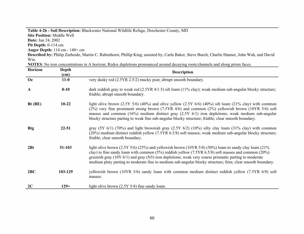
80
Table 4-2b - Soil Description: Blackwater National Wildlife Refuge, Dorchester County, MD Site Position: Middle Well Date: Jan 24, 2002 Pit Depth: 0-114 cm Auger Depth: 114 cm - 140+ cm Described by: Philip Zurheide, Martin C. Rabenhorst, Phillip King; assisted by, Carla Baker, Steve Burch, Charlie Hanner, John Wah, and David Win. NOTES: No iron concentrations in A horizon; Redox depletions pronounced around decaying roots/channels and along prism faces. Horizon Depth
(cm) Description
Oe 11-0 very dusky red (2.5YR 2.5/2) mucky peat; abrupt smooth boundary. A 0-10 dark reddish gray to weak red (2.5YR 4/1.5) silt loam (11% clay); weak medium sub-angular blocky structure;
friable; abrupt smooth boundary. Bt (BE) 10-22 light olive brown (2.5Y 5/6) (40%) and olive yellow (2.5Y 6/6) (40%) silt loam (21% clay) with common
(2%) very fine prominent strong brown (7.5YR 4/6) and common (2%) yellowish brown (10YR 5/6) soft masses and common (16%) medium distinct gray (2.5Y 6/1) iron depletions; weak medium sub-angular blocky structure parting to weak fine sub-angular blocky structure; friable; clear smooth boundary.
Btg 22-51 gray (5Y 6/1) (70%) and light brownish gray (2.5Y 6/2) (10%) silty clay loam (31% clay) with common
(20%) medium distinct reddish yellow (7.5YR 6.5/8) soft masses; weak medium sub-angular blocky structure; friable; clear smooth boundary.
2Bt 51-103 light olive brown (2.5Y 5/6) (25%) and yellowish brown (10YR 5/8) (50%) loam to sandy clay loam (21%
clay) to fine sandy loam with common (5%) reddish yellow (7.5YR 6.5/8) soft masses and common (20%) greenish gray (10Y 6/1) and gray (N5) iron depletions; weak very coarse prismatic parting to moderate medium platy parting to moderate fine to medium sub-angular blocky structure; firm; clear smooth boundary.
2BC 103-129 yellowish brown (10YR 5/6) sandy loam with common medium distinct reddish yellow (7.5YR 6/8) soft
masses. 2C 129+ light olive brown (2.5Y 5/4) fine sandy loam.

81

82
Table 4-2c - Soil Description: Blackwater National Wildlife Refuge, Dorchester County, MD Site Position: Upper Well Date: Jan 24, 2002 Pit Depth: 0-88 cm Auger Depth: 88 cm - 212 cm Described by: Philip Zurheide, Martin C. Rabenhorst, Phillip King; assisted by, Carla Baker, Steve Burch, Charlie Hanner, John Wah, and David Win. NOTES: Redox depletions pronounced around decaying roots/channels and along prism faces. Horizon Depth
(cm) Description
Oe 5-0 black (5YR 2.5/1) mucky peat; abrupt smooth boundary. A 0-10 very dark grayish brown to dark grayish brown (10YR 3.5/2) (97%) silt loam (9% clay) with common (3%) fine dark brown
(7.5YR 3/3) soft masses around roots; weak medium subangular blocky structure; friable; clear smooth boundary. EA 10-16 dark grayish brown to olive brown (2.5Y 4/2.7) (93%) silt loam (9% clay) with common (7%) fine dark brown (7.5YR 3/3)
soft masses; weak fine to medium subangular blocky structure; friable; abrupt smooth boundary. Bt1 16-33 light olive brown (2.5Y 5/4) (80%) silt loam (17.5% clay) with common (7%) strong brown (7.5YR 4/6) and common (3%)
dark brown (7.5YR 3/4) soft masses and common (5%) light olive brown (2.5Y 5/3.2) and common (5%) light brownish gray (2.5Y 6/2) iron depletions; weak medium subangular blocky structure; friable; clear to gradual smooth boundary.
Bt2 33-63 light olive brown (2.5Y 5/4) (65%) loam (23% clay) with common (10%) fine strong brown (7.5YR 4/6) soft masses and
common (10%) light olive brown (2.5Y 5/3) and common (15%) grayish brown (2.5Y 5/2) iron depletions; weak fine subangular blocky structure; friable; clear smooth boundary.
2BC1 63-83 yellowish brown (10YR 5/6) (65%) sandy loam (15% clay) with many (25%) medium faint dark yellowish brown (10YR 4/6)
soft masses and common (10%) grayish brown (2.5Y 5/2) iron depletions; weak medium platy parting to weak medium subangular blocky structure; friable; clear smooth boundary.
2BC2 83-173 Yellowish brown (10YR 5/6) loamy sand with strong brown (7.5YR 4/6) soft masses and light brownish gray (2.5Y 6/2) iron
depletions.

83
2BC3 173-207
yellowish brown (10YR 5/4) sandy loam with strong brown (7.5YR 4/6) soft masses and gray (2.5Y 6/1) iron depletions.

84
Tables 4-3 a-c: Pedon descriptions at the lower (a), middle (b), and upper (c) positions of the Isle of Wight research site (Isle of Wight Wildlife Management Area, Worcester County, MD). Table 4-3a - Soil Description: Isle of Wight Wildlife Management Area, Worcester County, MD Site Position: Lower Well Date: July 22, 2002 Pit Depth: 0-96+ cm Described by: Philip Zurheide, Martin C. Rabenhorst; Steve Burch, Karen Castenson, Cary Coppock, and Robert Vaughan Horizon Depth
(cm) Description
Oe 6-0 very dusky red (2.5YR 2.5/2) mucky peat; abrupt smooth boundary. A 0-9 very dark gray (2.5Y 3/1) (92%) sandy loam to loam (8% clay) with common (8%) distinct fine dark reddish brown (5YR
3/3) pore linings of iron; weak fine sub-angular blocky structure; friable; clear wavy boundary. B/A 9-27 light olive brown (2.5Y 5/4) (60%) and very dark grayish brown to dark grayish brown (2.5Y 3.5/2) (15%) sandy loam (14%
clay) with common (15%) medium distinct strong brown (7.5YR 4/6) soft masses and pore linings of iron and common (5%) fine prominent yellowish red (5YR 4/6) pore linings of iron and common (5%) medium to coarse faint very dark grayish brown to dark grayish brown (2.5Y 3.5/2) iron depletions; moderate medium sub-angular blocky structure; friable; clear smooth boundary.
Bt1 27-45 light olive brown (2.5Y 5/4) loam (18% clay) with many (25%) medium distinct strong brown (7.5YR 4/6) soft masses and
pore linings of iron and common (5%) fine prominent yellowish red (5YR 4/6) pore linings of iron and common (5%) medium to coarse faint grayish brown (2.5Y 5/2) iron depletions; moderate medium sub-angular blocky structure; friable; clear smooth boundary.
Bt2 45-60 dark yellowish brown (10YR 4/4) fine sandy loam (15% clay) with common (20%) medium to coarse faint strong brown
(7.5YR 5/6) soft masses of iron and common (5%) fine distinct strong brown (7.5YR 4/6) pore linings of iron and common (5%) moderate to coarse gray (2.5Y 5/1) iron depletions; weak moderate to coarse sub-angular blocky structure; friable; clear smooth boundary.
BC 60-
90+ light olive brown (2.5Y 5/4) loamy sand (6% clay) with common (20%) very coarse prominent yellowish brown (10YR 5/6) soft masses of iron and common (5%) medium to coarse prominent yellowish red (5YR 4/6) pore linings of iron and common (20%) very coarse faint dark grayish brown (2.5Y 5/2) iron depletions; structureless massive; very friable.

85
Table 4-3b - Soil Description: Isle of Wight Wildlife Management Area, Worcester County, MD Site Position: Middle Well Date: July 22, 2002 Pit Depth: 0-96+ cm Described by: Philip Zurheide, Martin C. Rabenhorst; Steve Burch, Karen Castenson, Cary Coppock, and Robert Vaughan Horizon Depth
(cm) Description
A 0-9 very dark brown (7.5YR 2.5/2) loam to sandy loam (10% clay) with few (1%) fine distinct dark reddish brown (5YR 5/4) pore linings of iron; moderate medium granular structure; very friable; clear smooth boundary.
AE 9-20 olive brown (2.5Y 4/4) loam to fine sandy loam (11% clay) with common (4%) fine to medium distinct yellowish red (5YR
4/6) pore linings of iron; weak fine sub-angular blocky parting to weak fine to medium granular structure; friable; clear smooth boundary.
EB 20-33 yellowish brown (10YR 5/6) sandy loam (9% clay) with common (6%) fine to medium distinct yellowish red (5YR 4/6) pore
linings of iron and common (5%) medium to coarse faint light olive brown (2.5Y 5/4) iron depletions; weak medium sub-angular blocky structure; friable; clear smooth boundary.
Bt1 33-49 dark yellowish brown (10YR 4/6) sandy loam (16% clay) with common (5%) fine distinct yellowish red (5YR 5/8) pore
linings of iron and common (15%) medium to coarse distinct light olive brown (2.5Y 5/3) iron depletions; moderate medium to coarse sub-angular blocky structure; friable; clear smooth boundary.
Bt2 49-70 dark yellowish brown (10YR 4/6) sandy loam (19% clay) with common (10%) coarse distinct strong brown (7.5YR 4/6) soft
masses of iron and common (2%) fine prominent yellowish red (5YR 5/8) pore linings of iron and light olive brown (2.5Y 5/3) iron depletions; moderate medium to coarse sub-angular blocky structure; friable; clear smooth boundary.
C1 70-89 yellowish brown (10YR 5/4) sandy loam to loamy sand (8% clay) with common (20%) coarse to very coarse faint yellowish
brown (10YR 5/6) soft masses of iron and common (3%) fine to medium prominent yellowish red (5YR 5/8) pore linings of iron and common (5%) medium to coarse faint light yellowish brown (2.5Y 6/4) iron depletions; very weak coarse sub-angular blocky structure; very friable; gradual smooth boundary.
C2 89-
125+ light olive brown (2.5Y 5/4) loamy sand to sand (4% clay) with common (5%) medium prominent yellowish red (5YR 5/8) pore linings of iron and many (25%) very coarse faint grayish brown (2.5Y 5/2) iron depletions; structureless single grain

86
lose; very friable.

87
Table 4-3c - Soil Description: Isle of Wight Wildlife Management Area, Worcester County, MD Site Position: Upper Well Date: July 22, 2002 Pit Depth: 0-96+ cm Auger Depth: 96-270+ cm Described by: Philip Zurheide, Martin C. Rabenhorst; Steve Burch, Karen Castenson, Cary Coppock, and Robert Vaughan Horizon Depth
(cm) Description
A 0-10 dark brown (7.5YR 3/2) loam to fine sandy loam (10% clay); moderate medium granular structure; friable; abrupt wavy boundary.
AB 10-18 brown (10YR 4/3) fine sandy loam (12% clay) with common (10%) medium distinct strong brown (7.5YR 4/6) and common
(5%) medium prominent dark reddish brown (5YR 3/4) soft masses of iron and common (3%) fine dark grayish brown (2.5Y 4/2) iron depletions; weak medium sub-angular blocky structure; friable; clear wavy boundary.
BA 18-31 light olive brown (2.5Y 5/4) fine sandy loam (13% clay) with many (35%) medium to coarse faint yellowish brown (10YR
5/6) soft masses of iron and common (3%) fine distinct strong brown (7.5YR 4/6) pore linings of iron; weak medium sub-angular blocky structure; friable; clear smooth boundary.
Bt1 31-55 yellowish brown (10YR 5/6) fine sandy loam (14% clay) with common (2%) fine prominent strong brown (7.5YR 5/8) pore
linings of iron and common (8%) coarse distinct light olive brown (2.5Y 5/3) iron depletions around roots and common (10%) medium to coarse faint light olive brown (2.5Y 5/4) iron depletions; weak coarse sub-angular blocky structure; friable; clear smooth boundary. yellowish brown (10YR 5/6) sandy loam (11% clay) with common (15%) medium distinct strong brown (7.5YR 4/6) soft masses and pore linings of iron and common (15%) medium to coarse distinct light yellowish brown (2.5Y 6/4) iron depletions; weak medium to coarse sub-angular blocky structure; friable; clear smooth boundary.
Bt2 55-77 yellowish brown (10YR 5/6) sandy loam (11% clay) with common (15%) medium distinct strong brown (7.5YR 4/6) soft
masses and pore linings of iron and common (15%) medium to coarse distinct light yellowish brown (2.5Y 6/4) iron depletions; weak medium to coarse sub-angular blocky structure; friable; clear smooth boundary.
BC 77-90 brownish yellow (10YR 6/6) loamy sand (6% clay) with common (20%) medium to coarse distinct strong brown (7.5YR 4/6)
soft masses of iron and common (3%) fine distinct strong brown (7.5YR 5/8) pore linings of iron and many (25%) coarse to very coarse distinct light yellowish brown (2.5Y 6/4) iron depletions; very weak medium to coarse sub-angular blocky
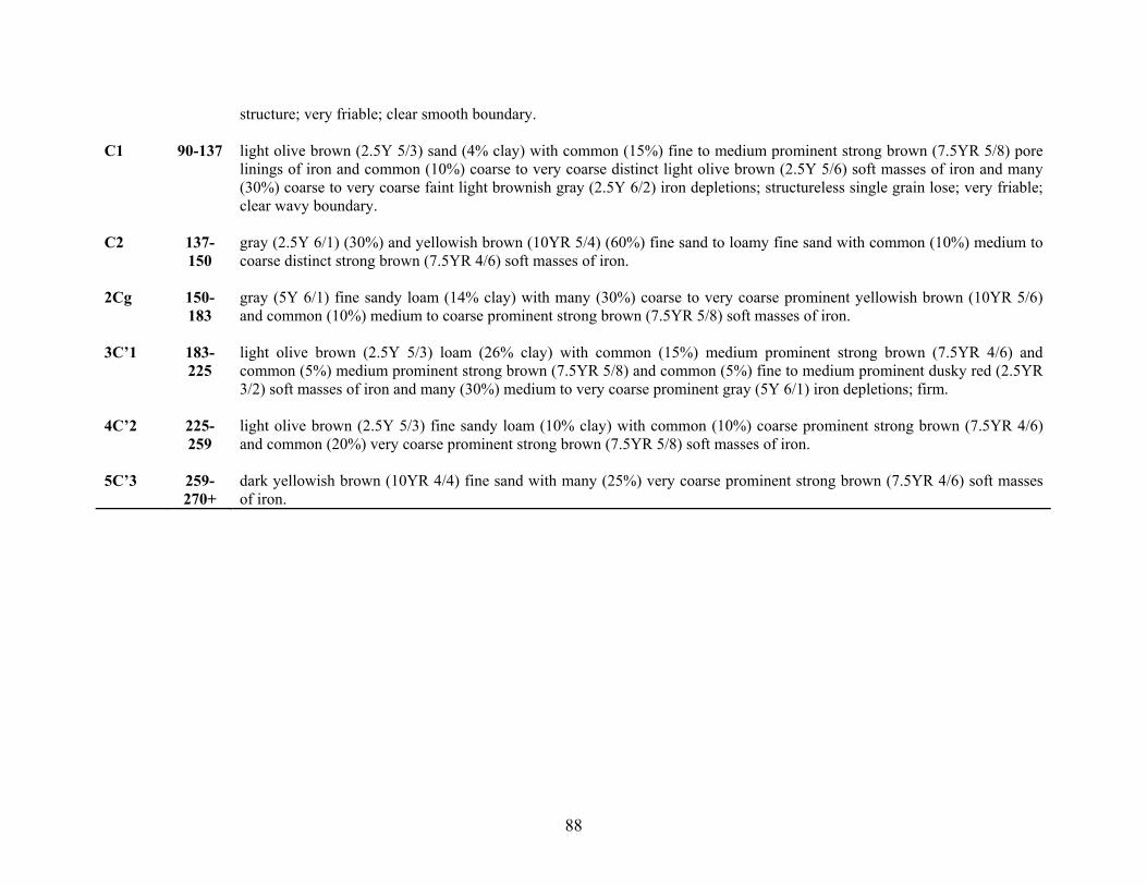
88
structure; very friable; clear smooth boundary. C1 90-137 light olive brown (2.5Y 5/3) sand (4% clay) with common (15%) fine to medium prominent strong brown (7.5YR 5/8) pore
linings of iron and common (10%) coarse to very coarse distinct light olive brown (2.5Y 5/6) soft masses of iron and many (30%) coarse to very coarse faint light brownish gray (2.5Y 6/2) iron depletions; structureless single grain lose; very friable; clear wavy boundary.
C2 137-
150 gray (2.5Y 6/1) (30%) and yellowish brown (10YR 5/4) (60%) fine sand to loamy fine sand with common (10%) medium to coarse distinct strong brown (7.5YR 4/6) soft masses of iron.
2Cg 150-
183 gray (5Y 6/1) fine sandy loam (14% clay) with many (30%) coarse to very coarse prominent yellowish brown (10YR 5/6) and common (10%) medium to coarse prominent strong brown (7.5YR 5/8) soft masses of iron.
3C’1 183-
225 light olive brown (2.5Y 5/3) loam (26% clay) with common (15%) medium prominent strong brown (7.5YR 4/6) and common (5%) medium prominent strong brown (7.5YR 5/8) and common (5%) fine to medium prominent dusky red (2.5YR 3/2) soft masses of iron and many (30%) medium to very coarse prominent gray (5Y 6/1) iron depletions; firm.
4C’2 225-
259 light olive brown (2.5Y 5/3) fine sandy loam (10% clay) with common (10%) coarse prominent strong brown (7.5YR 4/6) and common (20%) very coarse prominent strong brown (7.5YR 5/8) soft masses of iron.
5C’3 259-
270+ dark yellowish brown (10YR 4/4) fine sand with many (25%) very coarse prominent strong brown (7.5YR 4/6) soft masses of iron.

89
Tables 4-4 a-c: Pedon descriptions at the lower (a), middle (b), and upper (c) positions of the Eastern Neck Island research site (Eastern Neck Island National Wildlife Refuge, Kent County, MD). Table 4-4a - Soil Description: Eastern Neck Island National Wildlife Refuge, Kent County, MD Site Position: Lower Well Date: November 28, 2001 Pit Depth: 0-170 cm Auger Depth: 170 cm – 310 cm Described by: Philip Zurheide, Martin C. Rabenhorst, Phillip King; John Wah, Steve Burch, and Suzy Park. Horizon Depth
(cm) Description
Oe 3-2 dark brown (7.5YR 3/2) mucky peat; abrupt smooth boundary. A 0-6 very dark gray (10YR 3/1) silt loam (8% clay); moderate fine to medium granular structure; friable; common (10%) fine to
medium roots; abrupt smooth boundary. EA 6-15 brown (10YR 4/3) silt loam (10% clay) with few (1%) strong brown (7.5YR 4/6) soft masses; moderate very fine sub-angular
blocky structure; friable; common (10%) fine to medium roots; clear wavy boundary. BE 15-32 light yellowish brown (2.5Y 6/4) (40%) and (2.5Y 6/3) (25%) silt loam (13% clay) with common (5-10%) yellowish brown
(10YR 5/8) and common (10%) dark yellowish brown (10YR 4/6) soft masses and many (25%) light yellowish brown (2.5Y 6/3) iron depletions; weak course sub-angular blocky structure; friable to firm (brittle); common (5%) fine roots; clear smooth boundary.
Bt1 32-42 pale brown (10YR 6/3) silt loam (19% clay) with common (5%) dark reddish brown (5YR 3/4) soft masses and many (30%)
yellowish brown (10YR 5/6) iron depletions; weak course platy and moderate fine to medium sub-angular blocky structure; friable; common (5-10%) fine to medium roots; clear smooth boundary.
Bt2 42-62 yellowish brown (10YR 5/8) loam (22% clay) with many (25%) strong brown (7.5YR 5/6) and common (5%) dark reddish
brown (5YR 3/4) soft masses and many (30%) pale brown (10YR 6/3) iron depletions; weak course platy and moderate fine to medium sub-angular blocky structure; friable; common (6%) fine to medium roots; clear smooth boundary.
2Bt 62-77 yellowish brown (10YR 5/6) very fine sandy loam/loam (19% clay) with many (25%) strong brown (7.5YR 5/6) soft masses
and common (15%) light brownish gray (2.5Y 6/2) and many (25%) light yellowish brown (2.5Y 6/4) iron depletions; weak

90
very coarse prismatic and moderate medium to course platy and moderate fine to medium sub-angular blocky structure; friable to firm (slightly brittle); few fine to medium roots; clear smooth boundary.
2BC1 77-112 yellowish brown (10YR 5/4) fine sandy loam (19% clay) with many (25%) strong brown (7.5YR 4/6) soft masses and
common (10%) gray (2.5Y 6/1) iron depletions in areas of loamy fine sand and common (20%) light yellowish brown (2.5Y 6/4) mottles; weak to moderate very course prismatic and moderate to strong course platy structure; friable; very few fine roots; clear smooth boundary.
2BC2 112-
143 light olive brown (2.5Y 5/6) fine sandy loam (16% clay) with common (20%) yellowish brown (10YR 5/6) soft masses and common (20%) yellowish brown (2.5Y 6/4) and common (10%) gray (2.5Y 6/1) iron depletions; strong very course sub-angular blocky structure; friable; gradual smooth boundary.
2BC3 143-
167 yellowish brown (10YR 5/6) fine sandy loam (14% clay) with common (10%) strong brown (7.5YR 5/6) soft masses and many (25%) greenish gray (10Y 6/1) iron depletions; strong very course sub-angular blocky structure; friable; clear smooth boundary.
2BC4 167-
179 light gray (2.5Y 7/1) fine sandy loam (7% clay) with common (10%) light yellowish brown (2.5YR 6/3) and common (20%) reddish yellow (7.5YR 6/8) soft masses.
2C1 179-
199 light olive brown (2.5Y 5/3-4) fine sandy loam (12% clay) with common (20%) red (2.5YR 4/6) soft masses and common (5%) gray (2.5Y 6/1) iron depletions.
2C2 199-
215 light gray (2.5Y 7/1) fine sandy loam (9% clay) with common (5%) yellowish brown (10YR 5/6) soft masses and many (40%) light yellowish brown (2.5Y 6/3) iron depletions.
2C3 215-
257 light olive brown (2.5Y 5/3) very fine sandy loam (6% clay) with common (7%) strong brown (7.5YR 5/6) soft masses and common (5%) light gray (2.5Y 7/1) iron depletions.
2C4 257-307
light olive brown (2.5Y 5/4) very fine sandy loam (9% clay) with common (10%) strong brown (7.5 YR 5/6) soft masses.

91
Table 4-4b - Soil Description: Eastern Neck Island National Wildlife Refuge, Kent County, MD Site Position: Middle Well Date: November 28, 2001 Pit Depth: 0-150 cm Auger Depth: 150 cm – 240 cm Described by: Philip Zurheide, Martin C. Rabenhorst, Phillip King; John Wah, Steve Burch, and Suzy Park. Horizon Depth
(cm) Description
Oe 3-0 mucky peat; abrupt smooth boundary. A 0-9 very dark gray (10YR 3/1) silt loam (8% clay); moderate fine to medium granular structure; very friable; clear wavy
boundary; common fine to medium roots. AE 9-15 brown (10YR 4/3) silt loam (10% clay); moderate fine to medium sub-angular blocky structure; very friable; clear wavy
boundary; common fine to medium roots. BE 15-28 light yellowish brown (2.5Y 6/4) silt loam (14% clay) with many (30%) yellowish brown (10YR 5/6) soft masses of iron;
weak medium to coarse sub-angular blocky structure; friable; clear smooth boundary; common fine to medium roots. Bt1 28-45 strong brown (7.5YR 5/6) silt loam (21% clay) with many (30%) yellowish brown (10YR 5/8) soft masses of iron and
common (20%) light yellowish brown (2.5Y 6/4) and common (10%) light yellowish brown (2.5Y 6/3) iron depletions; moderate fine to medium sub-angular blocky structure; friable; clear smooth boundary; common fine to medium roots.
Bt2 45-69 light brown (7.5YR 6/4) (30%) and yellowish brown (10YR 5/6) (30%) loam (18% clay) with many (25%) strong brown
(7.5YR 5/8) soft masses of iron and common (5%) brown (10YR 5/3) and common (10%) light gray (2.5Y 7/2) iron depletions; moderate medium to coarse sub-angular blocky structure; friable gradual smooth boundary; common medium roots.
2Bt3 69-92 yellowish brown (10YR 5/6) fine sandy loam (15% clay) with common (5%) yellowish red (5YR 4/6) and many (25%) strong
brown (7.5YR 5/8) and many (30%) light yellowish brown (2.5Y 6/4) soft masses of iron and light brownish gray (2.5Y 6/2) and light brownish gray (10YR 6/2) iron depletions; moderate coarse sub-angular blocky with some weak medium to coarse prismatic structure; friable to firm; slightly brittle; clear smooth boundary; common fine to medium roots.

92
2BC1 92-137 gray (10YR 5/1) fine sandy loam (13% clay) with common (15%) yellowish brown (10YR 5/8) soft masses of iron and common (15%) light yellowish brown (2.5Y 6/3) occurring in loamy sand textures and common (20%) light gray (2.5Y 7/2) and common (5%) greenish gray (5GY 6/1) occurring in heavy sandy loam textures as iron depletions; weak medium to very coarse prismatic parting to moderate medium to coarse platy structure; friable; clear smoother boundary.
2BC2 137-
157 light yellowish brown (2.5Y 6/4) sandy clay loam (23% clay) with common (10%) yellowish brown (10YR 5/8) soft masses of iron and many (30%) gray (10YR 6/1) iron depletions.
2C1 157-
192 light yellowish brown (2.5Y 6/4) very fine sandy loam (14% clay) with many (40%) yellowish (10YR 5/6) soft masses of iron and common (10%) light gray (2.5Y 7/1) iron depletions.
2C2 192-
237 light yellowish brown (2.5Y 6/3) very fine sandy loam with common (5%) strong brown (7.5YR 5/8) soft masses of iron.

93
Table 4-4c - Soil Description: Eastern Neck Island National Wildlife Refuge, Kent County, MD Site Position: Upper Well Date: August 22, 2002 Pit Depth: 0-155 cm Described by: Philip Zurheide, John Wah, and Robert Vaughan. Horizon Depth
(cm) Description
A 0-6 dark brown (10YR 3/3) loam/silt loam (9% clay); weak fine granular structure; very friable; clear smooth boundary. AE 6-14 dark yellowish brown (10YR 4/4) silt loam/loam (11% clay); weak fine sub-angular blocky structure; very friable; clear wavy
boundary. EB 14-38 light yellowish brown (2.5Y 6/4) silt loam (12% clay) with few (1%) fine faint strong brown (7.5 YR 5/6) pore linings of iron
and common (5%) medium distinct yellowish brown (10YR 5/6) soft masses; moderate medium sub-angular blocky structure; friable; clear smooth boundary.
Bt1 38-56 olive yellow (2.5Y 6/6) loam-silt loam (14% clay) with common (8%) medium distinct yellowish brown (10YR 5/8) soft
masses and many (25%) medium to coarse faint light yellowish brown (2.5Y 6/4) iron depletions; moderate medium sub-angular blocky structure; friable; clear smooth boundary.
Bt2 56-69 yellowish brown (10YR 5/8) loam-fine sandy loam (12% clay) with many (25%) medium distinct strong brown (7.5YR 5/6)
soft masses and many (25%) medium prominent light brownish gray (2.5Y 6/2) iron depletions; weak coarse prismatic parting to moderate medium sub-angular blocky structure; friable; clear smooth boundary.
BCt 69-90 yellowish brown (10YR 5/6) fine sandy loam (8% clay) with common (10%) medium faint yellowish brown (10YR 5/8) soft
masses and light yellowish brown (2.5Y 6/4) and light yellowish gray (2.5Y 6/2) iron depletion as 1-inch diameter root channel through horizon; weak coarse prismatic parting to moderate medium platy structure; friable; abrupt smooth boundary.
2Bt 90-104 light yellowish brown (2.5Y 6/4) clay loam (33% clay) with many (25%) medium prominent strong brown (7.5YR 5/8) soft
masses and common (19%) medium prominent gray (2.5Y 6/1) iron depletions; weak coarse prismatic parting to weak to moderate medium sub-angular blocky structure; friable; clear smooth boundary.
2BC1 104- olive yellow (2.5Y 6/6) fine sandy loam (8% clay) with common (8%) medium distinct yellowish brown (10YR 5/8) and few

94
121 (1%) fine prominent strong brown (7.5YR 4/6) pore linings of iron and common (8%) coarse prominent light olive gray (5Y 6/2) iron depletions; weak coarse prismatic parting to moderate medium sub-angular blocky structure; friable clear smooth boundary.
2BC2 121-
155 light olive brown (2.5Y 5/4) sandy loam (8% clay) with many (40%) coarse to very coarse gray (5Y 6/1) iron depletions as discontinuous lenses to 3 inches thick and common (10%) medium distinct yellowish brown (10YR 5/6) soft masses around depleted lenses as noted above; weak medium sub-angular blocky and weak medium platy structure; friable.
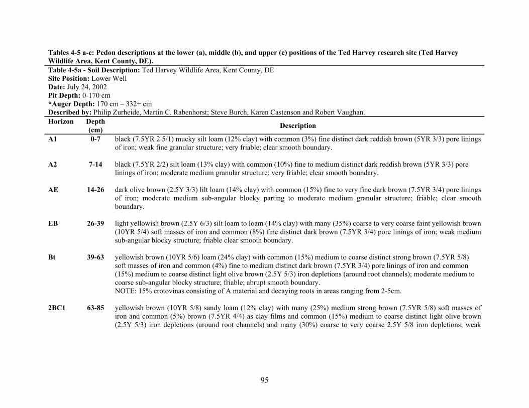
95
Tables 4-5 a-c: Pedon descriptions at the lower (a), middle (b), and upper (c) positions of the Ted Harvey research site (Ted Harvey Wildlife Area, Kent County, DE). Table 4-5a - Soil Description: Ted Harvey Wildlife Area, Kent County, DE Site Position: Lower Well Date: July 24, 2002 Pit Depth: 0-170 cm *Auger Depth: 170 cm – 332+ cm Described by: Philip Zurheide, Martin C. Rabenhorst; Steve Burch, Karen Castenson and Robert Vaughan. Horizon Depth
(cm) Description
A1 0-7 black (7.5YR 2.5/1) mucky silt loam (12% clay) with common (3%) fine distinct dark reddish brown (5YR 3/3) pore linings of iron; weak fine granular structure; very friable; clear smooth boundary.
A2 7-14 black (7.5YR 2/2) silt loam (13% clay) with common (10%) fine to medium distinct dark reddish brown (5YR 3/3) pore
linings of iron; moderate medium granular structure; very friable; clear smooth boundary. AE 14-26 dark olive brown (2.5Y 3/3) lilt loam (14% clay) with common (15%) fine to very fine dark brown (7.5YR 3/4) pore linings
of iron; moderate medium sub-angular blocky parting to moderate medium granular structure; friable; clear smooth boundary.
EB 26-39 light yellowish brown (2.5Y 6/3) silt loam to loam (14% clay) with many (35%) coarse to very coarse faint yellowish brown
(10YR 5/4) soft masses of iron and common (8%) fine distinct dark brown (7.5YR 3/4) pore linings of iron; weak medium sub-angular blocky structure; friable clear smooth boundary.
Bt 39-63 yellowish brown (10YR 5/6) loam (24% clay) with common (15%) medium to coarse distinct strong brown (7.5YR 5/8)
soft masses of iron and common (4%) fine to medium distinct dark brown (7.5YR 3/4) pore linings of iron and common (15%) medium to coarse distinct light olive brown (2.5Y 5/3) iron depletions (around root channels); moderate medium to coarse sub-angular blocky structure; friable; abrupt smooth boundary. NOTE: 15% crotovinas consisting of A material and decaying roots in areas ranging from 2-5cm.
2BC1 63-85 yellowish brown (10YR 5/8) sandy loam (12% clay) with many (25%) medium strong brown (7.5YR 5/8) soft masses of
iron and common (5%) brown (7.5YR 4/4) as clay films and common (15%) medium to coarse distinct light olive brown (2.5Y 5/3) iron depletions (around root channels) and many (30%) coarse to very coarse 2.5Y 5/8 iron depletions; weak
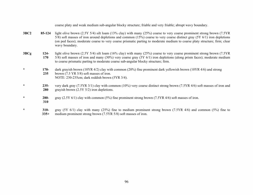
96
coarse platy and weak medium sub-angular blocky structure; friable and very friable; abrupt wavy boundary. 3BC2 85-124 light olive brown (2.5Y 5/4) silt loam (13% clay) with many (25%) coarse to very coarse prominent strong brown (7.5YR
5/8) soft masses of iron around depletions and common (15%) coarse to very coarse distinct gray (5Y 6/1) iron depletions (on ped faces); moderate coarse to very coarse prismatic parting to moderate medium to coarse platy structure; firm; clear wavy boundary.
3BCg 124-
170 light olive brown (2.5Y 5/4) silt loam (16% clay) with many (25%) coarse to very coarse prominent strong brown (7.5YR 5/8) soft masses of iron and many (30%) very coarse gray (5Y 6/1) iron depletions (along prism faces); moderate medium to coarse prismatic parting to moderate coarse sub-angular blocky structure; firm.
* 170-
235 dark grayish brown (10YR 4/2) clay with common (20%) fine prominent dark yellowish brown (10YR 4/6) and strong brown (7.5 YR 5/8) soft masses of iron. NOTE: 230-235cm; dark reddish brown (5YR 3/4).
* 235-
280 very dark gray (7.5YR 3/1) clay with common (10%) very coarse distinct strong brown (7.5YR 4/6) soft masses of iron and grayish brown (2.5Y 5/2) iron depletions.
* 280-
310 gray (2.5Y 6/1) clay with common (5%) fine prominent strong brown (7.5YR 4/6) soft masses of iron.
* 310-
335+ gray (5Y 6/1) clay with many (25%) fine to medium prominent strong brown (7.5YR 4/6) and common (5%) fine to medium prominent strong brown (7.5YR 5/8) soft masses of iron.

97
Table 4-5b - Soil Description: Ted Harvey Wildlife Area, Kent County, DE Site Position: Middle Well Date: July 24, 2002 Pit Depth: 0-148 cm Described by: Philip Zurheide, Martin C. Rabenhorst; Steve Burch, Karen Castenson and Robert Vaughan. Horizon Depth
(cm) Description
A 0-14 very dark brown (10YR 2/2) silt loam to loam (14% clay); moderate medium granular structure; very friable; clear smooth boundary.
AE 14-26 brown (10YR 4/3) loam to silt loam (14% clay) with common (3%) fine distinct strong brown (7.5YR 4/6) pore linings of
iron; weak medium sub-angular blocky structure; very friable; clear wavy boundary. NOTE: 15% crotovinas consisting of A material throughout.
BE 26-40 light olive brown (2.5Y 5/4) loam (16% clay) with common fine distinct strong brown (7.5YR 4/6) pore linings of iron and
common (5%) medium to coarse faint light olive brown (2.5Y 5/3) iron depletions; weak coarse sub-angular blocky structure; friable; clear smooth boundary. NOTE: 8% crotovinas consisting of A material throughout
Bt1 40-68 yellowish brown (10YR 5/6) loam (21% clay) with common (10%) medium to coarse distinct strong brown (7.5YR 5/8) soft
masses of iron and common (3%) fine to medium distinct yellowish red (5YR 4/6) pore linings of iron and common (15%) medium to coarse distinct light olive brown (2.5Y 5/3) iron depletions (on ped faces); moderate medium to coarse sub-angular blocky structure; friable; gradual wavy boundary.
Bt2 68-94 yellowish brown (10YR 5/6) (25%) and (10YR 5/8) (25%) loam (19% clay) with common (5%) medium to very coarse
distinct yellowish red (5YR 4/6) and common (15%) medium to very coarse distinct strong brown (7.5YR 4/6) soft masses of iron and many (30%) coarse to very coarse prominent light brownish gray (2.5Y 6/2) iron depletions; moderate medium to coarse sub-angular blocky structure; friable; abrupt smooth boundary.
2BC1 94-118 yellowish brown (10YR 4/5) sandy loam (11% clay) with common (5%) medium to coarse distinct strong brown (7.5YR 4/6)
and common (5%) medium to coarse distinct strong brown (7.5YR 5/6) soft masses of iron and many (25%) coarse to very coarse prominent gray (2.5Y 6/1) iron depletions; weak coarse sub-angular blocky structure; friable; abrupt wavy boundary.

98
3BC2 118-130
light olive brown (2.5Y 5/4) silt loam (23% clay) with many (25%) medium to coarse distinct strong brown (7.5YR 4/6) soft masses and pore linings of iron and many (35%) coarse to very coarse prominent gray (5Y 6/1) iron depletions; moderate medium sub-angular blocky structure; firm; abrupt wavy boundary.
4BC3 130-
148+ dark yellowish brown (10YR 4/6) loamy sand (5% clay) with common (5%) medium to coarse distinct strong brown (7.5YR 4/6) soft masses of iron and common (15%) coarse to very coarse prominent light brownish gray (2.5Y 6/2) iron depletions; weak coarse sub-angular blocky structure; friable to very friable.

99
Table 4-5c - Soil Description: Ted Harvey Wildlife Area, Kent County, DE Site Position: Upper Well Date: July 24, 2002 Coordinates: N 39° 05’ 16.13” W 75° 24’ 23.13” Pit Depth: 0-142 cm Described by: Philip Zurheide, Martin C. Rabenhorst; Steve Burch, Karen Castenson and Robert Vaughan. Horizon Depth
(cm) Description
A 0-9 very dark grayish brown (10YR 3/2) silt loam (11% clay); moderate medium granular structure; friable; clear smooth boundary.
AE 9-20 brown (10YR 4/3) silt loam (13% clay) with common (10%) fine to medium faint dark brown (7.5YR 3/4) soft masses of
iron; weak medium sub-angular blocky structure; friable; clear wavy boundary. EB 20-33 light olive brown (2.5Y 5/4) silt loam (16% clay) with few (1%) medium faint dark yellowish brown (10YR 4/4) pore linings
of iron and common (5%) medium faint light olive brown (2.5Y 5/3) iron depletions; weak medium to coarse platy parting to weak medium to coarse sub-angular blocky structure; friable; clear smooth boundary. NOTE: 5% inclusions of A-material as crotovinas.
Bt1 33-53 yellowish brown (10YR 5/6) silt loam (22% clay) with common (3%) fine distinct strong brown (7.5YR 4/6) soft masses of
iron and common (15%) medium to very coarse prominent dark yellowish brown (10YR 3/4) pore linings of iron and common (8%) medium prominent light brownish gray (2.5Y 6/2) iron depletions along root channels; moderate medium to coarse prismatic parting to moderate medium to coarse sub-angular blocky structure; friable; clear smooth boundary.
Bt2 52-68 yellowish brown (10YR 5/6) silt loam (21% clay) with common (10%) medium to coarse prominent dark yellowish brown
(10YR 3/4) pore linings of iron and common (10%) medium to coarse distinct strong brown (7.5YR 5/6) soft masses of iron and many (25%) medium prominent light brownish gray (2.5Y 6/2) iron depletions along root channels and ped faces; moderate medium to coarse sub-angular blocky structure; friable; clear wavy boundary.
2Bt3 68-83 yellowish brown (10YR 5/6) fine sandy loam (14% clay) with common (20%) medium to coarse distinct strong brown
(7.5YR 5/6) and common (20%) medium to coarse distinct yellowish brown (10YR 5/4) soft masses of iron and common (15%) medium to very coarse distinct light yellowish brown (2.5Y 6/3) and common (5%) medium to very coarse prominent light yellowish gray (2.5Y 6/2) iron depletions; moderate medium sub-angular blocky structure; friable; abrupt smooth

100
boundary. 2BC1 83-105 strong brown (7.5YR 5/6) (20%) and yellowish brown (10YR 5/6) (40%) sandy loam to loamy sand (8% clay) with faint
medium to coarse strong brown (7.5YR 4/6) soft masses of iron and common (5%) distinct pale brown (10YR 6/3) and common (5%) distinct light olive brown (2.5Y 5/3) iron depletions; weak very coarse platy parting to weak coarse sub-angular blocky structure; friable; clear wavy boundary.
2BC2 105-
125 light olive brown (2.5Y 5/6) sandy loam (15% clay) with common (10%) medium to coarse strong brown (7.5YR 4/6) soft masses of iron and common (5%) coarse to very coarse prominent gray (2.5Y 6/1) and common (10%) coarse to very coarse faint light olive brown (2.5Y 5/4) iron depletions; weak medium to coarse sub-angular blocky structure; friable; abrupt wavy boundary. NOTE: horizon extends down on right side.
3BC3 125-
142 light olive brown (2.5Y 5/4) silty clay loam (28% clay) with common (15%) medium to coarse distinct yellowish brown (10YR 5/6) iron concentrations and many (25%) coarse to very coarse distinct gray (2.5Y 5/1) iron depletions; moderate medium sub-angular blocky structure; firm. NOTE: representative material more on left side of pit.

101
Surface Horizons
The degree of development of organic surface horizons (O-horizons) was
influenced by how long the soil experienced saturation. The Blackwater site was the
wettest of all sites and had highly developed organic horizons at all three site positions.
Organic horizon thickness increased from 5 cm (upper position) to 14 cm (lower
position).
The Ted Harvey site was considered the driest of all four sites where water tables
remained below the soil surface for nearly the entire year. Here, no organic horizons
were described. Organic matter accumulation in soil surface horizons as O-horizons, was
directly related to the degree that these soils experienced water tables to the surface; as
the frequency and duration of saturation events increased, so did the amount of organic
matter in these horizons. Figure 4-4 illustrates this relationship between the thickness of
O-horizons in ABLS soils and their cumulative length of saturation at the mineral soil
surface.
Saturation to the Mineral Surface of ABLS-soils
R2 = 0.99
0
2
4
6
8
10
12
14
16
0 10 20 30 40 50 60 70 80 90 100
Percent Cumulative Saturation
O-H
oriz
on T
hick
ness
(cm
)
Figure 4-4: O-horizon thickness of twelve ABLS pedons as a function of the length of time the soil experienced saturation to the mineral surface.

102
Iron Concentrations
No distinct or prominent redoximorphic features were described in horizons that
were saturated for less than 22% of the year. Distinct and prominent redoximorphic iron
concentrations were observed in ABLS-soils (excluding horizons that had redox
depletions of chroma ≤ 2) when the duration of saturation ranged between 22-82%, with
an average of 54%. The abundance of these features was positively related to the length
of time the soil was saturated (Fig. 4-5) and increased to an average maximum of
approximately 17% when the soils were saturated for approximately 64% of the time.
These data were compared with data from several other studies that also related
the duration of saturation to the development of distinct and prominent Fe-concentrations
without depletions of chroma ≤ 2 (Fig. 4-6). In these other studies, soils containing
horizons with distinct and prominent concentrations (without 2-chroma depletions), the
average time that these horizons were saturated ranged between 2% and 44%. In
contrast, in ABLS-soils, the average length of saturation for horizons with concentrations
(without low-chroma depletions) was 56%.
An Analysis of Variance (ANOVA) was run on these data to determine whether
or not the differences observed between ABLS-soils and other studies were significant;
these results are shown in figure 4-7. Results tended to segregate into two groups; the
studies by Jacobs et al. (2002), Morgan and Stolt (2006), Galusky (1997), and West et al.
(1998) generally reported results rather similar to one another. The second group
included the results of the Castenson (2004) study and the ABLS-soils study, which were
not significantly different from one another, but were significantly different from the

103
results of the other studies in that they required significantly longer saturation periods to
exhibit redox concentrations.
Occurrence of Fe-Concentrations in ABLS(in soil horizons without <= 2 Chroma colors)
R2 = 0.6736
05
101520253035404550
0 10 20 30 40 50 60 70 80 90 100
Cumulative Saturation (%)
Abu
ndan
ce o
f Fea
ture
(%)
Data means of data Linear (means of data)
Figure 4-5: Abundance of iron concentrations in ABLS-soils (without depletions ≤ 2 chroma) increases with increasing saturation. Solid dots show means of 10% cumulative saturation increments and bars show SE of the means.
0 10 20 30 40 50 60 70 80 90 100Cumulative Saturation (%)
ABLS C W G M J Figure 4-6: Means (center points) and ranges (end points) of cumulative saturation data of soil horizons with iron concentrations, but without chroma ≤ 2 depletions, for the ABLS-soils and for soils reported in other studies. ABLS=this study, C=Castenson, 2004 (PFP-study); G=Galusky, 1997; J=Jacobs et al., 2002; M=Morgan and Stolt, 2006; W=West et al., 1998.
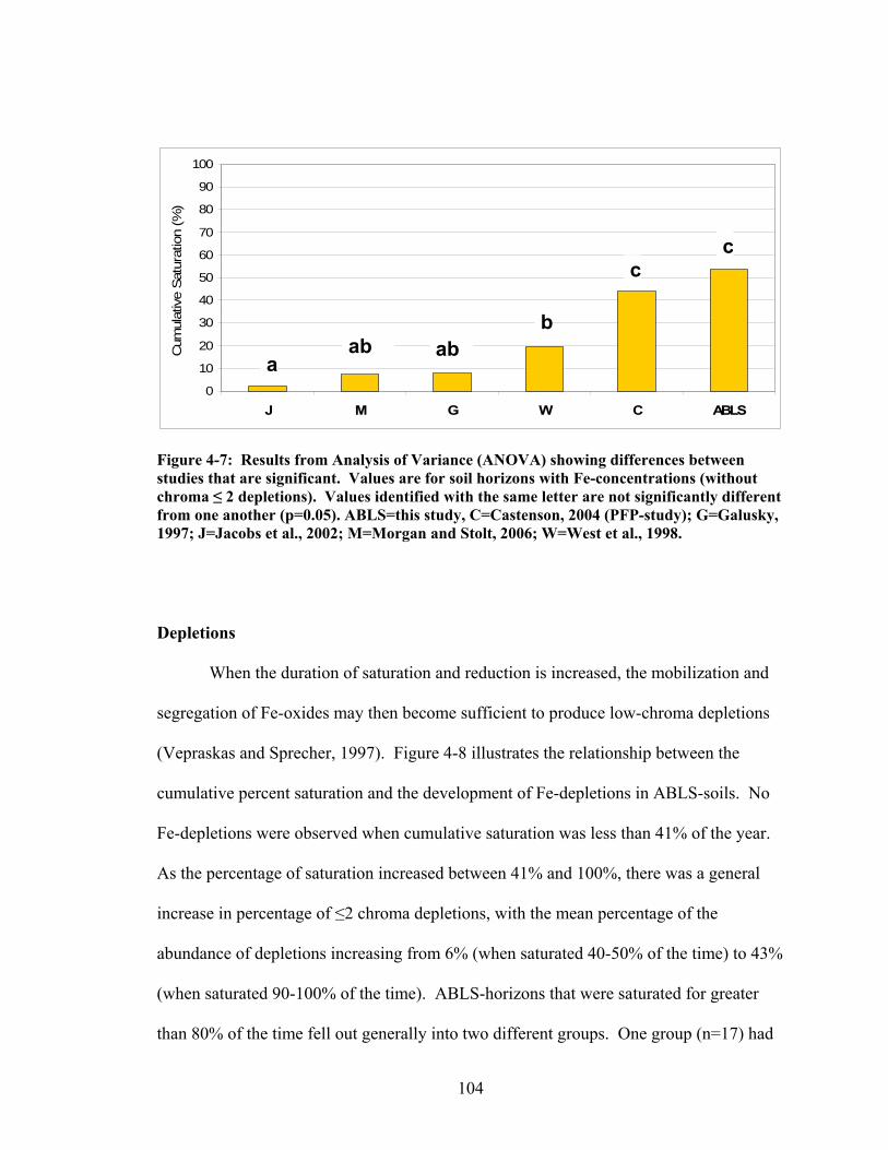
104
Figure 4-7: Results from Analysis of Variance (ANOVA) showing differences between studies that are significant. Values are for soil horizons with Fe-concentrations (without chroma ≤ 2 depletions). Values identified with the same letter are not significantly different from one another (p=0.05). ABLS=this study, C=Castenson, 2004 (PFP-study); G=Galusky, 1997; J=Jacobs et al., 2002; M=Morgan and Stolt, 2006; W=West et al., 1998.
Depletions
When the duration of saturation and reduction is increased, the mobilization and
segregation of Fe-oxides may then become sufficient to produce low-chroma depletions
(Vepraskas and Sprecher, 1997). Figure 4-8 illustrates the relationship between the
cumulative percent saturation and the development of Fe-depletions in ABLS-soils. No
Fe-depletions were observed when cumulative saturation was less than 41% of the year.
As the percentage of saturation increased between 41% and 100%, there was a general
increase in percentage of ≤2 chroma depletions, with the mean percentage of the
abundance of depletions increasing from 6% (when saturated 40-50% of the time) to 43%
(when saturated 90-100% of the time). ABLS-horizons that were saturated for greater
than 80% of the time fell out generally into two different groups. One group (n=17) had
0
10
20
30
40
50
60
70
80
90
100
J M G W C ABLS
Cum
ulat
ive
Satu
ratio
n (%
)
aab ab
b
cc

105
brown matrix colors with common to many depletions of ≤ 2 chroma. A smaller group
(n=8) had depleted matrices with 50% to 80% chroma ≤ 2. Figure 4-9 shows the means
and ranges of cumulative percentage of saturation in soil horizons showing depletions
with chroma ≤ 2 for similar projects in other pedological settings. In three out of four of
the projects (Galusky et al., 1998; Jacobs et al., 2002; Morgan and Stolt, 2006), Fe-
depletions were present when the mean cumulative percentage of saturation was
approximately 20%. The study by West et al. (1998) showed Fe-depletions in horizons
that were saturated between 10% and 62% of the time (mean saturation of 42%). Work
by Castenson (2004), focusing on problematic soils of the Mid-Atlantic Piedmont
floodplains, showed that these soils required a greater length of saturation to develop
depletions of chroma ≤ 2. The average percentage of saturation for PFP-soils showing
common Fe-depletions was 71% (range 26-95%). An analysis of variance (ANOVA)
was run on these data to determine whether or not differences between ABLS-soils and
other soils were significant. Figure 4-10 shows that the studies by Jacobs (2002), Morgan
and Stolt (2006), and Galusky (1997), and West (1998) were all relatively similar to one
another. The results of the problematic PFP-soils (Castenson, 2004) and the ABLS-soils
were similar to one another but different from the other studies requiring significantly
longer saturation to show comparable expression of redox depletions.
For the ABLS-soils, the mean percent saturation for horizons with a depleted
matrix was 96% with a range of 82-100%. Most of the studies indicate soils showing a
depleted matrix have a mean cumulative saturation percentage that ranged from 40% to
60% (Fig. 4-11). Only the study by Castenson, which focused on problematic soils of

106
Piedmont floodplains, showed significantly higher cumulative saturation percentages for
horizons with depleted matrices, with a means of 93% saturation (range of 40-100%).
An Analysis of Variance (ANOVA) was run on these data to determine whether
or not the differences observed between ABLS-soils and other studies were significant.
Figures 4-12 shows how results tended to segregate into two groups. The first group
(Jacobs, 2002, Morgan and Stolt, 2006, Galusky, 1997, West, 1998) had results that were
generally similar to one another. The second group included the PFP-study (Castenson,
2004) and the ABLS-study, which were similar to one another but statistically different
from the other studies, requiring significantly longer saturation to show a depleted matrix.
Abundance of Chroma Colors ≤ 2 in ABLS Soil Horizons
R2 = 0.8506
0
10
20
30
40
50
60
70
80
90
100
0 10 20 30 40 50 60 70 80 90 100
Cumulative Saturation (%)
Abu
ndan
ce o
f Fea
ture
(%)
data means of data Linear (means of data)
Figure 4-8: Data showing abundance of depletions (≤ 2 chroma) in ABLS-soils as a function of percentage of time the horizon was saturated. Open circles represent data from individual soil horizons, while solid circles represent means for horizons falling within a ten percentage point range for cumulative saturation ranges (40-50, 50-60, 60-70, 70-80, 80-90, and 90-100). When cumulative saturation was > 80%, soil horizons fell out into two groups;
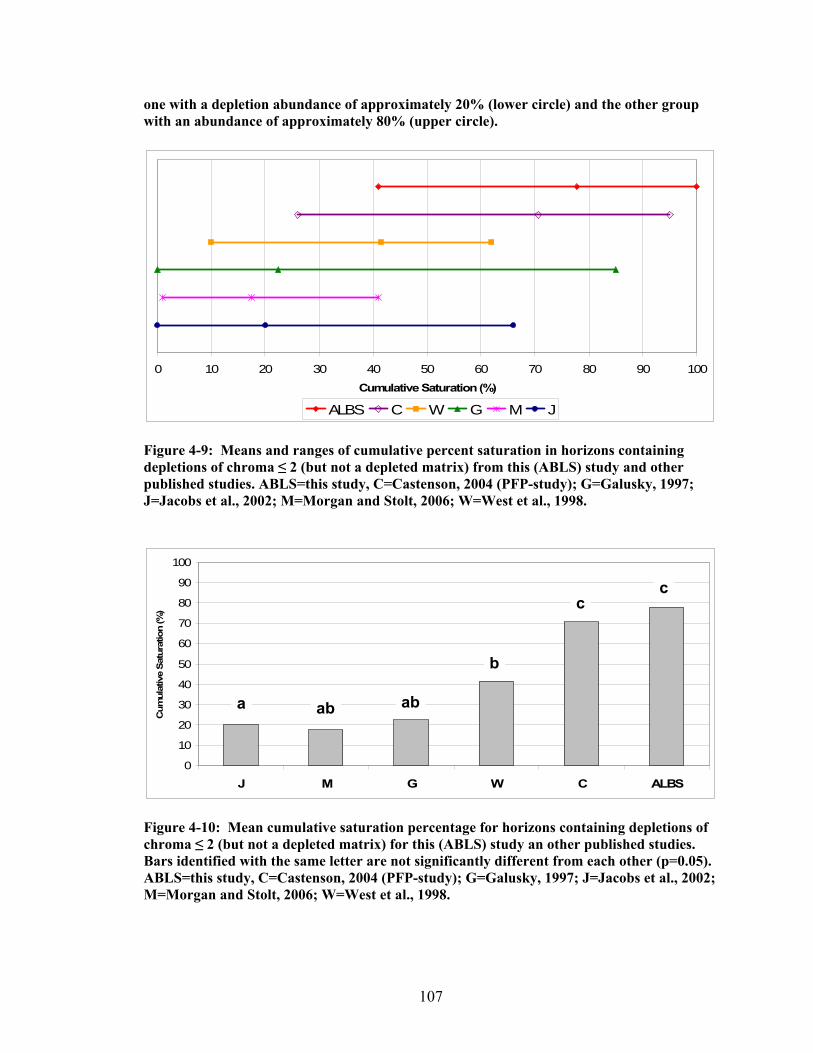
107
one with a depletion abundance of approximately 20% (lower circle) and the other group with an abundance of approximately 80% (upper circle).
0 10 20 30 40 50 60 70 80 90 100Cumulative Saturation (%)
ALBS C W G M J
Figure 4-9: Means and ranges of cumulative percent saturation in horizons containing depletions of chroma ≤ 2 (but not a depleted matrix) from this (ABLS) study and other published studies. ABLS=this study, C=Castenson, 2004 (PFP-study); G=Galusky, 1997; J=Jacobs et al., 2002; M=Morgan and Stolt, 2006; W=West et al., 1998.
0
10
20
30
40
50
60
70
80
90
100
J M G W C ALBS
Cum
ulat
ive
Satu
ratio
n (%
)
Figure 4-10: Mean cumulative saturation percentage for horizons containing depletions of chroma ≤ 2 (but not a depleted matrix) for this (ABLS) study an other published studies. Bars identified with the same letter are not significantly different from each other (p=0.05). ABLS=this study, C=Castenson, 2004 (PFP-study); G=Galusky, 1997; J=Jacobs et al., 2002; M=Morgan and Stolt, 2006; W=West et al., 1998.
a ab ab
b
c c

108
0 10 20 30 40 50 60 70 80 90 100Cumulative Saturation (%)
ABLS C W G M J
Figure 4-11: Means (center points) and ranges (end points) of cumulative saturation percentages for soil horizons in this (ABLS) study and in other similar studies that have a depleted matrix. ABLS=this study, C=Castenson, 2004 (PFP-study); G=Galusky, 1997; J=Jacobs et al., 2002; M=Morgan and Stolt, 2006; W=West et al., 1998.
0
10
20
30
40
50
60
70
80
90
100
M G W J C ABLS
Cum
ulat
ive
Satu
ratio
n (%
)
Figure 4-12: Mean cumulative saturation of horizons with a depleted matrix in this (ABLS) study and in other published studies. Bars identified with the same letter are not significantly different from each other (p=0.05). ABLS=this study, C=Castenson, 2004 (PFP-study); G=Galusky, 1997; J=Jacobs et al., 2002; M=Morgan and Stolt, 2006; W=West et al., 1998.
a
ab b b
c c

109
0
10
20
30
40
50
60
70
80
90
100
0 10 20 30 40 50 60 70 80 90 100
Cumulative Saturation (%)
Abu
ndan
ce o
f Fea
ture
(%)
Concentrations (w/o depletions) Depletions Depleted Matrix
Figure 4-13: Cumulative saturation of ABLS-horizons showing various types of redoximorphic features. Black, vertical bars indicate approximate percent saturation where a transition of redox feature-expression in the soil occurs.
To summarize, horizons in ABLS-soils that were saturated for less than 20% of
the time showed no distinct or prominent redoximorphic features of any kind. Horizons
that were saturated for between 20% and 40% of the time contained only distinct or
prominent concentrations, but no depletions. Horizons that were saturated for between
40% and 80% of the time may contain either concentrations (without depletions) or both
concentrations and depletions. Horizons that were saturated for greater than 80% of the
time would likely have depletions or a depleted matrix (usually with concentrations) (Fig.
4-13).
From a predictive standpoint (predicting saturation from redoximorphic features),
the morphological data are less specific. If no concentrations or depletions were
observed, then one would expect that the ABLS-soil was saturated for less than 20% of

110
the year (or approximately ten weeks). If concentrations were observed without
depletions, one would expect that the cumulative saturation percentages ranged from
somewhere between 20 and 80%. If depletions were observed, but not a depleted matrix,
one would then expect the soil to be saturated for between 40 and 100% of the time. If a
depleted matrix was observed, one would expect the soil to be saturated for between 80
and 100% of the time.
CONCLUSIONS
Anomalous Bright Loamy Soils (ABLS) of the Mid-Atlantic coastal plain require
significantly longer saturation times to develop hydromorphological redox features when
compared to those observed in most other soils. Distinct or prominent iron
concentrations are present only in ABLS-soils that are saturated for a minimum of
approximately 20% of the time, and on average are saturated for of 54% of the year.
Other studies report iron concentrations being formed when mean saturation ranged
between 2% and 25%. ABLS-soils that are saturated for a minimum of 42% of the year,
and on average are saturated for 78% of the year, contain redox depletions with chroma ≤
2. In most other soils with depletions of chroma ≤ 2, mean saturation ranged from 18%
to 40%. Depleted matrices in ABLS-soils are only present when the percentage of time
saturated exceeded 80% and averaged 96%, while in other soils, mean saturation periods
ranged from 42% to 57%. Only the problematic soils of piedmont floodplains
(Castenson, 2004) showed a similar saturation period for comparable redoximorphic
features. Generally speaking, soils lower on the transect showed indications of wetter
conditions through greater accumulations of organic matter at the surface and a higher

111
occurrence of lower-chroma iron depletions or depleted matrices compared to soils
higher on the transect. A significant correlation was also observed between the length of
time that the water table was present at or above the mineral soil surface, and the
thickness of accumulated organic horizons. Field technicians identifying and delineating
hydric soils should seek to recognize ABLS-soils in appropriate, near-coastal settings.
Failure to do so could lead to inaccurate soil and land use evaluations when relying upon
more traditional interpretations of hydrology based on soil redoximorphic features.

112
5) The ABLS Phenomenon
INTRODUCTION
When soils are saturated continually for an extended period, they can become
reducing and undergo biogeochemical transformations (Ponnamperuma, 1972;
Vepraskas, 1992; National Research Council, 1995; Mitsch and Gosselink, 2000). For
this to happen, soil temperatures must be warm enough to sustain actively respiring
microbes. After aerobic microbes have depleted dissolved oxygen, anaerobic soil
microorganisms continue to oxidize available organic matter resulting in a reduced soil
environment. Soil mineral species in their oxidized state, such as Fe (III) and Mn (IV),
act as soil pigmenting agents. In soils that remain anaerobic for long periods of time,
ferric iron (Fe3+) can be reduced to ferrous iron (Fe2+) (Collins and Buol, 1970). This
reduced form of iron is colorless and highly mobile in the soil, and can be transported in
solution by local hydraulic gradients (Vepraskas, 2001). Seasonal cycles of alternating
oxidizing and reducing conditions create color patterns in the soil known as
redoximorphic (redox) features. These features are areas where colors are either stronger
(redder or browner) where iron is more concentrated (Fe-concentrations) or weaker (more
faded) where iron is less concentrated (Fe-depletions), relative to the surrounding soil
matrix color. To a certain degree, the longer a soil remains saturated and reduced, the
greater will be the abundance of these redox features (Franzmeier et al., 1983; Hseu and
Chen, 1996; Simonson and Boersma, 1972). If saturation and reduction continue for
more extended periods, eventually the iron oxides that pigment the soil are reduced,
solubilized, and removed, revealing the gray colors of the soil’s uncoated mineral grains.
113
A gray-colored soil matrix is a common indicator that the soil has formed under
especially wet or poorly drained conditions.
Some soils on the Mid-Atlantic coastal plain have been recognized as
“problematic” in the sense that these soils have developed under conditions of extended
seasonal saturation, but they do not express a morphology that normally would be
interpreted as representing wet conditions. Because of this phenomenon, and because
they are loamy rather than sandy in texture, they have been termed Anomalous Bright
Loamy Soils (ABLS). These problematic soils are commonly found adjacent to estuarine
marshes or waters, and have mostly been observed to occur within one meter of mean sea
level. Landforms on which they occur are linear or slightly (subtly) convex. The
morphology of these poorly drained, hydric soils more closely resembles that of
moderately well-drained soils, which complicates wetland delineations and land-use
evaluations under current practices. Having recognized that these soils seem to be much
wetter that their morphology would suggest, several alternative hypotheses were
developed as possible explanations for this phenomenon.
During this investigation of the ABLS phenomenon, each of these hypotheses was
evaluated. The hypotheses included: 1) ABLS-soils are not actually as wet as they are
thought to be and thus their morphology does in fact accurately reflect their hydrology; 2)
The soils are saturated but, for some reason, they do not develop reducing conditions; and
3) The soils are both saturated and reducing, however due to the mineralogy or some
other inherent characteristic of their parent material, they are resistant to the development
of typical hydric soil morphology.
114
The objective of this study was to: Test the various hypotheses in order to
understand what is responsible for this ABLS-phenomenon.
MATERIALS AND METHODS
Study Sites
Four sites were identified on the Delmarva Peninsula with help from members of
the Mid-Atlantic Hydric Soils Committee (MAHSC), who had field experience in
identifying these problematic ABLS-soils. Site selection was based on criteria that a site
1) represents typical soil-landscape settings where the problem condition exist, 2)
includes a transition between more poorly drained soils (probably hydric) and better
drained soils (probably non-hydric), 3) is minimally impacted by altered hydrology, and
4) is minimally accessible to limit potential vandalism of instrumentation. Three of the
four selected sites were located in Maryland (Dorchester, Worcester, and Kent Counties)
and one was located in Kent County, Delaware (Fig. 5-1).

115
ABLS Site Locations
Eastern Neck Island NWRKent County, Md
Ted Harvey WAKent County, De
Isle Of Wight, WMAWorcester County, Md
Blackwater NWRDorchester County, Md
Figure 5-1: Four study site locations (circles) on the Delmarva Peninsula where ABLS-soils were examined.
Water Tables
Water tables were monitored using WL-80 Remote Data Systems automated
recording wells (RDS, Inc., Wilmington, NC). Three wells were installed at each of the
four sites to a depth of approximately 1.5 m, leaving 0.5 m above-ground to record
possible flooding events (Sprecher, 2008). Wells were positioned along a transect to
confirm the presence of a hydrosequence. Data were recorded twice daily and
downloaded periodically using a hand-held Hewlett-Packard calculator with an infrared
interface. Data were off-loaded to a computer and processed.

116
Soil Oxidation-Reduction Potentials
Soil oxidation-reduction, “redox” potentials (Eh), and pH measurements were
made approximately bi-weekly when water tables were near to the soil surface (late fall
through spring), and less frequently during summer months when water tables were deep.
Redox measurements were taken at five depths (10cm, 20cm, 30cm, 40cm, and 50cm)
using six replicate platinum-tipped electrodes inserted into the soil, allowing
documentation of the redox depth-profile. Calomel reference electrodes and standard
voltmeters completed the circuit.
Soil pH
The pH measurements were made at the same depths and on the same dates as
when Eh was measured, using a portable field pH meter. Each soil sample was made into
a slurry (approximately 1:1) using distilled water and measurements were made after 15
minutes.
Color Change Propensity Index (CCPI)
To determine if mineralogy or some other property of the soil parent material
caused soils to be resistant to color-change under reducing conditions, the Color Change
Propensity Index (CCPI) was calculated for these soils using the procedure of Rabenhorst
and Parikh (2000). Thirty-three soil samples were analyzed from the B-horizons of the
four research sites. After the prescribed treatments, colors (hue, value, and chroma) were
measured to the nearest 0.1 unit using a digital colorimeter (Minolta CR-300 - Osaka,

117
Japan). The CCPI was calculated following the parameters in Rabenhorst and Parikh
(2000) where soils with a CCPI ≤ 30 would be considered problematic (resistant to
color-change under reducing conditions) and those with a CCPI of ≥ 40 were considered
not problematic, or “normal”.
RESULTS AND DISCUSSION
Water Tables
To evaluate the first hypothesis (that the soils were not as wet as had been
thought), we compared water table levels with soil morphology. Water table data were
collected continually over a three-year period and were observed to follow typical
patterns for the Mid-Atlantic region where water tables were highest during winter and
early spring (November – March) and dropped significantly during late spring and
summer (April – October) (refer to Chapter 4, Figsures 4-3 (a-d) for complete
hydrographs). Seasonal trends are mostly driven by evapotranspiration rates that are low
in the winter and high in the summer.
A cumulative frequency of the water table depths was calculated using data from
hydrographs extending from February 2001 to February 2004. For loamy hydric soils,
the focus is usually on the upper 25 cm or 30 cm of the soil, referred to in the definition
of a hydric soil as “the upper part”. The percentage of time each of the soils was
saturated at or above 30 cm is shown in Table 5-1. The data demonstrate that water
tables were in fact near the soil surface for extended periods of time throughout the study.
The Blackwater site was the wettest of all sites, being saturated to the surface at the low
well for approximately 90% of the time. The Ted Harvey site was the least wet of all

118
sites, however the lower soils at the site still remained saturated to within 30 cm of the
soil surface for approximately 30 to 50% of the three-year period. The Isle of Wight and
Eastern Neck Island sites were saturated for periods that were intermediate between the
Blackwater and Ted Harvey sites.
Table 5-1: Length of time (% and weeks/yr) when the lower, middle, and upper soils at each of the four research sites were saturated to 50 cm below the ground surface. Cumulative Saturation Site Position
Depth Lower Middle Upper Site (m) % weeks % weeks % weeks Blackwater 0.0 67 35 57 30 36 19 -0.1 89 46 80 41 60 31 -0.2 92 48 85 44 73 38 -0.3 94 49 92 48 80 41 -0.4 95 50 96 50 88 46 -0.5 98 51 98 51 93 48 Isle of Wight 0.0 47 25 6 3 15 8 -0.1 61 32 21 11 33 17 -0.2 66 34 39 20 40 21 -0.3 73 38 48 25 44 23 -0.4 82 43 54 28 48 25 -0.5 89 46 57 30 53 27 Eastern Neck 0.0 32 16 32 17 41 21 -0.1 39 20 39 20 37 19 -0.2 42 22 43 22 33 17 -0.3 45 23 46 24 28 15 -0.4 47 24 47 25 19 10 -0.5 51 26 50 26 3 2 Ted Harvey 0.0 6 3 5 3 3 1 -0.1 23 12 15 8 12 6 -0.2 41 21 26 13 22 12 -0.3 51 27 35 18 31 16 -0.4 54 28 44 23 37 19 -0.5 58 30 49 26 46 24

119
These data demonstrate that water tables in the soils at all four sites were elevated
within the soil profile and caused saturation for long periods of time; but compared to
other comparatively wet soils, they showed very weak expression of redoximorphic
features (see Chapter 4: Relationship between Soil Morphology and Length of
Saturation). Therefore, we rejected the first hypothesis.
Soil Eh and pH
To evaluate the second hypothesis, we examined the Eh and pH values of the soils
at times when the water tables were high and the soils were saturated. Figure 5-2
illustrates an example of how redox potentials respond to soil saturation (mid-portion of
the transect at the Eastern Neck Island site). Here, Eh was plotted relative to the
Technical Standard (TS). Comprehensive Eh-data are presented in figures 3-5 a-d
(Chapter 3), where a detailed discussion of the relationship between the length of
saturation and the onset of reducing conditions can be found.
In general, when the soil became saturated, the Eh began to drop. Usually, with
sustained saturation, the Eh would continue to drop to within the range where Fe-
reduction was predicted, according to the NTCHS. Because the water tables persisted
near the surface of the soil for long periods, reducing conditions also persisted as is
common for many hydric soils. Therefore, we rejected the second hypothesis.

120
-250
-200
-150
-100
-50
0
50
100
150
200
250
300
350
Jan-01 Jul-01 Jan-02 Jul-02 Jan-03 Jul-03
Eh
rela
tive
to th
e TS
(mV)
10 cm 20 cm 30 cm 40 cm 50 cm Tech. Std.
Figure 5-2: Soil redox potentials at the mid-transect position at the Eastern Neck Island site between 2001 and 2003. The horizontal black line represents the threshold where the soil is considered either oxidizing (above the line) or reducing (below the line) with respect to iron, according to the Technical Standard. Redox potentials dropped below the Technical Standard (reduced) at times when seasonal water tables were near the soil surface.

121
Color Change Propensity Index (CCPI)
To evaluate the third hypothesis (that soils were saturated and reduced, yet
resistant to develop hydric soil morphology), we examined the propensity of soil horizons
to develop gray colors under reducing conditions as evaluated by the CCPI.
Based on the work of Rabenhorst and Parikh (2000), soils that showed difficulties
in turning gray under naturally reducing conditions have a CCPI of less than 30.
Examples of these kinds of soils include those that formed from the red Triassic shales of
the Piedmont physiographic province (Elless and Rabenhorst, 1994; Elless et al., 1996) or
from the red Paleozoic shales in the Ridge and Valley province. Those soils with a CCPI
of greater than 40 were more typical showing no difficulty turning gray and were
considered to be non-problematic. Indices between 30 and 40 were considered to be
intermediate. Most of the 33 samples of ABLS-soils had CCPI values that ranged
between 53 and 75, with a small number samples having CCPI values as high as 84 to
141 (overall mean of 71). The CCPI values for the ABLS-soils showed that they were in
a range that could be considered as non-problematic (Table 5-2). This means that ABLS
parent materials do not appear to be resistant to color change under reducing conditions.
In light of these results, we rejected the third hypothesis.

122
Table 5-2: All thirty-three samples of ABLS-soils fell into the “non-problematic” (CCPI>40) range on the Color Change Propensity Index (CCPI) scale, implying that the parent materials of these soils showed no difficulties turning gray under reducing conditions. (Pos.= position at site; Hor.= horizon).
Research Site Blackwater Isle of Wight Eastern Neck Ted Harvey
Pos. Hor. CCPI Pos. Hor. CCPI Pos. Hor. CCPI Pos. Hor. CCPI low BEg 119.5 low B/A 63.1 low BE 63.3 low AE 95.4 low Btg1 74.8 low Bt1 58.2 low Bt1 55.4 low EB 84.3 mid BE-Btg 108.1 low Bt2 53.6 low Bt2 57 low Bt1 57 mid 2Bt 55.8 mid EB 70.2 mid BE 60.6 mid AE 93.7 up Bt1 66.7 mid Bt1 64.4 mid Bt1 57.1 mid BE 74.8 up Bt2 60.8 up AB 141 mid 2Bt3 75.5 mid Bt1 63.4 up 2BC1 55.1 up BA 70.6 up AE 89.1 up EB 65.9
up Bt1 59.6 up EB 66.4 up Bt1 58.7 up Bt1 57.5 up Bt2 53.1
CONCLUSIONS
Some hydric soils encountered on the Mid Atlantic coastal plain have proven to
be reticent in expressing morphological indicators typical for their degree of saturation
and reduction. These Anomalous Bright Loamy Soils (ABLS) were studied to
investigate and identify the cause behind this phenomenon. Our observations indicate
that the water tables present in these soils were close to the surface during the wetter parts
of the year. Cumulative saturation data indicate that on average, water tables persist
within 30 cm of the soil surface for between 17 weeks (Ted Harvey site – upper soil) and
49 weeks (Blackwater site – lower soil) out of each year. These soils are, in fact, quite
wet. Oxidation-reduction measurements showed extended periods when reducing
conditions occurred when the soils were saturated. During periods of high water tables,
redox values in ABLS-soils were often low enough to reduce ferric iron to ferrous iron.
These soils were clearly saturated long enough for them to develop anaerobic conditions
in the upper part (see chapter 3). In examining the propensity of these soils to turn gray

123
under reducing conditions, the CCPI values of ABLS-soils ranged from 53 to 141 with a
mean value of 71. These indices plotted well in the range of where soils were considered
to be non-problematic. The parent material of ABLS-soils was therefore not considered
to be a cause for their not being more dominantly gray-colored. During the course of this
research, we were able to reject all three of the hypotheses posed as possible explanations
of the ABLS phenomenon.
Therefore, as a result of the work completed up to this point, we are forced to
identify a possible fourth hypothesis to explain the anomalous hydromorphology of
ABLS-soils: This alternate hypothesis states that the reticence of ABLS-soils to exhibit
typical redoximorphic features may be attributed to a low, lateral hydrologic gradient due
to their low relief and proximity to sea level, which slows the movement and removal of
the reduced, ferrous iron from the soil-system. This hypothesis was investigated further
in Chapter 6. When considered in conjunction with recent sea level rise, the period of
time for which the soils have been saturated and reducing may not have been long
enough for the morphology to develop low chroma matrix colors commonly associated
with hydric soils.

124
6) Morphological Changes Induced by Leaching of Iron under Anaerobic Conditions - A Mesocosm Study
INTRODUCTION
The driving force behind anaerobiosis in the soil is saturation of the soil which
limits diffusion of oxygen (Callebaut et al., 1982; Clothier et al., 1978). The oxygen
diffusion rate through a saturated soil is 10-4 that of the rate when the soil pores are filled
with air (Ponnamperuma, 1972, Richardson et al., 2001). Once a soil is subjected to
saturated, flooded, or ponded conditions, and any remaining dissolved oxygen is
consumed, a shift occurs in the mechanism by which the soil microbial population
respires. Under these anoxic conditions, anaerobic soil bacteria respire by transferring
electrons gained by the oxidation of soil organic matter to electron acceptors other than
oxygen, such as nitrate, manganese, or iron. Although a soil is generally considered
anaerobic once oxygen levels are depleted below a level of 0.1 ppm (Angle, 2000), it may
not be sufficiently reduced to induce noticeable morphological changes. If reducing
conditions persist for long enough periods of time, however, ferric iron (Fe3+) becomes
the primary electron acceptor and is reduced to the ferrous state (Fe2+), which is both
colorless and highly soluble (Ponnamperuma, 1972; Gambrell and Patrick, 1978;
Vepraskas and Faulkner, 2001; Mitsch and Gosselink, 1993; Craft, 2001). Regular
cycling between aerobic and anaerobic conditions (sufficiently reducing to mobilize iron)
causes iron to segregate into areas containing relatively greater amounts of iron
(concentrations) and areas with lesser amounts of iron (depletions), compared to the
surrounding soil matrix.

125
Soil color often is controlled by various iron oxide and organic matter coatings,
typically distributed unevenly throughout the soil (Couto et al., 1985; Fanning and
Fanning, 1989). Segregation of the iron oxides in soils affected by fluctuating water
tables and periodic reducing conditions, renders a mottled appearance to the soil. By
observing the color, size, and quantity of redoximorphic features (concentrations and
depletions of Fe), and the depth at which these features develop, soil scientists are able to
assess the hydric status of a soil (Vepraskas, 2001). Once formed, redoximorphic
features persist over time, which makes them reliable indicators when identifying hydric
soils even during periods when the soil is no longer saturated (Hurt and Carlisle, 2001).
Occasionally, landscapes are observed that readily indicate the presence of a
wetland, although the morphology of the soils suggests a better-drained environment
(Franzmeier et al., 1983; Vepraskas and Wilding, 1983). Hydromorphological features in
these soils are either not present or they inaccurately represent the hydrological
conditions of the soil. One such type of problem-soil that is found on the Mid-Atlantic
coastal plain is Anomalous Bright Loamy Soils (ABLS). Initially, it was postulated that
these soils did not experience adequate saturation for long enough periods of time, or,
that the soils were saturated but did not become reducing due to some inherent site
characteristics. After it was shown that these soils were both saturated and also developed
reducing conditions, a third possible explanation was postulated for their lack of hydric
morphology related to the parent material itself. Assessment of the soil’s Color Change
Propensity Index (CCPI) however, demonstrated that this was not the case (Rabenhorst
and Parikh, 2000) (Fig. 6-1). Thus, through several years of field and laboratory
research, the initial three hypotheses that were posed to explain the ABLS phenomenon

126
were systematically rejected, and the need for further evaluation of the problem was
sustained. It was therefore further hypothesized that soils in these particular landforms
may experience low lateral hydraulic gradients, which do not allow ferrous iron to be
removed from the system. Evaluation of this hypothesis was conducted through a
laboratory mesocosm study. The proposed experiment was designed to determine the
effects of an altered (greater) hydrological gradient on undisturbed ABLS soil-cores, as
simulated by enhanced leaching. Therefore, the objective of this mesocosm study was to
determine whether enhanced leaching from saturated and reduced ABLS soil-cores
affects soil morphology.
Color Change Propensity Index of ABLS-soils
0 25 50 75 100 125 150
CCPI
BlackwaterIsle of WightEastern NeckTed Harvey
?
Non-ProblematicProblematic
Figure 6-1: The CCPI of 34 ABLS-soil samples plotted in the “non-problematic” range, indicating that the parent material of ABLS-soils did not show difficulties turning gray under reducing conditions.

127
MATERIALS AND METHODS
Field
The soil used in this study was collected from the Isle of Wight (N 38 213 41.47,
W 75 06 42.06), Worcester County, MD, which is surrounded by Assawoman Bay on the
North-East, by the Isle of Wight Bay on the South, and by the Saint Martin River on the
West. This area of the Isle of Wight is approximately one meter above sea level and was
identified as an ABLS site.
Twelve undisturbed soil cores were extracted from this site using 50-cm sections
of 15-cm, schedule 40 polyvinyl chloride (PVC) pipe (sharpened with an outside bevel of
60-degrees so that it could be easily driven into the soil but would minimize sample
compaction). Each of the PVC pipes was hammered 40 cm into the ground and then
excavated with the PVC pipe containing the soil as a mesocosm. All twelve cores were
extracted from within approximately one-square-meter area to minimize variation among
samples.
Laboratory
After the cores were transported to the laboratory, PVC end-caps (drilled with a
one-inch drainage hole) were glued to the bottom end of each soil core. Fine gravel was
used as a support medium between two layers of filter fabric inside each end-cap.
Leachate from the bottom of the mesocosm was collected through 0.125-inch inside
diameter clear, flexible tubing secured using a rubber stopper and regulated by a metal,
screw-type hose clamp.

128
Mesocosms
The twelve mesocosms were randomly separated into four treatment groups, each
consisting of three cores. Three groups of three cores were leached and one group of
three control cores was not leached (Unleached Control (ULC)). The nine cores that
were leached were kept saturated and ponded with a 1mM solution of CaCl2 in distilled
water. The small amount of calcium chloride was added to prevent dispersion of the soil
during leaching.
Of the nine mesocosms that were saturated and leached, three cores were treated as a
control (“Leached Control” (LC)), to which no carbon was added. The second set of three
cores received a solution of 36mg/L dextrose (“Dextrose” (D)) (carbon source) in
distilled water, and the final set of three cores received a surface treatment of 9.2g/week
(approximately 0.5 kg/m2/wk) of dried, ground leaves (“Leaves” (L)) (carbon source).
Carbon was supplied to these cores to mainly ensure that redox reactions were not
carbon-limited during the six-month experiment. The leaves were collected at the IOW-
site where the mesocosms were collected, and mainly were leaves of Quercus bicolor
(Swamp White Oak), Carya glabra (Pignut Hickory), Liquidambar styraciflua (Sweet
Gum), Quercus alba (White Oak), and Nyssa sylvatica (Black Gum). Three-hundred mL
of solution was supplied at the surface and also collected from the bottom of each
mesocosm daily, which was equivalent to approximately 1.7 cm of precipitation per day
(thus, the D-mesocosms received approximately 1.7 g C/m2/wk as dextrose). To
minimize the risk of the possible oxidation of ferrous iron during the leaching period, the
flow rate was adjusted to collect the sample over approximately a six-hour time period.
A 50-mL sub-sample of the 300-mL of leachate was acidified with one drop of 12 M HCl

129
and refrigerated until they could be analyzed for soluble Fe. Leachate samples were
diluted with distilled water (1:21) and analyzed bi-weekly for total dissolved iron by
atomic absorption spectroscopy.
Redox potentials and pH
Redox potentials in each core were monitored periodically throughout the six-
month span of the experiment. Six platinum electrodes were permanently installed in
each core (three at a depth of 15 and three at 25 cm) (Austin and Huddleston, 1999;
Owens et al, 2005). The redox potential from each electrode was measured using a
Calomel reference electrode and a voltmeter. In addition, [alpha], [alpha]'-dipyridyl dye
was used periodically as a test of the presence of ferrous iron in the leachate. The pH
values were recorded twice, once at each the beginning and then at the end of the six-
month experiment. For this, a 2-cm soil sample (plug) was extracted from each core at an
approximate depth of 20 cm and mixed to form a 1:1 water-soil slurry using distilled
water.
Disassembly of Cores
At the end of the six-month experiment, each core was bisected lengthwise. A
circular saw was used to cut the PVC cap off the bottom end of each core and
subsequently to cut the length of each side of the PVC sleeve. With the core upright, a
carpenter’s saw was then used to cut down the center, dividing each core into two equal
halves. One half of each core was described while the second half was cut into horizontal
sections for determining bulk density values and extractable iron. Bulk density

130
calculations were based on measured volumes and dry weights of 5-cm thick sections.
Iron in each section was extracted using sodium dithionite in a citrate buffer (DCB) and
analyzed by atomic absorption spectrometry (Jenne et al., 1974).
RESULTS AND DISCUSSION
Redox Potentials and pH
Over the course of the first several weeks, redox potentials in the mesocosms
decreased steadily. Within three days they reached levels low enough to theoretically
reduce iron (typically, several hundred mV below the Fe3+/Fe2+ stability lines). Potentials
continued to drop over time and remained low for the duration of the experiment (Fig. 6-
2). This assumption was substantiated by observing positive reactions of the leachate
with alpha, alpha-dipyridyl within one week of starting the experiment. The persistence
of reduced conditions inside the mesocosms resulted in pH values that rose from 4.1 to
6.0 during the course of the experiment.

131
-250
-200
-150
-100
-50
0
50
100
150
200
250
300
350
400
30-Mar 13-Apr 27-Apr 11-May 25-May 8-Jun 22-Jun
Eh
(mV)
Control 15cm Control 25cm Dextrose 15cm Dextrose 25cm Leaves 15cm Leaves 25cm TS-line
Figure 6-2: Redox potentials (Eh) of eight, saturated soil-mesocosms measured in triplicate at 15 cm and 25 cm. Averages from each depth were calculated per treatment (three cores per treatment). Note: Essentially all observations were substantially below the Eh-threshold for the Fe-reduction as specified in the Technical Standard for hydric soils (black line).
Leached Iron
The amount of reduced iron leached from the cores differed markedly between
treatments (Figs. 6-3 and 6-4). The total quantity of iron removed under each treatment
by leaching was 3.92 g, 2.18 g, and 5.30 g, respectively for the leached control-,
dextrose-, and leaves-treatments (Table 6-1). It should be noted that one of the three
leaves mesocosms failed to transmit adequate leachate to be retained in the experiment.
The cause of this is uncertain, but it is assumed that water flow was restricted in some
manner within the core. This could have been caused by something inherent to the soil
sample, by something that happened during assembly/capping of the core (such as

132
surface-sealing or slumping), or by something that developed over the course of the
experiment (such as dispersion of the soil leading to clogged flow-paths).
0
25
50
75
100
125
150
175
200
225
250
275
30-Mar 14-Apr 29-Apr 14-May 29-May 13-Jun 28-Jun 13-Jul 28-Jul 12-Aug 27-Aug 11-Sep 26-Sep
Fe in
Lea
chat
e (m
g/L)
Control Average # 9,2,8 Dextrose Average # 6,12,5 Leaves Average # 10,114 per. Mov. Avg. (Control Average # 9,2,8) 4 per. Mov. Avg. (Dextrose Average # 6,12,5) 4 per. Mov. Avg. (Leaves Average # 10,11)
Figure 6-3: Ferrous iron concentrations in mesocosm leachate during a six-month period. Points represent the average concentration of iron in the leachate of each treatment group, at each time of sampling. Colored lines show a four-sampling moving average for the data.
The reason for adding additional carbon (C) (as leaves or dextrose) to two of the
mesocosm treatments was to ensure that available C did not become limiting to microbial
activity as solution was passed through the mesocosm. Data in figures 6-3 and 6-4 show
that the greatest amount of Fe was leached from the mesocosm with added leaves (L) and
the least was removed from those mesocosms to which dextrose (D) was added. During
the six months of leaching, all three treatments achieved and maintained a steady-state of
Fe-removal, and significant amounts of Fe were still being collected at the end of six
months (Fig. 6-3). Notably, the leached control mesocosms showed no evidence of
becoming carbon-limited for iron reduction and leaching; iron was still being reduced and

133
removed in the Leached Control mesocosms (LC) at the end of six months at a level of
approximately 100μg/mL.
Because such large quantities of organic carbon (6.8 kg/m2 over six months) were
being added in the leaves-treatments, it is not surprising that the greatest amounts of Fe
were leached from the mesocosms in this treatment. What was surprising was that both
the Fe-removal rate and the cumulative total Fe leached from the control mesocosms
were greater than in those that had additional carbon added as dextrose; even though
carbon additions were rather modest (44 g C/m2 over six months). It is unclear to us what
the cause of this phenomenon was. One possible explanation is that the addition of
dextrose favors and stimulates a portion of the microbial population which may suppress
the actions of other microbes that are more efficient reducers of iron. An alternate
explanation might be that some of the iron removed from the mesocosms was chelated by
decomposition products of the leaves and soil organic matter. Addition of an easily
oxidized carbon source such as dextrose might suppress the decomposition of the leaves
and soil organic matter, which normally produces organic compounds that can chelate
iron. Further support for this second postulation was the color of the leachate which, in
general, resembled the color and clarity of tea. The leachate from cores that were treated
with leaves was the darkest liquid while leachate from the cores treated with dextrose was
almost colorless. The leachate color from the control cores was intermediate between the
other two treatments. The lighter colors may reflect fewer complex organic compounds
derived from the decomposition of leaves and soil organic matter.

134
0
500
1000
1500
2000
2500
3000
3500
4000
4500
5000
5500
6000
20-Mar 9-Apr 29-Apr 19-May 8-Jun 28-Jun 18-Jul 7-Aug 27-Aug 16-Sep 6-Oct
Leac
hed
Fe (m
g)
control (#9) control (#2) control (#8) dextrose (#6) dextrose (#12) dextrose (#5) leaves (#10) leaves (#11)
Figure 6-4: Cumulative leached iron (mg) for each core, three cores per treatment. One of the three cores treated with leaves was removed early in the experiment due to a significantly reduced leachate flow rate.
Iron Remaining in the Mesocosms after leaching
As expected, post-experiment total extractable iron corresponded to the
magnitude of iron in the leachate. Unleached Control cores (ULC), not part of the
leaching process, were used to document iron quantities prior to leaching. The total
cumulative DCB-extractable iron data are presented in table 6-1. The quantities of Fe
remaining in the mesocosms were inversely proportional to the quantities of Fe leached
from the mesocosms.

135
Table 6-1: Calculated Fe lost from the mesocosms (based on DCB extractable Fe present in the mesocosms at the conclusion of the study) compared with Fe leached from the mesocosms. Values within columns with the same letter are not significantly different at the 0.05 level.
Fe remaining Change Fe leached Treatment in mesocosm (relative to ULC) from mesocosm ------------------------------------- (g) ------------------------------------- Unleached Control (ULC) 25.18 (a) --- --- Leached Control (LC) 21.45 (ab) -3.73 (ab) 3.73 (a) Dextrose (D) 23.17 (ab) -2.00 (a) 2.18 (b) Leaves (L) 17.53 (b) -7.65 (b) 5.30 (c)
The data in figures 6-5 through 6-7 demonstrate that for the leached control and
leaves treatment, the iron was removed relatively evenly from throughout the cores. In
the dextrose-cores, it appears that iron was mostly removed from upper portions of these
cores and that relatively little Fe was leached from the lower portions. This is
demonstrated by the quantity of extractable iron in the lower sections of dextrose cores
being comparable in amount to the mesocosms that were not leached. One possible
explanation is that iron, reduced in the upper zone, moves unhindered through and out of
the mesocosm, while iron in the lower sections may not be as strongly affected by redox
processes. A second possible explanation is that iron reduction occurs throughout the
core. But, iron is removed from the upper sections passing through the lower zones,
becomes immobilized and accumulates there. Thus, iron in the soil may only have shifted
in location. In either case, the final results show iron quantities in the lower one-third of
cores treated with dextrose to be more similar to those quantities in cores that were not
leached.

136
02468
101214161820222426
0 5 10 15 20 25 30 35
Depth (cm)
Iron
(g)
unleached control leached control leached dextrose leached leaves
Figure 6-5: Cumulative DCB-extractable iron from 11 mesocosms following the leaching experiment. Values represent the means of three replicate cores from each of the four treatment groups. The leaves-treatment consisted of only two cores.
-0.75
-0.65
-0.55
-0.45
-0.35
-0.25
-0.15
-0.05
0.05
0.15
0.25
0 5 10 15 20 25 30 35
Depth (cm)
Fe (g
)
unleached control leached control leached dextrose leached leaves
Figure 6-6: DCB-extractable iron-per-cm from the 11 mesocosms following the leaching experiment. Data from the eight, leached soils were plotted relative to the three, unleached (control) soils. Values are means of three replicate cores from each of the four treatment groups. The leaves-treatment consisted of only two cores.

137
-8
-7
-6
-5
-4
-3
-2
-1
0
0 5 10 15 20 25 30 35
Depth (cm)
Fe (g
)
unleached control leached control leached dextrose leached leaves
Figure 6-7: Cumulative DCB-extractable iron from 11 soil mesocosms following the leaching experiment; data are plotted relative to the unleached (control) soils. Values are means of three replicate cores from each of the four treatment groups. The leaves-treatment consisted of only two cores.
Soil Morphology
Color Analysis
Distinctive, morphological changes were observed in the soil-cores in which
anaerobic conditions were induced and leaching was maintained. The most evident
morphological change observed in mesocosms under this reducing and leaching regime
was the chroma of the matrix color relative to their color before leaching. Visually, the
slight changes that occurred in matrix colors were evident between the leached treatments
(Fig. 6-8). Matrix colors changed from 2.5Y 5/4 to 2.5Y 5/3+ (Tab. 6-2); hues and values
essentially remained unaffected. Additionally, it is noteworthy to mention, when visually
comparing the features present in the leached cores to those in the cores that were not

138
leached, that this leaching experiment contributed to neither the formation nor the
elimination of any redoximorphic features in the soils.
Table 6-2: Changes in soil matrix colors of leached mesocosms relative to unleached mesocosms. Colors are averages per treatment. Munsell Color Treatment Hue Value/Chroma Unleached Control 2.5YR 5/4 Leached Control 2.5YR 5/3+
Dextrose 2.5YR 5/3+ Leaves 2.5YR 5/3+
Figure 6-8: Photographs of mesocosm soils representing each of the four leaching treatments (left to right: “unleached control”, “leached control”, “dextrose”, and “leaves”). The leached cores showed a definite “paling” in color, with matrix chromas changing from 4 to 3.

139
CONCLUSIONS
After six months of leaching under anaerobic conditions, soil cores showed
distinctive differences across treatment groups relative to leached iron (Figs. 6-3 and 6-
4), and extractable iron (Figs. 6-5 through 6-7). Removing Fe by reduction and leaching
results in noticeable, morphological matrix color changes.
The quantity of iron removed from each core by reduction and leaching was
dependent on the quantity and type of OM added to the system. With the addition of
unusually high levels of leaves to the soil we found elevated Fe-removal rates relative to
the control, while adding relatively modest quantities of dextrose caused a decrease in the
quantity of Fe removed. It is not entirely clear why the cores that were treated with
dextrose leached less Fe than the control cores, however speculations have been that
dextrose may be preferentially metabolized by certain anaerobic bacteria.
Extending the results of this laboratory experiment into the field helps us to
develop possible explanations as to why ABLS-soils exist. The anomalous
hydromorphology of ABLS may be a combination of two processes: Soils in these
particular landforms are likely to experience local hydrology with a weak lateral gradient.
This phenomenon may result in reduced iron remaining in the soil system and eventually
being reoxidized locally instead of being flushed away.
This experiment was of limited duration, but still resulted in an observable change
in matrix color. Had this been extended for a longer period such that a greater proportion
of Fe was removed from the soil, it is reasonable to surmise that color changes would
become even more dramatic; eventually reflecting more typical colors associated with
hydric soils.

140
7) Development of a Field Indicator for Identifying Anomalous Bright Loamy Hydric Soils in the Mid-Atlantic Coastal Plain
INTRODUCTION
The importance of accurate wetland identification and delineation has
increasingly been recognized over recent years. Wetlands and their functions have been
accepted as invaluable to sustaining good environmental quality, and to contributing to
healthy wildlife ecosystems and clean water resources. Discharging dredge or fill
materials into open waters without permit was made illegal with the implementation of
section 404 of the Clean Water Act (Public Law 92-500, 33 U.S. Congress 1251).
Impacted wetland areas were defined by the Act as “…areas that are inundated or
saturated by surface water at a frequency and duration sufficient to support, and that
under normal circumstances do support, a prevalence of vegetation typically adapted for
life in saturated soil conditions; Wetlands generally include swamps, marshes, bogs, and
similar areas” (Environmental Laboratory, 1987).
Hydric soils are defined as soils that are “…saturated, flooded, or ponded long
enough during the growing season to develop anaerobic conditions in the upper part”
(Federal Register, 1994). These types of soils are commonly found in wetland settings
and typically show distinctive morphological characteristics that developed as a result of
anaerobic, biogeochemical influences. Hydric soils are one of the three necessary
parameters for identifying and delineating wetlands (wetland hydrology, wetland
vegetation, and wetland (“hydric”) soils). Soil morphology is not rapidly altered and is
considered to reflect the relatively long-term effect of hydrological conditions under
which the soil developed. Wetland vegetation and wetland hydrology may be more

141
transient and less consistent indicators of wetland from one year to the next, but the more
persistent morphological features of a hydric soil can be utilized regardless of the
hydrological conditions under which the soil evaluation is made.
To help identify the hydric soil component of a landscape, the Natural Resources
Conservation Service (NRCS) developed a set of Field Indicators of Hydric Soils, in
cooperation with the U.S. Fish and Wildlife Service (USFWS), the U.S. Army Corps of
Engineers (USCOE), and the U.S. Environmental Protection Agency (USEPA), along
with support from universities and local agencies. Field Indicators are approved for use
by the National Technical Committee for Hydric Soils (NTCHS). These Indicators were
designed to recognize specific soil morphological features that are known to demonstrate
that a soil meets the definition of a hydric soil. Indicators were developed to be
regionally specific, taking into consideration the variability of conditions under which
hydric soils form. Twenty Land Resource Regions (LRRs) and 170 Major Land
Resource Areas (MLRAs) have been identified in the United States. The locations of
LRRs and MLRAs, and their boundaries, are defined in the U.S. Department of
Agriculture Handbook 296 (USDA-NRCS, 2006b). Hydric soil field indicators were
designed to be applied as a guide to help the user identify the components of a hydric soil
and not intended as a replacement for the definition of a hydric soil. Shortcomings of the
indicators become evident when none of the currently accepted indicators can be applied
to a soil that is suspected to be hydric. The list of Field Indicators is therefore dynamic
and regularly subject to re-evaluation whenever new data is acquired. Proposed new
Indicators and suggested changes to current Indicators are reviewed by the Technical
Committee for Hydric Soils (NTCHS). The Indicators are designed to be “proof-

142
positive” in that the identification of an Indicator guarantees the presence of a hydric soil
(Hurt et al., 2006).
To help evaluate a proposed indicator or to test a soil that is suspected of being hydric, a
national standard was developed by the NTCHS. This standard, known as the Technical
Standard (TS), utilizes hydrological and biogeochemical measurements in a soil to
determine if it is hydric (NTCHS, 2000). Soils that are evaluated using the TS must meet
two conditions to be hydric: 1) continuous saturation lasting a minimum of 14 days and
2) (during continuous saturation) the development of redox potentials low enough to
reduce ferric iron. Both of these two conditions must occur during a year with “normal”
rainfall. The latter of the two conditions can be met by either a positive reaction to alpha,
alpha'-dipyridyl (a dye that changes color, becoming pink, when reacting with ferrous
iron), by a means of measured redox potentials (five Pt-electrodes at 0.25 m) and pH
measurements, or can also be demonstrated by way of installing IRIS tubes (3 of 5 IRIS
tubes have iron removed from 30% of a zone 15 cm long). The equation for the TS-line
(Eh = -60 pH + 595) considers both the soil’s redox potential (Eh) and pH to determine if
it is reducing (Fig. 7-1). A soil with Eh values that plot below the TS-line is considered
reducing with respect to iron.

143
-600
-400
-200
0
200
400
600
800
3 3.5 4 4.5 5 5.5 6 6.5 7
pH
Eh (m
V)
TSGoethiteHematite
Reducing Conditions
Oxidizing Conditions
Figure 7-1: Eh/pH stability diagram showing lines representing boundaries between reducing and oxidizing conditions in the soil (relative to criteria set forth by the National Technical Committee for Hydric Soils (NTCHS, 2000)). The orange and red lines represent the stability fields of the minerals goethite (FeOOH) and hematite (Fe2O3), respectively; and the black line represents the Technical Standard (TS). Goethite and hematite lines were calculated based on Fe-activity of 10-6M.
In recent years, soil scientists have encountered wetland soils in particular settings
of the Mid-Atlantic coastal plain that possessed morphological features that seemed
inconsistent with pedogenesis under wetland conditions. These “problematic” wetland
soils could not be identified as hydric by using the currently approved FI. This lack of a
suitable FI could cause wetland consultants to omit significant areas when delineating the
hydric soil component of wetland landscapes. One group of these problematic soils have
been identified on low-lying (<2 m) landscapes that were subtly linear-to-convex in form,
and usually within 100-200 m of the marsh or water’s edge. These have been termed
Anomalous Bright Loamy Soils (ABLS).

144
Research was conducted to evaluate the hydrologic and hydro-geomorphic
components of these problem-soils. Consequently, a number of these Anomalous Bright
Loamy Soils were thought to be hydric soils based on the TS; however there was no
currently accepted field indicator that identified ABLS-soils as hydric. Therefore, the
objective of this study was to either modify an existing Field Indicator or to develop a
new FI that could be used to effectively identify ABLS-soils as hydric soils.
MATERIALS AND METHODS
Study Sites
Four study sites were selected on the Delmarva Peninsula that were representative
of the ABLS soil-landscape setting. At each of the four sites, a lower, middle, and upper
position was identified on a transect. Each transect covered a range of wetness
conditions with the lower (and the wettest - assumed to be hydric) positions being closest
to the water’s edge, and the upper (and the driest - assumed to be non-hydric) positions
being farthest from the water. Sites were chosen where the hydrology and drainage were
unaltered or minimally impacted by human activities, and where access to the sites was
limited to minimize disturbance and vandalism. Sites are located on the Delmarva
Peninsula (Fig. 7-2), with three in Maryland and one in Delaware. The Maryland sites
were at the Blackwater National Wildlife Refuge in Dorchester County, at the Isle of
Wight Wildlife Management Area in Worcester County, and at the Eastern Neck Island
National Wildlife Refuge in Kent County. The Delaware site was located at the Ted
Harvey Wildlife Area in Kent County.

145
ABLS Site Locations
Eastern Neck Island NWRKent County, Md
Ted Harvey WAKent County, De
Isle Of Wight, WMAWorcester County, Md
Blackwater NWRDorchester County, Md
Figure 7-2: Four study site locations on the Delmarva Peninsula (yellow area) marked by orange circles.
Water Tables
To determine whether these soils met the saturation requirement of the TS,
automated recording wells (RDS WL80) were installed at each of the twelve point-
locations of the transects. Two-meter wells were installed to an approximate depth of 1.5
m (so that any possible ponding or flooding events could also be recorded) (Sprecher,
2008). They were programmed to record water tables twice daily. Data were
downloaded from the wells using a hand-held Hewlett-Packard calculator with an
infrared interface at monthly intervals. To ensure that the automated wells were
operating properly, open auger holes were maintained so that water table levels could be
observed and compared with the data from the recording wells.

146
Soils
Morphological descriptions of the soil were made at each of the twelve
point-locations to evaluate whether or not these soils met any of the current hydric soil
field indicators. Soil pits were excavated by hand to depths ranging from 88 cm 170 cm
(depending on where the water table was at the time of sampling), and were then
described and sampled by horizon (Soil Survey Staff, 1993). At the base of some of the
pits, auger borings were made in order to describe the soil at greater depths ranging from
129 cm to 335 cm. Particular attention in the descriptions was given to soil matrix colors
and redoximorphic features. Redox features were estimated to the nearest percent using
standard charts as guides (Schoeneberger et al., 2002).
Soil Eh and pH
Oxidation-reduction (“redox”) potentials were measured every two weeks during
the wet season (approximately November through April), then once every 4-6 weeks
during the drier times of the year. Measurements were made using six replicate
platinum-tipped (Pt) electrodes, paired with six calomel reference electrodes, and six
voltmeters. The Pt electrodes were inserted into the soil at five depths (10cm, 20cm,
30cm, 40cm, and 50cm) and allowed to equilibrate for a short period of time (2-5
minutes) before voltages were recorded. Soil pH was also measured on the same dates
and at the same depths where redox potentials were measured. A 16-mm soil corer was
used to extract samples that were made into a 1:1 slurry using de-ionized water.
Measurements were made with a portable field pH meter.

147
Precipitation
Precipitation data were originally intended to be collected on-site at all four
locations. Data-recording tipping-bucket rain gauges were installed at the Isle of Wight,
the Eastern Neck Island, and the Ted Harvey sites (the Blackwater site was not
instrumented). However, due to regular mechanical failure and animal (insect) intrusion,
these data were soon considered unreliable. Because of the inconsistent data from the
rain gauges, rainfall data from nearby weather stations were obtained. A weather station
in Vienna, Md (Dorchester County: latitude/longitude: 38°29'N / 75°49'W) was
referenced for the Blackwater research site (approximately 19 km (12 mi) away); the
weather station at the Ocean City Airport (Worcester County: latitude/longitude: 38°19'N
/ 75°07'W) located in Ocean City, Md was referenced for the Isle of Wight research site
(approximately 8 km (5 mi) away); a weather station in Chestertown, Md (Kent County,
Md: latitude/longitude: 39°13'N / 76°03'W) was referenced for the Eastern Neck Island
research site (approximately 20 km (12 mi) away); and a weather station in Dover, De
(Kent County, De: latitude/longitude: 39°16'N / 75°31'W) was referenced for the Ted
Harvey research site (approximately 7 km (4 mi) away).
RESULTS AND DISCUSSION
Water Tables and Redox Potentials
Soils at all four sites experienced water tables near or to the surface for extended
periods of time during some parts of every year. Based on cumulative frequency
distribution data of water tables, Fig. 7-3 illustrates the degree to which

148
ABLS-soils were saturated to within 0.25 m of the mineral soil surface. The Blackwater
site was clearly the wettest of all four sites with saturation to -0.25 m at the lower well
occurring for nearly 95% of the three-year monitoring period. The soils at the Ted
Harvey site were the least wet with saturation to -0.25 m occurring for less than 45% of
the time at the lower well. Wetness conditions at the Isle of Wight and Eastern Neck
Island sites were intermediate.
0
10
20
30
40
50
60
70
80
90
100
Blackwater Isle of Wight Eastern Neck Island Ted Harvey
Sat
urat
ion
(%)
lower middle upper
Figure 7-3: Percentage of the year that water tables were within 25 cm of the soil surface in the recording wells at the four research sites in this study (February, 2001 - February 2004).
Redox data presented in Figures 7-4, 7-5, 7-6, and 7-7 illustrate the oxidation-
reduction potential that occurs in ABLS-soils when they become saturated. Redox
potentials (Eh) were plotted relative to the TS so that Eh-values below the TS-line are
shown as “negative” and soils were considered to be “reducing”. Where Eh-values
plotted above the TS-line, they are shown as “positive” and soils were considered to be
“not-reducing”.

149
The Blackwater site was excessively saturated, with water tables remaining close
to the surface essentially all year long. Because of this, redox potentials at this site were
similar among the lower, middle, and upper positions, differing only slightly in the upper
20 cm between the lower and the upper positions (Figs. 7-3 and 7-4). At the Isle of
Wight site, the only notable anomaly that occurred in the relationship between site
positions and wetness conditions was at the middle and upper wells. The water tables at
the upper well appeared to be affected by the hydrology of a seasonally ponded area
approximately 50 m away. This resulted in the soil at the upper well being slightly wetter
than the soil at the middle well, which also affected redox potentials accordingly (Figs 7-
3 and 7-5). At the Eastern Neck Island site, the lower and middle positions experienced
nearly identical water tables and redox potentials (Figures 7-3 and 7-6). The Ted Harvey
site was the driest of all four sites, experiencing minimal occurrence of surface ponding
(Figures 7-3 and 7-7).

150
Figure 7-4: Soil redox potentials measured at 10 cm – 50 cm at the Blackwater site (lower, middle, and upper site positions), plotted relative to the Technical standard (black, horizontal line at 0 mV). Positive values would be oxidizing with respect to Fe and negative values would be considered reducing with respect to Fe.
Blackwater (lower well)
-350-300-250-200-150-100-50
050
100150200250300
Jan-01 Jul-01 Jan-02 Jul-02 Jan-03 Jul-03
Eh re
lativ
e to
the
TS (m
V)
10 cm20 cm30 cm40 cm50 cmTech. Std.
Blackwater (middle well)
-250-200-150-100-50
0
50100150200250300
Jan-01 Jul-01 Jan-02 Jul-02 Jan-03 Jul-03
Eh
rela
tive
to th
e TS
(mV)
10 cm20 cm30 cm40 cm50 cmTech. Std.
Blackwater(upper well)
-200
-150
-100
-50
0
50
100
150
200
250
300
Jan-01 Jul-01 Jan-02 Jul-02 Jan-03 Jul-03
Eh
rela
tive
to th
e TS
(mV)
10 cm20 cm30 cm40 cm50 cmTech. Std.
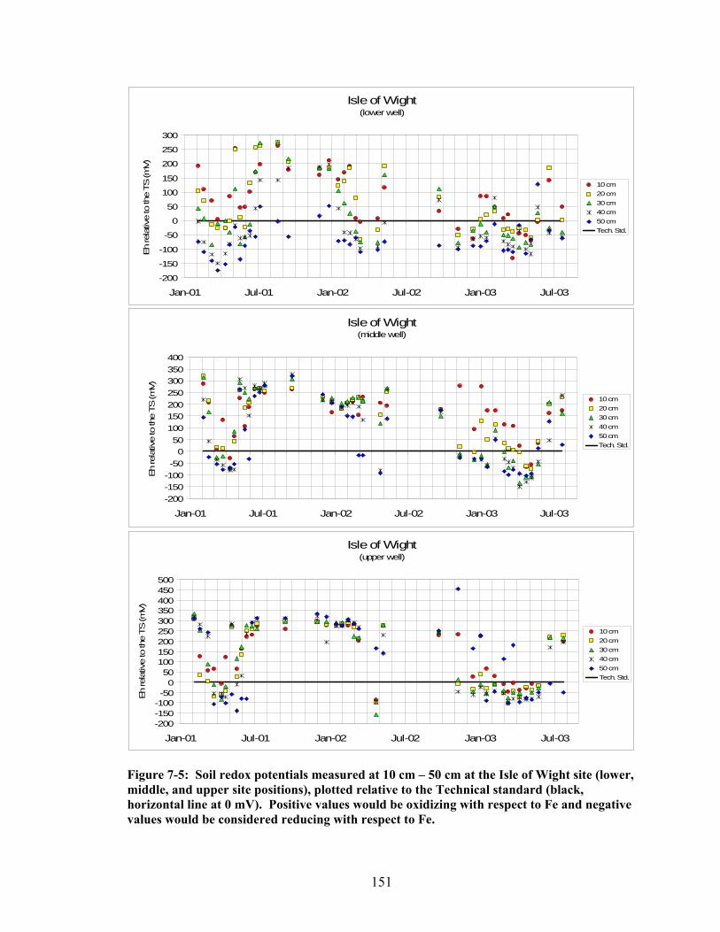
151
Figure 7-5: Soil redox potentials measured at 10 cm – 50 cm at the Isle of Wight site (lower, middle, and upper site positions), plotted relative to the Technical standard (black, horizontal line at 0 mV). Positive values would be oxidizing with respect to Fe and negative values would be considered reducing with respect to Fe.
Isle of Wight(lower well)
-200
-150
-100
-50
0
50
100
150
200
250
300
Jan-01 Jul-01 Jan-02 Jul-02 Jan-03 Jul-03
Eh
rela
tive
to th
e TS
(mV)
10 cm20 cm30 cm40 cm50 cmTech. Std.
Isle of Wight(middle well)
-200-150-100-50
050
100150200250300350400
Jan-01 Jul-01 Jan-02 Jul-02 Jan-03 Jul-03
Eh re
lativ
e to
the
TS (m
V)
10 cm20 cm30 cm40 cm50 cmTech. Std.
Isle of Wight (upper well)
-200-150-100-50
050
100150200250300350400450500
Jan-01 Jul-01 Jan-02 Jul-02 Jan-03 Jul-03
Eh
rela
tive
to th
e TS
(mV)
10 cm20 cm30 cm40 cm50 cmTech. Std.

152
Figure 7-6: Soil redox potentials measured at 10 cm – 50 cm at the Eastern Neck Island site (lower, middle, and upper site positions), plotted relative to the Technical standard (black, horizontal line at 0 mV). Positive values would be oxidizing with respect to Fe and negative values would be considered reducing with respect to Fe.
Eastern Neck Island (lower site)
-350-300-250-200-150-100-50
050
100150200250300350
Jan-01 Jul-01 Jan-02 Jul-02 Jan-03 Jul-03
Eh
rela
tive
to th
e TS
(mV)
10 cm20 cm30 cm40 cm50 cmTech. Std.
Eastern Neck Island(middle site)
-250-200-150-100-50
050
100150200250300350
Jan-01 Jul-01 Jan-02 Jul-02 Jan-03 Jul-03
Eh
rela
tive
to th
e TS
(mV)
10 cm20 cm30 cm40 cm50 cmTech. Std.
Eastern Neck Island (upper site)
-250-200-150-100-50
050
100150200250300350400
Jan-01 Jul-01 Jan-02 Jul-02 Jan-03 Jul-03
Eh
rela
tive
to th
e TS
(mV)
10 cm20 cm30 cm40 cm50 cmTech. Std.

153
Figure 7-7: Soil redox potentials measured at 10 cm – 50 cm at the Ted Harvey site (lower, middle, and upper site positions), plotted relative to the Technical standard (black, horizontal line at 0 mV). Positive values would be oxidizing with respect to Fe and negative values would be considered reducing with respect to Fe.
Ted Harvey (lower well)
-150-100-50
050
100150200250300350400450
Jan-01 Jul-01 Jan-02 Jul-02 Jan-03 Jul-03
Eh
rela
tive
to th
e TS
(mV)
10 cm20 cm30 cm40 cm50 cmTech. Std.
Ted Harvey (middle site)
-200-150-100-50
050
100150200250300350400450
Jan-01 Jul-01 Jan-02 Jul-02 Jan-03 Jul-03
Eh
rela
tive
to th
e TS
(mV)
10 cm20 cm30 cm40 cm50 cmTech. Std.
Ted Harvey (upper site)
-150-100-50
050
100150200250300350400450
Jan-01 Jul-01 Jan-02 Jul-02 Jan-03 Jul-03
Eh re
lativ
e to
the
TS (m
V)
10 cm20 cm30 cm40 cm50 cmTech. Std.

154
Precipitation
According to the TS, for a soil to be considered “hydric”, it must meet water table
and redox requirements during a period of “normal” precipitation. Rainfall is considered
to be “normal” when the quantity falls within the range of the 30th to the 70th percentiles
of the long-term local averages. For the ABLS-study, these statistics were available also
from the same stations that supplied monthly precipitation averages. The precipitation
data recorded at weather stations near to each of the research sites are illustrated in
Figures 7-8 through 7-11.
0
20
40
60
80
100
120
140
160
180
200
Jan-00 Apr-00 Jul-00 Oct-00 Jan-01 Apr-01 Jul-01 Oct-01 Jan-02 Apr-02 Jul-02 Oct-02 Jan-03 Apr-03 Jul-03 Oct-03 Jan-04
Pre
cipi
tatio
n (m
m)
BlackwaterWETS 70%WETS 30%
Figure 7-8: Precipitation data collected at Vienna, Md for the Blackwater site. The three-month running average of data is shown in reference to the 30th and 70th percentiles. The colored horizontal line along the bottom of the graph shows periods when the precipitation is above average (blue), average (green), and below average (red).

155
0
20
40
60
80
100
120
140
160
180
200
Jan-00 Apr-00 Jul-00 Oct-00 Jan-01 Apr-01 Jul-01 Oct-01 Jan-02 Apr-02 Jul-02 Oct-02 Jan-03 Apr-03 Jul-03 Oct-03 Jan-04
Pre
cipi
tatio
n (m
m)
Isle of WightWETS 70%WETS 30%
Figure 7-9: Precipitation data collected at the Ocean City Airport, Md for the Isle of Wight site. The three-month running average is shown in reference to the 30th and 70th percentiles. The colored horizontal line along the bottom of the graph shows periods when precipitation is above average (blue), average (green), and below average (red).
0
20
40
60
80
100
120
140
160
180
200
Jan-00 Apr-00 Jul-00 Oct-00 Jan-01 Apr-01 Jul-01 Oct-01 Jan-02 Apr-02 Jul-02 Oct-02 Jan-03 Apr-03 Jul-03 Oct-03 Jan-04
Pre
cipi
tatio
n (m
m)
Eastern NeckWETS 70%WETS 30%
Figure 7-10: Precipitation data collected at Chestertown, Md for the Eastern Neck Island site. The three-month running average is shown in reference to the 30th and 70th percentiles. The colored horizontal line along the bottom of the graph shows periods when precipitation is above average (blue), average (green), and below average (red).

156
0
20
40
60
80
100
120
140
160
180
200
Jan-00 Apr-00 Jul-00 Oct-00 Jan-01 Apr-01 Jul-01 Oct-01 Jan-02 Apr-02 Jul-02 Oct-02 Jan-03 Apr-03 Jul-03 Oct-03 Jan-04
Pre
cipi
tatio
n (m
m)
Ted HavryWETS 70%WETS 30%
Figure 7-11: Precipitation data collected at Dover, De for the Ted Harvey site. The three-month running average is shown in reference to the 30th and 70th percentiles. The colored horizontal line along the bottom of the graph shows periods when precipitation is above average (blue), average (green), and below average (red). Table 7-1: Amount of precipitation during the periods from November through May during three hydrological years. In general, the 2000-2001 period was normal (although it was dryer than normal at the IOW-site). The 2001-2002 period was dryer than normal at all sites, and the 2002-2003 period was wetter than normal at all sites.
Annual Wet Season
Site 11/2000 – 5/2001 11/2001 – 5/2002 11/2002 – 5/2003
Blackwater Normal Dry Wet Isle of Wight Dry Dry Slightly Wet Eastern Neck Normal Dry Wet
Ted Harvey Normal Dry Wet

157
Soil Saturation and Reduction
For a soil to be considered “hydric” by the TS, it must experience simultaneous
saturation and reduction for a period of at least 14 consecutive days. Figures 7-12
through 7-15 show the periods when water tables occurred at 20 cm and 30 cm below the
soil surface (thick, colored lines) and, also (at these depths), periods when soils were
reducing with respect to iron (thin, colored lines with markers). Water tables and reduced
conditions were then correlated to show periods when simultaneous saturation and
reduction occurred in the soil at 20 cm and 30 cm (thin, black lines). These data are
summarized in Table 7-2 showing the length individual events (days) when soils were
simultaneously saturated and reduced.

158
Dec-00 Mar-01 Jun-01 Sep-01 Dec-01 Mar-02 Jun-02 Sep-02 Dec-02 Mar-03 Jun-03 Sep-03
BWU20S+R
BWU_20R
BWU_20S
BWU30S+R
BWU_30R
BWU_30S
BWM20S+R
BWM_20R
BWM_20S
BWM30S+R
BWM_30R
BWM_30S
BWL20S+R
BWL_20R
BWL_20S
BWL30S+R
BWL_30R
BWL_30S
Upper Well
Lower Well
Middle Well
30 cm
20 cm
30 cm
20 cm
30 cm
20 cm
Figure 7-12: Periods when soils at the Blackwater site were saturated and reducing at depths of 20 cm and 30 cm. Thick, colored lines represent periods of saturation (S); thin, colored lines with markers represent reduced conditions (R); thin black lines represent periods of simultaneous saturation and reduction (S+R).

159
Dec-00 Mar-01 Jun-01 Sep-01 Dec-01 Mar-02 Jun-02 Sep-02 Dec-02 Mar-03 Jun-03 Sep-03
IOWU_20S+R
IOWU_20RIOWU_20S
IOWU_30S+RIOWU_30R
IOWU_30SIOWM_20S+R
IOWM_20RIOWM_20S
IOWM_30S+R
IOWM_30RIOWM_30S
IOWL_20S+RIOWL_20R
IOWL_20SIOWL_30S+R
IOWL_30RIOWL_30S
Upper Well
Lower Well
Middle Well
30 cm
20 cm
30 cm
20 cm
30 cm
20 cm
Figure 7-13: Periods when soils at the Isle of Wight site were saturated and reducing at depths of 20 cm and 30 cm. Thick, colored lines represent periods of saturation (S); thin, colored lines with markers represent reduced conditions (R); thin black lines represent periods of simultaneous saturation and reduction (S+R).
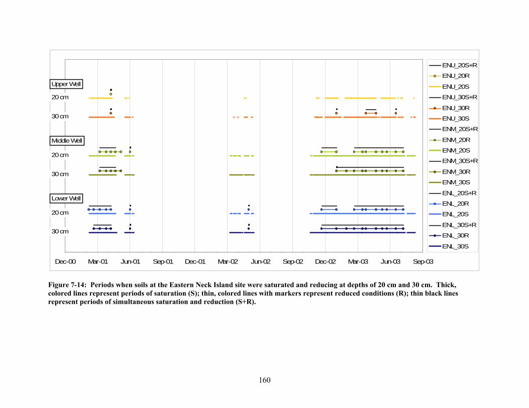
160
Dec-00 Mar-01 Jun-01 Sep-01 Dec-01 Mar-02 Jun-02 Sep-02 Dec-02 Mar-03 Jun-03 Sep-03
ENU_20S+R
ENU_20R
ENU_20S
ENU_30S+R
ENU_30R
ENU_30S
ENM_20S+R
ENM_20R
ENM_20S
ENM_30S+R
ENM_30R
ENM_30S
ENL_20S+R
ENL_20R
ENL_20S
ENL_30S+R
ENL_30R
ENL_30S
Upper Well
Lower Well
Middle Well
30 cm
20 cm
30 cm
20 cm
30 cm
20 cm
Figure 7-14: Periods when soils at the Eastern Neck Island site were saturated and reducing at depths of 20 cm and 30 cm. Thick, colored lines represent periods of saturation (S); thin, colored lines with markers represent reduced conditions (R); thin black lines represent periods of simultaneous saturation and reduction (S+R).
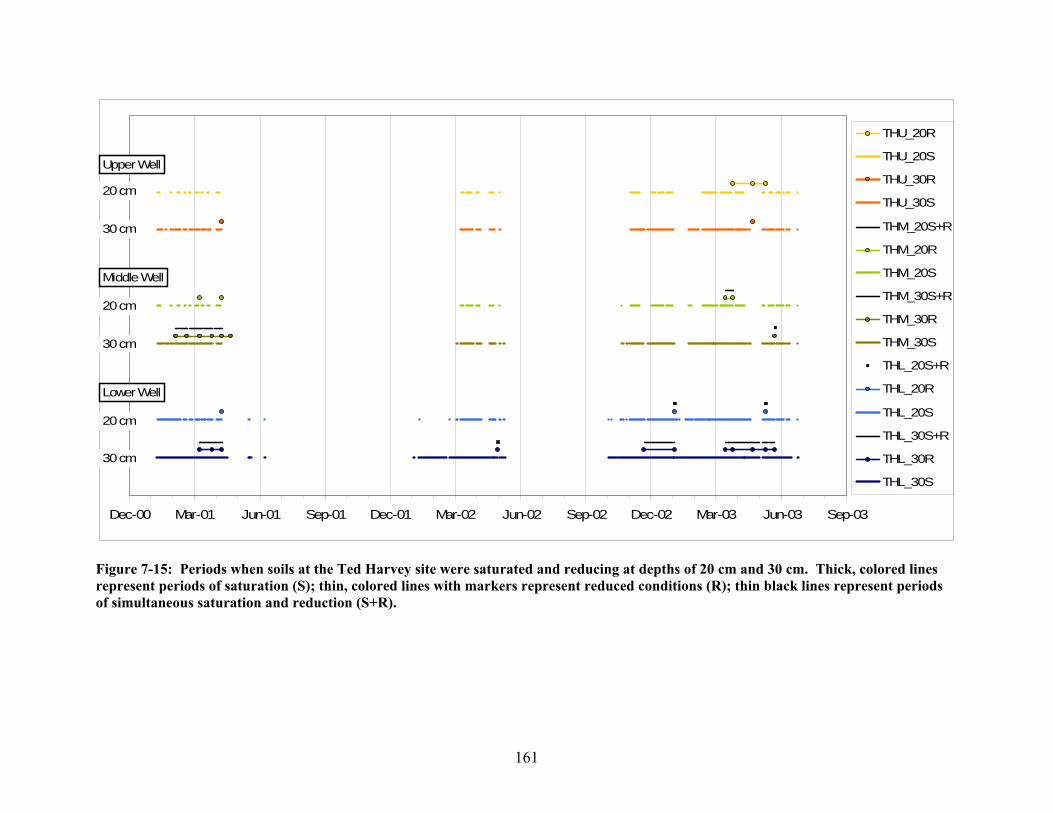
161
Dec-00 Mar-01 Jun-01 Sep-01 Dec-01 Mar-02 Jun-02 Sep-02 Dec-02 Mar-03 Jun-03 Sep-03
THU_20R
THU_20S
THU_30R
THU_30S
THM_20S+R
THM_20R
THM_20S
THM_30S+R
THM_30R
THM_30S
THL_20S+R
THL_20R
THL_20S
THL_30S+R
THL_30R
THL_30S
Upper Well
Lower Well
Middle Well
30 cm
20 cm
30 cm
20 cm
30 cm
20 cm
Figure 7-15: Periods when soils at the Ted Harvey site were saturated and reducing at depths of 20 cm and 30 cm. Thick, colored lines represent periods of saturation (S); thin, colored lines with markers represent reduced conditions (R); thin black lines represent periods of simultaneous saturation and reduction (S+R).

162
Table 7-2: Length of duration (days) of individual events when soils show simultaneous saturation and reduction at depths of 20 cm and 30 cm at the Blackwater, Isle of Wight, Eastern Neck Island, and Ted Harvey research sites. Numbers in bold indicate a period lasting for a minimum of 14 consecutive days. Paired numbers in italics represent a continuous episode of saturation across years. Site Position Lower Middle Upper Site Year 20 cm 30 cm 20 cm 30 cm 20 cm 30 cm Blackwater 2001 77 77 54 77 66 61 35 39 26 26 16 26 7 27 7 7 7 173 120 9 9 2002 144 144 15 144 7 15 55 7 44 80 80 80 80 80 80 2003 230 230 231 231 10 230 191 Isle of Wight 2001 45 45 7 35 26 30 7 14 6 2002 44 55 7 7 31 31 30 2003 5 39 7 40 32 163 70 70 7 82 94 9 16 7 28 22 7 Eastern Neck Island 2001 63 49 44 44 7 7 7 7 7 2002 7 7 30 30 30 2003 11 198 11 187 7 120 120 28 16 16 7 Ted Harvey 2001 32 17 32 10 2002 7 30 2003 7 11 11 7 7 48 17

163
Those soils that were shown to be simultaneously reducing and saturated for 14
days during a “normal” (or dry) year were identified as hydric, according to the TS. The
morphology of all soils was then evaluated to see whether or not they met a current FI.
This was compared with whether or not they were hydric according to the TS.
Of the twelve soils that were evaluated, three met one of the currently approved
Field Indicators of Hydric Soils. These soils were at the lower and middle positions of
the Blackwater site and at the lower position of the Ted Harvey site. The two soils at
Blackwater met the requirements of Field Indicator F3 (Depleted Matrix), and the one
soil at Ted Harvey met Field Indicator F6 (Redox Dark Surface). All three of these also
met the requirements of the TS. Of the remaining nine soils that did not meet one of the
approved Field Indicators, five soils were hydric based on the TS and four were not
hydric according to the TS (Tab. 7-3).
Table 7-3: Summary evaluations of soils at the study sites showing whether or not they are hydric soils according to the Technical Standard and whether or not they meet a currently approved Field Indicator for hydric soils. Labels in bold indicate where the soil was shown to be hydric according to the TS, but was lacking a currently approved FI.
Site Site Position Technical Standard
Currently Approved Field Indicator
Lower Hydric F3 (Depleted Matrix) Middle Hydric F3 (Depleted Matrix)
Blackwater
Upper Hydric X Lower Hydric X Middle NH X
Isle of Wight
Upper Hydric X Lower Hydric X Middle Hydric X
Eastern Neck Island
Upper NH X Lower Hydric F6 (Redox Dark Surface) Middle NH X
Ted Harvey
Upper NH X

164
Hydric ABLS-Soils
The morphology of hydric ABLS-soils on the Mid-Atlantic coastal plain was not
typical when compared to other soils that experienced similar wetness conditions. These
soils may be considered problematic in that they misrepresent their wetness status by
appearing (morphologically) as though water tables occurred lower in the soil profile.
Matrix colors in ABLS-soils were recorded as commonly having 2.5Y hues and chromas
of 3-5, depending on how wet the soils were. Pedons that experienced wetter conditions
were more likely to have a matrix color with chromas of 3 and 4; whereas those pedons
that experienced water tables lower in the profile, had chroma colors greater than 4
(complete soil descriptions are listed in chapter 4: “Relationship of Soil Morphology and
Water Tables”).
In examining these five soils that were hydric according to the TS, but did not
meet a FI, it was noted that, in general, they had an abundance of redox concentrations in
the upper part, but typically had brighter matrix colors of chroma 4. By carefully
comparing the morphology and distinguishing between those soils that were, or were not
hydric according to the TS, we were able to formulate a draft Field Indicator.
The proposed indicator requires the soils to have a mineral layer at least 10 cm (4
inches) thick starting within 20 cm (8 inches) of the soil surface with matrix (60 percent
or more of the volume) chroma of less than 5 and 10 percent or more distinct or
prominent redox concentrations occurring as soft masses or pore linings and/or
depletions. When this draft indicator was initially applied to these five hydric ABLS-
soils that were missed by the current Indicators, the proposed indicator captured all five
as hydric. In addition, when compared with the four pedons that were not hydric

165
according to the TS, none of the soils met the proposed indicator. Evaluation of ABLS-
soils using the Technical Standard criteria, the currently approved Field Indicators of
Hydric Soils, and the proposed indicator for ABLS-soils, the proposed indicator captured
(as hydric) all five of those soils that met the TS, but none of the fours soils that did not
meet the TS. Therefore, this proposed indicator was found to be “proof-positive”, as is
required of all Indicators (Tab. 7-4).
Table 7-4: Evaluation of 12 soils in the ABLS-study using the proposed Field Indicator for ABLS-soils. All five of the hydric soils (according to the TS) that did not meet an approved FI, were identified with the proposed FI. None of the four non-hydric soils were identified using the proposed indicator. NH= not hydric; X=does not meet indicator. Technical Currently Approved Proposed Site Site Position Standard Indicator Indicator
Lower Hydric F3 (Depleted Matrix) Hydric Middle Hydric F3 (Depleted Matrix) X
Blackwater
Upper Hydric X Hydric
Lower Hydric X Hydric Middle NH X X
Isle of Wight
Upper Hydric X Hydric
Lower Hydric X Hydric Middle Hydric X Hydric
Eastern Neck Island
Upper NH X X
Lower Hydric F6 (Redox Dark Surface) Hydric Middle NH X X
Ted Harvey
Upper NH X X

166
EPILOGUE
The data and draft indicator that were presented in this paper were submitted to
the National Technical Committee on Hydric Soils (NTCHS) for review early in 2005.
Following the review, the NTCHS approved this proposed Field Indicator in January of
2006 as a new Field Indicator of Hydric Soils (USDA-NRCS, 2006). This new Field
Indicator is identified as “F20: Anomalous Bright Loamy Soils”. Soils that are identified
as hydric using the F20 Indicator are common to landscapes that are linear to slightly
convex, occurring within 200 meters from estuarine marshes or waters, and within 1
meter of mean high water. The F20 Indicator for identifying hydric ABLS-soils was
approved for use in Major Land Resource Area (MLRA) 149A of Land Resource Region
(LRR) S and MLRAs 153C and 153D of LRR T; and for testing in MLRA 153B in LRR
T.

167
8) Thesis Conclusions
Water tables that come close to the soil surface for extended periods of time affect
the biogeochemistry of the soil. The stability and solubility of soil minerals such as
manganese and iron are determined by the redox potentials that develop under saturated
and reduced conditions. According to the Technical Standard of the NTCHS, on average
ABLS-soils developed reducing conditions sufficient to reduce iron after 43 days of
continuous saturation. It was also shown that the rate at which saturated ABLS-soils
develop reducing conditions is a function of soil temperature and thus could be as short
as 18 days (at approximately 19°C) or as long as 123 days (at approximately 4°C).
Research conducted on the Delmarva Peninsula proved that ABLS-soils were
simultaneously saturated and reduced, yet did not develop redoximorphic features
consistent with their saturation. No distinct or prominent redoximorphic features were
described in horizons that were saturated for less than 22% of the three-year study period.
For iron concentrations to form in horizons without 2-chroma depletions, an average
saturation of 54% (ranging from 22 to 82%) was required. Iron depletions formed in
horizons that were saturated for an average of 78% (ranging from 41 to 100%), while
depleted matrices developed only when saturation rates averaged 96% (ranging from 82
to 100%). Comparing these result to those of similar studies in other pedological
settings, ABLS-soils required significantly longer saturation periods to develop
comparable redoximorphic features. Only the study conducted by Castenson (2004),
investigating the problematic Piedmont floodplain soils, reported similar results.
Four research sites on the Delmarva Peninsula, representing ABLS-soils, showed
that soils were saturated at 30 cm for between 17 weeks (Ted Harvey site – upper soil)

168
and 49 weeks (Blackwater site – lower soil) out of the year. During these periods of
saturation, redox potentials were sufficiently low to develop anaerobic and reducing
conditions to reduce ferric to ferrous iron. Because the observed soil morphology was
inconsistent with the degree of wetness they experienced, the propensity of these soils to
form redoximorphic features was investigated in the lab. Measured CCPI values were
shown to range from 53 to 141, with a mean of 71, which demonstrated that these soils
were within the “non-problematic” range of the CCPI-scale. Therefore, the soil parent
material was ruled out as a significant factor in causing the soils to show uncharacteristic
hydromorphology.
To determine whether hydrological flow and limits to leaching of reduced iron
might be a determining factor contributing to the ABLS-phenomenon, soil cores from the
Isle of Wight site were leached under continuously saturated and reduced conditions in
the lab. An average of 3.92 g of iron was leached from the control cores, while the cores
treated with dextrose and the cores treated with leaves lost an average of 2.18 g and 5.30
g of iron, respectively. The addition of ground leaves resulted in increased Fe-leaching.
It was surprising, however, that the cores treated with dextrose had notably lower
leaching rates of Fe compared to the leached control group. It was unclear what caused
this; however speculations have been made relating these results to the effects of dextrose
on anaerobic bacterial populations. After approximately six months of leaching, distinct
changes in matrix colors were observed in all cores regardless of treatment. Matrix
chroma colors changed from 2.5Y 5/4 to 2.5Y 5/3+, while matrix hues and values
essentially remained unaffected. The continual leaching iron from all cores appeared to
have no influence on either the formation or removal of redoximorphic features that were

169
present. Results of this leaching experiment suggest that the explanation of the ABLS-
phenomenon may be related to a low, lateral hydrologic gradient that inhibits soluble,
reduced Fe from being moved out of the system and is instead allowed to re-oxidize, in-
situ. An alternate, actually related explanation for this phenomenon may be that these
soils have not experienced saturated and reducing conditions long enough (years/decades)
for the morphology to reflect that of a hydric soil.
Anomalous Bright Loamy Soils on the Delmarva Peninsula represent a group of
soils found in a distinctive, pedological setting in the Mid-Atlantic coastal plain. Many
of these soils are saturated and reducing, and therefore would be considered hydric by the
Technical Standard, yet they do not meet any of the Field Indicators of Hydric Soils
(USDA-NRCS, 2002). A proposed Field Indicator was developed to assist in identifying
these unusual hydric soils. This Indicator requires a mineral layer at least 10 cm (4
inches) thick starting within 20 cm (8 inches) of the soil surface with matrix (60 percent)
or more of the volume) chroma of less than 5 and 10 percent or more distinct or
prominent redox concentrations occurring as soft masses or pore linings and/or
depletions. This indicator identified five ABLS-soils as hydric that were previously
missed because of a lacking Indicator and succeeded in discriminating against four soils
that did not meet the TS. Based on the work presented in this thesis, the National
Technical Committee on Hydric Soils (NTCHS) approved this proposed Field Indicator,
which was accepted in January of 2006. The Field Indicator is identified as “F20:
Anomalous Bright Loamy Soils”.

170
Appendix A: Soil Descriptions Soil Description: Blackwater National Wildlife Refuge, Dorchester County, MD Site Position: Lower Well Coordinates: Date; Time: August 21, 2002; 9:00 am Water Table Height (pit or open auger hole): 37 cm Pit Depth: 0-105 cm Auger Depth: none Described by: Philip Zurheide and John Wah NOTES: Some mixing of A into E horizon (root mat lenses); redox in 5th horizon shows sharper boundaries than in horizon above. Horizon Depth
(cm) Description
Oe 14-0 dark reddish brown (5YR 2.5/2) mucky peat; clear smooth boundary. A 0-7 black (7.5YR 2.5/1) mucky silt loam (11% clay); weak medium sub-angular blocky structure; very friable; abrupt wavy
boundary. Eg 7-16 gray (2.5Y 6/1) silt loam (14% clay) with common (15%) medium distinct olive (5Y 5/3) and common (3%) fine prominent
yellowish brown (10YR 5/6) soft masses; moderate medium sub-angular blocky parting to weak medium platy structure; friable; clear smooth boundary.
BEg 16-26 gray (2.5Y 6/1) silt loam (15% clay) with many (34%) medium distinct light olive brown (2.5Y 5/6) and common (15%)
medium prominent yellowish brown (10YR 5/6) and few (1%) fine prominent yellowish brown (10YR 5/8) soft masses; weak medium sub-angular blocky structure; friable; clear smooth boundary.
Btg1 26-39 gray (2.5Y 6/1) silt loam (21% clay) with common (13%) medium distinct light olive brown (2.5Y 5/6) and common (18%)
medium prominent yellowish brown (10YR 5/8) soft masses; weak coarse sub-angular blocky structure; friable; clear smooth boundary.
Btg2 39-53 gray (N5) silt loam (25% clay) with common (17%) medium prominent yellowish brown (10YR 5/8) soft masses; weak coarse
sub-angular blocky structure; friable; clear smooth boundary.

171
Bt1 53-66 yellowish brown (10YR 5/6) with many (21%) medium distinct strong brown (7.5YR 5/8) soft masses and common (5%) fine to medium distinct yellowish red (5YR 5/6) as clay skins and many (25%) medium prominent gray (5Y 5/1) iron depletions; weak coarse prismatic parting to moderate medium to thick platy structure; friable; clear smooth boundary.
Bt2 66-77 olive (5Y 5/4) loam (26% clay) with common (13%) fine to medium prominent strong brown (7.5YR 5/8) soft masses with
common (7%) medium prominent and fine to medium distinct yellowish red (5YR 5/6) as clay skins and common (10%) medium faint olive gray (5Y 5/2) and common (15%) medium distinct gray (N5) iron depletions; weak coarse prismatic parting to moderate medium thick platy structure; friable (brittle); clear smooth boundary.
2BC 77-91 light olive brown (2.5Y 5/4) sandy loam (13% clay) with common 15%) medium to coarse prominent yellowish brown (10YR
5/8) and common (15%) fine to medium prominent strong brown (7.5YR 5/8) soft masses and common (18%) medium prominent grayish brown (2.5Y 5/2) iron depletions; weak to moderate thick platy and weak coarse prismatic structure; friable.

172
Soil Description: Blackwater National Wildlife Refuge, Dorchester County, MD Site Position: Middle Well Date; Time: Jan 24, 2002; 9:00 am Water Table Height (pit or open auger hole): N/A Pit Depth: 0-114 cm Auger Depth: 114 cm - 140+ cm Described by: Martin C. Rabenhorst and Phillip King; assisted by Philip Zurheide, Carla Baker, Steve Burch, Charlie Hanner, John Wah, and David Win. NOTES: No iron concentrations in A horizon; Redox depletions pronounced around decaying roots/channels and along prism faces. Horizon Depth
(cm) Description
Oe 11-0 very dusky red (2.5YR 2.5/2) mucky peat; abrupt smooth boundary. A 0-10 dark reddish gray to weak red (2.5YR 4/1.5) silt loam (11% clay); weak medium sub-angular blocky structure; friable;
abrupt smooth boundary. Bt (BE) 10-22 light olive brown (2.5Y 5/6) (40%) and olive yellow (2.5Y 6/6) (40%) silt loam (21% clay) with common (2%) very fine
prominent strong brown (7.5YR 4/6) and common (2%) yellowish brown (10YR 5/6) soft masses and common (16%) medium distinct gray (2.5Y 6/1) iron depletions; weak medium sub-angular blocky structure parting to weak fine sub-angular blocky structure; friable; clear smooth boundary.
Btg 22-51 gray (5Y 6/1) (70%) and light brownish gray (2.5Y 6/2) (10%) silty clay loam (31% clay) with common (20%) medium
distinct reddish yellow (7.5YR 6.5/8) soft masses; weak medium sub-angular blocky structure; friable; clear smooth boundary.
2Bt 51-103 light olive brown (2.5Y 5/6) (25%) and yellowish brown (10YR 5/8) (50%) loam to sandy clay loam (21% clay) to fine
sandy loam with common (5%) reddish yellow (7.5YR 6.5/8) soft masses and common (20%) greenish gray (10Y 6/1) and gray (N5) iron depletions; weak very coarse prismatic parting to moderate medium platy parting to moderate fine to medium sub-angular blocky structure; firm; clear smooth boundary.
2BC 103-129 yellowish brown (10YR 5/6) sandy loam with common medium distinct reddish yellow (7.5YR 6/8) soft masses. 2C 129+ light olive brown (2.5Y 5/4) fine sandy loam.

173
Soil Description: Blackwater National Wildlife Refuge, Dorchester County, MD Site Position: Upper Well Date; Time: Jan 24, 2002; 12:00 pm Water Table Height (pit or open auger hole): N/A Pit Depth: 0-88 cm Auger Depth: 88 cm - 212 cm Described by: Martin C. Rabenhorst and Phillip King; assisted by Philip Zurheide, Carla Baker, Steve Burch, Charlie Hanner, John Wah, and David Win. NOTES: Redox depletions pronounced around decaying roots/channels and along prism faces. Horizon Depth
(cm) Description
Oe 5-0 black (5YR 2.5/1) mucky peat; abrupt smooth boundary. A 0-10 very dark grayish brown to dark grayish brown (10YR 3.5/2) (97%) silt loam (9% clay) with common (3%) fine dark brown
(7.5YR 3/3) soft masses around roots; weak medium subangular blocky structure; friable; clear smooth boundary. EA 10-16 dark grayish brown to olive brown (2.5Y 4/2.7) (93%) silt loam (9% clay) with common (7%) fine dark brown (7.5YR 3/3)
soft masses; weak fine to medium subangular blocky structure; friable; abrupt smooth boundary. Bt1 16-33 light olive brown (2.5Y 5/4) (80%) silt loam (17.5% clay) with common (7%) strong brown (7.5YR 4/6) and common (3%)
dark brown (7.5YR 3/4) soft masses and common (5%) light olive brown (2.5Y 5/3.2) and common (5%) light brownish gray (2.5Y 6/2) iron depletions; weak medium subangular blocky structure; friable; clear to gradual smooth boundary.
Bt2 33-63 light olive brown (2.5Y 5/4) (65%) loam (23% clay) with common (10%) fine strong brown (7.5YR 4/6) soft masses and
common (10%) light olive brown (2.5Y 5/3) and common (15%) grayish brown (2.5Y 5/2) iron depletions; weak fine subangular blocky structure; friable; clear smooth boundary.
2BC1 63-83 yellowish brown (10YR 5/6) (65%) sandy loam (15% clay) with many (25%) medium faint dark yellowish brown (10YR 4/6)
soft masses and common (10%) grayish brown (2.5Y 5/2) iron depletions; weak medium platy parting to weak medium subangular blocky structure; friable; clear smooth boundary.
2BC2 83-173 Yellowish brown (10YR 5/6) loamy sand with strong brown (7.5YR 4/6) soft masses and light brownish gray (2.5Y 6/2) iron
depletions.

174
2BC3 173-
207 yellowish brown (10YR 5/4) sandy loam with strong brown (7.5YR 4/6) soft masses and gray (2.5Y 6/1) iron depletions.

175
Soil Description: Isle of Wight Wildlife Management Area, Worcester County, MD Site Position: Lower Well Date; Time: July 22, 2002; 1:00 pm Water Table Height (pit or open auger hole): N/A Pit Depth: 0-96+ cm Auger Depth: N/A Described by: Martin C. Rabenhorst and Philip Zurheide, assisted by Steve Burch, Karen Castenson, Cary Coppock, and Robert Vaughan NOTES: Horizon Depth
(cm) Description
Oe 6-0 very dusky red (2.5YR 2.5/2) mucky peat; abrupt smooth boundary. A 0-9 very dark gray (2.5Y 3/1) (92%) sandy loam to loam (8% clay) with common (8%) distinct fine dark reddish brown (5YR 3/3)
pore linings of iron; weak fine sub-angular blocky structure; friable; clear wavy boundary. B/A 9-27 light olive brown (2.5Y 5/4) (60%) and very dark grayish brown to dark grayish brown (2.5Y 3.5/2) (15%) sandy loam (14%
clay) with common (15%) medium distinct strong brown (7.5YR 4/6) soft masses and pore linings of iron and common (5%) fine prominent yellowish red (5YR 4/6) pore linings of iron and common (5%) medium to coarse faint very dark grayish brown to dark grayish brown (2.5Y 3.5/2) iron depletions; moderate medium sub-angular blocky structure; friable; clear smooth boundary.
Bt1 27-45 light olive brown (2.5Y 5/4) loam (18% clay) with many (25%) medium distinct strong brown (7.5YR 4/6) soft masses and
pore linings of iron and common (5%) fine prominent yellowish red (5YR 4/6) pore linings of iron and common (5%) medium to coarse faint grayish brown (2.5Y 5/2) iron depletions; moderate medium sub-angular blocky structure; friable; clear smooth boundary.
Bt2 45-60 dark yellowish brown (10YR 4/4) fine sandy loam (15% clay) with common (20%) medium to coarse faint strong brown
(7.5YR 5/6) soft masses of iron and common (5%) fine distinct strong brown (7.5YR 4/6) pore linings of iron and common (5%) moderate to coarse gray (2.5Y 5/1) iron depletions; weak moderate to coarse sub-angular blocky structure; friable; clear smooth boundary.
BC 60-
90+ light olive brown (2.5Y 5/4) loamy sand (6% clay) with common (20%) very coarse prominent yellowish brown (10YR 5/6) soft masses of iron and common (5%) medium to coarse prominent yellowish red (5YR 4/6) pore linings of iron and common

176
(20%) very coarse faint dark grayish brown (2.5Y 5/2) iron depletions; structureless massive; very friable.

177
Soil Description: Isle of Wight Wildlife Management Area, Worcester County, MD Site Position: Middle Well Date; Time: July 22, 2002; 1:00 pm Water Table Height (pit or open auger hole): N/A Pit Depth: 0-96+ cm Auger Depth: N/A Described by: Martin C. Rabenhorst and Philip Zurheide, assisted by Steve Burch, Karen Castenson, Cary Coppock, and Robert Vaughan Horizon Depth
(cm) Description
A 0-9 very dark brown (7.5YR 2.5/2) loam to sandy loam (10% clay) with few (1%) fine distinct dark reddish brown (5YR 5/4) pore linings of iron; moderate medium granular structure; very friable; clear smooth boundary.
AE 9-20 olive brown (2.5Y 4/4) loam to fine sandy loam (11% clay) with common (4%) fine to medium distinct yellowish red (5YR
4/6) pore linings of iron; weak fine sub-angular blocky parting to weak fine to medium granular structure; friable; clear smooth boundary.
EB 20-33 yellowish brown (10YR 5/6) sandy loam (9% clay) with common (6%) fine to medium distinct yellowish red (5YR 4/6) pore
linings of iron and common (5%) medium to coarse faint light olive brown (2.5Y 5/4) iron depletions; weak medium sub-angular blocky structure; friable; clear smooth boundary.
Bt1 33-49 dark yellowish brown (10YR 4/6) sandy loam (16% clay) with common (5%) fine distinct yellowish red (5YR 5/8) pore
linings of iron and common (15%) medium to coarse distinct light olive brown (2.5Y 5/3) iron depletions; moderate medium to coarse sub-angular blocky structure; friable; clear smooth boundary.
Bt2 49-70 dark yellowish brown (10YR 4/6) sandy loam (19% clay) with common (10%) coarse distinct strong brown (7.5YR 4/6) soft
masses of iron and common (2%) fine prominent yellowish red (5YR 5/8) pore linings of iron and light olive brown (2.5Y 5/3) iron depletions; moderate medium to coarse sub-angular blocky structure; friable; clear smooth boundary.
C1 70-89 yellowish brown (10YR 5/4) sandy loam to loamy sand (8% clay) with common (20%) coarse to very coarse faint yellowish
brown (10YR 5/6) soft masses of iron and common (3%) fine to medium prominent yellowish red (5YR 5/8) pore linings of iron and common (5%) medium to coarse faint light yellowish brown (2.5Y 6/4) iron depletions; very weak coarse sub-angular blocky structure; very friable; gradual smooth boundary.
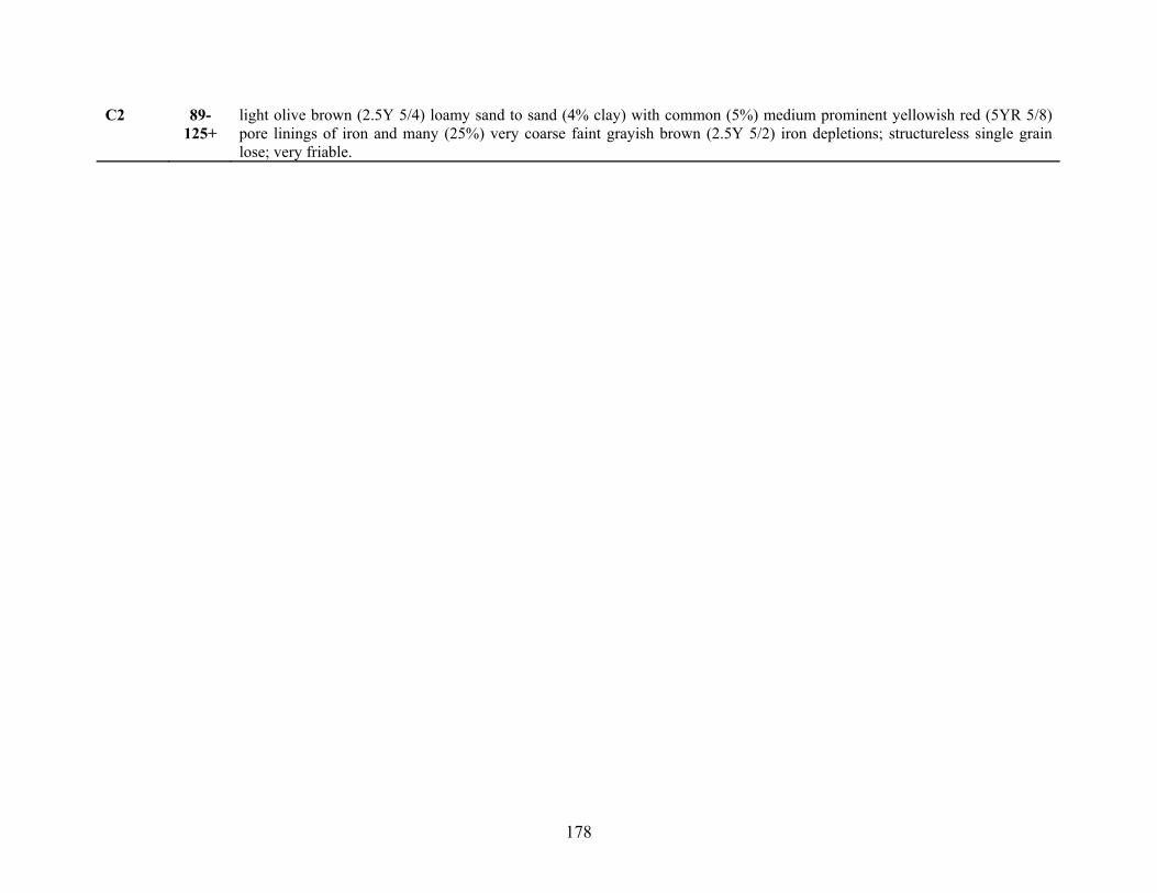
178
C2 89-125+
light olive brown (2.5Y 5/4) loamy sand to sand (4% clay) with common (5%) medium prominent yellowish red (5YR 5/8) pore linings of iron and many (25%) very coarse faint grayish brown (2.5Y 5/2) iron depletions; structureless single grain lose; very friable.

179
Soil Description: Isle of Wight Wildlife Management Area, Worcester County, MD Site Position: Upper Well Date; Time: July 22, 2002; 1:00 pm Water Table Height (pit or open auger hole): N/A Pit Depth: 0-96+ cm Auger Depth: N/A Described by: Martin C. Rabenhorst and Philip Zurheide, assisted by Steve Burch, Karen Castenson, Cary Coppock, and Robert Vaughan Horizon Depth
(cm) Description
A 0-10 dark brown (7.5YR 3/2) loam to fine sandy loam (10% clay); moderate medium granular structure; friable; abrupt wavy boundary.
AB 10-18 brown (10YR 4/3) fine sandy loam (12% clay) with common (10%) medium distinct strong brown (7.5YR 4/6) and common
(5%) medium prominent dark reddish brown (5YR 3/4) soft masses of iron and common (3%) fine dark grayish brown (2.5Y 4/2) iron depletions; weak medium sub-angular blocky structure; friable; clear wavy boundary.
BA 18-31 light olive brown (2.5Y 5/4) fine sandy loam (13% clay) with many (35%) medium to coarse faint yellowish brown (10YR
5/6) soft masses of iron and common (3%) fine distinct strong brown (7.5YR 4/6) pore linings of iron; weak medium sub-angular blocky structure; friable; clear smooth boundary.
Bt1 31-55 yellowish brown (10YR 5/6) fine sandy loam (14% clay) with common (2%) fine prominent strong brown (7.5YR 5/8) pore
linings of iron and common (8%) coarse distinct light olive brown (2.5Y 5/3) iron depletions around roots and common (10%) medium to coarse faint light olive brown (2.5Y 5/4) iron depletions; weak coarse sub-angular blocky structure; friable; clear smooth boundary. yellowish brown (10YR 5/6) sandy loam (11% clay) with common (15%) medium distinct strong brown (7.5YR 4/6) soft masses and pore linings of iron and common (15%) medium to coarse distinct light yellowish brown (2.5Y 6/4) iron depletions; weak medium to coarse sub-angular blocky structure; friable; clear smooth boundary.
Bt2 55-77 yellowish brown (10YR 5/6) sandy loam (11% clay) with common (15%) medium distinct strong brown (7.5YR 4/6) soft
masses and pore linings of iron and common (15%) medium to coarse distinct light yellowish brown (2.5Y 6/4) iron depletions; weak medium to coarse sub-angular blocky structure; friable; clear smooth boundary.
BC 77-90 brownish yellow (10YR 6/6) loamy sand (6% clay) with common (20%) medium to coarse distinct strong brown (7.5YR 4/6)
soft masses of iron and common (3%) fine distinct strong brown (7.5YR 5/8) pore linings of iron and many (25%) coarse to

180
very coarse distinct light yellowish brown (2.5Y 6/4) iron depletions; very weak medium to coarse sub-angular blocky structure; very friable; clear smooth boundary.
C1 90-137 light olive brown (2.5Y 5/3) sand (4% clay) with common (15%) fine to medium prominent strong brown (7.5YR 5/8) pore
linings of iron and common (10%) coarse to very coarse distinct light olive brown (2.5Y 5/6) soft masses of iron and many (30%) coarse to very coarse faint light brownish gray (2.5Y 6/2) iron depletions; structureless single grain lose; very friable; clear wavy boundary.
C2 137-
150 gray (2.5Y 6/1) (30%) and yellowish brown (10YR 5/4) (60%) fine sand to loamy fine sand with common (10%) medium to coarse distinct strong brown (7.5YR 4/6) soft masses of iron.
2Cg 150-
183 gray (5Y 6/1) fine sandy loam (14% clay) with many (30%) coarse to very coarse prominent yellowish brown (10YR 5/6) and common (10%) medium to coarse prominent strong brown (7.5YR 5/8) soft masses of iron.
3C’1 183-
225 light olive brown (2.5Y 5/3) loam (26% clay) with common (15%) medium prominent strong brown (7.5YR 4/6) and common (5%) medium prominent strong brown (7.5YR 5/8) and common (5%) fine to medium prominent dusky red (2.5YR 3/2) soft masses of iron and many (30%) medium to very coarse prominent gray (5Y 6/1) iron depletions; firm.
4C’2 225-
259 light olive brown (2.5Y 5/3) fine sandy loam (10% clay) with common (10%) coarse prominent strong brown (7.5YR 4/6) and common (20%) very coarse prominent strong brown (7.5YR 5/8) soft masses of iron.
5C’3 259-
270+ dark yellowish brown (10YR 4/4) fine sand with many (25%) very coarse prominent strong brown (7.5YR 4/6) soft masses of iron.

181
Soil Description: Eastern Neck Island National Wildlife Refuge, Kent County, MD Site Position: Lower Well Date; Time: November 28, 2001; 9:00 am Water Table Height (pit or open auger hole): N/A Pit Depth: 0-170 cm Auger Depth: 170 cm – 310 cm Described by: Martin C. Rabenhorst, Phillip King, and Philip Zurheide, and assisted by John Wah, Steve Burch, and Suzy Park. Horizon Depth
(cm) Description
Oe 3-2 dark brown (7.5YR 3/2) mucky peat; abrupt smooth boundary. A 0-6 very dark gray (10YR 3/1) silt loam (8% clay); moderate fine to medium granular structure; friable; common (10%) fine to
medium roots; abrupt smooth boundary. EA 6-15 brown (10YR 4/3) silt loam (10% clay) with few (1%) strong brown (7.5YR 4/6) soft masses; moderate very fine sub-angular
blocky structure; friable; common (10%) fine to medium roots; clear wavy boundary. BE 15-32 light yellowish brown (2.5Y 6/4) (40%) and (2.5Y 6/3) (25%) silt loam (13% clay) with common (5-10%) yellowish brown
(10YR 5/8) and common (10%) dark yellowish brown (10YR 4/6) soft masses and many (25%) light yellowish brown (2.5Y 6/3) iron depletions; weak course sub-angular blocky structure; friable to firm (brittle); common (5%) fine roots; clear smooth boundary.
Bt1 32-42 pale brown (10YR 6/3) silt loam (19% clay) with common (5%) dark reddish brown (5YR 3/4) soft masses and many (30%)
yellowish brown (10YR 5/6) iron depletions; weak course platy and moderate fine to medium sub-angular blocky structure; friable; common (5-10%) fine to medium roots; clear smooth boundary.
Bt2 42-62 yellowish brown (10YR 5/8) loam (22% clay) with many (25%) strong brown (7.5YR 5/6) and common (5%) dark reddish
brown (5YR 3/4) soft masses and many (30%) pale brown (10YR 6/3) iron depletions; weak course platy and moderate fine to medium sub-angular blocky structure; friable; common (6%) fine to medium roots; clear smooth boundary.
2Bt 62-77 yellowish brown (10YR 5/6) very fine sandy loam/loam (19% clay) with many (25%) strong brown (7.5YR 5/6) soft masses
and common (15%) light brownish gray (2.5Y 6/2) and many (25%) light yellowish brown (2.5Y 6/4) iron depletions; weak very coarse prismatic and moderate medium to course platy and moderate fine to medium sub-angular blocky structure;

182
friable to firm (slightly brittle); few fine to medium roots; clear smooth boundary. 2BC1 77-112 yellowish brown (10YR 5/4) fine sandy loam (19% clay) with many (25%) strong brown (7.5YR 4/6) soft masses and
common (10%) gray (2.5Y 6/1) iron depletions in areas of loamy fine sand and common (20%) light yellowish brown (2.5Y 6/4) mottles; weak to moderate very course prismatic and moderate to strong course platy structure; friable; very few fine roots; clear smooth boundary.
2BC2 112-
143 light olive brown (2.5Y 5/6) fine sandy loam (16% clay) with common (20%) yellowish brown (10YR 5/6) soft masses and common (20%) yellowish brown (2.5Y 6/4) and common (10%) gray (2.5Y 6/1) iron depletions; strong very course sub-angular blocky structure; friable; gradual smooth boundary.
2BC3 143-
167 yellowish brown (10YR 5/6) fine sandy loam (14% clay) with common (10%) strong brown (7.5YR 5/6) soft masses and many (25%) greenish gray (10Y 6/1) iron depletions; strong very course sub-angular blocky structure; friable; clear smooth boundary.
2BC4 167-
179 light gray (2.5Y 7/1) fine sandy loam (7% clay) with common (10%) light yellowish brown (2.5YR 6/3) and common (20%) reddish yellow (7.5YR 6/8) soft masses.
2C1 179-
199 light olive brown (2.5Y 5/3-4) fine sandy loam (12% clay) with common (20%) red (2.5YR 4/6) soft masses and common (5%) gray (2.5Y 6/1) iron depletions.
2C2 199-
215 light gray (2.5Y 7/1) fine sandy loam (9% clay) with common (5%) yellowish brown (10YR 5/6) soft masses and many (40%) light yellowish brown (2.5Y 6/3) iron depletions.
2C3 215-
257 light olive brown (2.5Y 5/3) very fine sandy loam (6% clay) with common (7%) strong brown (7.5YR 5/6) soft masses and common (5%) light gray (2.5Y 7/1) iron depletions.
2C4 257-307
light olive brown (2.5Y 5/4) very fine sandy loam (9% clay) with common (10%) strong brown (7.5 YR 5/6) soft masses.

183
Soil Description: Eastern Neck Island National Wildlife Refuge, Kent County, MD Site Position: Middle Well Date; Time: November 28, 2001; 9:00 am Water Table Height (pit or open auger hole): N/A Pit Depth: 0-150 cm Auger Depth: 150 cm – 240 cm Described by: Martin C. Rabenhorst, Phillip King, and Philip Zurheide, and assisted by John Wah, Steve Burch, and Suzy Park. Horizon Depth
(cm) Description
Oe 3-0 mucky peat; abrupt smooth boundary. A 0-9 very dark gray (10YR 3/1) silt loam (8% clay); moderate fine to medium granular structure; very friable; clear wavy
boundary; common fine to medium roots. AE 9-15 brown (10YR 4/3) silt loam (10% clay); moderate fine to medium sub-angular blocky structure; very friable; clear wavy
boundary; common fine to medium roots. BE 15-28 light yellowish brown (2.5Y 6/4) silt loam (14% clay) with many (30%) yellowish brown (10YR 5/6) soft masses of iron;
weak medium to coarse sub-angular blocky structure; friable; clear smooth boundary; common fine to medium roots. Bt1 28-45 strong brown (7.5YR 5/6) silt loam (21% clay) with many (30%) yellowish brown (10YR 5/8) soft masses of iron and
common (20%) light yellowish brown (2.5Y 6/4) and common (10%) light yellowish brown (2.5Y 6/3) iron depletions; moderate fine to medium sub-angular blocky structure; friable; clear smooth boundary; common fine to medium roots.
Bt2 45-69 light brown (7.5YR 6/4) (30%) and yellowish brown (10YR 5/6) (30%) loam (18% clay) with many (25%) strong brown
(7.5YR 5/8) soft masses of iron and common (5%) brown (10YR 5/3) and common (10%) light gray (2.5Y 7/2) iron depletions; moderate medium to coarse sub-angular blocky structure; friable gradual smooth boundary; common medium roots.
2Bt3 69-92 yellowish brown (10YR 5/6) fine sandy loam (15% clay) with common (5%) yellowish red (5YR 4/6) and many (25%) strong
brown (7.5YR 5/8) and many (30%) light yellowish brown (2.5Y 6/4) soft masses of iron and light brownish gray (2.5Y 6/2) and light brownish gray (10YR 6/2) iron depletions; moderate coarse sub-angular blocky with some weak medium to coarse prismatic structure; friable to firm; slightly brittle; clear smooth boundary; common fine to medium roots.

184
2BC1 92-137 gray (10YR 5/1) fine sandy loam (13% clay) with common (15%) yellowish brown (10YR 5/8) soft masses of iron and
common (15%) light yellowish brown (2.5Y 6/3) occurring in loamy sand textures and common (20%) light gray (2.5Y 7/2) and common (5%) greenish gray (5GY 6/1) occurring in heavy sandy loam textures as iron depletions; weak medium to very coarse prismatic parting to moderate medium to coarse platy structure; friable; clear smoother boundary.
2BC2 137-
157 light yellowish brown (2.5Y 6/4) sandy clay loam (23% clay) with common (10%) yellowish brown (10YR 5/8) soft masses of iron and many (30%) gray (10YR 6/1) iron depletions.
2C1 157-
192 light yellowish brown (2.5Y 6/4) very fine sandy loam (14% clay) with many (40%) yellowish (10YR 5/6) soft masses of iron and common (10%) light gray (2.5Y 7/1) iron depletions.
2C2 192-
237 light yellowish brown (2.5Y 6/3) very fine sandy loam with common (5%) strong brown (7.5YR 5/8) soft masses of iron.

185
Soil Description: Eastern Neck Island National Wildlife Refuge, Kent County, MD Site Position: Upper Well Date; Time: August 22, 2002; 9:00 am Water Table Height (pit or open auger hole): N/A Pit Depth: 0-155 cm Auger Depth: N/A Described by: Philip Zurheide, John Wah, and Robert Vaughan. Horizon Depth
(cm) Description
A 0-6 dark brown (10YR 3/3) loam/silt loam (9% clay); weak fine granular structure; very friable; clear smooth boundary. AE 6-14 dark yellowish brown (10YR 4/4) silt loam/loam (11% clay); weak fine sub-angular blocky structure; very friable; clear wavy
boundary. EB 14-38 light yellowish brown (2.5Y 6/4) silt loam (12% clay) with few (1%) fine faint strong brown (7.5 YR 5/6) pore linings of iron
and common (5%) medium distinct yellowish brown (10YR 5/6) soft masses; moderate medium sub-angular blocky structure; friable; clear smooth boundary.
Bt1 38-56 olive yellow (2.5Y 6/6) loam-silt loam (14% clay) with common (8%) medium distinct yellowish brown (10YR 5/8) soft
masses and many (25%) medium to coarse faint light yellowish brown (2.5Y 6/4) iron depletions; moderate medium sub-angular blocky structure; friable; clear smooth boundary.
Bt2 56-69 yellowish brown (10YR 5/8) loam-fine sandy loam (12% clay) with many (25%) medium distinct strong brown (7.5YR 5/6)
soft masses and many (25%) medium prominent light brownish gray (2.5Y 6/2) iron depletions; weak coarse prismatic parting to moderate medium sub-angular blocky structure; friable; clear smooth boundary.
*BCt 69-90 yellowish brown (10YR 5/6) fine sandy loam (8% clay) with common (10%) medium faint yellowish brown (10YR 5/8) soft
masses and light yellowish brown (2.5Y 6/4) and light yellowish gray (2.5Y 6/2) iron depletion as 1-inch diameter root channel through horizon; weak coarse prismatic parting to moderate medium platy structure; friable; abrupt smooth boundary.
*2Bt 90-104 light yellowish brown (2.5Y 6/4) clay loam (33% clay) with many (25%) medium prominent strong brown (7.5YR 5/8) soft
masses and common (19%) medium prominent gray (2.5Y 6/1) iron depletions; weak coarse prismatic parting to weak to moderate medium sub-angular blocky structure; friable; clear smooth boundary.

186
2BC1 104-
121 olive yellow (2.5Y 6/6) fine sandy loam (8% clay) with common (8%) medium distinct yellowish brown (10YR 5/8) and few (1%) fine prominent strong brown (7.5YR 4/6) pore linings of iron and common (8%) coarse prominent light olive gray (5Y 6/2) iron depletions; weak coarse prismatic parting to moderate medium sub-angular blocky structure; friable clear smooth boundary.
2BC2 121-
155 light olive brown (2.5Y 5/4) sandy loam (8% clay) with many (40%) coarse to very coarse gray (5Y 6/1) iron depletions as discontinuous lenses to 3 inches thick and common (10%) medium distinct yellowish brown (10YR 5/6) soft masses around depleted lenses as noted above; weak medium sub-angular blocky and weak medium platy structure; friable.

187
Soil Description: Ted Harvey Wildlife Area, Kent County, DE Site Position: Lower Well Date; Time: July 24, 2002; 2:00 pm Water Table Height (pit or open auger hole): N/A Pit Depth: 0-170 cm *Auger Depth: 170 cm – 332+ cm Described by: Martin C. Rabenhorst and Philip Zurheide, assisted by Steve Burch, Karen Castenson and Robert Vaughan. Horizon Depth
(cm) Description
A1 0-7 black (7.5YR 2.5/1) mucky silt loam (12% clay) with common (3%) fine distinct dark reddish brown (5YR 3/3) pore linings of iron; weak fine granular structure; very friable; clear smooth boundary.
A2 7-14 black (7.5YR 2/2) silt loam (13% clay) with common (10%) fine to medium distinct dark reddish brown (5YR 3/3) pore
linings of iron; moderate medium granular structure; very friable; clear smooth boundary. AE 14-26 dark olive brown (2.5Y 3/3) lilt loam (14% clay) with common (15%) fine to very fine dark brown (7.5YR 3/4) pore linings
of iron; moderate medium sub-angular blocky parting to moderate medium granular structure; friable; clear smooth boundary.
EB 26-39 light yellowish brown (2.5Y 6/3) silt loam to loam (14% clay) with many (35%) coarse to very coarse faint yellowish brown
(10YR 5/4) soft masses of iron and common (8%) fine distinct dark brown (7.5YR 3/4) pore linings of iron; weak medium sub-angular blocky structure; friable clear smooth boundary.
Bt 39-63 yellowish brown (10YR 5/6) loam (24% clay) with common (15%) medium to coarse distinct strong brown (7.5YR 5/8)
soft masses of iron and common (4%) fine to medium distinct dark brown (7.5YR 3/4) pore linings of iron and common (15%) medium to coarse distinct light olive brown (2.5Y 5/3) iron depletions (around root channels); moderate medium to coarse sub-angular blocky structure; friable; abrupt smooth boundary. NOTE: 15% crotovinas consisting of A material and decaying roots in areas ranging from 2-5cm.
2BC1 63-85 yellowish brown (10YR 5/8) sandy loam (12% clay) with many (25%) medium strong brown (7.5YR 5/8) soft masses of
iron and common (5%) brown (7.5YR 4/4) as clay films and common (15%) medium to coarse distinct light olive brown (2.5Y 5/3) iron depletions (around root channels) and many (30%) coarse to very coarse 2.5Y 5/8 iron depletions; weak coarse platy and weak medium sub-angular blocky structure; friable and very friable; abrupt wavy boundary.

188
3BC2 85-124 light olive brown (2.5Y 5/4) silt loam (13% clay) with many (25%) coarse to very coarse prominent strong brown (7.5YR
5/8) soft masses of iron around depletions and common (15%) coarse to very coarse distinct gray (5Y 6/1) iron depletions (on ped faces); moderate coarse to very coarse prismatic parting to moderate medium to coarse platy structure; firm; clear wavy boundary.
3BCg 124-
170 light olive brown (2.5Y 5/4) silt loam (16% clay) with many (25%) coarse to very coarse prominent strong brown (7.5YR 5/8) soft masses of iron and many (30%) very coarse gray (5Y 6/1) iron depletions (along prism faces); moderate medium to coarse prismatic parting to moderate coarse sub-angular blocky structure; firm.
* 170-
235 dark grayish brown (10YR 4/2) clay with common (20%) fine prominent dark yellowish brown (10YR 4/6) and strong brown (7.5 YR 5/8) soft masses of iron. NOTE: 230-235cm; dark reddish brown (5YR 3/4).
* 235-
280 very dark gray (7.5YR 3/1) clay with common (10%) very coarse distinct strong brown (7.5YR 4/6) soft masses of iron and grayish brown (2.5Y 5/2) iron depletions.
* 280-
310 gray (2.5Y 6/1) clay with common (5%) fine prominent strong brown (7.5YR 4/6) soft masses of iron.
* 310-
335+ gray (5Y 6/1) clay with many (25%) fine to medium prominent strong brown (7.5YR 4/6) and common (5%) fine to medium prominent strong brown (7.5YR 5/8) soft masses of iron.
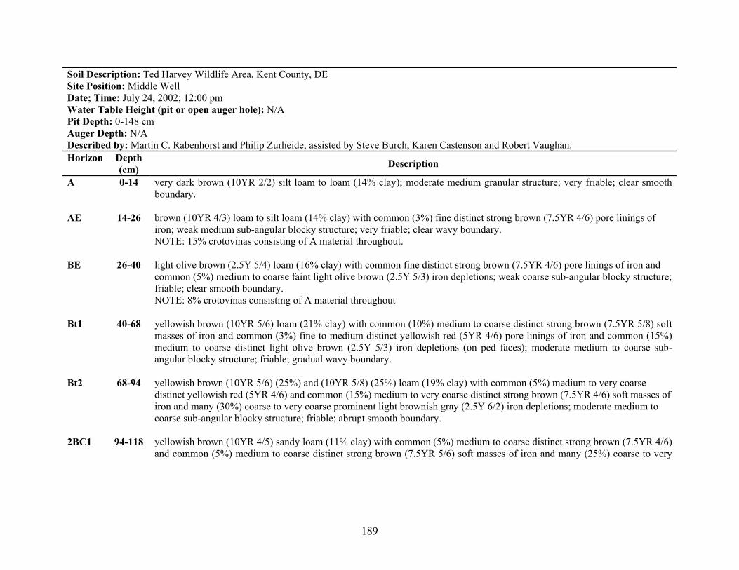
189
Soil Description: Ted Harvey Wildlife Area, Kent County, DE Site Position: Middle Well Date; Time: July 24, 2002; 12:00 pm Water Table Height (pit or open auger hole): N/A Pit Depth: 0-148 cm Auger Depth: N/A Described by: Martin C. Rabenhorst and Philip Zurheide, assisted by Steve Burch, Karen Castenson and Robert Vaughan. Horizon Depth
(cm) Description
A 0-14 very dark brown (10YR 2/2) silt loam to loam (14% clay); moderate medium granular structure; very friable; clear smooth boundary.
AE 14-26 brown (10YR 4/3) loam to silt loam (14% clay) with common (3%) fine distinct strong brown (7.5YR 4/6) pore linings of
iron; weak medium sub-angular blocky structure; very friable; clear wavy boundary. NOTE: 15% crotovinas consisting of A material throughout.
BE 26-40 light olive brown (2.5Y 5/4) loam (16% clay) with common fine distinct strong brown (7.5YR 4/6) pore linings of iron and
common (5%) medium to coarse faint light olive brown (2.5Y 5/3) iron depletions; weak coarse sub-angular blocky structure; friable; clear smooth boundary. NOTE: 8% crotovinas consisting of A material throughout
Bt1 40-68 yellowish brown (10YR 5/6) loam (21% clay) with common (10%) medium to coarse distinct strong brown (7.5YR 5/8) soft
masses of iron and common (3%) fine to medium distinct yellowish red (5YR 4/6) pore linings of iron and common (15%) medium to coarse distinct light olive brown (2.5Y 5/3) iron depletions (on ped faces); moderate medium to coarse sub-angular blocky structure; friable; gradual wavy boundary.
Bt2 68-94 yellowish brown (10YR 5/6) (25%) and (10YR 5/8) (25%) loam (19% clay) with common (5%) medium to very coarse
distinct yellowish red (5YR 4/6) and common (15%) medium to very coarse distinct strong brown (7.5YR 4/6) soft masses of iron and many (30%) coarse to very coarse prominent light brownish gray (2.5Y 6/2) iron depletions; moderate medium to coarse sub-angular blocky structure; friable; abrupt smooth boundary.
2BC1 94-118 yellowish brown (10YR 4/5) sandy loam (11% clay) with common (5%) medium to coarse distinct strong brown (7.5YR 4/6)
and common (5%) medium to coarse distinct strong brown (7.5YR 5/6) soft masses of iron and many (25%) coarse to very
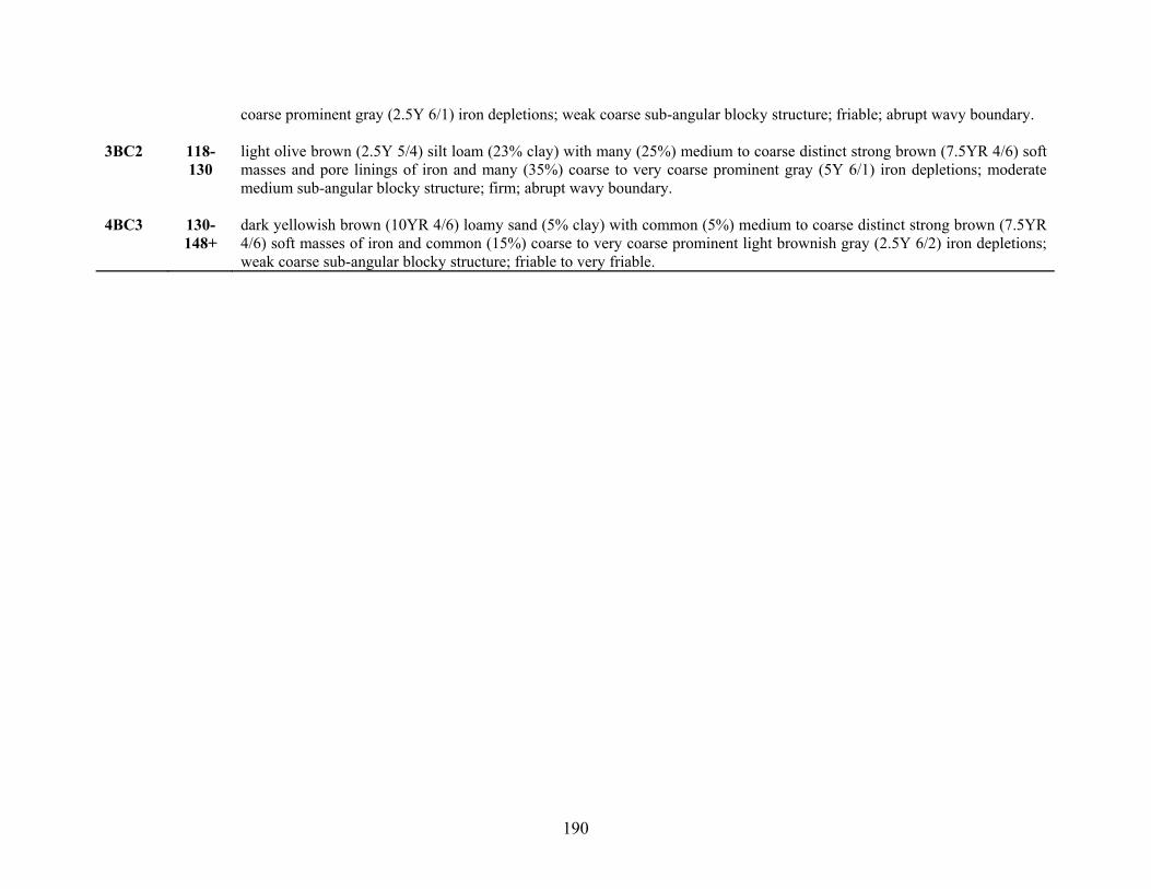
190
coarse prominent gray (2.5Y 6/1) iron depletions; weak coarse sub-angular blocky structure; friable; abrupt wavy boundary. 3BC2 118-
130 light olive brown (2.5Y 5/4) silt loam (23% clay) with many (25%) medium to coarse distinct strong brown (7.5YR 4/6) soft masses and pore linings of iron and many (35%) coarse to very coarse prominent gray (5Y 6/1) iron depletions; moderate medium sub-angular blocky structure; firm; abrupt wavy boundary.
4BC3 130-
148+ dark yellowish brown (10YR 4/6) loamy sand (5% clay) with common (5%) medium to coarse distinct strong brown (7.5YR 4/6) soft masses of iron and common (15%) coarse to very coarse prominent light brownish gray (2.5Y 6/2) iron depletions; weak coarse sub-angular blocky structure; friable to very friable.

191
Soil Description: Ted Harvey Wildlife Area, Kent County, DE Site Position: Upper Well Coordinates: N 39° 05’ 16.13” W 75° 24’ 23.13” Water Table Height (pit or open auger hole): N/A Pit Depth: 0-142 cm Auger Depth: N/A Described by: Martin C. Rabenhorst and Philip Zurheide, assisted by Steve Burch, Karen Castenson and Robert Vaughan. Horizon Depth
(cm) Description
A 0-9 very dark grayish brown (10YR 3/2) silt loam (11% clay); moderate medium granular structure; friable; clear smooth boundary.
AE 9-20 brown (10YR 4/3) silt loam (13% clay) with common (10%) fine to medium faint dark brown (7.5YR 3/4) soft masses of
iron; weak medium sub-angular blocky structure; friable; clear wavy boundary. EB 20-33 light olive brown (2.5Y 5/4) silt loam (16% clay) with few (1%) medium faint dark yellowish brown (10YR 4/4) pore linings
of iron and common (5%) medium faint light olive brown (2.5Y 5/3) iron depletions; weak medium to coarse platy parting to weak medium to coarse sub-angular blocky structure; friable; clear smooth boundary. NOTE: 5% inclusions of A-material as crotovinas.
Bt1 33-53 yellowish brown (10YR 5/6) silt loam (22% clay) with common (3%) fine distinct strong brown (7.5YR 4/6) soft masses of
iron and common (15%) medium to very coarse prominent dark yellowish brown (10YR 3/4) pore linings of iron and common (8%) medium prominent light brownish gray (2.5Y 6/2) iron depletions along root channels; moderate medium to coarse prismatic parting to moderate medium to coarse sub-angular blocky structure; friable; clear smooth boundary.
Bt2 52-68 yellowish brown (10YR 5/6) silt loam (21% clay) with common (10%) medium to coarse prominent dark yellowish brown
(10YR 3/4) pore linings of iron and common (10%) medium to coarse distinct strong brown (7.5YR 5/6) soft masses of iron and many (25%) medium prominent light brownish gray (2.5Y 6/2) iron depletions along root channels and ped faces; moderate medium to coarse sub-angular blocky structure; friable; clear wavy boundary.
2Bt3 68-83 yellowish brown (10YR 5/6) fine sandy loam (14% clay) with common (20%) medium to coarse distinct strong brown
(7.5YR 5/6) and common (20%) medium to coarse distinct yellowish brown (10YR 5/4) soft masses of iron and common (15%) medium to very coarse distinct light yellowish brown (2.5Y 6/3) and common (5%) medium to very coarse prominent

192
light yellowish gray (2.5Y 6/2) iron depletions; moderate medium sub-angular blocky structure; friable; abrupt smooth boundary.
2BC1 83-105 strong brown (7.5YR 5/6) (20%) and yellowish brown (10YR 5/6) (40%) sandy loam to loamy sand (8% clay) with faint
medium to coarse strong brown (7.5YR 4/6) soft masses of iron and common (5%) distinct pale brown (10YR 6/3) and common (5%) distinct light olive brown (2.5Y 5/3) iron depletions; weak very coarse platy parting to weak coarse sub-angular blocky structure; friable; clear wavy boundary.
2BC2 105-
125 light olive brown (2.5Y 5/6) sandy loam (15% clay) with common (10%) medium to coarse strong brown (7.5YR 4/6) soft masses of iron and common (5%) coarse to very coarse prominent gray (2.5Y 6/1) and common (10%) coarse to very coarse faint light olive brown (2.5Y 5/4) iron depletions; weak medium to coarse sub-angular blocky structure; friable; abrupt wavy boundary. NOTE: horizon extends down on right side.
3BC3 125-
142 light olive brown (2.5Y 5/4) silty clay loam (28% clay) with common (15%) medium to coarse distinct yellowish brown (10YR 5/6) iron concentrations and many (25%) coarse to very coarse distinct gray (2.5Y 5/1) iron depletions; moderate medium sub-angular blocky structure; firm. NOTE: representative material more on left side of horizon.

193
Appendix B: Organic Carbon Data
Blackwater (lower)
-1.00
-0.80
-0.60
-0.40
-0.20
0.000 10 20 30 40 50 60 70 80 90 100 110
Carbon (g/kg)
Dep
th (m
)
.
Blackwater (middle)
-1.00
-0.80
-0.60
-0.40
-0.20
0.000 10 20 30 40 50 60 70 80 90 100 110
Carbon (g/kg)
Dep
th (m
)
.
Blackwater (upper)
-1.00
-0.80
-0.60
-0.40
-0.20
0.000 10 20 30 40 50 60 70 80 90 100 110
Carbon (g/kg)
Dep
th (m
)
.

194
Isle of Wight (lower)
-1.00
-0.80
-0.60
-0.40
-0.20
0.000 10 20 30 40 50 60 70 80 90 100 110
Carbon (g/kg)
Dep
th (m
)
.
Isle of Wight (middle)
-1.00
-0.80
-0.60
-0.40
-0.20
0.000 10 20 30 40 50 60 70 80 90 100 110
Carbon (g/kg)
Dep
th (m
)
.
Isle of Wight (upper)
-1.00
-0.80
-0.60
-0.40
-0.20
0.000 10 20 30 40 50 60 70 80 90 100 110
Carbon (g/kg)
Dep
th (m
)
.

195
Eastern Neck (lower)
-1.00
-0.80
-0.60
-0.40
-0.20
0.000 10 20 30 40 50 60 70 80 90 100 110
Carbon (g/kg)
Dep
th (m
)
.
Eatern Neck (middle)
-1.00
-0.80
-0.60
-0.40
-0.20
0.000 10 20 30 40 50 60 70 80 90 100 110
Carbon (g/kg)
Dep
th (m
)
.
Eastern Neck (upper)
-1.00
-0.80
-0.60
-0.40
-0.20
0.000 10 20 30 40 50 60 70 80 90 100 110
Carbon (g/kg)
Dep
th (m
)
.
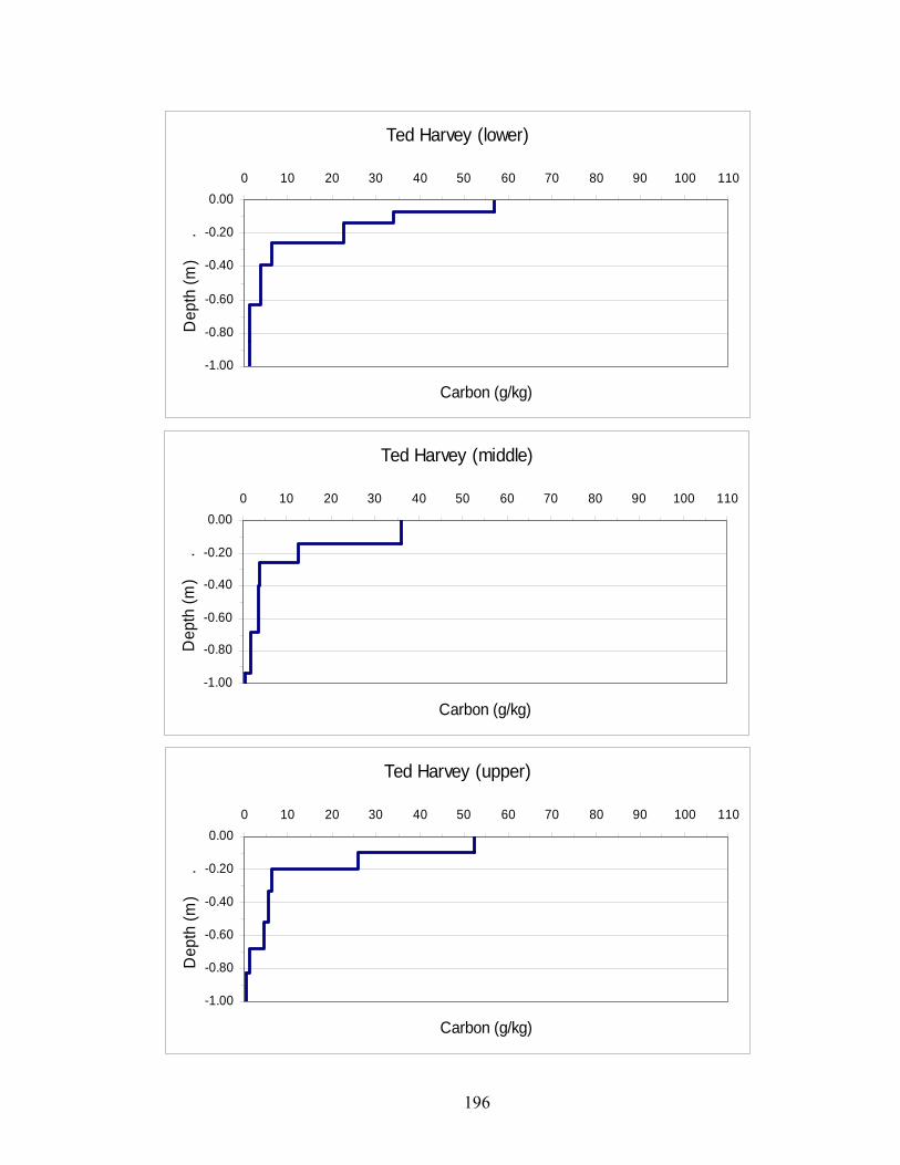
196
Ted Harvey (lower)
-1.00
-0.80
-0.60
-0.40
-0.20
0.000 10 20 30 40 50 60 70 80 90 100 110
Carbon (g/kg)
Dep
th (m
)
.
Ted Harvey (middle)
-1.00
-0.80
-0.60
-0.40
-0.20
0.000 10 20 30 40 50 60 70 80 90 100 110
Carbon (g/kg)
Dep
th (m
)
.
Ted Harvey (upper)
-1.00
-0.80
-0.60
-0.40
-0.20
0.000 10 20 30 40 50 60 70 80 90 100 110
Carbon (g/kg)
Dep
th (m
)
.

197
SITE Depth (cm) Average %C SITE Depth (cm) Average %CBWL 0-7 10.65 IOWL 0-9 2.55 BWL 7-16 0.98 IOWL 9-27 0.35 BWL 16-24 0.50 IOWL 27-45 0.26 BWL 24-39 0.41 IOWL 45-61 0.27 BWL 39-53 0.45 IOWL 61-90+ 0.07 BWL 53-66 0.14 BWL 66-77 0.10 IOWM 0-9 3.67 BWL 77-91 0.09 IOWM 9-20 0.93
IOWM 20-33 0.38 BWM 0-10 2.83 IOWM 33-49 0.37 BWM 10-22 0.37 IOWM 49-70 0.22 BWM 22-51 0.32 IOWM 70-89 0.07 BWM 51-103 0.15 IOWM 89-125 0.02 BWM 103-129 0.05
IOWU 0-10 5.72 BWU 0-10 2.82 IOWU 10-18 0.57 BWU 10-16 1.41 IOWU 18-31 0.22 BWU 16-33 0.45 IOWU 31-55 0.12 BWU 33-63 0.33 IOWU 55-77 0.10 BWU 63-83 0.07 IOWU 77-90 0.05 BWU 83-173 0.07 IOWU 90-137 0.02 BWU 173-207 0.06 IOWU 137-150 0.06 IOWU 150-183 0.05 IOWU 183-225 0.06 IOWU 225-259 0.04 IOWU 259-270 0.02

198
SITE Depth (cm) Average %C SITE Depth (cm) Average %C ENL 0-6 8.24 THL 0-7 5.67 ENL 6-15 2.45 THL 7-14 3.38 ENL 15-32 0.26 THL 14-26 2.26 ENL 32-42 0.25 THL 26-39 0.64 ENL 42-62 0.17 THL 39-63 0.38 ENL 62-77 0.06 THL 63-85 0.13 ENL 77-112 0.04 THL 85-124 0.11 ENL 112-143 0.05 THL 124-170 0.07 ENL 143-167 0.07 THL 170-235 0.14 ENL 167-179 0.06 THL 235-280 0.23 ENL 179-199 0.07 THL 280-310 0.21 ENL 199-215 0.05 THL 310-335 0.23 ENL 215-257 0.02 ENL 257-307 0.03 THM 0-14 3.60
THM 14-26 1.25 ENM 0-9 8.85 THM 26-40 0.37 ENM 9-15 3.94 THM 40-68 0.34 ENM 15-28 0.32 THM 68-94 0.19 ENM 28-45 0.20 THM 94-118 0.05 ENM 45-69 0.16 THM 118-130 0.09 ENM 69-92 0.10 THM 130-148+ 0.03 ENM 92-137 0.06 ENM 137-157 0.06 THU 0-9 5.23 ENM 157-192 0.06 THU 9-20 2.59 ENM 192-237 0.03 THU 20-33 0.64
THU 33-52 0.54 ENU 0-6 5.52 THU 52-68 0.45 ENU 6-14 2.58 THU 68-83 0.12 ENU 14-38 0.29 THU 83-105 0.05 ENU 38-56 0.16 THU 105-125 0.05 ENU 56-69 0.09 THU 125-142 0.12 ENU 69-90 0.07 ENU 90-104 0.09 ENU 104-121 0.07 ENU 121-155 0.06

199
Appendix C: Particle Size Analysis
Blackwater National Wildlife Refuge – Dorchester County, MD < 2 mm > 2 mm (sands)
------- % ------- -------------- % ------------- Pedon Hor. Depth (cm) S Si C FC VC C M F VF CF
Lower A 0-7 6.5 62.0 31.5 N/A 0.1 0.7 2.1 1.6 2.0 0.0 Eg 7-16 7.8 74.7 17.5 N/A 0.5 1.1 2.0 1.5 2.6 0.0 BEg 16-24 6.3 71.3 22.4 N/A 0.5 1.1 2.0 1.5 2.6 0.0 Btg1 24-39 5.2 62.8 32.0 N/A 0.3 0.7 1.6 1.2 2.4 0.0 Btg2 39-52 4.8 55.1 40.1 N/A 0.1 0.5 1.3 0.9 2.4 0.0 Bt1 53-66 8.3 62.3 29.3 N/A 0.3 0.3 0.8 0.8 2.5 0.0 Bt2 66-77 29.8 48.7 21.5 N/A 0.1 0.6 1.9 2.0 3.7 0.0 2BC 77-91 55.3 30.0 14.8 N/A 0.2 2.6 11.5 9.6 5.8 0.0
Middle A 0-10 9.8 79.3 10.9 N/A 0.2 1.2 2.8 2.3 3.2 0.0 BE/Bt 10-22 7.3 71.9 20.8 N/A 0.3 0.7 1.8 1.6 2.8 0.0 Btg 22-51 5.9 59.4 34.6 N/A 0.0 0.2 1.4 1.4 3.0 0.0 2Bt 51-103 42.1 41.7 16.2 N/A 0.5 2.6 14.4 15.3 9.3 0.0 2BC 103-129 86.7 7.2 6.1 N/A 1.8 3.3 22.2 39.9 19.4 0.5
Upper A 0-10 26.2 63.3 10.5 N/A 1.0 3.1 10.8 7.3 4.2 0.0 EA 10-16 24.5 64.1 11.4 N/A Bt1 16-33 23.7 59.9 16.3 N/A 0.5 2.5 9.8 7.0 3.9 0.0 Bt2 33-63 31.6 48.0 20.3 N/A 0.4 3.0 14.2 9.9 4.1 0.0 2BC1 63-83 64.2 22.3 13.5 N/A 0.6 7.3 31.6 18.9 5.8 0.1 2BC2 83-173 85.4 5.7 8.9 N/A 1.8 6.8 33.1 35.5 8.1 1.1 2BC3 173-207 87.7 5.8 6.5 N/A 15.0 20.4 37.5 13.5 1.3 5.2

200
Isle of Wight Wildlife Management Area – Worcester County, MD < 2 mm > 2 mm (sands)
------- % ------- -------------- % ------------- Pedon Hor. Depth (cm) S Si C FC VC C M F VF CF
Lower A 0-9 60.6 29.5 9.8 N/A 0.7 3.6 10.8 29.5 12.3 0.0 B/A 9-27 57.0 32.7 10.3 N/A 0.7 3.6 10.8 29.5 12.3 0.0 Bt1 27-45 55.0 30.5 14.5 N/A 0.4 2.6 10.1 29.6 12.2 0.0 Bt2 45-61 77.7 9.5 12.8 N/A 0.5 3.8 14.4 46.2 12.7 0.0 BC 61-90+ 93.1 1.4 5.5 N/A 0.9 3.2 16.9 57.9 14.2 0.1
Middle A 0-9 70.4 21.5 8.1 N/A 0.8 5.2 15.6 37.7 11.1 0.0 AE 9-20 68.8 24.6 6.6 N/A 0.8 4.6 14.6 37.3 11.6 0.0 EB 20-33 67.4 24.9 7.7 N/A 0.8 4.3 14.1 36.6 11.6 0.0 Bt1 33-49 63.4 23.9 12.7 N/A 0.9 4.6 13.5 32.5 11.8 0.0 Bt2 49-70 72.2 14.4 13.4 N/A 0.7 4.5 14.6 40.7 11.8 0.0 C1 70-89 89.9 4.0 6.0 N/A 1.6 6.1 19.2 52.5 10.5 0.1 C2 89-125+ 95.2 1.7 3.1 N/A 0.3 4.2 16.8 59.4 14.5 0.0
Upper A 0-10 70.5 20.6 8.9 N/A 0.4 6.6 13.8 38.5 11.1 0.0 AB 10-18 68.0 24.4 7.6 N/A 0.5 6.4 13.1 37.1 10.9 0.0 BA 18-31 64.1 26.9 8.9 N/A 0.8 5.7 12.4 35.0 10.2 0.0 Bt1 31-55 67.3 24.9 7.8 N/A 1.3 5.2 14.3 32.4 14.2 0.1 Bt2 55-77 84.0 7.7 8.3 N/A 2.2 8.2 18.9 41.7 13.0 0.2 BC 77-90 93.4 2.6 4.0 N/A 1.1 4.7 18.9 54.5 14.2 0.2 C1 90-137 97.7 1.8 0.5 N/A 0.2 3.4 18.3 58.1 17.7 0.0 C2 137-150 88.0 5.4 6.5 N/A 0.3 3.2 14.5 49.2 20.9 0.0 2Cg 150-183 70.1 19.2 10.7 N/A 0.8 3.7 12.4 32.4 20.7 0.1 3C'1 183-225 36.0 39.7 24.3 N/A 0.3 1.3 4.2 8.5 21.7 0.0 4C'2 225-259 66.7 26.5 6.8 N/A 0.2 1.0 5.2 21.7 38.6 0.0 5C3 259-270+ 86.6 12.8 0.6 N/A 0.1 0.2 3.2 29.4 53.7 0.0

201
Eastern Neck Island National Wildlife Refuge – Kent County, MD < 2 mm > 2 mm (sands)
------- % ------- -------------- % ------------- Pedon Horizon Depth (cm) S Si C FC VC C M F VF CF
Lower A 0-6 29.1 49.2 21.7 9.5 1.5 0.8 2.3 9.7 14.8 1.1 EA 6-15 34.3 51.0 14.7 3.8 0.2 0.8 2.7 12.0 18.5 -0.4 BE 15-32 36.3 49.9 13.8 N/A 0.5 0.8 2.7 11.6 20.7 0.3 Bt1 32-42 38.8 44.3 16.9 5.2 0.4 0.8 2.7 11.6 23.3 0.4 Bt2 42-62 44.7 37.7 17.6 6.5 0.6 1.1 2.8 12.3 27.9 2.1 2Bt3 62-77 60.3 21.2 18.5 5.3 0.1 0.3 1.4 12.2 46.3 0.1 2BC1 77-112 67.5 12.1 20.4 6.4 0.2 1.1 5 32.1 29.2 0 2BC2 112-143 75.0 10.7 14.3 4.4 0.3 1.7 6.7 46.5 19.8 0.2 2BC3 143-167 69.9 11.6 18.4 7.2 0.2 1.1 4.4 36.2 28 0.7 2BC4 167-179 78.6 11.8 9.7 2.9 0.1 1.2 4 31.2 42.1 0 2C1 179-199 82.1 8.3 9.5 3.2 0.1 0.4 1.5 33 47.1 0 2C2 199-215 83.3 8.4 8.3 3.2 0.1 0.7 2.4 40.5 39.5 0 2C3 215-257 82.7 8.4 8.9 4.1 0.2 0.7 2.3 33.5 46 0 2C4 257-307 78.0 13.9 8.1 2.7 0 0.3 0.9 11.1 65.7 0
Middle A 0-9 31.5 47.9 20.6 8.9 1.1 0.9 2.7 13.0 13.7 0.9 AE 9-15 35.1 47.6 17.3 6.6 0.5 1.1 3.2 13.1 17.2 -0.8 BE 15-28 38.0 48.6 13.4 N/A 0.3 0.9 3.0 14.0 19.7 0.1 Bt1 28-45 37.2 46.4 16.4 5.5 0.2 0.8 2.7 13.3 20.2 0.2 Bt2 45-69 45.3 38.5 16.2 7.2 0.3 0.8 3.2 16.4 24.6 0.1 2Bt3 69-92 59.3 23.2 17.5 6.6 0.1 0.3 2.2 16.1 40.5 -0.1 2BC1 92-137 72.1 9.7 18.3 8.6 0.1 1.7 7.3 44.7 18.3 0.5 2BC2 137-157 69.9 13.9 16.1 7.6 0.1 0.9 3.6 28.2 37.1 0.2 2C1 157-192 68.4 12.1 19.5 8.9 0.2 1.1 4.4 32.6 30.1 0.1 2C2 192-237 91.9 5.4 2.7 0.7 0.1 0.3 1.8 40.5 49.2 0
Upper A 0-6 37.4 47.4 15.2 6.3 0.5 1.2 3.5 14.0 18.2 0.0 AE 6-14 34.8 51.2 14.0 4.2 0.4 1.0 3.3 13.0 17.1 0.0 EB 14-38 34.8 53.7 11.5 3.1 0.1 0.8 3.0 13.3 17.5 0.0 Bt1 38-56 33.4 49.9 16.8 5.5 0.2 0.9 3.1 12.3 16.8 0.0 Bt2 56-69 53.8 30.6 15.6 6.4 0.2 1.6 5.1 20.5 26.4 0.0 BCt 69-90 76.6 11.1 12.4 6.6 0.1 1.7 7.7 37.7 29.4 0.0 2Bt 90-104 52.0 23.6 24.4 9.8 0.1 0.3 1.1 7.6 42.9 0.0 2BC1 104-121 65.9 14.7 19.4 8.1 0.1 0.7 3.7 26.8 34.5 0.0 2BC2 121-155 71.6 10.0 18.4 8.3 0.2 1.6 6.6 46.8 16.4 0.1

202
Ted Harvey Wildlife Area – Kent County, DE < 2 mm > 2 mm (sands)
------- % ------- -------------- % ------------- Pedon Hor Depth (cm) S Si C FC VC C M F VF CF
Lower A1 0-7 31.3 49.5 19.2 N/A 0.9 5.5 10.7 9.6 4.5 0.0 A2 7-14 34.6 * * N/A 0.6 6.5 12.1 10.4 5.1 0.1 AE 14-26 33.5 53.3 13.2 N/A 0.6 6.0 11.3 10.4 5.1 0.0 EB 26-39 33.3 55.1 11.5 3.3 0.5 3.6 12.1 10.3 6.8 0.0 Bt 39-63 41.8 * * N/A 0.9 4.6 15.2 13.3 7.7 0.5 2BC1 63-85 78.4 14.9 6.6 3.1 1.2 12.1 35.5 25.5 4.1 0.0 3BC2 85-124 25.2 63.0 11.8 3.6 0.6 2.7 5.6 5.7 10.6 0.0 3BCg 124-170 8.8 69.2 22.0 9.6 0.2 0.8 1.7 2.0 4.1 0.0 ** 170-235 43.3 28.5 28.2 8.2 3.0 6.4 17.0 13.4 3.5 5.6 ** 235-280 28.4 34.4 37.2 9.4 1.5 3.9 12.2 8.8 1.9 1.2 ** 280-310 6.9 36.2 56.9 19.4 0.3 0.8 2.1 2.1 1.5 0.1 ** 310-335+ 11.8 33.4 54.9 19.3 1.4 3.0 3.5 2.7 1.2 0.1
Middle A 0-14 40.9 43.9 15.2 6.2 1.7 6.9 14.8 12.4 5.1 0.1 AE 14-26 44.9 44.7 10.5 3.9 1.4 6.7 16.6 14.3 5.8 0.1 BE 26-40 45.1 45.4 9.5 N/A 1.6 6.1 16.2 14.7 6.5 0.7 Bt1 40-68 44.4 41.8 13.9 6.1 2.2 6.8 15.8 13.4 6.1 0.7 Bt2 68-94 40.8 33.5 25.7 5.2 1.3 4.9 13.2 12.8 8.6 0.2 2BC1 94-118 62.5 29.2 8.3 N/A 3.1 11.4 22.8 19.0 6.2 N/A 3BC3 118-130 21.2 60.8 18.0 N/A 1.1 3.3 6.8 5.8 4.3 N/A 4BC3 130-148+ 74.0 16.2 9.8 N/A 4.5 13.0 26.6 23.5 6.4 N/A
Upper A 0-9 17.9 62.1 19.9 8.3 0.8 2.9 5.7 5.0 3.6 0.1 AE 9-20 18.6 65.4 16.0 6.0 0.5 2.7 5.7 5.3 4.3 0.1 EB 20-33 18.8 67.5 13.8 N/A 0.3 1.9 5.2 5.1 6.3 0.0 Bt1 33-52 14.6 67.1 18.3 N/A 0.3 1.5 3.7 3.9 5.2 N/A Bt2 52-68 17.7 62.2 20.0 N/A 0.3 1.4 4.1 4.5 7.4 N/A 2Bt3 68-83 36.0 50.0 14.0 N/A 0.7 3.1 10.2 11.6 10.4 N/A 2BC1 83-105 74.2 18.0 7.8 N/A 4.9 14.4 25.8 20.4 8.7 N/A 2BC2 105-125 74.5 16.4 9.0 N/A 3.9 13.8 27.9 22.7 6.2 N/A 3BC3 125-142+ 12.8 47.0 40.2 N/A 0.3 1.7 4.1 4.0 2.7 N/A
* sample lost ** auger sample
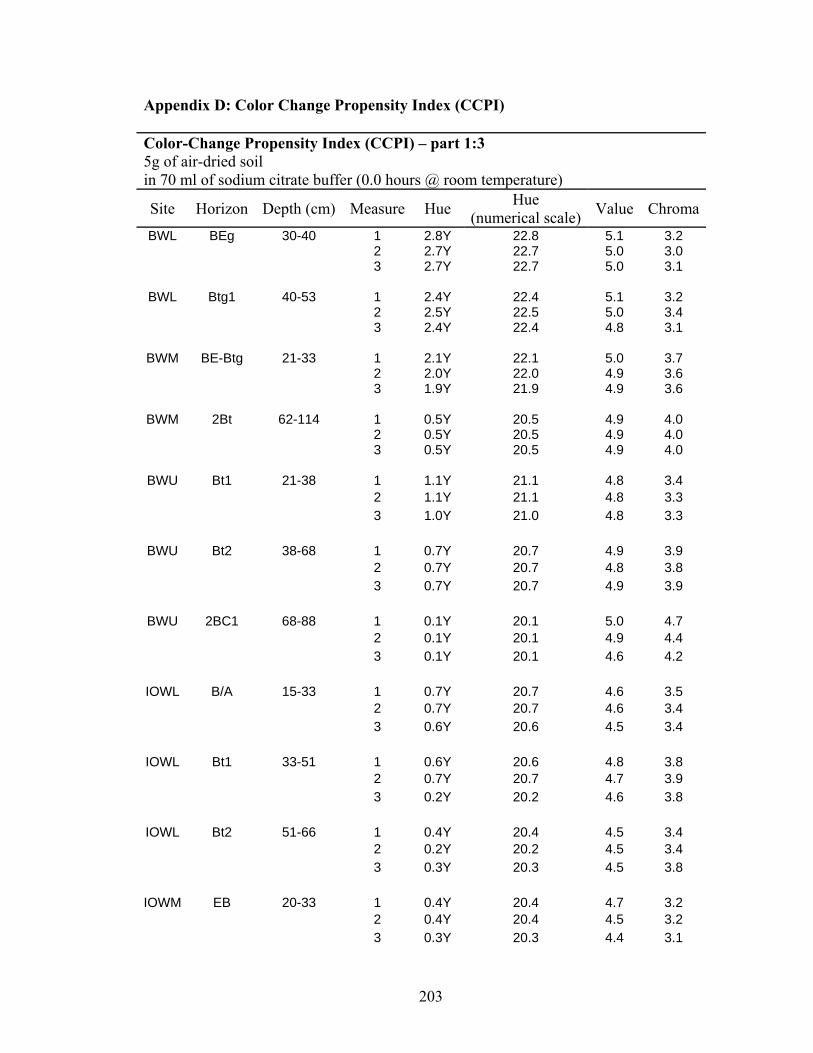
203
Appendix D: Color Change Propensity Index (CCPI) Color-Change Propensity Index (CCPI) – part 1:3 5g of air-dried soil in 70 ml of sodium citrate buffer (0.0 hours @ room temperature)
Site Horizon Depth (cm) Measure Hue Hue (numerical scale) Value Chroma
BWL BEg 30-40 1 2.8Y 22.8 5.1 3.2 2 2.7Y 22.7 5.0 3.0 3 2.7Y 22.7 5.0 3.1
BWL Btg1 40-53 1 2.4Y 22.4 5.1 3.2 2 2.5Y 22.5 5.0 3.4 3 2.4Y 22.4 4.8 3.1
BWM BE-Btg 21-33 1 2.1Y 22.1 5.0 3.7 2 2.0Y 22.0 4.9 3.6 3 1.9Y 21.9 4.9 3.6
BWM 2Bt 62-114 1 0.5Y 20.5 4.9 4.0 2 0.5Y 20.5 4.9 4.0 3 0.5Y 20.5 4.9 4.0
BWU Bt1 21-38 1 1.1Y 21.1 4.8 3.4 2 1.1Y 21.1 4.8 3.3 3 1.0Y 21.0 4.8 3.3
BWU Bt2 38-68 1 0.7Y 20.7 4.9 3.9 2 0.7Y 20.7 4.8 3.8 3 0.7Y 20.7 4.9 3.9
BWU 2BC1 68-88 1 0.1Y 20.1 5.0 4.7 2 0.1Y 20.1 4.9 4.4 3 0.1Y 20.1 4.6 4.2
IOWL B/A 15-33 1 0.7Y 20.7 4.6 3.5 2 0.7Y 20.7 4.6 3.4 3 0.6Y 20.6 4.5 3.4
IOWL Bt1 33-51 1 0.6Y 20.6 4.8 3.8 2 0.7Y 20.7 4.7 3.9 3 0.2Y 20.2 4.6 3.8
IOWL Bt2 51-66 1 0.4Y 20.4 4.5 3.4 2 0.2Y 20.2 4.5 3.4 3 0.3Y 20.3 4.5 3.8
IOWM EB 20-33 1 0.4Y 20.4 4.7 3.2 2 0.4Y 20.4 4.5 3.2 3 0.3Y 20.3 4.4 3.1

204
IOWM Bt1 33-49 1 0.1Y 20.1 4.5 3.7
2 0.1Y 20.1 4.5 3.7 3 0.1Y 20.1 4.5 3.7
IOWM Bt2 49-70 1 0.1Y 20.1 4.6 4.1 2 0.1Y 20.1 4.7 4.1 3 0.1Y 20.1 4.3 3.9
IOWU AB 10-18 1 0.6Y 20.6 3.7 2.2 2 0.7Y 20.7 3.7 2.2 3 0.7Y 20.7 3.8 2.3
IOWU BA 18-31 1 0.5Y 20.5 4.4 3.3 2 0.5Y 20.5 4.5 3.4 3 0.4Y 20.4 4.5 3.4
IOWU Bt1 31-55 1 0.9Y 20.9 4.8 3.8 2 0.7Y 20.7 4.7 3.6 3 0.5Y 20.5 4.7 3.8
THL AE 14-26 1 9.5YR 19.5 3.3 1.5 2 9.7YR 19.7 3.3 1.5 3 9.6YR 19.6 3.3 1.5
THL EB 26-39 1 0.1Y 20.1 3.7 4.6 2 0.1Y 20.1 4.5 2.9 3 0.1Y 20.1 4.4 2.9
THL Bt1 39-63 1 0.1Y 20.1 4.6 3.7 2 0.1Y 20.1 4.5 3.6 3 0.1Y 20.1 4.3 3.6
THM AE 14-26 1 0.1Y 20.1 3.7 2.2 2 0.1Y 20.1 3.7 2.2 3 0.1Y 20.1 3.7 2.2
THM BE 26-40 1 0.3Y 20.3 4.6 3.1 2 0.3Y 20.3 4.4 3.1 3 0.2Y 20.2 4.5 3.1
THM Bt1 40-68 1 0.1Y 20.1 4.7 3.8 2 0.1Y 20.1 4.8 3.9 3 0.1Y 20.1 4.8 3.9
THU EB 20-33 1 0.1Y 20.1 4.6 3.1 2 0.1Y 20.1 4.7 3.1 3 0.1Y 20.1 4.5 3.1

205
THU Bt1 33-52 1 0.1Y 20.1 4.7 3.7 2 0.1Y 20.1 4.7 3.8 3 0.1Y 20.1 4.6 3.5
THU Bt2 52-68 1 0.1Y 20.1 4.8 3.8 2 0.1Y 20.1 4.6 3.8 3 0.1Y 20.1 4.6 3.7
ENL BE 18-35 1 0.9Y 20.9 5.1 3.8 2 0.9Y 20.9 5.0 3.8 3 0.8Y 20.8 4.8 3.7
ENL Bt1 35-45 1 0.4Y 20.4 4.9 4.1 2 0.4Y 20.4 4.7 4.0 3 0.1Y 20.1 4.9 4.1
ENL Bt2 45-65 1 0.1Y 20.1 4.9 4.2 2 0.1Y 20.1 4.8 4.1 3 0.1Y 20.1 4.9 4.2
ENM BE 18-31 1 1.4Y 21.4 5.1 3.5 2 1.5Y 21.5 5.1 3.5 3 1.5Y 21.5 5.1 3.4
ENM Bt1 31-48 1 1.0Y 21.0 5.2 4.2 2 1.0Y 21.0 5.1 4.2 3 0.9Y 20.9 4.9 4.1
ENM 2Bt3 72-95 1 1.2Y 21.2 5.3 4.2 2 1.4Y 21.4 5.0 4.1 3 1.2Y 21.2 5.1 4.1
ENU AE 6-14 1 0.1Y 20.1 3.6 2.0 2 0.1Y 20.1 3.6 2.1 3 0.1Y 20.1 3.3 2.0
ENU EB 14-38 1 1.0Y 21.0 5.1 3.6 2 1.0Y 21.0 4.9 3.6 3 0.9Y 20.9 4.9 3.6
ENU Bt1 38-56 1 0.8Y 20.8 5.1 4.1 2 0.6Y 20.6 5.1 4.1 3 0.6Y 20.6 5.1 4.1
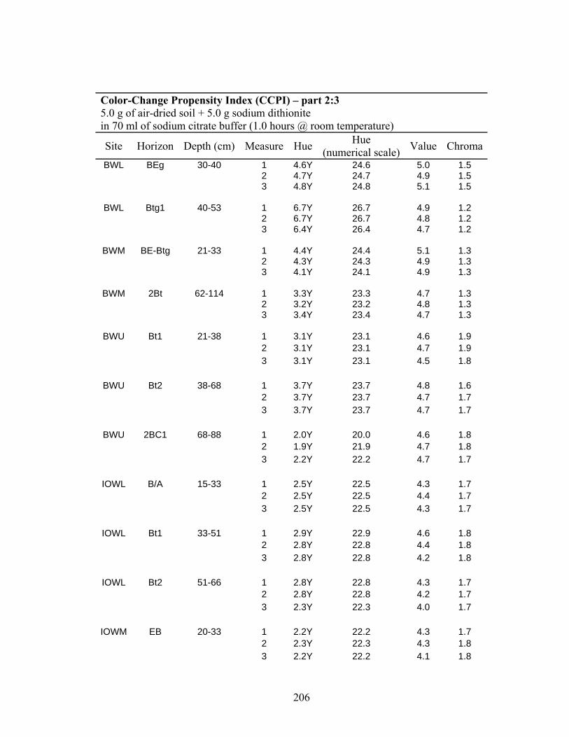
206
Color-Change Propensity Index (CCPI) – part 2:3 5.0 g of air-dried soil + 5.0 g sodium dithionite in 70 ml of sodium citrate buffer (1.0 hours @ room temperature)
Site Horizon Depth (cm) Measure Hue Hue (numerical scale) Value Chroma
BWL BEg 30-40 1 4.6Y 24.6 5.0 1.5 2 4.7Y 24.7 4.9 1.5 3 4.8Y 24.8 5.1 1.5
BWL Btg1 40-53 1 6.7Y 26.7 4.9 1.2 2 6.7Y 26.7 4.8 1.2 3 6.4Y 26.4 4.7 1.2
BWM BE-Btg 21-33 1 4.4Y 24.4 5.1 1.3 2 4.3Y 24.3 4.9 1.3 3 4.1Y 24.1 4.9 1.3
BWM 2Bt 62-114 1 3.3Y 23.3 4.7 1.3 2 3.2Y 23.2 4.8 1.3 3 3.4Y 23.4 4.7 1.3
BWU Bt1 21-38 1 3.1Y 23.1 4.6 1.9 2 3.1Y 23.1 4.7 1.9 3 3.1Y 23.1 4.5 1.8
BWU Bt2 38-68 1 3.7Y 23.7 4.8 1.6 2 3.7Y 23.7 4.7 1.7 3 3.7Y 23.7 4.7 1.7
BWU 2BC1 68-88 1 2.0Y 20.0 4.6 1.8 2 1.9Y 21.9 4.7 1.8 3 2.2Y 22.2 4.7 1.7
IOWL B/A 15-33 1 2.5Y 22.5 4.3 1.7 2 2.5Y 22.5 4.4 1.7 3 2.5Y 22.5 4.3 1.7
IOWL Bt1 33-51 1 2.9Y 22.9 4.6 1.8 2 2.8Y 22.8 4.4 1.8 3 2.8Y 22.8 4.2 1.8
IOWL Bt2 51-66 1 2.8Y 22.8 4.3 1.7 2 2.8Y 22.8 4.2 1.7 3 2.3Y 22.3 4.0 1.7
IOWM EB 20-33 1 2.2Y 22.2 4.3 1.7 2 2.3Y 22.3 4.3 1.8 3 2.2Y 22.2 4.1 1.8

207
IOWM Bt1 33-49 1 2.5Y 22.5 4.5 1.6
2 2.4Y 22.4 4.6 1.6 3 2.4Y 22.4 4.4 1.5
IOWM Bt2 49-70 1 2.7Y 22.7 4.6 1.7 2 2.8Y 22.8 4.4 1.7 3 2.7Y 22.7 4.6 1.7
IOWU AB 10-18 1 2.2Y 22.2 3.7 1.4 2 2.2Y 22.2 3.8 1.4 3 2.1Y 22.1 3.8 1.4
IOWU BA 18-31 1 2.9Y 22.9 4.2 1.9 2 2.8Y 22.8 4.4 1.9 3 2.8Y 22.8 4.1 1.8
IOWU Bt1 31-55 1 3.0Y 23.0 4.5 1.8 2 3.0Y 23.0 4.4 1.9 3 3.0Y 23.0 4.5 2.0
THL AE 14-26 1 0.9Y 20.9 3.4 1.1 2 0.8Y 20.8 3.4 1.1 3 1.2Y 21.2 3.3 1.1
THL EB 26-39 1 2.4Y 22.4 4.5 1.5 2 2.6Y 22.6 4.4 1.6 3 2.6Y 22.6 4.1 1.5
THL Bt1 39-63 1 3.1Y 23.1 4.7 1.5 2 3.1Y 23.1 4.6 1.5 3 2.8Y 22.8 4.5 1.4
THM AE 14-26 1 1.7Y 21.7 3.7 1.4 2 1.8Y 21.8 3.8 1.4 3 1.7Y 21.7 3.7 1.4
THM BE 26-40 1 2.9Y 22.9 4.3 1.5 2 2.7Y 22.7 4.4 1.5 3 2.7Y 22.7 4.4 1.6
THM Bt1 40-68 1 3.3Y 23.3 4.8 1.5 2 3.5Y 23.5 4.8 1.5 3 3.5Y 23.5 4.7 1.5
THU EB 20-33 1 2.4Y 22.4 4.5 1.7 2 2.4Y 22.4 4.3 1.7 3 2.4Y 22.4 4.5 1.7
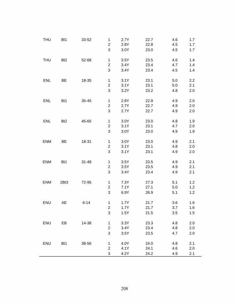
208
THU Bt1 33-52 1 2.7Y 22.7 4.6 1.7 2 2.8Y 22.8 4.5 1.7 3 3.0Y 23.0 4.5 1.7
THU Bt2 52-68 1 3.5Y 23.5 4.6 1.4 2 3.4Y 23.4 4.7 1.4 3 3.4Y 23.4 4.5 1.4
ENL BE 18-35 1 3.1Y 23.1 5.0 2.2 2 3.1Y 23.1 5.0 2.1 3 3.2Y 23.2 4.8 2.0
ENL Bt1 35-45 1 2.8Y 22.8 4.9 2.0 2 2.7Y 22.7 4.9 2.0 3 2.7Y 22.7 4.9 2.0
ENL Bt2 45-65 1 3.0Y 23.0 4.8 1.9 2 3.1Y 23.1 4.7 2.0 3 3.0Y 23.0 4.9 1.9
ENM BE 18-31 1 3.0Y 23.0 4.9 2.1 2 3.1Y 23.1 4.8 2.0 3 3.1Y 23.1 4.9 2.0
ENM Bt1 31-48 1 3.5Y 23.5 4.9 2.1 2 3.5Y 23.5 4.9 2.1 3 3.4Y 23.4 4.9 2.1
ENM 2Bt3 72-95 1 7.3Y 27.3 5.1 1.2 2 7.1Y 27.1 5.0 1.2 3 6.9Y 26.9 5.1 1.2
ENU AE 6-14 1 1.7Y 21.7 3.6 1.6 2 1.7Y 21.7 3.7 1.6 3 1.5Y 21.5 3.5 1.5
ENU EB 14-38 1 3.3Y 23.3 4.8 2.0 2 3.4Y 23.4 4.8 2.0 3 3.5Y 23.5 4.7 2.0
ENU Bt1 38-56 1 4.0Y 24.0 4.8 2.1 2 4.1Y 24.1 4.6 2.0 3 4.2Y 24.2 4.9 2.1

209
Color-Change Propensity Index (CCPI) – part 3:3 5.0 g of air-dried soil + 5.0 g sodium dithionite in 70 ml of sodium citrate buffer (2 x 2.0 hours @ 80°C)
Site Horizon Depth (cm) Measure Hue Hue (numerical scale) Value Chroma
BWL BEg 30-40 1 4.8Y 24.8 5.1 0.6
2 4.7Y 24.7 5.1 0.6 3 4.8Y 24.8 5.1 0.6
BWL Btg1 40-53 1 1.1GY 31.1 5.0 0.4 2 1.5GY 31.5 5.0 0.4 3 1.2GY 31.2 5.1 0.4
BWM BE-Btg 21-33 1 5.0Y 25.0 4.9 0.6 2 4.7Y 24.7 4.9 0.6 3 5.1Y 25.1 4.8 0.6
BWM 2Bt 62-114 1 4.1GY 34.1 4.9 0.4 2 5.1GY 35.1 4.9 0.4 3 4.8GY 34.8 4.8 0.4
BWU Bt1 21-38 1 5.7Y 25.7 5.0 0.7 2 5.7Y 25.7 4.8 0.6 3 5.6Y 25.6 4.9 0.6
BWU Bt2 38-68 1 1.0GY 31.0 4.9 0.4 2 .6GY 30.6 5.0 0.5 3 1.0GY 31.0 4.8 0.4
BWU 2BC1 68-88 1 7.5Y 27.5 5.0 0.5 2 7.3Y 27.3 5.0 0.5 3 6.6Y 26.6 4.9 0.5
IOWL B/A 15-33 1 5.7Y 25.7 4.7 0.7 2 5.2Y 25.2 4.5 0.6 3 5.5Y 25.5 4.6 0.7
IOWL Bt1 33-51 1 8.5Y 28.5 4.7 0.5 2 8.8Y 28.8 5.0 0.5 3 8.7Y 28.7 4.8 0.5
IOWL Bt2 51-66 1 9.6Y 29.6 4.5 0.5 2 9.1Y 29.1 4.7 0.5 3 8.3Y 28.3 4.6 0.5
IOWM EB 20-33 1 4.0Y 24.0 4.4 0.8 2 4.1Y 24.1 4.4 0.8

210
3 4.3Y 24.3 4.5 0.8
IOWM Bt1 33-49 1 6.8Y 26.8 4.7 0.6 2 6.7Y 26.7 4.7 0.5 3 7.0Y 27.0 4.7 0.5
IOWM Bt2 49-70 1 2 3
IOWU AB 10-18 1 1.9Y 21.9 3.7 0.8 2 1.9Y 21.9 3.8 0.8 3 1.7Y 21.7 3.8 0.8
IOWU BA 18-31 1 5.4Y 25.4 4.7 0.7 2 5.2Y 25.4 4.6 0.7 3 5.4Y 25.4 4.6 0.7
IOWU Bt1 31-55 1 7.8Y 27.8 4.7 0.5 2 7.8Y 27.8 4.8 0.6 3 8.0Y 28.0 4.6 0.5
THL AE 14-26 1 1.1Y 21.1 3.3 0.7 2 1.4Y 21.4 3.2 0.8 3 0.9Y 20.9 3.3 0.7
THL EB 26-39 1 4.4Y 24.4 4.2 0.8 2 4.3Y 24.3 4.3 0.7 3 4.2Y 24.2 4.2 0.7
THL Bt1 39-63 1 0.9GY 30.9 4.7 0.4 2 0.7GY 30.7 4.6 0.4 3 1.3GY 31.3 4.7 0.4
THM AE 14-26 1 2.1Y 22.1 3.8 0.8 2 2.1Y 22.1 3.7 0.8 3 2.1Y 22.1 3.7 0.8
THM BE 26-40 1 5.0Y 25.0 4.6 0.7 2 5.2Y 25.2 4.5 0.7 3 4.8Y 24.8 4.5 0.8
THM Bt1 40-68 1 0.9GY 30.9 4.7 0.4 2 1.1GY 31.1 4.8 0.4 3 0.8GY 30.8 4.7 0.5
THU EB 20-33 1 5.1Y 25.1 4.6 0.7 2 5.2Y 25.2 4.5 0.7

211
3 5.3Y 25.3 4.6 0.7
THU Bt1 33-52 1 9.0Y 29.0 4.8 0.5 2 9.1Y 29.1 4.6 0.5 3 9.3Y 29.3 4.6 0.5
THU Bt2 52-68 1 6.2GY 36.2 4.6 0.4 2 6.0GY 36.0 4.6 0.4 3 6.5GY 36.5 4.6 0.4
ENL BE 18-35 1 6.8Y 26.8 5.1 0.7 2 7.1Y 27.1 5.1 0.6 3 6.8Y 26.8 5.1 0.7
ENL Bt1 35-45 1 .2GY 30.2 5.2 0.5 2 .3GY 30.3 5.2 0.5 3 .1GY 30.1 5.4 0.5
ENL Bt2 45-65 1 1.9GY 31.9 5.1 0.5 2 1.7GY 31.7 5.0 0.5 3 2.6GY 32.6 4.9 0.5
ENM BE 18-31 1 5.7Y 25.7 5.0 0.7 2 5.6Y 25.6 5.1 0.7 3 5.7Y 25.7 5.0 0.7
ENM Bt1 31-48 1 1.0GY 31.0 5.4 0.5 2 .2GY 30.2 5.3 0.5 3 .7GY 30.7 5.3 0.5
ENM 2Bt3 72-95 1 6.8GY 36.8 5.3 0.5 2 6.9GY 36.9 5.1 0.5 3 6.8GY 36.8 5.2 0.5
ENU AE 6-14 1 2.2Y 22.2 3.8 0.9 2 1.8Y 21.8 3.8 0.9 3 2.0Y 22.0 3.7 0.8
ENU EB 14-38 1 6.7Y 26.7 5.0 0.7 2 6.7Y 26.7 5.1 0.7 3 6.9Y 26.9 5.0 0.7
ENU Bt1 38-56 1 3.6GY 33.6 5.2 0.4 2 3.8GY 33.8 5.3 0.4 3 3.5GY 33.5 5.1 0.4

212
Research Site
Blackwater Isle of Wight Eastern Neck Ted Harvey Pos. Hor. CCPI Pos. Hor. CCPI Pos. Hor. CCPI Pos. Hor. CCPI up 2BC1 55.1 low Bt2 53.6 low Bt1 55.4 up Bt2 53.1
mid 2Bt 55.8 low Bt1 58.2 low Bt2 57.0 low Bt1 57.0 up Bt2 60.8 up Bt1 59.6 mid Bt1 57.1 up Bt1 58.7 up Bt1 66.7 low B/A 63.1 up Bt1 57.5 mid Bt1 63.4 low Btg1 74.8 mid Bt1 64.4 mid BE 60.6 up EB 65.9 mid BE-Btg 108.1 mid EB 70.2 low BE 63.3 mid BE 74.8 low BEg 119.5 up BA 70.6 up EB 66.4 low EB 84.3
up AB 141.0 mid 2Bt3 75.5 mid AE 93.7 up AE 89.1 low AE 95.4
Color Change Propensity Index of ABLS-soils
0 25 50 75 100 125 150
CCPI
BlackwaterIsle of WightEastern NeckTed Harvey
30-40?
Non-ProblematicProblematic

213
Appendix E: Water Tables Graphs (relative to the soil surface)
Mar-2001Jun-2001
Sep-2001Dec-2001
Mar-2002Jun-2002
Sep-2002Dec-2002
Mar-2003Jun-2003
Sep-2003Dec-2003
Mar-2004-1.75
-1.5
-1.25
-1
-0.75
-0.5
-0.25
0
0.25
0.5
0.75
Dep
th (m
)
Upper Well Middle Well Lower Well
Water TablesBlackwater NWR - Dorchester County, MD
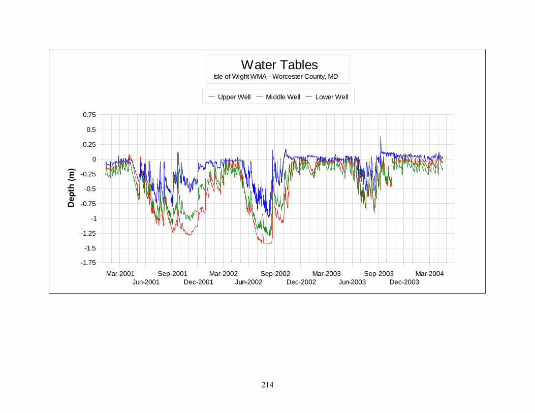
214
Mar-2001Jun-2001
Sep-2001Dec-2001
Mar-2002Jun-2002
Sep-2002Dec-2002
Mar-2003Jun-2003
Sep-2003Dec-2003
Mar-2004-1.75
-1.5
-1.25
-1
-0.75
-0.5
-0.25
0
0.25
0.5
0.75
Dep
th (m
)
Upper Well Middle Well Lower Well
Water TablesIsle of Wight WMA - Worcester County, MD

215
Mar-2001Jun-2001
Sep-2001Dec-2001
Mar-2002Jun-2002
Sep-2002Dec-2002
Mar-2003Jun-2003
Sep-2003Dec-2003
Mar-2004-1.75
-1.5
-1.25
-1
-0.75
-0.5
-0.25
0
0.25
0.5
0.75
Dep
th (m
)
Upper Well Middle Well Lower Well
Water TablesEastern Neck NWR - Kent County, MD
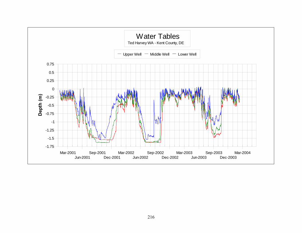
216
Mar-2001Jun-2001
Sep-2001Dec-2001
Mar-2002Jun-2002
Sep-2002Dec-2002
Mar-2003Jun-2003
Sep-2003Dec-2003
Mar-2004-1.75
-1.5
-1.25
-1
-0.75
-0.5
-0.25
0
0.25
0.5
0.75
Dep
th (m
)
Upper Well Middle Well Lower Well
Water TablesTed Harvey WA - Kent County, DE

217
Appendix F: Redox Potential Data Blackwater -------------- cm -------------- 15-Feb-01 10 20 30 40 50
circuit ---------- Eh (mV) ---------- Lower 1 329 290 124 201 227Well 2 168 146 134 16 226
3 313 180 154 223 253 4 265 163 146 206 221 5 335 227 199 234 228 6 282 56 31 162 224
mean (mV) 282 177 131 174 230
Middle 1 407 400 378 355 262Well 2 320 312 289 256 262
3 274 254 239 66 219 4 354 336 256 222 222 5 305 365 245 115 183 6 225 311 231 184 198
mean (mV) 314 330 273 200 224
Upper 1 232 218 362 343 281Well 2 285 213 309 269 253
3 296 344 253 278 225 4 343 212 375 304 233 5 411 284 276 236 213 6 261 196 295 248 255
mean (mV) 305 245 312 280 243
Blackwater Soil Redox Potentials(mean values of six electrodes at each depth)
February 15, 20010
10
20
30
40
50
60-100 0 100 200 300 400 500 600 700
Eh (mV)
Dep
th (c
m)
lowermiddleupper
Blackwater Soil Redox Potentials(mean values of six electrodes at each depth)
February 27, 20010
10
20
30
40
50
60-100 0 100 200 300 400 500 600 700
Eh (mV)
Dep
th (c
m)
lowermiddleupper
Blackwater -------------- cm -------------- 27-Feb-01 10 20 30 40 50
circuit ---------- Eh (mV) ---------- Lower 1 346 112 84 91 179Well 2 128 158 20 172 198
3 244 205 161 175 134 4 308 319 142 180 191 5 291 294 91 147 205 6 283 147 84 140 173
mean (mV) 267 206 97 151 180
Middle 1 101 301 339 97 194Well 2 -26 198 12 224 217
3 117 122 121 149 125 4 310 282 456 -11 177 5 304 259 246 179 221 6 99 248 308 316 256
mean (mV) 151 235 247 159 198
Upper 1 341 365 254 288 258Well 2 345 256 163 251 235
3 226 121 110 124 72 4 270 188 172 279 287 5 360 246 181 228 251 6 331 270 268 254 263
mean (mV) 312 241 191 237 228

218
Blackwater -------------- cm -------------- 19-Mar-01 10 20 30 40 50
circuit ---------- Eh (mV) ---------- Lower 1 239 174 161 135 241Well 2 179 285 89 174 209
3 217 174 -43 -6 78 4 254 73 -30 111 183 5 254 161 16 124 146 6 254 89 137 61 222
mean (mV) 233 159 55 100 180
Middle 1 272 263 227 239 219Well 2 119 197 251 220 299
3 134 272 120 147 60 4 272 178 188 193 144 5 135 143 142 155 67 6 53 275 286 321 311
mean (mV) 164 221 202 213 183
Upper 1 187 183 155 239 219Well 2 169 260 219 220 299
3 165 200 148 147 60 4 294 227 287 193 144 5 192 132 182 155 67 6 313 234 261 321 311
mean (mV) 220 206 209 213 183
Blackwater Soil Redox Potentials(mean values of six electrodes at each depth)
March 19, 20010
10
20
30
40
50
60-100 0 100 200 300 400 500 600 700
Eh (mV)
Dep
th (c
m)
lowermiddleupper
Blackwater Soil Redox Potentials(mean values of six electrodes at each depth)
April 3, 20010
10
20
30
40
50
60-100 0 100 200 300 400 500 600 700
Eh (mV)
Dep
th (c
m)
lowermiddleupper
Blackwater -------------- cm -------------- 3-Apr-01 10 20 30 40 50
circuit ---------- Eh (mV) ---------- Lower 1 99 134 20 161 152Well 2 275 254 190 316 314
3 133 58 121 96 113 4 333 241 247 298 298 5 244 223 229 227 227 6 347 204 207 321 294
mean (mV) 239 186 169 237 233
Middle 1 217 229 244 302 194Well 2 183 258 276 89 228
3 98 79 127 83 69 4 187 256 314 275 220 5 200 195 149 123 154 6 195 224 273 234 283
mean (mV) 180 207 231 184 191
Upper 1 255 234 217 277 242Well 2 275 254 190 316 314
3 133 58 121 96 113 4 333 241 247 298 298 5 244 223 229 227 227 6 347 204 207 321 294
mean (mV) 265 202 202 256 248

219
Blackwater -------------- cm -------------- 22-Apr-01 10 20 30 40 50
circuit ---------- Eh (mV) ---------- Lower 1 70 -83 -48 30 171Well 2 45 -61 -40 158 174
3 85 24 12 115 78 4 104 5 -28 127 125 5 -110 -43 16 158 170 6 -27 -46 -27 79 182
mean (mV) 28 -34 -19 111 150
Middle 1 224 222 230 305 217Well 2 268 286 282 330 239
3 266 263 277 212 189 4 147 237 238 221 161 5 242 169 407 300 276 6 195 217 230 212 193
mean (mV) 224 232 277 263 213
Upper 1 175 259 213 318 205Well 2 208 279 209 252 210
3 222 255 242 241 204 4 194 237 192 200 171 5 176 218 252 361 219 6 242 204 193 186 191
mean (mV) 203 242 217 260 200
Blackwater Soil Redox Potentials
(mean values of six electrodes at each depth)April 22, 2001
0
10
20
30
40
50
60-100 0 100 200 300 400 500 600 700
Eh (mV)
Dep
th (c
m)
lowermiddleupper
Blackwater Soil Redox Potentials(mean values of six electrodes at each depth)
May 3, 20010
10
20
30
40
50
60-100 0 100 200 300 400 500 600 700
Eh (mV)
Dep
th (c
m)
lowermiddleupper
Blackwater -------------- cm -------------- 3-May-01 10 20 30 40 50
circuit ---------- Eh (mV) ---------- Lower 1 541 2 77 141 213Well 2 180 -104 -14 161 222
3 390 24 95 212 221 4 522 135 92 48 165 5 202 75 87 220 247 6 540 -23 20 177 200
mean (mV) 396 18 60 160 211
Middle 1 394 335 339 163 257Well 2 436 409 406 351 293
3 71 267 228 218 227 4 486 359 260 241 162 5 414 432 368 340 272 6 179 223 234 241 199
mean (mV) 330 338 306 259 235
Upper 1 343 280 274 274 301Well 2 214 288 289 238 244
3 430 238 242 252 262 4 435 216 239 233 214 5 335 277 327 319 293 6 204 200 214 215 226
mean (mV) 327 250 264 255 257

220
Blackwater -------------- cm -------------- 17-May-01 10 20 30 40 50
circuit ---------- Eh (mV) ---------- Lower 1 560 530 331 273 278Well 2 605 363 373 287 262
3 526 494 237 316 264 4 514 354 249 230 166 5 582 549 340 278 234 6 564 544 56 226 239
mean (mV) 559 472 264 268 241
Middle 1 543 570 574 380 398Well 2 489 543 458 432 268
3 492 561 530 366 304 4 400 548 489 516 328 5 557 565 565 379 297 6 230 549 542 482 510
mean (mV) 452 556 526 426 351
Upper 1 551 559 544 382 320Well 2 389 439 280 349 254
3 266 563 544 364 362 4 513 496 521 329 220 5 383 266 536 340 305 6 552 549 568 590 355
mean (mV) 442 479 499 392 303
Blackwater Soil Redox Potentials(mean values of six electrodes at each depth)
May 17, 20010
10
20
30
40
50
60-100 0 100 200 300 400 500 600 700
Eh (mV)
Dep
th (c
m)
lowermiddleupper
Blackwater Soil Redox Potentials(mean values of six electrodes at each depth)
May 28, 20010
10
20
30
40
50
60-100 0 100 200 300 400 500 600 700
Eh (mV)
Dep
th (c
m)
lowermiddleupper
Blackwater -------------- cm -------------- 28-May-01 10 20 30 40 50
circuit ---------- Eh (mV) ---------- Lower 1 278 150 73 184 173Well 2 271 -151 16 163 174
3 340 207 63 161 134 4 291 226 44 172 61 5 352 272 30 186 155 6 327 336 49 93 147
mean (mV) 310 173 46 160 141
Middle 1 289 276 244 253 260Well 2 212 263 264 291 211
3 350 285 288 288 204 4 327 251 293 185 157 5 313 321 338 384 273 6 269 313 334 339 320
mean (mV) 293 285 294 290 238
Upper 1 227 278 215 184 204Well 2 280 259 263 241 251
3 264 339 238 268 234 4 264 201 187 224 145 5 337 219 294 225 239 6 298 288 283 257 272
mean (mV) 278 264 247 233 224

221
Blackwater -------------- cm -------------- 10-Jun-01 10 20 30 40 50
circuit ---------- Eh (mV) ---------- Lower 1 297 72 149 212 214Well 2 321 -31 173 207 229
3 238 334 173 267 259 4 320 234 102 185 186 5 359 351 203 295 276 6 337 90 -33 130 202
mean (mV) 312 175 128 216 228
Middle 1 160 274 299 325 258Well 2 158 197 219 179 195
3 350 401 379 308 261 4 251 233 307 330 291 5 324 358 391 318 288 6 328 300 165 279 283
mean (mV) 262 294 293 290 263
Upper 1 280 308 322 315 266Well 2 132 211 231 216 179
3 303 321 301 338 267 4 280 238 324 258 203 5 331 356 360 332 354 6 326 224 303 350 291
mean (mV) 275 276 307 302 260
Blackwater Soil Redox Potentials(mean values of six electrodes at each depth)
June 10, 20010
10
20
30
40
50
60-100 0 100 200 300 400 500 600 700
Eh (mV)
Dep
th (c
m)
lowermiddleupper
Blackwater Soil Redox Potentials(mean values of six electrodes at each depth)
June 23, 20010
10
20
30
40
50
60-100 0 100 200 300 400 500 600 700
Eh (mV)
Dep
th (c
m)
lowermiddleupper
Blackwater -------------- cm -------------- 23-Jun-01 10 20 30 40 50
circuit ---------- Eh (mV) ---------- Lower 1 279 126 94 234 106Well 2 401 193 80 208 186
3 182 241 241 106 249 4 88 29 146 51 141 5 181 276 116 88 40 6 381 -15 113 112 232
mean (mV) 252 142 132 133 159
Middle 1 298 336 333 271 184Well 2 456 314 254 358 263
3 262 328 306 298 284 4 301 269 262 210 234 5 291 334 372 349 330 6 262 262 278 288 247
mean (mV) 312 307 301 296 257
Upper 1 274 335 327 261 223Well 2 217 273 242 251 211
3 238 308 316 271 248 4 303 326 540 353 188 5 455 279 306 286 242 6 249 259 271 251 236
mean (mV) 289 297 334 279 225

222
Blackwater -------------- cm -------------- 7-Jul-01 10 20 30 40 50
circuit ---------- Eh (mV) ---------- Lower 1 273 30 37 184 228Well 2 308 197 202 248 263
3 623 450 295 295 337 4 503 486 204 257 270 5 503 167 219 65 167 6 550 8 76 87 224
mean (mV) 460 223 172 189 248
Middle 1 503 390 320 282 219Well 2 448 522 312 323 310
3 566 580 443 383 314 4 516 553 437 378 300 5 538 550 448 323 302 6 522 536 560 532 335
mean (mV) 516 522 420 370 297
Upper 1 403 424 380 222 222Well 2 529 553 560 371 330
3 564 576 573 395 355 4 518 580 567 391 263 5 255 537 581 553 273 6 544 572 574 533 324
mean (mV) 469 540 539 411 295
Blackwater Soil Redox Potentials(mean values of six electrodes at each depth)
July 7, 20010
10
20
30
40
50
60-100 0 100 200 300 400 500 600 700
Eh (mV)
Dep
th (c
m)
lowermiddleupper
Blackwater Soil Redox Potentials(mean values of six electrodes at each depth)
July 19, 20010
10
20
30
40
50
60-100 0 100 200 300 400 500 600 700
Eh (mV)
Dep
th (c
m)
lowermiddleupper
Blackwater -------------- cm -------------- 19-Jul-01 10 20 30 40 50
circuit ---------- Eh (mV) ---------- Lower 1 473 16 166 23 223Well 2 505 229 325 153 244
3 529 317 233 161 182 4 522 279 321 195 202 5 383 282 189 81 179 6 518 323 269 259 275
mean (mV) 488 241 251 145 218
Middle 1 227 417 323 392 266Well 2 284 465 414 346 269
3 431 529 448 351 290 4 438 410 461 461 318 5 544 482 358 490 212 6 554 555 430 361 296
mean (mV) 413 476 406 400 275
Upper 1 517 500 459 399 280Well 2 504 581 540 453 327
3 574 599 565 484 325 4 529 583 573 543 434 5 511 600 612 404 433 6 586 571 582 558 330
mean (mV) 537 572 555 474 355

223
Blackwater Soil Redox Potentials(mean values of six electrodes at each depth)
September 2, 20010
10
20
30
40
50
60-100 0 100 200 300 400 500 600 700
Eh (mV)
Dep
th (c
m)
lowermiddleupper
Blackwater Soil Redox Potentials(mean values of six electrodes at each depth)
September 28, 20010
10
20
30
40
50
60-100 0 100 200 300 400 500 600 700
Eh (mV)
Dep
th (c
m)
lowermiddleupper
Blackwater -------------- cm -------------- 2-Sep-01 10 20 30 40 50
circuit ---------- Eh (mV) ---------- Lower 1 247 -2 25 18 70 Well 2 53 84 121 139 129
3 213 227 0 159 233 4 140 218 145 49 226 5 121 34 30 1 193 6 20 -1 65 32 165
mean (mV) 132 93 64 66 169
Middle 1 308 280 302 244 241Well 2 247 264 292 237 260
3 433 348 324 239 265 4 311 291 297 281 187 5 356 380 410 316 234 6 468 563 382 366 272
mean (mV) 354 354 335 281 243
Upper 1 491 384 258 230 232Well 2 523 470 321 334 293
3 536 413 327 293 287 4 384 528 487 374 337 5 494 443 536 336 275 6 367 517 523 335 283
mean (mV) 466 459 409 317 285
Blackwater -------------- cm -------------- 28-Sep-01 10 20 30 40 50
circuit ---------- Eh (mV) ---------- Lower 1 -7 236 55 70 215Well 2 295 102 183 200 233
3 254 74 26 51 142 4 117 61 164 56 211 5 65 55 37 65 67 6 89 53 70 148 204
mean (mV) 136 97 89 98 179
Middle 1 254 337 311 277 217Well 2 280 282 239 229 226
3 269 296 290 276 216 4 290 267 314 263 241 5 335 436 311 264 197 6 278 307 250 283 244
mean (mV) 284 321 286 265 224
Upper 1 287 286 275 316 262Well 2 206 196 205 229 221
3 348 311 271 351 226 4 287 343 307 294 240 5 311 301 272 272 267 6 299 406 313 302 257
mean (mV) 290 307 274 294 246
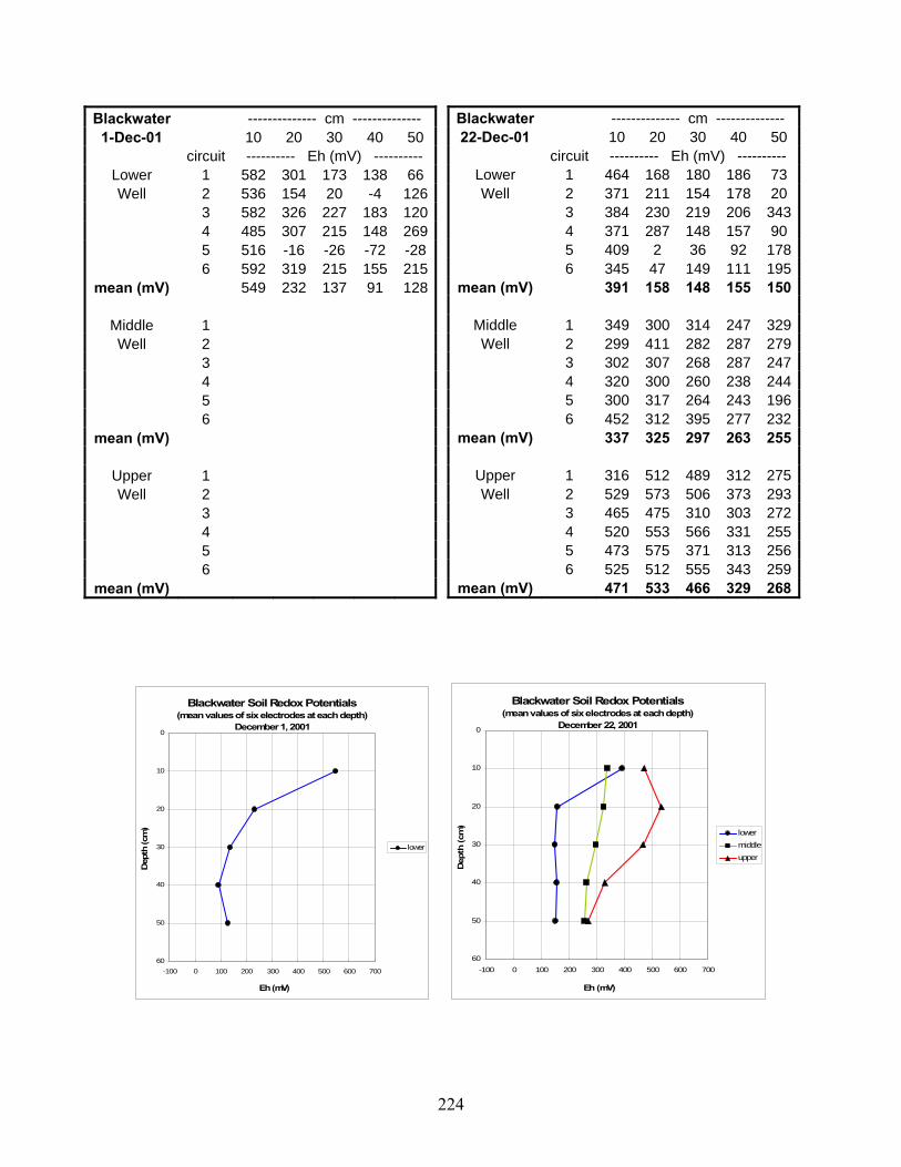
224
Blackwater -------------- cm -------------- 1-Dec-01 10 20 30 40 50
circuit ---------- Eh (mV) ---------- Lower 1 582 301 173 138 66 Well 2 536 154 20 -4 126
3 582 326 227 183 120 4 485 307 215 148 269 5 516 -16 -26 -72 -28 6 592 319 215 155 215
mean (mV) 549 232 137 91 128
Middle 1 Well 2
3 4 5 6
mean (mV)
Upper 1 Well 2
3 4 5 6
mean (mV)
Blackwater Soil Redox Potentials(mean values of six electrodes at each depth)
December 1, 20010
10
20
30
40
50
60-100 0 100 200 300 400 500 600 700
Eh (mV)
Dep
th (c
m)
lower
Blackwater Soil Redox Potentials(mean values of six electrodes at each depth)
December 22, 20010
10
20
30
40
50
60-100 0 100 200 300 400 500 600 700
Eh (mV)
Dep
th (c
m)
lowermiddleupper
Blackwater -------------- cm -------------- 22-Dec-01 10 20 30 40 50
circuit ---------- Eh (mV) ---------- Lower 1 464 168 180 186 73 Well 2 371 211 154 178 20
3 384 230 219 206 343 4 371 287 148 157 90 5 409 2 36 92 178 6 345 47 149 111 195
mean (mV) 391 158 148 155 150
Middle 1 349 300 314 247 329Well 2 299 411 282 287 279
3 302 307 268 287 247 4 320 300 260 238 244 5 300 317 264 243 196 6 452 312 395 277 232
mean (mV) 337 325 297 263 255
Upper 1 316 512 489 312 275Well 2 529 573 506 373 293
3 465 475 310 303 272 4 520 553 566 331 255 5 473 575 371 313 256 6 525 512 555 343 259
mean (mV) 471 533 466 329 268

225
Blackwater Soil Redox Potentials(mean values of six electrodes at each depth)
January 8, 20020
10
20
30
40
50
60-100 0 100 200 300 400 500 600 700
Eh (mV)
Dep
th (c
m)
lowermiddleupper
Blackwater Soil Redox Potentials(mean values of six electrodes at each depth)
February 1, 20020
10
20
30
40
50
60-100 0 100 200 300 400 500 600 700
Eh (mV)
Dep
th (c
m)
lowermiddleupper
Blackwater -------------- cm -------------- 1-Feb-02 10 20 30 40 50
circuit ---------- Eh (mV) ---------- Lower 1 349 283 205 205 229Well 2 373 330 222 239 269
3 249 247 225 216 225 4 361 233 211 189 243 5 263 236 229 232 235 6 253 233 183 207 150
mean (mV) 308 260 213 215 225
Middle 1 352 357 377 295 277Well 2 382 332 341 286 285
3 242 244 243 236 235 4 397 334 324 281 284 5 243 231 244 224 216 6 235 238 234 232 234
mean (mV) 309 289 294 259 255
Upper 1 370 243 270 259 257Well 2 416 337 354 320 273
3 317 244 241 242 229 4 491 355 352 324 273 5 330 222 238 247 227 6 290 231 225 267 215
mean (mV) 369 272 280 277 246
Blackwater -------------- cm -------------- 8-Jan-02 10 20 30 40 50
circuit ---------- Eh (mV) ---------- Lower 1 283 308 133 145 244Well 2 359 272 208 223 249
3 341 275 141 208 247 4 344 298 156 58 232 5 260 94 115 50 120 6 345 114 -40 156 221
mean (mV) 322 227 119 140 219
Middle 1 281 279 316 270 270Well 2 258 283 287 246 249
3 305 287 283 256 258 4 238 265 245 236 262 5 383 289 227 247 243 6 283 265 287 200 231
mean (mV) 291 278 274 243 252
Upper 1 480 542 398 293 269Well 2 473 503 322 280 251
3 304 383 304 247 244 4 450 529 702 297 259 5 504 481 451 295 255 6 526 563 419 353 259
mean (mV) 456 500 433 294 256

226
Blackwater Soil Redox Potentials(mean values of six electrodes at each depth)
February 16, 20020
10
20
30
40
50
60-100 0 100 200 300 400 500 600 700
Eh (mV)
Dep
th (c
m)
lowermiddleupper
Blackwater Soil Redox Potentials(mean values of six electrodes at each depth)
March 2, 20020
10
20
30
40
50
60-100 0 100 200 300 400 500 600 700
Eh (mV)
Dep
th (c
m)
lowermiddleupper
Blackwater -------------- cm -------------- 2-Mar-02 10 20 30 40 50
circuit ---------- Eh (mV) ---------- Lower 1 429 284 310 265 190Well 2 483 282 200 195 261
3 487 378 247 235 256 4 361 307 158 57 147 5 414 171 189 139 231 6 329 67 115 70 209
mean (mV) 417 248 203 160 216
Middle 1 459 351 359 285 294Well 2 283 267 289 239 267
3 382 316 327 278 257 4 377 336 280 244 227 5 320 408 300 283 286 6 341 345 315 269 263
mean (mV) 360 337 312 266 266
Upper 1 511 563 528 338 295Well 2 502 540 342 274 245
3 537 547 565 359 316 4 533 553 560 357 255 5 541 557 528 383 285 6 512 526 502 321 253
mean (mV) 523 548 504 339 275
Blackwater -------------- cm -------------- 16-Feb-02 10 20 30 40 50
circuit ---------- Eh (mV) ---------- Lower 1 346 304 119 3 198Well 2 244 302 208 175 250
3 373 336 -164 18 197 4 333 15 86 81 183 5 375 1 141 115 215 6 369 89 13 138 189
mean (mV) 340 175 67 88 205
Middle 1 358 279 245 276 269Well 2 300 230 271 257 252
3 355 298 286 263 267 4 397 310 247 239 245 5 380 263 419 225 217 6 336 220 271 225 221
mean (mV) 354 267 290 248 245
Upper 1 407 320 301 289 256Well 2 412 417 288 260 236
3 468 273 295 312 251 4 467 322 282 259 211 5 485 444 328 296 268 6 335 257 264 211 211
mean (mV) 429 339 293 271 239

227
Blackwater Soil Redox Potentials(mean values of six electrodes at each depth)
March 17, 20020
10
20
30
40
50
60-100 0 100 200 300 400 500 600 700
Eh (mV)
Dep
th (c
m)
lowermiddleupper
Blackwater Soil Redox Potentials(mean values of six electrodes at each depth)
March 28, 20020
10
20
30
40
50
60-100 0 100 200 300 400 500 600 700
Eh (mV)
Dep
th (c
m)
lowermiddleupper
Blackwater -------------- cm -------------- 28-Mar-02 10 20 30 40 50
circuit ---------- Eh (mV) ---------- Lower 1 365 97 149 250 210Well 2 392 354 129 237 230
3 359 173 79 237 215 4 311 56 137 77 48 5 153 91 139 171 219 6 250 60 123 178 169
mean (mV) 305 139 126 192 182
Middle 1 305 326 281 268 252Well 2 326 309 120 180 232
3 287 281 3 141 238 4 302 257 -11 184 231 5 281 303 259 266 269 6 265 277 212 190 236
mean (mV) 294 292 144 205 243
Upper 1 332 323 261 256 248Well 2 364 267 328 291 237
3 350 244 288 299 280 4 277 238 324 279 235 5 300 294 295 266 253 6 305 285 310 285 249
mean (mV) 321 275 301 279 250
Blackwater -------------- cm -------------- Mar 17, 2002 10 20 30 40 50
circuit ---------- Eh (mV) ---------- Lower 1 361 220 159 162 203Well 2 384 103 216 139 164
3 388 190 182 207 222 4 346 164 210 117 219 5 301 90 165 159 226 6 305 38 119 216 219
mean (mV) 348 134 175 167 209
Middle 1 359 300 279 297 308Well 2 370 301 273 303 296
3 371 332 229 269 306 4 436 275 267 325 243 5 414 277 224 351 249 6 369 286 258 316 224
mean (mV) 387 295 255 310 271
Upper 1 496 506 332 285 253Well 2 506 432 506 330 283
3 536 552 409 329 281 4 469 474 380 296 256 5 482 435 332 305 278 6 495 446 335 293 272
mean (mV) 497 474 382 306 271

228
Blackwater Soil Redox Potentials(mean values of six electrodes at each depth)
May 11, 20020
10
20
30
40
50
60-100 0 100 200 300 400 500 600 700
Eh (mV)
Dep
th (c
m)
lowermiddleupper
Blackwater Soil Redox Potentials(mean values of six electrodes at each depth)
May 25, 20020
10
20
30
40
50
60-100 0 100 200 300 400 500 600 700
Eh (mV)
Dep
th (c
m)
lowermiddleupper
Blackwater -------------- cm -------------- 25-May-02 10 20 30 40 50
circuit ---------- Eh (mV) ---------- Lower 1 474 305 190 207 169Well 2 358 306 217 238 123
3 422 324 194 237 94 4 285 261 200 244 149 5 293 249 204 210 186 6 285 176 162 251 157
mean (mV) 353 270 195 231 146
Middle 1 537 480 375 342 289Well 2 482 457 389 333 287
3 486 507 394 408 279 4 461 482 396 313 341 5 513 501 404 351 309 6 485 499 382 278 287
mean (mV) 494 488 390 338 299
Upper 1 529 486 344 434 303Well 2 491 509 585 454 311
3 495 510 464 327 289 4 454 492 404 319 295 5 526 535 494 313 279 6 519 521 554 329 281
mean (mV) 502 509 474 363 293
Blackwater -------------- cm -------------- 11-May-02 10 20 30 40 50
circuit ---------- Eh (mV) ---------- Lower 1 69 135 169 91 137Well 2 220 81 116 21 117
3 0 9 35 219 115 4 127 65 81 123 159 5 164 52 103 94 163 6 179 174 109 69 172
mean (mV) 127 86 102 103 144
Middle 1 311 335 320 273 275Well 2 310 388 340 252 249
3 320 269 313 225 254 4 295 253 227 186 174 5 264 276 304 268 232 6 301 320 262 217 197
mean (mV) 300 307 294 237 230
Upper 1 534 552 345 304 274Well 2 471 365 330 256 245
3 319 504 340 246 252 4 339 425 325 248 231 5 373 529 332 290 283 6 443 540 343 247 240
mean (mV) 413 486 336 265 254

229
Blackwater Soil Redox Potentials(mean values of six electrodes at each depth)
October 12, 20020
10
20
30
40
50
60-100 0 100 200 300 400 500 600 700
Eh (mV)
Dep
th (c
m)
lowermiddleupper
Blackwater Soil Redox Potentials(mean values of six electrodes at each depth)
November 30, 20020
10
20
30
40
50
60-100 0 100 200 300 400 500 600 700
Eh (mV)
Dep
th (c
m)
lowermiddleupper
Blackwater -------------- cm -------------- 12-Oct-02 10 20 30 40 50
circuit ---------- Eh (mV) ---------- Lower 1 279 211 205 230 224Well 2 217 233 213 224 198
3 243 250 243 251 243 4 276 251 202 247 226 5 285 278 182 249 222 6 222 190 231 246 246
mean (mV) 254 236 213 241 227
Middle 1 271 262 255 308 226Well 2 296 286 270 298 238
3 261 247 261 283 234 4 276 305 259 292 224 5 284 270 267 295 228 6 273 275 263 304 232
mean (mV) 277 274 263 297 230
Upper 1 308 292 293 226 230Well 2 363 297 349 251 267
3 408 292 304 194 283 4 354 299 272 272 285 5 414 362 332 268 291 6 325 342 274 349 302
mean (mV) 362 314 304 260 276
Blackwater -------------- cm -------------- 30-Nov-02 10 20 30 40 50
circuit ---------- Eh (mV) ---------- Lower 1 170 223 220 235 237Well 2 87 208 217 192 225
3 293 239 247 240 240 4 121 227 254 244 231 5 148 235 243 235 235 6 115 215 272 255 243
mean (mV) 156 225 242 234 235
Middle 1 223 224 267 247 289Well 2 131 235 240 223 291
3 190 249 250 248 278 4 155 247 252 249 221 5 152 231 251 239 244 6 250 250 288 279 251
mean (mV) 184 239 258 248 262
Upper 1 262 286 251 307 252Well 2 211 261 245 296 286
3 232 313 300 273 304 4 300 266 288 268 260 5 244 267 242 225 231 6 291 307 287 294 287
mean (mV) 257 283 269 277 270

230
Blackwater Soil Redox Potentials(mean values of six electrodes at each depth)
January 11, 20030
10
20
30
40
50
60-100 0 100 200 300 400 500 600 700
Eh (mV)
Dep
th (c
m)
lowermiddleupper
Blackwater Soil Redox Potentials(mean values of six electrodes at each depth)
January 25, 20030
10
20
30
40
50
60-100 0 100 200 300 400 500 600 700
Eh (mV)
Dep
th (c
m)
lowermiddleupper
Blackwater -------------- cm -------------- 25-Jan-03 10 20 30 40 50
circuit ---------- Eh (mV) ---------- Lower 1 156 199 221 233 231Well 2 90 141 221 223 222
3 159 160 243 232 231 4 125 195 236 231 229 5 59 127 177 225 234 6 46 169 52 187 201
mean (mV) 106 165 192 222 225
Middle 1 182 244 118 249Well 2 201 218 183 243
3 248 274 271 262 4 193 231 243 230 5 206 276 301 259 6 167 316 258 211
mean (mV) 200 260 229 242
Upper 1 296 233 251 245 247Well 2 370 353 277 267 275
3 478 300 277 300 294 4 348 340 251 234 243 5 214 307 271 264 256 6 380 256 234 233 243
mean (mV) 348 298 260 257 260
Blackwater -------------- cm -------------- 11-Jan-03 10 20 30 40 50
circuit ---------- Eh (mV) ---------- Lower 1 105 216 186 197 212Well 2 142 -74 191 214 224
3 85 96 204 202 221 4 66 98 227 229 210 5 27 78 186 237 220 6 22 85 209 189 215
mean (mV) 75 83 201 211 217
Middle 1 277 306 231 307 332Well 2 289 265 245 198 263
3 231 213 243 252 244 4 231 199 227 247 226 5 193 206 242 305 267 6 213 194 229 284 259
mean (mV) 239 231 236 266 265
Upper 1 204 253 234 236 274Well 2 108 239 264 243 257
3 220 274 261 230 255 4 282 247 243 204 241 5 306 276 272 255 285 6
mean (mV) 224 258 255 234 262

231
Blackwater Soil Redox Potentials(mean values of six electrodes at each depth)
February 9, 20030
10
20
30
40
50
60-100 0 100 200 300 400 500 600 700
Eh (mV)
Dep
th (c
m)
lowermiddleupper
Blackwater Soil Redox Potentials(mean values of six electrodes at each depth)
March 1, 20030
10
20
30
40
50
60-100 0 100 200 300 400 500 600 700
Eh (mV)
Dep
th (c
m)
lowermiddleupper
Blackwater -------------- cm -------------- 1-Mar-03 10 20 30 40 50
circuit ---------- Eh (mV) ---------- Lower 1 249 251 241 255 226Well 2 152 228 259 242 223
3 291 261 256 256 234 4 262 244 253 251 230 5 202 129 234 216 99 6 261 225 265 261 166
mean (mV) 236 223 251 247 196
Middle 1 265 272 296 287 283Well 2 265 241 295 302 333
3 304 279 316 318 291 4 278 294 288 334 249 5 224 239 257 295 338 6 260 289 301 284 346
mean (mV) 266 269 292 303 307
Upper 1 297 267 244 247 251Well 2 312 209 242 263 181
3 266 259 252 256 254 4 298 292 252 259 248 5 273 249 235 238 242 6 230 246 243 239 245
mean (mV) 279 254 245 250 237
Blackwater -------------- cm -------------- 9-Feb-03 10 20 30 40 50
circuit ---------- Eh (mV) ---------- Lower 1 29 231 208 224 211Well 2 49 230 200 224 216
3 96 197 172 166 109 4 94 187 224 228 211 5 59 169 228 233 207 6
mean (mV) 65 203 206 215 191
Middle 1 256 250 251 211 209Well 2 162 243 266 234 244
3 188 167 154 164 233 4 132 227 263 219 239 5 259 236 272 250 228 6
mean (mV) 199 225 241 216 231
Upper 1 299 269 203 235 247Well 2 239 211 215 229 231
3 380 370 203 186 198 4 268 251 210 279 247 5 256 281 234 262 243 6
mean (mV) 288 276 213 238 233

232
Blackwater Soil Redox Potentials(mean values of six electrodes at each depth)
March 24, 20030
10
20
30
40
50
60-100 0 100 200 300 400 500 600 700
Eh (mV)
Dep
th (c
m)
lowermiddleupper
Blackwater Soil Redox Potentials(mean values of six electrodes at each depth)
April 4, 20030
10
20
30
40
50
60-100 0 100 200 300 400 500 600 700
Eh (mV)
Dep
th (c
m)
lowermiddleupper
Blackwater -------------- cm -------------- 4-Apr-03 10 20 30 40 50
circuit ---------- Eh (mV) ---------- Lower 1 -54 -23 154 188 194Well 2
3 4 50 192 221 228 4 -43 1 175 205 121 5 9 91 77 185 199 6 -40 81 133 195 204
mean (mV) -25 40 146 199 189
Middle 1 75 128 248 216 277Well 2
3 35 141 277 304 271 4 32 105 257 200 199 5 185 165 244 244 218 6 173 145 275 250 237
mean (mV) 100 137 260 243 240
Upper 1 186 218 174 211 190Well 2
3 245 290 190 223 199 4 179 108 159 194 195 5 176 181 181 217 209 6 184 177 164 221 205
mean (mV) 194 195 174 213 200
Blackwater -------------- cm -------------- 24-Mar-03 10 20 30 40 50
circuit ---------- Eh (mV) ---------- Lower 1 96 132 90 184 200Well 2
3 152 174 174 219 237 4 62 69 153 167 178 5 59 156 148 170 204 6 147 163 173 204 229
mean (mV) 103 139 148 189 210
Middle 1 253 289 260 252 307Well 2
3 265 309 320 237 244 4 254 229 262 233 285 5 283 137 286 237 279 6 272 109 270 244 277
mean (mV) 265 215 280 241 278
Upper 1 279 271 214 205 209Well 2
3 241 238 236 210 222 4 263 269 234 231 247 5 312 312 281 242 233 6 286 244 259 244 246
mean (mV) 276 267 245 226 231

233
Blackwater Soil Redox Potentials(mean values of six electrodes at each depth)
April 19, 20030
10
20
30
40
50
60-100 0 100 200 300 400 500 600 700
Eh (mV)
Dep
th (c
m)
lowermiddleupper
Blackwater Soil Redox Potentials(mean values of six electrodes at each depth)
May 2, 20030
10
20
30
40
50
60-100 0 100 200 300 400 500 600 700
Eh (mV)
Dep
th (c
m)
lowermiddleupper
Blackwater -------------- cm -------------- 19-Apr-03 10 20 30 40 50
circuit ---------- Eh (mV) ---------- Lower 1 22 72 176 188 189Well 2 -8 31 70 166 52
3 42 61 223 229 205 4 10 24 224 228 221 5 10 -7 157 194 196 6
mean (mV) 15 36 170 201 173
Middle 1 196 227 316 281 270Well 2 130 123 265 238 311
3 84 122 242 212 326 4 93 163 295 247 272 5 183 212 270 244 233 6
mean (mV) 137 169 278 244 282
Upper 1 203 244 195 196 208Well 2 207 226 191 222 224
3 155 228 223 234 250 4 214 109 198 224 229 5 189 236 212 227 234 6
mean (mV) 194 209 204 221 229
Blackwater -------------- cm -------------- 2-May-03 10 20 30 40 50
circuit ---------- Eh (mV) ---------- Lower 1 63 129 160 199 177Well 2 98 126 73 188 178
3 54 145 151 92 106 4 61 73 81 200 192 5 7 44 97 146 144 6
mean (mV) 57 103 112 165 159
Middle 1 91 73 268 236 252Well 2 281 252 319 196 290
3 56 83 278 229 251 4 92 208 258 241 295 5 16 84 255 215 318 6
mean (mV) 107 140 276 223 281
Upper 1 239 229 201 185 180Well 2 325 103 184 219 206
3 238 235 201 232 231 4 302 282 157 186 204 5 207 200 171 237 240 6
mean (mV) 262 210 183 212 212

234
Blackwater Soil Redox Potentials(mean values of six electrodes at each depth)
May 19, 20030
10
20
30
40
50
60-100 0 100 200 300 400 500 600 700
Eh (mV)
Dep
th (c
m)
lowermiddleupper
Blackwater Soil Redox Potentials(mean values of six electrodes at each depth)
June 1, 20030
10
20
30
40
50
60-100 0 100 200 300 400 500 600 700
Eh (mV)
Dep
th (c
m)
lowermiddleupper
Blackwater -------------- cm -------------- 1-Jun-03 10 20 30 40 50
circuit ---------- Eh (mV) ---------- Lower 1 11 174 151 189 196Well 2 41 158 109 186 173
3 50 328 150 181 191 4 61 86 172 127 221 5 88 165 194 218 233 6 128 193 203 230 242
mean (mV) 63 184 163 189 209
Middle 1 236 240 235 264 263Well 2 258 217 190 244 267
3 196 230 213 251 221 4 259 283 277 271 291 5 296 199 266 277 292 6 334 316 292 306 293
mean (mV) 263 248 246 269 271
Upper 1 234 203 180 169 178Well 2 240 210 165 202 192
3 237 191 178 184 218 4 282 300 226 258 262 5 289 256 217 262 267 6 334 284 279 257 274
mean (mV) 269 241 208 222 232
Blackwater -------------- cm -------------- 19-May-03 10 20 30 40 50
circuit ---------- Eh (mV) ---------- Lower 1 -22 80 189 180 95 Well 2 31 96 199 153 41
3 12 60 178 170 152 4 -45 53 60 94 139 5 35 66 198 142 116 6
mean (mV) 2 71 165 148 109
Middle 1 131 169 240 243 282Well 2 185 208 260 226 268
3 186 209 245 279 273 4 162 212 233 224 295 5 188 189 210 182 233 6
mean (mV) 170 197 238 231 270
Upper 1 304 216 245 219 244Well 2 264 265 244 233 219
3 262 252 241 241 228 4 249 371 271 206 255 5 275 231 224 166 239 6
mean (mV) 271 267 245 213 237

235
Blackwater Soil Redox Potentials(mean values of six electrodes at each depth)
June 22, 20030
10
20
30
40
50
60-100 0 100 200 300 400 500 600 700
Eh (mV)
Dep
th (c
m)
lowermiddleupper
Blackwater Soil Redox Potentials(mean values of six electrodes at each depth)
July 17, 20030
10
20
30
40
50
60-100 0 100 200 300 400 500 600 700
Eh (mV)
Dep
th (c
m)
lowermiddleupper
Blackwater -------------- cm -------------- 17-Jul-03 10 20 30 40 50
circuit ---------- Eh (mV) ---------- Lower 1 Well 2 59 13 17 121 192
3 37 32 130 184 214 4 187 139 176 244 290 5 36 14 73 182 233 6 172 195 215 294 324
mean (mV) 98 79 122 205 251
Middle 1 Well 2 248 232 254 239 274
3 249 269 275 250 259 4 230 236 274 310 284 5 332 286 333 342 290 6 360 422 397 410 371
mean (mV) 284 289 307 310 296
Upper 1 Well 2 208 289 253 181 230
3 314 353 265 273 262 4 270 256 246 302 265 5 372 353 330 286 271 6 279 327 356 332 351
mean (mV) 289 316 290 275 276
Blackwater -------------- cm -------------- 22-Jun-03 10 20 30 40 50
circuit ---------- Eh (mV) ---------- Lower 1 Well 2 13 8 173 181 204
3 3 28 169 178 198 4 -12 58 164 193 205 5 17 49 153 222 230 6 -60 4 161 196 220
mean (mV) -8 29 164 194 211
Middle 1 Well 2 241 233 247 248 297
3 242 273 289 284 340 4 5 264 307 353 346 392 6 332 352 362 345 356
mean (mV) 270 291 313 306 346
Upper 1 Well 2 202 240 204 212 227
3 248 267 241 242 256 4 5 235 296 287 287 282 6 284 318 308 320 323
mean (mV) 242 280 260 265 272

236
Blackwater Soil Redox Potentials(mean values of six electrodes at each depth)
August 19, 20030
10
20
30
40
50
60-100 0 100 200 300 400 500 600 700
Eh (mV)
Dep
th (c
m)
lowermiddleupper
Blackwater -------------- cm -------------- 19-Aug-03 10 20 30 40 50
circuit ---------- Eh (mV) ---------- Lower 1 Well 2 17 22 67 36 53
3 93 54 112 50 202 4 129 139 133 115 246 5 190 193 156 200 285 6 187 216 191 208 285
mean (mV) 123 125 132 122 214
Middle 1 Well 2 122 217 217 294 240
3 115 174 253 276 284 4 93 160 185 299 244 5 110 214 244 276 225 6 216
mean (mV) 131 191 225 286 248
Upper 1 Well 2 164 178 125 199 243
3 182 170 172 193 204 4 167 204 120 223 238 5 110 188 137 188 233 6
mean (mV) 156 185 139 201 230

237
Isle of Wight -------------- cm -------------- 15-Feb-01 10 20 30 40 50
circuit ---------- Eh (mV) ---------- Lower 1 492 389 328 364 238Well 2 451 375 324 270 279
3 459 417 301 222 209 4 475 361 271 272 161 5 442 381 430 337 202 6
mean (mV) 464 385 331 293 218
Middle 1 621 619 618 592 518Well 2 635 635 621 598 522
3 639 616 609 553 479 4 613 620 626 516 426 5 449 619 626 400 369 6
mean (mV) 591 622 620 532 463
Upper 1 556 585 626 616 617Well 2 592 611 626 608 627
3 609 590 620 627 610 4 578 620 627 620 625 5 635 614 612 617 597 6
mean (mV) 594 604 622 618 615
Isle of Wight Soil Redox Potentials(mean values of six electrodes at each depth)
February 15, 20010
10
20
30
40
50
60-100 0 100 200 300 400 500 600 700
Eh (mV)
Dep
th (c
m)
lowermiddleupper
Isle of Wight Soil Redox Potentials(mean values of six electrodes at each depth)
February 27, 20010
10
20
30
40
50
60-100 0 100 200 300 400 500 600 700
Eh (mV)
Dep
th (c
m)
lowermiddleupper
Isle of Wight -------------- cm -------------- 27-Feb-01 10 20 30 40 50
circuit ---------- Eh (mV) ---------- Lower 1 355 299 442 214 221Well 2 357 317 254 159 256
3 293 259 189 131 88 4 418 404 381 302 179 5 409 395 231 267 194 6 444 437 264 300 211
mean (mV) 379 352 294 229 192
Middle 1 591 572 585 544 521Well 2 551 585 574 422 324
3 501 521 503 309 277 4 441 495 381 264 222 5 486 524 487 351 300 6 430 508 359 320 273
mean (mV) 500 534 482 368 320
Upper 1 423 361 591 594 568Well 2 385 318 569 605 558
3 402 451 564 599 600 4 419 352 533 588 581 5 396 306 543 593 561 6 505 282 569 592 596
mean (mV) 422 345 562 595 577

238
Isle of Wight -------------- cm -------------- 19-Mar-01 10 20 30 40 50
circuit ---------- Eh (mV) ---------- Lower 1 395 253 274 204 251Well 2 373 257 210 87 86
3 229 155 116 107 115 4 369 307 227 273 160 5 324 227 129 138 72 6 372 383 272 278 264
mean (mV) 344 264 205 181 158
Middle 1 397 514 410 349 325Well 2 346 390 325 318 310
3 210 173 190 196 194 4 378 322 312 310 340 5 250 242 244 230 206 6 316 346 311 303 306
mean (mV) 316 331 299 284 280
Upper 1 369 335 403 506 554Well 2 448 313 497 524 597
3 308 259 408 474 500 4 349 322 297 490 539 5 373 355 427 538 549 6 318 329 511 584 567
mean (mV) 361 319 424 519 551
Isle of Wight Soil Redox Potentials(mean values of six electrodes at each depth)
March 19, 20010
10
20
30
40
50
60-100 0 100 200 300 400 500 600 700
Eh (mV)
Dep
th (c
m)
lowermiddleupper
Isle of Wight Soil Redox Potentials(mean values of six electrodes at each depth)
April 3, 20010
10
20
30
40
50
60-100 0 100 200 300 400 500 600 700
Eh (mV)
Dep
th (c
m)
lowermiddleupper
Isle of Wight -------------- cm -------------- 3-Apr-01 10 20 30 40 50
circuit ---------- Eh (mV) ---------- Lower 1 326 329 346 146 256Well 2 344 266 362 115 92
3 57 124 93 159 34 4 306 276 271 187 67 5 284 239 219 156 136 6 375 310 366 219 217
mean (mV) 282 257 276 164 134
Middle 1 594 415 307 297 301Well 2 598 441 333 312 317
3 263 182 161 127 179 4 485 364 339 334 277 5 405 286 278 290 281 6 390 357 317 339 313
mean (mV) 456 341 289 283 278
Upper 1 422 286 312 291 389Well 2 397 236 310 295 179
3 188 123 180 195 113 4 382 335 340 319 260 5 385 244 285 275 175 6 384 316 308 332 253
mean (mV) 360 257 289 285 228

239
Isle of WightSoil Redox Potentials(mean values of six electrodes at each depth)
April 22, 20010
10
20
30
40
50
60-100 0 100 200 300 400 500 600 700
Eh (mV)
Dep
th (c
m)
lowermiddleupper
Isle of Wight Soil Redox Potentials(mean values of six electrodes at each depth)
May 3, 20010
10
20
30
40
50
60-100 0 100 200 300 400 500 600 700
Eh (mV)
Dep
th (c
m)
lowermiddleupper
Isle of Wight -------------- cm -------------- 22-Apr-01 10 20 30 40 50
circuit ---------- Eh (mV) ---------- Lower 1 281 258 304 165 125Well 2 199 224 271 167 143
3 287 308 287 199 174 4 292 277 272 167 142 5 322 334 336 247 206 6 163 143 277 184 128
mean (mV) 257 257 291 188 153
Middle 1 313 239 277 252 244Well 2 255 262 298 264 320
3 362 287 312 273 318 4 332 272 260 261 234 5 304 303 323 309 319 6 179 136 105 136 187
mean (mV) 291 250 263 249 270
Upper 1 423 291 301 296 308Well 2 339 318 276 270 269
3 354 332 319 294 269 4 235 169 220 213 178 5 344 328 340 325 283 6 224 187 179 152 139
mean (mV) 320 271 273 258 241
Isle of Wight -------------- cm -------------- 3-May-01 10 20 30 40 50
circuit ---------- Eh (mV) ---------- Lower 1 337 288 287 250 241Well 2 355 232 184 196 177
3 483 281 272 249 238 4 296 334 231 204 179 5 313 305 309 266 253 6 481 299 250 199 231
mean (mV) 378 290 256 227 220
Middle 1 395 314 280 256 274Well 2 167 414 458 242 281
3 349 282 247 254 229 4 501 208 528 214 286 5 515 526 609 305 325 6 427 598 337 276 233
mean (mV) 392 390 410 258 271
Upper 1 574 119 272 300 280Well 2 329 258 277 263 182
3 363 280 280 237 281 4 353 372 326 272 241 5 514 337 327 330 280 6 487 280 304 297 244
mean (mV) 437 274 298 283 251

240
Isle of Wight -------------- cm -------------- 17-May-01 10 20 30 40 50
circuit ---------- Eh (mV) ---------- Lower 1 560 578 538 312 345Well 2 529 524 339 297 380
3 529 572 479 315 258 4 534 533 474 261 207 5 547 537 345 315 270 6 531 530 312 283 255
mean (mV) 538 546 415 297 286
Middle 1 611 624 638 624 559Well 2 563 600 630 628 546
3 551 538 625 650 628 4 567 590 623 638 641 5 559 607 636 652 650 6 592 620 641 604 615
mean (mV) 574 597 632 633 607
Upper 1 616 622 628 599 306Well 2 592 606 628 642 229
3 593 619 648 653 262 4 610 623 642 617 213 5 556 618 551 624 316 6 613 624 659 661 404
mean (mV) 597 619 626 633 288
Isle of Wight Soil Redox Potentials(mean values of six electrodes at each depth)
May 17, 20010
10
20
30
40
50
60-100 0 100 200 300 400 500 600 700
Eh (mV)
Dep
th (c
m)
lowermiddleupper
Isle of Wight Soil Redox Potentials(mean values of six electrodes at each depth)
May 30, 20010
10
20
30
40
50
60-100 0 100 200 300 400 500 600 700
Eh (mV)
Dep
th (c
m)
lowermiddleupper
Isle of Wight -------------- cm -------------- 30-May-01 10 20 30 40 50
circuit ---------- Eh (mV) ---------- Lower 1 314 306 236 267 163Well 2 315 334 262 258 175
3 356 330 283 314 201 4 337 308 207 234 146 5 368 321 188 290 236 6 319 303 223 196 160
mean (mV) 335 317 233 260 180
Middle 1 574 514 596 623 361Well 2 366 529 580 584 366
3 479 552 614 606 401 4 366 526 595 615 582 5 426 563 615 623 447 6 375 477 596 586 536
mean (mV) 431 527 599 606 449
Upper 1 412 288 562 384 192Well 2 357 283 590 272 174
3 388 355 568 350 209 4 382 454 368 285 291 5 462 495 322 299 204 6 415 343 451 550 285
mean (mV) 403 370 477 357 226
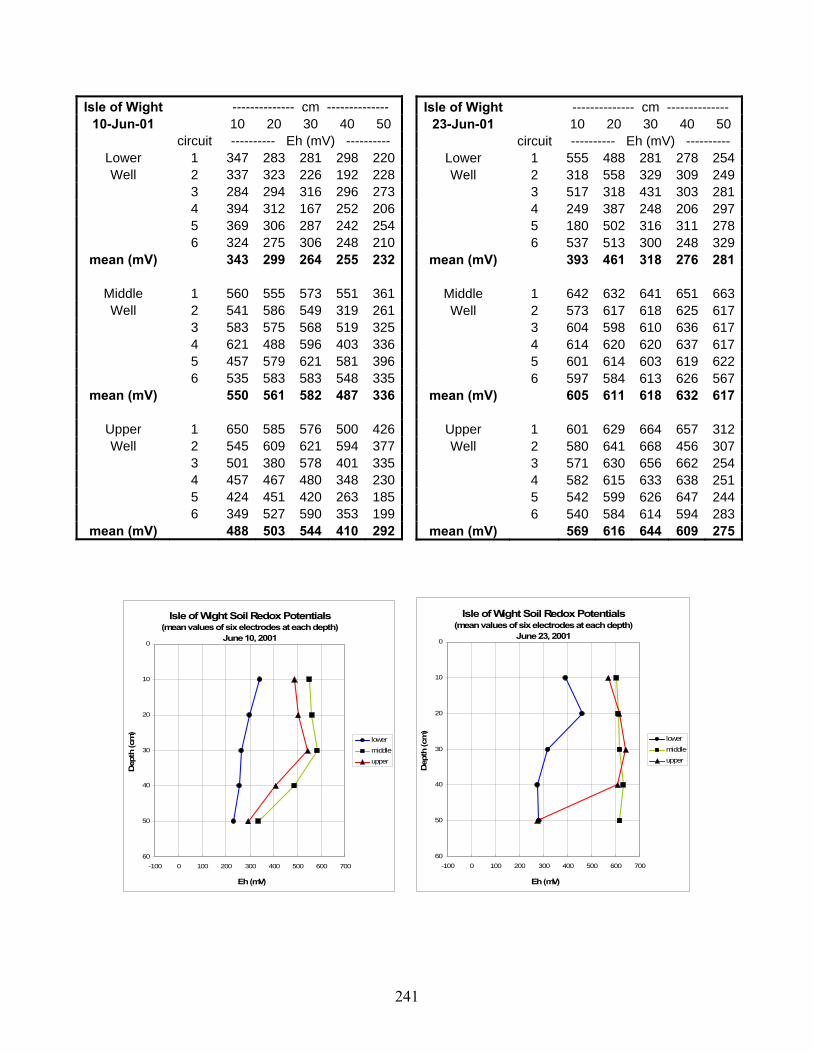
241
Isle of Wight -------------- cm -------------- 10-Jun-01 10 20 30 40 50
circuit ---------- Eh (mV) ---------- Lower 1 347 283 281 298 220Well 2 337 323 226 192 228
3 284 294 316 296 273 4 394 312 167 252 206 5 369 306 287 242 254 6 324 275 306 248 210
mean (mV) 343 299 264 255 232
Middle 1 560 555 573 551 361Well 2 541 586 549 319 261
3 583 575 568 519 325 4 621 488 596 403 336 5 457 579 621 581 396 6 535 583 583 548 335
mean (mV) 550 561 582 487 336
Upper 1 650 585 576 500 426Well 2 545 609 621 594 377
3 501 380 578 401 335 4 457 467 480 348 230 5 424 451 420 263 185 6 349 527 590 353 199
mean (mV) 488 503 544 410 292
Isle of Wight Soil Redox Potentials(mean values of six electrodes at each depth)
June 10, 20010
10
20
30
40
50
60-100 0 100 200 300 400 500 600 700
Eh (mV)
Dep
th (c
m)
lowermiddleupper
Isle of Wight Soil Redox Potentials(mean values of six electrodes at each depth)
June 23, 20010
10
20
30
40
50
60-100 0 100 200 300 400 500 600 700
Eh (mV)
Dep
th (c
m)
lowermiddleupper
Isle of Wight -------------- cm -------------- 23-Jun-01 10 20 30 40 50
circuit ---------- Eh (mV) ---------- Lower 1 555 488 281 278 254Well 2 318 558 329 309 249
3 517 318 431 303 281 4 249 387 248 206 297 5 180 502 316 311 278 6 537 513 300 248 329
mean (mV) 393 461 318 276 281
Middle 1 642 632 641 651 663Well 2 573 617 618 625 617
3 604 598 610 636 617 4 614 620 620 637 617 5 601 614 603 619 622 6 597 584 613 626 567
mean (mV) 605 611 618 632 617
Upper 1 601 629 664 657 312Well 2 580 641 668 456 307
3 571 630 656 662 254 4 582 615 633 638 251 5 542 599 626 647 244 6 540 584 614 594 283
mean (mV) 569 616 644 609 275

242
Isle of Wight -------------- cm -------------- 7-Jul-01 10 20 30 40 50
circuit ---------- Eh (mV) ---------- Lower 1 471 499 301 230 161Well 2 548 528 465 317 236
3 288 565 528 345 252 4 507 543 443 397 244 5 435 546 472 309 214 6 535 560 498 291 251
mean (mV) 464 540 451 315 226
Middle 1 591 563 572 584 566Well 2 633 627 637 642 623
3 628 620 640 652 655 4 613 621 597 630 654 5 594 622 640 650 649 6 606 606 625 642 648
mean (mV) 611 610 619 633 633
Upper 1 577 599 627 652 648Well 2 607 646 659 670 670
3 609 628 657 660 655 4 591 595 625 648 646 5 591 629 641 650 624 6 575 601 579 632 652
mean (mV) 592 616 631 652 649
Isle of Wight Soil Redox Potentials(mean values of six electrodes at each depth)
July 7, 20010
10
20
30
40
50
60-100 0 100 200 300 400 500 600 700
Eh (mV)
Dep
th (c
m)
lowermiddleupper
Isle of Wight Soil Redox Potentials(mean values of six electrodes at each depth)
July 19, 20010
10
20
30
40
50
60-100 0 100 200 300 400 500 600 700
Eh (mV)
Dep
th (c
m)
lowermiddleupper
Isle of Wight -------------- cm -------------- 19-Jul-01 10 20 30 40 50
circuit ---------- Eh (mV) ---------- Lower 1 507 545 584 568 513Well 2 498 569 572 356 256
3 527 589 601 594 327 4 509 563 603 314 258 5 551 570 596 344 261 6 535 602 604 569 554
mean (mV) 521 573 593 458 362
Middle 1 604 571 618 612 640Well 2 643 643 643 661 625
3 625 638 643 661 642 4 600 624 630 649 663 5 596 613 637 652 665 6 603 576 636 644 669
mean (mV) 612 611 635 647 651
Upper 1 634 660 665 686 665Well 2 639 657 664 676 670
3 644 654 656 678 660 4 606 610 515 599 628 5 633 645 588 651 677 6 611 660 669 681 688
mean (mV) 628 648 626 662 665

243
Isle of Wight -------------- cm -------------- 2-Sep-01 10 20 30 40 50
circuit ---------- Eh (mV) ---------- Lower 1 564 582 606 450 388Well 2 557 573 598 612 379
3 564 604 623 600 337 4 559 594 607 310 312 5 597 618 624 377 302 6 593 619 615 611 315
mean (mV) 572 598 612 493 339
Middle 1 Well 2
3 4 5 6
mean (mV)
Upper 1 Well 2
3 4 5 6
mean (mV)
Isle of Wight Soil Redox Potentials(mean values of six electrodes at each depth)
September 2, 20010
10
20
30
40
50
60-100 0 100 200 300 400 500 600 700
Eh (mV)
Dep
th (c
m)
lowermiddleupper
Isle of Wight Soil Redox Potentials(mean values of six electrodes at each depth)
September 28, 20010
10
20
30
40
50
60-100 0 100 200 300 400 500 600 700
Eh (mV)
Dep
th (c
m)
lowermiddleupper
Isle of Wight -------------- cm -------------- 28-Sep-01 10 20 30 40 50
circuit ---------- Eh (mV) ---------- Lower 1 467 525 544 562 217Well 2 563 588 261
3 523 548 573 512 249 4 503 547 488 556 280 5 493 526 536 346 315 6 531 554 571 519 277
mean (mV) 503 540 546 514 267
Middle 1 582 600 600 642 651Well 2 632 530 615 649 648
3 618 619 635 656 657 4 597 617 625 648 651 5 591 629 626 652 656 6 610 619 641 659 666
mean (mV) 605 602 624 651 655
Upper 1 586 611 622 625 617Well 2
3 4 5 6 612 646 636 664 665
mean (mV) 599 629 629 645 641

244
Isle of Wight -------------- cm -------------- 15-Dec-01 10 20 30 40 50
circuit ---------- Eh (mV) ---------- Lower 1 507 522 542 539 302Well 2 461 528 535 530 311
3 473 531 555 546 360 4 435 513 538 543 547 5 438 514 467 532 308 6 512 516 534 507 221
mean (mV) 471 521 529 533 342
Middle 1 547 559 573 580 596Well 2 569 546 566 596 605
3 561 576 572 537 590 4 559 593 586 565 602 5 559 551 573 582 607 6 573 590 583 596 611
mean (mV) 561 569 576 576 602
Upper 1 626 661 664 689 675Well 2 639 639 603 662 654
3 633 655 651 668 662 4 630 661 657 667 655 5 619 641 664 677 671 6 615 569 602 636 642
mean (mV) 627 638 640 667 660
Isle of Wight Soil Redox Potentials(mean values of six electrodes at each depth)
December 15, 20010
10
20
30
40
50
60-100 0 100 200 300 400 500 600 700
Eh (mV)
Dep
th (c
m)
lowermiddleupper
Isle of Wight Soil Redox Potentials(mean values of six electrodes at each depth)
January 8, 20020
10
20
30
40
50
60-100 0 100 200 300 400 500 600 700
Eh (mV)
Dep
th (c
m)
lowermiddleupper
Isle of Wight -------------- cm -------------- 8-Jan-02 10 20 30 40 50
circuit ---------- Eh (mV) ---------- Lower 1 521 539 549 526 495Well 2 533 536 540 549 423
3 503 416 398 383 347 4 532 532 546 554 310 5 503 525 537 554 427 6 524 543 549 550 244
mean (mV) 519 515 520 519 374
Middle 1 548 559 571 573 592Well 2 550 572 583 583 583
3 395 445 459 467 444 4 550 567 578 582 582 5 535 561 569 580 581 6 546 581 561 585 599
mean (mV) 521 548 554 562 564
Upper 1 611 569 615 604 632Well 2 616 608 642 672 662
3 473 525 530 538 569 4 622 639 657 647 662 5 616 644 659 373 661 6 591 652 651 378 664
mean (mV) 588 606 626 535 642

245
Isle of Wight -------------- cm -------------- 1-Feb-02 10 20 30 40 50
circuit ---------- Eh (mV) ---------- Lower 1 470 466 390 337 266Well 2 524 502 426 395 265
3 402 486 432 268 201 4 504 513 505 360 284 5 426 410 453 365 257 6 393 351 479 457 273
mean (mV) 453 455 448 364 258
Middle 1 515 515 510 511 490Well 2 569 557 561 568 559
3 484 505 506 505 489 4 559 575 565 584 575 5 521 536 549 568 562 6 536 553 568 578 555
mean (mV) 531 540 543 552 538
Upper 1 579 594 596 590 584Well 2 633 637 628 646 630
3 525 554 563 577 564 4 638 622 648 628 632 5 625 641 653 658 644 6 615 622 649 626 623
mean (mV) 603 612 623 621 613
Isle of Wight Soil Redox Potentials(mean values of six electrodes at each depth)
February 1, 20020
10
20
30
40
50
60-100 0 100 200 300 400 500 600 700
Eh (mV)
Dep
th (c
m)
lowermiddleupper
Isle of Wight Soil Redox Potentials(mean values of six electrodes at each depth)
February 16, 20020
10
20
30
40
50
60-100 0 100 200 300 400 500 600 700
Eh (mV)
Dep
th (c
m)
lowermiddleupper
Isle of Wight -------------- cm -------------- 16-Feb-02 10 20 30 40 50
circuit ---------- Eh (mV) ---------- Lower 1 494 452 324 287 255Well 2 427 377 269 250 252
3 514 512 361 321 284 4 511 477 485 360 284 5 519 503 497 287 253 6 443 515 493 267 266
mean (mV) 485 473 405 295 266
Middle 1 562 585 581 563 514Well 2 475 501 446 462 395
3 569 568 579 576 536 4 545 480 545 567 531 5 548 563 561 566 550 6 559 565 566 577 541
mean (mV) 543 544 546 552 511
Upper 1 628 644 648 647 657Well 2 530 551 543 559 563
3 607 568 640 617 652 4 589 645 648 640 633 5 627 639 652 656 654 6 630 650 654 656 666
mean (mV) 602 616 631 629 638

246
Isle of Wight -------------- cm -------------- 2-Mar-02 10 20 30 40 50
circuit ---------- Eh (mV) ---------- Lower 1 524 537 353 319 270Well 2 499 531 337 279 244
3 515 505 343 304 269 4 508 507 444 269 236 5 529 533 347 296 260 6 497 518 425 313 247
mean (mV) 512 522 375 297 254
Middle 1 573 584 573 564 429Well 2 459 471 474 466 404
3 570 582 585 584 524 4 572 572 576 596 546 5 565 571 596 595 497 6 575 574 595 601 543
mean (mV) 552 559 567 568 491
Upper 1 647 651 672 669 648Well 2 636 646 656 648 656
3 620 638 631 655 646 4 642 633 639 645 644 5 638 654 658 640 635 6 635 652 656 646 645
mean (mV) 636 646 652 651 646
Isle of Wight Soil Redox Potentials(mean values of six electrodes at each depth)
March 2, 20020
10
20
30
40
50
60-100 0 100 200 300 400 500 600 700
Eh (mV)
Dep
th (c
m)
lowermiddleupper
Isle of Wight Soil Redox Potentials(mean values of six electrodes at each depth)
March 17, 20020
10
20
30
40
50
60-100 0 100 200 300 400 500 600 700
Eh (mV)
Dep
th (c
m)
lowermiddleupper
Isle of Wight -------------- cm -------------- 17-Mar-02 10 20 30 40 50
circuit ---------- Eh (mV) ---------- Lower 1 322 402 299 265 274Well 2 338 435 312 285 281
3 321 428 302 282 283 4 318 420 318 276 279 5 332 415 310 288 285 6 335 407 307 273 276
mean (mV) 328 418 308 278 280
Middle 1 502 595 591 556 382Well 2 505 581 582 546 333
3 488 603 597 556 346 4 524 588 595 543 332 5 521 596 583 554 355 6 514 583 593 552 363
mean (mV) 509 591 590 551 352
Upper 1 630 624 660 657 648Well 2 640 633 640 651 650
3 640 625 249 646 636 4 632 628 643 643 633 5 636 635 644 650 640 6 635 629 656 645 644
mean (mV) 636 629 582 649 642

247
Isle of Wight -------------- cm -------------- 28-Mar-02 10 20 30 40 50
circuit ---------- Eh (mV) ---------- Lower 1 304 268 273 247 227Well 2 294 265 263 241 240
3 325 288 293 264 245 4 325 272 270 251 224 5 300 283 277 229 226 6 313 280 272 254 234
mean (mV) 310 276 275 248 233
Middle 1 574 534 545 354 309Well 2 570 565 577 409 364
3 589 585 595 559 334 4 590 571 584 557 344 5 544 539 529 524 329 6 554 545 534 496 303
mean (mV) 570 557 561 483 331
Upper 1 559 599 579 635 638Well 2 536 613 591 629 624
3 627 628 571 631 623 4 570 634 561 646 641 5 525 488 595 634 625 6 588 523 588 619 609
mean (mV) 568 581 581 632 627
Isle of Wight Soil Redox Potentials(mean values of six electrodes at each depth)
March 28, 20020
10
20
30
40
50
60-100 0 100 200 300 400 500 600 700
Eh (mV)
Dep
th (c
m)
lowermiddleupper
Isle of Wight Soil Redox Potentials(mean values of six electrodes at each depth)
May 11, 20020
10
20
30
40
50
60-100 0 100 200 300 400 500 600 700
Eh (mV)
Dep
th (c
m)
lowermiddleupper
Isle of Wight -------------- cm -------------- May 11, 2002 10 20 30 40 50
circuit ---------- Eh (mV) ---------- Lower 1 340 297 301 288 263Well 2 285 310 279 276 283
3 327 291 275 270 252 4 319 278 235 222 201 5 345 331 280 274 256 6 288 295 248 230 197
mean (mV) 317 300 270 260 242
Middle 1 603 585 497 310 286Well 2 503 449 583 300 294
3 540 550 572 301 294 4 571 442 381 281 263 5 595 567 553 302 318 6 564 542 343 289 303
mean (mV) 563 523 488 297 293
Upper 1 282 283 193 271 563Well 2 272 280 227 267 349
3 288 326 263 239 518 4 271 215 238 233 545 5 264 292 291 307 564 6 275 220 174 334 572
mean (mV) 275 269 231 275 519
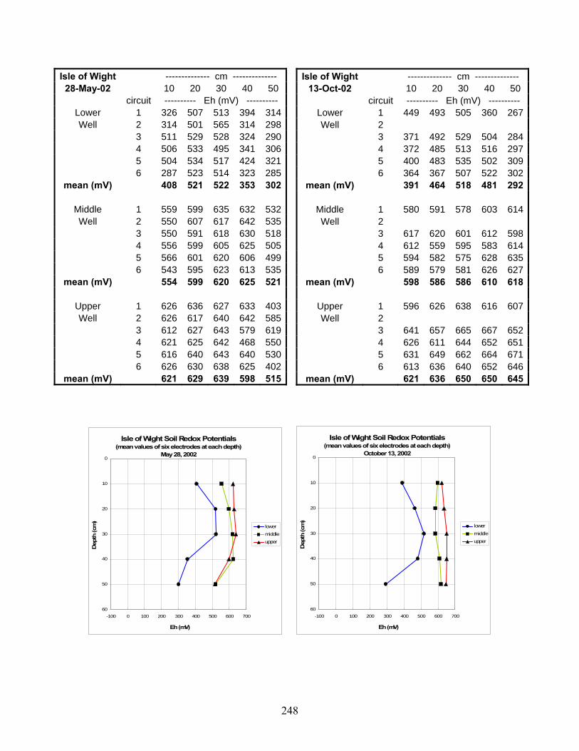
248
Isle of Wight -------------- cm -------------- 28-May-02 10 20 30 40 50
circuit ---------- Eh (mV) ---------- Lower 1 326 507 513 394 314Well 2 314 501 565 314 298
3 511 529 528 324 290 4 506 533 495 341 306 5 504 534 517 424 321 6 287 523 514 323 285
mean (mV) 408 521 522 353 302
Middle 1 559 599 635 632 532Well 2 550 607 617 642 535
3 550 591 618 630 518 4 556 599 605 625 505 5 566 601 620 606 499 6 543 595 623 613 535
mean (mV) 554 599 620 625 521
Upper 1 626 636 627 633 403Well 2 626 617 640 642 585
3 612 627 643 579 619 4 621 625 642 468 550 5 616 640 643 640 530 6 626 630 638 625 402
mean (mV) 621 629 639 598 515
Isle of Wight Soil Redox Potentials(mean values of six electrodes at each depth)
May 28, 20020
10
20
30
40
50
60-100 0 100 200 300 400 500 600 700
Eh (mV)
Dep
th (c
m)
lowermiddleupper
Isle of Wight Soil Redox Potentials(mean values of six electrodes at each depth)
October 13, 20020
10
20
30
40
50
60-100 0 100 200 300 400 500 600 700
Eh (mV)
Dep
th (c
m)
lowermiddleupper
Isle of Wight -------------- cm -------------- 13-Oct-02 10 20 30 40 50
circuit ---------- Eh (mV) ---------- Lower 1 449 493 505 360 267Well 2
3 371 492 529 504 284 4 372 485 513 516 297 5 400 483 535 502 309 6 364 367 507 522 302
mean (mV) 391 464 518 481 292
Middle 1 580 591 578 603 614Well 2
3 617 620 601 612 598 4 612 559 595 583 614 5 594 582 575 628 635 6 589 579 581 626 627
mean (mV) 598 586 586 610 618
Upper 1 596 626 638 616 607Well 2
3 641 657 665 667 652 4 626 611 644 652 651 5 631 649 662 664 671 6 613 636 640 652 646
mean (mV) 621 636 650 650 645

249
Isle of Wight -------------- cm -------------- 30-Nov-02 10 20 30 40 50
circuit ---------- Eh (mV) ---------- Lower 1 246 266 290 269 270Well 2 286 264 308 273 255
3 318 289 302 277 270 4 277 289 264 258 258 5 252 246 234 238 235 6 323 334 194 270 260
mean (mV) 284 281 265 264 258
Middle 1 593 327 293 302 285Well 2 593 275 285 293 274
3 475 301 290 308 312 4 536 293 255 311 299 5 436 235 253 264 252 6 553 310 295 328 310
mean (mV) 531 290 279 301 289
Upper 1 554 317 339 282 535Well 2 556 314 355 285 525
3 488 306 312 281 438 4 614 301 302 273 478 5 404 261 315 6 595 305 308 294 510
mean (mV) 535 301 322 283 497
Isle of Wight Soil Redox Potentials(mean values of six electrodes at each depth)
November 30, 20020
10
20
30
40
50
60-100 0 100 200 300 400 500 600 700
Eh (mV)
Dep
th (c
m)
lowermiddleupper
Isle of Wight Soil Redox Potentials(mean values of six electrodes at each depth)
January 6, 20030
10
20
30
40
50
60-100 0 100 200 300 400 500 600 700
Eh (mV)
Dep
th (c
m)
lowermiddleupper
Isle of Wight -------------- cm -------------- 6-Jan-03 10 20 30 40 50
circuit ---------- Eh (mV) ---------- Lower 1 202 286 298 280 264Well 2 285 300 308 297 282
3 147 253 306 281 257 4 292 330 300 282 264 5 262 259 303 239 208 6 244 249 249 245 244
mean (mV) 239 280 294 271 253
Middle 1 329 277 243 281 293Well 2 462 300 286 301 271
3 372 298 192 235 178 4 387 315 283 301 294 5 340 273 239 225 264 6 263 247 243 244 244
mean (mV) 359 285 248 265 257
Upper 1 349 275 306 260 465Well 2 319 244 281 279 479
3 301 273 205 261 546 4 377 293 281 262 508 5 329 289 235 187 495 6 260 244 242 241 294
mean (mV) 323 270 258 248 465

250
Isle of Wight -------------- cm -------------- 25-Jan-03 10 20 30 40 50
circuit ---------- Eh (mV) ---------- Lower 1 473 302 296 269 242Well 2 278 279 381 279 266
3 310 277 324 277 260 4 448 321 276 246 237 5 432 325 284 272 262 6 279 315 258 257 187
mean (mV) 370 303 303 267 242
Middle 1 540 257 241 207 228Well 2 531 344 235 225 226
3 531 355 280 248 234 4 581 281 224 219 212 5 602 578 277 277 256 6 570 542 286 231 216
mean (mV) 559 393 257 235 229
Upper 1 594 300 269 254 581Well 2 346 294 271 255 535
3 610 356 310 284 363 4 524 374 295 299 478 5 613 316 302 289 558 6 316 324 254 265 514
mean (mV) 501 327 284 274 505
Isle of WightSoil Redox Potentials(mean values of six electrodes at each depth)
January 25, 20030
10
20
30
40
50
60-100 0 100 200 300 400 500 600 700
Eh (mV)
Dep
th (c
m)
lowermiddleupper
Isle of Wight Soil Redox Potentials(mean values of six electrodes at each depth)
February 9, 20030
10
20
30
40
50
60-100 0 100 200 300 400 500 600 700
Eh (mV)
Dep
th (c
m)
lowermiddleupper
Isle of Wight -------------- cm -------------- 9-Feb-03 10 20 30 40 50
circuit ---------- Eh (mV) ---------- Lower 1 343 281 279 242 274Well 2 436 321 374 306 296
3 324 288 186 228 221 4 330 321 287 265 290 5 323 298 250 265 272 6
mean (mV) 351 302 275 261 271
Middle 1 457 276 169 221 235Well 2 496 305 249 252 262
3 539 307 237 236 253 4 567 455 244 260 237 5 544 412 272 184 249 6
mean (mV) 521 351 234 231 247
Upper 1 393 295 286 268 316Well 2 400 291 283 275 221
3 375 244 197 229 200 4 427 267 256 252 205 5 417 334 273 252 224 6
mean (mV) 402 286 259 255 233

251
Isle of Wight -------------- cm -------------- 1-Mar-03 10 20 30 40 50
circuit ---------- Eh (mV) ---------- Lower 1 292 294 284 258 244Well 2 297 283 269 261 247
3 338 335 350 326 298 4 295 283 291 581 327 5 298 276 406 456 271 6 316 329 402 359 436
mean (mV) 306 300 334 374 304
Middle 1 361 396 248 227 237Well 2 370 437 257 224 224
3 436 466 292 273 248 4 527 520 265 251 226 5 567 491 286 250 214 6 542 479 264 244 225
mean (mV) 467 465 269 245 229
Upper 1 349 289 428 295 261Well 2 304 268 249 231 216
3 360 314 293 286 275 4 321 269 279 229 198 5 274 218 246 243 274 6 298 283 220 230 209
mean (mV) 318 274 286 252 239
Isle of Wight Soil Redox Potentials(mean values of six electrodes at each depth)
March 1, 20030
10
20
30
40
50
60-100 0 100 200 300 400 500 600 700
Eh (mV)
Dep
th (c
m)
lowermiddleupper
Isle of Wight Soil Redox Potentials(mean values of six electrodes at each depth)
March 24, 20030
10
20
30
40
50
60-100 0 100 200 300 400 500 600 700
Eh (mV)
Dep
th (c
m)
lowermiddleupper
Isle of Wight -------------- cm -------------- 24-Mar-03 10 20 30 40 50
circuit ---------- Eh (mV) ---------- Lower 1 406 306 339 258 244Well 2
3 277 218 249 236 212 4 269 218 224 211 217 5 293 288 233 235 199 6 315 311 272 244 239
mean (mV) 312 268 263 237 222
Middle 1 459 320 219 244 252Well 2
3 472 339 316 294 226 4 311 301 259 241 138 5 403 331 306 280 170 6 444 316 297 289 183
mean (mV) 418 321 279 270 194
Upper 1 318 239 231 247 476Well 2
3 303 255 290 292 432 4 336 279 269 232 459 5 291 257 253 231 525 6 296 244 277 234 400
mean (mV) 309 255 264 247 458

252
Isle of Wight -------------- cm -------------- 4-Apr-03 10 20 30 40 50
circuit ---------- Eh (mV) ---------- Lower 1 314 232 271 205 194Well 2
3 285 289 260 237 240 4 180 266 290 256 257 5 322 332 344 312 303 6 277 209 223 217 216
mean (mV) 276 266 278 245 242
Middle 1 359 294 61 185 182Well 2
3 386 273 194 211 198 4 331 320 296 257 143 5 321 316 256 268 251 6 385 320 207 218 109
mean (mV) 356 305 203 228 177
Upper 1 173 142 204 211 190Well 2
3 269 225 258 235 225 4 299 207 246 205 220 5 201 203 223 187 191 6 292 225 241 239 209
mean (mV) 247 200 234 215 207
Isle of Wight Soil Redox Potentials(mean values of six electrodes at each depth)
April 4, 20030
10
20
30
40
50
60-100 0 100 200 300 400 500 600 700
Eh (mV)
Dep
th (c
m)
lowermiddleupper
Isle of Wight Soil Redox Potentials(mean values of six electrodes at each depth)
April 16, 20030
10
20
30
40
50
60-100 0 100 200 300 400 500 600 700
Eh (mV)
Dep
th (c
m)
lowermiddleupper
Isle of Wight -------------- cm -------------- 16-Apr-03 10 20 30 40 50
circuit ---------- Eh (mV) ---------- Lower 1 114 213 251 234 221Well 2 27 198 245 232 214
3 258 303 311 281 267 4 50 238 271 236 226 5 2 277 253 263 253 6
mean (mV) 90 246 266 249 236
Middle 1 394 312 286 271 246Well 2 416 329 267 275 228
3 397 311 259 258 263 4 654 326 257 262 225 5 380 344 294 255 239 6
mean (mV) 448 324 273 264 240
Upper 1 315 244 244 52 566Well 2 300 317 281 181 535
3 329 295 244 243 544 4 349 298 282 246 582 5 360 279 265 250 448 6
mean (mV) 331 287 263 194 535

253
Isle of Wight -------------- cm -------------- 2-May-03 10 20 30 40 50
circuit ---------- Eh (mV) ---------- Lower 1 258 265 255 400 420Well 2 61 262 270 279 312
3 139 199 192 261 247 4 233 217 154 249 468 5 274 357 276 392 297 6
mean (mV) 193 260 229 316 349
Middle 1 339 330 244 231 246Well 2 332 314 64 209 215
3 282 259 203 192 183 4 300 305 172 194 182 5 415 278 194 166 168 6
mean (mV) 334 297 175 198 199
Upper 1 289 242 255 225 194Well 2 290 247 269 228 209
3 272 213 244 223 205 4 244 216 233 199 178 5 324 279 248 216 200 6
mean (mV) 284 239 250 218 197
Isle of Wight Soil Redox Potentials(mean values of six electrodes at each depth)
May 2, 20030
10
20
30
40
50
60-100 0 100 200 300 400 500 600 700
Eh (mV)
Dep
th (c
m)
lowermiddleupper
Isle of Wight Soil Redox Potentials(mean values of six electrodes at each depth)
May 19, 20030
10
20
30
40
50
60-100 0 100 200 300 400 500 600 700
Eh (mV)
Dep
th (c
m)
lowermiddleupper
Isle of Wight -------------- cm -------------- 19-May-03 10 20 30 40 50
circuit ---------- Eh (mV) ---------- Lower 1 137 198 209 205 197Well 2 195 254 236 239 227
3 167 248 233 221 221 4 181 257 258 244 244 5 237 251 251 253 255 6
mean (mV) 183 242 237 232 229
Middle 1 244 239 205 189 206Well 2 217 233 213 232 207
3 256 250 220 202 203 4 272 254 186 203 195 5 259 267 192 205 188 6
mean (mV) 250 249 203 206 200
Upper 1 256 276 237 219 165Well 2 306 283 243 215 248
3 276 281 230 227 240 4 276 273 198 216 233 5 271 272 233 213 203 6
mean (mV) 277 277 228 218 218

254
Isle of Wight -------------- cm -------------- 1-Jun-03 10 20 30 40 50
circuit ---------- Eh (mV) ---------- Lower 1 141 150 205 210 354Well 2 123 166 184 170 449
3 91 163 180 169 208 4 242 223 254 216 224 5 226 244 253 234 223 6 201 282 288 286 263
mean (mV) 171 205 227 214 287
Middle 1 243 259 177 209 188Well 2 215 241 202 186 165
3 196 227 197 178 188 4 205 234 170 236 255 5 250 273 207 205 201 6 281 273 289 265 252
mean (mV) 232 251 207 213 208
Upper 1 267 244 244 188 201Well 2 221 190 194 170 172
3 260 159 212 206 192 4 277 262 277 239 231 5 307 264 293 251 224 6 302 286 300 243 222
mean (mV) 272 234 253 216 207
Isle of Wight Soil Redox Potentials(mean values of six electrodes at each depth)
June 1, 20030
10
20
30
40
50
60-100 0 100 200 300 400 500 600 700
Eh (mV)
Dep
th (c
m)
lowermiddleupper
Isle of Wight Soil Redox Potentials(mean values of six electrodes at each depth)
June 18, 20030
10
20
30
40
50
60-100 0 100 200 300 400 500 600 700
Eh (mV)
Dep
th (c
m)
lowermiddleupper
Isle of Wight -------------- cm -------------- 18-Jun-03 10 20 30 40 50
circuit ---------- Eh (mV) ---------- Lower 1 Well 2 272 331 360 506 556
3 190 289 303 397 535 4 53 49 269 294 515 5 271 266 387 375 507 6 374 363 418 423 511
mean (mV) 232 260 347 399 525
Middle 1 Well 2 367 318 229 273 612
3 491 536 261 285 273 4 297 351 200 224 243 5 251 230 237 249 269 6 263 322 289 299 316
mean (mV) 334 351 243 266 343
Upper 1 Well 2 194 265 281 188 243
3 154 235 241 205 222 4 176 247 271 224 245 5 327 286 325 242 244 6 279 321 322 309 288
mean (mV) 226 271 288 234 248

255
Isle of Wight -------------- cm -------------- 17-Jul-03 10 20 30 40 50
circuit ---------- Eh (mV) ---------- Lower 1 Well 2 403 502 242 239 256
3 414 539 195 227 258 4 473 521 404 355 332 5 391 525 269 287 382 6 351 500 420 398 343
mean (mV) 406 517 306 301 314
Middle 1 Well 2 517 573 580 319 261
3 503 571 601 301 610 4 549 571 564 349 601 5 567 582 543 458 623 6 534 641 564 300 349
mean (mV) 534 588 570 345 489
Upper 1 Well 2 567 603 620 523 326
3 618 626 632 642 295 4 604 611 606 616 336 5 610 611 635 387 310 6 579 589 599 595 415
mean (mV) 596 608 618 553 336
Isle of Wight Soil Redox Potentials(mean values of six electrodes at each depth)
July 17, 20030
10
20
30
40
50
60-100 0 100 200 300 400 500 600 700
Eh (mV)
Dep
th (c
m)
lowermiddleupper
Isle of Wight Soil Redox Potentials(mean values of six electrodes at each depth)
August 19, 20030
10
20
30
40
50
60-100 0 100 200 300 400 500 600 700
Eh (mV)
Dep
th (c
m)
lowermiddleupper
Isle of Wight -------------- cm -------------- 19-Aug-03 10 20 30 40 50
circuit ---------- Eh (mV) ---------- Lower 1 Well 2 297 335 365 336 295
3 343 349 306 253 288 4 509 299 285 283 308 5 371 286 302 301 265 6 346 335 331 364 361
mean (mV) 373 321 318 307 303
Middle 1 Well 2 573 585 552 612 345
3 554 589 494 617 402 4 580 584 584 638 350 5 569 572 487 607 388 6 559 575 448 585 399
mean (mV) 567 581 513 612 377
Upper 1 Well 2 530 623 606 583 252
3 635 631 614 542 299 4 614 614 633 648 325 5 605 611 618 599 311 6 615 641 651 600 287
mean (mV) 600 624 624 594 295
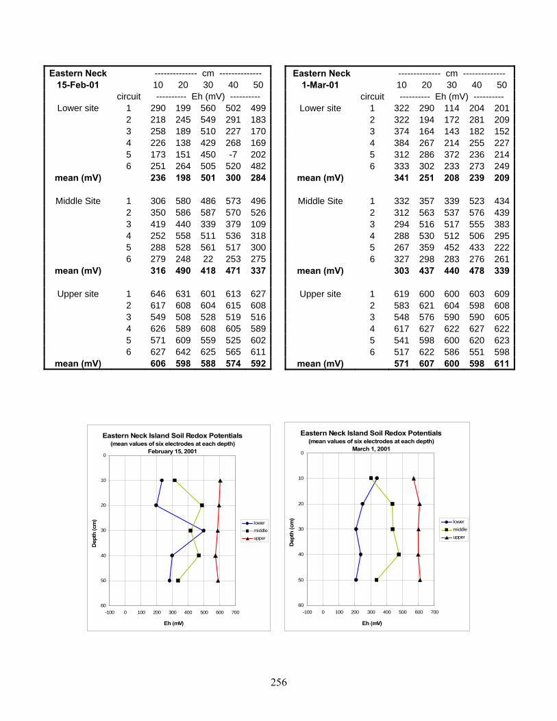
256
Eastern Neck -------------- cm -------------- 15-Feb-01 10 20 30 40 50
circuit ---------- Eh (mV) ---------- Lower site 1 290 199 560 502 499
2 218 245 549 291 183 3 258 189 510 227 170 4 226 138 429 268 169 5 173 151 450 -7 202 6 251 264 505 520 482
mean (mV) 236 198 501 300 284
Middle Site 1 306 580 486 573 496 2 350 586 587 570 526 3 419 440 339 379 109 4 252 558 511 536 318 5 288 528 561 517 300 6 279 248 22 253 275
mean (mV) 316 490 418 471 337
Upper site 1 646 631 601 613 627 2 617 608 604 615 608 3 549 508 528 519 516 4 626 589 608 605 589 5 571 609 559 525 602 6 627 642 625 565 611
mean (mV) 606 598 588 574 592
Eastern Neck Island Soil Redox Potentials(mean values of six electrodes at each depth)
February 15, 20010
10
20
30
40
50
60-100 0 100 200 300 400 500 600 700
Eh (mV)
Dep
th (c
m)
lowermiddleupper
Eastern Neck Island Soil Redox Potentials(mean values of six electrodes at each depth)
March 1, 20010
10
20
30
40
50
60-100 0 100 200 300 400 500 600 700
Eh (mV)
Dep
th (c
m)
lowermiddleupper
Eastern Neck -------------- cm -------------- 1-Mar-01 10 20 30 40 50
circuit ---------- Eh (mV) ---------- Lower site 1 322 290 114 204 201
2 322 194 172 281 209 3 374 164 143 182 152 4 384 267 214 255 227 5 312 286 372 236 214 6 333 302 233 273 249
mean (mV) 341 251 208 239 209
Middle Site 1 332 357 339 523 434 2 312 563 537 576 439 3 294 516 517 555 383 4 288 530 512 506 295 5 267 359 452 433 222 6 327 298 283 276 261
mean (mV) 303 437 440 478 339
Upper site 1 619 600 600 603 609 2 583 621 604 598 608 3 548 576 590 590 605 4 617 627 622 627 622 5 541 598 600 620 623 6 517 622 586 551 598
mean (mV) 571 607 600 598 611

257
Eastern Neck -------------- cm -------------- Mar 18,2001 10 20 30 40 50
circuit ---------- Eh (mV) ---------- Lower site 1 201 257 280 222 229
2 274 254 215 -141 142 3 231 162 130 141 129 4 168 269 300 294 267 5 275 244 160 94 134 6 274 252 177 301 190
mean (mV) 237 240 210 152 182
Middle Site 1 310 293 200 156 174 2 214 268 366 264 197 3 200 120 116 82 87 4 318 297 224 211 178 5 255 198 149 64 129 6 350 303 158 361 220
mean (mV) 275 247 202 190 164
Upper site 1 641 618 555 574 599 2 654 610 622 545 594 3 630 611 600 598 608 4 535 538 538 579 552 5 497 609 559 575 574 6 640 609 605 602 570
mean (mV) 600 599 580 579 583
Eastern Neck Island Soil Redox Potentials(mean values of six electrodes at each depth)
March 18, 20010
10
20
30
40
50
60-100 0 100 200 300 400 500 600 700
Eh (mV)
Dep
th (c
m)
lowermiddleupper
Eastern Neck Island Soil Redox Potentials(mean values of six electrodes at each depth)
April 5, 20010
10
20
30
40
50
60-100 0 100 200 300 400 500 600 700
Eh (mV)
Dep
th (c
m)
lowermiddleupper
Eastern Neck -------------- cm -------------- 5-Apr-01 10 20 30 40 50
circuit ---------- Eh (mV) ---------- Lower site 1 143 242 283 263 218
2 326 285 296 227 213 3 314 236 306 227 217 4 332 235 222 215 171 5 295 189 158 191 190 6
mean (mV) 282 237 253 225 202
Middle Site 1 267 224 251 265 254 2 272 197 245 257 222 3 257 204 251 100 88 4 310 227 215 156 208 5 164 211 236 225 73 6
mean (mV) 254 213 240 201 169
Upper site 1 614 578 487 572 597 2 626 522 544 555 606 3 585 567 516 547 583 4 600 589 548 484 553 5 548 466 541 380 520 6
mean (mV) 595 544 527 508 572

258
Eastern Neck -------------- cm -------------- 19-Apr-01 10 20 30 40 50
circuit ---------- Eh (mV) ---------- Lower site 1 166 251 262 211 207
2 128 228 237 251 244 3 32 33 65 73 73 4 257 261 50 163 204 5 158 212 76 180 206 6 -39 153 179 202 224
mean (mV) 117 190 145 180 193
Middle Site 1 143 251 264 215 238 2 302 230 242 227 261 3 110 151 117 74 15 4 123 255 263 245 214 5 304 248 249 283 235 6 220 276 214 219 216
mean (mV) 200 235 225 211 197
Upper site 1 550 373 265 485 532 2 492 258 295 502 535 3 546 282 66 154 492 4 569 313 336 427 570 5 547 309 304 512 473 6 478 262 162 472 529
mean (mV) 530 300 238 425 522
Eastern Neck Island Soil Redox Potentials(mean values of six electrodes at each depth)
April 19, 20010
10
20
30
40
50
60-100 0 100 200 300 400 500 600 700
Eh (mV)
Dep
th (c
m)
lowermiddleupper
Eastern Neck Island Soil Redox Potentials(mean values of six electrodes at each depth)
May 1, 20010
10
20
30
40
50
60-100 0 100 200 300 400 500 600 700
Eh (mV)
Dep
th (c
m)
lowermiddleupper
Eastern Neck -------------- cm -------------- 1-May-01 10 20 30 40 50
circuit ---------- Eh (mV) ---------- Lower site 1 257 363 349 314 338
2 349 290 330 353 285 3 242 370 309 285 242 4 279 371 301 260 225 5 287 309 306 240 290 6 325 272 284 302 348
mean (mV) 290 329 313 292 288
Middle Site 1 174 393 326 335 332 2 396 350 314 314 297 3 141 480 314 109 200 4 188 276 234 204 204 5 126 273 320 306 252 6 383 268 302 336 229
mean (mV) 235 340 302 267 252
Upper site 1 565 635 486 536 518 2 587 640 478 281 286 3 561 629 615 139 229 4 503 608 478 129 310 5 570 647 559 495 137 6 629 660 631 505 194
mean (mV) 569 637 541 348 279

259
Eastern Neck -------------- cm -------------- 16-May-01 10 20 30 40 50
circuit ---------- Eh (mV) ---------- Lower site 1 576 610 626 626 628
2 589 603 632 626 632 3 575 578 618 624 610 4 551 569 623 617 604 5 546 575 627 594 593 6 564 599 612 618 605
mean (mV) 567 589 623 618 612
Middle Site 1 601 639 638 604 631 2 599 630 608 610 616 3 580 624 638 627 600 4 562 612 604 606 574 5 549 616 600 619 622 6 600 630 602 620 633
mean (mV) 582 625 615 614 613
Upper site 1 633 664 678 678 679 2 645 627 657 661 668 3 610 651 656 644 664 4 620 649 638 646 609 5 679 650 639 651 656 6 636 620 608 632 655
mean (mV) 637 644 646 652 655
Eastern Neck Island Soil Redox Potentials(mean values of six electrodes at each depth)
May 16, 20010
10
20
30
40
50
60-100 0 100 200 300 400 500 600 700
Eh (mV)
Dep
th (c
m)
lowermiddleupper
Eastern Neck Island Soil Redox Potentials(mean values of six electrodes at each depth)
May 28, 20010
10
20
30
40
50
60-100 0 100 200 300 400 500 600 700
Eh (mV)
Dep
th (c
m)
lowermiddleupper
Eastern Neck -------------- cm -------------- 28-May-01 10 20 30 40 50
circuit ---------- Eh (mV) ---------- Lower site 1 334 608 621 638 549
2 327 290 485 578 408 3 346 544 598 605 554 4 353 566 568 584 574 5 321 569 566 601 559 6 292 426 494 378 358
mean (mV) 329 501 555 564 500
Middle Site 1 380 609 619 610 557 2 465 602 616 603 581 3 532 593 630 620 645 4 248 598 586 602 605 5 381 601 616 617 652 6 270 468 492 481 510
mean (mV) 379 579 593 589 592
Upper site 1 441 623 656 658 676 2 559 648 595 642 663 3 598 634 671 657 661 4 501 633 635 650 662 5 612 663 662 643 658 6 363 381 496 525 534
mean (mV) 512 597 619 629 642

260
Eastern Neck -------------- cm -------------- 11-Jun-01 10 20 30 40 50
circuit ---------- Eh (mV) ---------- Lower site 1 342 342 263 302 326
2 297 265 255 275 267 3 272 350 345 318 310 4 300 244 229 248 180 5 306 305 295 277 298 6 261 301 278 278 295
mean (mV) 296 301 278 283 279
Middle Site 1 389 363 570 568 561 2 278 310 567 552 556 3 365 329 378 341 473 4 315 295 307 280 148 5 373 365 326 395 332 6 262 350 494 492 276
mean (mV) 330 335 440 438 391
Upper site 1 595 643 637 606 675 2 639 648 623 575 634 3 642 632 639 646 635 4 623 603 609 617 639 5 633 655 596 655 655 6 620 636 616 642 658
mean (mV) 625 636 620 624 649
Eastern Neck Island Soil Redox Potentials(mean values of six electrodes at each depth)
June 11, 20010
10
20
30
40
50
60-100 0 100 200 300 400 500 600 700
Eh (mV)
Dep
th (c
m)
lowermiddleupper
Eastern Neck Island Soil Redox Potentials(mean values of six electrodes at each depth)
June 24, 20010
10
20
30
40
50
60-100 0 100 200 300 400 500 600 700
Eh (mV)
Dep
th (c
m)
lowermiddleupper
Eastern Neck -------------- cm -------------- 24-Jun-01 10 20 30 40 50
circuit ---------- Eh (mV) ---------- Lower site 1 332 478 322 286 246
2 314 545 570 395 360 3 311 575 551 431 382 4 305 550 391 296 295 5 545 574 394 367 273 6 517 580 442 415 342
mean (mV) 387 550 445 365 316
Middle Site 1 472 528 567 515 360 2 262 548 568 398 218 3 321 513 535 340 252 4 340 559 315 314 261 5 390 561 518 282 283 6 458 604 585 411 271
mean (mV) 374 552 515 377 274
Upper site 1 626 603 599 614 611 2 621 629 653 619 588 3 609 640 282 641 622 4 638 646 640 643 624 5 623 654 642 632 635 6 647 664 647 642 642
mean (mV) 627 639 577 632 620

261
Eastern Neck -------------- cm -------------- 9-Jul-01 10 20 30 40 50
circuit ---------- Eh (mV) ---------- Lower site 1 570 569 586 604 606
2 557 615 646 630 634 3 559 608 619 623 614 4 440 595 542 485 573 5 591 603 645 591 625 6 555 615 617 623 632
mean (mV) 545 601 609 593 614
Middle Site 1 603 621 642 615 642 2 564 623 642 651 655 3 631 635 651 583 644 4 621 618 632 638 595 5 619 636 648 651 634 6 629 630 647 622 641
mean (mV) 611 627 644 627 635
Upper site 1 660 662 673 678 699 2 680 613 664 659 682 3 681 636 669 683 684 4 658 637 659 674 682 5 671 661 678 680 698 6 683 664 687 692 654
mean (mV) 672 646 672 678 683
Eastern Neck Island Soil Redox Potentials(mean values of six electrodes at each depth)
July 9, 20010
10
20
30
40
50
60-100 0 100 200 300 400 500 600 700
Eh (mV)
Dep
th (c
m)
lowermiddleupper
Eastern Neck Island Soil Redox Potentials(mean values of six electrodes at each depth)
July 20, 20010
10
20
30
40
50
60-100 0 100 200 300 400 500 600 700
Eh (mV)
Dep
th (c
m)
lowermiddleupper
Eastern Neck -------------- cm -------------- 20-Jul-01 10 20 30 40 50
circuit ---------- Eh (mV) ---------- Lower site 1 594 626 639 620 642
2 597 257 663 642 666 3 596 588 626 620 645 4 591 561 620 616 628 5 616 632 643 634 646 6 601 630 593 653 649
mean (mV) 599 549 631 631 646
Middle Site 1 612 651 660 634 663 2 621 647 664 657 669 3 627 637 659 642 653 4 628 642 638 621 642 5 621 631 618 652 651 6 621 618 655 658 660
mean (mV) 622 638 649 644 656
Upper site 1 648 656 669 685 2 653 673 679 662 3 670 659 677 679 4 636 655 660 668 5 634 661 678 696 6 622 642 667 681
mean (mV) 644 658 672 679

262
Eastern Neck -------------- cm -------------- 12-Dec-01 10 20 30 40 50
circuit ---------- Eh (mV) ---------- Lower site 1 641 627 631 636 642
2 642 640 636 636 656 3 641 642 638 614 636 4 609 632 642 642 664 5 610 642 635 643 654 6 602 621 585 603
mean (mV) 624 634 628 629 650
Middle Site 1 627 638 642 2 644 633 3 644 581 625 4 556 575 5 6 644 551 635
mean (mV) 627 604 639
Upper site 1 2 3 4 5 6
mean (mV)
Eastern Neck Island Soil Redox Potentials(mean values of six electrodes at each depth)
December 12, 20010
10
20
30
40
50
60-100 0 100 200 300 400 500 600 700
Eh (mV)
Dep
th (c
m)
lowermiddleupper
Eastern Neck Island Soil Redox Potentials(mean values of six electrodes at each depth)
January 10, 20020
10
20
30
40
50
60-100 0 100 200 300 400 500 600 700
Eh (mV)
Dep
th (c
m)
lowermiddleupper
Eastern Neck -------------- cm -------------- 10-Jan-02 10 20 30 40 50
circuit ---------- Eh (mV) ---------- Lower site 1 603 576 586 603 603
2 606 574 593 610 595 3 611 591 615 622 607 4 615 600 608 624 619 5 605 604 602 621 616 6 609 623 612 625 623
mean (mV) 608 595 603 618 611
Middle Site 1 618 635 615 616 623 2 612 644 607 631 630 3 632 646 613 629 632 4 638 644 616 625 620 5 615 640 609 620 616 6 604 644 614 605 619
mean (mV) 620 642 612 621 623
Upper site 1 645 655 653 642 2 655 665 664 644 3 626 661 660 650 4 616 648 654 635 5 615 650 657 641 6 621 657 656 650
mean (mV) 630 656 657 644

263
Eastern Neck -------------- cm -------------- 2-Feb-02 10 20 30 40 50
circuit ---------- Eh (mV) ---------- Lower site 1 570 626 623 607 632
2 620 644 655 633 644 3 544 585 608 592 583 4 610 619 638 644 648 5 611 632 588 619 638 6 561 610 602 625 621
mean (mV) 586 619 619 620 628
Middle Site 1 638 644 605 590 605 2 643 624 635 622 627 3 598 610 594 579 581 4 651 670 659 612 630 5 632 658 644 622 624 6 566 652 600 575 620
mean (mV) 621 643 623 600 615
Upper site 1 624 640 639 644 645 2 643 664 671 651 650 3 588 659 665 664 655 4 659 672 676 668 658 5 648 663 676 679 669 6 657 640 669 665 663
mean (mV) 637 656 666 662 657
Eastern Neck Island Soil Redox Potentials(mean values of six electrodes at each depth)
February 2, 20020
10
20
30
40
50
60-100 0 100 200 300 400 500 600 700
Eh (mV)
Dep
th (c
m)
lowermiddleupper
Eastern Neck Island Soil Redox Potentials(mean values of six electrodes at each depth)
February 17, 20020
10
20
30
40
50
60-100 0 100 200 300 400 500 600 700
Eh (mV)
Dep
th (c
m)
lowermiddleupper
Eastern Neck -------------- cm -------------- 17-Feb-02 10 20 30 40 50
circuit ---------- Eh (mV) ---------- Lower site 1 617 639 642 641 624
2 601 626 634 640 631 3 605 626 638 635 621 4 610 655 648 648 639 5 601 632 626 606 617 6 613 631 599 595 598
mean (mV) 608 635 631 628 622
Middle Site 1 619 646 637 622 608 2 629 621 636 627 626 3 622 621 611 601 620 4 602 631 624 616 617 5 640 516 551 527 518 6 563 618 631 633 611
mean (mV) 613 609 615 604 600
Upper site 1 652 676 667 666 662 2 633 659 654 654 651 3 638 659 669 673 657 4 637 663 673 667 663 5 646 671 651 663 656 6 641 653 656 670 661
mean (mV) 641 664 662 666 658

264
Eastern Neck -------------- cm -------------- 3-Mar-02 10 20 30 40 50
circuit ---------- Eh (mV) ---------- Lower site 1 562 623 650 601 609
2 558 563 628 575 558 3 612 629 628 603 598 4 592 614 625 589 609 5 603 608 613 583 609 6 624 619 620 585 566
mean (mV) 592 609 627 589 592
Middle Site 1 640 646 646 626 621 2 625 645 643 623 615 3 620 652 642 626 634 4 634 637 633 629 625 5 621 651 646 622 607 6 624 646 640 621 621
mean (mV) 627 646 642 625 621
Upper site 1 652 669 672 670 669 2 658 677 674 664 661 3 651 668 677 679 676 4 659 672 675 666 654 5 661 669 665 634 667 6 635 662 675 673 675
mean (mV) 653 670 673 664 667
Eastern Neck Island Soil Redox Potentials(mean values of six electrodes at each depth)
March 3, 20020
10
20
30
40
50
60-100 0 100 200 300 400 500 600 700
Eh (mV)
Dep
th (c
m)
lowermiddleupper
Eastern Neck Island Soil Redox Potentials(mean values of six electrodes at each depth)
March 29, 20020
10
20
30
40
50
60-100 0 100 200 300 400 500 600 700
Eh (mV)
Dep
th (c
m)
lowermiddleupper
Eastern Neck -------------- cm -------------- 29-Mar-02 10 20 30 40 50
circuit ---------- Eh (mV) ---------- Lower site 1 538 589 546 585 561
2 535 583 635 584 573 3 566 558 635 590 572 4 558 609 620 611 557 5 6
mean (mV) 549 585 609 593 566
Middle Site 1 590 624 646 620 611 2 603 634 654 632 623 3 618 631 648 627 625 4 590 633 642 623 613 5 6
mean (mV) 600 631 648 626 618
Upper site 1 611 667 676 668 658 2 650 667 664 661 642 3 635 672 674 679 653 4 631 664 672 673 650 5 6
mean (mV) 632 668 672 670 651
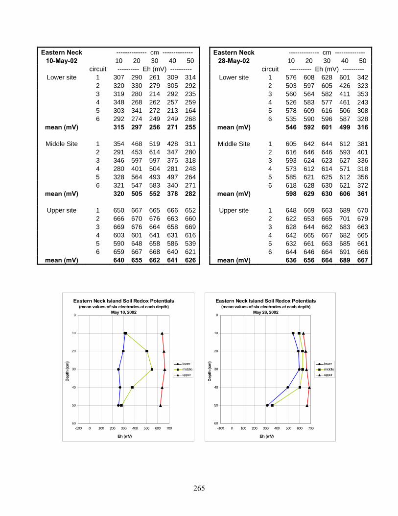
265
Eastern Neck -------------- cm -------------- 10-May-02 10 20 30 40 50
circuit ---------- Eh (mV) ---------- Lower site 1 307 290 261 309 314
2 320 330 279 305 292 3 319 280 214 292 235 4 348 268 262 257 259 5 303 341 272 213 164 6 292 274 249 249 268
mean (mV) 315 297 256 271 255
Middle Site 1 354 468 519 428 311 2 291 453 614 347 280 3 346 597 597 375 318 4 280 401 504 281 248 5 328 564 493 497 264 6 321 547 583 340 271
mean (mV) 320 505 552 378 282
Upper site 1 650 667 665 666 652 2 666 670 676 663 660 3 669 676 664 658 669 4 603 601 641 631 616 5 590 648 658 586 539 6 659 667 668 640 621
mean (mV) 640 655 662 641 626
Eastern Neck Island Soil Redox Potentials(mean values of six electrodes at each depth)
May 10, 20020
10
20
30
40
50
60-100 0 100 200 300 400 500 600 700
Eh (mV)
Dep
th (c
m)
lowermiddleupper
Eastern Neck Island Soil Redox Potentials(mean values of six electrodes at each depth)
May 28, 20020
10
20
30
40
50
60-100 0 100 200 300 400 500 600 700
Eh (mV)
Dep
th (c
m)
lowermiddleupper
Eastern Neck -------------- cm -------------- 28-May-02 10 20 30 40 50
circuit ---------- Eh (mV) ---------- Lower site 1 576 608 628 601 342
2 503 597 605 426 323 3 560 564 582 411 353 4 526 583 577 461 243 5 578 609 616 506 308 6 535 590 596 587 328
mean (mV) 546 592 601 499 316
Middle Site 1 605 642 644 612 381 2 616 646 646 593 401 3 593 624 623 627 336 4 573 612 614 571 318 5 585 621 625 612 356 6 618 628 630 621 372
mean (mV) 598 629 630 606 361
Upper site 1 648 669 663 689 670 2 622 653 665 701 679 3 628 644 662 683 663 4 642 665 667 682 665 5 632 661 663 685 661 6 644 646 664 691 666
mean (mV) 636 656 664 689 667

266
Eastern Neck -------------- cm -------------- 15-Oct-02 10 20 30 40 50
circuit ---------- Eh (mV) ---------- Lower site 1 579 619 648 624 628
2 577 633 646 604 630 3 606 625 658 617 629 4 596 644 653 631 624 5 621 642 651 621 632 6 595 642 642 625 619
mean (mV) 596 634 650 620 627
Middle Site 1 623 668 641 652 617 2 628 665 670 647 612 3 646 672 675 624 610 4 5 636 673 662 646 641 6 604 640 634 641 631
mean (mV) 627 664 656 642 622
Upper site 1 622 635 654 638 645 2 624 666 679 660 655 3 610 654 663 633 653 4 5 654 661 671 658 634 6 652 667 670 652 649
mean (mV) 632 657 667 648 647
Eastern Neck Island Soil Redox Potentials(mean values of six electrodes at each depth)
October 15, 20020
10
20
30
40
50
60-100 0 100 200 300 400 500 600 700
Eh (mV)
Dep
th (c
m)
lowermiddleupper
Eastern Neck Island Soil Redox Potentials(mean values of six electrodes at each depth)
December 1, 20020
10
20
30
40
50
60-100 0 100 200 300 400 500 600 700
Eh (mV)
Dep
th (c
m)
lowermiddleupper
Eastern Neck -------------- cm -------------- 1-Dec-02 10 20 30 40 50
circuit ---------- Eh (mV) ---------- Lower site 1 320 288 224 281 283
2 329 192 249 253 256 3 259 234 254 215 224 4 298 287 234 241 274 5 245 154 206 182 415 6 276 266 258 271 315
mean (mV) 288 237 238 241 295
Middle Site 1 288 289 335 538 576 2 281 262 226 550 568 3 248 233 231 373 353 4 351 299 475 523 530 5 253 241 519 466 499 6 355 357 583 607 616
mean (mV) 296 280 395 510 524
Upper site 1 659 675 595 581 347 2 548 652 604 597 587 3 540 542 409 422 329 4 661 673 611 623 557 5 604 618 502 513 417 6 668 669 495 337 379
mean (mV) 613 638 536 512 436

267
Eastern Neck -------------- cm -------------- 12-Jan-03 10 20 30 40 50
circuit ---------- Eh (mV) ---------- Lower site 1 214 241 -16 156 228
2 198 239 175 209 232 3 242 214 162 180 239 4 251 255 168 182 245 5 285 94 102 230 286 6
mean (mV) 238 209 118 191 246
Middle Site 1 219 195 193 170 218 2 253 209 232 220 241 3 231 183 214 55 149 4 178 231 199 172 232 5 277 245 243 90 262 6
mean (mV) 232 213 216 141 220
Upper site 1 589 562 252 201 195 2 584 478 302 259 208 3 585 449 277 243 205 4 586 592 289 242 228 5 563 430 282 246 231 6
mean (mV) 581 502 280 238 213
Eastern Neck Island Soil Redox Potentials(mean values of six electrodes at each depth)
January 12, 20030
10
20
30
40
50
60-100 0 100 200 300 400 500 600 700
Eh (mV)
Dep
th (c
m)
lowermiddleupper
Eastern Neck Island Soil Redox Potentials(mean values of six electrodes at each depth)
February 8, 20030
10
20
30
40
50
60-100 0 100 200 300 400 500 600 700
Eh (mV)
Dep
th (c
m)
lowermiddleupper
Eastern Neck -------------- cm -------------- 8-Feb-03 10 20 30 40 50
circuit ---------- Eh (mV) ---------- Lower site 1 508 402 372 350 331
2 465 340 368 284 299 3 422 326 174 285 300 4 590 537 503 504 512 5 186 266 247 245 255 6 324 91 5 178 209
mean (mV) 416 327 278 308 318
Middle Site 1 370 287 254 249 226 2 367 342 344 320 292 3 429 389 344 326 296 4 338 341 312 295 269 5 346 344 333 290 257 6
mean (mV) 370 341 317 296 268
Upper site 1 654 655 617 361 277 2 634 642 612 361 82 3 619 626 471 335 199 4 606 634 603 393 222 5 642 634 630 -7 73 6
mean (mV) 631 638 587 289 171

268
Eastern Neck -------------- cm -------------- 2-Mar-03 10 20 30 40 50
circuit ---------- Eh (mV) ---------- Lower site 1 223 245 255 263 257
2 235 243 245 243 232 3 220 247 263 246 244 4 208 229 250 249 231 5 6
mean (mV) 222 241 253 250 241
Middle Site 1 291 231 245 244 245 2 151 37 224 239 233 3 332 261 259 247 245 4 285 194 223 248 243 5 6
mean (mV) 265 181 238 245 242
Upper site 1 615 658 494 225 245 2 547 637 332 229 219 3 608 655 539 248 225 4 593 642 431 247 222 5 6
mean (mV) 591 648 449 237 228
Eastern Neck Island Soil Redox Potentials(mean values of six electrodes at each depth)
March 2, 20030
10
20
30
40
50
60-100 0 100 200 300 400 500 600 700
Eh (mV)
Dep
th (c
m)
lowermiddleupper
Eastern Neck Island Soil Redox Potentials(mean values of six electrodes at each depth)
March 25, 20030
10
20
30
40
50
60-100 0 100 200 300 400 500 600 700
Eh (mV)
Dep
th (c
m)
lowermiddleupper
Eastern Neck -------------- cm -------------- 25-Mar-03 10 20 30 40 50
circuit ---------- Eh (mV) ---------- Lower site 1 254 232 265 233 251
2 3 135 197 126 231 249 4 184 108 204 224 224 5 169 167 250 224 256 6 173 89 281 239 281
mean (mV) 183 159 225 230 252
Middle Site 1 122 218 235 220 244 2 3 272 194 193 269 269 4 84 144 169 205 194 5 181 241 157 235 237 6 191 224 178 237 234
mean (mV) 170 204 186 233 236
Upper site 1 418 602 502 367 218 2 3 374 604 606 351 278 4 547 604 606 403 312 5 564 515 618 395 319 6 542 618 628 352 281
mean (mV) 489 589 592 374 282

269
Eastern Neck -------------- cm -------------- 4-Apr-03 10 20 30 40 50
circuit ---------- Eh (mV) ---------- Lower site 1 263 218 238 229 244
2 3 304 266 271 253 272 4 78 226 173 229 243 5 327 269 257 279 288 6 239 270 123 235 259
mean (mV) 242 250 212 245 261
Middle Site 1 126 93 207 225 230 2 3 233 230 253 256 220 4 84 148 177 211 227 5 126 191 163 109 207 6 125 86 122 227 225
mean (mV) 139 150 184 206 222
Upper site 1 546 494 424 250 225 2 3 412 388 359 274 243 4 404 550 317 205 239 5 402 551 281 232 226 6 572 540 336 257 234
mean (mV) 467 505 343 244 233
Eastern Neck Island Soil Redox Potentials(mean values of six electrodes at each depth)
April 4, 20030
10
20
30
40
50
60-100 0 100 200 300 400 500 600 700
Eh (mV)
Dep
th (c
m)
lowermiddleupper
Eastern Neck Island Soil Redox Potentials(mean values of six electrodes at each depth)
May 2, 20030
10
20
30
40
50
60-100 0 100 200 300 400 500 600 700
Eh (mV)
Dep
th (c
m)
lowermiddleupper
Eastern Neck -------------- cm -------------- 2-May-03 10 20 30 40 50
circuit ---------- Eh (mV) ---------- Lower site 1 232 244 201 166 218
2 239 74 211 225 215 3 264 235 279 264 253 4 213 225 89 156 239 5 271 219 173 178 259 6
mean (mV) 244 199 191 198 237
Middle Site 1 298 103 189 161 199 2 141 60 229 237 231 3 311 2 218 231 226 4 128 38 240 251 232 5 282 205 224 193 217 6
mean (mV) 232 82 220 215 221
Upper site 1 580 610 387 264 269 2 581 586 393 304 310 3 416 474 301 262 178 4 588 617 291 271 167 5 591 629 324 267 293 6
mean (mV) 551 583 339 274 243

270
Eastern Neck -------------- cm -------------- 20-May-03 10 20 30 40 50
circuit ---------- Eh (mV) ---------- Lower site 1 338 175 254 248 228
2 244 251 198 224 223 3 335 270 241 239 103 4 280 263 247 236 247 5 212 176 184 136 171 6
mean (mV) 282 227 225 217 194
Middle Site 1 341 257 281 249 229 2 415 352 215 233 217 3 324 277 270 241 223 4 277 222 265 239 214 5 228 217 175 154 142 6
mean (mV) 317 265 241 223 205
Upper site 1 573 625 562 293 237 2 605 617 546 114 125 3 583 597 633 48 199 4 555 597 630 120 244 5 561 602 595 135 142 6
mean (mV) 575 608 593 142 189
Eastern Neck Island Soil Redox Potentials(mean values of six electrodes at each depth)
May 20, 20030
10
20
30
40
50
60-100 0 100 200 300 400 500 600 700
Eh (mV)
Dep
th (c
m)
lowermiddleupper
Eastern Neck Island Soil Redox Potentials(mean values of six electrodes at each depth)
June 2, 20030
10
20
30
40
50
60-100 0 100 200 300 400 500 600 700
Eh (mV)
Dep
th (c
m)
lowermiddleupper
Eastern Neck -------------- cm -------------- 2-Jun-03 10 20 30 40 50
circuit ---------- Eh (mV) ---------- Lower site 1 134 142 -10
2 297 150 150 152 -60 3 254 172 225 166 -34 4 294 53 86 164 98 5 313 133 203 223 174 6 337 138 243 229 256
mean (mV) 299 130 181 179 71
Middle Site 1 150 3 123 171 174 2 127 214 134 193 207 3 190 107 85 163 174 4 198 233 235 243 228 5 150 244 221 237 235 6 278 281 283 284 275
mean (mV) 182 180 180 215 216
Upper site 1 515 448 375 345 304 2 465 346 241 26 146 3 456 348 269 153 211 4 558 447 525 323 267 5 580 414 451 268 279 6 538 373 366 291 325
mean (mV) 519 396 371 234 255

271
Eastern Neck -------------- cm -------------- 27-Jun-03 10 20 30 40 50
circuit ---------- Eh (mV) ---------- Lower site 1
2 302 232 241 221 176 3 263 244 269 222 223 4 5 280 295 277 218 223 6 313 346 295 289 277
mean (mV) 290 279 271 238 225
Middle Site 1 2 60 208 166 158 168 3 160 222 244 205 241 4 5 273 281 223 193 213 6 304 299 213 243 306
mean (mV) 199 253 212 200 232
Upper site 1 2 634 654 391 246 342 3 629 584 419 270 256 4 5 552 463 273 213 199 6 523 593 425 309 279
mean (mV) 585 574 377 260 269
Eastern Neck Island Soil Redox Potentials(mean values of six electrodes at each depth)
June 27, 20030
10
20
30
40
50
60-100 0 100 200 300 400 500 600 700
Eh (mV)
Dep
th (c
m)
lowermiddleupper
Eastern Neck Island Soil Redox Potentials(mean values of six electrodes at each depth)
July 18, 20030
10
20
30
40
50
60-100 0 100 200 300 400 500 600 700
Eh (mV)
Dep
th (c
m)
lowermiddleupper
Eastern Neck -------------- cm -------------- 18-Jul-03 10 20 30 40 50
circuit ---------- Eh (mV) ---------- Lower site 1
2 251 30 172 172 199 3 273 238 46 181 198 4 272 79 44 224 225 5 289 270 224 231 235 6 321 340 342 330 314
mean (mV) 281 191 166 228 234
Middle Site 1 2 126 221 200 220 162 3 189 203 237 244 162 4 233 300 286 267 283 5 198 318 188 251 244 6 255 354 186 348 326
mean (mV) 200 279 219 266 235
Upper site 1 2 626 637 433 395 272 3 637 646 665 459 368 4 610 640 469 360 309 5 630 647 652 396 374 6 571 572 501 376 395
mean (mV) 615 628 544 397 344

272
Eastern Neck -------------- cm -------------- 20-Aug-03 10 20 30 40 50
circuit ---------- Eh (mV) ---------- Lower site 1
2 385 340 320 302 231 3 379 328 306 286 247 4 373 383 351 271 252 5 403 371 321 294 263 6 395 422 361 340 309
mean (mV) 387 369 332 299 260
Middle Site 1 2 300 269 403 269 248 3 361 403 392 277 210 4 379 280 340 261 136 5 373 374 419 313 246 6 291 384 449 326 255
mean (mV) 341 342 401 289 219
Upper site 1 2 607 631 657 464 477 3 571 595 628 591 540 4 603 592 610 553 490 5 587 604 600 528 495 6 582 596 593 535 532
mean (mV) 590 604 618 534 507
Eastern Neck Island Soil Redox Potentials(mean values of six electrodes at each depth)
August 20, 20030
10
20
30
40
50
60-100 0 100 200 300 400 500 600 700
Eh (mV)
Dep
th (c
m)
lowermiddleupper

273
Ted Harvey -------------- cm -------------- 13-Feb-01 10 20 30 40 50
circuit ---------- Eh (mV) ---------- Lower site 1 560 422 306 290 279
2 525 333 427 271 237 3 550 336 355 237 251 4 490 327 239 285 280 5 385 296 250 232 207 6
mean (mV) 502 343 315 263 251 Middle Site 1 394 529 351 303 276
2 361 282 278 258 261 3 453 272 264 287 280 4 451 339 276 283 316 5 445 350 220 161 196 6
mean (mV) 421 354 278 258 266 Upper site 1 531 420 517 555 521
2 492 458 488 492 365 3 432 318 510 513 445 4 500 454 510 527 495 5 513 438 459 359 335 6
mean (mV) 494 418 497 489 432
Ted Harvey Soil Redox Potentials(mean values of six electrodes at each depth)
February 13, 20010
10
20
30
40
50
60-100 0 100 200 300 400 500 600 700
Eh (mV)
Dep
th (c
m)
lowermiddleupper
Ted Harvey Soil Redox Potentials(mean values of six electrodes at each depth)
March 1, 20010
10
20
30
40
50
60-100 0 100 200 300 400 500 600 700
Eh (mV)
Dep
th (c
m)
lowermiddleupper
Ted Harvey -------------- cm -------------- 1-Mar-01 10 20 30 40 50
circuit ---------- Eh (mV) ---------- Lower site 1 549 385 394 311 325
2 576 396 513 361 344 3 539 521 370 278 191 4 540 352 338 304 303 5 309 284 187 241 260 6 488 345 318 319 290
mean (mV) 500 381 353 302 286
Middle Site 1 581 478 395 323 297 2 596 411 300 302 191 3 474 347 262 213 186 4 488 352 310 314 304 5 397 323 287 229 321 6 413 330 298 277 273
mean (mV) 492 374 309 276 262
Upper site 1 552 445 434 376 353 2 520 367 492 473 334 3 503 281 519 465 475 4 580 483 520 544 456 5 497 432 486 503 407 6 504 406 399 488 324
mean (mV) 526 402 475 475 392

274
Ted Harvey -------------- cm -------------- 18-Mar-01 10 20 30 40 50
circuit ---------- Eh (mV) ---------- Lower site 1 402 349 283 434 306
2 529 427 337 334 276 3 365 258 258 234 224 4 509 415 352 325 311 5 269 302 276 289 286 6 397 380 315 197 276
mean (mV) 412 355 304 302 280 Middle Site 1 485 335 286 207 262
2 411 335 279 218 249 3 301 168 184 149 333 4 403 342 258 264 415 5 355 281 85 79 61 6 396 388 316 273 284
mean (mV) 392 308 235 198 267 Upper site 1 302 316 326 335 282
2 486 382 530 434 329 3 431 269 406 180 177 4 382 276 335 270 316 5 451 352 264 41 128 6 400 356 368 283 276
mean (mV) 409 325 372 257 251
Ted Harvey Soil Redox Potentials(mean values of six electrodes at each depth)
March 18, 20010
10
20
30
40
50
60-100 0 100 200 300 400 500 600 700
Eh (mV)
Dep
th (c
m)
lowermiddleupper
Ted Harvey Soil Redox Potentials(mean values of six electrodes at each depth)
April 5, 20010
10
20
30
40
50
60-100 0 100 200 300 400 500 600 700
Eh (mV)
Dep
th (c
m)
lowermiddleupper
Ted Harvey -------------- cm -------------- 5-Apr-01 10 20 30 40 50
circuit ---------- Eh (mV) ---------- Lower site 1 460 351 316 340 374
2 442 322 304 301 313 3 507 437 339 264 357 4 408 328 230 184 309 5 425 325 208 305 323 6
mean (mV) 448 353 279 279 335
Middle Site 1 589 377 350 334 314 2 487 359 353 100 410 3 472 369 350 291 329 4 350 408 208 152 76 5 481 377 324 358 341 6
mean (mV) 476 378 317 247 294
Upper site 1 539 594 481 354 393 2 392 345 397 372 379 3 462 367 330 371 423 4 385 388 328 238 212 5 456 409 370 292 378 6
mean (mV) 447 421 381 325 357
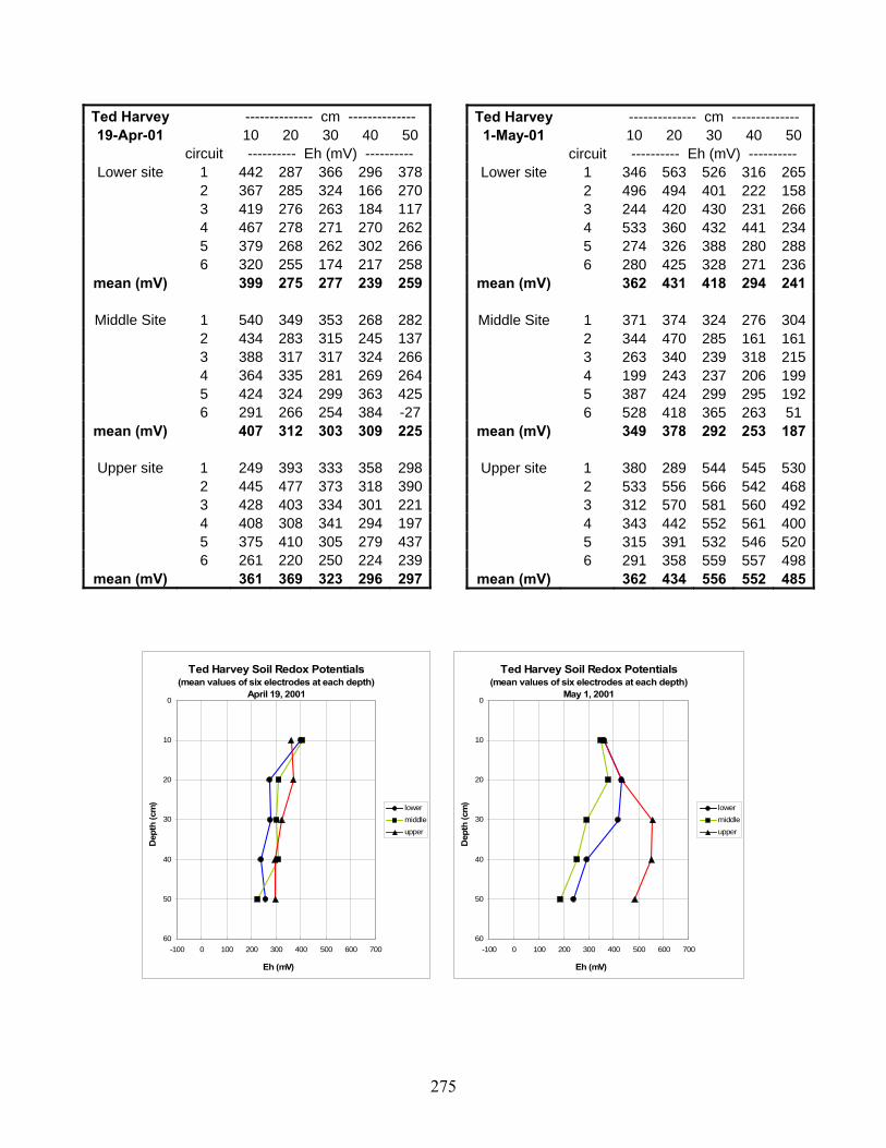
275
Ted Harvey -------------- cm -------------- 19-Apr-01 10 20 30 40 50
circuit ---------- Eh (mV) ---------- Lower site 1 442 287 366 296 378
2 367 285 324 166 270 3 419 276 263 184 117 4 467 278 271 270 262 5 379 268 262 302 266 6 320 255 174 217 258
mean (mV) 399 275 277 239 259
Middle Site 1 540 349 353 268 282 2 434 283 315 245 137 3 388 317 317 324 266 4 364 335 281 269 264 5 424 324 299 363 425 6 291 266 254 384 -27
mean (mV) 407 312 303 309 225
Upper site 1 249 393 333 358 298 2 445 477 373 318 390 3 428 403 334 301 221 4 408 308 341 294 197 5 375 410 305 279 437 6 261 220 250 224 239
mean (mV) 361 369 323 296 297
Ted Harvey Soil Redox Potentials(mean values of six electrodes at each depth)
April 19, 20010
10
20
30
40
50
60-100 0 100 200 300 400 500 600 700
Eh (mV)
Dep
th (c
m)
lowermiddleupper
Ted Harvey Soil Redox Potentials(mean values of six electrodes at each depth)
May 1, 20010
10
20
30
40
50
60-100 0 100 200 300 400 500 600 700
Eh (mV)
Dep
th (c
m)
lowermiddleupper
Ted Harvey -------------- cm -------------- 1-May-01 10 20 30 40 50
circuit ---------- Eh (mV) ---------- Lower site 1 346 563 526 316 265
2 496 494 401 222 158 3 244 420 430 231 266 4 533 360 432 441 234 5 274 326 388 280 288 6 280 425 328 271 236
mean (mV) 362 431 418 294 241
Middle Site 1 371 374 324 276 304 2 344 470 285 161 161 3 263 340 239 318 215 4 199 243 237 206 199 5 387 424 299 295 192 6 528 418 365 263 51
mean (mV) 349 378 292 253 187
Upper site 1 380 289 544 545 530 2 533 556 566 542 468 3 312 570 581 560 492 4 343 442 552 561 400 5 315 391 532 546 520 6 291 358 559 557 498
mean (mV) 362 434 556 552 485

276
Ted Harvey -------------- cm -------------- 16-May-01 10 20 30 40 50
circuit ---------- Eh (mV) ---------- Lower site 1 531 582 594 603 567
2 499 562 572 595 595 3 503 583 585 589 570 4 522 552 573 585 504 5 499 496 567 582 570 6 517 539 578 560 565
mean (mV) 512 552 578 586 562
Middle Site 1 582 588 581 592 607 2 579 566 592 575 529 3 581 560 561 600 595 4 530 532 559 570 519 5 551 550 587 594 611 6 558 577 596 640 634
mean (mV) 564 562 579 595 583
Upper site 1 585 579 630 611 628 2 544 628 593 624 636 3 535 567 584 599 603 4 540 573 594 570 578 5 586 627 631 635 637 6 587 623 621 631 632
mean (mV) 563 600 609 612 619
Ted Harvey Soil Redox Potentials(mean values of six electrodes at each depth)
May 16, 20010
10
20
30
40
50
60-100 0 100 200 300 400 500 600 700
Eh (mV)
Dep
th (c
m)
lowermiddleupper
Ted Harvey Soil Redox Potentials(mean values of six electrodes at each depth)
May 30, 20010
10
20
30
40
50
60-100 0 100 200 300 400 500 600 700
Eh (mV)
Dep
th (c
m)
lowermiddleupper
Ted Harvey -------------- cm -------------- 30-May-01 10 20 30 40 50
circuit ---------- Eh (mV) ---------- Lower site 1 501 569 567 593 370
2 513 568 584 558 531 3 409 543 604 573 513 4 370 529 573 488 201 5 397 521 538 531 162 6 422 480 461 466 421
mean (mV) 435 535 555 535 366
Middle Site 1 562 402 560 581 587 2 425 451 511 533 509 3 517 515 565 537 510 4 386 544 550 512 570 5 475 424 515 580 578 6 447 510 488 601 603
mean (mV) 469 474 532 557 560
Upper site 1 570 542 579 598 573 2 550 548 555 596 595 3 575 544 580 557 592 4 542 555 593 592 541 5 557 580 614 625 633 6 543 586 547 602 596
mean (mV) 556 559 578 595 588
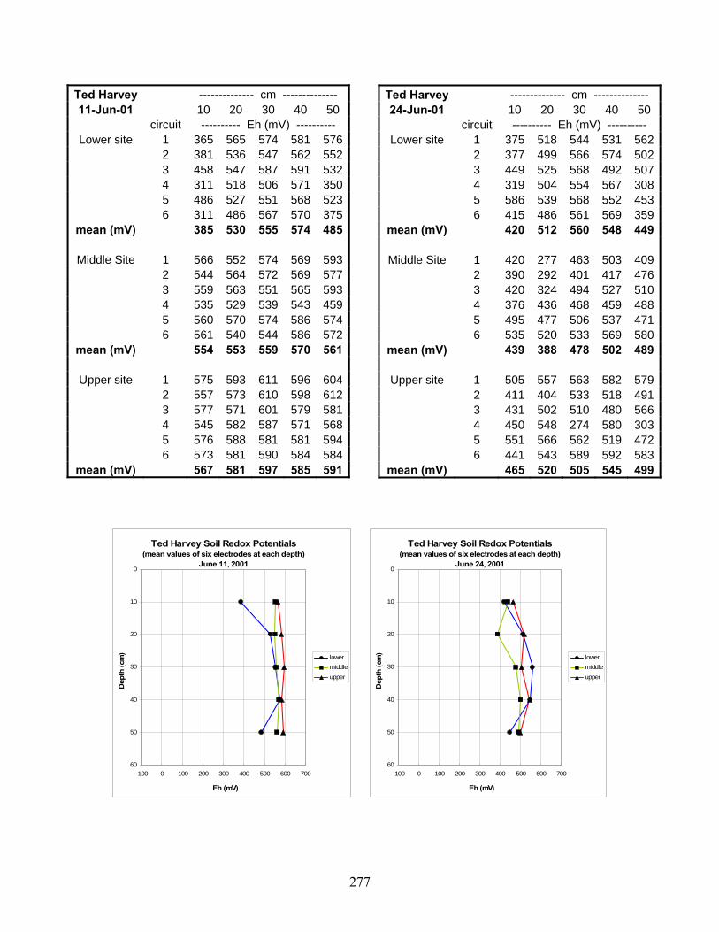
277
Ted Harvey -------------- cm -------------- 11-Jun-01 10 20 30 40 50
circuit ---------- Eh (mV) ---------- Lower site 1 365 565 574 581 576
2 381 536 547 562 552 3 458 547 587 591 532 4 311 518 506 571 350 5 486 527 551 568 523 6 311 486 567 570 375
mean (mV) 385 530 555 574 485
Middle Site 1 566 552 574 569 593 2 544 564 572 569 577 3 559 563 551 565 593 4 535 529 539 543 459 5 560 570 574 586 574 6 561 540 544 586 572
mean (mV) 554 553 559 570 561
Upper site 1 575 593 611 596 604 2 557 573 610 598 612 3 577 571 601 579 581 4 545 582 587 571 568 5 576 588 581 581 594 6 573 581 590 584 584
mean (mV) 567 581 597 585 591
Ted Harvey Soil Redox Potentials(mean values of six electrodes at each depth)
June 11, 20010
10
20
30
40
50
60-100 0 100 200 300 400 500 600 700
Eh (mV)
Dep
th (c
m)
lowermiddleupper
Ted Harvey Soil Redox Potentials(mean values of six electrodes at each depth)
June 24, 20010
10
20
30
40
50
60-100 0 100 200 300 400 500 600 700
Eh (mV)
Dep
th (c
m)
lowermiddleupper
Ted Harvey -------------- cm -------------- 24-Jun-01 10 20 30 40 50
circuit ---------- Eh (mV) ---------- Lower site 1 375 518 544 531 562
2 377 499 566 574 502 3 449 525 568 492 507 4 319 504 554 567 308 5 586 539 568 552 453 6 415 486 561 569 359
mean (mV) 420 512 560 548 449
Middle Site 1 420 277 463 503 409 2 390 292 401 417 476 3 420 324 494 527 510 4 376 436 468 459 488 5 495 477 506 537 471 6 535 520 533 569 580
mean (mV) 439 388 478 502 489
Upper site 1 505 557 563 582 579 2 411 404 533 518 491 3 431 502 510 480 566 4 450 548 274 580 303 5 551 566 562 519 472 6 441 543 589 592 583
mean (mV) 465 520 505 545 499

278
Ted Harvey -------------- cm -------------- 9-Jul-01 10 20 30 40 50
circuit ---------- Eh (mV) ---------- Lower site 1 570 583 583 612 602
2 568 590 619 623 634 3 527 576 611 617 617 4 497 573 593 612 609 5 575 592 615 617 595 6 565 610 632 622 562
mean (mV) 550 587 609 617 603
Middle Site 1 585 577 604 568 618 2 594 594 631 636 634 3 567 605 629 623 623 4 596 602 611 606 595 5 598 575 636 637 579 6 582 570 632 643 626
mean (mV) 587 587 624 619 613
Upper site 1 591 599 633 632 638 2 568 612 635 627 649 3 599 616 632 641 645 4 578 615 623 633 635 5 562 592 613 587 596 6 575 596 602 616 632
mean (mV) 579 605 623 623 633
Ted Harvey Soil Redox Potentials(mean values of six electrodes at each depth)
July 9, 20010
10
20
30
40
50
60-100 0 100 200 300 400 500 600 700
Eh (mV)
Dep
th (c
m)
lowermiddleupper
Ted Harvey Soil Redox Potentials(mean values of six electrodes at each depth)
June 20, 20010
10
20
30
40
50
60-100 0 100 200 300 400 500 600 700
Eh (mV)
Dep
th (c
m)
lowermiddleupper
Ted Harvey -------------- cm -------------- 20-Jul-01 10 20 30 40 50
circuit ---------- Eh (mV) ---------- Lower site 1 576 609 628 642 639
2 557 600 629 643 618 3 578 598 623 626 643 4 581 596 597 604 621 5 563 599 627 603 616 6 590 618 617 655 655
mean (mV) 574 603 620 629 632
Middle Site 1 596 601 501 2 615 504 637 3 580 603 634 645 4 591 604 627 5 611 622 636 6 611 595 639 640
mean (mV) 601 588 612 643
Upper site 1 2 3 4 5 6
mean (mV)

279
Ted Harvey -------------- cm -------------- 10-Jan-02 10 20 30 40 50
circuit ---------- Eh (mV) ---------- Lower site 1 578 590 603 604 587
2 587 598 607 609 591 3 574 584 594 599 601 4 580 623 599 591 612 5 583 590 589 598 612 6 581 592 577 594 600
mean (mV) 581 596 595 599 601
Middle Site 1 585 598 614 609 618 2 596 626 613 612 610 3 601 622 611 571 594 4 586 601 585 590 596 5 601 611 598 590 591 6 571 609 605 607 619
mean (mV) 590 611 604 597 605
Upper site 1 585 634 625 2 586 612 597 631 3 476 470 464 4 608 613 626 638 5 599 622 635 6 598 613 636 638
mean (mV) 575 594 597 636
Ted Harvey Soil Redox Potentials(mean values of six electrodes at each depth)
January 10, 20020
10
20
30
40
50
60-100 0 100 200 300 400 500 600 700
Eh (mV)
Dep
th (c
m)
lowermiddleupper
Ted Harvey Soil Redox Potentials(mean values of six electrodes at each depth)
Februrary 3, 20020
10
20
30
40
50
60-100 0 100 200 300 400 500 600 700
Eh (mV)
Dep
th (c
m)
lowermiddleupper
Ted Harvey -------------- cm -------------- 3-Feb-02 10 20 30 40 50
circuit ---------- Eh (mV) ---------- Lower site 1 567 582 592 578 512
2 573 571 600 586 590 3 568 579 587 594 589 4 562 592 614 581 599 5 559 575 586 606 585 6 558 574 581 595 579
mean (mV) 565 579 593 590 576
Middle Site 1 569 593 608 600 605 2 590 608 619 627 616 3 590 615 614 617 607 4 596 640 615 619 609 5 591 612 616 613 603 6 598 613 605 615 609
mean (mV) 589 614 613 615 608
Upper site 1 585 600 618 617 640 2 595 621 639 646 621 3 603 602 638 627 625 4 597 606 625 629 615 5 605 614 623 633 627 6 596 608 620 634 612
mean (mV) 597 609 627 631 623

280
Ted Harvey -------------- cm -------------- 17-Feb-02 10 20 30 40 50
circuit ---------- Eh (mV) ---------- Lower site 1 574 594 598 591 590
2 565 579 582 580 576 3 562 586 593 587 565 4 559 581 588 565 580 5 562 585 508 575 577 6 558 573 593 583 578
mean (mV) 563 583 577 580 578
Middle Site 1 591 596 611 614 591 2 579 598 578 593 584 3 570 593 603 575 586 4 577 612 622 614 609 5 579 601 605 617 598 6 579 615 626 622 612
mean (mV) 579 603 608 606 597
Upper site 1 614 635 637 615 602 2 599 608 605 614 604 3 596 620 635 613 605 4 594 625 633 623 616 5 589 620 627 606 609 6 597 616 629 589 596
mean (mV) 598 621 628 610 605
Ted Harvey Soil Redox Potentials(mean values of six electrodes at each depth)
February 17, 20020
10
20
30
40
50
60-100 0 100 200 300 400 500 600 700
Eh (mV)
Dep
th (c
m)
lowermiddleupper
Ted Harvey Soil Redox Potentials(mean values of six electrodes at each depth)
March 3, 20020
10
20
30
40
50
60-100 0 100 200 300 400 500 600 700
Eh (mV)
Dep
th (c
m)
lowermiddleupper
Ted Harvey -------------- cm -------------- 3-Mar-02 10 20 30 40 50
circuit ---------- Eh (mV) ---------- Lower site 1 577 587 586 550 563
2 578 604 605 568 554 3 571 593 592 583 561 4 554 584 594 575 550 5 565 592 602 573 548 6 576 597 593 564 563
mean (mV) 570 593 595 569 557
Middle Site 1 576 586 589 583 575 2 587 599 604 604 591 3 580 599 609 603 588 4 568 586 596 606 571 5 573 585 606 604 586 6 577 593 603 593 582
mean (mV) 577 591 601 599 582
Upper site 1 604 628 636 644 635 2 619 611 633 636 633 3 606 618 623 629 614 4 601 606 619 623 619 5 611 612 625 626 627 6 615 625 627 633 623
mean (mV) 609 617 627 632 625

281
Ted Harvey -------------- cm -------------- 30-Mar-02 10 20 30 40 50
circuit ---------- Eh (mV) ---------- Lower site 1 342 571 581 590 528
2 351 551 585 560 489 3 360 565 584 556 525 4 341 549 577 567 465 5 346 555 583 564 515 6
mean (mV) 348 558 582 567 504
Middle Site 1 342 577 609 594 575 2 373 560 603 602 575 3 365 563 607 598 579 4 359 562 595 604 573 5 355 566 599 589 577 6
mean (mV) 359 566 603 597 576
Upper site 1 600 605 628 628 611 2 585 621 641 633 605 3 598 601 624 583 547 4 595 609 626 615 573 5 588 618 623 603 565 6
mean (mV) 593 611 628 612 580
Ted Harvey Soil Redox Potentials(mean values of six electrodes at each depth)
March 30, 20020
10
20
30
40
50
60-100 0 100 200 300 400 500 600 700
Eh (mV)
Dep
th (c
m)
lowermiddleupper
Ted Harvey Soil Redox Potentials(mean values of six electrodes at each depth)
May 10, 20020
10
20
30
40
50
60-100 0 100 200 300 400 500 600 700
Eh (mV)
Dep
th (c
m)
lowermiddleupper
Ted Harvey -------------- cm -------------- 10-May-02 10 20 30 40 50
circuit ---------- Eh (mV) ---------- Lower site 1 336 464 312 289 289
2 395 324 533 358 314 3 389 334 333 320 311 4 329 331 283 249 253 5 313 452 513 509 292 6 296 304 227 280 235
mean (mV) 343 368 367 334 282
Middle Site 1 499 585 403 303 310 2 569 456 529 342 190 3 547 499 487 430 410 4 321 430 254 253 215 5 409 453 273 355 336 6 500 444 274 283 325
mean (mV) 474 478 370 328 298
Upper site 1 354 450 491 542 345 2 393 510 572 491 449 3 564 573 583 520 328 4 491 499 496 485 394 5 6 511 532 541 443 446
mean (mV) 463 513 537 496 392

282
Ted Harvey -------------- cm -------------- 28-May-02 10 20 30 40 50
circuit ---------- Eh (mV) ---------- Lower site 1 521 559 584 564 447
2 533 542 561 560 367 3 523 552 581 567 355 4 550 520 559 568 372 5 555 565 552 571 462 6 573 568 584 585 366
mean (mV) 543 551 570 569 395
Middle Site 1 584 595 608 621 599 2 555 586 604 605 600 3 571 592 610 599 593 4 587 585 603 628 621 5 575 595 607 616 605 6 584 604 615 614 603
mean (mV) 576 593 608 614 604
Upper site 1 572 518 569 571 573 2 521 525 559 571 550 3 551 546 544 584 591 4 563 512 576 585 575 5 539 554 572 576 580 6 545 543 554 581 561
mean (mV) 549 533 562 578 572
Ted Harvey Soil Redox Potentials(mean values of six electrodes at each depth)
May 28, 20020
10
20
30
40
50
60-100 0 100 200 300 400 500 600 700
Eh (mV)
Dep
th (c
m)
lowermiddleupper
Ted Harvey Soil Redox Potentials(mean values of six electrodes at each depth)
October 13, 20020
10
20
30
40
50
60-100 0 100 200 300 400 500 600 700
Eh (mV)
Dep
th (c
m)
lowermiddleupper
Ted Harvey -------------- cm -------------- 13-Oct-02 10 20 30 40 50
circuit ---------- Eh (mV) ---------- Lower site 1 554 580 570 603 622
2 500 562 588 610 621 3 588 573 586 608 610 4 619 588 609 607 611 5 573 574 580 593 605 6 595 563 601 606 612
mean (mV) 572 573 589 605 614
Middle Site 1 580 593 589 624 634 2 575 595 576 627 632 3 597 596 613 621 636 4 522 561 558 591 625 5 592 576 604 625 630 6 603 584 573 610 635
mean (mV) 578 584 586 616 632
Upper site 1 624 624 632 611 620 2 604 613 627 635 622 3 605 620 630 623 629 4 617 630 642 642 625 5 625 615 633 635 618 6 621 619 632 630 635
mean (mV) 616 620 633 629 625

283
Ted Harvey -------------- cm -------------- 1-Dec-02 10 20 30 40 50
circuit ---------- Eh (mV) ---------- Lower site 1 569 365 300 306 286
2 520 343 260 305 275 3 537 347 330 323 285 4 565 362 327 324 305 5 491 395 280 319 276 6 566 364 335 310 310
mean (mV) 541 363 305 315 290
Middle Site 1 614 599 551 582 548 2 571 559 532 571 536 3 614 424 450 461 446 4 582 424 526 552 549 5 584 471 520 526 491 6 574 565 515 551 512
mean (mV) 590 507 516 541 514
Upper site 1 622 414 532 528 328 2 616 418 519 399 389 3 518 293 375 282 273 4 624 523 335 342 315 5 6 641 376 306 297 315
mean (mV) 604 405 413 370 324
Ted Harvey Soil Redox Potentials(mean values of six electrodes at each depth)
December 1, 20020
10
20
30
40
50
60-100 0 100 200 300 400 500 600 700
Eh (mV)
Dep
th (c
m)
lowermiddleupper
Ted Harvey Soil Redox Potentials(mean values of six electrodes at each depth)
January 12, 20030
10
20
30
40
50
60-100 0 100 200 300 400 500 600 700
Eh (mV)
Dep
th (c
m)
lowermiddleupper
Ted Harvey -------------- cm -------------- 12-Jan-03 10 20 30 40 50
circuit ---------- Eh (mV) ---------- Lower site 1 269 233 170 236 250
2 319 209 140 233 190 3 320 250 174 259 244 4 329 248 285 293 253 5 346 255 258 307 215 6
mean (mV) 317 239 205 266 230
Middle Site 1 559 495 335 393 273 2 579 514 310 273 288 3 565 521 273 316 246 4 552 476 310 279 244 5 585 540 364 385 285 6
mean (mV) 568 509 318 329 267
Upper site 1 555 564 470 287 256 2 589 506 356 212 232 3 580 535 413 213 364 4 567 499 271 232 244 5 617 515 267 211 278 6
mean (mV) 582 524 355 231 275

284
Ted Harvey -------------- cm -------------- 8-Feb-03 10 20 30 40 50
circuit ---------- Eh (mV) ---------- Lower site 1 214 241 -16 156 228
2 198 239 175 209 232 3 242 214 162 180 239 4 251 255 168 182 245 5 285 94 102 230 286 6
mean (mV) 238 209 118 191 246
Middle Site 1 219 195 193 170 218 2 253 209 232 220 241 3 231 183 214 55 149 4 178 231 199 172 232 5 277 245 243 90 262 6
mean (mV) 232 213 216 141 220
Upper site 1 589 562 252 201 195 2 584 478 302 259 208 3 585 449 277 243 205 4 586 592 289 242 228 5 563 430 282 246 231 6
mean (mV) 581 502 280 238 213
Ted Harvey Soil Redox Potentials(mean values of six electrodes at each depth)
February 8, 20030
10
20
30
40
50
60-100 0 100 200 300 400 500 600 700
Eh (mV)
Dep
th (c
m)
lowermiddleupper
Ted Harvey Soil Redox Potentials(mean values of six electrodes at each depth)
March 4, 20030
10
20
30
40
50
60-100 0 100 200 300 400 500 600 700
Eh (mV)
Dep
th (c
m)
lowermiddleupper
Ted Harvey -------------- cm -------------- 4-Mar-03 10 20 30 40 50
circuit ---------- Eh (mV) ---------- Lower site 1 463 506 506 301 269
2 538 532 395 348 302 3 487 460 534 333 259 4 510 561 575 537 312 5 517 565 585 497 289 6 362 576 551 549 334
mean (mV) 480 533 524 428 294
Middle Site 1 365 550 507 303 219 2 352 513 872 271 209 3 330 539 425 273 254 4 315 581 426 395 318 5 368 522 458 271 276 6 370 551 579 316 261
mean (mV) 350 543 545 305 256
Upper site 1 346 573 583 306 274 2 412 566 590 529 297 3 409 599 606 315 288 4 404 610 610 458 279 5 365 604 584 307 265 6 364 567 571 315 261
mean (mV) 383 587 591 372 277

285
Ted Harvey -------------- cm -------------- 25-Mar-03 10 20 30 40 50
circuit ---------- Eh (mV) ---------- Lower site 1 393 314 255 258 224
2 3 365 301 263 299 244 4 376 314 282 281 232 5 364 330 290 269 252 6 384 320 134 199 234
mean (mV) 376 316 245 261 237
Middle Site 1 339 268 539 542 312 2 3 374 332 589 567 306 4 352 310 567 538 300 5 325 366 572 562 354 6 364 352 586 566 302
mean (mV) 351 326 571 555 315
Upper site 1 498 359 535 528 385 2 3 637 459 577 556 345 4 555 439 573 435 296 5 616 433 584 558 343 6 619 451 574 549 332
mean (mV) 585 428 569 525 340
Ted Harvey Soil Redox Potentials(mean values of six electrodes at each depth)
March 25, 20030
10
20
30
40
50
60-100 0 100 200 300 400 500 600 700
Eh (mV)
Dep
th (c
m)
lowermiddleupper
Ted Harvey Soil Redox Potentials(mean values of six electrodes at each depth)
April 4, 20030
10
20
30
40
50
60-100 0 100 200 300 400 500 600 700
Eh (mV)
Dep
th (c
m)
lowermiddleupper
Ted Harvey -------------- cm -------------- 4-Apr-03 10 20 30 40 50
circuit ---------- Eh (mV) ---------- Lower site 1 491 335 294 328 323
2 3 352 322 294 318 283 4 420 333 317 322 264 5 374 347 328 317 273 6 276 286 265 262 269
mean (mV) 383 325 300 309 282
Middle Site 1 361 314 439 305 238 2 3 385 322 519 356 239 4 407 287 360 338 312 5 567 366 430 488 337 6 319 261 347 278 227
mean (mV) 408 310 419 353 271
Upper site 1 361 318 457 509 285 2 3 426 260 529 482 302 4 631 364 469 497 261 5 419 200 534 317 254 6 371 273 504 311 252
mean (mV) 442 283 499 423 271

286
Ted Harvey -------------- cm -------------- 2-May-03 10 20 30 40 50
circuit ---------- Eh (mV) ---------- Lower site 1 318 361 261 270 281
2 296 434 238 234 210 3 317 450 309 249 273 4 346 530 343 283 251 5 303 354 306 304 293 6
mean (mV) 316 426 291 268 262
Middle Site 1 390 592 560 379 335 2 504 534 532 273 248 3 593 608 560 290 293 4 571 581 538 351 291 5 595 594 557 350 291 6
mean (mV) 531 582 549 329 292
Upper site 1 524 379 272 285 262 2 554 155 216 209 200 3 439 136 158 230 250 4 424 355 302 283 256 5 510 498 497 481 305 6
mean (mV) 490 305 289 298 255
Ted Harvey Soil Redox Potentials(mean values of six electrodes at each depth)
May 2, 20030
10
20
30
40
50
60-100 0 100 200 300 400 500 600 700
Eh (mV)
Dep
th (c
m)
lowermiddleupper
Ted Harvey Soil Redox Potentials(mean values of six electrodes at each depth)
May 20, 20030
10
20
30
40
50
60-100 0 100 200 300 400 500 600 700
Eh (mV)
Dep
th (c
m)
lowermiddleupper
Ted Harvey -------------- cm -------------- 20-May-03 10 20 30 40 50
circuit ---------- Eh (mV) ---------- Lower site 1 258 265 256 259 213
2 247 283 255 257 231 3 449 477 275 235 229 4 291 237 229 213 228 5 254 270 227 321 236 6
mean (mV) 300 306 248 257 227
Middle Site 1 270 549 605 601 441 2 343 591 619 611 320 3 240 457 529 491 253 4 526 581 602 552 238 5 366 577 594 541 302 6
mean (mV) 349 551 590 559 311
Upper site 1 374 224 556 591 430 2 384 300 545 549 318 3 361 309 556 595 403 4 317 257 387 400 215 5 456 317 559 568 339 6
mean (mV) 378 281 521 541 341
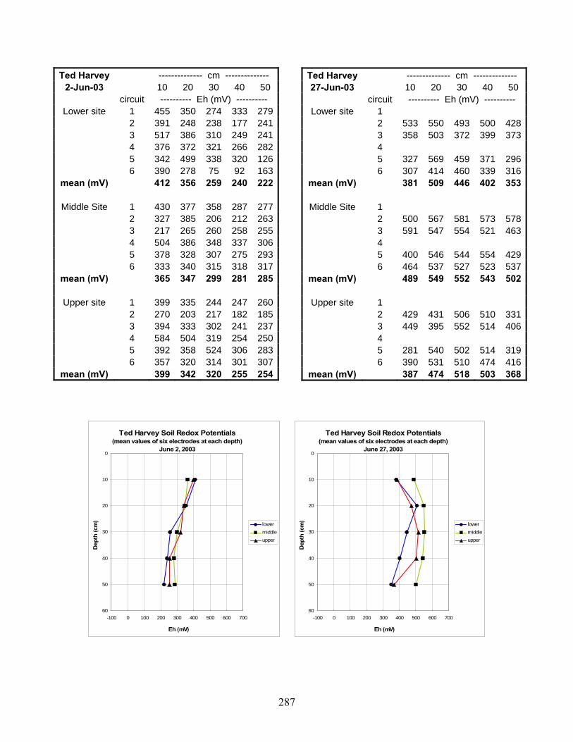
287
Ted Harvey -------------- cm -------------- 2-Jun-03 10 20 30 40 50
circuit ---------- Eh (mV) ---------- Lower site 1 455 350 274 333 279
2 391 248 238 177 241 3 517 386 310 249 241 4 376 372 321 266 282 5 342 499 338 320 126 6 390 278 75 92 163
mean (mV) 412 356 259 240 222
Middle Site 1 430 377 358 287 277 2 327 385 206 212 263 3 217 265 260 258 255 4 504 386 348 337 306 5 378 328 307 275 293 6 333 340 315 318 317
mean (mV) 365 347 299 281 285
Upper site 1 399 335 244 247 260 2 270 203 217 182 185 3 394 333 302 241 237 4 584 504 319 254 250 5 392 358 524 306 283 6 357 320 314 301 307
mean (mV) 399 342 320 255 254
Ted Harvey Soil Redox Potentials(mean values of six electrodes at each depth)
June 2, 20030
10
20
30
40
50
60-100 0 100 200 300 400 500 600 700
Eh (mV)
Dep
th (c
m)
lowermiddleupper
Ted Harvey Soil Redox Potentials(mean values of six electrodes at each depth)
June 27, 20030
10
20
30
40
50
60-100 0 100 200 300 400 500 600 700
Eh (mV)
Dep
th (c
m)
lowermiddleupper
Ted Harvey -------------- cm -------------- 27-Jun-03 10 20 30 40 50
circuit ---------- Eh (mV) ---------- Lower site 1
2 533 550 493 500 428 3 358 503 372 399 373 4 5 327 569 459 371 296 6 307 414 460 339 316
mean (mV) 381 509 446 402 353
Middle Site 1 2 500 567 581 573 578 3 591 547 554 521 463 4 5 400 546 544 554 429 6 464 537 527 523 537
mean (mV) 489 549 552 543 502
Upper site 1 2 429 431 506 510 331 3 449 395 552 514 406 4 5 281 540 502 514 319 6 390 531 510 474 416
mean (mV) 387 474 518 503 368

288
Ted Harvey -------------- cm -------------- 18-Jul-03 10 20 30 40 50
circuit ---------- Eh (mV) ---------- Lower site 1 571 578 586 559 510
2 576 574 579 580 519 3 557 594 586 571 327 4 479 560 563 590 460 5 553 545 552 573 442 6
mean (mV) 547 570 573 575 452
Middle Site 1 2 571 587 555 596 601 3 571 592 601 612 593 4 557 589 606 612 611 5 483 589 599 606 619 6 558 585 563 591 580
mean (mV) 548 588 585 603 601
Upper site 1 2 484 561 583 612 592 3 480 592 601 610 641 4 538 578 598 613 610 5 544 602 608 612 611 6 561 572 581 583 582
mean (mV) 521 581 594 606 607
Ted Harvey Soil Redox Potentials(mean values of six electrodes at each depth)
July 18, 20030
10
20
30
40
50
60-100 0 100 200 300 400 500 600 700
Eh (mV)
Dep
th (c
m)
lowermiddleupper
Ted Harvey Soil Redox Potentials(mean values of six electrodes at each depth)
August 20, 20030
10
20
30
40
50
60-100 0 100 200 300 400 500 600 700
Eh (mV)
Dep
th (c
m)
lowermiddleupper
Ted Harvey -------------- cm -------------- 20-Aug-03 10 20 30 40 50
circuit ---------- Eh (mV) ---------- Lower site 1
2 617 603 615 632 601 3 584 588 568 595 438 4 571 560 593 603 591 5 571 586 592 586 401 6 580 567 579 573 583
mean (mV) 585 581 589 598 523
Middle Site 1 2 613 620 633 649 658 3 622 248 644 671 656 4 591 573 620 645 639 5 621 636 652 648 668 6 629 605 623 640 635
mean (mV) 615 536 634 651 651
Upper site 1 2 614 619 622 636 642 3 532 590 632 648 656 4 469 600 639 645 638 5 569 581 637 645 645 6 534 595 628 643 646
mean (mV) 544 597 632 643 645

289
Appendix G: Soil Temperature Data at 10 cm, 30 cm, and 50 cm NOTE: Soil temperature logger for the Eastern Neck Island site was not recovered

290

291

292
Appendix H: Air Temperatures at Eastern Neck Island site. NOTE: Data from Blackwater and Isle of Wight sites not recovered; data from Ted Harvey site not shown.

293
Appendix I: Vegetation Analysis
Vegetation Analysis August 22, 2002 Site: Blackwater – middle Describers: Dr. Martin Rabenhorst Al Rizzo Philip Zurheide Karen Castenson Robert Vaughan Dominance of species by order of listing Tree stratum Status Loblolly Pine Pinus taeda FAC- Sapling stratum (none) Shrub stratum Loblolly Pine Pinus taeda FAC- Eastern Baccharis/High-Tide Bush Baccharis halimifolia FACW Common Persimmon Diospyros virginiana FAC- Herbaceous stratum Common Reed Phragmites australis FACW Switchgrass Panicum virgatum FAC Saltmarsh Fleabane Pluchea camphorata FACW Sedge Cyperus sp. Halberd-leaved Tearthumb Polygonum arifolium OBL Softrush Juncus effusus FACW+ Woody Vine stratum Greenbriar Smilax rotundifolia FAC Poison Ivy Toxicodendron radicans FAC

294
Vegetation Analysis August 22, 2002 Site: Blackwater – upper Describers: Dr. Martin Rabenhorst Al Rizzo Philip Zurheide Karen Castenson Robert Vaughan Dominance of species by order of listing Tree stratum Status Loblolly Pine Pinus taeda FAC- Black Gum Nyssa sylvatica FAC Sweet Gum Liquidambar styraciflua FAC Willow Oak Quercus phellos FAC+ Sapling stratum Southern Red Oak Quercus falcata FACU- Northern Red Oak Quercus rubra FACU- Shrub stratum Wax Myrtle Myrica cerifera FAC Willow Oak Quercus phellos FAC+ Eastern Baccharis/High-Tide Bush Baccharis halimifolia FACW Loblolly Pine Pinus taeda FAC- American Holly Ilex opaca FACU+ Common Persimmon Diospyros virginiana FAC- Herbaceous stratum Spike Grass Distichlis spicata FACW+ Saltmarsh Fleabane Pluchea camphorata FACW Blackberry Prickly Lettuce (disturbed area) Lactuca serriola FAC- Woody Vine stratum Greenbriar Smilax rotundifolia FAC Poison Ivy Toxicodendron radicans FAC

295
Vegetation Analysis August 22, 2002 Site: Isle of Wight – lower Describers: Dr. Martin Rabenhorst Al Rizzo Philip Zurheide Karen Castenson Robert Vaughan Dominance of species by order of listing Tree stratum Status Loblolly Pine Pinus taeda FAC- Willow Oak Quercus phellos FAC+ Black Gum Nyssa sylvatica FAC Sweet Gum Liquidambar styraciflua FAC Swamp White Oak Quercus bicolor FACW+ Sapling stratum Sweet Gum Liquidambar styraciflua FAC Wax Myrtle Myrica cerifera FAC Shrub stratum Loblolly Pine Pinus taeda FAC- Wax Myrtle Myrica cerifera FAC Eastern Baccharis/High-Tide Bush Baccharis halimifolia FACW Jesuit's Bark/Marsh-Elder Iva frutescens FACW+ Herbaceous stratum Common Reed Phragmites australis FACW Switchgrass Panicum virgatum FAC Saltmeadow Cordgrass Spartina patens FACW+ Seaside Goldenrod Solidago sempervirens FACW Panic Grass Dichanthelium FAC Soft Rush Juncus effusus FACW+ Woody Vine stratum Greenbriar Smilax rotundifolia FAC Poison Ivy Toxicodendron radicans FAC

296
Vegetation Analysis August 22, 2002 Site: Isle of Wight – middle Describers: Dr. Martin Rabenhorst Al Rizzo Philip Zurheide Karen Castenson Robert Vaughan Dominance of species by order of listing Tree stratum Status Swamp White Oak Quercus bicolor FACW+ Pignut Hickory Carya glabra FACU- Sweet Gum Liquidambar styraciflua FAC White Oak Quercus alba FACU- Black Gum Nyssa sylvatica FAC Sapling stratum Sweet Gum Liquidambar styraciflua FAC Swamp White Oak Quercus bicolor FACW+ Shrub stratum Loblolly Pine Pinus taeda FAC- American Holly Ilex opaca FACU+ Sweet Gum Liquidambar styraciflua FAC Southern Arrowwood Viburnum dentatum FAC Highbush Blueberry Vaccinium corymbosum FACW- Herbaceous stratum Swamp White Oak Quercus bicolor FACW+ Spike Grass/ (Inland Saltgrass?) Distichlis spicata FACW+ Sweetbay Magnolia Magnolia virginiana FACW+ Partridgeberry Mitchella repens FACU Sassafras Lauraceae Sassafras albidum FACU- Cinnamon Fern Osmunda cinnamomea FACW Loblolly Pine Pinus taeda FAC- Woody Vine stratum Greenbriar Smilax rotundifolia FAC Fox Grape Vitis labrusca FACU Japanese Honeysuckle Lonicera japonica FAC-
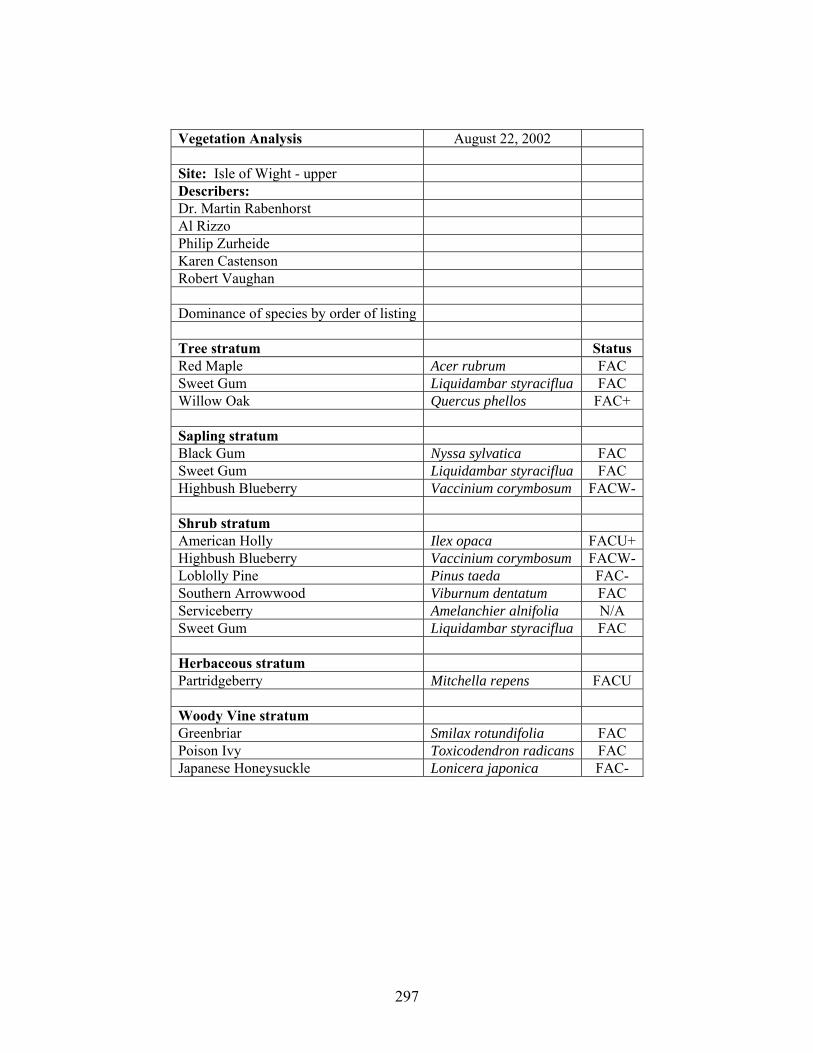
297
Vegetation Analysis August 22, 2002 Site: Isle of Wight - upper Describers: Dr. Martin Rabenhorst Al Rizzo Philip Zurheide Karen Castenson Robert Vaughan Dominance of species by order of listing Tree stratum Status Red Maple Acer rubrum FAC Sweet Gum Liquidambar styraciflua FAC Willow Oak Quercus phellos FAC+ Sapling stratum Black Gum Nyssa sylvatica FAC Sweet Gum Liquidambar styraciflua FAC Highbush Blueberry Vaccinium corymbosum FACW- Shrub stratum American Holly Ilex opaca FACU+ Highbush Blueberry Vaccinium corymbosum FACW- Loblolly Pine Pinus taeda FAC- Southern Arrowwood Viburnum dentatum FAC Serviceberry Amelanchier alnifolia N/A Sweet Gum Liquidambar styraciflua FAC Herbaceous stratum Partridgeberry Mitchella repens FACU Woody Vine stratum Greenbriar Smilax rotundifolia FAC Poison Ivy Toxicodendron radicans FAC Japanese Honeysuckle Lonicera japonica FAC-

298
Vegetation Analysis August 22, 2002 Site: Eastern Neck Island - lower Describers: Dr. Martin Rabenhorst Al Rizzo Philip Zurheide Karen Castenson Robert Vaughan Dominance of species by order of listing Tree stratum Status Black Gum Nyssa sylvatica FAC Red Maple Acer rubrum FAC Northern Red Oak Quercus rubra FACU- Willow Oak Quercus phellos FAC+ Sapling stratum Black Gum Nyssa sylvatica FAC Sweet Gum Liquidambar styraciflua FAC Red Maple Acer rubrum FAC Northern Red Oak Quercus rubra FACU- Willow Oak Quercus phellos FAC+ Pawpaw Asimina triloba FACU+ Shrub stratum (suppressed due to draught) American Holly Ilex opaca FACU+ Pawpaw Asimina triloba FACU+ Herbaceous stratum Spike Grass/ (Inland Saltgrass?) Distichlis spicata FACW+ Partridgeberry Mitchella repens FACU Red Maple Acer rubrum FAC Willow Oak Quercus phellos FAC+ Royal Fern Osmunda regalis OBL Woody Vine stratum Greenbriar Smilax rotundifolia FAC Japanese Honeysuckle Lonicera japonica FAC-

299
Vegetation Analysis August 22, 2002 Site: Eastern Neck Island - middle Describers: Dr. Martin Rabenhorst Al Rizzo Philip Zurheide Karen Castenson Robert Vaughan Dominance of species by order of listing Tree stratum Status Black Gum Nyssa sylvatica FAC Red Maple Acer rubrum FAC Northern Red Oak Quercus rubra FACU- Willow Oak Quercus phellos FAC+ Sapling stratum Black Gum Nyssa sylvatica FAC American Holly Ilex opaca FACU+ Sweet Gum Liquidambar styraciflua FAC Shrub stratum (none) Herbaceous stratum Spike Grass/ (Inland Saltgrass?) Distichlis spicata FACW+ Black Gum Nyssa sylvatica FAC Partridgeberry Mitchella repens FACU Woody Vine stratum Greenbriar Smilax rotundifolia FAC

300
Vegetation Analysis August 22, 2002 Site: Eastern Neck Island - upper Describers: Dr. Martin Rabenhorst Al Rizzo Philip Zurheide Karen Castenson Robert Vaughan Dominance of species by order of listing Tree stratum Status White Oak Quercus alba FACU- Tulip Popler Liriodendron tulipifera FACU Sweet Gum Liquidambar styraciflua FAC Pignut Hickory Carya glabra FACU- Swamp White Oak Quercus bicolor FACW+ Sapling stratum Black Cherry Prunus serotina FACU Pawpaw Asimina triloba FACU+ Shrub stratum (none) Herbaceous stratum False Solomon's Seal Smilacina racemosa FACU- Woody Vine stratum Japanese Honeysuckle Lonicera japonica FAC- NOTE: suppression of under-story plants by grazing

301
Vegetation Analysis August 22, 2002 Site: Ted Harvey - lower Describers: Dr. Martin Rabenhorst Al Rizzo Philip Zurheide Karen Castenson Robert Vaughan Dominance of species by order of listing Tree stratum Status Sweet Gum Liquidambar styraciflua FAC Sapling stratum Common Persimmon Diospyros virginiana FAC- Sweet Gum Liquidambar styraciflua FAC Shrub stratum Eastern Baccharis/High-Tide Bush Baccharis halimifolia FACWSouthern Bayberry/Wax Myrtle Myrica cerifera (Morella cerifera) FAC Winged Sumac Rhus copallinum N/A Common Persimmon Diospyros virginiana FAC-
Staghorn Sumac Rhus hirta (L.) Sudworth/Rhus typhina N/A
Herbaceous stratum Sensitive Fern Onoclea sensibilis FACWRough-stemed Goldenrod/Wrinkle-leaf Goldenrod Solidago rugosa FAC Switchgrass Panicum virgatum FAC Dewberry Blackberry Partridgeberry Mitchella repens FACU Common Reed Phragmites australis FACWSeaside Goldenrod Solidago sempervirens FACWSaltmarsh Fleabane Pluchea camphorata FACW
Dogbane (Climbing Dogbane) Trachelospermum difforme (Walt.) Gray FACW
Woody Vine stratum Coastalplain Tickseed Coreopsis gladiata Walt. FACWPoison Ivy Toxicodendron radicans FAC

302
Vegetation Analysis August 22, 2002 Site: Ted Harvey - middle Describers: Dr. Martin Rabenhorst Al Rizzo Philip Zurheide Karen Castenson Robert Vaughan Dominance of species by order of listing Tree stratum Status Sweet Gum Liquidambar styraciflua FAC Willow Oak Quercus phellos FAC+ Postoak Quercus stellata Wangenh. UPL Sapling stratum Sweet Gum Liquidambar styraciflua FAC Common Persimmon Diospyros virginiana FAC- Shrub stratum Common Persimmon Diospyros virginiana FAC- Herbaceous stratum Dewberry Switchgrass Panicum virgatum FAC Poison Ivy Toxicodendron radicans FAC Common Velvetgrass Holcus lanatus FACU Seaside Goldenrod Solidago sempervirens FACW Woody Vine stratum Japanese Honeysuckle Lonicera japonica FAC- Poison Ivy Toxicodendron radicans FAC

303
Vegetation Analysis August 22, 2002 Site: Ted Harvey - upper Describers: Dr. Martin Rabenhorst Al Rizzo Philip Zurheide Karen Castenson Robert Vaughan Dominance of species by order of listing Tree stratum Status Sweet Gum Liquidambar styraciflua FAC Pin Oak Quercus palustis FACWBlack Gum Nyssa sylvatica FAC Willow Oak Quercus phellos FAC+ Sapling stratum Staghorn Sumac Rhus hirta (L.) Sudworth/Rhus typhina N/A Willow Oak Quercus phellos FAC+ Sweet Gum Liquidambar styraciflua FAC Common Persimmon Diospyros virginiana FAC- Shrub stratum Willow Oak Quercus phellos FAC+ Common Persimmon Diospyros virginiana FAC- Eastern Baccharis/High-Tide Bush Baccharis halimifolia FACWSouthern Arrowwood Viburnum dentatum FAC Herbaceous stratum Blackberry Switchgrass Panicum virgatum FAC Deer tongue Dichanthelium clandestinum (L.) Gould FAC+ Seaside Goldenrod Solidago sempervirens FACWCommon Velvetgrass Holcus lanatus FACU Common Persimmon Diospyros virginiana FAC- Woody Vine stratum Japanese Honeysuckle Lonicera japonica FAC- Poison Ivy Toxicodendron radicans FAC Dewberry Cat Greenbrier Smilax glauca FACU

304
Appendix J: Mesocosm Leached Iron
Column #9(Leached Control)
0255075
100125150175200225
4-Apr 2-May 30-May 27-Jun 25-Jul 22-Aug 19-Sep
Leac
hate
Iron
(mg/
L)
Column #2(Leached Control)
0255075
100125150175200225250275
4-Apr 2-May 30-May 27-Jun 25-Jul 22-Aug 19-Sep
Leac
hate
Iron
(mg/
L)
Column #8(Leached Control)
0255075
100125150175200225250275
4-Apr 2-May 30-May 27-Jun 25-Jul 22-Aug 19-Sep
Leac
hate
Iron
(mg/
L)

305
Column #6(Dextrose)
0255075
100125150175200225
4-Apr 2-May 30-May 27-Jun 25-Jul 22-Aug 19-Sep
Leac
hate
Iron
(mg/
L)
Column #12(Dextrose)
0255075
100125150175200225250275
4-Apr 2-May 30-May 27-Jun 25-Jul 22-Aug 19-Sep
Leac
hate
Iron
(mg/
L)
Column #5(Dextrose)
0255075
100125150175200225250275
4-Apr 2-May 30-May 27-Jun 25-Jul 22-Aug 19-Sep
Leac
hate
Iron
(mg/
L)

306
Column #7(Leaves)
0255075
100125150175200225250275
4-Apr 2-May 30-May 27-Jun 25-Jul 22-Aug 19-Sep
Leac
hate
Iron
(mg/
L)
Column #10(Leaves)
0255075
100125150175200225250275
4-Apr 2-May 30-May 27-Jun 25-Jul 22-Aug 19-Sep
Leac
hate
Iron
(mg/
L)
Column #11(Leaves)
0255075
100125150175200225
4-Apr 2-May 30-May 27-Jun 25-Jul 22-Aug 19-Sep
Leac
hate
Iron
(mg/
L)

307
Appendix K: Site Elevation Graphs
Approximate Elevations at Blackwater
00.20.40.60.8
11.21.41.61.8
2
0 10 20 30 40 50 60 70 80 90 100 110
distance (m)
elev
atio
n (m
)
BlackwaterLow WellMid WellUp Well
Approximate Elevations at Ilse of Wight
00.20.40.60.8
11.21.41.61.8
2
0 10 20 30 40 50 60 70 80 90 100 110 120 130 140 150 160
distance (m)
elev
atio
n (m
)
Isle of WightLow WellMid WellUp Well
Approximate Edge of Marsh

308
Approximate Elevations at Eastern Neck Isand
0
0.5
1
1.5
2
2.5
3
3.5
4
0 10 20 30 40 50 60
distance (m)
elev
atio
n (m
)
Easter NeckLow WellMid WellUp Well
Approximate Elevations at Ted Harvey
00.20.40.60.8
11.21.41.61.8
2
0 10 20 30 40 50 60 70 80 90 100 110 120 130
distance (m)
elev
atio
n (m
)
Ted HarveyLow WellMid WellUp Well
Approximate Edge of Marsh

309
REFERENCES
D’Amore D.V., S.R. Stewart, and J.H. Huddleston. 2004. Saturation, reduction, and the formation of iron-manganese concretions in the Jackson-Frazier wetland, Oregon. Soil Sci. Soc. Am. J. 68:1012-1022. Angle, J.S. 2000. Bacteria C-14 – C-22 in Microbiota. pp. C-1 - C-200. In: M.E. Sumner (ed.) Handbook of Soil Science. CRC Press. Boca Raton, FL. Austin, W.E., and J.H. Huddleston. 1999. Viability of permanently installed platinum redox electrodes. Soil Sci. Soc. Am. J. 63:1757-1762. Bell, J.C. and J.L. Richardson. 1997. Aquic conditions and hydric soil indicators for Aquolls and Albolls. p. 23-40. In M.J. Vepraskas and S.W. Sprecher (ed.) Aquic conditions and hydric soils: The problem soils. SSSA Spec. Publ. 50. SSSA, Madison, WI. Berry, J.F. 1993. Ecological principles of wetland ecosystems. p. 18-73. In Dennison, M.S. and J.F. Berry (eds.), Wetlands: guide to science, law, and technology. Noyes Publications. Park Ridge, New Jersey, USA. Bigham, J.M., R.W. Fitzpatrick, and D.G. Schulze. 2002. Iron oxides p. 323-366. In J.B. Dixon and D.G. Schulze (ed.) Soil mineralogy with environmental applications. Number 7 in the SSSA book series. SSSA, Madison, WI. Boersma, L., G.H. Simonson, and D.G. Watts. 1972. Soil morphology and water table relations: I. Annual water table fluctuations. Soil Sci. Soc. Amer. Proc. 36:644-648. Bohn, H.L. 1971. Redox potentials. Soil Science. 112:39-45. Braddock, T. 1995. Wetlands: an introduction to ecology, the law, and permitting. Government Institutes, Inc., Rockville, Md. Callebaut, F., D. Gabriels, W. Minjauw, and M. De Boodt. 1982. Redox potential, oxygen diffusion rate, and soil gas composition in relation to water table in two soils. Soil Sci.134:149-156. Castenson, K.L. 2004. Hydromorphology of piedmont floodplain soils. M.S. University of Maryland, College Park.
Castenson, K.L. and M.C. Rabenhorst. 2006. Indicator of reduction in soil (IRIS) – Evaluation of a new approach for assessing reduced conditions in soil. Sci. Soc. Am. J. 70:1222-1226.

310
Clark, M.H. and C. Ping. 1997. Hydrology, morphology, and redox potentials in four soils of south central Alaska. p. 113-131. In M.J. Vepraskas and S.W. Sprecher (ed.) Aquic conditions and hydric soils: The problem soils. SSSA Spec. Publ. 50. SSSA, Madison, WI. Clothier, B.E., J.A. Pollok, and D.R. Scotter. 1978. Mottling in soil profiles containing a coarse-textured horizon. Soil Sci. Soc. Am. J. 42:761-763. Cogger, C.G, P.E. Kennedy, and D. Carlson. 1992. Seasonally saturated soils in the Puget Lowland II. Measuring and interpreting redox potentials. Soil Science. 154:50-58. Collins, J.F., and S.W. Buol. 1970. Effects of fluctuations in the Eh-pH environment on iron and/or manganese equilibria. Soil Science. 110:111-118. Couto, W., C. Sanzonowicz, and A. de O. Barcellos. 1985. Factors affecting oxidation-reduction processes in an Oxisol with a seasonal water table. Soil Sci. Soc. Am. J. 49:1245-1248. Craft, C.B. 2001. Biology of wetland soils. p. 107-135. In J.L. Richardson and M.J. Vepraskas (ed.) Wetland soils: genesis, hydrology, landscapes, and classification. Lewis Publ., Boca Raton, FL. Daniels, R.B., E.E. Gamble, and L.A. Nelson. 1971. Relations between soil morphology and water table levels on a dissected North Carolina coastal plain surface. Soil Sci. Soc. Amer. Proc. 35:781-784. Dennison, M.S. and J.F. Berry. 1993. Overview. p. 1-17. In Dennison, M.S. and J.F. Berry (eds.), Wetlands: guide to science, law, and technology. Noyes Publications. Park Ridge, New Jersey, USA. Dunne, T. and L.B. Leopold. 1998. Water in environmental planning. W.H. Freeman and Company, New York, NY. Elless, M.P. Morphology, mineralogy, and hydrology, of soils in the Triassic Culpepper basin of Maryland. College Park, MD: Univ. Maryland, 1992 Ph.D. Diss. (Diss. Abstr. 92-34559). Elless M.P. and M.C. Rabenhorst. 1994. Hematite in the shales of the Triassic Culpeper Basin of Maryland. Soil Sci. 158:150-154. Elless M.P., M.C. Rabenhorst, and B.R. James. 1996. Redoximorphic features in soils of the Triassic Culpepper Basin. Soil Sci. 161:58-69. Environmental Laboratory. 1987. Corps of Engineers wetlands delineation manual, Technical Report Y-87-1, U.S. Army Engineer Waterways Experiment Station,

311
Vicksburg, MS., NTIS No. AD A176 912. (Note: Appendix C information is outdated and must be obtained from regional Wetlands offices). Fanning, D.S., and M.C. B. Fanning. 1989. Soil morphology, genesis, and classification. John Wiley & Sons, Inc., New York. Faulkner, S.P., W.H. Patrick, Jr., and R.P. Gambrell. 1989. Field techniques for measuring wetland soil parameters. Soil Sci. Soc. Am. J. 53:883-890. Faulkner, S.P., W.H. Patrick, Jr., R.P. Gambrell, W.B. Parker, and B.J. Good. 1991. Characterization of soil processes on bottomland hardwood wetland/non-wetland transition zones in the lower Mississippi River Valley. Contract Report WRP-91-1. U.S. Army Corps of Engineers Waterways Experiment Station, Vicksburg, MS. Faulkner S.P., and W.H. Patrick, Jr. 1992. Redox processes and diagnostic wetland soil indicators in bottomland hardwood forests. Soil Sci. Soc. Am. J. 56:856-865.
Federal Register. 1980. "40 CFR Part 230: Section 404(b)(1) Guidelines for Specification of Disposal Sites for Dredged or Fill Material," Vol. 45, No. 249, pp 85352-85353, US Government Printing Office, Washington, D.C.
Federal Register. 1982. "Title 33: Navigation and Navigable Waters; Chapter II, Regulatory Programs of the Corps of Engineers," Vol. 47, No. 138, p 31810, US Government Printing Office, Washington, D.C.
Federal Register. 1994. Vol. 59 (133)/Wed., July 13/ p. 35681. U.S. Gov. Print. Office, Washington, DC. (Definition of a hydric soil). Fiedler, S., Vepraskas, M.J., and Richardson, J.L. 2007. Soil redox potential: Importance, field measurements, and observations. Adv. Agron. 94: 1-54. Finlayson, M. and M. Moser (eds.). 1991. Wetlands. International Waterfowl and Wetland Research Bureau, Facts on File, Ltd., Oxford, 224 pp. Foss, J.E., F.P. Miller, and D.S. Fanning. 1969. Soil-characterization studies in Maryland (summary of data: 1950-1966). Soil survey series #1. Soil Conservation Service, U.S.D.A. Franzmeier, D.P., J.E. Yahner, G.C. Steinhardt, and H.R. Sinclair. 1983. Color patterns and water table levels in some Indiana soils. Soil Sci. Soc. Am. J. 47:1196-1202. Galusky, L.P., Jr. 1997. Toward the Development of Quantitative Soil Morphological Indicators of Water Table Behavior. Ph.D. diss. University of MD, College Park, MD.

312
Galusky, L.P., Jr., M.C. Rabenhorst, and R.L. Hill. 1998. Toward the development of quantitative soil morphological indicators of water table behavior. p. 77-94. In M. C. Rabenhorst, J.C. Bell, and P.A. McDaniel (ed.) Quantifying Soil Hydromorphology. SSSA Spec. Publ. 54. SSSA, Madison, WI. Gambrell, R. P. and W.H. Patrick., Jr.1978. Chemical and microbiological characteristics of wetland soils and sediments. pp. 375- 423. In D. D. Hook and R. M. Crawford (eds.), Plant life in anaerobic environments. Ann Arbor Science Publishers, Ann Arbor, MI. Gee, G.W., and J.W. Bauder. 1986. Particle-size Analysis. p. 383-411. In A. Klute (ed.) Methods of Soil Analysis, Part 1: Physical and Mineralogical Methods, 2nd edition. ASA, SSSA, Madison, WI. Genthner, M.H., W.L. Daniels, R.L. Hodges, and P.J. Thomas. 1998. Redoximorphic features and seasonal water tables relations, Upper Coastal Plain, Virginia. p. 43-60. In M.D. Rabenhorst et al. (eds.). Quantifying soil hydromorphology. SSSA spec. pub. #54. Germida, J.J. and S.D. Siciliano. 2000. Microbially mediated processes. p. C-95 – C-106. In M.E. Sumner (ed.) Handbook of soil science. CRC Press. Boca Raton, FL. Gregorich, E.G. and H.H. Janzen. 2000. Decomposition. p. C-107 – C-120. In Sumner, M.E. (ed.). Handbook of soil science. CRC Press Boca Raton London, NY, Washington, D.C. He, X., M.J. Vepraskas, D.L. Lindbo, and R.W. Skaggs. 2003. A method to predict soil saturation frequency and duration from soil color. Soil Sci. Soc. Am. J. 67:961-969. Hseu, Z., and Z. Chen. 1996. Saturation, reduction, and redox morphology of seasonally flooded Alfisols in Taiwan. Soil Sci. Soc. Am. J. 60:941-949. Hurt, G.W. and V.W. Carlisle. 2001. Delineating hydric soils. p. 183-206. In J.L. Richardson and M.J. Vepraskas (ed.) Wetland soils: genesis, hydrology, landscapes, and classification. Lewis Publ., Boca Raton, FL. Hurt, G.W., P.M. Whited, and R.F. Pringle (eds.). 2006. Field indicators of hydric soils in the United States, version 6.0. U.S. Department of Agriculture – Natural Resources Conservation Service, in cooperation with the Natl. Tech. Comm. for Hydric Soils, Fort Worth, TX, USA. Jacob, J.S., R.W. Griffin, W.L. Miller, and L.P. Wilding. 1997. Aquerts and aquertic soil: a querulous proposition. p. 61-77. In M.J. Vepraskas and S.W. Sprecher (ed.) Aquic conditions and hydric soils: The problem soils. SSSA Spec. Publ. 50. SSSA, Madison, WI. Jacobs, P.M., L.T. West, and J.N. Shaw. 2002. Redoximorphic Features as Indicators of Seasonal Saturation, Lowndes County, Georgia. Soil Sci. Soc. Am. J. 66:315-323.

313
James, B.R. and R.J. Bartlett. 2000. Redox phenomena. p. B-169 – B-194. In M.E. Sumner (ed.) Handbook of soil science. CRC Press. Boca Raton, FL. Jeffords, M.R., A.S. Hodgins, and S.P. Havera. 1992. Wetland wonders: instructional materials for the study of mid-western wetlands. Illinois Natural History Survey Spec. Publ. 14, Champaign, Il. Jenne, E.A., J.W. Ball, and C. Simpson. 1974. Determination of trace metals in sodium dithionite-citrate extracts of soils and sediments by atomic absorption. J. Environ. Qual. 3:281-287. Karathanasis, A.D. 2002. Mineral equilibria in environmental soil systems. p. 109-151. In J.B. Dixon and D.G. Schulze (ed.) Soil mineralogy with environmental applications. Number 7 in the SSSA book series. SSSA, Madison, WI. Kuehl, R.J., N.B. Comerford, and R.B. Brown. 1997. Aquods and Psammaquents: Problems in hydric soil identification. p. 41-59. In M.J. Vepraskas and S.W. Sprecher (ed.) Aquic conditions and hydric soils: The problem soils. SSSA Spec. Publ. 50. SSSA, Madison, WI. Kusler, J.A. 1983. Our national wetland heritage: a protection guidebook. Environmental Law Institute, Washington, DC. Lindbo, D. 1997. Entisols: Fluvents and fluvaquents: Problems recognizing aquic and hydric conditions in young, flood plain soils. P. 133-152. In M.J. Vepraskas and S.W. Sprecher (ed.) Aquic conditions and hydric soils: The problem soils. SSSA Spec. Publ. 50. SSSA, Madison, WI Mausbach, J.M. and W.B. Parker. 2001. Background and history of the concept of hydric soils. p. 19-33. In J.L Richardson and M.J. Vepraskas (eds.) Wetland soils: Genesis, hydrology, landscapes, and classification. Lewis Publ., Boca Raton, FL Meek, B.D., A.J. MacKenzie, and L.B. Grass. 1968. Effects of organic matter, flooding time, and temperature on the dissolution of iron and manganese from soil in-situ. Soil Sci. Soc. Amer. Proc. 32:634-638. Megonigal, J.P., W.H. Patrick, Jr., and S.P. Faulkner. 1993. Wetland identification in seasonally flooded forest soils: soil morphology and redox dynamics. Soil Sci. Soc. Am. J. 57:140-149. Megonigal, J.P., S.P. Faulkner, and W.H. Patrick. 1996. The microbial activity season in Southeastern hydric soils. Soil Sci. Soc. Am. J. 60:1263-1266. Mitsch, W.J. and J.G. Gosselink. 2000. Wetlands. John Wiley and Sons, Inc., New York.

314
Morgan, C.P. and M.H. Stolt. 2006. Soil morphology-water table cumulative duration relationships in southern New England. Soil Sci. Soc. Am. J. 70:816-824. National Research Council (NRC). 1995. Wetlands: characteristics and boundaries. National Academy Press, Washington, DC. National Technical Committee for Hydric Soils (NTCHS). 2000. Technical Note 11: Technical Standards for Hydric Soils [Online]. http://soils.usda.gov/use/hydric/ntchs/tech_notes/index.html (verified Nov. 24, 2008). National Technical Committee for Hydric Soils (NTCHS). 2003. NTCHS annual meeting minutes. January 29-30, 2003. Lincoln, NE. http://soils.usda.gov/use/hydric/ntchs/minutes/1_03_min.html (verified Dec. 4, 2008). Nelson, D.W., and L.E. Sommers. 1982. Total carbon, organic carbon, and organic matter. p. 539–580. In A.L. Page et al. (ed.) Methods of soil Analysis. Part 2. 2nd ed. Agron. Monogr. 9. ASA and SSSA, Madison, WI. Owens, P.R., L.P. Wilding, L.M. Lee, and B.E. Herbert. 2005. Evaluation of platinum electrodes and three electrode standards to determine electrode quality. Soil Sci. Soc. Am. J. 69:1541-1550. Pickering, E.W., and P.L.M. Veneman. 1984. Moisture regimes and morphological characteristics in a hydrosequence in central Massachusetts. Soil Sci. Soc. Am. J. 48:113-118. Ponnamperuma, F.N. 1972. The chemistry of submerged soils. Adv. Agron. 24:29-96. Rabenhorst, M.C. 2004. Pedogenesis of hydric soils – hydropedology. p. 21-36. In A guide to hydric soils in the Mid-Atlantic Region, ver. 1.0. L.M. Vasilas and B.L. Vasilas (eds.). Mid-Atlantic Hydric Soils Committee. USDA, NRCS, Morgantown, WV. Download as PDF at: < http://www.epa.gov/reg3esd1/wetlands/hydric.htm> (verified Nov. 25, 2008). Rabenhorst, M.C. 2005. Biologic zero: a soil temperature concept. Wetlands. 3:616-621. Rabenhorst, M. C., and K. L. Castenson. 2005. Temperature effects on iron reduction in a hydric soil. Soil Sci. 170:734-742. Rabenhorst, M.C., and S. Parikh. 2000. Propensity of soils to develop redoximorphic color changes. Soil Sci. Soc. Am. J. 64:1904-1910. Richardson, J.L., J.L. Arndt, and J.A. Montgomery. 2001. Hydrology of wetland and related soils. p. 35-84. In J.L Richardson and M.J. Vepraskas (eds.) Wetland soils: Genesis, hydrology, landscapes, and classification. Lewis Publ., Boca Raton, FL

315
Rivkina, E.M., E.I. Friedmann, C.P. McKay, and D.A. Gilchinsky. 2000. Metabolic activity of permafrost bacteria below the freezing point. Appl. Environ. Microbiol. 66:3230-3233. Rowell, D.L. 1981. Oxidation and reduction. p. 401-462. In Greenland, D.J. and M.H.B. Hayes (eds.) The chemistry of soil processes. John Wiley and Sons, New York, NY. Schoeneberger, P.J., D.A. Wysocki, E.C. Benham, and W.D. Broderson (eds.). 2002. Field book for describing and sampling soils, Version 2.0. Natural Resources Conservation Service (NRCS), National Soil Survey Center (NSSC), Lincoln, NE. Shisler, J.K. 1990. Creation and restoration of coastal wetlands of the northeastern United States. p. 143-170. In J.A. Kusler and M.E. Kentula (eds.) Wetland creation and restoration: the status of the science. Island Press, Washington, DC. Simonson, G.H., and L. Boersma. 1972. Soil morphology and water table relations: II. Correlation between annual water table fluctuations and profile features. Soil Sci. Soc. Amer. Proc. 36:649-653. Soil Survey Staff. 1993. Soil survey manual. Handbook No. 18. USDA, Washington, D.C. Soil Survey Staff. 2006. Keys to Soil Taxonomy. 10th ed. USDA-SCS, Washington, DC. Soil Survey Staff. 2008. National Soil Survey Characterization Data. Soil Survey Laboratory. National Soil Survey Center USDA-NRCS - Lincoln, NE. Source: http://ssldata.nrcs.usda.gov/querypage.asp. (verified Dec. 3, 2008). Sparks, D.L. 2003. Environmental soil chemistry. Academic Press, London, UK. Sprecher, S.W. 2008. Installing monitoring wells in soils (Version 1.0). National Soil Survey Center, Natural Resources Conservation Service, USDA, Lincoln, NE. Tabatabai, M.A. and J.M. Bremner. 1991. Automated instruments for determination of total carbon, nitrogen, and sulfur in soils by combustion techniques. p. 261-285. In Smith, K.A. (ed.), Soil analysis; modern instrumental techniques (2nd ed.). Marcel Dekker, Inc. New York, New York. Tiner, R.W. 1993 Field recognition and delineation of wetlands. p. 153-198. In Dennison, M.S. and J.F. Berry (eds.), Wetlands: guide to science, law, and technology. Noyes Publications. Park Ridge, New Jersey. Tiner, R. 1999. Wetland indicators: a guide to wetland identification, delineation, classification, and mapping. Lewis Publishers, Washington, D.C.

316
Troeh, F.R., J.A. Hobbs, and R.L. Donahue. 1999. Soil and water conservation: productivity and environmental protection. Prentice Hall, Upper Saddle River, NJ. United States Department of Agriculture, Natural Resources Conservation Service (USDA-NRCS). 2006a. Field Indicators of Hydric Soils in the United States, Version 6.0. G.W. Hurt and L.M. Vasilas (eds.). USDA,NRCS, in cooperation with the National Technical Committee for Hydric Soils (NTCHS). United States Department of Agriculture, Natural Resources Conservation Service (USDA-NRCS). 2006b. Land Resource Regions and Major Land Resource Areas of the United States, the Caribbean, and the Pacific Basin (U.S. Department of Agriculture Handbook 296). Download as PDF at: <www.soils.usda.gov/survey/geography/mlra/> (verified Nov. 25, 2008). Vasilas, B.L. 2004. Hydrology of hydric soils. p. 44-52. In A guide to hydric soils in the Mid-Atlantic Region, ver. 1.0. L.M. Vasilas and B.L. Vasilas (eds.). Mid-Atlantic Hydric Soils Committee. USDA, NRCS, Morgantown, WV. Download as PDF at: < http://www.epa.gov/reg3esd1/wetlands/hydric.htm> (verified Nov. 25, 2008). Vaughan, K. L., M. C. Rabenhorst, and B.A. Needelman. 2009. Saturation and temperature effects on the development of reducing conditions in soils. Soil Sci. Soc. Am. J. (accepted – in press). Veneman, P.L.M., D.L. Lindbo, and L.A. Spokas. 1998. Soil moisture and redoximorphic features: A historical perspective. p. 1-24. In M.C. Rabenhorst, J.C. Bell, and P.A. McDaniel (eds.), Quantifying soil hydromorphology. SSSA Special Publication No. 54, SSSA, Madison, WI. Vepraskas, M.J. 1992. Redoximorphic features for identifying aquic conditions. Tech. Bull. 301. North Carolina Agric. Res. Serv., Raleigh. Vepraskas, M.J. 2001. Morphological features of seasonally reduced soils. p. 163-182. In J.L Richardson and M.J. Vepraskas (eds.) Wetland soils: Genesis, hydrology, landscapes, and classification. Lewis Publ., Boca Raton, FL. Vepraskas, M.J. and S.P. Faulkner. 2001. Redox chemistry of hydric soils. p. 85-105. In J.L Richardson and M.J. Vepraskas (eds.) Wetland soils: Genesis, hydrology, landscapes, and classification. Lewis Publ., Boca Raton, FL. Vepraskas, M.J., and S.W. Sprecher. 1997. Overview of aquic conditions and hydric soils. p. 1-22. In M.J. Vepraskas and S.W. Sprecher (ed.) Aquic conditions and hydric soils: The problem soils. SSSA Spec. Publ. 50. SSSA, Madison, WI. Vepraskas, M.J., and L.P. Wilding. 1983. Aquic moisture regimes in soils with and without low chroma colors. Soil Sci. Soc. Am. J. 47:280-285.

317
Wakeley, J.S., S.W. Sprecher, and W.C. Lynn (eds.) 1996. Preliminary investigations of hydric soil hydromorphology and morphology in the United States. Tech. Rep. WRP-DE-13, U.S. Army Engineers Waterways Experiment Station, Vicksburg, MS. Wild, A. 1981. Mass flow and diffusion. p. 37-80. In D.J. Greenland and M.H.B. Hayes (eds.) The chemistry of soil processes. John Wiley and Sons, New York, NY. West, L. T., J. N. Shaw, E.R. Blood, and L.K. Kirkman. 1998. Correlation of water tables to redoximorphic features in the Dougherty Plain, Southwest Georgia. p.247-258. In M. C. Rabenhorst, J.C. Bell, and P.A. McDaniel (ed.) Quantifying Soil Hydromorphology. SSSA Spec. Publ. 54. SSSA, Madison, WI.