Embed Size (px)
Citation preview
! !!!!!!!
OOP with S7-SCL implemented to plastic welding machines !!!
Thesis !!
TO ACHIEVE THE ACADEMIC DEGREE OF !!!Master in Mechatronics
!!!!BY !!!
Hilario Salomón Galván Guzmán
!Santiago de Queretaro, Qro., Mexico, February 2017

Declaration of authorship
I hereby declare that the following thesis submitted was made by my own and all sources
are acknowledged as references.
This thesis has not been previously published or presented to another examination be-
fore.
Queretaro, February 2017 Hilario Salomon Galvan Guzman

Acknowledgements
I would like to show my gratitude to my thesis advisor Prof. Jorg Wollert of the FH-
Aachen. He was always willing to help me and steering me in the right direction to make
a good master thesis. I thank the directive of the company WIDOS for giving me the
opportunity to develop this project. Dr. Kai Dombrowski and colleagues were always
in the best disposition to help me.
I would also like to acknowledge Conacyt and CIDESI in Mexico for give me the support
and resources to study in the FH-Aachen.
I want to thank God for my life and blessings. I express my gratitude to my parents
for their love and trust in me. I thank my cousins in UK and Mexico for their support.
I thank my girlfriend and her family for their disposition to help. And lastly to all my
Mexican and German friends for their support and friendship.
Abstract
Many programmable logic controller (PLCs) are available in today’s market. The in-
ternational norm IEC 61131-3 is a standard for PLCs software development and usage.
Nevertheless, Siemens, a major manufacturer of PLCs applies the norm IEC 61131-3 in
its programming software only partly and is not able to do object oriented programming
(OOP). The goal of this master thesis is to find out a strategy to transfer OOP code
from CoDeSys V3.5 to Siemens TIA Portal V13 applying the norm IEC 61131-3:2013.
The master project was carried out at Wilhelm Dommer und Sohne (WIDOS), which
develops a re-engineering project for their machines. In this thesis a new strategy was
developed to overcome this problem. Firstly, Model Bases System Engineering (MBSE)
was used for an object oriented design of the project in SysML. Secondly, the model was
applied with CoDeSys, a programming software able to do OOP that fulfils the norm
IEC 61131-3. Finally, the transfer strategy was applied using the Siemens PLC S7-1200
programmed in Structured Control Language (SCL) . The result is a package of transfer
rules to reuse programming modules converting code from CoDeSys to Siemens TIA
Portal.
Contents
1 Introduction 16
1.1 Problem statement . . . . . . . . . . . . . . . . . . . . . . . . . . . . . . 17
1.2 Objective . . . . . . . . . . . . . . . . . . . . . . . . . . . . . . . . . . . 17
2 State of the art 18
2.1 WIDOS WI-CNC . . . . . . . . . . . . . . . . . . . . . . . . . . . . . . . 18
2.1.1 The WIDOS WI-CNC welding machine and their parts . . . . . . 18
2.1.2 WIDOS WI-CNC hardware control . . . . . . . . . . . . . . . . . 21
2.1.3 Connection interfaces . . . . . . . . . . . . . . . . . . . . . . . . . 22
2.1.3.1 CAN bus . . . . . . . . . . . . . . . . . . . . . . . . . . 22
2.2 Siemens S7-1200 . . . . . . . . . . . . . . . . . . . . . . . . . . . . . . . 23
2.2.1 Connection interfaces . . . . . . . . . . . . . . . . . . . . . . . . . 24
2.2.1.1 Digital I/O . . . . . . . . . . . . . . . . . . . . . . . . . 24
2.2.1.2 Analogue I/O . . . . . . . . . . . . . . . . . . . . . . . . 24
2.2.1.3 Signal Board . . . . . . . . . . . . . . . . . . . . . . . . 25
2.2.2 HMI . . . . . . . . . . . . . . . . . . . . . . . . . . . . . . . . . . 25
2.2.3 I/O PROFINET Module . . . . . . . . . . . . . . . . . . . . . . . 26
2.3 PLC Software . . . . . . . . . . . . . . . . . . . . . . . . . . . . . . . . . 28
2.3.1 Normative IEC 61131-3 . . . . . . . . . . . . . . . . . . . . . . . 28
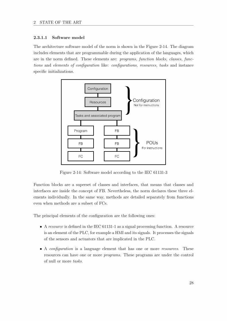
2.3.1.1 Software model . . . . . . . . . . . . . . . . . . . . . . . 29
2.3.1.2 Communication model . . . . . . . . . . . . . . . . . . . 30
2.3.1.3 Programming model . . . . . . . . . . . . . . . . . . . . 31
2.3.2 CoDeSys . . . . . . . . . . . . . . . . . . . . . . . . . . . . . . . . 32
2.3.3 Siemens TIA Portal . . . . . . . . . . . . . . . . . . . . . . . . . . 32
2.3.4 TIA Portal and CoDeSys small comparative . . . . . . . . . . . . 33
2.4 Model Based System Engineering . . . . . . . . . . . . . . . . . . . . . . 36
2.4.1 A brief history of Model Based System Engineering . . . . . . . . 36
2.4.2 Composition of MBSE . . . . . . . . . . . . . . . . . . . . . . . . 37
2.4.3 SysML . . . . . . . . . . . . . . . . . . . . . . . . . . . . . . . . . 39
3 Analysis and translation rules 40
3.1 Data type . . . . . . . . . . . . . . . . . . . . . . . . . . . . . . . . . . . 40
3.1.1 User Data Types . . . . . . . . . . . . . . . . . . . . . . . . . . . 40
3.1.1.1 UDTs in CoDeSys . . . . . . . . . . . . . . . . . . . . . 40
6
3.1.1.2 Siemens transference of UDTs . . . . . . . . . . . . . . . 41
3.1.2 Variable sections . . . . . . . . . . . . . . . . . . . . . . . . . . . 41
3.1.2.1 Variable sections in CoDeSys . . . . . . . . . . . . . . . 41
3.1.2.2 Siemens transference of variable sections . . . . . . . . . 42
3.2 Configuration . . . . . . . . . . . . . . . . . . . . . . . . . . . . . . . . . 43
3.2.1 Tasks . . . . . . . . . . . . . . . . . . . . . . . . . . . . . . . . . . 44
3.2.1.1 Tasks in CoDeSys . . . . . . . . . . . . . . . . . . . . . 44
3.2.1.2 Siemens transference of Tasks . . . . . . . . . . . . . . . 44
3.3 Program organisation unit (POU) . . . . . . . . . . . . . . . . . . . . . . 45
3.3.1 Program . . . . . . . . . . . . . . . . . . . . . . . . . . . . . . . . 45
3.3.1.1 Programs in CoDeSys . . . . . . . . . . . . . . . . . . . 46
3.3.1.2 Siemens transference of Programs . . . . . . . . . . . . . 46
3.3.2 Function blocks . . . . . . . . . . . . . . . . . . . . . . . . . . . . 48
3.3.2.1 Function blocks in CoDeSys . . . . . . . . . . . . . . . . 48
3.3.2.2 Siemens transference of function blocks . . . . . . . . . . 49
3.3.3 Classes . . . . . . . . . . . . . . . . . . . . . . . . . . . . . . . . . 50
3.3.3.1 Classes in CoDeSys . . . . . . . . . . . . . . . . . . . . . 51
3.3.3.2 Siemens transference of Classes . . . . . . . . . . . . . . 52
3.3.4 Methods of a class . . . . . . . . . . . . . . . . . . . . . . . . . . 52
3.3.4.1 Methods in CoDeSys . . . . . . . . . . . . . . . . . . . . 53
3.3.4.2 Siemens transference of methods . . . . . . . . . . . . . 53
3.3.5 Interfaces . . . . . . . . . . . . . . . . . . . . . . . . . . . . . . . 55
3.3.5.1 Interfaces in CoDeSys . . . . . . . . . . . . . . . . . . . 56
3.3.5.2 Siemens transference of Interfaces . . . . . . . . . . . . . 57
3.3.6 Method of an interface . . . . . . . . . . . . . . . . . . . . . . . . 58
3.3.6.1 Method of an interface in CoDeSys . . . . . . . . . . . . 58
3.3.6.2 Siemens transference of methods of an interface . . . . . 59
3.3.7 Properties . . . . . . . . . . . . . . . . . . . . . . . . . . . . . . . 60
3.3.7.1 Properties in CoDeSys . . . . . . . . . . . . . . . . . . . 60
3.3.7.2 Siemens transference of properties . . . . . . . . . . . . 61
4 WIDOS application 64
4.1 Configuration elements . . . . . . . . . . . . . . . . . . . . . . . . . . . . 65
4.1.1 Configuration is CoDeSys . . . . . . . . . . . . . . . . . . . . . . 65
4.1.2 Siemens configuration . . . . . . . . . . . . . . . . . . . . . . . . 65
4.2 UDT declaration . . . . . . . . . . . . . . . . . . . . . . . . . . . . . . . 66
4.3 POU elements . . . . . . . . . . . . . . . . . . . . . . . . . . . . . . . . . 67
7

4.3.1 FB-type . . . . . . . . . . . . . . . . . . . . . . . . . . . . . . . . 67
4.3.1.1 FB-types in CoDeSys . . . . . . . . . . . . . . . . . . . 68
4.3.1.2 FB-types in TIA Portal . . . . . . . . . . . . . . . . . . 69
4.3.2 Interfaces . . . . . . . . . . . . . . . . . . . . . . . . . . . . . . . 69
4.3.2.1 Interfaces in CoDeSys . . . . . . . . . . . . . . . . . . . 69
4.3.2.2 Interfaces in TIA Portal . . . . . . . . . . . . . . . . . . 71
4.3.3 Methods of a FB-types . . . . . . . . . . . . . . . . . . . . . . . . 71
4.3.3.1 Methods of FB-types in CoDeSys . . . . . . . . . . . . . 71
4.3.3.2 Methods of FB-types in TIA Portal . . . . . . . . . . . . 72
4.3.4 Methods and properties of Interfaces . . . . . . . . . . . . . . . . 73
4.3.4.1 Methods and properties of an interface in CoDeSys . . . 73
4.3.4.2 Methods and properties of an interface in TIA Portal . . 74
4.4 Code . . . . . . . . . . . . . . . . . . . . . . . . . . . . . . . . . . . . . . 75
5 Evaluation of the project 76
5.1 Results and observations . . . . . . . . . . . . . . . . . . . . . . . . . . . 76
5.1.1 Result of configuration translation . . . . . . . . . . . . . . . . . . 76
5.1.2 Result of Program translation . . . . . . . . . . . . . . . . . . . . 76
5.1.3 Result of FB translation . . . . . . . . . . . . . . . . . . . . . . . 77
5.1.4 Result of functions . . . . . . . . . . . . . . . . . . . . . . . . . . 77
5.2 Results and evaluation of the WI-CNC application . . . . . . . . . . . . 78
5.3 Summary . . . . . . . . . . . . . . . . . . . . . . . . . . . . . . . . . . . 79
6 Future prospects 80
Appendices 82
A Translation rules 82
A.1 Data type . . . . . . . . . . . . . . . . . . . . . . . . . . . . . . . . . . . 82
A.1.1 UDT . . . . . . . . . . . . . . . . . . . . . . . . . . . . . . . . . . 82
A.1.1.1 Problem . . . . . . . . . . . . . . . . . . . . . . . . . . . 82
A.1.1.2 Translation rule . . . . . . . . . . . . . . . . . . . . . . . 82
A.1.1.3 Example . . . . . . . . . . . . . . . . . . . . . . . . . . . 82
A.1.2 VAR section . . . . . . . . . . . . . . . . . . . . . . . . . . . . . . 82
A.1.2.1 Problem . . . . . . . . . . . . . . . . . . . . . . . . . . . 82
A.1.2.2 Translation rule . . . . . . . . . . . . . . . . . . . . . . . 82
A.1.2.3 Example . . . . . . . . . . . . . . . . . . . . . . . . . . . 83
A.1.3 Global variables . . . . . . . . . . . . . . . . . . . . . . . . . . . . 83
8
A.1.3.1 Problem . . . . . . . . . . . . . . . . . . . . . . . . . . . 83
A.1.3.2 Translation rule . . . . . . . . . . . . . . . . . . . . . . . 83
A.1.3.3 Example . . . . . . . . . . . . . . . . . . . . . . . . . . . 83
A.2 Configuration . . . . . . . . . . . . . . . . . . . . . . . . . . . . . . . . . 84
A.2.1 Tasks . . . . . . . . . . . . . . . . . . . . . . . . . . . . . . . . . . 84
A.2.1.1 Problem . . . . . . . . . . . . . . . . . . . . . . . . . . . 84
A.2.1.2 Transfer rule . . . . . . . . . . . . . . . . . . . . . . . . 84
A.2.1.3 Example . . . . . . . . . . . . . . . . . . . . . . . . . . . 84
A.3 POUs . . . . . . . . . . . . . . . . . . . . . . . . . . . . . . . . . . . . . 85
A.3.1 Program . . . . . . . . . . . . . . . . . . . . . . . . . . . . . . . . 85
A.3.1.1 Problem . . . . . . . . . . . . . . . . . . . . . . . . . . . 85
A.3.1.2 Transfer rule . . . . . . . . . . . . . . . . . . . . . . . . 85
A.3.1.3 Example . . . . . . . . . . . . . . . . . . . . . . . . . . . 85
A.3.2 FB-type . . . . . . . . . . . . . . . . . . . . . . . . . . . . . . . . 85
A.3.2.1 Problem . . . . . . . . . . . . . . . . . . . . . . . . . . . 85
A.3.2.2 Transfer rule . . . . . . . . . . . . . . . . . . . . . . . . 85
A.3.2.3 Example . . . . . . . . . . . . . . . . . . . . . . . . . . . 85
A.3.3 FB-instance . . . . . . . . . . . . . . . . . . . . . . . . . . . . . . 86
A.3.3.1 Problem . . . . . . . . . . . . . . . . . . . . . . . . . . . 86
A.3.3.2 Transfer rule . . . . . . . . . . . . . . . . . . . . . . . . 86
A.3.3.3 Example . . . . . . . . . . . . . . . . . . . . . . . . . . . 86
A.3.4 Classes . . . . . . . . . . . . . . . . . . . . . . . . . . . . . . . . . 86
A.3.4.1 Problem . . . . . . . . . . . . . . . . . . . . . . . . . . . 86
A.3.4.2 Transfer rule . . . . . . . . . . . . . . . . . . . . . . . . 86
A.3.5 Methods of a FB . . . . . . . . . . . . . . . . . . . . . . . . . . . 87
A.3.5.1 Problem . . . . . . . . . . . . . . . . . . . . . . . . . . . 87
A.3.5.2 Transfer rule . . . . . . . . . . . . . . . . . . . . . . . . 87
A.3.5.3 Example . . . . . . . . . . . . . . . . . . . . . . . . . . . 87
A.3.6 Interfaces . . . . . . . . . . . . . . . . . . . . . . . . . . . . . . . 88
A.3.6.1 Problem . . . . . . . . . . . . . . . . . . . . . . . . . . . 88
A.3.6.2 Transfer rules . . . . . . . . . . . . . . . . . . . . . . . . 88
A.3.6.3 Example . . . . . . . . . . . . . . . . . . . . . . . . . . . 88
A.3.7 Methods of an interface . . . . . . . . . . . . . . . . . . . . . . . 88
A.3.7.1 Problem . . . . . . . . . . . . . . . . . . . . . . . . . . . 88
A.3.7.2 Transfer rule . . . . . . . . . . . . . . . . . . . . . . . . 88
A.3.7.3 Example . . . . . . . . . . . . . . . . . . . . . . . . . . . 89
A.3.8 Property . . . . . . . . . . . . . . . . . . . . . . . . . . . . . . . . 90
9

A.3.8.1 Problem . . . . . . . . . . . . . . . . . . . . . . . . . . . 90
A.3.8.2 Transfer rule . . . . . . . . . . . . . . . . . . . . . . . . 90
A.3.8.3 Example . . . . . . . . . . . . . . . . . . . . . . . . . . . 90
10
List of Figures
2-1 Operation principle of the WI-CNC machine . . . . . . . . . . . . . . . . 18
2-2 The composition of the WI-CNC machine [WID12] . . . . . . . . . . . . 19
2-3 Hydraulic control unit [WID15b] . . . . . . . . . . . . . . . . . . . . . . 20
2-4 Planner [WID15b] . . . . . . . . . . . . . . . . . . . . . . . . . . . . . . . 20
2-5 Heating element [WID15b] . . . . . . . . . . . . . . . . . . . . . . . . . . 20
2-6 Base machine [WID15b] . . . . . . . . . . . . . . . . . . . . . . . . . . . 21
2-7 Panel PC Smart 9 . . . . . . . . . . . . . . . . . . . . . . . . . . . . . . . 21
2-8 CAN bus connection of the WI-CNC . . . . . . . . . . . . . . . . . . . . 23
2-9 Physical description of the S7-1200 PLC [Sie16] . . . . . . . . . . . . . . 24
2-10 SB 1221 DI 4x5 200 kHz . . . . . . . . . . . . . . . . . . . . . . . . . . . 25
2-11 HMI KTP 700 . . . . . . . . . . . . . . . . . . . . . . . . . . . . . . . . . 25
2-12 Composition of the SIMATIC ET 200SP . . . . . . . . . . . . . . . . . . 26
2-13 PROFINET module ET 200SP breakout [AG17] . . . . . . . . . . . . . . 27
2-14 Software model according to the IEC 61131-3 . . . . . . . . . . . . . . . 29
2-15 Communication model [CEN13] . . . . . . . . . . . . . . . . . . . . . . . 31
2-16 TIA Portal - Working area . . . . . . . . . . . . . . . . . . . . . . . . . . 34
2-17 CoDeSys - Working area . . . . . . . . . . . . . . . . . . . . . . . . . . . 35
2-18 SysML artifact hierarchy and relationship to UML. [DM13] . . . . . . . . 37
2-19 Example Block ‘Anwarme’ [Glu16] . . . . . . . . . . . . . . . . . . . . . 38
2-20 Example of Interface ‘IFeldbus’ [Glu16] . . . . . . . . . . . . . . . . . . . 38
2-21 Example showing the relationships lines [Glu16] . . . . . . . . . . . . . . 39
3-1 UDT declarations in Siemens . . . . . . . . . . . . . . . . . . . . . . . . 41
3-2 Siemens configuration . . . . . . . . . . . . . . . . . . . . . . . . . . . . . 43
3-3 Cyclic task in CoDeSys . . . . . . . . . . . . . . . . . . . . . . . . . . . . 44
3-4 Cyclic task in TIA Portal with an organization block . . . . . . . . . . . 44
3-5 How to make a assign a program to a task in TIA Portal . . . . . . . . . 46
3-6 Modified software model . . . . . . . . . . . . . . . . . . . . . . . . . . . 47
3-7 Steps to create a new FB-type in TIA Portal . . . . . . . . . . . . . . . . 49
3-8 Steps to instantiate a FB-type . . . . . . . . . . . . . . . . . . . . . . . . 50
3-9 Creation of new instances in TIA Portal . . . . . . . . . . . . . . . . . . 50
3-10 Relationship between FB and classes . . . . . . . . . . . . . . . . . . . . 51
3-11 Example of classes in TIA Portal . . . . . . . . . . . . . . . . . . . . . . 52
3-12 Return-value-type of a Method (FB) in TIA Portal . . . . . . . . . . . . 54
3-13 Steps to create a table of constants . . . . . . . . . . . . . . . . . . . . . 54
11
3-14 How to add methods and properties to an interface in CoDeSys . . . . . 56
3-15 FB-WikaA10 and it methods . . . . . . . . . . . . . . . . . . . . . . . . . 58
3-16 How to add properties in CoDeSys . . . . . . . . . . . . . . . . . . . . . 60
3-17 Not-implemented vs implemented property . . . . . . . . . . . . . . . . . 61
4-1 CoDeSys configuration . . . . . . . . . . . . . . . . . . . . . . . . . . . . 65
4-2 Siemens hardware configuration . . . . . . . . . . . . . . . . . . . . . . . 65
4-3 Basic blocks to start an OOP program in TIA Portal . . . . . . . . . . . 66
4-4 UDTs represented in CoDeSys and TIA Portal . . . . . . . . . . . . . . . 67
4-5 Axis classes in CoDeSys . . . . . . . . . . . . . . . . . . . . . . . . . . . 68
4-6 POUs declared after the classes declaration . . . . . . . . . . . . . . . . . 69
4-7 Elements of the FB Ppd11ACan . . . . . . . . . . . . . . . . . . . . . . . 70
4-8 Elements of the interfaces IFehlerAuslesbar and IDruckregler . . . . . . . 70
4-9 Interfaces IFehlerAuslesbar and IDruckregler . . . . . . . . . . . . . . . . 71
4-10 Structure of FB WiCnc . . . . . . . . . . . . . . . . . . . . . . . . . . . . 74
12

List of Tables
1 Siemens corresponding programming languages according to the norm
IEC 61131-3 . . . . . . . . . . . . . . . . . . . . . . . . . . . . . . . . . . 33
2 Variable sections supported by the norm IEC 61131-3 . . . . . . . . . . . 42
3 POU and its variable types available in TIA Portal . . . . . . . . . . . . 43
4 Comparative of classes between IT-OOP and PLC-OOP . . . . . . . . . 51
5 Axis classes and descriptions . . . . . . . . . . . . . . . . . . . . . . . . . 68
6 Summary of the project . . . . . . . . . . . . . . . . . . . . . . . . . . . 79
13
List of Abbreviations
CAN Controlled Area Network
CNC Computer Numeric Control
CoDeSys Controller Development System
FB Function Block
FBD Function block diagram
FC Function
HMI Human Machine Interface
HSC High Speed Counters
IEC International Electrotechnical Commission
LD Ladder diagram
MBSE Model-based Systems Engineering
OB Organization Block
OOP Object Oriented Programming
PLC Programmable Logic Controller
POU Program Organization Unit
PRG Program (In CoDeSys)
PROFINET Process Field Network
SB Signal Board
SCL Structured Control Language
ST Structured Text
STL Statement List
SysML System Modelling Language
TIA Portal Totally Integrated Automation Portal
UDT User Data Types
14
1 INTRODUCTION
1 Introduction
After the industrial revolution, the amount of factories or manufacturing plants have
been rapidly increasing. With this, the development in technology and machinery has
also been promptly rising.
Modern factories, have automated systems to manufacture di↵erent products. In order
to make a new system, it is important to make an analysis and design. To achieve this,
the Model Based System Engineering (MBSE) was created. MBSE is an approach to
realising successful systems. These models can be designed with SysML, a graphical
modelling language for systems development.
Today, Programmable Logic Controllers (PLC) are used to reproduce system models of
many factories. PLCs are able to control automated system in real time, for example
production lines of a car assembly.
Nowadays, there are di↵erent types and brands of PLCs. Every company that has
manufacturing plants has its own PLC preferences. Consequently, the International
Electrotechnical Commission (IEC) created the norm IEC 61131. The object of the
norm is the regularizations of the PLCs in every possible aspects like programming,
communication, security, etc.
The third section of the norm deals with the software architecture, programming model
and programming languages. The newest version of this section is from 2013 and in-
cludes the Object Oriented Programming (OOP). The application of the norm allows to
build more complex and larger programming systems required today.
Siemens, a major PLC manufacturer, has its own software product to program their
PLCs called TIA Portal. This software applies the norm in a specific way that includes
the programming languages accepted by the norm but totally excludes the OOP, among
other things. In contrast, the company 3S completely implements the norm in its soft-
ware product after the version CoDeSys V3. This software has become now the standard
software for PLC programming also involving OOP.
15

1 INTRODUCTION
1.1 Problem statement
WIDOS, is a German company that manufactures equipment used in the construction
of ditches. The principal products that the company manufactures are plastic welding
machines.
In order to be more competitive, WIDOS develops a project to re-engineer their CNC
method. Apart of this project, there is the master thesis performed by Tilmann Glucks
in collaboration with the FH-Aachen [Glu16]. This master project consisted in two
parts:
1. Making a reverse-engineering analysis of the WIDOS WI-CNC welding machine.
Taking this analysis as a base, for a new object oriented design modelled in SysML.
2. Realising the model design with CoDeSys, a PLC programming system by using
object oriented patterns and coding strategies.
Notwithstanding, the company has clients that request equipment controlled by Siemens
PLCs. Due to this demand, there is a third step in the project:
3. Finding out translation rules to convert OOP in Structured Text (ST) language
to TIA Portal in Structured Control Language (SCL).
1.2 Objective
The aim of this master thesis is to create a method to transfer code from CoDeSys V3.5
to Siemens TIA Portal V13. During the code transfer, the qualities and information
of the original program should not be lost. The result is a strategy to convert object
oriented CoDeSys code in ST to Siemens SCL by the usage of defined translation rules.
Main scope of this rules is the adaptation of OOP to Siemens implementing the IEC
norm. To prove the functionality of the method, the program was tested in the proto-
type machine WI-CNC of the WIDOS company.
The goal of the translation rules is to reuse programming structure and code. Achieving
this, the company rises the e�ciency of manufacturing process by reducing programming
times.
16

2 STATE OF THE ART
2 State of the art
2.1 WIDOS WI-CNC
The machine WI-CNC of the company WIDOS is a trench welding machine for plastic
tubes. It is made to operate in the construction site, for example, in the construction of
pipe lines for sewage systems.
The name WI-CNC is because of the CNC (Computer Numeric Control) precision of the
machine. The welding process for plastic tubes requires of a high precision. The tubes
must be perfect aligned and without irregularities for a good welding quality.
The operation principle of the machine is shown in the Figure 2-1.
Figure 2-1: Operation principle of the WI-CNC machine
1. The first step is about placing and fastening the tubes to weld in the machine.
2. The second step is to prepare the tube’s area to be welded. Both tubes must be
precisely aligned without irregularities.
3. Third step is the warming-up of the tube’s welding area.
4. Fourth and last step is pressing both tubes to each other to join them together.
2.1.1 The WIDOS WI-CNC welding machine and their parts
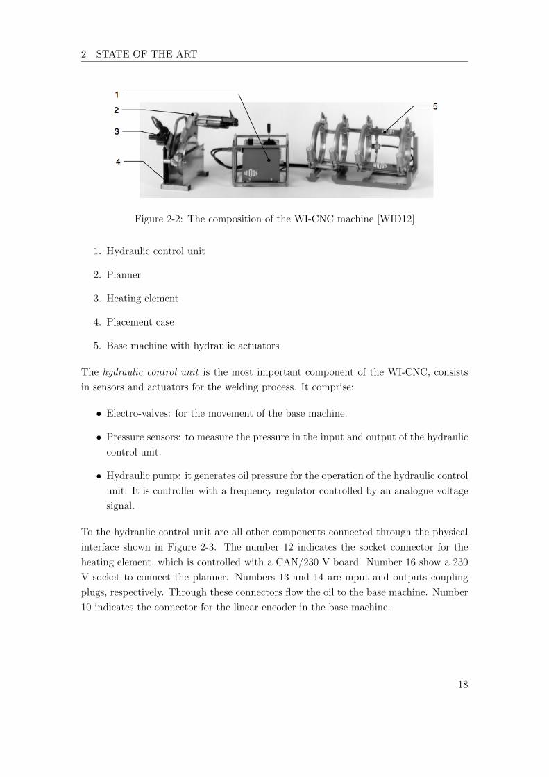
The plastic welding machine WI-CNC and its principal parts are shown in Figure 2-2.
It is important to know relevant parts of the machine for the better understanding of
the program.
17
2 STATE OF THE ART
Figure 2-2: The composition of the WI-CNC machine [WID12]
1. Hydraulic control unit
2. Planner
3. Heating element
4. Placement case
5. Base machine with hydraulic actuators
The hydraulic control unit is the most important component of the WI-CNC, consists
in sensors and actuators for the welding process. It comprise:
• Electro-valves: for the movement of the base machine.
• Pressure sensors: to measure the pressure in the input and output of the hydraulic
control unit.
• Hydraulic pump: it generates oil pressure for the operation of the hydraulic control
unit. It is controller with a frequency regulator controlled by an analogue voltage
signal.
To the hydraulic control unit are all other components connected through the physical
interface shown in Figure 2-3. The number 12 indicates the socket connector for the
heating element, which is controlled with a CAN/230 V board. Number 16 show a 230
V socket to connect the planner. Numbers 13 and 14 are input and outputs coupling
plugs, respectively. Through these connectors flow the oil to the base machine. Number
10 indicates the connector for the linear encoder in the base machine.
18

2 STATE OF THE ART
Figure 2-3: Hydraulic control unit [WID15b]
The planner is used for planing the contact surface of the tubes. That is to remove the
oxidation and align the tubes in parallel. The functionality is similar to a grinder for
shaping metal materials. This element is activated by a button in the device. Figure
2-4.
Figure 2-4: Planner [WID15b]
The heating element is for warming up the welding area of the tubes. Every material
has a di↵erent welding temperature and welding time. For this reason, it is important
to have a control over this device, a minor di↵erence in the temperature can a↵ect the
welding process. The heating element has a controller inside. The set point for the
controller is realised by an analogue input provided by the PLC. Figure 2-5.
Figure 2-5: Heating element [WID15b]
19

2 STATE OF THE ART
The base machine. This device is used to hold and move the tubes for the welding
process. One tube is fixed on the base machine and manually fastened. The another
tube is mounted in the hydraulic moving sled. Both parts can be adjusted by a manual
alignment system. Lastly a linear encoder is able to measure the exact position of the
tubes. Figure 2-6.
Figure 2-6: Base machine [WID15b]
2.1.2 WIDOS WI-CNC hardware control
The panel PC smart9 T070B of the company epis is used for automation and visualisa-
tion. The system is consists by a touch screen TFT of 7” and a micro-controller board
with an operation system (OS) WinCE 6.0 R3. The Figure 2-7 shows the panel PC.
The OS Windows Embedded CE or WicCE is the operating system of Windows tar-
geted to enterprise specific tools such as industrial controllers and consumer electronics
devices. The latest release of the OS was the WinCE 6.0 R3.
Figure 2-7: Panel PC Smart 9
20
2 STATE OF THE ART
The CPU processor ARM11 of the smart9 has the following characteristics.
Clock frequency 532 MHz
Nand-Flash 256 MB
RAM 128 MB DDR2
EEPROM 32 kByte
Slot for micro-SD Card MicroSDHC max 32 GB
2.1.3 Connection interfaces
The panel PC smart9 has di↵erent connection interfaces for the control of hardware:
• 24 V digital I/Os
• Ethernet
• RS232
• RS248
• USB
• CAN
2.1.3.1 CAN bus
The WI-CNC uses the CAN interface to control external hardware.
The Controlled Area Network (CAN) is a serial communication protocol, that is primary
used in the automotive industry. Because of its real time behaviour, it is also used in
the automation industry.
The smart9 panel PC allows up to 64 participants in the CAN bus, according to the
CANopen protocol. All the di↵erent sensor and actuators are connected to the panel
PC through the CAN interface with an specific identification.
The WI-CNC has two peripheral boards.
1. The board KF3 [WID15a] is a 230 V I/O interface for components like the heating
element, the planner and the hydraulic pump. The heating element has an extra
21
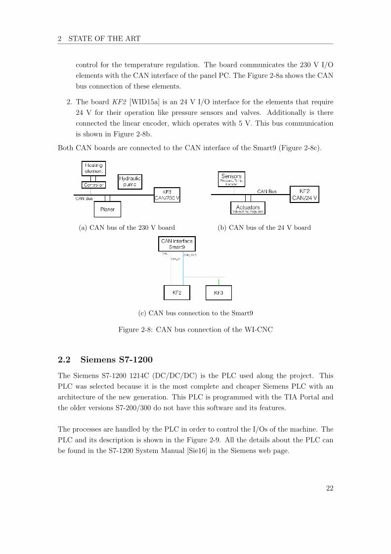
2 STATE OF THE ART
control for the temperature regulation. The board communicates the 230 V I/O
elements with the CAN interface of the panel PC. The Figure 2-8a shows the CAN
bus connection of these elements.
2. The board KF2 [WID15a] is an 24 V I/O interface for the elements that require
24 V for their operation like pressure sensors and valves. Additionally is there
connected the linear encoder, which operates with 5 V. This bus communication
is shown in Figure 2-8b.
Both CAN boards are connected to the CAN interface of the Smart9 (Figure 2-8c).
(a) CAN bus of the 230 V board (b) CAN bus of the 24 V board
(c) CAN bus connection to the Smart9
Figure 2-8: CAN bus connection of the WI-CNC
2.2 Siemens S7-1200
The Siemens S7-1200 1214C (DC/DC/DC) is the PLC used along the project. This
PLC was selected because it is the most complete and cheaper Siemens PLC with an
architecture of the new generation. This PLC is programmed with the TIA Portal and
the older versions S7-200/300 do not have this software and its features.
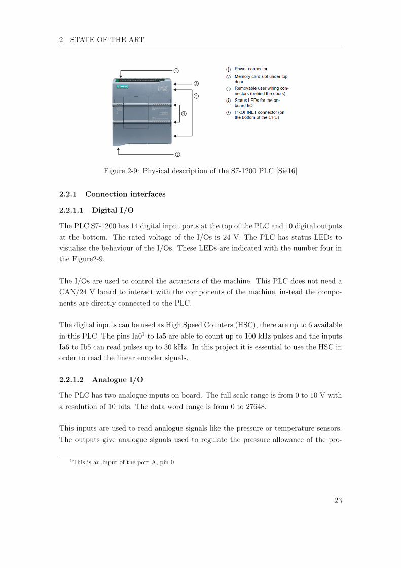
The processes are handled by the PLC in order to control the I/Os of the machine. The
PLC and its description is shown in the Figure 2-9. All the details about the PLC can
be found in the S7-1200 System Manual [Sie16] in the Siemens web page.
22
2 STATE OF THE ART
Figure 2-9: Physical description of the S7-1200 PLC [Sie16]
2.2.1 Connection interfaces
2.2.1.1 Digital I/O
The PLC S7-1200 has 14 digital input ports at the top of the PLC and 10 digital outputs
at the bottom. The rated voltage of the I/Os is 24 V. The PLC has status LEDs to
visualise the behaviour of the I/Os. These LEDs are indicated with the number four in
the Figure2-9.
The I/Os are used to control the actuators of the machine. This PLC does not need a
CAN/24 V board to interact with the components of the machine, instead the compo-
nents are directly connected to the PLC.
The digital inputs can be used as High Speed Counters (HSC), there are up to 6 available
in this PLC. The pins Ia01 to Ia5 are able to count up to 100 kHz pulses and the inputs
Ia6 to Ib5 can read pulses up to 30 kHz. In this project it is essential to use the HSC in
order to read the linear encoder signals.
2.2.1.2 Analogue I/O
The PLC has two analogue inputs on board. The full scale range is from 0 to 10 V with
a resolution of 10 bits. The data word range is from 0 to 27648.
This inputs are used to read analogue signals like the pressure or temperature sensors.
The outputs give analogue signals used to regulate the pressure allowance of the pro-
1This is an Input of the port A, pin 0
23

2 STATE OF THE ART
portional valve and the frequency regulator for the hydraulic pump.
2.2.1.3 Signal Board
The S7-1200 family provides a variety of plug-in boards for expanding the capabilities
with additional I/Os. For this project, the Signal Board (SB) 1221 was chosen, shown
in Figure 2-10. This SB has the particularity to have four digital inputs, the ones that
can be used as HSC. They are two times faster than the HSC on board being able to
read signals at a speed of 200 kHz at 5 V, which is perfect for the linear encoder used
in the WI-CNC welding machine. This linear encoder sends a 5 V pulse every 0,1 mm
of displacement.
Figure 2-10: SB 1221 DI 4x5 200 kHz
2.2.2 HMI
The Human Machine Interface (HMI) used for the project is the KTP700 PN shown in
Figure 2-11. It is a 7” touch screen with 8 additional buttons at the bottom of it. The
HMI is connected via PROFINET with the PLC and can interact with the variables of
the program loaded in the PLC program. The touch screen is programmed with TIA
Portal and it can be programmed simultaneously in the same project of the CPU.
Figure 2-11: HMI KTP 700
24

2 STATE OF THE ART
In comparison with the Smart9, this HMI is decentralised from the CPU connected via
PROFINET with the PLC.
2.2.3 I/O PROFINET Module
The SIMATIC ET 200SP is a decentralised peripheral system able to distribute I/O
processing signals to a central controller via PROFINET. The SIMATIC ET 200SP is
installed on a mounting rail and generally comprises three parts: [AG17]
1. An interface module, which communicates with all the controllers that behave
according to the PROFINET standard IEC 61158,
2. Up to 64 I/O modules, which are plugged into passive base units in any combina-
tion
3. A server module, which completes the structure of the SIMATIC ET 200SP.
Figure 2-12: Composition of the SIMATIC ET 200SP
The configuration for the project includes one SIMATIC ET 200 SP with I/O modules.
Two of this modules are very important for the development of the project, which are
analogue modules for the processing signals of sensors and actuators.
25

2 STATE OF THE ART
The first module is an analogue output module AQ 4xU/I ST. It has four outputs and
can be configured as follow:
• Current output
– ±20 mA, resolution 16 bits including sign
– 0 to 20 mA, resolution 15 bits
– 4 to 20 mA, resolution 14 bits
• Voltage output
– ± 10 V, resolution 16 bits including sign
– ± 5 V, resolution 15 bits including sign
– 0 to 10 V, resolution 15 bits
– 1 to 5 V, resolution 13 bits
The second is the analogue input module AI 8xRTD/TC 2-wire HF specially selected
for the analogue signals of the machine like the pressure and temperature sensors. This
module is made by Siemens specially for industrial sensors and has the following speci-
fications:
• Resolution: Up to 16 bits including sign
• Voltage measurement (perfect for the pressure sensors)
• Resistor measurement
• Thermal resistor (RTD)
• Thermocouple (TC)
Every module can be easily mounted and dismounted as seen in the Figure 2-13.
Figure 2-13: PROFINET module ET 200SP breakout [AG17]
26
2 STATE OF THE ART
2.3 PLC Software
2.3.1 Normative IEC 61131-3
The normative IEC 61131-3 of the International Electrotechnical Commission (IEC) is
a specification for PLC programming, not as a rigid set of rules. PLC manufacturers
choose if they want to conform the standard or not. [JT10]
The IEC 61131-3 recognises five programming languages in the latest version of 2013: two
graphical, two textual and one graphical-textual PLC programming languages: [CEN13]
• Ladder diagram (LD), graphical
• Function block diagram (FBD), graphical
• Structured text (ST), textual
• Instruction List (IL), textual
• Sequential Function Chart (SFC), graphical-textual
The norm not only describes the PLC programming languages themselves, but also of-
fers comprehensive concepts and guidelines for creating PLC projects.
The latest actualization of the norm includes the concept of OOP. That means that new
elements of OOP are comprehended like: classes, interfaces and methods. The norm
details all this elements and proposes rules to use them. For example, how to declare a
new element, how and when can the element be called, what kind of variables can have
the element, etc.
The norm proposes a list of configuration elements, POUs, section variables, data types
and variable names that a PLC system project should comply with, in order to follow
the standard. The norm also details the declaration and use of these elements.
After the introduction and the proposed programming languages, the norm begins to
detail how a PLC system should be done. The norm defines an architecture model
composed of three parts.
1. Software model
2. Communication model
3. Programming model
27
2 STATE OF THE ART
2.3.1.1 Software model
The architecture software model of the norm is shown in the Figure 2-14. The diagram
includes elements that are programmable during the application of the languages, which
are in the norm defined. These elements are: programs, function blocks, classes, func-
tions and elements of configuration like: configurations, resources, tasks and instance
specific initializations.
Figure 2-14: Software model according to the IEC 61131-3
Function blocks are a superset of classes and interfaces, that means that classes and
interfaces are inside the concept of FB. Nevertheless, the norm declares these three el-
ements individually. In the same way, methods are detailed separately from functions
even when methods are a subset of FCs.
The principal elements of the configuration are the following ones:
• A resource is defined in the IEC 61131-1 as a signal processing function. A resource
is an element of the PLC, for example a HMI and its signals. It processes the signals
of the sensors and actuators that are implicated in the PLC.
• A configuration is a language element that has one or more resources. These
resources can have one or more programs. These programs are under the control
of null or more tasks.
28
2 STATE OF THE ART
• A program can have null or more instances of function blocks or any other language
elements that in this norm are mentioned.
• A task has the ability to activate programs or instances of FB e.g. cyclic activities.
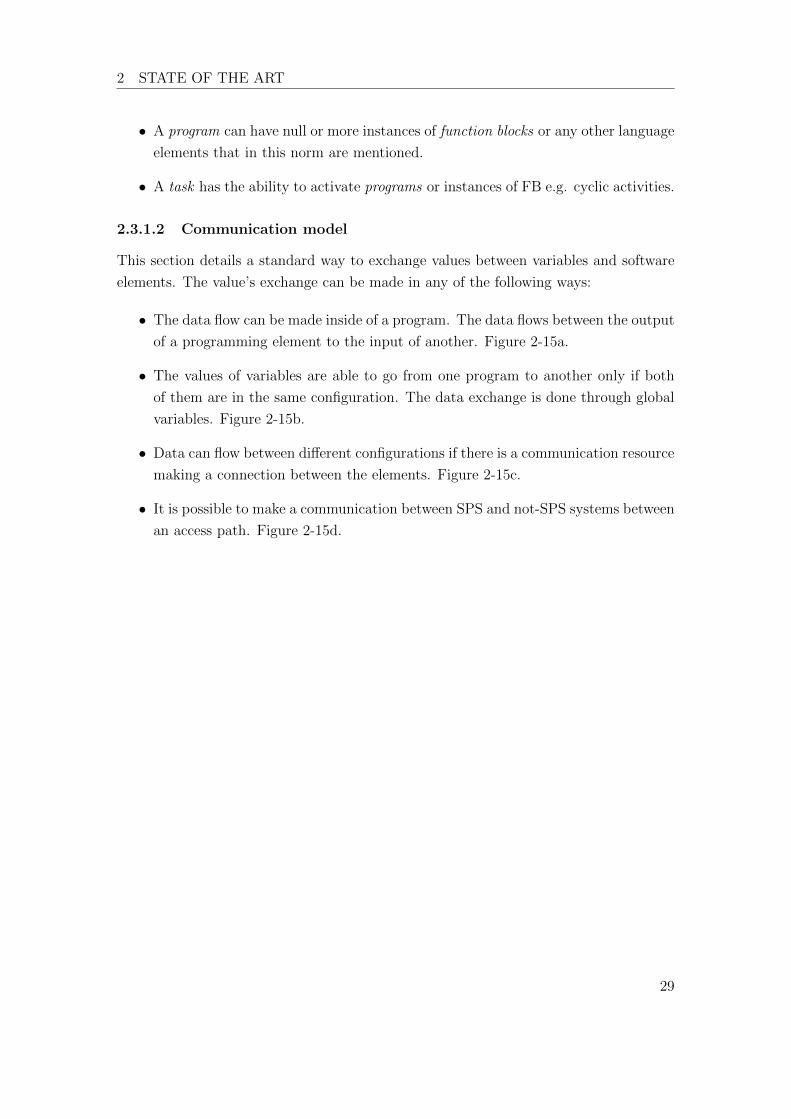
2.3.1.2 Communication model
This section details a standard way to exchange values between variables and software
elements. The value’s exchange can be made in any of the following ways:
• The data flow can be made inside of a program. The data flows between the output
of a programming element to the input of another. Figure 2-15a.
• The values of variables are able to go from one program to another only if both
of them are in the same configuration. The data exchange is done through global
variables. Figure 2-15b.
• Data can flow between di↵erent configurations if there is a communication resource
making a connection between the elements. Figure 2-15c.
• It is possible to make a communication between SPS and not-SPS systems between
an access path. Figure 2-15d.
29

2 STATE OF THE ART
(a) Data flow between two programs (b) Communication through global variables
(c) Data flow through a communication re-
source (d) Communication through access path
Figure 2-15: Communication model [CEN13]
2.3.1.3 Programming model
The programming model are the rules to call and use POUs in the for the programming
structure.
1. Programs must be declared. Inside them, standard or UDT data, functions, FB
and classes can be used.
2. A program can be performed in di↵erent configurations. In it, elements can be
used like global variables, resources, tasks and access paths.
3. Function blocks-type can be declared. Inside them, standard or UDT data, func-
tions or other function blocks can be used. In addition, object oriented FB and
classes must be defined in order to use methods and interfaces.
4. Functions can be declared. Inside them, standard or UDT (user defined type)
data, standard or user defined functions can be used.
5. Data types must be declared.
30
2 STATE OF THE ART
2.3.2 CoDeSys
CoDeSys is a software developed by the German company 3S-Smart Software Solutions
and is a global established system platform for industrial applications. From the third
version, CoDeSys implements the Norm IEC 61131-3:2013 even including OOP.
CoDeSys is a complete, integrated development environment (IDE) able to support the
most common industrial CPU architectures. It can be ported to almost all operating sys-
tems or to devices without operating system. The integrated CAN/CANopen-support
provides a genuine added value for embedded applications [Sol17].
Due to the before mentioned advantages, CoDeSys was chosen for the development of
the first part of the project. A framework application was built in CoDeSys based on
the design made in SysML. With this, the second part of the project was carried out.
From the listed programming languages in the norm, structured text (ST) was chosen
for the project. ST is the standard language for PLC programming systems. In contrast
with IL, ST o↵ers more structured possibilities being better for complex programming
systems.
2.3.3 Siemens TIA Portal
The Totally Integrated Automation Portal v13 (TIA Portal) is the software product of
Siemens to program their PLCs. However, TIA Portal is not as flexible as CoDeSys and
it cannot build embedded systems.
Siemens documents all the parts of the norm that TIA Portal fulfils. Most of them
correspond to the old version of 2003 and does not include the OOP concepts of the
latest version. This information can be downloaded from the Siemens web page [Sie13].
TIA Portal includes all programming languages of the norm in its own version. The
Table 1 shows a comparison between the programming languages of Siemens and their
corresponding language of the norm.
31

2 STATE OF THE ART
Siemens Norm IEC 61131-3
Instruction List AWL/STL AWL/IL
Ladder Logic KOP/LAD KOP/LD
Function Block Diagram FUP/FBD FUP/FBD
Structured Control Language SCL ST
S7-GRAPG AS/SFC
Table 1: Siemens corresponding programming languages according to the norm IEC
61131-3
2.3.4 TIA Portal and CoDeSys small comparative
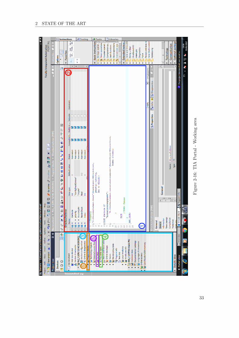
This subsection shows a comparative of both software systems. Not a syntax or pro-
gramming comparative, but a parallel visualisation of the working areas.
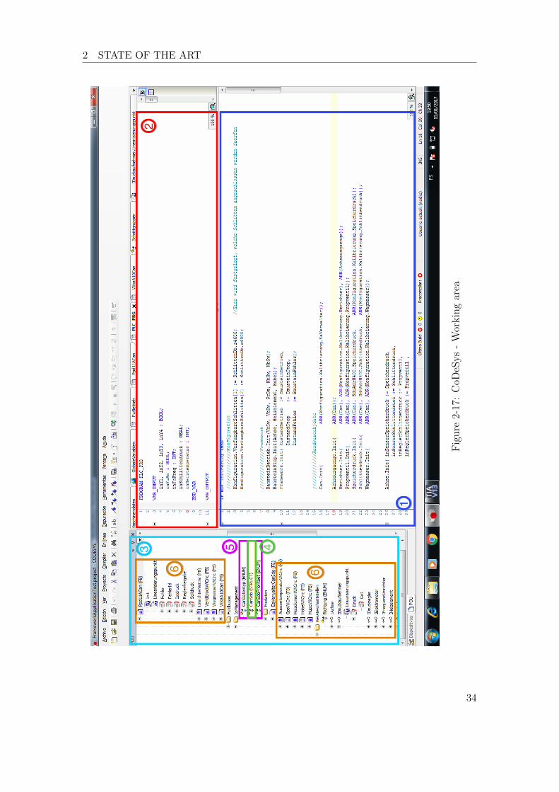
The Figure 2-16 shows the working area of TIA Portal and the Figure 2-17 the one for
CoDeSys. Nevertheless, they both have similarities as well and are listed here.
1. Work area or body: this is the area for the code. Here are the instructions
written and the functions are called.
2. Declaration area: here is where the variables of the current POU in the working
area are declared. Free written in CoDeSys and in blank spaces to fill in Siemens.
3. Project tree: in this section are shown the resources, tasks, programming blocks
and all kind of POUs.
4. Number constants: These are constant lists created by the user. This constants
serve as index for the switch cases.
5. POU: here are listed all POUs like FB, FC or interfaces. Also, UDTs and global
variables.
32
2 STATE OF THE ART
Figure
2-16:TIA
Portal-Workingarea
33
2 STATE OF THE ART
Figure
2-17:CoD
eSys
-Workingarea
34

2 STATE OF THE ART
2.4 Model Based System Engineering
2.4.1 A brief history of Model Based System Engineering
Graphical modelling languages for software development have been evolving since the
beginning of the computer sciences. These types of languages are useful for visualizing
concepts. Three graphical languages are reviewed: 1) entity- relationship (E-R) dia-
grams; 2) the unified modeling language (UML); and 3) the systems modeling language
(SysML) [DM13].
These languages are listed in chronological order as follow.
1. Entity-Relationship (E-R) diagrams :The E-R diagrams are data modelling ap-
proach introduced by Chen [Che76]. E-R is a modelling notation for high level
data, it integrates the object oriented modelling.
2. Unified Modelling Language (UML): This language is the standard for software
development and can be used in systems engineering. It is a graphical language
that provides semantics and notation for object oriented problem solving.
The UML includes the use case diagram, class diagram, package diagram, sequence
diagram, and state transition diagrams.
UML includes classes. A class become object when it is instantiated and has
attributes and methods. [Hol07]
3. Systems Modelling Language (SysML): This is a graphical modelling language that
extends UML for use in model- based systems engineering (MBSE). It provides
tools for systems engineering to design systems that include hardware, software,
data, parametric, personnel, procedures, and facilities.
Figure 2-18 illustrates the types of diagrams used by SysML; there are three pri-
mary types of diagrams at the highest level of the hierarchy: behaviour, structure,
and requirements. The requirements diagram is new and not part of UML. At
the next level down, SysML makes specialized modifications to UML activity di-
agrams, and it has made significant modifications to UML class diagrams, as ex-
tended by UML composite structures, to create what are called “block diagrams”.
A completely new type of diagram called “the parametric diagram” has been in-
troduced, which shows mathematical relationships among the pieces of the system
35

2 STATE OF THE ART
being designed and more specifically combines mathematical formulas for analysis
of critical system parameters. [DM13]
Figure 2-18: SysML artifact hierarchy and relationship to UML. [DM13]
The MBSE involves the concept that a system is a “whole” consisting of interacting
parts, which was expressed by von Bertalan↵y in 1967.
2.4.2 Composition of MBSE
A MBSE is compound of block definition diagrams, which are made of two basic ele-
ments: blocks and relationships. Both of them may have more detailed syntax that can
be used to add more information about them. The Blocks describe the types of things
that exist in a system, whereas relationships describe what the relationships are between
the blocks. [HP13a]
The blocks can have features like ‘Operations’ or ‘Properties’, later explained in Chapter
3. Blocks have normally only properties, but can also contain operations. An example
is shown in the Figure 2-19.
36
2 STATE OF THE ART
Figure 2-19: Example Block ‘Anwarme’ [Glu16]
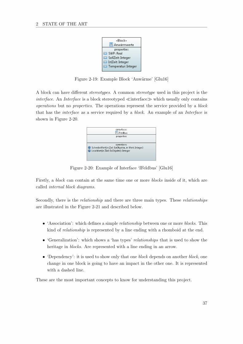
A block can have di↵erent stereotypes. A common stereotype used in this project is the
interface. An Interface is a block stereotyped ⌧interface� which usually only contains
operations but no properties. The operations represent the service provided by a block
that has the interface as a service required by a block. An example of an Interface is
shown in Figure 2-20.
Figure 2-20: Example of Interface ‘IFeldbus’ [Glu16]
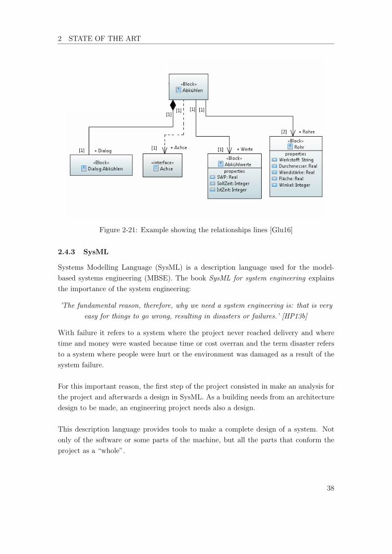
Firstly, a block can contain at the same time one or more blocks inside of it, which are
called internal block diagrams.
Secondly, there is the relationship and there are three main types. These relationships
are illustrated in the Figure 2-21 and described below.
• ‘Association’: which defines a simple relationship between one or more blocks. This
kind of relationship is represented by a line ending with a rhomboid at the end.
• ‘Generalization’: which shows a ‘has types’ relationships that is used to show the
heritage in blocks. Are represented with a line ending in an arrow.
• ‘Dependency’: it is used to show only that one block depends on another block, one
change in one block is going to have an impact in the other one. It is represented
with a dashed line.
These are the most important concepts to know for understanding this project.
37
2 STATE OF THE ART
Figure 2-21: Example showing the relationships lines [Glu16]
2.4.3 SysML
Systems Modelling Language (SysML) is a description language used for the model-
based systems engineering (MBSE). The book SysML for system engineering explains
the importance of the system engineering:
’The fundamental reason, therefore, why we need a system engineering is: that is very
easy for things to go wrong, resulting in disasters or failures.’ [HP13b]
With failure it refers to a system where the project never reached delivery and where
time and money were wasted because time or cost overran and the term disaster refers
to a system where people were hurt or the environment was damaged as a result of the
system failure.
For this important reason, the first step of the project consisted in make an analysis for
the project and afterwards a design in SysML. As a building needs from an architecture
design to be made, an engineering project needs also a design.
This description language provides tools to make a complete design of a system. Not
only of the software or some parts of the machine, but all the parts that conform the
project as a “whole”.
38

3 ANALYSIS AND TRANSLATION RULES
3 Analysis and translation rules
3.1 Data type
A data type is a classification for variables, which are used in a program. A type classi-
fies the variables according to the type of its value.
In the programming world exists di↵erent types of data. For example, integer, real,
string, etc. All qualified data types are listed in the Chapter 6 Data types of the norm
IEC 61131-3 [CEN13].
Siemens fulfils this point of the norm and supports all data types listed in it. The only
di↵erence is that in CoDeSys is possible to write the data types freely, while Siemens
has blank spaces to fill with the variable names and types.
The data types listed in the norm IEC 61131-3 are available in both programming
software.
3.1.1 User Data Types
A user data type (UDT) is a data type defined by the user. The user can name the data
type with any name. An UDT can have one or more di↵erent data types in it and even
other UDTs. An UDT can be used for the declaration of any variable in the program.
3.1.1.1 UDTs in CoDeSys
The declaration of a new UDT in CoDeSys must be between TYPE and END TYPE as
the norm declares in the section 6.4.4.
The following code is an example of UDT to describe a WIDOS machine.
Listing 3.1: UDT Machinendaten CoDeSys
1 TYPE Maschinendaten :
2 STRUCT
3 SoftwareVersion : STRING;
4 Seriennumer : STRING;
5 Schlittentyp : STRING;
6 LetzteWartung : DATE;
7 NaechsteWartung : DATE;
39

3 ANALYSIS AND TRANSLATION RULES
8 END_STRUCT
9 END_TYPE
3.1.1.2 Siemens transference of UDTs
In Siemens there is a section called PLC Data Types which is the equivalent of the UDT.
This option can be found in the project tree and can be seen in the Figure 3-1a. An
example of an UDT declaration is show in the Figure 3-1b. This kind of data types are
reachable from every POU as well.
(a) UDT declaration window (b) UDT fillable spaces
Figure 3-1: UDT declarations in Siemens
Rule: The UDTs of CoDeSys are the PLC Data types in Siemens
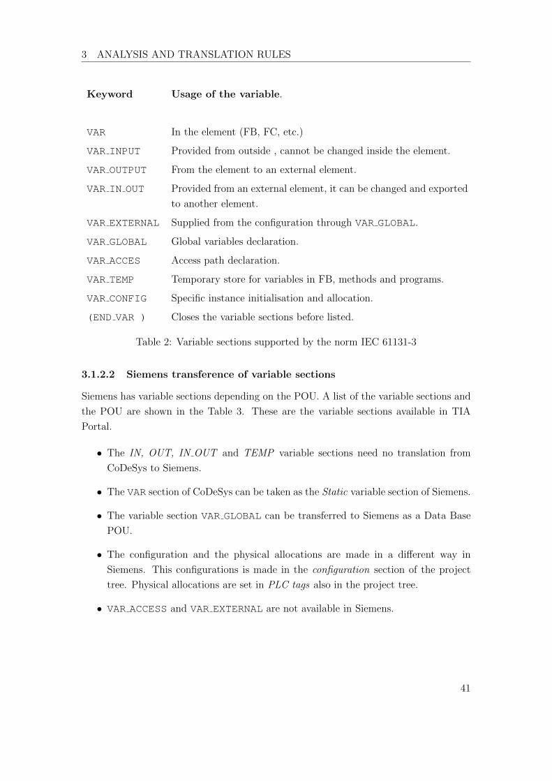
3.1.2 Variable sections
Every POU begins with the variables declaration. According to the type of POU depend
the variable sections that a POU can have.
3.1.2.1 Variable sections in CoDeSys
In CoDeSys a variable section is defined by VAR ... END VAR. The di↵erent vari-
able sections and their descriptions are listed in the norm in the section 6.5.2. The Table
2 shows the di↵erent variable sections and a short descriptions according to the norm
IEC 61131-3.
40
3 ANALYSIS AND TRANSLATION RULES
Keyword Usage of the variable.
VAR In the element (FB, FC, etc.)
VAR INPUT Provided from outside , cannot be changed inside the element.
VAR OUTPUT From the element to an external element.
VAR IN OUT Provided from an external element, it can be changed and exported
to another element.
VAR EXTERNAL Supplied from the configuration through VAR GLOBAL.
VAR GLOBAL Global variables declaration.
VAR ACCES Access path declaration.
VAR TEMP Temporary store for variables in FB, methods and programs.
VAR CONFIG Specific instance initialisation and allocation.
(END VAR ) Closes the variable sections before listed.
Table 2: Variable sections supported by the norm IEC 61131-3
3.1.2.2 Siemens transference of variable sections
Siemens has variable sections depending on the POU. A list of the variable sections and
the POU are shown in the Table 3. These are the variable sections available in TIA
Portal.
• The IN, OUT, IN OUT and TEMP variable sections need no translation from
CoDeSys to Siemens.
• The VAR section of CoDeSys can be taken as the Static variable section of Siemens.
• The variable section VAR GLOBAL can be transferred to Siemens as a Data Base
POU.
• The configuration and the physical allocations are made in a di↵erent way in
Siemens. This configurations is made in the configuration section of the project
tree. Physical allocations are set in PLC tags also in the project tree.
• VAR ACCESS and VAR EXTERNAL are not available in Siemens.
41
3 ANALYSIS AND TRANSLATION RULES
OB Input FB Input
Temp Output
Constant InOut
Static
Temp
Constant
FC Input DB Static
Output
InOut
Temp
Constant
Table 3: POU and its variable types available in TIA Portal
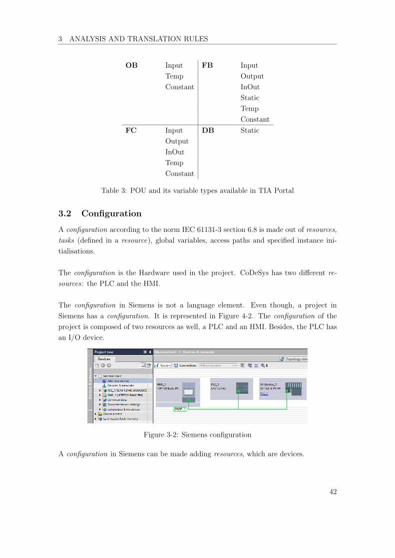
3.2 Configuration
A configuration according to the norm IEC 61131-3 section 6.8 is made out of resources,
tasks (defined in a resource), global variables, access paths and specified instance ini-
tialisations.
The configuration is the Hardware used in the project. CoDeSys has two di↵erent re-
sources : the PLC and the HMI.
The configuration in Siemens is not a language element. Even though, a project in
Siemens has a configuration. It is represented in Figure 4-2. The configuration of the
project is composed of two resources as well, a PLC and an HMI. Besides, the PLC has
an I/O device.
Figure 3-2: Siemens configuration
A configuration in Siemens can be made adding resources, which are devices.
42

3 ANALYSIS AND TRANSLATION RULES
3.2.1 Tasks
A task according to the section 6.8.2 of the norm 61131-3:2013 is defined as an execution
control element. A very common task used is the cyclic function. It makes a program
or FB execute again and again until the PLC is stopped.
3.2.1.1 Tasks in CoDeSys
An example task in CoDeSys is shown in the Figure 3-3. This task executes the program
“PLC PRG” in a cyclic way.
Figure 3-3: Cyclic task in CoDeSys
This task can execute others POUs, normally programs. It is used in this project to
execute the main program that contains all the instructions and functions of the PLC.
One or more calls can be added to this task.
3.2.1.2 Siemens transference of Tasks
In Siemens there are no tasks as a program element. But there is another element that
can make the function of a task. TIA Portal has a POU called Organization Block (OB).
This OB has the same function as a Task described in the norm. The figure 3-4 shows
how to create a new OB with the cyclic function as in CoDeSys.
Figure 3-4: Cyclic task in TIA Portal with an organization block
43
3 ANALYSIS AND TRANSLATION RULES
Rule: The cyclic tasks in CoDeSys can be taken as the organization blocks in TIA
Portal with a “Program cycle” function.
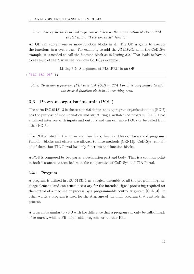
An OB can contain one or more function blocks in it. The OB is going to execute
the functions in a cyclic way. For example, to add the PLC PRG as in the CoDeSys
example, it is needed to call the function block as in Listing 3.2. That leads to have a
close result of the task in the previous CoDeSys example.
Listing 3.2: Assignment of PLC PRG in an OB
1 "PLC_PRG_DB"();
Rule: To assign a program (FB) to a task (OB) in TIA Portal is only needed to add
the desired function block in the working area.
3.3 Program organisation unit (POU)
The norm IEC 61131-3 in the section 6.6 defines that a program organisation unit (POU)
has the purpose of modularisation and structuring a well-defined program. A POU has
a defined interface with inputs and outputs and can call more POUs or be called from
other POUs.
The POUs listed in the norm are: functions, function blocks, classes and programs.
Function blocks and classes are allowed to have methods [CEN13]. CoDeSys, contain
all of them, but TIA Portal has only functions and function blocks.
A POU is composed by two parts: a declaration part and body. That is a common point
in both instances as seen before in the comparative of CoDeSys and TIA Portal.
3.3.1 Program
A program is defined in IEC 61131-1 as a logical assembly of all the programming lan-
guage elements and constructs necessary for the intended signal processing required for
the control of a machine or process by a programmable controller system [CEN04]. In
other words a program is used for the structure of the main program that controls the
process.
A program is similar to a FB with the di↵erence that a program can only be called inside
of resources, while a FB only inside programs or another FB.
44
3 ANALYSIS AND TRANSLATION RULES
3.3.1.1 Programs in CoDeSys
A program in CoDeSys must be declared between the keywords PROGRAM and END PROGRAM
in the declaration part. For example:
1 PROGRAM PLC_PRG
2
3 VAR ... END_VAR4
5 END_PROGRAM
As seen in Figure 3-3 the program is instantiated inside a task, which is inside a resource,
which is the PLC.
3.3.1.2 Siemens transference of Programs
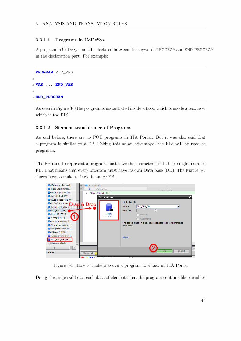
As said before, there are no POU programs in TIA Portal. But it was also said that
a program is similar to a FB. Taking this as an advantage, the FBs will be used as
programs.
The FB used to represent a program must have the characteristic to be a single-instance
FB. That means that every program must have its own Data base (DB). The Figure 3-5
shows how to make a single-instance FB.
Figure 3-5: How to make a assign a program to a task in TIA Portal
Doing this, is possible to reach data of elements that the program contains like variables
45

3 ANALYSIS AND TRANSLATION RULES
in the FB that the program contains. For example:
1 #Value := "PLC_PRG_DB".Axis.PressureSensorA.Pressure;
As the norm declares, programs must be instantiated inside a task which is an OB.
Rule: A program can be represented in TIA Portal as a single-instance FB, which is
instantiated inside an OB (task).
It is important to notice that the usage of a FB in an OB (task) is only possible with
single-instance FB. If a single-instance FB is always a program, then it is not possible
to add normal FB to a task. Therefore, the software model is limited, forcing to add a
program first and then a FB. The software model is now modified as shown in Figure
3-6.
Figure 3-6: Modified software model
46
3 ANALYSIS AND TRANSLATION RULES
3.3.2 Function blocks
A function block (FB) is a POU listed in the norm IEC 61131-3. The concept of FB is
composed by the following definitions:
• A Function block-type (FB-type) is:
– The definition of a data structure, composed by inputs, outputs and internal
variables.
– An amount of operations that will be executed when an instance of the func-
tion block-type is called.
• A Function block-instance (FB-instance):
– Is a multi-applicable function of a FB-type.
– Every instance must have a corresponding identifier (name). Besides of a
data structure of inputs, outputs and intern variables.
3.3.2.1 Function blocks in CoDeSys
A function block in CoDeSys must be declared in the declaration part by the keyword
FUNCTION BLOCK . For example:
1 FUNCTION_BLOCK WikaA10
2
3 VAR_INPUT ... END_VAR4 VAR_OUTPUT ... END_VAR5 VAR ... END_VAR6 ...
That is a Function block-type of a pressure sensor called WikaA10. That means, a
structure of a program with variables and instructions but not yet instantiated.
This FB-type can be instantiate in the following way:
1 VAR2 PressureSensorA : WikaA10;
3 END_VAR4 ...
47

3 ANALYSIS AND TRANSLATION RULES
PressureSensorA is a FB-instance of the FB-type WikaA10. This FB-instance has its
own variable values and can execute operations.
In the OOP environment, the FB-instance is the object created from the class FB-type.
In this example, PressureSensorA is an object of the class WikaA10.
3.3.2.2 Siemens transference of function blocks
A function block is an o�cial programming element in TIA Portal. It can be added in a
program, or be called from another FB. It can have single-instances and multi-instances.
The steps to create a new FB in TIA Portal are shown in Figure 3-7.
Figure 3-7: Steps to create a new FB-type in TIA Portal
A new FB has been created, but it is not yet a FB-type, that means that this FB is not
able to make instances. To transform this FB into a FB-type it is necessary to turn the
FB into a multi-instance FB. The steps to this are shown in the Figure 3-8.
Ruel: A FB-type of CoDeSys is a multi-instance FB in Siemens
48

3 ANALYSIS AND TRANSLATION RULES
Figure 3-8: Steps to instantiate a FB-type
Doing this process, the FB-type automatically creates a FB-instance, pointed in the
Figure 3-8 as Result. More instances can be created now that the FB-type exists. This
process is just as easy as in CoDeSys. Every new instance is a new variable, this variable
must be created in the variable section static and then select as data type the name of
the FB-type. An example is shown in the Figure 3-9.
Figure 3-9: Creation of new instances in TIA Portal
The variables SensorPressureA and SensorPressureB are FB-instances of the FB-type
WikaA10. In OOP terms it can be said that SensorPressureA and SensorPressureB are
objects of the class WikaA10.
Rule: the process to create a FB-instance is the same in TIA Portal and in CoDeSys.
That is, through the creation of a new variable selecting as data type the wished
FB-type. This variable must be created in the section variable “static”.
3.3.3 Classes
The norm IEC 61131-3:2003 was extended to add the concept of OOP. With this new
concept the function blocks can be defined to serve as classes.
49

3 ANALYSIS AND TRANSLATION RULES
It is important to clarify that a class has a di↵erent meaning in IT programming lan-
guages like C#, Java or UML. The Table 4 makes an explanation of these meanings.
IT programming language PLC programming languages of the norm
Class (=Type of a class) Type of a Function block or a class
Object (= instance of a class) Instance of a Function block or a class
Table 4: Comparative of classes between IT-OOP and PLC-OOP
A FB-type can be taken as a class. Both can implement interfaces and methods. Can
be said that a FB can be extended to become a class. The Figure 3-10 explains the
relationship between classes and FB.
Figure 3-10: Relationship between FB and classes
A class is used to make di↵erent objects from the same type. That makes big codes
easier to program, modify and understand.
3.3.3.1 Classes in CoDeSys
A class in CoDeSys can be declared by the keyword CLASS. But it can be a FB-type as
explained in the last chapter. If it is done with FB then the transference to Siemens is
easier.
An example of a class usage inside a FB-type is shown below.
Listing 3.3: MachineAxis Class
1 FUNCTION_BLOCK AchseWiCnc
2
50
3 ANALYSIS AND TRANSLATION RULES
3 VAR4 PressureSensorA : WikaA10;
5 PressureSensorB : WikaA10;
6 ...
7 END_VAR
This is a new class for the axis of a WIDOS machine that uses two sensors of the same
type. In this way two instances of the same type are called, each one with its own
variable values.
3.3.3.2 Siemens transference of Classes
Classes are not a programming element in the TIA Portal. Therefore, the usage of
classes in Siemens is exactly the same of a FB-type. If there is some case that a class is
used in CoDeSys, the translation to Siemens would be done as if it were a FB-type.
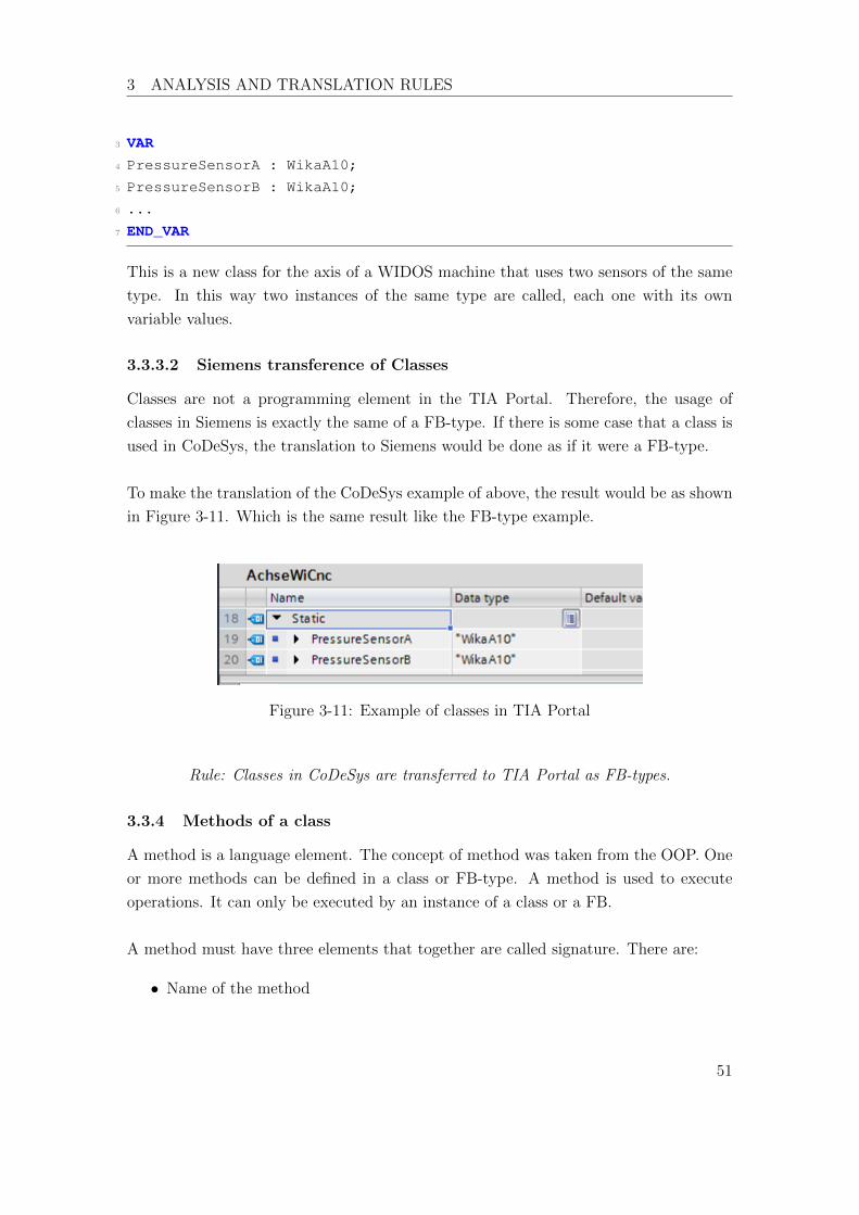
To make the translation of the CoDeSys example of above, the result would be as shown
in Figure 3-11. Which is the same result like the FB-type example.
Figure 3-11: Example of classes in TIA Portal
Rule: Classes in CoDeSys are transferred to TIA Portal as FB-types.
3.3.4 Methods of a class
A method is a language element. The concept of method was taken from the OOP. One
or more methods can be defined in a class or FB-type. A method is used to execute
operations. It can only be executed by an instance of a class or a FB.
A method must have three elements that together are called signature. There are:
• Name of the method
51

3 ANALYSIS AND TRANSLATION RULES
• Result type
• Variables declared with name and type. That means, input, output or in-out
variables.
VAR variables are always taken as temporary variables. That means they are not saved
in the PLC memory and are only available when the method is called. The values of
the variables are reset every time that the method is called.
A method contains code instructions to be executed when is called. It returns a result
value according to the input parameters and the result type.
3.3.4.1 Methods in CoDeSys
A method in CoDeSys is a language element, which can be added to any class or FB
by selecting the desired element and then add method. A method is declared by the
keyword METHOD followed by the name of the method. For example a method called
Init would be declared as follow:
1 METHOD Init
2 VAR_IN .. END_VAR3 VAR_OUT .. END_VAR4 VAR .. END_VAR
3.3.4.2 Siemens transference of methods
A method is not a programming element available in the TIA Portal. But the charac-
teristics of a method are so similar to the characteristics of a function (FC).
A signature of a method made in TIA Portal is the following:
• The name must begin with a “M.”, then the name of the class followed by a dot
and finally the name of the method.
e.g. M.WikaA10.Init
• The result type is the return value type. It can be set in the declaration part of
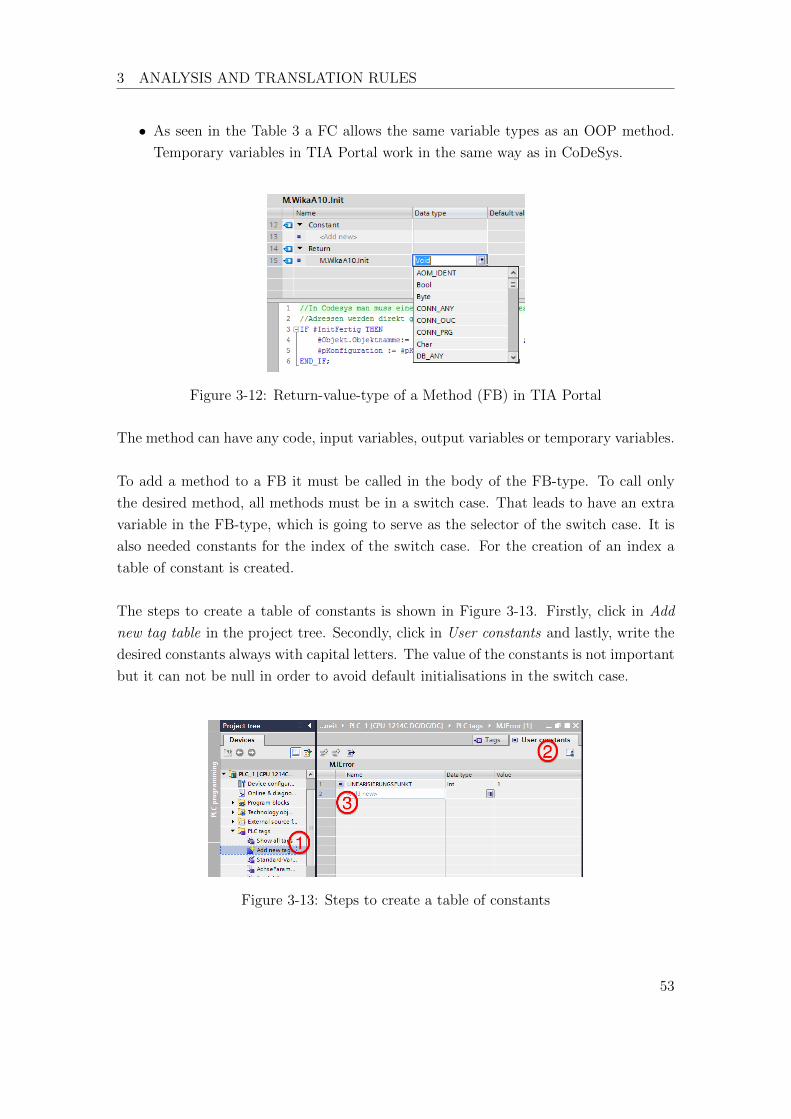
the POU as shown in the Figure 3-12.
52
3 ANALYSIS AND TRANSLATION RULES
• As seen in the Table 3 a FC allows the same variable types as an OOP method.
Temporary variables in TIA Portal work in the same way as in CoDeSys.
Figure 3-12: Return-value-type of a Method (FB) in TIA Portal
The method can have any code, input variables, output variables or temporary variables.
To add a method to a FB it must be called in the body of the FB-type. To call only
the desired method, all methods must be in a switch case. That leads to have an extra
variable in the FB-type, which is going to serve as the selector of the switch case. It is
also needed constants for the index of the switch case. For the creation of an index a
table of constant is created.
The steps to create a table of constants is shown in Figure 3-13. Firstly, click in Add
new tag table in the project tree. Secondly, click in User constants and lastly, write the
desired constants always with capital letters. The value of the constants is not important
but it can not be null in order to avoid default initialisations in the switch case.
Figure 3-13: Steps to create a table of constants
53

3 ANALYSIS AND TRANSLATION RULES
The rules to implement a method in a FB-type with TIA Portal are the following ones:
• The name must begin with the letter “M”, then the name of the FB-type that the
method belongs to and finally the name of the method. In between of every word
a dot must be written.
e.g. M.WikaA10.Linearisierungspunkt
• Methods must be added to the FB-type inside a switch case.
• The FB-type must add a new variable called “Method” of type integer. This
variable is used as the selector for the switch case.
• The inputs and outputs of the method must be declared as input and outputs in
the FB-type.
• A tag table of user constants must be created in order to serve as the index of the
switch case. (This table is important because its values can be reached from any
POU in the project)
3.3.5 Interfaces
As defined in section 6.6.6 of the norm, an interface is a language element related to
OOP. It contains prototyped methods to be implement by an object or instance. An
interface do not have instructions, which is the main di↵erence from the classes.
There are two ways to use an interfaces:
• In a class declaration:
A class implements an interface. The interface declares which methods must the
class implement .
• As variable type:
Variables that have an interface as data type are instances of the interface. That
means that the variable can use the elements of the interface like methods and
variables.
An interface can contain methods and properties. A method is an action to be imple-
mented by an instance of the interface. A property is a state of the instance. Properties
are not mentioned in the norm IEC 61131-3:2013, even though they are still methods
54

3 ANALYSIS AND TRANSLATION RULES
but with specific functions.
To give an illustration, an interface can be seen as a toolbox. The toolbox has tools,
which are the methods and properties. A method is a tool that makes an action, for
example a screwdriver or a hammer. On the other hand are the properties, these are
tools that inform a state of the instance, for example a measuring tape or a level bubble.
An interface or toolbox is useless until someone uses it, because a toolbox can not be
used by itself. When an interface is instantiated, then it is no more useless.
3.3.5.1 Interfaces in CoDeSys
An interface is a language element available in the software. To it can be added methods
and properties in an easy way as shown in Figure 3-14.
Figure 3-14: How to add methods and properties to an interface in CoDeSys
To implement an interface in a class or FB is needed to write the keyword IMPLEMENTS,
for example:
1 PROGRAM_BLOCK WikaA10Can IMPLEMENTS IDruckaufnehemer
2 VAR ... END_VAR3 ...
The name of an interface must begin with an “I” followed by the name of the interface.
Druckaufnehemer is the German name for pressure sensor. Since WikaA10 is a FB for
55

3 ANALYSIS AND TRANSLATION RULES
a pressure sensor, it can implement the interface IDruckaunehemer to add its methods.
The other usage of an interface is as a variable type. To do this in CoDeSys it is as
easy as to declare a variable. In the next example PressureSensorA is an instance of the
interface IDruckaufnehmer.
1 VAR2 PressureSensorA : IDruckaufnehmer;
3 ....
4 END_VAR
3.3.5.2 Siemens transference of Interfaces
Siemens has no POU for interfaces. But an interface is similar to a class and a class is
similar to a FB. Interfaces are transferred to Siemens as Function Blocks (interface-FB).
An interface-FB, starts its name with an “I”. This element may not have instructions
even when it has a body. An interface-FB can have one or more instances, for this reason
a FB that serves as an interface must be turned into a multi-instance FB.
The methods and properties are called in the body of the interface-FB. That leads the
interface-FB to have inputs and outputs. These input and output variables are the same
variables of the methods and properties. Besides, a variable named “Method” must be
added to select the method to be called. This is going to be detailed in the next sections.
An interface-FB calls methods and properties in its body. The interface IDruckaufnehmer
has one property and one method, therefore the interface-FB body results in the follow-
ing way:
1 //Property
2 "P.IDruckAufnehmer.Druck"(Druckobjekt:=#Druckobjekt,
3 pKonfig:=#pKonfig,
4 Get => #Druck);
5
6 //Method
7 CASE #Methode OF8 "Liniarisierungspunkt":
56

3 ANALYSIS AND TRANSLATION RULES
9 "M.IDruchaufnehmer.Liniarisierungspunkt"(RealerDruck:=#RealerDruck,
10 Index:=#Index);
11 ;
12 END_CASE;
Rule: An interface is transferred to TIA Portal as a multi-instance FB without
instructions.
3.3.6 Method of an interface
A method of an interface is in fact a prototype of a method. According to the norm, a
prototype-method has input, output and in-output variables, besides of the result type
of the method. Nevertheless, it does not have algorithm (code) or temporary variables.
That means that the method is not implemented.
3.3.6.1 Method of an interface in CoDeSys
A prototype-method is called in CoDeSys “Interface method” as seen in Figure 3-14.
The declaration of a method is with the keyword METHOD followed by the name of the
method. An interface method has only declaration part but no body. It has a body to
write code only when is implemented in a class or FB.
For example, the FBWikaA10 is a pressure sensor that implements the interface “IDruck-
aufnehemer”. The interface has a method and a property: “Linearisierungspunkt” and
“Druck” respectively. The structure of the FB is shown in Figure 3-15.
Figure 3-15: FB-WikaA10 and it methods
The prototype-method “Linearisierungspunkt” has the next configuration:
1 METHOD Linearisierungspunkt
2 VAR_INPUT3 RealerDruck : REAL;
4 Index : INT;
5 END_VAR
57

3 ANALYSIS AND TRANSLATION RULES
Since the interface is already implemented in a FB, Linearisierungspunkt is no more a
prototype-method but a method of a class. That means that it has body to write code
and allows to declare temporary variables.
The method can be called from any POU in the following way.
1 WikaA10Can.Linearisierungspunkt(RealerDruck:=RealPressure,
2 Index:=In_index)
First, the name of the FB that implements must be written followed by a dot. After
that, the name of the method to be called. And finally, between parenthesis the input
or output values must be filled. The calling of a method is the same either if it is
implemented to a FB or used as a variable type.
3.3.6.2 Siemens transference of methods of an interface
This element is not available in TIA Portal and there is no way to make a prototype-
method. A method of an interface is the same as a method of class. In other words, a
method in TIA Portal will always be implemented, that means that it will always have
code.
The rules to implement a method in an interface with TIA Portal are the following ones:
• The name must begin with the letter “M”, then the name of the interface that the
method belongs to and finally the name of the method. In between of every word
a dot must be written.
e.g. M.IDruckaufnehmer.Linearisierungspunkt
• Methods must be added to the interface inside a switch case.
• The interface must add a new variable called “Method” of type integer. This
variable is used as the selector for the switch case.
• The inputs and outputs of the method must be declared as input and outputs in
the interface-FB.
• A tag table of user constants must be created in order to serve as the index of the
switch case. (This table is important because its values can be reached from any
POU in the project)
58

3 ANALYSIS AND TRANSLATION RULES
To call a method in Siemens is in the following way:
1 #Achse(Parameter := "SPEICHERDRUCK",
2 Methode := "LESEPARAMETERREAL",
3 Wert => #outDruckSpeicher);
Where Parameter is an input value, Wert is an output value and Methode is name of
the method.
3.3.7 Properties
Properties are not declared in the IEC 61131-3 but they are methods with specific func-
tions. These can be added to an interface and afterwards to a FB.
Properties define parameters and states of a FB. A property has two di↵erent methods:
one for writing and another for reading. These methods are also called setters (to write)
and getters (to read).
A property has a result value, but may not have code, not even in the implementation.
The methods set and get are the ones that may have code but only in the implementation.
3.3.7.1 Properties in CoDeSys
A property is also a programming element available in CoDeSys. To add a property inside
an interface it is necessary to click over the interface and add property. It automatically
add the methods set and get. This process is shown in Figure 3-16.
Figure 3-16: How to add properties in CoDeSys
A property has a result value just as a method. This value is set or gotten according to
59

3 ANALYSIS AND TRANSLATION RULES
the function. For example, the interface IDruckaufnehmer has a property called Druck 2.
The property informs the state of a sensor. The PLC READS the signal of the sensor,
which means a get method is used. The property may be real because the pressure value
can have decimal point.
This interface is implemented to the FB WikaA10Can. The FB automatically imports
the property. This example is shown in the Figure 3-17. In the upper part is the inter-
face that only shows the name and data type of the property. The lower part shows the
get method implemented in the FB WikaA10Can.
Figure 3-17: Not-implemented vs implemented property
The way to get the value of a property is the following.
1 Pressure := SensorSchlittendruck.Druck;
Where SensorSchlittendruck is a variable of type IDruckAufnehmer, that means, Sen-
sorSchilttendruck is an instance of the interface.
3.3.7.2 Siemens transference of properties
A property is not an element in TIA Portal. Since a property is a function, properties
are going to be transferred to TIA Portal as property-FC. In contrast with the methods,
a property does not make actions, but only informs states. Therefore, it is not neces-
sary to make a switch case, properties are only going to be called inside the interface-FB.
To add the set and get methods, a property is going to have an input value called set
and/or an output value called get. The value of the property is saved in an in/output
2German word for Pressure
60
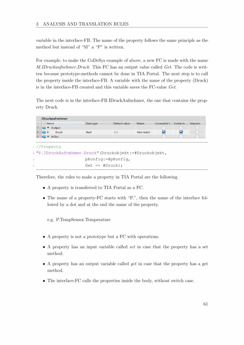
3 ANALYSIS AND TRANSLATION RULES
variable in the interface-FB. The name of the property follows the same principle as the
method but instead of “M” a “P” is written.
For example, to make the CoDeSys example of above, a new FC is made with the name
M.IDruckaufnehmer.Druck. This FC has an output value called Get. The code is writ-
ten because prototype-methods cannot be done in TIA Portal. The next step is to call
the property inside the interface-FB. A variable with the name of the property (Druck)
is in the interface-FB created and this variable saves the FC-value Get.
The next code is in the interface-FB IDruckAufnehmer, the one that contains the prop-
erty Druck.
1 //Property
2 "P.IDruckAufnehmer.Druck"(Druckobjekt:=#Druckobjekt,
3 pKonfig:=#pKonfig,
4 Get => #Druck);
Therefore, the rules to make a property in TIA Portal are the following.
• A property is transferred to TIA Portal as a FC.
• The name of a property-FC starts with “P.”, then the name of the interface fol-
lowed by a dot and at the end the name of the property.
e.g. P.TempSensor.Temperature
• A property is not a prototype but a FC with operations.
• A property has an input variable called set in case that the property has a set
method.
• A property has an output variable called get in case that the property has a get
method.
• The interface-FC calls the properties inside the body, without switch case.
61
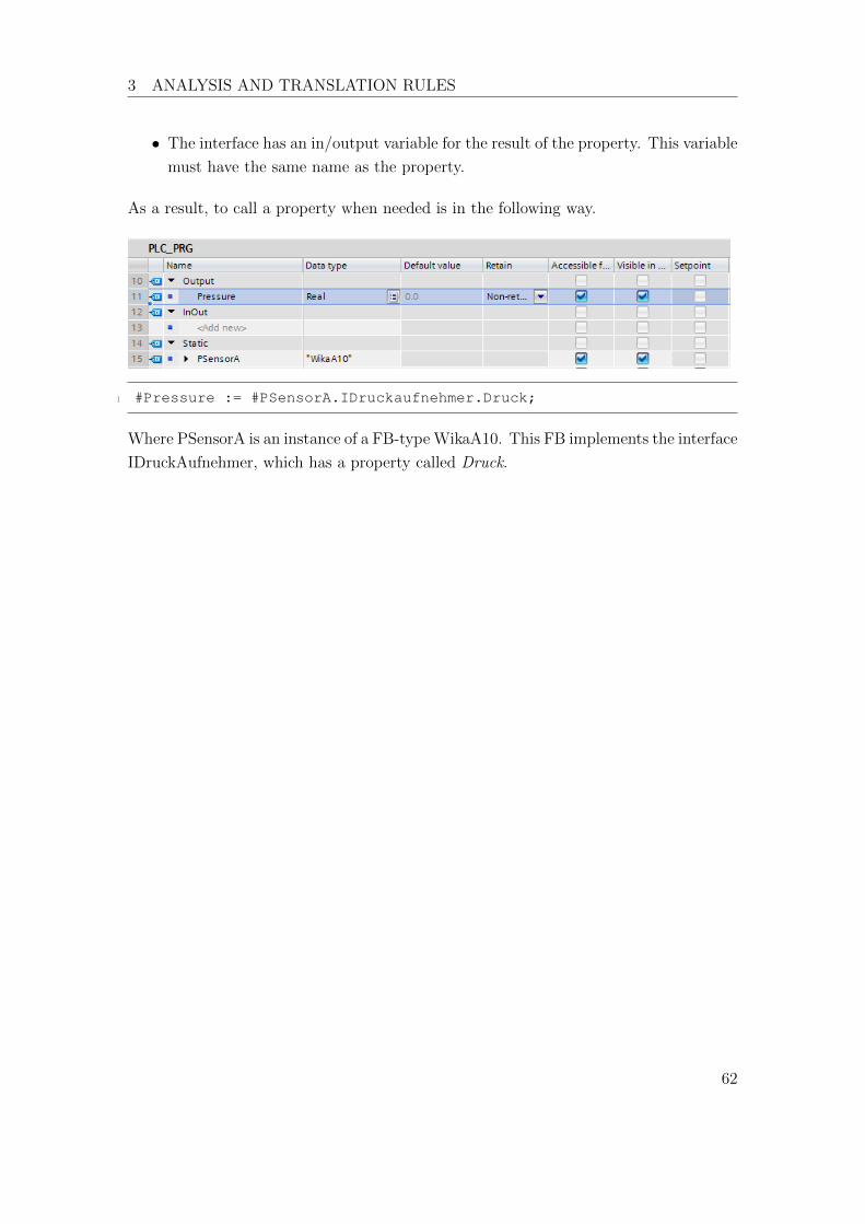
3 ANALYSIS AND TRANSLATION RULES
• The interface has an in/output variable for the result of the property. This variable
must have the same name as the property.
As a result, to call a property when needed is in the following way.
1 #Pressure := #PSensorA.IDruckaufnehmer.Druck;
Where PSensorA is an instance of a FB-typeWikaA10. This FB implements the interface
IDruckAufnehmer, which has a property called Druck.
62
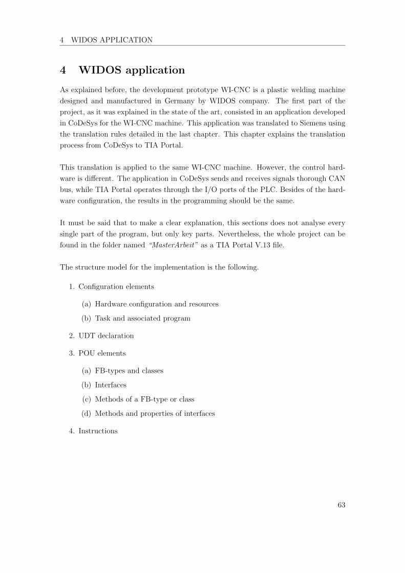
4 WIDOS APPLICATION
4 WIDOS application
As explained before, the development prototype WI-CNC is a plastic welding machine
designed and manufactured in Germany by WIDOS company. The first part of the
project, as it was explained in the state of the art, consisted in an application developed
in CoDeSys for the WI-CNC machine. This application was translated to Siemens using
the translation rules detailed in the last chapter. This chapter explains the translation
process from CoDeSys to TIA Portal.
This translation is applied to the same WI-CNC machine. However, the control hard-
ware is di↵erent. The application in CoDeSys sends and receives signals thorough CAN
bus, while TIA Portal operates through the I/O ports of the PLC. Besides of the hard-
ware configuration, the results in the programming should be the same.
It must be said that to make a clear explanation, this sections does not analyse every
single part of the program, but only key parts. Nevertheless, the whole project can be
found in the folder named “MasterArbeit” as a TIA Portal V.13 file.
The structure model for the implementation is the following.
1. Configuration elements
(a) Hardware configuration and resources
(b) Task and associated program
2. UDT declaration
3. POU elements
(a) FB-types and classes
(b) Interfaces
(c) Methods of a FB-type or class
(d) Methods and properties of interfaces
4. Instructions
63

4 WIDOS APPLICATION
4.1 Configuration elements
4.1.1 Configuration is CoDeSys
A configuration is composed by resources and tasks. The resources of the project are
one PLC and one HMI. The PLC has a cyclic task, this cyclic task instantiate the main
program PLC PRG. This configuration is shown in the Figure 4-1.
Figure 4-1: CoDeSys configuration
4.1.2 Siemens configuration
The hardware configuration is made in TIA Portal adding devices (resources) to the
project. The hardware configuration is shown in the Figure 4-2.
Figure 4-2: Siemens hardware configuration
64
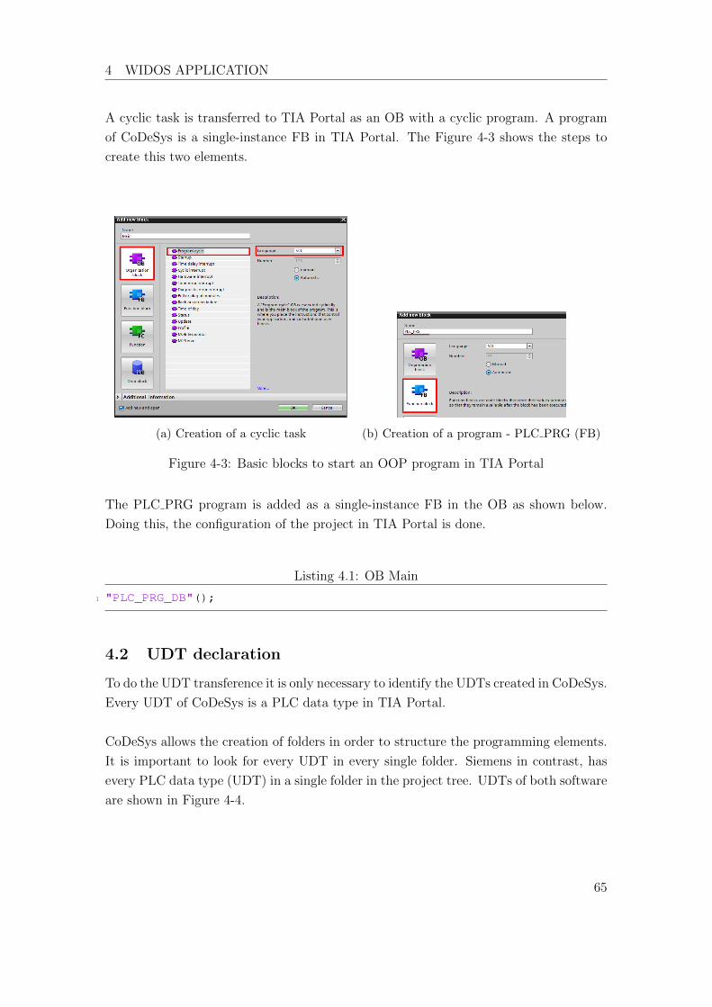
4 WIDOS APPLICATION
A cyclic task is transferred to TIA Portal as an OB with a cyclic program. A program
of CoDeSys is a single-instance FB in TIA Portal. The Figure 4-3 shows the steps to
create this two elements.
(a) Creation of a cyclic task (b) Creation of a program - PLC PRG (FB)
Figure 4-3: Basic blocks to start an OOP program in TIA Portal
The PLC PRG program is added as a single-instance FB in the OB as shown below.
Doing this, the configuration of the project in TIA Portal is done.
Listing 4.1: OB Main
1 "PLC_PRG_DB"();
4.2 UDT declaration
To do the UDT transference it is only necessary to identify the UDTs created in CoDeSys.
Every UDT of CoDeSys is a PLC data type in TIA Portal.
CoDeSys allows the creation of folders in order to structure the programming elements.
It is important to look for every UDT in every single folder. Siemens in contrast, has
every PLC data type (UDT) in a single folder in the project tree. UDTs of both software
are shown in Figure 4-4.
65
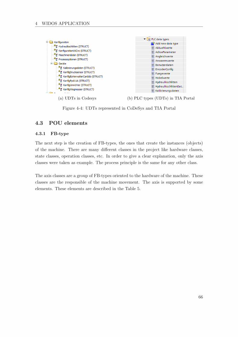
4 WIDOS APPLICATION
(a) UDTs in Codesys (b) PLC types (UDTs) in TIA Portal
Figure 4-4: UDTs represented in CoDeSys and TIA Portal
4.3 POU elements
4.3.1 FB-type
The next step is the creation of FB-types, the ones that create the instances (objects)
of the machine. There are many di↵erent classes in the project like hardware classes,
state classes, operation classes, etc. In order to give a clear explanation, only the axis
classes were taken as example. The process principle is the same for any other class.
The axis classes are a group of FB-types oriented to the hardware of the machine. These
classes are the responsible of the machine movement. The axis is supported by some
elements. These elements are described in the Table 5.
66

4 WIDOS APPLICATION
Name Class name Description
Machine Axis AchseWicnc It is the main controller of the machine.
This class e↵ectuate every machine move-
ment.
Valves VentilblockWICnc These valves are the ones that make pos-
sible the movement of the hydraulic actu-
ators in the base machine.
Frequency con-
verter
UmrichterWicnc This converter controls the hydraulic
pump that generates the oil pressure for
the movement of the machine.
Linear Encoder WegmesserWicnc It measures the movement of the base ma-
chine.
Pressure Sensor WikaA10Can This is a pressure sensor. The sensor mea-
sures the pressure in the base machine.
Proportional
Valve
Ppd11ACan This valve is used to control the oil pres-
sure in the machine.
Table 5: Axis classes and descriptions
4.3.1.1 FB-types in CoDeSys
The project is made of FB-types, there are no declared classes. In the Figure 4-5 is
shown the folder axis classes3.
Figure 4-5: Axis classes in CoDeSys
3In German Achsklassen
67

4 WIDOS APPLICATION
4.3.1.2 FB-types in TIA Portal
Now that the FB-types are recognised, the next step is the translation to TIA Portal.
As the rule says, a FB-type is in TIA Portal a multi-instance FB.
A new FB is created for very FB in CoDeSys and then they are turned into multi-
instance FB. The result is shown in Figure 4-6. After this step, the FB-type declaration
is finished.
Figure 4-6: POUs declared after the classes declaration
4.3.2 Interfaces
This step a↵ronts the problem that interfaces are in CoDeSys only prototypes without
code, but in TIA Portal this concept does not exist. Due to that fact, this step is not
as easy as go to the interface section in CoDeSys and transfer them to TIA Portal.
This section includes an explanation about how to go directly to the FB and see which
interfaces are there implemented. Eventually, the interfaces are to TIA Portal trans-
ferred.
4.3.2.1 Interfaces in CoDeSys
For this topic explanation, the interfaces implemented in the FB Ppd11A are taken as
example. The Figure 4-7 shows the elements of FB Ppd11ACan.
68

4 WIDOS APPLICATION
Figure 4-7: Elements of the FB Ppd11ACan
Those are all the methods and properties that the FB has. It is necessary to di↵erentiate
the methods of the FB from the methods of the interface. To do this, it is important
to identify the interfaces implemented in the FB. The next code shows the declaration
part of the FB Ppd11ACan.
1 FUNCTION_BLOCK Ppd11ACan IMPLEMENTS IFehlerAuslesbar, IDruckregler
The FB implements two interfaces: IFehlerAuslesbar and IDruckregler4. The next step
is to look for the interfaces in the project and see which methods belong to which
interfaces. The Figure 4-8 shows these two interfaces.
Figure 4-8: Elements of the interfaces IFehlerAuslesbar and IDruckregler
With this analysis, it could be figured out that only init method belongs to the FB and
the transference can now be done.
4German words for Error readable and Pressure regulator, respectively
69

4 WIDOS APPLICATION
4.3.2.2 Interfaces in TIA Portal
The interfaces found after the previous analysis are: IFehlerAuslesbar and IDruckregler.
Each interface is transferred to TIA Portal as a multi-instance FB. The result is shown
in Figure 4-9.
Figure 4-9: Interfaces IFehlerAuslesbar and IDruckregler
4.3.3 Methods of a FB-types
In this section, the init method of the FB Ppd11A is explained. The process is the same
for any other FB-type method. Nevertheless, this method is present in many FB-types.
The Init method is a function called just after the start of the PLC. This method set
the initial values and configuration of the objects.
4.3.3.1 Methods of FB-types in CoDeSys
The init method is declared in CoDeSys as following.
1 METHOD Init
2 VAR_INPUT3 pEaAnbindung : POINTER TO EaVerwalterCanSdo;
4 pKonfiguration : POINTER TO KonfigPpd11A;
5 END_VAR
1 IF NOT InitFertig THEN2 pEaVerwalter := pEaAnbindung;
3 pKonfig := pKonfiguration;
4
5 pEaVerwalterˆ.InitialisiereSdo(ADR(Propventil),
Knotenadressen.Kleinspannung, SdoAdrN400.Proportionalventil,
CanDatentyp.Us16, CanSdoPrioritaet.Hoch, FALSE);
6
7 InitFertig := TRUE;
8 END_IF
70
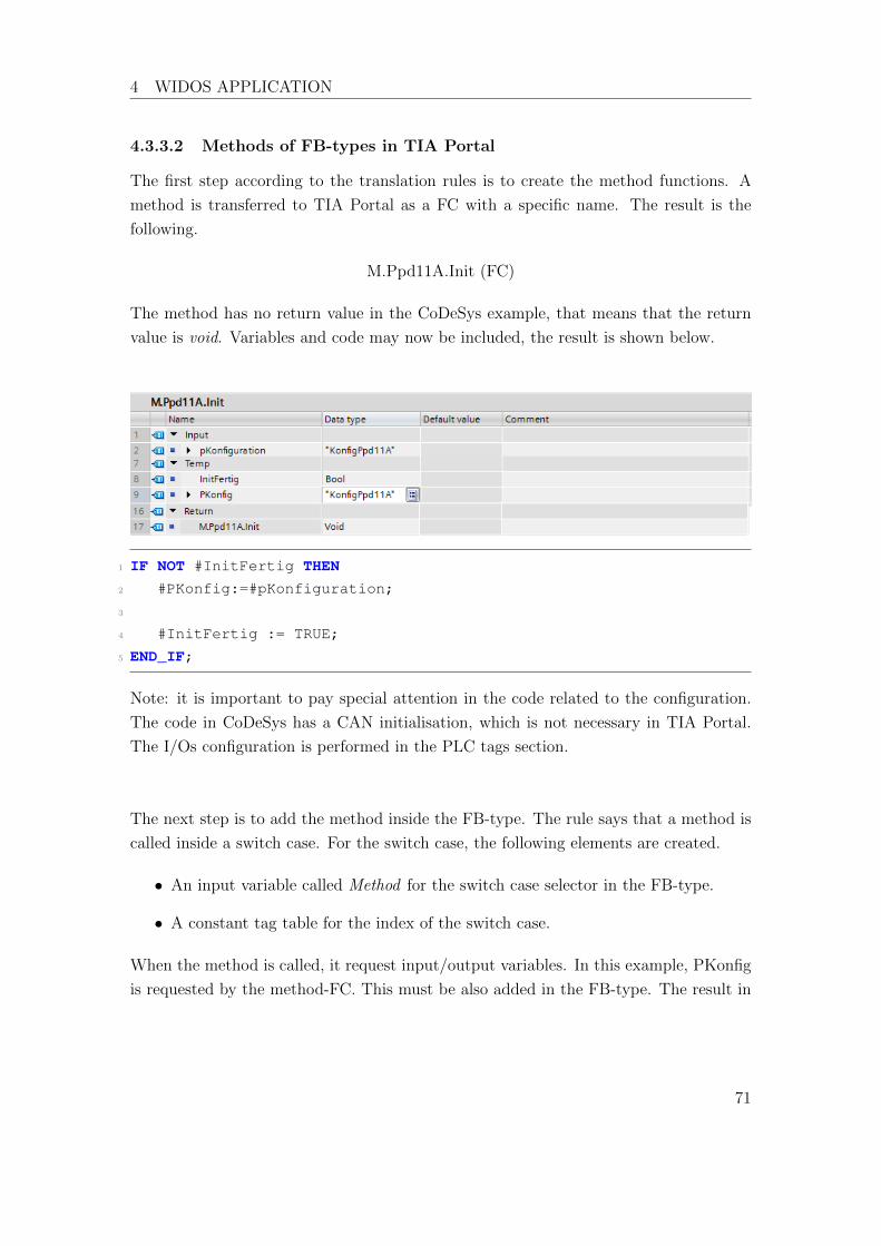
4 WIDOS APPLICATION
4.3.3.2 Methods of FB-types in TIA Portal
The first step according to the translation rules is to create the method functions. A
method is transferred to TIA Portal as a FC with a specific name. The result is the
following.
M.Ppd11A.Init (FC)
The method has no return value in the CoDeSys example, that means that the return
value is void. Variables and code may now be included, the result is shown below.
1 IF NOT #InitFertig THEN2 #PKonfig:=#pKonfiguration;
3
4 #InitFertig := TRUE;
5 END_IF;
Note: it is important to pay special attention in the code related to the configuration.
The code in CoDeSys has a CAN initialisation, which is not necessary in TIA Portal.
The I/Os configuration is performed in the PLC tags section.
The next step is to add the method inside the FB-type. The rule says that a method is
called inside a switch case. For the switch case, the following elements are created.
• An input variable called Method for the switch case selector in the FB-type.
• A constant tag table for the index of the switch case.
When the method is called, it request input/output variables. In this example, PKonfig
is requested by the method-FC. This must be also added in the FB-type. The result in
71
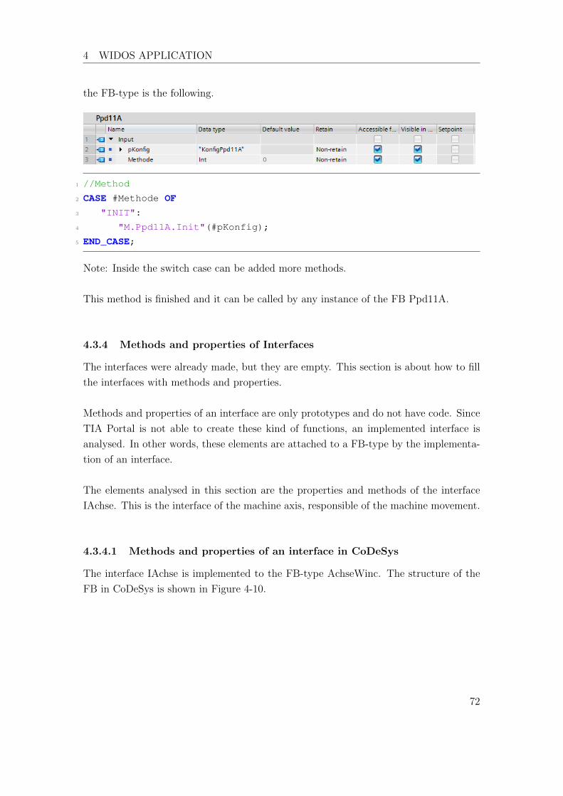
4 WIDOS APPLICATION
the FB-type is the following.
1 //Method
2 CASE #Methode OF3 "INIT":
4 "M.Ppd11A.Init"(#pKonfig);
5 END_CASE;
Note: Inside the switch case can be added more methods.
This method is finished and it can be called by any instance of the FB Ppd11A.
4.3.4 Methods and properties of Interfaces
The interfaces were already made, but they are empty. This section is about how to fill
the interfaces with methods and properties.
Methods and properties of an interface are only prototypes and do not have code. Since
TIA Portal is not able to create these kind of functions, an implemented interface is
analysed. In other words, these elements are attached to a FB-type by the implementa-
tion of an interface.
The elements analysed in this section are the properties and methods of the interface
IAchse. This is the interface of the machine axis, responsible of the machine movement.
4.3.4.1 Methods and properties of an interface in CoDeSys
The interface IAchse is implemented to the FB-type AchseWinc. The structure of the
FB in CoDeSys is shown in Figure 4-10.
72

4 WIDOS APPLICATION
Figure 4-10: Structure of FB WiCnc
4.3.4.2 Methods and properties of an interface in TIA Portal
The process to make a method or property of an interface is similar to the process to
make methods for a FB-type, but the implementation is di↵erent. For this reason, the
creation of the methods is not again explained, but the implementation in the interface.
After the creation of all methods-FC and properties-FC, they must be added inside the
body of the interface. Applying the translation rules, the result of the interface-FB is
the following below.
73
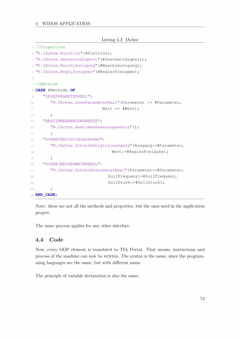
4 WIDOS APPLICATION
Listing 4.2: IAchse
1 //Properties
2 "P.IAchse.Position"(#Position);
3 "P.IAchse.Geschwindigkeit"(#Geschwindigkeit);
4 "P.IAchse.Beschleunigung"(#Beschleunigung);
5 "P.IAchse.Regelfreigebe"(#ReglerFreigabe);
6
7 //Methods
8 CASE #Methode OF9 "LESEPARAMETERREAL":
10 "M.IAchse.LeseParameterReal"(Parameter := #Parameter,
11 Wert => #Wert);
12 ;
13 "BESTIMMEBEWEGUNSWERTE":
14 "M.IAchse.BestimmeBewegungswerte"();
15 ;
16 "SCHREIBEDIGITALAUSGANG":
17 "M.IAchse.SchreibeDigitalausgang"(Ausgang:=#Parameter,
18 Wert:=#ReglerFreigabe);
19 ;
20 "SCHREIBEPARAMETERREAL":
21 "M.IAchse.SchreibParameterReal"(Parameter:=#Parameter,
22 SollFrequenz:=#SollFrequenz,
23 SollDruck:=#SollDruck);
24 ;
25 END_CASE;
Note: these are not all the methods and properties, but the ones used in the application
project.
The same process applies for any other interface.
4.4 Code
Now, every OOP element is translated to TIA Portal. That means, instructions and
process of the machine can now be written. The syntax is the same, since the program-
ming languages are the same, but with di↵erent name.
The principle of variable declaration is also the same.
74
5 EVALUATION OF THE PROJECT
5 Evaluation of the project
5.1 Results and observations
The main purpose about finding out transfer rules to convert code from CoDeSys V3.5 to
TIA Portal V13 was successfully. It was hardly at the begging to find the exact behaviour
and definition of every CoDeSys element. However, the norm was very helpful with this
problem. The norm IEC 61131-3 explains in detail every element of a PLC programming
language including OOP elements. Based in the IEC norm and comparing results with
CoDeSys, the translation rules were successfully written.
5.1.1 Result of configuration translation
This topic was a little challenging, the configuration is in both systems pretty di↵er-
ent; although, a translation way was found. The norm declares that a configuration is
composed by resources and tasks, which means, a configuration is the hardware con-
figuration composed by devices. A hardware configuration can be made in TIA Portal
adding devices, like HMI or decentralised modules.
Another challenge was faced in the application, the hardware configuration in the WI-
CNC machines is composed by a panel PC communicated through CAN interface with
the machine. This configuration was completely changed due to the I/O ports of the
PLC. This change in the configuration also modifies the code instructions related with
the hardware communication. Nevertheless, a transfer rule could be found in every case .
Therefore, a translation of configuration is successfully achieved only after a hardware
analysis.
5.1.2 Result of Program translation
A ‘program’ was a programming element not available in TIA Portal. However, a success-
fully translation could be found. After reading the concept and specifications detailed
in the norm, it was found out that the realisation of programs in TIA Portal is possible.
Rules about the translation of programs could be found, but not only that, also about
the association of programs in tasks. With these achievements, the properly translation
of programs and its association were finished.
75

5 EVALUATION OF THE PROJECT
5.1.3 Result of FB translation
The FB translation was one of the most accurate and perfect translation. Both FB-types
and FB-instance were already in TIA Portal, but named after another name. After read-
ing the concept in the IEC norm, it was found out that FB-types are multi-instances
FBs and FB-instances are variables of type multi-instance FBs.
This element is also one of the most important ones in the project. The programming
structure of CoDeSys uses only FB and does not make class declarations. Therefore, the
successfully translation of this element was an important achievement for the project.
5.1.4 Result of functions
By functions’ are involved methods of a class, methods of an interface and properties.
This translation was achieved though lot of conditions in the implementation. In spite
that all methods are as simply FC to TIA Portal translated, the association of these to
classes or interfaces was complicated.
These functions needed of extra elements in order to find a proper translation. For
example, extra declaration of variables, constants and switch cases. However, after all
those extra elements and conditions a successfully approach for a proper translation was
achieved. Notwithstanding, it could be worthy to invest more time in the improvement
of this translation.
76

5 EVALUATION OF THE PROJECT
5.2 Results and evaluation of the WI-CNC application
The result of the application is the translation of the application framework of the WI-
CNC made in CoDeSys by Tilmann Glucks. The translation in TIA Portal was able to
reproduce all OOP elements of the CoDeSys programming structure. The PLC was also
programmed in order to e↵ectuate common tasks like the movement of the base machine
and the correctly lecture of pressure sensors and encoder.
This e↵ectiveness of the translation rules makes programming modules and structure
reusable. With this, the programming timing is reduced, which means that the develop-
ment timing of a machine is also reduced. This helps WIDOS to deliver their products
quicker.
The translation rules make possible the representation of OOP elements in Siemens.
This is an advantage, because OOD and modern system models like MBSE can be ap-
plied also in Siemens, not only that, but also OOP makes complex programming easier
to develop and comprehend.
The application of the translation rules in WIDOS saves much money due to the following
advantages:
• Avoiding the needing to hire external Siemens programmers.
• Avoiding the needing to write a whole new program only for Siemens.
• Avoiding to make a new programming design.
• Saving programming timing.
• It can deliver their products faster, no mater the PLC required by the client.
77
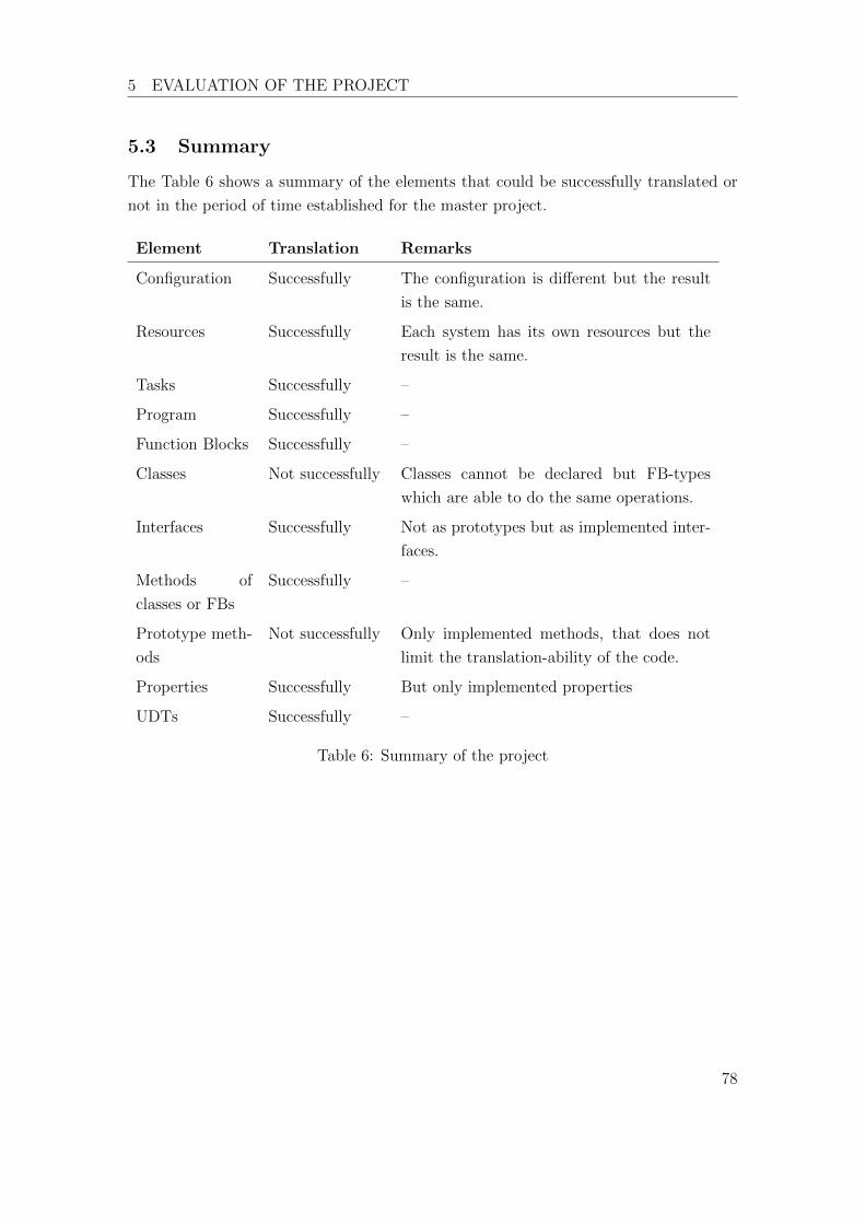
5 EVALUATION OF THE PROJECT
5.3 Summary
The Table 6 shows a summary of the elements that could be successfully translated or
not in the period of time established for the master project.
Element Translation Remarks
Configuration Successfully The configuration is di↵erent but the result
is the same.
Resources Successfully Each system has its own resources but the
result is the same.
Tasks Successfully –
Program Successfully –
Function Blocks Successfully –
Classes Not successfully Classes cannot be declared but FB-types
which are able to do the same operations.
Interfaces Successfully Not as prototypes but as implemented inter-
faces.
Methods of
classes or FBs
Successfully –
Prototype meth-
ods
Not successfully Only implemented methods, that does not
limit the translation-ability of the code.
Properties Successfully But only implemented properties
UDTs Successfully –
Table 6: Summary of the project
78
6 FUTURE PROSPECTS
6 Future prospects
The norm IEC 61131-3 is large and deals with many other aspects of PLC programming
systems. This master thesis details the most important ones so roughly. Nevertheless,
a whole translation of the norm IEC 61131-3 can be done to be applied in TIA Portal.
Documenting which specifications are able to be translated or not.
Talking about the translation of OOP elements, some of them can be improved and
some others no. For example, FBs are very good translated and have no needing of
improvement. On the other hand, elements like methods and properties of interfaces
can be improved, making cleaner programming structures.
Another future prospect is the creation of a software able to recognise elements of a
CoDeSys framework and make an automatic translation to TIA Portal. It may begin
not by giving an already TIA Portal project file but a help file to make a translation
easier and quicker.
79
REFERENCES
References
[AG17] Siemens AG. Simatic et 200sp - system overview, 2017.
[CEN04] CENELEC. Din en 61131-1, 2004.
[CEN13] CENELEC. Din en 61131-3, 2013.
[Che76] P. Chen. The entity-relationship model: Toward a unified view of data. 1976.
[DM13] Charles E. Dickerson and Dimitri Mavris. A brief history of models and model
based systems engineering and the case for relational orientation. 2013.
[Glu16] Tilmann Gluecks. Entwicklung einer portablen objektorientierten
steuerungssoftware fur kunststo↵schweißmaschinen. Master’s thesis, 2016.
[Hol07] J. Holt. UML for System Engineering. 2007.
[HP13a] Jon Holt and Simon Perry. Introduction to model-based systems engineering,
chapter 5, page 121. The Institution of Engineering and Technology, 2013.
[HP13b] Jon Holt and Simon Perry. The SysML notation, chapter 1, page 7. The
Institution of Engineering and Technology, 2013.
[JT10] Karl-Henz John and Michael Tiegelkamp. IEC 61131-3:Programming Indus-
trial Automation System. Springer-Verlag, 2010.
[Sie13] AG Siemens. Standards compliance according to iec 61131-3, 2013.
[Sie16] AG Siemens. S7-1200 System Manual. Siemens AG, Division Digital Factory
Postfach 48 48 90026 NURNBERG Deutschland, August 2016.
[Sol17] 3S Smart Software Solutions. Codesys in embedded automation, 2017.
[WID12] WIDOS. Betriebsanleitung WIDOS 4600, 2012.
[WID15a] WIDOS. Original Betriebsanleitung, 2015.
[WID15b] WIDOS. Working Instructions WIDOS WI-CNC, 2015.
80
A TRANSLATION RULES
Appendices
A Translation rules
A.1 Data type
A.1.1 UDT
A.1.1.1 Problem
UDTs are not found in Siemens.
A.1.1.2 Translation rule
The UDTs of CoDeSys are the PLC Data types in TIA Portal.
A.1.1.3 Example
(a) UDTs in Codesys (b) PLC types (UDTs) in TIA Portal
A.1.2 VAR section
A.1.2.1 Problem
The variable section VAR is not found in TIA Portal.
A.1.2.2 Translation rule
The VAR section of CoDeSys can be taken as the Static variable section of Siemens.
81
A TRANSLATION RULES
A.1.2.3 Example
1 VAR2 pKonfig : POINTER TO KonfigUmrichter;
3 InitFertig : BOOL;
4 END_VAR
A.1.3 Global variables
A.1.3.1 Problem
Global variables cannot be declared in TIA Portal.
A.1.3.2 Translation rule
The variable declaration VAR GLOBAL can be transferred to Siemens as a Data Base
POU.
A.1.3.3 Example
1 VAR_GLOBAL2 Rezept : RezeptWiCnc;
3 Konfiguration : KonfigurationWiCnc;
4 SchlittenDb : HydraulikschlittenDatenbank;
5 END_VAR
82
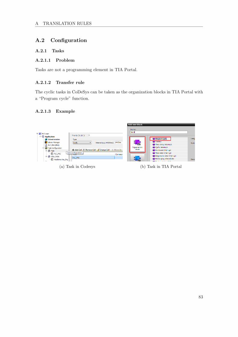
A TRANSLATION RULES
A.2 Configuration
A.2.1 Tasks
A.2.1.1 Problem
Tasks are not a programming element in TIA Portal.
A.2.1.2 Transfer rule
The cyclic tasks in CoDeSys can be taken as the organization blocks in TIA Portal with
a “Program cycle” function.
A.2.1.3 Example
(a) Task in Codesys (b) Task in TIA Portal
83

A TRANSLATION RULES
A.3 POUs
A.3.1 Program
A.3.1.1 Problem
Programs are not program elements available in Siemens.
A.3.1.2 Transfer rule
A program can be represented in TIA Portal as a single-instance FB, which is instanti-
ated inside an OB (task).
A.3.1.3 Example
A.3.2 FB-type
A.3.2.1 Problem
TIA Portal does not name FB-types after that name.
A.3.2.2 Transfer rule
A FB-type of CoDeSys is a multi-instance FB in Siemens.
A.3.2.3 Example
84
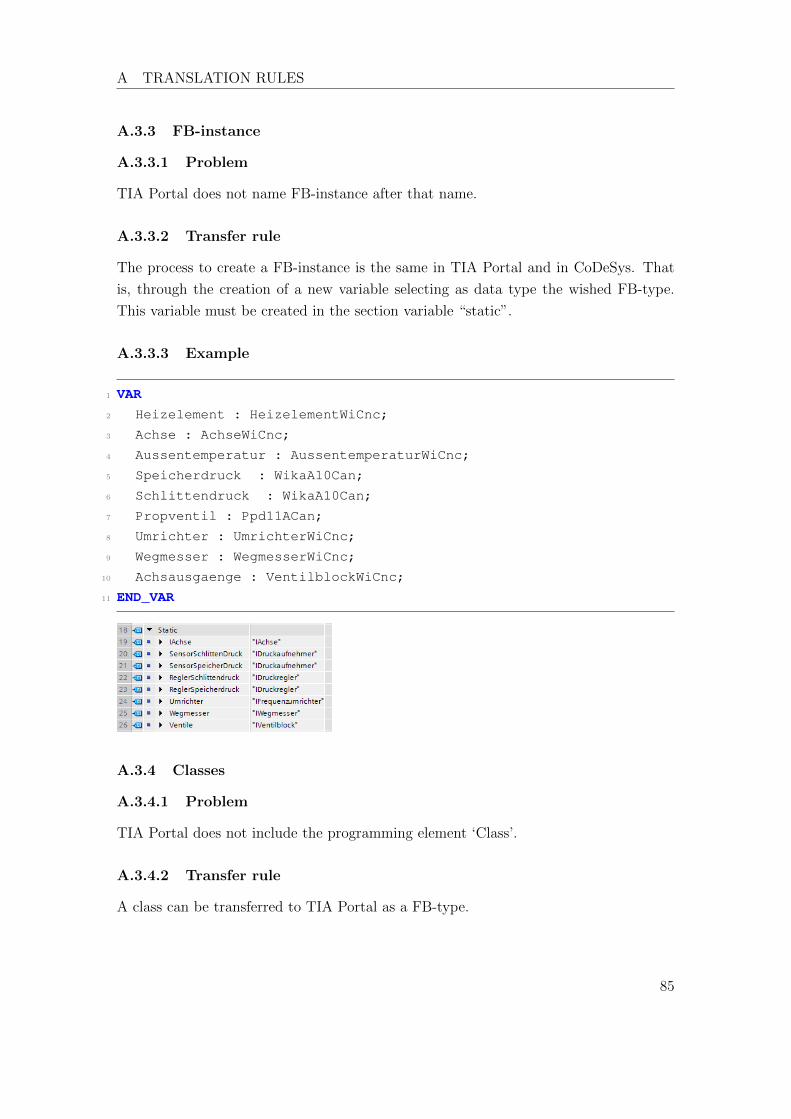
A TRANSLATION RULES
A.3.3 FB-instance
A.3.3.1 Problem
TIA Portal does not name FB-instance after that name.
A.3.3.2 Transfer rule
The process to create a FB-instance is the same in TIA Portal and in CoDeSys. That
is, through the creation of a new variable selecting as data type the wished FB-type.
This variable must be created in the section variable “static”.
A.3.3.3 Example
1 VAR2 Heizelement : HeizelementWiCnc;
3 Achse : AchseWiCnc;
4 Aussentemperatur : AussentemperaturWiCnc;
5 Speicherdruck : WikaA10Can;
6 Schlittendruck : WikaA10Can;
7 Propventil : Ppd11ACan;
8 Umrichter : UmrichterWiCnc;
9 Wegmesser : WegmesserWiCnc;
10 Achsausgaenge : VentilblockWiCnc;
11 END_VAR
A.3.4 Classes
A.3.4.1 Problem
TIA Portal does not include the programming element ‘Class’.
A.3.4.2 Transfer rule
A class can be transferred to TIA Portal as a FB-type.
85
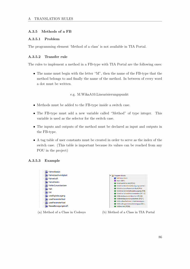
A TRANSLATION RULES
A.3.5 Methods of a FB
A.3.5.1 Problem
The programming element ‘Method of a class’ is not available in TIA Portal.
A.3.5.2 Transfer rule
The rules to implement a method in a FB-type with TIA Portal are the following ones:
• The name must begin with the letter “M”, then the name of the FB-type that the
method belongs to and finally the name of the method. In between of every word
a dot must be written.
e.g. M.WikaA10.Linearisierungspunkt
• Methods must be added to the FB-type inside a switch case.
• The FB-type must add a new variable called “Method” of type integer. This
variable is used as the selector for the switch case.
• The inputs and outputs of the method must be declared as input and outputs in
the FB-type.
• A tag table of user constants must be created in order to serve as the index of the
switch case. (This table is important because its values can be reached from any
POU in the project)
A.3.5.3 Example
(a) Method of a Class in Codesys (b) Method of a Class in TIA Portal
86

A TRANSLATION RULES
A.3.6 Interfaces
A.3.6.1 Problem
An interface is not a programming element available in TIA Portal.
A.3.6.2 Transfer rules
• An interface-FB, starts its name with an “I”.
• An interface is transferred to TIA Portal as a multi-instance FB without instruc-
tions.
A.3.6.3 Example
(a) Interfaces in Codesys (b) Interfaces in TIA Portal
A.3.7 Methods of an interface
A.3.7.1 Problem
Methods of an interface are not a programming element available in TIA Portal. TIA
Portal is not able to do prototype-functions.
A.3.7.2 Transfer rule
The rules to implement a method in an interface with TIA Portal are the following ones:
• The name must begin with the letter “M”, then the name of the interface that the
method belongs to and finally the name of the method. In between of every word
a dot must be written.
87
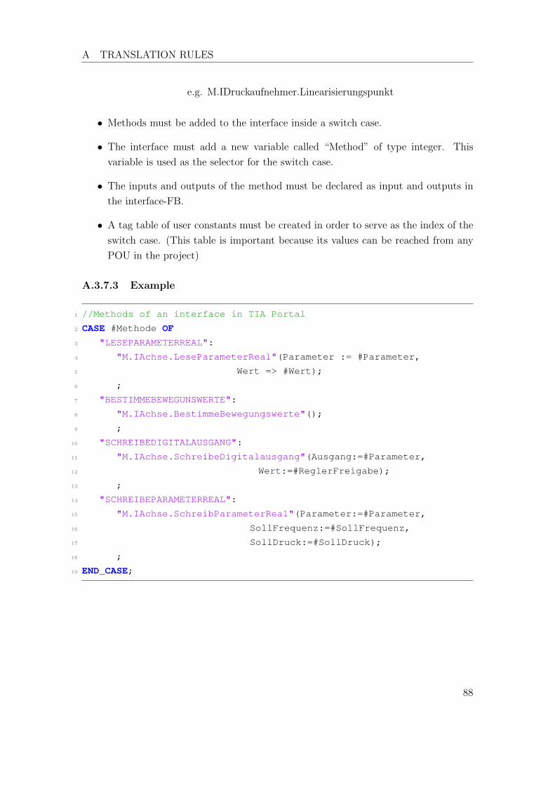
A TRANSLATION RULES
e.g. M.IDruckaufnehmer.Linearisierungspunkt
• Methods must be added to the interface inside a switch case.
• The interface must add a new variable called “Method” of type integer. This
variable is used as the selector for the switch case.
• The inputs and outputs of the method must be declared as input and outputs in
the interface-FB.
• A tag table of user constants must be created in order to serve as the index of the
switch case. (This table is important because its values can be reached from any
POU in the project)
A.3.7.3 Example
1 //Methods of an interface in TIA Portal
2 CASE #Methode OF3 "LESEPARAMETERREAL":
4 "M.IAchse.LeseParameterReal"(Parameter := #Parameter,
5 Wert => #Wert);
6 ;
7 "BESTIMMEBEWEGUNSWERTE":
8 "M.IAchse.BestimmeBewegungswerte"();
9 ;
10 "SCHREIBEDIGITALAUSGANG":
11 "M.IAchse.SchreibeDigitalausgang"(Ausgang:=#Parameter,
12 Wert:=#ReglerFreigabe);
13 ;
14 "SCHREIBEPARAMETERREAL":
15 "M.IAchse.SchreibParameterReal"(Parameter:=#Parameter,
16 SollFrequenz:=#SollFrequenz,
17 SollDruck:=#SollDruck);
18 ;
19 END_CASE;
88
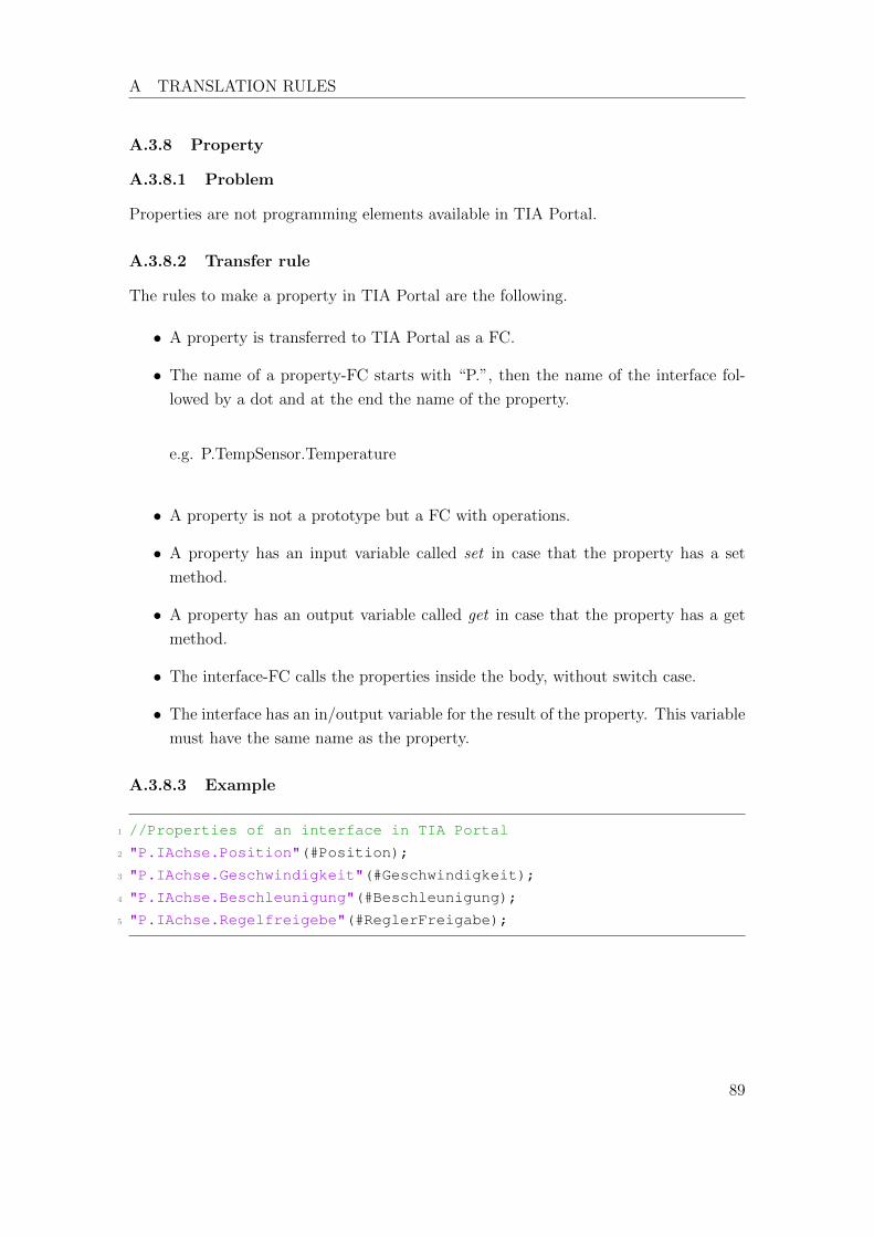
A TRANSLATION RULES
A.3.8 Property
A.3.8.1 Problem
Properties are not programming elements available in TIA Portal.
A.3.8.2 Transfer rule
The rules to make a property in TIA Portal are the following.
• A property is transferred to TIA Portal as a FC.
• The name of a property-FC starts with “P.”, then the name of the interface fol-
lowed by a dot and at the end the name of the property.
e.g. P.TempSensor.Temperature
• A property is not a prototype but a FC with operations.
• A property has an input variable called set in case that the property has a set
method.
• A property has an output variable called get in case that the property has a get
method.
• The interface-FC calls the properties inside the body, without switch case.
• The interface has an in/output variable for the result of the property. This variable
must have the same name as the property.
A.3.8.3 Example
1 //Properties of an interface in TIA Portal
2 "P.IAchse.Position"(#Position);
3 "P.IAchse.Geschwindigkeit"(#Geschwindigkeit);
4 "P.IAchse.Beschleunigung"(#Beschleunigung);
5 "P.IAchse.Regelfreigebe"(#ReglerFreigabe);
89