Embed Size (px)
Citation preview

These slides incorporate figures from Digital DesignPrinciples and Practices, third edition, by John F.Wakerly, Copyright 2000, and are used by permission. NO permission is given to re-use or publish thesefigures, in either original or modified form, in printed,electronic or any other format.

Slide Set 10
Sequential machines

Clocked synchronous state machines:Mealy:
Moore:(next state)
(next state)

Mealy machine with pipelined outputs---resynchronized

Flip-flop characteristic equations:
D Q+ = DD with enable Q+ = DEN + QEN’JK Q+ = J Q’ + K’ QT Q+ = Q’T with enable Q+ = Q’EN + Q EN’

Example: analysis with state machine (D flip-flops)
Goals:• Characterize as Mealy or Moore machine• Determine next-state as function of inputs and current state• Determine output as function of current state (Moore) or
as function of current state and current inputs (Mealy)• Express as machine behavior as state/output table or as state diagram• Formulate English description of machine behavior

Q0+ = D0Q1+ = D1
D0 = F (Q1, Q0, EN)D1 = G (Q1, Q0, EN)
ENQ1 Q0 0 1
00 01 10 11
For Q1+:
0011

Derive truth tables from diagram
ENQ1 Q0 0 1 00 00 01 01 01 10 10 10 11 11 11 00
next state: Q1+ Q0+
EN S 0 1 A A B B B C C C D D D A
next state: S+
Rename states
00 => A01 => B10 => C11 => D
ENQ1 Q0 0 1 00 00,0 01,0 01 01,0 10,0 10 10,0 11,0 11 11,0 00,1
next state: Q1+ Q0+output (MAX)
ENQ1 Q0 0 1 A A,0 B,0 B B,0 C,0 C C,0 D,0 D D,0 A,1
next state: S+output (MAX)

Equivalent state diagram--- Mealy machine has outputs on transition arcs
English description:Machine counts EN pulses mod 4,raises MAX when count will achieve 0 mod 4 on next clock

Remove input connection to output logic => Moore machine
X
Same analysis approach:• Determine next-state and output functions• Express as state/output table and/or as state diagram
Note: MAX = 1 only when Q1=Q0=1

State table:
State diagram:
Moore machine• single output column• outputs in state circles
EN MAX S 0 1 A A B 0 B B C 0 C C D 0 D D A 1
next state: S+ and output (MAX)
English description: Machine counts EN pulses mod 4, raises MAXS whencurrent count is 3 mod 4.

Can use complemented outputs to save inverters:
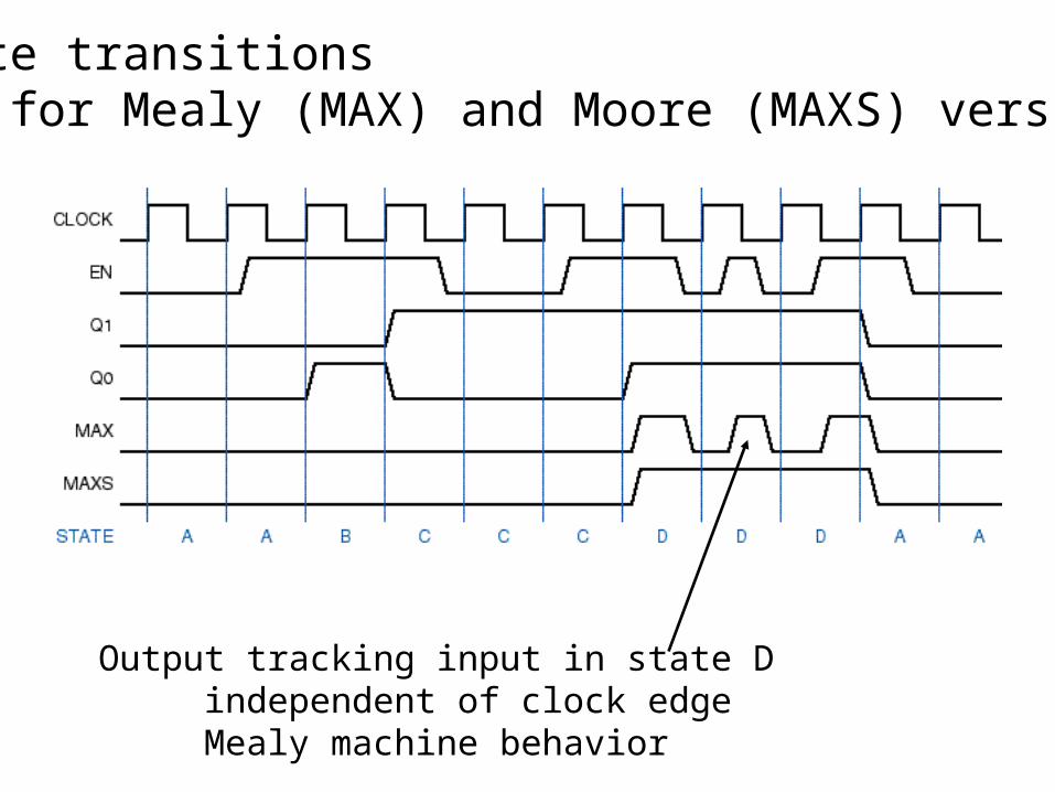
State transitions--- for Mealy (MAX) and Moore (MAXS) version
Output tracking input in state Dindependent of clock edgeMealy machine behavior
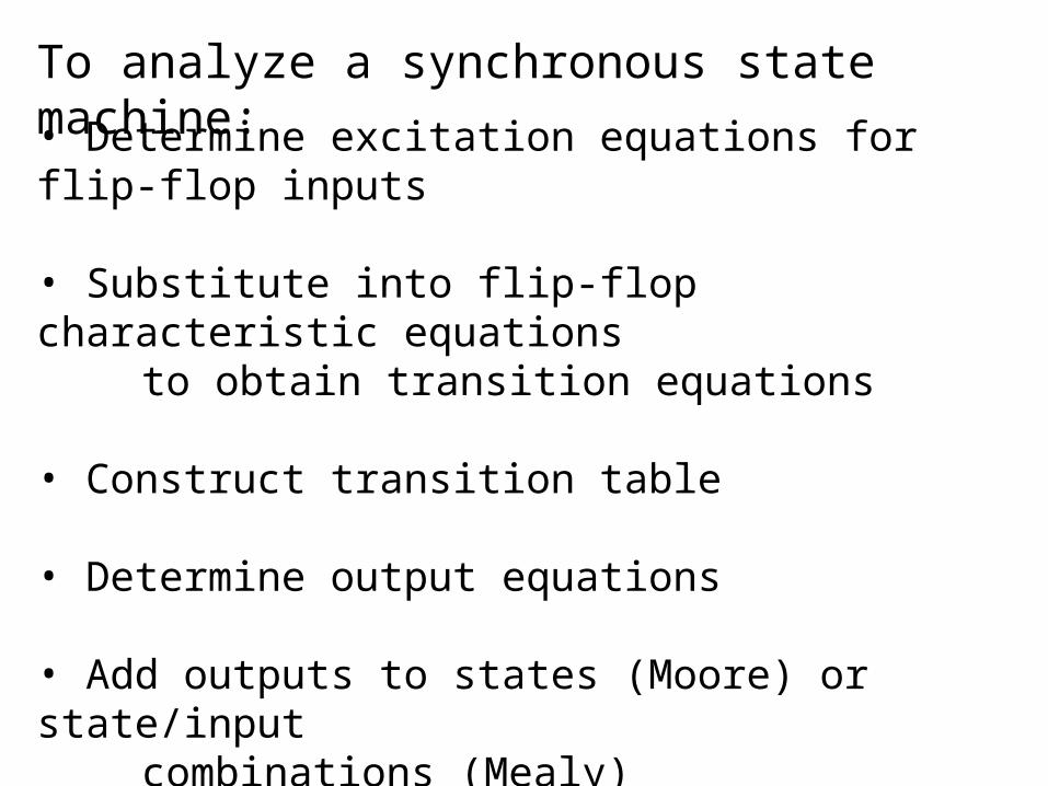
To analyze a synchronous state machine:
• Determine excitation equations for flip-flop inputs
• Substitute into flip-flop characteristic equations to obtain transition equations
• Construct transition table
• Determine output equations
• Add outputs to states (Moore) or state/inputcombinations (Mealy)
• Name states and draw state diagram

Another example: Q0+ = D0 = Q1’X + Q0X’ + Q2Q1+ = D1 = Q2’Q0X + Q1X’ + Q2Q1Q2+ = D2 = Q2Q0’ + Q0’X’Y
Z1 = Q2Q1’ + Q0’Z2 = Q2Q1 + Q2Q0’

State table (Moore machine)

00
(10, 11)
01
State diagram
note alternative conventions for arc labelsX alone means Y can be either 0 or 1same as two arcs with 10 and 11or a single arc with multiple labels

Example: JK flip-flops
J0 = XY’K0 = XY’ + YQ1J1 = XQ0 + YK1 = YQ0’ + XY’Q0
characteristic equation: Q+ = JQ'+K'Q
Q0+ = J0Q0’ + K0’Q0 = XY’Q0’ + X’Y’Q0 +
X’Q1’Q0 + YQ1’Q0Q1+ =
Z = XQ1Q0 + YQ1’Q0’


00/0
10/0
(01,11)/1

Design example:
1, if repeats its previous value0
0, otherwise
1 aborts 1-to-0 transition
AB Z
B Z

ABMeaning S 00 01 11 10 Z
Initial state INIT 0...
ABMeaning S 00 01 11 10 Z
Initial state INIT A0 A0 A1 A1 0Got a 0 on A A0 0Got a 1 on A A1 0
...
Establish tentative state transitions

ABMeaning S 00 01 11 10 Z
Initial state INIT A0 A0 A1 A1 0Got a 0 on A A0 OK OK A1 A1 0Got a 1 on A A1 0Repeat on A OK 1
...

ABMeaning S 00 01 11 10 Z
Initial state INIT A0 A0 A1 A1 0Got a 0 on A A0 OK OK A1 A1 0Got a 1 on A A1 A0 A0 OK OK 0Repeat on A OK 1
...

ABMeaning S 00 01 11 10 Z
Initial state INIT A0 A0 A1 A1 0Got a 0 on A A0 OK OK A1 A1 0Got a 1 on A A1 A0 A0 OK OK 0Repeat on A OK ? OK OK ? 1
...
if two equal inputs are 0, want to stay in OKelse want to return to A0
if two equal inputs are 1, want to stay in OKelse want to return to A1

ABMeaning S 00 01 11 10 Z
Initial state INIT A0 A0 A1 A1 0Got a 0 on A A0 OK0 OK0 A1 A1 0Got a 1 on A A1 A0 A0 OK1 OK1 0Equal, last 0 OK0 OK0 OK0 OK1 A1 1Equal, last 1 OK1 1

ABMeaning S 00 01 11 10 Z
Initial state INIT A0 A0 A1 A1 0Got a 0 on A A0 OK0 OK0 A1 A1 0Got a 1 on A A1 A0 A0 OK1 OK1 0Equal, last 0 OK0 OK0 OK0 OK1 A1 1Equal, last 1 OK1 A0 OK0 OK1 OK1 1

Test design on input scenarios

ABS 00 01 11 10 Z
INIT A0 A0 A1 A1 0A0 OK0 OK0 A1 A1 0A1 A0 A0 OK1 OK1 0OK0 OK0 OK0 OK1 A1 1OK1 A0 OK0 OK1 OK1 1
Assign bit patterns to the five states
State Simple Decomposed One-hot Almost one-hot
INIT 000 000 00001 0000A0 001 100 00010 0001A1 010 101 00100 0010OK0 011 110 01000 0100OK1 100 111 10000 1000
Some alternatives
85! 56(120) 6720 choices
5
first bit: initial or workingsecond bit: pending or pattern recognizedthird bit: pending or recognized pattern with 0 or with 1

Transition/output table (decomposed assignment)
• With D flip-flops, excitation table is identical to transition table• Have three combinational design problems
for Q1+ = D1, Q2+ = D2, Q3+ = D3

Develop excitation equations
• Assume unused states have next-state = 000
=> 9 NAND gates

Assume “don’t care” for transitions from unused states:
D1 = 1D2 = Q3’Q1A’ + Q3A + Q2BD3 = A
=> 4 NANDS


Same example using ABEL
• Note about reset inputs:– You always need a “power-on” reset input for a
sequential circuit.– Previous example did not use synchronous reset
because of manual-synthesis complexity.– Asynchronous reset is sometimes used (PR and
CLR inputs of flip-flops).

• Note definition of “extra” states.
State assignmentuses simple sequential binary patterns

“State Diagram”
This essentially mimics the state table.

Final touches
• Good behavior for extra statesstate XTRA1: GOTO INIT;state XTRA2: GOTO INIT;state XTRA3: GOTO INIT;
• Clock and output equations
equations
QSTATE.CLK = CLOCK; QSTATE.OE = 1;Z = (QSTATE == OK0) # (QSTATE == OK1);
• Alternative state assignments are easy– Modify state definitions and possibly output pins and extra
states.– Unspecified states go to 0,0,…0.

ABEL-derived excitation equations
• Equivalent to what was derived by hand, with the addition of the RESET input.
Q3.FB ??next slide

Qualified signals from flip-flops.CLK or .C clock.AR asynchronous clear.AP asynchronous preset.OE output enable.Q direct output.FB output after programmed inversion.PIN output appearing on pin

ABS 00 01 11 10 Z
INIT A0 A0 A1 A1 0A0 OK0 OK0 A1 A1 0A1 A0 A0 OK1 OK1 0OK0 OK0 OK0 OK1 A1 1OK1 A0 OK0 OK1 OK1 1
Same exampleuse JK flip-flopsdecomposed assignment
ABQ2 Q1 Q0 00 01 11 10 Z
000 100 100 101 101 0100 110 110 101 101 0101 100 100 111 111 0110 110 110 111 101 1111 100 110 111 111 1

Separately for each AB input,add columns for excitations (Ji, Ki) for each flip-flop
ABQ2 Q1 Q0 00 01 11 10 J2 K2 J1 K1 J0 K0 Z
000 100 100 101 101 0100 110 110 101 101 0101 100 100 111 111 0110 110 110 111 101 1111 100 110 111 111 1
Q2+ Q1+ Q0+
Q2 transitions 0 to 1J2 K2 must command set or toggleJ2 K2 = 10 or 11, i.e., 1x
1x
Q1, Q0 hold 0J1 K1, J0 K0 must command reset or holdJ1 K1, J0 K0 = 00 or 01, i.e., 0x
0x 0x

Add columns for excitations (Ji, Ki) for each flip-flop
ABQ2 Q1 Q0 00 01 11 10 J2 K2 J1 K1 J0 K0 Z
000 100 100 101 101 1x 0x 0x 0100 110 110 101 101 x0 1x 0x 0101 100 100 111 111 x0 0x x1 0110 110 110 111 101 x0 x0 0x 1111 100 110 111 111 x0 x1 x1 1
Q2+ Q1+ Q0+
Transition JK command0 => 0 00 or 01 => 0x0 => 1 10 or 11 => 1x1 => 0 01 or 11 => x11 => 1 00 or 10 => x0

Add columns for excitations (Ji, Ki) for each flip-flopAB = 00
Q2 Q1 Q0 Q2+ Q1+ Q0+ J2 K2 J1 K1 J0 K0
000 100 1x 0x 0x100 110 x0 1x 0x101 100 x0 0x x1110 110 x0 x0 0x111 100 x0 x1 x1
AB = 01Q2 Q1 Q0 Q2+ Q1+ Q0+ J2 K2 J1 K1 J0 K0
000 100 1x 0x 0x100 110 x0 1x 0x101 100 x0 0x x1110 110 x0 x0 0x111 110 x0 x0 x1
AB = 11Q2 Q1 Q0 Q2+ Q1+ Q0+ J2 K2 J1 K1 J0 K0
000 101 1x 0x 1x100 101 x0 0x 1x101 111 x0 1x x0110 111 x0 x0 1x111 111 x0 x0 x0
AB = 10Q2 Q1 Q0 Q2+ Q1+ Q0+ J2 K2 J1 K1 J0 K0
000 101 1x 0x 1x100 101 x0 0x 1x101 111 x0 1x x0110 101 x0 x1 1x111 111 x0 x0 x0
Q2 = 0:AB00 01 11 10
00 1 1 1 101 x x x x
Q1 Q0 11 x x x x10 x x x x
Q2 = 1:AB00 01 11 10
00 x x x x01 x x x x
Q1 Q0 11 x x x x10 x x x x
J2 = 1
Q2 = 0:AB00 01 11 10
00 x x x x01 x x x x
Q1 Q0 11 x x x x10 x x x x
Q2 = 1:AB00 01 11 10
00 0 0 0 001 0 0 0 0
Q1 Q0 11 0 0 0 010 0 0 0 0
K2 = 0

Add columns for excitations (Ji, Ki) for each flip-flopAB = 00
Q2 Q1 Q0 Q2+ Q1+ Q0+ J2 K2 J1 K1 J0 K0
000 100 1x 0x 0x100 110 x0 1x 0x101 100 x0 0x x1110 110 x0 x0 0x111 100 x0 x1 x1
AB = 01Q2 Q1 Q0 Q2+ Q1+ Q0+ J2 K2 J1 K1 J0 K0
000 100 1x 0x 0x100 110 x0 1x 0x101 100 x0 0x x1110 110 x0 x0 0x111 110 x0 x0 x1
AB = 11Q2 Q1 Q0 Q2+ Q1+ Q0+ J2 K2 J1 K1 J0 K0
000 101 1x 0x 1x100 101 x0 0x 1x101 111 x0 1x x0110 111 x0 x0 1x111 111 x0 x0 x0
AB = 10Q2 Q1 Q0 Q2+ Q1+ Q0+ J2 K2 J1 K1 J0 K0
000 101 1x 0x 1x100 101 x0 0x 1x101 111 x0 1x x0110 101 x0 x1 1x111 111 x0 x0 x0
Q2 = 0:AB00 01 11 10
00 0 0 0 001 x x x x
Q1 Q0 11 x x x x10 x x x x
Q2 = 1:AB00 01 11 10
00 1 1 0 001 0 0 1 1
Q1 Q0 11 x x x x10 x x x x
J1 = Q0 • A + Q2 • Q0' • A'
Q2 = 0:AB00 01 11 10
00 x x x x01 x x x x
Q1 Q0 11 x x x x10 x x x x
Q2 = 1:AB00 01 11 10
00 x x x x01 x x x x
Q1 Q0 11 0 0 0 110 1 0 0 0
K1 = Q0 • A • B' + Q0' • A' • B'

Add columns for excitations (Ji, Ki) for each flip-flopAB = 00
Q2 Q1 Q0 Q2+ Q1+ Q0+ J2 K2 J1 K1 J0 K0
000 100 1x 0x 0x100 110 x0 1x 0x101 100 x0 0x x1110 110 x0 x0 0x111 100 x0 x1 x1
AB = 01Q2 Q1 Q0 Q2+ Q1+ Q0+ J2 K2 J1 K1 J0 K0
000 100 1x 0x 0x100 110 x0 1x 0x101 100 x0 0x x1110 110 x0 x0 0x111 110 x0 x0 x1
AB = 11Q2 Q1 Q0 Q2+ Q1+ Q0+ J2 K2 J1 K1 J0 K0
000 101 1x 0x 1x100 101 x0 0x 1x101 111 x0 1x x0110 111 x0 x0 1x111 111 x0 x0 x0
AB = 10Q2 Q1 Q0 Q2+ Q1+ Q0+ J2 K2 J1 K1 J0 K0
000 101 1x 0x 1x100 101 x0 0x 1x101 111 x0 1x x0110 101 x0 x1 1x111 111 x0 x0 x0
Q2 = 0:AB00 01 11 10
00 0 0 1 101 x x x x
Q1 Q0 11 x x x x10 x x x x
Q2 = 1:AB00 01 11 10
00 0 0 1 101 x x x x
Q1 Q0 11 0 0 1 110 x x x x
J0 = A
Q2 = 0:AB00 01 11 10
00 x x x x01 x x x x
Q1 Q0 11 x x x x10 x x x x
Q2 = 1:AB00 01 11 10
00 x x x x01 1 1 0 0
Q1 Q0 11 x x x x10 1 1 0 0
K0 = A'

NAND-NAND
J = Q0 • A + Q2 • Q0' • A' JK = Q0 • A • B' + Q0' • A' • B' K
JK flip-flopJ QK Q' CLR
JK flip-flopJ QK Q' CLR
JK flip-flopJ QK Q' CLR
A B
1
0
Z = Q2 • Q1
Q2
Q1
Q0
Z
CLK
initially GNDpull-up to PWRafter small timeinterval


![Advanced Digital Design with the Verilog HDL 1.pdf · Serial Line Codes [Wakerly] are used for serial data transmission or storage. Data recovery](https://img.pdfslide.us/doc/110x75/5ec009c3a5c765543d5ca6d7/advanced-digital-design-with-the-verilog-hdl-1pdf-serial-line-codes-wakerly.jpg)