Embed Size (px)
Citation preview

Th
erm
ow
ells
HA136712 Page 5-1
Thermowells and Assemblies
THERMOWELLS AND THERMOWELL ASSEMBLIES

Th
erm
ow
ells
Thermowells and Assemblies
Page 5-2 HA136712
Introduction
Thermowells provide protection for thermocouples in pressure vessels and pipelines. Athermowell permits checking and replacing the thermocouple without draining the vesselor pipeline.
Material The Longevity Factor. In general, the thermowell material chosen for the installation isgoverned by the corrosion conditions of the well environment. Materials for various servicesare given in the corrosion table. The high mirror polish given to all stainless and monel wellsprovides maximum corrosion resistance.
Occasionally the material consideration is one of strength rather than corrosion. Forexample, a stainless steel well may be required for high pressure water service whereotherwise a brass well would be satisfactory from a corrosion standpoint. Consult thepressure-temperature ratings given for each well type.
The standard materials listed for each well series will cover most requirements. A stockof material is carried at all times to insure fast delivery of wells of standard material.
Connection The Installation Factor. Threaded wells are made in readily welded or brazed materials.This is important for installations requiring seal welding or brazing. The pipe thread providesthe mechanical strength; the weld merely seals.
Insertion Length The Accuracy Factor. The distance from the end of the well to the underside of the thread,or other connection means (designated as “U”), is the insertion length. For best accuracy,this length should be long enough to permit the entire temperature sensitive part of thethermometer bulb to project into the temperature medium being measured. A properlyinstalled thermometer bulb will project into liquid an amount equal to its sensitive length plusat least one inch. In air or gas, the bulb should be immersed its sensitive length plus atleast three inches.
Thermocouples and thermistors have short sensitive lengths and therefore can use thesmallest insertion lengths.
Bi-metal thermometers, resistance temperature detectors, and liquid-in-glass thermometershave bulbs with sensitive portions between one and two inches long. Therefore, the minimumstandard insertion length of 2-1/2” must be entirely immersed in liquid for proper accuracy.
Filled system thermometer bulbs may have sensitive portions from one to several inchesin length. Determine the sensitive length of the bulb before choosing an insertion length.
Above all, be sure the dead length (that required to pass through walls, pipe fittings, etc.)is taken into account when choosing the necessary well insertion length.
Bore Size The Interchangeability Factor. Almost any installation uses several types of temperaturemeasuring instruments. The selection of a standard bore diameter can produce extremeflexibility within the plant. The same well can accommodate a thermocouple, resistancetemperature detector, bi-metal thermometer, or test thermometer. The bore size of wellsshown in this document cover the most commonly used temperature sensing elements asfollows:
Introduction
0.260” Diameter Bore• Bi-metal thermometers (1-1/4” stem)• RTD and MgO thermocouples• Liquid-in-glass test thermometers
(non-armored)• Other elements having 0.252”
maximum diameter
0.385” Diameter Bore• Bi-metal thermometers (3/8” stem)• Thermocouples (14 and 20 gauge)• Liquid-in-glass thermometers
(armored)• Other elements having 0.377”
maximum diameter

Th
erm
ow
ells
HA136712 Page 5-3
Thermowells and Assemblies
Introduction (continued)
Shank – Tapered or Straight The Velocity Rating Factor. Tapered shank wells provide greater stiffness for the samesensitivity. The higher strength to weight ratio gives these wells higher natural frequencythan for equivalent length straight shank wells, thus permitting operation at higher fluidvelocity. See “Velocity Rating of Wells.”
With Lag and No Lag Thermowells are offered either with or without lag. Lag styles permit clearance for insulationor other material surrounding the pipe or process vessel.

Th
erm
ow
ells
Thermowells and Assemblies
Page 5-4 HA136712
Ordering and Pricing Instructions
The following are available:
Thermowell Assemblies (element installed in thermowell)- MgO insulated element- Ceramic insulated element- RTD element
When ordering a complete assembly, you must specify dimensions for the thermowell (Fields5 through 12) and the head to well connector (Field 13) before you can price the element.Therefore, begin the procedure with Field 5 from page 5-10; then complete Fields 13 through15 from page 5-12. Finally, complete Fields 1 through 4 for the required element: MgOinsulated, page 5-6; ceramic insulated, page 5-8; or RTD, page 5-9.
Model No. - - - - Field No. 1 2 3 4 5 6 7 8 9 10 11 12 13 14 15
Replacement Element, with or without Head and Connection
Ordering and Pricing Instructions
.250" "A" (Bore Length)
Connecton Length
1" "T"(Lag)
"U" (Insertion Depth)
(Wrench Flat) 3/4"
Thermowell style, dimensions, material, mounting and options.Fields 5 through 12.
Head to WellConnector.Field 13.
Cold End Termination.Fields 14, 15.
(Internal) Thermocouple type, elements and junction style; or RTD specifications. Fields 1 through 4.
"N"
When ordering a replacement element, you need dimensions from the existing assemblyinto which the element will be placed. The illustration below shows components of a typicalthermowell assembly, and the fields in the model number that specify each of thesecomponents. Note that dimensions “A” and “N” pertain to the sensor element. Various stylesof thermowells (for dimension “A”) are illustrated on pages 5-14, 5-15. Connections (fordimension “N”) are illustrated on page 5-12.
23 1

Th
erm
ow
ells
HA136712 Page 5-5
Thermowells and Assemblies
Ordering and Pricing Instructions (continued)
Thermowell only
If you are ordering a thermowell only, complete the following part number from page 5-10.
Model No. T H 0 0 - - - 0 - 0 0
First, determine the length of the element. If you know the dimensions of the existingthermowell, you can calculate element length by adding A + N. A and N formulas are:
For thermowell styles A, B, E, M, N, P, R (Field 5) A = U + T + 1-1/2”For thermowell styles D, Q, F, S, T, U (Field 5) A = U + T + 2”
For connector codes A, C, E, J (Field 13) N = 3”For connector codes B, D (Field 13) N = nipple length less 1”For connector codes F, K (Field 13) N = combined length of nipples 1 and 2For connector codes 0 and L (Field 13) N is not applicableFor connector codes G and H (Field 13) N is not applicable
After determining the required length of the element, complete Fields 1 through 4: MgOinsulated element, page 5-6; ceramic insulated element, page 5-8; or RTD element, page5-9. Enter zeros in Fields 5 through 12; then complete Fields 13 through 15 from page5-12. If you are not ordering a connection and head, enter zeros in these fields.
NOTE: Even if you are not ordering a connection and head with your element, youmust identify (on your order, by codes from Fields 13 through 15) the connection and headon your present assembly. This information is required by the factory in order to providethe proper lead length.
Model No. - 0 0 0 0 0 - 0 0 0 - - Field No. 1 2 3 4 5 6 7 8 9 10 11 12 13 14 15
1 2
Nipple LengthN
Nipple 1 Nipple 21" Ref.
N 1/2"
1/2"
Field 13, Code "N" =0 0"A, C, E, J 3"B, D Nipple length -1"F, K Combined length of
Nipple 1 and Nipple 2L Not applicableG, H Not applicable
1-1/2"
Th
erm
ow
ells
Thermowells and Assemblies
Page 5-6 HA136712
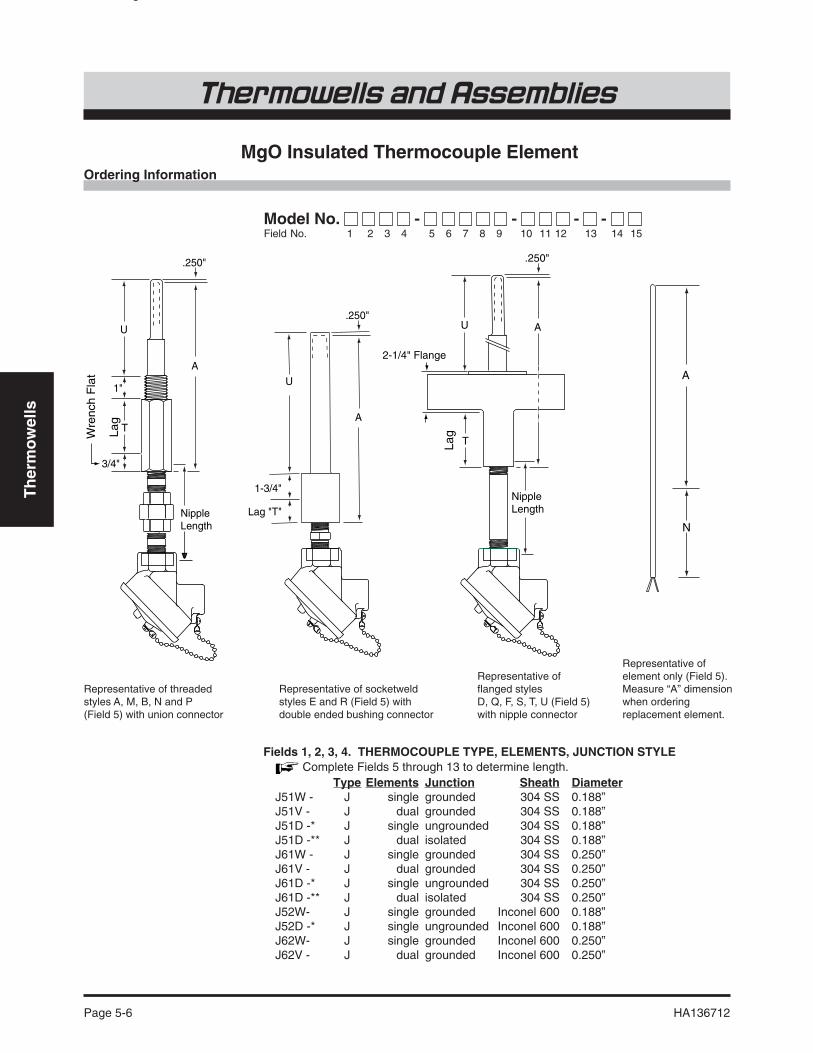
MgO Insulated Thermocouple Element
Model No. - - - - Field No. 1 2 3 4 5 6 7 8 9 10 11 12 13 14 15
MgO T/C Thermowell Elements and Assemblies
Ordering Information
Type Elements Junction Sheath DiameterJ51W - J single grounded 304 SS 0.188”J51V - J dual grounded 304 SS 0.188”J51D -* J single ungrounded 304 SS 0.188”J51D -** J dual isolated 304 SS 0.188”J61W - J single grounded 304 SS 0.250”J61V - J dual grounded 304 SS 0.250”J61D -* J single ungrounded 304 SS 0.250”J61D -** J dual isolated 304 SS 0.250”J52W- J single grounded Inconel 600 0.188”J52D -* J single ungrounded Inconel 600 0.188”J62W- J single grounded Inconel 600 0.250”J62V - J dual grounded Inconel 600 0.250”
Fields 1, 2, 3, 4. THERMOCOUPLE TYPE, ELEMENTS, JUNCTION STYLE Complete Fields 5 through 13 to determine length.
Representative offlanged stylesD, Q, F, S, T, U (Field 5)with nipple connector
.250"
A
Nipple Length
T
U
Lag
2-1/4" Flange
.250"
A
Nipple Length
1"
3/4"
U
TLag
Wre
nch
Fla
t
.250"
A
1-3/4"
U
Lag "T"
Representative of socketweldstyles E and R (Field 5) withdouble ended bushing connector
Representative of threadedstyles A, M, B, N and P(Field 5) with union connector
Representative ofelement only (Field 5).Measure “A” dimensionwhen orderingreplacement element.
A
N

Th
erm
ow
ells
HA136712 Page 5-7
Thermowells and Assemblies
Ordering Information (continued)
J62D -* J single ungrounded Inconel 600 0.250”J62D -** J dual isolated Inconel 600 0.250”J53W- J single grounded 316 SS 0.188”J53D -* J single ungrounded 316 SS 0.188”J63W- J single grounded 316 SS 0.250”J63V - J dual grounded 316 SS 0.250”J63D -* J single ungrounded 316 SS 0.250”J63D -** J dual isolated 316 SS 0.250”K51W- K single grounded 304 SS 0.188”K51D -* K single ungrounded 304 SS 0.188”K61W- K single grounded 304 SS 0.250”K61D -* K single ungrounded 304 SS 0.250”K52W- K single grounded Inconel 600 0.188”K52V - K dual grounded Inconel 600 0.188”K52D -* K single ungrounded Inconel 600 0.188”K52D -** K dual isolated Inconel 600 0.188”K62W- K single grounded Inconel 600 0.250”K62V- K dual grounded Inconel 600 0.250”K62D -* K single ungrounded Inconel 600 0.250”K62D -** K dual isolated Inconel 600 0.250”K53W- K single grounded 316 SS 0.188”K53D - K single ungrounded 316 SS 0.188”K63W- K single grounded 316 SS 0.250”K63V - K dual grounded 316 SS 0.250”K63D -* K single ungrounded 316 SS 0.250”K63D -** K dual isolated 316 SS 0.250”E51W- E single grounded 304 SS 0.188”E51D -* E single ungrounded 304 SS 0.188”E61W- E single grounded 304 SS 0.250”E61D -* E single ungrounded 304 SS 0.250”E63W- E single grounded 316 SS 0.250”E63D -* E single ungrounded 316 SS 0.250”T51W- T single grounded 304 SS 0.188”T51D - T single ungrounded 304 SS 0.188”T61W- T single grounded 304 SS 0.250”T61D - T single ungrounded 304 SS 0.250”T63W- T single grounded 316 SS 0.250”T63V- T dual grounded 316 SS 0.250”T63D - T single ungrounded 316 SS 0.250”
Note: Code “D” in Field 4 represents either of two different junction styles.Therefore you must specify the desired style:*Specify code “W-2” on order. (W-2 = single element, ungrounded junction)**Specify code “V-3” on order. (V-3 = dual element, isolated junction)
Fields 5 through 12. THERMOWELL AND OPTIONS00000-0-00 None. Element, or element with head and connection only.XXXXX-X-XX Complete Thermowell Assembly. See page 5-10
Fields 13 through 15. CONNECTION, COLD END TERMINATION0-00 None. Element onlyX-XX Element with head and connection, or
complete thermowell assembly, see page 5-12
Type Elements Junction Sheath Diameter

Th
erm
ow
ells
Thermowells and Assemblies
Page 5-8 HA136712
Ceramic Insulated Thermocouple Element(for wells with 0.385” bore only)
Model No. - - - - Field No. 1 2 3 4 5 6 7 8 9 10 11 12 13 14 15
Fields 1, 2, 3. THERMOCOUPLE TYPE; WIRE GAUGE Complete Fields 5 through 13 to determine length.
Type Wire Gauge LimitsJ14 - J Iron-Constantan 14 standardJ15 - J Iron-Constantan 14 specialJ20 - J Iron-Constantan 20 standardJ21 - J Iron-Constantan 20 specialK14 - K Chromel-Alumel 14 standardK15 - K Chromel-Alumel 14 specialK20 - K Chromel-Alumel 20 standardK21 - K Chromel-Alumel 20 specialE14 - E Chromel-Constantan 14 standardE15 - E Chromel-Constantan 14 specialE20 - E Chromel-Constantan 20 standardE21 - E Chromel-Constantan 20 specialT14 - T Copper-Constantan 14 standardT15 - T Copper-Constantan 14 specialT20 - T Copper-Constantan 20 standardT21 - T Copper-Constantan 20 special
Field 4. NUMBER OF ELEMENTS AND JUNCTION STYLEW - Single, twisted, groundedV - Dual, twisted, grounded2 - Single, twisted, ungrounded3 - Single, butt welded, grounded4 - Single, butt welded, ungrounded5 - Dual common, butt welded, ungrounded6 - Dual isolated, butt welded, ungrounded
Fields 5 through 12. THERMOWELL AND OPTIONS00000-0-00 None. Element, or element with head and connection only.XXXXX-X-XX Complete thermowell assembly. See page 5-10
Fields 13 through 15. CONNECTION, COLD END TERMINATION0-00 None. Element only.X-XX Element with head and connection, or
complete thermowell assembly, see page 5-12
Ordering Information
Ceramic Insulated Thermowell Elements and Assemblies
J14WJ15WJ20WJ21WK14WK15WK20WK21WE14WE15WE20WE21WT14WT15WT20WT21W
J14VJ15VJ20VJ21VK14VK15VK20VK21VE14VE15VE20VE21VT14VT15VT20V
J144J154J204J214K144K154K204K214E144E154E204E214T144T154T204T214
J145J155J205J215K145K155K205K215E145E155E205E215T145T155T205T215
J146J156J206J216K146K156K206K216E146E156E206E216T146T156T206T216
T21V
J142J152J202J212K142K152K202K212E142E152E202E212T142T152T202T212
J143J153J203J213K143K153K203K213E143E153E203E213T143T153T203T213

Th
erm
ow
ells
HA136712 Page 5-9
Thermowells and Assemblies
Model No. - - - - Field No. 1 2 3 4 5 6 7 8 9 10 11 12 13 14 15
Fields 1, 2, 3. ELEMENT SPECIFICATIONS Complete Fields 5 through 13 to determine length.Description Accuracy Rating
R51 - 0.00391 / /°C 0.25% 500°FR52 - 0.00391 / /°C 0.10% 500°FR53 - 0.00391 / /°C 0.25% 932°FR54 - 0.00391 / /°C 0.10% 932°FR71 - 0.00385 / /°C 0.25% 500°FR72 - 0.00385 / /°C 0.10% 500°FR73 - 0.00385 / /°C 0.25% 932°FR74 - 0.00385 / /°C 0.10% 932°F
Field 4. NUMBER OF ELEMENTS AND WIRES1 - Single element, 3 wire2 - Dual element, 3 wire5 - Single element, 4 wire
Fields 5 through 12. THERMOWELL AND OPTIONS00000-0-00 None. Element, or element with head and connection only.XXXXX-X-XX Complete thermowell assembly. See page 5-10
Fields 13 through 15. CONNECTION, COLD END TERMINATION0-00 None. Element, only.X-XX Element with head and connection, or
complete thermowell assembly, see page 5-12
Resistance Temperature Detector Element
RTD Thermowell Elements and Assemblies
Ordering Information
R511R521R531R541R711R721R731R741
R512R522R532R542R712R722R732R742
R515R525R535R545R715R725R735R745

Th
erm
ow
ells
Thermowells and Assemblies
Page 5-10 HA136712
Thermowell Bodies
Model No. - - - - Field No. 1 2 3 4 5 6 7 8 9 10 11 12 13 14 15
Fields 1, 2, 3, 4. BASE MODELTH00 - Thermowell onlyXXXX - MgO Insulated Thermocouple. See page 5-6XXXX - Ceramic Insulated Thermocouple. See page 5-8XXXX - RTD. See page 5-9
Field 5. THERMOWELL STYLESee thermowell illustrations on pages 5-14, 5-15;see compatibility table after Fields 10, 11.Threaded; 0.260” BoreM - Tapered shankN - Straight shankP - Straight shank, reduced tipSocketweld; 0.260” BoreR - Straight shank, reduced tipFlanged; 0.260” BoreQ - Straight shankU - Straight shank, reduced tipT - Tapered shankS - Straight shank – VanstoneThreaded; 0.385” BoreA - Tapered shankB - Straight shankSocketweld; 0.385” BoreE - Straight shankFlanged; 0.385” BoreD - Straight shankF - Straight shank – Vanstone
Field 6. LAG (“T” DIMENSION). This Field required for Fields 10, 11. See thermowell illustrations
X - Actual whole inches up to 8”9 - Other. Specify on order (Consult Factory)
Fields 7, 8, 9. INSERTION LENGTH (“U” DIMENSION) These Fields required for Fields 10, 11. See thermowell illustrations
Fields 7, 8XX - Actual whole inches (minimum 02)Field 90 - No increment5 - 1/2” incrementExamples: 100 = 10”; 105 = 10-1/2”
Ordering Information
Thermowell
Thermowell illustrationsand dimensions onpages 5-14, 5-15

Th
erm
ow
ells
HA136712 Page 5-11
Thermowells and Assemblies
Fields 10, 11. THERMOWELL MATERIAL, MOUNTING These Fields required for Fields 1, 2, 3, 4 when element is specified. Use insertion length specified in Fields 7, 8, 9; use lag length specified in Field 6.
See compatibility table below.
304 Stainless Steel – Threaded or SocketweldA L - 1/2” NPTA A - 3/4” NPT (or NPS socketweld)A B - 1” NPT (or NPS socketweld)A C - 1-1/4” NPT304 Stainless Steel – FlangedA D - 1” pipe, 150 poundsA E - 1-1/2” pipe, 150 poundsA F - 1-1/2” pipe, 300 poundsA G - 1-1/2” pipe, 600 poundsA H - 1” pipe, Vanstone*A J - 1-1/2” pipe, Vanstone*316 Stainless Steel –Threaded or SocketweldB L - 1/2” NPTB A - 3/4” NPT (or NPS socketweld)B B - 1” NPT (or NPS socketweld)B C - 1-1/4” NPT316 Stainless Steel – FlangedB D - 1” pipe, 150 poundsB E - 1-1/2” pipe, 150 poundsB F - 1-1/2” pipe, 300 poundsB G - 1-1/2” pipe, 600 poundsB H - 1” pipe, Vanstone*B J - 1-1/2” pipe, Vanstone*C-1018 (Carbon Steel) – Threaded or SocketweldC L- 1/2” NPTC A- 3/4” NPT (or NPS socketweld)C B - 1” NPT (or NPS socketweld)C C - 1-1/4” NPTC-1018 (Carbon Steel) – FlangedC D - 1” pipe, 150 poundsC E - 1-1/2” pipe, 150 poundsC F - 1-1/2” pipe, 300 poundsC G - 1-1/2” pipe, 600 poundsC H - 1” pipe, Vanstone*C J - 1-1/2” pipe, Vanstone*Brass – Threaded or SocketweldU L - 1/2” NPTU A - 3/4” NPT (or NPS socketweld)U B - 1” NPT (or NPS socketweld)U C - 1-1/4” NPTBrass – FlangedU H - 1” pipe, Vanstone*U J - 1-1/2” pipe, Vanstone**Flange not part of Vanstone thermowell; order separately.Consult factory for availability.
Ordering Information (continued)
Compatibility Table
Note: Additional materialsavailable. See page 5-16.

Th
erm
ow
ells
Thermowells and Assemblies
Page 5-12 HA136712
Nipple LengthN
Nipple 1 Nipple 21" Ref.
N 1/2"
1/2"
Field 13, Code "N" =0 0"A, C, E, J 3"B, D Nipple length -1"F, K Combined length of
Nipple 1 and Nipple 2L Not applicableG, H Not applicable
1-1/2"
Spring loaded elementwith terminal board(code 96)
Element with doubleended bushing – withor without spring loading(code 90 or 91)
Element without brazed ring(non-spring loaded) code 97;and with brazed ring (springloaded) code 98
Ordering Information (continued)
Field 12. OPTIONS0 - None1 - Brass plug and chain2 - 304 stainless steel plug and chain3 - Internal hydrostatic test4 - Dye penetration test5 - Full penetration weld6 - Material certification7 - Stress relief9 - Two or more of the above listed options. Specify on order.
Field 13. HEAD TO WELL CONNECTION0 - None. Thermowell only, or element only. If element
only, indicate the code from the following list thatidentifies the connector used on the present assembly.
A - 4” black steel nippleB - Black steel nipple; specify length on order.C - 4” stainless steel nippleD - Stainless steel nipple; specify length on order.E - 4” black steel nipple and unionF - Steel nipples and union; specify nipple lengths.J - 4” Galvanized steel nipples and unionK - Galvanized nipples and union; specify nipple lengths.L - 1/2” NPT double ended bushing
Fields 14, 15. COLD END TERMINATIONThermowell Assembly; or Element with HeadCeramic insulated elements are not available spring loaded. Use MgO insulatedelements instead.00 - None08 - General purpose, cast iron head, non-spring loaded23 - General purpose, cast iron head, spring loaded09 - General purpose, aluminum head, non-spring loaded24 - General purpose, aluminum head, spring loaded10 - Weatherproof, cast iron head, non-spring loaded25 - Weatherproof, cast iron head, spring loaded22 - Explosionproof head, non-spring loaded26 - Explosionproof head, spring loaded27 - Weatherproof, aluminum head, non-spring loaded28 - Weatherproof, aluminum head, spring loaded32 - Transmitter ready, aluminum, non-spring loaded34 - Transmitter ready, aluminum, spring loaded
Plug and chain(code 1 or 2)

Th
erm
ow
ells
HA136712 Page 5-13
Thermowells and Assemblies
Ordering Information (continued)
Ordering replacement elements for thermowells
Code 90 – Double ended bushing, not spring loadedCode 91 – Double ended bushing, spring loaded
Select the type of element and enter the proper code in the first four digits of the model number. Example: J61W-Enter “0” in fields 5 and 6 of the model number. Example: J61W-00Measure the length of the old element as illustrated above. Enter that length in fields 7, 8 and 9. Use field 9 for fractions ofan inch. Example: For 6-1/2 inch length, enter J61W-00065-Enter “0” in fields 10, 11, 12 and 13 of the model number. Example: J61W-00065-000-0-Enter code “90” or code “91” in fields 14 and 15 of the model number. Example: J61W-00065-000-0-90
Code 96 – Spring loaded with terminal boardCode 97 – Element only, not spring loadedCode 98 – Element only, with ring for spring loading
These elements are more difficult to specify. The following information is required:The “A” dimension of the wellThe “N” dimension which is the length of the head to well connectionThe style of the thermocouple head
The “A” dimension is the overall length of the well less 1/4”. For thermowell codes A, B, E, M, N, P or R (field 5 of the modelnumber) add the “U” dimension plus the “T” dimension plus 1-1/2”. For codes D, F, Q, S, T or U, add the “U” dimensionplus 2”. If the model number is not known, insert a piece of welding rod into the well and measure the “A” dimension.
The “N” dimension is the length of the head to well connector less allowance for thread immersion. For connector codesA, C, E or J, the length is 3-1/2”. For connector codes B, D, F or K, the “N: dimension will have to be measured.
The various styles of thermocouple heads have different internal dimensions that impact the length of the element. The propercode for the head (fields 14 and 15) should be specified by description when ordering the element.
Select the type of element and enter the proper code in the first four digits of the model number. Example: J61W-Enter “0” in fields 5 and 6 of the model number. Example: J61W-00Calculate the length of the element by adding the “A” and “N” dimensions. Enter that length in fields 7, 8 and 9. Use field 9for fractions of an inch. Example: For 6-1/2 inch length, enter J61W-00065-Enter “0” in fields 10, 11, 12 and 13 of the model number. Example: J61W-00065-000-0-Enter code “96” or code “91” in fields 14 and 15 of the model number. Example: J61W-00065-000-0-96, head code = 24.
Length
Code 08, 09, 23 or 24 Head“T” Dimension
“N” Dimension 3/4” 1” “U” Dimension
“A” Dimension1/4”

Th
erm
ow
ells
Thermowells and Assemblies
Page 5-14 HA136712
Style Q and D
Style N and B
������������������������������������������������
Lag "T" 1"3/4"
Wrench Allowance
Insertion Length "U"
Bore
Diameter1/2" NPSM
1/4"
��������������������������������������������������������
Shank Diameter "Q"
����
�����
������������������������������������������������
Lag "T" 1"3/4"
Wrench Allowance
Insertion Length "U"
Bore
Diameter1/2" NPSM
1/4"
��������������������������������������������������������
������������������������������������������������������������
Lag "T" 1- 3/4" Insertion Length "U"
Bore
Diameter1/2" NPSM
1/4"
2-1/4"
���������������������������������������������������������
Shank Diameter "Q"
���
������������������������������������������������������������
Lag "T" 1"3/4"
Wrench Allowance
Insertion Length "U"
Bore
Diameter1/2" NPSM
1/4"
2-1/2"
������������������������������������������
Shank Diameter "Q"
���������������
2-1/4"Lag "T"
1-1/4"Diameter
1/2" NPSM
������������������������������������������������������������
�������������������������
Flange size and facing as required
Weld
Insertion Length "U"
����������������������������������������������������
Bore
Diameter
1/4"
��
Thermowell Styles
Thermowell Styles
Style RMounting Diameter “Q”3/4” Pipe Size 0.750”1” Pipe Size 0.875”
Style M and AMounting Diameter “Q”3/4” NPT 0.875”1” NPT 1.062”1-1/4” NPT 1.437”
Style PMounting Diameter “Q”3/4” NPT 0.750”1” NPT 0.875”1-1/4” NPT 1.437”
Style Tip DiameterA, B, E 0.766”D, F 0.875”M, N, T 0.625”P, R, U 0.500”Q, S 0.750”

Th
erm
ow
ells
HA136712 Page 5-15
Thermowells and Assemblies
Style S and F
Style E
����������������������������������������������������
���������������
2-1/4"Lag "T"
1-1/4"Diameter
1/2" NPSM
������������������������������������������������������������
�������������������������
Flange size and facing as required
Weld
Insertion Length "U"
Bore
Diameter
1/4"
��
2-1/2"Shank Diameter "Q"
Style UDia. “Q” = 0.750”
Style TDia. “Q” = 0.875”
������������������������
������������������������������������������������������������
2-1/4"
Flange size and rating as required.Flange must be ordered separately.
Lag "T"
1/2" NPSM
Insertion Length "U"
Diameter
Bore
1/4"
������������������������������������������������������������������������������������������������������������������
3/8"
����������������������������������������������������
������������������������������������������������������
���������������
2-1/4"Lag "T"
1-1/4"Diameter
1/2" NPSM
�
������������������������������
Flange size and facing as required
Weld
Insertion Length "U"
Bore
Diameter
1/4"
��
����
�����
�Shank Diameter "Q"
��
������������������������������������������������������������
Lag "T" 1- 3/4" Insertion Length "U"
Bore
Diameter
1/4"
1/2" NPSM
���������������������������������������������������������
���
Thermowell Styles (continued)
Style Tip DiameterA, B, E 0.766”D, F 0.875”M, N, T 0.625”P, R, U 0.500”Q, S 0.750”

Th
erm
ow
ells
Thermowells and Assemblies
Page 5-16 HA136712
Specifications
Velocity Ratings In most cases, well failures are not due to the affect of pressure and temperature.Calculations necessary to provide adequate strength under given conditions are familiarenough to permit proper choice of wall thickness and material.
Less familiar, and more dangerous, are the vibrational affects to which wells are subjected.Fluid, flowing by the well, forms a turbulent wake (the Von Karman trail) which has a definitefrequency base on the diameter of the well and the velocity of the fluid. The well must havesufficient stiffness so that the wake frequency will never equal the natural frequency of thewell. If the two frequencies coincide, the well will vibrate and break in the piping.
On the following pages, a recommended maximum velocity rating can be found for everystandard well length and material cataloged. To reduce the complexity of presenting thisinformation, the ratings given are based on operating temperatures of 1000°F for wells ofcarbon steel (C-1018), AISI 304 and AISI 316. Values for brass wells are based on 350°Foperation. Limits of monel wells are based on 900°F service. Slightly higher velocity ispossible at lower temperatures.
Materials Available Wells are available in the materials listed below. Thermowells are manufactured form hexstock except as noted. Wrench flats are milled on round stock.
Wells of these materials is readily available; ratings are shown in this document:
Code (Field 10) MaterialA 304 stainless steelB 316 stainless steelC C-1018 carbon steelU Brass*
Wells of these materials are available; contact factory for rating information:E 309 stainless steelF 310 stainless steelG 321 stainless steelH 347 stainless steelJ 410 stainless steelK 446 stainless steelL Inconel 600 (round stock)M Incoloy 800 (round stock)N Hastelloy B (round stock)P Hastelloy C (round stock)R Nickel 200 (round stock)D MonelS F-11 carbon steelT F-22 carbon steelV TitaniumW Teflon (round stock)*Y Polyvinyl chloride (PVC)*
*available only in styles A, B, F, M, N, P and S illustrated in the preceding pages.
Thermowell Specifications

Th
erm
ow
ells
HA136712 Page 5-17
Thermowells and Assemblies
Pressure-Temperature Ratings (Pounds per square inch)Styles A, B, E, P, N, R (Field 5)
70°F 200°F 400°F 600°F 800°F 1000°F 1200°FBrass 5000 4200 1000 n/a n/a n/a n/aCarbon Steel 5200 5000 4800 4600 3500 1500 n/a304 Stainless Steel 7000 6200 5600 5400 5200 4500 1650316 Stainless Steel 7000 7000 6400 6200 6100 5100 2500Monel 6500 6000 5400 5300 5200 1500 n/a
Style M70°F 200°F 400°F 600°F 800°F 1000°F 1200°F
Carbon Steel 5950 5750 5450 5250 4000 1750 n/a304 Stainless Steel 7800 7050 6400 6150 6000 5190 1875316 Stainless Steel 7800 7800 7250 7100 6950 5800 2720Monel 7450 6850 6150 6100 5940 1750 n/a
Maximum Flange Pressure Styles D, F, Q, and SCarbon Steel: 2500 psi to 900°F.304 Stainless Steel: 2500 psi to 1050°F316 Stainless Steel: 2500 psi to 1125°FMonel: 2500 psi to 900°F.
Shank and Tip Diameters Style Mounting Diameter “Q”A & M 3/4” NPT 0.875”
1” NPT 1.062”1-1/4” NPT 1.437”
P 3/4” NPT 0.750”1” NPT 0.875”
1-1/4” NPT 1.437”R 3/4” Pipe Size 0.750”
1” Pipe Size 0.875”T Flange 0.875”U Flange 0.750”
Tip Diameter “Q” StyleA, B, E 0.766”D, F 0.875”M, N 0.625”P, R 0.500”Q, S 0.750”T 0.625”U 0.500”
Specifications (continued)

Th
erm
ow
ells
Thermowells and Assemblies
Page 5-18 HA136712
Maximum Fluid Velocity Where single values appear in the velocity tables, these may be considered safe for water,steam, air or gas. In shorter insertion lengths, consideration is given to the velocity pressureaffect of water flowing at higher velocities. The values in parenthesis represent safe velocitiesfor water flow; the unbracketed value may be used for steam, air, gas and similar density fluids.
The values printed are extremely conservative and intended primarily as a guide. Wellsare also safe if the resonant frequency is well below the wake frequency or if the fluid velocityis constantly fluctuating through the critical velocity point. Nevertheless, if the installationis not hampered by a sufficiently stiff well, we recommend the values give not be exceeded.
Insertion Length “U”2-1/2” 4-1/2” 7-1/2” 10-1/2” 13-1/2” 16-1/2” 19-1/2” 22-1/2”
Style A, 1” NPT MountingCarbon Steel 410 (270) 249 (150) 90.3 45.6 27.8 18.5 13.2 9.8304 & 316 SS 483 (350) 272 (208) 97.3 49.7 30.4 20.3 14.5 10.7Monel 396 (300) 214 (167) 77.5 39.2 23.8 16.0 10.3 7.7Style B, 3/4” NPT and 1” NPT MountingBrass 290 (145) 150 (80) 54.1 (48) 27.6 16.7 11.1 8.0 6.0Carbon Steel 326 (260) 192 (144) 69.5 35.4 20.5 14.3 10.3 7.7304 & 316 SS 349 (360) 199 71.9 36.6 21.2 14.8 10.7 8.0Monel 316 (320) 189 (178) 68.1 34.8 20.8 14.0 10.0 7.5Style M, 3/4” NPT MountingCarbon Steel 386 (175) 180 (97.2) 65.3 (58.3) 33.0 20.1 13.4 9.6 7.1304 & 316 SS 440 (243) 197 (135) 71.2 36.0 22.0 14.7 0.5 7.8Monel 354 (195) 155 (108) 56.1 28.4 17.3 11.6 7.5 5.6Style M, 1” NPT MountingCarbon Steel 448 (289) 209 (161) 75.7 38.4 23.3 15.5 11.1 8.2304 & 316 SS 490 (403) 228 (225) 82.5 41.8 25.5 17.1 12.2 9.1Monel 410 (322) 179 (178) 65.1 33.0 20.1 13.5 8.7 6.5Style P, 3/4” NPT MountingBrass 207 (59.3) 89.1(39.8) 32.2 (23.9) 16.4 9.9 6.6 4.8 3.6Carbon Steel 290 (106) 123 (71.2) 44.9 (42.7) 22.8 13.8 9.3 6.7 4.9304 & 316 SS 300 (148) 128 (99.3) 46.4 23.6 14.3 9.6 6.9 5.1Monel 261 (118) 112 (79.8) 40.6 20.7 12.4 8.3 6.1 4.5Style P, 1” NPT MountingBrass 207 (59.3) 102 (47.6) 37.0 (28) 18.8 11.4 7.6 5.5 4.1Carbon Steel 290 (106) 143 (84.3) 51.6 (50.6) 26.2 15.9 10.6 7.6 5.7304 & 316 SS 300 (148) 148 (117) 53.5 27.2 16.5 11.0 7.9 5.9Monel 261 (118) 128 (99.3) 46.7 23.7 14.4 9.5 6.9 5.1Style R, 3/4” NPT MountingCarbon Steel 290 (106) 123 (71.2) 44.9 (42.7) 22.8 13.8 9.3 – 4.9304 & 316 SS 300 (148) 128 (99.3) 46.4 23.6 14.3 9.6 – 5.1
` Style R, 1” NPT MountingCarbon Steel 290 (106) 143 (84.3) 51.6 (50.6) 26.2 15.9 10.6 – 5.7304 & 316 SS 300 (148) 148 (117) 53.5 27.2 16.5 11.0 – 5.9Style E, 3/4” NPT and 1” NPT MountingCarbon Steel 426 (260) 192 (144) 69.5 35.4 20.5 14.3 – 7.7304 & 316 SS 449 (360) 199 71.9 36.6 21.1 14.8 – 8.0
Insertion Length “U”2” 4” 7” 10” 13” 16” 22”
Styles Q and SCarbon Steel 404 (129) 184 (71.2) 67.0 (42.7) 34.0 20.6 13.7 7.4304 & 316 SS 430 (179) 192 (99.3) 69.7 (59.6) 35.4 21.5 14.3 7.7Monel 350 (143) 168 (79.8) 61 (47.7) 31.0 18.8 12.5 6.7Styles D and FCarbon Steel 410 (152) 248 (84.3) 91.3 (50.6) 45.7 27.6 18.5 10.0304 & 316 SS 444 (211) 258 (117) 95.2 (70.3) 47.6 28.8 19.3 10.4Monel 338 (168) 226 (93.3) 83.3 (56.0) 41.6 25.2 16.9 9.1
Specifications (continued)

Th
erm
ow
ells
HA136712 Page 5-19
Thermowells and Assemblies
Acetate solvents, crude D A B B A A AAcetate solvents, pure C A A A A A AAcetaldehyde, 100% X B A B A A AAcetic acid, 95% D A A A B A AAcetic acid vapors, 100% Hot B B B B D E AAcetic Anhydride, Boiling D A A B B A AAcetone B A A A A A AAlcohols B A A A A A A
Alum. Potassium, 10% D B B B B3 A AAluminum Chloride, 10% D B B B D C3 AAlum. Chloride, 10%, Boiling D C C B D D AAluminum Sulfate, 10% D A A A C B AAlum. Sulfate, <10% boiling D B B B D B AAlum. Sulfate, >10% boiling D B B B D B AAmines B A A A A A A
Ammonia, Anhydrous B A A A A A AAmmonium Chloride, 10% C A A A B3 A AAmmonium Chloride, <10% boiling D B B B D C3 AAmmonium Chloride, >10% boiling D C B B D C3 AAmmonium Hydroxide, Hot B A D D A A AAmmonium Nitrate B A C C A A AAmmonium Persulfate, 5% D A D D A A AAmmonium Phosphate, Dibasic, 5% D A B C A A AAmmonium Sulfate, <10% C B A B B B AAmmonium Sulfate, >10% boiling D B B B C3 B3 AAmmonium Sulfite, boiling D D C D C B AAniline Hydrochloride D B B B D C AAntimony Trichloride D B B B D C AAsphalt B A A B A A A
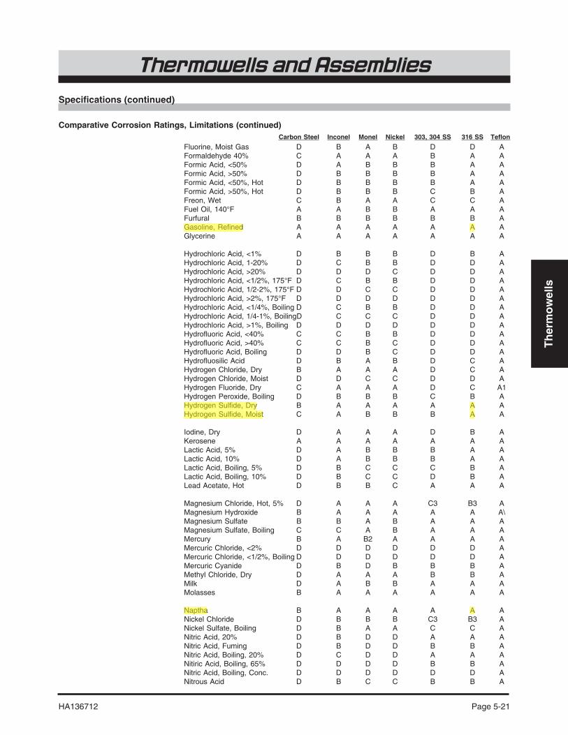
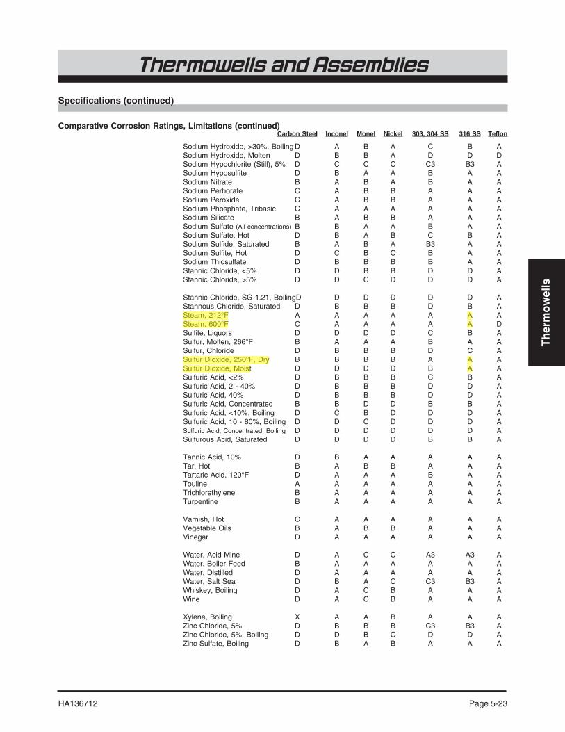
Comparative Corrosion Ratings, LimitationsThe data in this chart is reprinted with permission of Hoke, Inc., One Tenakill Park, Cresskill,New Jersey 07626.
This chart is a guide to the selection of a corrosion resistant protection tube. Changes intemperature, concentration, pressure, agitation, aeration and impurities can nullify theseratings. The only way to determine the suitability of a protection material in a media is byperformance tests. Mechanical strength of the protection tube must also be considered.Unless otherwise marked, all pressures and temperatures are atmospheric. This listing doesnot imply that other materials are not suitable for use in the media listed.
Trade Names Inconel, Monel .............................................................................. International Nickel Co.Teflon ............................................................................................................. E. I. DuPont
Ratings A ............................................. Substantial resistance. Preferred material of constructionB ................................ Moderate resistance. Satisfactory for use under most conditions.
Very slight swelling for elastomers.C................................................................... Questionable resistance. Use with caution.D................................................................... In adequate resistance. Not recommendedX .................................................................................................. No information available
Limitations 1 ..........................................................................................................................To 220°F2 ........... Subject to stress corrosion at high temperatures and in concentrated solutions3 ..Subject to pitting at air solution line when solution is allowed to dry on metal surface
Specifications (continued)
Carbon Steel Inconel Monel Nickel 303, 304 SS 316 SS Teflon

Th
erm
ow
ells
Thermowells and Assemblies
Page 5-20 HA136712
Barium Chloride, 5% C A A A A A ABarium Chloride, >5% Hot D B A A C3 B3 ABarium Hydroxide C A A A A A ABarium Nitrate C B C C A A ABeer, 160°F C A A A A A ABeet Sugar, Liquor, Hot B A A A A A ABenzene, Hot B A A A A A ABenzoic Acid B A A A A A ABlood D A A A A A A
Borax, Hot B A A B A A ABoric Acid, 5%, Hot D A B B B B ABromine, Dry Gas D B A A D D ABromine, Moist Gas D D C C D D AButtermilk D A A A A A AButyric Acid, Dilute X A A A A A AButyric Acid, Hot, Conc. D B B C C B A
Calcium Bisulfite, Hot D D D D C B ACalcium Chloride, Dilute C A A A B3 A3 ACalcium Hydroxide, 10% Boiling D A A A A A ACalcium Hydroxide, 20% Boiling D A A A A A ACalcium Hydroxide, 30% Boiling D A A A C B ACalcium Hypochloride, <2% C B C C C3 B3 ACarbolic Acid, 90% C A B A A A ACarbon Dioxide, Dry B A A A A A ACarbon Disulphide B A B B A A ACarbon Tetrachloride, Dry, Hot C A A A B A ACarbonic Acid, Saturated D A A A A A AChloroacetic Acid D B B B D C A
Chloric Acid D C C C D C AChlorinated Water, Sat. D C C C D C3 AChlorine, Dry Gas B A A A B B AChlorine, Moist Gas D D C C D C AChlorosulfonic Acid, Dilute D B B A D B AChromic Acid, Dilute B B B B B A AChromic Acid, <10% Boiling D C C D C B AChromic Acid, >10% Boiling D C D D D C ACitric Acid, Dilute D A A B A A ACitric Acid, Hot, Concentrated D B B B C B ACopper Nitrate, Hot, Concentr’d D C D D A A ACopper Sulfate, Hot, Concentr’d D B C C B A ACreosote, Hot B A A A A A ACupric Chloride, <2% D C B B B3 B3 ACupric Chloride, 5% D D D C D C3 A
Dichlorethane, Boiling D B A A B B AEthyl Chloride A A A A A A AEthylene Glycol A A A A A A A
Fatty Acids, 145°F C A A A B A AFerric Chloride, <1% D B C B C3 B3 AFerric Chloride, >1% D D D D D D AFerric Chloride, <1%, Boiling D D D D D D AFerric Chloride, >1%, Boiling D D D D D D AFerric Nitrate, 5% D C D D B A AFerric Sulfate, 5% D B C C B3 A AFerrous Sulfate, 10% C B A A A A AFluorine, Dry Gas C A A A C B AFluorine, Dry, 300°F D B A A D C D
Carbon Steel Inconel Monel Nickel 303, 304 SS 316 SS Teflon
Specifications (continued)
Comparative Corrosion Ratings, Limitations (continued)
Th
erm
ow
ells
HA136712 Page 5-21
Thermowells and Assemblies
Fluorine, Moist Gas D B A B D D AFormaldehyde 40% C A A A B A AFormic Acid, <50% D A B B B A AFormic Acid, >50% D B B B B A AFormic Acid, <50%, Hot D B B B B A AFormic Acid, >50%, Hot D B B B C B AFreon, Wet C B A A C C AFuel Oil, 140°F A A B B A A AFurfural B B B B B B AGasoline, Refined A A A A A A AGlycerine A A A A A A A
Hydrochloric Acid, <1% D B B B D B AHydrochloric Acid, 1-20% D C B B D D AHydrochloric Acid, >20% D D D C D D AHydrochloric Acid, <1/2%, 175°F D C B B D D AHydrochloric Acid, 1/2-2%, 175°F D D C C D D AHydrochloric Acid, >2%, 175°F D D D D D D AHydrochloric Acid, <1/4%, Boiling D C B B D D AHydrochloric Acid, 1/4-1%, BoilingD C C C D D AHydrochloric Acid, >1%, Boiling D D D D D D AHydrofluoric Acid, <40% C C B B D D AHydrofluoric Acid, >40% C C B C D D AHydrofluoric Acid, Boiling D D B C D D AHydrofluosilic Acid D B A B D C AHydrogen Chloride, Dry B A A A D C AHydrogen Chloride, Moist D D C C D D AHydrogen Fluoride, Dry C A A A D C A1Hydrogen Peroxide, Boiling D B B B C B AHydrogen Sulfide, Dry B A A A A A AHydrogen Sulfide, Moist C A B B B A A
Iodine, Dry D A A A D B AKerosene A A A A A A ALactic Acid, 5% D A B B B A ALactic Acid, 10% D A B B B A ALactic Acid, Boiling, 5% D B C C C B ALactic Acid, Boiling, 10% D B C C D B ALead Acetate, Hot D B B C A A A
Magnesium Chloride, Hot, 5% D A A A C3 B3 AMagnesium Hydroxide B A A A A A A\Magnesium Sulfate B B A B A A AMagnesium Sulfate, Boiling C C A B A A AMercury B A B2 A A A AMercuric Chloride, <2% D D D D D D AMercuric Chloride, <1/2%, Boiling D D D D D D AMercuric Cyanide D B D B B B AMethyl Chloride, Dry D A A A B B AMilk D A B B A A AMolasses B A A A A A A
Naptha B A A A A A ANickel Chloride D B B B C3 B3 ANickel Sulfate, Boiling D B A A C C ANitric Acid, 20% D B D D A A ANitric Acid, Fuming D B D D B B ANitric Acid, Boiling, 20% D C D D A A ANitiric Acid, Boiling, 65% D D D D B B ANitric Acid, Boiling, Conc. D D D D D D ANitrous Acid D B C C B B A
Carbon Steel Inconel Monel Nickel 303, 304 SS 316 SS Teflon
Specifications (continued)
Comparative Corrosion Ratings, Limitations (continued)

Th
erm
ow
ells
Thermowells and Assemblies
Page 5-22 HA136712
Oxalic Acid, <10% C A A A A A AOxalic Acid, 10% C A A A A A AOxalic Acid, Boiling, 10% D A A B D C AOxalic Acid, Boiling, 50% D B B C D C A
Phosphoric Acid (Ortho), <10% D A B B B A APhosphoric Acid (Ortho), 10-50% D A B C C A APhosphoric Acid (Ortho). >50% D A B C C A APhosphoric Acid (Ortho), <20%,175°F D C B D D A APhosphoric Acid (Ortho), >20%,175°F D D B D D B APhosphoric Acid (Ortho),10%, Boiling D D C D D B APhosphoric Acid (Ortho), 85%,Boiling D D D D D C APicric Acid C D D D A A APotassium Bromide D A A A C3 B3 APotassium Carbonate B A A A A A APotassium Chlorate B A B B A A APotassium Chloride D A A B A3 A3 APotassium Chloride, Hot D B A B C3 B3 APotassium Cyanide B B B B B B APotassium Dichromate, Conc. C B B C A A APotassium Ferricyanide, 5% C B B B A A APotassium Ferrocyandie, 5% C X B B A A APotassium Hydroxide, 50% B A A A A A APotassium Hydroxide, 30%, 175°F D A A A A A APotassium Hydroxide, 50%, 175°F D A A A B A APotassium Hydroxide, 30%, Boiling D A A A B A APotassium Hydroxide, 50%, Boiling D A A A B A APotassium Hypochlorite, Dilute D X D C C3 B3 APotassium Permanganate, Dilute B B A A A A APotassium Sulfate, Dilute B A A A A A APotassium Sulfate, Dilute, Boiling D B B B B B APotassium Sulfide, Saturated C A C A A A A
Propane, Liquid and Gas B A A A A A APyrogalic Acid B B A A A A A
Rosin, Molten D A A A A A A
Salicylic Acid D B B B B B ASilver Bromide D C B C B3 A3 ASilver Chloride D C B C D D ASilver Nitrate X A C D A A ASodium Acetate C A A A A A ASodium Bisulfate D B A B B B ASodium Bisulfate, 140°F D C B C B B ASodium Bromide, Dilute X B A B B3 A3 ASodium Carbonate, 5%, Hot B A A A A A ASodium Chloride, Dilute C A A A A A ASodium Chloride, Saturated, Boiling D A A A C3 B3 ASodium Cyanide B B A B B B ASodium Fluoride, 5% D B A A B3 A3 ASodium Hydroxide, 50% B A A A A A ASodium Hydroxide, <40%,175°F D A A A A A ASodium Hydroxide,40-80%,175°F D A A A A A ASodium Hydroxide, <30%, Boiling D A B A A A A
Carbon Steel Inconel Monel Nickel 303, 304 SS 316 SS Teflon
Specifications (continued)
Comparative Corrosion Ratings, Limitations (continued)
Th
erm
ow
ells
HA136712 Page 5-23
Thermowells and Assemblies
Sodium Hydroxide, >30%, Boiling D A B A C B ASodium Hydroxide, Molten D B B A D D DSodium Hypochlorite (Still), 5% D C C C C3 B3 ASodium Hyposulfite D B A A B A ASodium Nitrate B A B A B A ASodium Perborate C A B B A A ASodium Peroxide C A B B A A ASodium Phosphate, Tribasic C A A A A A ASodium Silicate B A B B A A ASodium Sulfate (All concentrations) B B A A B A ASodium Sulfate, Hot D B A B C B ASodium Sulfide, Saturated B A B A B3 A ASodium Sulfite, Hot D C B C B A ASodium Thiosulfate D B B B B A AStannic Chloride, <5% D D B B D D AStannic Chloride, >5% D D C D D D A
Stannic Chloride, SG 1.21, BoilingD D D D D D AStannous Chloride, Saturated D B B B D B ASteam, 212°F A A A A A A ASteam, 600°F C A A A A A DSulfite, Liquors D D D D C B ASulfur, Molten, 266°F B A A A B A ASulfur, Chloride D B B B D C ASulfur Dioxide, 250°F, Dry B B B B A A ASulfur Dioxide, Moist D D D D B A ASulfuric Acid, <2% D B B B C B ASulfuric Acid, 2 - 40% D B B B D D ASulfuric Acid, 40% D B B B D D ASulfuric Acid, Concentrated B B D D B B ASulfuric Acid, <10%, Boiling D C B D D D ASulfuric Acid, 10 - 80%, Boiling D D C D D D ASulfuric Acid, Concentrated, Boiling D D D D D D ASulfurous Acid, Saturated D D D D B B A
Tannic Acid, 10% D B A A A A ATar, Hot B A B B A A ATartaric Acid, 120°F D A A A B A ATouline A A A A A A ATrichlorethylene B A A A A A ATurpentine B A A A A A A
Varnish, Hot C A A A A A AVegetable Oils B A B B A A AVinegar D A A A A A A
Water, Acid Mine D A C C A3 A3 AWater, Boiler Feed B A A A A A AWater, Distilled D A A A A A AWater, Salt Sea D B A C C3 B3 AWhiskey, Boiling D A C B A A AWine D A C B A A A
Xylene, Boiling X A A B A A AZinc Chloride, 5% D B B B C3 B3 AZinc Chloride, 5%, Boiling D D B C D D AZinc Sulfate, Boiling D B A B A A A
Carbon Steel Inconel Monel Nickel 303, 304 SS 316 SS Teflon
Specifications (continued)
Comparative Corrosion Ratings, Limitations (continued)

Th
erm
ow
ells
Thermowells and Assemblies
Page 5-24 HA136712