Embed Size (px)
Citation preview

Data sheet
Thermostatically operatedcooling water valves
Types AVTA and FJVA
DKACV.PD.500.D1.32520B0131
March 2000
2 DKACV.PD.500.D1.32 Danfoss A/S 03-2000
Thermostatically operated cooling water valves
Types AVTA and FJVA

3DKACV.PD.500.D1.32 Danfoss A/S 03-2000
Thermostatically operated cooling water valves
Types AVTA and FJVA
Intoduction Thermostatically controlled valves are usedfor the infinite proportional regulation of flowquantities, depending on the setting and thesensor temperature.
The Danfoss range of thermostatic valvesincludes a series of industrial products forboth refrigeration and heating regulation. Thevalves are self-acting, i.e. they operatewithout a supply of auxiliary energy such aselectricity or compressed air.
Because the valves constanly match flowquantity to demand they are especiallysuitable for temperature regulation.
The required temperature is maintainedconstant with no overconsumption of - coolingwater in cooling systems - hot water or steamin heating systems Thus operating economyand effenciency is maximized.
AVTB for heat regulation 1/2" → 1"AVTA for cooling regulation 1/2" → 1"IVT for heat regulation 1/2" → 2"WVTS for cooling regulation 1 1/4" → 4"
For futher information please contactDanfoss.
Technical data
General
Thermostatic valves consist of three main elements.
Fig. 1Setting section with knob, closing andsetting scale.
Fig. 2Valve body with orifice, closing coneand sealing elements.
Fig. 3Hermetically sealed thermostatic elementwith sensor, bellows and charge
FunctionWhen the three elements are built togetherand the sensor is located at the point wherethe temperature is to be regulated, thefunction sequence is as follows:
1. A temperature-dependent pressure −charge vapour pressure − builds up in thesensor.
2. This pressure is transferred to the valvevia the capillary tube and bellows and actsas an opening or closing force.
3. The knob on the setting section and thespring exert a force that acts counter tothe bellows.
4. When balance is created between the twoopposing forces the valve spindle remainsin its position.
5. If the sensor temperature − or the setting −is changed, the point of balance becomesdisplaced and the valve spindle movesuntil balance is re-established, or the valveis fully open or closed.
6. On sensor temperature change theflow quantity change is approximatelyproportional.
The illustrations show an AVTA cooling watervalve, but the function principle applies to alltypes of thermostatic valves.
4 DKACV.PD.500.D1.32 Danfoss A/S 03-2000
Thermostatically operated cooling water valves
Types AVTA and FJVA
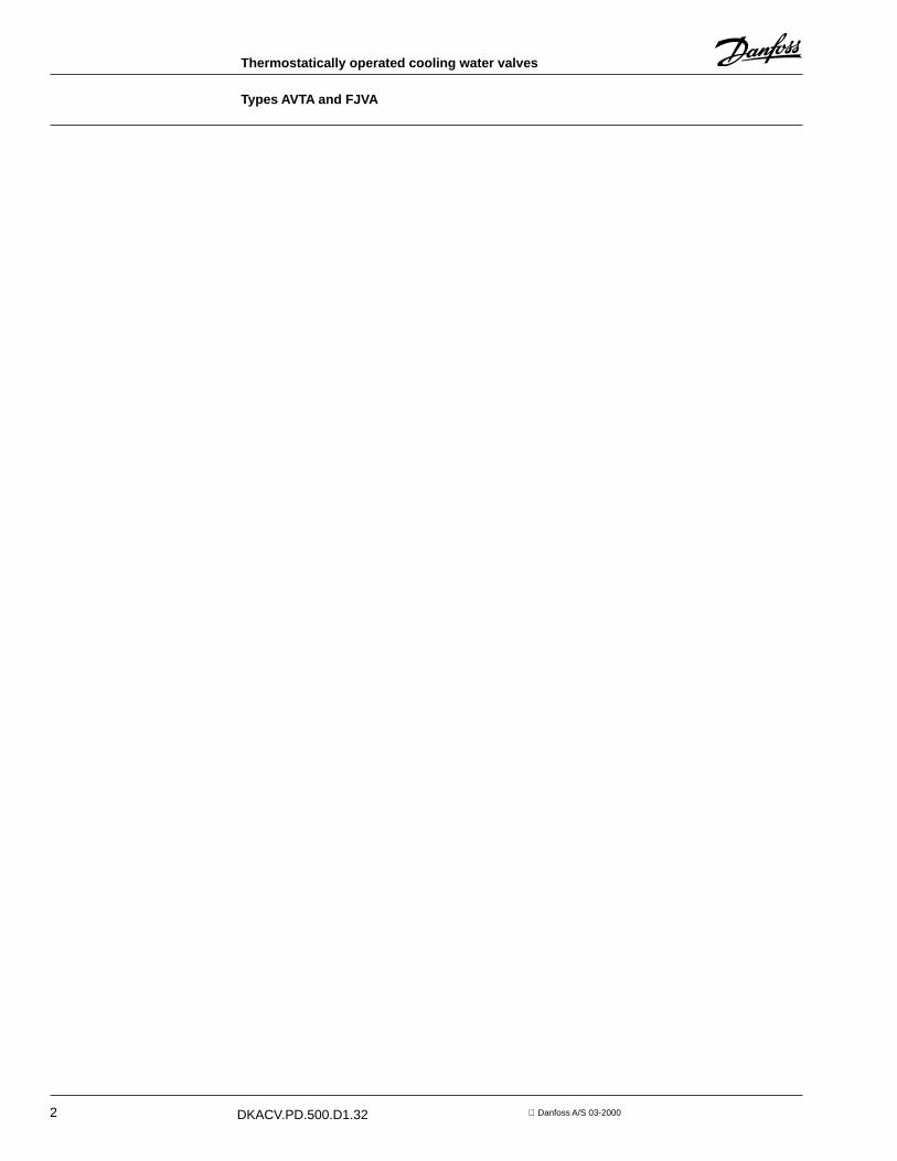
Application AVTA Self-acting AVTA cooling water valves arewidely used for temperature regulation inmany different machines and installationswhere cooling is required. AVTA always opensto admit flow on rising sensor temperature.The valve can be installed either in the coolingwater flow line or return line.
Typical application areas• Injection moulding machines• Compressors• Vacuum pumps• Dry cleaning machines• Distillashon plants• Printing machines• Hydraulic systems• Rollers/mills
1. Oil tank2. Hydraulic machinery3. Heat exchangers4. Cooiing water supply5. Cooling water valve type AVTA
Specifications andproducts
• Opens on rising sensor temperature• Media temperature −13° → +266 °F• Differential pressure 0 → 145 Psi• Max. test pressure 362 Psi
• Max. working pressure 232 Psi• The valves are pressure-relieved, i.e.
the degree of opening is not affected bydifferenhal pressure ∆p (pressure drop).
No. Description Material4 Spindle Brass(DIN 17660)W.No.204015 Diaphragms Ethylene-propylene-rubber(EPDM)7 Valve body and other parts Forged brass(DIN 17660)W.No.2.04028 Valve cone Nitrile rubber (NBR)9 Valve seat Stainless steel (DIN 17440)W.No.1.4305
12 Sensor Copper(DIN 1787)W.No.2.0090
13 Capillary tube gland Nitrile rubber(NBR),Brass DEN 17660W.No. 2.0321 og W.No.2.0401
AVTA valves are available with three different types of charge.
Fig. 4
Fig. 5AVTA
A. Adsorption chargeB. Mass chargeC. Universal charge
5DKACV.PD.500.D1.32 Danfoss A/S 03-2000
Thermostatically operated cooling water valves
Types AVTA and FJVA
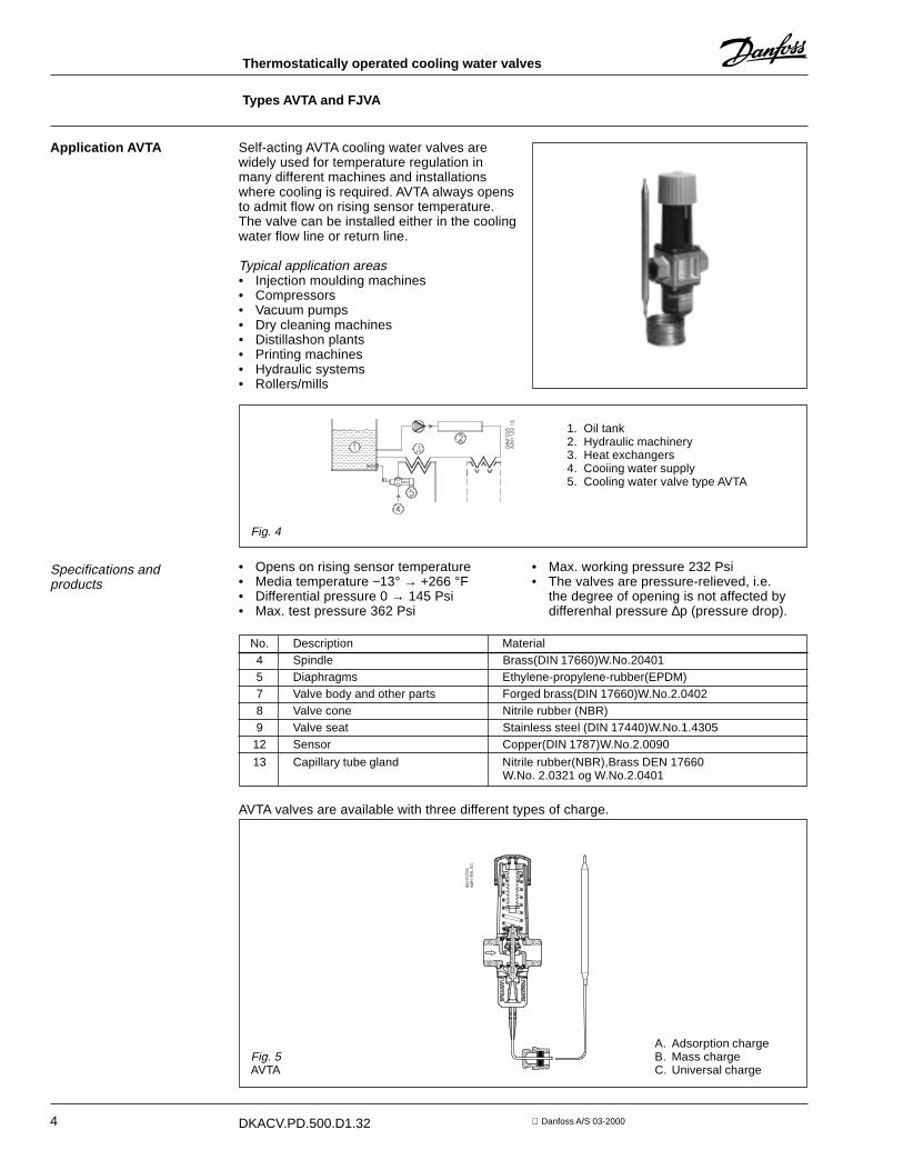
1/2"- 14 2.2 AVTA 15 003N61153/4"- 14 50 - 176 4.0 7' 6" AVTA 20 003N7120
1"- 11 1/2 6.4 AVTA 25 003N8125
AVTA withadsorption charge
The charge consists of active carbon and CO2which are absorbed or absorbed on rising orfalling sensor temperature and produce pres-sure changes in the element.
Special characteristics• Can be installed in any position.• Withstands up to
266 °F sensor temperature• Small sensor dimensions - 0.4" × 6.3"• Max. pressure on sensor 362 Psi
Cv-value
US gpm
Regulatingrange
°F
Capillary tubelength
Ft.Type Code no.
Connection
NPT
Code no. covers complete value incl. capillary tube gland, sensor pockets, see "Accessories"
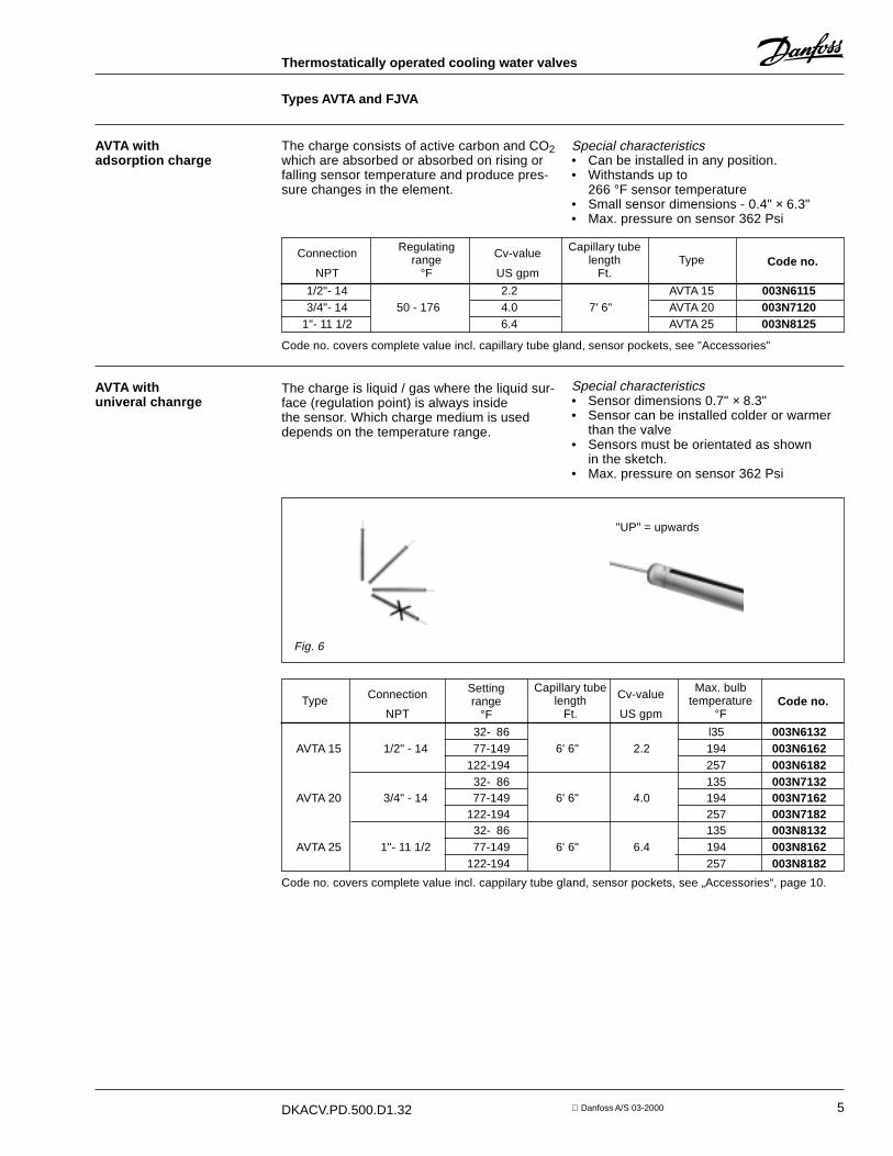
AVTA withuniveral chanrge
The charge is liquid / gas where the liquid sur-face (regulation point) is always insidethe sensor. Which charge medium is useddepends on the temperature range.
Special characteristics• Sensor dimensions 0.7" × 8.3"• Sensor can be installed colder or warmer
than the valve• Sensors must be orientated as shown
in the sketch.• Max. pressure on sensor 362 Psi
Fig. 6
"UP" = upwards
Code no.Capillary tube
lengthFt.
Cv-value
US gpm
Connection
NPTType
Settingrange
°F
Max. bulbtemperature
°F32- 86 l35 003N6132
AVTA 15 1/2" - 14 77-149 6' 6" 2.2 194 003N6162122-194 257 003N618232- 86 135 003N7132
AVTA 20 3/4" - 14 77-149 6' 6" 4.0 194 003N7162122-194 257 003N718232- 86 135 003N8132
AVTA 25 1"- 11 1/2 77-149 6' 6" 6.4 194 003N8162122-194 257 003N8182
Code no. covers complete value incl. cappilary tube gland, sensor pockets, see „Accessories“, page 10.

6 DKACV.PD.500.D1.32 Danfoss A/S 03-2000
Thermostatically operated cooling water valves
Types AVTA and FJVA
AVTA with mass charge The charge is liquid/gas.Because of thevolumenetric conditions the liquid surface(regulation point) can be either in the sensoror the bellows, depending on the temperatureconditions.
Special caracteristics:• Small sensor dimensions −0.4" × 7.5"• Short time constant• Sensor must always be installed warmer
than the valve• Max. pressure on sensor 362 Psi
For further information please contactDanfoss.
Fig. 7
Application FJVA F1VA valves are for applications where,because of installation problems, etc. it isdesirable to avoid using capillary tube. Thisapplies mainly where regulation accuracyrequirements are more moderate and wherean integral bypass can be accepted.In FJVA the whole bellows element is usedas the sensor. The valve reacts against thecooling water temperature and therefore itmust always be installed in the return line.Thus, indirect regulation is involved. Valves ofthis type operate with significantly longer timeconstants than AVTA valves where the sensoris located at the point at which the tempera-ture is to be regulated.FJVA is mainly used in systems where largeand sudden load changes do not occur.
For further information please contactDanfoss.
Fig. 8FJVA
Sizing When sizing and selecting a thermostaticvalve, the most important point is to ensurethat irrespective of the load the valve willalways give the necessary quantity of coolingwater. To be able to select a suitable size ofvalve, a necessary precondition is thatinformation on the cooling effect is available.On the other hand, the valve must not be toolarge, otherwise there will be a risk ofunstable regulation(hunting) .
The choise of charge is based on the tem-perature to be maintained, and on anassessment of the characteristics of theindividual types, as previously described.
In general, the aim must be to select thesmallest valve capable of ensuringadequate flow.
A futher recommandation is that thetemperature range be selected so that therequired sensor temperature lies at rangemid-point.
To enable fine adjustment of the valve, athermometer should be installed near thesensor.
7DKACV.PD.500.D1.32 Danfoss A/S 03-2000
Thermostatically operated cooling water valves
Types AVTA and FJVA
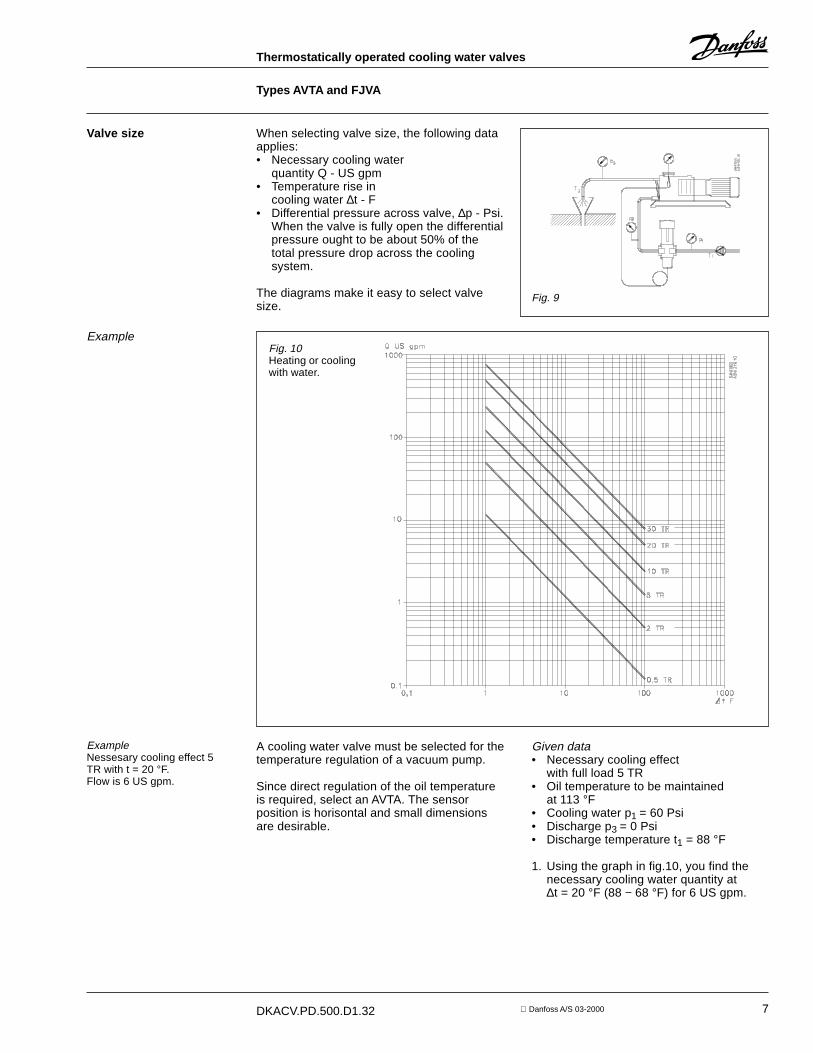
Valve size When selecting valve size, the following dataapplies:• Necessary cooling water
quantity Q - US gpm• Temperature rise in
cooling water ∆t - F• Differential pressure across valve, ∆p - Psi.
When the valve is fully open the differentialpressure ought to be about 50% of thetotal pressure drop across the coolingsystem.
The diagrams make it easy to select valvesize.
Fig. 9
Example
ExampleNessesary cooling effect 5TR with t = 20 °F.Flow is 6 US gpm.
A cooling water valve must be selected for thetemperature regulation of a vacuum pump.
Since direct regulation of the oil temperatureis required, select an AVTA. The sensorposition is horisontal and small dimensionsare desirable.
Given data• Necessary cooling effect
with full load 5 TR• Oil temperature to be maintained
at 113 °F• Cooling water p1 = 60 Psi• Discharge p3 = 0 Psi• Discharge temperature t1 = 88 °F
1. Using the graph in fig.10, you find thenecessary cooling water quantity at∆t = 20 °F (88 − 68 °F) for 6 US gpm.
Fig. 10Heating or coolingwith water.
8 DKACV.PD.500.D1.32 Danfoss A/S 03-2000
Thermostatically operated cooling water valves
Types AVTA and FJVA
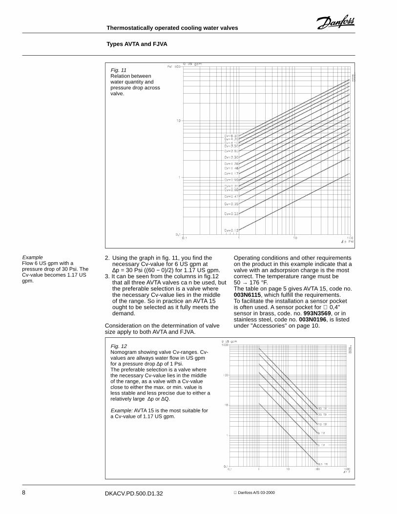
ExampleFlow 6 US gpm with apressure drop of 30 Psi. TheCv-value becomes 1.17 USgpm.
2. Using the graph in fig. 11, you find thenecessary Cv-value for 6 US gpm at∆p = 30 Psi ((60 − 0)/2) for 1.17 US gpm.
3. It can be seen from the columns in fig.12that all three AVTA valves ca n be used, butthe preferable selection is a valve wherethe necessary Cv-value lies in the middleof the range. So in practice an AVTA 15ought to be selected as it fully meets thedemand.
Consideration on the determination of valvesize apply to both AVTA and FJVA.
Fig. 12Nomogram showing valve Cv-ranges. Cv-values are allways water flow in US gpmfor a pressure drop ∆p of 1 Psi.The preferable selection is a valve wherethe necessary Cv-value lies in the middleof the range, as a valve with a Cv-valueclose to either the max. or min. value isless stable and less precise due to either arelatively large ∆p or ∆Q.
Example: AVTA 15 is the most suitable fora Cv-value of 1.17 US gpm.
Operating conditions and other requirementson the product in this example indicate that avalve with an adsorpsion charge is the mostcorrect. The temperature range must be50 → 176 °F.The table on page 5 gives AVTA 15, code no.003N6115, which fulfill the requirements.To facilitate the installation a sensor pocketis often used. A sensor pocket for ∅ 0,4"sensor in brass, code. no. 993N3569, or instainless steel, code no. 003N0196, is listedunder "Accessories" on page 10.
Fig. 11Relation betweenwater quantity andpressure drop acrossvalve.
9DKACV.PD.500.D1.32 Danfoss A/S 03-2000
Thermostatically operated cooling water valves
Types AVTA and FJVA
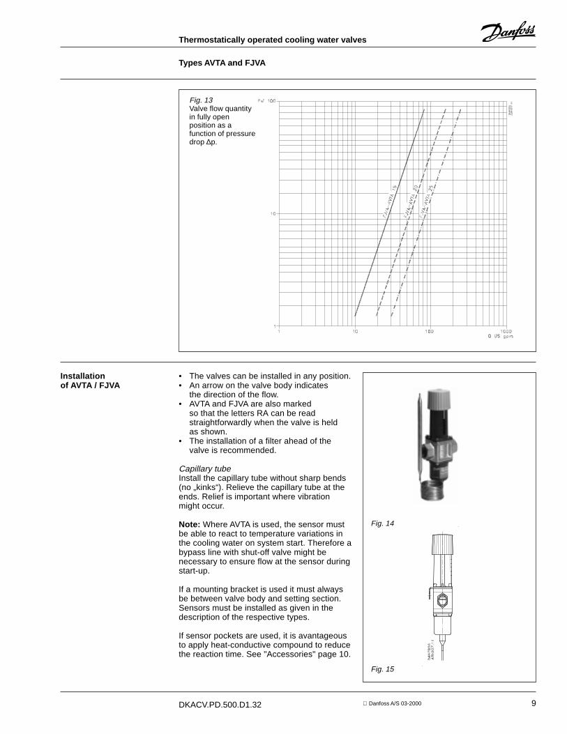
Fig. 13Valve flow quantityin fully openposition as afunction of pressuredrop ∆p.
Installationof AVTA / FJVA
• The valves can be installed in any position.• An arrow on the valve body indicates
the direction of the flow.• AVTA and FJVA are also marked
so that the letters RA can be readstraightforwardly when the valve is heldas shown.
• The installation of a filter ahead of thevalve is recommended.
Capillary tubeInstall the capillary tube without sharp bends(no „kinks“). Relieve the capillary tube at theends. Relief is important where vibrationmight occur.
Note: Where AVTA is used, the sensor mustbe able to react to temperature variations inthe cooling water on system start. Therefore abypass line with shut-off valve might benecessary to ensure flow at the sensor duringstart-up.
If a mounting bracket is used it must alwaysbe between valve body and setting section.Sensors must be installed as given in thedescription of the respective types.
If sensor pockets are used, it is avantageousto apply heat-conductive compound to reducethe reaction time. See "Accessories" page 10.
Fig. 14
Fig. 15
10 DKACV.PD.500.D1.32 Danfoss A/S 03-2000
Thermostatically operated cooling water valves
Types AVTA and FJVA
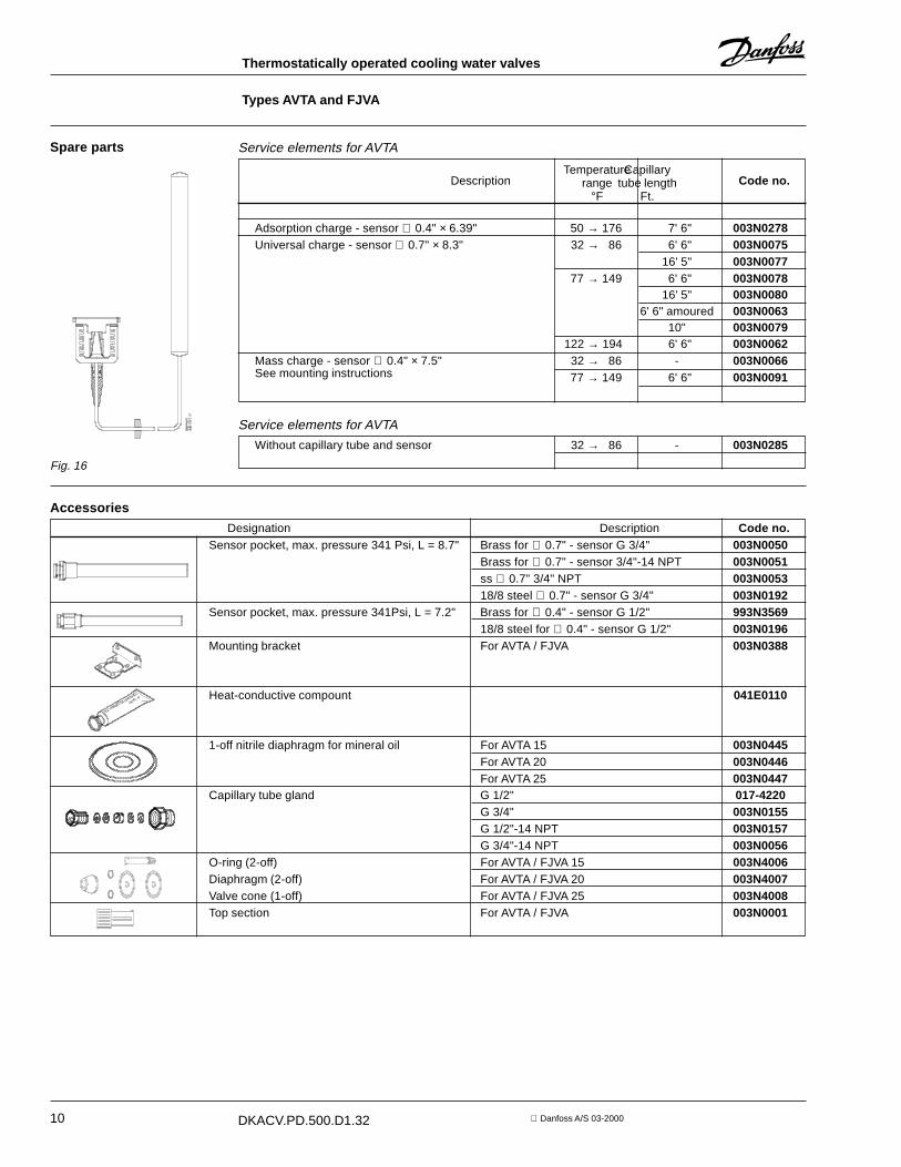
Spare parts Service elements for AVTA
Code no.DescriptionCapillary
tube lengthFt.
Temperaturerange
°F
Adsorption charge - sensor ∅ 0.4" × 6.39" 50 → 176 7' 6" 003N0278Universal charge - sensor ∅ 0.7" × 8.3" 32 → 86 6' 6" 003N0075
16' 5" 003N007777 → 149 6' 6" 003N0078
16' 5" 003N00806' 6" amoured 003N0063
10" 003N0079122 → 194 6' 6" 003N0062
Mass charge - sensor ∅ 0.4" × 7.5" 32 → 86 - 003N0066See mounting instructions 77 → 149 6' 6" 003N0091
Service elements for AVTA
Without capillary tube and sensor 32 → 86 - 003N0285
Fig. 16
Accessories
Designation Description Code no.Sensor pocket, max. pressure 341 Psi, L = 8.7" Brass for ∅ 0.7" - sensor G 3/4" 003N0050
Brass for ∅ 0.7" - sensor 3/4"-14 NPT 003N0051ss ∅ 0.7" 3/4" NPT 003N005318/8 steel ∅ 0.7" - sensor G 3/4" 003N0192
Sensor pocket, max. pressure 341Psi, L = 7.2" Brass for ∅ 0.4" - sensor G 1/2" 993N356918/8 steel for ∅ 0.4" - sensor G 1/2" 003N0196
Mounting bracket For AVTA / FJVA 003N0388
Heat-conductive compount 041E0110
1-off nitrile diaphragm for mineral oil For AVTA 15 003N0445For AVTA 20 003N0446For AVTA 25 003N0447
Capillary tube gland G 1/2" 017-4220G 3/4" 003N0155G 1/2"-14 NPT 003N0157G 3/4"-14 NPT 003N0056
O-ring (2-off) For AVTA / FJVA 15 003N4006Diaphragm (2-off) For AVTA / FJVA 20 003N4007Valve cone (1-off) For AVTA / FJVA 25 003N4008Top section For AVTA / FJVA 003N0001
11DKACV.PD.500.D1.32 Danfoss A/S 03-2000
Thermostatically operated cooling water valves
Types AVTA and FJVA
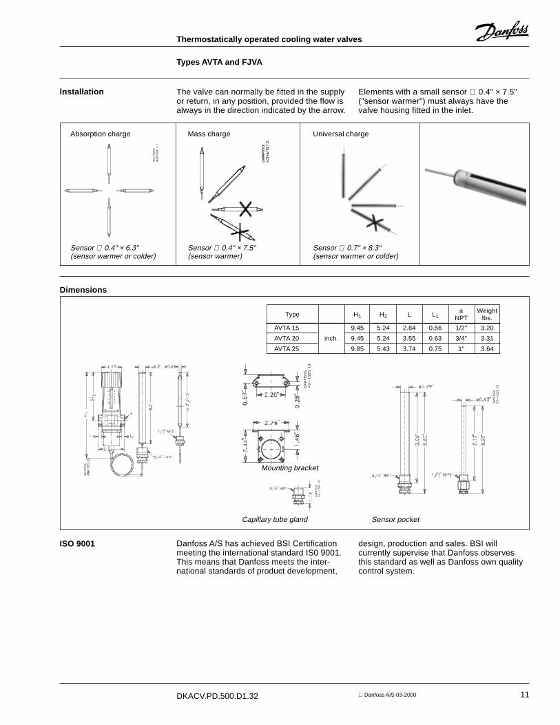
lnstallation The valve can normally be fitted in the supplyor return, in any position, provided the flow isalways in the direction indicated by the arrow.
Elements with a small sensor ∅ 0.4" × 7.5"("sensor warmer") must always have thevalve housing fitted in the inlet.
Dimensions
a WeightType H1 H2 L L1 NPT lbs.
AVTA 15 9.45 5.24 2.84 0.56 1/2" 3.20
AVTA 20 inch. 9.45 5.24 3.55 0.63 3/4" 3.31
AVTA 25 9.85 5.43 3.74 0.75 1" 3.64
Mounting bracket
Capillary tube gland Sensor pocket
ISO 9001 Danfoss A/S has achieved BSI Certificationmeeting the international standard IS0 9001.This means that Danfoss meets the inter-national standards of product development,
design, production and sales. BSI willcurrently supervise that Danfoss observesthis standard as well as Danfoss own qualitycontrol system.
Absorption charge Mass charge Universal charge
Sensor ∅ 0.4" × 6.3"(sensor warmer or colder)
Sensor ∅ 0.4" × 7.5"(sensor warmer)
Sensor ∅ 0.7" × 8.3"(sensor warmer or colder)
12 DKACV.PD.500.D1.32 Danfoss A/S 03-2000
Thermostatically operated cooling water valves
Types AVTA and FJVA
AC-VM/con