Embed Size (px)
Citation preview

HORNE
THERMOSTATIC CONTROL TECHNOLOGY
HORNE 40 AND 50 THERMOSTATIC MIXING SYSTEMS
APPLICATIONS
CONTROLLING TEMPERATURES IN; > hot water supplies distributed to groups of taps or showers, > domestic hot water supplies from large combination boilers. > hot water for process applications.
FEATURES
BENEFITS
ACCURACY OF TEMPERATURE CONTROL
MIXED WATER TEMPERATURE CONTROLLED OVER WITH ENORMOUS TURN DOWN RATIO
Rif RANGE OF FLOW RATES FROM ALL OUTLETS IN USE SIMULTANEOUSLY TO ONLY ONE OUTLET IN USE
MIXED WATER TEMPERATURE MAINTAINED WATER AT THE DESIRED TEMPERATURE IS ALWAYS WHEN NO OUTLETS ARE IN USE
AVAILABLE AT EVERY OUTLET
SUPPLIED AS AN ASSEMBLED PACKAGE
EASILY INSTAL I FD ON SITE WITH NO CHANCE OF MISTAKES
EASE OF MAINTENANCE
EASILY STRIPPED AND CLEANED WTTHOUT THE NEED FOR SPECIAL SKII I S OR TOOLS
RELIABILITY
MATERIALS OF CONSTRUCTION SPE-CIF1CALLY CHOSEN TO GIVE A TROUBLE FREE WORKING LIFE
SAFE AND COMFORTABLE HOT WATER TEMPERATURES Safe and comfortable hot water temperatures are typically 43-46°C for a bath and 33-411°C for a shower.
Domestic hot water, however, is normally stored at temperatures close to 60°C. Water, at this temperature, coming into contact with skin for 3 seconds, can result in a third degree burn.
The risk of injury can be eliminated by reducing the hot water temperature before it is distributed to outlets.
HORNE 40 and HORNE 50 Thermostatic Mixing Systems can reduce the temperature by mixing hot water with cold water to produce mixed water; at a temperature, which is controlled within safe and comfortable limits.
Distributing water at temperatures below 52°C would allow any legionella in it to multiply. There are water treatment processes available to combat legionella and any water should be treated if the users of it are considered to be at risk of contracting legionnaires' disease.
Domestic hot water supplies from combination boilers will normally be controlled at temperatures of 55°C to 60°C. If lower temperatures are required at some outlets, HORNE 15 or 20 TMVs could be installed to reduce the temperature to the desired level. To control the temperature at showers HORNE TSV1 Thermostatic Shower Valves can be used.

TECHNICAL INFORMATION
.F. {MAINTENANCE ACCESS}
14I NED WATER FLOW
M IXED WATER FIETUFt1
GOLD WATER SUPPLY
REILIRN TO CALORIFIER 1-11-1-
1K
J
12 2 4 6 a 10
80
70
60
50
40
30
20
10
FLO
W R
ATE
gpm
6
5
BALL FLOW FIDIGATORICH ECK VALVE
SIZE
40 1.1.12' 142 251 121 222 235 1' 114 1/2" 1/2'
50 2" 150 258 143 244 248 1' 130 1/2" 1/2'
RANGES OF TEMPERATURE ADJUSTMENT THE FOUR STANDARD RANGES ARE; 15°C to 32°C, 32°C to 52°C, 45°C to 62°C,
58°C to 80°C.
OPERATING CONDITIONS Maximum hot water supply temperature: 85°C
Minimum hat water
10°C above mixed supply temperature: water temperature
setting
Maximum cold water
10°C below mixed supply temperature: water temperature
setting
Maximum static pressure: 10 bar
Maximum pressure drop across HORNE TMV: 1.2 bar
Maximum recommended flow rates
HORNE 40 TMV: 4.5 Vs (270 l/min)
HORNE 50 TMV: 5.7 Vs (342 limin)
WRAS Approved: Certificate No. 0001076
SIZING CHART
PRESSURE DROP THRO' TMV mWG
The pressure drop across the HORNE TMV for any given flow rate can be easily estimated. For example, if the designed maximum mixed water flow rate is 3.511s the pressure drop across the TMV is found by reading across from 3.5 on the "y" axis to the points of intersection with the curves then down to the "x" axis. It will be seen that the pressure drops are; 7.4m WG for the HORNE 40 TMV and 4.7m WG for the HORNE 50 TIVV.

CHECK VALVE\
THERMOME I ER
MIXED WATER FLOW 45 C it 1
HORNE 40 OR 50 IM.V
MIXED WATER RETURN 43 C
HORNE THERMOSTATIC RETURN LIMITER
12 C COLD WATER SUPPLY -.4
BALL FLOW INDICATOR CHECK VALVE
CHECK VALVE
13_1-1W.S CALOR1FIER
43 G
■ HOW HORNE 40 AND 50 THERMOSTATIC MIXING SYSTEMS WORK
HOT WATER 60 C
HORNE THERMOSTATIC MIXING SYSTEMS (TMSs) have the ability to control mixed water temperatures when OUTLETS ARE IN USE and also when OUTLETS ARE NOT IN USE as follows.
WHEN OUTLETS ARE IN USE the HORNE TMV mixes hot water, from a calorifier, with cold water to deliver mixed water, at a chosen temperature, to a number of outlets. The flow rate through the HORNE TMV will vary, depending upon the demand, at the outlets. A specially designed by-pass arrangement. in the HORNE TMV, enables it to control the mixed water temperature, within safe and comfortable limits, over the full range of flow rates from all the outlets in use simultaneously right down to only ONE outlet in use.
Hot and cold water supply temperatures will normally vary, from time to time, throughout any 24 hour period. When these variations occur the HORNE TMV will compensate for them and will continue to control the mixed water temperature within safe and comfortable limits.
WHEN OUTLETS ARE NOT 1N USE and all the taps or showers are turned off, the mixed water is purely being circulated by pump round the pipework and its temperature will fall slightly due to pipework heat losses. To make up the losses, a small portion of the return water is sent back through the calorifier for reheating and is then mixed with the remainder of the return to bring the mixed water flow temperature back up to the desired level.
The HORNE THERMOSTATIC RETURN LIMITER (TRL), at the return connection to the HORNE TMV, controls the amount of return water sent back through the calorifier for reheating, to make up the heat losses.
If the return temperature tends to rise, the TRL tends to close and less water will be returned for reheating. Conversely if the return temperature tends to fall, the TRL will tend to open and more water will be returned for reheating,
In practice, the TRL adopts a throttling position and the portion of return water reheated, in the calorifier, is just sufficient to be mixed with the remainder of the return to bring the mixed water low temperature back up to the desired level.
The mixing of the two portions of return water takes place in the HORNE TMV but since the HORNE TRL controls the amount of water passed through the calorifier for reheating, it is in fact, the HORNE TRL which controls the mixed water flow temperature, when the outlets are not in use, and not the HORNE TMV.
A considerable benefit of this arrangement is that the thermostat element in the HORNE TMV is always immersed in water at the desired mixed water flow temperature, therefore, as soon as there is a demand at an outlet the HORNE TMV does not need to make a correction in temperature and there is no start up transient, as there is with a point of use TMV. The ball flow indicator gives a visual indication that the mixed water is circulating and that some of it is passing back to the calorlier. This indicator is essential during commissioning or adjusting the temperature setting on the HORNE TRL. It is also a check valve to prevent back flow from the calorifier.
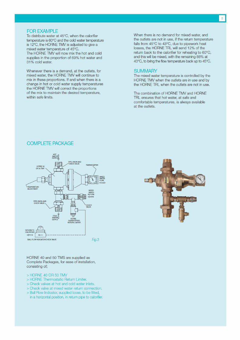
FOR EXAMPLE To distribute water at 45°C, when the calorifier temperature is 60°C and the cold water temperature is 12°C, the HORNE TMV is adjusted to give a mixed water temperature of 45°C. The HORNE TMV will now mix the hot and cold supplies in the proportion of 69% hot water and 31% cold water.
Whenever there is a demand, at the outlets, for mixed water, the HORNE TMV will continue to mix in these proportions. If and when there is a change in hot or cold water supply temperatures the HORNE TMV will correct the proportions of the mix to maintain the desired temperature, within safe limits.
When there is no demand for mixed water, and the outlets are not in use, if the return temperature falls from 45°C to 43°C, due to pipework heat losses, the HORNE TRL will send 12% of the return back to the calorifter for reheating to 60°C, and this will be mixed, with the remaining 88% at 43°C, to bring the flow temperature back up to 45°C.
SUMMARY The mixed water temperature is controlled by the HORNE TMV when the outlets are in use and by the HORNE TRL when the outlets are not in use.
The combination of HORNE TMV and HORNE TRL ensures that hot water, at safe and comfortable temperatures, is always available at the outlets.
COMPLETE PACKAGE
cT SUPPL
BALL
FLOW 14 1ALVE
HORNE 40 and 50 TMS are supplied as Complete Packages, for ease of installation, consisting of;
> HORNE 40 OR 50 TMV > HORNE Thermostatic Return Limiter. > Check valves at hot and cold water inlets. > Check valve at mixed water return connection. > Ball Row Indicator, supplied loose, to be fitted,
in a horizontal position, in return pipe to calortfier.

COLD WATER SERVICE
D.H WS. CALORIFIER
60 C
Hg.4 BALL FLOW /ND ICATOR/CHECK VALVE
MIXED WATER FLOW 45 C
MIXED WATER RETURN -g-
HORNE 40 OR 50 TMV
HORNE THERMOSTATIC RETURN LIMITER
COLD WATER SERNCE
MIXED WATER FLOW 45 C
HORNE 40 OR 56 TMV
-v- MIXED WATER RETURN
CALORIFIER
HORNE THERMOSTATIC RETURN LIMITER
PALL FLOW INDICATOR/CHECK VALVE
WATER
TREATM
UNIT
• TYPICAL APPLICATIONS
COLD WATER SUPPLY
APPLICATION 1 Using a HORNE TMS to reduce a DHWS flow temperature from 60°C to 45°C to prevent scalding and provide hot water at a number of outlets at a safe and comfortable temperature.
When the outlets are in use the HORNE TMV mixes hot water, from the calorifier, at 60°C with cold water at ambient temperature to produce mixed water at 45°C.
When the outlets are NOT in use the mixed water is circulated, by pump, to ensure that water, at the desired temperature, is always available at all of the outlets.
The HORNE THERMOSTATIC RETURN LIMITER controls the amount of return water passed back through the calorffier for re-heating to make up heat losses in the mixed water flow and return pipework.
COLD WATER SUPPLY
APPLICATION 2 Where there is a risk of the water being contaminated by legionella bacteria, treatment to kit the bacteria should be provided, as shown.

NORMAL TEMPERATURE DHWS FLOW 50 C
COLD WATER SEFMCE
114
MIXED WATER RETURN
Fg.
CALDRIFIER
so C
HORNE THERMOSTATIC RETURN LIMBER
BALL FLOW INDICATORCI-IECK VALVE
DI-WS RETURN
MIXED WATER FLOW 45 C
COLD
SUPPLY
CHECK VALVE
TEMPJPRESSURE RELIEF VALVE
HORNE 40 OR 50 TM.V_
HORNE THERMOSTATIC RETURN MITER
BALL FLEW INOICATOP/CHECKVALYE
HOT WATER
COMBINATION BOILER
B5 C
IXP'N. VESSEL
Fg.
MIXED WATER FLOA, 60 C
MIXED WATER RETURN
■
COLD WATER SUPPLY
APPLICATION 3 Using a HORNE TMS to reduce a DHWS flow temperature, from 60°C to 45°C, to some outlets, while other outlets are supplied with hot water at 60°C.
APPLICATION 4 Using a HORNE TMS to reduce the temperature in hot water from a combination boiler from 70-80°C to the normal DHWS flow temperature of 60°C.
PLEASE NOTE HORNE 40 and 50 TMSs can be installed in any attitude with the outlet pointing el the horcntal direction, as shown in the typical application sketches, or pointing vertically upwards or vertically downwards. The ball How indicator must be installed in a horontal pipe.
The four typical applications shown are only representative of the many applications for which HORNE 40 and 50 TMVs are suitable. We would be pleased to advise on specific applications.

HORNE ENGINEERING Ltd PO Box 7 Rankine Street Johnstone PA5 8BD United Kingdom tel +44 (0)1505 321455 fax +44 (0)1505 336287 email sales©horne.co.uk web www horne.co.uk


![Dixon Miniatures, Unit 24 Queens Square Business Park ... · Falcon 2pd1 gun Limber ECW33 ECW34 ECW35 ECWCII ECWC12 ECWH5 ECWTL] 2 Draught Horse Team with Driver, Limber & Falcon](https://img.pdfslide.us/doc/110x75/611633561d5f982f6c7c1119/dixon-miniatures-unit-24-queens-square-business-park-falcon-2pd1-gun-limber.jpg)