Embed Size (px)
Citation preview

Venstar Inc. 08/07
Meets Commercial California Title 24
Use with most Air Conditioning & Heating Systems including: 1 or 2 Stage Electric Cooling & 3 Stage Gas Heating, Heat Pump, Electric or Hydronic Heat.
HEATCOOL HEAT
PUMP
Digital Thermostat
PROGRAMMABLE
up to 3-heat& 2-cool
7-DAYDigital
Thermostat
PROGRAMMABLE
up to 3-heat& 2-cool
7-DAY
THERMOSTAT
T2800
commercial
Control up to 3 Heat &2 Cool Stages3 Configurable Outputs
Timers & DeadbandsBacklit Display & ButtonLegendsAux Heat IndicatorSet Point Limiting
Adjustable 2nd & 3rd Stage
Outdoor Sensor Ready withHigh/Low Readouts for the DayAccepts EZ ProgrammerAccepts Optional Humidity Module: Controls Humidificationand DehumidificationAccepts Optional IR Remote Control Accepts Comfort CallPhone Control Accessory
INSTALLATIONINSTRUCTIONSINSTALLATIONINSTRUCTIONS
Page i
NOTE: Due to variations in environmental conditions, it is not always possible to achieve the desired humidification or dehumidification setpoint.
MISC3 MISC3
OK
This device complies with Part 15 of the FCC Rules. Operation is subject to the following two conditions: (1) this device may not cause harmful interference, and (2) this device must accept any interference received, including interference that may cause undesired operation.
Follow the Installation Instructions before proceeding. Set the thermostat mode to “OFF” prior to changing settings in setup or restoring Factory Defaults.
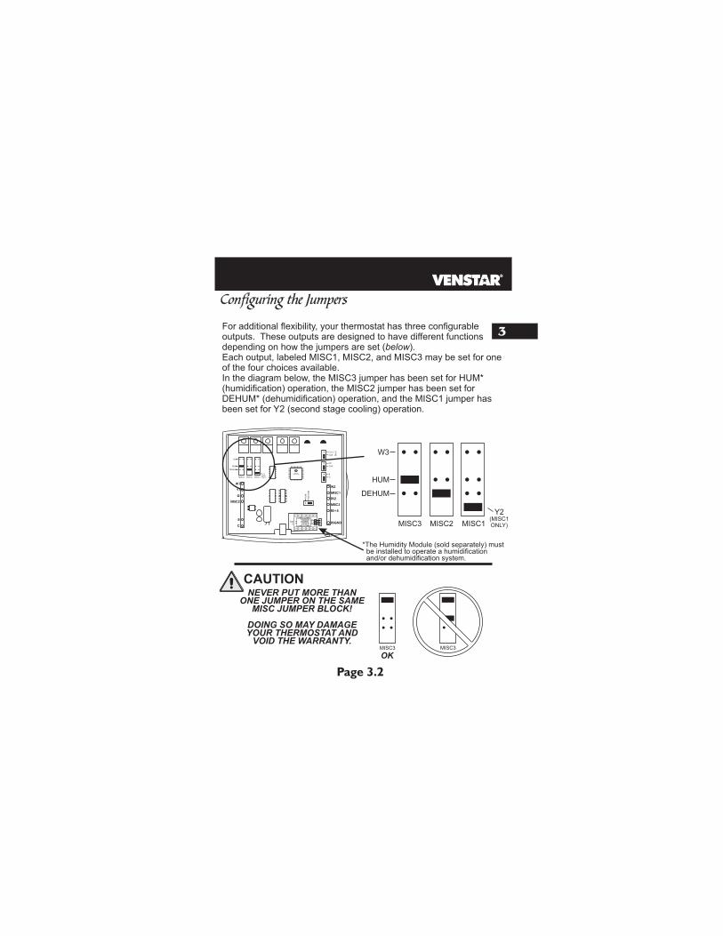
NEVER PUT MORE THAN ONE JUMPER ON THE SAME MISC JUMPER BLOCK!
THIS MAY DAMAGE YOUR THERMOSTAT AND VOID YOUR WARRANTY.
CAUTION
CcFFOR HOME OR OFFICE USE
Tested to Complywith FCC Standards
Thermostat T2800
4Z95
CAUTION

8
2
1
3
6
7
4
5
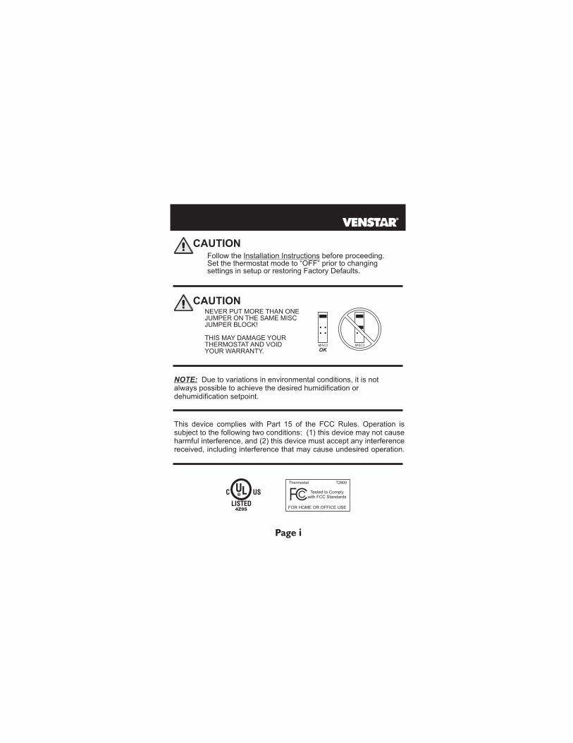
Preparation
Remove & Replace the Old ThermostatConfiguring the MISCOutputs
Sample Wiring Diagrams
Calibrating the Thermostat Sensors
Test Operation
TroubleShooting
Page iii
Table of Contents
Wire Connections
Page 1.1
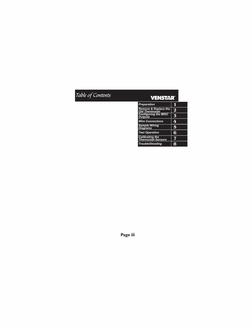
SECTION 1Preparation1
Assemble tools
Flat BladeScrewdriver
Wire cutter& Stripper
Make sure your Heater/Air Conditioner is working properly before beginning installation of the thermostat.
Carefully unpack the thermostat. Save the screws, bracket, and instructions.
Turn off the power to the Heating/Air Conditioning system at the main fuse panel. Most residential systems have a separate breaker for disconnectingpower to the furnace.
Proper installation of the thermostat will be accomplished by following these step by step instructions. If you are unsure about any of these steps, call a qualified technician for assistance.
AUTO
I2:00 Pm
HEAT
COOL
72
74
AUTO
I2:00 Pm
HEAT
COOL
72
74
AUTO
I2:00 Pm
HEAT
COOL
72
74
AUTO
I2:00 Pm
HEAT
COOL
72
74
AUTO
I2:00 Pm
HEAT
COOL
72
74
Page 2.1
SECTION 2Remove & Replace the Old Thermostat
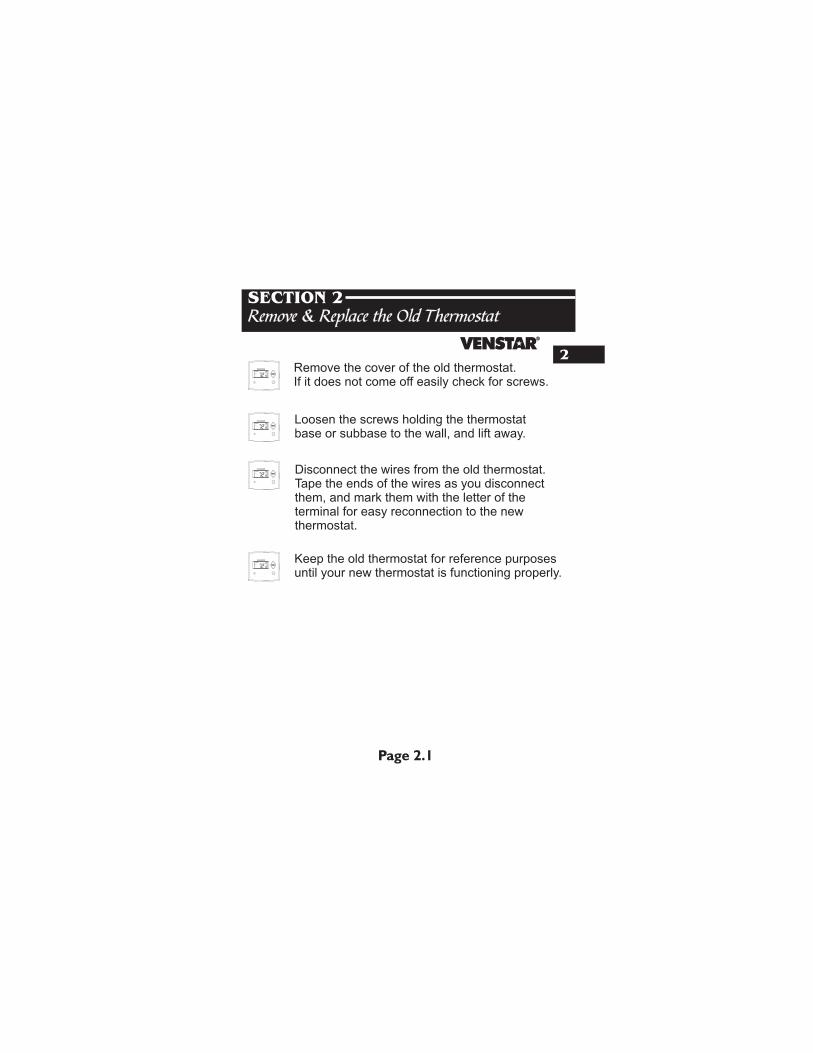
2Remove the cover of the old thermostat.If it does not come off easily check for screws.
Loosen the screws holding the thermostatbase or subbase to the wall, and lift away.
Disconnect the wires from the old thermostat. Tape the ends of the wires as you disconnect them, and mark them with the letter of the terminal for easy reconnection to the new thermostat.
Keep the old thermostat for reference purposes until your new thermostat is functioning properly.
AUTO
I2:00 Pm
HEAT
COOL
72
74
AUTO
I2:00 Pm
HEAT
COOL
72
74
AUTO
I2:00 Pm
HEAT
COOL
72
74
AUTO
I2:00 Pm
HEAT
COOL
72
74
3
Page 3.1
Section 3 Contents: Configuring the Jumpers........3.2
Explanation of Jumper
Settings..................................3.3
SECTION 3Configuring the MISC Outputs
3
Configuring the Jumpers
Page 3.2
For additional flexibility, your thermostat has three configurable outputs. These outputs are designed to have different functions depending on how the jumpers are set (below). Each output, labeled MISC1, MISC2, and MISC3 may be set for one of the four choices available.In the diagram below, the MISC3 jumper has been set for HUM* (humidification) operation, the MISC2 jumper has been set for DEHUM* (dehumidification) operation, and the MISC1 jumper has been set for Y2 (second stage cooling) operation.
NEVER PUT MORE THAN ONE JUMPER ON THE SAME
MISC JUMPER BLOCK!
DOING SO MAY DAMAGEYOUR THERMOSTAT AND
VOID THE WARRANTY.
W3
HUM
DEHUM
MISC3 MISC2 MISC1
Y2(MISC1ONLY)
CAUTION
MISC3 MISC3
OK
HP
GAS
B
O
ELEC
GAS
(FA
N)
W1
Y1
G
R
C
MISC2
W2
MISC1
RS2
RSGND
MISC3
RS+5
W3
HUM
DEHUM
MISC3 MISC2 MISC1
Y2(MISC1ONLY)
INSTALL HUMIDITY MODULE WITH SENSING
ELEMENT OUTWARD
HU
M
NO
HU
M
*The Humidity Module (sold separately) must be installed to operate a humidification and/or dehumidification system.
1
2 4 6 8 X Z
1 5 7 9 Y3
Page 3.3
3
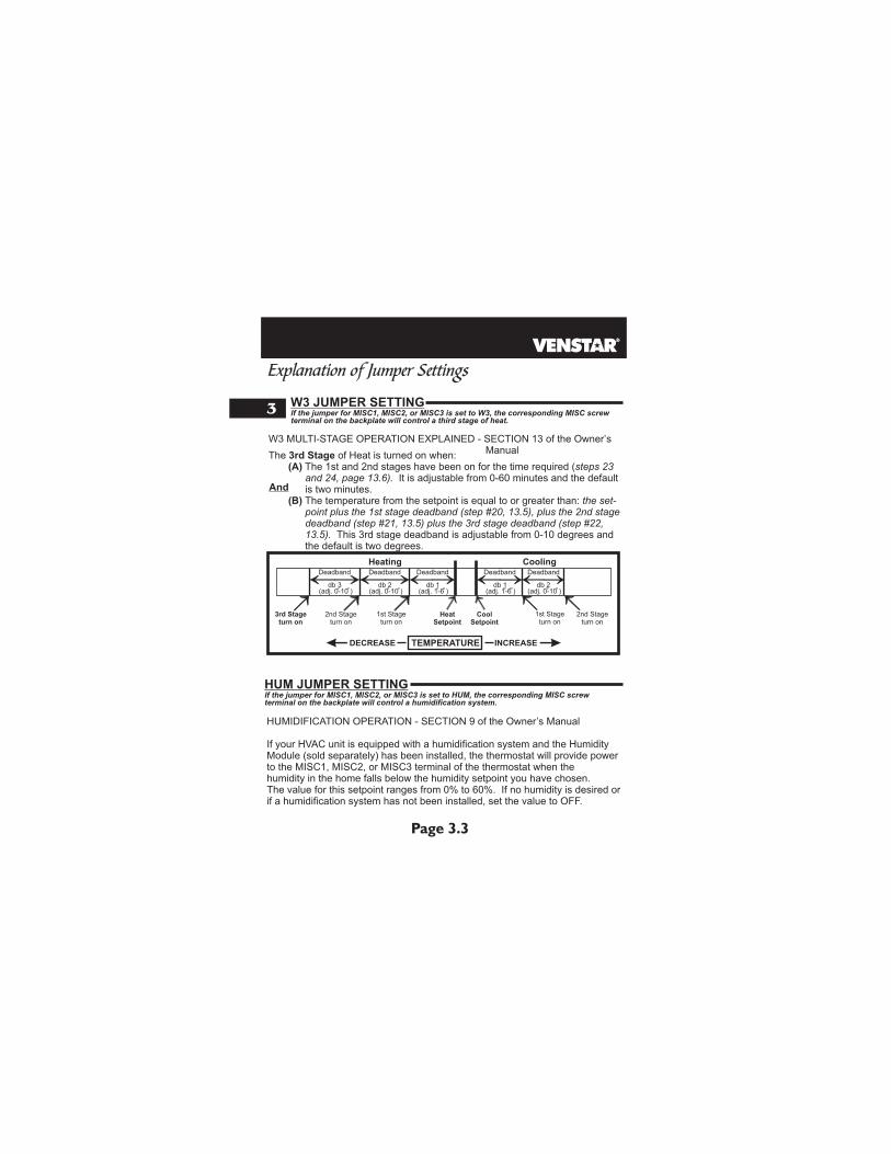
The 3rd Stage of Heat is turned on when: (A) The 1st and 2nd stages have been on for the time required (steps 23 and 24, page 13.6). It is adjustable from 0-60 minutes and the default is two minutes. (B) The temperature from the setpoint is equal to or greater than: the set- point plus the 1st stage deadband (step #20, 13.5), plus the 2nd stage deadband (step #21, 13.5) plus the 3rd stage deadband (step #22, 13.5). This 3rd stage deadband is adjustable from 0-10 degrees and the default is two degrees.
W3 JUMPER SETTINGIf the jumper for MISC1, MISC2, or MISC3 is set to W3, the corresponding MISC screw terminal on the backplate will control a third stage of heat.
Explanation of Jumper Settings
And
HeatSetpoint
CoolSetpoint
Deadband Deadband DeadbandDeadbandDeadband
db 1 db 1db 2 db 2db 3(adj. 1-6 )(adj. 0-10 )(adj. 0-10 ) (adj. 0-10 )(adj. 1-6 )
1st Stageturn on
2nd Stageturn on
3rd Stageturn on
1st Stageturn on
2nd Stageturn on
Heating Cooling
TEMPERATUREDECREASE INCREASE
W3 MULTI-STAGE OPERATION EXPLAINED - SECTION 13 of the Owner’s Manual
HUMIDIFICATION OPERATION - SECTION 9 of the Owner’s Manual
If your HVAC unit is equipped with a humidification system and the Humidity Module (sold separately) has been installed, the thermostat will provide power to the MISC1, MISC2, or MISC3 terminal of the thermostat when the humidity in the home falls below the humidity setpoint you have chosen. The value for this setpoint ranges from 0% to 60%. If no humidity is desired or if a humidification system has not been installed, set the value to OFF.
HUM JUMPER SETTINGIf the jumper for MISC1, MISC2, or MISC3 is set to HUM, terminal on the backplate will control a humidification system.
the corresponding MISC screw
Page 3.4
3DEHUM JUMPER SETTING
Explanation of Jumper Settings (continued)
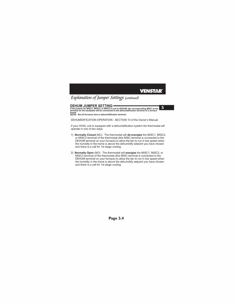
If the jumper for MISC1, MISC2, or MISC3 is set to DEHUM, terminal on the backplate will be connected to the dehumidification terminal of a furnace board.NOTE: Not all furnaces have a dehumidification terminal.
the corresponding MISC screw
DEHUMIDIFICATION OPERATION - SECTION 10 of the Owner’s Manual
If your HVAC unit is equipped with a dehumidification system the thermostat will operate in one of two ways.
1) Normally Closed (NC): The thermostat will de-energize the MISC1, MISC2, or MISC3 terminal of the thermostat (this MISC terminal is connected to the DEHUM terminal on your furnace) to allow the fan to run in low speed when the humidity in the home is above the dehumidify setpoint you have chosen and there is a call for 1st stage cooling.
2) Normally Open (NO): The thermostat will energize the MISC1, MISC2, or MISC3 terminal of the thermostat (this MISC terminal is connected to the DEHUM terminal on your furnace) to allow the fan to run in low speed when the humidity in the home is above the dehumidify setpoint you have chosen and there is a call for 1st stage cooling.
Page 3.5
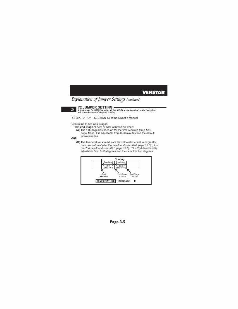
3Y2 JUMPER SETTINGIf the jumper for MISC1 is set to Y2 the will control a second stage of cooling.
MISC1 screw terminal on the backplate
Y2 OPERATION - SECTION 13 of the Owner’s Manual
Control up to two Cool stages. The 2nd Stage of heat or cool is turned on when: (A) The 1st Stage has been on for the time required (step #23, page 13.6). It is adjustable from 0-60 minutes and the default is two minutes. (B) The temperature spread from the setpoint is equal to or greater than: the setpoint plus the deadband (step #24, page 13.6), plus the 2nd deadband (step #21, page 13.5). This 2nd deadband is adjustable from 0-10 degrees and the default is two degrees.
Explanation of Jumper Settings (continued)
And
CoolSetpoint
DeadbandDeadband
db 1 db 2(adj. 0-10 )(adj. 1-6 )
1st Stageturn on
2nd Stageturn on
Cooling
TEMPERATURE INCREASE
Page 4.1
SECTION 4Wire Connections
4
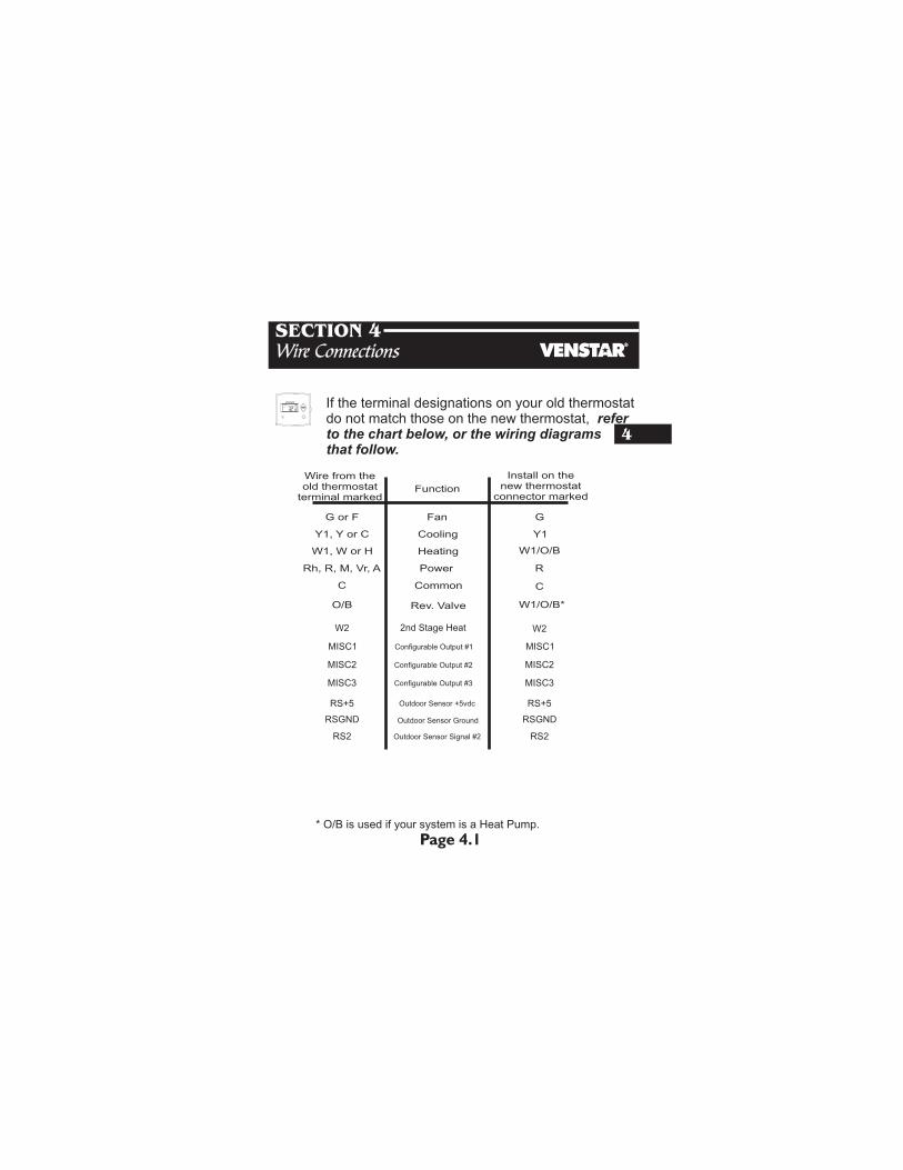
If the terminal designations on your old thermostat do not match those on the new thermostat, refer to the chart below, or the wiring diagrams that follow.
* O/B is used if your system is a Heat Pump.
Wire from theold thermostat
terminal markedFunction
Install on thenew thermostat
connector marked
G or F Fan G
Y1, Y or C Cooling Y1
W1, W or H Heating W1/O/B
PowerRh, R, M, Vr, A R
C
O/B
C Common
Rev. Valve
W2 2nd Stage Heat
RS+5 Outdoor Sensor +5vdc RS+5
RSGND Outdoor Sensor Ground RSGND
W1/O/B*
W2
MISC1
MISC2
MISC3
MISC1
MISC2
MISC3
Configurable Output #1
Configurable Output #2
Configurable Output #3
RS2 RS2Outdoor Sensor Signal #2
AUTO
I2:00 Pm
HEAT
COOL
72
74
Page 5.1
Section 5 Contents: HVAC Equipment Wiring............5.2
MISC1, MISC2, and MISC3
Wiring........................................5.6
Installing the Outdoor Sensor...5.8
SECTION 5Sample Wiring Diagrams
5
HP
GAS
B
O
ELEC
GAS
(FA
N)
W1
Y1
G
R
C
MISC2
W2
MISC1
RS2
RSGND
MISC3
RS+5
W3
HUM
DEHUM
MISC3 MISC2 MISC1
Y2(MISC1ONLY)
INSTALL HUMIDITY MODULE WITH SENSING
ELEMENT OUTWARD
HU
M
NO
HU
M
Y1G
RC
MISC2
W1/O/BMISC1
RS+5
RSGND
W2
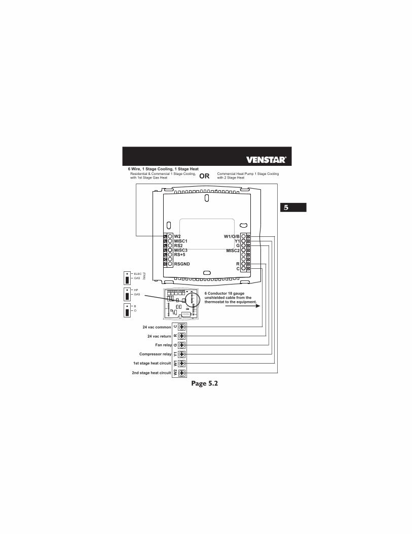
6 Conductor 18 gauge unshielded cable from the thermostat to the equipment.
24 vac return
Fan relay
Compressor relay
1st stage heat circuit W1
W2
G
RC
Y1
RS2
6 Wire, 1 Stage Cooling, 1 Stage Heat
24 vac common
2nd stage heat circuit
MISC3
HP
GAS
B
O
ELEC
GAS
(FA
N)
Residential & Commercial 1 Stage Cooling, with 1st Stage Gas Heat
Commercial Heat Pump 1 Stage Cooling with 2 Stage HeatOR
Page 5.2
5

HP
GAS
B
O
ELEC
GAS
(FA
N)
W1
Y1
G
R
C
MISC2
W2
MISC1
RS2
RSGND
MISC3
RS+5
W3
HUM
DEHUM
MISC3 MISC2 MISC1
Y2(MISC1ONLY)
INSTALL HUMIDITY MODULE WITH SENSING
ELEMENT OUTWARD
HU
M
NO
HU
M
Y1G
RC
MISC2
W1/O/BMISC1
RS+5
RSGND
W2
6 Conductor 18 gauge unshielded cable from the thermostat to the equipment.
24 vac return
Fan relay
Compressor relay
1st stage heat circuit W1
W2
G
RC
Y1
RS2
Residential & Commercial 1 Stage Cooling, with 1st Stage Electric Heat
6 Wire, 1 Stage Cooling, 1 Stage Heat
24 vac common
2nd stage heat circuit
MISC3
HP
GAS
B
O
ELEC
GAS
(FA
N)
Page 5.3
5
HP
GAS
B
O
ELEC
GAS
(FA
N)
W1
Y1
G
R
C
MISC2
W2
MISC1
RS2
RSGND
MISC3
RS+5
W3
HUM
DEHUM
MISC3 MISC2 MISC1
Y2(MISC1ONLY)
INSTALL HUMIDITY MODULE WITH SENSING
ELEMENT OUTWARD
HU
M
NO
HU
M
Y1G
RC
MISC2
W1/O/BMISC1
RS+5
RSGND
W2
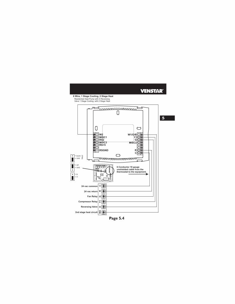
6 Conductor 18 gauge unshielded cable from the thermostat to the equipment.
24 vac return
Fan Relay
Compressor Relay
Reversing Valve OW
2
GR
CY
1
RS2
Residential Heat Pump with O Reversing Valve 1 Stage Cooling, with 2 Stage Heat
6 Wire, 1 Stage Cooling, 2 Stage Heat
24 vac common
2nd stage heat circuit
MISC3
HP
GAS
B
O
ELEC
GAS
(FA
N)
Page 5.4
5
HP
GAS
B
O
ELEC
GAS
(FA
N)
W1
Y1
G
R
C
MISC2
W2
MISC1
RS2
RSGND
MISC3
RS+5
W3
HUM
DEHUM
MISC3 MISC2 MISC1
Y2(MISC1ONLY)
INSTALL HUMIDITY MODULE WITH SENSING
ELEMENT OUTWARD
HU
M
NO
HU
M
Y1G
RC
MISC2
W1/O/BMISC1
RS+5
RSGND
W2
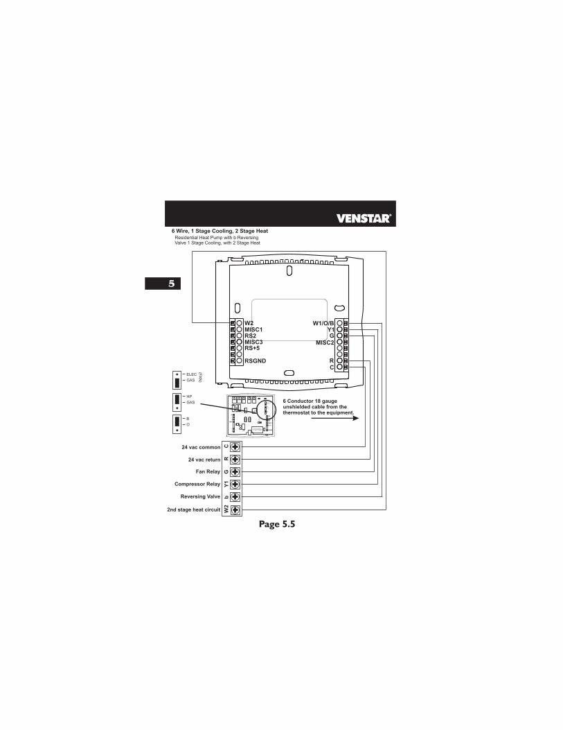
6 Conductor 18 gauge unshielded cable from the thermostat to the equipment.
24 vac return
W2
G
RC
Y1
RS2
Residential Heat Pump with b Reversing Valve 1 Stage Cooling, with 2 Stage Heat
6 Wire, 1 Stage Cooling, 2 Stage Heat
24 vac common
2nd stage heat circuit
MISC3
HP
GAS
B
O
ELEC
GAS
(FA
N)
Fan Relay
Compressor Relay
Reversing Valve b
Page 5.5
5
HP
GAS
B
O
ELEC
GAS
(FA
N)
W1
Y1
G
R
C
MISC2
W2
MISC1
RS2
RSGND
MISC3
RS+5
W3
HUM
DEHUM
MISC3 MISC2 MISC1
Y2(MISC1ONLY)
INSTALL HUMIDITY MODULE WITH SENSING
ELEMENT OUTWARD
HU
M
NO
HU
M
Y1G
RC
MISC2
W1/O/BMISC1
RS+5
RSGND
W2
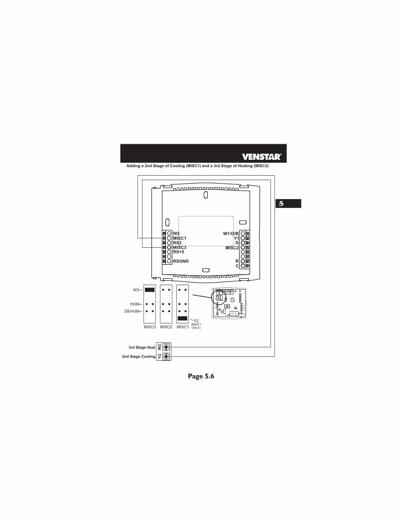
2nd Stage Cooling Y2
W3
RS2
Adding a (MISC1) and a (MISC3)2nd Stage of Cooling 3rd Stage of Heating
3rd Stage Heat
MISC3
W3
HUM
DEHUM
MISC3 MISC2 MISC1
Y2(MISC1ONLY)
Page 5.6
5
HP
GAS
B
O
ELEC
GAS
(FA
N)
W1
Y1
G
R
C
MISC2
W2
MISC1
RS2
RSGND
MISC3
RS+5
W3
PROG
HUM
DEHUM
MISC3 MISC2 MISC1
Y2(MISC1ONLY)
INSTALL HUMIDITY MODULE WITH SENSING
ELEMENT OUTWARD
1
2 4 6 8 X Z
1 5 7 9 Y3
HU
M
NO
HU
M
Y1G
RC
MISC2
W1/O/BMISC1
RS+5
RSGND
W2
RS2
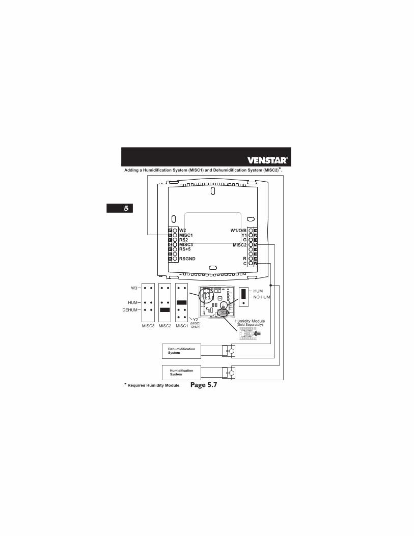
Adding a Humidification System (MISC1) and Dehumidification System (MISC2)*.
MISC3
DehumidificationSystem
W3
HUM
DEHUM
MISC3 MISC2
Y2(MISC1ONLY)
Humidification System
MISC1
HUM
NO HUM
Page 5.7
5
1
2 4 6 8 X Z
1 5 7 9 Y3
Humidity Module(Sold Separately)
* Requires Humidity Module.
Page 5.8
5
Installing the Outdoor Sensor
See the Outdoor Sensor accessory for further details.
The Outdoor Sensor measures outdoor air temperature and sends this information to the thermostat; it measures temperature with a range of -40 to 127 F.
The Outdoor Sensor should be connected to the thermostat usingsolid conductor CAT 5, CAT 5e, or CAT 6 type network commun-ication cable. This is an unshielded cable with four twisted pairs of 24 gauge solid wire; DO NOT use stranded cable. The cable length should not exceed 250 feet. If less than 75 feet of cable is required to connect the thermostat to the Remote Sensor, a three conductor thermostat cable (18-24 gauge) may be used; this cable is NOT suitable for any length greater than 75 feet.
IMPORTANT: Do no use shielded wire. Do not run sensor wiring in the same conduit as the 24VAC thermostat wiring. Electrical interference may cause the sensor to give incorrect temperature readings.
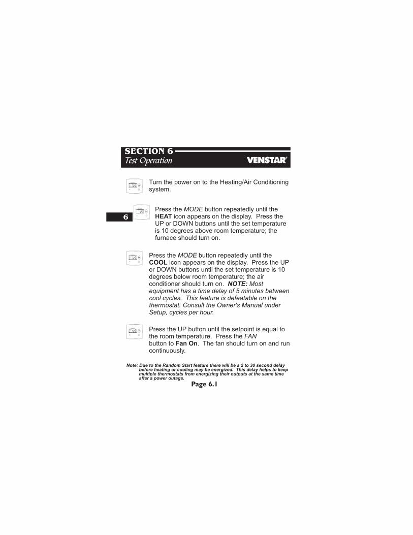
Press the MODE button repeatedly until the HEAT icon appears on the display. Press UP or DOWN buttons until the set temperature is 10 degrees above room temperature; the furnace should turn on.
the
Press the MODE button repeatedly until the COOL icon appears on the display. or DOWN buttons until the set temperature is 10 degrees below room temperature; the air conditioner should turn on. NOTE: Most equipment has a time delay of 5 minutes between cool cycles. This feature is defeatable on thethermostat. Consult the Owner's Manual under Setup, cycles per hour.
Press the UP
Turn the power on to the Heating/Air Conditioning system.
6
Page 6.1
SECTION 6Test Operation
Press the UP button until the setpoint is equal to the room temperature. Press the FAN button to Fan On. The fan should turn on and run continuously.
Note: Due to the Random Start feature there will be a 2 to 30 second delay before heating or cooling may be energized. This delay helps to keep multiple thermostats from energizing their outputs at the same time after a power outage.
AUTO
I2:00 Pm
HEAT
COOL
72
74
AUTO
I2:00 Pm
HEAT
COOL
72
74
AUTO
I2:00 Pm
HEAT
COOL
72
74
AUTO
I2:00 Pm
HEAT
COOL
72
74
Page 7.1
SECTION 7Calibrating the Thermostat Sensors
7
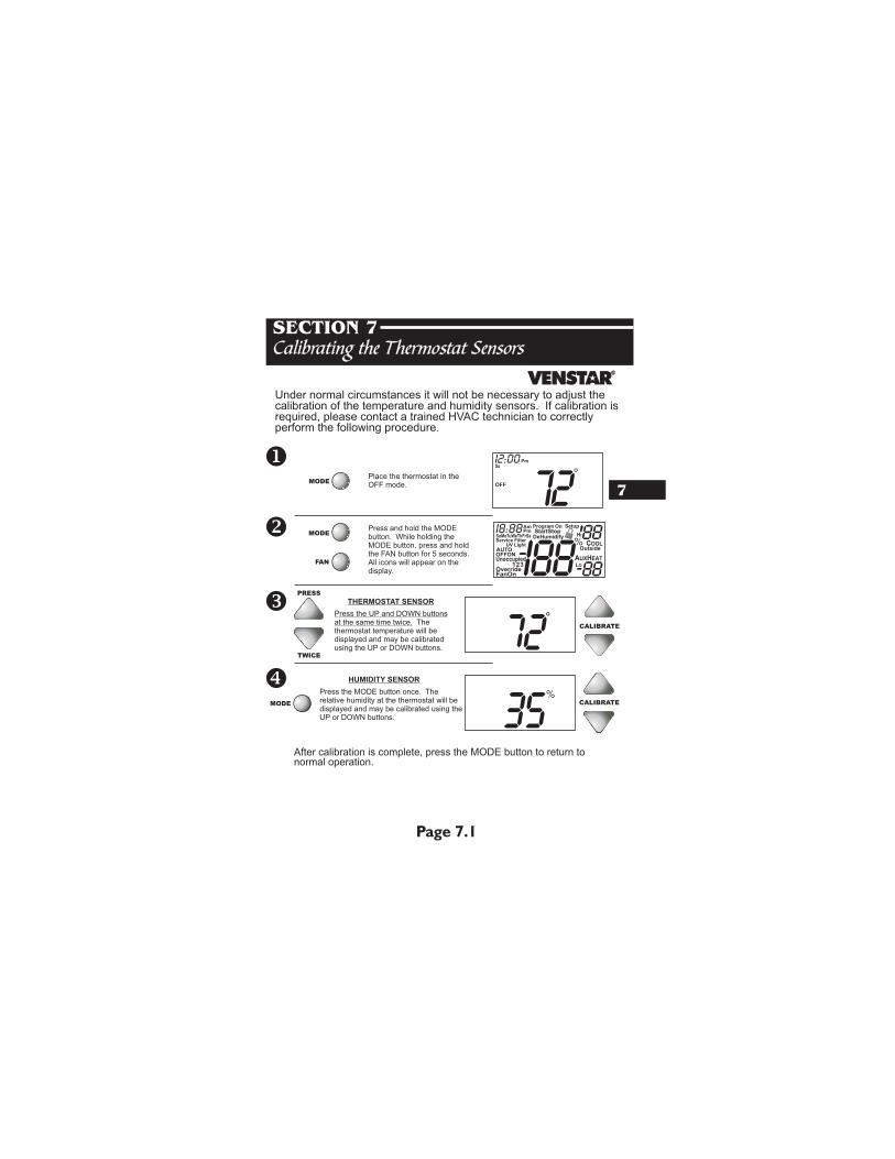
After calibration is complete, press the MODE button to return to normal operation.
OFF
I2:00
72Pm
PRESS
TWICE
FAN
MODE
MODEPress button. While holding theMODE button, press and hold the FAN button for 5 seconds.All icons will appear on thedisplay.
and hold the MODE
Under normal circumstances it will not be necessary to adjust the calibration of the temperature and humidity sensors. If calibration is required, please contact a trained HVAC technician to correctly perform the following procedure.
Place the thermostat in the OFF mode.
Press the UP and buttons at the same time twice. The thermostat temperature will be displayed and may be calibrated using the UP or DOWN buttons.
DOWN
CALIBRATE
CALIBRATE
THERMOSTAT SENSOR
Su
MODE
Press the MODE button once. The relative humidity at the thermostat will be displayed and may be calibrated using theUP or DOWN buttons.
HUMIDITY SENSOR
AUTOOFFON
Override
Unoccupied
AmI8:88SuMoTuWeThFrSa
Pm
AUXHEAT
COOL
FanOn
Service FilterUV Light
Program OnStartStop
DeHumidify
I88Setup
Outside
88LO
HI88
123
Page 8.1
SECTION 8TroubleShooting
8
SYMPTOM: The air conditioning does not attempt to turn on.CAUSE: The compressor timer lockout may prevent the air conditioner from turning on, for a period of time.REMEDY: Consult the Owner's Manual in the Setup section to defeat the cycles per hour and compressor timeguard.
SYMPTOM: The display is blank.CAUSE: Lack of proper power.REMEDY: Make sure power is turned on to the furnace and that you have 24vac between R & W. If C is used, 24vac between R & C.
SYMPTOM: The air conditioning does not attempt to turn on.CAUSE: The cooling setpoint is set too high.REMEDY: Consult the Owner's Manual in the Setup section to lower the cooling setpoint limit.
SYMPTOM: The heating does not attempt to turn on.CAUSE: The heating setpoint is set too low.REMEDY: Consult the Owner's Manual in the Setup section to raise the heating setpoint limit.
Note: Due to the Random Start feature there will be a 2 to 30 second delay before heating or cooling may be energized. This delay helps to keep multiple thermostats from energizing their outputs at the same time after a power outage.
AUTO
I2:00 Pm
HEAT
COOL
72
74
AUTO
I2:00 Pm
HEAT
COOL
72
74
AUTO
I2:00 Pm
HEAT
COOL
72
74
AUTO
I2:00 Pm
HEAT
COOL
72
74
SYMPTOM: When controlling a residential heat pump, and asking for cooling, the heat comes on.CAUSE: The thermostat reversing valve jumper is set for “b”.REMEDY: Set the reversing valve jumper for “O”. See pages 5.4 and 5.5.
SYMPTOM: When calling for cooling, both the heat and cool come on.CAUSE: The thermostat equipment jumper is configured for “HP” and the HVAC unit is a Gas/Electric.REMEDY: Set the equipment jumper for “Gas”. See pages 5.2 and 5.3.
P/N 88-604Rev. 1Page 8.2
8
TroubleShooting
Note: Due to the Random Start feature there will be a 2 to 30 second delay before heating or cooling may be energized. This delay helps to keep multiple thermostats from energizing their outputs at the same time after a power outage.
AUTO
I2:00 Pm
HEAT
COOL
72
74
AUTO
I2:00 Pm
HEAT
COOL
72
74