Embed Size (px)
Citation preview

ThermoPlus AS2-RF & ASR-RFInstallation Instructions
The Horstmann ThermoPlus AS2-RF is a wireless room thermostat that has been designed to make its operation very simple for the householder.
The built in automatic clock means it will not need setting or adjusting for BST and GMT time changes.
The ThermoPlus will provide a Warm temperature setting at times pre-set by you installer and day-to-day user adjustments are carried out using just three buttons.
The AS2-RF kit is supplied in two parts. The receiver which is hard wired to the combi or conventional system boiler and the AS2-RF thermostat which can be used in any normal domestic environment within a typical 30 metre range without the need for any costly or disruptive wiring.
1
ThermoPlus AS2-RF - Product Overview
The AS2-RF thermostat kit is made up of two parts:1 x receiver Receiver1 x AS2-RF Transmitter
Both parts have been designed to be easily installed and offer
maximum flexibility. No hard wiring is required between the
transmitter and the receiver. The receiver unit is hard wired to
the boiler and should be sited close to the existing wiring. The
AS2-RF can then be positioned up to 30 metres away - Range
will vary depending upon the composition, density and number
of walls between the AS2-RF transmitter and the receiver.
2

AS2 RF Transmitter
POSITIONING OF VALVE
3
1 - Plus '+' Button 6 - Standby Time/Set Button2 - LED Indicator lights 7 - Increase/Decrease Buttons3 - Installer Display 8 - Prog/Exit Button4 - 'Warm/Cool' Button 9 - Front flap shown open5 - Minus '-' Button

Part 1 – Day to Day operation
The ThermoPlus AS2-RF has been designed to be a simple to use thermostat, requiring minimal user intervention with a pre-programmed heating profile. Simple temperature adjustments can be easily carried out by using the '+' and '-' buttons. The indicator lights react to any temporary user adjustments, with the LED indicators working in the following way;
'Warm' is shown by two red lights and 'Cool' is shown by a single blue light (see Power Down Mode below). The centre button marked 'Warm/Cool' allows you to toggle between the warm and cool settings.
When one or more red lights are on, you can increase the temperature by pressing the '+'button. For example, press once to go up by 1°C or press twice to go up by 2°C.
When the two or three red lights are on, the temperature can also be lowered by using the '-' button. For example, press once to go down to the warm setting temperature and press again to go down to 1°C below warm setting temperature. (Maximum adjustment to warm temperature +/- 2°C). The blue light indicates the unit is working to the lower set temperature. Please note that the '+' or '-' buttons will have no effect on the lower temperature setting.
Under the flap is a blue button (6). During the summer, or when you want your central heating off for long periods, for example if you go on holiday, press the blue button and close the flap. When you want to go back to normal operation, open the flap and press the blue button again, remembering to close the flap once finished.
Both the Warm and Cool temperature settings can be permanently adjusted, this operation is detailed on page 6.
4
Power Down Mode
During normal operation the AS2-RF will go into Power Down Mode, this is to maximise the life of the 3 x AA batteries fitted. Normal operation will continue during this mode, and the heating will be unaffected. The result of the Power Down Mode will mean that the LED indicators will not be displayed and LCD will not be illuminated, although the 'Warm' or 'Cool' temperature will be displayed.
To 'wake up' the AS2-RF press the 'Warm/Cool' button for 5 seconds, this will then illuminate both the LED and LCD displays for a period. Any adjustment can then be made, the Power Down Mode will commence again approximately 8 seconds after the last button press.
5

Warm and Cool Temperature Adjustment
The Warm and Cool target temperature settings on the ThermoPlus AS2-RF are fully adjustable. To change a target temperature it is first necessary to press the centre button to bring up the 'Warm' or 'Cool' setting (indicated by the red or blue LED indicators).
By using the up/down keys under the flap the Warm/Cool temperature can be increased or decreased to the desired temperature setting.
PLEASE NOTE – it is not possible to set the warm setting to below that of the cool setting or vice versa.
Once a new temperature has been set in either the Warm or Cool setting the AS2- RF will continue to use this setting until the next manual adjustment.
6
Press here to selectWarm or Cool

7
To increasePress
To decreasePress
Warm and Cool Temperature Adjustment

Audible Feedback
All buttons on the AS2-RF give an audible confirmation when pressed. A short bleep means 'Yes', a longer buzz means 'No' – the setting/adjustment cannot be done.
Frost Protection
The blue button situated under the flap will initiate the frost protection mode, when pressed the word 'STANDBY' will appear on the display, the thermostat has been pre- programmed with a frost protection temperature level of 7°C, this can be adjusted by using the up and down arrow buttons. Minimum setting 5°C. It is not possible to set a frost protection temperature above the cool setting.
Part 2 – Programming Mode
The ThermoPlus AS2-RF has been designed for minimal user intervention, however should any changes to the existing programme be required please press button 6 and 8 simultaneously to enter the programming mode, this will allow you to;
Check the current time/date/yearCheck the current profileSet a new pre-set profile orSet a user defined profile
Please note: Upon completion of any of the adjustments above, please ensure that you exit the programming mode by pressing buttons 6 and 8 simultaneously.
8
6
8
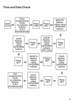
Time and Date Check
9
OpenCover
Enter programming
mode by pressing
buttons6 & 8
simultaneously
PressTIME
PressSET
MINUTE flashes.
Adjust using UP/DOWN
buttons
PressSET
HOURflashes,Adjust using
UP/DOWN buttons
24hr clock
PressSET
DATEflashes,Adjust using
UP/DOWN buttons
PressSET
MONTHflashes,Adjust using
UP/DOWN buttons
PressSET
YEARflashes,Adjust using
UP/DOWN buttons
PressSET
PressSET
DATEflashes,Adjust using
UP/DOWN buttons
Exit programming
mode by pressing
buttons6 & 8
simultaneously

10
Setting Heating Profiles
Open Cover
Enter programming mode by pressing buttons 6 & 8 simultaneously
Press PROG
Press SET
Select the required profile by using the UP/DOWN buttons
Press SET
Press EXIT
Exit PROGRAMMING mode by pressing buttons 6 & 8 simultaneously
To review presetprofiles 1 to 5 press
UP button (7) repeatedly
11
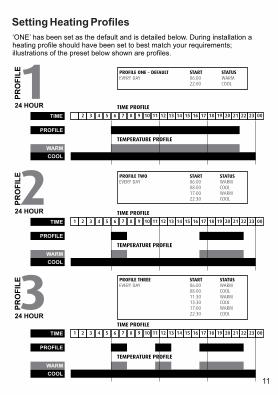
‘ONE’ has been set as the default and is detailed below. During installation a heating profile should have been set to best match your requirements; illustrations of the preset below shown are profiles.
PROFILE ONE – DEFAULT START STATUSEVERY DAY 06:00 WARM
22:00 COOL
PROFILE TWO START STATUSEVERY DAY 06:00 WARM
08:00 COOL
17:00 WARM
22:30 COOL
PROFILE THREE START STATUSEVERY DAY 06:00 WARM
08:00 COOL11:30 WARM13:30 COOL17:00 WARM 22:30 COOL
1PROFILE
24 HOUR
2PROFILE
24 HOUR
3PROFILE
24 HOUR
1
1
TIME
TIME
TIME
PROFILE
PROFILE
PROFILE
WARM
WARM
WARM
COOL
COOL
COOL
2
2
2
3
3
3
4
4
4
5
5
5
6
6
6
7
7
7
8
8
8
9
9
9
10
10
10
11
11
11
12
12
12
13
13
13
14
14
14
15
15
15
16
16
16
17
17
17
18
18
18
19
19
19
20
20
20
21
21
21
22
22
22
23
23
23
00
00
00
TIME PROFILE
TIME PROFILE
TIME PROFILE
TEMPERATURE PROFILE
TEMPERATURE PROFILE
TEMPERATURE PROFILE
Setting Heating Profiles

Setting Heating Profiles
START STATUS START STATUSMON - FRI 06:00 WARM SAT/SUN 07:00 WARM
08:00 COOL 22:00 COOL11:30 WARM13:30 COOL17:00 WARM 22:30 COOL
PROFILE FIVE START STATUS START STATUSMON - FRI 06:00 WARM SAT/SUN 07:00 WARM
08:00 COOL 22:00 COOL
17:00 WARM
22:30 COOL
4PROFILE
5/2 DAY
5PROFILE
1
5/2 DAY
1
TIME
TIME
MON - FRI
MON - FRI
SAT/SUN
SAT/SUN
WARM
WARM
WARM
WARM
COOL
COOL
COOL
COOL
2
2
3
3
4
4
5
5
6
6
7
7
8
8
9
9
10
10
11
11
12
12
13
13
14
14
15
15
16
16
17
17
18
18
19
19
20
20
21
21
22
22
23
23
00
00
TIME PROFILE
TIME PROFILE
TEMPERATURE PROFILE
TEMPERATURE PROFILE
MON - FRI
MON - FRI
SAT/SUN
SAT/SUN
Profiles one to five have fixed periods, no alteration to the Warm/Cool times can be made,if it is necessary to make any alterations then profile six must be used. Profile six will allow you to set up a profile to your exact requirements. Please refer to the flowchart on page 14.
12

6PROFILE User Definable - 7 Day Programming
Profile 6 will allow you to set up a profile to your exact requirements. By using the flow chart below you can adjust the Warm/Cool timing periods as required. If
only one or two Warm/Cool periods are required on any day set the times accordingly and set the remaining Warm and Cool start times to be exactly the same as each other.
This will cancel the 2nd or 3rd Warm/Cool periods altogether for the day concerned. Unused periods will be shown by a series of dashes on the settings screen. Press SET and the next day and SET appears in the display. Press SET to adjust the next days settings or EXIT to return to the main menu. To do this press SET until the next day and SET appears in the display. Unused periods will be shown by a series of dashes on the setting screen.
If one or two periods have been set and you wish to return to three periods in 24 hours then pressing the up arrow when the dashes appear after the last Cool setting will bring back the hidden Warm/Cool settings.
13
C
D
B
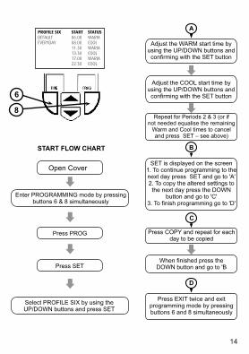
PROFILE SIX START STATUS DEFAULT 06:00 WARMEVERYDAY 08:00 COOL
11:30 WARM13:30 COOL17:00 WARM22:30 COOL
START FLOW CHART
A
8
6
Open Cover
Enter PROGRAMMING mode by pressingbuttons 6 & 8 simultaneously
Press PROG
Press SET
Select PROFILE SIX by using theUP/DOWN buttons and press SET
Adjust the WARM start time by using the UP/DOWN buttons and confirming with the SET button
Adjust the COOL start time by using the UP/DOWN buttons and confirming with the SET button
Repeat for Periods 2 & 3 (or if not needed equalise the remaining
Warm and Cool times to cancel and press SET – see above)
SET is displayed on the screen1. To continue programming to the next day press SET and go to 'A'2. To copy the altered settings to the next day press the DOWN
button and go to 'C'3. To finish programming go to 'D'
Press COPY and repeat for each day to be copied
When finished press the DOWN button and go to 'B
Press EXIT twice and exit programming mode by pressing buttons 6 and 8 simultaneously
14
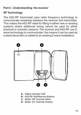
Part 3 – Understanding the receiver
RF Technology
The AS2-RF thermostat uses radio frequency technology to communicate wirelessly between the receiver and transmitter. This makes the AS2-RF ideal for fitting in either new or existing systems where additional wiring cannot be used for either practical or cosmetic reasons. The receiver and AS2-RF use Z-wave technology to communicate, this means it can be used as a stand alone item or added to an existing Z-wave installation.
A – Status Indicator LEDB – AS2-RF Add/Remove ButtonsC – Boiler ‘Off’ Override (Red)D – Boiler ‘On’ Override (Green)
A B
C D
15
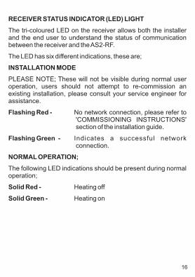
RECEIVER STATUS INDICATOR (LED) LIGHT
The tri-coloured LED on the receiver allows both the installer and the end user to understand the status of communication between the receiver and the AS2-RF.
The LED has six different indications, these are;
INSTALLATION MODE
PLEASE NOTE; These will not be visible during normal user operation, users should not attempt to re-commission an existing installation, please consult your service engineer for assistance.
Flashing Red - No network connection, please refer to 'COMMISSIONING INSTRUCTIONS' section of the installation guide.
Flashing Green - Indicates a successful network connection.
NORMAL OPERATION;
The following LED indications should be present during normal operation;
Solid Red - Heating off
Solid Green - Heating on
16

RECEIVER STATUS INDICATOR (LED) LIGHT
FAIL SAFE MODE
If, during normal operation, the RF signal is lost for more than 60 minutes then the receiver will switch to Fail Safe Mode (off). During Fail Safe Mode the receiver relay/heating will be switched off and can be controlled by using the emergency red (off) and green (on) buttons located below the flap on the receiver if required, further details are given in the following sections. When the emergency buttons are used the LED will operate in the following way;
Solid Amber - Heating off - indicating no message from AS2-RF for 60 minutes
Flashing Amber - Heating on - Green override button activated
PLEASE NOTE; The red and green override buttons on the receiver will only operate in fail safe mode. In normal operation pressing these buttons will have no effect.
Communication Fail Safe Modes
RECEIVER FAIL SAFE MODE
Should your receiver enter the Fail Safe Mode this will be conveyed by the LED indicator going solid amber. This will only happen if the receiver has not received a signal from the AS2-RF for more than 60 minutes. Some basic instructions are detailed in the previous section and on the inside of the receiver flap for the emergency use of the relay/heating during this mode.
17
To resume normal operation please use the following procedures;
Press the 'Warm/Cool' button on the front of the AS2-RF for 5 seconds, or until the display illuminates, then press again to send a signal to the receiver, if successful this will be indicated by the LED on the receiver changing from amber to either red or green.
Or
Check and replace, if necessary, the 3 x AA batteries in the AS2-RF transmitter, then follow the process above.
If the processes above fail to regain normal operation then please consult your heating or service engineer for further assistance.
OPERATING MODES
During normal operation the receiver will indicate the boiler status through the colour of its LED, please refer to the RECEIVER STATUS INDICATOR LED on page 19.
The AS2-RF also uses a combination of LED and LCD displays to assist the user to gain maximum benefit from the thermostat. During normal operating period, where no user intervention has occurred, the AS2-RF will power down to maximize battery life. To 'wake' the AS2-RF press the Warm/Cool for 5 seconds, the displays, both LED and LCD will now illuminate and will stay lit for a period of 8 seconds after the last button press.
For more information on Z Wave technology please visit www.zen-sys.com
18
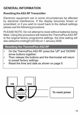
GENERAL INFORMATION
Resetting the AS2-RF Transmitter
Electronic equipment can in some circumstances be affected by electrical interference. If the display becomes frozen or scrambled; or if you wish to revert back to the default settings please use the following procedure.
PLEASE NOTE: Do not attempt to reset without batteries being fitted. Using this procedure will restore the ThermoPlus AS2-RF to the original factory programme settings, the time setting will also default to midnight (00:00) on 1 January 2006.
On the ThermoPlus AS2-RF press the 'UP' and 'DOWN'
arrow buttons together: Then release the buttons and the thermostat will return
to preset factory settings. Reset the time and date as shown on page 9.
Resetting the ThermoPlus AS2-RF
To reset press
19

Battery Replacement
The ThermoPlus AS2-RF uses 3 x AA (LR6) batteries. The batteries supplied with the unit should last for approximately two years. When the batteries are nearing the end of their life a 'LOW BAT' message will flash on the display.
To change the batteries it is necessary to remove the AS2-RF from the wall, to achieve this first press the RELEASE BUTTONS located under the unit and pull the AS2-RF away from the mounting plate by gently pulling up.
Before removing the old batteries please wait for at least 15 seconds after the last button was pressed. Remove old batteries and ensure the L.C.D display has gone blank before fitting the new batteries.
Replace with three new AA size alkaline batteries, ensure they are fitted correctly as shown by the marking positioned between the battery terminals. Once batteries have been fitted, replace the AS2-RF to the mounting plate, ensuring that the two guide lugs are fitted into the corresponding slots in the top of the mounting plate. Now push the AS2-RF until the release button clicks into place.
WARNING: You must ensure that the AS2-RF is always running on 3 x AA batteries and when the battery low message is displayed it is important that they are changed as soon as possible. This is to preserve the secondary internal reserve battery which is non- replaceable.
For best results use alkaline batteries rather than zinc carbon batteries.
20
No Signal Indicator
Should your AS2-RF enter the Fail Safe Mode this will be conveyed by the LCD display showing 'No Sig' every 3 seconds. This indicates that the AS2-RF has not received a signal to confirm the last 'Warm / Cool' change from the receiver.
To resume normal operation please use the following procedures;
1. Press the 'Warm / Cool' button on the front of the AS2-RF for 5 seconds, or until the display illuminates, then press again to send a signal to the receiver, if successful this will make the 'No sig' flag disappear .
or
2. Check the receiver, if the LED is not illuminated this indicates a power interruption or disconnection. In this case, the mains supply should be checked and if it cannot be restored the assistance of an electrician or service engineer should be sought.
Service and Repair
The ThermoPlus AS2-RF is NOT user serviceable. Please do not dismantle the unit.
In the event of a fault developing please refer to the RESETTING THE AS2-RF TRANSMITTER section on page 14. If this fails to resolve the problem please contact a local heating engineer or a qualified electrician.
21

What is a programmable room thermostat?…an explanation for householders.
A programmable room thermostat is both a programmer and a room thermostat. A programmer allows you to set 'ON and OFF' time periods to suit your own lifestyle. A room thermostat works by sensing the air temperature, switching on the heating when the air temperature falls below the thermostat setting and switching it off once the set temperature has been reached.
So, a programmable room thermostat lets you choose what times you want the heating to be on, and what temperature it should reach while it is on. It will allow you to select different temperatures in your home at different times of the day (and days of the week) to meet your particular needs.
Turning a programmable room thermostat to a higher setting will not make the room heat up any faster. How quickly the room heats up depends on the design of the heating system, for example, the size of the boiler and radiators.
Neither does the setting affect how quickly the room cools down. Turning a programmable room thermostat to a lower setting will result in the room being controlled at a lower temperature, and saves energy.
The way to set and use your programmable room thermostat is to find the lowest temperature settings that you are comfortable with at the different times you have chosen, and then leave it alone to do its job. The best way to do this is to set low temperatures first, say 18ºC and then turn them up by one degree each day until you are comfortable with the temperatures. You won't have to adjust the thermostat further. Any adjustments above these settings will waste energy and cost you more money.
22

If your heating system is a boiler with radiators, there will usually be only one programmable room thermostat to control the whole house. But you can have different temperatures in individual rooms by installing thermostatic radiator valves (TRVs) on individual radiators. If you don't have TRVs, you should choose a temperature that is reasonable for the whole house. If you do have TRVs, you can chose a slightly higher setting to make sure that even the coldest room is comfortable, then prevent any overheating in other rooms by adjusting the TRVs.
The time on the programmer must be correct. Some types have to be adjusted in spring and autumn at the changes between Greenwich Mean Time and British Summer Time.
You may be able to temporarily adjust the heating programme, for example, 'Override', 'Advance' or 'Boost'. These are explained in the manufacturer's instructions.
Programmable room thermostats need a free flow of air to sense the temperature, so they must not be covered by curtains or blocked by furniture. Nearby electric fires, televisions, wall or table lamps may prevent the thermostat from working properly.
23

Part Number 83021 Issue 2
South Bristol Business Park, Roman Farm Road, Bristol BS4 1UP t: +44 117 978 8700e: [email protected]