Embed Size (px)
Citation preview

Thermometry Issues in Destruction Kinetics Measurement
June 9, 2009
Dean [email protected]
NIST Thermometry Group
Overview of thermometer types, terminology, & general issues
Detailed discussion of different thermometer types
Verification & good practice

Effects of Temperature on MicrobesSmall temperature changes:
Arrhenius Equation: reaction rate constant proportional to (Ea = activation energy, R = gas constant, T = absolute temperature)
Modification of protein enzymatic kinetics
Even small changes in temperature, at relatively low temperature, can lead to significant changes in rate of microbial inactivation
Large temperature changes:Activation of protective pathways (e.g., heat-shock proteins)
Physical alterations to proteins, DNA
Accurate thermometry aids in determination of damage thresholds
Accurate measurements ensure validity and interchangeability of kinetics data, for both thermal and thermally assisted inactivation
RTEae−

Tolerances vs. Calibration Uncertainties
Tolerance band: manufacturer’s guarantee that the instrument response will conform to a standard response function to within an error equal to the tolerance.
Calibrated thermometer: may or may not have a response close to the nominal response function for that thermometer type.
Response of individual unit is reported. Expanded uncertainties (95 % confidence limit, or ‘coverage factor k = 2’) typically reported for calibration measurement—not including drift & user readout
Individually calibrated thermometers are not interchangeable, unless the readouts or software are adjusted.

Typical Measurement Uncertainty Budget
Note that only the first item is included in the initial calibration or manufacturing tolerance
Component Method of evaluation
Calibration uncertainty or tolerance Manufacturer, calibration report, or tolerance
Sensor drift Literature, manufacturer, recalibration, or in situ check
Readout uncertainty Manufacturer or independent evaluation
Temperature stability Logging of temperature
Temperature non-uniformity Move probe or use multiple probes

Thermometer Types
Standard Platinum Resistance Thermometers (SPRTs) $6000(very accurate, but susceptible to shock)
−259 °C to 962 °C
Industrial Platinum Resistance Thermometers (IPRTs) $200 to $2000–196 °C to 850 °C
Thermistors $200 to $2000–50 °C to 100 °C
Thermocouples $100 to $1000–196 ° C to 2100 °C
Liquid-in-Glass Thermometers $20 to $400–150 °C to 400 °C
Digital Thermometers (PRT, thermistor, or thermocouple in disguise)–196 °C to 850 °C

Approximate Measurement Uncertainties of Complete Systems
0.001
0.010
0.100
1.000
10.000
-100 0 100 200Temperature, °C
Tole
ranc
e or
95%
con
fiden
ce
unce
rtain
ty, °
CPRT, ASTM Class A PRT, calibratedThermistor, interchangeable Thermistor, calibratedBase metal thermocouple Organic liquid-filled
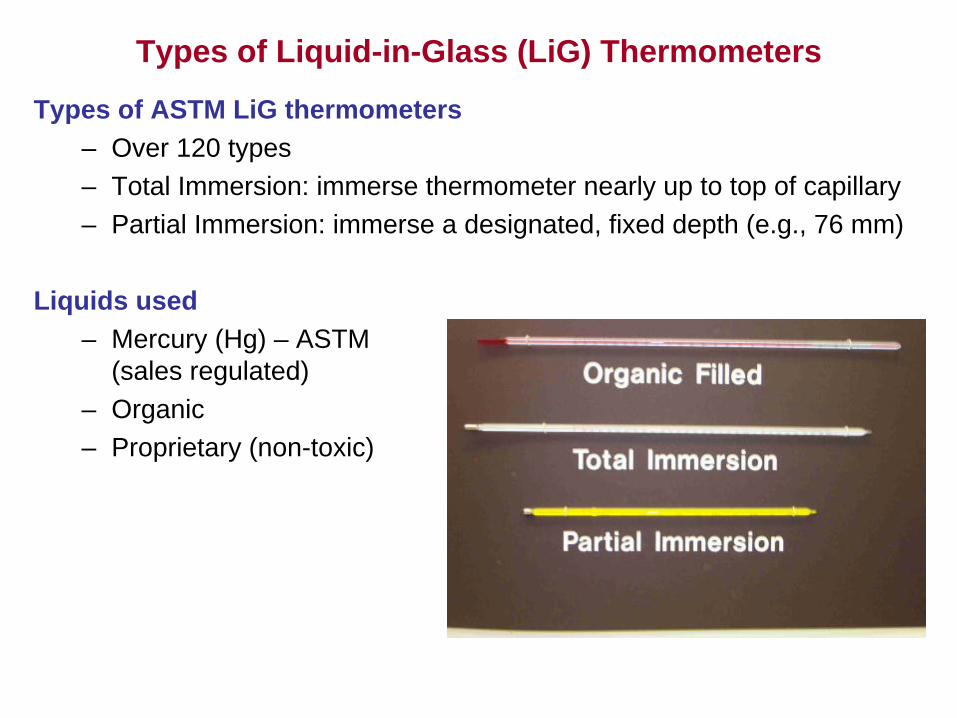
Types of Liquid-in-Glass (LiG) Thermometers
Types of ASTM LiG thermometers– Over 120 types– Total Immersion: immerse thermometer nearly up to top of capillary– Partial Immersion: immerse a designated, fixed depth (e.g., 76 mm)
Liquids used– Mercury (Hg) – ASTM
(sales regulated)– Organic– Proprietary (non-toxic)

Non-Mercury Liquid-in-Glass Thermometers
• Organic liquids generally have inferior performance to mercury, but are a reasonable alternative if uncertainty requirements are modest
• Beware of drainage of organic liquid down capillary wall on cooling
• “Next-generation” organic liquids under development (Existing ASTM standard E2251); good accuracy, but check for separation of liquid column
• Greater sensitivity to stem temperature: a fundamental limitation for partial immersion thermometers—total immersion preferred
• Best results for use at steady operating temperatures, within range −100 °C to +100 °C; attainable expanded uncertainties of approximately 0.5 °C to 1 °C for properly used total immersion.

Thermocouples
Standardized combinations of Material A vs. Material B (e.g, Type K).
When combined with typical readout uncertainty, total uncertainty is fairly large, unless care is taken with calibration.
Good for low-accuracy measurements over a broad temperature range
Type K is a good choice for sterilization applications; typical drift of 0.3 °C over one year at 200 °C, for fixed installation
T0
T1
Material A
Material B
Voltmeter + Junction
Compensation

Soft-Insulated Thermocouples
• Fluorocarbon insulations suitable to 200 °C (392 °F)• Note that method for forming junction does not matter!
Inner polymer insulationOuter polymer insulation
Weld or solder junction by any method
Mineral-Insulated, Metal-Sheathed (MIMS) Thermocouples
• MIMS thermocouples are available in small diameters (0.25 mm)• Sheath protects thermoelements from contamination & simplifies sterilization
“ungrounded” junction shown

Effects of Pressure on Thermocouples
Bare-wire thermocouples readily withstand high-pressure environmentsPressure distorts atomic lattice of thermoelements, resulting in small shifts in thermoelectric response.Thermocouple measurements may be useful in understanding/validating models of adiabatic heating.
R. Hanneman, Symposium on the Accurate Characterization of the High-Pressure Environment, Oct. 14-18, 1968, Gaithersburg, MD
Errors are small for typical pressures ~ 400 MPa
Error for type K = (−2.3x10⁻⁶)(Δt)(p/MPa)
Error for type S = (−1.9x10⁻⁵)(Δt)(p/MPa) where Δt = temperature span of thermocouple, p = pressure in MPa
e.g., Error for type K spanning 100 °C at 400 MPa is only −0.09 °C

Platinum Resistance Thermometers (PRTs)
Resistance element • Wire wound (most accurate, or
for wide temperature range)• Thick or thin film (rugged)
Resistance increases as a function of temperatureNominal temperature range of use:
• –200 °C to 850 °CNominal resistance at 0 °C
• 100 Ω for wire wound• often higher for film
PRTs are most common “Resistance Temperature Detector” (RTD)
Sensor or element(wire-wound shown)
Steel sheath containing sensor

ASTM E1137 “Off the Shelf” Tolerance
0.0
0.5
1.0
1.5
2.0
2.5
−250 0 250 500
Temperature, °C
Tol
eran
ce, °
C
Class AClass B
Calibrate individual units for lower uncertainty

Which Industrial PRT (IPRT) Should I Use?
Probes vs. Bare Element: probes recommended unless element is permanently mounted. Note that moisture seal at top of probe is NOT resistant to autoclaves/steam sterilization.
Film IPRTs: good time response, small size, shock resistant; not as good as wire-wound over large (>200 °C) temperature spans. Drift after 365 cycles to 160 °C ≈
0.2 °C.Wire-wound IPRTs with constrained coils: low accuracy, but shock
resistant. Drift after 365 cycles to 160 °C ≈
0.1 °C.Wire-wound IPRTs with slightly constrained coils: best accuracy
(approaching ±0.01 °C over 400 °C span), sensitive to shock. Drift better than constrained coils, but highly variable among units.
Resistor configuration– 2-wire for non-demanding applications (±5 °C)– 3-wire for ±1 °C measurements, or ±5 °C over long cables– 4-wire for all high-accuracy measurements
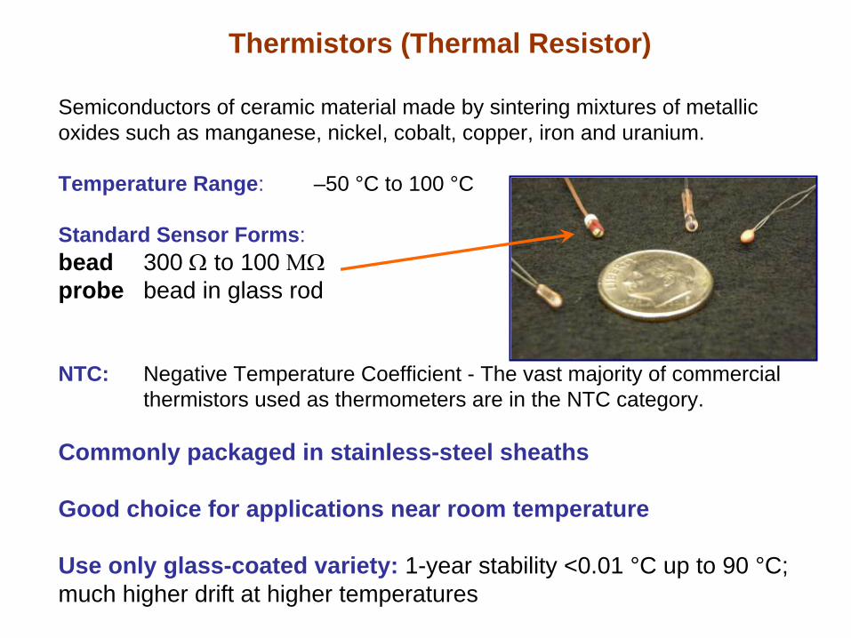
Thermistors (Thermal Resistor)
Semiconductors of ceramic material made by sintering mixtures of metallic oxides such as manganese, nickel, cobalt, copper, iron and uranium.
Temperature Range: –50 °C to 100 °C
Standard Sensor Forms:bead 300 Ω
to 100 ΜΩprobe bead in glass rod
NTC: Negative Temperature Coefficient - The vast majority of commercial thermistors used as thermometers are in the NTC category.
Commonly packaged in stainless-steel sheaths
Good choice for applications near room temperature
Use only glass-coated variety: 1-year stability <0.01 °C up to 90 °C; much higher drift at higher temperatures

What is a Digital Thermometer?Readout
Probe
Sensor inside
ASTM specifications for thermocouples, PRTs, thermistors pertain to sensor or probe only, not complete thermometer
An electronic measurement box that converts either resistance or emf of a thermometer to temperature

Digital Thermometers• Device displays temperature directly by using the calibration
coefficients of the thermometer
• Uncertainty: 0.001 °C to 1 °C; Resolution: 0.0001 °C to 1 °C
• Careful use requires careful reading—look at manufacturer’s specifications & know the probe type and limitations
• “Digital Thermometer” only means that you can watch the numbers on a display—no guarantee of better uncertainty
• Calibration can be as a system or as readout + separate probeSystem calibration is cheaper and simplerProbe and readout calibration allows easier repair if one element fails, allows identification of source of drift

Traceability of Temperature Measurements
A measurement will have traceability to NIST standards if the following conditions are met:
• An unbroken chain of measurements back to NIST standards must be maintained.
• Each step of the chain must have known and documented uncertainties.
• There must be a system to ensure that the thermometers and other equipment used remain accurate between calibrations.
Common misunderstandings:• Traceability only applies to measurements, not devices• Traceability does not imply a particular level of uncertainty• There is no limit to how many transfers may take place
between the highest-level standards and the final thermometer, as long as the uncertainty is properly calculated.

Ensuring Good Measurements1. Avoid shock to the sensor and readout. With metal-sheathed
thermometers, damage to the sensor will not be visually apparent.
2. For thermocouples, avoid kinks in the thermocouple wires, especially in regions where the temperature is changing from one point to another. For thermocouples used above 150 °C (302 °F), best uncertainties are obtained by using a separate thermocouple for each apparatus, at a fixed depth into the apparatus.
3. For resistance thermometers, calibrate and use with same lead configuration & excitation current
4. Do not switch probes unless probes are interchangeable or coefficients are updated.
5. Be absolutely certain that the readout is set to the proper thermometer type (e.g., do not read a type K thermocouple with a readout set for type J).
6. Do not exceed the recommended temperature limits.
7. Check the performance of the instrument regularly, following manufacturer’s recommendations or past device history.

Rules of Thumb for Installation Effects
• Probe location: understand the temperature differences between the probe location and the microbes of interest as a function of time (e.g., thermal modeling, study of wall vs. product temperature)
• Avoid large air gaps around probe: still air is a very poor conductor (500x worse than stainless steel)—can lead to large errors for measurement of temperature transients. Keep gaps small, or use grease.
• Design measurement geometry so at least 15 cm (6”) of probe is at temperature of interest. (Use fine diameter probes if this is not possible.)
• For fluids, physical state & conditions of flow are critical:Still gas (e.g., gas convection suppressed in insulation)Flowing gas (e.g., convection oven)Condensing vapor (e.g., steam in an autoclave)

Thermometer Verification Methods
1. Periodically have the thermometer recalibrated. If recalibration indicates that thermometer drift exceeds an allowable tolerance: • Improve handling of the thermometer • Choose thermometer with better stability, or • Shorten interval between calibrations.
2. Check the readings of the thermometer at the ice (0 °C, 32 °F) and/or steam point (near 100 °C, 212 °F) . The NIST Thermometry Group can provide simple procedures for preparing an ice or steam point.
3. Compare the reading of a thermometer to another, recently calibrated thermometer.
room-temperature comparison

Electromagnetic InterferenceNot a major issue for laboratory-scale experiments with well-
designed electronics
Design:• Noise rejection can be hard to glean from manufacturer’s readout
specifications; specifications for digital multimeters are better.• Avoid long cable runs• Use twisted pair for shielding against 60 Hz noise• If radio-frequency interference causes problems, add an outer
grounded shield• Use probes with sensor isolated (“ungrounded”) from probe wall
Diagnosis:• While continuously monitoring temperature, shut off sources of
electrical noise. If EMI is a problem, temperature will show a step change (actual temperature change will show a change in slope).

Learning More
Good general guides:Traceable Temperatures by J. Nicholas and D. R. White (Wiley, 2001) Handbook of Temperature Measurement (Vols 1-3), ed. Robin E. Bentley (Springer, 1998).
Additional reference for thermocouples:ASTM Manual on the Use of Thermocouples in Temperature Measurement, MNL-12 (ASTM, West Conshohocken, PA, 1993).
Modern uncertainty analysis: http://physics.nist.gov/cuu/Uncertainty/index.html
Methods to set calibration intervals, see:“Guidelines for the determination of calibration intervals of measuring instruments,” ILAC-G24, (International Laboratory Accreditation Cooperation, 2007).