Embed Size (px)
Citation preview

Thermolar® Tank TemperatureMaintenance System
Installation & Operation Manual for Systems Employing THS-106 or THS-206 Electronic Controller.
Precise, efficient temperature maintenance for all types of metal and plastic tanks.
INTRODUCTION
The Calorique Thermolar® Tank Temperature Maintenance System isa low heat-density warming system designed to safely and efficientlymaintain the contents temperature of any tank. Ideal for processcontrol, adhesive storage (etc.) the THERMOLAR system provides uni-form heat that won’t scorch tank contents.
When installed and operated in accordance with these instructions,the Thermolar system complies with National Electrical Code article427. Failure to install and operate this system in accordance withthe manufacturer’s instructions may result in an unsafe conditionand constitutes a violation of the system warranty and voids thatwarranty. Note that the system must be installed on a branch circuitthat is protected by a fault detector that is suitable for equipmentprotection.
PARTS & SPECIFICATIONS
PARTS — SUPPLIED BY CALORIQUE
Cross check all parts with the System Components List to ensure thatall parts are included and in good condition before beginning instal-lation. Quantities and/or lengths are included in the SystemComponents List.
The following specifications are generic to the Thermolar system.Complete specifications for the particular system being installed areincluded on the System Components List.
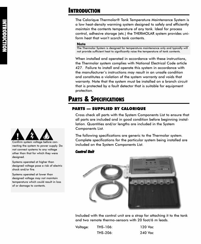
CCoonnttrrooll UUnniitt
Included with the control unit are a strap for attaching it to the tankand two remote thermo-sensors with 20 foot/6 m leads.
Voltage: THS-106: 120 Vac
THS-206: 240 Vac
INTR
OD
UCTIO
N
Confirm system voltage before con-
necting the system to power supply. Do
not connect systems to any voltage
other than that for which they were
designed.
Systems operated at higher than
designed voltage pose a risk of electric
shock and/or fire.
Systems operated at lower than
designed voltage may not maintain
temperature which could result in loss
of or damage to contents.
NoteThe Thermolar System is designed for temperature maintenance only and typically willnot provide sufficient heat to significantly raise the temperature of tank contents.
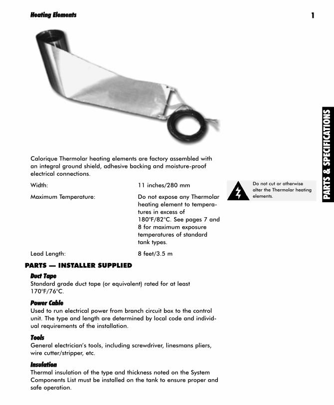
HHeeaattiinngg EElleemmeennttss
Calorique Thermolar heating elements are factory assembled withan integral ground shield, adhesive backing and moisture-proofelectrical connections.
Width: 11 inches/280 mm
Maximum Temperature: Do not expose any Thermolarheating element to tempera-tures in excess of180°F/82°C. See pages 7 and8 for maximum exposuretemperatures of standardtank types.
Lead Length: 8 feet/3.5 m
PARTS — INSTALLER SUPPLIED
DDuucctt TTaappeeStandard grade duct tape (or equivalent) rated for at least170°F/76°C.
PPoowweerr CCaabblleeUsed to run electrical power from branch circuit box to the controlunit. The type and length are determined by local code and individ-ual requirements of the installation.
TToooollssGeneral electrician’s tools, including screwdriver, linesmans pliers,wire cutter/stripper, etc.
IInnssuullaattiioonnThermal insulation of the type and thickness noted on the SystemComponents List must be installed on the tank to ensure proper andsafe operation.
Do not cut or otherwise
alter the Thermolar heating
elements.
1
PA
RTS
& S
PEC
IFIC
ATI
ON
S
INSTA
LLATIO
N
CCiirrccuuiitt OOvveerrccuurrrreenntt PPrrootteeccttiioonnFuse or circuit breaker rated for at least 120% of the systemamperage rating.
FFaauulltt PPrrootteeccttiioonnThe power supply must include a fault detector suitable for equip-ment protection. This may be integral with the overcurrent protec-tion.
INSTALLATION
CONTROL UNIT
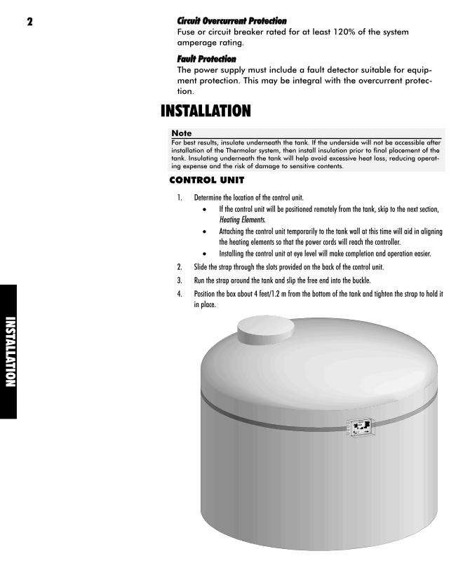
1. Determine the location of the control unit.
• If the control unit will be positioned remotely from the tank, skip to the next section,
Heating Elements.
• Attaching the control unit temporarily to the tank wall at this time will aid in aligning
the heating elements so that the power cords will reach the controller.
• Installing the control unit at eye level will make completion and operation easier.
2. Slide the strap through the slots provided on the back of the control unit.
3. Run the strap around the tank and slip the free end into the buckle.
4. Position the box about 4 feet/1.2 m from the bottom of the tank and tighten the strap to hold it
in place.
NoteFor best results, insulate underneath the tank. If the underside will not be accessible afterinstallation of the Thermolar system, then install insulation prior to final placement of thetank. Insulating underneath the tank will help avoid excessive heat loss, reducing operat-ing expense and the risk of damage to sensitive contents.
2
INST
ALL
ATI
ON
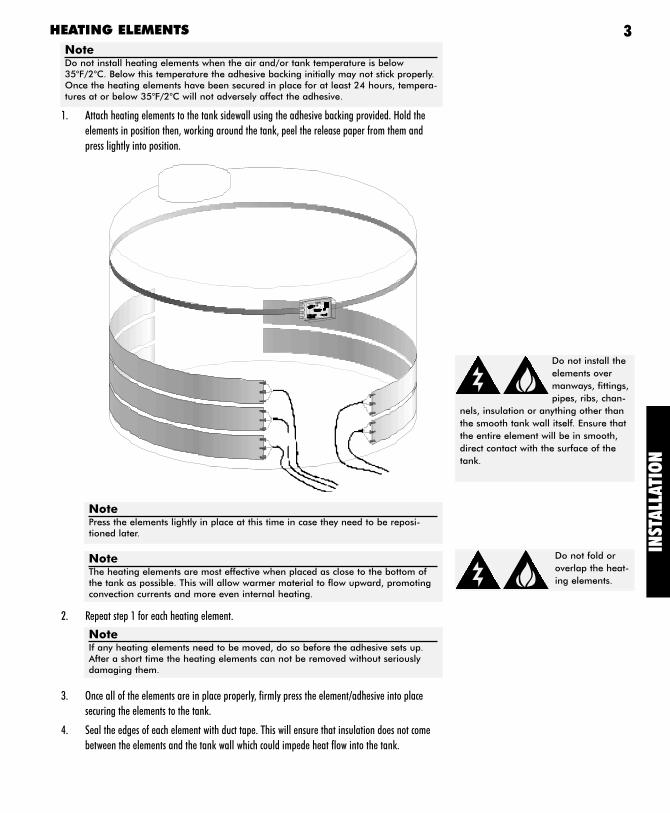
HEATING ELEMENTS
1. Attach heating elements to the tank sidewall using the adhesive backing provided. Hold the
elements in position then, working around the tank, peel the release paper from them and
press lightly into position.
2. Repeat step 1 for each heating element.
3. Once all of the elements are in place properly, firmly press the element/adhesive into place
securing the elements to the tank.
4. Seal the edges of each element with duct tape. This will ensure that insulation does not come
between the elements and the tank wall which could impede heat flow into the tank.
Do not install the
elements over
manways, fittings,
pipes, ribs, chan-
nels, insulation or anything other than
the smooth tank wall itself. Ensure that
the entire element will be in smooth,
direct contact with the surface of the
tank.
Do not fold or
overlap the heat-
ing elements.
NotePress the elements lightly in place at this time in case they need to be reposi-tioned later.
NoteThe heating elements are most effective when placed as close to the bottom ofthe tank as possible. This will allow warmer material to flow upward, promotingconvection currents and more even internal heating.
NoteIf any heating elements need to be moved, do so before the adhesive sets up.After a short time the heating elements can not be removed without seriouslydamaging them.
NoteDo not install heating elements when the air and/or tank temperature is below35°F/2°C. Below this temperature the adhesive backing initially may not stick properly.Once the heating elements have been secured in place for at least 24 hours, tempera-tures at or below 35°F/2°C will not adversely affect the adhesive.
3
INSTA
LLATIO
N
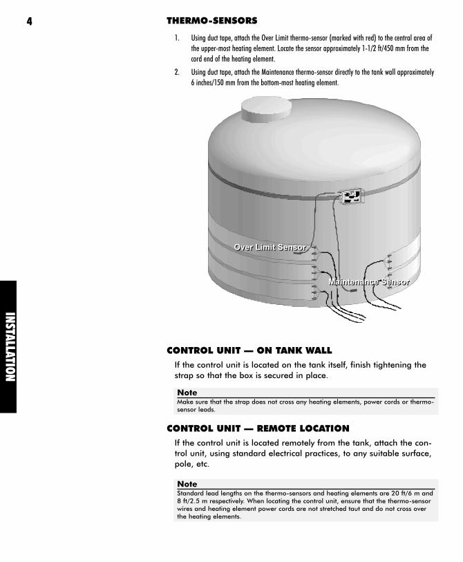
THERMO-SENSORS
1. Using duct tape, attach the Over Limit thermo-sensor (marked with red) to the central area of
the upper-most heating element. Locate the sensor approximately 1-1/2 ft/450 mm from the
cord end of the heating element.
2. Using duct tape, attach the Maintenance thermo-sensor directly to the tank wall approximately
6 inches/150 mm from the bottom-most heating element.
CONTROL UNIT — ON TANK WALL
If the control unit is located on the tank itself, finish tightening thestrap so that the box is secured in place.
CONTROL UNIT — REMOTE LOCATION
If the control unit is located remotely from the tank, attach the con-trol unit, using standard electrical practices, to any suitable surface,pole, etc.
NoteMake sure that the strap does not cross any heating elements, power cords or thermo-sensor leads.
NoteStandard lead lengths on the thermo-sensors and heating elements are 20 ft/6 m and8 ft/2.5 m respectively. When locating the control unit, ensure that the thermo-sensorwires and heating element power cords are not stretched taut and do not cross overthe heating elements.
4
Over Limit SensorOver Limit Sensor
Maintenance SensorMaintenance Sensor
INST
ALL
ATI
ON
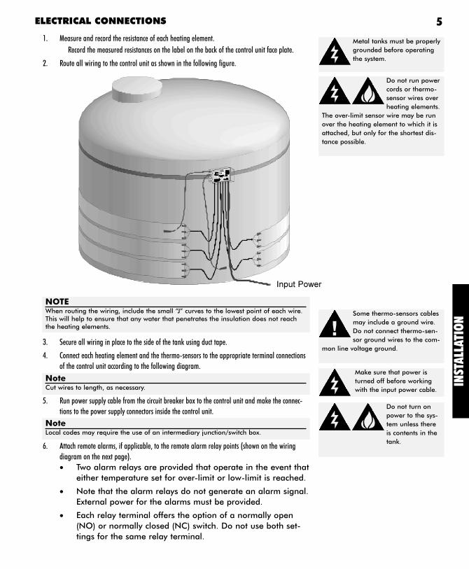
ELECTRICAL CONNECTIONS
1. Measure and record the resistance of each heating element.
Record the measured resistances on the label on the back of the control unit face plate.
2. Route all wiring to the control unit as shown in the following figure.
3. Secure all wiring in place to the side of the tank using duct tape.
4. Connect each heating element and the thermo-sensors to the appropriate terminal connections
of the control unit according to the following diagram.
5. Run power supply cable from the circuit breaker box to the control unit and make the connec-
tions to the power supply connectors inside the control unit.
6. Attach remote alarms, if applicable, to the remote alarm relay points (shown on the wiring
diagram on the next page).
• Two alarm relays are provided that operate in the event thateither temperature set for over-limit or low-limit is reached.
• Note that the alarm relays do not generate an alarm signal.External power for the alarms must be provided.
• Each relay terminal offers the option of a normally open(NO) or normally closed (NC) switch. Do not use both set-tings for the same relay terminal.
Some thermo-sensors cables
may include a ground wire.
Do not connect thermo-sen-
sor ground wires to the com-
mon line voltage ground.
Make sure that power is
turned off before working
with the input power cable.
Do not turn on
power to the sys-
tem unless there
is contents in the
tank.
NoteCut wires to length, as necessary.
NoteLocal codes may require the use of an intermediary junction/switch box.
5
Metal tanks must be properly
grounded before operating
the system.
Do not run power
cords or thermo-
sensor wires over
heating elements.
The over-limit sensor wire may be run
over the heating element to which it is
attached, but only for the shortest dis-
tance possible.
NOTEWhen routing the wiring, include the small “J” curves to the lowest point of each wire.This will help to ensure that any water that penetrates the insulation does not reachthe heating elements.
Input Power
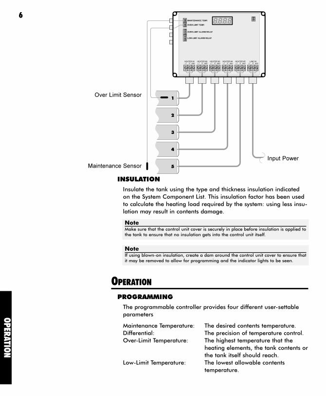
INSULATION
Insulate the tank using the type and thickness insulation indicatedon the System Component List. This insulation factor has been usedto calculate the heating load required by the system: using less insu-lation may result in contents damage.
OPERATION
PROGRAMMING
The programmable controller provides four different user-settableparameters
Maintenance Temperature: The desired contents temperature.Differential: The precision of temperature control.Over-Limit Temperature: The highest temperature that the
heating elements, the tank contents orthe tank itself should reach.
Low-Limit Temperature: The lowest allowable contentstemperature.
OP
ERATIO
N
6
NoteMake sure that the control unit cover is securely in place before insulation is applied tothe tank to ensure that no insulation gets into the control unit itself.
NoteIf using blown-on insulation, create a dam around the control unit cover to ensure thatit may be removed to allow for programming and the indicator lights to be seen.
Input Power
Maintenance Sensor
Over Limit Sensor
OP
ERATI
ON
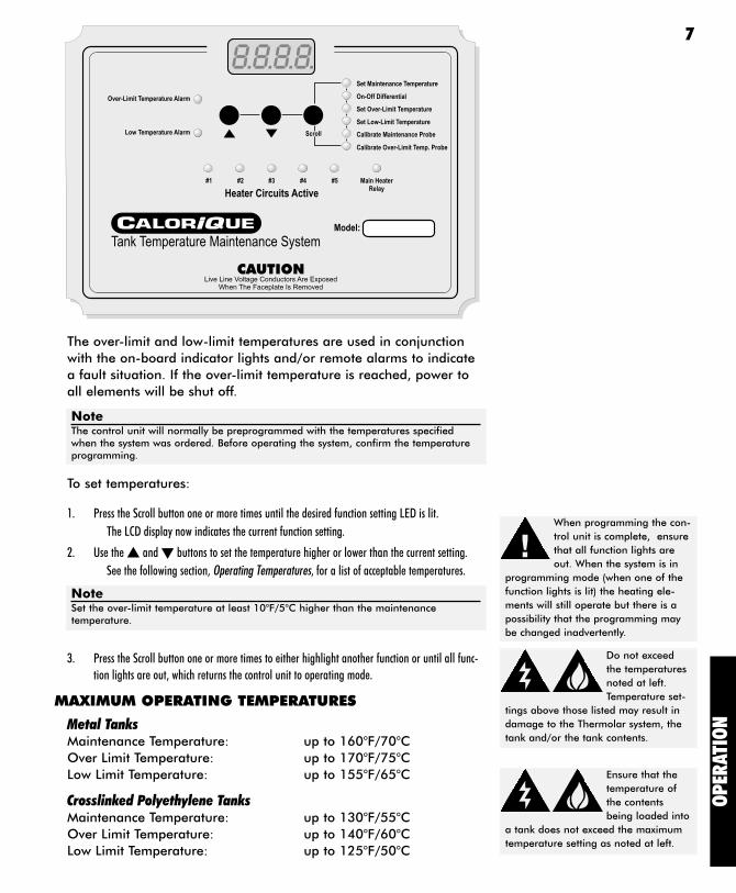
The over-limit and low-limit temperatures are used in conjunctionwith the on-board indicator lights and/or remote alarms to indicatea fault situation. If the over-limit temperature is reached, power toall elements will be shut off.
To set temperatures:
1. Press the Scroll button one or more times until the desired function setting LED is lit.
The LCD display now indicates the current function setting.
2. Use the � and � buttons to set the temperature higher or lower than the current setting.
See the following section, Operating Temperatures, for a list of acceptable temperatures.
3. Press the Scroll button one or more times to either highlight another function or until all func-
tion lights are out, which returns the control unit to operating mode.
MAXIMUM OPERATING TEMPERATURES
Metal TanksMaintenance Temperature: up to 160°F/70°COver Limit Temperature: up to 170°F/75°CLow Limit Temperature: up to 155°F/65°C
Crosslinked Polyethylene TanksMaintenance Temperature: up to 130°F/55°COver Limit Temperature: up to 140°F/60°CLow Limit Temperature: up to 125°F/50°C
When programming the con-
trol unit is complete, ensure
that all function lights are
out. When the system is in
programming mode (when one of the
function lights is lit) the heating ele-
ments will still operate but there is a
possibility that the programming may
be changed inadvertently.
Do not exceed
the temperatures
noted at left.
Temperature set-
tings above those listed may result in
damage to the Thermolar system, the
tank and/or the tank contents.
Ensure that the
temperature of
the contents
being loaded into
a tank does not exceed the maximum
temperature setting as noted at left.
NoteThe control unit will normally be preprogrammed with the temperatures specifiedwhen the system was ordered. Before operating the system, confirm the temperatureprogramming.
NoteSet the over-limit temperature at least 10°F/5°C higher than the maintenance temperature.
7
MAXIMUM OPERATING TEMPERATURES (continued)
Linear Polyethylene Tanks
Maintenance Temperature: up to 120°F/50°COver Limit Temperature: up to 130°F/55°CLow Limit Temperature: up to 115°F/45°C
OPERATION
Under normal operating conditions, no adjustment is necessary. It issuggested that the liquid level within the tank be maintained to atleast the level of the highest heating element. This will ensure thateach heating element is operating at its peak efficiency.
TEMPERATURE ALARMS
User intervention may be required if either the over-limit or low-limitalarm lights are illuminated or if remote alarms (if installed) are acti-vated. Under these circumstances, check for the following indica-tions:
• Does the system or exterior of the tank look damaged in anyway?
Determine the extent of the damage and contact Caloriquetechnical support at (508) 291-4224 for possible correctiveaction.
• Are the heating elements damaged?
To determine if the elements have been damaged:
1. Remove the system from power.
2. Disconnect each heating element from the terminal strip in the control unit.
3. If possible, visually inspect each element for obvious damage.
4. Using an accurate ohm or multimeter, determine the resistance of each element. These readings
should be between the following (depending on voltage):
OP
ERATIO
N
8
NoteIn normal operation, the over-limit temperature alarm and relay may occasionally beactivated. If the over-limit alarm and relay remain on for more than 5 minutes at atime remedial action should be followed.
OP
ERATI
ON
15840 high resistance (120 volt elements) = ————————
rated heat output in watts
13680 low resistance (120 volt elements) = ————————
rated heat output in watts
63360high resistance (240 volt elements) = ————————
rated heat output in watts
54720low resistance (240 volt elements) = ————————
rated heat output in watts
The number of watts is given on the System Components List.
If the resistance reading does not fall within the above numbers, contact Calorique technical
support at (508) 291-4224 for remedies.
• Is the input voltage to the heating elements correct?
• The design voltage is clearly marked on the faceplate of thecontrol unit. Operating heating elements at greater thantheir design voltage can cause overheating of the elementsand tank contents. Operating elements at lower than theirdesign voltage may result in insufficient heat output toproperly maintain contents temperature.
• If the input voltage is not correct: disconnect the systemfrom power and contact Calorique technical support.
• Is there material in the tank?
• An empty tank, or a tank with a contents level below thelevel of the heating elements will, in a short time, result inan over-temperature situation.
• If no: either fill the tank or shut off the heating system untilthe tank has been filled.
• If yes: check to see if the material is thick and sludge-like. Ifit is, then mechanical agitation (mixing) may be required toensure that heat is evenly distributed through the contents.If the material has a low viscosity (like water), proceed tothe next troubleshooting question.
• Is each heating element operating?
Check the Heater Circuits Active indicator lights. When the MainHeater Relay light is illuminated, each heater circuit light shouldalso be lit (unless there is no heating element attached to theparticular circuit). Ensure that any non-operating element is cor-rectly wired into the control unit. If it is (they are): contactCalorique technical support.
• If the above remedies do not fix the problem, call Caloriquetechnical support at (508) 291-4224 for additional help.
9
Calorique Ltd.2380 Cranberry Highway
West Wareham, MA 02576, USA
(508) 291-4224 • (508) 291-2299 fax
Copyright © 1997-2003 Calorique, Ltd. All Rights Reserved. Printed in USA
CM2001 — 2003-04