Embed Size (px)
Citation preview
Loughborough UniversityInstitutional Repository
Thermohydrodynamics ofbidirectional groove dry gas
seals with slip flow
This item was submitted to Loughborough University's Institutional Repositoryby the/an author.
Citation: SU, H., RAHMANI, R. and RAHNEJAT, H., 2016. Thermohy-drodynamics of bidirectional groove dry gas seals with slip flow. InternationalJournal of Thermal Sciences, 110, pp. 270-284.
Additional Information:
• This paper was accepted for publication in the journal International Jour-nal of Thermal Sciences and the definitive published version is availableat http://dx.doi.org/10.1016/j.ijthermalsci.2016.07.011.
Metadata Record: https://dspace.lboro.ac.uk/2134/22270
Version: Accepted for publication
Publisher: c© Elsevier
Rights: This work is made available according to the conditions of the Cre-ative Commons Attribution-NonCommercial-NoDerivatives 4.0 International(CC BY-NC-ND 4.0) licence. Full details of this licence are available at:https://creativecommons.org/licenses/by-nc-nd/4.0/
Please cite the published version.
International Journal of Thermal Sciences, Vol. 110, pp. 270-284, 2016, DOI: 10.1016/j.ijthermalsci.2016.07.011 (Accepted Version)
1
Thermohydrodynamics of Bidirectional Groove Dry Gas Seals with Slip Flow
H. Su 1,2, R. Rahmani 2*, H. Rahnejat 2 1 School of Mechanical Engineering, Northwestern Polytechnical University, Xi’an Shaanxi,
P. R. China 2 Wolfson School of Mechanical and Manufacturing Engineering, Loughborough University,
Loughborough, UK * Corresponding author, Email: [email protected]
Abstract
Thermo-hydrodynamic behaviour of bidirectional dry gas seals with trapezoidal shaped symmetric grooves is studied. A multi-physics model, coupling compressible laminar flow and heat transfer in both the fluid and the solid bodies is used in a multi-physics modelling environment. The multi-physics model also includes slip flow conditions, corresponding to relatively high Knudsen numbers, as well as the effect of asperity interactions on the opposing seal faces. A comparison of the seal performance under isothermal and thermal flow conditions shows the importance of including the thermal effects. The difference in the predicted opening force between isothermal and thermal model can exceed 2.5%, which is equivalent to a force of around 1kN. The importance of designing gas seals to operate at the minimum possible gap to reduce power losses as well as leakage from the contact is highlighted. However, it is shown that there exists a critical minimum gap, below which the power loss in the contact can abruptly increase due to asperity interactions, generating significantly increased operating temperatures.
Keywords: Bidirectional groove dry gas seal; Thermal analysis; Heat transfer; Slip flow; Roughness; Seal performance
Nomenclature
𝐴𝐴𝑠𝑠 Side area of the gap 𝑐𝑐𝑝𝑝 Specific heat capacity of gas at constant pressure 𝑐𝑐𝑠𝑠 Specific heat capacity of seal ring material 𝐷𝐷 Outer diameter of the seal ring (= 2𝑟𝑟𝑜𝑜) 𝑑𝑑 Circumferential width of the middle part of groove at outer rim of seal 𝐸𝐸 Young’s modulus elasticity 𝐸𝐸′ Composite Young’s modulus of elasticity 𝐹𝐹𝑜𝑜 Total opening force (load carrying capacity) 𝐹𝐹𝑜𝑜,ℎ, 𝐹𝐹𝑜𝑜,𝑎𝑎 Opening force due to hydrodynamic reaction and asperity interactions 𝐹𝐹5 2⁄ , 𝐹𝐹2 Statistical functions related to the Greenwood and Tripp asperity model
International Journal of Thermal Sciences, Vol. 110, pp. 270-284, 2016, DOI: 10.1016/j.ijthermalsci.2016.07.011 (Accepted Version)
2
𝑓𝑓 Total friction 𝑓𝑓𝑣𝑣,𝑓𝑓𝑏𝑏 Viscous and boundary friction ℎ Film thickness ℎ0 Minimum film thickness ℎ𝑐𝑐 Critical film thickness ℎ𝑔𝑔,1, ℎ𝑔𝑔,2 Relative depths at the triangular and middle trunk parts of the grooves ℎ𝑡𝑡 Convection heat transfer coefficient ℎ𝑡𝑡,𝑟𝑟, ℎ𝑡𝑡,𝑠𝑠 Convection heat transfer coefficient from outer rims of rotor and stator 𝑘𝑘 Thermal conductivity of the gas 𝑘𝑘𝑠𝑠 Thermal conductivity of seal ring material
Kn Knudsen number (= 𝜂𝜂��𝜋𝜋𝜋𝜋𝑇𝑇𝑔𝑔 2⁄ � 𝑝𝑝ℎ� )
Ma Mach number (= 𝑟𝑟𝑚𝑚𝜔𝜔 �𝛾𝛾𝜋𝜋𝑇𝑇𝑔𝑔⁄ ) �̇�𝑚 Mass flow rate 𝑁𝑁 Rotational speed in RPM 𝑛𝑛� Unit vector in normal direction 𝑛𝑛𝑔𝑔 Number of grooves Nu Nusselt number (= ℎ𝑡𝑡𝐷𝐷 𝑘𝑘⁄ ) 𝑃𝑃𝑙𝑙 Power loss 𝑝𝑝 Pressure 𝑝𝑝𝑖𝑖𝑖𝑖, 𝑝𝑝𝑜𝑜𝑜𝑜𝑡𝑡 Pressure at the inlet (outer radius) and outlet (inner radius) Pr Prandtl number (= 𝑐𝑐𝑝𝑝𝜂𝜂 𝑘𝑘⁄ ) �̇�𝑄𝑙𝑙 Volumetric flow rate of leakage 𝑞𝑞 Heat flux 𝑞𝑞𝑔𝑔,𝑟𝑟, 𝑞𝑞𝑔𝑔,𝑠𝑠 Heat flux from gas to rotor and stator contacting faces 𝑞𝑞𝑤𝑤,𝑟𝑟, 𝑞𝑞𝑤𝑤,𝑠𝑠 Heat flux from at the contacting faces of rotor and stator 𝑞𝑞𝑧𝑧,𝑟𝑟, 𝑞𝑞𝑧𝑧,𝑠𝑠 Heat flux in the axial direction at the back faces of rotor and stator 𝑞𝑞𝑟𝑟,𝑞𝑞𝜃𝜃,𝑞𝑞𝑧𝑧 Heat flux in radial, circumferential and axial directions 𝜋𝜋 Specific gas constant Re Reynolds number (= 𝜌𝜌𝑟𝑟𝑚𝑚𝜔𝜔ℎ 𝜂𝜂⁄ ) Re𝐷𝐷 Reynolds number for convective heat transfer calculations (= 𝜌𝜌𝑟𝑟𝑜𝑜𝜔𝜔𝐷𝐷 𝜂𝜂⁄ ) 𝑟𝑟 Radius 𝑟𝑟𝑖𝑖, 𝑟𝑟𝑜𝑜 Inner and outer radius of the seal 𝑟𝑟𝑔𝑔1,𝑟𝑟𝑔𝑔2 Radius of the bottom rim of lower and upper part of seal groove 𝑟𝑟𝑚𝑚 Average radius 𝑟𝑟,𝜃𝜃,𝑧𝑧 Radial ,circumferential and axial (cylindrical) coordinates �̂�𝑟,𝜃𝜃�,�̂�𝑧 Unit vectors in radial, circumferential and axial directions 𝑇𝑇𝑔𝑔, 𝑇𝑇𝑠𝑠 Gas and solid body temperature distribution 𝑇𝑇𝑔𝑔,0, 𝑇𝑇𝑠𝑠,0 Inlet gas temperature and initial surface temperature of the seal rings 𝑇𝑇𝑔𝑔,𝑖𝑖 Gas temperature at the inlet (outer radius) 𝑇𝑇𝑔𝑔,𝑟𝑟, 𝑇𝑇𝑔𝑔,𝑠𝑠 Gas temperature near rotor and stator contact face surfaces 𝑇𝑇𝑤𝑤 Temperature of the solid wall in contact with sealing gas
International Journal of Thermal Sciences, Vol. 110, pp. 270-284, 2016, DOI: 10.1016/j.ijthermalsci.2016.07.011 (Accepted Version)
3
𝑇𝑇𝑤𝑤,𝑟𝑟, 𝑇𝑇𝑤𝑤,𝑠𝑠 Wall temperature at rotor and stator contact surfaces 𝑡𝑡𝑟𝑟, 𝑡𝑡𝑠𝑠 Axial thickness of the rotating and stationary seals 𝑢𝑢�⃑ 𝑠𝑠 Slip velocity vector 𝑉𝑉�⃑ Velocity vector in cylindrical coordinates (𝑉𝑉�⃑ = 𝑉𝑉𝑟𝑟�̂�𝑟 + 𝑉𝑉𝜃𝜃𝜃𝜃� + 𝑉𝑉𝑧𝑧�̂�𝑧) 𝑉𝑉𝑔𝑔 Gas velocity magnitude
Greek symbols
𝛼𝛼1, α2 Spiral groove angle at upper and bottom parts of seal groove 𝛼𝛼𝑣𝑣 Tangential momentum accommodation coefficient 𝛾𝛾 Heat capacity ratio ∆𝑔𝑔 Angle of an annular sector comprising one complete groove 𝜖𝜖 Numerical damping coefficients 𝜀𝜀𝑠𝑠 Coefficient of thermal expansion for seal ring 𝜁𝜁𝑇𝑇 Temperature jump coefficient 𝜂𝜂 Dynamic viscosity of gas 𝜅𝜅 Average asperity tip radius 𝜆𝜆 Molecular mean free path 𝜆𝜆𝑠𝑠 Stribeck film ratio parameter 𝜈𝜈 Poisson’s ratio 𝜉𝜉 Asperity density per unit area of the contact 𝜌𝜌 Gas density 𝜌𝜌𝑠𝑠 Density of seal ring material 𝜎𝜎 Standard deviation of the surface roughness 𝜎𝜎𝑠𝑠,𝜎𝜎𝑇𝑇 Viscous slip and thermal slip coefficients 𝜍𝜍 Coefficient of boundary shear strength at the tip of asperities 𝜏𝜏̅ Shear stress tensor 𝜏𝜏𝑣𝑣 Viscous shear Φ Heat source term 𝜑𝜑 Angle of an annular sector of the seal containing a single groove 𝜔𝜔 Angular velocity of rotation
Superscripts n Iteration step T Transpose of tensor
Subscripts
1,2 Rotor, stator c Combined L,R Left and Right hand sides
Abbreviations
AFM Atomic Force Microscopy CFD Computational Fluid Dynamics DLC Diamond-Like Carbon
International Journal of Thermal Sciences, Vol. 110, pp. 270-284, 2016, DOI: 10.1016/j.ijthermalsci.2016.07.011 (Accepted Version)
4
DNS Direct Numerical Simulation FEM Finite Element Method GUI Graphical User Interface LFM Lateral Force Microscopy RMS Root Mean Square RPM Revolutions per Minute SiC Silicon Carbide
1. Introduction
Non-contacting dry gas seals are widely used in multi-stage compressors such as those employed in the oil and gas industry. Grooves of various shapes have been used on the seal face to induce the required hydrodynamic lift and enhance contact stiffness. This is an additional load carrying contribution to the inherent hydrostatic pressures which also maintain a desired gap between the sealing surfaces. Maintaining a gap is critical in minimising wear and ensuring the reliable operation of the gas seal.
The unidirectional spiral groove gas seals have been the focus of research for many years, unlike the bidirectional seals. The advantages of bidirectional seals is their ability in creating a hydrodynamic lift irrespective of the direction of rotation of the shaft. This feature brings about many operational and maintenance cost benefits (Kowalski and Basu [1]). For instance, some compressors without upgraded control system cannot prevent reverse rotation during shutdown. These would benefit from the lift ability of bidirectional seals. Otherwise, Implementation of preventative reverse rotation control systems can add to the maintenance costs of many existing installations. In addition, the failure of one or more of the adapted compressor control system components can also cause some reverse rotation of the compressor rotor. In such cases and in the absence of hydrodynamic pressure built-up, the hydrostatic pressure alone is not usually sufficient to support the applied closing force, thus causing the seal faces to collapse.
There is a dearth reported research on the performance of bidirectional gas seals. Basu [2] investigated the performance of various groove geometries for bidirectional seals, including the radial or parallel groove profiles. Takeuchi et al [3] introduced bidirectional tapered-step grooves, and a three-row spiral groove configuration was presented by Wang [4]. Goldswain and Do Boer Hignett [5] patented a trapezoidal shape groove configuration for bidirectional seal applications.
Most of studies of isothermal continuum fluid flow conditions in the analysis of bidirectional gas seals (Bonneau et al [6], Zirkelback [7], Xu et al [8], Shahin et al [9], Wang et al [10] and Su et al [11]). Ruan et al [12] showed that in striving to reduce leakage, a tighter seal gap should be used. However, the required minimum gap often can be of the order of seal face roughness, where the probability of direct asperity contact on the opposing surfaces becomes inevitable. Consequently, this would lead to increased frictional losses, generated heat, wear and durability of the seals. Hitherto, such effects have not been addressed in the study of the gas seals to any great detail. Furthermore, with very thin fluid films, the molecular mean free path is comparable with the fluid film thickness itself, thus the assumption of continuum flow
International Journal of Thermal Sciences, Vol. 110, pp. 270-284, 2016, DOI: 10.1016/j.ijthermalsci.2016.07.011 (Accepted Version)
5
with no slip boundary conditions fails to describe the real physical conditions. Therefore, a modified set of governing equations or associate boundary conditions are required to represent the prevailing conditions (Ruan [13]).
Brunetiere and Modolo [14] showed that with ultra-thin film gaps, sealing performance can be affected by the thermal effects originated from the direct asperity contacts in mixed regime of lubrication. In such applications, where the working fluid is liquid, normally reduced viscosity under high operating temperatures reduce the load carrying capacity of the contact and promote seal seizure. On the other hand, in the case of gas seals and under similar working conditions, the internal heating originated from both viscous and boundary shear can increase the viscosity of gas; resulting in an increase in film thickness, promoting leakage.
Most research; including the aforementioned, have focused on the understanding of the behaviour of unidirectional grooved dry gas seals. For instance, Ruan [13] and Wang and Zhang [15] investigated the effect of slip flow in the spiral groove dry gas seals. Thomas et al [16] and Wang et al [17] included the effect of generated heat on the seal performance, but excluding the effect of any asperity interactions. However, Ruan et al [12] presented a simplified 1D mixed regime of lubrication model for axisymmetric seal contacts with no included grooves. They also investigated the effect of temperature on contact deformation by assuming linear temperature and deformation profiles. Furthermore, they did not include the slip flow conditions in their model, where the gap between the seal faces was of the same order as their roughness. Therefore, there is a need to for a more comprehensive analysis, which should take into account a 2D contact model, incorporating slip flow boundary conditions, asperity interactions in thinner gaps and with the inclusion of thermal effects. Appropriate boundary conditions, taking into account the thermal behaviour of the fluid and solid through a multi-physics approach should also be employed.
This paper extends the previous work of Su et al [11] for the case of bidirectional dry gas seals through inclusion of thermal analysis on the seal performance. Performance of bidirectional gas seals with symmetric trapezoidal grooves under thermal conditions is studied. The multi-physics thermally-coupled model, including fluid flow, heat transfer in both fluid and solids is thus established. Additionally, the effect of slip flow and mixed regime of lubrication are considered. Such an approach has not hitherto been reported in literature. Real measured data from gas seals of compressors in gas conveying pipelines is used in the analysis. The results of isothermal and thermal analyses are compared in order to evaluate the effect of thermal deformation on the seal performance metrics.
2. Numerical Model
2.1. Flow conditions
For a typical gas seal configuration, the flow of gas through the contact and the associated frictional losses is expected to increase with elevated temperature of the fluid, as well as the surrounding solid boundaries. These increased losses are due to heat convection and conduction processes. With the included surface grooves, the generated frictional power loss
International Journal of Thermal Sciences, Vol. 110, pp. 270-284, 2016, DOI: 10.1016/j.ijthermalsci.2016.07.011 (Accepted Version)
6
is expected to be non-uniform, which may cause thermal distortion of the solid bodies. Simultaneously, the temperature of the entrant gas flow into the contact rises because of the relatively hotter surfaces, which in turn can increase the viscosity of the gas, thus the viscous frictional losses. However, increased gas viscosity is expected to increase the load carrying capacity and result in a larger gap between the sealing surfaces. A larger gap would reduce the chance of direct boundary interaction, decreasing the power loss due to boundary friction. There is also the increased chance of gas leakage with increasing gaps. Therefore, there are complex interactions in coupled thermal conditions, gas flow, mechanical distortion and surface interactions, requiring a representative multi-physics analysis.
The choice of a model and the associated boundary conditions is based on the physical operating conditions; temperature, contact pressure, rotational speed, and the designed seal face gap. Reynolds’, Knudsen and Mach numbers determine the type of gas flow, in terms of flow compressibility, laminarity and the need for any slip flow boundary conditions.
Reynolds’ number indicates the permissible range for an assumed laminar flow. It can be shown that the Reynolds’ number remains below 4000 in the current analysis. This indicates that the conditions studied here fall largely in the realm of the laminar gas flow, particularly for low speed operations with fairly small gaps. This is the range of interest in the current study and an increasing trend in practice, where there is a greater probability of direct asperity contacts. However, a more accurate analysis may need to consider the turbulent flow conditions and use an appropriate turbulent model. These conditions would lead to higher film thickness, lower load carrying capacity and potential leakage.
The gas density, in general, is a function of temperature and pressure. For lower Mach numbers, incompressible flow conditions may be assumed. The typical Mach numbers encountered fall below 0.25, yielding an incompressible gas flow. However, for the sake of generality, the fluid flow is considered to be compressible throughout this study, whilst the effect of the compressive heating is neglected.
For gas flow the Knudsen number is commonly used to ascertain any degree of gas rarefaction. For: Kn < 0.01, a continuum flow with no slip boundary conditions may be assumed, whilst for 0.01 ≤ Kn < 15, requires slip flow boundary conditions (Szeri [18]). For some of the studied cases in this paper, the Knudsen number can take values greater than 0.01 and hence, slip boundary conditions are defined. It should also be noted that the inspection of the Knudsen number in this study does not predict any molecular flow regime conditions.
2.2. Contact geometry
The studied seal pair constitutes a nominally flat working surface for the stationary ring (stator) and a rotating ring (rotor), containing symmetric trapezoidal shaped grooves. Due to the symmetrical distribution of the grooves around the seal face, one can simulate an annular slab comprising a single groove feature. This is a common computational approach (Ruan [13], Shahin et al [9], Wang et al [17] as well as other similar works).
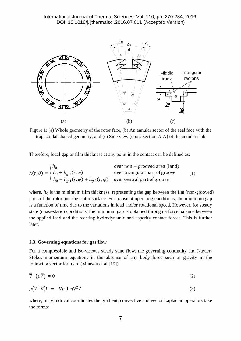
Figure 1 depicts the schematic profile of a single groove computational domain.
International Journal of Thermal Sciences, Vol. 110, pp. 270-284, 2016, DOI: 10.1016/j.ijthermalsci.2016.07.011 (Accepted Version)
7
(a) (b) (c)
Figure 1: (a) Whole geometry of the rotor face, (b) An annular sector of the seal face with the trapezoidal shaped geometry, and (c) Side view (cross-section A-A) of the annular slab
Therefore, local gap or film thickness at any point in the contact can be defined as:
ℎ(𝑟𝑟, 𝜃𝜃) = �ℎ0 over non − grooved area (land)ℎ0 + ℎ𝑔𝑔,1(𝑟𝑟,𝜑𝜑) over triangular part of groove ℎ0 + ℎ𝑔𝑔,1(𝑟𝑟,𝜑𝜑) + ℎ𝑔𝑔,2(𝑟𝑟,𝜑𝜑) over central part of groove
(1)
where, ℎ0 is the minimum film thickness, representing the gap between the flat (non-grooved) parts of the rotor and the stator surface. For transient operating conditions, the minimum gap is a function of time due to the variations in load and/or rotational speed. However, for steady state (quasi-static) conditions, the minimum gap is obtained through a force balance between the applied load and the reacting hydrodynamic and asperity contact forces. This is further later.
2.3. Governing equations for gas flow
For a compressible and iso-viscous steady state flow, the governing continuity and Navier-Stokes momentum equations in the absence of any body force such as gravity in the following vector form are (Munson et al [19]):
∇��⃑ ∙ �𝜌𝜌𝑉𝑉�⃑ � = 0 (2)
𝜌𝜌�𝑉𝑉�⃑ ∙ ∇��⃑ �𝑉𝑉�⃑ = −∇��⃑ 𝑝𝑝 + 𝜂𝜂∇��⃑ 2𝑉𝑉�⃑ (3)
where, in cylindrical coordinates the gradient, convective and vector Laplacian operators take the forms:
ri ro
rg2
rg1
d∆g
α1 α2
ϕ
Middle trunk
Triangular regions
International Journal of Thermal Sciences, Vol. 110, pp. 270-284, 2016, DOI: 10.1016/j.ijthermalsci.2016.07.011 (Accepted Version)
8
∇��⃑ ≡ � 𝜕𝜕𝜕𝜕𝑟𝑟
+ 1𝑟𝑟� �̂�𝑟 + 1
𝑟𝑟𝜕𝜕𝜕𝜕𝜃𝜃𝜃𝜃� + 𝜕𝜕
𝜕𝜕𝑧𝑧�̂�𝑧 (4)
𝑉𝑉�⃑ ∙ ∇��⃑ ≡ 𝑉𝑉𝑟𝑟𝜕𝜕𝜕𝜕𝑟𝑟
+ 𝑉𝑉𝜃𝜃1𝑟𝑟𝜕𝜕𝜕𝜕𝜃𝜃
+ 𝑉𝑉𝑧𝑧𝜕𝜕𝜕𝜕𝑧𝑧
(5)
∇��⃑ 2𝑉𝑉�⃑ ≡ �∇2𝑉𝑉𝑟𝑟 −1𝑟𝑟2𝑉𝑉𝑟𝑟 −
2𝑟𝑟2
𝜕𝜕𝑉𝑉𝜃𝜃𝜕𝜕𝜃𝜃� �̂�𝑟 + �∇2𝑉𝑉𝜃𝜃 −
1𝑟𝑟2𝑉𝑉𝜃𝜃 + 2
𝑟𝑟2𝜕𝜕𝑉𝑉𝑟𝑟𝜕𝜕𝜃𝜃� 𝜃𝜃� + ∇2𝑉𝑉𝑧𝑧�̂�𝑧 (6)
In the last equation, the ordinary Laplacian operator in cylindrical coordinates is defined as:
∇2≡ 1𝑟𝑟𝜕𝜕𝜕𝜕𝑟𝑟�𝑟𝑟 𝜕𝜕
𝜕𝜕𝑟𝑟� + 1
𝑟𝑟2𝜕𝜕2
𝜕𝜕𝜃𝜃2+ 𝜕𝜕2
𝜕𝜕𝑧𝑧2 (7)
In addition, the energy equation for the fluid flow with variable thermal conductivity and specific heat capacity under steady state conditions, neglecting the effect of heat-induced compressibility becomes:
𝜌𝜌�𝑉𝑉�⃑ ∙ ∇��⃑ ��𝑐𝑐𝑝𝑝𝑇𝑇𝑔𝑔� − ∇��⃑ ∙ �𝑘𝑘∇��⃑ 𝑇𝑇𝑔𝑔� = Φ (8)
where, Φ is the heat source term, which mainly originates from the frictional losses in the contact.
2.4. Constitutive equations for gas properties
The sealing gas is considered to have the properties of air, thus following the ideal gas behaviour; i.e. 𝜌𝜌 = 𝑝𝑝 𝜋𝜋𝑇𝑇𝑔𝑔⁄ . The thermal and mechanical properties of the gas are considered to be variable with temperature only. Hence, the following empirical relationships obtained through data fitting are used to describe the variations of gas dynamic viscosity, 𝜂𝜂, thermal conductivity, 𝑘𝑘, and specific heat capacity at constant pressure, 𝑐𝑐𝑝𝑝, with temperature [20]:
𝜂𝜂(𝑇𝑇) = −8.38278 × 10⁻⁷ + 8.35717 × 10⁻⁸𝑇𝑇𝑔𝑔 − 7.69430 × 10⁻¹¹𝑇𝑇𝑔𝑔2 + 4.64373 ×10⁻¹⁴𝑇𝑇𝑔𝑔3 − 1.06586 × 10⁻¹⁷𝑇𝑇𝑔𝑔4 (9)
𝑘𝑘(𝑇𝑇) = −2.27584 × 10⁻³ + 1.15480 × 10⁻⁴𝑇𝑇𝑔𝑔 − 7.90253 × 10⁻⁸𝑇𝑇𝑔𝑔2 + 4.11702 ×10⁻¹¹𝑇𝑇𝑔𝑔3 − 7.43864 × 10⁻¹⁵𝑇𝑇𝑔𝑔4 (10)
𝑐𝑐𝑝𝑝(𝑇𝑇) = +1.04764 × 10³ − 3.72589 × 10⁻¹𝑇𝑇𝑔𝑔 + 9.45304 × 10⁻⁴𝑇𝑇𝑔𝑔2 − 6.02409 ×10⁻⁷𝑇𝑇𝑔𝑔3 + 1.28590 × 10⁻¹⁰𝑇𝑇𝑔𝑔4 (11)
At each computational iterative step the gas properties are updated, based on the calculated gag temperature at the instantaneous iteration step until a steady state solution is achieved.
2.5. Slip flow conditions
For the cases where: Kn ≥ 0.01, the slip flow conditions are considered. In the slip flow regime, the Navier-Stokes equations can be used to model the flow of the gas, except within a thin layer of rarefied gas adherent to the solid boundaries; known as the Knudsen layer
International Journal of Thermal Sciences, Vol. 110, pp. 270-284, 2016, DOI: 10.1016/j.ijthermalsci.2016.07.011 (Accepted Version)
9
(Fukui and Kaneko [21]). The effect of Knudsen layer on the continuum part of the flow can be modelled by modifying the boundary conditions for the Navier-Stokes equations. Using the generalised form of the Maxwell’s definition, the slip boundary conditions for the velocity and temperature at the solid walls are described as [22]:
𝑢𝑢�⃑ 𝑠𝑠 = 𝜎𝜎𝑠𝑠𝜆𝜆𝜂𝜂
[𝜏𝜏̅𝑛𝑛� − (𝑛𝑛�𝑇𝑇𝜏𝜏̅𝑛𝑛�)𝑛𝑛�] + 𝜎𝜎𝑇𝑇𝜂𝜂𝜌𝜌𝑇𝑇�∇��⃑ 𝑇𝑇𝑤𝑤 − �𝑛𝑛� ∙ ∇��⃑ 𝑇𝑇𝑤𝑤�𝑛𝑛�� (12)
𝑇𝑇𝑤𝑤 = 𝑇𝑇𝑔𝑔 − 𝜁𝜁𝑇𝑇𝜆𝜆 �𝑛𝑛� ∙ ∇��⃑ 𝑇𝑇𝑔𝑔�𝑤𝑤� (13)
where, the second term on the right-hand-side of equation (12) accounts for thermal creep, generating slip velocity in the fluid flow opposing the direction of the tangential heat flux (Gad-el-Hak [23]). Furthermore, in the equations above, u�⃑ s is the slip velocity vector, 𝑛𝑛� is the contact normal to the boundary solids, 𝜏𝜏̅ is the viscous shear stress tensor, 𝜆𝜆 is the molecular mean free path, 𝜂𝜂 is the gas dynamic viscosity and 𝜌𝜌, its the density. 𝑇𝑇 is the gas temperature and 𝑇𝑇𝑤𝑤 is the solid wall temperature in contact with the sealing gas flow. In addition, the parameters; 𝜎𝜎𝑠𝑠 , 𝜎𝜎𝑇𝑇 and 𝜁𝜁𝑇𝑇 represent viscous slip, thermal slip and temperature jump coefficients within the generalised Maxwellian model, and are defined as [22]:
𝜎𝜎𝑠𝑠 = 2−𝛼𝛼𝑣𝑣𝛼𝛼𝑣𝑣
, 𝜎𝜎𝑇𝑇 = 34, and 𝜁𝜁𝑇𝑇 = 𝜎𝜎𝑠𝑠
2𝛾𝛾𝛾𝛾+1
𝑘𝑘𝜂𝜂𝑐𝑐𝑝𝑝
(14)
where, 𝛼𝛼𝑣𝑣 is the dimensionless coefficient of tangential momentum accommodation. This is typically dependent on the fluid and solid body types and the surface finish, and is determined experimentally. It can generally vary between 0.2 to 1.0 (Gad-el-Hak [23] and Karniadakis et al [24]). The lower limit is for exceptionally smooth surfaces and the upper limit is used for most practical engineering surfaces (Gad-el-Hak [23]). Considering the roughness of the surfaces used in this study, a value of 0.9 is employed for the coefficient of tangential momentum accommodation.
2.6. Boundary conditions for the fluid flow
The boundary conditions for pressure at the inner and outer rim radii and along the circumferential and axial directions of the seal are considered to remain constant as:
𝑝𝑝(𝑟𝑟𝑖𝑖,𝜃𝜃, 𝑧𝑧) = 𝑝𝑝𝑜𝑜𝑜𝑜𝑡𝑡, and 𝑝𝑝(𝑟𝑟𝑜𝑜 ,𝜃𝜃, 𝑧𝑧) = 𝑝𝑝𝑖𝑖𝑖𝑖 (15)
Furthermore, periodic-type boundary conditions are assumed at the two lateral sides of the annular sector (slab) of the seal. As a result the pressure gradient at any radial position over the circumferential boundaries is set zero. In addition, the continuity of flow condition determines that the mass flow into and out of the contact in the circumferential direction should equate, thus [25-26]:
𝜕𝜕𝑝𝑝𝜕𝜕𝜃𝜃�
(𝑟𝑟,𝜃𝜃𝐿𝐿)= 𝜕𝜕𝑝𝑝
𝜕𝜕𝜃𝜃�
(𝑟𝑟,𝜃𝜃𝑅𝑅)= 0 (16)
International Journal of Thermal Sciences, Vol. 110, pp. 270-284, 2016, DOI: 10.1016/j.ijthermalsci.2016.07.011 (Accepted Version)
10
�̇�𝑚(𝑟𝑟,𝜃𝜃𝐿𝐿) = �̇�𝑚(𝑟𝑟,𝜃𝜃𝑅𝑅) (17)
2.7. Heat conduction in the solid bodies
The temperature distribution in the solid bodies is governed by heat conduction. To provide a complete thermal model, this requires the solution of heat conduction in the solids (i.e. for the rotating and stationary seal faces with coupled thermal boundary conditions between the fluid and the solid boundaries). In the current analysis the heat transfer due to radiation is neglected and therefore, the focus is put upon conductive heat transfer. In addition, both stator and rotor are considered to be homogenous and isotropic solids.
The heat conduction equation for the rotor without an internal heat source in cylindrical coordinates is (Noda et al [27]):
𝜌𝜌𝑠𝑠𝑐𝑐𝑠𝑠𝜔𝜔𝜕𝜕𝑇𝑇𝑠𝑠𝜕𝜕𝜃𝜃
= 𝑘𝑘𝑠𝑠∇2𝑇𝑇𝑠𝑠 (18)
For the stator, the heat condition reduces to its steady state form, thus:
∇2𝑇𝑇𝑠𝑠 = 0 (19)
2.8. Thermal boundary conditions and gas/solid temperature coupling
The outer rim of the rotor and the stator rings are exposed to the ambient and the compressor chamber fluids respectively. In both cases, there is a relative motion between the solid body and the surrounding fluid. Therefore, forced convective heat transfer for the outer rims is considered. The convection heat transfer coefficient is defined as (Incropera et al [28]):
ℎ𝑡𝑡 = Nu𝑘𝑘𝐷𝐷
(20)
where, 𝑘𝑘 is the thermal conductivity of the surrounding fluid, which is assumed to be air, 𝐷𝐷 = 2𝑟𝑟𝑜𝑜 is the diameter of the seal ring and Nu is the Nusselt number. The surface-averaged Nusselt number for forced convective heat transfer for a cylinder in crossflow is given by the Churchill-Bernstein equation (Incropera et al [28]):
Nu = 0.3 + 0.62Re𝐷𝐷1 2⁄ Pr1 3⁄
�1+(0.4 Pr⁄ )2 3⁄ �1 4⁄ �1 + � Re𝐷𝐷282000
�5 8⁄
�4 5⁄
where, PrRe𝐷𝐷 ≥ 0.2 (21)
In this equation, Re𝐷𝐷 is the Reynolds’ number and is defined, based on the cylinder diameter as the characteristic length. In addition, in the case of the rotor disc, the characteristic speed is considered to be 𝑟𝑟𝑜𝑜𝜔𝜔. For the case of the stator, the characteristic speed is considered to be the gas flush speed in the chamber, which in this case is taken as 5m/s, based on the recommendation by Wang et al [17].
International Journal of Thermal Sciences, Vol. 110, pp. 270-284, 2016, DOI: 10.1016/j.ijthermalsci.2016.07.011 (Accepted Version)
11
In the inner rim of the seal rings, adiabatic boundary conditions are used. In reality, the inner rims of the seal rings are connected to the supporting shafts which can further aid heat transfer away from the gas seal rings. Therefore, a more realistic boundary condition needs to take into account the entire assembly, which is beyond the scope of the current analysis. Therefore, at the inner rims:
−𝑛𝑛�. 𝑞𝑞𝑟𝑟 = 0 (22)
Periodic heat boundary conditions are assumed for the two lateral faces of the annular sector of both the rotor and the stator in the circumferential direction. These boundary conditions are defined as:
−𝑛𝑛�𝐿𝐿𝑞𝑞𝜃𝜃𝐿𝐿 = 𝑛𝑛�𝑅𝑅𝑞𝑞𝜃𝜃𝑅𝑅, and 𝑇𝑇𝑠𝑠,𝐿𝐿 = 𝑇𝑇𝑠𝑠,𝑅𝑅 (23)
where, 𝑞𝑞𝜃𝜃 denotes the heat flux from the solid surface at either sides of the annular sector in the circumferential direction.
For back surfaces of both the seal rings in the axial direction, adiabatic boundary conditions are assumed, which are defined as:
𝑛𝑛�. 𝑞𝑞𝑧𝑧,𝑟𝑟 = −𝑛𝑛�. 𝑞𝑞𝑧𝑧,𝑠𝑠 = 0 (24)
The boundary conditions for the surfaces of the seal rings contact faces constitute the heat flux produced due to contact friction. The heat generated due to viscous shear of the fluid and any asperity interaction under given operational conditions is transferred through the fluid to the boundary solids. The heat flow from the gas should be coupled to those in the solid rotor and stator by applying the continuity of heat flux condition and conformance of temperatures at the interface. In other words, the temperature and heat flux in the interface of fluid and solid should be the same, thus:
𝑞𝑞𝑤𝑤,𝑟𝑟 = 𝑞𝑞𝑔𝑔,𝑟𝑟, 𝑞𝑞𝑤𝑤,𝑠𝑠 = 𝑞𝑞𝑔𝑔,𝑠𝑠, and 𝑇𝑇𝑤𝑤,𝑟𝑟 = 𝑇𝑇𝑔𝑔,𝑟𝑟, 𝑇𝑇𝑤𝑤,𝑠𝑠 = 𝑇𝑇𝑔𝑔,𝑠𝑠 (25)
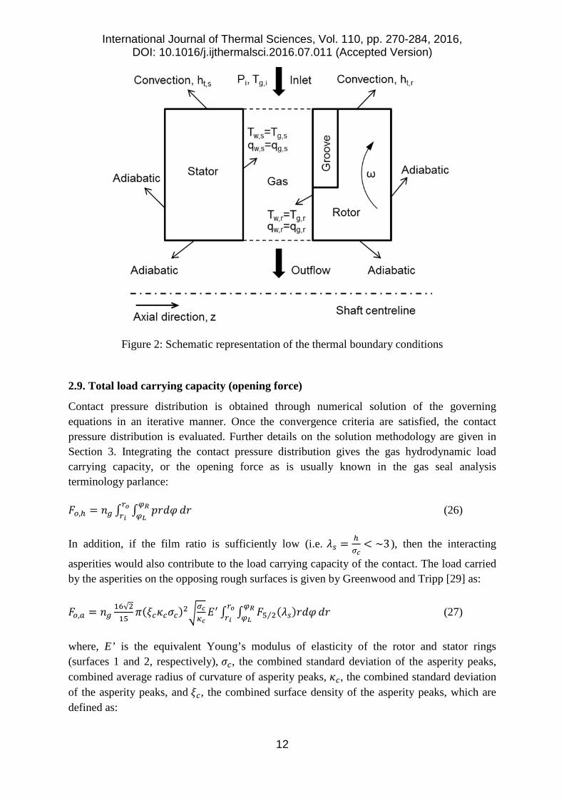
Figure 2 below is a schematic representation of the implemented thermal boundary conditions in the current analysis.
International Journal of Thermal Sciences, Vol. 110, pp. 270-284, 2016, DOI: 10.1016/j.ijthermalsci.2016.07.011 (Accepted Version)
12
Figure 2: Schematic representation of the thermal boundary conditions
2.9. Total load carrying capacity (opening force)
Contact pressure distribution is obtained through numerical solution of the governing equations in an iterative manner. Once the convergence criteria are satisfied, the contact pressure distribution is evaluated. Further details on the solution methodology are given in Section 3. Integrating the contact pressure distribution gives the gas hydrodynamic load carrying capacity, or the opening force as is usually known in the gas seal analysis terminology parlance:
𝐹𝐹𝑜𝑜,ℎ = 𝑛𝑛𝑔𝑔 ∫ ∫ 𝑝𝑝𝑟𝑟𝑑𝑑𝜑𝜑𝜑𝜑𝑅𝑅𝜑𝜑𝐿𝐿
𝑑𝑑𝑟𝑟𝑟𝑟𝑜𝑜𝑟𝑟𝑖𝑖
(26)
In addition, if the film ratio is sufficiently low (i.e. 𝜆𝜆𝑠𝑠 = ℎ𝜎𝜎𝑐𝑐
< ~3), then the interacting
asperities would also contribute to the load carrying capacity of the contact. The load carried by the asperities on the opposing rough surfaces is given by Greenwood and Tripp [29] as:
𝐹𝐹𝑜𝑜,𝑎𝑎 = 𝑛𝑛𝑔𝑔16√215
𝜋𝜋(𝜉𝜉𝑐𝑐𝜅𝜅𝑐𝑐𝜎𝜎𝑐𝑐)2�𝜎𝜎𝑐𝑐𝜅𝜅𝑐𝑐𝐸𝐸′ ∫ ∫ 𝐹𝐹5 2⁄ (𝜆𝜆𝑠𝑠)𝑟𝑟𝑑𝑑𝜑𝜑𝜑𝜑𝑅𝑅
𝜑𝜑𝐿𝐿𝑑𝑑𝑟𝑟𝑟𝑟𝑜𝑜
𝑟𝑟𝑖𝑖 (27)
where, E’ is the equivalent Young’s modulus of elasticity of the rotor and stator rings (surfaces 1 and 2, respectively), 𝜎𝜎𝑐𝑐, the combined standard deviation of the asperity peaks, combined average radius of curvature of asperity peaks, 𝜅𝜅𝑐𝑐, the combined standard deviation of the asperity peaks, and 𝜉𝜉𝑐𝑐, the combined surface density of the asperity peaks, which are defined as:
International Journal of Thermal Sciences, Vol. 110, pp. 270-284, 2016, DOI: 10.1016/j.ijthermalsci.2016.07.011 (Accepted Version)
13
1𝐸𝐸′
= 1−𝜈𝜈12
𝐸𝐸1+ 1−𝜈𝜈22
𝐸𝐸2 𝜎𝜎𝑐𝑐 = �𝜎𝜎12 + 𝜎𝜎22, 1
𝑘𝑘𝑐𝑐= 1
𝜅𝜅1+ 1
𝜅𝜅2, and 𝜉𝜉𝑐𝑐 = (𝜉𝜉1 + 𝜉𝜉2) 2⁄
(28)
In addition, the statistical function 𝐹𝐹5 2⁄ can be approximated using a 5th-order polynomial curve fit as (Gohar and Rahnejat [30]):
𝐹𝐹5/2(𝜆𝜆𝑠𝑠) = max{−0.0046𝜆𝜆𝑠𝑠5 + 0.0574𝜆𝜆𝑠𝑠4 − 0.2958𝜆𝜆𝑠𝑠3 + 0.7844𝜆𝜆𝑠𝑠2 − 1.0776𝜆𝜆𝑠𝑠 + 0.616,0} (29)
The above equation indicates that for negative values of the function 𝐹𝐹5/2, the value of the function should be set to zero. This occurs when the local gap is large enough to ensure that the opening force is entirely due to the hydrodynamic reaction.
Thus, the total opening force (load carrying capacity) for the contact becomes:
𝐹𝐹𝑜𝑜 = 𝐹𝐹𝑜𝑜,ℎ + 𝐹𝐹𝑜𝑜,𝑎𝑎 (30)
2.10. Frictional power loss
Viscous friction is:
𝑓𝑓𝑣𝑣 = 𝑛𝑛𝑔𝑔 ∫ ∫ |𝜏𝜏𝑣𝑣|𝑟𝑟𝑑𝑑𝜑𝜑𝜑𝜑𝑅𝑅𝜑𝜑𝐿𝐿
𝑑𝑑𝑟𝑟𝑟𝑟𝑜𝑜𝑟𝑟𝑖𝑖
where, 𝜏𝜏𝑣𝑣 = 𝜏𝜏𝑣𝑣,𝑟𝑟�̂�𝑟 + 𝜏𝜏𝑣𝑣,𝜃𝜃𝜃𝜃� (31)
Under purely hydrodynamic conditions, the contribution due to viscous shear of the fluid film accounts for the contact friction. However, when mixed regime of lubrication prevails (𝜆𝜆𝑠𝑠 < ~3), then contribution due to boundary friction occurs as the result of direct asperity interactions on the opposing rough seal faces. The boundary friction is calculated as:
𝑓𝑓𝑏𝑏 = 𝜍𝜍𝐹𝐹𝑜𝑜,𝑎𝑎 (32)
where, 𝜍𝜍 is the coefficient of boundary shear strength at the tip of asperities, which takes into account adhesive and any ploughing deformation friction. This is analogous to coefficient of friction at asperity level and is usually obtained using an Atomic Force Microscope (AFM), utilised in Lateral Force Microscopy (LFM) mode. The procedure for measuring 𝜍𝜍 for real engineering surfaces is shown in Styles et al [31]. The same procedure was followed for the current analysis to obtain the exact 𝜍𝜍 value for the seal materials which are used in the current analysis.
The AFM measurements resulted in a coefficient of boundary shear strength of 𝜍𝜍 = 0.382. It should be noted that this was for a used seal surface, which included any surface oxidation and impregnated contaminants through in-field use. These were not chemically removed in order to obtain representative in-service conditions.
The total friction in the contact can thus be represented as:
International Journal of Thermal Sciences, Vol. 110, pp. 270-284, 2016, DOI: 10.1016/j.ijthermalsci.2016.07.011 (Accepted Version)
14
𝑓𝑓 = 𝑓𝑓𝑣𝑣 + 𝑓𝑓𝑏𝑏 = 𝑛𝑛𝑔𝑔 �∫ ∫ |𝜏𝜏𝑣𝑣|𝑟𝑟𝑑𝑑𝜑𝜑𝜑𝜑𝑅𝑅𝜑𝜑𝐿𝐿
𝑑𝑑𝑟𝑟𝑟𝑟𝑜𝑜𝑟𝑟𝑖𝑖
+ 16√215
𝜋𝜋(𝜉𝜉𝑐𝑐𝜅𝜅𝑐𝑐𝜎𝜎𝑐𝑐)2�𝜎𝜎𝑐𝑐𝜅𝜅𝑐𝑐𝐸𝐸′𝜍𝜍 ∫ ∫ 𝐹𝐹5 2⁄ (𝜆𝜆𝑠𝑠)𝑟𝑟𝑑𝑑𝜑𝜑𝜑𝜑𝑅𝑅
𝜑𝜑𝐿𝐿𝑑𝑑𝑟𝑟𝑟𝑟𝑜𝑜
𝑟𝑟𝑖𝑖�
(33)
Finally, the total frictional power loss in the contact is calculated as follows:
𝑃𝑃𝑙𝑙 = 𝑛𝑛𝑔𝑔𝜔𝜔 �∫ ∫ |𝜏𝜏𝑣𝑣|𝑟𝑟2𝑑𝑑𝜑𝜑𝜑𝜑𝑅𝑅𝜑𝜑𝐿𝐿
𝑑𝑑𝑟𝑟𝑟𝑟𝑜𝑜𝑟𝑟𝑖𝑖
+ 16√215
𝜋𝜋(𝜉𝜉𝑐𝑐𝜅𝜅𝑐𝑐𝜎𝜎𝑐𝑐)2�𝜎𝜎𝑐𝑐𝜅𝜅𝑐𝑐𝐸𝐸′𝜍𝜍 ∫ ∫ 𝐹𝐹5 2⁄ (𝜆𝜆𝑠𝑠)𝑟𝑟2𝑑𝑑𝜑𝜑𝜑𝜑𝑅𝑅
𝜑𝜑𝐿𝐿𝑑𝑑𝑟𝑟𝑟𝑟𝑜𝑜
𝑟𝑟𝑖𝑖�
(34)
2.11. Heat generated in the contact (heat source term)
In general, the energy dissipated in the contact causes an incremental rise in the flowing gas temperature, as well as the surrounding solid boundaries. In addition, these losses can produce acoustic emissions from the contact which also contribute to the thermo-elastodynamic deformation. In the current study it is assumed that the entire dissipated contact energy contributes to the heat source term, Φ, in equation (8). Thus, the heat source term, which is in the form of power per unit volume becomes:
Φ = 𝑃𝑃𝑙𝑙∫ ∫ ∫ 𝑑𝑑𝑧𝑧ℎ(𝑟𝑟,𝜃𝜃)
0 𝑟𝑟𝑑𝑑𝜑𝜑2𝜋𝜋0
𝑟𝑟𝑜𝑜𝑟𝑟𝑖𝑖
𝑑𝑑𝑟𝑟 (35)
2.12. Leakage from the contact
The volumetric rate of leakage flow is calculated by integrating the flow flux over the outer and the inner rims of the computational domain as:
�̇�𝑄𝑙𝑙 = 𝑛𝑛𝑔𝑔 ∯ �⃑�𝑣𝑑𝑑𝐴𝐴𝑠𝑠 (36)
where, 𝐴𝐴𝑠𝑠 is the total side area of the gap around the edges of the computational domain (leakage area) and �⃑�𝑣 is the velocity vector at the boundaries.
3. Method of Solution
By assuming an initial minimum film thickness (gap), temperature and pressure distributions, the pressure and velocity flow fields are determined through solution of the governing equations and associated boundary conditions, provided in subsections 2.3 to 2.8.
In the current study the commercially available COMSOL multi-physics software (V5.1) was used to solve the Navier-Stokes and energy equations for the conjunctional flow field with the heat transfer to the solid body and slip flow boundary conditions described in the previous sections. The relevant equations and the associated boundary conditions can easily be selected from the available options in the software GUI. The equations are solved using the embedded FEM software. The in-built FEM solver divides the computation domain into the
International Journal of Thermal Sciences, Vol. 110, pp. 270-284, 2016, DOI: 10.1016/j.ijthermalsci.2016.07.011 (Accepted Version)
15
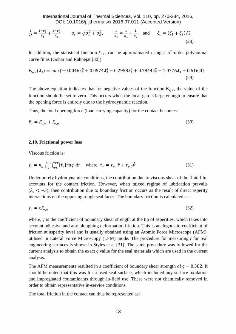
computational elements of various types, including quadrilateral, tetrahedral or a mixture of both. A typical computational mesh used in the current analysis is shown in Figure 3. A total number of 171,311 elements were used. A mixed mesh tetrahedral and quadrilateral elements were employed for both fluid and solid computational domains.
Figure 3: Computational domain with the unstructured mesh elements
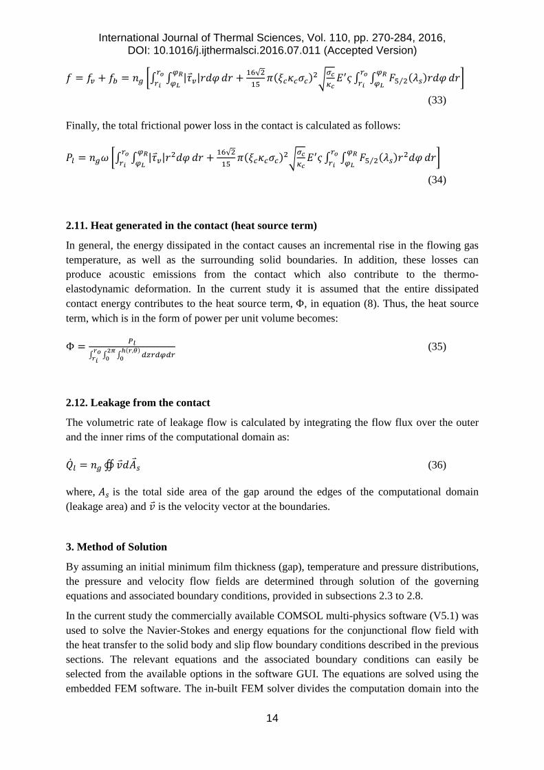
The quality of meshes and the mesh-dependency of the results to the type, size and distribution of the meshes were all examined. Table 1 lists the variations in the calculated opening force as the number of computational mesh elements increase. The computational time for each case is also listed in this table.
Table 1: Dependency of the results on mesh density and associated computational time
Number of mesh elements
Opening force (N)
Computational time (s)
58445 39631 248 92508 39803 431 156252 39887 797 171311 39935 920 201244 39939 4813
Quasi-static load balance is sought between the applied load (closing force) and the load carrying capacity of the contact (opening force). This is necessary in order to obtain the minimum contact film thickness (gap). The load balance is:
International Journal of Thermal Sciences, Vol. 110, pp. 270-284, 2016, DOI: 10.1016/j.ijthermalsci.2016.07.011 (Accepted Version)
16
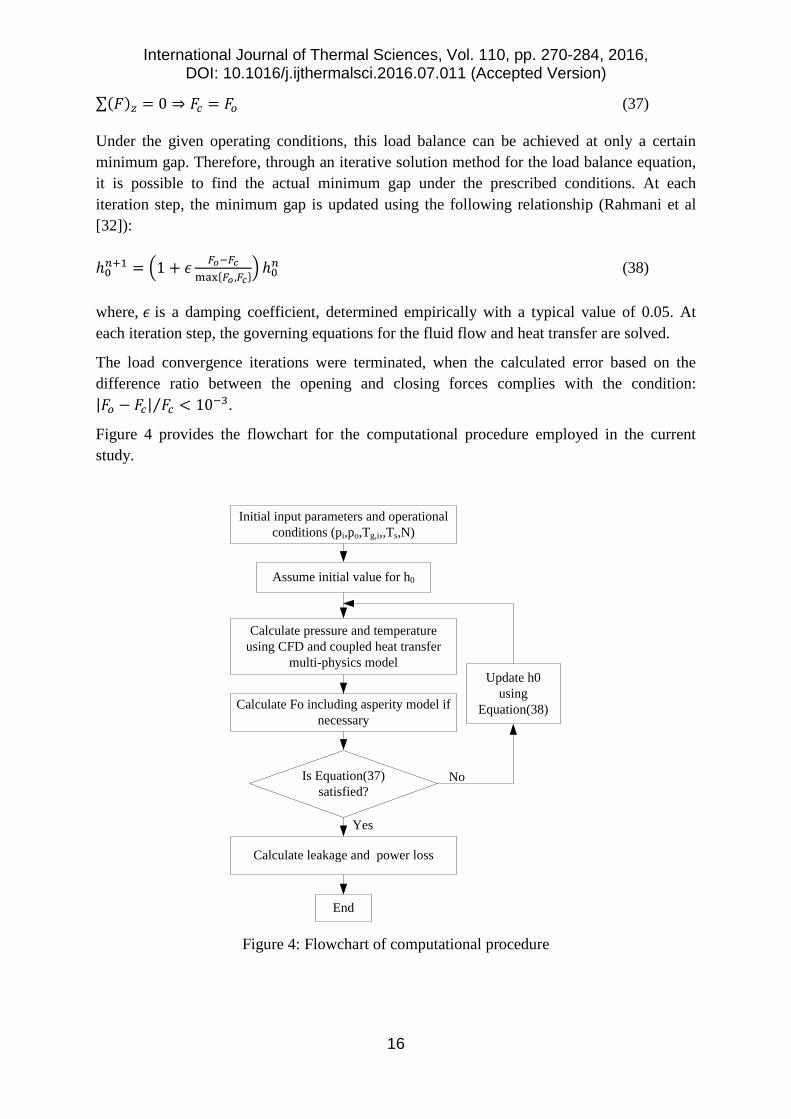
∑(𝐹𝐹)𝑧𝑧 = 0 ⇒ 𝐹𝐹𝑐𝑐 = 𝐹𝐹𝑜𝑜 (37)
Under the given operating conditions, this load balance can be achieved at only a certain minimum gap. Therefore, through an iterative solution method for the load balance equation, it is possible to find the actual minimum gap under the prescribed conditions. At each iteration step, the minimum gap is updated using the following relationship (Rahmani et al [32]):
ℎ0𝑖𝑖+1 = �1 + 𝜖𝜖 𝐹𝐹𝑜𝑜−𝐹𝐹𝑐𝑐max{𝐹𝐹𝑜𝑜 ,𝐹𝐹𝑐𝑐}� ℎ0
𝑖𝑖 (38)
where, 𝜖𝜖 is a damping coefficient, determined empirically with a typical value of 0.05. At each iteration step, the governing equations for the fluid flow and heat transfer are solved.
The load convergence iterations were terminated, when the calculated error based on the difference ratio between the opening and closing forces complies with the condition: |𝐹𝐹𝑜𝑜 − 𝐹𝐹𝑐𝑐| 𝐹𝐹𝑐𝑐⁄ < 10−3.
Figure 4 provides the flowchart for the computational procedure employed in the current study.
Initial input parameters and operational conditions (pi,po,Tg,i,,Ts,N)
Assume initial value for h0
Is Equation(37) satisfied?
Calculate leakage and power loss
Yes
Calculate pressure and temperature using CFD and coupled heat transfer
multi-physics model
Calculate Fo including asperity model if necessary
No
Update h0 using
Equation(38)
End
Figure 4: Flowchart of computational procedure
International Journal of Thermal Sciences, Vol. 110, pp. 270-284, 2016, DOI: 10.1016/j.ijthermalsci.2016.07.011 (Accepted Version)
17
4. System Specifications
4.1. Geometrical data
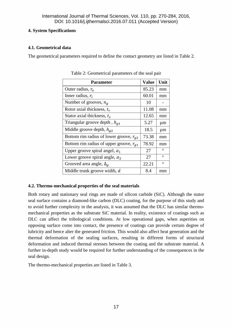
The geometrical parameters required to define the contact geometry are listed in Table 2.
Table 2: Geometrical parameters of the seal pair
Parameter Value Unit Outer radius, 𝑟𝑟𝑜𝑜 85.23 mm Inner radius, 𝑟𝑟𝑖𝑖 60.01 mm Number of grooves, 𝑛𝑛𝑔𝑔 10 - Rotor axial thickness, 𝑡𝑡𝑟𝑟 11.08 mm Stator axial thickness, 𝑡𝑡𝑠𝑠 12.65 mm Triangular groove depth , ℎ𝑔𝑔1 5.27 µm Middle groove depth, ℎ𝑔𝑔2 18.5 µm Bottom rim radius of lower groove, 𝑟𝑟𝑔𝑔2 73.38 mm Bottom rim radius of upper groove, 𝑟𝑟𝑔𝑔1 78.92 mm Upper groove spiral angel, 𝛼𝛼1 27 ° Lower groove spiral angle, 𝛼𝛼2 27 ° Grooved area angle, ∆𝑔𝑔 22.21 ° Middle trunk groove width, 𝑑𝑑 8.4 mm
4.2. Thermo-mechanical properties of the seal materials
Both rotary and stationary seal rings are made of silicon carbide (SiC). Although the stator seal surface contains a diamond-like carbon (DLC) coating, for the purpose of this study and to avoid further complexity in the analysis, it was assumed that the DLC has similar thermo-mechanical properties as the substrate SiC material. In reality, existence of coatings such as DLC can affect the tribological conditions. At low operational gaps, when asperities on opposing surface come into contact, the presence of coatings can provide certain degree of lubricity and hence alter the generated friction. This would also affect heat generation and the thermal deformation of the sealing surfaces, resulting in different forms of structural deformation and induced thermal stresses between the coating and the substrate material. A further in-depth study would be required for further understanding of the consequences in the seal design.
The thermo-mechanical properties are listed in Table 3.
International Journal of Thermal Sciences, Vol. 110, pp. 270-284, 2016, DOI: 10.1016/j.ijthermalsci.2016.07.011 (Accepted Version)
18
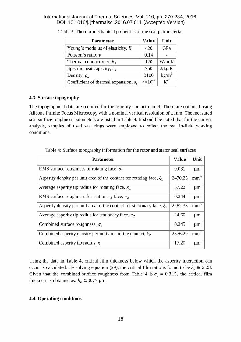
Table 3: Thermo-mechanical properties of the seal pair material
Parameter Value Unit Young’s modulus of elasticity, 𝐸𝐸 420 GPa Poisson’s ratio, 𝜈𝜈 0.14 - Thermal conductivity, 𝑘𝑘𝑠𝑠 120 W/m.K Specific heat capacity, 𝑐𝑐𝑠𝑠 750 J/kg.K Density, 𝜌𝜌𝑠𝑠 3100 kg/m3 Coefficient of thermal expansion, 𝜀𝜀𝑠𝑠 4×10⁻⁶ K-1
4.3. Surface topography
The topographical data are required for the asperity contact model. These are obtained using Alicona Infinite Focus Microscopy with a nominal vertical resolution of ±1nm. The measured seal surface roughness parameters are listed in Table 4. It should be noted that for the current analysis, samples of used seal rings were employed to reflect the real in-field working conditions.
Table 4: Surface topography information for the rotor and stator seal surfaces
Parameter Value Unit
RMS surface roughness of rotating face, 𝜎𝜎1 0.031 µm
Asperity density per unit area of the contact for rotating face, 𝜉𝜉1 2470.25 mm-2
Average asperity tip radius for rotating face, 𝜅𝜅1 57.22 µm
RMS surface roughness for stationary face, 𝜎𝜎2 0.344 µm
Asperity density per unit area of the contact for stationary face, 𝜉𝜉2 2282.33 mm-2
Average asperity tip radius for stationary face, 𝜅𝜅2 24.60 µm
Combined surface roughness, 𝜎𝜎𝑐𝑐 0.345 µm
Combined asperity density per unit area of the contact, 𝜉𝜉𝑐𝑐 2376.29 mm-2
Combined asperity tip radius, 𝜅𝜅𝑐𝑐 17.20 µm
Using the data in Table 4, critical film thickness below which the asperity interaction can occur is calculated. By solving equation (29), the critical film ratio is found to be 𝜆𝜆𝑠𝑠 ≅ 2.23. Given that the combined surface roughness from Table 4 is 𝜎𝜎𝑐𝑐 = 0.345, the critical film thickness is obtained as: ℎ𝑐𝑐 ≅ 0.77 µm.
4.4. Operating conditions
International Journal of Thermal Sciences, Vol. 110, pp. 270-284, 2016, DOI: 10.1016/j.ijthermalsci.2016.07.011 (Accepted Version)
19
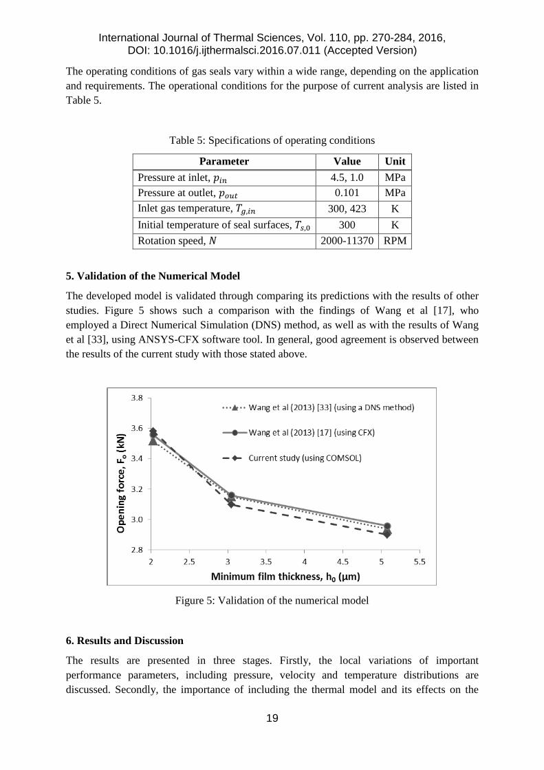
The operating conditions of gas seals vary within a wide range, depending on the application and requirements. The operational conditions for the purpose of current analysis are listed in Table 5.
Table 5: Specifications of operating conditions
Parameter Value Unit Pressure at inlet, 𝑝𝑝𝑖𝑖𝑖𝑖 4.5, 1.0 MPa Pressure at outlet, 𝑝𝑝𝑜𝑜𝑜𝑜𝑡𝑡 0.101 MPa Inlet gas temperature, 𝑇𝑇𝑔𝑔,𝑖𝑖𝑖𝑖 300, 423 K Initial temperature of seal surfaces, 𝑇𝑇𝑠𝑠,0 300 K Rotation speed, 𝑁𝑁 2000-11370 RPM
5. Validation of the Numerical Model
The developed model is validated through comparing its predictions with the results of other studies. Figure 5 shows such a comparison with the findings of Wang et al [17], who employed a Direct Numerical Simulation (DNS) method, as well as with the results of Wang et al [33], using ANSYS-CFX software tool. In general, good agreement is observed between the results of the current study with those stated above.
Figure 5: Validation of the numerical model
6. Results and Discussion
The results are presented in three stages. Firstly, the local variations of important performance parameters, including pressure, velocity and temperature distributions are discussed. Secondly, the importance of including the thermal model and its effects on the
International Journal of Thermal Sciences, Vol. 110, pp. 270-284, 2016, DOI: 10.1016/j.ijthermalsci.2016.07.011 (Accepted Version)
20
performance parameters is highlighted. This comparison is made for predicted results with thermal and isothermal models. Thirdly, the effect of asperity interactions with the incidence of thin films, leading to a mixed regime of lubrication is investigated.
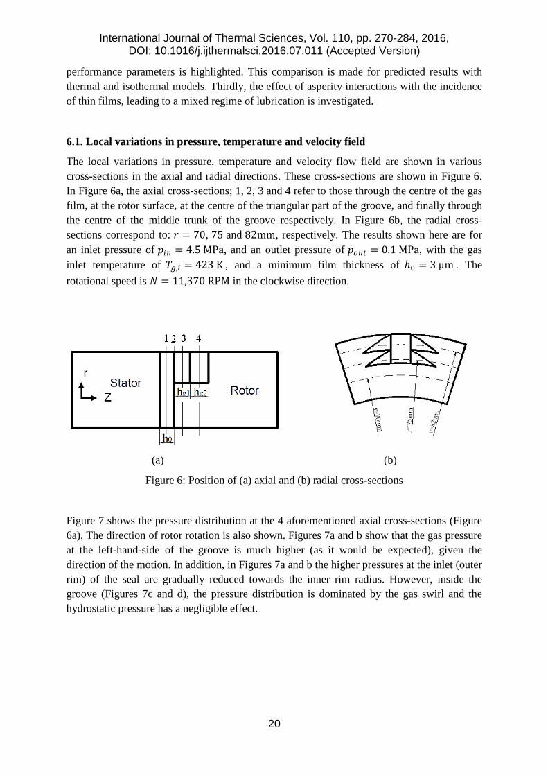
6.1. Local variations in pressure, temperature and velocity field
The local variations in pressure, temperature and velocity flow field are shown in various cross-sections in the axial and radial directions. These cross-sections are shown in Figure 6. In Figure 6a, the axial cross-sections; 1, 2, 3 and 4 refer to those through the centre of the gas film, at the rotor surface, at the centre of the triangular part of the groove, and finally through the centre of the middle trunk of the groove respectively. In Figure 6b, the radial cross-sections correspond to: 𝑟𝑟 = 70, 75 and 82mm, respectively. The results shown here are for an inlet pressure of 𝑝𝑝𝑖𝑖𝑖𝑖 = 4.5 MPa, and an outlet pressure of 𝑝𝑝𝑜𝑜𝑜𝑜𝑡𝑡 = 0.1 MPa, with the gas inlet temperature of 𝑇𝑇𝑔𝑔,𝑖𝑖 = 423 K , and a minimum film thickness of ℎ0 = 3 µm . The rotational speed is 𝑁𝑁 = 11,370 RPM in the clockwise direction.
(a) (b)
Figure 6: Position of (a) axial and (b) radial cross-sections
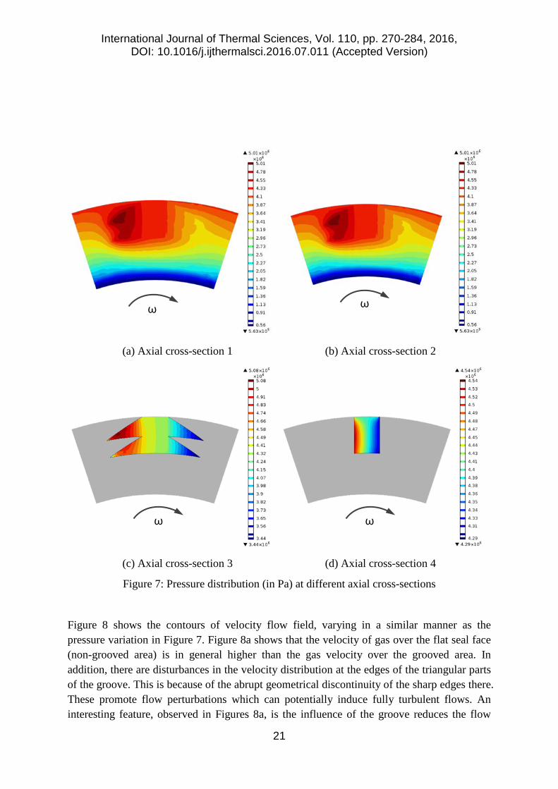
Figure 7 shows the pressure distribution at the 4 aforementioned axial cross-sections (Figure 6a). The direction of rotor rotation is also shown. Figures 7a and b show that the gas pressure at the left-hand-side of the groove is much higher (as it would be expected), given the direction of the motion. In addition, in Figures 7a and b the higher pressures at the inlet (outer rim) of the seal are gradually reduced towards the inner rim radius. However, inside the groove (Figures 7c and d), the pressure distribution is dominated by the gas swirl and the hydrostatic pressure has a negligible effect.
International Journal of Thermal Sciences, Vol. 110, pp. 270-284, 2016, DOI: 10.1016/j.ijthermalsci.2016.07.011 (Accepted Version)
21
(a) Axial cross-section 1 (b) Axial cross-section 2
(c) Axial cross-section 3 (d) Axial cross-section 4
Figure 7: Pressure distribution (in Pa) at different axial cross-sections
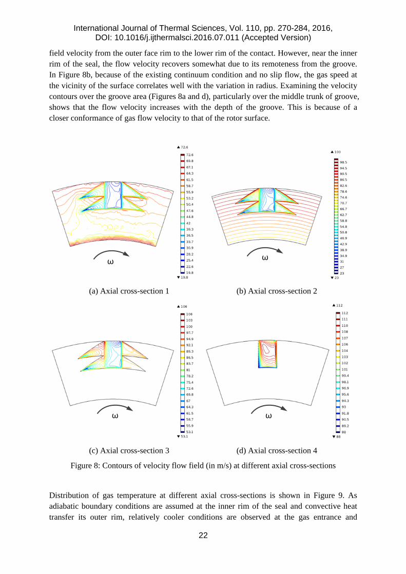
Figure 8 shows the contours of velocity flow field, varying in a similar manner as the pressure variation in Figure 7. Figure 8a shows that the velocity of gas over the flat seal face (non-grooved area) is in general higher than the gas velocity over the grooved area. In addition, there are disturbances in the velocity distribution at the edges of the triangular parts of the groove. This is because of the abrupt geometrical discontinuity of the sharp edges there. These promote flow perturbations which can potentially induce fully turbulent flows. An interesting feature, observed in Figures 8a, is the influence of the groove reduces the flow
ω ω
ω ω
International Journal of Thermal Sciences, Vol. 110, pp. 270-284, 2016, DOI: 10.1016/j.ijthermalsci.2016.07.011 (Accepted Version)
22
field velocity from the outer face rim to the lower rim of the contact. However, near the inner rim of the seal, the flow velocity recovers somewhat due to its remoteness from the groove. In Figure 8b, because of the existing continuum condition and no slip flow, the gas speed at the vicinity of the surface correlates well with the variation in radius. Examining the velocity contours over the groove area (Figures 8a and d), particularly over the middle trunk of groove, shows that the flow velocity increases with the depth of the groove. This is because of a closer conformance of gas flow velocity to that of the rotor surface.
(a) Axial cross-section 1 (b) Axial cross-section 2
(c) Axial cross-section 3 (d) Axial cross-section 4
Figure 8: Contours of velocity flow field (in m/s) at different axial cross-sections
Distribution of gas temperature at different axial cross-sections is shown in Figure 9. As adiabatic boundary conditions are assumed at the inner rim of the seal and convective heat transfer its outer rim, relatively cooler conditions are observed at the gas entrance and
ω ω
ω ω
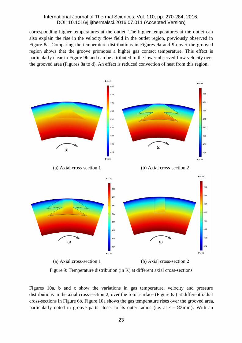
International Journal of Thermal Sciences, Vol. 110, pp. 270-284, 2016, DOI: 10.1016/j.ijthermalsci.2016.07.011 (Accepted Version)
23
corresponding higher temperatures at the outlet. The higher temperatures at the outlet can also explain the rise in the velocity flow field in the outlet region, previously observed in Figure 8a. Comparing the temperature distributions in Figures 9a and 9b over the grooved region shows that the groove promotes a higher gas contact temperature. This effect is particularly clear in Figure 9b and can be attributed to the lower observed flow velocity over the grooved area (Figures 8a to d). An effect is reduced convection of heat from this region.
(a) Axial cross-section 1 (b) Axial cross-section 2
(a) Axial cross-section 1 (b) Axial cross-section 2
Figure 9: Temperature distribution (in K) at different axial cross-sections
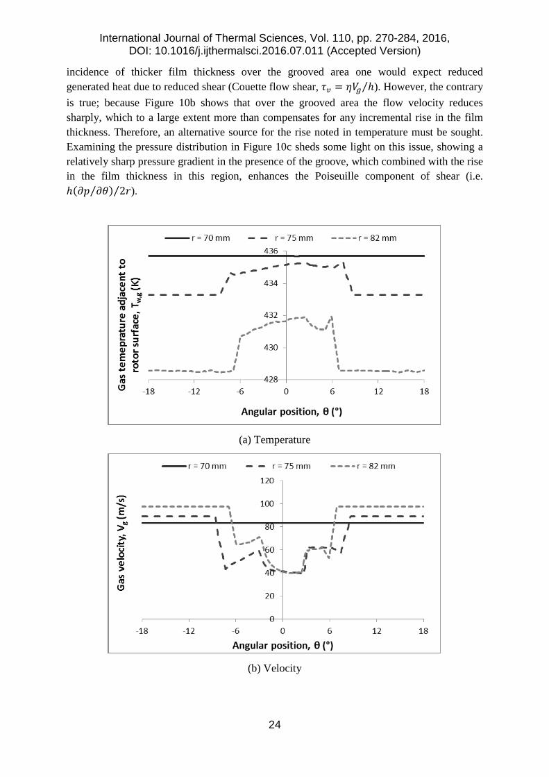
Figures 10a, b and c show the variations in gas temperature, velocity and pressure distributions in the axial cross-section 2, over the rotor surface (Figure 6a) at different radial cross-sections in Figure 6b. Figure 10a shows the gas temperature rises over the grooved area, particularly noted in groove parts closer to its outer radius (i.e. at 𝑟𝑟 = 82mm). With an
ω ω
ω ω
International Journal of Thermal Sciences, Vol. 110, pp. 270-284, 2016, DOI: 10.1016/j.ijthermalsci.2016.07.011 (Accepted Version)
24
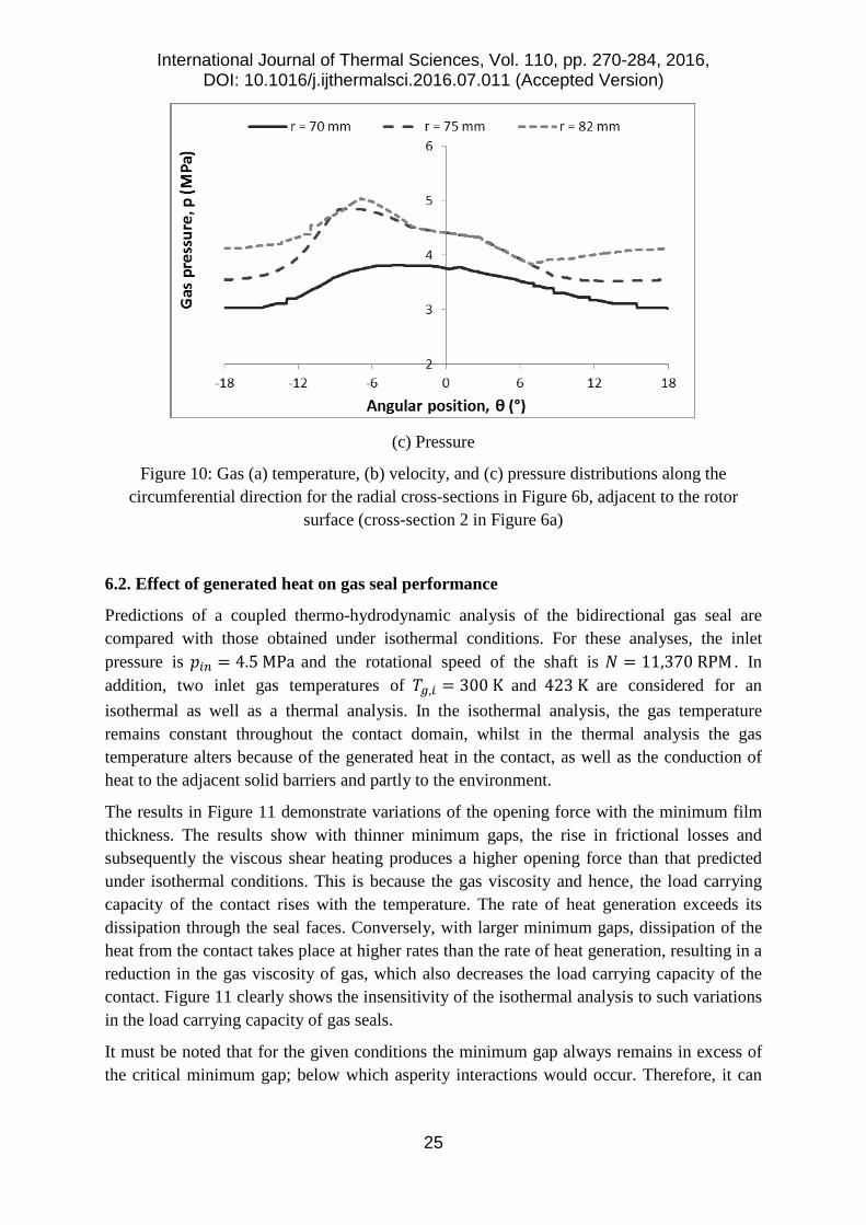
incidence of thicker film thickness over the grooved area one would expect reduced generated heat due to reduced shear (Couette flow shear, 𝜏𝜏𝑣𝑣 = 𝜂𝜂𝑉𝑉𝑔𝑔 ℎ⁄ ). However, the contrary is true; because Figure 10b shows that over the grooved area the flow velocity reduces sharply, which to a large extent more than compensates for any incremental rise in the film thickness. Therefore, an alternative source for the rise noted in temperature must be sought. Examining the pressure distribution in Figure 10c sheds some light on this issue, showing a relatively sharp pressure gradient in the presence of the groove, which combined with the rise in the film thickness in this region, enhances the Poiseuille component of shear (i.e. ℎ(𝜕𝜕𝑝𝑝 𝜕𝜕𝜃𝜃⁄ ) 2𝑟𝑟⁄ ).
(a) Temperature
(b) Velocity
International Journal of Thermal Sciences, Vol. 110, pp. 270-284, 2016, DOI: 10.1016/j.ijthermalsci.2016.07.011 (Accepted Version)
25
(c) Pressure
Figure 10: Gas (a) temperature, (b) velocity, and (c) pressure distributions along the circumferential direction for the radial cross-sections in Figure 6b, adjacent to the rotor
surface (cross-section 2 in Figure 6a)
6.2. Effect of generated heat on gas seal performance
Predictions of a coupled thermo-hydrodynamic analysis of the bidirectional gas seal are compared with those obtained under isothermal conditions. For these analyses, the inlet pressure is 𝑝𝑝𝑖𝑖𝑖𝑖 = 4.5 MPa and the rotational speed of the shaft is 𝑁𝑁 = 11,370 RPM . In addition, two inlet gas temperatures of 𝑇𝑇𝑔𝑔,𝑖𝑖 = 300 K and 423 K are considered for an isothermal as well as a thermal analysis. In the isothermal analysis, the gas temperature remains constant throughout the contact domain, whilst in the thermal analysis the gas temperature alters because of the generated heat in the contact, as well as the conduction of heat to the adjacent solid barriers and partly to the environment.
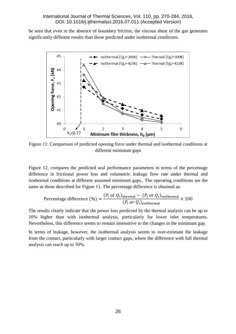
The results in Figure 11 demonstrate variations of the opening force with the minimum film thickness. The results show with thinner minimum gaps, the rise in frictional losses and subsequently the viscous shear heating produces a higher opening force than that predicted under isothermal conditions. This is because the gas viscosity and hence, the load carrying capacity of the contact rises with the temperature. The rate of heat generation exceeds its dissipation through the seal faces. Conversely, with larger minimum gaps, dissipation of the heat from the contact takes place at higher rates than the rate of heat generation, resulting in a reduction in the gas viscosity of gas, which also decreases the load carrying capacity of the contact. Figure 11 clearly shows the insensitivity of the isothermal analysis to such variations in the load carrying capacity of gas seals.
It must be noted that for the given conditions the minimum gap always remains in excess of the critical minimum gap; below which asperity interactions would occur. Therefore, it can
International Journal of Thermal Sciences, Vol. 110, pp. 270-284, 2016, DOI: 10.1016/j.ijthermalsci.2016.07.011 (Accepted Version)
26
be seen that even in the absence of boundary friction, the viscous shear of the gas generates significantly different results than those predicted under isothermal conditions.
Figure 11: Comparison of predicted opening force under thermal and isothermal conditions at
different minimum gaps
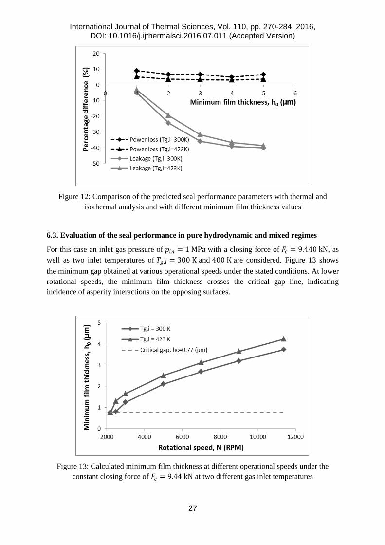
Figure 12, compares the predicted seal performance parameters in terms of the percentage difference in frictional power loss and volumetric leakage flow rate under thermal and isothermal conditions at different assumed minimum gaps.. The operating conditions are the same as those described for Figure 11. The percentage difference is obtained as:
Percentage difference (%) =(𝑃𝑃𝑙𝑙 or 𝑄𝑄𝑙𝑙)thermal − (𝑃𝑃𝑙𝑙 or 𝑄𝑄𝑙𝑙)isothermal
(𝑃𝑃𝑙𝑙 𝑜𝑜𝑟𝑟 𝑄𝑄𝑙𝑙)isothermal× 100
The results clearly indicate that the power loss predicted by the thermal analysis can be up to 10% higher than with isothermal analysis, particularly for lower inlet temperatures. Nevertheless, this difference seems to remain insensitive to the changes in the minimum gap.
In terms of leakage, however, the isothermal analysis seems to over-estimate the leakage from the contact, particularly with larger contact gaps, where the difference with full thermal analysis can reach up to 50%.
International Journal of Thermal Sciences, Vol. 110, pp. 270-284, 2016, DOI: 10.1016/j.ijthermalsci.2016.07.011 (Accepted Version)
27
Figure 12: Comparison of the predicted seal performance parameters with thermal and
isothermal analysis and with different minimum film thickness values
6.3. Evaluation of the seal performance in pure hydrodynamic and mixed regimes
For this case an inlet gas pressure of 𝑝𝑝𝑖𝑖𝑖𝑖 = 1 MPa with a closing force of 𝐹𝐹𝑐𝑐 = 9.440 kN, as well as two inlet temperatures of 𝑇𝑇𝑔𝑔,𝑖𝑖 = 300 K and 400 K are considered. Figure 13 shows the minimum gap obtained at various operational speeds under the stated conditions. At lower rotational speeds, the minimum film thickness crosses the critical gap line, indicating incidence of asperity interactions on the opposing surfaces.
Figure 13: Calculated minimum film thickness at different operational speeds under the
constant closing force of 𝐹𝐹𝑐𝑐 = 9.44 kN at two different gas inlet temperatures
International Journal of Thermal Sciences, Vol. 110, pp. 270-284, 2016, DOI: 10.1016/j.ijthermalsci.2016.07.011 (Accepted Version)
28
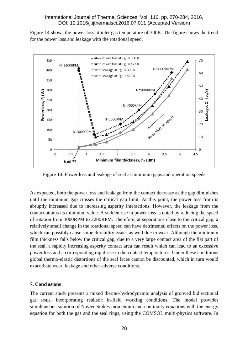
Figure 14 shows the power loss at inlet gas temperature of 300K. The figure shows the trend for the power loss and leakage with the rotational speed.
Figure 14: Power loss and leakage of seal at minimum gaps and operation speeds
As expected, both the power loss and leakage from the contact decrease as the gap diminishes until the minimum gap crosses the critical gap limit. At this point, the power loss from is abruptly increased due to increasing asperity interactions. However, the leakage from the contact attains its minimum value. A sudden rise in power loss is noted by reducing the speed of rotation from 3000RPM to 2200RPM. Therefore, at separations close to the critical gap, a relatively small change in the rotational speed can have detrimental effects on the power loss, which can possibly cause some durability issues as well due to wear. Although the minimum film thickness falls below the critical gap, due to a very large contact area of the flat part of the seal, a rapidly increasing asperity contact area can result which can lead to an excessive power loss and a corresponding rapid rise in the contact temperatures. Under these conditions global thermo-elastic distortions of the seal faces cannot be discounted, which in turn would exacerbate wear, leakage and other adverse conditions.
7. Conclusions
The current study presents a mixed thermo-hydrodynamic analysis of grooved bidirectional gas seals, incorporating realistic in-field working conditions. The model provides simultaneous solution of Navier-Stokes momentum and continuity equations with the energy equation for both the gas and the seal rings, using the COMSOL multi-physics software. In
International Journal of Thermal Sciences, Vol. 110, pp. 270-284, 2016, DOI: 10.1016/j.ijthermalsci.2016.07.011 (Accepted Version)
29
addition, the slip flow boundary conditions are included, when required dependent on the operating conditions.
Measured topographical data using white light interferometry are used for the mixed regime of lubrication model. Additionally, AFM in lateral force mode is employed to determine the coefficient of friction at the tip of the asperities; specific to the surfaces of the seal faces.
The results from the thermal model are compared with those from an isothermal analysis, indicating that prediction of the latter lead to some unrealistic outcomes with over or under-estimation of key performance parameters.
The local variation of pressure, temperature and velocity flow field provides further in-depth knowledge of the underlying mechanisms of gas seal operation, which cannot be obtained using conventional 1D or 2D usual predictive methods.
It is shown that direct asperity contacts, in separations lower than the critical gap between the seal faces can lead to significant power loss. The sudden rise in generated heat in the contact at relatively low speeds can potentially cause durability issues.
The groove geometry produces local pressure perturbations which affect the seal performance. Further investigation of this phenomenon is necessary. It may be possible to determine an appropriate groove design, which would promotes turbulent flow; increasing the load carrying capacity and aid heat removal from the contact, thus guarding against undesired excessive thermo-elastic distortions. In addition, the contact stiffness and effect of dynamic axial vibrations should be studied for enhanced thermo-hydrodynamic performance of gas seals.
Acknowledgment
The first author wishes to express her gratitude for funding by the Chinese Scholarship Council (CSC), providing the opportunity to carry out this research at Loughborough University, UK.
The authors are grateful for the information supplied by John Crane Ltd.
References
[1] Kowalski, C.A. and Basu, P., 1995, Reverse rotation capability of spiral-groove gas face seals, Tribology Transactions, Vol. 38, pp.549-556
[2] Basu, P., 1992, Analysis of radial groove gas face seal, Tribology Transactions, Vol.35, pp. 11-20
[3] Takeuchi, T., Kataoka, T., Nagasaka, H., Kakutani, M., Ito, M. and Muraki, R., 1998, Advanced dry gas seal by the dynamic ion beam mixing technique, Proceedings of the 27th Turbomachinery symposium, pp. 39-48
[4] Wang, Y., 2004, Bi-direction rotatable face seal with spiral grooves, US Patent Publication No. 6726213 B2
International Journal of Thermal Sciences, Vol. 110, pp. 270-284, 2016, DOI: 10.1016/j.ijthermalsci.2016.07.011 (Accepted Version)
30
[5] Goldswain, I.M. and Do Boer Hignett, M.W., 1993, Mechanical face seal with trapezoidal shaped grooves on a sealing face, US Patent 5222743 A
[6] Bonneau, D., Huitric, J. and Tournerie, B., 1993, Finite element analysis of grooved gas thrust bearings and grooved gas face seals, Journal of Tribology, Transactions of the ASME, Vol. 115, pp. 348-354
[7] Zirkelback, N., 2000, Parametric study of spiral groove gas face seals, Tribology Transactions, Vol. 43, pp. 337-343
[8] Xu, J., Peng, X., Bai, S., Meng, X., 2012, CFD simulation of microscale flow field in spiral groove dry gas seal, Proceedings of IEEE/ASME International Conference on Mechatronics and Embedded Systems and Applications (MESA), pp. 211-217, DOI: 10.1109/MESA.2012.6275564
[9] Shahin, I., Gadala, M., Alqaradawi, M. and Badr, O., 2013, Three dimensional computation study for spiral dry gas seal with constant groove depth and different tapered grooves, Procedia Engineering, Vol. 68, pp. 205-212
[10] Wang, B., Zhang, H. and, Cao, H., 2013, Flow dynamics of a spiral-groove dry-gas seal, Chinese Journal of Mechanical Engineering, Vol. 26, No. 1, pp. 78-84
[11] Su, H., Rahmani, R. and Rahnejat, H., 2016, Performance evaluation of bidirectional dry gas seals with special groove geometry, Tribology Transactions, DOI: 10.1080/10402004.2016.1146380
[12] Ruan B., Salant R. and Green I., 1997, A mixed model of liquid/gas mechanical face seal, Tribology Transactions, Vol. 40, pp. 647-657
[13] Ruan, B., 2000, Finite element analysis of the spiral groove gas face seal at the slow speed and the low pressure conditions-slip flow considerations, Tribology Transactions, Vol. 43, No. 3, pp. 411-418
[14] Brunetire, N. and Modolo, B., 2009, Heat transfer in a mechanical face seal, International Journal of Thermal Sciences, Vol. 48, pp.781-794
[15] Wang, B. and Zhang, H., 2011, Numerical analysis of a spiral-groove dry-gas seal considering micro-scale effects, Chinese Journal of Mechanical Engineering, Vol. 24, pp. 1-8
[16] Thomas, S., Brunetiere, N. and Tournerie, B., 2007, Numerical modelling of high pressure gas face seals, Journal of Tribology, Transactions of the ASME, Vol. 129, pp. 841-850
[17] Wang, H., Zhu, B., Lin, J. and Ye, C., 2013, A thermohydrodynamic analysis of dry gas seals for high-temperature gas-cooled reactor, Journal of Tribology, Transactions of the ASME, Vol. 135, pp. 021701-1 to 9
[18] Szeri, A.Z., Fluid film lubrication: theory and design, Cambridge University Press, US, 1998
[19] Munson, B.R., Young, D.F. and Okiishi, T.H., 2006, Fundamentals of fluid mechanics, 5th Ed., John Wiley & Sons, Inc. pp.272-334
International Journal of Thermal Sciences, Vol. 110, pp. 270-284, 2016, DOI: 10.1016/j.ijthermalsci.2016.07.011 (Accepted Version)
31
[20] In-built functions available in COMSOL multi-physics software library
[21] Fukui, S. and Kaneko, R., 1988, Analysis of ultra-thin gas film lubrication based on linearized Boltzmann equation: First report – Derivation of a generalized lubrication equation including thermal creep flow, Journal of Tribology, Transactions of the ASME, Vol. 110, pp. 253-261
[22] COMSOL v.5.1 Help Documents: Microfluidics Module User’s Guide, p. 204
[23] Gad-el-Hak, M., 1999, The fluid mechanics of microdevices – The Freeman Scholar Lecture, Journal of Fluids Engineering, Transactions of the ASME, Vol. 121, pp. 5-33
[24] Karniadakis, G., Beskok, A. and Aluru, N., Microflows and Nanoflows, Springer, 2005, pp. 63-67
[25] Shellef, R.A. and Johnson, R.P., 1992, A bi-directional gas face seal, Tribology Transactions, Vol. 35, No. 1, pp. 53-58
[26] Zhao, Y., Yuan, S., Hu, J. and Wei, C., 2015, Nonlinear dynamic analysis of rotary seal ring considering creep rotation, Tribology International, Vol. 82, pp. 101-109
[27] Noda, N., Hetnarski, R.B. and Tanigawa, Y., Thermal Stresses, 2nd Ed., CRC Press, New York, 2002, pp. 81-90
[28] Incropera, F.P., Dewitt, D.P., Bergman, T.L. and Lavine, S., Introduction to heat transfer, 5th Ed., John Wiley & Sons, pp. 383-433
[29] Greenwood J.A. and Tripp, J.H., 1970-71, The contact of two nominally flat rough surfaces, Proceedings of Institution of Mechanical Engineers, Vol. 185, pp. 625-633
[30] Gohar, R. and Rahnejat, H., Fundamentals of Tribology, Imperial College Press, 2008, London.
[31] Styles, G., Rahmani, R., Rahnejat, H. and Fitzsimons, B., 2014, In-cycle and life-time friction transience in piston ring–liner conjunction under mixed regime of lubrication, International Journal of Engine Research, Vol. 15, No. 7, pp. 862-876
[32] Rahmani, R., Theodossiades, S., Rahnejat, H. and & Fitzsimons, B., 2012, Transient elastohydrodynamic lubrication of rough new or worn piston compression ring conjunction with an out-of-round cylinder bore. Proceedings of the Institution of Mechanical Engineers, Part J: Journal of Engineering Tribology, Vol. 226, No. 4, pp. 284-305
[33] Wang, B., Zhang, H. and, Cao, H., 2013, Flow dynamics of a spiral-groove dry-gas seal, Chinese Journal of Mechanical Engineering, Vol. 26, No. 1, pp. 78-84