Embed Size (px)
Citation preview
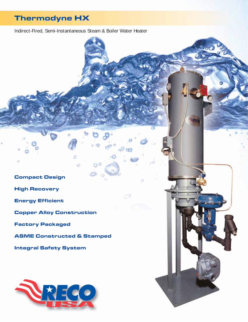
Thermodyne HX
Indirect-Fired, Semi-Instantaneous Steam & Boiler Water Heater
Compact Design
High Recovery
Energy Efficient
Copper Alloy Construction
Factory Packaged
ASME Constructed & Stamped
Integral Safety System
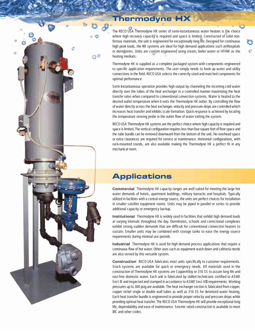
ApplicationsCommercial Thermodyne HX capacity ranges are well suited for meeting the large hotwater demands of hotels, apartment buildings, military barracks and hospitals. Typicallyutilized in facilities with a central energy source, the units are perfect choices for installationin smaller satellite equipment rooms. Units may be piped in parallel or series to provideadditional capacity or emergency backup.
Institutional Thermodyne HX is widely used in facilities that exhibit high demand loadsat varying intervals throughout the day. Dormitories, schools and correctional complexesexhibit strong sudden demands that are difficult for conventional convection heaters tosustain. Smaller units may be combined with storage tanks to ease the energy sourcerequirements during minimal use periods.
Industrial Thermodyne HX is used for high demand process applications that require acontinuous flow of hot water. Other uses such as equipment wash down and cafeteria needsare also served by this versatile system.
Construction RECO USA fabricates most units specifically to customer requirements.Stock systems are available for quick or emergency needs. All materials used in theconstruction of Thermodyne HX systems are CopperAlloy or 316 SS to assure long life andrust-free domestic water. Each unit is fabricated by skilled technicians certified to ASMESect IX and inspected and stamped in accordance to ASME Sect VIII requirements. Workingpressures up to 300 psig are available. The heat exchanger section is fabricated from copper,copper nickel single or double wall tubes as well as 316 SS for deionized water heating.Each heat transfer bundle is engineered to provide proper velocity and pressure drops whileproviding optimal heat transfer. The RECO USA Thermodyne HX will provide exceptional longlife, dependability and ease of maintenance. Seismic rated construction is available to meetIBC and other codes.
The RECO USA Thermodyne HX series of semi-instantaneous water heaters is the choicewhere high recovery capacity is required and space is limited. Constructed of solid non-ferrous materials, the unit is engineered for exceptionally long life. Designed for continuoushigh peak loads, the HX systems are ideal for high demand applications such as hospitalsor dormitories. Units are custom engineered using steam, boiler water or HTHW as theheating medium.
Thermodyne HX is supplied as a complete packaged system with components engineeredto specific application requirements. The user simply needs to hook up water and utilityconnections in the field. RECO USA selects the correctly sized and matched components foroptimal performance.
Semi-Instantaneous operation provides high output by channeling the incoming cold waterdirectly over the tubes of the heat exchanger in a controlled manner maximizing the heattransfer rates when compared to conventional convection systems. Water is heated to thedesired outlet temperature when it exits the Thermodyne HX outlet. By controlling the flowof water directly across the heat exchanger, velocity and pressure drops are controlled whichincreases heat transfer and inhibits scale formation. Quick response is achieved by locatingthe temperature sensing probe in the outlet flow of water exiting the system.
RECO USA Thermodyne HX systems are the perfect choice where high capacity is required andspace is limited. The vertical configuration requires less than four square feet of floor space andthe tube bundle can he removed downward from the bottom of the unit. No overhead spaceor extra clearances are required for service or maintenance. Horizontal configurations, withrack-mounted stands, are also available making the Thermodyne HX a perfect fit in anymechanical room.
Thermodyne HX
Sizing
0
10
20
30
40
50
60
70
80
90
100
25 50 75 100 125 150 175 200 225 250 275 300 325 350 375 400
Fixture Units (Actual Numbers)
0
50
100
150
200
250
300
350
400
450
2 4 6 8 10 12 14 16 18 20 22 24 26 28 30
Fixture Units (x100)
Gallo
ns P
er M
inut
e
Office Buildingsand Schools
Restaurants Hospitals, Nursing Homes,Nurses Residences, Dormitories,Hotels and Motels
Apartment Houses
For greaterdetail, seeenlarged
chart to right
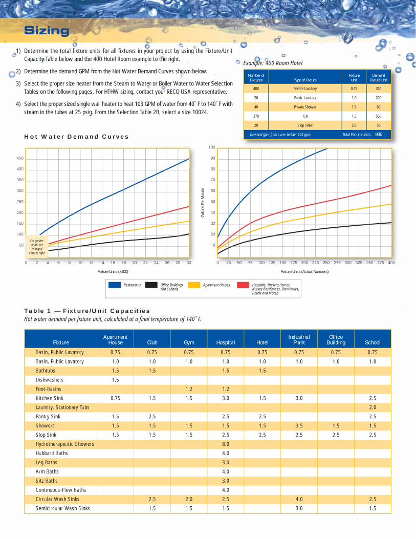
Table 1 — Fixture/Unit CapacitiesHot water demand per fixture unit, calculated at a final temperature of 140˚F.
SchoolOffice
BuildingIndustrial
PlantHotelHospitalGymClubApartment
HouseFixture
Basin, Public Lavatory
Basin, Public Lavatory
Bathtubs
Dishwashers
Foot-Basins
Kitchen Sink
Laundry, Stationary Tubs
Pantry Sink
Showers
Slop Sink
Hydrotherapeutic Showers
Hubbard Baths
Leg Baths
Arm Baths
Sitz Baths
Continuous-Flow Baths
Circular Wash Sinks
Semicircular Wash Sinks
0.750.750.750.750.750.750.750.75
1.0 1.0 1.0 1.0 1.0 1.0 1.0 1.0
1.5
1.5
1.2 1.2
0.75 1.5 1.5 3.0 1.5 3.0 2.5
2.0
2.52.52.52.51.5
1.51.53.51.51.51.51.51.5
2.52.52.52.52.5
8.0
4.0
3.0
4.0
3.0
4.0
1.51.51.5
2.5
1.5
2.0
1.5
2.5
1.5
4.0
3.0
2.5
1.5
1.5 1.5 1.5
1) Determine the total fixture units for all fixtures in your project by using the Fixture/UnitCapacity Table below and the 400 Hotel Room example to the right.
2) Determine the demand GPM from the Hot Water Demand Curves shown below.
3) Select the proper size heater from the Steam to Water or Boiler Water to Water SelectionTables on the following pages. For HTHW sizing, contact your RECO USA representative.
4) Select the proper sized single wall heater to heat 103 GPM of water from 40˚F to 140˚F withsteam in the tubes at 25 psig. From the Selection Table 2B, select a size 10024.
Number ofFixtures Type of Fixture
FixtureUnit
DemandFixture Unit
400 Private Lavatory 0.75 300
20 Public Lavatory 1.0 200
40 Private Shower 1.5 60
370 Tub 1.5 556
20 Slop Sinks 2.5 50
986Total Fixture Units:Demand gpm from curve below: 103 gpm
Example: 400 Room Hotel
Hot Water Demand Curves
Typical Boiler Water Control Piping
Compound Pressure Gauge
Trap Strainer
Main Trap Condensate Outlet
Drip Trap
Inlet Strainer
Steam Inlet
Element Head
CompoundPressure Gauge
Shut-off Cock
Condensate Outlet
Main F&T Trap
2-way Pilot Operatedcontrol Valve withSafety Solenoid
Temperature PilotValve Assembly
Steam Inlet Strainer
Steam Inlet
2-way Air-operatedControl Valve
HXV=Vertical
HXH=Horizontal
– – –
125 Psig or
150 Psig
Copper Nickel=C
Stainless Steel=S
Choose from Tables
2A - 5B to determine
Heating Coil Model
Single Wall=S
Double Wall=D
(Copper is standard)
Electric=EL
Pneumatic=PN
Self Contained=SC
Steam=S
Water=W
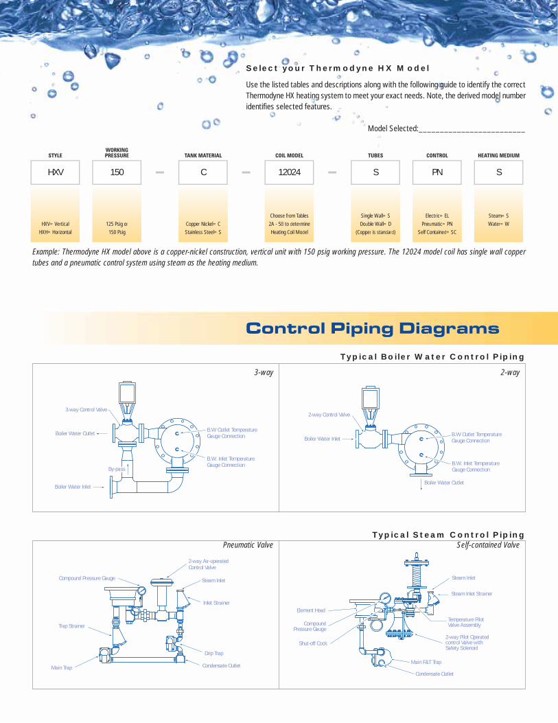
STYLEWORKINGPRESSURE TANK MATERIAL COIL MODEL TUBES CONTROL HEATING MEDIUM
HXV 150 C 12024 S PN S
Control Piping Diagrams
Select your Thermodyne HX Model
Use the listed tables and descriptions along with the following guide to identify the correctThermodyne HX heating system to meet your exact needs. Note, the derived model numberidentifies selected features.
Model Selected:_________________________
Example: Thermodyne HX model above is a copper-nickel construction, vertical unit with 150 psig working pressure. The 12024 model coil has single wall coppertubes and a pneumatic control system using steam as the heating medium.
3-way 2-way
Pneumatic Valve Self-contained Valve
2-way Control Valve
Boiler Water Inlet
Boiler Water Outlet
B.W. Inlet TemperatureGauge Connection
B.W Outlet TemperatureGauge Connection
Boiler Water Inlet
Boiler Water Outlet
B.W. Inlet TemperatureGauge Connection
B.W Outlet TemperatureGauge Connection
3-way Control Valve
By-passBy-passBy-pass
Typical Steam Control Piping
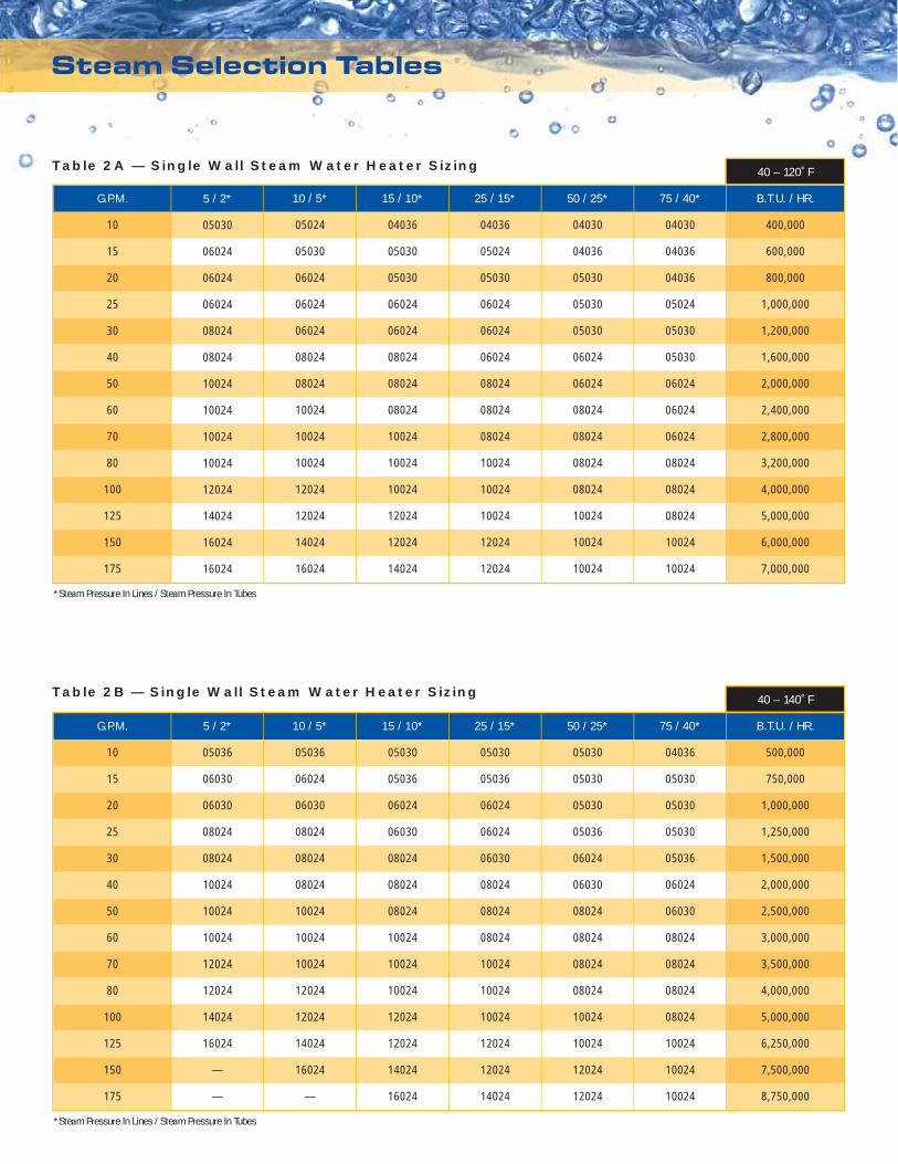
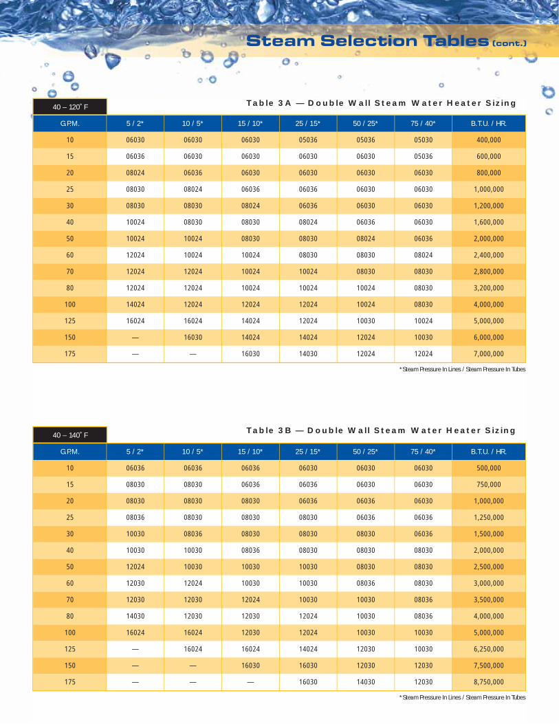
*Steam Pressure In Lines / Steam Pressure In Tubes
*Steam Pressure In Lines / Steam Pressure In Tubes
5 / 2*
05030
06024
06024
06024
08024
08024
10024
10024
10024
10024
12024
14024
16024
16024
10 / 5*
05024
05030
06024
06024
06024
08024
08024
10024
10024
10024
12024
12024
14024
16024
15 / 10*
04036
05030
05030
06024
06024
08024
08024
08024
10024
10024
10024
12024
12024
14024
25 / 15*
04036
05024
05030
06024
06024
06024
08024
08024
08024
10024
10024
10024
12024
12024
50 / 25*
04030
04036
05030
05030
05030
06024
06024
08024
08024
08024
08024
10024
10024
10024
75 / 40*
04030
04036
04036
05024
05030
05030
06024
06024
06024
08024
08024
08024
10024
10024
40 – 120˚F
G.P.M.
10
15
20
25
30
40
50
60
70
80
100
125
150
175
5 / 2*
05036
06030
06030
08024
08024
10024
10024
10024
12024
12024
14024
16024
—
—
10 / 5*
05036
06024
06030
08024
08024
08024
10024
10024
10024
12024
12024
14024
16024
—
15 / 10*
05030
05036
06024
06030
08024
08024
08024
10024
10024
10024
12024
12024
14024
16024
25 / 15*
05030
05036
06024
06024
06030
08024
08024
08024
10024
10024
10024
12024
12024
14024
50 / 25*
05030
05030
05030
05036
06024
06030
08024
08024
08024
08024
10024
10024
12024
12024
75 / 40*
04036
05030
05030
05030
05036
06024
06030
08024
08024
08024
08024
10024
10024
10024
40 – 140˚F
G.P.M.
10
15
20
25
30
40
50
60
70
80
100
125
150
175
B.T.U. / HR.
400,000
600,000
800,000
1,000,000
1,200,000
1,600,000
2,000,000
2,400,000
2,800,000
3,200,000
4,000,000
5,000,000
6,000,000
7,000,000
B.T.U. / HR.
500,000
750,000
1,000,000
1,250,000
1,500,000
2,000,000
2,500,000
3,000,000
3,500,000
4,000,000
5,000,000
6,250,000
7,500,000
8,750,000
Steam Selection Tables
Table 2A — Single Wall Steam Water Heater Sizing
Table 2B — Single Wall Steam Water Heater Sizing
Steam Selection Tables (cont.)
40 – 120˚F
*Steam Pressure In Lines / Steam Pressure In Tubes
5 / 2*
06030
06036
08024
08030
08030
10024
10024
12024
12024
12024
14024
16024
—
—
10 / 5*
06030
06030
06036
08024
08030
08030
10024
10024
12024
12024
12024
16024
16030
—
15 / 10*
06030
06030
06030
06036
08024
08030
08030
10024
10024
10024
12024
14024
14024
16030
25 / 15*
05036
06030
06030
06036
06036
08024
08030
08030
10024
10024
12024
12024
14024
14030
50 / 25*
05036
06030
06030
06030
06030
06036
08024
08030
08030
10024
10024
10030
12024
12024
75 / 40*
05030
05036
06030
06030
06030
06030
06036
08024
08030
08030
08030
10024
10030
12024
G.P.M.
10
15
20
25
30
40
50
60
70
80
100
125
150
175
B.T.U. / HR.
400,000
600,000
800,000
1,000,000
1,200,000
1,600,000
2,000,000
2,400,000
2,800,000
3,200,000
4,000,000
5,000,000
6,000,000
7,000,000
*Steam Pressure In Lines / Steam Pressure In Tubes
5 / 2*
06036
08030
08030
08036
10030
10030
12024
12030
12030
14030
16024
—
—
—
10 / 5*
06036
08030
08030
08030
08036
10030
10030
12024
12030
12030
16024
16024
—
—
15 / 10*
06036
06036
08030
08030
08030
08036
10030
10030
12024
12030
12030
16024
16030
—
25 / 15*
06030
06036
06036
08030
08030
08030
10030
10030
10030
12024
12024
14024
16030
16030
50 / 25*
06030
06030
06036
06036
08030
08030
08030
08036
10030
10030
10030
12030
12030
14030
75 / 40*
06030
06030
06030
06036
06036
08030
08030
08030
08036
08036
10030
10030
12030
12030
G.P.M.
10
15
20
25
30
40
50
60
70
80
100
125
150
175
B.T.U. / HR.
500,000
750,000
1,000,000
1,250,000
1,500,000
2,000,000
2,500,000
3,000,000
3,500,000
4,000,000
5,000,000
6,250,000
7,500,000
8,750,000
40 – 140˚F
Table 3A — Double Wall Steam Water Heater Sizing
Table 3B — Double Wall Steam Water Heater Sizing
Boiler Selection Tables
40 – 120˚F
G.P.M.
10
15
20
25
30
40
50
60
70
80
100
125
PASS
2
2
2
2
2
2
2
2
2
2
2
2
BW G.P.M.
41
61
82
102
123
164
205
246
287
327
409
512
MODEL
06036
06036
08030
08030
08030
10024
10024
12024
12024
12024
14024
16030
BOILER WATER 180 – 160˚F BOILER WATER 200 – 180˚F
PASS
2
2
2
2
2
2
2
2
2
2
2
2
BW G.P.M.
41
61
82
102
123
164
205
246
287
327
409
512
MODEL
06024
06030
08024
08024
08024
10024
10024
12024
12024
12024
14024
16030
B.T.U. / HR.
400,000
600,000
800,000
1,000,000
1,200,000
1,600,000
2,000,000
2,400,000
2,800,000
3,200,000
4,000,000
5,000,000
40 – 140˚F
G.P.M.
10
15
20
25
30
40
50
60
70
80
100
PASS
2
2
2
2
2
2
2
2
2
2
2
BW G.P.M.
51
76
102
128
153
204
255
306
357
409
511
MODEL
08030
08036
08036
10030
10030
10036
12030
12030
12030
14030
16030
BOILER WATER 180 – 160˚F BOILER WATER 200 – 180˚F
PASS
2
2
2
2
2
2
2
2
2
2
2
BW G.P.M.
51
76
102
128
153
204
255
306
357
409
511
MODEL
06030
08024
08030
08030
10024
10024
12024
12024
12024
14024
16030
B.T.U. / HR.
500,000
750,000
1,000,000
1,250,000
1,500,000
2,000,000
2,500,000
3,000,000
3,500,000
4,000,000
5,000,000
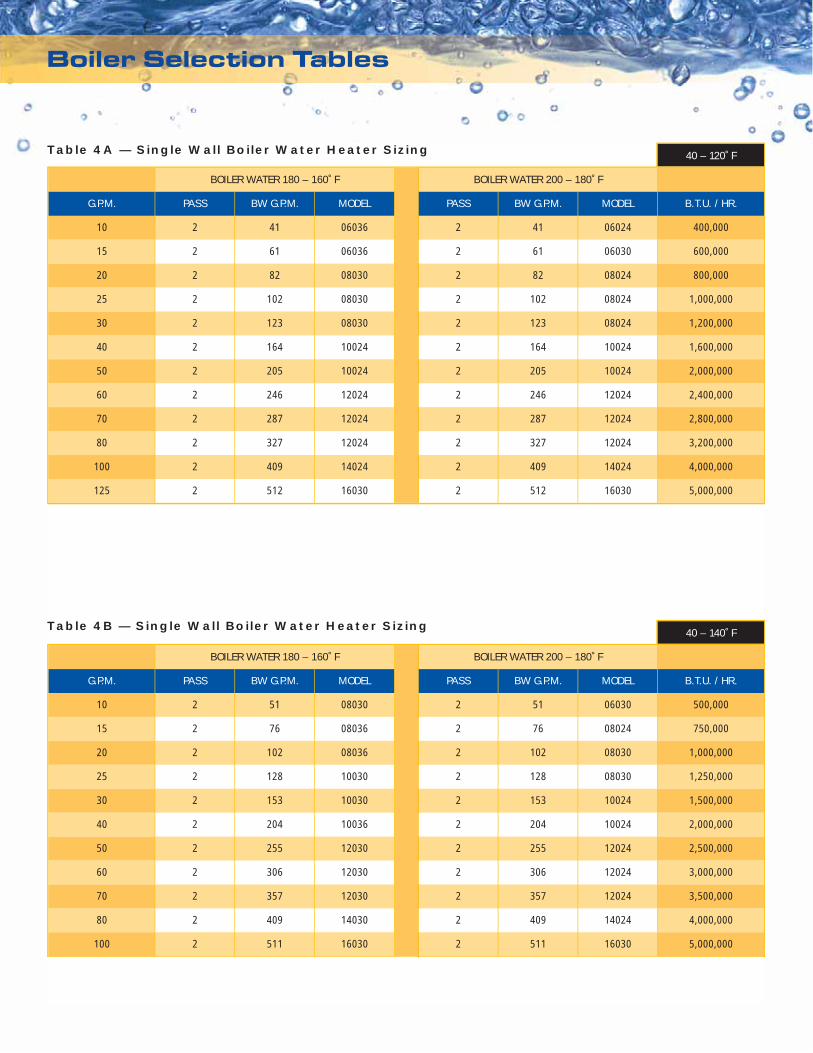
Table 4A — Single Wall Boiler Water Heater Sizing
Table 4B — Single Wall Boiler Water Heater Sizing
Boiler Selection Tables (cont.)
40 – 120˚F
G.P.M.
10
15
20
25
30
40
50
60
70
80
100
PASS
2
2
2
2
2
2
2
2
2
2
2
BW G.P.M.
41
61
82
102
123
164
205
246
287
327
409
MODEL
08036
08036
10030
10036
10036
10036
12030
12036
12036
14036
16030
BOILER WATER 180 – 160˚F BOILER WATER 200 – 180˚F
PASS
2
2
2
2
2
2
2
2
2
2
2
BW G.P.M.
41
61
82
102
123
164
205
246
287
327
409
MODEL
06036
08030
08030
08036
10030
10030
12024
12030
12030
14030
16024
B.T.U. / HR.
400,000
600,000
800,000
1,000,000
1,200,000
1,600,000
2,000,000
2,400,000
2,800,000
3,200,000
4,000,000
40 – 140˚F
G.P.M.
10
15
20
25
30
40
50
60
70
80
PASS
2
2
2
2
2
2
2
2
2
2
BW G.P.M.
51
76
102
128
153
204
255
306
357
409
MODEL
1036
1230
1236
1236
1436
1436
1636
1636
—
—
BOILER WATER 180 – 160˚F BOILER WATER 200 – 180˚F
PASS
2
2
2
2
2
2
2
2
2
2
BW G.P.M.
51
76
102
128
153
204
255
306
357
409
MODEL
836
1030
1030
1036
1036
1230
1236
1430
1436
1630
B.T.U. / HR.
500,000
750,000
1,000,000
1,250,000
1,500,000
2,000,000
2,500,000
3,000,000
3,500,000
4,000,000
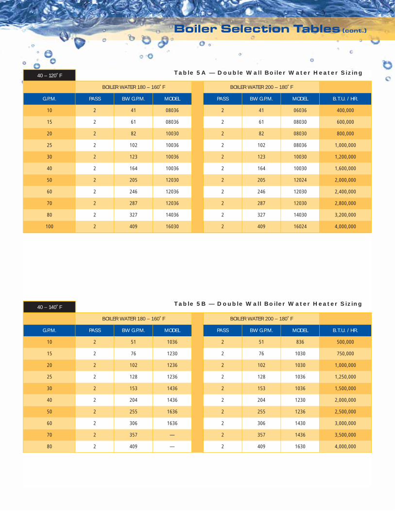
Table 5A — Double Wall Boiler Water Heater Sizing
Table 5B — Double Wall Boiler Water Heater Sizing
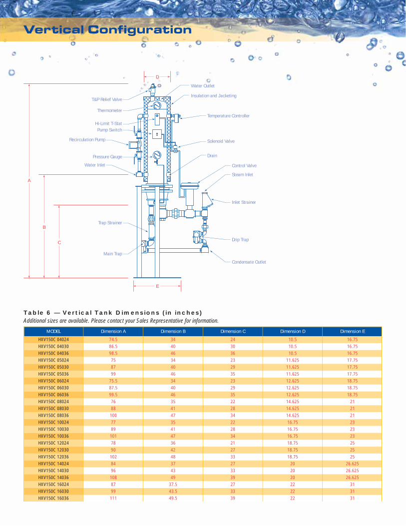
Vertical Configuration
MODEL
HXV150C 04024HXV150C 04030HXV150C 04036HXV150C 05024HXV150C 05030HXV150C 05036HXV150C 06024HXV150C 06030HXV150C 06036HXV150C 08024HXV150C 08030HXV150C 08036HXV150C 10024HXV150C 10030HXV150C 10036HXV150C 12024HXV150C 12030HXV150C 12036HXV150C 14024HXV150C 14030HXV150C 14036HXV150C 16024HXV150C 16030HXV150C 16036
Dimension A
74.586.598.5758799
75.587.599.57688
1007789
1017890
1028496
1088799
111
Dimension B
344046344046344046354147354147364248374349
37.543.549.5
Dimension C
243036232935232935222834222834212733273339273339
Dimension D
10.510.510.5
11.62511.62511.62512.62512.62512.62514.62514.62514.62516.7516.7516.7518.7518.7518.75
202020222222
Dimension E
16.7516.7516.7517.7517.7517.7518.7518.7518.75
212121232323252525
26.62526.62526.625
313131
Table 6 — Vertical Tank Dimensions (in inches)Additional sizes are available. Please contact your Sales Representative for information.
T&P Relief Valve
Water Outlet
Insulation and Jacketing
Thermometer
Hi-Limit T-StatPump Switch
Pressure Gauge
Trap Strainer
Main Trap
Water Inlet
Recirculation Pump
Temperature Controller
Solenoid Valve
Control Valve
Steam Inlet
Inlet Strainer
Condensate Outlet
Drip Trap
Drain
D
E
A
B
C
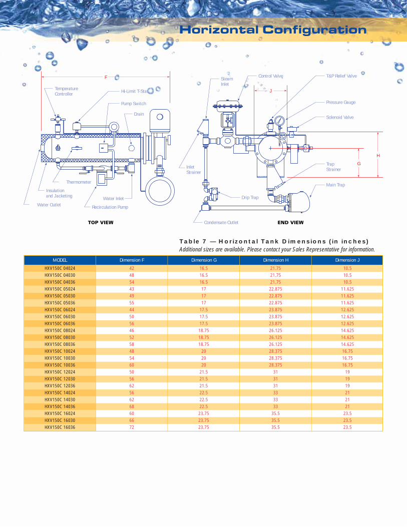
Horizontal Configuration
MODEL
HXV150C 04024HXV150C 04030HXV150C 04036HXV150C 05024HXV150C 05030HXV150C 05036HXV150C 06024HXV150C 06030HXV150C 06036HXV150C 08024HXV150C 08030HXV150C 08036HXV150C 10024HXV150C 10030HXV150C 10036HXV150C 12024HXV150C 12030HXV150C 12036HXV150C 14024HXV150C 14030HXV150C 14036HXV150C 16024HXV150C 16030HXV150C 16036
Dimension F
424854434955445056465258485460505662566268606672
Dimension G
16.516.516.5171717
17.517.517.5
18.7518.7518.75
202020
21.521.521.522.522.522.5
23.7523.7523.75
Dimension H
21.7521.7521.75
22.87522.87522.87523.87523.87523.87526.12526.12526.12528.37528.37528.375
313131333333
35.535.535.5
Dimension J
10.510.510.5
11.62511.62511.62512.62512.62512.62514.62514.62514.62516.7516.7516.75
191919212121
23.523.523.5
Table 7 — Horizontal Tank Dimensions (in inches)Additional sizes are available. Please contact your Sales Representative for information.
Water Outlet
TOP VIEW END VIEW
J
F
H
G
T&P Relief Valve
Insulationand Jacketing
Thermometer
Hi-Limit T-Stat
Pump Switch Pressure Gauge
TrapStrainer
Main Trap
Water Inlet
Recirculation Pump
TemperatureController
Control ValveSteamInlet
InletStrainer
Condensate Outlet
Drip Trap
DrainSolenoid Valve
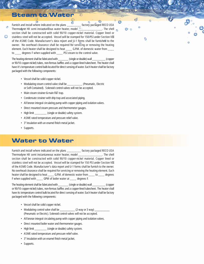
Steam to Water
Water to WaterFurnish and install where indicated on the plans _________ factory packaged RECO USAThermodyne HX semi instantaneous water heater, model _______________. The shellsection shall be constructed with solid 90/10 copper-nickel material. Copper lined orstainless steel will not be accepted. Vessel will be stamped for 150 PSI under Section VIIIof the ASME Code. Manufacturer’s data report and U-1 forms shall be furnish to the owner.No overhead clearance shall be required for servicing or removing the heating element. Eachheater shall be designed to heat ____ G.P.M. of domestic water from ____ to ____ degreesF when supplied with ____ GPM of boiler water at ____ degrees F.
The heating element shall be fabricated with _______ (single or double) wall _________ (copperor 90/10 copper-nickel) tubes, non-ferrous baffles and a copper-lined tubesheet. The heater shallhave its temperature control bulb located for direct sensing of water. Each heater shall be factorypackaged with the following components:
• Vessel shall be solid copper nickel.
• Modulating control valve shall be __________ (2-way or 3 way) __________(Pneumatic or Electric). Solenoid control valves will not be accepted.
• All bronze integral circulating pump with copper piping and isolation valves.
• Direct mounted boiler water and thermometer gauges.
• High limit ________ (single or double) safety system.
• ASME rated temperature and pressure relief valve.
• 3" insulation with an enamel finish metal jacket.
• Supports.
Furnish and install where indicated on the plans _________ factory packaged RECO USAThermodyne HX semi instantaneous water heater, model _______________. The shellsection shall be constructed with solid 90/10 copper-nickel material. Copper lined orstainless steel will not be accepted. Vessel will be stamped for 150 PSI under Section VIIIof the ASME Code. Manufacturer’s data report and U-1 forms shall be furnished to theowner. No overhead clearance shall be required for servicing or removing the heatingelement. Each heater shall be designed to heat ____ G.P.M. of domestic water from ____to ____ degrees F when supplied with ____ PSI steam to the control valve.
The heating element shall be fabricated with _______ (single or double) wall _________ (copperor 90/10 copper-nickel) tubes, non-ferrous baffles and a copper-lined tubesheet. The heater shallhave it’s temperature control bulb located for direct sensing of water. Each heater shall be factorypackaged with the following components:
• Vessel shall be solid copper nickel.
• Modulating steam control valve shall be __________ (Pneumatic, Electricor Self-Contained). Solenoid control valves will not be accepted.
• Main steam strainer & main F&T trap.
• Condensate strainer with drip trap and associated piping.
• All bronze integral circulating pump with copper piping and isolation valves.
• Direct mounted steam pressure and thermometer gauges.
• High limit ________ (single or double) safety system.
• ASME rated temperature and pressure relief valve.
• 3" insulation with an enamel finish metal jacket.
• Supports.
LE
GE
ND
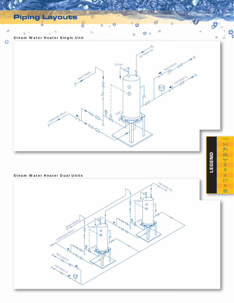
To Drain
Condensate Return
Steam Supply
Hot Water Out
Recirculation
Cold Water In
Drain
Hot Water Out
To Drain
To Drain
Drain
Drain
Steam Supply
Condensate Return
Recirculation
Cold Water In
Piping Layouts
Steam Water Heater Single Unit
Steam Water Heater Dual Units
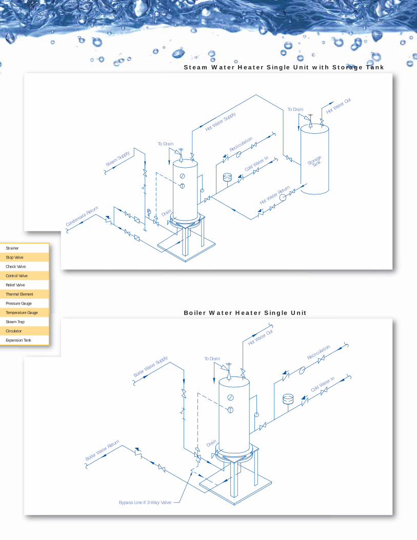
Bypass Line if 3-Way Valve
To Drain
Boiler Water Return
Boiler Water Supply
Hot Water Out
Recirculation
Cold Water In
Drain
Condensate Return
Steam Supply
Hot Water Supply Hot W
ater Out
Hot Water Return
Storage
Tank
Recirculation
Cold Water In
To Drain
To Drain
Drain
Strainer
Stop Valve
Check Valve
Control Valve
Relief Valve
Thermal Element
Pressure Gauge
Temperature Gauge
Steam Trap
Circulator
Expansion Tank
Steam Water Heater Single Unit with Storage Tank
Boiler Water Heater Single Unit
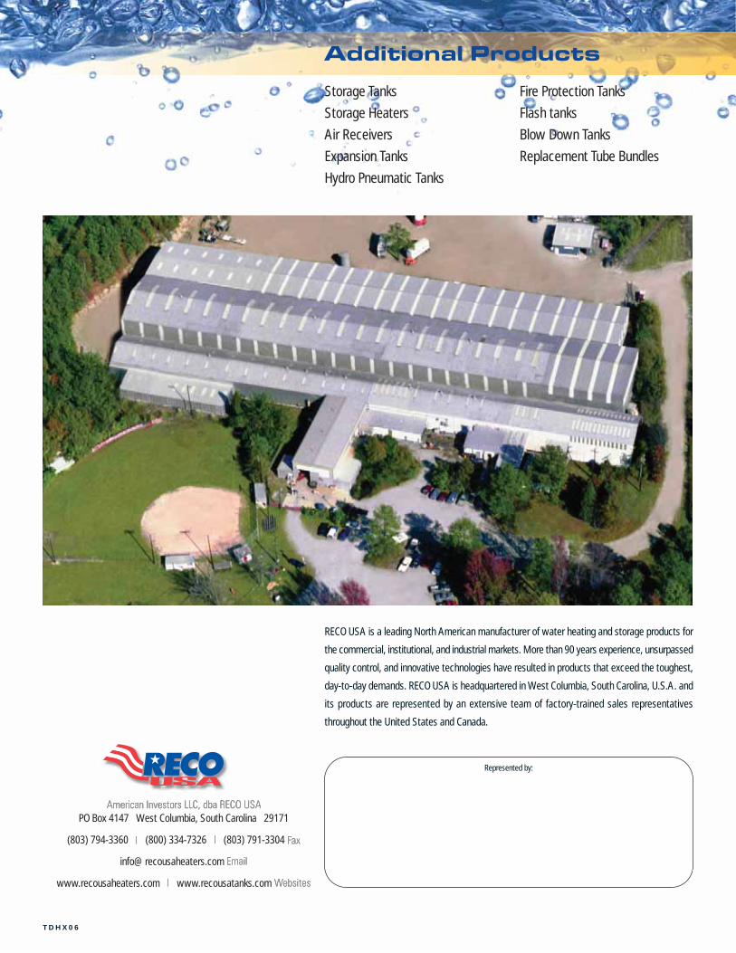
Additional Products
RECO USA is a leading North American manufacturer of water heating and storage products for
the commercial, institutional, and industrial markets. More than 90 years experience, unsurpassed
quality control, and innovative technologies have resulted in products that exceed the toughest,
day-to-day demands. RECO USA is headquartered in West Columbia, South Carolina, U.S.A. and
its products are represented by an extensive team of factory-trained sales representatives
throughout the United States and Canada.
Storage Tanks
Storage Heaters
Air Receivers
Expansion Tanks
Hydro Pneumatic Tanks
Fire Protection Tanks
Flash tanks
Blow Down Tanks
Replacement Tube Bundles
Represented by:
TDHX06
PO Box 4147 West Columbia, South Carolina 29171
(803) 794-3360 (800) 334-7326 (803) 791-3304
www.recousaheaters.com www.recousatanks.com