Embed Size (px)
Citation preview
Thermodynamicsprocesses and cycles
Rudolf Žitný, Ústav procesní a zpracovatelské techniky ČVUT FS 2010
HEAT PROCESSESTZ2HP2
Thermodynamics fundamentals. State variables, Gibbs phase rule, state equations, internal energy, enthalpy, entropy. First law and the second law of thermodynamics. Phase changes and phase diagrams. Ts and hs diagrams (example: Ts diagrams for air). Thermodynamic cycles Carnot, Clausius Rankine, Ericson, Stirling, thermoacoustics.
BASIC NOTIONSTZ1
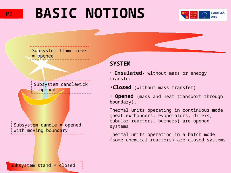
SYSTEM
• Insulated- without mass or energy transfer
•Closed (without mass transfer)
• Opened (mass and heat transport through boundary).
Thermal units operating in continuous mode (heat exchangers, evaporators, driers, tubular reactors, burners) are opened systems
Thermal units operating in a batch mode (some chemical reactors) are closed systems
Subsystem stand = closed
Subsystem candle = opened with moving boundary
Subsystem candlewick = opened
Subsystem flame zone = opened
HP2
StaTE VARIABLESTZ1
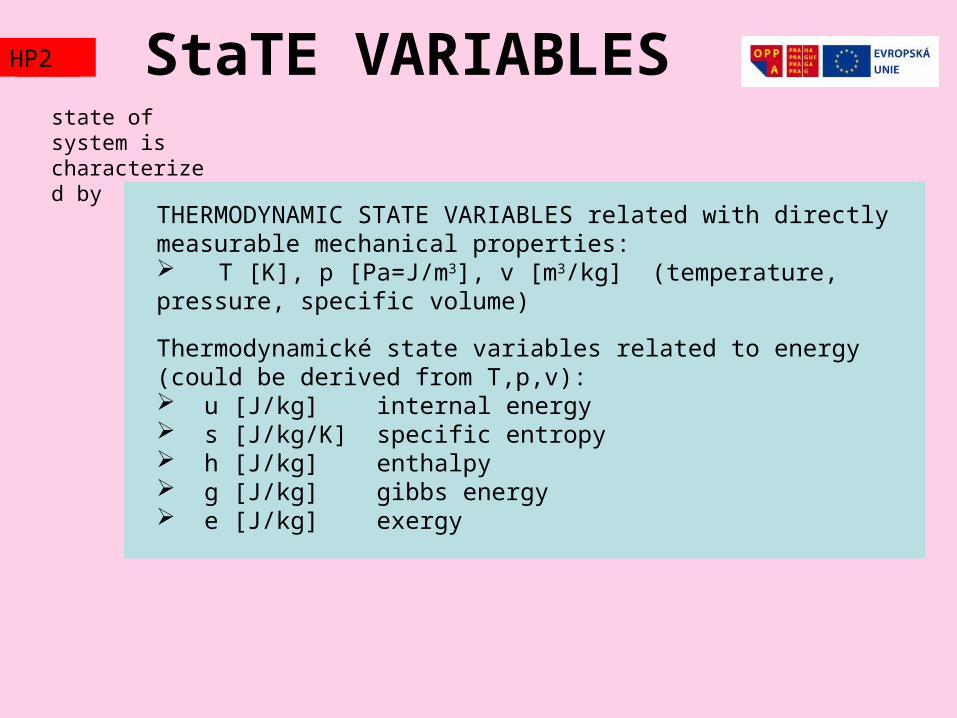
THERMODYNAMIC STATE VARIABLES related with directly measurable mechanical properties: T [K], p [Pa=J/m3], v [m3/kg] (temperature, pressure, specific volume)
Thermodynamické state variables related to energy (could be derived from T,p,v): u [J/kg] internal energy s [J/kg/K] specific entropy h [J/kg] enthalpy g [J/kg] gibbs energy e [J/kg] exergy
state of system is characterized by
HP2
Gibbs phase rule
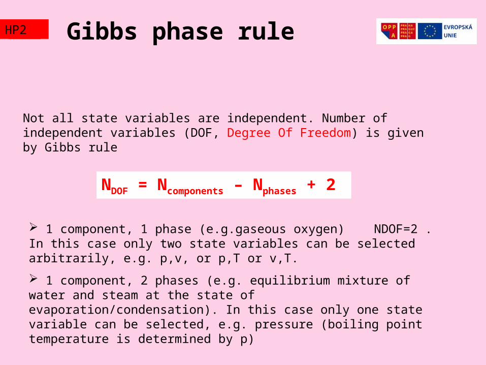
Not all state variables are independent. Number of independent variables (DOF, Degree Of Freedom) is given by Gibbs rule
NDOF = Ncomponents – Nphases + 2
1 component, 1 phase (e.g.gaseous oxygen) NDOF=2 . In this case only two state variables can be selected arbitrarily, e.g. p,v, or p,T or v,T.
1 component, 2 phases (e.g. equilibrium mixture of water and steam at the state of evaporation/condensation). In this case only one state variable can be selected, e.g. pressure (boiling point temperature is determined by p)
TZ1HP2
TZ2 State EquATIONS p-v-THP2
0)~(
2~6
~
0)~(~
2~
342
2
23
bv
RT
v
a
v
p
bv
RT
v
a
v
p
c
c
c
c
c
c
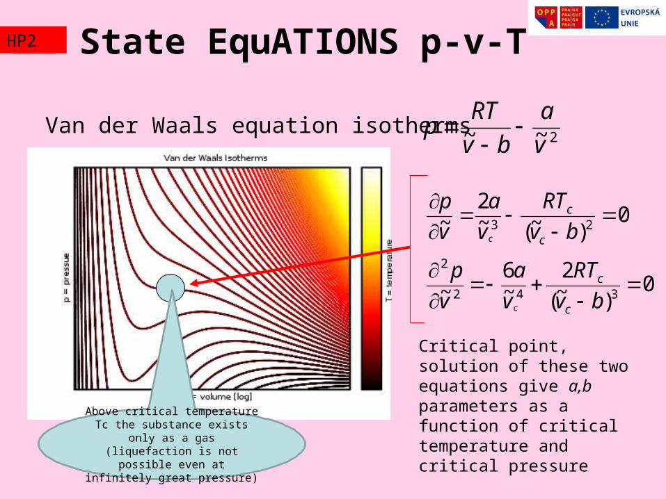
Van der Waals equation isotherms2~~ v
a
bv
RTp
Critical point, solution of these two equations give a,b parameters as a function of critical temperature and critical pressureAbove critical temperature Tc the
substance exists only as a gas (liquefaction is not possible even at
infinitely great pressure)
Pv=RT tutorial Baloon
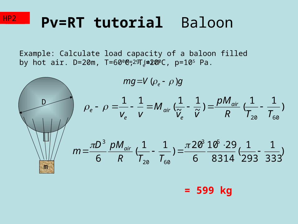
Example: Calculate load capacity of a baloon filled by hot air. D=20m, T=600C, Te=200C, p=105 Pa.
gVmg e )(
)11
()~1
~1
(11
6020 TTR
pM
vvM
vvair
eair
ee D
m
M=29 (air)
)333
1
293
1(
8314
2910
6
20)
11(
6
53
6020
3
TTR
pMDm air
= 599 kg
TZ2HP2
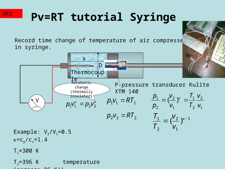
Pv=RT tutorial Syringe
P-pressure transducer Kulite XTM 140
Record time change of temperature of air compressed in syringe.
2211 vpvp 111 RTvp
222 RTvp
V
xD
1
2
2
1
1
2
2
1 )(v
v
T
T
v
v
p
p
1
1
2
2
1 )(
v
v
T
T
Thermocouple
Example: V2/V1=0.5 =cp/cv=1.4
T1=300 K
T2=396 K temperature increase 96 K!!
TZ2HP2
Adiabatic change (thermally insulated)
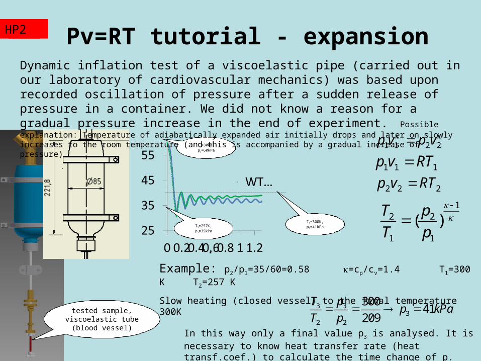
Pv=RT tutorial - expansion
2211 vpvp
111 RTvp
222 RTvp 1
2 2
1 1
( )T p
T p
Example: p2/p1=35/60=0.58 =cp/cv=1.4 T1=300 K T2=257 K
Slow heating (closed vessel) to the final temperature 300K
TZ2HP2
tested sample, viscoelastic tube (blood
vessel)
3 33
2 2
30041
209
T pp kPa
T p
T1=300K, p1=60kPa
T2=257K, p2=35kPa
T3=300K, p3=41kPa
Dynamic inflation test of a viscoelastic pipe (carried out in our laboratory of cardiovascular mechanics) was based upon recorded oscillation of pressure after a sudden release of pressure in a container. We did not know a reason for a gradual pressure increase in the end of experiment. Possible explanation: Temperature of adiabatically expanded air initially drops and later on slowly increases to the room temperature (and this is accompanied by a gradual increase of pressure) .
In this way only a final value p3 is analysed. It is necessary to know heat transfer rate (heat transf.coef.) to calculate the time change of p.
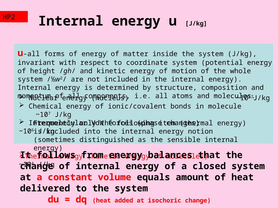
Internal energy u [J/kg]
u-all forms of energy of matter inside the system (J/kg), invariant with respect to coordinate system (potential energy of height /gh/ and kinetic energy of motion of the whole system /½w2/ are not included in the internal energy). Internal energy is determined by structure, composition and momentum of all components, i.e. all atoms and molecules. Nuclear energy (nucleus) ~1017J/kg Chemical energy of ionic/covalent bonds in molecule ~107 J/kg Intermolecular VdW forces (phase changes) ~106 J/kg
Thermal energy (kinetic energy of molecules) ~104 J/kg
It follows from energy balances that the change of internal energy of a closed system at a constant volume equals amount of heat delivered to the system
du = dq (heat added at isochoric change)
TZ2HP2
Frequently only the following item (thermal energy) is included into the internal energy notion (sometimes distinguished as the sensible internal energy)

Enthalpy h [J/kg]
h=u+pv
enthalpy is always greater than the internal energy. The added term pv (pressure multiplied by specific volume) simplifies energy balancing of continuous systems. The pv term automatically takes into account mechanical work (energy) necessary to push/pull the inlet/outlet material streams to/from the balanced system.
It follows from energy balances that the change of enthalpy of a closed system at a constant pressure equals amount of heat delivered to the system
dh = dq (heat added at isobaric change)
TZ2HP2
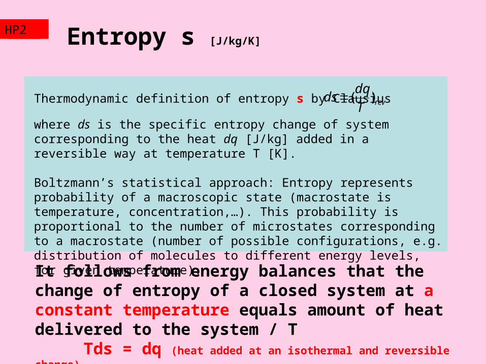
Entropy s [J/kg/K]
Thermodynamic definition of entropy s by Clausius
where ds is the specific entropy change of system corresponding to the heat dq [J/kg] added in a reversible way at temperature T [K].
Boltzmann’s statistical approach: Entropy represents probability of a macroscopic state (macrostate is temperature, concentration,…). This probability is proportional to the number of microstates corresponding to a macrostate (number of possible configurations, e.g. distribution of molecules to different energy levels, for given temperature).
It follows from energy balances that the change of entropy of a closed system at a constant temperature equals amount of heat delivered to the system / T
Tds = dq (heat added at an isothermal and reversible change)
revT
dqds )(
TZ2HP2
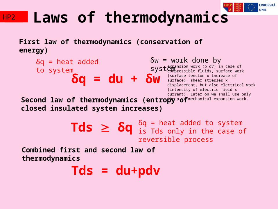
TZ2 Laws of thermodynamicsHP2
δq = heat added to system
δw = work done by system
δq = du + δw
First law of thermodynamics (conservation of energy)
δq = heat added to system is Tds only in the case of reversible processTds δq
Second law of thermodynamics (entropy of closed insulated system increases)
Combined first and second law of thermodynamics
Tds = du+pdv
expansion work (p.dV) in case of compressible fluids, surface work (surface tension x increase of surface), shear stresses x displacement, but also electrical work (intensity of electric field x current). Later on we shall use only the p.dV mechanical expansion work.
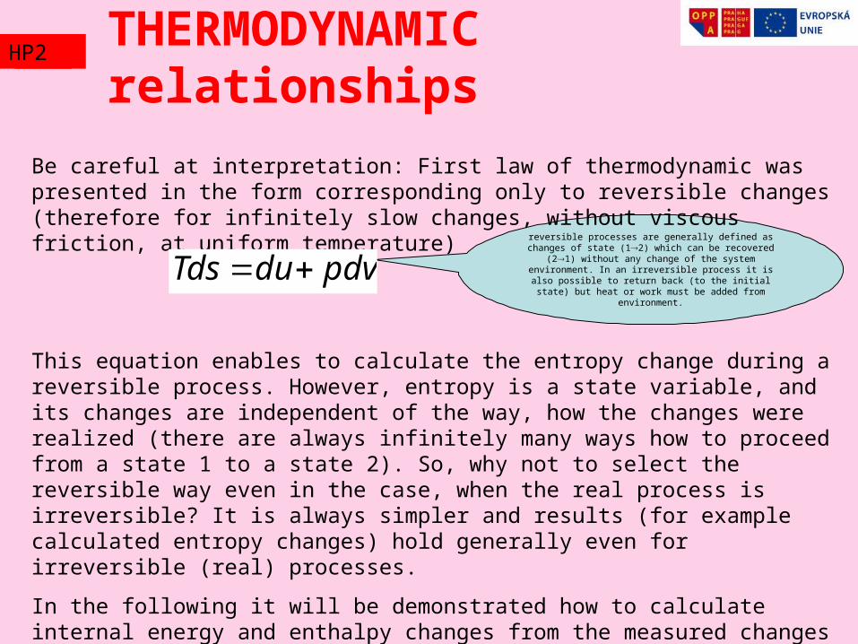
reversible processes are generally defined as changes of state (12) which can be recovered (21) without
any change of the system environment. In an irreversible process it is also possible to return back (to the initial state) but heat or work must be added from
environment.
Be careful at interpretation: First law of thermodynamic was presented in the form corresponding only to reversible changes (therefore for infinitely slow changes, without viscous friction, at uniform temperature)
This equation enables to calculate the entropy change during a reversible process. However, entropy is a state variable, and its changes are independent of the way, how the changes were realized (there are always infinitely many ways how to proceed from a state 1 to a state 2). So, why not to select the reversible way even in the case, when the real process is irreversible? It is always simpler and results (for example calculated entropy changes) hold generally even for irreversible (real) processes.
In the following it will be demonstrated how to calculate internal energy and enthalpy changes from the measured changes of temperature, pressure and volume (and results hold not only for the reversible processes).
pdvduTds
THERMODYNAMIC relationshipsTZ2HP2
0TdS dU pdV
Example: insulated systemTZ2HP2
Metal Tm=273K
Water Tw=300K
dQwm
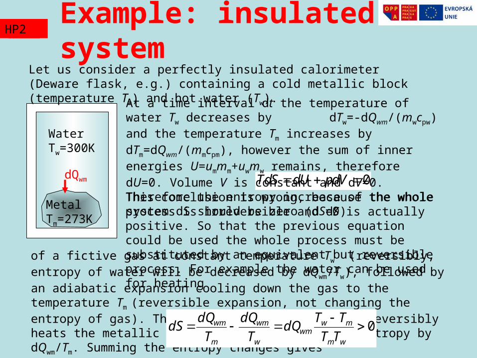
Let us consider a perfectly insulated calorimeter (Deware flask, e.g.) containing a cold metallic block (temperature Tm) and hot water (Tw).
At a time interval dt the temperature of water Tw decreases by dTw=-dQwm/(mwcpw) and the temperature Tm increases by dTm=dQwm/(mmcpm), however the sum of inner energies U=ummm+uwmw remains, therefore dU=0. Volume V is constant and dV=0. Therefore the entropy increase of the whole system dS should be zero (dS=0) This conclusion is wrong, because the whole process is irreversible and dS is actually positive. So that the previous equation could be used the whole process must be substituted by an equivalent but reversible process. For example the water can be used for heating
of a fictive gas at constant temperature Tw (reversibly, entropy of water will be decreased by dQwm/Tw), followed by an adiabatic expansion cooling down the gas to the temperature Tm (reversible expansion, not changing the entropy of gas). The gas then isothermally and reversibly heats the metallic block, thus increasing its entropy by dQwm/Tm. Summing the entropy changes gives 0
wm
mwwm
w
wm
m
wm
TT
TTdQ
T
dQ
T
dQdS
The temperature increase increases thermal energy (kinetic energy of molecules).
For constant volume (fixed volume of system) internal energy change is proportional to the change of thermodynamic temperature (Kelvins)
du = cv dT where cv is specific heat at constant volume
For constant pressure (e.g. atmospheric pressure) the enthalpy change is also proportional to the thermodynamic temperature
dh = cp dT where cp is specific heat at constant pressure.
Specific heat at a constant pressure is always greater than the specific heat at a constant volume (it is always necessary to supply more heat to increase temperature at constant pressure, because part of the delivered energy is converted to the volume increase, therefore to the mechanical work). Only for incompressible materials it holds cp=cv.
Energies and Temperature TZ2HP2
Energies and Temperature TZ2HP2
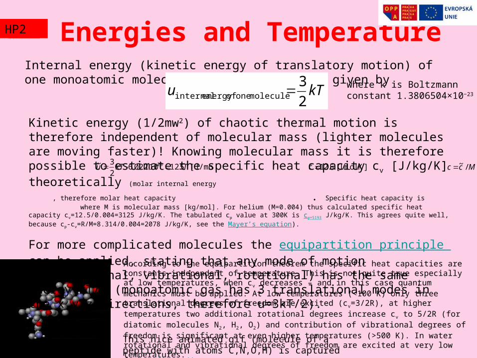
This nice animated gif (molecule of a peptide with atoms C,N,O,H) is captured from Wikipedia.org
Internal energy (kinetic energy of translatory motion) of one monoatomic molecule of an ideal gas is given by
kTu2
3molecule one ofenergy internal where k is Boltzmann constant
1.3806504×10⁻²³
Kinetic energy (1/2mw2) of chaotic thermal motion is therefore independent of molecular mass (lighter molecules are moving faster)! Knowing molecular mass it is therefore possible to estimate the specific heat capacity cv [J/kg/K] theoretically (molar internal energy , therefore molar heat capacity . Specific heat capacity is where M is molecular mass [kg/mol]. For helium (M=0.004) thus calculated specific heat capacity cv=12.5/0.004=3125 J/kg/K. The tabulated cp value at 300K is cp=5193 J/kg/K. This agrees quite well, because cp-cv=R/M=8.314/0.004=2078 J/kg/K, see the Mayer’s equation).
For more complicated molecules the equipartition principle can be applied, stating that any mode of motion (translational, vibrational, rotational) has the same energy kT/2 (monoatomic gas has 3 translational modes in the x,y,z directions, therefore u=3kT/2).
According to the equipartition theorem the specific heat capacities are constants independent of temperature. This is not quite true especially at low temperatures, when cv decreases – and in this case quantum mechanics must be applied. At low temperatures (<100 K) only three translational degrees of freedom are excited (cv=3/2R), at higher temperatures two additional rotational degrees increase cv to 5/2R (for diatomic molecules N2, H2, O2) and contribution of vibrational degrees of freedom is significant at even higher temperatures (>500 K). In water rotational and vibrational degrees of freedom are excited at very low temperatures.
[J/mol] 5.1210022.62
3~ 23 TkTu 12.5 [J/mol/K]c Mcc /~
Energies and Temperature TZ2HP2
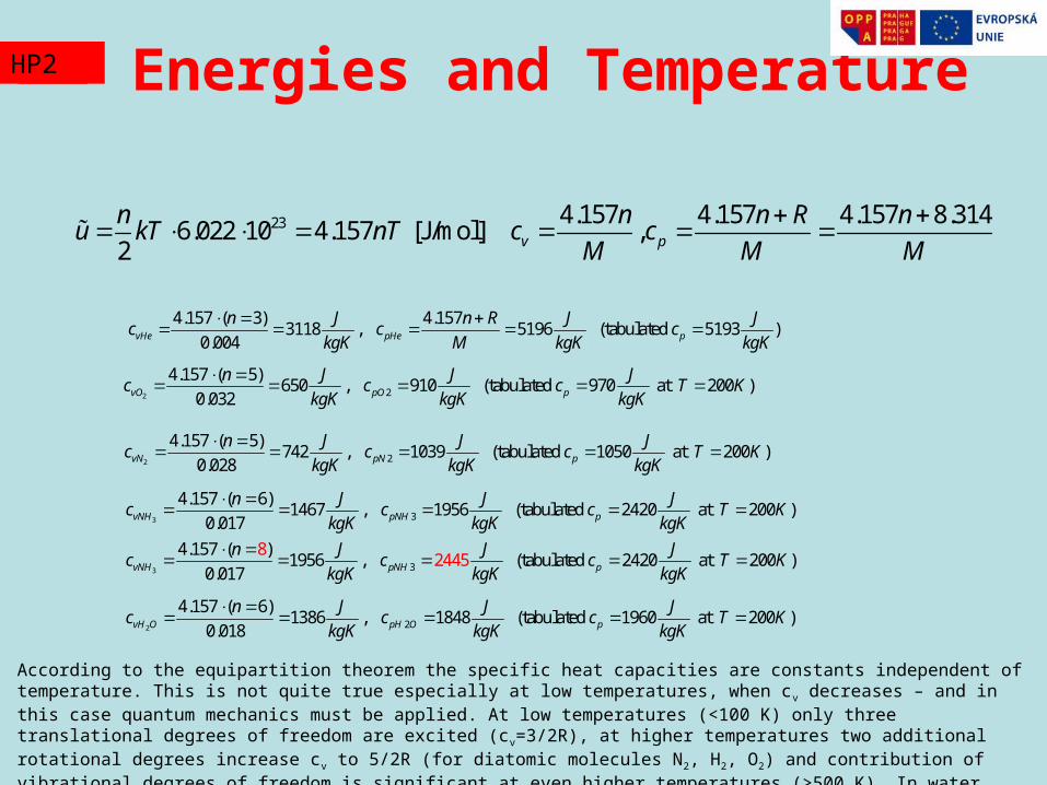
According to the equipartition theorem the specific heat capacities are constants independent of temperature. This is not quite true especially at low temperatures, when cv decreases – and in this case quantum mechanics must be applied. At low temperatures (<100 K) only three translational degrees of freedom are excited (cv=3/2R), at higher temperatures two additional rotational degrees increase cv to 5/2R (for diatomic molecules N2, H2, O2) and contribution of vibrational degrees of freedom is significant at even higher temperatures (>500 K). In water rotational and vibrational degrees of freedom are excited at very low temperatures.
23 4.157 4.157 4.157 8.3146.022 10 4.157 [J/mol] ,
2 v p
n n n R nu kT nT c c
M M M
4.157 ( 3) 4.1573118 , 5196 (tabulated 5193 )
0.004vHe pHe p
n J n R J Jc c c
kgK M kgK kgK
2 2
4.157 ( 5)650 , 910 (tabulated 970 at 200 )
0.032vO pO p
n J J Jc c c T K
kgK kgK kgK
2 2
4.157 ( 5)742 , 1039 (tabulated 1050 at 200 )
0.028vN pN p
n J J Jc c c T K
kgK kgK kgK
3
3
3
3
4.157 ( 6)1467 , 1956 (tabulated 2420 at 200 )
0.017
4.157 ( )1956 ,
82445 (tabulated 2420 at 200 )
0.017
vNH pNH p
vNH pNH p
n J J Jc c c T K
kgK kgK kgK
n J J Jc c c T K
kgK kgK kgK
2 2
4.157 ( 6)1386 , 1848 (tabulated 1960 at 200 )
0.018vH O pH O p
n J J Jc c c T K
kgK kgK kgK
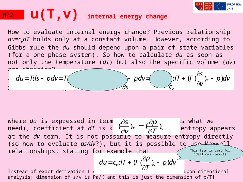
How to evaluate internal energy change? Previous relationship du=cvdT holds only at a constant volume. However, according to Gibbs rule the du should depend upon a pair of state variables (for a one phase system). So how to calculate du as soon as not only the temperature (dT) but also the specific volume (dv) are changing?
Solution is based upon the 1st law of thermodynamic (for reversible changes)
where du is expressed in terms dT and dv (this is what we need), coefficient at dT is known (cv), however entropy appears at the dv term. It is not possible to measure entropy directly (so how to evaluate ds/dv?), but it is possible to use Maxwell relationships, stating for example that
Instead of exact derivation I can give you only an idea based upon dimensional analysis: dimension of s/v is Pa/K and this is just the dimension of p/T!
So there is the final result
u(T,v) internal energy change
dvpT
pTdTcdu vv ))((
dvpv
sTdT
T
sTpdvdv
v
sdT
T
sTpdvTdsdu TvTv ))(()())()((
vT T
p
v
s)()(
This term is zero for ideal gas (pv=RT)
cvds
TZ2HP2
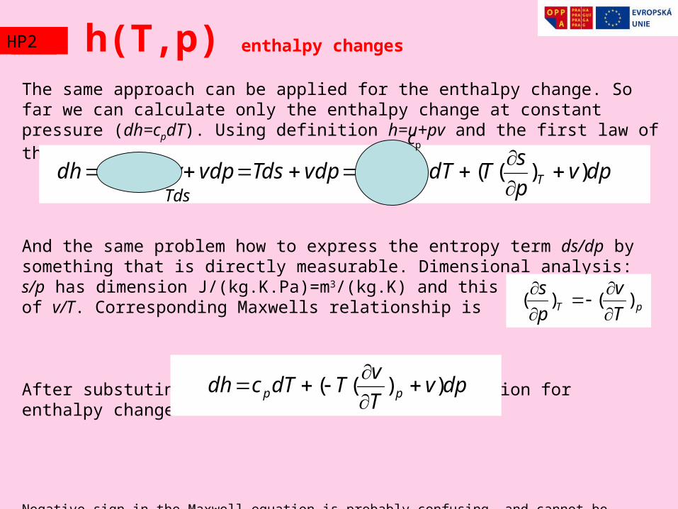
The same approach can be applied for the enthalpy change. So far we can calculate only the enthalpy change at constant pressure (dh=cpdT). Using definition h=u+pv and the first law of thermodynamics
And the same problem how to express the entropy term ds/dp by something that is directly measurable. Dimensional analysis: s/p has dimension J/(kg.K.Pa)=m3/(kg.K) and this is dimension of v/T. Corresponding Maxwells relationship is
After substuting we arrive to the final expression for enthalpy change
Negative sign in the Maxwell equation is probably confusing, and cannot be derived from dimensional analysis. Correct derivation is presented in the following slide.
h(T,p) enthalpy changes
dpvp
sTdT
T
sTvdpTdsvdppdvdudh Tp ))(()(
dpvT
vTdTcdh pp ))((
pT T
v
p
s)()(
cp
Tds
TZ2HP2

Basic idea consists in design of a state function with total differential depending only upon dT and dp . Such a function is Gibbs energy g (previously free enthalpy)
Notice the fact, that using this combination of enthalpy and entropy (h-Ts) the differentials dh and ds are mutually cancelled. Comparing coefficients at dp and dT the partial derivatives of Gibbs energy can be expressed as
Because the mixed derivatives equal, the Maxwell equation follows
Tshg
dTT
gdp
p
gsdTvdpsdTTdsdhdg pT )()(
Tp
gv )(
Tp p
s
T
v
pT
g)()(
2
Maxwell relationships
pT
gs )(
TZ2HP2

Tshg Tp ps
Tv
)()(
Maxwell relationshipsTZ2HP2
Tsu Tv vs
Tp
)()(
u vs sp
vT
)()(
h ps sv
pT
)()(
For first law For incompressible elongation (f force positive when extended)
For magnetisation
0du Tds pdv Hd
H-intensity of magnetic. field-specific magnetisation0-magnetic permeability of vacuum
HT THs
)()( 0
TL LS
Tf
)()(
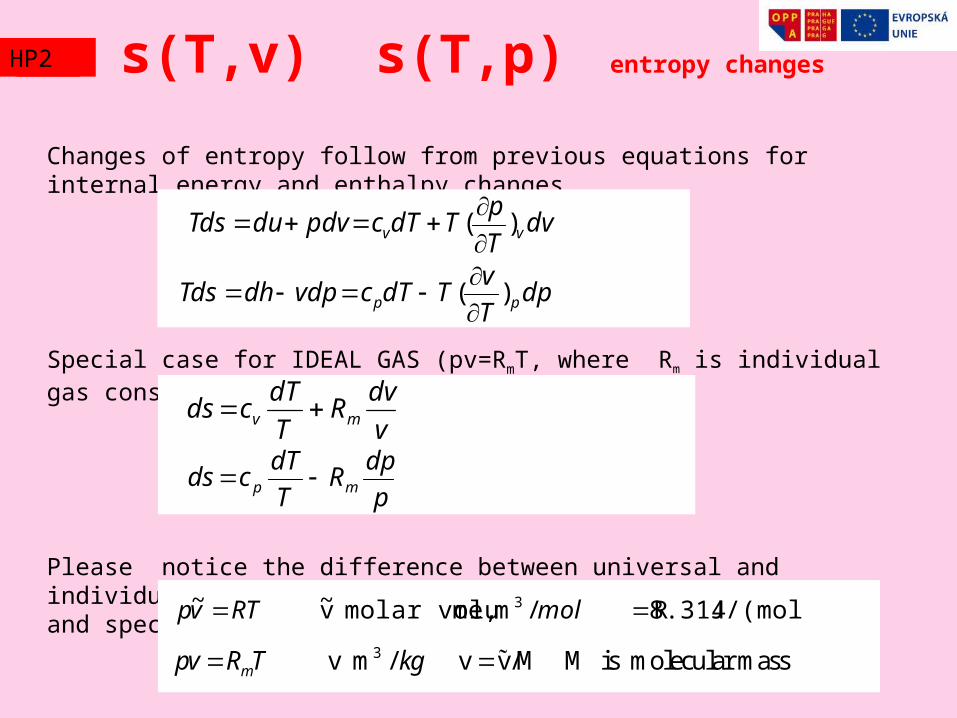
Changes of entropy follow from previous equations for internal energy and enthalpy changes
Special case for IDEAL GAS (pv=RmT, where Rm is individual gas constant)
Please notice the difference between universal and individual gas constant. And the difference between molar and specific volume.
dvT
pTdTcpdvduTds vv )(
dpT
vTdTcvdpdhTds pp )(
v
dvR
T
dTcds mv
J/(mol.K) 8.314 R/m me,molar volu v~ ~ 3 molRTvp
3 v m / v v/M M is molecular massmpv R T kg
p
dpR
T
dTcds mp
s(T,v) s(T,p) entropy changesTZ2HP2
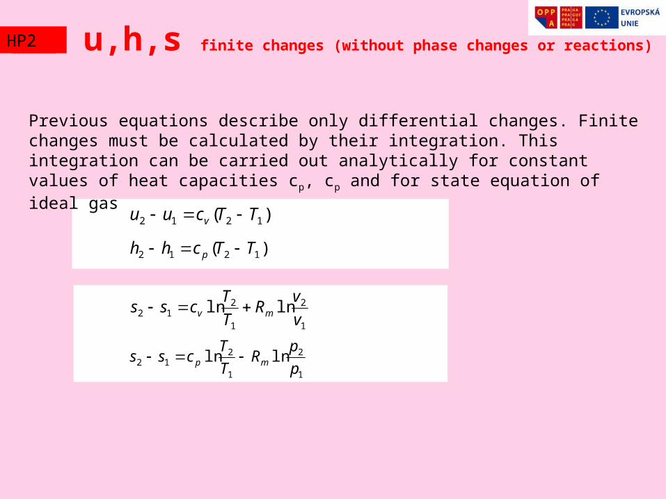
Previous equations describe only differential changes. Finite changes must be calculated by their integration. This integration can be carried out analytically for constant values of heat capacities cp, cp and for state equation of ideal gas
1
2
1
212 lnln
p
pR
T
Tcss mp
1
2
1
212 lnln
v
vR
T
Tcss mv
)( 1212 TTchh p
)( 1212 TTcuu v
u,h,s finite changes (without phase changes or reactions)TZ2HP2
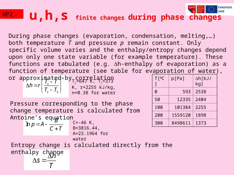
During phase changes (evaporation, condensation, melting,…) both temperature T and pressure p remain constant. Only specific volume varies and the enthalpy/entropy changes depend upon only one state variable (for example temperature). These functions are tabulated (e.g. h-enthalpy of evaporation) as a function of temperature (see table for evaporation of water), or approximated by correlation
1
n
c
c
T Th r
T T
lnB
p AC T
hs
T
u,h,s finite changes during phase changes
T[0C] p[Pa] h[kJ/kg]
0 593 2538
50 12335 2404
100 101384 2255
200 1559120 1898
300 8498611 1373
Tc=647 K, T1=373 K, r=2255 kJ/kg, n=0.38 for water
Pressure corresponding to the phase change temperature is calculated from Antoine’s equation
C=-46 K, B=3816.44, A=23.1964 for water
Entropy change is calculated directly from the enthalpy change
TZ2HP2
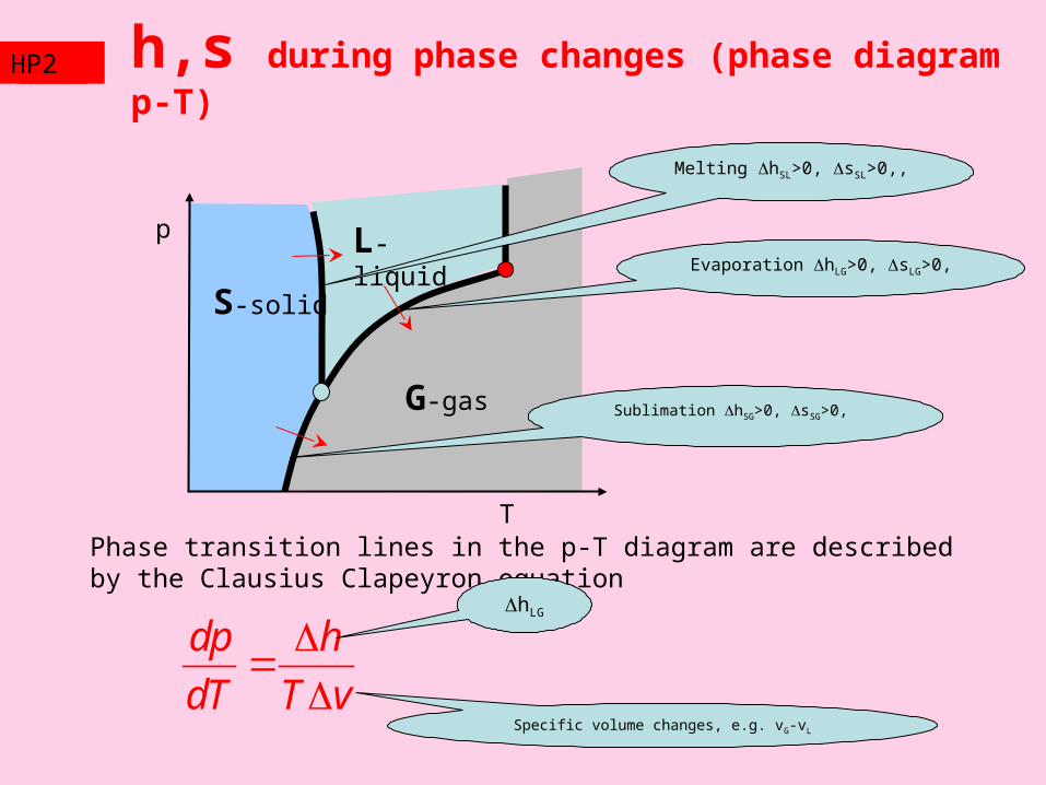
S-solid
L-liquid
G-gas
T
pEvaporation hLG>0, sLG>0,
Sublimation hSG>0, sSG>0,
Melting hSL>0, sSL>0,,
h,s during phase changes (phase diagram p-T)
Phase transition lines in the p-T diagram are described by the Clausius Clapeyron equation
dp h
dT T v
hLG
Specific volume changes, e.g. vG-vL
TZ2HP2
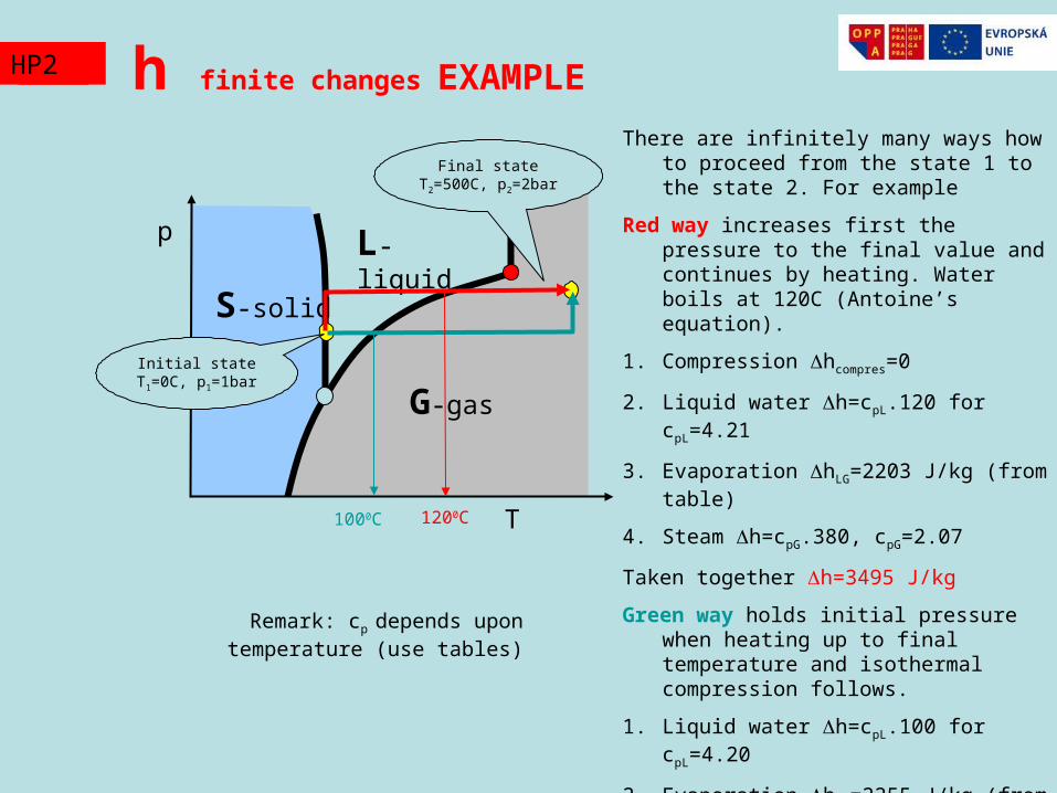
h finite changes EXAMPLE
S-solid
L-liquid
G-gas
T
p
TZ2HP2
Initial state T1=0C, p1=1bar
Final state T2=500C, p2=2bar
There are infinitely many ways how to proceed from the state 1 to the state 2. For example
Red way increases first the pressure to the final value and continues by heating. Water boils at 120C (Antoine’s equation).
1. Compression hcompres=0
2. Liquid water h=cpL.120 for cpL=4.21
3. Evaporation hLG=2203 J/kg (from table)
4. Steam h=cpG.380, cpG=2.07
Taken together h=3495 J/kg
Green way holds initial pressure when heating up to final temperature and isothermal compression follows.
1. Liquid water h=cpL.100 for cpL=4.20
2. Evaporation hLG=2255 J/kg (from table)
3. Steam h=cpG.400, cpG=2.05
4. Isothermal compression hcompres=0
Sum (1-4) gives the same result h=3495 J/kg
Remark: cp depends upon temperature (use tables)
1000C 1200C
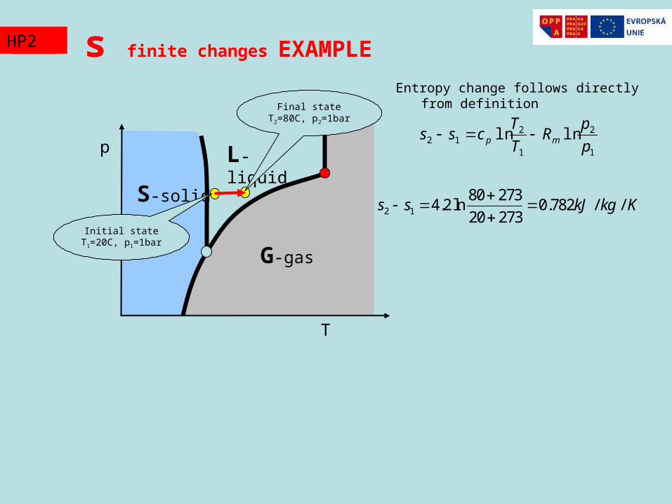
s finite changes EXAMPLE
S-solid
L-liquid
G-gas
T
p
TZ2HP2
Initial state T1=20C, p1=1bar
Final state T2=80C, p2=1bar
Entropy change follows directly from definition
1
2
1
212 lnln
p
pR
T
Tcss mp
2 1
80 2734.2 ln 0.782 / /
20 273s s kJ kg K
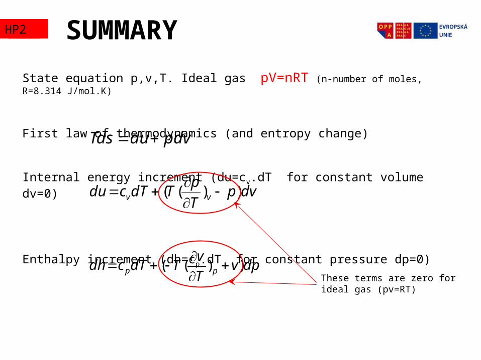
State equation p,v,T. Ideal gas pV=nRT (n-number of moles, R=8.314 J/mol.K)
First law of thermodynamics (and entropy change)
Internal energy increment (du=cv.dT for constant volume dv=0)
Enthalpy increment (dh=cp.dT for constant pressure dp=0)
SUMMARY
pdvduTds
dvpT
pTdTcdu vv ))((
dpvT
vTdTcdh pp ))((
These terms are zero for ideal gas (pv=RT)
TZ2HP2
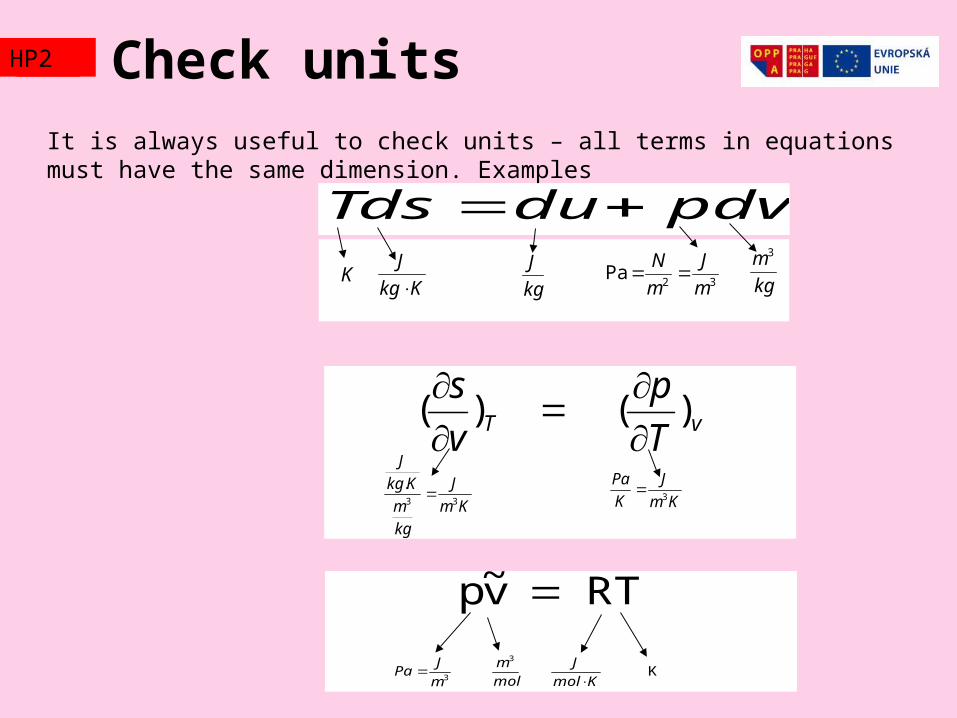
It is always useful to check units – all terms in equations must have the same dimension. Examples
Check units
pdvduTds
KKkg
J
kg
J 32
Pam
J
m
N
kg
m3
vT T
p
v
s)( )(
Km
J
kg
m
Kkg
J
33
. Km
J
K
Pa3
RT v~p
3m
JPa K
Kmol
J
mol
m3
TZ2HP2
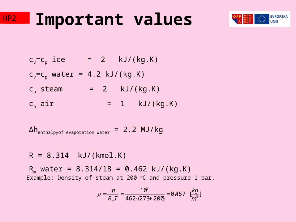
Important values
cv=cp ice = 2 kJ/(kg.K)
cv=cp water = 4.2 kJ/(kg.K)
cp steam = 2 kJ/(kg.K)
cp air = 1 kJ/(kg.K)
Δhenthalpyof evaporation water = 2.2 MJ/kg
R = 8.314 kJ/(kmol.K)
Rm water = 8.314/18 = 0.462 kJ/(kg.K)Example: Density of steam at 200 oC and pressure 1 bar.
][ 457.0)200273(462
103
5
m
kg
TR
p
m
TZ2HP2
THERMODYNAMICDIAGRAMS
TZ2HP2
Delvaux
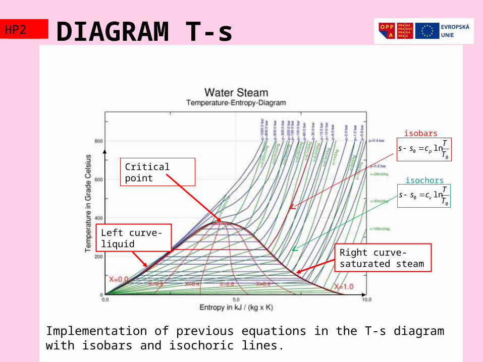
DIAGRAM T-s
Implementation of previous equations in the T-s diagram with isobars and isochoric lines.
Right curve-saturated steam
Critical point
TZ2HP2
00 ln
T
Tcss p
00 ln
T
Tcss v
Left curve-liquid
isobars
isochors
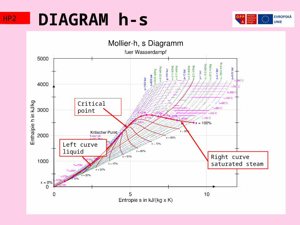
DIAGRAM h-s
Right curve saturated steam
Left curve liquid
Critical point
TZ2HP2
Thermodynamic processesTZ2HP2
Basic processes in thermal apparatuses are
Isobaric dp=0 (heat exchangers, ducts, continuous reactors)
Isoentropic ds=0 (adiabatic-thermally insulated apparatus, ideal flow without friction, enthalpy changes are fully converted to mechanical energy: compressors, turbines, nozzles)
Isoenthalpic dh=0 (also adiabatic without heat exchange with environment, but no mechanical work is done and pressure energy is dissipated to heat: throttling in reduction valves)
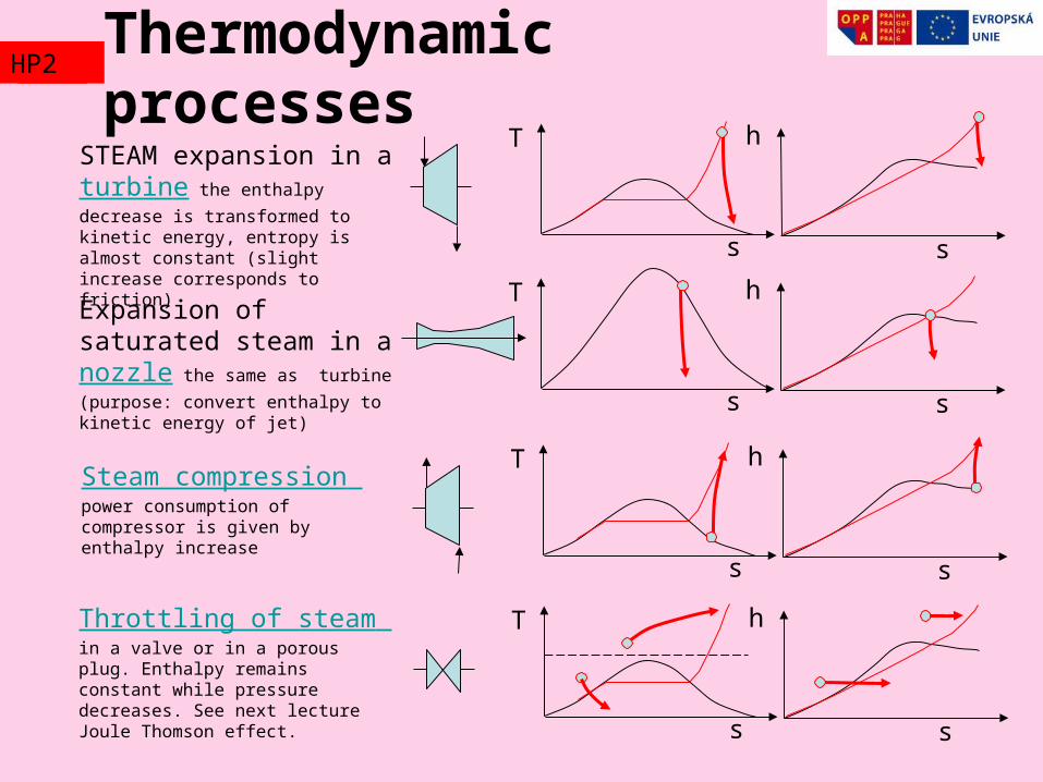
Thermodynamic processes
s
T
s
hSTEAM expansion in a turbine the enthalpy decrease is transformed to kinetic energy, entropy is almost constant (slight increase corresponds to friction)
s
T
s
hSteam compression power consumption of compressor is given by enthalpy increase
s
T
s
hThrottling of steam in a valve or in a porous plug. Enthalpy remains constant while pressure decreases. See next lecture Joule Thomson effect.
s
T
s
hExpansion of saturated steam in a nozzle the same as turbine (purpose: convert enthalpy to kinetic energy of jet)
TZ2HP2
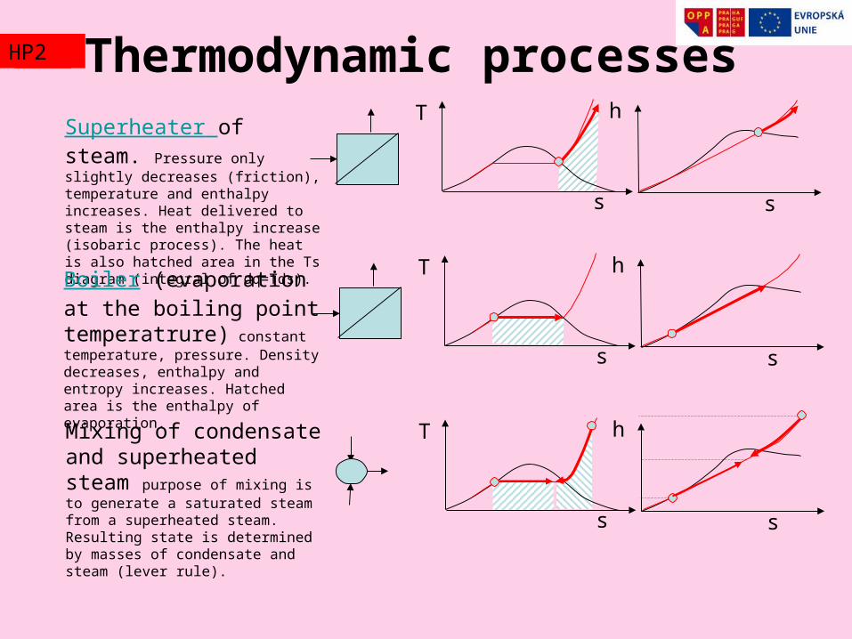
Thermodynamic processes
s
T
s
hSuperheater of steam. Pressure only slightly decreases (friction), temperature and enthalpy increases. Heat delivered to steam is the enthalpy increase (isobaric process). The heat is also hatched area in the Ts diagram (integral of dq=Tds).
s
T
s
hMixing of condensate and superheated steam purpose of mixing is to generate a saturated steam from a superheated steam. Resulting state is determined by masses of condensate and steam (lever rule).
Boiler (evaporation at the boiling point temperatrure) constant temperature, pressure. Density decreases, enthalpy and entropy increases. Hatched area is the enthalpy of evaporation.
s
T
s
h
TZ2HP2
Thermodynamic cyclesTZ2HP2
Periodically repeating processes with working fluid (water, hydrocarbons, CO2,…) when heat is supplied to the fluid in the first phase of the process followed by the second phase of heat removal (final state of the working medium is the same as the initial one, therefore the cycle can be repeated infinitely many times). Because more heat is supplied in the first phase than in the second phase, the difference is the mechanical work done by the working medium in a turbine (e.g.). It follows from the first law of thermodynamics.
Thermodynamic cycles
214 )( TssQ
))(( 1214 TTssW
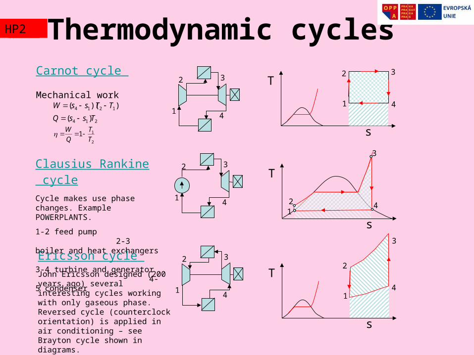
Carnot cycle
Mechanical work
Ericsson cycle John Ericsson designed (200 years ago) several interesting cycles working with only gaseous phase. Reversed cycle (counterclock orientation) is applied in air conditioning – see Brayton cycle shown in diagrams.
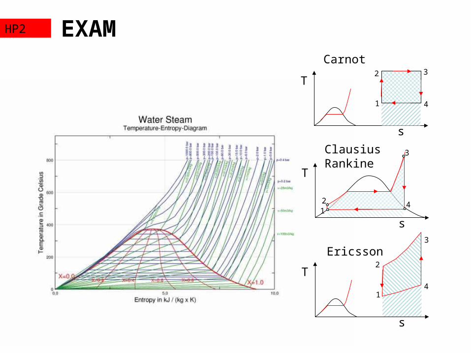
Clausius Rankine cycleCycle makes use phase changes. Example POWERPLANTS.
1-2 feed pump 2-3 boiler and heat exchangers 3-4 turbine and generator 4-5 condenser
s
T
1
2 3
41
2 3
4
1
2 3
4
2
11T
T
Q
W
1
2 3
4
s
T
1
2
3
4
s
T
12
3
4
TZ2HP2
Thermodynamic cyclesTZ2HP2
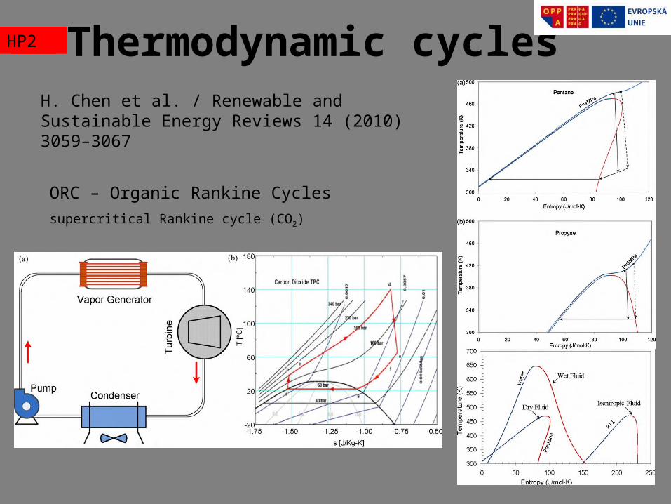
H. Chen et al. / Renewable and Sustainable Energy Reviews 14 (2010) 3059–3067
ORC – Organic Rankine Cycles
supercritical Rankine cycle (CO2)
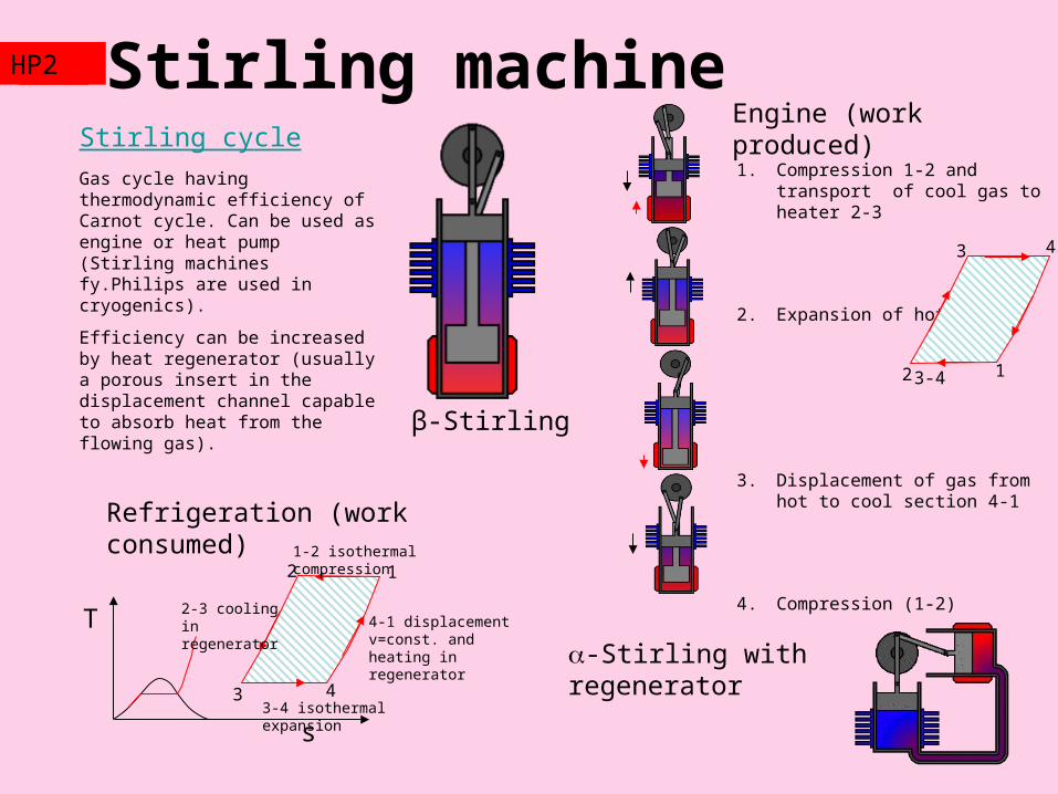
Stirling machineStirling cycleGas cycle having thermodynamic efficiency of Carnot cycle. Can be used as engine or heat pump (Stirling machines fy.Philips are used in cryogenics).
Efficiency can be increased by heat regenerator (usually a porous insert in the displacement channel capable to absorb heat from the flowing gas).
1. Compression 1-2 and transport of cool gas to heater 2-3
2. Expansion of hot gas 3-4
3. Displacement of gas from hot to cool section 4-1
4. Compression (1-2)
s
T
12
3 4
4-1 displacement v=const. and heating in regenerator
1-2 isothermal compression
2-3 cooling in regenerator
3-4 isothermal expansion
-Stirling with regenerator
β-Stirling
TZ2HP2
Engine (work produced)
Refrigeration (work consumed)
13
2 1
4
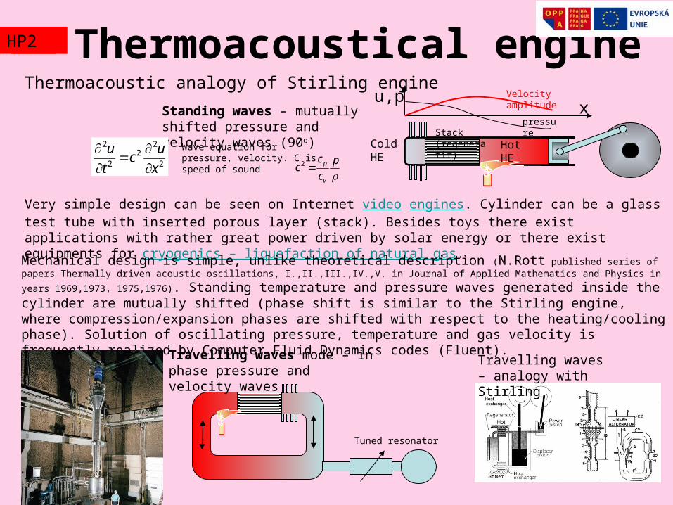
Thermoacoustic analogy of Stirling engine
Very simple design can be seen on Internet video engines. Cylinder can be a glass test tube with inserted porous layer (stack). Besides toys there exist applications with rather great power driven by solar energy or there exist equipments for cryogenics – liquefaction of natural gas.
Thermoacoustical engine
Mechanical design is simple, unlike theoretical description (N.Rott published series of papers Thermally driven acoustic
oscillations, I.,II.,III.,IV.,V. in Journal of Applied Mathematics and Physics in years 1969,1973, 1975,1976). Standing temperature and pressure waves generated inside the cylinder are mutually shifted (phase shift is similar to the Stirling engine, where compression/expansion phases are shifted with respect to the heating/cooling phase). Solution of oscillating pressure, temperature and gas velocity is frequently realized by Computer Fluid Dynamics codes (Fluent).
Tuned resonator
Travelling waves mode – in phase pressure and velocity waves
TZ2HP2
Travelling waves – analogy with Stirling
Standing waves – mutually shifted pressure and velocity waves (90o)
2
22
2
2
x
uc
t
u
Hot
HECold HE
Stack (regeneratir)
Velocity amplitude
pressurex
u,p
Wave equation for pressure, velocity. C is speed of sound
p
c
cc
v
p2
Thermoacoustics
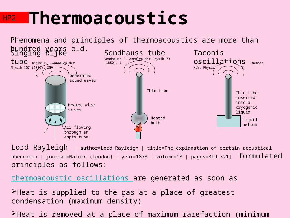
Lord Rayleigh | author=Lord Rayleigh | title=The explanation of certain acoustical phenomena | journal=Nature (London)
| year=1878 | volume=18 | pages=319–321] formulated principles as follows:
thermoacoustic oscillations are generated as soon as
Heat is supplied to the gas at a place of greatest condensation (maximum density)
Heat is removed at a place of maximum rarefaction (minimum pressure)
TZ2HP2
Phenomena and principles of thermoacoustics are more than hundred years old.
Heated wire screen
Air flowing through an empty tube
Generated sound waves
Singing Rijke tube Rijke P.L. Annalen der Physik 107 (1859), 339
Sondhauss tube Sondhauss C. Annalen der Physik 79 (1850), 1
Heated bulb
Thin tube
Taconis oscillations Taconis K.W. Physica 15 (1949) 738
Liquid helium
Thin tube inserted into a cryogenic liquid
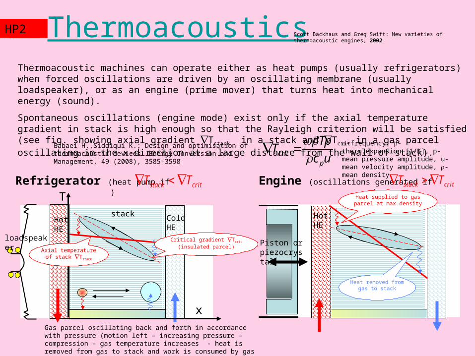
ThermoacousticsTZ2HP2 Scott Backhaus and Greg Swift: New varieties of thermoacoustic engines, 2002
Gas parcel oscillating back and forth in accordance with pressure (motion left – increasing pressure – compression – gas temperature increases - heat is removed from gas to stack and work is consumed by gas parcel)
x
T
Cold HE
Hot HE
Hot HE
loadspeaker
Engine (oscillations generated if )critstack TT Refrigerator (heat pump if )stack critT T
stack
Axial temperature of stack Tstack
Heat removed from gas to stack
Heat supplied to gas parcel at max.density
Piston or piezocrystal
Critical gradient Tcrit
(insulated parcel)
Thermoacoustic machines can operate either as heat pumps (usually refrigerators) when forced oscillations are driven by an oscillating membrane (usually loadspeaker), or as an engine (prime mover) that turns heat into mechanical energy (sound).
Spontaneous oscillations (engine mode) exist only if the axial temperature gradient in stack is high enough so that the Rayleigh criterion will be satisfied (see fig. showing axial gradient Tstack in a stack and Tcrit in a gas parcel oscillating in the x-direction at a large distance from the wall of stack).
uc
TpT
pcrit
Babaei H.,Siddiqui K.: Design and optimisation of thermoacoustic
devices. Energy Conversion and Management, 49 (2008), 3585-3598
-frequency, -therm.expansion [1/K], p-mean pressure amplitude, u-mean velocity amplitude, -mean density
ThermoacousticsTZ2HP2
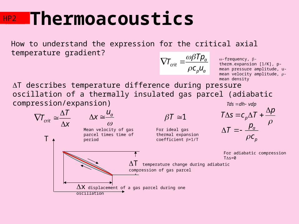
How to understand the expression for the critical axial temperature gradient?
acrit
p a
TpT
c u
-frequency, -therm.expansion [1/K], p-mean pressure amplitude, u-mean velocity amplitude, -mean density
T temperature change during adiabatic compression of gas parcel
x displacement of a gas parcel during one oscillation
T
crit
TT
x
aux
Mean velocity of gas parcel times time of period
1T
T describes temperature difference during pressure oscillation of a thermally insulated gas parcel (adiabatic compression/expansion)
For ideal gas thermal expansion coefficient =1/T
p
TcsT p
a
p
pT
c
For adiabatic compression Ts=0
vdpdhTds
Thermoacoustics - modellingTZ2HP2
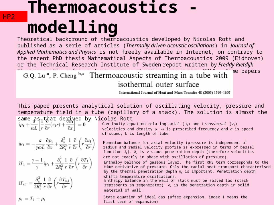
Theoretical background of thermoacoustics developed by Nicolas Rott and published as a serie of articles (Thermally driven acoustic oscillations) in Journal of Applied Mathematics and Physics is not freely available in Internet, on contrary to the recent PhD thesis Mathematical Aspects of Thermoacoustics 2009 (Eidhoven) or the Technical Research Institute of Sweden report written by Freddy Rietdijk Thermoacoustic refrigeration using a standing-wave device 2010. Some papers are available from Science direct, for example
This paper presents analytical solution of oscillating velocity, pressure and temperature field in a tube (capillary of a stack). The solution is almost the same as that derived by Nicolas Rott
Continuity equation relating axial (u1) and transversal (v1) velocities and density . is prescribed frequency and a is speed of sound, L is length of tube
Momentum balance for axial velocity (pressure is independent of radius and radial velocity profile is expressed in terms of bessel function J0). v is viscous penetration depth (therefore velocities are not exactly in phase with oscillation of pressure).
Enthalpy balance of gaseous layer. The first RHS term corresponds to the time derivative of pressure. Only the radial heat transport characterised by the thermal penetration depth t is important. Penetration depth shifts temperature oscillations.
Enthalpy balance in the wall of stack must be solved too (stack represents an regenerator). s is the penetration depth in solid material of wall.
State equation of ideal gas (after expansion, index 1 means the first term of expansion)
ThermoacousticsTZ2HP2
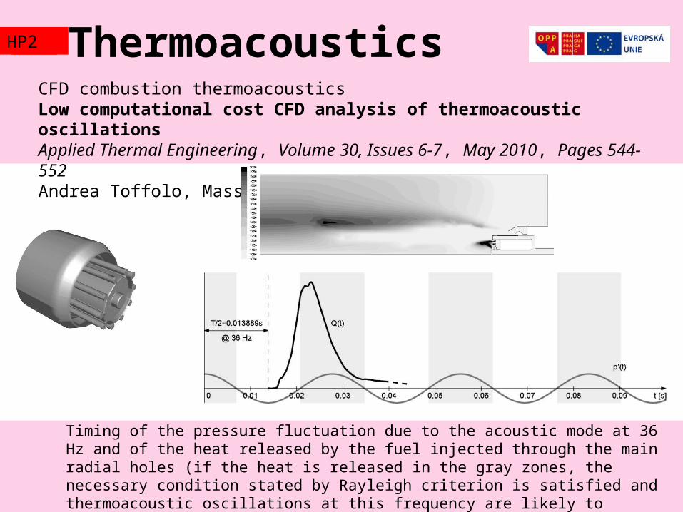
CFD combustion thermoacousticsLow computational cost CFD analysis of thermoacoustic oscillationsApplied Thermal Engineering, Volume 30, Issues 6-7, May 2010, Pages 544-552Andrea Toffolo, Massimo Masi, Andrea Lazzaretto
Timing of the pressure fluctuation due to the acoustic mode at 36 Hz and of the heat released by the fuel injected through the main radial holes (if the heat is released in the gray zones, the necessary condition stated by Rayleigh criterion is satisfied and thermoacoustic oscillations at this frequency are likely to grow).
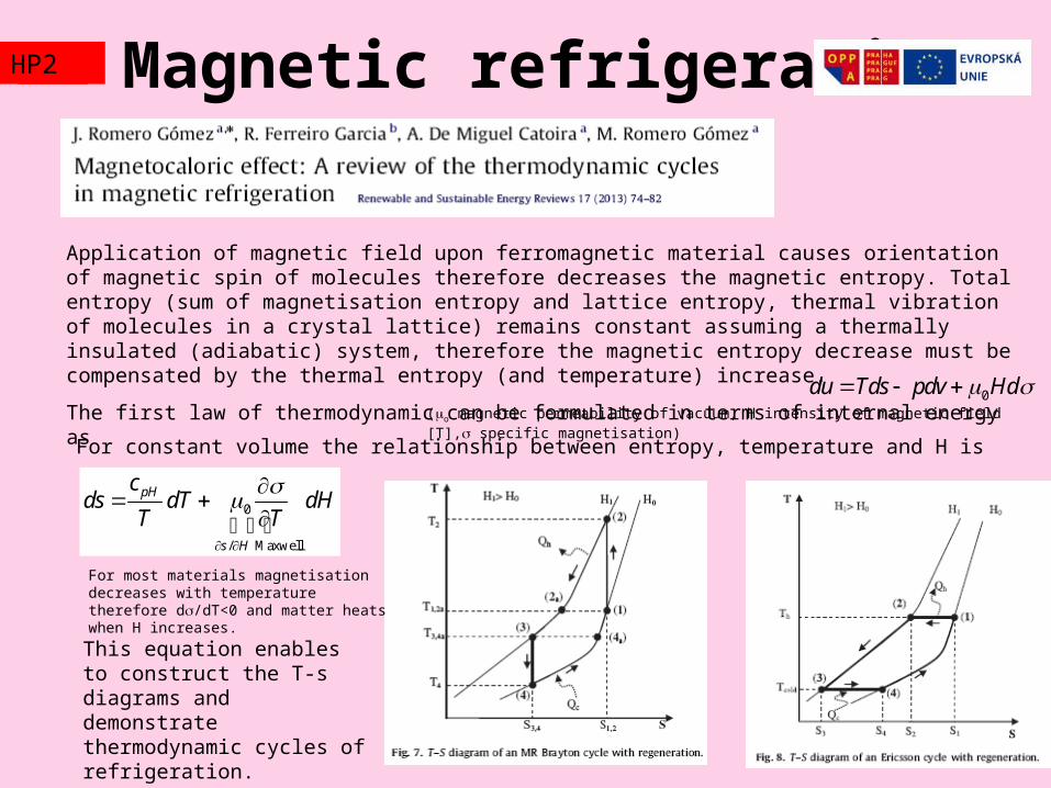
Magnetic refrigerationTZ2HP2
Application of magnetic field upon ferromagnetic material causes orientation of magnetic spin of molecules therefore decreases the magnetic entropy. Total entropy (sum of magnetisation entropy and lattice entropy, thermal vibration of molecules in a crystal lattice) remains constant assuming a thermally insulated (adiabatic) system, therefore the magnetic entropy decrease must be compensated by the thermal entropy (and temperature) increase.
The first law of thermodynamic can be formulated in terms of internal energy as 0du Tds pdv Hd (o magnetic permeability of vacuum, H intensity of magnetic field [T], specific magnetisation)
For constant volume the relationship between entropy, temperature and H is
0
/ Maxwell
pH
s H
cds dT dH
T T
This equation enables to construct the T-s diagrams and demonstrate thermodynamic cycles of refrigeration.
For most materials magnetisation decreases with temperature therefore d/dT<0 and matter heats when H increases.
Magnetic refrigerationTZ2HP2
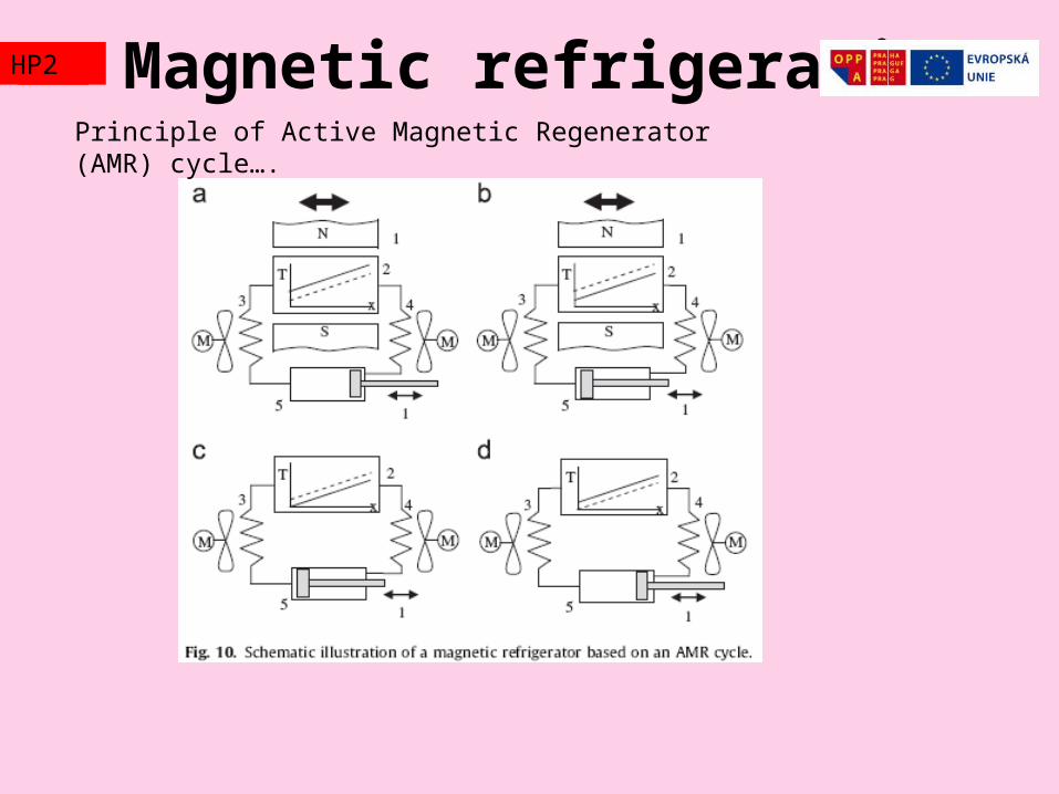
Principle of Active Magnetic Regenerator (AMR) cycle….
Magnetic refrigerationTZ2HP2
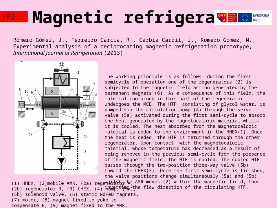
(1) HHEX, (2)mobile AMR, (2a) regenerator A, (2b) regenerator B, (3) CHEX, (4) pump, (5a), (5b) solenoid valve, (6) static NdFeB magnets, (7) motor, (8) magnet fixed to yoke to compensate F, (9) magnet fixed to the AMR, (10) AMR displacement guide
Romero Gómez, J., Ferreiro Garcia, R., Carbia Carril, J., Romero Gómez, M., Experimental analysis of a reciprocating magnetic refrigeration prototype, International Journal of Refrigeration (2013)
The working principle is as follows: during the first semicycle of operation one of the regenerators (2) is subjected to the magnetic field action generated by the permanent magnets (6). As a consequence of this field, the material contained in this part of the regenerator undergoes the MCE. The HTF, consisting of glycol water, is pumped via the circulation pump (4) through the servo-valve (5a) activated during the first semi-cycle to absorb the heat generated by the magnetocaloric material whilst it is cooled. The heat absorbed from the magnetocaloric material is ceded to the environment in the HHEX(1). Once the heat is ceded, the HTF is returned through the other regenerator. Upon contact with the magnetocaloric material, whose temperature has decreased as a result of being removed in the previous semi-cycle from the presence of the magnetic field, the HTF is cooled. The cooled HTF passes through the two-position three-way valve (5b) toward the CHEX(3). Once the first semi-cycle is finished, the valve positions change simultaneously (5a) and (5b) whilst the AMR moves (2) within the magnetic field, thus inverting the flow direction of the circulating HTF.
Magnetic refrigerationTZ2HP2
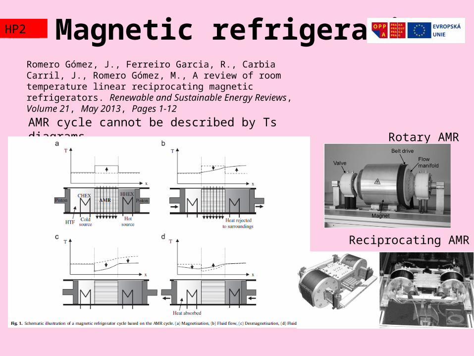
Romero Gómez, J., Ferreiro Garcia, R., Carbia Carril, J., Romero Gómez, M., A review of room temperature linear reciprocating magnetic refrigerators. Renewable and Sustainable Energy Reviews, Volume 21, May 2013, Pages 1-12
AMR cycle cannot be described by Ts diagrams.Rotary AMR
Reciprocating AMR
Magnetic refrigerationTZ2HP2
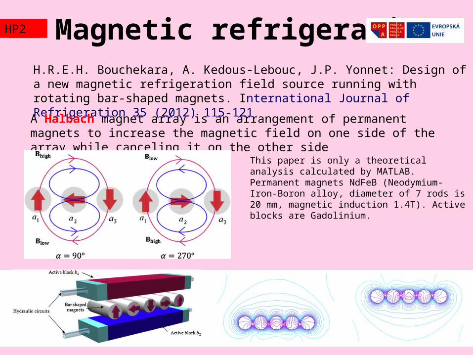
H.R.E.H. Bouchekara, A. Kedous-Lebouc, J.P. Yonnet: Design of a new magnetic refrigeration field source running with rotating bar-shaped magnets. International Journal of Refrigeration 35 (2012) 115-121
A Halbach magnet array is an arrangement of permanent magnets to increase the magnetic field on one side of the array while canceling it on the other side
This paper is only a theoretical analysis calculated by MATLAB. Permanent magnets NdFeB (Neodymium-Iron-Boron alloy, diameter of 7 rods is 20 mm, magnetic induction 1.4T). Active blocks are Gadolinium.
Laser coolingTZ2HP2
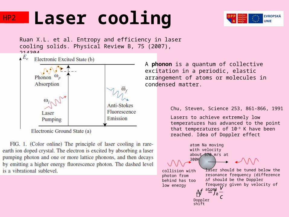
Ruan X.L. et al. Entropy and efficiency in laser cooling solids. Physical Review B, 75 (2007), 214304
A phonon is a quantum of collective excitation in a periodic, elastic arrangement of atoms or molecules in condensed matter.
Chu, Steven, Science 253, 861-866, 1991
Lasers to achieve extremely low temperatures has advanced to the point that temperatures of 10-9 K have been reached. Idea of Doppler effect
atom Na moving with velocity about 570 m/s at 300K
laser should be tuned below the resonance frequency (difference f should be the Doppler frequency given by velocity of atom)
c
vff 0
shiftDoppler
collision with photon from behind has too low energy
EXAMHP2
Thermodynamic cycles. Heat pumps and Heat engines
EXAMHP2
s
T
1
2 3
4
s
T
1
2
3
4
s
T
12
3
4
Carnot
Clausius Rankine
Ericsson
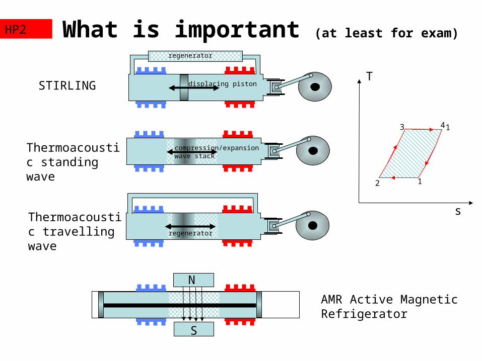
What is important (at least for exam)HP2
STIRLING
Thermoacoustic standing wave
Thermoacoustic travelling wave
N
S
regenerator
displacing piston
compression/expansion wave stack
regenerator
AMR Active Magnetic Refrigerator
13
2 1
4
T
s