Embed Size (px)
Citation preview

LECTURE NOTES
THERMODYNAMICS (AME003)
B.TECH - SEMESTER-III
PREPARED
BY
Mrs. N SANTHISREE
ASSISTANT PROFESSOR
DEPARTMENT OF MECHANICAL ENGINEERING
INSTITUTE OF AERONAUTICAL ENGINEERING
(Autonomous)
Dundigal, Hyderabad - 500 043

UNIT I
INTRODUCTION
THERMODYNAMICS
Thermodynamics is the science that deals with heat and work and those properties of substance
that bear a relation to heat and work.
Thermodynamics is the study of the patterns of energy change. Most of this course will be
concerned with understanding the patterns of energy change.
More specifically, thermodynamics deals with (a) energy conversion and (b) the direction of
change.
Basis of thermodynamics is experimental observation. In that sense it is an empirical science. The
principles of thermodynamics are summarized in the form of four laws known as zeroth, first,
second, and the third laws of thermodynamics.
The zeroth law of thermodynamics deals with thermal equilibrium and provides a means of
measuring temperature.
The first law of thermodynamics deals with the conservation of energy and introduces the concept
of internal energy.
The second law of thermodynamics dictates the limits on the conversion of heat into work and
provides the yard stick to measure the performance of various processes. It also tells whether a
particular process is feasible or not and specifies the direction in which a process will proceed. As
a consequence it also introduces the concept of entropy.
The third law defines the absolute zero of entropy.
Macroscopic and Microscopic Approaches:
Microscopic approach uses the statistical considerations and probability theory, where we deal
with “average” for all particles under consideration. This is the approach used in the disciplines
known as kinetic theory and statistical mechanics.
In the macroscopic point of view, of classical thermodynamics, one is concerned with the time-
averaged influence of many molecules that can be perceived by the senses and measured by the
instruments.
The pressure exerted by a gas is an example of this. It results from the change in momentum of
the molecules, as they collide with the wall. Here we are not concerned with the actions of
individual molecules but with the time-averaged force on a given area that can be measured by a
pressure gage.
From the macroscopic point of view, we are always concerned with volumes that are very large
compared to molecular dimensions, and therefore a system (to be defined next) contains many
molecules, and this is called continuum.
The concept of continuum loses validity when the mean free path of molecules approaches the
order of typical system dimensions.
System:
We introduce boundaries in our study called the system and surroundings.
The boundaries are set up in a way most conducive to understanding the energetics of what we're
studying.
Defining the system and surroundings is arbitrary, but it becomes important when we consider
the exchange of energy between the system and surroundings.
Two types of exchange can occur between system and surroundings: (1) energy exchange (heat,
work, friction, radiation, etc.) and (2) matter exchange (movement of molecules across the
boundary of the system and surroundings).
Based on the types of exchange which take place or don't take place, we will define three types
of systems:
isolated systems: no exchange of matter or energy
closed systems: no exchange of matter but some exchange of energy
open systems: exchange of both matter and energy
Control Volume
Control volume is defined as a volume which encloses the matter and the device inside a
control surface.
Everything external to the control volume is the surroundings with the separation given
by the control surface.
The surface may be open or closed to mass flows and it may have flows from energy in
terms of heat transfer and work across it.
The boundaries may be moveable or stationary.
In the case of a control surface that is closed to the mass flow, so that no mass can enter
or escape the control volume, it is called a control mass containing same amount of
matter at all times.
Property
In thermodynamics a property is any characteristic of a system that is associated with the
energy and can be quantitatively evaluated.
The property of a system should have a definite value when the system is in a particular
state.
Thermodynamic property is a point function.
Properties like volume of a system that depend on the mass of a system are called
extensive properties.
Properties like pressure or temperature which do not depend on the system mass are
called intensive properties.
The ratio of extensive property to the mass of the system are called specific properties
and therefore become intensive properties.
Substance can be found in three states of physical aggregation namely, solid, liquid and
vapor which are called its phases.
If the system consists of mixture of different phases, the phases are separated from each
other by phase boundary.
The thermodynamic properties change abruptly at the phase boundary, even though the
intensive properties like temperature and pressure are identical.
Equilibrium
When the property of a system is defined, it is understood that the system is in
equilibrium.
If a system is in thermal equilibrium, the temperature will be same throughout the system.
If a system is in mechanical equilibrium, there is no tendency for the pressure to change.
In a single phase system, if the concentration is uniform and there is no tendency for
mass transfer or diffusion, the system is said to be in chemical equilibrium.
A system which is simultaneously in thermal, mechanical, and chemical equilibrium is
said to be in thermal equilibrium.
Process
A process is path followed by a system in reaching a given final state of equilibrium state starting
from a specified initial state.
An actual process occurs only when the equilibrium state does not exist.
An ideal process can be defined in which the deviation from thermodynamic equilibrium is
infinitesimal.
All the states the system passes through during a quasi-equilibrium process may be considered
equilibrium states.
For non-equilibrium processes, we are limited to a description of the system before the process
occurs and after the equilibrium is restored.
Several processes are described by the fact that one property remains constant.
The prefix iso- is used to describe such processes.
A process is said to be reversible if both the system and its surroundings can be restored to their
respective initial states by reversing the direction of the process.
Reversible: if the process happens slow enough to be reversed.
Irreversible: if the process cannot be reversed (like most processes).
The main processes are
Isobaric: process done at constant pressure
Isochoric: process done at constant volume
Isothermal: process done at constant temperature
Adiabatic: process where q=0
Cyclic: process where initial state = final state

Internal Energy
The molecule as a whole can move in x, y and z directions with respective components
of velocities and hence possesses kinetic energy.
There can be rotation of molecule about its center of mass and than the kinetic energy
associated with rotation is called rotational energy.
In addition the bond length undergoes change and the energy associated with it is called
vibrational energy.
The electron move around the nucleus and they possess a certain energy that is called
electron energy.
The microscopic modes of energy are due to the internal structure of the matter and
hence sum of all microscopic modes of energy is called the internal energy.
Bulk kinetic energy (KE) and potential energy (PE) are considered separately and the other
energy of control mass as a single property (U).
The total energy possessed by the body is given by:
E = KE + PE + U
Work
Whenever a system interacts with its surroundings, it can exchange energy in two ways- work
and heat.
In mechanics, work is defined as the product of the force and the displacement in the direction of
the force.Work done when a spring is compressed or extended: According to Hooke's law
Spring force = - k (x – x0)
Where k is the spring constant, x0 is the equilibrium position, and x is the final position. The
negative sign shows that the direction of the spring force is opposite the direction of the
displacement from x0. The external force is equal in magnitude but opposite in sign to the spring
force, so External force (force of your hands) = k (x –x0).
Now, we want to calculate the work done when we stretch the spring from position 1 to position
2.
W = F dx = k (x – x0) d(x-x0) = 1/2 k [(x2-x0)2 - (x1-x0)
2]
Work done when a volume is increased or decreased
Consider a gas in a container with a movable piston on top. If the gas expands, the piston moves
out and work is done by the system on the surroundings. Alternatively, if the gas inside contracts,
the piston moves in and work is done by the surroundings on the system. Why would the gas
inside contract or expand?
It would if the external pressure, Pex, and the internal pressure, Pin, were different. To calculate
the work done in moving the piston, we know that the force = pressure times area and then work
equals pressure times area times distance or work equals pressure times the change in volume. So,
W = the integral of (Pex) dV
The differential work done (dW) associated with a differential displacement (dl) is given by
dW = F dl
For a piston cylinder assembly,
dW = F dl = PA (dl) = P dV

If the gas is allowed to expand reversibly from the initial pressure P to final pressure P, then the
work done is given by
W = ∫ p dV
The integral represents the area under the curve on a pressure versus volume diagram.
Therefore the work depends on the path followed and work is a path function and hence
not a property of the system.
The above expression does not represent work in the case of an irreversible process.
The thermodynamic definition of work is “ Work is said to be done by a system on the
surrounding if the sole effect external to the system could be reduced to the raising of a
mass through a distance”.
Heat
Heat like work, is a form of energy.
The energy transfer between a system and its surroundings is called heat if it occurs by virtue of
the temperature difference across the boundary.
The two modes of energy transfer – work and heat- depend on the choice of the system.
Heat energy moves from a hotter body to a colder body upon contact of the two bodies.
If two bodies at different temperatures are allowed to remain in contact, the system of two bodies
will eventually reach a thermal equilibrium (they will have the same temperature).
A body never contains heat. Rather heat is a transient phenomenon and can be identified as it
crosses the boundary.
The State Postulate
The state of the system is described by its properties.
Once a sufficient number of properties are specified, the rest of the properties assume some
values automatically.
The number of properties required to fix a state of a system is given by the state postulate:
The state of a simple compressible system is completely specified by two independent, intensive
properties.
The system is called a simple compressible system in the absence of electrical, magnetic,
gravitational, motion, and surface tension effects.
The state postulate requires that the two properties specified be independent to fix the state.
Two properties are independent if one property can be varied while the other one is held constant.
Temperature and specific volume, for example, are always independent properties, and together
they can fix the state of a simple compressible system.

Thus, temperature and pressure are not sufficient to fix the state of a two-phase system.
Otherwise an additional property needs to be specified for each effect that is significant.
An additional property needs to be specified for each other effect that is significant.
Zeroth Law of Thermodynamics
We cannot assign numerical values to temperatures based on our sensations alone. Furthermore,
our senses may be misleading.
Several properties of material changes with temperature in a repeatable and predictable way, and
this forms the basis of accurate temperature measurement.
The commonly used mercury-in-glass thermometer for example, is based on the expansion of
mercury with temperature.
Temperature is also measured by using several other temperature dependant properties.
Two bodies (eg. Two copper blocks) in contact attain thermal equilibrium when the heat transfer
between them stops.
The equality of temperature is the only requirement for thermal equilibrium.
The Zeroth Law of Thermodynamics
If two bodies are in thermal equilibrium with a third body, they are also in thermal
equilibrium with each other.
This obvious fact cannot be concluded from the other laws of thermodynamics, and it serves as a
basis of temperature measurement.
By replacing the third body with a thermometer, the zeroth law can be restated two bodies are in
thermal equilibrium if both have the same temperature reading even if they are not in contact
The zeroth law was first formulated and labeled by R.H. Fowler in 1931.
Temperature Scales
All temperature scales are based on some easily reproducible states such as the freezing and
boiling point of water, which are also called the ice-point and the steam-point respectively.
A mixture of ice and water that is in equilibrium with air saturated with water vapour at 1atm
pressure is said to be at the ice-point, and a mixture of liquid water and water vapour (with no air)
in equilibrium at 1atm is said to be at the steam-point.
Celsius and Fahrenheit scales are based on these two points (although the value assigned to these
two values is different) and are referred as two-point scales.
In thermodynamics, it is very desirable to have a temperature scale that is independent of the
properties of the substance or substances.
Such a temperature scale is called a thermodynamic temperature scale.(Kelvin in SI)
Ideal gas temperature scale
The temperatures on this scale are measured using a constant volume thermometer.
Based on the principle that at low pressure, the temperature of the gas is proportional to its
pressure at constant volume.
The relationship between the temperature and pressure of the gas in the vessel can be expressed
as T = a + b.P
Where the values of the constants a and b for a gas thermometer are determined experimentally.
Once a and b are known, the temperature of a medium can be calculated from the relation above
by immersing the rigid vessel of the gas thermometer into the medium and measuring the gas
pressure.
Ideal gas temperature scale can be developed by measuring the pressures of the gas in the vessel
at two reproducible points (such as the ice and steam points) and assigning suitable values to
temperatures those two points.
Considering that only one straight line passes through two fixed points on a plane, these two
measurements are sufficient to determine the constants a and b in the above equation.
If the ice and the steam points are assigned the values 0 and 100 respectively, then the gas
temperature scale will be identical to the Celsius scale.
In this case, the value of the constant a (that corresponds to an absolute pressure of zero) is
determined to be –273.150C when extrapolated.
The equation reduces to T = bP, and thus we need to specify the temperature at only one point to
define an absolute gas temperature scale.
Absolute gas temperature is identical to thermodynamic temperature in the temperature range in
which the gas thermometer can be used.
We can view that thermodynamic temperature scale at this point as an absolute gas temperature
scale that utilizes an ideal gas that always acts as a low-pressure gas regardless of the
temperature.
At the Tenth international conference on weights and measures in 1954, the Celsius scale has
been redefined in terms of a single fixed point and the absolute temperature scale.
The triple point occurs at a fixed temperature and pressure for a specified substance.
The selected single point is the triple point of water (the state in which all three phases of water
coexist in equilibrium), which is assigned the value 0.01 C. As before the boiling point of water at
1 atm. Pressure is 100.0 C. Thus the new Celsius scale is essentially the same as the old one.
On the Kelvin scale, the size of Kelvin unit is defined as “ the fraction of 1/273.16 of the
thermodynamic temperature of the triple point of water, which is assigned a value of 273.16K”.
The ice point on Celsius and Kelvin are respectively 0 and 273.15 K.

GRAPHICAL REPRESENTATION OF DATA
1. Pressure versus temperature (P-T)
2. Pressure vs. volume (P-v)
3. Temperature vs. volume (T-v)
4. Temperature vs. entropy (T-s)
5. Enthalpy vs. entropy (h-s)
6. Pressure vs. enthalpy (P-h)
First Law Analysis to Non-flow Processes
Constant Volume process:
1. Heating of gas enclosed in a rigid vessel:
dU = dQ or U2- U1 , Q = m Cv (T2 – T1)
2. Shaft work done on a system at constant volume
dU = dQ- dW = dQ – (dWpdv + dWs)
or dU = - dWs or -Ws = U2- U1
3. Constant volume process involving electrical work:
- Ws = U2- U1
For an adiabatic process the work is done is independent of path.
Constant Pressure Process
1. Reversible heating of a gas
2. Phase Change at constant pressure(Rev.)
3. Shaft work at constant pressure
4. Electrical work at constant pressure
W = P (V2 –V1)
dU = dQ-dW = dQ- PdV = dQ- d(PV)
or, dQ = dU + d(PV) = d(U+ PV) = dH

Q = H the heat interaction is equal to increase in enthalpy
Constant Temperature Process
dU = dQ-dW = dQ- PdV
for an ideal gas u= u(T) then dU = 0
dQ = PdV = RT (dv/v)
Q = W = RT ln (v2/ v1)
Reversible Adiabatic Process
dU = -dW or W = -U
This equation is true for reversible as well as irreversible process.
Cv dT = -Pdv = -RT/v dv
dT/T = -R/Cv dv/v
R/Cv = - 1
dT/T = -(-1) dv/v
T2/T1 = (v1/v2) (-1)
Tv(-1)
= constant
Also Pv = Constant using perfect gas relation
FIRST LAW OF THERMODYNAMICS
The first law of thermodynamics is the thermodynamic expression of the conservation of energy.
This law most simply stated by saying that “energy can not be created or destroyed” or that “the
energy of the universe is constant”.
This law can be stated for a system (control mass) undergoing a cycle or for a change of state of a
system.
Stated for a system undergoing a cycle, the cyclic integral of the work is proportional to the cyclic
integral of the heat.
Mathematically stated, for a control mass undergoing a cyclic process such as in Joule’s
experiment and for consistent set of units
∫dQfrom system= ∫dWon system
or ∫dQfrom system- ∫dWon system = 0
The important thing to remember is that the first law states that the energy is conserved always.
Sign convention The work done by a system on the surroundings is treated as a positive quantity.
Similarly, energy transfer as heat to the system from the surroundings is assigned a positive sign.
With the sign convention one can write,
∫dQ = ∫dW
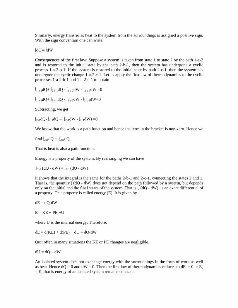
Consequences of the first law: Suppose a system is taken from state 1 to state 2 by the path 1-a-2
and is restored to the initial state by the path 2-b-1, then the system has undergone a cyclic
process 1-a-2-b-1. If the system is restored to the initial state by path 2-c-1, then the system has
undergone the cyclic change 1-a-2-c-1. Let us apply the first law of thermodynamics to the cyclic
processes 1-a-2-b-1 and 1-a-2-c-1 to obtain
∫1-a-2dQ+ ∫2-b-1dQ - ∫1-a-2dW - ∫2-b-1dW =0
∫1-a-2dQ+ ∫2-c-1dQ - ∫1-a-2dW - ∫2-c-1dW=0
Subtracting, we get
∫2b1dQ- ∫2c1dQ –( ∫2b1dW - ∫2c1dW) =0
We know that the work is a path function and hence the term in the bracket is non-zero. Hence we
find ∫2b1dQ = ∫2c1dQ
That is heat is also a path function.
Energy is a property of the system: By rearranging we can have
∫2b1 (dQ - dW) = ∫2c1 (dQ - dW)
It shows that the integral is the same for the paths 2-b-1 and 2-c-1, connecting the states 2 and 1.
That is, the quantity ∫ (dQ - dW) does not depend on the path followed by a system, but depends
only on the initial and the final states of the system. That is ∫ (dQ - dW) is an exact differential of
a property. This property is called energy (E). It is given by
dE = dQ-dW
E = KE + PE +U
where U is the internal energy. Therefore,
dE = d(KE) + d(PE) + dU = dQ-dW
Quit often in many situations the KE or PE changes are negligible.
dU = dQ – dW
An isolated system does not exchange energy with the surroundings in the form of work as well
as heat. Hence dQ = 0 and dW = 0. Then the first law of thermodynamics reduces to dE = 0 or E2
= E1 that is energy of an isolated system remains constant.
Perpetual Motion Machine of the first kind: An imaginary device which delivers work
continuously without absorbing energy from the surroundings is called a Perpetual Motion
machine of the first kind. Since the device has to deliver work continuously, it has to operate on a
cycle. If such a device does not absorb energy from its surroundings ∫dQ =0. From the first
law, it can be observed that ∫dW =0, if ∫ dQ = 0. Therefore such a device is impossible from first
law of thermodynamics.
First law analysis of non-flow processes: The first law of thermodynamics can be applied to a
system to evaluate the changes in its energy when it undergoes a change of state while interacting
with its surroundings. The processes that are usually encountered in thermodynamic analysis of
systems can be identified as any one or a combination of the following elementary processes:
Constant volume (isochoric) process
Constant pressure (isobaric) process
Constant temperature (isothermal) process.
Adiabatic process.
Constant volume process: Suppose a gas enclosed in a rigid vessel is interacting with the
surroundings and absorbs energy Q as heat. Since the vessel is rigid, the work done W due to
expansion or compression is zero. Applying the first law, we get
dU = dQ or Q = U2 –U1
That is, heat interaction is equal to the change in internal energy of the gas. If the system contains
a mass m equal of an ideal gas, then
Q = ΔU = mCv (T2 –T1)
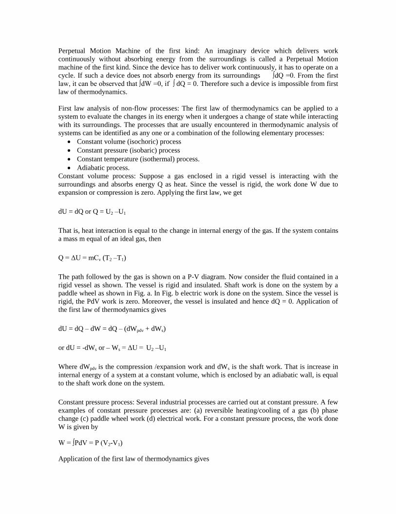
The path followed by the gas is shown on a P-V diagram. Now consider the fluid contained in a
rigid vessel as shown. The vessel is rigid and insulated. Shaft work is done on the system by a
paddle wheel as shown in Fig. a. In Fig. b electric work is done on the system. Since the vessel is
rigid, the PdV work is zero. Moreover, the vessel is insulated and hence dQ = 0. Application of
the first law of thermodynamics gives
dU = dQ – dW = dQ – (dWpdv + dWs)
or dU = -dWs or – Ws = ΔU = U2 –U1
Where dWpdv is the compression /expansion work and dWs is the shaft work. That is increase in
internal energy of a system at a constant volume, which is enclosed by an adiabatic wall, is equal
to the shaft work done on the system.
Constant pressure process: Several industrial processes are carried out at constant pressure. A few
examples of constant pressure processes are: (a) reversible heating/cooling of a gas (b) phase
change (c) paddle wheel work (d) electrical work. For a constant pressure process, the work done
W is given by
W = ∫PdV = P (V2-V1)
Application of the first law of thermodynamics gives
dU = dQ – dW = dQ – PdV = dQ – d(PV)
or dQ = dU + d(PV) = d(U + PV) = dH
or Q = ΔH
That is in a constant pressure process, the heat interaction is equal to the increase in the enthalpy
of the system. Now consider the constant pressure processes in which the system is enclosed by
an adiabatic boundary. Application of the first law gives:
dU = dQ – dW = dQ – (PdV + dWs)
Here, the net work done (dW) consists of two parts – the PdV work associated with the motion of
the boundary and (-dWs), the shaft work (or electrical work) done by the surroundings. Since the
system is enclosed by an adiabatic boundary, dQ = 0 the equation can be written as
-dWs = dU + d(PV) = dH
That is, the increase in the enthalpy of the system is equal to the shaft work done on the system.
Constant temperature process: Suppose a gas enclosed in the piston cylinder assembly is allowed
to expand from P1 to P2 while the temperature is held constant. Then application of the first law
gives:
dU = dQ – dW = dQ –PdV
It is not possible to calculate work and heat interactions unless the relationships between the
thermodynamic properties of the gas are known. Suppose the gas under consideration is an ideal
gas (which follows the relation Pv = RT and u = u(T) only) then for an isothermal process,
dU = 0 and dQ = PdV = RTdv/v or Q =W = RTln(v2/v1)
Reversible adiabatic (Isentropic process):
Polytropic Process
W = cdv/ vn
w = (P1v1- P2v2)/(n-1)
du = dq – dw
u2 – u1 = q - (P1v1- P2v2)/(n-1)
u2 – u1 = Cv (T2 – T1) = q – w
q = R(T2 – T1)/(-1) + (P1v1- P2v2)/(n-1)
= R (T1 – T2){1/(n-1) – 1/(-1)}
=(P1v1- P2v2)/(n-1) {( -n)/(-1)}
=w.{ ( -n)/(-1)}
Problem: Air (ideal gas with = 1.4) at 1 bar and 300K is compressed till the final volume is one-
sixteenth of the original volume, following a polytropic process Pv1.25
= const. Calculate (a) the
final pressure and temperature of the air, (b) the work done and (c) the energy transferred as heat
per mole of the air.
Solution: (a) P1v11.25
= P2v21.25
P2 = P1(v1/v2)1.25
= 1(16)1.25
= 32 bar
T2 = (T1P2v2)/(P1v1) = (300 x 32 x 1)/(1x16)
= 600K
(b) w = (P1v1- P2v2)/(n-1)
= Ru(T1 – T2)/(n-1)
= 8.314 (300 – 600)/(1.25-1) = -9.977 kJ/mol
(c) q = w.{ ( -n)/(-1)}
= -9.977 (1.4 – 1.25)/(1.4-1)
= -3.742 kJ/mol
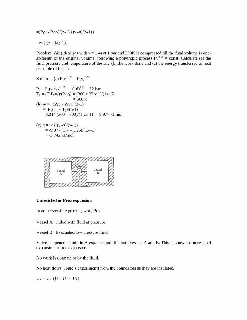
Unresisted or Free expansion
In an irreversible process, w Pdv
Vessel A: Filled with fluid at pressure
Vessel B: Evacuated/low pressure fluid
Valve is opened: Fluid in A expands and fills both vessels A and B. This is known as unresisted
expansion or free expansion.
No work is done on or by the fluid.
No heat flows (Joule’s experiment) from the boundaries as they are insulated.
U2 = U1 (U = UA + UB)
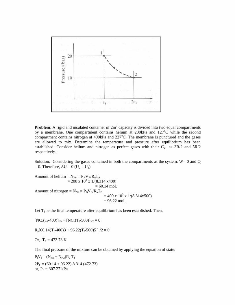
Problem: A rigid and insulated container of 2m3 capacity is divided into two equal compartments
by a membrane. One compartment contains helium at 200kPa and 127oC while the second
compartment contains nitrogen at 400kPa and 227oC. The membrane is punctured and the gases
are allowed to mix. Determine the temperature and pressure after equilibrium has been
established. Consider helium and nitrogen as perfect gases with their Cv as 3R/2 and 5R/2
respectively.
Solution: Considering the gases contained in both the compartments as the system, W= 0 and Q
= 0. Therefore, U = 0 (U2 = U1)
Amount of helium = NHe = PAVA/RuTA
= 200 x 103 x 1/(8.314 x400)
= 60.14 mol.
Amount of nitrogen = NN2 = PBVB/RuTB
= 400 x 103 x 1/(8.314x500)
= 96.22 mol.
Let Tf be the final temperature after equilibrium has been established. Then,
[NCv(Tf-400)]He + [NCv(Tf-500)]N2 = 0
Ru[60.14(Tf-400)3 + 96.22(Tf-500)5 ] /2 = 0
Or, Tf = 472.73 K
The final pressure of the mixture can be obtained by applying the equation of state:
PfVf = (NHe + NN2)Ru Tf
2Pf = (60.14 + 96.22) 8.314 (472.73)
or, Pf = 307.27 kPa

Control-Volume Analysis
Control volume is a volume in space of special interest for particular analysis.
The surface of the control volume is referred as a control surface and is a closed surface.
The surface is defined with relative to a coordinate system that may be fixed, moving or rotating.
Mass, heat and work can cross the control surface and mass and properties can change with time
within the control volume.
Examples: turbines, compressors, nozzle, diffuser, pumps, heat exchanger, reactors, a thrust-
producing device, and combinations of these.
First law of thermodynamics for a continuous system
Let the continuous system be in state 1 at time t and after a differential time dt, let it be in the
state 2. The change in the energy of the continuous system is,
Now,
dE = dQ – dW
or,
First law of thermodynamics to a control volume
Or
[Rate of accumulation of mass inside the control volume] = [Rate of mass entering the control
volume at inlet] – [Rate of mass leaving the control volume at exit]
The above is commonly known as continuity equation.
We should identify a definite quantity of matter which remains constant as the matter flows. For
this purpose, let the boundary of the system include all matter inside the control volume and that
which is about to enter the control volume during the differential time interval dt.
dtdt
edVddE
][
WQdt
dE
V
WQedVdt
d
eidt
dmmm

At time t, the system is defined as the mass contained in the control volume and the mass in
region A which is about to enter the control volume in a differential time dt.
At time t+dt, the system is defined as the mass contained in the control volume and the mass in
region B.
Therefore, during the differential time dt, the system configuration undergoes a change.
Mass contained in region A = im
dt
Mass contained in region B = em
dt
From mass balance,
The work done as the mass enters the control
volume = -Pivi im
dt
The work done by mass exiting the control volume =
Peve em
dt
Energy of the system at time t = E(t) +im
eidt
Energy of the system at time (t+dt) =
E(t+dt) + ee em
dt
Energy transferred as heat to the system = Q
dt
Shaft work done by the system = shW
dt
From the first law,
em
dt] – [E(t) +im
eidt ] = Q
dt - shW
dt – ( Peve em
-Pivi im
[E(t+dt) + ee
)dt
em
( ee + Peve)- im
(ei + Pivi)= Q
- shW
-
or,
em
(he+Ve2/2 + gZe) - im
(hi+Vi2/2 + gZi) = Q
- shW
- dE/dt
where, he = ue + Peve, hi = ui + Pivi
Or, Rate of energy accumulation = rate of energy inflow – rate of energy outflow
dtm )(dtm )( ei
dttmtm
dt
tEdttE )()(
em

Steady state flow process
Assumptions:
= =
The state of matter at the inlet, exit and at any given point inside the
control volume does not change with respect to time.
dE / dt = 0
The rate of energy transfers across the control surface is constant.
+ gZe) - (hi+Vi2/2 + gZi) =( Q
- shW
)/ (he+Ve2/2
Steady state steady flow process
For negligible change in kinetic and potential energies through the control volume,
If the control volume is well insulated (i.e. adiabatic), then, q = 0.
em
im
m
m
mWmQ shwandqwhere
ZZgVV
hhPeKehwq ie
ie
ie
//,
)(2
22
)/( kgkJhwq

For steady flow devices, such as turbines, compressors and pumps, shW
is power transmitted
through a shaft.
The unit of ke is m2/s
2 which is equivalent to Joule/kg. The enthalpy is usually given in
kJ/kg. So kinetic energy should be expressed in kJ/kg. This is accomplished by dividing it by
1000.
Kinetic energy term at low velocities is negligible, but should be accounted for at high velocities.
By similar argument, the elevation difference between inlet and exit of most industrial devices
such as compressors and turbines is small and potential energy term is negligible (particularly for
gases). The only time the potential energy term is significant is when a process involves pumping
a fluid to high elevations.
Turbine
A turbine is a rotary steady state steady flow machine whose purpose is the production of shaft
power at the expense of the pressure of the working fluid.
Two general classes of turbines are steam and gas turbines depending on the working substance
used.
Usually, changes in potential energy are negligible, as is the inlet kinetic energy. Often the exit
kinetic energy is neglected (if in a problem, the flow velocities are specified, the kinetic energy
term should be included).
Normally, the process in the turbine is adiabatic and the work output reduces to decrease in
enthalpy from the inlet to exit states.
Compressor / pump
The purpose of a compressor (gas) or pump (liquid) is the same, to increase the pressure of a fluid
by putting in shaft work (power). There are two fundamentally different types of compressors:
1. The rotary type (either axial or centrifugal flow)
2. A piston/cylinder type compressor.
The first type is analyzed using control volume approach (steady state steady flow process). The
working fluid enters the compressor at low pressure and exits at high pressure.
Usually, changes in potential energy are negligible as is the inlet kinetic energy. Often, exit
kinetic energy is neglected as well (wherever, in a problem, velocities are specified, ke term
should not be neglected).
The compression process is usually adiabatic.
2/)( 22
ie VVKe
)( ei hhsh mW
]2/)()[( 22
eiei VVhhsh mW
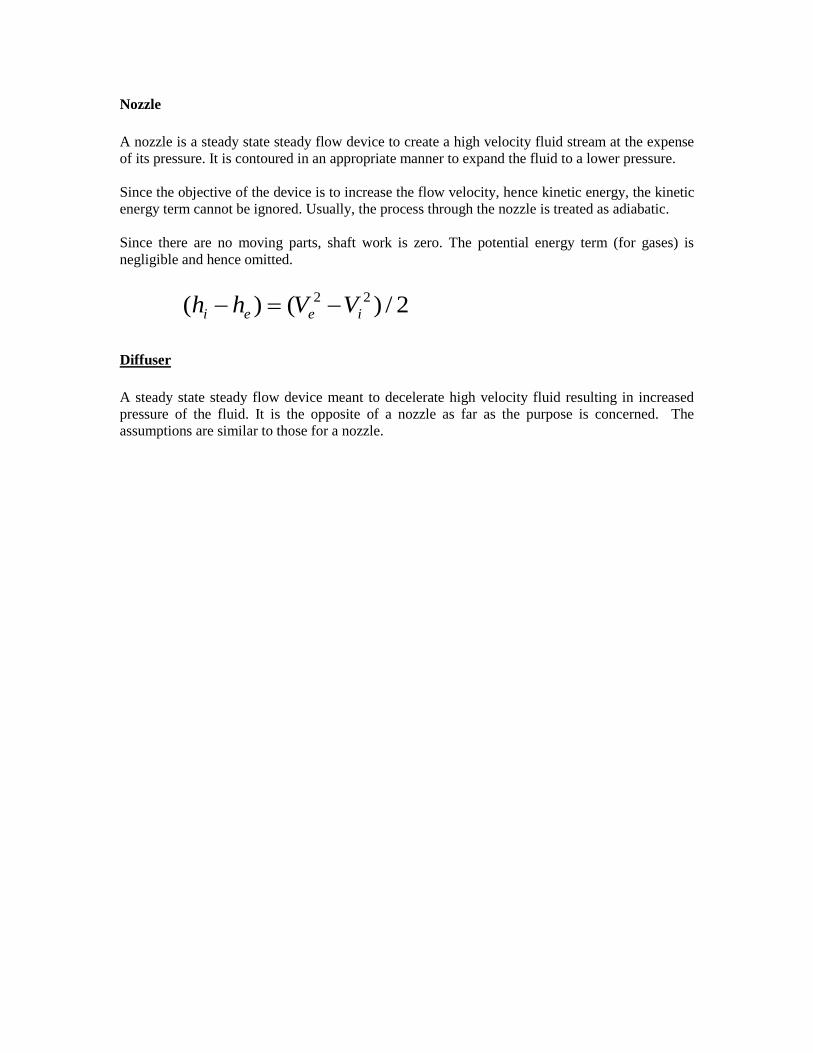
Nozzle
A nozzle is a steady state steady flow device to create a high velocity fluid stream at the expense
of its pressure. It is contoured in an appropriate manner to expand the fluid to a lower pressure.
Since the objective of the device is to increase the flow velocity, hence kinetic energy, the kinetic
energy term cannot be ignored. Usually, the process through the nozzle is treated as adiabatic.
Since there are no moving parts, shaft work is zero. The potential energy term (for gases) is
negligible and hence omitted.
Diffuser
A steady state steady flow device meant to decelerate high velocity fluid resulting in increased
pressure of the fluid. It is the opposite of a nozzle as far as the purpose is concerned. The
assumptions are similar to those for a nozzle.
2/)()( 22
ieei VVhh

UNIT II
LIMITATIONS OF FIRST LAW
First law is a statement of conservation of energy principle. Satisfaction of first law alone does
not ensure that the process will actually take place.
Examples:
1. A cup of hot coffee left in a cooler room eventually cools off. The reverse of this
process- coffee getting hotter as a result of heat transfer from a cooler room does not
take place.
2. Consider heating of a room by passage of electric current through an electric resistor.
Transferring of heat from room will not cause electrical energy to be generated through
the wire.
3. Consider a paddle-wheel mechanism operated by fall of mass. Potential energy of mass
decreases and internal energy of the fluid increases. Reverse process does not happen,
although this would not violate first law.
4. Water flows down hill where by potential energy is converted into K.E. Reverse of this
process does not occur in nature.
Conclusion:
Processes proceed in a certain direction and not in the reverse direction. The first law places no
restriction on direction.
A process will not occur unless it satisfies both the first and second laws of thermodynamics.
Second law not only identifies the direction of process, it also asserts that energy has quality as
well as quantity.
Thermal Reservoir
A thermal reservoir is a large system (very high mass x specific heat value) from which a quantity
of energy can be absorbed or added as heat without changing its temperature. The atmosphere and
sea are examples of thermal reservoirs.
Any physical body whose thermal energy capacity is large relative to the amount of energy it
supplies or absorbs can be modeled as a thermal reservoir.
A reservoir that supplies energy in the form of heat is called a source and one that absorbs energy
in the form of heat is called a sink.
Heat Engine
It is a cyclically operating device which absorbs energy as heat from a high temperature reservoir,
converts part of the energy into work and rejects the rest of the energy as heat to a thermal
reservoir at low temperature.
The working fluid is a substance, which absorbs energy as heat from a source, and rejects energy
as heat to a sink.
Thermal Power Plant

Working Fluid ------- Water
Q1 – Heat received from hot gases
WT – Shaft work by turbine
Q2 – Heat rejected to cooling water in condenser
WP – Work done on the pump
Wnet=WT-WP
W = Q1 – Q2
Thermal Efficiency,
1
21
11 Q
Q
W
Q
Wnet
Schematic representation of Heat Engine
Schematic representation of Refrigerator and Heat pump.

QL – Heat absorbed from low temperature thermal reservoir
QH – Heat rejected to a high temperature thermal reservoir when work (W) is done on it.
LH
HH
HP
LH
LL
R
Q
W
QCOP
Q
W
QCOP
)(
)(
In a reversible, isothermal expansion of an ideal gas, all the energy absorbed as heat by the
system is converted completely into work. However this cannot produce work continuously (not a
cycle).
Single reservoir heat engine (1 T engine) is not possible.
Second Law of Thermodynamics
Kelvin-Planck Statement: - It is impossible to devise a cyclically operating device, which
produces no other effect than the extraction of heat from a single thermal reservoir and delivers
an equivalent amount of work.
Heat engine with single thermal reservoir is not possible.
For a 1-T engine the thermal efficiency =W/Q=1. No heat engine can have efficiency equal to
unity.
Clausius Statement: - It is impossible to construct a device that operates in a cycle and produces
no effect other than the transfer of heat from a lower-temperature body to higher-temperature
body.
Equivalence of the two statements

To prove that violation of the Kelvin-Planck Statement leads to a violation of the Clausius
Statement, let us assume that Kelvin-Planck statement is incorrect.
Consider a cyclically working device 1, which absorbs energy Q1 as heat from a thermal reservoir
at TH. Equivalent amount of work W(W=Q1) is performed.
Consider another device 2 operating as a cycle, which absorbs energy QL as heat from a low
temperature thermal reservoir at TL and rejects energy QH (QH=QL+W). Such a device does not
violate Clausius statement.
If the two devices are now combined, the combined device (enclosed by the dotted boundary)
transfers heat QL from the low temperature reservoir at TL to a high temperature reservoir at TH
with out receiving any aid from an external agent, which is the violation of the Clausius
statement.
Likewise let us assume that the Clausius statement is incorrect. So we have a device 1, cyclically
working transferring heat Q from a low temperature reservoir at TL to a high temperature thermal
reservoir at TH . Consider another device 2, which absorbs heat Q1 from a high temperature
reservoir at TH does work W and rejects energy Q as heat tot the low temperature reservoir at TL
as shown in figure.
If the two devices are combined (shown in figure by a dotted enclosure), then the combined
device receives energy (Q1-Q) as heat from a thermal reservoir and delivers equivalent work
(W=Q1-Q) in violation of the Kelvin-Planck statement.
Therefore violation of Clausius statement leads to the violation of the Kelvin-Planck statement.
Hence, these two statements are equivalent.
Perpetual Motion Machines
A device that violates the First law of thermodynamics (by creating energy) is called a Perpetual
Motion Machine of the first kind.
A device that violates the Second law of thermodynamics is called a Perpetual Motion Machine
of the Second kind.
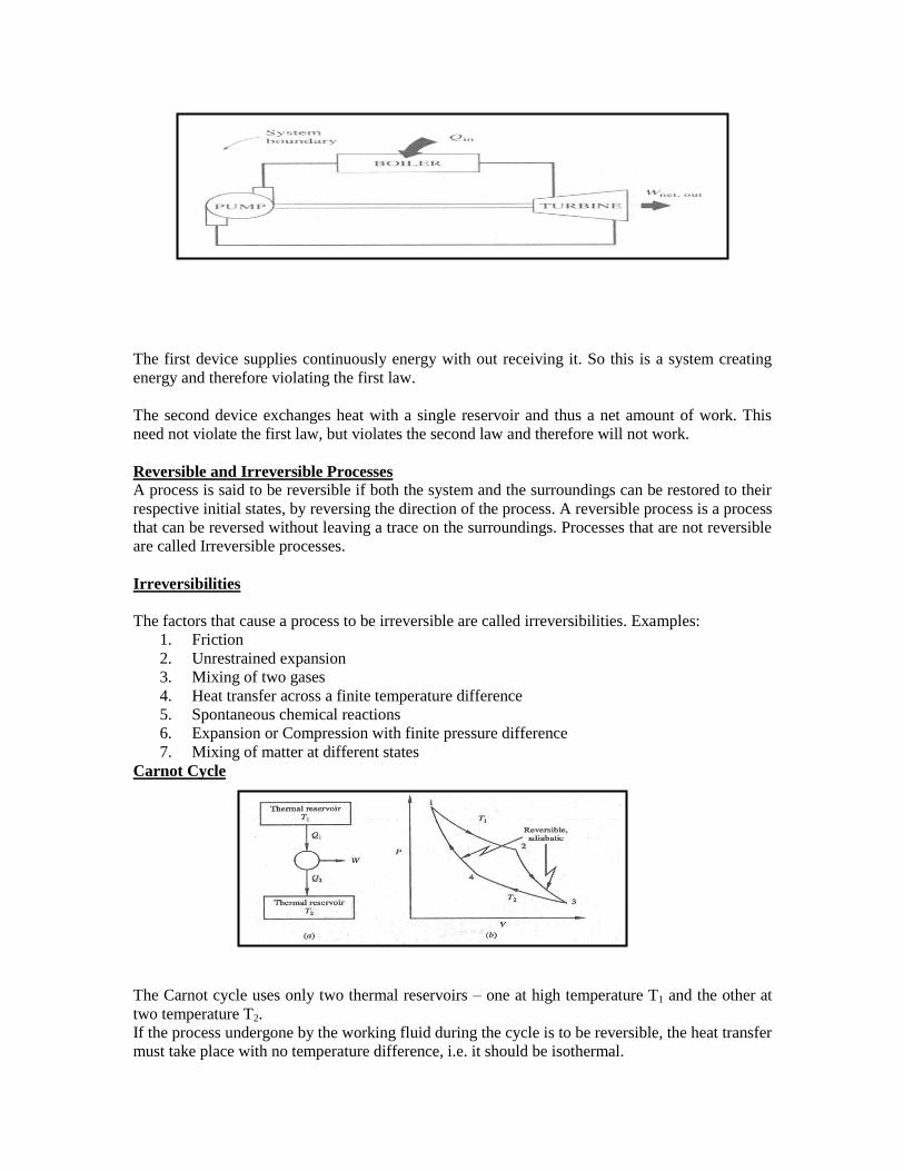
The first device supplies continuously energy with out receiving it. So this is a system creating
energy and therefore violating the first law.
The second device exchanges heat with a single reservoir and thus a net amount of work. This
need not violate the first law, but violates the second law and therefore will not work.
Reversible and Irreversible Processes
A process is said to be reversible if both the system and the surroundings can be restored to their
respective initial states, by reversing the direction of the process. A reversible process is a process
that can be reversed without leaving a trace on the surroundings. Processes that are not reversible
are called Irreversible processes.
Irreversibilities
The factors that cause a process to be irreversible are called irreversibilities. Examples:
1. Friction
2. Unrestrained expansion
3. Mixing of two gases
4. Heat transfer across a finite temperature difference
5. Spontaneous chemical reactions
6. Expansion or Compression with finite pressure difference
7. Mixing of matter at different states
Carnot Cycle
The Carnot cycle uses only two thermal reservoirs – one at high temperature T1 and the other at
two temperature T2.
If the process undergone by the working fluid during the cycle is to be reversible, the heat transfer
must take place with no temperature difference, i.e. it should be isothermal.
The Carnot cycle consists of a reversible isothermal expansion from state 1 to 2, reversible
adiabatic expansion from state 2 to 3, a reversible isothermal compression from state 3 to 4
followed by a reversible adiabatic compression to state 1.
The thermal efficiency, is given by
= Net work done / Energy absorbed as heat
During processes 2-3 and 4-1, there is no heat interaction as they are adiabatic.
)/ln( 121
2
1
1
2
1
21 vvRTv
dvRTPdvQ
Similarly for the process 3-4,
)/ln( 342
4
3
2
4
3
43 vvRTv
dvRTPdvQ
Net heat interaction = Net work done
= RT1ln(v2/v1) + RT2ln(v4/v3)
= RT1ln(v2/v1) - RT2ln(v3/v4)
The processes 2-3 and 4-1 are reversible, adiabatic and hence
T1v2-1
= T2v3-1
Or, v2/v3 = (T2/T1)1/(-1)
And T2v4-1
= T1v1-1
Or, v1/v4 = (T2/T1)1/(-1)
v2/v3 = v1/v4 or v2/v1 = v3/v4
= {RT1ln(v2/v1) - RT2ln(v3/v4)} / RT1ln(v2/v1)
= (T1 – T2)/T1
= 1- T2/T1
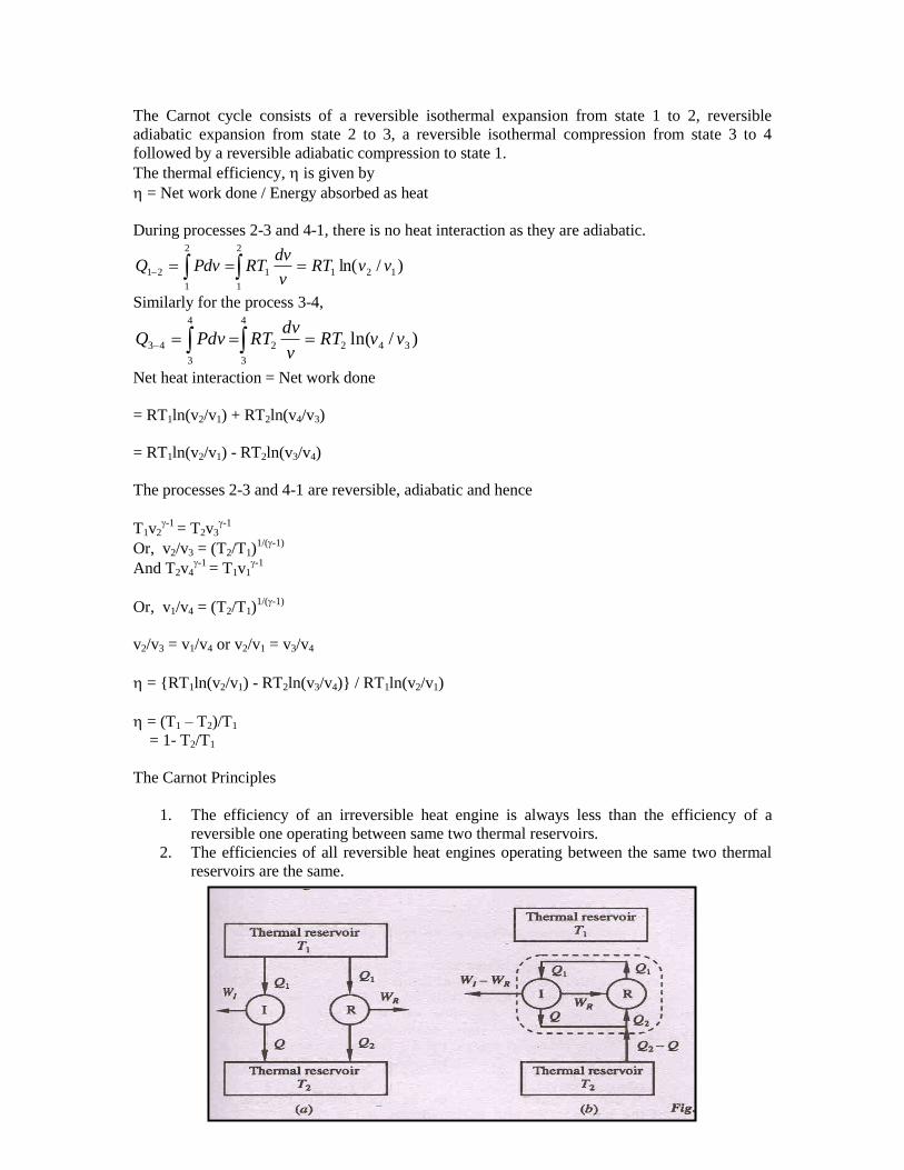
The Carnot Principles
1. The efficiency of an irreversible heat engine is always less than the efficiency of a
reversible one operating between same two thermal reservoirs.
2. The efficiencies of all reversible heat engines operating between the same two thermal
reservoirs are the same.

Lets us assume it is possible for an engine I to have an efficiency greater than the efficiency of a
reversible heat engine R.
I > R
Let both the engines absorb same quantity of energy Q1. Let Q and Q2 represent the energy
rejected as heat by the engines R, and I respectively.
WI = Q1 - Q
WR= Q1 – Q2
I = WI / Q1 = (Q1 - Q)/Q1 = 1-Q/Q1
R = WR/Q1 = (Q1 - Q2)/Q1 = 1-Q2/Q1
Since I > R,
1-Q/Q1 > 1-Q2/Q1
or, Q < Q2
Therefore, WI (= Q1-Q) > WR (=Q1 – Q2)
Since the engine R is reversible, it can be made to execute in the reverse order. Then, it will
absorb energy Q2 from the reservoir at T2 and reject energy Q1 to the reservoir at T1 when work
WR is done on it.
If now engines I and R are combined, the net work delivered by the combined device is given by
WI – WR = Q1 – Q – (Q1 – Q2) = Q2 – Q
The combined device absorbs energy (Q2 – Q) as heat from a single thermal reservoir and
delivers an equivalent amount of work, which violates the second law of thermodynamics.
Hence, R I
Carnot principle 2
Consider two reversible heat engines R1 and R2, operating between the two given thermal
reservoirs at temperatures T1 and T2.
Let R1 > R2
Q1= energy absorbed as heat from the reservoir at T1 by the engines R1 and R2, separately.
Q = energy rejected by reversible engine R1 to the reservoir at T2
Q2 = energy rejected by reversible engine R2 to the reservoir at T2.
WR1 = Q1 - Q = work done by a reversible engine R1.
WR2 = Q1 –Q2 = work done by a reversible engine R2
According to assumption,
R1 > R2
Or, 1 – Q/Q1 > 1- Q2/Q1
Q1 –Q >Q1-Q2 or WR1 >WR2
WR1 – WR2 = (Q1 –Q) – (Q1- Q2) = Q2 – Q
Since the engine R2 is reversible, it can be made to execute the cycle in the reverse by supplying
WR2.
Since WR1 > WR2 the reversible engine R2 can be run as a heat pump by utilizing part of the work
delivered by R1.
For the combined device,
WR1 – WR2 = Q2 – Q, by absorbing energy Q2 – Q from a single thermal reservoir which violates
the second law of thermodynamics.
Hence R1 > R2 is incorrect.
By similar arguments, if we assume that R2 > R1 then,
R1 R2
Therefore, based on these two equations,
R1 = R2
The efficiency of a reversible heat engine is also independent of the working fluid and depends
only on the temperatures of the reservoirs between which it operates.
Thermodynamic Temperature Scale
To define a temperature scale that does not depend on the thermometric property of a substance,
Carnot principle can be used since the Carnot engine efficiency does not depend on the working
fluid. It depends on the temperatures of the reservoirs between which it operates.

Consider the operation of three reversible engines 1, 2 and 3. The engine 1 absorbs energy Q1 as
heat from the reservoir at T1, does work W1 and rejects energy Q2 as heat to the reservoir at T2.
Let the engine 2 absorb energy Q2 as heat from the reservoir at T2 and does work W2 and rejects
energy Q3 as heat to the reservoir at T3.
The third reversible engine 3, absorbs energy Q1as heat from the reservoir at T1, does work W3
and rejects energy Q3 as heat to the reservoir at T3.
1 = W1 / Q1 = 1- Q2/Q1 = f(T1,T2)
or, Q1/Q2 = F(T1,T2)
2 = 1- Q3/Q2 = f(T2,T3)
or, T2/T3 = F(T2,T3)
3 = 1- Q3/Q1 = f(T1,T3)
T1/T3 = F(T1,T3)
Then , Q1/Q2 = (Q1/Q3)/(Q2/Q3)
Or, F(T1,T2) = F(T1,T3) /F(T2,T3)
Since T3 does not appear on the left side, on the RHS also T3 should cancel out. This is possible if
the function F can be written as
F(T1, T2) = (T1) (T2)
(T1) (T2) = {(T1) (T3)} / {(T2) (T3)}
= (T1) (T2)
Therefore, (T2) = 1 / (T2)
Hence, Q1 / Q2 = F(T1,T2) = (T1)/ (T2)

Now, there are several functional relations that will satisfy this equation. For the thermodynamic
scale of temperature, Kelvin selected the relation
Q1/Q2 = T1/T2
That is, the ratio of energy absorbed to the energy rejected as heat by a reversible engine is equal
to the ratio of the temperatures of the source and the sink.
The equation can be used to determine the temperature of any reservoir by operating a reversible
engine between that reservoir and another easily reproducible reservoir and by measuring
efficiency (heat interactions). The temperature of easily reproducible thermal reservoir can be
arbitrarily assigned a numerical value (the reproducible reservoir can be at triple point of water
and the temperature value assigned 273.16 K).
The efficiency of a Carnot engine operating between two thermal reservoirs the temperatures of
which are measured on the thermodynamic temperature scale, is given by
1 = 1- Q2/Q1 = 1 – T2/T1
The efficiency of a Carnot engine, using an ideal gas as the working medium and the temperature
measured on the ideal gas temperature scale is also given by a similar expression.
(COP)R = QL / (QH – QL) = TL / (TH – TL)
(COP)HP= QH / (QH – QL) = TH / (TH – TL)
Clausius Inequality
For a Carnot cycle
Q1/Q2=T1/T2
Or Q1/T1-Q2/T2=0 for a reversible engine.
With the usual sign convention, that is, heat flow into a system taken as positive and heat outflow
of the system taken as negative
Q1/T1+Q2/T2=0 or Qi/Ti=0
For an irreversible engine absorbing Q1 amount of heat from a reservoir at T1 and rejecting Q21 to
a reservoir at T2, then
1-Q21/Q11-Q2/Q1
or 1-Q21/Q11-T2/T1
or Q21/Q1T2/T1
or Q21/T2Q1/T1
Making use of the sign convention, we get

Q21/T2+Q1/T10
Or Q/T0 for an irreversible engine
Replacement of a Reversible process by an equivalent process
Let us consider cyclic changes in a system other than heat engines. If the cycle can be split up
into a large number of heat engine cycles then the above observation can be made use of in
relating the heat interactions with the absolute temperatures.
Any reversible process can be approximated by a series of reversible, isothermal and reversible,
adiabatic processes.
Consider a reversible process 1-2. The same change of a state can be achieved by process 1-a
(reversible adiabatic process), isothermal process a-b-c and a reversible adiabatic process c-2. The
areas 1-a-b and b-c-2 are equal. From the first law
U2-U1=Q1-a-b-c-2-W1-a-b-c-2
Consider the cycle 1-a-b-c-2-b-1. The net work of the cycle is zero. Then
01221 bcba WWdW
or
211221 bbcba WWW
The heat interaction along the path 1-a-b-c-2 is
Q1-a-b-c-2=Q1-a+Qa-b-c+Qc-2=Qa-b-c
Since 1-a and c-2 are reversible adiabatic paths. Hence
U2-U1=Qa-b-c-W1-b-2
Application of the first law of the thermodynamics to the process 1-b-2 gives
U2-U1=Q1-b-2-W1-b-2
Comparing the two equations
Qi-b-c=Q1-b-2
The heat interaction along the reversible path 1-b-2 is equal to that along the isothermal path a-b-
c. Therefore a reversible process can be replaced by a series of reversible adiabatic and reversible
isothermal processes.
Clausius Inequality
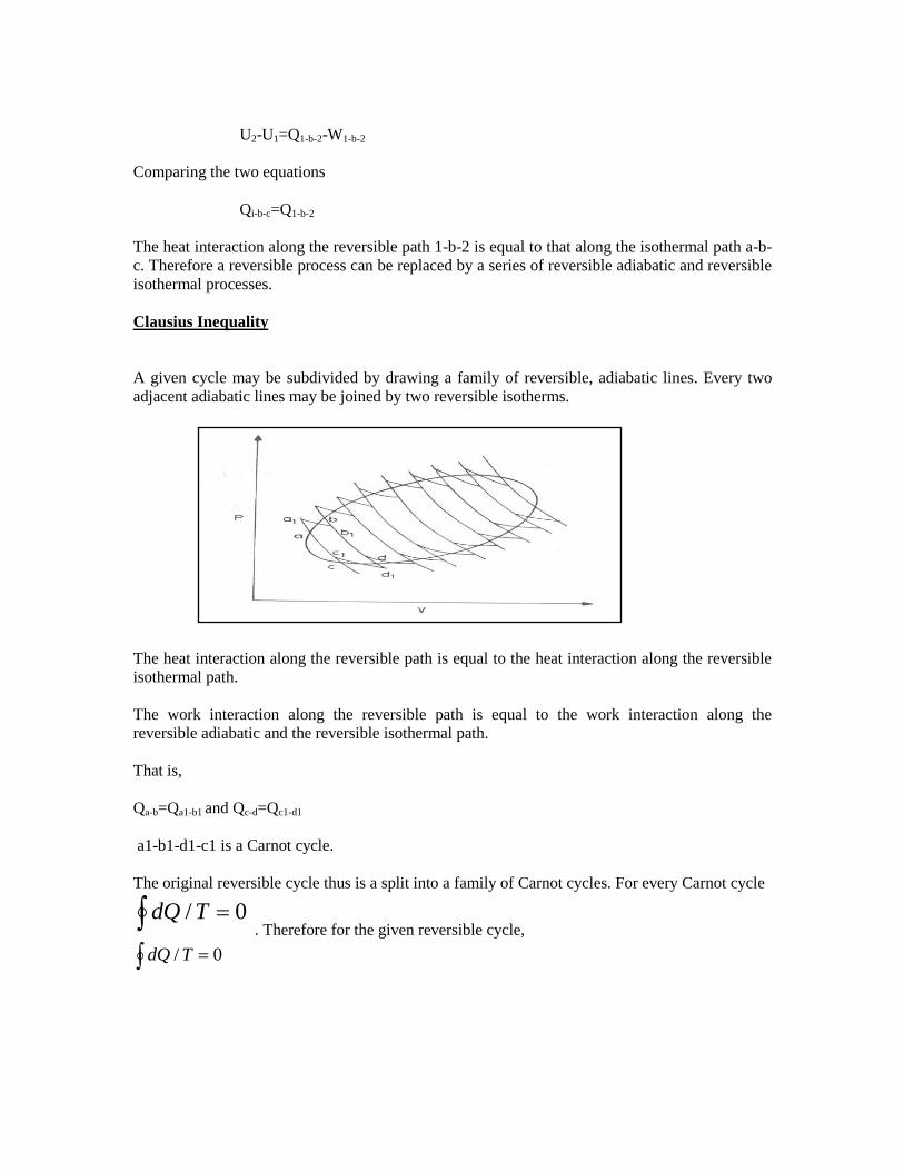
A given cycle may be subdivided by drawing a family of reversible, adiabatic lines. Every two
adjacent adiabatic lines may be joined by two reversible isotherms.
The heat interaction along the reversible path is equal to the heat interaction along the reversible
isothermal path.
The work interaction along the reversible path is equal to the work interaction along the
reversible adiabatic and the reversible isothermal path.
That is,
Qa-b=Qa1-b1 and Qc-d=Qc1-d1
a1-b1-d1-c1 is a Carnot cycle.
The original reversible cycle thus is a split into a family of Carnot cycles. For every Carnot cycle
0/ TdQ . Therefore for the given reversible cycle,
0/ TdQ
If the original cycle is irreversible
0/TdQ
so the generalized observation is
0/TdQ
Whenever a system undergoes a cyclic change, however complex the cycle may be( as long as it
involves heat and work interactions), the algebraic sum of all the heat interactions divided by the
absolute temperature at which heat interactions are taking place considered over the entire cycle
is less than or equal to zero (for a reversible cycle).
Entropy
1. T
dQ
has the same value irrespective of path as long as path is reversible
2. RT
dQ
is an exact differential of some function which is identical as entropy
3.
2
1
2
1
12RT
dQdSSSS
4. RT
dQdS
for reversible process only
Calculation of Entropy change
1. Entropy is a state function. The entropy change is determined by its initial and final
states only
2. In analyzing irreversible process, it is not necessary to make a direct analysis of actual
reversible process.
Substitute actual process by an imaginary reversible process. The entropy change for imaginary
reversible process is same as that of an irreversible process between given final and initial states.
(a) Absorption of energy by a constant temperature reservoir
Energy can be added reversibly or irreversibly as heat or by performing work.
RT
dQS

Example:-
The contents of a large constant-temperature reservoir maintained at 500 K are continuously
stirred by a paddle wheel driven by an electric motor. Estimate the entropy change of the
reservoir if the paddle wheel is operated for two hours by a 250W motor.
Paddle wheel work converted into internal energy- an irreversible process. Imagine a reversible
process with identical energy addition
kJ
T
Q
T
dQS
R
6.0500
)3600(225.0
(b) Heating or cooling of matter
UQ for constant volume heating
HQ
for constant pressure heating
2
11
2ln
T
T
ppT
TmC
T
dTCm
T
dQS
for constant pressure
2
11
2ln
T
T
vvT
TmC
T
dTCm
T
dQS
, for constant volume process
Example: -
Calculate entropy change if 1kg of water at 300 C is heated to 80
0C at 1 bar pressure. The specific
heat of water is 4.2kJ/kg-K
Kkg
kJ
T
TCS p
.6415.0
30273
80273ln102.4ln 3
1
2
(c) Phase change at constant temperature and pressure
sf
sf
sfT
h
T
dQS
T
h
T
dQS
fg
fg

Example:-
Ice melts at 00C with latent heat of fusion= 339.92 kJ/kg. Water boils at atmospheric pressure at
1000C with hfg= 2257 kJ/kg.
Kkg
kJSsf
.2261.1
15.273
92.334
Kkg
kJS fg
.0485.6
15.373
2257
(d) Adiabatic mixing
Example:-
A lump of steel of mass 30kg at 4270 C is dropped in 100kg oil at 27
0C.The specific heats of steel
and oil is 0.5kJ/kg-K and 3.0 kJ/kg-K respectively. Calculate entropy change of steel, oil and
universe.
T= final equilibrium temperature.
oilpsteelp TmCTmC
)300(3100)700(5.0300 TT
or T=319K
KkJS universe /6343.64226.187883.11)(
Tds relations
From the definition of entropy,
dQ = Tds
KkJ
T
TmCS
oil
poil
/4226.18300
319ln3100
1
2ln)(
KkJ
T
TmC
T
dTmC
T
dQS
steel
p
p
steel
/7883.11700
319ln5.030
1
2ln)(
2
1
2
1

From the first law of thermodynamics,
dW = PdV
Therefore,
TdS = dU + PdV
Or, Tds = du + Pdv
This is known as the first Tds or, Gibbs equation.
The second Tds equation is obtained by eliminating du from the above equation using the
definition of enthalpy.
h = u + Pv dh = du + vdP
Therefore, Tds = dh – vdP
The two equations can be rearranged as
ds = (du/T) + (Pdv/T)
ds = (dh/T) – (vdP/T)
Change of state for an ideal gas
If an ideal gas undergoes a change from P1, v1, T1 to P2, v2, T2 the change in entropy can be
calculated by devising a reversible path connecting the two given states.
Let us consider two paths by which a gas can be taken from the initial state, 1 to the final state, 2.
The gas in state 1 is heated at constant pressure till the temperature T2 is attained and then it is
brought reversibly and isothermally to the final pressure P2.
Path 1-a: reversible, constant-pressure process.
Path a-2: reversible, isothermal path
s1-a = dq/T = Cp dT/T = Cp ln(T2/T1)
sa-2 = dq/T = (du+Pdv)/T = (Pdv)/T = Rln(v2/va)
(Since du = 0 for an isothermal process)
Since P2v2 = Pava = P1va
Or, v2/va = P1/P2
Or, sa-2 = -Rln(P2/P1)
Therefore, s = s1-a + sa-2
= Cp ln(T2/T1) – Rln(P2/P1)
Path 1-b-2: The gas initially in state 1 is heated at constant volume to the final temperature T2 and
then it is reversibly and isothermally changed to the final pressure P2.
1-b: reversible, constant volume process
b-2: reversible, isothermal process
s1-b = Cv ln(T2/T1)
sb-2 =Rln(v2/v1)
or, s = Cv ln(T2/T1)+ Rln(v2/v1)
The above equation for s can also be deduced in the following manner:
ds = (dq/T)R = (du + Pdv)/T = (dh – vdP)/T
or,
Principle of increase of entropy
Let a system change from state 1 to state 2 by a reversible process A and return to state 1 by
another reversible process B. Then 1A2B1 is a reversible cycle. Therefore, the Clausius
inequality gives:
If the system is restored to the initial
state from 1 to state 2 by an irreversible process C, then 1A2C1 is an irreversible cycle. Then the
Clausius inequality gives:
Subtracting the above equation from the first one,
2 2
1 1
2 2
1 1
2
2 2
1 11
( )
ln ln
Similarly,
( )ln ln
v
v
p
C dTdu pdv Rdvs
T T v
T vC R
T v
T Pdh vdps C R
T T P
121 21 12
///BA A B
otdQTdQTdQ
121 21 12
///CA A C
otdQTdQTdQ
12 12
//B C
TdQTdQ

Since the process 2B1 is reversible,
Where the equality sign holds good for a reversible process and the inequality sign holds good for
an irreversible process.
Now let us apply the above result to evaluate the entropy change of the universe when a system
interacts with its surroundings and exchanges energy as heat with the surroundings.
Let Tsur and Tsys be the temperatures of the surroundings and the system such that Tsur >Tsys. Let
dQ represent the energy transfer as heat from t he surroundings to the system during the given
irreversible process.
dSsys = dQ/Tsys
dSsur = -dQ/Tsur
dSuni = dSsys + dSsur = (dQ/T)sys – (dQ/T)sur >0
Suni >0 (since Tsur>Tsys)
If the system is isolated, there is no change in the entropy of the surroundings and
S 0, for an isolated system
Therefore the entropy of an isolated system either increases or, in the limit, remains constant.
The equality sign holds good when the process undergone by the system is reversible, the
inequality sign holds good if there is any irreversibility present in the process. This statement is
usually called the principle of entropy increase.
Irreversible or spontaneous processes can occur only in that direction for which the
entropy of the universe or that of an isolated system, increases. These processes cannot
occur in the direction of decreasing entropy.
For an isolated system,
S > 0, for irreversible processes
S = 0, for reversible processes
S < 0, the process is impossible
12
2
1
//B
TdQTdQ
Example:
One kg of superheated steam at 0.2MPa and 2000C contained in a piston cylinder assembly is
kept at ambient conditions of 300K till the steam is condensed to saturated liquid at constant
pressure. Calculate the change in the entropy of the universe with this process.
Solution:
Initial state of the steam: superheated at 0.2 MPa and 200oC
h1= 2870.4 kJ/kg; and s1 = 7.5033 kJ/kgK
Final state: saturated liquid at 0.2 MPa.
h2 = 504.52 kJ/kg and s2 = 1.5295 kJ/kgK
Hence Ssteam = s2 – s1 = 1.5295 – 7.5033 =
-5.9738 kJ/kgK
For a constant pressure process: q = h
Therefore, q = h2 – h1 = 504.52 – 2870.4 =
-2365.68 kJ
Entropy change of the surroundings = Ssur = Q/Tsur = 2365.88/300 = 7.886 kJ/K
Hence, Suni = Ssys + Ssur = -5.9738 +7.886 = 1.9122 kJ/K
Suni > 0 and hence the process is irreversible and feasible.
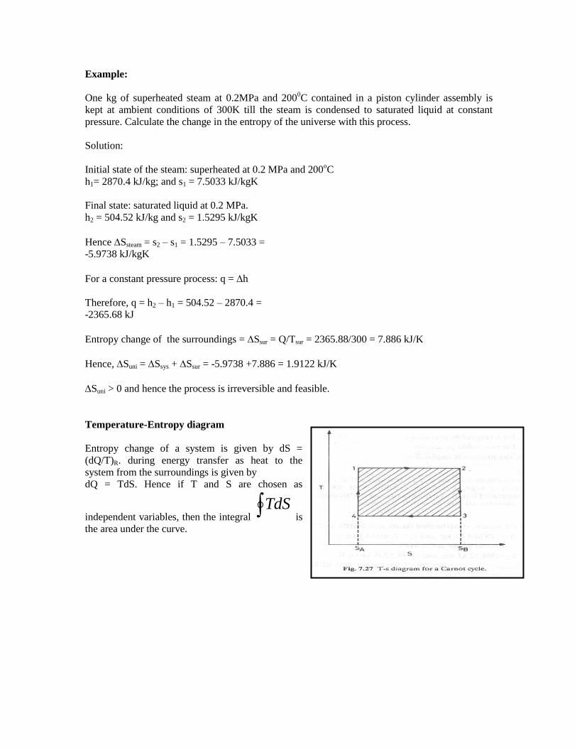
Temperature-Entropy diagram
Entropy change of a system is given by dS =
(dQ/T)R. during energy transfer as heat to the
system from the surroundings is given by
dQ = TdS. Hence if T and S are chosen as
independent variables, then the integral TdS
is
the area under the curve.
The first law of thermodynamics gives
dU = dQ - dW
also for a reversible process,


Thermodynamic relations
Gibbs Function and Helmoltz Function
Gibbs equation is
du = Tds – Pdv
The enthalpy h can be differentiated,
dh = du + pdv + vdP
Combining the two results in
dh = Tds + vdP
The coefficients T and v are partial derivative of h(s,P),
vP
h
Ts
h
s
P
Since v > 0, an isentropic increase in pressure will result in an increase in enthalpy.
We introduce Helmholtz function
a = u – Ts
Combine Gibbs equation with the differential of a,
da = -Pdv – sdT
The coefficient –P and –s are the partial derivatives of f(v,T), so
sT
a
Pv
a
v
T
Similarly, using the Gibbs function
g = h – Ts
dg = vdP – sdT
Consequently,
sT
g
vP
g
P
T
Note:
1. The decrease in Helmholtz function of a system sets an upper limit to the work done in any
process between two equilibrium states at the same temperature during which the system
exchanges heat only with a single reservoir at this temperature. Since the decrease in the
Helmholtz potential represents the potential to do work by the system, it is also a thermodynamic
potential.
2. The decrease in Gibbs function of a system sets an upper limit to the work, exclusive of “pdv”
work in any process between two states at the same temperature and pressure, provided the
system exchanges heat only with a single reservoir at this temperature and that the surroundings
are at a constant pressure equal to that in the end states of the pressure.
The maximum work is done when the process is isothermal isobaric. Gibbs function is also called
Chemical Potential.
Some important property relations
dz(x,y) = Mdx + Ndy
where, M = yx
z
N = xy
Z
Mathematically, we would say that dz is an exact differential, which simply means that z is a
continuous function of the two independent variables x and y. Since the order in which a second
partial derivative is taken is unimportant, it follows that,
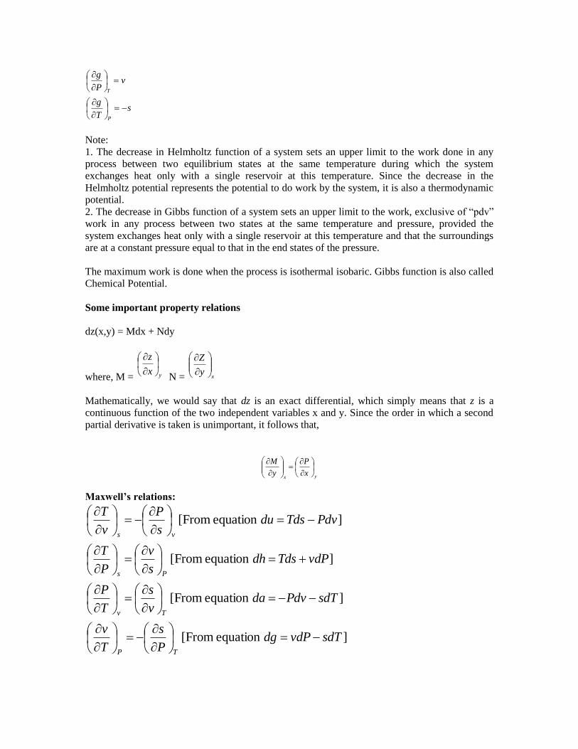
Maxwell’s relations:
]equation [From
]equation [From
]equation [From
]equation [From
sdTvdPdgP
s
T
v
sdTPdvdav
s
T
P
vdPTdsdhs
v
P
T
PdvTdsdus
P
v
T
TP
Tv
Ps
vs
yxx
P
y
M
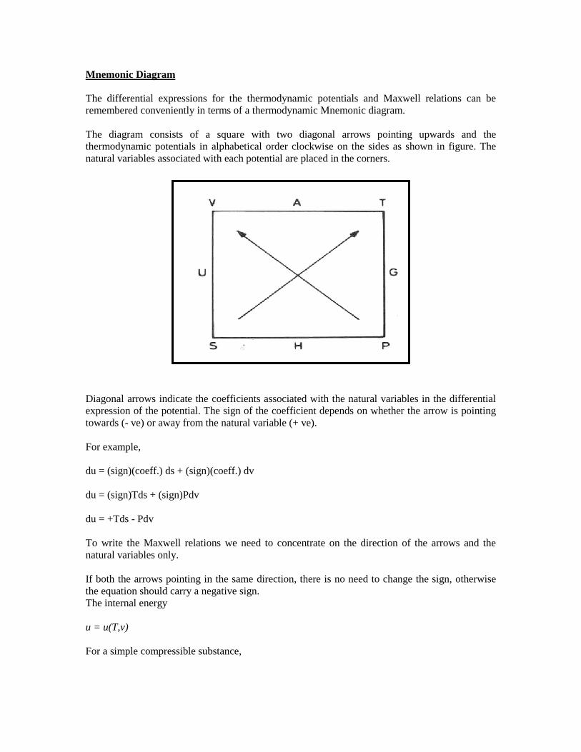
Mnemonic Diagram
The differential expressions for the thermodynamic potentials and Maxwell relations can be
remembered conveniently in terms of a thermodynamic Mnemonic diagram.
The diagram consists of a square with two diagonal arrows pointing upwards and the
thermodynamic potentials in alphabetical order clockwise on the sides as shown in figure. The
natural variables associated with each potential are placed in the corners.
Diagonal arrows indicate the coefficients associated with the natural variables in the differential
expression of the potential. The sign of the coefficient depends on whether the arrow is pointing
towards (- ve) or away from the natural variable (+ ve).
For example,
du = (sign)(coeff.) ds + (sign)(coeff.) dv
du = (sign)Tds + (sign)Pdv
du = +Tds - Pdv
To write the Maxwell relations we need to concentrate on the direction of the arrows and the
natural variables only.
If both the arrows pointing in the same direction, there is no need to change the sign, otherwise
the equation should carry a negative sign.
The internal energy
u = u(T,v)
For a simple compressible substance,

dvPv
u
TdT
T
Cds
dvv
udTCdu
T
v
T
v
1
Taking entropy as a function of temperature and volume,
Using thrid Maxwell's relation,
1
From this we obtain
u
v
v
v
T v T
T v
Cs
T T
s P uP
v T T v
PT P
T
This important equation expresses the dependence of the internal energy on the volume at fixed
temperature solely in terms of measurable T, P and v. This is helpful in construction of tables for
u in terms of measured T, P and v.
For a perfect gas,
Pv = RT
u0
v
v
T
P R
T v
RT P P P
v
This implies that, for a perfect gas, internal energy is independent of density and depends only on
T.
v
v
C Pds dT dv
T T
Similarly it can be shown using Fourth Maxwell’s relation that
P
P
C vds dT dP
T T
Using the above two equations and solving for dP,
( / )
( / ) /
P v v
P P
C C P TdP dT dv
T v T u T
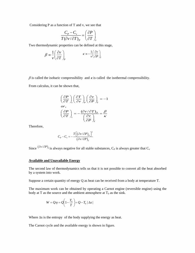
Considering P as a function of T and v, we see that
Two thermodynamic properties can be defined at this stage,
is called the isobaric compressibility and is called the isothermal compressibility.
From calculus, it can be shown that,
Therefore,
Since /T
v P is always negative for all stable substances, CP is always greater that Cv
Available and Unavailable Energy
The second law of thermodynamics tells us that it is not possible to convert all the heat absorbed
by a system into work.
Suppose a certain quantity of energy Q as heat can be received from a body at temperature T.
The maximum work can be obtained by operating a Carnot engine (reversible engine) using the
body at T as the source and the ambient atmosphere at T0 as the sink.
Where s is the entropy of the body supplying the energy as heat.
The Carnot cycle and the available energy is shown in figure.
( / )
P v
vP
C C P
T v T T
1
P
v
v T
1
T
v
v P
1
,
( / )
v P T
P
v
T
P T v
T v P
or
v TP
vT
P
2
/
/
P
P v
T
T v PC C
v P
||1 00 sTQ
T
TQQW

The area 1-2-3-4 represents the available energy.
The shaded area 4-3-B-A represents the energy, which is discarded to the ambient atmosphere,
and this quantity of energy cannot be converted into work and is called Unavailable energy.
Suppose a finite body is used as a source. Let a large number of differential Carnot engines be
used with the given body as the source.
If the initial and final temperatures of the source are T1 and T2 respectively, the total work done or
the available energy is given by
||
1
0
00
2
1
2
1
sTQorW
T
dQTQ
T
TdQdQW
T
T
T
T
Loss in Available Energy
Suppose a certain quantity of energy Q is transferred from a body at constant temperature T1 to
another body at constant temperature T2 (T2<T1).
Initial available energy, with the body at T1,
T
TQ 01
Final available energy, with the body at T2,
2
01T
TQ
Loss in available energy
unisTT
Q
T
QT
T
TQ
T
TQ
0
12
0
2
0
1
0 11
T
TdQdQdW 01
where suni is the change in the entropy of the universe.
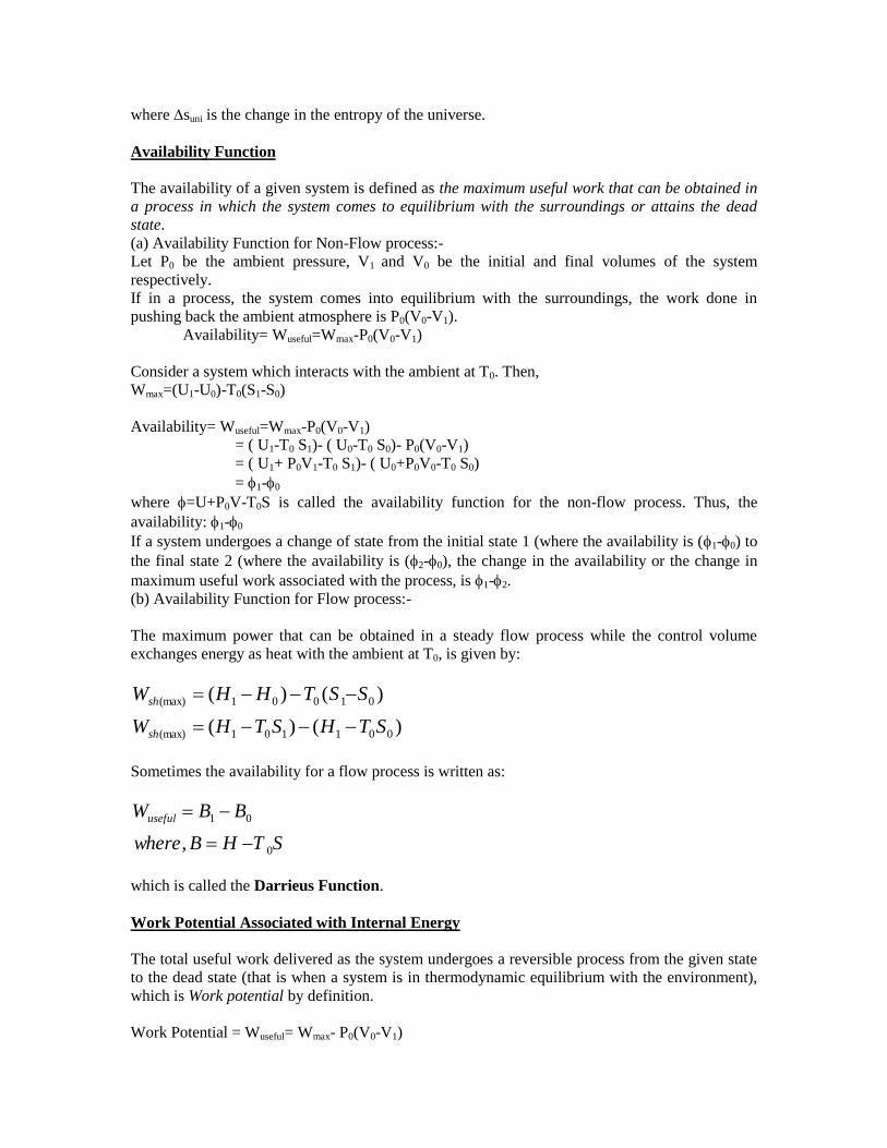
Availability Function
The availability of a given system is defined as the maximum useful work that can be obtained in
a process in which the system comes to equilibrium with the surroundings or attains the dead
state.
(a) Availability Function for Non-Flow process:-
Let P0 be the ambient pressure, V1 and V0 be the initial and final volumes of the system
respectively.
If in a process, the system comes into equilibrium with the surroundings, the work done in
pushing back the ambient atmosphere is P0(V0-V1).
Availability= Wuseful=Wmax-P0(V0-V1)
Consider a system which interacts with the ambient at T0. Then,
Wmax=(U1-U0)-T0(S1-S0)
Availability= Wuseful=Wmax-P0(V0-V1)
= ( U1-T0 S1)- ( U0-T0 S0)- P0(V0-V1)
= ( U1+ P0V1-T0 S1)- ( U0+P0V0-T0 S0)
= 1-0
where =U+P0V-T0S is called the availability function for the non-flow process. Thus, the
availability: 1-0
If a system undergoes a change of state from the initial state 1 (where the availability is (1-0) to
the final state 2 (where the availability is (2-0), the change in the availability or the change in
maximum useful work associated with the process, is 1-2.
(b) Availability Function for Flow process:-
The maximum power that can be obtained in a steady flow process while the control volume
exchanges energy as heat with the ambient at T0, is given by:
)()(
)()(
001101(max)
01001(max)
STHSTHW
SSTHHW
sh
sh
Sometimes the availability for a flow process is written as:
STHBwhere
BBWuseful
0
01
,
which is called the Darrieus Function.
Work Potential Associated with Internal Energy
The total useful work delivered as the system undergoes a reversible process from the given state
to the dead state (that is when a system is in thermodynamic equilibrium with the environment),
which is Work potential by definition.
Work Potential = Wuseful= Wmax- P0(V0-V1)
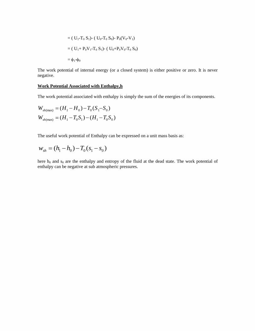
= ( U1-T0 S1)- ( U0-T0 S0)- P0(V0-V1)
= ( U1+ P0V1-T0 S1)- ( U0+P0V0-T0 S0)
= 1-0
The work potential of internal energy (or a closed system) is either positive or zero. It is never
negative.
Work Potential Associated with Enthalpy,h
The work potential associated with enthalpy is simply the sum of the energies of its components.
)()(
)()(
001101(max)
01001(max)
STHSTHW
SSTHHW
sh
sh
The useful work potential of Enthalpy can be expressed on a unit mass basis as:
)()( 01001 ssThhwsh
here h0 and s0 are the enthalpy and entropy of the fluid at the dead state. The work potential of
enthalpy can be negative at sub atmospheric pressures.
UNIT-III
PURE SUBSTANCES AND GAS LAWS
The term saturation temperature designates the temperature at which vaporization takes place.
For water at 99.6 C the saturation pressure is 0.1 M Pa, and for water at 0.1 Mpa, the saturation
temperature is 99.6 C.
If a substance exists as liquid at the saturation temperature and pressure it is called saturated
liquid.
If the temperature is of the liquid is lower than saturation temperature at the existing pressure it is
called sub-cooled liquid or compressed liquid.
1. When a substance exists as part liquid and part vapor at the saturation temperature, its
quality is defined as the ratio of the mass of vapor to the total mass.
2. If a substance exists as vapor at the saturation temperature, it is called a saturated vapor.
3. When the vapor is at a temperature greater than the saturation temperature, it is said to
exist as superheated vapor.
4. At the critical point, the saturated liquid and saturated vapor state are identical.
5. At supercritical pressures, the substance is simply termed fluid rather than liquid or
vapor.
6. If the initial pressure at –200C is 0.260 kPa, heat transfer results in increase of
temperature to –100C. Ice passes directly from the solid phase to vapor phase.
7. At the triple point (0.6113 kPa) and a temperature of –200C, let heat transfer increase the
temperature until it reaches 0.010C. At this point, further heat transfer may cause some
ice to become vapor and some to become liquid. The three phases may be present
simultaneously in equilibrium.
Tables of Thermodynamic Properties
Tables of thermodynamic properties of many substances are available, and in general, all these
have same form.
Steam tables are selected because steam is used extensively in power plants and industrial
processes.
The steam tables provide the data of useful thermodynamic properties like T, P, v, u, h and s for
saturated liquid, saturated vapor and superheated vapor.
Since the properties like internal energy, enthalpy and entropy of a system cannot be directly
measured; they are related to change in the energy of the system.
Hence one can determine Δu, Δh, Δs, but not the absolute values of these properties. Therefore it
is necessary to choose a reference state to which these properties are arbitrarily assigned some
numerical values.

For water, the triple point (T = 0.01o C and P = 0.6113 kPa) is selected as the reference state,
where the internal energy and entropy of saturated liquid are assigned a zero value.
In the saturated steam tables, the properties of saturated liquid that is in equilibrium with
saturated vapor are presented.
During phase transition, the pressure and temperature are not independent of each other. If the
temperature is specified, the pressure at which both phases coexist in equilibrium is equal to the
saturation pressure.
Hence, it is possible to choose either temperature or pressure as the independent variable, to
specify the state of two-phase system.
Depending on whether the temperature or pressure is used as the independent variable, the tables
are called temperature or pressure tables.
The two phases- liquid and vapor can coexist in a state of equilibrium only up to the critical
point.
Therefore the listing of the thermodynamic properties of steam in the saturated steam tables ends
at the critical point (374.15o C and 212.2 bar).
If the steam exists in only one phase (superheated steam), it is necessary to specify two
independent variables, pressure and temperature, for the complete specification of the state. In the
superheated steam tables, the properties- v, u, h, and s- are tabulated from the saturation
temperature to some temperature for a given pressure.
The thermodynamic properties of a liquid and vapor mixture can be evaluated in terms of its
quality. In particular, the specific volume, specific internal energy, specific enthalpy and specific
entropy of a mixture of quality X are given by
v = (1-X)vf + Xvg, u = (1-X)uf + Xug, h = (1-X)hf + Xhg = hf + Xhfg, s = (1-X)sf + Xhg
where hfg = hg - hf = latent hat of vaporization.
Temperature-volume diagram
The locus of all the saturated states gives the saturated liquid curve AC and the locus of all the
saturated vapor states gives the saturated vapor states gives the saturated vapor states gives the
saturated vapor curve BC.
The point C represents the critical point. The difference between vg and vf reduces as the
pressure is increased, and at the critical point vg = vf .
At the critical point, the two phases-liquid and vapor- are indistinguishable.
Pressure-volume diagram
The pressure-volume (P-V) diagram for a pure substance is shown in Figure. The curves AC and
BC represent the saturated liquid curve and saturated vapor curve, respectively, and C is critical
point.
The area under the curve represents the two-phase region. Any point M in this region is a
mixture of saturated liquid (shown as f) and saturated vapor (g).
Mollier (h-s) Diagram

The h-s diagram was introduced by Richard Mollier and was named after him.
It consists of a family of constant pressure lines, constant temperature lines and constant volume
lines plotted on enthalpy versus entropy coordinates.
In the two-phase region, the constant pressure and constant temperature lines coincide.
Problems on Mollier chart and steam tables
Determine the enthalpy of water at 100o C and 15 MPa (a) by using compressed liquid tables, (b)
by approximating it as a saturated liquid, and (c) by using the correction factor.
At 100oC, the saturation pressure of water is 101.35 kPa, and since P>Psat, the water exists as a
compressed liquid at the specified state.
(a) from the compressed liquid tables,
P = 15 Mpa, T = 100oC, h = 430.28 kJ/kg
This is the exact value.
(b) Approximating the compresses liquid as a saturated liquid at 100oC, as is commonly
done, we obtain
h = hf@100 C = 419.04 kJ/kg
This value is in error by about 2.6 percent.
(c) From equation
h@ P,T = hf@T + vf@T (P – Psat)
= 419.04 + 0.001(15000 – 101.35) kJ/kg
= 434.60 kJ/kg
Problem # 1 (Nozzle)
Nitrogen gas flows into a convergent nozzle at 200 kPa, 400 K and very low velocity. It flows out
of the nozzle at 100 kPa, 330 K. If the nozzle is insulated, find the exit velocity.
Vi = 0
Adiabatic nozzle
The SSSF equation:
Ve2/2 = (hi – he) = Cp(Ti – Te)
= {Ru/M(-1)} (Ti – Te)
= {1.4 * 8314/(28*0.4)}(400-330)
= 72747.5 m2/s
2
We get, Ve = 381.44 m/s
Problem # 2 (Diffuser)
Air at 10o C and 80 kPa enters the diffuser of a jet engine steadily with a velocity of 200 m/s. The
inlet area of the diffuser is 0.4 m2. The air leaves the diffuser with a velocity that is very small
compared with the inlet velocity. Determine (a) the mass flow rate of the air and (b) the
temperature of the air leaving the diffuser.

Solution:
Assumptions: This is a steady flow
process. Air is an ideal gas. The
potential energy change is zero. Kinetic
energy at diffuser exit is negligible.
There are no work interactions. Heat transfer is
negligible.
To determine the mass flow rate, we need the specific volume of air.
v1 = RT1/ P1 = 0.287 * 283 / 80 = 1.015 m3/kg
m = 1/v1(V1A1) = (200 * 0.4)/ 1.015 = 78.8 kg/s
For steady flow, mass flow through the diffuser is constant.
(b) (h1 + V12/2) = (h2 + V2
2/2) (since Q = 0, W = 0, and PE = 0)
h2 = h1 – (V22- V1
2)/2
The exit velocity of a diffuser is very small and therefore neglected.
h2 = h1 + V12/2
T2 = T1 + V12/2Cp
T2 = 283 + 2002/(2*1004)
= 302.92 K
Compressing air by a compressor
Air at 100 kPa and 280 K is compressed steadily to 600 kPa and 400 K. The mass flow rate of air
is 0.02 kg/s and a heat loss of 16 kJ/kg occurs during the process. Assuming the changes in KE
and PE are negligible, determine the necessary power input to the compressor.

We take the compressor as the system. This is a control volume since the mass crosses the system
boundary during the process. Heat is lost from the system and work is supplied to the system.
With similar assumptions as in the diffuser problem,
w = q + (h2 – h1)
The input power = m (q + (h2 – h1))
= 0.02 (16 + (1.004*(400 – 280)))
= 2.73 kW
Power generation by a steam turbine
The power output of an adiabatic steam turbine is 5 MW, and the inlet and exit conditions of the
steam are as indicated in the figure.
(a) Compare the magnitude of h, KE, and PE
(b) Determine the work done per unit mass of the steam flowing through the turbine
(c) Calculate the mass flow rate of the steam.
We take the turbine as a system. The control volume is shown in the figure. The system, the inlet
and exit velocities do work and elevations are given and thus the kinetic and potential energies
are to be considered.
At the inlet, the steam is in superheated vapor state.
h1 = 3247.6 kJ/kg.
At the turbine exit, we have a saturated liquid-vapor mixture at 15 kPa pressure. The enthalpy at
this state is
h2 = hf + x2hfg
= 225.94 + 0.9 * 2373.1
= 2361.73 kJ/kg
h = h2 – h1
= 2361.73 – 3247.6 = -885.87 kJ/kg

ke = (V22- V1
2)/2 = (180
2-50
2)/2*1000
= 14.95 kJ/kg
Pe = g(Z2-Z1) = 9.807 * (6 –10)/1000
= -0.04 kJ/kg
wout = -[( h2 – h1) +(V22- V1
2)/2 + g(Z2-Z1)]
= -[-885.87 + 14.95 – 0.04]
= 870.96 kJ/kg
(d) The required mass flow rate for a 5MW power output is 5000/870.96 = 5.74 kg/s
Clapeyron Equation
To find out the dependence of pressure on equilibrium temperature when two phases coexist.
Along a phase transition line, the pressure and temperature are not independent of each other,
since the system is univariant, that is, only one intensive parameter can be varied independently.
When the system is in a state of equilibrium, i.e., thermal, mechanical and chemical equilibrium,
the temperature of the two phases has to be identical, the pressure of the two phases has to be
equal and the chemical potential also should be the same in both the phases.
Representing in terms of Gibbs free energy, the criterion of equilibrium is:
0^
gd at constant T and P
or, 0^^^
dPvdTsgd
Consider a system consisting of a liquid phase at state 1 and a vapour phase at state 1’ in a state
of equilibrium. Let the temperature of the system is changed from T1 to T2 along the vaporization
curve.
For the phase transition for 1 to 1’:
0^^^
dPvdTsgd
or vaporphaseeliquidphas gg^^
or 2
^
1
^
gg
In reaching state 2 from state 1, the change in the Gibbs free energy of the liquid phase is given
by:
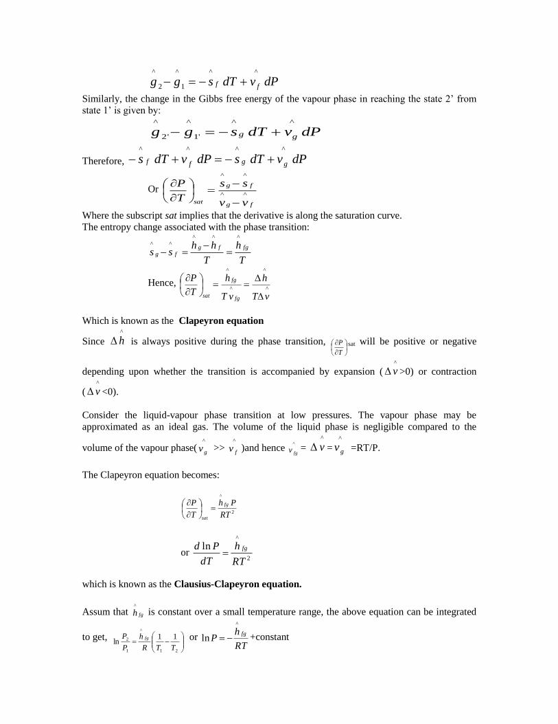
dPvdTsgg ff
^^
1
^
2
^
Similarly, the change in the Gibbs free energy of the vapour phase in reaching the state 2’ from
state 1’ is given by:
dPvdTsgg gg
^^
'1
^
'2
^
Therefore, dPvdTsdPvdTs ggff
^^^^
Or
fg
fg
sat vv
ss
T
P^^
^^
Where the subscript sat implies that the derivative is along the saturation curve.
The entropy change associated with the phase transition:
T
h
T
hhss
fgfgfg
^^^^^
Hence, ^
^
^
^
vT
h
vT
h
T
P
fg
fg
sat
Which is known as the Clapeyron equation
Since ^
h is always positive during the phase transition,
T
P sat will be positive or negative
depending upon whether the transition is accompanied by expansion (^
v >0) or contraction
(^
v <0).
Consider the liquid-vapour phase transition at low pressures. The vapour phase may be
approximated as an ideal gas. The volume of the liquid phase is negligible compared to the
volume of the vapour phase(^
gv >> ^
fv )and hence ^
fgv = ^
v =^
gv =RT/P.
The Clapeyron equation becomes:
2
^
RT
Ph
T
P fg
sat
or 2
^
ln
RT
h
dT
Pd fg
which is known as the Clausius-Clapeyron equation.
Assum that fgh^
is constant over a small temperature range, the above equation can be integrated
to get,
21
^
1
2 11ln
TTR
h
P
P fg or RT
hP
fg
^
ln +constant

Hence, a plot of lnP versus 1/T yields a straight line the slope of which is equal to –(hfg/R).
For a solid-to-liquid transition, it is a reasonably good approximation to assume that the molar
heat capacity and the molar volume are constant in each phase and the coefficient of volume
expansion is negligible for each phase. Then,
T
CC
T
Th pspfsf
^^^
)/(
where ^
sfh is the latent heat of fusion.
For the transition from liquid phase to vapour phase, the molar volume of the liquid phase can be
neglected compared to the molar volume of the gas phase, and g>>f. The vapour phase may be
approximated as an ideal gas. Then g=1/T. It is clear that vgg> vff. Hence,
)(^^
^
pfpgfg
CCT
h
Phase Equilibrium- Gibbs Phase Rule
The number of independent variables associated with a multi component, multiphase system is
given by the Gibbs Phase Rule, expressed as,
F=C+2-P
Where,
F= The number of independent variables
C= The number of components
P= The number of phases present in the equilibrium
For a single component (C=1) two phase (P=2) system, one independent intensive
property needs to be specified (F=1).
At the triple point, for C=1, P=3 and thus F=0. None of the properties of a pure substance
at the triple point can be varied.
Two independent intensive properties need to be specified to fix the equilibrium state of a
pure substance in a single phase.
Phase diagram for a single component system is given in figure.
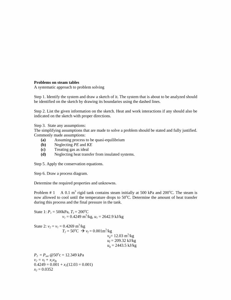
Problems on steam tables
A systematic approach to problem solving
Step 1. Identify the system and draw a sketch of it. The system that is about to be analyzed should
be identified on the sketch by drawing its boundaries using the dashed lines.
Step 2. List the given information on the sketch. Heat and work interactions if any should also be
indicated on the sketch with proper directions.
Step 3. State any assumptions:
The simplifying assumptions that are made to solve a problem should be stated and fully justified.
Commonly made assumptions:
(a) Assuming process to be quasi-equilibrium
(b) Neglecting PE and KE
(c) Treating gas as ideal
(d) Neglecting heat transfer from insulated systems.
Step 5. Apply the conservation equations.
Step 6. Draw a process diagram.
Determine the required properties and unknowns.
Problem # 1 A 0.1 m3 rigid tank contains steam initially at 500 kPa and 200
oC. The steam is
now allowed to cool until the temperature drops to 50oC. Determine the amount of heat transfer
during this process and the final pressure in the tank.
State 1: P1 = 500kPa, T1 = 200oC
v1 = 0.4249 m3/kg, u1 = 2642.9 kJ/kg
State 2: v2 = v1 = 0.4269 m3/kg
T2 = 50oC vf = 0.001m
3/kg
vg= 12.03 m3/kg
uf = 209.32 kJ/kg
ug = 2443.5 kJ/kg
P2 = Psat @50oc = 12.349 kPa
v2 = vf + x2vfg
0.4249 = 0.001 + x2(12.03 = 0.001)
x2 = 0.0352

u2 = uf +x2ug
= 209.32 +(0.0352)(2443.5 – 209.32)
= 288.0 kJ/kg
m = V/u = (0.1 m3/kg)/(0.4249 m
3/kg)
= 0.235 kg
-Qout = U = m(u2 – u1)
Qout = m(u1 – u2)
= (0.235)(2642.9 – 288) = 553.4 kg
Problem # 2 A piston/cylinder contains 50 kg of water at 200 kPa with a volume of 0.1 m3 . Stop
in the cylinder is placed to restrict the enclosed volume to 0.5 m3. The water is now heated until
the piston reaches the stops. Find the necessary heat transfer.
At 200 kPa,
vf = 0.001061 m3/kg
vfg = 0.88467 m3/kg
hf = 504.68 kJ/kg
hfg = 2201.96 kJ/kg
This is a constant pressure process. Hence,
Q = H
The specific volume initially,
vi = 0.1 /50 = 0.002 m3/kg
v = vf + x vfg
= 0.001061 + x (0.88467)
Therefore, x = (0.002 – 0.001061) / 0.88467
= 0.001061
h = hf + x hfg
= 504.68 + 0.001061(2201.96)
= 507.017 kJ/kg
vfinal = 0.5 /50 = 0.01 m3/kg
v = vf + x vfg
Therefore, x = (0.01 – 0.001061) / 0.88467
= 0.01
hfinal = 504.68 + 0.01(2201.96)
= 526.69 kJ/kg
Q = H = 50 (526.69 - 507.017)
= 983.65 kJ/kg
Problem # 3 A rigid insulated tank is separated into two rooms by a stiff plate. Room A of 0.5 m3
contains air at 250 kPa, 300 K and room B of 1 m3 has air at 150 kPa, 1000 K. The plate is
removed and the air comes to a uniform state without any heat transfer. Find the final pressure
and temperature.

The system comprises of room A and B together. This is a constant internal energy process as
there is no heat and work exchange with the surroundings.
mA = PAVA / RTA
= (250 x 1000 x 0.5) / (287 x 300)
= 1.452 kg
mB = PBVB / RTB
= (150 x 1000 x 1.0) / (287 x 1000)
= 0.523 kg
UA + UB = 0
Let Tf be the final temperature at equilibrium
mA (Tf – 300) + mB (Tf – 1000) = 0
1.452 (Tf – 300) + 0.523 (Tf – 1000) = 0
Tf = 485.37 K
Pf = (1.452 + 0.523) x 287 x 485.37 / 1.5
= 183.41 kPa
Problem # 4 A piston / cylinder assembly contains 0.1m3 of superheated steam at 10 bar and
400oC. If the steam is allowed to expand reversibly and adiabatically to a pressure of 3 bar,
calculate the work done by the steam.
At 10 bar and 400oC,
v = 0.3065 m3/kg
h = 3264.4 kJ/kg
s = 7.4665 kJ/kg K
At 3 bar,
sg = 6.9909 kJ/kg K
This is an isentropic process as initial entropy value is greater than sg at 3 bar, the steam is
superheated at the end of the process.
At 3 bar and 200oC,
s = 7.3119 kJ/kg K and
at 300oC, s = 7.7034 kJ/kg K
therefore, the final state is having a temperature between 200oC and 300
oC.
Equating si = sfinal,
Find the enthalpy and specific volume by interpolation. Then calculate ui and ufinal.
The work done = U = m(ui – ufinal)
GASLAWS
Ideal and Real Gases
Pure Substance: A pure substance is one that has a homogeneous and invariable chemical
composition. It may exist in more than one phase but chemical composition is the same in all
phases.
Some times the mixture of gases, such as air is considered a pure substance as long as there is no
change of phase. Further our emphasis will be on simple compressible substances
Early experiments on the variables of state (such as T, P, V, and n) showed that only two of
these variables of state need to be known to know the state of a sample of matter.
Extensive variables: depend on the amount of substance present. Examples include the volume,
energy, enthalpy, and heat capacity.
Intensive variables: do not depend on the amount of substance present. Examples include the
temperature and pressure.
Equations of State
An equation of state is an equation which relates the variables of state (T, P, V, and n). It's
particularly useful when you want to know the effect of a change in one of the variables of state
Solids and Liquids: If the pressure on a solid or liquid is increased, the volume does not change
much. If the temperature is increased, the volume doesn't change much either. Therefore, an
appropriate equation of state describing such systems would be: V(T,P) = constant.
Gases: In contrast, changing the pressure or temperature of a gas will have an easily observable
effect on the volume of that gas. For an ideal gas (no intermolecular interactions and no
molecular volume) n appropriate equation of state would be: V(T,P,n) = (nRT)/P.
There are many equations of state describing real gases. These equations take in consideration
molecular volume and interactions. The most well-known such equations is probably the Van der
Waals equation.
Ideal and real gases
An ideal gas is one which follows the ideal gas equation of state, namely
PV = (m/M) (MR) T = n Ru T
The universal gas constant has a value of 8.314 J/mol K or kJ/kmol K and is related to the
specific gas constant by the relation Ru = (R /M)
The ideal gas equation of state can be derived from the kinetic theory of gases where the
following assumptions are made:
The molecules are independent of each other. In other words, there are no attractive forces
between the molecules.
The molecules do not occupy any volume. That is the volume occupied by the molecules is quite
negligible compared to the volume available for motion of the molecules.
The internal energy of an ideal gas is a function of temperature only and is independent of
pressure and volume. That is,
u= u(T)
(∂u/∂P)T =0, (∂u /∂v)T = 0
Enthalpy and specific heat
h = u+ Pv
For an ideal gas u = u(T) only and PV = mRT and hence h = h(T) only.
The specific heat at constant volume is defined as the amount of energy transferred as heat at
constant volume, per unit mass of a system to raise its temperature by one degree. That is,
Cv = (dq/dT)v
The specific heat at constant pressure is defined as the energy transferred as heat at constant
pressure, per unit mass of a substance to raise its temperature by one degree. That is Cp =
(dq/dT)P
For a constant pressure process dq = du + dw = du + Pdv = du+ Pdv +vdP(since dP=0 for a
constant pressure process)
Or dq= du+d(Pv) = d(U+ Pv) = dh
or dq=dh
CP = (∂h/∂T)P
The ratio of specific heat (γ) is given by
γ= C P/Cv
For mono-atomic ideal gases γ = 1.67 and for diatomic gases γ= 1.4.
Relation between two specific heats:
The two specific heats are related to each other.
h= u + Pv or dh = du + d(Pv)
For an ideal gas, the above equation reduces to
dh = du + d(RT) = du + RdT or
dh/dT = du/dT+R or CP = Cv+ R
or CP –Cv =R for an ideal gas.
γ= CP /Cv or CP = R/(γ-1) and Cv = Rγ/(γ-1)
Real gases:
The ideal gas law is only an approximation to the actual behavior of gases.
At high densities, that is at high pressures and low temperatures, the behavior of actual or real
gases deviate from that predicted by the ideal gas law. In general, at sufficiently low pressures or
at low densities all gases behave like ideal gases.
Van der Waals Equation of State
An equation of state taking account the volume occupied by the molecules and the attractive
forces between them.
(P+a/v2 )(v-b) = RT
where a and b are van der Waals constants.
The equation is cubic in volume and in general there will be three values of v for given values of
T and P.
However in some range of values of P and T there is only one real value v.

For T >Tc (critical temperature) there will be only one real value of v and for T< Tc there will be
three real values.
In Figure, the solid curve represents the value predicted by the van der Waals equation of state
and the points represent the experimentally determined values.
It can be observed that at temperatures greater than critical, there is only one real value of
volume for a given P and T.
However at temperatures less than the critical, there are three real values of volume for a given
value of P and T.
The experimental values differ from those predicted by van der Waals equation of state in region
2345 if T<Tc.
One can use the criterion that the critical isotherm (isotherm passing through the critical point)
shows a point of inflexion. Stated mathematically
(∂P/∂v)T=Tc= 0 and (∂2P/∂v
2)T=Tc = 0
(∂P/∂v)T=Tc = -RTc/(vc –b)2 + 2a/vc
3 = 0
or
RTc/(vc –b)2 = 2a/vc
3
(∂2P/∂v
2)T=Tc = 2RTc/(vc-b)
3 -6a/vc
4 = 0
or
2RTc/(vc-b)3 = 6a/vc
4
Therefore
2/(vc –b) = 3/vc or vc = 3b
At the critical point, the van der Waal’s equation is given by
Pc = RTc/(vc – b) – a/vc2
From these equations,
a = 27R2Tc
2/64 Pc and b = RTc/8Pc
Compressibility Factor:
The deviation from ideal behavior of a gas is expressed in terms of the compressibility factor Z,
which is defined as the ratio of the actual volume to the volume predicted by the ideal gas law.
Z = Actual volume/volume predicted by ideal gas law = v/RT/P = Pv/RT
For an ideal gas Pv = RT and hence Z = 1 at all temperatures and pressures.
The experimental P-v-T data is used to prepare the compressibility chart.
Reduced pressure, PR = P/Pc,
Reduced temperature, TR = T/Tc
Reduced volume, vR = v/vc
Where Pc, Tc and vc denote the critical pressure, temperature and volume respectively.
These equations state that the reduced property for a given state is the value of this property in
this state divided by the value of this same property by at the critical point.

The striking fact is that when such Z versus Pr diagrams are prepared for a number of different
substances, all of them very nearly coincide, especially when the substances have simple,
essentially spherical molecules.
We need to know only critical temperature and critical pressure to use this basic generalized
chart.
In general it can be noted that idealized gas behavior for very low pressures as compared to
critical) regardless of temperature. Furthermore, at high temperatures (greater than twice Tc), the
ideal-gas model can be assumed to good accuracy to pressures as high as 4-5 times Pc.
UNIT IV
GASMIXTURES AND PSYCHROMETRY
The properties of a gas mixture obviously depend on the properties of the individual gases (called
components or constituents) as well as on the amount of each gas in the mixture.
COMPOSITION OF A GAS MIXTURE MASS AND MOLE FRACTIONS To determine the
properties of a mixture, we need to know the composition of the mixture as well as the properties
of the individual components. There are two ways to describe the composition of a mixture: either
by specifying the number of moles of each component, called molar analysis, or by specifying the
mass of each component, called gravimetric analysis.
mixture of ideal gases
Basic assumption is that the gases in the mixture do not interact with each other.
Consider a mixture with components l = 1,2,3... with masses m1, m2, m3 ...mi and
with number of moles.
The total mixture occupies a volume V, has a total pressure P and temperature T (which is also
the temperature of each of the component species)
The total mass
Total number of mole N
Mass fraction of species i
Mole fraction of species i
The mass and number of moles of species i are related by

is the number of moles of species i and is the molar mass of species i
Also to be noted
and We can also define a molar mass of the mixture as
or,
or,
Dalton 's Law of partial pressure
Total pressure of an ideal gas mixture is equal to the sum of the partial pressures of the
constituent components, That is
P is the total pressure of the mixture
Pi is the partial pressure of species i
= pressure of the species if it existed alone in the given temperature T and volume V
is the universal gas constant = 8.314 kJ/k mol K
Dalton 's Law
or
The pressure function of species i
Therefore,
Pressure fraction = Mole fraction
Amagat's Law:
Volume of an ideal gas mixture is equal to the sum of the partial volumes
V = total volume of the mixture
Vi = partial volume of the species i
= volume of the species if it existed alone in the given temperature T and pressure P
For an ideal gas
Amagat's Law
or
The volume fraction of species i
or,
Volume fraction = Mole fraction
Mass based analysis is known as gravimetric analysis
Mole based analysis is known as molar analysis
Therdynamic Properties of Mixtures
Internal Energy
mass of species i
specific internal energy of species i
number of moles of species i
molar internal energy
Similarly we can write about Enthalpy
Entropy
Specific internal energy of the mixture
or
mass fraction of species i
specific internal energy of species i
Molar internal energy of mixture
mole fraction of species i
molar internal energy of species i
Similarly we can write for specific enthalpy and molar enthalpy
and We can also write for specific entropy and molar entropy
and Change in u, h and s
Assume remains unchanged
For ideal gas mixture
as is the same for all species as a result of thermodynamics equilibrium
or
Where definition of mixture
Similarly it can be shown that
Where
mixture (molar basis)
Let us also recall that and
We can also write similar relations for mixture enthalpy
Where
definition of mixture
and
Where
definition of mixture (molar basis)
Therefore, and . The equations are similar to the equations for a single
(ideal gas) species.
roperties of Atmospheric Air

Dry air is a mechanical mixture of the following gases: Oxygen, nitrogen, carbon dioxide,
hydrogen, argon, neon, krypton, helium, ozone, and xenon. Dry air is considered to consist of
21% oxygen and 79% nitrogen by volume. It consists of 23% oxygen, and 77% nitrogen by
mass. Completely dry air does not exist in nature. Water vapour in varying amount is diffused
through it. If Pa and Pware the partial pressures of dry air and water vapour respectively, then
by Dalton's law of partial pressure
Where P is the atmospheric pressure
Mole – fraction of dry air,
Pm is considered to be 1 atm
Mole – fraction of water vapour,
Since is very small, the saturation temperature of water vapour at is less than the
atmospheric temperature . So the water vapour in air exists in the superheated state, and the
air is said to be unsaturated.
If the air- water vapour mixture which is initially not saturated, is cooled at constant pressure, the
partial pressure of water vapour in the mixture remains constant till it is equal to the saturation
pressure of water. Further cooling result in condensation of water vapour. The temperature at
which the vapour condenses when the air-water vapour mixture is cooled at constant pressure, is
called Dew Point (
Relative Humidity (RH)
Relative humidity is defined as the ratio of partial pressure of water vapour, , in a mixture to
the saturation pressure, of pure water at the temperature of the mixture
If water is injected into unsaturated air in a container, water will evaporate, which will increase
the moisture content of the air. and will increase. This will continue till the air becomes
saturated at that temperature and there will be no more evaporation of water. For saturated air,
relative humidity is 100%. Assuming water vapour as an ideal gas,
And V is the volume and T the temperature of air, the subscripts W and s indicating the
unsaturated and saturated states of air respectively.
RH= mass of water vapour in a given volume of air at temperature T / mass of water vapour when
the same volume of air is saturated at temperature T
Specific Humidity or Humidity Ratio
SH is defined as the mass of water vapour per unit mass of dry air in a mixture of air and water
vapour.
If ma = mass of dry air, mw = mass of water vapour
Also we know that
and
or,
or
Where P is the atmospheric pressure
Relative humidity,
or
or
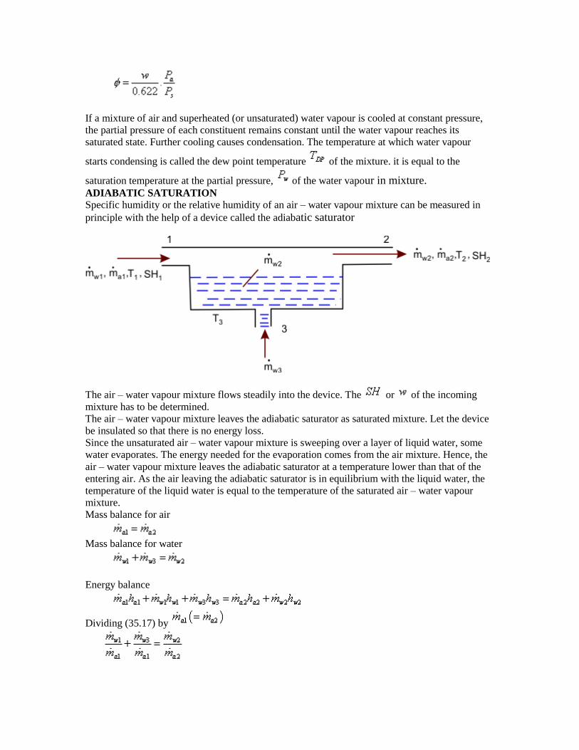
If a mixture of air and superheated (or unsaturated) water vapour is cooled at constant pressure,
the partial pressure of each constituent remains constant until the water vapour reaches its
saturated state. Further cooling causes condensation. The temperature at which water vapour
starts condensing is called the dew point temperature of the mixture. it is equal to the
saturation temperature at the partial pressure, of the water vapour in mixture. ADIABATIC SATURATION
Specific humidity or the relative humidity of an air – water vapour mixture can be measured in
principle with the help of a device called the adiabatic saturator
The air – water vapour mixture flows steadily into the device. The or of the incoming
mixture has to be determined.
The air – water vapour mixture leaves the adiabatic saturator as saturated mixture. Let the device
be insulated so that there is no energy loss.
Since the unsaturated air – water vapour mixture is sweeping over a layer of liquid water, some
water evaporates. The energy needed for the evaporation comes from the air mixture. Hence, the
air – water vapour mixture leaves the adiabatic saturator at a temperature lower than that of the
entering air. As the air leaving the adiabatic saturator is in equilibrium with the liquid water, the
temperature of the liquid water is equal to the temperature of the saturated air – water vapour
mixture.
Mass balance for air
Mass balance for water
Energy balance
Dividing (35.17) by
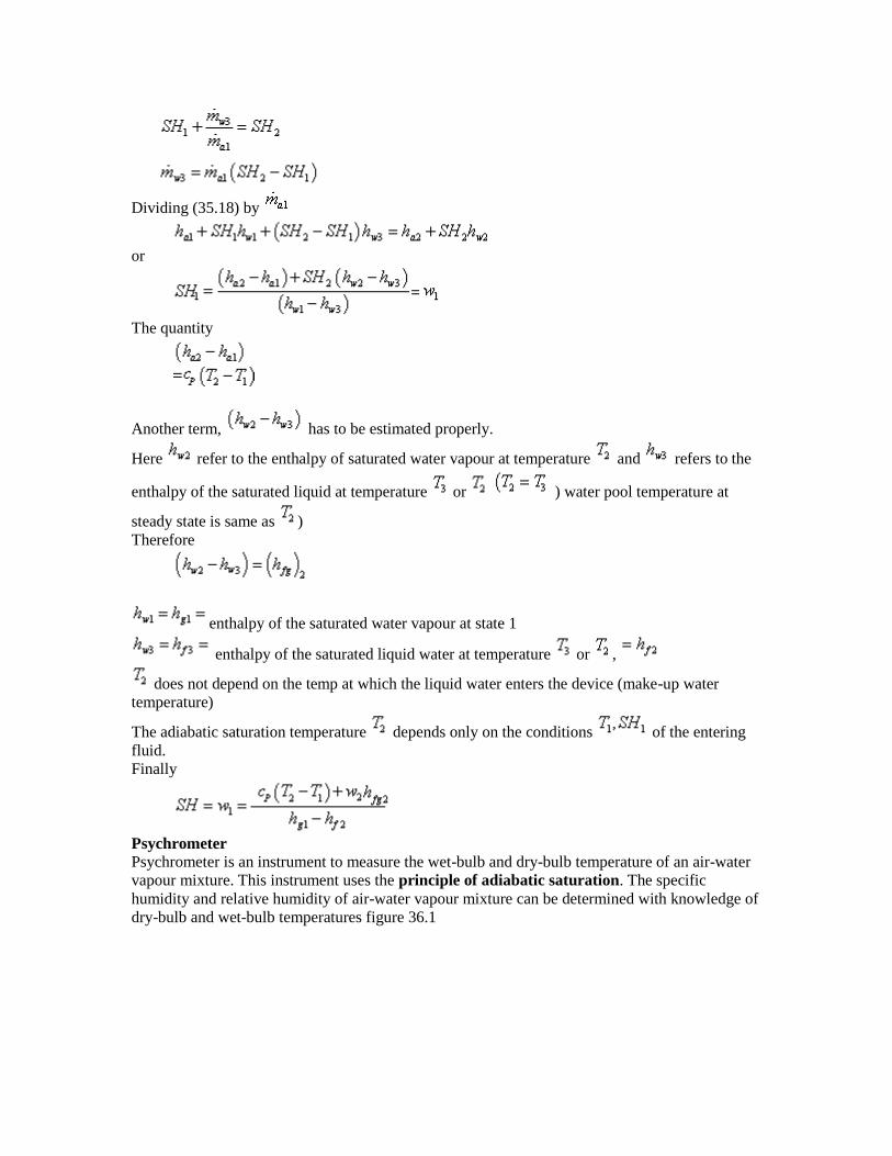
Dividing (35.18) by
or
The quantity
Another term, has to be estimated properly.
Here refer to the enthalpy of saturated water vapour at temperature and refers to the
enthalpy of the saturated liquid at temperature or ) water pool temperature at
steady state is same as )
Therefore
enthalpy of the saturated water vapour at state 1
enthalpy of the saturated liquid water at temperature or ,
does not depend on the temp at which the liquid water enters the device (make-up water
temperature)
The adiabatic saturation temperature depends only on the conditions of the entering
fluid.
Finally
Psychrometer
Psychrometer is an instrument to measure the wet-bulb and dry-bulb temperature of an air-water
vapour mixture. This instrument uses the principle of adiabatic saturation. The specific
humidity and relative humidity of air-water vapour mixture can be determined with knowledge of
dry-bulb and wet-bulb temperatures figure 36.1

The dry-bulb temperature is the temperature of the incoming mixture.
The wet-bulb temperature is the temperature of the saturated air-water vapour mixture.
For air-water vapour mixtures, the wet- bulb temperature is found to be approximately
equal to the adiabatic Saturation temperature (AST).
If and are known, & can be found out.
The enthalpy of air-water vapour mixture is expressed as
where is the enthalpy of the accompanying water vapour, and
Refer to figure 36.2
We can write
In the above equation, is vapour enthalpy, is also enthalpy of vapour. The term is
meant for enthalpy of liquid water
Also
For the above reasons, we can rewrite (36.2) as
Invoking (36.1), the above equation becomes
is the conserved property in an adiabatic saturation process. (Remember that state 2 need not
be saturated). We can further write

Where
and
If is small constant and we get
A long an adiabatic miniaturization process will remain constant
or
PSYCHROMETRIC CHART
Abscissa is the dry bulb temperature. The right hand side ordinate provides humidity
ratio. The equation shows a direct relationship between w and Pw
According, the vapour pressure can also be shown as the ordinate . The curves of
constant relative humidity are also drawn on the Psychometric Chart. On figure 36.3,
the curves are labeled as Φ = 100%, 60% etc. Psychometric Charts also gives values of
the mixture enthalpy per unit mass of dry air in the mixture. The constant wet bulb

temperature TWB lines run from the upper left to lower right of the chart. The
relationship between the wet bulb temperature and other chart quantities are provided
by using Eqn
The lines of wet bulb temperature are approximately the lines of constant mixture
enthalpy per unit mass of dry air.
Dehumidification:
When a moist air steam is cooled at constant mixture pressure to a temperature below
its dew point temperature, some condensation of water vapour would occur. Refer to
fugure 36.4 for understanding the process.
Dehumidification of air-water vapour mixture can be achieved by cooling the mixture
below its dew point temperature (path i-A-B) allowing some water to condense, and
then heating the mixture (path B-f) to the desired temperature.
Dehumidification and Cooling
For cooling the mixture, the mixture can be made to pass over the cooling coils through
which a cold refrigerant is circulated

the mixture) is sprayed into the air to be dehumidified. Then the air leaves with less
humidity at the temperature of the chilled water. Next the air is heated to the desired
temperature
These two cooling and heating processes constitute an air conditioning plant.
Humidification with Cooling
The process is same as the Adiabatic saturation except that the air may leaves
unsaturated.
Extensively used in desert coolers which is used for cooling homes in not & dry
climates. An unsaturated air-water vapour mixture is made to flow through porous pads
soaked in water (figure 36.8)
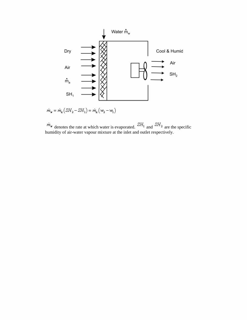
denotes the rate at which water is evaporated. and are the specific
humidity of air-water vapour mixture at the inlet and outlet respectively.

UNIT V
POWER CYCLES
Air standard Otto Cycle
Air standard Otto cycle on (a) P-v diagram (b) T-s diagram
Processes: -
0-1: a fresh mixture of fuel-air is drawn into the cylinder at constant pressure
1-2: isentropic compression
2-3: energy addition at constant volume
3-4: isentropic expansion
4-1: combustion products leave the cylinder
1-0: the piston pushes out the remaining combustion products at constant pressure
Since the net work done in processes 0-1 and 1-0 is zero, for thermodynamic analysis, we
consider the 1-2-3-4 only.
The thermal efficiency of the cycle is given by
1
21
1 Q
Q
Wnet
where Q1 and Q2 denote the energy absorbed and rejected as heat respectively.

For a constant volume process Q=U. If ‘m’ is the mass of the air which is undergoing the cyclic
process,
TmCU v
Energy is absorbed during the process 2-3
Energy is rejected during the process 4-1
Hence,
23
14
14142
23231
1
)(
TT
TT
TTmCUUQ
TTmCUUQ
v
v
For an ideal gas undergoing an isentropic process (process 1-2 and 3-4),
1Tv = constant
Hence,
1
1
2
2
1
v
v
T
T
and
1
4
3
3
4
v
v
T
T
But v1=v4 and v2=v3. Hence we get,
3
4
2
1
T
T
T
T
or 3
2
4
1
T
T
T
T
3
2
4
1 11T
T
T
T
or 3
23
4
14
T
TT
T
TT
2
1
3
4
23
14
T
T
T
T
TT
TT
Hence,
1
0
1
1
2
2
1 1111
rv
v
T
T
Where the compression ratio r0 is defined as

2
1
0v
vr
Sometimes it is convenient to express the performance of an engine in terms of Mean effective
Pressure, Pm, defined as the ratio of Net work done” to “Displacement volume”
21 vv
WPm
)( 21 vvPW m
Thermal efficiency of the ideal Otto cycle as a function of compression ratio (=1.4)
The thermal efficiency of the Otto cycle increases with the specific heat ratio, of the working
fluid.
Air standard Diesel cycle
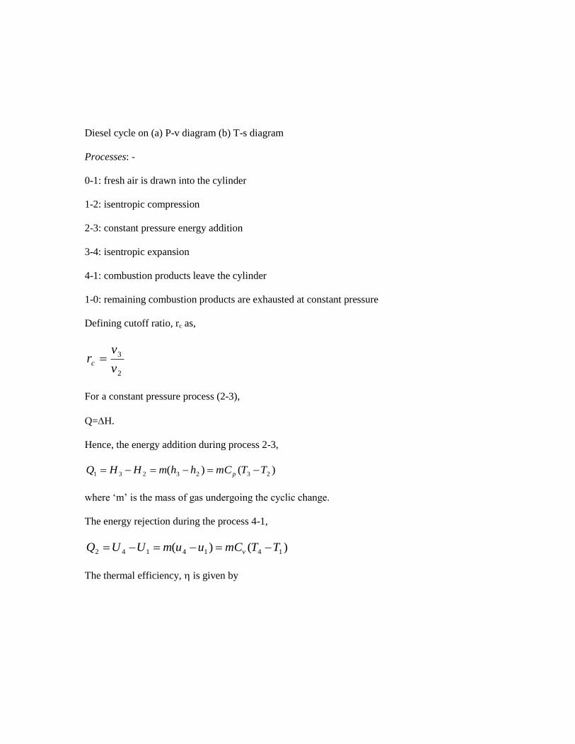
Diesel cycle on (a) P-v diagram (b) T-s diagram
Processes: -
0-1: fresh air is drawn into the cylinder
1-2: isentropic compression
2-3: constant pressure energy addition
3-4: isentropic expansion
4-1: combustion products leave the cylinder
1-0: remaining combustion products are exhausted at constant pressure
Defining cutoff ratio, rc as,
2
3
v
vrc
For a constant pressure process (2-3),
Q=H.
Hence, the energy addition during process 2-3,
)()( 2323231 TTmChhmHHQ p
where ‘m’ is the mass of gas undergoing the cyclic change.
The energy rejection during the process 4-1,
)()( 1414142 TTmCuumUUQ v
The thermal efficiency, is given by

1
1
1)(
1
)(
)()(
2
3
2
1
4
1
23
14
23
1423
1
21
T
TT
T
TT
TT
TT
TTmC
TTmCTTmC
Q
p
vp
Since the process 1-2 is isentropic,
1
0
1
1
2
2
1 1
rv
v
T
T
Since the process 4-1 is a constant volume process,
1
2
3
4
1
3
3
4
1
4
1
4
P
P
P
P
P
P
P
P
P
P
T
T
since P2=P3
The processes 1-2 and 3-4 are isentropic. Hence,
4
3
3
4
v
v
P
P
and
2
1
1
2
v
v
P
P
Hence we get,
crv
v
v
v
v
v
T
T
2
3
2
1
4
3
1
4
For the constant pressure process,
crv
v
T
T
2
3
2
3
Hence the efficiency becomes,
1
111
1
0 c
c
r
r
r
The mean effective pressure of an air standard diesel cycle is given by,

)1)(1(
1()1
0
001
r
rrrrPP cc
m
Thermal efficiency of the ideal diesel cycle as a function of compression and cutoff ratios (=1.4)
Air standard Dual cycle
Dual cycle on (a) P-v diagram (b) T-s diagram
Energy addition is in two stages: Part of energy is added at constant volume and part of the
energy is added at constant pressure
Energy added, q1
)()( 34231 TTCTTCq pv
Energy rejected, q2
)( 152 TTCq v
Thermal efficiency,
)()(
)(1
)()(
)(1
1
3423
15
3423
15
1
2
TTTT
TT
TTCTTC
TTC
q
q
pv
v
The efficiency can be expressed also in terms of,
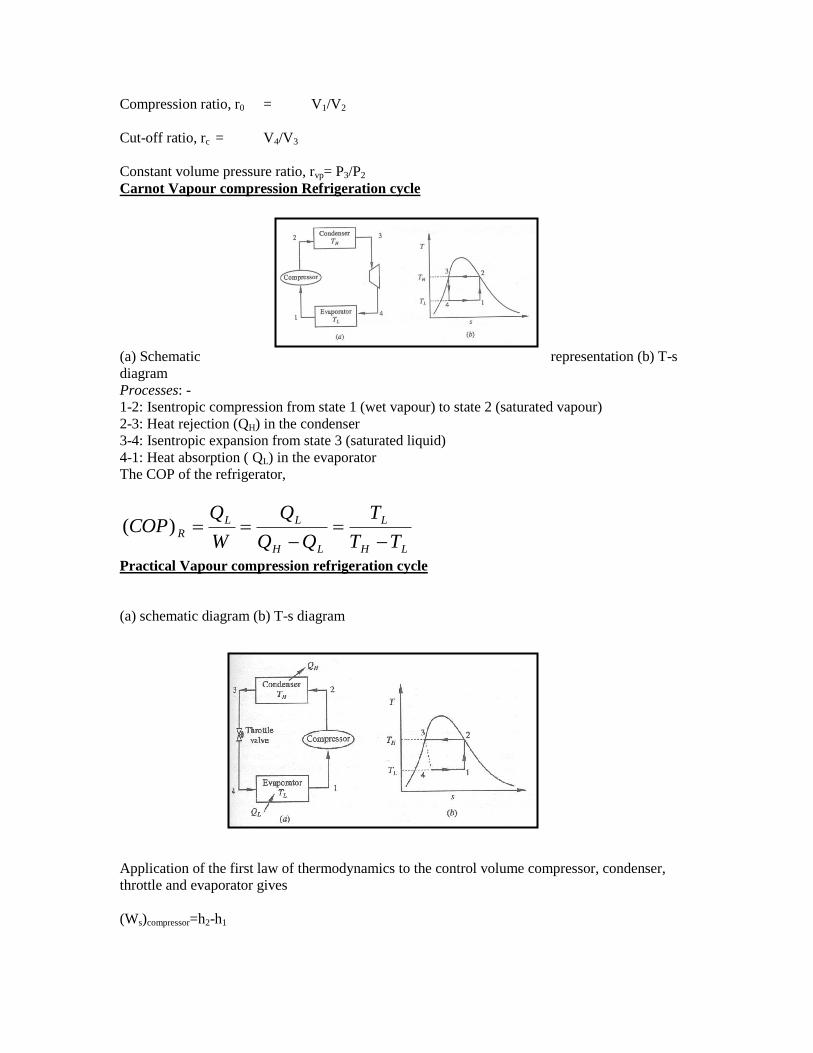
Compression ratio, r0 = V1/V2
Cut-off ratio, rc = V4/V3
Constant volume pressure ratio, rvp= P3/P2
Carnot Vapour compression Refrigeration cycle
(a) Schematic representation (b) T-s
diagram
Processes: -
1-2: Isentropic compression from state 1 (wet vapour) to state 2 (saturated vapour)
2-3: Heat rejection (QH) in the condenser
3-4: Isentropic expansion from state 3 (saturated liquid)
4-1: Heat absorption ( QL) in the evaporator
The COP of the refrigerator,
LH
L
LH
LL
RTT
T
Q
W
QCOP
)(
Practical Vapour compression refrigeration cycle
(a) schematic diagram (b) T-s diagram
Application of the first law of thermodynamics to the control volume compressor, condenser,
throttle and evaporator gives
(Ws)compressor=h2-h1

QH=h2-h3
h3=h4
and QL=h1-h4
The COP of the refrigerator is given by,
12
41)(hh
hh
W
QCOP L
R
In the ideal refrigeration cycle, the refrigerant leaves the evaporator as wet vapour.
In some cases the refrigerant leaves the evaporator as either saturated vapour or superheated
vapour.
T-s diagram for a vapour compression refrigeration cycle when the refrigerant leaves the
evaporator as (a) saturated vapour (b) superheated vapour
Gas refrigeration cycle
(a) Schematic diagram (b) T-s diagram
The simplest gas refrigeration cycle is the reversed Brayton cycle
Processes: -
1-2: isentropic compression for state 1 (atmospheric air) to state 2
2-3: energy exchange with the surrounding, air is cooled
3-4: isentropic expansion to state 4
Work obtained during the expansion process can be used to run the compressor
Work done on the compressor,
)( 1212 TTChhW pc
Work delivered by the expander,
)( 4343 TTChhW pe
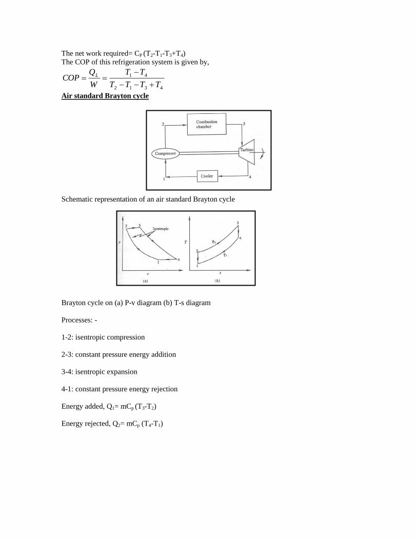
The net work required= CP (T2-T1-T3+T4)
The COP of this refrigeration system is given by,
4312
41
TTTT
TT
W
QCOP L
Air standard Brayton cycle
Schematic representation of an air standard Brayton cycle
Brayton cycle on (a) P-v diagram (b) T-s diagram
Processes: -
1-2: isentropic compression
2-3: constant pressure energy addition
3-4: isentropic expansion
4-1: constant pressure energy rejection
Energy added, Q1= mCp (T3-T2)
Energy rejected, Q2= mCp (T4-T1)

Thermal efficiency,
1
1
1
1
2
3
2
1
4
1
23
14
1
21
T
TT
T
TT
TT
TT
Q
The pressure ratio of the Brayton cycle, rp is defined as,
1
2
P
Prp
Then 1
2
4
3
P
P
P
P
The processes 1-2 and 3-4 are isentropic. Hence,
1
4
3
4
3
1
1
2
1
2
P
P
T
T
P
P
T
T
We get,
4
3
1
2
T
T
T
T
or 2
3
1
4
T
T
T
T
1
2
1
2
1 11
P
P
T
T
1
11
pr
Work delivered by the cycle is given by W=Q1
Increasing Q1 can increase work done by the cycle
Since the Turbine blade material cannot withstand very high temperature, T3 and hence Q1 is
limited
The optimum pressure ratio for fixed values of T1 and T3, for which work is maximum, is
obtained by,

11
1
11
)]()[(
)()(
1
1
1
3
1
21
3
43
1243
142321
p
p
pnet
pnet
pnet
ppnet
rTr
TmCW
T
TT
T
TTmCW
TTTTmCW
TTmCTTmCQQW
For optimum pressure ratio,
01
1
1
1
21
3
pp
pp
p
net
rTmC
rTmCdr
dW
or
1
1
21
3
p
p
rT
rT
or
)1(2
1
3 )(
prT
T
or
)1(2
1
3
T
Trp
COMPARISON OF OTTO, DIESEL AND DUAL CYCLE
• Following are the important variable factors which are used for
comparison of these cycles:
1. Compression ratio
2. Maximum pressure
3. Heat supplied
4. Heat rejected and Net work
Efficiency versus compression ratio For a given compression ratio, Otto cycle is the most efficient while the diesel cycle is
the least efficient
For the same compression ratio and the same heat input

For constant maximum pressure and heat supplied

T-S diagram

P-V DIAGRAM