Embed Size (px)
Citation preview

Thermodynamic Cycles
• Look at different cycles that approximate real processes
• You can categorize these processes several different ways• Power Cycles vs. Refrigeration• Gas vs. Vapor• Closed vs. open• Internal Combustion vs. External Combustion
Power Cycles
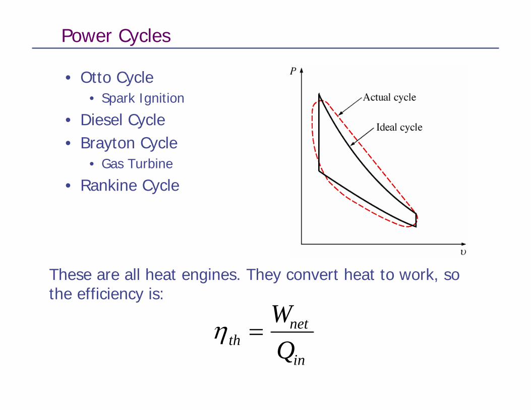
• Otto Cycle• Spark Ignition
• Diesel Cycle• Brayton Cycle
• Gas Turbine
• Rankine Cycle
η thnet
in
WQ
=
These are all heat engines. They convert heat to work, so the efficiency is:

Ideal Cycles
• We’ll be using ideal cycles to analyze real systems, so lets start with the only ideal cycle we’ve studied so far
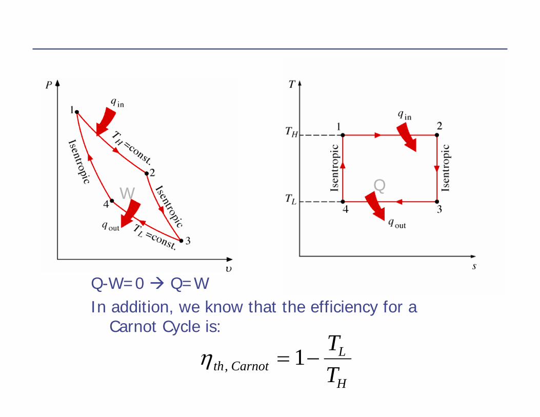
Carnot Cycle
W Q
Q-W=0 Q=WIn addition, we know that the efficiency for a
Carnot Cycle is:
η th CarnotL
H
TT, = −1

Carnot Cycle is not a good model for most real processes
• For example• Internal combustion engine• Gas turbine
• We need to develop a new model, that is still ideal
Air-Standard Assumptions
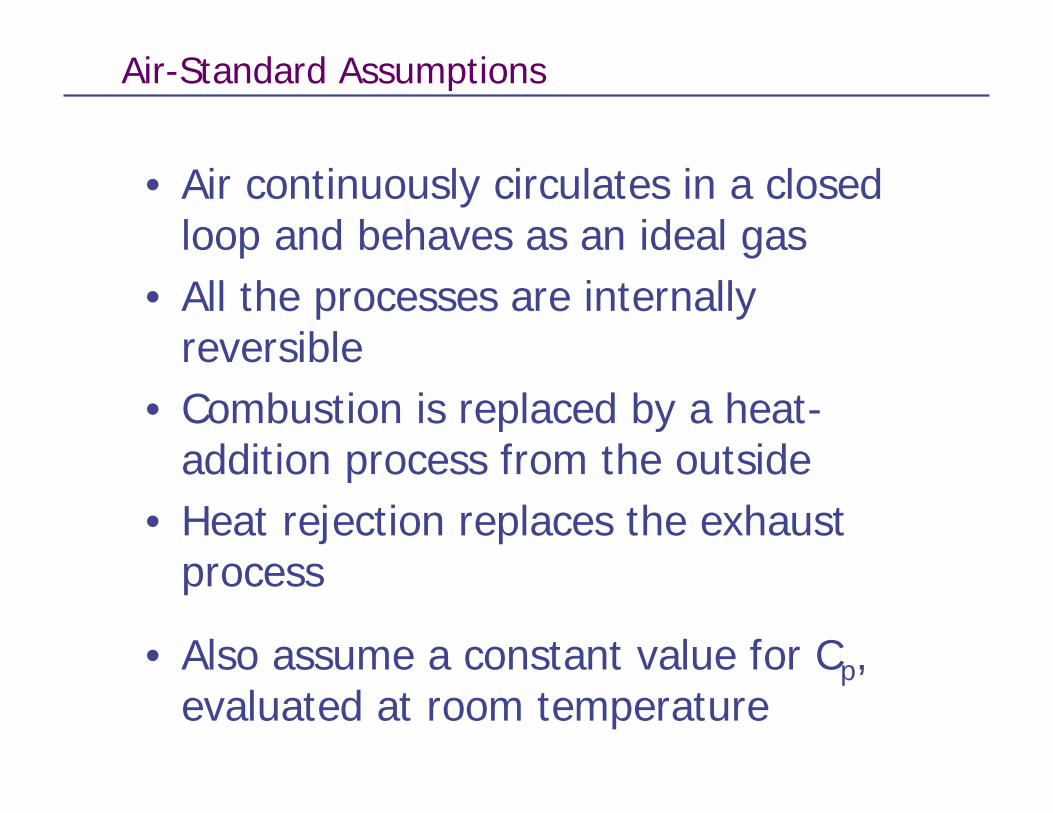
• Air continuously circulates in a closed loop and behaves as an ideal gas
• All the processes are internally reversible
• Combustion is replaced by a heat-addition process from the outside
• Heat rejection replaces the exhaust process
• Also assume a constant value for Cp, evaluated at room temperature
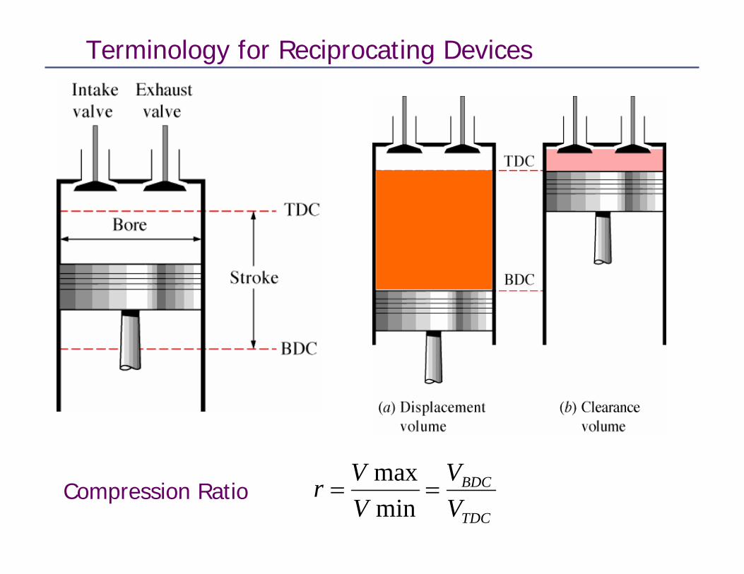
Terminology for Reciprocating Devices
r VV
VV
BDC
TDC
= =maxmin
Compression Ratio
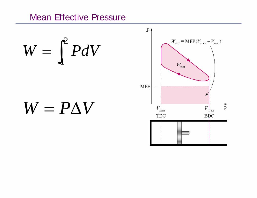
Mean Effective Pressure
∫=2
1PdVW
VPW ∆=

v
v
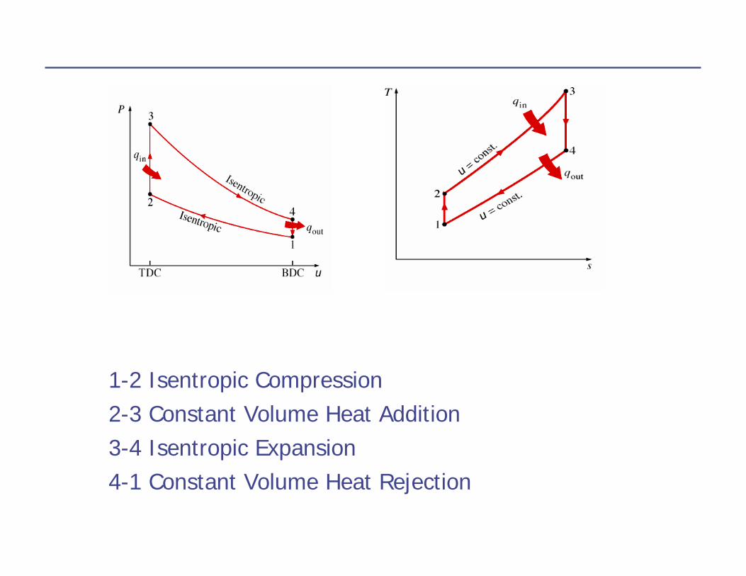
1-2 Isentropic Compression2-3 Constant Volume Heat Addition3-4 Isentropic Expansion4-1 Constant Volume Heat Rejection
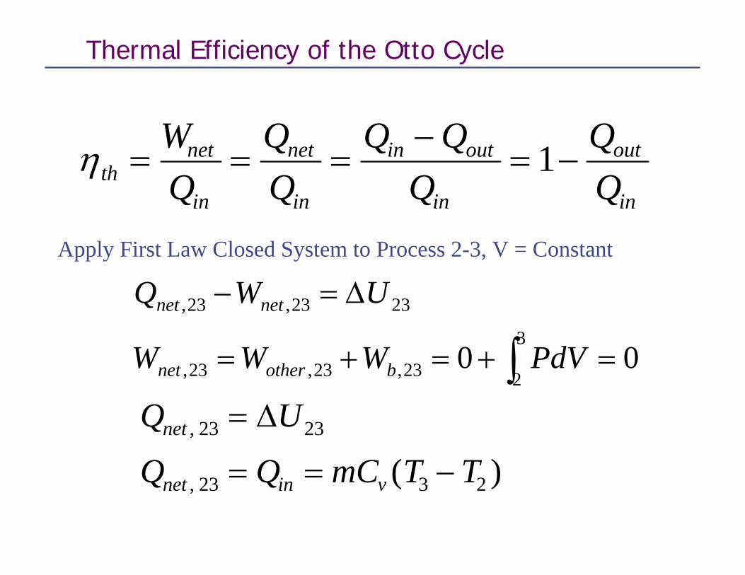
Thermal Efficiency of the Otto Cycle
η thnet
in
net
in
in out
in
out
in
WQ
Q QQ
= = =−
= −1
Apply First Law Closed System to Process 2-3, V = Constant
∫ =+=+=
∆=−3
223,23,23,
2323,23,
00 PdVWWW
UWQ
bothernet
netnet
Q U
Q Q mC T Tnet
net in v
,
, ( )23 23
23 3 2
=
= = −
∆

Apply First Law Closed System to Process 4-1,V = Constant
001
441,41,41,
4141,41,
=+=+=
∆=−
∫ PdVWWW
UWQ
bothernet
netnet
Q U
Q Q mC T T
Q mC T T mC T T
net
net out v
out v v
,
, ( )
( ) ( )
41 41
41 1 4
1 4 4 1
=
= − = −
= − − = −
∆

η th Ottoout
in
v
v
QQmC T TmC T T
,
( )( )
= −
= −−−
1
1 4 1
3 2
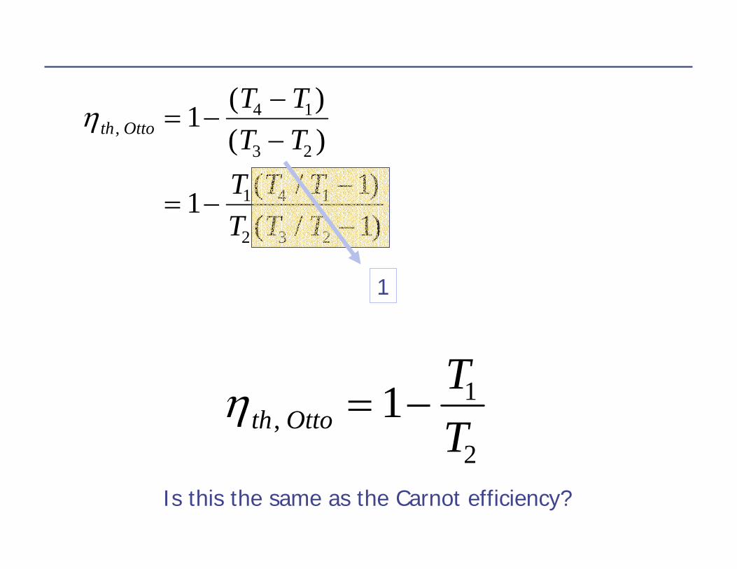
η th OttoT TT T
T T TT T T
,( )( )
( / )( / )
= −−−
= −−−
1
1 11
4 1
3 2
1 4 1
2 3 2
Recall processes 1-2 and 3-4 are isentropic, so
1
3
4
4
3
1
2
1
1
2
T and
−−
⎟⎟⎠
⎞⎜⎜⎝
⎛=⎟⎟
⎠
⎞⎜⎜⎝
⎛=
kk
vvT
vv
TT
v3 = v2 and v4 = v1
TT
TT
orTT
TT
2
1
3
4
4
1
3
2
=
=
η th OttoT TT T
T T TT T T
,( )( )
( / )( / )
= −−−
= −−−
1
1 11
4 1
3 2
1 4 1
2 3 2
1
η th OttoTT, = −1 1
2
Is this the same as the Carnot efficiency?
Efficiency of the Otto Cycle vs. Carnot Cycle
• There are only two temperatures in the Carnot cycle• Heat is added at TH
• Heat is rejected at TL
• There are four temperatures in the Otto cycle!!• Heat is added over a range of temperatures• Heat is rejected over a range of temperatures
1
1
1
2
2
1 1−
−
=⎟⎟⎠
⎞⎜⎜⎝
⎛= k
k
rVV
TT
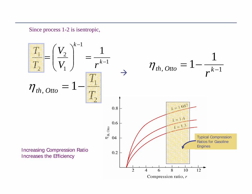
Since process 1-2 is isentropic,
η th Otto kr, = − −1 11
η th OttoTT, = −1 1
2
Increasing Compression Ratio Increases the Efficiency
Typical Compression Ratios for Gasoline Engines

Why not use higher compression Ratios?
• Premature Ignition• Causes “Knock”• Reduces the Efficiency• Mechanically need a better design
Diesel Engines
• No spark plug• Fuel is sprayed into hot compressed air
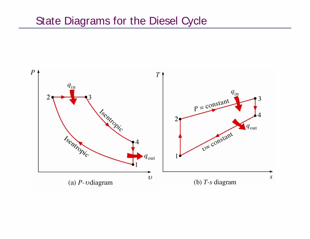
State Diagrams for the Diesel Cycle
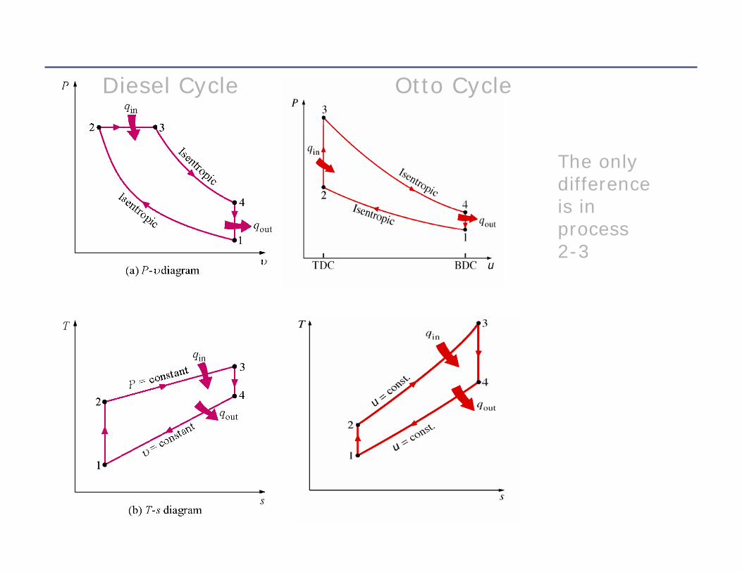
Diesel Cycle Otto Cycle
The only difference is in process 2-3

Consider Process 2-3
• This is the step where heat is transferred into the system
• We model it as constant pressure instead of constant volume
23,23, uuuwq outbin −=∆=−( )2323, TTChvPuq pin −=∆=∆+∆=
Consider Process 4-1• This is where heat is rejected• We model this as a constant v process
• That means there is no boundary work
uwq ∆=− 4141
( )4141 TTCuqq vout −=∆=−=( )14 TTCq vout −=
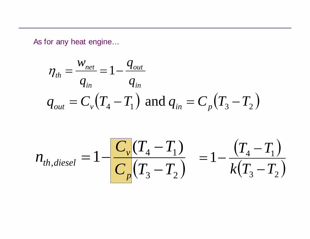
As for any heat engine…
in
out
in
netth q
qqw
−== 1η
( ) ( )2314 and TTCqTTCq pinvout −=−=
( )23
14,
)(1TTCTTCn
p
vdieselth −
−−= ( )
( )23
141TTkTT−−
−=

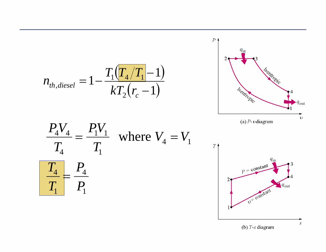
Rearrange
( )( )1
11232
141, −
−−=
TTkTTTTn dieselth
PVT
PVT
P P
TT
VV
rc
3 3
3
2 2
23 2
3
2
3
2
= =
= =
where
rc is called the cutoff ratio – it’s the ratio of the cylinder volume before and after the combustion process
( )( )1
112
141, −
−−=
cdieselth rkT
TTTn
PVT
PVT
V V
TT
PP
4 4
4
1 1
14 1
4
1
4
1
= =
=
where
kk
kk
VPVP
VPVP
3344
2211 and
=
=
( )( )1
112
141, −
−−=
cdieselth rkT
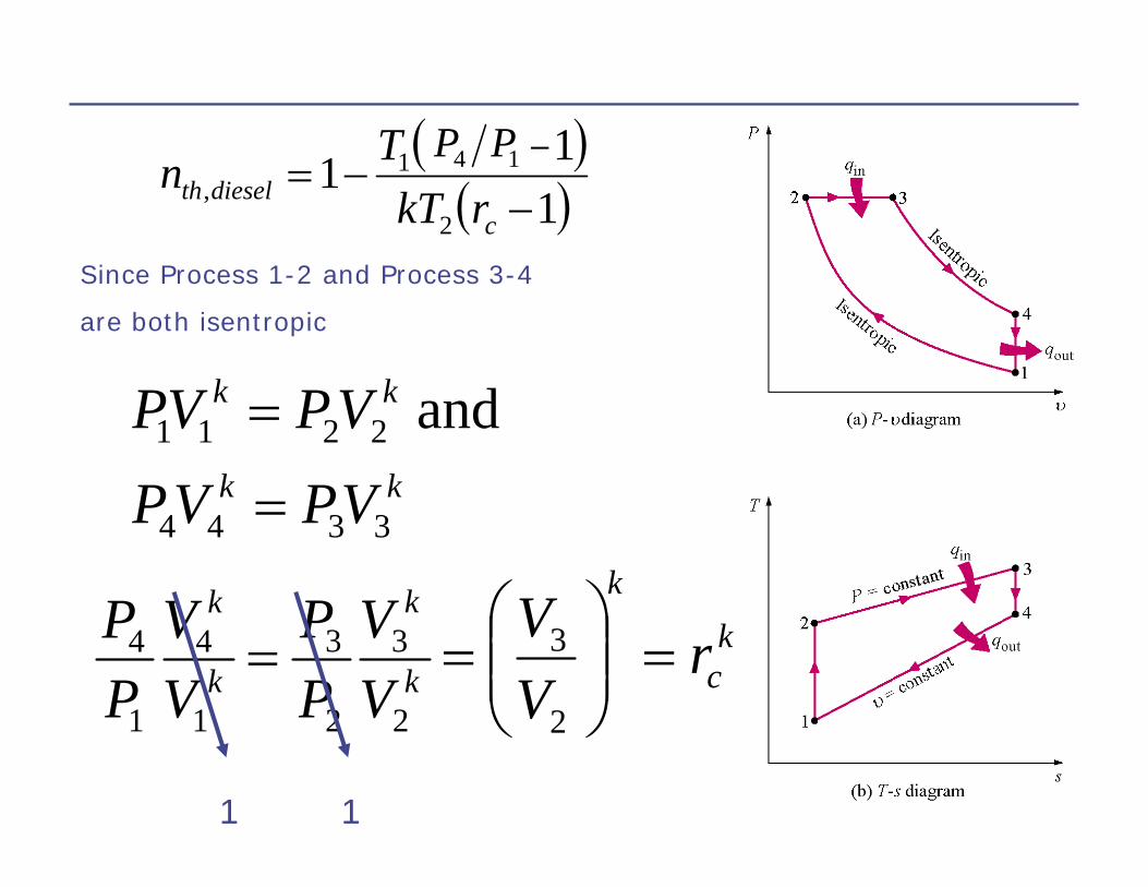
TTTn 14 PP
Since Process 1-2 and Process 3-4
are both isentropic
k
k
k
k
VV
PP
VV
PP
2
3
2
3
1
4
1
4 =
1 1
kc
k
rVV
=⎟⎟⎠
⎞⎜⎜⎝
⎛=
2
3
( )( )1
112
1, −
−−=
c
kc
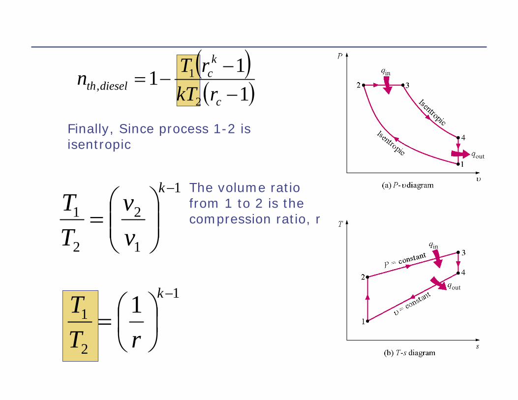
dieselth rkTrTn
Finally, Since process 1-2 is isentropic
1
1
2
2
1
−
⎟⎟⎠
⎞⎜⎜⎝
⎛=
k
vv
TT
The volume ratio from 1 to 2 is the compression ratio, r
1
2
1 1 −
⎟⎠⎞
⎜⎝⎛=
k
rTT
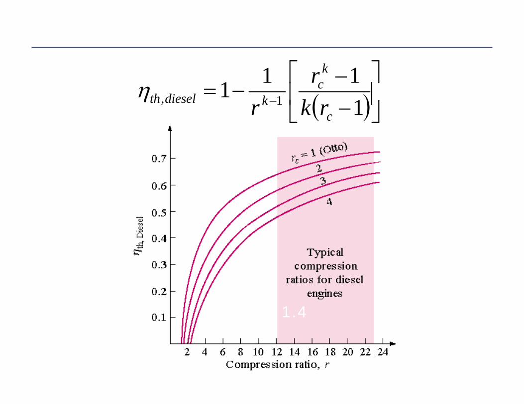
( )⎥⎦⎤
⎢⎣
⎡−−
−= − 1111 1,
c
kc
kdieselth rkr
rη
k=1.4
The efficiency of the Otto cycle is always higher than the Diesel cycle
Why use the Diesel cycle?Because you can use higher compression ratios