Embed Size (px)
Citation preview
THERMOCHEMICAL ANALYSIS OF HYDROGEN PEROXIDE
WITH APPLICATIONS TO ROCKET DESIGN
A Project Report
Presented to
The Faculty of the Department of Aerospace Engineering
San Jose State University
In Partial Fulfillment
of the Requirements for the Degree
Masters of Science
by
Robert Anthony Robles
May 2002

© 2002
Robert Anthony Robles
ALL RIGHTS RESERVED

APPROVED FOR THE DEPARTMENT OF AEROSPACE ENGINEERING
_____________________________________________________ Dr. Nikos Mourtos
_____________________________________________________ Dr. Raghu Agarwal
_____________________________________________________ Dr. Periklis Papadopoulos, NASA Ames
APPROVED FOR THE UNIVERSITY
______N/A [REPORT ONLY]____________________________

HYDROGEN PEROXIDE ROCKET ENGINES
ABSTRACT
The report provided herein documents research into hydrogen peroxide rocket propellant
and the subsequent computer modeling for its application.
A summary of an extensive literature search on hydrogen peroxide monopropellant is
provided, with references sited. The literature search on hydrogen peroxide included, but was not
limited to, propellant handling, molecular properties, dissociation through catalysis, catalyst
optimization, and history of use.
The computer model addresses the thermochemical performance of hydrogen peroxide
and suggests thruster dimensions for optimal performance. For reference, plotted data show the
anticipated performance of ground based hydrogen peroxide thruster tests.
Accuracy of the computer model was validated for hydrogen peroxide concentrations
from 70% to 98%, chamber to exit pressure ratios of 13.6 to 100, and thrust levels up to 44
Newtons. The computer model is based upon thermodynamic laws and conservation criteria,
and as such, is scalable beyond the range validated.

HYDROGEN PEROXIDE ROCKET ENGINES
- v -
TABLE OF CONTENTS
TITLE PAGE ….……………………………………………………………. i
ABSTRACT ….……………………………………………………………. iv
NOMENCLATURE ….……………………………………………………. vii
INTRODUCTION ….………………………………………………………. 1
Purpose ….………………………………………………………..….. 1
Background and Rationale for Work ….………………………….….. 1
Subject ….………………………………………………………...….. 1
Literature Search ….………………………………………………….. 2
METHOD ….……………………….……………………………………….. 2
Analysis Modeling ….……………………………………………….. 2
Thermochemistry. ….……………….……………………….. 3
Theoretical Rocket Performance. ….…………………...…….. 4
Preliminary Thruster Design. ….…….……………………….. 4
Numerical Modeling ….…………………………………………….... 7
RESULTS AND DISCUSSION ….………………..…………….………….. 8
Thermochemistry ….………………………………….….………….. 8
Theoretical Rocket Performance ….…….……………….….……….. 12
Preliminary Thruster Design ….………………..…...……………….. 14
Final Output ….…………………………………………………..….. 15
Optimization ….…………………………………………………..….. 16
CONCLUSION ….…………………..…………………………………..….. 19
What was learned ….……………………………………………..….. 19
Recommended Future Work ….………………..…………………….. 20
REFERENCES ….……………….….……………………………………….. 21
APPENDIX 1 ….……………….….……………………………… Appendix 1
APPENDIX 2 ….……………….….……………………………… Appendix 2
APPENDIX 3 ….……………….….……………………………… Appendix 3
APPENDIX 4 ….……………….….……………………………… Appendix 4
HYDROGEN PEROXIDE ROCKET ENGINES
- vi -
LIST OF TABLES
Table 1 Results Comparison of Theoretical Rocket Performance ………….. 12
Table 2 Results Comparison of Preliminary Thruster Design .…………….. 14
Table 3a Example Thruster Requirements ...…………….………………….. 15
Table 3b Theoretical Rocket Performance ...…………….………………….. 15
Table 3c Nozzle Dimensions Based Upon Theoretical Performance .…….. 15
Table 3d Chamber Dimensions Based Upon Chosen Configuration ...…….. 16
Table 3e Predicted Thruster Performance ….…………..………………….. 16
LIST OF FIGURES
Figure 1 Chemical Rocket Preliminary Design Flow Chart ……………….. 3
Figure 2 Nozzle Dimensions, Low Thrust Application ..………………….. 5
Figure 3 Empirically Determined Thruster Dimensions .…………….…….. 6
Figure 4 Computer Program Flow Diagram ….……………………….…….. 7
Figure 5 NASA’s CEA and Masters Project Results Comparison ….……... 10
Figure 6 Hydrogen Peroxide Reaction Products ….…………………….….. 11
Figure 7 Concentration Effects on Hydrogen Peroxide Performance ….…… 12
Figure 8 Chamber Pressure Effect on Hydrogen Peroxide Performance …... 14

HYDROGEN PEROXIDE ROCKET ENGINES
- vii -
NOMENCLATURE Parameter Description
Mr Molecular weight of reactants Mavg Average molecular weight of products %H2O2 Concentration of hydrogen peroxide (by volume) within water nr Number of moles of reactants np Number of moles of products ρ Density Cpavg Average Specific Heat of Products R Gas constant γ Specific Heat Ratio of Products ΔRH Heat of reaction ΔfH Heat of formation Q Heat released by reaction g Acceleration of gravity at sea level Tc Chamber Temperature Isp Specific Impulse m i Ideal mass flow rate m Mass flow rate (predicted) Ft Thrust (theoretical) T Thrust (predicted) Pc, p1 Chamber pressure Pe, p2 Exit pressure Vt Throat velocity V2 Exit velocity Cf Coefficient of Thrust c* Characteristic Velocity κ Catalyst load factor α Nozzle half-angle β Contraction angle ε Expansion ratio At, Area of throat Ae Area of nozzle exit Ac Area of chamber/catalyst Li Length of chamber, pre-catalyst Lc Length of catalyst in chamber Lo Length of chamber, post-catalyst λ Nozzle correction factor ζv Velocity correction factor ζd Discharge correction factor
ζF Thrust correction Factor

HYDROGEN PEROXIDE ROCKET ENGINES Page 1
INTRODUCTION
Purpose
The report contained herein partially fulfills the requirements for an Aerospace
Engineering (A.E.) Masters Degree at San Jose State University (SJSU). The A.E. program
requires completion of a masters project with documented analyses and results. The masters
project demonstrates the student’s understanding of the theoretical concepts obtained through
coursework material in an area of study.
Background and Rationale for Work
The Aerospace Engineering student’s area of concentration is space propulsion. An
aptitude for chemistry led the student to focus upon chemical rocket propulsion for the masters
project.
Upon completion of advanced space propulsion and physical chemistry courses, the
student decided that the topic of the project would include thermochemistry. Hydrogen peroxide
was chosen as the propellant to be analyzed, because of its properties as a versatile “green”
monopropellant. Upon advisement of a review committee professor, the student extended the
scope of the project to include the research and efforts involved with preliminary thruster design.
Subject
The subject of the report is the thermochemical analysis of hydrogen peroxide
monopropellant with design optimization for rocket engines in low thrust applications.
Supported by research, the entire subject is simulated through a computer model. Validity of the
computer model is provided, by comparison to industry standards and published literature.

HYDROGEN PEROXIDE ROCKET ENGINES Page 2
Literature Search
The majority of knowledge pertaining to thermochemistry and chemical rocket
propulsion was obtained through coursework at SJSU. The specific details of hydrogen peroxide
in its application as a monopropellant, was supported with published literature from the industry.
Published literature on hydrogen peroxide and its use as a monopropellant was obtained
from SJSU and Stanford libraries, AIAA (American Institute of Aeronautics and Astronautics)
Journals, Hydrogen Peroxide Conference bindings, the Teltech® technical paper publishing firm,
and other credible sources.
The literature obtained and reviewed, are identified within the References section of this
report. The Results section identifies the application of the literature towards the computer
analysis performed.
A summary of findings from the literature search that is pertinent to hydrogen peroxide,
but was not directly used by the computer program, is available within Appendix 4. The findings
are categorized into handling requirements, performance, and history of use.
METHOD
Analysis Modeling The first step to the development of the computer program was the generation of a flow
chart. The flow chart of Figure 1 includes the key characteristics of input, processing, and
output. The steps of Figure 1 support the purpose of the masters project, as described within the
Introduction.

HYDROGEN PEROXIDE ROCKET ENGINES Page 3
Figure 1 Chemical Rocket Preliminary Design Flow Chart
Two iterations of the computer program were required to achieve the full process and
output of the flow diagram. The iterations are identified as the first computer simulation and
final computer simulation.
The goal of the first computer simulation was to confirm a functional program with all
points of errors removed. The first stage of computer simulation was based upon reasonable
assumptions to simplify the code.
The goal of the final computer simulation was to achieve maximum accuracy in the
results, and provide a complete set of output for preliminary thruster design.
The three major stages of the computer program are Thermochemistry, Theoretical
Rocket Performance, and Preliminary Thruster Design. The following subsections, which
coincide with the three major stages, identify the pertinent assumptions that are used within the
computer program.
Thermochemistry.
It was assumed that the reaction for the dissociation of hydrogen peroxide was
stoichiometric. According to Sercel (2000), Yamada and Nisioka (1965), and SJSU Advanced
Space Propulsion Course Notes, the products of dissociation are water vapor and oxygen.
H2O2 H2O + ½ O2
Chemical Propellant Properties
Thermochemical Analysis
Theoretical Rocket Performance
Thruster Dimensions
(1)

HYDROGEN PEROXIDE ROCKET ENGINES Page 4
The stoichiometric assumption was enhanced to better describe the concentration of
hydrogen peroxide (by weight).
a H2O2 (liquid) + b H2O (liquid) c H2O (vapor) + d O2 (gas)
The mole values of the products (c, d) and reactants (a, b) were calculated based upon
molecular weight and the given concentration by weight. Details of the calculation method are
available within Appendix 2.
Theoretical Rocket Performance.
With respect to the thrust chamber, it was assumed that the system was adiabatic, and all
available energy released from the dissociation was transferred entirely into the products (Hill,
1992). Flow through the throat and nozzle was assumed to be quasi-one dimensional frozen flow
(Sutton, 2001). The assumptions provide sufficient accuracy for preliminary thruster design per
Sutton (2001).
To account for actual (non-ideal) thruster performance, established correction factors
(Sutton, 2001) were utilized. A description of the correction factors, and their implementation is
available within the Results section, and Appendix 1 and 2.
Preliminary Thruster Design.
The design of a monopropellant thruster, which includes the chamber, throat, and nozzle,
is partially dependant upon empirical data. The first computer simulation addressed the non-
empirical data, which was limited to the throat and nozzle.
(2)
(3)

HYDROGEN PEROXIDE ROCKET ENGINES Page 5
Figure 2 Nozzle Dimensions, Low Thrust Application
Based upon nozzle theory (Sutton, 2001; Hill, 1992), the throat area (At) and exit area
(Ae) are derived from the properties of the gaseous products (temperature, pressure, molecular
weight, and specific heat), the laws of thermodynamics, and conservation criteria. The resultant
equations are shown within Appendix 1 and 2.
For low thrust applications and manufacturing simplicity, the computer program models a
conical nozzle (Sutton, 2001; Hill, 1992, Huzel & Huang, 1992). Loss to exhaust momentum,
based upon the nozzle half angle (α), is calculated through λ (nozzle correction factor). The
equation for λ, and the application to Thrust (T), is provided within Appendix 1 and 2.
The final computer simulation derived the remainder of internal thruster dimensions that
were dependant upon empirical data. Figure 3 identifies the dimensions from the final computer
simulation.
Ae
At
α
Catalyst Pack
Gas Generator

HYDROGEN PEROXIDE ROCKET ENGINES Page 6
Figure 3 Empirically Determined Thruster Dimensions
Sutton (2001) identified that the throat contour, or radius of curvature (Rt), is not critical
for performance, and “any radius is usually acceptable.” The designer is suggested to define a
radius that meets manufacturability requirements, and the angles of α (nozzle half-angle) and β
(contraction angle).
Sutton (2001) also provided that the contraction angle may approach 90 degrees without
significant performance loss. Thus, the designer should focus upon the requirements of Lo
(chamber length, post-catalyst).
Relative to the chamber, special considerations for hydrogen peroxide monopropellant
thrusters were incorporated into the program. Three stages to the chamber exist. The first stage
(Li) is where liquid hydrogen peroxide is introduced. The second stage is the catalyst, which is
assumed to completely dissociate the hydrogen peroxide per Equation (2). The third stage (Lo) is
where the gaseous products are accelerated into the throat. The dissociation of hydrogen
peroxide is completed within the catalyst, and there is no combustion occurring within Lo.
Hence, the length of the chamber after the catalyst (Lo) should be minimized to limit heat
transfer and starting transients (Davis & McCormick, 1960).
β
Lc
Ac
Rt
Li Lo

HYDROGEN PEROXIDE ROCKET ENGINES Page 7
The cross sectional area of the catalyst (Ac), which coincides with the chamber, and the
length of the catalyst (Lc), are entirely dependent upon the catalyst design. For samarium oxide
coated silver screen catalysts, the cross sectional area may be calculated per Davis and
McCormick (1960). The equation for Ac is available within Appendix 1 and 2.
The length (Li) of the chamber between the flow orifice and the catalyst is entirely
dependant upon the catalyst design. Li must be of sufficient length to allow for uniform
hydrogen peroxide flow through the catalyst. However, to limit start-up transients, the pre-
catalyst length (Li) should be minimized (Davis and McCormick, 1960).
Numerical Modeling - Equation Derivation and Implementation
Taken from the steps of the analysis model, a detailed flow diagram of the computer
program is provided within Figure 4.
Figure 4 Computer Program Flow Diagram
Chemical Propellant Properties
ΔfH, Mr, ρ, %H2O2
Design Criteria Pc, Pe
Thermochemical Analysis ΔRH, Q, nr, np, Mavg, Cpavg,
R, γ, Tc
Theoretical Rocket Performance
V2, Vt, Cf, c*, Isp
Design Criteria Ft, κ, α
Thruster Throughput m i
Estimated Losses λ, ζv, ζd, ζF
Predicted Performance m , T, Isp
Thruster Dimensions ε, At, Ae, Ac

HYDROGEN PEROXIDE ROCKET ENGINES Page 8
Given the assumptions previously identified within the analysis model, the equations for
the program were derived or taken directly from textbooks (with confirmation of correct
assumptions). The equations were sequenced to provide the desired output. The individual
equations and the stages of the computer analysis are provided in Appendix 1.
The computer analysis was performed through Matlab®. Appendix 2 contains the final
computer program.
The method employed to validate each stage of the computer program was to compare
the output to published literature or other industry standards. The details of all validation
techniques are provided within the Results section.
RESULTS AND DISCUSSION
Thermochemistry
The thermochemical results of the first simulation identified that the stoichiometric
assumption (Equation 2) provided accurate data, as compared to an industry standard (Gordon &
McBride, 1996) and published literature (Yamada & Nisioka, 1965). The thermochemical
criteria used to determine accuracy, included the chamber temperature and mole fraction of the
products.
The Industry standard (Gordon & McBride, 1996) used is the National Aeronautics and
Space Administration’s (NASA’s) Chemical Equilibrium with Applications (CEA) program,
which has been publicly available in various forms since 1967. Figure 5 provides a comparison
between CEA and the masters project (MP). The thermochemical deviations noted between
CEA and MP are 0.0% on average.

HYDROGEN PEROXIDE ROCKET ENGINES Page 9
The thermochemical results pertaining to reaction equilibria were also in agreement with
a physical understanding of the process. Minimization of Gibbs free energy, which coincides
with maximization of Entropy for the reaction (Atkins, 1999; Levine, 1995; McQuarrie & Rock,
1991), would occur when the aqueous hydrogen peroxide decomposes fully into gaseous (more
chaotic) products. Additionally, the decomposition temperature (Figure 4) was substantially
below 2300K, which is an approximate point that products tend to dissociate further (Course
Notes, SJSU Advanced Space Propulsion, 1999). Thus, the heat of reaction is based solely upon
the heats of formation of hydrogen peroxide, water, and oxygen, in their respective states.
The accuracy obtained through the simplified stoichiometric assumption – including
concentration effects – eliminated the need for calculating equilibria through usage of reaction
rates, and the consideration of all reaction steps.

HYDROGEN PEROXIDE ROCKET ENGINES Page 10
Figure 5 NASA’s CEA and Masters Project Results Comparison
The effect of hydrogen peroxide concentration on the mole fraction of the products was
analyzed per Figure 6. As the concentration of hydrogen peroxide increases over water, the
amount of O2 in the products increases proportionally. This coincides with the balanced reaction
(Equation 2) described within the Method section.
HYDROGEN PEROXIDE MONOPROPELLANT THRUSTERCOMPARISON - NASA's CEA vs. MP (Student Masters Project)
Weight Pressure MP MP CEA CEA DifferencePc Pe Percentage Ratio Mole Fract Mole Fract Mole Fract Mole Fract Product
Run (psia) (psia) H2O2 Pc/Pe H2O(vapor) O2(gas) H2O(vapor) O2(gas) Mole Fract1 300 14.7 0.70 20.4 0.7835 0.2165 0.7835 0.2165 0.0%2 300 14.7 0.78 20.4 0.7540 0.2460 0.7540 0.2460 0.0%3 300 14.7 0.87 20.4 0.7194 0.2806 0.7194 0.2806 0.0%4 300 14.7 0.95 20.4 0.6874 0.3126 0.6874 0.3126 0.0%5 300 14.7 0.98 20.4 0.6750 0.3250 0.6750 0.3250 0.0%6 200 14.7 0.70 13.6 0.7835 0.2165 0.7835 0.2165 0.0%7 200 14.7 0.98 13.6 0.6750 0.3250 0.6750 0.3250 0.0%8 200 5.0 0.70 40.0 0.7835 0.2165 0.7835 0.2165 0.0%9 200 5.0 0.98 40.0 0.6750 0.3250 0.6750 0.3250 0.0%
10 250 2.5 0.70 100.0 0.7835 0.2165 0.7835 0.2165 0.0%11 250 2.5 0.98 100.0 0.6750 0.3250 0.6750 0.3250 0.0%
MP CEA Difference MP CEA Difference MP CEA DifferenceRun Tc Tc Tc Ae/At Ae/At Ae/At Isp Isp Isp
1 537.0 536.0 0.2% 3.147 3.124 0.7% 96.70 96.76 -0.1%2 736.7 735.2 0.2% 3.187 3.167 0.6% 112.68 113.04 -0.3%3 951.3 956.3 -0.5% 3.246 3.228 0.6% 127.44 128.50 -0.8%4 1151.3 1151.9 -0.1% 3.271 3.282 -0.3% 139.17 140.49 -0.9%5 1224.7 1225.5 -0.1% 3.284 3.301 -0.5% 143.18 144.66 -1.0%6 537.0 536.0 0.2% 2.439 2.429 0.4% 92.00 92.08 -0.1%7 1224.7 1225.5 -0.1% 2.527 2.548 -0.9% 135.97 137.33 -1.0%8 537.0 536.0 0.2% 4.890 4.835 1.1% 103.15 103.17 0.0%9 1224.7 1225.5 -0.1% 5.166 5.149 0.3% 153.15 154.75 -1.0%
10 537.0 536.0 0.2% 9.132 8.973 1.7% 109.92 109.86 0.1%11 1224.7 1225.5 -0.1% 9.814 9.610 2.1% 163.78 165.36 -1.0%
AVERAGE 0.0% 0.5% -0.6%

HYDROGEN PEROXIDE ROCKET ENGINES Page 11
Figure 6 Hydrogen Peroxide Reaction Products
The amount of heat released in the reaction was analyzed through observation of the
chamber temperature. A survey of the chamber temperature versus hydrogen peroxide
concentration is provided within Figure 7. The chamber temperature is representative of the
temperature of the products, assuming adiabatic conditions. The results of Figure 7 correlate
well with a similar figure (low resolution, hand drawn data points) published within Yamada and
Nisioka (1965).

HYDROGEN PEROXIDE ROCKET ENGINES Page 12
Figure 7 Concentration Effects on Hydrogen Peroxide Performance Theoretical Rocket Performance
Within the limits of hydrogen peroxide concentrations of 70% to 98%, the simulation
results were found to be accurate versus an Industry Standard (Gordon & McBride, 1996; Figure
5) and published literature (Quintana, 1999; Table 1).
Table 1 Results Comparison of Theoretical Rocket Performance
Parameter Reference*
Value Computer Sim Value
Deviation
H2O2 Concentration 90% 90% 0% Pressure Ratio, Pc/Pe undefined 30.6 N/A Chamber Temp 1029 K 1029 K 0 K Specific Impulse, Isp 138 sec 138 sec 0 sec
* Reference: Quintana, 1999

HYDROGEN PEROXIDE ROCKET ENGINES Page 13
The deviation of specific impulse (Isp) that exists between CEA and MP (Figure 5) is less
than 1% on average. NASA’s CEA program and the masters project computer program were
extensively reviewed for differences in calculation. Each program utilizes a different method of
solution, and are inherently complex. The deviation is primarily attributed to (1) use of constants
for unit conversions, and (2) reference data for the enthalpy of products. In regards to the later
observance, NASA CEA and MP use different source data for the enthalpy of products. Source
data for MP are detailed within Appendix 2. Source data of CEA is provided within Gordon and
McBride (1996).
Appendix 3 provides sample output from the NASA CEA program.
Theoretical rocket performance was evaluated for various concentrations of hydrogen
peroxide rocket propellant. Figure 7 describes the anticipated performance of ground based (exit
pressure, Pe = 14.7 psia) thruster tests, given a chamber pressure (Pc) of 300 psia.
Figure 8 examines the effects of chamber pressure on thruster performance. The results
of Figure 8 identifies that at a chamber pressure of 450 psia, the Isp approaches 150 seconds.
According to published literature (Sercel, 2000; Yamada & Nisioka, 1965), the specific impulse
of hydrogen peroxide is commonly quoted as 150 seconds.

HYDROGEN PEROXIDE ROCKET ENGINES Page 14
Figure 8 Chamber Pressure Effect on Hydrogen Peroxide Performance
Preliminary Thruster Design
Computer simulation accuracy was determined by comparing the output to NASA’s CEA
program (Figure 5) and published literature (Haag, 1998; Table 2). Dimensional and
performance data of an actual hydrogen peroxide thruster was provided by Haag (1998). After
scaling the thrust to match the observed results, the throat diameter exhibited direct correlation
with the computer simulation.
Table 2 Results Comparison of Preliminary Thruster Design
Parameter Reference*
Value Computer Sim
Value Deviation
Mass Flow Rate 4.9 g/sec 4.9 g/sec 0.0 g/sec Throat Diameter 1.5 mm 1.5 mm 0.0 mm Chamber Temp 961 Kelvin 1005 Kelvin 44 Kelvin
* Reference: Haag, 1998

HYDROGEN PEROXIDE ROCKET ENGINES Page 15
The differences in chamber temperature results of Table 2 are attributed to the
measurement devices and heat transfer loss (non-adiabatic).
Final Output
The culmination of the three major stages of the computer program (thermochemistry,
theoretical rocket performance, and preliminary thruster design) provided the tools necessary to
develop a thruster.
Example output based upon the requirements of Table 3a, are provided within Tables 3b
through Table 3e.
Table 3a Example Thruster Requirements
Parameter Description Value Pc Chamber Pressure 250 psia Pe Exit Pressure 14.7 psia %H2O2 Concentration of H2O2 85 % Catalyst Silver Mesh 40-40 (samarium
oxide coated) T Design thrust 10 lbf (44 N)
Table 3b Theoretical Rocket Performance
Isp Theoretical Specific Impulse 121 sec Tc Chamber Temperature 898 K c* Characteristic Velocity 876 m/sec CF Coefficient of Thrust 1.361 m Mass flow rate 37 gram/sec ε Expansion Ratio 2.887
Table 3c Nozzle Dimensions Based Upon Theoretical Performance Parameter Description Reference Figure Value Ae Exit Area of Nozzle Figure 2 0.5415 cm2 At Throat Area Figure 2 0.1876 cm2 α Nozzle Half-angle Figure 2 12º

HYDROGEN PEROXIDE ROCKET ENGINES Page 16
Table 3d Chamber Dimensions Based Upon Chosen Configuration
Parameter Description Reference Figure Value β Nozzle Half-angle Figure 6 55º Ac Chamber cross-section area Figure 6 3.151 cm2
Table 3e Predicted Thruster Performance
Parameter Description Reference Value λ Nozzle Correction Factor Hill (1992) 0.989 ζV Est. Velocity Correction Factor Sutton (2001) 0.96 ζd Est. Discharge Correction Factor Sutton (2001) 1.00 ζF Est. Thrust Correction Factor Sutton (2001) 0.96 T Predicted Thrust 9.5 lbf (41.8 N) Isp Predicted Isp 115 sec
The empirically derived values of Li, Lc (Figure 6) were not included in the program
output. The values are to be determined through experiment, with consideration of the
previously addressed limitations (see Method section).
The computer simulation did not address the external dimensions of the thruster, as they
are dependant upon thruster design and assembly. The thruster walls must be of the appropriate
materials to withstand the applied temperatures and pressures (Sutton, 2001; Huzel & Huang,
1992).. Reactivity of materials with hydrogen peroxide must also be considered (Pottinger,
2001; Whitehead, 1998; Bruce, 2001).
Optimization
As detailed within the report, further enhancement to the computer program is possible.
Enhancement would be achievable through optimization to one or all of the three major stages of
the program (Thermochemistry, Theoretical Rocket Performance, and Preliminary Thruster
Design).

HYDROGEN PEROXIDE ROCKET ENGINES Page 17
Optimization to the thermochemical portion of the computer program, are summarized
below:
• Heat Transfer - the program assumes an adiabatic reaction, which is not
representative of actual conditions.
o Optimization may be added to the model by accounting for heat transfer to the
catalyst support structure and the walls of the thruster.
• Chemical Reactants – the chemical reaction did not account for reactants beyond
hydrogen peroxide and water.
o If significant levels of contaminate are present within the propellant, feed
system, or chamber, it would be optimal to model the effects of these
impurities.
• Reaction Products – the products of dissociation were gaseous oxygen and water. In
a more rigorous sense, negligible traces of additional compounds or elements would
be present.
o At high concentrations (> 90%) of hydrogen peroxide aqueous solutions, the
dissociation would also result in a negligible amount of OH, and other
gaseous products. An optimal model would account for all products.
o During the reaction through the catalyst, the entirety of hydrogen peroxide
will not dissociate. The completeness of dissociation is dependant upon the
catalyst and operational conditions. An optimal model would account for
incomplete dissociation.

HYDROGEN PEROXIDE ROCKET ENGINES Page 18
Optimization to the theoretical rocket performance stage of the computer program, are
summarized below:
• Frozen Flow – the computer model assumes frozen flow conditions.
o The actual conditions of the thruster may experience further dissociation or re-
association of the products. Additionally, the water vapor may condense
within the flow region of the nozzle, for low concentration (<85%) hydrogen
peroxide and low exit pressures. An optimal model would eliminate the
frozen flow assumption.
• Heterogeneous Working Substance – impurities within the exhaust gases would affect
the average exhaust velocity of the engine.
o It would be optimal to account for all impurities and the effect to average
exhaust velocity and momentum.
Optimization to the preliminary thruster design stage of the computer program primarily
concerns the catalyst pack. Additional areas of thruster design optimization (e.g., bell shaped
nozzle) are adequately addressed within Sutton (2001), Huzel and Huang (1992), and Hill
(1992).
The catalyst is paramount to hydrogen peroxide thruster design. An optimal catalyst
configuration (Bowker, 1998; Rusek, 1995; Rusek & Anderson, 1998; Whitehead, 1998; Davis
& McCormick, 1960; Sellers, Brown, & Paul, 1998) should seek the following seven items:
1. High product yield per unit time
2. Minimal pressure drop
3. Low temperature engine starts, pulsed or steady state
4. Structurally capable for all loads - CTE mismatches, etc.

HYDROGEN PEROXIDE ROCKET ENGINES Page 19
5. Maintains phase without melting of fusing
6. High total throughput capability
7. Maintains consistent performance over life
Depending upon the mission criteria, additional areas of consideration may arise.
CONCLUSION What was learned
As detailed within the introduction, the report was performed for fulfillment of the
requirements for a Masters Degree in Aerospace Engineering at San Jose State University. The
primary goal of the report was to demonstrate that the student was capable of applying the
theoretical concepts from coursework. The student achieved this goal by (1) supporting
coursework material with extensive research on chemical propellants, (2) creating a computer
program that used raw chemical information to generate a preliminary thruster design, and (3)
employing various means to validate results.
As desired by the student whom completed the project, an enhanced understanding of
physical chemistry (rates of reaction, heat of reaction, equilibria, catalysis, etc.) was obtained by
characterizing chemical rocket propellants.
The exercise of researching and applying thruster development techniques was enriching
to the student. With development of the report, the student obtained the tools to begin
fabrication of a monopropellant rocket engine. Such engines would be test articles that would
lead to more complex and efficient thrusters.
Recommended Future Work

HYDROGEN PEROXIDE ROCKET ENGINES Page 20
Several areas for optimization were previously described. Efforts that would resolve the
recommended optimization(s) would be ideal for future work. This includes, but is not limited
to, advances in computer modeling of heat transfer, chemical reactions, and multiphase flow.
In addition to the advances in computer modeling, the gathering of empirical data would
be worthy of pursuing. Implementation of the preliminary thruster design that was provided
within this report would allow for enhanced modeling of items such as correction factors,
completeness of dissociation, and heat transmissibility.
Beyond the scope of this report, additional areas of research regarding hydrogen peroxide
are growing. Example areas of study include hybrid systems for launch vehicles (Markopoulos,
2001), hypergolic fuel combinations (Frolik, 2000), and small satellite propulsion systems
(Keith, 1998; Whitehead, 1998). Further research could also explore the use of hydrogen
peroxide for interplanetary missions.

HYDROGEN PEROXIDE ROCKET ENGINES Page 21
REFERENCE LIST
Atkins, P. (1999). Physical Chemistry, 6th Ed. New York: W.H. Freeman and Company. Bowker, M. (1998). The Basis and Applications of Heterogeneous Catalysis. New York: Oxford University Press Bruce, R. et. al. (2001). Evolution of Hydrogen Peroxide Ground Test Capability. AIAA 37th Joint Propulsion Conference 2001-3378. Davis, N. & McCormick, J. (1960). Design of Catalyst Packs for the Decomposition of Hydrogen Peroxide. Progress in Astronautics and Rocketry, Vol. 2. New York: Academic Press. Fiegenbaum H., et. al. (1998). Practical Experiences with High Test Hydrogen Peroxide. 1st International Hydrogen Peroxide Propulsion Conference. Frolik, A. et. al. (2000). Development of Hypergolic Liquid Fuels for use with Hydrogen Peroxide. AIAA 36th Joint Propulsion Conference 2000-3684. Frolov, E. (1998). The analysis of possible HTP applications. 1st International Hydrogen Peroxide Propulsion Conference. Gordon, S. & McBride, B. (1996). Computer Program for Calculation of Complex Chemical Equilibrium Compositions and Applications, NASA Reference Publication 1311. Haag, G. et. al. (1998). An Experimental Investigation of “Rocket Grade” Hydrogen Peroxide. 2nd International Hydrogen Peroxide Propulsion Conference. Hill, P. & Peterson, C. (1992). Mechanics and Thermodynamics of Propulsion. New York: Addison-Wesley Pub Co.

HYDROGEN PEROXIDE ROCKET ENGINES Page 22
Huzel, D. & Huang, D. (1992). Modern Engineering for Design of Liquid-Propellant Rocket Engines. Progress in Astronautics and Aeronautics, Vol 147. Keith, E. (1998). The Peroxide Counter Revolution : Replacing Toxic Propellants in Space. 1st International Hydrogen Peroxide Propulsion Conference. Levine, I. (1995). Physical Chemistry, 4th Ed. New York: McGraw-Hill. Markopoulos, P. & Abel, T. (2001). Development and Testing of a Hydrogen Peroxide Hybrid Upper Stage Propulsion System. AIAA 37th Joint Propulsion Conference 2001-3243. Minthorn, M. (1999). Future Navy Missile Propulsion Needs. 2nd International Hydrogen Peroxide Propulsion Conference. McQuarrie, D. & Rock, P. (1991). General Chemistry, 3rd Ed. New York: W.H. Freeman and Company. Pottinger, E. (2001). Hydrogren Peroxide Frequently Asked Questions. Internet Resource: http://webhome.idirect.com/~earlcp/ Quintana, R. & Webster, B. (1999). Hydrogen Peroxide Power Sources. Naval Air Warfare Center Weapons Division Whitepaper. Rusek, J. (1995). Hydrogen Peroxide for Rocket Propulsion Applications. Philips Lab Propulsion Directorate Publication. Rusek, J. & Anderson, N. (1998) Heterogeneous Decomposition of Rocket Grade Hydrogen Peroxide. 1st International Hydrogen Peroxide Propulsion Conference. Sellers, J., Brown, R., & Paul, M. (1998). Practical experiences with Hydrogen Peroxide Catalysts. 1st International Hydrogen Peroxide Propulsion Conference. Sercel, J. (2000). Spacecraft Subsystems: Propulsion. ICS Associates Training Package.

HYDROGEN PEROXIDE ROCKET ENGINES Page 23
Stokes, P. (1998). Hydrogen Peroxide for Power and Propulsion. 1st International Hydrogen Peroxide Propulsion Conference. Sutton, G. & Biblarz, O. (2001). Rocket Propulsion Elements, 7th Ed. New York: John Wiley & Sons, Inc. Whitehead, J. (1998). Hydrogen Peroxide Propulsion for Smaller Satellites. 1st International Hydrogen Peroxide Propulsion Conference. Yamada, K. & Nisioka, K. (1965). On the Methods of Evaluating the Decomposition Rate of Concentrated Hydrogen Peroxide. International Aerospace Abstracts.

HYDROGEN PEROXIDE ROCKET ENGINES Appendix 1
APPENDIX 1

HYDROGEN PEROXIDE ROCKET ENGINES Appendix 1
Fundamental Progress of Computer Program through stages.
Stage 1 - Determine Heat of Reaction
HHfR ∑ Δ=Δ υ
Stage 2 – Determine Heat Available for Raising Temperature of Products
HQ Ravail Δ−= Stage 3 – Determine Chamber Temperature through iterative process
cavail TQ >−−−
Stage 4 – Calculate Average Molecular Weight of Products
p
ppavg n
MnM
∑∑=
Stage 5 – Calculate Average Specific Heat
p
ppavg n
CpnCp
∑∑=
Stage 6 – Calculate Specific Heat Ratio
RCpCp
avg
avg
−=γ
Stage 7 – Calculate Exhaust Velocity from Thermodynamic criteria
( )
⎥⎥⎥
⎦
⎤
⎢⎢⎢
⎣
⎡
⎟⎟⎠
⎞⎜⎜⎝
⎛−
−=
−γ
γ
γγ
1
2 11
2
c
e
pp
RTcV
Stage 8 – Calculate the Thrust Coefficient from Thermodynamic criteria

HYDROGEN PEROXIDE ROCKET ENGINES Appendix 1
( )
⎥⎥⎥
⎦
⎤
⎢⎢⎢
⎣
⎡
⎟⎟⎠
⎞⎜⎜⎝
⎛−⎟⎟⎠
⎞⎜⎜⎝
⎛+−
=
−⎟⎠⎞⎜⎝
⎛−
+γ
γγ
γ
γγγ
11
12
112
12
c
eF p
pC
Stage 9 – Calculate the Characteristic Velocity from Thermodynamic criteria
⎟⎠⎞⎜⎝
⎛−
+
⎟⎟⎠
⎞⎜⎜⎝
⎛+
=1
1
12
*γ
γ
γγ
γ cRTc
Stage 10 – Calculate Ideal Specific Impulse
gVIsp 2=
Stage 11- Determine Chamber parameters from Thermodynamic information
2VFm T= , mass flow rate
cRTγγ ⎟⎟⎠
⎞⎜⎜⎝
⎛+
=12Vt , throat velocity
c
cc PRT
V =~ , specific volume entering nozzle
⎟⎠⎞⎜⎝
⎛−
⎟⎠⎞⎜
⎝⎛ +
=1
1
21~~ γγ
ct VV , specific volume at throat
⎟⎠⎞⎜⎝
⎛
⎟⎟⎠
⎞⎜⎜⎝
⎛=
γ1
~~
e
cce PP
VV , specific volume of nozzle exit
Stage 12 – Determine Nozzle Dimensions based upon theoretical propellant performance
t
tt V
VmA
~= , area of throat

HYDROGEN PEROXIDE ROCKET ENGINES Appendix 1
2
~
VVmA e
e
= , area of exit
t
eA
A=ε , nozzle expansion ratio
Stage 13 – Determine catalyst cross sectional area
κgmAc
=
Stage 14 – Determine the Nozzle Correction Factor
)cos1(21 αλ +=
Stage 15 – Calculate predicted performance
T = λ ζF FT , predicted thrust
V
Fd ζ
ζζ = , discharge correction factor
idmm ζ= , mass flow rate
gmTIsp
= , predicted specific impulse

HYDROGEN PEROXIDE ROCKET ENGINES Appendix 2
APPENDIX 2

HYDROGEN PEROXIDE ROCKET ENGINES Appendix 2
Matlab® Computer Program % Version 4.0 of program for Masters Project % Project title: Thermochemical analysis of Hydrogen Peroxide % Monopropellant with design optimization for % rocket engines in low thrust applications % % Written by Tony Robles, March 4, 2002 % Aerospace Engineering % San Jose State University % % Textbook Resources % % References: % (A) Sutton, Rocket Propulsion Elements, 7th Ed. % (B) Hill, Mechanics and Thermodynamics of Propulsion, 2nd Ed. % (C) Atkins, Physical Chemistry, 6th Ed. % (D) Levine, Physical Chemistry, 2nd Ed. % (E) McQuarrie & Rock, General Chemistry, 3rd Ed. % Technical Papers/Sources % % References: % (F) Enthalpy tables by Hirschfelder, Curtis, McClure, and % Osborn "Thermodynamic Properties of Propellant Gases", % OSRD Report #547 % (G) McCormick, Design of Catalyst Packs for the Decomposition % of Hydrogen Peroxide, 1960 American Rocket Society % Beginning of Computer Program % clear all % Constants % g = 9.81; % Acceleration of gavity, m/sec^2
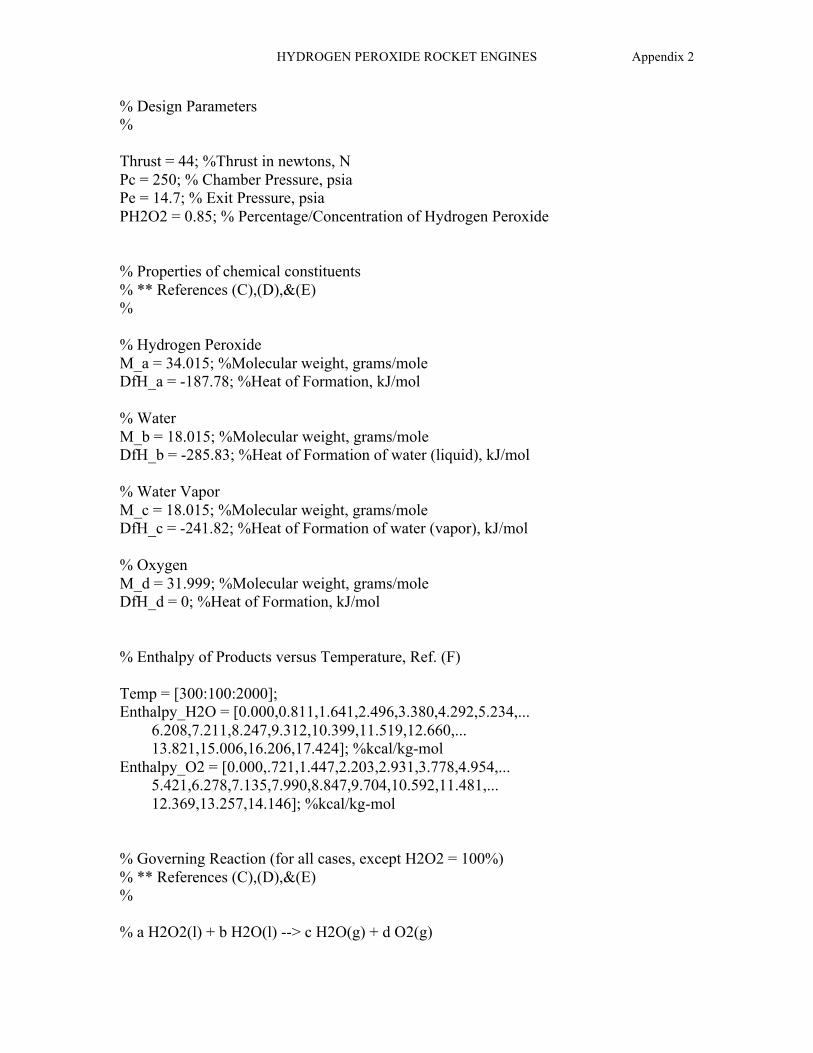
HYDROGEN PEROXIDE ROCKET ENGINES Appendix 2
% Design Parameters % Thrust = 44; %Thrust in newtons, N Pc = 250; % Chamber Pressure, psia Pe = 14.7; % Exit Pressure, psia PH2O2 = 0.85; % Percentage/Concentration of Hydrogen Peroxide % Properties of chemical constituents % ** References (C),(D),&(E) % % Hydrogen Peroxide M_a = 34.015; %Molecular weight, grams/mole DfH_a = -187.78; %Heat of Formation, kJ/mol % Water M_b = 18.015; %Molecular weight, grams/mole DfH_b = -285.83; %Heat of Formation of water (liquid), kJ/mol % Water Vapor M_c = 18.015; %Molecular weight, grams/mole DfH_c = -241.82; %Heat of Formation of water (vapor), kJ/mol % Oxygen M_d = 31.999; %Molecular weight, grams/mole DfH_d = 0; %Heat of Formation, kJ/mol % Enthalpy of Products versus Temperature, Ref. (F) Temp = [300:100:2000]; Enthalpy_H2O = [0.000,0.811,1.641,2.496,3.380,4.292,5.234,... 6.208,7.211,8.247,9.312,10.399,11.519,12.660,... 13.821,15.006,16.206,17.424]; %kcal/kg-mol Enthalpy_O2 = [0.000,.721,1.447,2.203,2.931,3.778,4.954,... 5.421,6.278,7.135,7.990,8.847,9.704,10.592,11.481,... 12.369,13.257,14.146]; %kcal/kg-mol % Governing Reaction (for all cases, except H2O2 = 100%) % ** References (C),(D),&(E) % % a H2O2(l) + b H2O(l) --> c H2O(g) + d O2(g)

HYDROGEN PEROXIDE ROCKET ENGINES Appendix 2
b = 1; % number of moles of H2O(l) rho_a = 1442.5*(1000)/(100^3); % Density of Hydrogen Peroxide rho_b = 1; % Density of Water, gram/cc Mass_H2O = b*M_b; Mass_H2O2 = (PH2O2/(1-PH2O2))*Mass_H2O; ofratio = (Mass_H2O2)/(Mass_H2O); a = Mass_H2O2/M_a; % number of moles of H2O2(l) c = a + b; % number of moles of H2O(g) d = (a*2+b-c)/2; % number of moles of O2 % Determination of Heat of Reaction using simple principles % % (1) Calculation of the Heat of Reaction at STP % ** References (C)&(D) % DrHo = ((c*DfH_c + d*DfH_d) - (a*DfH_a + b*DfH_b))/a; %kJ/mol % (2) Heat available for the reaction % ** Reference (B) % Q_avail = - DrHo; %kJ/mol % (3) Determine the chamber temperature, based upon the Heat % available to raise the products from standard temperature % ** Reference (B) % [z,N] = size(Temp); for i = 1:N Q(i) = (c/a)*Enthalpy_H2O(i) + (d/a)*Enthalpy_O2(i); % Enthalpy in units of kcal/kg-mol Q(i) = Q(i) * 4.184; %kJ/mol if Q(i) < Q_avail LowLim = Q(i); z = i;

HYDROGEN PEROXIDE ROCKET ENGINES Appendix 2
end end UpperLim = Q(z+1); T_low = Temp(z); T_high = Temp(z+1); Tc = ((Q_avail - LowLim)/(UpperLim - LowLim)) * ... (T_high - T_low) + T_low; %Kelvin % (4) Calculate the average molecular weight of the Products % ** References (A)&(B) % Sum_nM = c*M_c + d*M_d; Sum_n = c + d; M = Sum_nM/Sum_n; % (5) Calculate the average specific heat of the Products, % Cp = dH/dT % ** References (A),(B),&(C) frac = (Tc - T_low)/(T_high - T_low); DH_H2O = (frac*(Enthalpy_H2O(z+1) - Enthalpy_H2O(z)) + ... Enthalpy_H2O(z)) * 4184; %J/mol DH_O2 = (frac*(Enthalpy_O2(z+1) - Enthalpy_O2(z)) + ... Enthalpy_O2(z)) * 4184; %J/mol Cp_H2O = DH_H2O/(Tc - 298); Cp_O2 = DH_O2/(Tc - 298); Cp = (c*Cp_H2O + d*Cp_O2)/Sum_n; %J/K-mol % (6) Calculate the specific heat ratio % References (C),(D),&(E) % R = 8.31451; % Universal gas constant, J/K-mol gamma = Cp/(Cp-R); % (*) Summarize the values of steps #1 through #6

HYDROGEN PEROXIDE ROCKET ENGINES Appendix 2
% Tc M; Cp; gamma; P1 = Pc; P2 = Pe; molfracH2O = c/(c+d); molfracO2 = d/(c+d); R = 8314.51/M; % gas constant, J/kg-K % Steps (7) thru (10) are based upon the quasi-1D flow % model with the following additional assumptions: isentropic % nozzle expansion, perfect gas law, adiabatic chamber and % nozzle walls, frozen flow, and no appreciable friction or % boundary layer affects % ** Reference (A) % % (7) Calculate the exhaust velocity % V2 = sqrt( (2*gamma/(gamma-1)) * R * Tc * (1-(P2/P1)^... ((gamma-1)/gamma))); % exit velocity, m/sec % (8) Calculate the thrust coefficient % Cf = sqrt( (2*gamma/(gamma-1)) * gamma * ((2/(gamma+1))^... ((gamma+1)/(gamma-1)))*(1-(P2/P1)^((gamma-1)/gamma))) % (9) Calculate the characteristic velocity % cstar = sqrt(gamma*R*Tc)/(gamma*sqrt((2/(gamma+1))^... ((gamma+1)/(gamma-1)))) %m/sec % (10) Calculate the Isp % Isp = V2/g %sec

HYDROGEN PEROXIDE ROCKET ENGINES Appendix 2
% (11) Determination of thruster P,V,T parameters, using % thermodynamic data % ** Reference (A) & (B) % m_dot = Thrust/V2 % mass flow rate, kg/sec Pc = Pc*6894.757; % Pressure in Pascal, Pa Pt = Pc*(2/(gamma+1))^(gamma/(gamma-1)); % Throat pressure, Pa Tt = 2*Tc/(gamma+1); % Throat temperature, degrees Kelvin T2 = Tc*(P2/P1)^((gamma-1)/gamma); % Exit temperature, deg Kelvin Vt = sqrt((2/(gamma+1))*gamma*R*Tc); % Throat velocity, m/sec % Method of Volumes, per Ref. (A) Volm1 = R*Tc/Pc; % Specific volume of entrance to nozzle, m^3/kg Volmt = Volm1*((gamma+1)/2)^(1/(gamma-1)); % throat, m^3/kg Volme = Volm1*(P1/P2)^(1/gamma); % exit, m^3/kg % (12) Calculate Nozzle expansion ratio and nozzle length % ** Reference (A) % At = (m_dot*Volmt/Vt)*(100/1)^2 % Throat Area, cm^2 Ae = (m_dot*Volme/V2)*(100/1)^2 % Exit Area, cm^2 Dt = sqrt(4*At/pi) % Throat Diameter, cm De = sqrt(4*Ae/pi); % Exit Diameter, cm exp_ratio = Ae/At % expansion ratio % Per Reference (A), p. 78, half-angle is optimal between % 12 and 18 degrees, but may be lower. Mass increases with % nozzle length. If mass is not an issue, then smaller half- % angles may be used. % alpha = 12; % half-angle, degrees alpha_rad = pi*alpha/180; %radians L_cone = ((De/2)-(Dt/2))/tan(alpha_rad); % Steps (13) includes Calculations based upon empirical data %

HYDROGEN PEROXIDE ROCKET ENGINES Appendix 2
% (13) Determine chamber diameter, assuming silver mesh catalyst % ** Reference (G) % Throughput = m_dot * 2.2046 * 60; %lb/min Loading_Factor = 10; Pack_Area = Throughput/Loading_Factor %Catalyst Pack Area, in^2 Catpack_Dia = 2*2.54*sqrt(Pack_Area/pi); %Catalyst Diameter, cm % (14) Determine the Nozzle Correction Factor % ** Reference (A)&(B) % lambda = (1 + cos(alpha_rad))/2; % (15) Modelling of Losses and Predicted Performance % References (A)&(B) % zeta_v = 0.96; % Estimated velocity correction factor Thrust_Efficiency = 0.96; % Estimated thrust correction factor zeta_d = Thrust_Efficiency/zeta_v; % Estimated discharge correction factor Predicted_Thrust = lambda*Thrust_Efficiency*Thrust %Newtons Adjusted_mdot = zeta_d*m_dot; % mass flow rate, kg/sec Predicted_Isp = Predicted_Thrust/(Adjusted_mdot*g) %seconds

HYDROGEN PEROXIDE ROCKET ENGINES Appendix 3
APPENDIX 3

HYDROGEN PEROXIDE ROCKET ENGINES Appendix 3
*********************************************************************** NASA-GLENN CHEMICAL EQUILIBRIUM PROGRAM CEA, OCTOBER 17, 2000 BY BONNIE MCBRIDE AND SANFORD GORDON REFS: NASA RP-1311, PART I, 1994 AND NASA RP-1311, PART II, 1996 *********************************************************************** # Run 11: (Refer to Figure 5 of report) # (a) Rocket problem with infinite-area combustor (rocket iac by default). # (b) The fuel is H2O(L) at 298.17 K; the oxidant is H2O2(L) at 298.17 K. # Both are in thermo.lib so that the enthalpies and "exploded" formulas # do not need to be given. # (c) The oxidant-to-fuel ratio is 49.0(o/f=49.000). # (d) The chamber pressure is 250.0 psia (p,psi=250.0). # (e) Calculations are with equilibrium chemistry only (equilibrium). # (f) For exit points there is one pressure ratios (pi/p=100), problem rocket equilibrium froz o/f=49.000 case=11 p,psi=250.0 pi/p=100.00 reactants fuel = H2O(L) wt% 100. t(k) 298.17 oxid = H2O2(L) wt% 100. t(k) 298.17 output siunits end THEORETICAL ROCKET PERFORMANCE ASSUMING EQUILIBRIUM COMPOSITION DURING EXPANSION FROM INFINITE AREA COMBUSTOR CHAMBER THROAT EXIT Pinf/P 1.0000 1.8099 100.00 P, BAR 17.237 9.5237 0.17237 T, K 1225.45 1085.76 431.15 RHO, KG/CU M 3.8164 0 2.3800 0 1.0847-1 M, (1/n) 22.560 22.560 22.560 Cp, KJ/(KG)(K) 1.8373 1.7767 1.4716 GAMMAs 1.2510 1.2617 1.3341 PERFORMANCE PARAMETERS Ae/At 1.0000 9.6104 CSTAR, M/SEC 1019.3 1019.3 CF 0.6971 1.5916 Isp, M/SEC 710.6 1622.2 MOLE FRACTIONS H2O 0.67501 0.67501 0.67502 *OH 0.00001 0.00000 0.00000 *O2 0.32498 0.32498 0.32498 * THERMODYNAMIC PROPERTIES FITTED TO 20000.K PRODUCTS WHICH WERE CONSIDERED BUT WHOSE MOLE FRACTIONS WERE LESS THAN 5.000000E-06 FOR ALL ASSIGNED CONDITIONS *H HO2 *H2 H2O2 *O O3 H2O(cr) H2O(L)

HYDROGEN PEROXIDE ROCKET ENGINES Appendix 4
APPENDIX 4

HYDROGEN PEROXIDE ROCKET ENGINES Appendix 4
Additional Finding From the Literature Search
History of Hydrogen Peroxide
Hydrogen peroxide has a long and colorful history, contrary to its clear exhaust
plume. Hydrogen peroxide was used on the X-15 experimental plane and the infamous
V2 rocket of World War II (Stokes, 1998). However, its use faded with the generation of
more powerful, yet more toxic, propellants (Keith, 1998). Revitalization of hydrogen
peroxide as a rocket propellant was primarily because the dissociation products are water
and oxygen. Non-toxic exhaust is optimal for such applications as on-board naval
missiles (Minthorn, 1999). Other properties that make hydrogen peroxide desirable
include a high specific weight, potential for low cost, and relatively lower toxicity in the
liquid state compared to other propellants.
Handling
Hydrogen peroxide is considered a “green” propellant. However, being a green
propellant does not preclude dangers in handling. Hydrogen peroxide reacts with organic
material (wood, clothing, etc.) and may induce combustion at high concentrations. In
addition, the PPM concentration of hydrogen peroxide vapor in the atmosphere is strictly
limited for human exposure. Storage requirements are available from the manufacturer
(e.g., FMC, etc.), Fiegenbaum et. al. (1998), Whitehead (1998), Pauls and McMahon
(1999), and other sources. The Material Data Safety Sheets (MSDS) for the chemical
should always be read prior to handling.

HYDROGEN PEROXIDE ROCKET ENGINES Appendix 4
Performance
Hydrogen peroxide may be used effectively as a rocket propellant above 70%
concentration (Whitehead, 1998). A more common rocket propellant grade, high test
hydrogen peroxide (HTP), extends above 85% concentration (Bruce et. al., 2001; Frolov,
1998). The benefit of higher concentration is observed within the performance of the
rocket engine as detailed within Computer Analysis section below. However, as the
concentration increases, the dangers of storage and handling increase as well as the
difficulty of manufacturing (Whitehead, 1998).