Embed Size (px)
Citation preview

Page 1 of 42
Technical Manual
Thermo Siphon System
Solar Energy
This manual is for exclusive use of Bosch installers and technicians of the
authorized service partners.

Page 2 of 42
1) Introduction
Solar thermal systems collect heat from the sun for heating water, for different purposes,
as for central heating, swimming pool heating, or domestic hot water consumption.
The aim of this manual is to give guidelines and best practices recommendations on
domestic hot water use, to Bosch Service Partners and Installers, on Solar Thermo
Siphon Systems for – DHW – Domestic Hot Water production for sanitary purposes.
The manual gives also an overview of the main changes on the actual TSS System from
Bosch, in order to comply with some of the main request given during 2nd generation of
product.
1.1) General Variants of Thermo Siphon Systems
Pict.1 – Direct system representation (source Caleffi)
Pict.2 – Indirect system representation (source Caleffi)

Page 3 of 42
1.2) Thermo siphon working principle
One of the most common system designs is the thermo siphon system. It is perhaps the
most widely used system design in the world. It is based on the natural convection to
collect the heat from the sun and store it in an insulated tank for later end user need. The
sun rays are absorbed by the collector absorber, which heats the fluid inside the collector
tubes. When the fluid is heated inside the collector tubes, its density decreases and,
naturally, the fluid goes up and enters inside the tank, which is on the top of the collector.
After transferring its energy, the cooler fluid from the tank drops down into the bottom of
the collector and the cycle continues, as long as the sun is able to heat the fluid in the
collector.
Insulation in the back and sides of the collector and the glazing in the front of the collector
allow it to collect heat during the day, at much higher temperatures than the surrounding
ambient air. The insulated tank reduces heat losses, so the heated water can be stored
for long periods of time until it is consumed. The roof structure must be able to support
the whole system weight or, an alternative installation area must be considered.
In order to ensure a natural convection effect to work in a thermo siphon system, the
storage tank must always be installed at a level above the top header of the collector.
Pict.3 – Example of solar thermo siphon system

Page 4 of 42
2) Installers Brief
The largest market for solar thermal installers has traditionally been in retrofit situations.
In retrofit settings, the installer takes whatever conditions they find and makes things
work.
During the construction of new residences, the emphasis should be on systems
integration, optimal design, and interaction with other trades. Nevertheless, best practices
and good conduct will help the installers in new contracts and installations’, leaving a
good image of the Brand and it’s after sales organization.
• Use specialized knowledge to educate constructors. New construction provides an
opportunity to optimize the equipment and installation process;
• Work with site supervisors, roofers, plumbers, and other specialists, to determine
the best installation sequence and schedule what materials should be provided, in
order to optimize working sequence and to avoid unnecessary work, roof
penetrations, etc;
• Confirm solar exposure before mounting any equipment on the roof, to avoid
shadows from vents, trees and/or buildings;
• Provide quality assurance inspections and maintenance contracts with end users;
• Select packages that preserve floor space and maintain a tidy appearance;
• Use quality assurance techniques to avoid problems;
• Work with the constructor to develop inspection protocols;
• Correct any installation problems immediately, in order to ensure a good image
and sense of respect and professionalism from the brand, to the end user;
• Protect pipe circuit from other trades that may also need access to the same
spaces or that may need to create circuits of their own;
• Label and fix pipe circuits, so that they are not pushed up and out of the way,
creating water traps and freeze hazards.
It may be necessary to ensure having teams to do pre-installations, collector installations,
and interior component installations. Different teams may do these tasks simultaneously,

Page 5 of 42
or one team may have different jobs at different times. Be clear with the site supervisor
about demands for teams intervention time.
Work with site supervisors, roofers, plumbers, and others to determine the best time to
schedule and what materials to provide. Pay attention to other trades that will be working
in the same space.
For the operations of pre-installation check, installation or maintenance, take care always
of the necessary devices and tools for safety assurance. Workers must be protected from
difficulties or obstacles in the field, in order to avoid accidents.
A safety check-list is recommended in order to ensure, before the beginning of work
activities, that all the necessary equipment of protection and installation are available.
2.1) Identification of risks during works on the roof by service partner or installer
– Installation of heavy objects;
– Execution of works on the roof or higher positions;
– Protection of fragile materials;
– Presence of plumbing pipes (gas or others fluids);
– Proximity to high voltage wires or other electrical cables;
– Atmospheric conditions (wind speed, rain, etc);
Pict.4 – Identification of risk areas in installation and servicing of TSS systems

Page 6 of 42
2.2) Identification of the equipment and safety material needed
a) Equipments for collective protection
- Railings
- The scaffolds (fixed or not)
- Fixed stairs
- Motorized elevation platform
- Motorized platform to elevate material without damages;
Pict.5 – Example of collective protections (scaffolds and stairs)
Pict.6 – Example of elevation platforms for material / persons

Page 7 of 42
b) Equipment for individual protection
- Helmet
- Safety Shoes
- Protective gloves
- Harnesses
- Safety glasses
- Hearing Protectors
Pict.7 – Example of individual protections
c) Complementary equipments of protection
- Stop losses
- Locking Solo
- Pole attachment
- Temporary Lifeline
- Anchor Point Roof
- Belt Tools
Pict.8 – Example of complementary safety tools

Page 8 of 42
Attention:
The installer is responsible to install the equipments properly, the do the connection and
interface with existent backup heating appliances and / or accessories and the start up of
the system, ensuring correct and proper working.
The technician is responsible for check Installation system, repair and inform end user of
an eventual correction need by the Installer, ensuring safety and a proper operation of the
system supplied by Bosch.
At the end of the installation activities, the system documentation should be given and
explained to the end user and a maintenance contract should be done in order to prevent
any system problems.
3) General Concepts
On a clear day, solar radiation is most intense at solar noon (e.g., that time of day when
the sun reaches its highest position in the sky and directly above a polar north/south line).
Before striking the earth’s atmosphere, solar radiation travels in straight paths. This is
called the “direct” solar radiation. On a clear day, the majority of solar radiation striking
the earth’s surface is direct radiation and, because of travelling in straight lines, direct
radiation is easy to reflect.
If there was no atmosphere, nearly all the solar radiation that would reach the earth
surface would be direct radiation, however, the gas and vapour molecules in the
atmosphere create a very different scenario. They reflect a significant portion of the
incoming direct radiation in every direction. The result is called “diffuse” solar radiation. Its
presence is the reason why we see the sky and objects around us in a very different way
as they could be seen in space, without atmosphere.
The majority of solar radiation reaching the earth surface on cloudy days is diffuse
radiation and this one cannot be easily focused.

Page 9 of 42
Pict.9 – Overview of solar energy incidence in Europe
3.1) Solar Orientation
The orientation of the solar collectors should be always facing sun position and trajectory
according to the solar diagram of its localization.
We have so:
- North hemisphere – orientation facing South
- South hemisphere – orientation facing North
Pict.10 – Example of orientation and solar trajectory (source Caleffi)

Page 10 of 42
However, and in order to adapt to a real situation or to avoid sun obstacles, short
deviations to east or west are acceptable without a big decreasing of system efficiency,
with a maximum recommended deviation of ± 20º.
Deviation until - 20º East Deviation until + 20º West
Pict.11 – Collector orientation to South in North Hemisphere
Deviation until - 20º East Deviation until + 20º West
Pict.12 – Collector orientation to North in South Hemisphere
3.2) Collector Inclination
The solar collector angle is usually the correspondent one with the latitude of the
installation place, nevertheless, in the thermo siphon system in flat roof, the angle is fixed
and in the on roof installation, generally is used the roof tilting to support system.
As a general rule, the following consideration can be taken in consideration:

Page 11 of 42
Thermo siphon system with flat roof support system:
- Fixed angle of the support structure
Thermo siphon system on roof:
1. Inclination = Latitude of location – 15º
Note: This situation is better to improve Domestic Hot Water (DHW) production in
summer;
2. Inclination = Place latitude – 5º
Note: This situation is better to have in a installation working during whole year
(ideal for TSS);
3. Inclination = Latitude of location + 15º
Note: This situation is better to improve DHW production in winter
Pict.13 – Example of different collector inclinations
Pict.14 – Collector inclination adaptation
3 2 1

Page 12 of 42
3.3) Shadows
The existence of buildings, trees or other obstacles in front of a solar system can be a
problem and reduce the system efficiency, decreasing the number of sun exposition
hours to the available solar energy.
These situations must be verified before installation with the correspondent solar diagram
of the location, and communicated to the end user, in order to know the consequences of
a solar fraction reduction.
Solution can be the increase of the solar area exposition or the adaptation of an adequate
backup solution.
Pict.15 – Example of obstacle to a solar system for latitude N 40º

Page 13 of 42
Pict.16 – Example of solar diagram for a location at latitude of 40º N
Pict.17 – Example of a solar diagram for 40 N latitude and obstacle influence indication
Also the obstacles in the installation place should be considered, for example in case of
walls or other systems that might provoke shadows on the collector.

Page 14 of 42
Pict.18 – Example of formula to calculate distance between rows of solar systems
Pict.19 – Example of simplified formula to calculate distance until the nearest wall
4) Solar System
Solar water heaters differ from conventional water heaters in two fundamental
characteristics. The first and most obvious is that, most of the primary energy used to
heat the water is provided free by the environment in which the heater is placed. The
second difference is that the input to this primary source of energy varies from season to
season. Often, the annual variation ranges from low levels of solar energy at times of
higher need to excessive level for times of less energy need.
Not only does the primary energy source vary with the seasons, but it often varies widely
from day to day. If this free energy component is to be maximised under these
circumstances, the storage capacity and insulation properties of a solar water heater
need to be greater than those of a conventional hot water system. This way, it is possible

Page 15 of 42
to accumulate some residual energy from a previous good day to one for which the solar
input may be not sufficient.
Solar hot water systems also require auxiliary energy supplies. These are usually
provided by a heating element as an electric resistance immerged in the water, or using
an instantaneous gas water heater installed in series with the solar system.
To ensure that an auxiliary element does not waste energy on heating water more than
required, the element is located in the centre of the vessel. In this way, the element heats
only the upper part of the stored water, however and as we are talking about big storage
tanks, it’s recommended the use of a backup appliances of instantaneous gas water
heaters with adequate accessories, in order to heat only when hot water consumption is
needed, avoiding extra heating consumption of electricity, when there is no tapping and
with a possible re-heating by the free energy of the sun.
Pict.20 – Cut view of Bosch solar tank
4.1 – Storage Tank – enamelled vitreous
The internal surface of the vessel is treated with a coat of enamelled vitreous. This
treatment is applied to protect the steel surface of the vessel against corrosion attack
and, is considered to be one of the the best corrosion protection methods for steel
vessels, from the point of view of hygienic purposes for domestic hot water applications
and durability.
The reasons are the following:
- resistance to corrosion.
- resistance to permanent scale deposition

Page 16 of 42
- resistance to high temperatures.
The enamel comprises a mixture of silica and clays that, when fused, has a coefficient of
expansion comparable to the one of the steel. The vessel and clay mixture are heated till
860°C and the resultant enamel melts and fuses covering the steel surface. When
cooling, the steel vessel contracts at a slightly greater rate than the enamel and it’s
therefore, under a slight compressive stress at low temperature. (Glass is extremely
strong in compressive strength).
In normal operation, the vessel can be heated up to 99°C and will therefore tend to
relieve only some of the pre-stressed compression.
In practice, large and sudden temperature variations between the enamel lining and the
vessel wall do not occur.
Pict.21 – Internal view of the vessel tank
Water has considerable thermal inertia, (time required for a temperature change with
application or withdrawal of heat). The intimate bond of the enamel with the vessel
prevents temperature gradients between the glass lining and the steel body.
The enamelling process is essential for the long life under the high temperature
conditions that might occur on solar hot water systems, even with large collector areas
and higher performance collectors.

Page 17 of 42
4.2) Magnesium anode and corrosion protection
The storage tank is fitted with a replaceable magnesium anode. The use of an anode in
corrosion protection is known as a cathode protection system.
The anode is protects all non covered enamel lining areas.
Pict.22 – Anode and its accessibility
The time life of the anode depends on different factors such as:
- type of anode (material);
- type of water (conductivity and pH);
- temperature of the water.
Essentially the life of the anode is determined by its natural solubility in the water where it
is immerged. For this reason, the life of the anode is quite variable.
Due to the time life variation, we strongly recommend a yearly inspection and than, the
replacement according to the results from the firs inspection: Note: the replacement of the
anode is much less expensive than replacing the vessel.

Page 18 of 42
Attention: In areas with bad water quality, the anode may need to be changed very
frequently.
Pict.23 – example of different corrosion level of the anodes
Corrosion is a chemical reaction that takes place on the surface of a metal. The worse
common reaction in the rusting of iron is the reaction with water and dissolved oxygen.
The severity of the corrosion attack from fresh water on metal varies widely, depending
on the dissolved salts and gases in the water. The principal corrosive agents are
chlorides, sulphur compounds, iron compounds and calcium salts.
The enamelling protection has advantages when compared with stainless steel, because
is not totally stainless and is susceptible to various insidious forms of corrosion such as
stress and crevice corrosion. This is particularly prevalent when, in the presence of high
temperatures, the metal is subject to high operational stress and high chlorides.
Corrosion occurs by a number of mechanisms, however in the case of water heater
cylinders they are mainly:
- Pit and Crevice Corrosion
- Stress Corrosion
- Corrosion Fatigue.
- Galvanic Corrosion
Water hardness is defined by the concentration of calcium ions (Ca++) and magnesium
(Mg ++) responsible by the deposition of calcaire in the interior of pipes and tanks,
provoking problems as decrease of water flow and / or temperature exchange.

Page 19 of 42
This hardness is generally indicated in ºF (French degrees).
Water Hardness
= 4 mg/l de Ca++
1°F = 2.4 mg/l de Mg++
= 10 mg/l de CaCO3
The water is :
• Soft when hardness is 0 à 18°F, • Mid-hard when hardness is 18 à 30°F, • Hard when hardness is + de 30°F.
As reference, the following values can be used as indicative for good water for domestic
purposes:
Water Quality
Type of Measurement Limits
pH 6,5 à 9
Conductivity 400 µS/cm à 20°C
Chlorides 0,1 mg/l
Temperature 15°C
Water Hardness 4 à 8°F
4.3) Water stratification
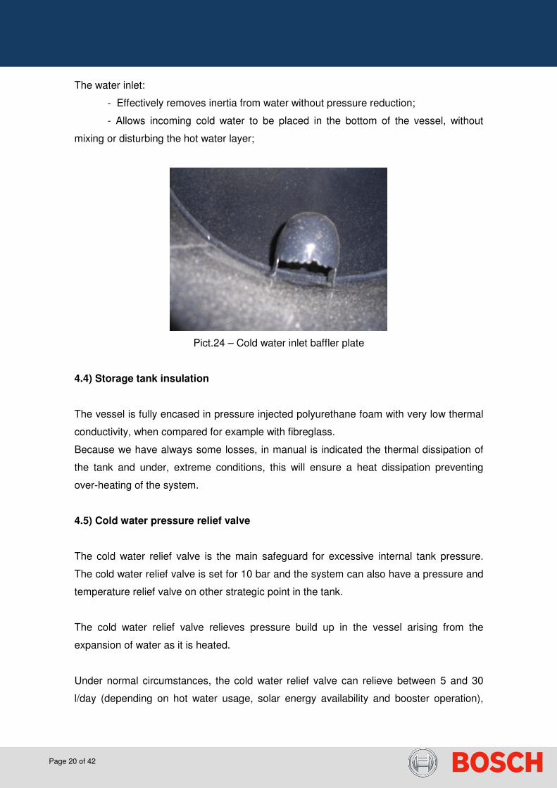
The baffler plate in the inlet of water prevents the mixture of the cold water entering in the
vessel with the hot water already inside the tank. This promotes thermal stratification of
the vessel contents.
The device achieves this through a combination of its shape and inverted outlet slot. The
velocity of the incoming water is dropped and the inertia, dissipated by the device. The
cold inlet water drops from the baffler plate through the inverted outlet slot and lies on the
bottom of the vessel. The temperature of the hot water already in the tank is therefore not
diluted which results on an enhanced hot water delivery capacity of the system.
Page 20 of 42
The water inlet:
- Effectively removes inertia from water without pressure reduction;
- Allows incoming cold water to be placed in the bottom of the vessel, without
mixing or disturbing the hot water layer;
Pict.24 – Cold water inlet baffler plate
4.4) Storage tank insulation
The vessel is fully encased in pressure injected polyurethane foam with very low thermal
conductivity, when compared for example with fibreglass.
Because we have always some losses, in manual is indicated the thermal dissipation of
the tank and under, extreme conditions, this will ensure a heat dissipation preventing
over-heating of the system.
4.5) Cold water pressure relief valve
The cold water relief valve is the main safeguard for excessive internal tank pressure.
The cold water relief valve is set for 10 bar and the system can also have a pressure and
temperature relief valve on other strategic point in the tank.
The cold water relief valve relieves pressure build up in the vessel arising from the
expansion of water as it is heated.
Under normal circumstances, the cold water relief valve can relieve between 5 and 30
l/day (depending on hot water usage, solar energy availability and booster operation),

Page 21 of 42
however, this can also be avoided in case of the installation of an optional accessory as a
membrane expansion vessel.
The actual valve keeps same functions (non-return, pressure relief and cut) but was
modified in dimensions and is installed in Horizontal position leaving more space,
especially for installations on roof.
Pict.25 – Cold water pressure relief valve
4.6) Storage tank heat exchanger
The solar energy collected by the solar collectors is transferred to the water in the vessel
over the steel wall of the vessel. The large heat exchange wall area, combined with a low
heat exchange rate, assures that the glazed inside surfaces are not excessively heated.
This minimises the build-up of scaling inside of the vessel.
Solar fluid inside the outlet jacket Sanitary water inside the tank
Pict.26 – Cut section of a heat exchanger (double jacket type)

Page 22 of 42
4.7) Solar Circuit
The solar fluid available is manufactured to comply with strict health and water authority
regulations under food-grade conditions.
The solution is supplied for direct use and will protect the system against freeze damage
till -14°C. Polypropylene glycol is safe in case of possible ingestion or absorption through
the skin.
The application of the solar fluid will prevent the collector from damages caused by
freeze.
Pict.27 – Glycol used by Bosch is Tyfocor L type
Pict.28 – Solar liquid (Glycol) circuit between collector and heat exchanger

Page 23 of 42
In order to prevent abnormal temperature and pressure reactions in the closed loop, a
pressure relief valve is installed in the top of the tank as indicated in picture 28. It will be
activated around 2,5 bar, however the solar collector is tested and proved until 6 bar.
Pict.29 – Solar circuit pressure relief valve
In this closed loop, the solar fluid is in normal circulation due to the density difference,
however, after some time, the fluid can degrade, depending on some conditions as
excessively sun exposition or long periods of stagnation temperatures.
In order to prevent degradation of solar fluid, the technician or installer should use for
maintenance purposes, the following tools:
Bosch WTI part – PH control strips
Bosch WTP part – density level control
Pict.30 – WTI and WTP tools for solar fluid controls
Following image, gives the indication of the correspondent hydraulic connections and
accessories.

Page 24 of 42
Pict.31 – Solar thermo siphon system connections
1 – Solar storage tank (double jacket type);
2 – Cold water inlet (cold water pressure relief valve connection);
3 – Solar circuit return from heat exchanger to collector;
4 – Cap;
5 – Return pipe;
6 – Way pipe;
7 – Hot water outlet (thermostatic valve installation);
8 – Solar circuit way connection to the heat exchanger;
9 & 10 – Solar circuit pressure relief valve connection and filling connection.
5) Integration on existent installation place
In case of integration of the solar system with existing appliances as backup, the working
conditions must be known, in order to prevent and install the adequate accessories to
avoid water scalding or damages on the appliance.

Page 25 of 42
Pict. 32 – Solar Installation examples with integration on roof or flat with existent
appliances
For these situations, installer should be informed of the type of appliance, in order to
advice the correct complementary backup solution to install, or the accessory to adapt to
the existent solution.
Nevertheless, backup system must be always considered, as the solar radiation intensity
is always dependent on weather conditions.
Examples of backup solutions:
- Appliance in serial connection with the solar system, in order to start
working when the temperature from solar is not enough. Usually
instantaneous gas water with enough power to assure that the
instantaneous heating is adequate, however and for safety reasons an
adaption accessory might be needed.
- Electric heating element controlled by a thermostat connected with the
water inside of the tank This solution is not so efficient as the previous
one and takes more time to ensure the desired temperature.
The protection of the appliances and / or users from high hot water supply, mainly during
high sun radiation period can be done by different accessories:
Page 26 of 42
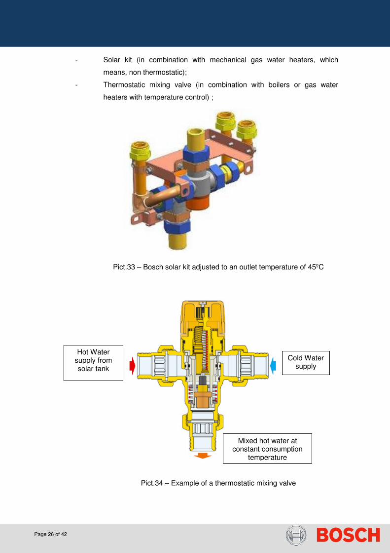
- Solar kit (in combination with mechanical gas water heaters, which
means, non thermostatic);
- Thermostatic mixing valve (in combination with boilers or gas water
heaters with temperature control) ;
Pict.33 – Bosch solar kit adjusted to an outlet temperature of 45ºC
Pict.34 – Example of a thermostatic mixing valve
Cold Water supply
Hot Water supply from solar tank
Mixed hot water at constant consumption
temperature

Page 27 of 42
Pict.35 – Example of an adjustable selector of mixing valve and
correspondence between position and temperature of outlet hot water
5.1) Backup with gas water heater
The solar kit will prevent the entry of high temperature to the appliance, and deviate the
hot water (> 45ºC) to a second valve (mixing) in order to ensure the desired outlet
temperature of 45ºC. In case of insufficient water temperature from solar, the first valve
deviates the hot water from solar to the gas water heater in order to heat it up and then,
in the second valve (mixing), it ensures the outlet water temperature of 45ºC
Attention: These are only general indications, but before any further use, the
correspondent manual of solar kit must be read.
Advantages:
� avoid damages on the appliance due to high temperatures;
� avoid scalding of end user;
� avoids the use of a thermostatic gas water heater;
� the backup appliance will only operate when the hot water temperature from solar
is less than 45ºC;

Page 28 of 42
� less water heater maintenance costs, due to less working periods.
Pict.36 – Example of an installation scheme of thermo siphon with gas water heater
Pict.37 – Working principle when water from solar is higher than 45º
Page 29 of 42
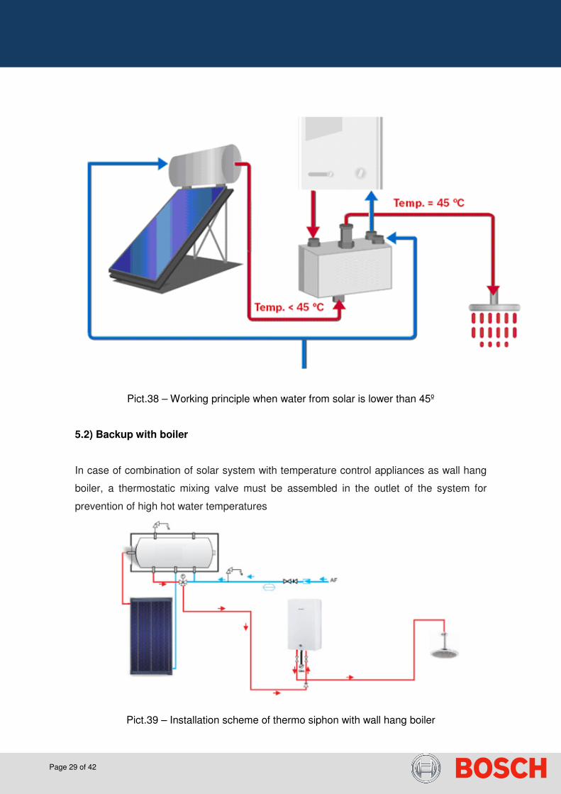
Pict.38 – Working principle when water from solar is lower than 45º
5.2) Backup with boiler
In case of combination of solar system with temperature control appliances as wall hang
boiler, a thermostatic mixing valve must be assembled in the outlet of the system for
prevention of high hot water temperatures
Pict.39 – Installation scheme of thermo siphon with wall hang boiler

Page 30 of 42
5.3) Backup with electric heating element
In some cases, where instantaneous gas appliances can not be used, the direct heating
through an electric resistance is possible with an available accessory as indicated in
picture 39.
The working principle is similar to the one of a normal electric storage tank that, when the
thermostat control detects a need of heating, the heating element is electrically
connected and starts warming the water inside the tank. At the same time, the
temperature control thermostat is a safety element acting as a temperature limiter.
Pict.40 – Electric resistance and detail of temperature adjustment in thermostat
ATTENTION:
- Read the resistance installation manual 6 720 680 229
- The correspondence between electric power and water volume must be
10 W/l (e.g.: don’t install a resistance of 3000 W in a tank of 200 l, it
should have a maximum of 2000W)
- The cable area must be 2,5 mm2
Pict.41 – Installation scheme of a system with electric resistance and thermostatic valve

Page 31 of 42
6) Solar system maintenance
It is strongly recommended a dedicated and specialized maintenance program in order to
ensure the time life of the system and avoid consequences to the end user. As good
practice, Bosch recommends the Installer to make a visit within 6 or 12 months after the
start up of the system and help the end user on establishing a maintenance program
contract with the official Bosch after sales partner.
Technician and / or Installer should advice the end user about the importance of having
the solar collector glass clean (when system is accessible to end user), and contact him
immediately, in case of detecting any type of leakage in the system.
The table 1 shall be consider as a guideline with the most important points to be checked
and with a safe recommendation of inspection time; however, it will be acceptable by
Bosch the adaptation of this tasks by specialized technicians, after sales or installers
according to their own field experience with similar products.
Component Type of
intervention
Frequency
(months) Comments
Collector Inspection 12
Visual inspection to detect internal condensation and other defects.
In case of condenses, clean air vent holes in the collector and check
sealing joint by all surface and structure.
Collector -
glass Cleaning 12
Ensure Cleaning of the glass and in case of need use water and
soap to clean superficial dirtiness. Make this operation in a time
Schedule where sun is not too Strong (morning or end of the day).
Collector -
absorber Inspection 12
Check for corrosion or deformation in the black chrome copper
surface. In case of damaged absorber, replace collector.
Structure Inspection 24 Check all parts and its fixation and avoid corrosion formation in the
fixing elements. Check if screws are tightened.
12
Check the existence of leakages in the inlet and outlet of domestic
water and in case of need replace gaskets or other sealing material
used. Sanitary
water pipes Inspection
24 In case of existence of insulation, check its good status in all pipe
way.
Solar circuit
pipes Inspection 12
Check the existence of leakages in the tank and collector
connections. Replace pipes in case of damaged pipes, restricted or

Page 32 of 42
blocked and use always new fixation clips.
Test 12
Check by manual activation, the correct working of the pressure
relief valve avoiding the blocking of the safety device due to no
activation. Storage Tank
Inspection 12
Open visit trap and check insulation and presence of calc or
sediments inside of the tank. In case of need, clean internal tank of
sediments deposition with a vacuum cleaner.
Solar Fluid Test 12 Check density and PH of solar liquid with appropriate device (see
table 3)
Magnesium
anode Inspection 12 Check visually the status of the magnesium anode (see table 2)
Table 1 – Suggestion of a maintenance program
6.1) Structure control
The new TSS 3rd generation has include some changes in the aluminum structure in
order to reduce complexity, but keeping the same robustness.
The following key points should be checked during maintenance in order to be sure that
system is correctly attached to roof supports.
Pict.42 – Structure of a thermo siphon and important fixing points (TSS 3rd Generation)

Page 33 of 42
6.2) Magnesium anode control
The criteria for the control of the magnesium anode is checking its visual aspect and
when possible, checking its diameter, weight and dimension. In order to help service, the
following table gives an indication of the minimum values to be considered.
Model Weight
(Initial)
Weight
(minimum)
Diameter
(Initial)
Diameter
(minimum)
Length
(Initial)
Length
(minimum)
TSS 150 422 g 280 g 20 mm 13 mm 600 mm 400 mm
TSS 200 422 g 280 g 20 mm 13 mm 600 mm 400 mm
TSS 300 531 g 354 g 25 mm 16 mm 1120 mm 740 mm
Table 2 – Minimum control values for the magnesium anode
Pict.43 – Corroded anode in a tank
6.3) Solar liquid control
Before filling the solar fluid in the system, ensure that the “Glycol” of direct use, is well
mixed in the supplied recipient and before use, shake the vessel to ensure good mix.
Attention: Solar collectors must be cold before and during filling process for the system.

Page 34 of 42
Pict.44 – Cover the collector to fill with solar fluid, keeping it cold
Pict.45 – PH control with WTI and density control with WTP device
The following table, give to the service man the indication of the recommended values of
the two parameters of the solar fluid.
Inspection Frequency Value Maximum value
(limit) Comments
PH control PH between
7 and 9
Replace if PH < 5
or > 9 (acid or
basic fluid)
Density
control
Every year
Protection
until -14 ºC
Replace if value is
> -5 ºC
Even with
acceptable
values, replace
solar fluid every 4
years (after 60
months)
Table 3 – Solar fluid control

Page 35 of 42
6.4) Pipe Work Inspection
Insulation must be in good conditions to reduce thermal dissipation and efficiency
decreasing, especially in the accessories of connection.
In case of existence of pipes, crossing areas with personal movement, the pipes must
have mechanical protection.
Pict.46 – Missing Items: mechanical protection in cold water pipe and thermal insulation
in hot water pipe
Pict.47 – Correct insulation of connections of solar circuit

Page 36 of 42
Attention:
For guarantee activation, installer should communicate serial number and manufacturing
date visible in the sticker on the protection cover of the resistance and on the side of the
solar collector.
Pict.48 – Type plates and product identification
Annex Modifications included in TSS 3rd generation:
1) Changes on TSS Structure
a. Flat Roof – reduction of number of parts, reducing complexity
b. On Roof – improve of double ended screw support and reduction of
complexity in model TSS300 (independent collector installation and
separation of the structure fixation of the tank)
Example from collector 8370 – Plant identification; 004 – Manufacturing date (FD); 000016 – Counter number;
Example from tank 8370 – Plant identification; 004 – Manufacturing date (FD); 000005 – Counter number;

Page 37 of 42
2) Introduction of new solar collector FCB and FCC on TSS Systems (please check
FPI of SKW Project for details concerning collector)
Pict.49 – Detail of FCB / FCC collector
3) New Pressure relief valve
a. Horizontal Installation
b. Smaller dimensions
Pict.50 – System TSS200 with FCC Collector

Page 38 of 42
In terms of Installation, the following situations are accepted by after sales
1) Complete TSS system with Hooks only (please check)
Pict.51 – System installed with Hooks from image above

Page 39 of 42
2) Complete TSS system with double ended screw only (please check)
Pict.52 – System installed with double ended screws from image above

Page 40 of 42
3) TSS system installed with hooks in the collector area and double ended screw in
the storage tank support.
Pict.52 – System installed with both accessories and overview of change done in TSS 3rd
generation with the separation from collector fixation and tank
Pict.53 – System installed with double ended screw on tank structure and hooks in
collector area

Page 41 of 42
Pict.54 – For TSS300, collector profile support is with one length only as image shows
Pict.55 – Introduction of change in the double ended screw support in order to keep
profile in place
Page 42 of 42
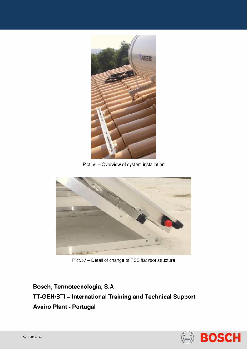
Pict.56 – Overview of system installation
Pict.57 – Detail of change of TSS flat roof structure
Bosch, Termotecnologia, S.A
TT-GEH/STI – International Training and Technical Support
Aveiro Plant - Portugal