Embed Size (px)
Citation preview
2CD
C 2
51 0
04 V
0014
Data sheetData sheet
Thermistor motor protection relaysCM-MSS.12 and CM-MSS.13
The thermistor motor protection relays
CM-MSS.12 and CM-MSS.13 monitor the winding
temperature of motors and protect them from
overheating, overload and insufficient cooling.
The devices are available with two different
terminal versions. You can choose between
the proven screw connection technology
(double-chamber cage connection terminals) and
the completely tool-free Easy Connect Technology
(push-in terminals).
Characteristics – 1 measuring circuit – Automatic reset – Overvoltage protected supply and measuring inputs – Increased interference immunity acc. to EN 62061 with
evaluation criterion "Fail-Safe" – According to the latest version of the product standard
IEC 60947-8 – Screw connection technology or
Easy Connect Technology available – Housing material for highest fire protection classification
UL 94 V-0 – Tool-free mounting on DIN rail as well as demounting – 22.5 mm (0.89 in) width
Order data
Type Rated control supply voltage Output contacts Connection technology Order code
CM-MSS.12P 24 V AC/DC * 1 c/o (SPDT) contact Push-in terminals 1SVR740700R0100
CM-MSS.12S Screw terminals 1SVR730700R0100
CM-MSS.13P 110-130 V AC, 220-240 V AC Push-in terminals 1SVR740700R2100
CM-MSS.13S Screw terminals 1SVR730700R2100
* Supply and measuring circuits not electrically isolated
Approvals
A UL 508, CAN/CSA C22.2 No.14
C GL
R EAC
K CB scheme
E CCC
Marks
a CE
b RCM
2 - Thermistor motor protection relays CM-MSS.12 and CM-MSS.13 | Data sheet
Connection technology
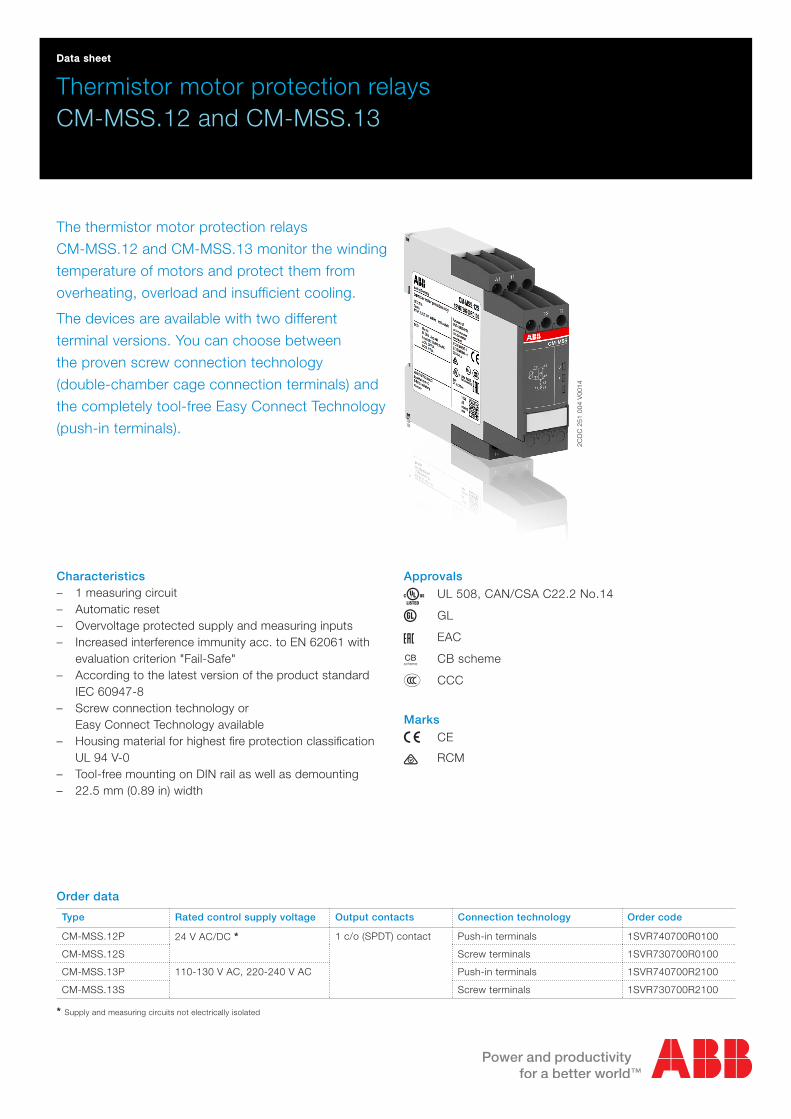
Maintenance free Easy Connect Technology with push-in terminals
Type designation CM-xxS.yyP
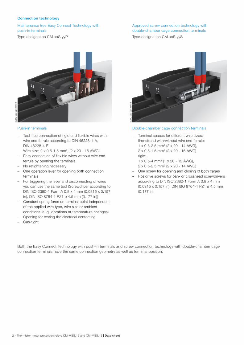
Approved screw connection technology with double-chamber cage connection terminals
Type designation CM-xxS.yyS
Push-in terminals
– Tool-free connection of rigid and flexible wires with wire end ferrule according to DIN 46228-1-A, DIN 46228-4-E Wire size: 2 x 0.5-1.5 mm², (2 x 20 - 16 AWG)
– Easy connection of flexible wires without wire end ferrule by opening the terminals
– No retightening necessary – One operation lever for opening both connection
terminals – For triggering the lever and disconnecting of wires
you can use the same tool (Screwdriver according to DIN ISO 2380-1 Form A 0.8 x 4 mm (0.0315 x 0.157 in), DIN ISO 8764-1 PZ1 ø 4.5 mm (0.177 in))
– Constant spring force on terminal point independent of the applied wire type, wire size or ambient conditions (e. g. vibrations or temperature changes)
– Opening for testing the electrical contacting – Gas-tight
Double-chamber cage connection terminals
– Terminal spaces for different wire sizes: fine-strand with/without wire end ferrule: 1 x 0.5-2.5 mm² (2 x 20 - 14 AWG), 2 x 0.5-1.5 mm² (2 x 20 - 16 AWG) rigid: 1 x 0.5-4 mm² (1 x 20 - 12 AWG), 2 x 0.5-2.5 mm² (2 x 20 - 14 AWG)
– One screw for opening and closing of both cages – Pozidrive screws for pan- or crosshead screwdrivers
according to DIN ISO 2380-1 Form A 0.8 x 4 mm (0.0315 x 0.157 in), DIN ISO 8764-1 PZ1 ø 4.5 mm (0.177 in)
Both the Easy Connect Technology with push-in terminals and screw connection technology with double-chamber cage connection terminals have the same connection geometry as well as terminal position.
2CD
C 2
53 0
25 F
0011
2CD
C 2
53 0
26 F
0011
Data sheet | Thermistor motor protection relays CM-MSS.12 and CM-MSS.13 - 3
Functions
Operating controls
2CD
C 2
51 0
04 V
0014
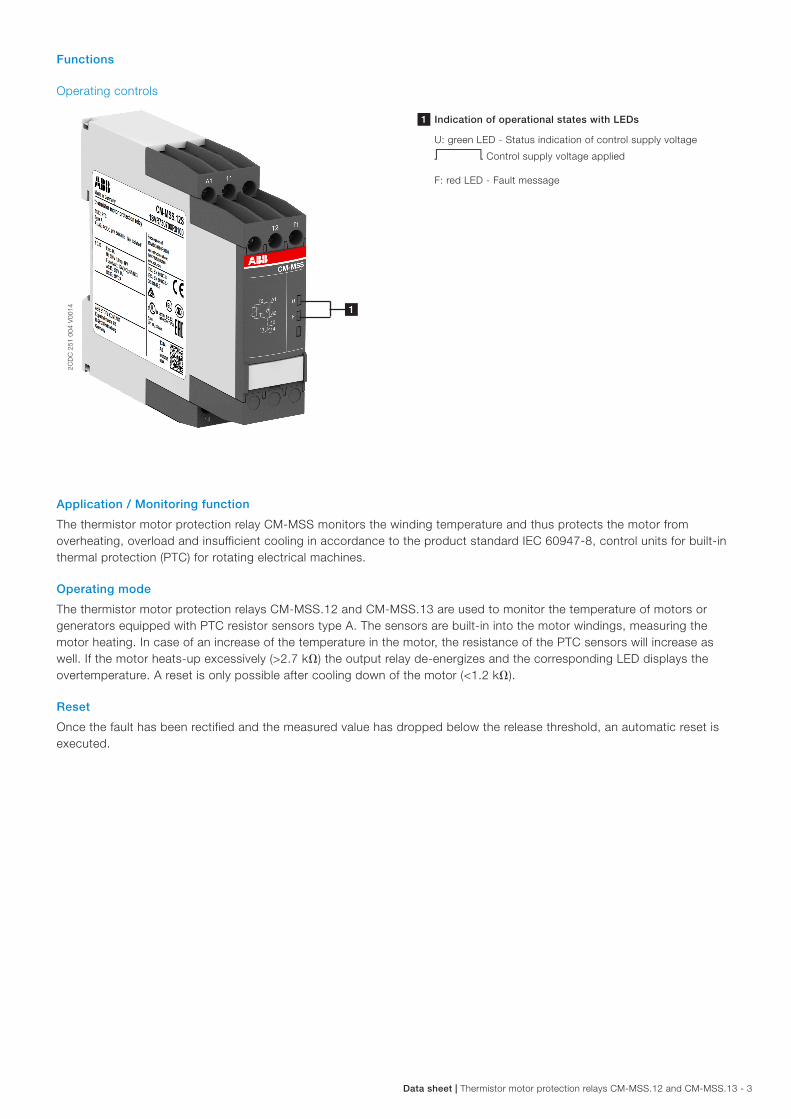
1 Indication of operational states with LEDs
U: green LED - Status indication of control supply voltage
V Control supply voltage applied
F: red LED - Fault message
Application / Monitoring function
The thermistor motor protection relay CM-MSS monitors the winding temperature and thus protects the motor from overheating, overload and insufficient cooling in accordance to the product standard IEC 60947-8, control units for built-in thermal protection (PTC) for rotating electrical machines.
Operating mode
The thermistor motor protection relays CM-MSS.12 and CM-MSS.13 are used to monitor the temperature of motors or generators equipped with PTC resistor sensors type A. The sensors are built-in into the motor windings, measuring the motor heating. In case of an increase of the temperature in the motor, the resistance of the PTC sensors will increase as well. If the motor heats-up excessively (>2.7 kh) the output relay de-energizes and the corresponding LED displays the overtemperature. A reset is only possible after cooling down of the motor (<1.2 kh).
Reset
Once the fault has been rectified and the measured value has dropped below the release threshold, an automatic reset is executed.
1
4 - Thermistor motor protection relays CM-MSS.12 and CM-MSS.13 | Data sheet
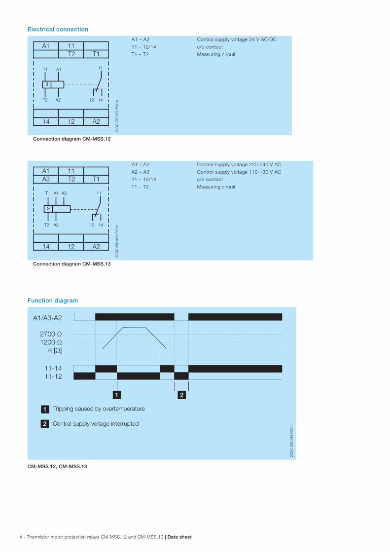
Electrical connection
A1 11T2 T1
14 12 A2
T2
T1 A1
A2 12
11
14
ϑ
2CD
C 2
52 0
22 F
0014
A1 – A2 Control supply voltage 24 V AC/DC
11 – 12/14 c/o contact
T1 – T2 Measuring circuit
Connection diagram CM-MSS.12
A1A3
11T2 T1
14 12 A2
ϑ
T2
T1 A1 A3
A2 12
11
14
2CD
C 2
52 0
20 F
0014
A1 – A2 Control supply voltage 220-240 V AC
A2 – A3 Control supply voltage 110-130 V AC
11 – 12/14 c/o contact
T1 – T2 Measuring circuit
Connection diagram CM-MSS.13
Function diagram
A1/A3-A2
2700 Ω1200 Ω
R [Ω]
1 2
11-1411-12
1 Tripping caused by overtemperature
2 Control supply voltage interrupted
2CD
C 2
52 0
45 F
0214
CM-MSS.12, CM-MSS.13
Data sheet | Thermistor motor protection relays CM-MSS.12 and CM-MSS.13 - 5
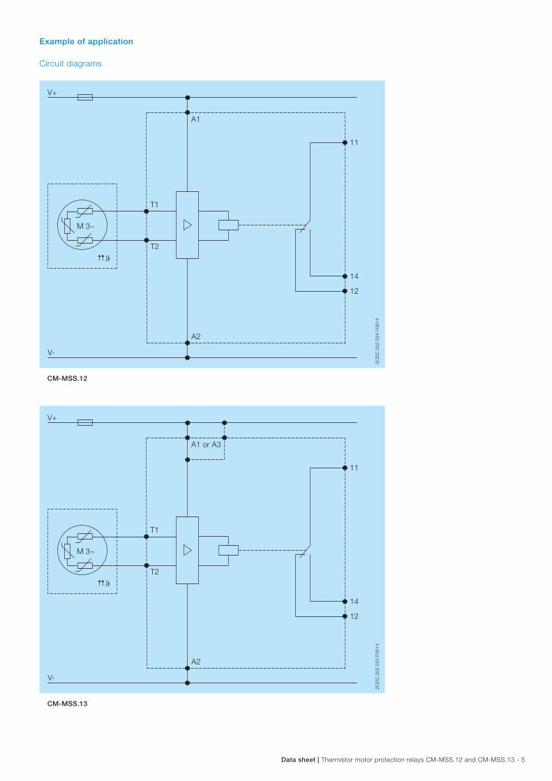
Example of application
Circuit diagrams
M 3~
V+
T2
T1
A1
V-
t
A2
14
11
12
2CD
C 2
52 0
24 F
0014
CM-MSS.12
M 3~
V+
T2
T1
A1 or A3
V-
t
A2
14
11
12
2CD
C 2
52 0
25 F
0014
CM-MSS.13
6 - Thermistor motor protection relays CM-MSS.12 and CM-MSS.13 | Data sheet
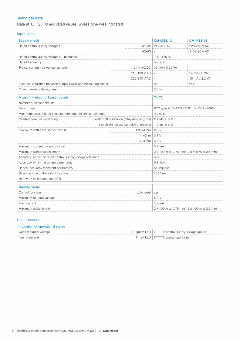
Technical data
Data at Ta = 25 °C and rated values, unless otherwise indicated
Input circuit
Supply circuit CM-MSS.12 CM-MSS.13
Rated control supply voltage Us A1-A2 24V AC/DC 220-240 V AC
A2-A3 - 110-130 V AC
Rated control supply voltage Us tolerance -15...+10 %
Rated frequency 50-60 Hz
Typical current / power consumption 24 V AC/DC 33 mA / 0.55 VA -
110-130 V AC - 24 mA / 3 VA
220-240 V AC - 10 mA / 2.2 VA
Electrical insulation between supply circuit and measuring circuit no yes
Power failure buffering time 20 ms
Measuring circuit / Sensor circuit T1-T2
Number of sensor circuits 1
Sensor type PTC type A (DIN/EN 44081, DIN/EN 44082)
Max. total resistance of sensors connected in series, cold state < 750 h
Overtemperature monitoring switch-off resistance (relay de-energizes) 2.7 kh w 5 %
switch-on resistance (relay energizes) 1.2 kh w 5 %
Maximum voltage in sensor circuit 1.33 kOhm 2.5 V
4 kOhm 3.7 V
y kOhm 5.5 V
Maximum current in sensor circuit 3.7 mA
Maximum sensor cable length 2 x 100 m at 0.75 mm², 2 x 400 m at 2.5 mm²
Accuracy within the rated control supply voltage tolerance 5 %
Accuracy within the temperature range 0.5 %/K
Repeat accuracy (constant parameters) on request
Reaction time of the safety function <100 ms
Hardware fault tolerance (HFT) -
Control circuit
Control function auto reset yes
Maximum no-load voltage 5.5 V
Max. current 1.2 mA
Maximum cable length 2 x 100 m at 0.75 mm², 2 x 400 m at 2.5 mm²
User interface
Indication of operational states
Control supply voltage U: green LED V: control supply voltage applied
Fault message F: red LED V: overtemperature
Data sheet | Thermistor motor protection relays CM-MSS.12 and CM-MSS.13 - 7
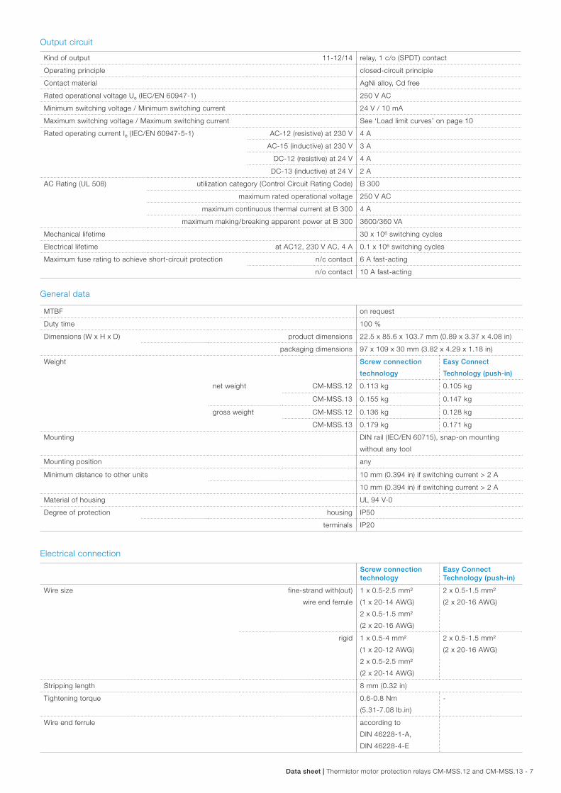
Output circuit
Kind of output 11-12/14 relay, 1 c/o (SPDT) contact
Operating principle closed-circuit principle
Contact material AgNi alloy, Cd free
Rated operational voltage Ue (IEC/EN 60947-1) 250 V AC
Minimum switching voltage / Minimum switching current 24 V / 10 mA
Maximum switching voltage / Maximum switching current See ‘Load limit curves’ on page 10
Rated operating current Ie (IEC/EN 60947-5-1) AC-12 (resistive) at 230 V 4 A
AC-15 (inductive) at 230 V 3 A
DC-12 (resistive) at 24 V 4 A
DC-13 (inductive) at 24 V 2 A
AC Rating (UL 508) utilization category (Control Circuit Rating Code) B 300
maximum rated operational voltage 250 V AC
maximum continuous thermal current at B 300 4 A
maximum making/breaking apparent power at B 300 3600/360 VA
Mechanical lifetime 30 x 106 switching cycles
Electrical lifetime at AC12, 230 V AC, 4 A 0.1 x 10⁶ switching cycles
Maximum fuse rating to achieve short-circuit protection n/c contact 6 A fast-acting
n/o contact 10 A fast-acting
General data
MTBF on request
Duty time 100 %
Dimensions (W x H x D) product dimensions 22.5 x 85.6 x 103.7 mm (0.89 x 3.37 x 4.08 in)
packaging dimensions 97 x 109 x 30 mm (3.82 x 4.29 x 1.18 in)
Weight Screw connection
technology
Easy Connect
Technology (push-in)
net weight CM-MSS.12 0.113 kg 0.105 kg
CM-MSS.13 0.155 kg 0.147 kg
gross weight CM-MSS.12 0.136 kg 0.128 kg
CM-MSS.13 0.179 kg 0.171 kg
Mounting DIN rail (IEC/EN 60715), snap-on mounting
without any tool
Mounting position any
Minimum distance to other units 10 mm (0.394 in) if switching current > 2 A
10 mm (0.394 in) if switching current > 2 A
Material of housing UL 94 V-0
Degree of protection housing IP50
terminals IP20
Electrical connection
Screw connection technology
Easy Connect Technology (push-in)
Wire size fine-strand with(out)
wire end ferrule
1 x 0.5-2.5 mm²
(1 x 20-14 AWG)
2 x 0.5-1.5 mm²
(2 x 20-16 AWG)
2 x 0.5-1.5 mm²
(2 x 20-16 AWG)
rigid 1 x 0.5-4 mm²
(1 x 20-12 AWG)
2 x 0.5-2.5 mm²
(2 x 20-14 AWG)
2 x 0.5-1.5 mm²
(2 x 20-16 AWG)
Stripping length 8 mm (0.32 in)
Tightening torque 0.6-0.8 Nm
(5.31-7.08 lb.in)
-
Wire end ferrule according to
DIN 46228-1-A,
DIN 46228-4-E
8 - Thermistor motor protection relays CM-MSS.12 and CM-MSS.13 | Data sheet
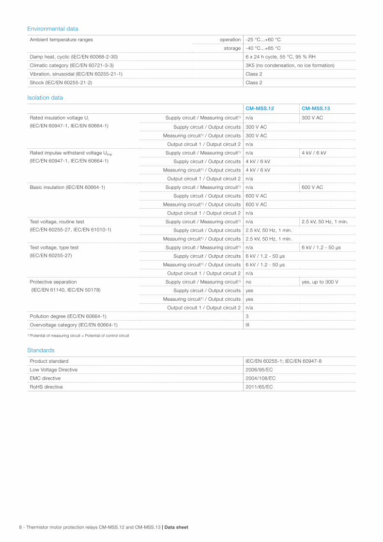
Environmental data
Ambient temperature ranges operation -25 °C...+60 °C
storage -40 °C...+85 °C
Damp heat, cyclic (IEC/EN 60068-2-30) 6 x 24 h cycle, 55 °C, 95 % RH
Climatic category (IEC/EN 60721-3-3) 3K5 (no condensation, no ice formation)
Vibration, sinusoidal (IEC/EN 60255-21-1) Class 2
Shock (IEC/EN 60255-21-2) Class 2
Isolation data
CM-MSS.12 CM-MSS.13
Rated insulation voltage Ui
(IEC/EN 60947-1, IEC/EN 60664-1)
Supply circuit / Measuring circuit1) n/a 300 V AC
Supply circuit / Output circuits 300 V AC
Measuring circuit1) / Output circuits 300 V AC
Output circuit 1 / Output circuit 2 n/a
Rated impulse withstand voltage Uimp
(IEC/EN 60947-1, IEC/EN 60664-1)
Supply circuit / Measuring circuit1) n/a 4 kV / 6 kV
Supply circuit / Output circuits 4 kV / 6 kV
Measuring circuit1) / Output circuits 4 kV / 6 kV
Output circuit 1 / Output circuit 2 n/a
Basic insulation (IEC/EN 60664-1) Supply circuit / Measuring circuit1) n/a 600 V AC
Supply circuit / Output circuits 600 V AC
Measuring circuit1) / Output circuits 600 V AC
Output circuit 1 / Output circuit 2 n/a
Test voltage, routine test
(IEC/EN 60255-27, IEC/EN 61010-1)
Supply circuit / Measuring circuit1) n/a 2.5 kV, 50 Hz, 1 min.
Supply circuit / Output circuits 2.5 kV, 50 Hz, 1 min.
Measuring circuit1) / Output circuits 2.5 kV, 50 Hz, 1 min.
Test voltage, type test
(IEC/EN 60255-27)
Supply circuit / Measuring circuit1) n/a 6 kV / 1.2 - 50 µs
Supply circuit / Output circuits 6 kV / 1.2 - 50 µs
Measuring circuit1) / Output circuits 6 kV / 1.2 - 50 µs
Output circuit 1 / Output circuit 2 n/a
Protective separation
(IEC/EN 61140, IEC/EN 50178)
Supply circuit / Measuring circuit1) no yes, up to 300 V
Supply circuit / Output circuits yes
Measuring circuit1) / Output circuits yes
Output circuit 1 / Output circuit 2 n/a
Pollution degree (IEC/EN 60664-1) 3
Overvoltage category (IEC/EN 60664-1) III
1) Potential of measuring circuit = Potential of control circuit
Standards
Product standard IEC/EN 60255-1; IEC/EN 60947-8
Low Voltage Directive 2006/95/EC
EMC directive 2004/108/EC
RoHS directive 2011/65/EC
Data sheet | Thermistor motor protection relays CM-MSS.12 and CM-MSS.13 - 9
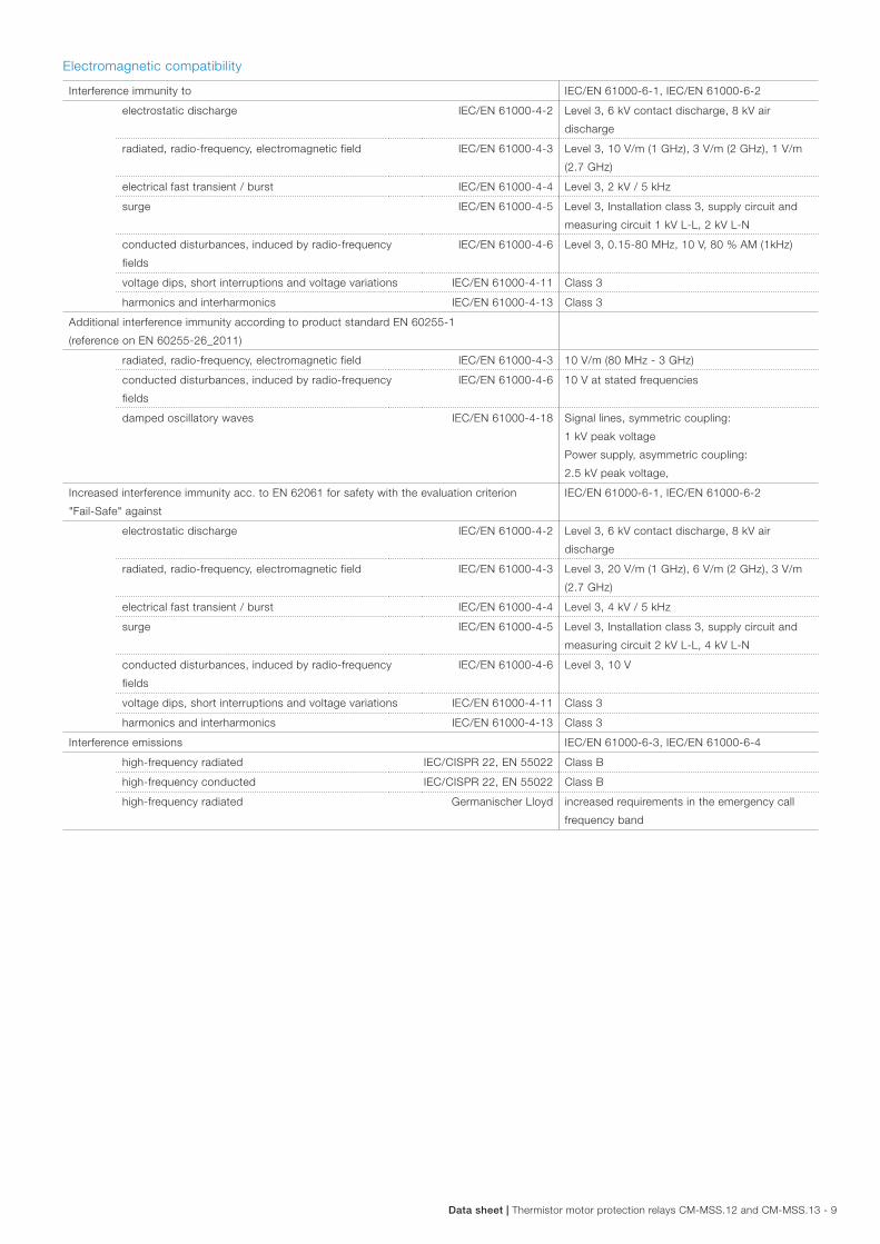
Electromagnetic compatibility
Interference immunity to IEC/EN 61000-6-1, IEC/EN 61000-6-2
electrostatic discharge IEC/EN 61000-4-2 Level 3, 6 kV contact discharge, 8 kV air
discharge
radiated, radio-frequency, electromagnetic field IEC/EN 61000-4-3 Level 3, 10 V/m (1 GHz), 3 V/m (2 GHz), 1 V/m
(2.7 GHz)
electrical fast transient / burst IEC/EN 61000-4-4 Level 3, 2 kV / 5 kHz
surge IEC/EN 61000-4-5 Level 3, Installation class 3, supply circuit and
measuring circuit 1 kV L-L, 2 kV L-N
conducted disturbances, induced by radio-frequency
fields
IEC/EN 61000-4-6 Level 3, 0.15-80 MHz, 10 V, 80 % AM (1kHz)
voltage dips, short interruptions and voltage variations IEC/EN 61000-4-11 Class 3
harmonics and interharmonics IEC/EN 61000-4-13 Class 3
Additional interference immunity according to product standard EN 60255-1
(reference on EN 60255-26_2011)
radiated, radio-frequency, electromagnetic field IEC/EN 61000-4-3 10 V/m (80 MHz - 3 GHz)
conducted disturbances, induced by radio-frequency
fields
IEC/EN 61000-4-6 10 V at stated frequencies
damped oscillatory waves IEC/EN 61000-4-18 Signal lines, symmetric coupling:
1 kV peak voltage
Power supply, asymmetric coupling:
2.5 kV peak voltage,
Increased interference immunity acc. to EN 62061 for safety with the evaluation criterion
"Fail-Safe" against
IEC/EN 61000-6-1, IEC/EN 61000-6-2
electrostatic discharge IEC/EN 61000-4-2 Level 3, 6 kV contact discharge, 8 kV air
discharge
radiated, radio-frequency, electromagnetic field IEC/EN 61000-4-3 Level 3, 20 V/m (1 GHz), 6 V/m (2 GHz), 3 V/m
(2.7 GHz)
electrical fast transient / burst IEC/EN 61000-4-4 Level 3, 4 kV / 5 kHz
surge IEC/EN 61000-4-5 Level 3, Installation class 3, supply circuit and
measuring circuit 2 kV L-L, 4 kV L-N
conducted disturbances, induced by radio-frequency
fields
IEC/EN 61000-4-6 Level 3, 10 V
voltage dips, short interruptions and voltage variations IEC/EN 61000-4-11 Class 3
harmonics and interharmonics IEC/EN 61000-4-13 Class 3
Interference emissions IEC/EN 61000-6-3, IEC/EN 61000-6-4
high-frequency radiated IEC/CISPR 22, EN 55022 Class B
high-frequency conducted IEC/CISPR 22, EN 55022 Class B
high-frequency radiated Germanischer Lloyd increased requirements in the emergency call
frequency band
10 - Thermistor motor protection relays CM-MSS.12 and CM-MSS.13 | Data sheet
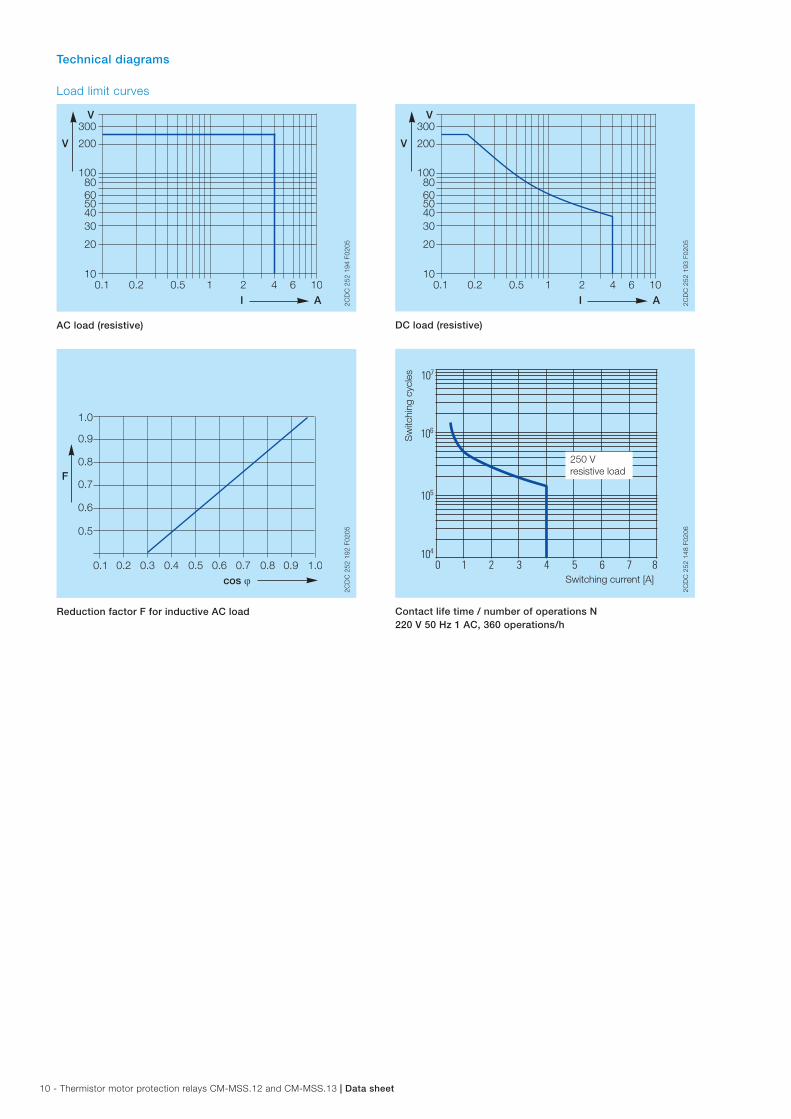
Technical diagrams
Load limit curves
300
200
1008060504030
20
101 2 4 6 10
I A
V
V
0.1 0.2 0.5
2CD
C 2
52 1
94 F
0205
AC load (resistive)
cos ϕ
F
0.5
0.1 0.2 0.3 0.4 0.5 0.6 0.7 0.8 0.9 1.0
0.6
0.7
0.8
0.9
1.0
2CD
C 2
52 1
92 F
0205
Reduction factor F for inductive AC load
300
200
1008060504030
20
101 2 4 6 10
I A
V
V
0.1 0.2 0.5
2CD
C 2
52 1
93 F
0205
DC load (resistive)
Switching current [A]
250 Vresistive load
Sw
itchi
ng c
ycle
s
2CD
C 2
52 1
48 F
0206
Contact life time / number of operations N 220 V 50 Hz 1 AC, 360 operations/h
Data sheet | Thermistor motor protection relays CM-MSS.12 and CM-MSS.13 - 11
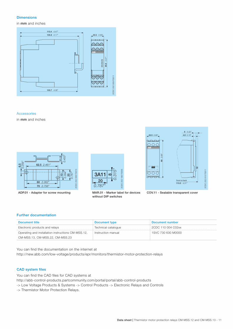
Dimensions
in mm and inches
113.4 4.47”
22.5 0.89”
85.6
3.37
”
103.7 4.08”
105.9 4.17”
2CD
C 2
52 0
09 F
0011
Accessories
in mm and inches
22.5 0.89”
68 2.68
”
110.5 4.31”
8 0.32”
4.8 0.19”
front to back
2CD
C 2
52 0
10 F
0011
6.5 62.5
60
1011
.5
20
0.25
6”
2.461”
2.362”
70 2.756”
0.39
4”
0.78
7”
0.45
3”
2CD
C 2
52 0
08 F
0010
203A11 8
0.31
5”
0.787”
2CD
C 2
52 1
86 F
0005
ADP.01 - Adapter for screw mounting MAR.01 - Marker label for devices without DIP switches
COV.11 - Sealable transparent cover
Further documentation
Document title Document type Document number
Electronic products and relays Technical catalogue 2CDC 110 004 C02xx
Operating and installation instructions CM-MSS.12,
CM-MSS.13, CM-MSS.22, CM-MSS.23
Instruction manual 1SVC 730 630 M0000
You can find the documentation on the internet at http://new.abb.com/low-voltage/products/epr/monitors/thermistor-motor-protection-relays
CAD system files
You can find the CAD files for CAD systems at http://abb-control-products.partcommunity.com/portal/portal/abb-control-products -> Low Voltage Products & Systems -> Control Products -> Electronic Relays and Controls -> Thermistor Motor Protection Relays.
ABB STOTZ-KONTAKT GmbHP. O. Box 10 16 8069006 Heidelberg, GermanyPhone: +49 (0) 6221 7 01-0Fax: +49 (0) 6221 7 01-13 25E-mail: [email protected]
You can find the address of your local sales organisation on the ABB home pagehttp://www.abb.com/contacts -> Low Voltage Products and Systems
Contact us
Note:We reserve the right to make technical changes or modify the contents of this document without prior notice. With regard to purchase orders, the agreed particulars shall prevail. ABB AG does not accept any responsibility whatsoever for potential errors or possible lack of information in this document.
We reserve all rights in this document and in the subject matter and illustrations contained therein. Any reproduction, disclosure to third parties or utilization of its contents – in whole or in parts – is forbidden without prior written consent of ABB AG.
Copyright© 2014 ABB All rights reserved
Do
cum
ent
num
ber
2C
DC
112
219
D02
01 (1
2/20
14)